a new class of patrol vessel - imdex asia 2019 · a new class of patrol vessel authors ......
TRANSCRIPT

Singapore Technologies Marine Ltd 7 Benoi Road, Singapore 629882
T: (65) 6861 2244 F: (65) 6861 3028
www.stengg.com
(Regn. No.: 196800180M)
A NEW CLASS OF PATROL VESSEL
AUTHORS
Presented by Lead Author:
Yeow Xian Ching (BEng(Hons))
Manager, Engineering Design Centre (Marine System)
Singapore Technologies Marine Ltd
A Company of ST Engineering
Co-Authored by:
Tan Ching Eng, (Dipl.-Ing, EMBA), Senior Vice President, Engineering Design Centre
Mathai Pambrakaran Pathrose (BEng(Hons)), Vice President, Engineering Design Centre
Sim Chee Chong (BEng(Hons)), Assistant Director, Engineering Design Centre (Automation Electrical
System)
SYNOPSIS
Patrol vessels play a vital role in littoral maritime security, safety of international shipping, and protection of
a state’s Exclusive Economic Zone (EEZ). This paper shares recent key developments in the design of new
generation Patrol Vessels (PVs). Missions, performance, manning, combat system outfits, and the main
characteristics of ship systems are discussed. This paper is written based on ST Marine’s proprietary design
of the Fearless Class TM Patrol Vessel.
BIOGRAPHIES
Mr. Yeow Xian Ching was appointed Manager (Engineering Design Centre, Marine System) in Feb 2016.
He is also a member in the Intellectual Property Rights Committee of ST Engineering. He was awarded
Association of Singapore Marine Industries (ASMI), Marine & Offshore Undergraduate Scholarship and
pursued a Mechanical Engineering (Marine Engineering Specialization) degree in Nanyang Technological
University. Graduated in July 2009 with a First Class Honors bachelor’s degree, he joined ST Marine. He has
been involved in several major naval and commercial new building programs. To name a few: ROPAX for
LDA, Diving Support Vessel for DOF Subsea, Landing Platform Dock for Royal Thai Navy, Patrol Vessels
for Royal Navy of Oman, Littoral Mission Vessels for Republic Of Singapore Navy and Heavy Marine Fire
Vessel for the Singapore Civil Defence Force.
Mr. Tan Ching Eng was appointed Senior Vice President (Engineering Design Centre) in Jan 2003. He is
also member in the Technologies Management Committee of ST Engineering. He was awarded Singapore
Public Service Commission (PSC) scholarship in 1981 and pursued a Naval Architecture degree in Institute
of Shipbuilding, Hamburg University. Graduated in Oct 1985 with a German Degree of “Diplom-Ingenieur”
(Master’s Degree) and a Welding Engineer Degree, he joined ST Marine (previously called Singapore
Shipbuilding and Engineering) in 1986. In 1996, he obtained a company sponsorship to pursue a part-time
Executive MBA program from State University of New York at Buffalo (SUNY) conducted at Singapore
Institute of Management (SIM), and graduated in 1999 with a MBA degree.
Mr. Mathai P Pambrakaran was appointed Vice President (Engineering Design Centre) September 2012.
He attended the Cochin University of Science and Technology in India and graduated with a Bachelor’s
Degree in Naval Architecture and Shipbuilding in 1990 and undergone a specialized training programme on
ship design at TID, The Netherlands for a period of one year, 1991-92. He started his career with Sesa Goa

Ltd and assumed various important positions with other organizations such as India’s National Ship Design
and Research Centre (NSDRC), Bureau Veritas, Dubai Dry-docks World, Lloyds Register Asia, Singapore
before joining ST Marine in 2008. He is a member of the Royal Institution of Naval Architects (RINA, UK).
Mr. Sim Chee Chong was appointed Assistant Director (Engineering Design Centre, Automation and
Electrical System) in Feb 2016. He joined ST Marine as an Engineer in 2004 after graduating from National
University of Singapore (NUS) with a Bachelor’s Degree (2nd Class Hons) in Electrical & Computing
Engineering. In his 12 years with ST Marine, Chee Chong has worked on various naval shipbuilding projects
which include the Formidable Class Frigate, Submarine Support and Rescue Vessel (SSRV), and Littoral
Mission Vessels for the Republic of Singapore Navy, Landing Platform Dock for Royal Thai Navy and
Patrol Vessels for Royal Navy of Oman.
1. INTRODUCTION
Maritime threats, which include piracy and maritime terrorism, affect the stability of national and
international economies. PVs play an integral and significant role in mitigating these threats. In addition to
the role of protecting territorial water during wartime, PV peace time operations in accomplishing Military
Operations Other Than War (MOOTW) have become increasingly important. Forming the backbone of every
maritime security fleet, PVs are used for a wide range of tasks, including naval surveillance, anti-smuggling
duties, anti-illegal immigration, anti-piracy patrols, maritime interdiction, and search and rescue operations
(SAR). In recent years, the capability of the PV has been stretched beyond her traditional roles to include
operation such as humanitarian assistance and disaster relief (HADR).
As a medium size shipyard in Southeast Asia, ST Marine has specialized in the design, construction, upgrade
and maintenance of naval and specialized commercial ships. This paper shares primarily our recent
developments of PV. These developments are based on the recent design and construction of the FearlessTM
Class PVs for the Royal Navy of Oman, and product development done in-house. Innovation and
optimization for the multi-role operations are taken into consideration in design to achieve operational
functionality and effectiveness for this class of ships.
This paper shall discuss key design process, enhanced ship platform design and combat system design based
on the Fearless 80 Mk IIITM.
2. DESIGN PROCESS
2.1 PRODUCT LIFECYCLE MANAGEMENT
Product Life Cycle Management (PLM) system has become increasingly important to shipyards and end
users in managing ship configuration from design to service and eventually disposal. The PLM system is
used as an engineering tool for design review, approval, information exchange, reporting, tracking and
resolution of technical issues for the service life of the ship.
It acts as a single shared electronic database for: the latest drawings and technical documents for design
reviews, generation of production information, maintainability assessments and logistics support analysis. It
can also integrate with 3D model software to allow design review and approval based on 3D model.
After ship delivery, end users can also access to ship system drawings and engineering data residing in PLM
database for maintenance activities, information exchange and collaboration with shipyards for system
upgrade and modification studies. Sense-making system and Service Lifecycle Management (SLM) system,
which are to be discussed in a later section in this paper, can be integrated with PLM system to achieve a full
solution of Fleet Management System (FMS).

2.2 3D MODEL BASED DESIGN
Data-centric, multidisciplinary 3D model based design tool is used for accurate and clash-free detailed design
and the creation of production information for the outfitting data of naval ships. It allows design of
equipment, piping, HVAC, miscellaneous steel structures and cable trays. Modelling is carried out in context,
using end user-defined catalogue and specification. A full range of outfitting drawings and production
information can be produced automatically from the model.
3D visualization tool for complex naval ships such as PV with features such as walk-through, animation, and
high quality photo-realistic images is used to analyze designs and communicate complex ideas. These
features allow ease of operation, maintenance and upgrade to be taken into considerations during design
phase.
With 3D model based design, large numbers of equipment, pipes, ducts, cable trays, and foundations are able
to be installed during block erection stage. Considerable cost savings can be achieved by adopting the
concept of design for Ease of Construction and Reduced Maintenance, such as the use of thicker scantlings to
reduce structure members and complexity. Ease of Installation and Maintenance is another key consideration
which can be determined with the use of 3D model during design phase. Examples include allowing for
higher deck height or space and use of pre-outfitted machinery modules.
3D model based design leads to cost savings as a result of improved engineering efficiency and effectiveness.
3. DESIGN PHILOSOPHY
3.1 ADOPTING A MIXTURE OF COMMERCIAL AND MILITARY DESIGN STANDARDS
Cost effectiveness is crucial for a PV design, build and logistics support, resulting in commercial standards
and practices being adopted to replace naval standards to an ever-increasing degree nowadays. Commercial
standards have been applied in the design of PV to a large extent in hull construction, propulsion train,
auxiliary machinery, electrical system, and navigation and communication equipment. However, mission-
critical systems and features such as weapons and sensors, and damaged stability are typically maintained to
be military or naval standard.
3.2 LIFECYCLE COST CONSIDERATIONS
Contractors are generally motivated to offer the minimum price that meets the tender requirements. However,
lifecycle cost assessment rather than capital cost alone has become criteria for evaluation. As it is not so easy
to accurately quantify lifecycle cost, and too much emphasis of this could lead to increase in the capital cost,
cost options have often allowed contractors to propose alternative solutions which may reduce the lifecycle
cost. The contractor typically uses the lowest capital cost as the base line offer. However, the contractor may
then propose options involving additional costs with justifications of lower lifecycle cost benefits.
The Commercial-Off-The-Shelf (COTS) equipment and components are likely to provide savings both in the
initial purchase and lifecycle cost. COTS designs aim to use commercial/industrial equipment and technology
to replace military system wherever feasible. Such COTS equipment should also meet certain baseline
requirements, such as reliability, system functionality, compatibility and flexibility to operate with the
existing systems. In practice, the new class of PV tends to use commercial equipment while the use of naval
standards is justified, where necessary.
3.3 REDUCED VULNERABILITY AND SUSCEPTIBILITY
In simple words, to reduce vulnerability is to reduce the probability of functions being destroyed, and to
reduce susceptibility is to reduce the probability of being detected and engaged. Independent / redundant
systems and equipment that are arranged further apart are becoming evermore considered in the new PV
design.

The key systems considered are:
Independent propulsion trains separated by fire rated bulkhead and watertight bulkhead
Independent electrical power supply with associated Main Switchboard (MSB) such that vital
equipment could be fed from either MSB space
Redundant HVAC system especially one that has Chemical, Biological, Radioactive and
Nuclear (CBRN) protection
Redundant circuit for signal and control system i.e. Integrated Platform Management System
(IPMS)
Redundant piping network for critical propulsion systems
4. DESIGN OF THE SHIP PLATFORM
Among the many parameters and requirements, the followings are key considerations for designing the new
class of PV.
4.1 MULTI-MISSION CAPABLE
The offshore-capable PV is significantly more cost effective because she is capable of performing many
different roles that previously could only be carried out with other larger naval and coast guard assets. These
different roles are:
Patrol and surveillance of territorial waters as well as Exclusive Economic Zone (EEZ)
Search and rescue operations (SAR)
Maritime pollution control
Counter terrorism
Anti-piracy
Customs enforcement including anti-smuggling
Launch and extraction of special forces
Humanitarian assistance and disaster relief (HADR)
With standard container-sized mission module developed and made available off-the-shelf (and many
potential mission modules are being developed now), the PV platform design is trending towards modular
payload capability. The developed solutions aim to be flexible and configurable so that the PV is capable to
receive various standard mission modules that are connected with the multi-function console system to
perform a wide range of tasks by the embarked specialists.
The platform is therefore modified and adapted with delegated mission bay or mission deck space, interface
facilities such as power and signal cables and multi-function consoles, and accommodation facilities to
receive the embarked specialists. The PV is manned by core crew complements that are capable of multi-
tasking to perform the baseline operations. Multi-mission capable PV requirement is evident in a number of
recent projects. Examples are as follow:
Republic of Singapore Navy’s Littoral Mission Vessel,
Royal Australian Navy’s Project SEA 1180,
Brazilian Navy’s OPV PROSUPER program,
Venezuela Navy’s OPV POVZEE program.
4.2 SUPERIOR SHIP PERFORMANCE
PVs are often required to operate for extended periods either independently or as part of a deployed task
force, to operate in national or multi-national forces in littoral waters.
Their primary mission is to patrol and protect inshore and offshore facilities. To do so, they are designed to
operate away from base and stay longer at seas. Thus, longer range, greater endurance and replenishment at
sea are required. Activities in open seas will be often limited to transit. The PV performing this role need to
be capable of protecting herself against surface ships and gain superiority over smaller units, which may
come from sudden attacks from the shore. Their secondary missions encompass embargo control, UN
mission, humanitarian assistance and disaster relief, custom and coast guard activities.
The new class of PV may require conducting offensive strike missions. In this case, the goal is to be able to
project fire power in a short time. The PVs are part of a deterrent force in national and multi-national mission.
These PVs are designed with higher speed, greater endurance and fitted with combat system for ASuW
and/or ASW and capable of self-defense against air, surface and underwater threats.
4.2.1 Speed
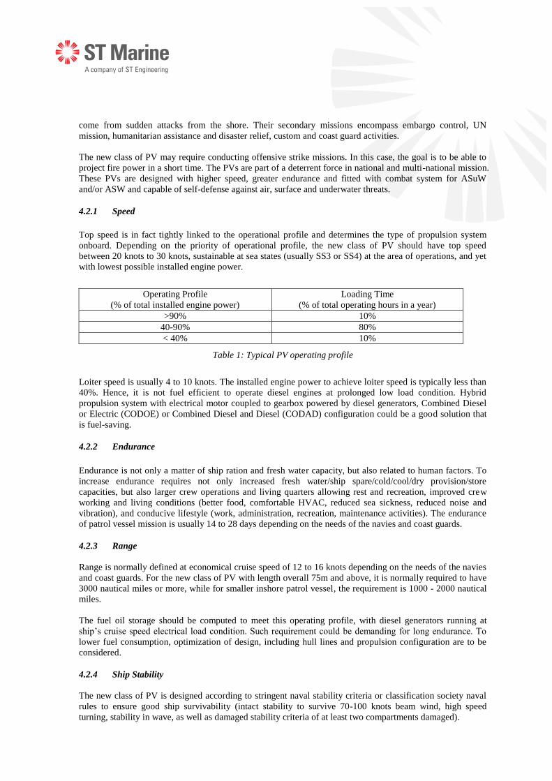
Top speed is in fact tightly linked to the operational profile and determines the type of propulsion system
onboard. Depending on the priority of operational profile, the new class of PV should have top speed
between 20 knots to 30 knots, sustainable at sea states (usually SS3 or SS4) at the area of operations, and yet
with lowest possible installed engine power.
Operating Profile
(% of total installed engine power)
Loading Time
(% of total operating hours in a year)
>90% 10%
40-90% 80%
< 40% 10%
Table 1: Typical PV operating profile
Loiter speed is usually 4 to 10 knots. The installed engine power to achieve loiter speed is typically less than
40%. Hence, it is not fuel efficient to operate diesel engines at prolonged low load condition. Hybrid
propulsion system with electrical motor coupled to gearbox powered by diesel generators, Combined Diesel
or Electric (CODOE) or Combined Diesel and Diesel (CODAD) configuration could be a good solution that
is fuel-saving.
4.2.2 Endurance
Endurance is not only a matter of ship ration and fresh water capacity, but also related to human factors. To
increase endurance requires not only increased fresh water/ship spare/cold/cool/dry provision/store
capacities, but also larger crew operations and living quarters allowing rest and recreation, improved crew
working and living conditions (better food, comfortable HVAC, reduced sea sickness, reduced noise and
vibration), and conducive lifestyle (work, administration, recreation, maintenance activities). The endurance
of patrol vessel mission is usually 14 to 28 days depending on the needs of the navies and coast guards.
4.2.3 Range
Range is normally defined at economical cruise speed of 12 to 16 knots depending on the needs of the navies
and coast guards. For the new class of PV with length overall 75m and above, it is normally required to have
3000 nautical miles or more, while for smaller inshore patrol vessel, the requirement is 1000 - 2000 nautical
miles.
The fuel oil storage should be computed to meet this operating profile, with diesel generators running at
ship’s cruise speed electrical load condition. Such requirement could be demanding for long endurance. To
lower fuel consumption, optimization of design, including hull lines and propulsion configuration are to be
considered.
4.2.4 Ship Stability
The new class of PV is designed according to stringent naval stability criteria or classification society naval
rules to ensure good ship survivability (intact stability to survive 70-100 knots beam wind, high speed
turning, stability in wave, as well as damaged stability criteria of at least two compartments damaged).

4.2.5 Seakeeping Performance
At operational sea state, the criteria for patrol vessel are as follow:
Fulfill ship seaworthiness criteria (preferably have superior sea-keeping performance characteristic)
Fulfill crew comfort criteria for personnel onboard
Capability to meet the combat system criteria
Capable to take-off and land helicopter (if fitted with helideck)
Capable to launch and recover sea boats
Capable to sustain operational speed
At survival sea state, the key concern is the ship structural strength, particularly the longitudinal wave
bending stress, and localized structure (bow flare and bottom structure) subjected to slamming loads. Besides
careful hull lines design to reduce such load, global and localized hull structure strengthening is necessary for
the PV. In considering extreme weather conditions and heavy seas, the ship’s commanding officer should be
warned in the ship’s operation handbook to reduce speed and avoid heading towards any safety limitation.
Roll damping and stabilizing are essential for PV. Bilge keel and / or active fin stabilizer are necessary to
ensure good seakeeping at beam sea condition. Other sea keeping characteristics, including pitching, vertical
accelerations, deck wetness, bow height, etc. should also be carefully examined either through predictive
calculations or model testing to ensure crew’s operation effectiveness of combat system and ship system.
4.3 EFFICIENT HULL FORM
The hull form emphasizes on hydrodynamic performance to satisfy ship performance and operational
requirements. The hull geometry is expected to derive from a proven yet modern hull form, where the
hydrodynamic performance is predictable. In some cases, new hull forms are created through direct design or
with significant modification from an existing hull form, but model tested to validate the performance.
Through the use of Computational Fluid Dynamic (CFD) methodology, the designer could optimize the hull
form and appendages geometry. CFD could predict the characteristics of the flow around the hull. In
comparison to model tests, CFD is capable of performing full scale computations, and is useful in verifying
changes in wave resistance in different hull alterations in a relatively short time and with lower costs, and to
arrive at a confident level of optimization prior to model testing.
Nevertheless, model testing in the towing tank facility should be performed to validate the resistance, shaft
power, measure the wake at propeller, and may conduct paint tests for hull appendages (rudder, shaft strut,
bilge keel, bow thruster, etc.) arrangement. In some cases, it is also used to optimize certain parts of the hull
form design, such as the stern wedge configuration. Other kinds of model testing usually carried out are open
water efficiency tests and cavitation tests for design propeller, sea-keeping performance and maneuverability
(turning circle, zig-zag turning).
The overall technical aim is to develop a hull form capable of highest top speed, fuel economical at cruising
speed, with good sea-keeping and maneuvering performance.
1. Developed highly efficient hull form with good hydrodynamic performance and less fuel
consumption by CFD software
a. Optimized hull form and ship appendages (shaft strut, scallop of bow thrusters, bilge keel)
by using CFD simulation.
b. Propeller optimization, including incorporating a tunnel in the hull to enlarge propeller
diameter for better performance.

Figure 1: Fearless 80 Mk IIITM hull form
2. Optimized hull form and appendages by extensive model tests
a. Rudder angle optimization
b. Trim wedge optimization incorporated into hull form
c. Propeller rotation direction optimization
Figure 2: Appendages optimization test
Figure 3: Key improvements of the hull form
3. The hull form developed is superior in terms of speed, maneuvering and sea-keeping capabilities as
compared to hull designs of similar fast crafts. In order to validate the hull form design, extensive
model tests have been conducted.
a. Resistance & Propulsion Test
b. Manoeuvring Test
c. Sea-keeping Test
1. Hull form optimised using CFD
3. Stern wedge reduces ship resistance
4. Shaft strut and rudder orientation optimised
2. Bulbous bow reduces ship
resistance

(a) Propulsion test (b) Manoeuvring test (c) Sea-keeping test
Figure 4: Propulsion, maneuvering and sea-keeping model test
4. Optimal propeller and rudder design has been verified by propeller cavitation test in order to avoid
cavitation behavior and to obtain the best ship speed performance. Underwater noise signature has
been reduced as a result of reduced cavitation and pressure pulses.
Figure 5: Propeller design and cavitation test
4.4 HYBRID PROPULSION SYSTEM
Electric propulsion has been considered for the PV. One key advantage of a ship with electric propulsion is
the flexibility of use in the distribution of electrical power to the three main consumers: propulsion, ship
service system and combat system. Electric propulsion also enables better equipment layout (for example, by
locating the diesel generators elsewhere than the ship’s bottom deck) and by judiciously distributing the
diesel generators.
The PV is equipped with a hybrid propulsion system whereby the propulsion train is driven by one main
engine and one electric motor coupled to a gear unit known as Combined Diesel Or Electric (CODOE) in
short. The shafting system is completed with a controllable pitch propeller. The main engine is used for
cruising at 16 knots and in high speed operation of more than 25 knots. The electric motor is used during
loitering condition at low speed operation of 10 knots and below.
The Key Challenge was to perform major equipment selection and to ensure that the integration achieve
specified performance. The main engine, electric motor, gear unit, shaft line and associated auxiliary such as
cooling pumps, controllable pitch propeller and flexible couplings have to be integrated both mechanically
and electrically in order to achieve functional requirement. Software integration is another challenge whereby
the propulsion remote control system has to be integrated in order to provide the necessary sequence of
various modes of operations.
The approach to overcome these challenges was to perform systematic design and integration reviews and
workshops with the participation of experts, equipment manufacturers and designers.

The key benefit of having hybrid propulsion is to fulfill the operational profile of the vessel whereby the
propulsion and vessel service power demand has large variations. By using propulsion e-motor at slow speed,
it results into fuel efficiency and low noise operation at low speed.
Figure 6: Typical load operation profile of Hybrid Propulsion
4.5 TOPSIDE ARRANGEMENT
In general, the topside arrangement takes into considerations of the mast, funnel (if fitted), helideck (if fitted),
weapon suite, and sensors. Maximum weapon and sensor coverage, and distribution of combat system as far
apart as possible for enhanced survivability would allow the ship to retain degraded capability should she be
hit.
4.5.1 Modular Mast
The Modular Mast will house communication antennas, navigation, surveillance sensors and electronic
cabinets within the mast structure. The Modular Mast size and height is also shaped and streamlined for
optimal air flow.
The main challenge of Modular Mast is to achieve electromagnetic compatibility (EMC) with all the
transmitters and receivers installed close to each other due to the limited space on the mast and these systems
work across a wide frequency range. Detailed EMC studies and simulations were carried out with system
suppliers, with the outcome of an optimize sensors and antennas arrangement and structural design of the
Modular Mast.
Figure 7: 3D model of in-house designed Modular Mast

4.5.2 Optimal Superstructure Shaping
4.5.2.1 Wind Tunnel Test
Smoke recirculation to the working areas and the air intakes can be a challenge for ships, especially for Navy
vessels, where the requirements with regard to smoke on the decks will be higher than for other ships. Smoke
recirculation to the working areas must be minimized. Wind tunnel test was conducted to validate the
dispersion of the exhaust gases from the diesel engines’ exhaust pipes.
The study indicated that diesel engines’ exhausts gasses are re-circulating at helicopter deck at most of the
tested angles in all flow conditions.
The superstructure/mast is located in front of the (much smaller) funnel; this arrangement produces increased
turbulent wake at the location of the funnel. As long as the exhaust gasses are trapped inside the turbulent
wake of the vessel, they will not disperse away from the vessel.
Figure 8: The 1:60 scale model of Fearless 75TM Patrol Vessel in the wind tunnel
4.5.2.2 Funnel, Exhaust Pipe and Mast Design
As a result of the wind tunnel test, the exhaust pipe & funnel design was reviewed and improved by taking
into consideration the exhaust gas recirculation and impingement on the helicopter deck. This is critical to
ensure safe landing of helicopter and crew operation safety. Several designs of the exhaust pipe top piece
were simulated and tested again through CFD and wind tunnel test. After several extensive design iterations
and tests, the final design with an extension of the exhaust pipe outside the funnel top with a 45 degree bend
was conceived as the best design.
To further enhance the funnel design, an “extended lip” was added to the funnel top to prevent exhaust gas
flowing downward to the helicopter deck. The funnel bulkhead was added with more louver openings to
allow better air flow. Other improvements include change of geometry of the funnel to allow slimmer and
higher funnel. In addition to the funnel and exhaust pipe design, the mast shape was improved and slimmed
down to reduce the blockage of wind and turbulent wake.

Figure 9: CFD Simulations and Wind Tunnel Test
In order to reduce the infrared signature of the exhaust gasses, the extension pipe was innovatively designed
to have a double wall which captures the surrounding air as a layer of thermal insulation. The engine room
exhaust ventilation system is integrated with the funnel to allow exhaust air from engine room to cool down
the engines’ exhaust fume temperature.
4.6 INTELLIGENT POWER MANAGEMENT SYSTEM
A minimum of two independent, 100% redundant electrical switchboard shall be considered. There shall be
one additional diesel generator on standby at the worst possible operation scenario. Vital equipment shall
have dual power supply from either switchboard.
In addition, an Intelligent Power Management System (i-PMS) can be incorporated into the new class of PV
design, to perform diesel generator scheduling - a process to load the diesel generators differently rather than
equally when running parallel to optimize fuel consumption. The i-PMS system is particularly useful when
the PV is on electric motor propulsion mode (refer to 4.4 Hybrid Propulsion System) in which a third
generator is to cut in to support the existing two generators in electrical load needed for hotel and propulsion
services concurrently. Potential DC grid system with variable speed diesel generators can add on to the fuel
savings. However, implementation of DC grid system makes more sense only on vessel that operates fully on
diesel electric propulsion system.
4.7 DATA CENTRIC
Data analytics on marine applications has gained a lot of interest over the last few years. As a result of
technological advancement and cost reduction in both data storage and computing power, there are huge
amount of system data available where analytics may be applied to gain new system insights. Advance
analytics may even be applied to allow for predictive and prognostic analysis, pathing the way for a
predictive maintenance and condition based maintenance instead of the traditional preventive and corrective
maintenance regime.
New PVs should be designed and built for data. During the design process, areas where analytics are to be
applied should be established so that the required sensors are identified upfront, built into the platform
systems and catered for in the ship design.
The next step is data collection or data acquisition. PVs are typically equipped with Integrated Platform
Management System (IPMS) or Ship Management System (SMS) which is capable of collecting analogue
and digital data from all shipboard systems in a single platform for centralized monitoring and control.
The IPMS or SMS can be enhanced with a Sense-making module that performs real time analytics on
shipboard systems’ data to provide health monitoring and predictive or pre-emptive warning of imminent

equipment/system failure, which can be further supplemented with advisory actions from a Decision Support
function.
The Sense-making module can be extended to a shore-based center to form a Fleet Management System,
where data collected onboard ships are sent back to shore via the ship’s SATCOM facilities for fleet-wide
analytics. Advisory actions or deployment instructions can then be sent from shore back to the ships out at
sea. It should be noted that the choice of SATCOM and cyber security, which are not discussed in this paper,
are also important points that need to be considered in the ship design, in order to facilitate the Fleet
Management concept described above.
4.8 LEAN MANNING
Crew numbers have reduced significantly with each generation of warship, but still remain a significant space
driver in the ship design. While the watch and station bill is generally determined by manning scenarios
based on operational experience of the navy, with the recent advancement of technology in ship automation
and remote control weapon system, manning level could be reduced significantly.
In determining the complement level, platform and combat systems level of automation, and the cost
associated with it are generally the key considerations. The following systems’ design could drive down the
manning requirements:
Integrated Platform Management System (IPMS)
Integrated Bridge System
Unmanned machinery space
CCTV surveillance system
Damaged control system
It is also important to train crew to be proficient in operating highly automated systems in order to achieve
safe operation while low manning is being considered.
4.9 ENVIRONMENTAL FRIENDLY DESIGN
Recent international legislations by the International Maritime Organization (IMO) require more stringent
control of handling ship wastes for pollution prevention. Governments are increasingly obliged by the
regulations, whether in whole or part, in order to set good example.
Recent SOx and NOx emissions limits have seen not only the commercial sector complying with the new
regulations but the navies as well. Ship building specification by the navies has required engine with
minimum TIER II compliance and the use of clean Marine Diesel Oil (MDO) or Marine Gas Oil (MGO).
Table 2: MARPOL Annex VI, SOx emission limits

Figure 10: MARPOL Annex VI, NOx Tier I-II-III requirements
Another recent pollution prevention regulation is the enforcement of IMO Ballast Water Management
Convention starting 8th September 2017. Ballast water treatment system has been mandated or made
provision by most navies in ship building specification. Ballast water treatment system includes the use of
filter, hydro-cyclone and ultra violet light to abate marine microorganisms from entering the ship’s ballast
tanks and subsequently being discharge to another location and cause harmful effects to the local marine eco
system.
5. DESIGN OF THE SHIP COMBAT SYSTEM
5.1 COMBAT SYSTEM
PVs are mainly equipped with medium-caliber guns and machine guns. However PVs have the potential to increase the military payload and self-defense (CIWS or AAM) system with the increase of size. Heavily armed patrol vessels would look more attractive, but should avoid functionally overkill. PVs are typically equipped with remote control main gun of medium caliber 57 to 76mm and 12.7 to 30mm
secondary guns, as appropriate to the size of ship. These guns provide the PVs with 360 degree defensive and
offensive coverage. Wing guns are normally 0.5 inch caliber machine guns.
Surface-to-Surface Missile (SSM) launchers and Anti-Air Missiles (AAM) are integrated to the
superstructure and deck spaces. Soft-kill chaff and decoy systems are located on the superstructure deck or
forward of superstructure.
The procurement of the combat system could either be part of turnkey contract or be a separate program. The
procurement strategy for the vessel must address the precise way in which the overall integration of combat
system and platform is to be achieved and, in particular, the roles and responsibility for the various parties in
the program. This process will inevitably create an area of uncertainty and risk for possible schedule and cost
overrun. There is also risk of technical impact (weight, electrical load, heat load, etc.). Allocation of
responsibility within a commercial contract framework is therefore important to manage the program and
mitigate the risks involved.
5.2 COMMAND, CONTROL COMMUNICATION, COMPUTER AND INTELLIGENCE (C4I)
SYSTEM
The combined Joint Task Force is widely used as a model for peacekeeping and other comparable operations.
In the maritime field, to assemble an international task force for an agreed mission, and to deploy, support,
and conduct possible opposed operations with full coordination of all assets, sensors and weapons is a
complex operation. Interoperability of Command, Control, Communications and the exchange of Intelligence
is key to successful conduct of Alliance/Coalition operations which have accounted for the majority, if not all,
military operations. New class of PV configuration shall have a minimum C2 system with C4I system
capable design.
5.3 HELICOPTER AND UNMANNED ARIEL VEHICLE (UAV) CAPABILITY
Operating a helicopter from a PV has always been a tough design requirement. Military specifications related
to helicopter operations are demanding including sea-keeping characteristic of ship, landing area, clearance
distances, air flow around landing spot, landing aid, control and communication, fire safety, structure load
during normal landing and in the event of crash landing, storage and maintenance capability (for an
embarked helicopter), onboard training, operation procedure, etc. In the frame work of an UN mission task
force, the PV should be able to receive a helicopter of another navy, or be able to receive an army helicopter
when operate in coastal waters. It is therefore necessary to certify the landing deck for a range of helicopters
during design and commissioning.
However, a PV’s capability is significantly increased if she is able to accommodate a combat helicopter or a
UAV with significant operational roles. UAV capable PV has become almost a new and standard
requirement for the new class of PV. In view of this, it is important that the design considers incorporating
the capability to land and take-off of a medium size helicopter or a UAV, and to accommodate a fixed hangar
for a larger patrol vessel.
6. CONCLUSION
The recent development trend in PVs has been towards a new class of multi-mission vessel, designed and
built with efficient hull form, equipped with hybrid propulsion, intelligent power management system, with
higher level of automation coupled with Sense-making to aid the end users in their operations. The
superstructure design is optimized to reduce radar cross section signature, infrared signature and exhaust gas
recirculation. The mast design has to consider all the various antennas, sensors and radars EMI/EMC
requirements. With the above mentioned design considerations and features, a new class of PV will definitely
serve its multi role purpose and meet navies ever increasing expectation. These objectives can be achieved
with everyone in the program team, including operator, contractor and suppliers working closely to integrate
their efforts towards the same common objective.
7. ACKNOWLEDGEMENTS
The lead author and co-authors would like to express our sincere gratitude towards the Engineering Design
Centre teams who have contributed to the success of the Fearless Class™ Patrol Vessel program. In addition
to the engineering team, we would like to thank our colleagues from operations, quality assurance,
purchasing, commissioning, and other supporting functions for their effort in supporting and completing the
build program of Al-Ofouq Class Patrol Vessel. The Al-Ofouq Class Patrol Vessel program has contributed
significantly to the Fearless 80 Mk III™ design. Lastly, the authors would like to thank ST Marine top
management for their relentless support and guidance.
8. FIGURES
Figure 1: Fearless 80 Mk IIITM hull form .......................................................................................................... 7
Figure 2: Appendages optimization test ............................................................................................................ 7
Figure 3: Key improvements of the hull form .................................................................................................... 7
Figure 4: Propulsion, maneuvering and sea-keeping model test ...................................................................... 8
Figure 5: Propeller design and cavitation test .................................................................................................. 8
Figure 6: Typical load operation profile of Hybrid Propulsion ........................................................................ 9
Figure 7: 3D model of in-house designed Modular Mast.................................................................................. 9
Figure 8: The 1:60 scale model of Fearless 75TM Patrol Vessel in the wind tunnel ........................................ 10

Figure 9: CFD Simulations and Wind Tunnel Test ......................................................................................... 11
Figure 10: MARPOL Annex VI, NOx Tier I-II-III requirements ..................................................................... 13
9. TABLES
Table 1: Typical PV operating profile ............................................................................................................... 5
Table 2: MARPOL Annex VI, SOx emission limits .......................................................................................... 12