a history of - apollo valves history of quality, service and ... backflow prevention devices, water...
TRANSCRIPT

A history ofQuality, Service and Innovation
Now in its ninth decade, Conbraco Industries, Inc. is a leading manufacturer of flow control products for U.S. and international markets. The company’s headquarters is based in Matthews, North Carolina with manufacturing plants and foundries located in Pageland and Conway, South Carolina.
Conbraco has a history of new product development and innovation that dates back to the company’s inception in 1928. Today, the Conbraco line of products is marketed under the “Apollo Valves” brand and includes: ball valves, butterfly valves, backflow prevention devices, water pressure reducing valves, mixing valves, safety relief valves, water gauges, strainers, actuation and APOLLOXPRESS® products.
Conbraco’s vertically integrated manufacturing ensures a consistency of production, testing, quality and availability. You can be assured that Conbraco flow control products will deliver long term reliability. All manufacturing facilities are ISO 9001:2008 certified.
The Conbraco line continues to expand with new products, designs and advanced materials to better serve the needs of our customers. Markets served include: chemical processing, pulp and paper, petroleum, residential and commercial plumbing and heating, OEM, irrigation, water works, and fire protection.
A LONG, SUCCESSFUL HISTORY IN SAFETY AND RELIEF VALVES
Conbraco has been designing and producing ASME safety and relief valves for eight decades. Its portfolio includes more than 30 models of valves carrying the ASME Section I, Section IV and Section VIII designations. These products are specified around the globe for use in boilers, sterilizers, air compressors and a broad spectrum of commercial, industrial and OEM applications.
The company offers safety and relief valves with brass, bronze, cast iron, carbon steel and stainless steel body construction. Available in inlet sizes from 1⁄4” through 6”, Conbraco valves are certified for steam, air/gas and liquid service, with set pressures up to 1,200 psi.
As part of its total quality program, Conbraco provides 100 percent factory testing of safety and relief valves prior to shipment. It maintains a network of regional ASME certified setting stations that offer prompt deliveries as well as factory authorized sales, service and repair.
Every Conbraco safety and relief valve represents our proud tradition of providing customers with real value and satisfying their needs with unmatched efficiency, consistency and speed.
This catalog provides you with a full overview of the Conbraco safety and safety relief valve product line plus information on proper valve selection and application. If you have any questions, please don’t hesitate to contact your nearest Conbraco factory representative, authorized setting station or Conbraco customer service.
SAFETY & RELIEF VALVES
Customer Service (704) 841-6000For additional information, submittal sheets and manuals, visit www.apollovalves.com
3
PRODUCTS PAGE NO.
Valve Selection Guide ........................................................................................................................................................................................ 4
10 Series .............................................................................................................................................................................................................. 5-6
10-322 / 10-512 Series .................................................................................................................................................................................. 7-8
10-600 Series ....................................................................................................................................................................................................9-11
12-200 Series .................................................................................................................................................................................................12, 15
13 Series ..........................................................................................................................................................................................................13, 15
14-200 Series .................................................................................................................................................................................................14-15
14-400, 14-500, 14-600 ..............................................................................................................................................................................16-19
15 Series ......................................................................................................................................................................................................... 20-21
16 Series ......................................................................................................................................................................................................... 22-23
17-400 Series ...................................................................................................................................................................................................... 24
18C-400 & 18C-402X Series........................................................................................................................................................................... 25
18C-500 Series ................................................................................................................................................................................................... 26
19 Series ......................................................................................................................................................................................................... 27-31
29 Series ......................................................................................................................................................................................................... 32-36
119 Series ...................................................................................................................................................................................................... 37-41
Drip Pan Elbows ................................................................................................................................................................................................ 42
500 Series ...................................................................................................................................................................................................... 43-48
Equivalents and Conversion Factors ......................................................................................................................................................... 49
Correction Factors ............................................................................................................................................................................................ 50
Warranty Information ...................................................................................................................................................................................... 51
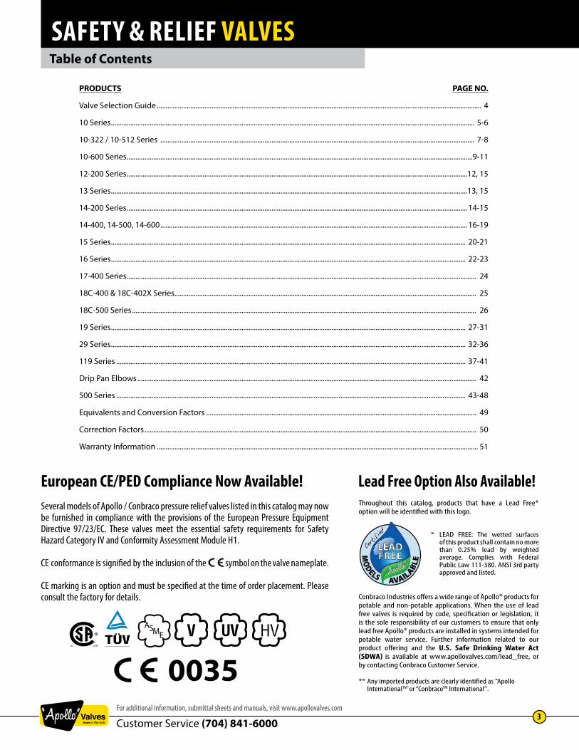
European CE/PED Compliance Now Available!Several models of Apollo / Conbraco pressure relief valves listed in this catalog may now be furnished in compliance with the provisions of the European Pressure Equipment Directive 97/23/EC. These valves meet the essential safety requirements for Safety Hazard Category IV and Conformity Assessment Module H1.
CE conformance is signified by the inclusion of the symbol on the valve nameplate.
CE marking is an option and must be specified at the time of order placement. Please consult the factory for details.
0035ASME
Table of Contents
Lead Free Option Also Available!Throughout this catalog, products that have a Lead Free* option will be identified with this logo.
Conbraco Industries offers a wide range of Apollo® products for potable and non-potable applications. When the use of lead free valves is required by code, specification or legislation, it is the sole responsibility of our customers to ensure that only lead free Apollo® products are installed in systems intended for potable water service. Further information related to our product offering and the U.S. Safe Drinking Water Act (SDWA) is available at www.apollovalves.com/lead_free, or by contacting Conbraco Customer Service.
** Any imported products are clearly identified as “Apollo InternationalTM” or “ConbracoTM International” .
* LEAD FREE: The wetted surfaces of this product shall contain no more than 0.25% lead by weighted average. Complies with Federal Public Law 111-380. ANSI 3rd party approved and listed.

SAFETY & RELIEF VALVES
Customer Service (704) 841-60004
www.apollovalves.com
Pressure Relief Valve Selection ChartModel Material
Body / TrimInlet Sizes
Min / Max, in.Inlet Sizes
Min / Max, mm.Connections CE/PED
AvailableSet Pressures
Min / Max, PSIGSet Pressures
Min / Max, bargTemperature
Max, ˚FTemperature
Max, ˚CNPT FlangedASME Section I - Steam Power Boilers
19M Bronze / Brass 1/2 - 2 1/2 DN 15 - 65 X X 15 - 250 1.0 - 17.2 406˚F 207.7˚C19K Bronze / Brass 1/2 - 2 1/2 DN 15 - 65 X X 15 - 250 1.0 - 17.2 406˚F 207.7˚C19L Bronze / Stainless 1/2 - 2 1/2 DN 15 - 65 X X 15 - 250 1.0 - 17.2 406˚F 207.7˚C19S Bronze / Stainless 1/2 - 2 1/2 DN 15 - 65 X X 15 - 300 1.0 - 20.7 422˚F 216.7˚C29 Bronze / Brass 3/8 - 1 1/4 DN 10 - 32 X X 30 - 200 2.0 - 13.8 406˚F 207.7˚C
119 Cast Iron / Stainless 1-1/2 - 6 DN 40 - 150 X X X 15 - 250 1.0 - 17.2 450˚F 232.2˚CASME Section IV - Low Pressure Steam Heating Boilers
12 Bronze / Brass 2 - 3 DN 50 - 80 X 5 - 15 0.34 - 1.0 250˚F 121.1˚C13-101 Bronze / Brass 3/4 DN 20 X 5 - 15 0.34 - 1.0 250˚F 121.1˚C13-202 Bronze / Brass 1 DN 25 X 5 - 15 0.34 - 1.0 250˚F 121.1˚C13-211 Bronze / Brass 3/4 DN 20 X 5 - 15 0.34 - 1.0 250˚F 121.1˚C13-213 Bronze / Brass 1-1/4 DN 32 X 5 - 15 0.34 - 1.0 250˚F 121.1˚C13-214 Bronze / Brass 1-1/2 DN 40 X 5 - 15 0.34 - 1.0 250˚F 121.1˚C13-510 Bronze / Brass 3/4 DN 20 X 5 - 15 0.34 - 1.0 250˚F 121.1˚C14-200 Bronze / Brass 2 - 3 DN 50 - 80 X 5 - 15 0.34 - 1.0 250˚F 121.1˚C
ASME Section IV - Hot Water Heating & Supply Boilers10-100 Bronze / Brass 3/4 DN 20 X 20 - 65 1.4 - 4.5 250˚F 121.1˚C10-300 Bronze / Brass 3/4 DN 20 X 20 - 65 1.4 - 4.5 250˚F 121.1˚C10-400 Bronze / Brass 3/4 DN 20 X 30 2.0 250˚F 121.1˚C10-410 Bronze / Brass 3/4 DN 20 X 20 - 80 1.4 - 5.5 250˚F 121.1˚C
10-600, 10-610 Bronze / Brass 3/4 - 2 DN 20 - 50 X X 15 - 160 1.0 - 11.0 250˚F 121.1˚C10-624, 10-634 Bronze / Brass 3/4 DN 20 X 30 - 150 2.0 - 10.3 250˚F 121.1˚C
17-401 Bronze / Brass 1/2 DN 15 X 75 - 160 5.2 - 11.0 250˚F 121.1˚C17-402 Bronze / Brass 3/4 DN 20 X 75 - 150 5.2 - 10.3 250˚F 121.1˚C
18C-400 Bronze / Brass 1/2 - 3/4 DN 15 - 20 X 125 - 175 8.61 - 12.1 210˚F 98.9˚C18C-500 Bronze / Stainless 3/4 - 2 DN 20 - 50 X 75 - 150 5.2 - 10.3 210˚F 98.9˚C
ASME Section VIII Air / Gases15 Brass 1/4 - 1 DN 8 - 25 X X 15 - 250 1.0 - 17.2 325˚F 162.8˚C
19M Bronze / Brass 1/2 - 2-1/2 DN 15 - 65 X X 8 - 300 0.55 - 20.7 406˚F 207.7˚C19K Bronze / Brass 1/2 - 2-1/2 DN 15 - 65 X X 15 - 300 1.0 - 20.7 406˚F 207.7˚C19L Bronze / Stainless 1/2 - 2-1/2 DN 15 - 65 X X 15 - 300 1.0 - 20.7 406˚F 207.7˚C19S Bronze / Stainless 1/2 - 2-1/2 DN 15 - 65 X X 8 - 300 0.55 - 20.7 422˚F 216.7˚C29 Bronze / Brass 3/8 - 1-1/4 DN 10 - 32 X X 30 - 200 2.0 - 13.8 406˚F 207.7˚C
119 Cast Iron / Stainless 1-1/2 - 6 DN 40 - 150 X X X 8 - 250 0.55 - 17.2 450˚F 232.2˚C510 Bronze / Brass 1/2 - 2 DN 15 - 50 X X 8 - 300 0.55 - 20.7 406˚F 207.7˚C520 Bronze / Stainless 1/2 - 2 DN 15 - 50 X X 8 - 1200 0.55 - 82.7 422˚F 216.7˚C530 Steel / Stainless 1/2 - 2 DN 15 - 50 X X X 8 - 1200 0.55 - 82.7 800˚F 426.7˚C540 Stainless / Stainless 1/2 - 2 DN 15 - 50 X X X 8 - 1200 0.55 - 82.7 800˚F 426.7˚C
ASME Section VIII Steam10-322 Brass 3/4 DN 20 X X 15 - 60 1.0 - 4.1 325˚F 162.8˚C10-512 Brass 1/2 DN 15 X X 9 - 60 0.62 - 4.1 325˚F 162.8˚C
19M Bronze / Brass 1/2 - 2-1/2 DN 15 - 65 X X 8 - 250 0.55 - 17.2 406˚F 207.7˚C19K Bronze / Brass 1/2 - 2-1/2 DN 15 - 65 X X 15 - 250 1.0 - 17.2 406˚F 207.7˚C19L Bronze / Stainless 1/2 - 2-1/2 DN 15 - 65 X X 15 - 250 1.0 - 17.2 406˚F 207.7˚C19S Bronze / Stainless 1/2 - 2-1/2 DN 15 - 65 X X 8 - 300 0.55 - 20.7 422˚F 216.7˚C29 Bronze / Brass 3/8 - 1-1/4 DN 10 - 32 X X 30 - 200 2.0 - 13.8 406˚F 207.7˚C
119 Cast Iron / Stainless 1-1/2 - 6 DN 40 - 150 X X X 8 - 250 0.55 - 17.2 450˚F 232.2˚C510 Bronze / Brass 1/2 - 2 DN 15 - 50 X X 8 - 250 0.55 - 17.2 406˚F 207.7˚C520 Bronze / Stainless 1/2 - 2 DN 15 - 50 X X 8 - 300 0.55 - 20.7 422˚F 216.7˚C530 Steel / Stainless 1/2 - 2 DN 15 - 50 X X X 8 - 900 0.55 - 62.1 800˚F 426.7˚C540 Stainless / Stainless 1/2 - 2 DN 15 - 50 X X X 8 - 900 0.55 - 62.1 800˚F 426.7˚C
ASME Section VIII Liquid510 Bronze / Brass 1/2 - 2 DN 15 - 50 X X 8 - 300 0.55 - 20.7 406˚F 207.7˚C520 Bronze / Stainless 1/2 - 2 DN 15 - 50 X X 8 - 1200 0.55 - 82.7 422˚F 216.7˚C530 CS / Stainless 1/2 - 2 DN 15 - 50 X X X 8 - 1200 0.55 - 82.7 800˚F 426.7˚C540 Stainless / Stainless 1/2 - 2 DN 15 - 50 X X X 8 - 1200 0.55 - 82.7 800˚F 426.7˚C
Non-Code, Vacuum & Miscellaneous Products14-400, 14-500 Low Pressure Air 2 - 3 DN 50 - 80 X 4 - 22 0.3 - 1.52 400˚F 204.4˚C
14-600 Vacuum Relief 2 - 3 DN 50 - 80 X 8 - 30 HG 203 - 762 mm. HG 400˚F 204.4˚C16-200 Liquids 1/2 DN 15 X 30 - 80 2.1 - 12.4 120˚F 48.9˚C16-501 Adj. Liquid Bypass 1/2 DN 15 X 50 - 600 0 - 41.4 200˚F 93.3˚C
16-503, 16-504 Calibrated Liquid Relief 1/2 - 3/4 DN 15 -20 X 50 - 175 3.4 - 12.1 200˚F 93.3˚CDrip Pan Elbows Steam Discharge 3/4 - 8 DN 20 - 200 X X N/A N/A 450˚F 232.2˚C
SAFETY & RELIEF VALVES
Customer Service (704) 841-6000For additional information, submittal sheets and manuals, visit www.apollovalves.com
5
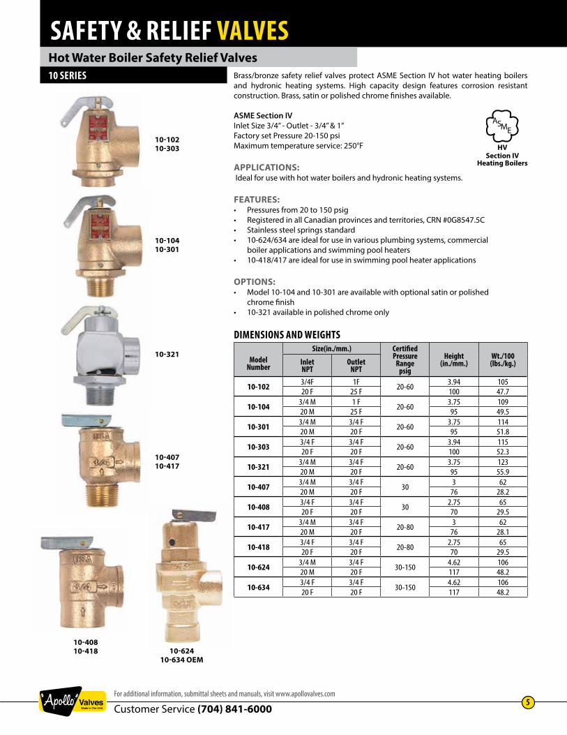
Hot Water Boiler Safety Relief Valves10 SERIES Brass/bronze safety relief valves protect ASME Section IV hot water heating boilers
and hydronic heating systems. High capacity design features corrosion resistant construction. Brass, satin or polished chrome finishes available.
ASME Section IVInlet Size 3/4” - Outlet - 3/4” & 1”Factory set Pressure 20-150 psiMaximum temperature service: 250°F
APPLICATIONS: Ideal for use with hot water boilers and hydronic heating systems.
FEATURES:• Pressures from 20 to 150 psig• Registered in all Canadian provinces and territories, CRN #0G8547.5C• Stainless steel springs standard • 10-624/634 are ideal for use in various plumbing systems, commercial boiler applications and swimming pool heaters• 10-418/417 are ideal for use in swimming pool heater applications
OPTIONS:• Model 10-104 and 10-301 are available with optional satin or polished chrome finish• 10-321 available in polished chrome only
DIMENSIONS AND WEIGHTS
ModelNumber
Size(in./mm.) CertifiedPressure
Rangepsig
Height(in./mm.)
Wt./100(lbs./kg.)Inlet
NPTOutlet
NPT
10-102 3/4F 1F 20-60 3.94 10520 F 25 F 100 47.7
10-104 3/4 M 1 F 20-60 3.75 10920 M 25 F 95 49.5
10-301 3/4 M 3/4 F 20-60 3.75 11420 M 20 F 95 51.8
10-303 3/4 F 3/4 F 20-60 3.94 11520 F 20 F 100 52.3
10-321 3/4 M 3/4 F 20-60 3.75 12320 M 20 F 95 55.9
10-407 3/4 M 3/4 F 30 3 6220 M 20 F 76 28.2
10-408 3/4 F 3/4 F 30 2.75 6520 F 20 F 70 29.5
10-417 3/4 M 3/4 F 20-80 3 6220 M 20 F 76 28.1
10-418 3/4 F 3/4 F 20-80 2.75 6520 F 20 F 70 29.5
10-624 3/4 M 3/4 F 30-150 4.62 10620 M 20 F 117 48.2
10-634 3/4 F 3/4 F30-150
4.62 10620 F 20 F 117 48.2
10-62410-634 OEM
10-10210-303
10-10410-301
10-321
10-40710-417
10-40810-418
Section IVHeating Boilers
ASME
HV

SAFETY & RELIEF VALVES
Customer Service (704) 841-60006
www.apollovalves.com
Hot Water Boiler Safety Relief Valves
US Customary Units Btu/Hr.
Model No. 10-10210-104
10-30110-303 10-321 10-407
10-40810-41710-418
10-62410-634
Set Pressure psig5* - 225,000 175,000 - - -
10* - 295,000 230,000 - - -15 - 365,000 285,000 - - -20 545,000 420,000 325,000 - 377,000 -25 625,000 485,000 375,000 - 427,000 -30 710,000 550,000 425,000 535,000 477,000 68900035 790,000 610,000 475,000 - 532,000 76900040 870,000 675,000 525,000 - 587,000 84800045 955,000 740,000 575,000 - 642,000 928,00050 1,035,000 805,000 625,000 - 697,000 1,007,00055 1,115,000 870,000 675,000 - 752,000 1,087,00060 1,200,000 935,000 725,000 - 807,000 1,166,00065 - - - - 862,000 1,246,00070 - - - - 917,000 1,325,00075 - - - - 972,000 1,405,00080 - - - - 1,027,000 1,484,00085 - - - - - 1,564,00090 - - - - - 1,643,00095 - - - - - 1,723,000
100 - - - - - 1,802,000105 - - - - - 1,882,000110 - - - - - 1,961,000115 - - - - - 2,041,000120 - - - - - 2,120,000125 - - - - - 2,199,000130 - - - - - 2,279,000135 - - - - - 2,358,000140 - - - - - 2,438,000145 - - - - - 2,517,000150 - - - - - 2,597,000
* Pressure settings below 15 psi are non-ASME Code.
Metric Units Kcal/Hr.
Model No. 10-10210-104
10-30110-303 10-321 10-407
10-40810-41710-418
10-62410-634
Set Pressure barg0.34 - 57 44 - - -0.69 - 74 58 - - -1.03 92 72 - - -1.38 137 106 82 - 95 -1.72 158 122 95 - 108 -2.07 179 139 107 135 120 1742.41 199 154 120 - 134 1942.76 219 170 132 - 148 2143.10 241 187 145 - 162 2343.45 261 203 158 - 176 2543.80 281 219 170 - 190 2744.14 303 236 183 - 204 2944.48 - - - - 217 3144.83 - - - - 231 3345.17 - - - - 245 3545.51 - - - - 259 3745.86 - - - - - 3946.20 - - - - - 4146.55 - - - - - 4356.89 - - - - - 4547.24 - - - - - 4757.58 - - - - - 4957.93 - - - - - 5158.27 - - - - - 5358.62 - - - - - 5558.96 - - - - - 5759.31 - - - - - 5959.65 - - - - - 615
10.00 - - - - - 63510.34 - - - - - 655
ASME SECTION IV HOT WATERBritish thermal units per hour (Kilocalories per hour) at 10% overpressure. National Board Certified. Ratings are 90% of actual.
ORDERING CODE:Use two-digit suffix number to indicate set pressure and body finish.Suffix for 10-624 / 10-634 models is actual set pressure in psig.
P/N SUFFIX KEYSet
Pressurepsig
Exterior FinishPlain Brass
Satin Chrome
PolishedChrome
20 -02 -41 -6722 -03 -42 -6825 -04 -43 -6930 -05 -44 -7035 -06 -45 -7140 -07 -46 -7243 -08 -47 -7345 -09 -48 -7450 -10 -49 -7555 -11 -50 -7660 -12 -51 -7765 -1370 -1475 -1580 -16
10 SERIES
EXAMPLE:10-301-443/4” 10-301 set @ 30 psig, satin chrome finish.10-624-1253/4” 10-624 set @ 125 psig (plain bronze finish only)
NOTE: • Model 10-321 available in polished chrome finish only. • All other models are furnished with plain bronze finish. • Model 10-104 and 10-301 available with optional satin or polished chrome finish.

SAFETY & RELIEF VALVES
Customer Service (704) 841-6000For additional information, submittal sheets and manuals, visit www.apollovalves.com
7
OEM Style Steam Safety Relief Valves10-322 AND 10-512 SERIES National Board capacity-certified safety valves; brass body with optional satin or
polished chrome finish. Protects against excess pressure from thermal expansion and steam caused by failure of Btu input controls.
ASME Section VIIISizes 1/2” and 3/4”Factory set pressures 15 to 60 psig@312˚F maxNational Board Certified Capacity
APPLICATIONS: Ideally suited for OEM applications such as steam carpet and jewelry cleaners, autoclaves, sterilizers, commercial pressure cookers, steam jacketed kettles, dental equipment, coffee makers and similar equipment.
FEATURES:• Stainless steel springs • Small physical size• Discharge capacities to 725 lbs./hr. • Soft seating for exceptional seat tightness• Pressure settings 15 to 60 psig • 10-322 in polished chrome only (10-322-P)• CRN OG8547.5C, registered in all Canadian provinces and territories• More descriptive model numbering system
OPTIONS: (Model 10-512 Only)• Satin or polished chrome finish • Stainless steel wetted trim • BSP pipe connections• CE/PED compliance
DIMENSIONS AND WEIGHTS
ModelNumber
Size (in./mm.) SetPressure
Rangepsig
Height(in./mm.)
Wt./100(lbs./kg.)Inlet
NPTOutlet
NPT
10-322 3/4 M 3/4 F 20-60 3.75 12820 20 95 58.2
10-512 1/2 M 1/2 F15-60
2.62 58 15 15 67 26.4
10-512
10-322
P/N SUFFIX KEYSet
Pressurepsig
*Certified Capacities10.322lbs.hr.
15.512lbs.hr
15 - 15120 325 17825 375 20530 425 23235 475 25840 525 28545 575 31250 625 33955 675 36660 725 392
* ASME (UV) Rating – 90% of actual capacity at 10% accumulation. Capacity in lbs. of saturated steam per hour.
EXAMPLE:10-322-P-203/4” 10-322 set @ 20 psig, polished chrome finish.
NOTE: • Model 10-322 available in polished chrome finish only. • Valves may be set for any pressure between 15 and 60 psig.
MODEL NUMBERING SYSTEM10 - X -X -XX -XMODEL AND SIZE (IN.) FINISH SET PRESSURE OPTIONS512 = 1/2 x 1/2 B = Plain Brass Set Pressure in PSIG B = BSPP connections322 = 3/4 x 3/4 S = Satin Chrome (2 Digits) CE = PED/CE
P = Polished Chrome S = Stainless Steel trimV = Viton® SeatX = Blank Outlet not threaded
Section VIIIPressure Vessels
ASME
UV

SAFETY & RELIEF VALVES
Customer Service (704) 841-60008
www.apollovalves.com
OEM Style Steam Safety Relief Valves10-322 SERIES
10-512 SERIES
10-322 MATERIALSItem Component Material
1 Nozzle Brass ASTM B-162 Body Brass ASTM B-163 Nameplate Aluminum4 Drive Screw Steel, Zinc Plated5 Handle Steel, Zinc Plated6 Cotter Pin Steel, Zinc Plated7 Stem Brass ASTM B-168 Spring Stainless Steel9 Spring Washer Brass ASTM B-16
10 Disc Brass ASTM B-1611 Seat Teflon Faced EPDM12 Washer Brass ASTM B-16
10-512 MATERIALSItem Component Material
1 Nozzle Brass ASTM B-162 Body Brass ASTM B-163 Nameplate Aluminum4 Drive Screw Steel, Zinc Plated5 Pull Ring Steel, Zinc Plated6 Cap Brass ASTM B-167 Disc Assembly Brass, Silicone8 Spring Stainless Steel9 Spring Washer Brass ASTM B-16
Model 10-512 available with optional stainless steel wetted trim. Nozzle, disc holder and disc washer are type 316 stainless steel.
6 7
8
9
10
11
12
5
4
3
2
1
5
2
9
6
8
4
3
7
1

SAFETY & RELIEF VALVES
Customer Service (704) 841-6000For additional information, submittal sheets and manuals, visit www.apollovalves.com
9
High Capacity Safety Relief Valves for Hot Water Heating Boilers10-600 SERIES High-capacity heating system valves with female inlet and standard or expanded
female outlet. Elevated seat for drainage of water away from seat area. Entire pressure range is National Board capacity certified.
ASME Section IVInlet Sizes 3/4” to 2”Factory set pressures from 15-160 psigMaximum temperature service 250°F
APPLICATIONS:Hot water heating boilers and hot water supply systems
FEATURES:• High Btu capacity rating• Silicone seat• Fabric reinforced molded diaphragm isolates spring from water at all times• Bronze body and spring cage• Registered in Canadian provinces and territories CRN #0G8547.5C• Protects against excessive water pressure due to failure of controls to regulate Btu input
DIMENSIONS AND WEIGHTS
ModelNumber
Size(in./mm.) CertifiedPressure
Rangepsig
Wt./100(lbs./kg.)
Dimensions (in./mm.)InletNPT
OutletNPT A B C D
10-604 3/4F 3/4F 15-160 232 1.03 5.25 1.62 1.5620 20 105.2 26 133 41 39
10-614 3/4F 1 F 15-160 226 1.03 5.25 1.72 1.5620 25 102.5 26 133 43 39
10-605 1F 1F 15-160 410 1.25 6.69 2.00 2.0025 25 185.9 31 169 50 50
10-615 1 F 1-1/4F 15-160 390 1.25 6.69 2.00 2.0025 32 176.9 31 169 50 50
10-606 1-1/4F 1-1/4F 15-160 795 1.25 8.37 2.47 2.6232 32 360.5 31 212 63 67
10-616 1-1/4F 1-1/2F 15-160 755 1.25 8.37 2.47 2.6232 40 342.4 31 212 63 67
10-607 1-1/2F 1-1/2F 15-160 1100 2.00 10.75 2.75 3.1240 40 498.9 50 273 69 79
10-617 1-1/2F 2F 15-160 1145 2.00 10.75 2.75 3.1240 50 519.3 50 273 69 79
10-608 2F 2F 15-160 2375 2.19 14.00 3.69 3.5050 50 1077.1 55 355 93 88
10-618 2F 2-1/2F15-160
2315 2.19 14.00 3.66 3.5050 65 1049.9 55 355 92 88
P/N SUFFIX KEYSet
Pressure psig
SuffixSet
Pressure psig
Suffix
15 -01 85 -1720 -02 90 -1822 -03 95 -1925 -04 100 -2030 -05 105 -2135 -06 110 -2240 -07 115 -2343 -08 120 -2445 -09 125 -2550 -10 130 -3055 -11 135 -3160 -12 140 -3265 -13 145 -3370 -14 150 -3475 -15 155 -3580 -16 160 -36
ORDERING CODE:Use two-digit suffix number to indicate Inlet x Outlet size and set pressure.
EXAMPLES:10-615-121”x 1-1/4” 10-610 set 60 psig10-608-052”x 2” 10-600 set 30 psig
A
B
CD
Section IVHeating Boilers
ASME
HV

SAFETY & RELIEF VALVES
Customer Service (704) 841-600010
www.apollovalves.com
US Customary Units Btu/Hr.
Model No. 10-6043/4 x 3/4
10-6051 x 1
10-6061-1/4 x 1-1/4
10-6071-1/2 x 1-1/2
10-6082 x 2
Set Pressure psig15 541,000 876,000 1,515,000 2,061,000 3,397,00020 636,000 1,030,000 1,782,000 2,424,000 3,996,00025 732,000 1,185,000 2,049,000 2,788,000 4,595,00030 827,000 1,339,000 2,316,000 3,151,000 5,193,00035 923,000 1,493,000 2,583,000 3,514,000 5,792,00040 1,018,000 1,648,000 2,850,000 3,878,000 6,391,00045 1,113,000 1,802,000 3,117,000 4,241,000 6,990,00050 1,209,000 1,956,000 3,384,000 4,604,000 7,589,00055 1,304,000 2,111,000 3,651,000 4,968,000 8,188,00060 1,399,000 2,265,000 3,918,000 5,331,000 8,786,00065 1,495,000 2,420,000 4,185,000 5,694,000 9,385,00070 1,590,000 2,574,000 4,453,000 6,058,000 9,984,00075 1,686,000 2,728,000 4,720,000 6,421,000 10,583,00080 1,781,000 2,883,000 4,987,000 6,784,000 11,182,00085 1,876,000 3,037,000 5,254,000 7,148,000 11,780,00090 1,972,000 3,192,000 5,521,000 7,511,000 12,379,00095 2,067,000 3,346,000 5,788,000 7,874,000 12,978,000
100 2,162,000 3,500,000 6,055,000 8,238,000 13,577,000105 2,258,000 3,655,000 6,322,000 8,601,000 14,176,000110 2,353,000 3,809,000 6,589,000 8,964,000 14,775,000115 2,449,000 3,963,000 6,856,000 9,327,000 15,373,000120 2,544,000 4,118,000 7,123,000 9,691,000 15,972,000125 2,639,000 4,272,000 7,390,000 10,054,000 16,571,000130 2,735,000 4,427,000 7,657,000 10,417,000 17,170,000135 2,830,000 4,581,000 7,924,000 10,781,000 17,769,000140 2,925,000 4,735,000 8,191,000 11,144,000 18,368,000145 3,021,000 4,890,000 8,458,000 11,507,000 18,966,000150 3,116,000 5,044,000 8,725,000 11,871,000 19,565,000155 3,212,000 5,199,000 8,992,000 12,234,000 20,164,000160 3,307,000 5,353,000 9,260,000 12,597,000 20,763,000
High Capacity Safety Relief Valves for Hot Water Heating Boilers10-600 SERIES
ASME SECTION IV HOT WATERBritish thermal units per hour (Kilocalories per hour) at 10% overpressure. National Board Certified. Ratings are 90% of actual.
10-600 MATERIALSItem Component Material
1 Body Bronze Alloy C844002 Seat Insert Brass ASTM B-163 Seat Silicone4 Disc Brass ASTM B-165 Diaphragm Fabric Reinforce EPDM6 Stem Nut Steel Plated7 Spacer Silicone8 Cap Bronze Alloy C844009 Spring PLAted ASTM A228
10 Spring Washer AISI 12L14 Steel11 Adj. Screw Brass ASTM B-1612 Nameplate Aluminum13 Lift Washer Steel Plated14 Handle Rivet Steel Plated15 Lift Handle Steel Plated16 Stem Nut Steel Plated17 Diaphragm Ret. Steel Plated
Metric Units Kcal/Hr.
Model No. 10-60420 x 20
10-60525 x 25
10-60632 x 32
10-60740 x 40
10-60850x 50
Set Pressure barg1.03 136 221 382 520 8571.38 160 260 449 611 1,0081.72 185 299 517 703 1,1592.07 209 351 584 795 1,3102.41 233 377 651 886 1,4612.76 257 416 719 978 1,6123.10 281 454 786 1,070 1,7633.45 305 493 853 1,161 1,9143.79 329 532 921 1,253 2,0654.14 353 571 988 1,344 2,2194.48 377 610 1,055 1,436 2,3674.83 401 649 1,123 1,528 2,5185.17 425 688 1,190 1,619 2,6695.51 449 727 1,258 1,711 2,8205.86 473 766 1,325 1,803 2,9716.20 497 805 1,393 1,894 3,1226.55 521 844 1,560 1,986 3,2736.89 545 883 1,527 2,076 3,4247.24 569 922 1,594 2,169 3,5757.58 593 961 1,662 2,261 3,7267.93 618 999 1,729 2,352 3,8778.27 642 1,039 1,796 2,444 4,0288.62 666 1,077 1,864 2,536 4,1798.96 690 1,116 1,931 2,627 4,3309.31 714 1,155 1,998 2,719 4,4819.65 738 1,194 2,066 2,811 4,632
10.00 762 1,233 2,133 2,902 4,78310.34 786 1,272 2,200 2,994 4,93410.69 810 1,311 2,268 3,085 5,08511.03 834 1,350 2,335 3,177 5,236
9
8
7
6
5
4
2
1
3
1415
16
11
10
13
12
17B
A
D C

SAFETY & RELIEF VALVES
Customer Service (704) 841-6000For additional information, submittal sheets and manuals, visit www.apollovalves.com
11
US Customary Units Btu/Hr.
Model No. 10-6143/4 x 1
10-6151 x 1-1/4
10-6161-1/4 x 1-1/2
10-6171-1/2 x 2
10-6182 x 2-1/2
Set Pressure psig15 635,000 1,027,000 1,777,000 2,417,000 3,984,00020 746,000 1,208,000 2,090,000 2,843,000 4,686,00025 858,000 1,389,000 2,403,000 3,270,000 5,389,00030 970,000 1,570,000 2,716,000 3,696,000 6,091,00035 1,082,000 1,751,000 3,030,000 4,122,000 6,793,00040 1,194,000 1,933,000 3,343,000 4,548,000 7,496,00045 1,306,000 2,114,000 3,656,000 4,974,000 8,198,00050 1,418,000 2,295,000 3,969,000 5,400,000 8,900,00055 1,529,000 2,476,000 4,283,000 5,826,000 9,603,00060 1,641,000 2,657,000 4,596,000 6,252,000 10,305,00065 1,753,000 2,838,000 4,909,000 6,679,000 11,007,00070 1,865,000 3,019,000 5,222,000 7,105,000 11,710,00075 1,977,000 3,200,000 5,535,000 7,531,000 12,412,00080 2,089,000 3,381,000 5,849,000 7,957,000 13,114,00085 2,201,000 3,562,000 6,162,000 8,383,000 13,817,00090 2,313,000 3,743,000 6,475,000 8,809,000 14,519,00095 2,424,000 3,924,000 6,788,000 9,235,000 15,221,000
100 2,536,000 4,105,000 7,101,000 9,661,000 15,924,000105 2,648,000 4,286,000 7,415,000 10,088,000 16,626,000110 2,760,000 4,468,000 7,728,000 10,514,000 17,328,000115 2,872,000 4,649,000 8,041,000 10,940,000 18,031,000120 2,984,000 4,830,000 8,354,000 11,366,000 18,733,000125 3,096,000 5,011,000 8,668,000 11,792,000 19,435,000130 3,207,000 5,192,000 8,981,000 12,218,000 20,138,000135 3,319,000 5,373,000 9,294,000 12,644,000 20,840,000140 3,431,000 5,554,000 9,607,000 13,070,000 21,543,000145 3,543,000 5,735,000 9,920,000 13,497,000 22,245,000150 3,655,000 5,916,000 10,234,000 13,923,000 22,947,000155 3,767,000 6,097,000 10,547,000 14,349,000 23,650,000160 3,879,000 6,278,000 10,860,000 14,775,000 24,352,000
Metric Units Kcal/Hr.
Model No. 10-61420 x 25
10-61525 x 32
10-61632 x 40
10-61740 x 50
10-61850 x 65
Set Pressure barg1.03 160 259 448 610 1,0051.38 188 305 527 717 1,1821.72 216 350 606 825 1,3592.07 245 396 645 932 1,5362.41 273 442 765 1,040 1,7132.76 301 488 843 1,147 1,8903.10 329 533 922 1,254 2,0673.45 358 579 932 1,362 2,2443.79 386 624 1,080 1,469 2,4224.14 414 670 1,159 1,577 2,5994.48 442 716 1,238 1,684 2,7764.83 470 761 1,317 1,792 2,9535.17 498 807 1,396 1,899 3,1305.51 527 827 1,475 2,007 3,3075.86 555 898 1,554 2,114 3,4856.20 583 944 1,633 2,222 3,6626.55 611 990 1,712 2,329 3,8396.89 640 1,035 1,791 2,437 4,0167.24 668 1,081 1,870 2,544 4,1937.58 696 1,127 1,949 2,652 4,3707.93 724 1,172 2,028 2,759 4,5478.27 752 1,218 2,107 2,866 4,7248.62 781 1,264 2,186 2,974 4,9018.96 809 1,309 2,265 3,081 5,0799.31 837 1,355 2,344 3,189 5,2569.65 865 1,401 2,423 3,296 5,433
10.00 893 1,446 2,502 3,404 5,61010.34 922 1,492 2,581 3,511 5,78710.69 950 1,538 2,660 3,619 5,96411.03 978 1,583 2,739 3,726 6,141
High Capacity Safety Relief Valves for Hot Water Heating Boilers
ASME SECTION IV HOT WATERBritish thermal units per hour (Kilocalories per hour) at 10% overpressure. National Board Certified. Ratings are 90% of actual.
10-610 SERIES

SAFETY & RELIEF VALVES
Customer Service (704) 841-600012
www.apollovalves.com
Low Pressure Steam Heating Boiler Safety Valves12-200 SERIES Medium capacity safety valves protect ASME Section IV low pressure steam heating
boilers. Cast bronze, full nozzle design features PTFE faced elastomer soft seating for dependable operation. Ideal for OEM applications.
ASME Section IVSizes 2, 2-1/2” and 3”Factory set pressures 5-15 psi
APPLICATIONS:Medium and large commercial and industrial steam heating and processing boilers.
FEATURES:• All bronze construction • PTFE-coated O-ring seat seal• 3/8” NPT side tapping for drain • Rust-proofed steel spring• Top guided, high capacity design• Registered in all Canadian provinces and territories, CRN #0G8547.5C• National Board certified at 15 psig
DIMENSIONS AND WEIGHTS
ModelNumber
Size (in./mm.)Wt./Ea.
(lbs./kg.)
Dimensions (in./mm.)InletNPT
OutletNPT A B C D
12-205 2M 2F 5.1 6.00 3.75 2.62 4.0050 50 2.3 152 95 67 102
12-206 2-1/2M 2-1/2F 8.4 8.50 5.25 3.06 4.0065 65 3.8 216 133 78 102
12-208 3M 3F 11.6 9.50 6.00 3.75 4.0080 80 5.3 241 152 95 102
NOTE: See Capacities page 15
10-512 MATERIALSItem Component Material
1 Nozzle Bronze ASTM B5842 Body Bronze ASTM B5843 O-ring Teflon Coated EPDM4 Drive Screw AISI 1010 Plated CR Steel5 Nameplate Aluminum6 Handle Assembly Steel, Plated7 Disc Brass ASTM B-16
10 Stem Brass ASTM B-1611 Spring Stainless Steel12 Spr. Washer AISI 1010 Plated CR steel13 Stem Nut Brass ASTM B-1614 Retainer Ring Brass ASTM B-1615 Guide Brass ASTM B-16
P/N SUFFIX KEYSet Pressure
psig Suffix
5 -036 -048 -05
10 -0612 -0715 -08
ORDERING CODE:Use two-digit suffix number to indicate set pressure and body finish.
EXAMPLE:12-205-082” 12 Series set 15 psig
6
15
2
5
4
3
1
13
A
B
D C
6
10
11
12
7
14
Section IVHeating Boilers
ASME
HV
SAFETY & RELIEF VALVES
Customer Service (704) 841-6000For additional information, submittal sheets and manuals, visit www.apollovalves.com
13
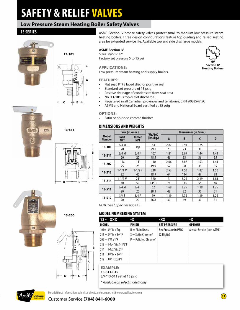
ASME Section IV bronze safety valves protect small to medium low pressure steam heating boilers. Three design configurations feature top guiding and raised seating area for extended service life. Available top and side discharge models.
ASME Section IVSizes 3/4”-1-1/2”Factory set pressure 5 to 15 psi
APPLICATIONS:Low pressure steam heating and supply boilers.
FEATURES:• Flat seat, PTFE faced disc for positive seal• Standard set pressure of 15 psig• Positive drainage of condensate from seat area• No. 13-101 is top outlet discharge• Registered in all Canadian provinces and territories, CRN #0G8547.5C• ASME and National Board certified at 15 psig
OPTIONS:• Satin or polished chrome finishes
DIMENSIONS AND WEIGHTS
ModelNumber
Size (in./mm.)Wt./100(lbs./kg.)
Dimensions (in./mm.)InletNPT
OutletNPT A B C D
13-101 3/4 M Top 64 2.87 0.94 1.25 –20 29.0 73 23 31 –
13-211 3/4 M 3/4 F 107 1.81 3.69 1.44 1.4120 20 48.5 46 93 36 35
13-202 1 M 1 F 110 2.06 3.87 1.53 1.4125 25 49.9 52 98 39 35
13-213 1-1/4 M 1-1/2 F 218 2.53 4.50 1.87 1.5032 40 98.9 64 114 47 38
13-214 1-1/2 M 2 F 320 3 5.25 2.19 1.8140 50 145.1 76 133 55 46
13-511 3/4 M 3/4 F 62 1.69 3.25 1.19 1.2520 20 28.1 42 82 30 31
13-512 3/4 F 3/4 F 59 1.19 2.75 1.19 1.2520 20 26.8 30 69 30 31
NOTE: See Capacities page 15
Low Pressure Steam Heating Boiler Safety Valves13 SERIES
13-101
13-511
13-200
EXAMPLE:13-511-B153/4” 13-511 set at 15 psig
* Available on select models only
MODEL NUMBERING SYSTEM13 - XXX -X -XX -XMODEL FINISH SET PRESSURE OPTIONS101= 3/4”M x Top B = Plain Brass Set Pressure in PSIG A = Air Service (Non-ASME)211 = 3/4”M x 3/4”F S = Satin Chrome* (2 Digits)202 = 1”M x 1”F P = Polished Chrome*213 = 1-1/4”M x 1-1/2”F214 = 1-1/2”M x 2”F511 = 3/4”M x 3/4”F512 = 3/4” F x 3/4”F
A
BC
A
D
B
C
CD
A
B
Section IVHeating Boilers
ASME
HV

SAFETY & RELIEF VALVES
Customer Service (704) 841-600014
www.apollovalves.com
Low Pressure Steam Heating Boiler Safety Valves14-200 SERIES ASME Section IV
Factory set pressures from 5 to 15 psig. Sizes 2”, 2-1/2” and 3”.
APPLICATIONS:The 14 Series is an ASME Section IV high capacity steam safety valve for use with medium and large size commercial and industrial heating boilers.
FEATURES:• One piece body, all bronze construction• Rust proofed steel spring• Chrome plated seat, PTFE coated disc• PTFE coated EPDM O-ring for positive seal • 3/8” NPT side tapping for drain connection• Valves are capacity certified by the National Board at 15 psig only, in accordance with ASME Boiler and Pressure Vessel Code Section IV • Registered in all Canadian provinces and territories, CRN #0G8547.5C
OPTIONS:• Test gag available to prevent the valve from opening during hydrostatic testing of the boiler. To specify gag option, add “G” to suffix.
DIMENSIONS AND WEIGHTS
ModelNumber
Size (in./mm.)Wt./Ea.
(lbs./kg.)
Dimensions (in./mm.)InletNPT
OutletNPT A B C D
14-205 2M 2F 8.4 3.00 7.12 3.12 4.0050M 50F 3.8 76 181 79 101
14-206 2-1/2M 2-1/2F 13.0 3.50 8.25 3.50 4.0065M 65F 5.9 88 209 88 101
14-207 3M 3F 17.0 4.12 9.37 3.87 4.0080M 80F 7.7 104 238 98 101
NOTE: See Capacities page 15
ORDERING CODE:Use model number and two digit suffix number to indicate size and set pressure.
P/N SUFFIX KEYSet Pressure
psig Suffix
5 -036 -048 -05
10 -0612 -0715 -08
EXAMPLE:14-206-08 2-1/2” valve set at 15 psi
Note: • ASME IV and NB certified capacities at 15 psi only • Valves may be set for any pressure between 5 and 15 psi. Consult factory for set pressures not listed. • To specify test gag option add “G” to suffix.
D C
B
A
Section IVHeating Boilers
ASME
HV

SAFETY & RELIEF VALVES
Customer Service (704) 841-6000For additional information, submittal sheets and manuals, visit www.apollovalves.com
15
Low Pressure Steam Heating Boiler Safety Valves
CAPACITIES – ASME SECTION IV STEAMPounds per hour (Kilograms per hour) saturated steam at 33-1/3% overpressure. National Board Certified. Ratings are 90% of actual.
US Customary Units Lbs./Hr.
Model No.(in.)
12-2052 x 2
12-2062-1/2 x 2-1/2
12-2083 x 3
13-1013/4
13-2021 x 1
13-2113/4 x 3/4
13-2131-1/4 x 1-1/2
13-2141-1/2 x 2
13-51113-512
3/4 x 3/414-205
2 x 214-206
2-1/2 x 2-1/214-207
3 x 3
Set Pressure psig5* 1,439 2,043 2,855 333 374 290 699 1,106 213 1,815 2,695 3,944
10* 1,969 2,786 3,478 372 509 383 950 1,503 310 2,483 3,686 5,39415 2,500 3,529 4,100 410 643 475 1,200 1,900 407 3,150 4,676 6,843
Metric Units Kg./Hr.
Model No.(mm.)
12-20550 x 50
12-20665 x 65
12-20880 x 80
13-10120
13-20225 x 25
13-21120x20
13-21332 x 40
13-21440 x 50
13-51113-51220 x 20
14-20550 x 50
14-20665 x 65
14-20780 x 80
Set Pressure barg0.34 653 927 1,295 151 170 131 317 502 97 823 1,222 1,7890.69 893 1,264 1,577 169 231 174 431 682 141 1,126 1,672 2,4471.03 1,134 1,601 1,860 186 292 215 544 862 185 1,429 2,121 3,103
*ASME Section IV and NB certified capacities at 15 psi only. Valves may be set for any pressure between 5 and 15 psi. Consult factory for set pressures not listed.
12, 13 AND 14-200 SERIES

SAFETY & RELIEF VALVES
Customer Service (704) 841-600016
www.apollovalves.com
Low Pressure Air Relief Valves14-400 AND 14-500 SERIES High volume air relief valves designed for low pressure/high volume air and gas
service. Rugged bronze construction features elastomer soft seating and TFE coated discs for dependable operation.
Inlet sizes 2”, 2 1/2” and 3” Factory set pressures 4 to 22 psig @ 400˚F max.
APPLICATIONS:• Non-ASME code air and gas service• Low pressure, high volume blowers and compressors• Bulk hauling tanks, trailers and rail cars• Powdered solids / bulk handling• Pneumatic conveying equipment
FEATURES:• Vibration resistant soft seat is standard• Stainless steel spring• One piece corrosion resistant bronze body design• High flow “top-guided” design
OPTIONS:• Model 14-400 with test lever• Model 14-500 with plain cap, weather resistant sealed body
AIR RELIEF CAPACITY:See page 19
DIMENSIONS AND WEIGHTSModel
Number Size (in./mm.)Dimensions (in./mm.) Wt./Ea.
(lbs./kg.)A B C
14-X05 2 x 2 3 6-1/2 3-1/8 8.450M x 50F 76 165 79 3.81
14-X06 2-1/2 x 2-1/2 3-1/2 7-5/8 3-1/2 12.565M x 65F 89 194 89 5.7
14-X07 3 x 3 4-1/8 8-3/4 3-7/8 17.080M x 80F 105 222 98 7.7
14-400W/LIFT LEVER
14-500PLAIN CAP
EXAMPLES:14-406 122-1/2” 14 Series air relief valve set at 12 psig, with lift lever14-505-082” air relief valve set at 8 psig, with sealed cap
MODEL NUMBERING SYSTEM14-400/500 Series Air Relief Valves
14 -X -XX -X
SERIES NUMBER BODY/CAP STYLEAND SERVICE INLET CONNECTION RELIEF PRESSURE
14 = Base Model No. 4 = Air Relief, with Test Lever 05 = 2” NPT Set Pressure in PSIG 5 = Air Relief, Plain Cap 06 = 2 1/2” NPT (2 Digits)
07 = 3” NPT
B
C
A
B
C
A

SAFETY & RELIEF VALVES
Customer Service (704) 841-6000For additional information, submittal sheets and manuals, visit www.apollovalves.com
17
Vacuum Relief Valves14-600 SERIES High flow vacuum relief valves feature one piece cast bronze bodies. Teflon coated
discs and elastomer soft seating provide accurate and dependable operation.
Connection sizes 2”, 2 1/2” and 3” Relief settings 8” to 30” Hg @ 400˚F max.
APPLICATIONS:• High volume vacuum systems• Bulk hauling tanks and trailers• Powdered solids / bulk handling• Pneumatic conveying equipment
FEATURES:• Weather resistant construction• Elastomer soft seat is vibration resistant• Stainless steel spring• One piece corrosion resistant bronze body design• High capacity “top-guided” design • TFE / chrome plated internals
VACUUM AIR RELIEF CAPACITY:See page 19
DIMENSIONS AND WEIGHTSModel
Number Size (in./mm.)Dimensions (in./mm.) Wt./Ea.
(lbs./kg.)A B C
14-605 2 x 2 3 6-1/2 3-1/8 8.450M x 50F 76 165 79 3.81
14-606 2-1/2 x 2-1/2 3-1/2 7-5/8 3-1/2 11.865M x 65F 89 194 89 5.4
14-607 3 x 3 4-1/8 8-3/4 3-7/8 16.380M x 80F 105 222 98 7.4
14-600
EXAMPLE:14-607-V143” Vacuum relief valve set at 14 Hg”
MODEL NUMBERING SYSTEM14 -6 -0X -VXX
SERIES NUMBER BODY/CAP STYLEAND SERVICE INLET CONNECTION RELIEF PRESSURE
14 = Base Model No. 6 = Vacuum Relief 05 = 2” NPT Vacuum Relief Setting, HG “V” Prefix + Inches Mercury (“V” + 2 Digits)
06 = 2 1/2” NPT07 = 3” NPT
B
C
A
Connect vacuum
source here

SAFETY & RELIEF VALVES
Customer Service (704) 841-600018
www.apollovalves.com
Low Pressure Air and Vacuum Relief Valves14-400, 14-500 AND 14-600 SERIES
MATERIALSItem Component Material
1 Nameplate Aluminum2 Drivescrews (2) Steel (Plated)3 Spring Stainless Steel4 Adjusting Screw Brass ASTM B-165 Cap Screw (4) Steel (Plated)6 Spring Washer Brass ASTM B-167 Cap Bronze ASTM B-5848 Seat-O-Ring Silicone9 Seat Insert Brass ASTM B-16
10 Disc Bronze ASTM B-58411 Body Bronze ASTM B-58412 Friction Ring EPDM13 Stem Nut Brass ASTM B-1614 Stem Brass ASTM B-1615 Retaining Ring Steel (Plated)16 Lift Washer Steel (Plated)17 Lift Lever Steel (Plated)18 Roll Pin Steel (Plated)19 Plug Brass ASTM B-1620 Plug Brass ASTM B-1621 Cap Seal O-Ring Silicone
14-400
14-500 & 14-600
5
1716 18
4
2
11
3
6
13
14
15
8
10
9
7
12
5
712
20
11
19
14
8
221
1
6
4
313
15
10
9

SAFETY & RELIEF VALVES
Customer Service (704) 841-6000For additional information, submittal sheets and manuals, visit www.apollovalves.com
19
Air Relief Valves14-400 AND 14-500 SERIES
US Customary Units SCFM Air
Ordering Suffix
Model No.
Size (in.)Area (in.2)
14-40514-505
2 x 22.238
14-40614-506
2-1/2 x 2-1/23.339
14-40714-507
3 x 35.155
Set Pressure psig-04 4 615 914 1338-05 5 651 967 1415-06 6 687 1020 1492-07 7 722 1072 1569-08 8 758 1125 1646-09 9 793 1178 1723-10 10 829 1231 1801-11 11 864 1283 1878-12 12 900 1336 1955-13 13 935 1389 2032-14 14 971 1441 2109-15 15 1006 1494 2186-16 16 1041 1547 2263-17 17 1076 1600 2340-18 18 1111 1653 2417-19 19 1146 1706 2494-20 20 1181 1756 2571-21 21 1216 1809 2648-22 22 1252 1861 2725
Metric Units Nm3/Hr. AirModel No.
Size (mm.)Area (cm2)
14-40514-50550 x 5014.438
14-40614-50665 x 6521.544
14-40714-50780 x 8033.259
Set Pressure barg.28 988 1469 2151.34 1046 1554 2275.41 1104 1639 2398.48 1161 1724 2522.55 1218 1809 2646.62 1275 1893 2770.69 1332 1978 2894.76 1389 2063 3018.83 1446 2147 3142.90 1503 2232 3266.97 1560 2317 3390
1.03 1617 2402 35141.10 1673 2487 36381.17 1730 2572 37611.24 1786 2657 38851.31 1842 2742 40091.38 1899 2823 41331.45 1955 2907 42571.52 2012 2992 4381
NON-CODE AIR RELIEF CAPACITIESStandard cubic feet per minute (Normalized cubic meters per hour) of air at 10% overpressure.
14-600 SERIES
US Customary Units SCFM Air
Ordering Suffix
Model No.Size (in.)
Area (in.2)
14-6052 x 2
2.238
14-6062-1/2 x 2-1/2
3.339
14-6073 x 3
5.155Relief Setting (in. Hg)
V08 8 395 600 865V09 9 405 618 890V10 10 415 635 915V11 11 421 642 927V12 12 426 649 939V13 13 430 653 943V14 14 430 653 943V15 15 430 653 943V20 20 430 653 943V25 25 430 653 943V30 30 430 653 943
Metric Units Nm3/Hr. AirModel No.Size (mm.)Area (cm2)
14-60550 x 5014.438
14-60665 x 6521.544
14-60780 x 8033.259
Relief Setting (mm. Hg)203 635 964 1390229 651 993 1431254 667 1021 1471279 676 1479 2132305 685 1043 1509330 691 1050 1516356 691 1050 1516381 691 1050 1516508 691 1050 1516635 691 1050 1516762 691 1050 1516
VACUUM AIR RELIEF CAPACITY.Standard cubic feet per minute (normalized cubic meters per hour) of air at 10% overpressure.

SAFETY & RELIEF VALVES
Customer Service (704) 841-600020
www.apollovalves.com
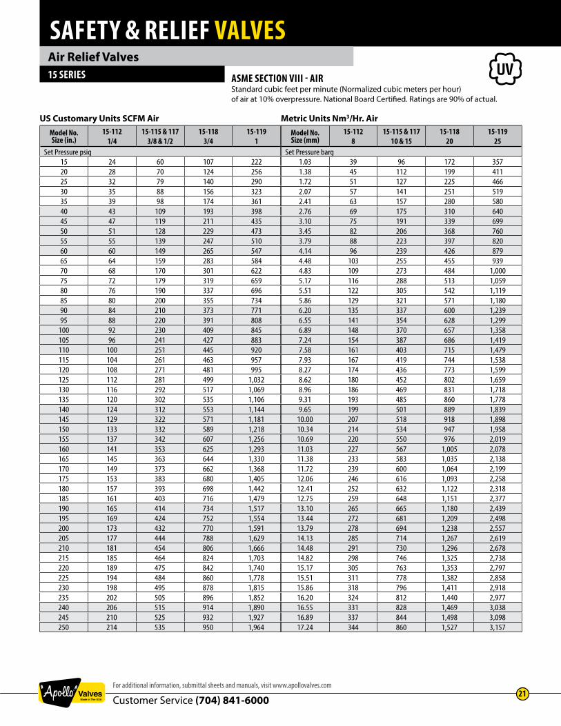
Air Relief Valves15 SERIES Rugged design 15 Series air relief valves provide dependable overpressure protection at
an economical price. Top guided design features brass construction and resilient seating for superior performance. Widely used by OEM’s and for aftermarket replacement.
ASME Section VIIISizes 1/4” to 1”Factory set pressures from 15 to 250 psiMaximum Temp. 325˚F
APPLICATIONS:Ideal for a wide range of air and inert gas applications including compressors, intercoolers, dryers, receivers, control and instrument air lines, and pressurized systems and equipment.
FEATURES: • National Board certified 15 psig through 250 psig • Stainless steel springs• Viton O-ring seat • Registered in all Canadian provinces and territories: CRN #0G8547.5C• ASTM B16 Brass Body• RoHS Compliant Materials• European pressure equipment directive compliant option (CE/PED)
DIMENSIONS AND WEIGHTSModel
NumberInlet
Size (in./mm.)Dimensions (in./mm.) Wt./100
(lbs./kg.)A B
15-112 1/4 NPT 2.62 0.78 18.58 66 20 8.4
15-115 3/8 NPT 3.25 1.12 42.210 82 28 19.2
15-117 1/2 NPT 3.37 1.12 45.315 85 28 20.6
15-118 3/4 NPT 4.06 1.21 5820 105 30 26.4
15-119 1 NPT 5.12 1.87 15325 130 47 69.5
MATERIALSItem Component Material
1 Nozzle ASTM B-16 Brass2 Body ASTM B-16 Brass3 Nameplate Aluminum4 Pull Ring Pltd. AISI 1018 CRS5 Disc/Stem ASTM B-16 Brass6 Seat Viton7 Cap ASTM B-16 Brass8 Spring ASTM A-227 Steel9 Inst. Tag Paper
10 Lead Seal Lead
EXAMPLE:15 117 B 16515 Series set @ 165 psig.
MODEL NUMBERING SYSTEM15-XXX -X -XXX -XXMODEL AND SIZE (IN.) FINISH SET PRESSURE OPTIONS112 = 1/4 NPT B = Plain Brass Set Pressure in PSIG CE = PED/CE115 = 3/8 NPT Q = Performance
(Calibration) Test Reports
117 = 1/2 NPT118 = 3/4 NPT119 = 1 NPT
A
B
7
10
4
8
5
6
9
1
2
3
Section VIIIPressure Vessels
ASME
UV
SAFETY & RELIEF VALVES
Customer Service (704) 841-6000For additional information, submittal sheets and manuals, visit www.apollovalves.com
21
Air Relief Valves15 SERIES
US Customary Units SCFM AirModel No.Size (in.)
15-1121/4
15-115 & 1173/8 & 1/2
15-1183/4
15-1191
Set Pressure psig15 24 60 107 22220 28 70 124 25625 32 79 140 29030 35 88 156 32335 39 98 174 36140 43 109 193 39845 47 119 211 43550 51 128 229 47355 55 139 247 51060 60 149 265 54765 64 159 283 58470 68 170 301 62275 72 179 319 65980 76 190 337 69685 80 200 355 73490 84 210 373 77195 88 220 391 808
100 92 230 409 845105 96 241 427 883110 100 251 445 920115 104 261 463 957120 108 271 481 995125 112 281 499 1,032130 116 292 517 1,069135 120 302 535 1,106140 124 312 553 1,144145 129 322 571 1,181150 133 332 589 1,218155 137 342 607 1,256160 141 353 625 1,293165 145 363 644 1,330170 149 373 662 1,368175 153 383 680 1,405180 157 393 698 1,442185 161 403 716 1,479190 165 414 734 1,517195 169 424 752 1,554200 173 432 770 1,591205 177 444 788 1,629210 181 454 806 1,666215 185 464 824 1,703220 189 475 842 1,740225 194 484 860 1,778230 198 495 878 1,815235 202 505 896 1,852240 206 515 914 1,890245 210 525 932 1,927250 214 535 950 1,964
ASME SECTION VIII - AIRStandard cubic feet per minute (Normalized cubic meters per hour) of air at 10% overpressure. National Board Certified. Ratings are 90% of actual.
Metric Units Nm3/Hr. AirModel No.Size (mm)
15-1128
15-115 & 11710 & 15
15-11820
15-11925
Set Pressure barg1.03 39 96 172 3571.38 45 112 199 4111.72 51 127 225 4662.07 57 141 251 5192.41 63 157 280 5802.76 69 175 310 6403.10 75 191 339 6993.45 82 206 368 7603.79 88 223 397 8204.14 96 239 426 8794.48 103 255 455 9394.83 109 273 484 1,0005.17 116 288 513 1,0595.51 122 305 542 1,1195.86 129 321 571 1,1806.20 135 337 600 1,2396.55 141 354 628 1,2996.89 148 370 657 1,3587.24 154 387 686 1,4197.58 161 403 715 1,4797.93 167 419 744 1,5388.27 174 436 773 1,5998.62 180 452 802 1,6598.96 186 469 831 1,7189.31 193 485 860 1,7789.65 199 501 889 1,839
10.00 207 518 918 1,89810.34 214 534 947 1,95810.69 220 550 976 2,01911.03 227 567 1,005 2,07811.38 233 583 1,035 2,13811.72 239 600 1,064 2,19912.06 246 616 1,093 2,25812.41 252 632 1,122 2,31812.75 259 648 1,151 2,37713.10 265 665 1,180 2,43913.44 272 681 1,209 2,49813.79 278 694 1,238 2,55714.13 285 714 1,267 2,61914.48 291 730 1,296 2,67814.82 298 746 1,325 2,73815.17 305 763 1,353 2,79715.51 311 778 1,382 2,85815.86 318 796 1,411 2,91816.20 324 812 1,440 2,97716.55 331 828 1,469 3,03816.89 337 844 1,498 3,09817.24 344 860 1,527 3,157

SAFETY & RELIEF VALVES
Customer Service (704) 841-600022
www.apollovalves.com
General Purpose Pressure Relief Valves
16-200 SERIES Pressure relief valves relieve excess pressure in cold water supply systems, storage tanks, well pumps. Also suitable for air, oil and other non-hazardous liquids.
FEATURES:• Standard pressure settings from 50 to 175 psi• Cast bronze body, stainless steel springs• Silicone soft seat ensures seat tightness, extended service life• All valves are 100% factory tested• Maximum recommended service temperature 120˚F• Lead Free Option, Model 16LF is NSF/ANSI 372 Lead Free
DIMENSIONS AND WEIGHTSModel
Number LF ModelNumber
InletSize (in./mm.)
Dimensions (in./mm.) Wt./100(lbs./kg.)A B C
16-202 16LF-202 1/2 M X 1/2 F 1.41 2.12 1.00 3315 M x 15 F 36 54 25 15
16-203 16LF-203 3/4 M x 1/2 F 1.41 2.50 1.00 37.520 M x 15 F 36 63 25 17
Economical relief valves for general purpose non-code overpressure protection and bypass relief applications. Applications include liquid bypass or thermal expansion relief of well pumps, tanks, fire protection systems and all types of water or liquid piping systems. Not intended for steam service.
P/N SUFFIX KEYSet Pressure
psig Suffix
50 -0175 -02
100 -03125 -04150 -05175 -06
ORDERING CODE:Use two-digit suffix number to indicate set pressure and body finish.
16-200
EXAMPLE:16-202-031/2” model set @ 100 psi.
NOTE: • Valves may be set for any pressure between 30 and 180 psi. Consult factory for pressure settings not shown.
A
B
C

SAFETY & RELIEF VALVES
Customer Service (704) 841-6000For additional information, submittal sheets and manuals, visit www.apollovalves.com
23
General Purpose Liquid Relief Valves16-501 SERIES Adjustable relief valves protect equipment by providing low volume liquid relief or
bypass control. Excess volume may be discharged back to the low pressure source. Ideal for agricultural sprayers and simple commercial or industrial pressurized systems.
FEATURES:• Adjustable relief settings, in two ranges to 600 psi • Cast bronze body, stainless steel springs• Choice of Nitrile (Buna) or PTFE soft seats • Knurled locknut locks pressure adjustment• Viton stem seal, polypropylene body gasket• Maximum recommended service temperature 200˚F
DIMENSIONS AND WEIGHTSModel
NumberInlet Size (in./mm.)
ReliefRange
SeatMaterial
Dimensions (in./mm.) Wt./100(lbs./kg.)A B C
16-501-011/2 M X 1/2 F15 M x 15 F
50 - 250Nitrile
1.2933
4.12105
1.0025
6228
16-501-02 250 - 60016-501-25 50 - 250
PTFE16-501-60 250 - 600
16-501
A
B
C
16-50316-504
Calibrated pressure relief valve allows for in-line pressure adjustments without the need for a pressure gauge. Provides static overpressure protection for liquid filled systems such as well pumps, tanks, fire protection systems.
FEATURES:• Choice of 1/2” or 3/4” inlet connection• Factory preset at 100 psi • Pressure range 50 to 175 psi, calibrated in 25 psi increments• Cast bronze body, stainless steel spring• Silicone soft seat, EPDM cap seal • Maximum recommended service temperature 200˚F• Lead Free Option, Model 16LF is NSF/ANSI 372 Lead Free
DIMENSIONS AND WEIGHTSModel
Number LF ModelNumber
Inlet Size (in./mm.)
Dimensions (in./mm.) Wt./100(lbs./kg.)A B C
16-503-01 16LF-503-01 1/2 M X 1/2 F1.3133
3.4487
1.0025
3717
15 M x 15 F
16-504-01 16LF-504-01 3/4 M X 1/2 F20 M x 15 F
16-503 & 16-504 SERIES
A
B
C

SAFETY & RELIEF VALVES
Customer Service (704) 841-600024
www.apollovalves.com
Pressure Only Hot Water Relief Valves17-400 SERIES 17-400 series pressure only relief valves are engineered to protect against excessive
pressure buildup due to thermal expansion in hot water supply systems. Both models are CSA certified to ANSI Z21.22 “Relief Valves for Hot Water Supply Systems”. In addition the 17-402 is design certified to ASME Section IV for hot water relief.
Connection sizes 1/2” (model 17-401) and 3/4” (model 17-402)CSA certified to ANSI Z21.22 Pressure settings 75 through 150 psi @ 250˚F max.ASME Section IV Hot Water, model 17-402 only
APPLICATIONS:Model 17-401: overpressure protection of domestic tankless water heaters. Also ideal for protecting plumbing and well systems, small liquid filled vessels and similar equipment from thermal expansion or pressure surges.Model 17-402: as above plus suitable for ASME Section IV hot water heating and supply boilers and storage tanks.
FEATURES:• Cast bronze body, stainless steel springs• Soft seat for durability, extended service life• Conforms to HUD / FHA requirements• CSA certified to ANSI Z21.22• ASME Section IV hot water, model 17-402• CSA B-51, CRN 0G8547.5C
DIMENSIONS AND WEIGHTS
ModelNumber
Inlet Size (in./mm.)
CSA Capacity Rating
ASME Capacity Rating
Dimensions (in./mm.) Wt./100(lbs./kg.)A B C
17-401 1/2 M X 1/2 F 15,000 – 3.26 1.73 1.16 5715 M X 15 F 83 44 29 26
17-402 3/4 M X 3/4 F200,000 See table
below3.14 1.62 1.13 53
20 M X 20 F 80 41 29 24
ORDERING CODE:Use model number and two-digit suffix number to indicate size and set pressure.
17-400
EXAMPLES:17-401-031/2” model 17 set @ 125 psig.17-402-043/4” model 17 set @ 150 psig.
NOTE:
• Valves may be set for any pressure between 70 and 175 psi. Consult factory for pressure settings not shown.
• ASME Section IV certified model 17-402 only, pressure settings 75 to 150 psig.
B
A
C
P/N SUFFIX KEYSet
Pressurepsig
SuffixBtu/hr.
ASME Sec. IV17-402
75 -01 505,000100 -02 648,000125 -03 791,000150 -04 934,000160 -05 –
ASME
HV

SAFETY & RELIEF VALVES
Customer Service (704) 841-6000For additional information, submittal sheets and manuals, visit www.apollovalves.com
25
Water Heater T&P Relief Valves18C-400 AND 18C-402X SERIES Automatic temperature and pressure relief valves feature unique non-metallic coating
which protects the element against galvanic and electromechanical corrosion by isolating it from the heated water. This coating is electrostatically applied for uniform coverage, then thermobonded, resulting in optimum adhesion for extended service life.
CSA design certified at all settings to ANSI Z21.22. ASME Section IV rated at 125 and 150 psig settings for 3/4 NPT only.
APPLICATIONS:Temperature and pressure protection for hot water heaters and storage tanks.
FEATURES:• Meets HUD/FHA requirements• Cast bronze body, stainless steel spring• Rated 210°F maximum • Registered in all Canadian provinces and territories• ASME capacity certified to 500,000 Btu/hr.
OPTIONS:• Model 18C-402X features a body inlet extended 2” for insulated vessels.
DIMENSIONS AND WEIGHTS
ModelNumber
Size (in./mm.)
Element Length
(in./mm.)
CSA Capacity RatingBtu/HR
Dimensions (in./mm.)Wt./100(lbs./kg.)A B C
18C-401 1/2 M x 1/2 F 1.44, 3 & 8" 15,000 3.25 1.75 1.13 6415 M x 15 F 37, 76 & 200 83 44 29 29
18C-402 3/4 M x 3/4 F 1.44 95,000 3.25 1.75 1.13 6420 M x 20 F 37 83 44 29 29
18C-402 3/4 M x 3/4 F 3 & 8” 105,000 3.25 1.75 1.13 6420 M x 20 F 76 & 200 83 44 29 29
18C-402X 3/4 M x 3/4 F 3"105,000
4.51 2.97 1.13 7520 M x 20 F 76 115 75 29 34
P/N SUFFIX KEY - MODEL 18C-401Set Pressure
psigCoated Element Length (in.)
1.44 3125 -27 -29150 -28 -30
P/N SUFFIX KEY - MODEL 18C-402XSet Pressure
psigCoated Element
Length (in.)125 -39150 -38
P/N SUFFIX KEY - MODEL 18C-402Set
Pressurepsig
Coated Element Length (in.)
1.44 3 8125 -27 -29 -36150 -28 -30 -37175 -24
18C-400
EXAMPLE:18C-402-303/4” model 18C-402 set 150 psig with 3” element
EXAMPLE:18C-402X-383/4” model 18C-402X set 150 psig with 3” element
A
C
B
A
C
B
18C-402XEXTENDED SHANK ORDERING CODE:
Use model number and two-digit suffix number to indicate size and set pressure.
Section IVHeating Boilers
ASME
HV
Special statement regarding T&P Valves and compliance to the Lead Free requirements of the U.S. Safe Drinking Water Act.
Effective January 4th 2014 the SDWA requires that pipes, fittings or fixtures used to convey or dispense potable water must be lead free. Further clarification has been provided by the EPA in a document titled “Summary of the Reduction of Lead In Drinking Water Act and frequently Asked Questions”. The latest document can be viewed on our website: www.apollovalves.com/lead_free; click on the NEW EPA FAQ link.
FAQ #6 states that water heaters are covered by the Act and must comply. However most water heater OEM’s are certifying their heaters as complete assemblies using non-Lead Free T&P valves due to their relatively small wetted surface area.
FAQ #23 acknowledges this and states that replacement parts (including T&P valves) need not be lead free as long as the entire water heater with all installed components overall device would meet the Lead Free requirements of the Act.

SAFETY & RELIEF VALVES
Customer Service (704) 841-600026
www.apollovalves.com
Bronze High Capacity Commercial T&P Valves18C SERIES The Apollo® 18C-500 Series bronze automatic temperature and pressure relief valves are
used for high capacity protection of commercial hot water heaters and storage tanks.
FEATURES:• ASME Section IV certified capacity• 3/4” through 2” NPT connections• CSA Listed and certified to ANSI Z21.22• 125 and 150 psig set pressures at 210°F max• Coated element protects against corrosion• SS elements (1-1/2” and 2”)• ASME Section IV heating boilers• Canadian registration number CSA- 0G1438.6C
DIMENSIONS AND WEIGHTSPart
Number Size (in.) Element Length (in.) Inlet Type
CSA Capacity Rating Btu/HR
*ASME Cap. Rating
BTU/HR18C5113125 3/4” 2.69” M 185,000 1,619,00018C5113150 3/4” 2.69” M 185,000 1,912,00018C5115125 3/4” 4.38” M 205,000 1,619,00018C5115150 3/4” 4.38” M 205,000 1,912,00018C5118125 3/4” 7.56” M 205,000 1,619,00018C5118150 3/4” 7.56” M 205,000 1,912,00018C5123125 3/4” 2.88” F 185,000 1,619,00018C5123150 3/4” 2.88” F 185,000 1,912,00018C5125125 3/4” 4.56” F 205,000 1,619,00018C5125150 3/4” 4.56” F 205,000 1,912,00018C5128125 3/4” 7.75” F 205,000 1,619,00018C5128150 3/4” 7.75” F 205,000 1,912,00018C5213125 1” 3.06” M 500,000 1,825,00018C5213150 1” 3.06” M 500,000 2,155,00018C5215125 1” 4.75” M 500,000 1,825,00018C5215150 1” 4.75” M 500,000 2,155,00018C5225125 1” 4.75” F 750,000 3,070,00018C5225150 1” 4.75” F 750,000 3,625,00018C5228125 1” 8.13” F 750,000 3,070,00018C5228150 1” 8.13” F 750,000 3,625,00018C5314125 1-1/4” x 1” 3.97” M 750,000 3,070,00018C5314150 1-1/4” x 1” 3.97” M 750,000 3,625,00018C5424125 1-1/2” 4.13” F 1,200,000 5,125,00018C5424150 1-1/2” 4.13” F 1,200,000 6,050,00018C5513125 2” x 1-1/2” 3.25” M 1,200,000 5,125,00018C5513150 2” x 1-1/2” 3.25” M 1,200,000 6,050,000
* National Board certified capacity per ASME Section IV-Heating Boilers
DIMENSIONS AND WEIGHTS
Model Number Inlet Size (in./mm.)Dimensions (in./mm.)
A B C
18C511 3/4” M x 3/4” FNPT 1.50 3.47 2.53(20) (40) (88) (64)
18C512 3/4” F x 3/4” FNPT 1.50 3.47 2.35(20) (40) (88) (60)
18C521 1” M x 1” FNPT 1.56 3.47 2.38(25) (40) (88) (60)
18C522 1” F x 1” FNPT 1.56 3.47 2.13(25) (40) (88) (54)
18C531 1-1/4” M x 1” FNPT 1.75 4.34 1.91(32) (44) (110) (49)
18C542 1-1/2” M x 1-1/2” FNPT 2.47 5.84 1.71(40) (63) (148) (43)
18C551 2” M x 1-1/2” FNPT 2.47 5.84 259(50) (63) (148) (66)
Section IVHeating Boilers
ASME
HV
Special statement regarding T&P Valves and compliance to the Lead Free requirements of the U.S. Safe Drinking Water Act.
Effective January 4th 2014 the SDWA requires that pipes, fittings or fixtures used to convey or dispense potable water must be lead free. Further clarification has been provided by the EPA in a document titled “Summary of the Reduction of Lead In Drinking Water Act and frequently Asked Questions”. The latest document can be viewed on our website: www.apollovalves.com/lead_free; click on the NEW EPA FAQ link.
FAQ #6 states that water heaters are covered by the Act and must comply. However most water heater OEM’s are certifying their heaters as complete assemblies using non-Lead Free T&P valves due to their relatively small wetted surface area.
FAQ #23 acknowledges this and states that replacement parts (including T&P valves) need not be lead free as long as the entire water heater with all installed components overall device would meet the Lead Free requirements of the Act.
SAFETY & RELIEF VALVES
Customer Service (704) 841-6000For additional information, submittal sheets and manuals, visit www.apollovalves.com
27
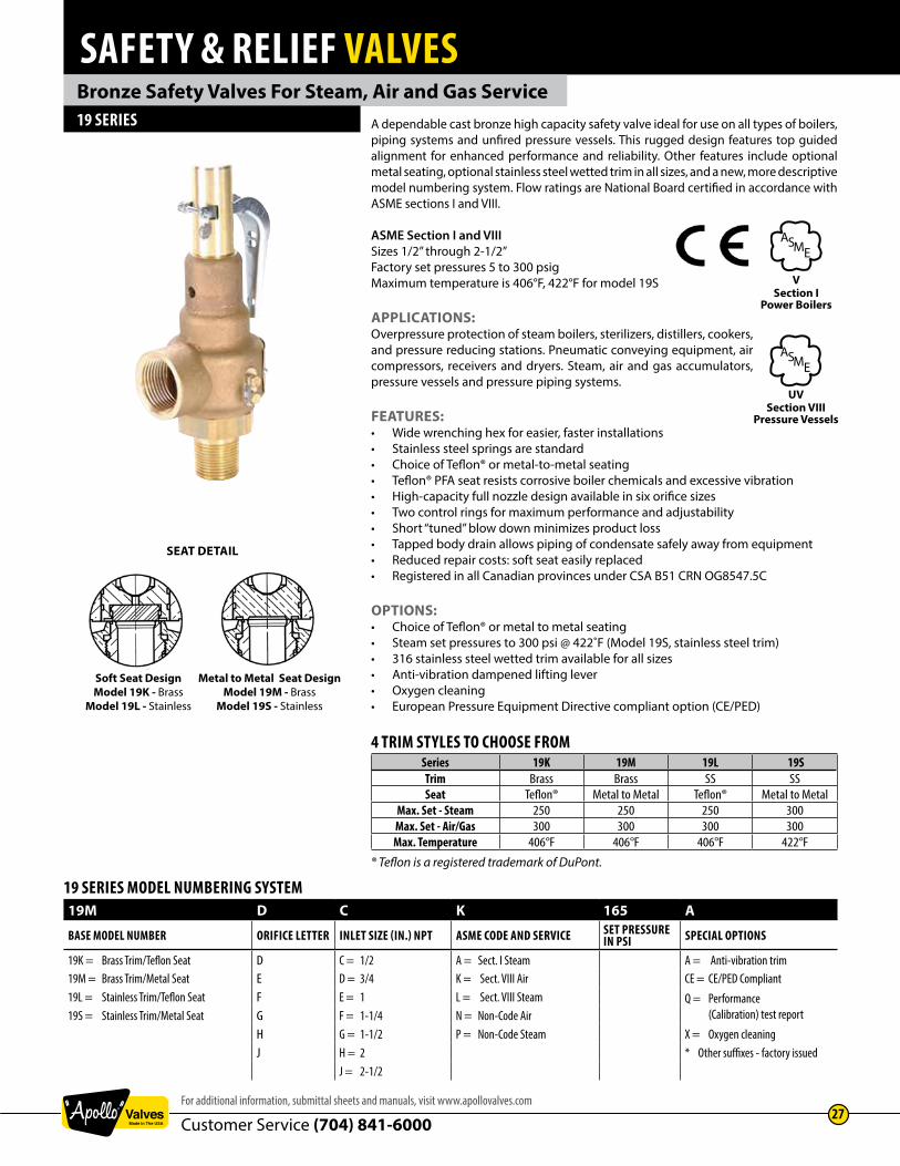
Bronze Safety Valves For Steam, Air and Gas Service19 SERIES A dependable cast bronze high capacity safety valve ideal for use on all types of boilers,
piping systems and unfired pressure vessels. This rugged design features top guided alignment for enhanced performance and reliability. Other features include optional metal seating, optional stainless steel wetted trim in all sizes, and a new, more descriptive model numbering system. Flow ratings are National Board certified in accordance with ASME sections I and VIII.
ASME Section I and VIIISizes 1/2” through 2-1/2”Factory set pressures 5 to 300 psigMaximum temperature is 406°F, 422°F for model 19S
APPLICATIONS:Overpressure protection of steam boilers, sterilizers, distillers, cookers, and pressure reducing stations. Pneumatic conveying equipment, air compressors, receivers and dryers. Steam, air and gas accumulators, pressure vessels and pressure piping systems.
FEATURES:• Wide wrenching hex for easier, faster installations• Stainless steel springs are standard • Choice of Teflon® or metal-to-metal seating• Teflon® PFA seat resists corrosive boiler chemicals and excessive vibration• High-capacity full nozzle design available in six orifice sizes • Two control rings for maximum performance and adjustability• Short “tuned” blow down minimizes product loss • Tapped body drain allows piping of condensate safely away from equipment• Reduced repair costs: soft seat easily replaced• Registered in all Canadian provinces under CSA B51 CRN OG8547.5C
OPTIONS:• Choice of Teflon® or metal to metal seating• Steam set pressures to 300 psi @ 422˚F (Model 19S, stainless steel trim)• 316 stainless steel wetted trim available for all sizes• Anti-vibration dampened lifting lever• Oxygen cleaning• European Pressure Equipment Directive compliant option (CE/PED)
4 TRIM STYLES TO CHOOSE FROMSeries 19K 19M 19L 19STrim Brass Brass SS SSSeat Teflon® Metal to Metal Teflon® Metal to Metal
Max. Set - Steam 250 250 250 300Max. Set - Air/Gas 300 300 300 300Max. Temperature 406°F 406°F 406°F 422°F
® Teflon is a registered trademark of DuPont.
SEAT DETAIL
Soft Seat DesignModel 19K - Brass
Model 19L - Stainless
Metal to Metal Seat DesignModel 19M - Brass
Model 19S - Stainless
19 SERIES MODEL NUMBERING SYSTEM19M D C K 165 A
BASE MODEL NUMBER ORIFICE LETTER INLET SIZE (IN.) NPT ASME CODE AND SERVICE SET PRESSURE IN PSI SPECIAL OPTIONS
19K = Brass Trim/Teflon Seat D C = 1/2 A = Sect. I Steam A = Anti-vibration trim19M = Brass Trim/Metal Seat E D = 3/4 K = Sect. VIII Air CE = CE/PED Compliant19L = Stainless Trim/Teflon Seat F E = 1 L = Sect. VIII Steam Q = Performance
(Calibration) test report19S = Stainless Trim/Metal Seat G F = 1-1/4 N = Non-Code AirH G = 1-1/2 P = Non-Code Steam X = Oxygen cleaningJ H = 2 * Other suffixes - factory issued
J = 2-1/2
Section IPower Boilers
ASME
V
Section VIIIPressure Vessels
ASME
UV

SAFETY & RELIEF VALVES
Customer Service (704) 841-600028
www.apollovalves.com
Bronze Safety Valves19 SERIES MATERIALS
Item Component Material19K, 19M
Material19L, 19S
1 Cap Brass Brass2 Stem Nut (2) Steel - Plated Steel - Plated3 Cap Lock Screw Brass Brass4 Lift Lever Steel - Plated Steel - Plated5 Body Bronze Bronze6 Spring Washer (2) Brass Brass7 Guide Ring Brass Brass8 Disc Brass Stainless Steel9 Guide Ring Screw Brass Brass
10 Nozzle Ring Screw Brass Brass11 Seat Insert-19K &19L PFA Teflon® PFA Teflon®12 Lift Washer Steel - Plated Steel - Plated13 Lever Pin Steel - Plated Steel - Plated14 Adjusting Screw Lock Nut Steel - Plated Steel - Plated15 Adjusting Screw Brass Brass16 Spring Stainless Steel Stainless Steel17 Stem Stainless Steel Stainless Steel18 Nozzle Ring Brass Brass19 Nozzle Brass Stainless Steel - Nameplate Stainless Steel Stainless Steel- Seal and Wire Lead/SS* Lead/SS*
* Alum/SS on CE models
DIMENSIONS AND WEIGHTSOld Model
NumberNew Model
NumberOrifice Letter
Size (in./mm)Inlet x Outlet
Dimensions (in./mm.) Wt./Ea.(lbs./kg.)A B C
19-202 19*DC D 1/2 X 3/4 2.21 6.52 1.37 1.615 x 20 56 166 35 .73
19-301 19*DD D 3/4 X 3/4 2.21 6.52 1.37 1.620 x 20 56 166 35 .73
19-302 19*ED E 3/4 X 1 2.50 7.16 1.75 2.020 x 25 64 182 44 .91
19-401 19*EE E 1 X 1 2.64 7.30 1.75 2.225 x 25 67 185 44 1.0
19-402 19*FE F 1 X 1-1/4 2.95 9.34 2.00 4.125 x 32 75 237 51 1.9
19-501 19*FF F 1-1/4 X 1-1/4 2.95 9.34 2.00 4.332 x 32 75 237 51 2.0
19-502 19*GF G 1-1/4 X 1-1/2 3.38 11.01 2.37 7.432 x 40 86 280 60 3.4
19-601 19*GG G 1-1/2 X 1-1/2 3.38 11.01 2.37 7.640 x 40 86 280 60 3.4
19-602 19*HG H 1-1/2 X 2 3.63 11.96 2.75 11.540 x 50 92 304 70 5.2
19-701 19*HH H 2 X 2 3.63 11.96 2.75 11.650 x 50 92 304 70 5.3
19*JG1 J 1-1/2F X 2-1/2 3.80 14.00 3.50 20.040 x 65 97 356 89 9.1
19-702 19*JH J 2 X 2-1/2 4.06 14.25 3.50 19.950 x 65 103 362 89 9.0
19-801 19*JJ J2-1/2 X 2-1/2 4.50 14.68 3.50 20.8
65 x 65 114 373 89 9.4
* Specify trim letter (see previous page): 1: Available in bronze trim only, Model 19KJG & 19MJG. Connections are 1-1/2” FNPT x 2-1/2” FNPT.
19 SERIES
MATERIALS19 SERIES WITH OPTION “A” ANTI-VIBRATION TRIM
Item Component Material1 Friction Clip (4) Steel Plated2 Extension Spring Stainless Steel3 Cap Lock Screw Stainless Steel
Note: Preparation includes threadlocking of all internal threaded connections.
1
3
2
C
B
A
16
17
8
1
2
13
3
5
6
11
7
9
14
18
15
4
12
10
19

SAFETY & RELIEF VALVES
Customer Service (704) 841-6000For additional information, submittal sheets and manuals, visit www.apollovalves.com
29
Bronze Safety Valves19 SERIES
US Customary Units Lbs./Hr.Orifice Letter
Area in.2D
0.129E
0.230F
0.359G
0.589H
0.919J
1.509Set Pressure psig
15 174 310 484 794 1,240 2,03520 201 359 561 920 1,435 2,35625 229 408 637 1,045 1,631 2,67730 256 457 713 1,170 1,826 2,99835 284 506 790 1,296 2,022 3,31940 311 555 866 1,421 2,217 3,64145 339 604 942 1,546 2,413 3,96250 366 653 1,019 1,672 2,608 4,28355 394 702 1,095 1,797 2,804 4,60460 421 751 1,172 1,922 2,999 4,92565 448 800 1,248 2,048 3,195 5,24670 476 849 1,326 2,175 3,394 5,57375 505 900 1,405 2,304 3,596 5,90480 533 950 1,483 2,433 3,797 6,23485 561 1,001 1,562 2,563 3,998 6,56590 590 1,051 1,641 2,692 4,200 6,89695 618 1,101 1,719 2,821 4,401 7,226
100 646 1,152 1,798 2,950 4,602 7,557105 674 1,202 1,877 3,079 4,804 7,888110 703 1,253 1,955 3,208 5,005 8,218115 731 1,303 2034 3,337 5,207 8,549120 759 1,353 2,113 3,466 5,408 8,880125 787 1,404 2,191 3,595 5,609 9,210130 816 1,454 2,270 3,724 5,811 9,541135 844 1,505 2,349 3,853 6,012 9,872140 872 1,555 2,427 3,982 6,213 10,202145 900 1,605 2,506 4,111 6,415 10,533150 929 1,656 2,585 4,240 6,616 10,864160 985 1,757 2,742 4,499 7,019 11,525170 1,042 1,857 2,899 4,757 7,422 12,186180 1,098 1,958 3,057 5,015 7,824 12,848190 1,155 2,059 3,214 5,273 8,227 13,509200 1,211 2,160 3,371 5,531 8,630 14,170210 1,268 2,261 3,529 5,789 9,033 14,832220 1,324 2,361 3,686 6,047 9,436 15,493230 1,381 2,462 3,843 6,305 9,838 16,154240 1,438 2,563 4,001 6,564 10,241 16,816250 1,494 2,664 4,158 6,822 10,644 17,477255 1,522 2,714 4,237 6,951 10,845 17,808260 1,551 2,765 4,315 7,080 11,047 18,138265 1,579 2,815 4,394 7,209 11,248 18,469270 1,607 2,865 4,473 7,338 11,449 18,800275 1,635 2,916 4,551 7,467 11,651 19,130280 1,664 2,966 4,630 7,596 11,852 19,461285 1,692 3,017 4,709 7,725 12,053 19,792290 1,720 3,067 4,787 7,854 12,255 20,122295 1,748 3,117 4,866 7,983 12,456 20,453300 1,777 3,168 4,945 8,112 12,658 20,784
Approx. 1 psiincrements 5.7 10.0 15.6 25.8 40.2 66.0
ASME SECTION I - STEAMPounds per hour (Kilograms per hour) saturated steam @ 3% overpressure. National Board Certified. Ratings are 90% of actual.
Metric Units Kg./Hr.Orifice LetterArea cm.2
D0.835
E1.483
F2.315
G3.800
H5.932
J9.733
Set Pressure barg0.34 - - - - - -0.69 - - - - - -1.1 81 145 226 371 579 9511.5 96 171 266 437 682 1,1202 114 203 317 519 811 1,331
2.5 132 235 367 602 940 1,5423 150 267 417 684 1,068 1,753
3.5 168 299 467 767 1,197 1,9644 186 331 517 849 1,326 2,175
4.5 204 364 568 932 1,454 2,3865 222 397 619 1,016 1,586 2,602
5.5 241 430 671 1,101 1,719 2,8206 259 463 723 1,186 1,851 3,037
6.5 278 496 774 1,271 1,984 3,2557 296 529 826 1,356 2,116 3,472
7.5 315 562 878 1,440 2,249 3,6908 334 595 929 1,525 2,381 3,907
8.5 352 628 981 1,610 2,514 4,1259 371 662 1,033 1,695 2,646 4,342
9.5 389 695 1,085 1,780 2,779 4,55910 408 728 1,136 1,865 2,911 4,777
10.5 426 761 1,188 1,950 3,044 4,99411 445 794 1,240 2,035 3,176 5,212
11.5 464 827 1,292 2,120 3,309 5,42912 482 860 1,343 2,204 3,441 5,647
12.5 501 893 1,395 2,289 3,574 5,86413 519 927 1,447 2,374 3,706 6,082
13.5 538 960 1,498 2,459 3,839 6,29914 556 993 1,550 2,544 3,971 6,51715 594 1,059 1,654 2,714 4,236 6,95116 631 1,125 1,757 2,884 4,501 7,38617 668 1,192 1,861 3,053 4,767 7,82118 705 1,258 1,964 3,223 5,032 8,25619 742 1,324 2,067 3,393 5,297 8,69120 779 1,390 2,171 3,563 5,562 9,126
20.7 805 1,437 2,243 3,682 5,747 9,430Approx. 0.1 barg
increments 3.7 6.6 10.3 17.0 26.5 43.5
Note: Specify model 19S with stainless steel wetted trim for steam settings beyond 250 psig / 17.2 barg.

SAFETY & RELIEF VALVES
Customer Service (704) 841-600030
www.apollovalves.com
Bronze Safety Valves19 SERIES
US Customary Units Lbs./Hr.Orifice Letter
Area in.2D
0.129E
0.230F
0.359G
0.589H
0.919J
1.509Set Pressure psig
5* 122 218 340 558 871 1,42910* 167 298 466 765 1,193 1,95815 179 320 499 820 1,279 2,10020 207 369 576 945 1,474 2,42125 234 418 652 1,070 1,670 2,74230 262 467 729 1,195 1,865 3,06335 292 521 813 1,333 2,080 3,41640 322 574 897 1,471 2,295 3,76945 352 628 981 1,609 2,510 4,12250 383 682 1,065 1,747 2,725 4,47555 413 736 1,149 1,885 2,941 4,82860 443 790 1,233 2,022 3,156 5,18165 473 844 1,317 2,160 3,371 5,53570 503 897 1,401 2,298 3,586 5,88875 534 951 1,485 2,436 3,801 6,24180 564 1,005 1,569 2,574 4,016 6,59485 594 1,059 1,653 2,712 4,231 6,94790 624 1,113 1,737 2,849 4,446 7,30095 654 1,167 1,821 2,987 4,661 7,653
100 684 1,220 1,905 3,125 4,876 8,007105 715 1,274 1,989 3,263 5,091 8,360110 745 1,328 2,073 3,401 5,306 8,713115 775 1,382 2,157 3,539 5,521 9,066120 805 1,436 2,241 3677 5,736 9,419125 835 1,489 2,325 3,814 5,951 9,772130 866 1,543 2,409 3,952 6,167 10,125135 896 1,597 2,493 4,090 6,382 10,479140 926 1,651 2,577 4,228 6,597 10,832145 956 1,705 2,661 4,366 6,812 11,185150 986 1,759 2,745 4,504 7,027 11,538155 1,017 1,812 2,829 4,641 7,242 11,891160 1,047 1,866 2,913 4,779 7,457 12,244165 1,077 1,920 2,997 4,917 7,672 12,597170 1,107 1,974 3,081 5,055 7,887 12,951180 1,167 2,082 3,249 5,331 8,317 13,657190 1,228 2,189 3,417 5,606 8,747 14,363200 1,288 2,297 3,585 5,882 9,177 15,069210 1,349 2,405 3,753 6,158 9,608 15,776220 1,409 2,512 3,921 6,433 10,038 16,482230 1,469 2,620 4,089 6,709 10,468 17,188240 1,530 2,727 4,257 6,985 10,898 17,894250 1,590 2,835 4,425 7,260 11,328 18,601255 1,620 2,889 4,509 7,398 11,543 18,954260 1,651 2,943 4,593 7,536 11,758 19,307265 1,681 2,997 4,677 7,674 11,973 19,660270 1,711 3,050 4,761 7,812 12,188 20,013275 1,741 3,104 4,845 7,950 12,403 20,366280 1,771 3,158 4,929 8,087 12,618 20,720285 1,801 3,212 5,013 8,225 12,834 21,073290 1,832 3,266 5,097 8,363 13,049 21,426295 1,862 3,320 5,181 8,501 13,264 21,779300 1,892 3,373 5,265 8,639 13,479 22,132
Approx. 1 psiincrements 6.0 10.8 16.8 27.6 43.0 70.6
ASME SECTION VIII - STEAMPounds per hour (Kilograms per hour) saturated steam at 10% overpressure. National Board Certified. Ratings are 90% of actual.
Metric Units Kg./Hr.Orifice LetterArea cm.2
D0.835
E1.483
F2.315
G3.800
H5.932
J9.733
Set Pressure barg0.34* 55 99 154 253 395 6480.69* 76 135 211 347 541 888
1.1 84 149 233 382 597 9801.5 98 175 273 448 700 1,1492 116 207 323 531 829 1,360
2.5 136 242 378 620 968 1,5893 156 277 433 711 1,110 1,821
3.5 175 313 489 802 1,251 2,0544 195 348 544 892 1,393 2,286
4.5 215 384 599 983 1,535 2,5185 235 419 654 1,074 1,676 2,750
5.5 255 454 709 1,164 1,818 2,9826 274 490 765 1,255 1,959 3,215
6.5 294 525 820 1,346 2,101 3,4477 314 561 875 1,436 2,242 3,679
7.5 334 596 930 1,527 2,384 3,9118 354 631 986 1,618 2,525 4,144
8.5 374 667 1,041 1,708 2,667 4,3769 393 702 1,096 1,799 2,808 4,608
9.5 413 737 1,151 1,890 2,950 4,84010 433 773 1,207 1,980 3,091 5,072
10.5 453 808 1,262 2,071 3,233 5,30511 473 844 1,317 2,162 3,374 5,537
11.5 493 879 1,372 2,252 3,516 5,76912 512 914 1,428 2,343 3,657 6,001
12.5 532 950 1,483 2,434 3,799 6,23413 552 985 1,538 2,524 3,941 6,466
13.5 572 1,021 1,593 2,615 4,082 6,69814 592 1,056 1,649 2,706 4,224 6,93015 631 1,127 1,759 2,887 4,507 7,39516 671 1,197 1,870 3,068 4,790 7,85917 711 1,268 1,980 3,250 5,073 8,32418 750 1,339 2,091 3,431 5,356 8,78819 790 1,410 2,201 3,612 5,639 9,25320 830 1,480 2,312 3,794 5,922 9,717
20.7 857 1,530 2,389 3,920 6,120 10,042Approx. 0.1 barg
increments 4.0 7.1 11.5 18.1 28.3 46.4
Note: Specify model 19S with stainless steel wetted trim for steam settings beyond 250 psig / 17.2 barg.
* Settings below 15 psi (1.1 barg) are non-ASME code.

SAFETY & RELIEF VALVES
Customer Service (704) 841-6000For additional information, submittal sheets and manuals, visit www.apollovalves.com
31
Bronze Safety Valves19 SERIES
US Customary Units SCFMOrifice Letter
Area in.2D
0.129E
0.230F
0.359G
0.589H
0.919J
1.509Set Pressure psig
5* 39 69 108 178 277 45510* 54 97 151 248 387 63515 64 114 178 292 455 74720 74 131 205 336 525 86225 83 149 232 381 594 97630 93 166 259 426 664 1,09035 104 185 289 475 740 1,21640 115 204 319 524 817 1,34245 125 224 349 573 894 1,46750 136 243 379 622 970 1,59355 147 262 409 671 1,047 1,71960 158 281 439 720 1,123 1,84465 168 300 469 769 1,200 1,97070 179 319 499 818 1,276 2,09675 190 339 528 867 1,353 2,22180 201 358 558 916 1,429 2,34785 211 377 588 965 1,506 2,47390 222 396 618 1,014 1,583 2,59895 233 415 648 1,063 1,659 2,724
100 244 434 678 1,112 1,736 2,850105 254 454 708 1,161 1,812 2,976110 265 473 738 1,211 1,889 3,101115 276 492 768 1,260 1,965 3,227120 287 511 798 1,309 2,042 3,353125 297 530 828 1,358 2,118 3,478130 308 549 857 1,407 2,195 3,604135 319 568 887 1,456 2,271 3,730140 330 588 917 1,505 2,348 3,855145 340 607 947 1,554 2,425 3,981150 351 626 977 1,603 2,501 4,107160 373 664 1,037 1,701 2,654 4,358165 383 683 1,067 1,750 2,731 4,484170 394 703 1,097 1,799 2,807 4,610180 416 741 1,156 1,897 2,960 4,861190 437 779 1,216 1,996 3,114 5,112200 459 818 1,276 2,094 3,267 5,364210 480 856 1,336 2,192 3,420 5,615220 502 894 1,396 2,290 3,573 5,867230 523 932 1,456 2,388 3,726 6,118240 545 971 1,515 2,486 3,879 6,369250 566 1,009 1,575 2,584 4,032 6,621255 577 1,028 1,605 2,633 4,109 6,746260 587 1,047 1,635 2,682 4,185 6,872265 598 1,067 1,665 2,731 4,262 6,998270 609 1,086 1,695 2,781 4,338 7,124275 620 1,105 1,725 2,830 4,415 7,249280 630 1,124 1,755 2,879 4,491 7,375285 641 1,143 1,784 2,928 4,568 7,501290 652 1,162 1,814 2,977 4,645 7,626295 663 1,182 1,844 3,026 4,721 7,752300 673 1,201 1,874 3,075 4,798 7,878
Approx. 1 psiincrements 2.1 3.8 6.0 9.8 15.3 25.1
ASME SECTION VIII - AIRStandard cubic feet per minute (Normalized cubic meters per hour) of air at 10% overpressure. National Board Certified. Ratings are 90% of actual.
Metric Units Nm3/Hr.Orifice LetterArea cm.2
D0.835
E1.483
F2.315
G3.800
H5.932
J9.733
Set Pressure barg0.34* 66 118 184 302 471 7730.69* 92 164 256 421 657 1,078
1.1 112 199 311 510 796 1,3061.5 131 233 364 598 933 1,5312 155 276 431 708 1,105 1,813
2.5 181 323 504 827 1,291 2,1193 207 370 578 948 1,480 2,428
3.5 234 417 651 1,069 1,669 2,7384 260 464 725 1,190 1,857 3,047
4.5 287 511 799 1,311 2,046 3,3575 313 559 872 1,431 2,235 3,667
5.5 340 606 946 1,552 2,423 3,9766 366 653 1,020 1,673 2,612 4,286
6.5 392 700 1,093 1,794 2,801 4,5967 419 747 1,167 1,915 2,989 4,905
7.5 445 795 1,241 2,036 3,178 5,2158 472 842 1,314 2,157 3,367 5,524
8.5 498 889 1,388 2,278 3,555 5,8349 525 936 1,461 2,398 3,744 6,144
9.5 551 983 1,535 2,519 3,933 6,45310 577 1,030 1,609 2,640 4,122 6,763
10.5 604 1,078 1,682 2,761 4,310 7,07211 630 1,125 1,756 2,882 4,499 7,382
11.5 657 1,172 1,830 3,003 4,688 7,69212 683 1,219 1,903 3,124 4,876 8,001
12.5 710 1,266 1,977 3,245 5,065 8,31113 736 1,313 2,051 3,365 5,254 8,621
13.5 763 1,361 2,124 3,486 5,442 8,93014 789 1,408 2,198 3,607 5,631 9,24015 842 1,502 2,345 3,849 6,008 9,85916 895 1,596 2,493 4,091 6,386 10,47817 948 1,691 2,640 4,332 6,763 11,09718 1,000 1,785 2,787 4,574 7,141 11,71719 1,053 1,879 2,935 4,816 7,518 12,33620 1,106 1,974 3,082 5,058 7,895 12,955
20.7 1,143 2,040 3,185 5,227 8,160 13,389Approx. 0.1 barg
increments 5.3 9.4 14.7 24.2 37.7 61.9
Note: To correct for temperature or specific gravities other than air (=1.0), multiply the SCFM from the capacity tables by factor Ksg (See page 50)
* Settings below 15 psi (1.1 barg) are non-ASME code.

SAFETY & RELIEF VALVES
Customer Service (704) 841-600032
www.apollovalves.com
1
2
3
4
5
6
20
7
8
9
10
11
12
21
22
19
18
17
16
15
14
13
OEM Style Bronze Safety Valves for Steam, Air and Non-Hazardous Gas29 SERIES Conbraco 29 Series is ideally suited for OEM applications where compact size,
dependable performance and maximum economy are required. These rugged safety valves feature a top guided design and patented Teflon® “soft-seat” for dramatically reduced seat leakage. Flow ratings are National Board certified.
ASME Sections I and VIIISizes 3/8” - 1-1/4” NPTFactory set pressures 30 to 200 psigMaximum temperature 406˚F
APPLICATIONS:Small to medium sized steam power boilers, sterilizers and distillers, air compressors and receivers, pressure vessels and pressure piping systems.
FEATURES:• Stainless steel springs are standard • PFA Teflon® seat resists corrosive boiler chemicals• Rust-proofed steel stem and spring washers • Lower control ring ensures short, consistent blowdown• Tapped body drain allows piping of condensate away from equipment• Reduced repair costs; soft seat easily replaced• Registered in all Canadian Provinces under CSA B51 CRN OG8547.5C
OPTIONS:• 316 Stainless steel wetted trim (29-202 & 29-303 sizes only)• Oxygen cleaning• European pressure equipment directive compliant option (CE/PED)
MATERIALSItem Component Material
1 Cap Bronze or Brass2 Stem Steel - Plated3 Lift Washer Steel - Plated4 Lift Lever Steel - Plated5 Adjusting Screw Brass6 Lock Nut Brass7 Body Bronze8 Nameplate Stainless Steel9 Drive Screws Stainless Steel
10 Set Screw Brass11 Blowdown Ring Brass12 Nozzle* Brass/Stainless13 Seat Insert Teflon® PFA14 Disc Holder Brass15 Lower Washer Steel - Plated16 Seat Retainer* Brass/Stainless17 Stem Pin Stainless Steel18 Spring Stainless Steel19 Upper Washer Steel - Plated20 Lock Screw Steel - Plated21 Lever Pin Steel - Plated22 Retaining Ring Stainless Steel- Seal & Wire Lead/Steel
®Teflon is a registered trademark of DuPont. * Optional stainless steel wetted trim for models 29-202XXL and 29-302XXL. Items 12 & 16 are type 316 stainless steel.
Section IPower Boilers
ASME
VSection VIII
Pressure Vessels
ASME
UV
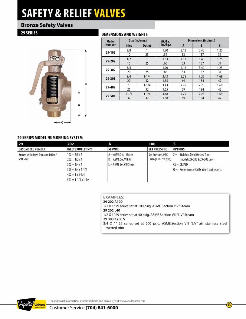
SAFETY & RELIEF VALVES
Customer Service (704) 841-6000For additional information, submittal sheets and manuals, visit www.apollovalves.com
33
Bronze Safety Valves29 SERIES DIMENSIONS AND WEIGHTS
ModelNumber
Size (in./mm.) Wt./Ea.(lbs./kg.)
Dimensions (in./mm.)Inlet Outlet A B C
29-102 3/8 1 1.30 2.12 5.40 1.2510 25 .59 53 137 31
29-202 1/2 1 1.33 2.12 5.40 1.2515 25 .60 53 137 31
29-302 3/4 1 1.90 2.12 5.40 1.2520 25 .86 53 137 31
29-303 3/4 1-1/4 3.43 2.75 7.25 1.6920 32 1.55 69 184 42
29-402 1 1-1/4 3.43 2.75 7.25 1.6925 32 1.55 69 184 42
29-501 1-1/4 1-1/4 3.48 2.75 7.25 1.69 32 32 1.58 69 184 42
EXAMPLES:29 202 A1001/2 X 1” 29 series set at 100 psig, ASME Section I “V” Steam29 202 L401/2 X 1” 29 series set at 40 psig, ASME Section VIII “UV” Steam29 303 K200 S3/4 X 1” 29 series set at 200 psig, ASME Section VIII “UV” air, stainless steel wetted trim
29 SERIES MODEL NUMBERING SYSTEM29 202 A 100 SBASE MODEL NUMBER INLET x OUTLET NPT SERVICE SET PRESSURE OPTIONS
Bronze with Brass Trim and Teflon® Soft Seat
102 = 3/8 x 1 A = ASME Sec I Steam Set Pressure, PSIG (range 30-200 psig)
S = Stainless Steel Wetted Trim (models 29-202 & 29-303 only)202 = 1/2 x 1 K = ASME Sec VIII Air
302 = 3/4 x 1 L = ASME Sec VIII Steam CE = CE/PED303 = 3/4 x 1-1/4 Q = Performance (Calibration) test reports402 = 1 x 1-1/4501 = 1-1/4 x 1-1/4
B
A
C

SAFETY & RELIEF VALVES
Customer Service (704) 841-600034
www.apollovalves.com
Bronze Safety Valves29 SERIES
US Customary Units Lbs./Hr.Model No.
Seat Dia. (in.)29-102, 29-202, 29-302
0.50029-303, 29-402, 29-501
0.737Set Pressure psig
30 164 33035 182 36740 201 40545 220 44250 238 47955 257 51760 275 55465 294 59170 312 62875 331 66480 349 70285 368 73990 386 77795 405 814
100 423 851105 442 888110 460 925115 479 963120 497 1,000125 516 1,036130 534 1,074135 553 1,112140 571 1,149145 590 1,186150 608 1,223155 627 1,261160 645 1,298165 664 1,335170 683 1,372175 701 1,409180 720 1,447185 738 1,484190 757 1,521195 775 1,558200 794 1,596
Approx. 1 psiincrements 3.7 7.4
ASME SECTION I - STEAMPounds per hour (Kilograms per hour) saturated steam at 3% overpressure. National Board Certified. Ratings are 90% of actual.
Metric Units Kg./Hr.Model No.
Seat Dia. (mm.)29-102, 29-202, 29-302
12.7029-303, 29-402, 29-501
18.72Set Pressure barg
2.1 77 1552.5 86 1743 98 197
3.5 110 2214 122 245
4.5 134 2695 146 293
5.5 158 3186 170 342
6.5 182 3677 195 391
7.5 207 4168 219 440
8.5 231 4659 243 489
9.5 255 51410 268 538
10.5 280 56311 292 587
11.5 304 61212 316 636
12.5 329 66113 341 685
13.5 353 71013.8 360 724
Approx. 0.1 bargincrements 2.44 4.9

SAFETY & RELIEF VALVES
Customer Service (704) 841-6000For additional information, submittal sheets and manuals, visit www.apollovalves.com
35
Bronze Safety Valves29 SERIES
US Customary Units Lbs./Hr.Model No.
Seat Dia. (in.)29-102, 29-202, 29-302
0.50029-303, 29-402, 29-501
0.737Set Pressure psig
30 172 34535 191 38540 211 42545 231 46550 251 50455 270 54460 290 58465 310 62470 330 66475 350 70480 369 74485 389 78390 409 82395 429 863
100 448 902105 468 943110 488 982115 508 1,022120 528 1,062125 547 1,102130 567 1,142135 587 1,182140 607 1,221145 626 1,261150 646 1,299155 666 1,341160 686 1,381165 706 1,420170 725 1,460175 745 1,500180 765 1,540185 785 1,580190 804 1,620195 824 1,659200 844 1,697
Approx. 1 psiincrements 3.95 8.0
ASME SECTION VIII STEAMPounds per hour (Kilograms per hour) saturated steam at 10% overpressure. National Board Certified. Ratings are 90% of actual.
Metric Units Kg./Hr.Model No.
Seat Dia. (mm.)29-102, 29-202, 29-302
12.7029-303, 29-402, 29-501
18.72Set Pressure barg
2.1 79 1582.5 89 1793 102 205
3.5 115 2314 128 257
4.5 141 2845 154 310
5.5 167 3366 180 362
6.5 193 3887 206 414
7.5 219 4418 232 467
8.5 245 4939 258 519
9.5 271 54510 284 571
10.5 297 59811 310 624
11.5 323 65012 336 676
12.5 349 70213 362 728
13.5 375 75513.8 383 770
Approx. 0.1 bargincrements 2.6 5.22

SAFETY & RELIEF VALVES
Customer Service (704) 841-600036
www.apollovalves.com
Bronze Safety Valves29 SERIES
US Customary Units SCFMModel No.
Seat Dia. (in.)29-102, 29-202, 29-302
0.50029-303, 29-402, 29-501
0.737Set Pressure psig
30 61 12335 68 13740 75 15145 82 16550 89 18055 96 19360 103 20865 110 22270 117 23675 124 25080 131 26485 138 27890 145 29295 152 307
100 159 321105 166 335110 173 349115 180 363120 187 378125 194 392130 201 406135 208 420140 215 434145 222 448150 229 463155 236 477160 243 491165 250 505170 257 519175 265 533180 272 547185 279 562190 286 576195 293 590200 300 604
Approx. 1 psiincrements 1.4 2.8
ASME SECTION VIII AIRStandard cubic feet per minute (Normalized cubic meters per hour) of air at 10% overpressure. National Board Certified. Ratings are 90% of actual.
Metric Units Nm3./Hr.Model No.
Seat Dia. (mm.)29-102, 29-202, 29-302
12.7029-303, 29-402, 29-501
18.72Set Pressure barg
2.1 105 2102.5 118 2383 136 273
3.5 153 3084 170 342
4.5 188 3775 205 412
5.5 222 4476 240 482
6.5 257 5167 274 551
7.5 291 5868 309 621
8.5 326 6559 343 690
9.5 361 72510 378 760
10.5 395 79511 413 829
11.5 430 86412 447 899
12.5 464 93413 482 969
13.5 499 1,00313.8 509 1,024
Approx. 0.1 bargincrements 3.46 6.96
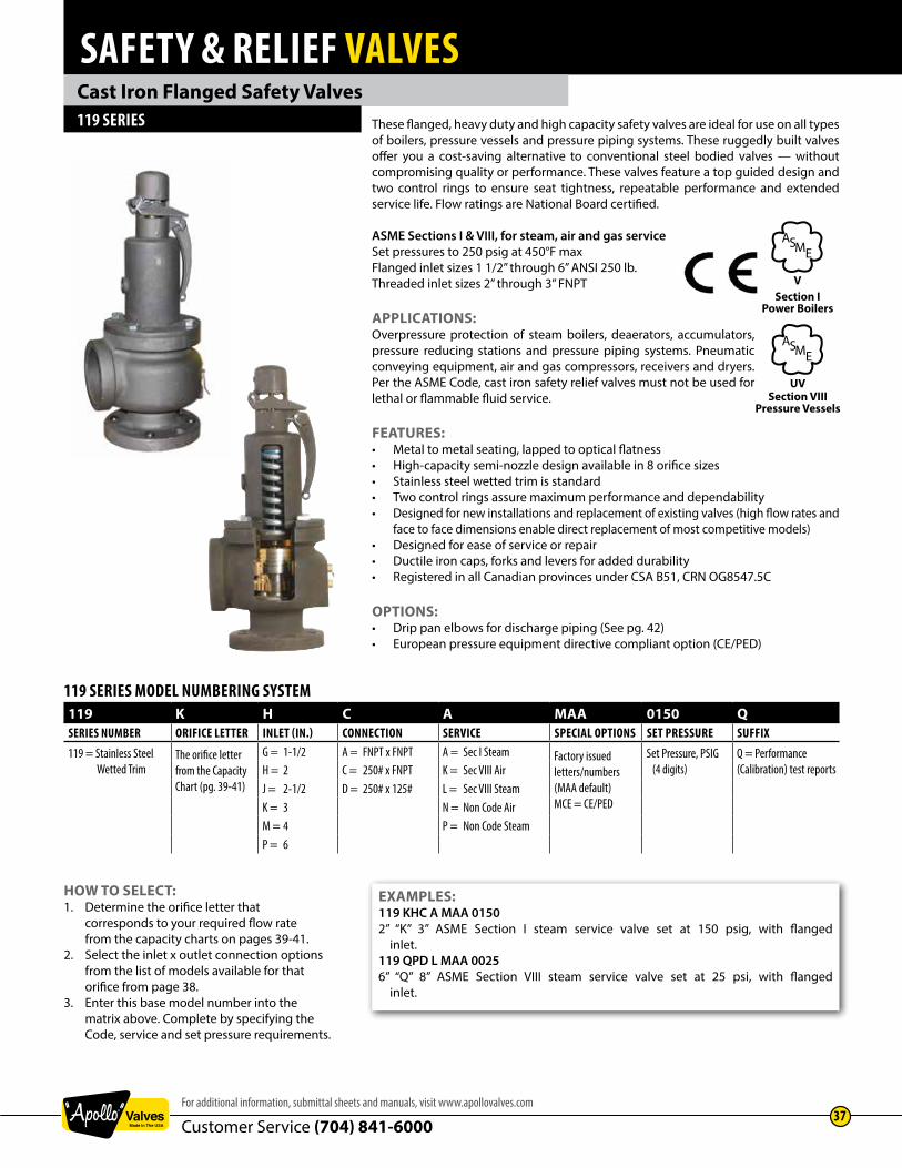
SAFETY & RELIEF VALVES
Customer Service (704) 841-6000For additional information, submittal sheets and manuals, visit www.apollovalves.com
37
Cast Iron Flanged Safety Valves119 SERIES These flanged, heavy duty and high capacity safety valves are ideal for use on all types
of boilers, pressure vessels and pressure piping systems. These ruggedly built valves offer you a cost-saving alternative to conventional steel bodied valves — without compromising quality or performance. These valves feature a top guided design and two control rings to ensure seat tightness, repeatable performance and extended service life. Flow ratings are National Board certified.
ASME Sections I & VIII, for steam, air and gas service Set pressures to 250 psig at 450°F maxFlanged inlet sizes 1 1/2” through 6” ANSI 250 lb. Threaded inlet sizes 2” through 3” FNPT
APPLICATIONS:Overpressure protection of steam boilers, deaerators, accumulators, pressure reducing stations and pressure piping systems. Pneumatic conveying equipment, air and gas compressors, receivers and dryers. Per the ASME Code, cast iron safety relief valves must not be used for lethal or flammable fluid service.
FEATURES:• Metal to metal seating, lapped to optical flatness• High-capacity semi-nozzle design available in 8 orifice sizes• Stainless steel wetted trim is standard• Two control rings assure maximum performance and dependability• Designed for new installations and replacement of existing valves (high flow rates and face to face dimensions enable direct replacement of most competitive models) • Designed for ease of service or repair• Ductile iron caps, forks and levers for added durability• Registered in all Canadian provinces under CSA B51, CRN OG8547.5C
OPTIONS:• Drip pan elbows for discharge piping (See pg. 42)• European pressure equipment directive compliant option (CE/PED)
HOW TO SELECT:1. Determine the orifice letter that corresponds to your required flow rate from the capacity charts on pages 39-41.2. Select the inlet x outlet connection options from the list of models available for that orifice from page 38.3. Enter this base model number into the matrix above. Complete by specifying the Code, service and set pressure requirements.
EXAMPLES:119 KHC A MAA 0150 2” “K” 3” ASME Section I steam service valve set at 150 psig, with flanged inlet.119 QPD L MAA 0025 6” “Q” 8” ASME Section VIII steam service valve set at 25 psi, with flanged inlet.
119 SERIES MODEL NUMBERING SYSTEM119 K H C A MAA 0150 QSERIES NUMBER ORIFICE LETTER INLET (IN.) CONNECTION SERVICE SPECIAL OPTIONS SET PRESSURE SUFFIX
119 = Stainless Steel Wetted Trim
The orifice letter from the CapacityChart (pg. 39-41)
G = 1-1/2 A = FNPT x FNPT A = Sec I Steam Factory issued letters/numbers(MAA default)MCE = CE/PED
Set Pressure, PSIG (4 digits)
Q = Performance (Calibration) test reportsH = 2 C = 250# x FNPT K = Sec VIII Air
J = 2-1/2 D = 250# x 125# L = Sec VIII SteamK = 3 N = Non Code AirM = 4 P = Non Code SteamP = 6
Section IPower Boilers
ASME
V
Section VIIIPressure Vessels
ASME
UV

SAFETY & RELIEF VALVES
Customer Service (704) 841-600038
www.apollovalves.com
Cast Iron Flanged Safety Valves119 SERIES
MATERIALSItem Component Material
1 Body Gray Iron 2 Nozzle Stainless Steel3 Nozzle Ring Screw Brass4 Guide Ring Screw Brass5 Disc Stainless Steel6 Bonnet Bolt Steel (Plated) 7 Stem Steel (Plated) 8 Spring Washer Steel (Plated) 9 Test Lever Ductile Iron or
10 Clevis Pin Steel (Plated) 11 Lifting Fork Ductile Iron 12 Stem Nut Steel (Plated) 13 Stem Nut Lock Nut Steel (Plated) 14 Lifting Cap Ductile Iron 15 Clevis Pin Steel (Plated) 16 Adjusting Screw Brass 17 Lock Nut Steel (Plated) 18 Lift Cap Lockscrew Steel (Plated) 19 Bonnet Gray Iron 20 Spring Steel (Plated) or SS21 Disc Guide Brass or Bronze 22 Nozzle Ring Brass or Bronze- Nameplate Aluminum - Seal and Wire Lead/Steel- Seal and Wire (CE) Alum/SS
DIMENSIONS AND WEIGHTSModel
NumberSize (in./mm.)Inlet x Outlet
OrificeSize
Dimensions (in./mm.) Hex Flat D(in./mm)
Weight(lbs./kg.)A B C
119 JGC 1-1/2 250# X 2-1/2 FNPT J 15 4 4.31 35DN40 x DN65 381 101 109 15.8
119 KHC 2 250# X 3 FNPT K 16 4 4.63 36DN50 x DN80 406 101 109 16.3
119 KHA 2 FNPT X 3 FNPT K 16 4 4.63 3.75 37DN50 x DN80 406 101 109 95 16.7
119 KJC 2-1/2 250# X 3 FNPT K 16 4 4.63 41DN65 x DN80 406 101 109 18.6
119 KKC 3 250# X 3 FNPT K 16 4 4.63 45DN80 x DN80 406 101 109 20.5
119 LJC 2-1/2 250# X 4 FNPT L 22 5.13 5.63 84DN65 x DN100 558 130 143 38.1
119 LJA 2-1/2 FNPT X 4 FNPT L 22 5.13 5.63 5.38 81DN65 x DN100 558 130 143 136 36.7
119 LKC 3 250# X 4 FNPT L 22 5.13 5.63 85DN80 x DN100 558 130 143 38.5
119 LMC 4 250# X 4 FNPT L 22 5.13 5.63 90DN100 x DN100 558 130 143 40.9
119 MKA 3 FNPT X 4 FNPT M 22 5.13 5.63 5.38 80DN80 x DN100 558 130 143 136 36.2
119 MKC 3 250# X 4 FNPT M 22 5.13 5.63 87DN80 x DN100 558 130 143 39.4
119 MMC 4 250# X 4 FNPT M 22 5.13 5.63 95DN100 x DN100 558 130 143 43.2
119 NMD 4 250# X 6 125# N 28 7.25 6.75 210DN100 x DN150 711 184 171 95.2
119 PMD 4 250# X 6 125# P 28 7.25 6.75 215DN100 x DN150 711 184 171 97.5
119 QPD 6 250# X 8 125# Q 42 10 9.25 530DN150 x DN200 1066 254 234 240.4
119 RPD 6 250# X 8 125# R 42 10 9.25 530DN150 x DN200 1066 254 234 240.4
13
12
11
10
9
8
7
6
5
4
3
2
1
14
16
17
18
19
22
20
21
A
C
D
15
B

SAFETY & RELIEF VALVES
Customer Service (704) 841-6000For additional information, submittal sheets and manuals, visit www.apollovalves.com
39
Cast Iron Flanged Safety Valves119 SERIES ASME SECTION I STEAM
Pounds per hour (Kilograms per hour) saturated steam at 3% overpressure. National Board Certified. Ratings are 90% of actual.
US Customary Units Lbs./Hr.Orifice Letter
Area in.2J
1.358K
1.926L
2.99M
3.774N
4.55P
6.692Q
11.593R
16.786Set Pressure psig
15 1,947 2,761 4,286 5,410 6,522 9,592 16,617 24,06120 2,254 3,196 4,962 6,263 7,551 11,105 19,238 27,85625 2,561 3,632 5,638 7,116 8,579 12,618 21,859 31,65130 2,868 4,067 6,314 7,969 9,608 14,131 24,480 35,44635 3,175 4,502 6,990 8,823 10,637 15,644 27,101 39,24140 3,482 4,938 7,666 9,676 11,665 17,157 29,722 43,03645 3,789 5,373 8,342 10,529 12,694 18,670 32,343 46,83150 4,096 5,809 9,018 11,382 13,723 20,183 34,964 50,62655 4,403 6,244 9,694 12,236 14,751 21,696 37,585 54,42160 4,710 6,680 10,370 13,089 15,780 23,209 40,206 58,21665 5,017 7,115 11,046 13,942 16,809 24,722 42,827 62,01170 5,330 7,559 11,735 14,812 17,858 26,265 45,501 65,88275 5,646 8,008 12,432 15,691 18,918 27,823 48,200 69,79180 5,962 8,456 13,128 16,570 19,977 29,382 50,900 73,70085 6,279 8,905 13,824 17,449 21,037 30,940 53,600 77,60990 6,595 9,353 14,520 18,328 22,096 32,498 56,299 81,51895 6,911 9,802 15,217 19,207 23,156 34,057 58,999 85,427
100 7,227 10,250 15,913 20,085 24,215 35,615 61,698 89,336105 7,544 10,699 16,609 20,964 25,275 37,173 64,398 93,245110 7,860 11,147 17,305 21,843 26,334 38,732 67,098 97,154115 8,176 11,596 18,002 22,722 27,394 40,290 69,797 101,063120 8,492 12,044 18,698 23,601 28,453 41,848 72,497 104,971125 8,809 12,493 19,394 24,480 29,513 43,407 75,197 108,880130 9,125 12,941 20,091 25,358 30,573 44,965 77,896 112,789135 9,441 13,390 20,787 26,237 31,632 46,524 80,596 116,698140 9,757 13,838 21,483 27,116 32,692 48,082 83,295 120,607145 10,073 14,287 22,179 27,995 33,751 49,640 85,995 124,516150 10,390 14,735 22,876 28,874 34,811 51,199 88,695 128,425155 10,706 15,184 23,572 29,753 35,870 52,757 91,394 132,334160 11,022 15,632 24,268 30,631 36,930 54,315 94,094 136,243165 11,338 16,081 24,964 31,510 37,989 55,874 96,794 140,152170 11,655 16,529 25,661 32,389 39,049 57,432 99,493 144,061175 11,971 16,978 26,357 33,268 40,108 58,990 102,193 147,969180 12,287 17,426 27,053 34,147 41,168 60,549 104,893 151,878185 12,603 17,875 27,750 35,026 42,228 62,107 107,592 155,787190 12,920 18323 28,446 35,905 43,287 63,665 110,292 159,696195 13,236 18772 29,142 36,783 44,347 65,224 112,991 163,605200 13,552 19220 29,838 37,662 45,406 66,782 115,691 167,514205 13,868 19669 30,535 38,541 46,466 68,340 118,391 171,423210 14,184 20117 31,231 39,420 47,525 69,899 121,090 175,332215 14,501 20566 31,927 40,299 48,585 71,457 123,790 179,241220 14,817 21014 32,623 41,178 49,644 73,015 126,490 183,150225 15,133 21463 33,320 42,056 50,704 74,574 129,189 187,059230 15,449 21911 34,016 42,935 51,764 76,132 131,889 190,958235 15,766 22360 34,712 43,814 52,823 77,691 134,589 194,876240 16,082 22808 35,409 44,693 53,883 79,249 137,288 198,785245 16,398 23257 36,105 45,572 54,942 80,807 139,988 202,694250 16,714 23705 36,801 46,451 56,002 82,366 142,687 206,603
Approx. 1 psi Increments 63 90 139 176 212 312 540 782
Metric Units Kg./Hr.Orifice LetterArea cm.2
J8.762
K12.426
L19.287
M24.347
N29.357
P43.174
Q74.795
R108.294
Set Pressure barg1.1 910 1,290 2,002 2,527 3,048 4,482 7,764 11,2421.5 1,071 1,519 2,358 2,976 3,589 5,278 9,144 13,2392 1,273 1,806 2,803 3,538 4,266 6,274 10,868 15,736
2.5 1,475 2,092 3,247 4,099 4,943 7,269 12,593 18,2333 1,677 2,379 3,692 4,660 5,619 8,264 14,317 20,729
3.5 1,879 2,665 4,137 5,222 6,296 9,260 16,041 23,2264 2,081 2,952 4,581 5,783 6,973 10,255 17,766 25,723
4.5 2,283 3,238 5,026 6,344 7,650 11,250 19,490 28,2195 2,490 3,531 5,481 6,919 8,343 12,270 21,256 30,776
5.5 2,698 3,827 5,939 7,497 9,040 13,295 23,032 33,3486 2,906 4,122 6,397 8,075 9,737 14,320 24,808 35,919
6.5 3,114 4,417 6,855 8,653 10,434 15,345 26,584 38,4917 3,322 4,712 7,313 9,232 11,131 16,371 28,360 41,062
7.5 3,530 5,007 7,771 9,810 11,828 17,396 30,136 43,6348 3,738 5,302 8,229 10,388 12,526 18,421 31,912 46,205
8.5 3,947 5,597 8,687 10,966 13,223 19,446 33,689 48,7779 4,155 5,892 9,145 11,544 13,920 20,471 35,465 51,349
9.5 4,363 6,187 9,603 12,122 14,617 21,497 37,241 53,92010 4,571 6,482 10,061 12,700 15,314 22,522 39,017 56,492
10.5 4,779 6,777 10,519 13,279 16,011 23,547 40,793 59,06311 4,987 7,072 10,977 13,857 16,708 24,572 42,569 61,635
11.5 5,195 7,367 11,435 14,435 17,405 25,598 44,345 64,20612 5,403 7,662 11,893 15,013 18,102 26,623 46,121 66,778
12.5 5,611 7,958 12,351 15,591 18,800 27,648 47,897 69,34913 5,819 8,253 12,809 16,169 19,497 28,673 49,673 71,921
13.5 6,027 8,548 13,267 16,747 20,194 29,698 51,449 74,49214 6,235 8,843 13,725 17,325 20,891 30,724 53,225 77,06415 6,651 9,433 14,641 18,482 22,285 32,774 56,777 82,20716 7,068 10,023 15,557 19,638 23,679 34,824 60,330 87,35017 7,484 10,613 16,473 20,794 25,073 36,875 63,882 92,493
Approx 0.1 bargIncrements 41.6 59.0 91.6 115.6 139.4 205.0 355.2 514.3

SAFETY & RELIEF VALVES
Customer Service (704) 841-600040
www.apollovalves.com
Cast Iron Flanged Safety Valves119 SERIES ASME SECTION VIII STEAM
Pounds per hour (Kilograms per hour) saturated steam at 10% overpressure. National Board Certified. Ratings are 90% of actual.
US Customary Units Lbs./Hr.Orifice Letter
Area in.2J
1.358K
1.926L
2.99M
3.774N
4.55P
6.692Q
11.593R
16.786Set Pressure psig
5* 1,312 1,860 2,888 3,645 4,395 6,464 11,198 16,21310* 1,798 2,550 3,957 4,995 6,023 8,859 15,346 22,22015 2,008 2,848 4,421 5,580 6,728 9,895 17,141 24,82020 2,315 3,283 5,097 6,433 7,756 11,408 19,762 28,61525 2,622 3,719 5,773 7,287 8,785 12,921 22,383 32,41030 2,929 4,154 6,449 8,140 9,814 14,434 25,004 36,20535 3,267 4,633 7,193 9,079 10,945 16,098 27,887 40,37940 3,604 5,112 7,936 10,017 12,077 17,762 30,771 44,55445 3,942 5,591 8,680 10,956 13,208 19,426 33,654 48,72950 4,280 6,070 9,423 11,894 14,340 21,091 36,537 52,90355 4,618 6,549 10,167 12,833 15,471 22,755 39,420 57,07860 4,955 7,028 10,911 13,771 16,603 24,419 42,303 61,25265 5,293 7,507 11,654 14,710 17,735 26,083 45,186 65,42770 5,631 7,986 12,398 15,649 18,866 27,748 48,069 69,60175 5,969 8,465 13,141 16,587 19,998 29,412 50,952 73,77680 6,306 8,944 13,885 17,526 21,129 31,076 53,835 77,95185 6,644 9,423 14,629 18,464 22,261 32,740 56,719 82,12590 6,982 9,902 15,372 19,403 23,392 34,405 59,602 86,30095 7,319 10,381 16,116 20,341 24,524 36,069 62,485 90,474
100 7,657 10,860 16,859 21,280 25,655 37,733 65,368 94,649105 7,995 11,339 17,603 22,218 26,787 39,397 68,251 98,823110 8,333 11,818 18,346 23,157 27,919 41,062 71,134 102,998115 8,670 12,297 19,090 24,096 29,050 42,726 74,017 107,173120 9,008 12,776 19,834 25,034 30,182 44,390 76,900 111,347125 9,346 13,255 20,577 25,973 31,313 46,055 79,783 115,522130 9,684 13,734 21,321 26,911 32,445 47,719 82,666 119,696135 10,021 14,213 22,064 27,850 33,576 49,383 85,550 123,871140 10,359 14,692 22,808 28,788 34,708 51,047 88,433 128,045145 10,697 15,171 23,552 29,727 35,839 52,712 91,316 132,220150 11,034 15,650 24,295 30,666 36,971 54,376 94,199 136,395155 11,372 16,129 25,039 31,604 38,103 56,040 97,082 140,569160 11,710 16,608 25,782 32,543 39,234 57,704 99,965 144,744165 12,048 17,087 26,526 33,481 40,366 59,369 102,848 148,918170 12,385 17,566 27,270 34,420 41,497 61,033 105,731 153,093175 12,723 18,045 28,013 35,358 42,629 62,697 108,614 157,267180 13,061 18,524 28,757 36,297 43,760 64,361 111,497 161,442185 13,399 19,003 29,500 37,236 44,892 66,026 114,381 165,617190 13,736 19,482 30,244 38,174 46,023 67,690 117,264 169,791195 14,074 19,961 30,988 39,113 47,155 69,354 120,147 173,966200 14,412 20,440 31,731 40,051 48,287 71,018 123,030 178,140205 14,749 20,919 32,475 40,990 49,418 72,683 125,913 182,315210 15,087 21,398 33,218 41,928 50,550 74,347 128,796 186,489215 15,425 21,876 33,962 42,867 51,681 76,011 131,679 190,664220 15,763 22,355 34,706 43,806 52,813 77,675 134,562 194,839225 16,100 22,834 35,449 44,744 53,944 79,340 137,445 199,013230 16,438 23,313 36,193 45,683 55,076 81,004 140,329 203,188235 16,776 23,792 36,936 46,621 56,207 82,668 143,212 207,362240 17,113 24,271 37,680 47,560 57,339 84,332 146,095 211,537245 17,451 24,750 38,424 48,498 58,471 85,997 148,978 215,711250 17,789 25,229 39,167 49,437 59,602 87,661 151,861 219,886
Approx. 1 psiIncrement 68 96 149 188 226 333 577 835
*Settings below 15 psi (1.1 barg) are non-ASME code.
Metric Units Kg./Hr.Orifice LetterArea cm.2
J8.762
K12.426
L19.287
M24.347
N29.357
P43.174
Q74.795
R108.294
Set Pressure barg.34* 590 836 1,298 1,639 1,976 2,906 5,034 7,289.69* 822 1,165 1,809 2,283 2,753 4,049 7,014 10,1551.1 937 1,329 2,064 2,605 3,141 4,619 8,002 11,5861.5 1,099 1,559 2,419 3,054 3,682 5,415 9,382 13,5842 1,301 1,845 2,864 3,615 4,359 6,411 11,106 16,080
2.5 1,520 2,156 3,347 4,225 5,094 7,492 12,979 18,7923 1,743 2,471 3,836 4,842 5,839 8,587 14,876 21,539
3.5 1,965 2,787 4,325 5,460 6,583 9,682 16,773 24,2854 2,187 3,102 4,814 6,077 7,328 10,777 18,670 27,031
4.5 2,409 3,417 5,303 6,695 8,072 11,872 20,566 29,7785 2,632 3,732 5,793 7,312 8,817 12,967 22,463 32,524
5.5 2,854 4,047 6,282 7,929 9,561 14,061 24,360 35,2706 3,076 4,362 6,771 8,547 10,306 15,156 26,257 38,017
6.5 3,298 4,677 7,260 9,164 11,050 16,251 28,153 40,7637 3,520 4,992 7,749 9,782 11,795 17,346 30,050 43,509
7.5 3,743 5,308 8,238 10,399 12,539 18,441 31,947 46,2558 3,965 5,623 8,727 11,017 13,284 19,536 33,844 49,002
8.5 4,187 5,938 9,216 11,634 14,028 20,631 35,741 51,7489 4,409 6,253 9,706 12,251 14,773 21,726 37,637 54,494
9.5 4,631 6,568 10,195 12,869 15,517 22,820 39,534 57,24110 4,854 6,883 10,684 13,486 16,262 23,915 41,431 59,987
10.5 5,076 7,198 11,173 14,104 17,006 25,010 43,328 62,73311 5,298 7,513 11,662 14,721 17,750 26,105 45,224 65,480
11.5 5,520 7,829 12,151 15,338 18,495 27,200 47,121 68,22612 5,742 8,144 12,640 15,956 19,239 28,295 49,018 70,972
12.5 5,965 8,459 13,129 16,573 19,984 29,390 50,915 73,71813 6,187 8,774 13,618 17,191 20,728 30,485 52,811 76,465
13.5 6,409 9,089 14,108 17,808 21,473 31,580 54,708 79,21114 6,631 9,404 14,597 18,426 22,217 32,674 56,605 81,95715 7,076 10,034 15,575 19,660 23,706 34,864 60,399 87,45016 7,520 10,665 16,553 20,895 25,195 37,054 64,192 92,94317 7,964 11,295 17,531 22,130 26,684 39,244 67,986 98,435
Approx. 0.1 bargIncrement
44.4 63.0 97.8 123.5 148.9 219.0 379.4 549.3

SAFETY & RELIEF VALVES
Customer Service (704) 841-6000For additional information, submittal sheets and manuals, visit www.apollovalves.com
41
Cast Iron Flanged Safety Valves119 SERIES ASME SECTION VIII AIR
Standard cubic feet per minute (Normalized cubic meters per hour) of air at 10% overpressure. National Board Certified. Ratings are 90% of actual.
US Customary Units SCFMOrifice Letter
Area in.2J
1.358K
1.926L
2.99M
3.774N
4.55P
6.692Q
11.593R
16.786Set Pressure psig
5* 418 592 919 1,160 1,399 2,058 3,565 5,16110* 583 826 1,282 1,619 1,952 2,870 4,973 7,20015 715 1,014 1,574 1,986 2,395 3,522 6,101 8,83420 824 1,169 1,814 2,290 2,761 4,060 7,034 10,18525 933 1,324 2,055 2,594 3,127 4,599 7,967 11,53630 1,043 1,479 2,295 2,897 3,493 5,138 8,900 12,88735 1,163 1,649 2,560 3,231 3,896 5,730 9,926 14,37340 1,283 1,820 2,825 3,566 4,299 6,322 10,953 15,85945 1,403 1,990 3,089 3,900 4,701 6,915 11,979 17,34550 1,523 2,161 3,354 4,234 5,104 7,507 13,005 18,83055 1,644 2,331 3,619 4,568 5,507 8,099 14,031 20,31660 1,764 2,502 3,884 4,902 5,910 8,692 15,057 21,80265 1,884 2,672 4,148 5,236 6,312 9,284 16,084 23,28870 2,004 2,843 4,413 5,570 6,715 9,877 17,110 24,77475 2,124 3,013 4,678 5,904 7,118 10,469 18,136 26,26080 2,245 3,184 4,942 6,238 7,521 11,061 19,162 27,74685 2,365 3,354 5,207 6,572 7,924 11,654 20,188 29,23290 2,485 3,524 5,472 6,906 8,326 12,246 21,215 30,71895 2,605 3,695 5,736 7,240 8,729 12,838 22,241 32,204
100 2,726 3,865 6,001 7,574 9,132 13,431 23,267 33,689105 2,846 4,036 6,266 7,908 9,535 14,023 24,293 35,175110 2,966 4,206 6,530 8,243 9,937 14,616 25,320 36,661115 3,086 4,377 6,795 8,577 10,340 15,208 26,346 38,147120 3,206 4,547 7,060 8,911 10,743 15,800 27,372 39,633125 3,327 4,718 7,324 9,245 11,146 16,393 28,398 41,119130 3,447 4,888 7,589 9,579 11,548 16,985 29,424 42,605135 3,567 5,059 7,854 9,913 11,951 17,577 30,451 44,091140 3,687 5,229 8,118 10,247 12,354 18,170 31,477 45,577145 3,807 5,400 8,383 10,581 12,757 18,762 32,503 47,063150 3,928 5,570 8,648 10,915 13,160 19,355 33,529 48,549155 4,048 5,741 8,912 11,249 13,562 19,947 34,556 50,034160 4,168 5,911 9,177 11,583 13,965 20,539 35,582 51,520165 4,288 6,082 9,442 11,917 14,368 21,132 36,608 53,006170 4,408 6,252 9,706 12,251 14,771 21,724 37,634 54,492175 4,529 6,423 9,971 12,586 15,173 22,317 38,660 55,978180 4,649 6,593 10,236 12,920 15,576 22,909 39,687 57,464185 4,769 6,764 10,500 13,254 15,979 23,501 40,713 58,950190 4,889 6,934 10,765 13,588 16,382 24,094 41,739 60,436195 5,010 7,105 11,030 13,922 16,784 24,686 42,765 61,922200 5,130 7,275 11,294 14,256 17,187 25,278 43,791 63,408205 5,250 7,446 11,559 14,590 17,590 25,871 44,818 64,893210 5,370 7,616 11,824 14,924 17,993 26,463 45,844 66,379215 5,490 7,787 12,088 15,258 18,396 27,056 46,870 67,865220 5,611 7,957 12,353 15,592 18,798 27,648 47,896 69,351225 5,731 8,128 12,618 15,926 19,201 28,240 48,923 70,837230 5,851 8,298 12,883 16,260 19,604 28,833 49,949 72,323235 5,971 8,469 13,147 16,594 20,007 29,425 50,975 73,809240 6,091 8,639 13,412 16,929 20,409 30,017 52,001 75,295245 6,212 8,810 13,677 17,263 20,812 30,610 53,027 76,781250 6,332 8,980 13,941 17,597 21,215 31,202 54,054 78,267
Approx. 1 psiIncrement 24 34 53 67 81 118 205 297
*Settings below 15 psi (1.1 barg) are non-ASME code.
Metric Units Nm3/Hr.Orifice LetterArea cm.2
J8.762
K12.426
L19.287
M24.347
N29.357
P43.174
Q74.795
R108.294
Set Pressure barg0.4* 722 1,024 1,589 2,006 2,418 3,557 6,161 8,9210.8* 1,005 1,425 2,212 2,793 3,367 4,952 8,579 12,4221.1 1,182 1,677 2,603 3,286 3,961 5,826 10,093 14,6151.5 1,386 1,996 3,052 3,852 4,644 6,831 11,833 17,1342 1,641 2,327 3,613 4,560 5,498 8,086 14,008 20,283
2.5 1,918 2,720 4,222 5,329 6,425 9,449 16,370 23,7033 2,198 3,117 4,839 6,108 7,364 10,830 18,762 27,166
3.5 2,478 3,514 5,456 6,887 8,303 12,211 21,154 30,6304 2,758 3,912 6,073 7,665 9,241 13,592 23,546 34,094
4.5 3,038 4,309 6,690 8,444 10,180 14,973 25,938 37,5575 3,319 4,707 7,307 9,223 11,119 16,354 28,331 41,021
5.5 3,599 5,104 7,924 10,002 12,058 17,735 30,723 44,4856 3,879 5,502 8,541 10,780 12,997 19,115 33,115 47,948
6.5 4,159 5,899 9,158 11,559 13,936 20,496 35,507 51,4127 4,439 6,296 9,775 12,338 14,875 21,877 37,899 54,876
7.5 4,720 6,694 10,392 13,116 15,813 23,258 40,291 58,3398 5,000 7,091 11,009 13,895 16,752 24,639 42,683 61,803
8.5 5,280 7,489 11,626 14,674 17,691 26,020 45,076 65,2679 5,560 7,886 12,243 15,453 18,630 27,400 47,468 68,730
9.5 5,841 8,283 12,860 16,231 19,569 28,781 49,860 72,19410 6,121 8,681 13,477 17,010 20,508 30,162 52,252 75,658
10.5 6,401 9,078 14,093 17,789 21,447 31,543 54,644 79,12111 6,681 9,476 14,710 18,568 22,385 32,924 57,036 82,585
11.5 6,961 9,873 15,327 19,346 23,234 34,305 59,428 86,04912 7,242 10,271 15,944 20,125 24,263 35,686 61,820 89,512
12.5 7,522 10,668 16,561 20,904 25,202 37,066 64,213 91,97613 7,802 11,065 17,178 21,683 26,141 38,447 66,605 96,440
13.5 8,082 11,463 17,795 22,461 27,080 39,828 68,997 99,90314 8,362 11,860 18,412 23,240 28,019 41,209 71,389 103,36715 8,923 12,655 19,646 27,798 29,896 43,971 76,173 110,29416 9,483 13,450 20,880 26,355 31,774 46,732 80,958 117,22217 10,444 14,245 22,114 27,912 33,652 49,494 85,742 124,149
Approx. 0.1 bargIncrement
56.0 79.5 123.4 155.8 187.8 276.2 478.4 692.7

SAFETY & RELIEF VALVES
Customer Service (704) 841-600042
www.apollovalves.com
Drip Pan ElbowsThe use of an Apollo InternationalTM drip pan elbow is highly recommended for steam safety valve installations. The drip pan elbow connects to the valve outlet to safely direct steam discharge away from the valve and into the discharge piping. Condensate is directed to drain. Drip pans offer ideal flow characteristics, and serve to isolate the valve from piping stresses that can adversely effect safety valve performance and longevity.
Sizes 3/4” through 8”, flanged and threaded models Material: Gray iron ASTM A126 class BFinish: Black phosphate or black paint coating
FEATURES:• Sizes 3/4” through 8” available from stock• Ideal flow characteristics• Directs condensate to drain• Isolates safety valve from piping stresses caused by: - weight of discharge piping - thermal expansion - reaction forces during valve discharge
INSTALLATION:Sizes 3/4” through 4” feature FNPT connections and connect directly to the valve outlet by means of a short pipe nipple, or with an appropriate companion flange and nipple for flanged outlet connections. Sizes 6” and 8” have integral cast ANSI 125# flanges that bolt directly to the valve outlet.
ORDERING INFORMATION:Select the drip pan to match the nominal outlet size of the safety valve. Specify part number and quantity.
DIMENSIONS AND WEIGHTS
PartNumber
Size (In.)NPS/DN
Dimensions (in./mm.)Wt./Ea.
(lbs./kg.)ANPS/DN
B C D E F GNPS/DN
DPE 07 3/4 1-1/2 3.75 1.63 2.25 1 1.5 1/4 220 40 95 41 57 25 40 8 .9
DPE 10 1 1-1/2 3.75 1.63 2.25 1 1.5 1/4 225 40 95 41 57 25 40 8 .9
DPE 12 1-1/4 2 5.5 2.13 3.38 1.5 2.13 3/8 532 50 127 54 86 40 54 10 2.1
DPE 15 1-1/2 2 5.5 2.13 3.38 1.5 2.13 3/8 540 50 127 54 86 40 54 10 2.1
DPE 20 2 3 6.25 2.25 3.63 1.63 2.25 1/2 750 80 159 57 92 41 57 15 3.2
DPE 25 2-1/2 4 7.38 3 4.38 1.88 2.75 3/4 1165 100 187 80 111 48 70 20 5.0
DPE 30 3 4 8 3.5 4.88 2.13 3.13 3/4 1780 100 200 89 124 54 80 20 7.7
DPE 40 4 6 9.63 4.5 5.75 2.63 3.75 3/4 30100 150 245 114 146 67 95 20 13.6
DPE 60 6 8 12.75 6.63 7.63 3 8 3/4 84150 200 324 168 194 80 200 20 38.1
DPE 80 8 10 16.5 7.5 8.63 4.13 10.75 1 151200 250 419 191 219 105 273 25 68.5

SAFETY & RELIEF VALVES
Customer Service (704) 841-6000For additional information, submittal sheets and manuals, visit www.apollovalves.com
43
Multi-Purpose Safety Relief Valves500 SERIES Versatile safety relief valve available in bronze, carbon steel or all stainless steel
construction, suitable for a wide range of steam, air, gas and liquid applications. High capacity full nozzle design is available with metal to metal, PCTFE or elastomer O-ring seating. Short tuned blowdown and backpressure tight body minimizes fugitive emissions and product losses in the event of valve operation.
ASME Section VIII Air, Steam, and Liquid serviceSizes 1/2” through 2” NPTFactory set pressure range 5-1200 psig @ 800°F max. (See press. / temp. limit chart below for specific ratings for each model).
APPLICATIONS: • Pressure Vessels and Pressure Piping Systems • Pumps, Tanks and Hydraulic Systems • Thermal Relief of Liquid Filled Vessels • Chemical, Process and other Industrial Plants. • Power Plant Auxiliary Systems • Cryogenic and Industrial Gases • Air and Gas Compressors and Dryers • Vacuum Relief
FEATURES:• Wide Range of Materials and Options • One Trim Design is Suitable for Steam, Air / Gas and Liquid Service • High Capacity Full Nozzle Design • Stainless Steel Springs • Integral Lift Stop • Self - Aligning Pivoting Disc • API 527 Seat Tightness, standard for all models • Tuned Blowdown - Short and Adjustable, reduces product losses. • Backpressure Tight Design Minimizes Fugitive Emissions• CSA B51 CRN OG8547.5C
OPTIONS:• Screwed Cap (standard), Packed Lift Lever • Test gags • Elastomer or PCTFE Soft Seat for Exceptional Seat Tightness • High Temperature Alloy Springs for 550°F - 800°F Service • Special Cleaning Available • European Pressure Equipment Directive compliant option (CE/PED)
Notes: 1. The ASME Code Section VIII requires a lift lever for the following services: air, steam, or hot water over 140°F 2. Maximum back pressure is 50 psig. 3. High temperature stainless steel alloy spring is required above 550°F / 288°C. Specify option “HT” (Minimum pressure setting with HT option = 138 psig) 4. Contact factory for pricing and availability.
500 SERIES MODEL NUMBERING SYSTEM52 3 J H B K M AA 0425 QSERIES BODY/TRIM MATERIAL CAP ORIFICE
LETTERINLET SIZE CONNECTION SERVICE SEAT SPECIAL OPTIONS SET
PRESSURE SUFFIX
51 = Bronze/Brass 1 = Screwed Cap D C = 1/2 B = MNPT x NPT J = Sec VIII Liquid M = Metal Factory IssuedLetters/Numbers forSpecial Options orFeatures
Set Pressure, PSIG (4 digits)
Q = Performance (Calibration) Test Reports
52 = Bronze/Stainless 2 = Screwed + Gag E D = 3/4 D = 3/4 Outlet (Model 510 & 520 D Orifice Only)
K = Sec VIII Air/Gas B = BUNA-N53 = Carbon/Stainless 3 = Packed Lever F E = 1 L = Sec VIII Steam E = EPR54 = All Stainless 4 = Packed + Gag G F = 1-1/4 M = Non Code Liquid K = PCTFE Vacuum “HG”
H G = 1-1/2 N = Non Code Air N = Neoprene “AA” = Default Setting Prefix + 2 digitsJ H = 2 P = Non Code Steam Z = Kalrez® “CE” = CE/PED
Q = Vacuum S = Silicone “HT “ = High Temp SpringV = Viton “OX “ = Cleaned for Oxygen
HOW TO SELECT:1. Determine the orifice letter that corresponds to your required flow rate from the capacity charts on pages 46-48.2. Select the inlet x outlet connection options from the list of models available for that orifice from page 45.3. Enter this base model number into the matrix below. Complete by specifying the Code, service and set pressure requirements.
Section VIIIPressure Vessels
ASME
UV

SAFETY & RELIEF VALVES
Customer Service (704) 841-600044
www.apollovalves.com
Multi-Purpose Safety Relief Valves500 SERIES
TEST GAG DETAIL
MATERIALSItem Component Material
510 SeriesMaterial
520 SeriesMaterial
530 SeriesMaterial
540 Series
1 Body Bronze B-584-C844
Bronze B-584-C844
Steel SA-216 WCB
SS SA-351-CF8M
2 Bonnet Brass* Brass* Steel** SS Type 316***3 Bonnet Seal PTFE PTFE PTFE PTFE4 Nozzle Brass B-16 SS Type 316 SS Type 316 SS Type 3165 Nozzle Seal PTFE PTFE PTFE PTFE6 Nozzle Ring SS Type 316 SS Type 316 SS Type 316 SS Type 3167 Set Screw Brass Brass SS Type 316 SS Type 3168 Set Screw Seal PTFE PTFE PTFE PTFE9 Disc Holder Brass SS Type 316 SS Type 316 SS Type 316
10 Disc SS Type 316 SS type 316 SS Type 316 SS Type 31611 Retaining Ring Stainless Steel Stainless Steel Stainless Steel Stainless Steel12 Disc Guide Brass Brass SS Type 316 SS Type 31613 Stem Brass Brass SS Type 316 SS Type 31614 Spring Pin Stainless Steel Stainless Steel Stainless Steel Stainless Steel15 Spring Washer Brass Brass SS Type 316 SS Type 31616 Adjusting Bolt Brass Brass SS Type 316 SS Type 31617 Lock nut Brass Brass SS Type 316 SS Type 31618 Spring Stainless Steel Stainless Steel Stainless Steel Stainless Steel
Spring, High Temp. Inconel Inconel Inconel Inconel19 Lock Screw Stainless Steel Stainless Steel Stainless Steel Stainless Steel20 Cap, Screwed Brass Brass Steel SS Type 31621 Seal, Cap Viton Viton Viton Viton- Nameplate Stainless Steel Stainless Steel Stainless Steel Stainless Steel- Drive Screw Stainless Steel Stainless Steel Stainless Steel Stainless Steel- Seal & Wire Lead/SS Lead/SS Lead/SS Lead/SS- Seal & Wire (CE) Alum/SS Alum/SS
Notes: * Sizes G, H and J are Cast Bronze ** Sizes H and J are Cast Steel *** Sizes H and J are Cast Stainless Steel Type 316
MATERIALS, LIFT LEVER OPTIONItem Component Material
513, 523 SeriesMaterial
533 SeriesMaterial
543 Series1 Cap, Packed Lever Brass Steel SS Type 3162 Cam Bushing Stainless Steel Stainless Steel Stainless Steel3 Lever Stainless Steel Stainless Steel Stainless Steel4 Lift Washer Stainless Steel Stainless Steel Stainless Steel5 Locknut Stainless Steel Stainless Steel Stainless Steel6 Collar Stainless Steel Stainless Steel Stainless Steel7 Cam Bushing Brass Stainless Steel Stainless Steel8 Cam O-Ring Viton Viton Viton9 Bushing O-Ring Viton Viton Viton
10 Seal, Cap Viton Viton Viton11 Set Screw Stainless Steel Stainless Steel Stainless Steel12 Washer PTFE PTFE PTFE
500 SERIES SOFT SEAT DETAIL
PCTFE O-RING
6
7
12
8
3
9
11
10
5
1
2
4
500 ASSEMBLY W/SCREWED CAP
PACKED LEVER DETAIL
B
16
17
19
15
13
14
19
11
9
6
7
8
21
18
2
1
312
10
4
20
A
5
C

SAFETY & RELIEF VALVES
Customer Service (704) 841-6000For additional information, submittal sheets and manuals, visit www.apollovalves.com
45
Multi-Purpose Safety Relief Valves500 SERIES Soft Seat Pressure & Temperature Limits* - 500 Series
Seat Material
Set Pressure TemperatureService Recommendations**
Min. Max. Min. Max.
Viton 15 900 -15°F 400°F
Air, Benzene, Butane, Carbon Dioxide, Carbon Disulphide, Carbon Tetrachloride, Dowtherm A, Ethyl Alcohol, Ethyl Chloride, Ethylene, Ethylene Glycol, Fuel Oil, Gasoline, Hydraulic Fluid, JP-4 and -5 Fuel, Kerosene, Lube Oil, Natural Gas, Naphtha, Nitrogen, Propane, Propyl Alcohol, Propylene, Pro-pylene Glycol, Sulphur Dioxide, Toluene, Trichlorethylene, Turpentine, Vinyl Chloride, Water
EPDM 15 900 -70°F 250°F Steam, Water, Hot Water, Acetone, Beer, Brake Fluid, Hydrogen Gas, Hydrogen Sulphide, Phosphate Ester Hydraulic Fluid, Sulphur Dioxide, Acids, Alkalis
Silicone 15 900 -60°F 450°F Air, Helium, Nitrogen, Oxygen (gaseous)
Neoprene 15 900 -35°F 225°F Air, Anhydrous Ammonia, Butane, Butyl Alcohol, Castor Oil, Denatured Alcohol, Ethanol, Ethyl Alcohol, Freon 12, 13, 14 & 22, Glycols, Natural Gas, Oxygen (gaseous), Silicate Esters
Nitrile / Buna-N 15 900 -30°F 250°F
Air, Anhydrous Ammonia, Butane, Carbon Dioxide, Diesel Oil, Freon 11 & 12, Fuel Oil, Gasoline, Helium, Hydraulic Fluid (petroleum based), Hydrogen Sulphide, Hydrogen Gas, Kerosene, Lube Oil, Natural Gas, Nitrogen, Oxygen (gaseous), Propane, Propylene, Sulphur Dioxide, Vinyl Chloride
PCTFE 15 500 -320°F 250°F Cryogenic Service including Argon, Carbon Dioxide, Helium, Hydrogen, Nitrogen, Oxygen
Notes: * Subject to valve body material pressure / temperature limitations. See chart below. ** Service recommendations are provided for guidance only. Material suitability and selection should be determined by the end user based on their prior experience with the service and materials involved.
PRESSURE AND TEMPERATURE RATINGSSeriesBodyTrim
510BronzeBrass
520Bronze
Stainless
530Carbon
SteelStainless
540Stainless
SteelStainless
Max. Set-Steam 250 PSI 300 PSI
900 PSI (D/E)
600 PSI (F/G)
500 PSI (H/J)
900 PSI (D/E)
600 PSI (F/G)
500 PSI (H/J)
Max. Set-Air/Gas/Liquid
300 PSI
1200 PSI (D)1
900 PSI (E)
600 PSI (F/G)
500 PSI (H/J)
1200 PSI (D)1
900 PSI (E)
600 PSI (F/G)
500 PSI (H/J)
1200 PSI (D)1
900 PSI (E)
600 PSI (F/G)
500 PSI (H/J)
Temp. Limits* -320/406˚F -320/422˚F -20/800˚F -320/800˚F
1Max set pressure for liquids is 1000 psi.
Notes: • Limits based upon materials of construction and use of metal to metal seating. Refer to 500 series soft seat chart for limitations based upon elastomer. • Specify “HT” high temperature Inconel springs for service temperature beyond 422˚F. (Minimum pressure setting with HT option = 138 psig) * Models 510, 520 and 540 are suitable for cryogenic service to -320˚F, with choice of either “M” metal or “K” PCTFE seat options.
DIMENSIONS AND WEIGHTSModel
NumberOrifice Letter
SizeInlet x Outlet
Dimensions (in./mm.) Weight(Lb../kg.)A B C
5xxDC D 1/2 X 1 2.38 7.5 1.63 260 191 41 0.9
5xxDCD* D 1/2 X 3/4 2.38 7.5 1.63 260 191 41 0.9
5xxDD D 3/4 X 1 2.38 7.5 1.63 260 191 41 0.9
5xxDDD* D 3/4 X 3/4 2.38 7.5 1.63 260 191 41 0.9
5xxED E 3/4 X 1-1/4 2.63 9 2 367 229 51 1.4
5xxEE E 1 X 1-1/4 2.63 9 2 367 229 51 1.4
5xxFE F 1 X 1-1/2 2.83 10.25 2.38 573 260 60 2.3
5xxFF F 1-1/4 X 1-1/2 2.83 10.25 2.38 573 260 60 2.3
5xxGF G 1-1/4 X 2 3.25 13.25 2.63 983 337 67 4.1
5xxGG G 1-1/2 X 2 3.25 13.25 2.68 9.583 337 67 4.31
5xxHG H 1-1/2 X 2-1/2 3.5 15 2.75 15.589 381 70 7.0
5xxHH H 2 X 2-1/2 3.5 15 2.75 1689 381 70 7.3
5xxJH J 2 X 34 17 3.25 24
102 432 83 10.9
* 3/4” Outlet option available with 510 and 520 bronze bodied models only.

SAFETY & RELIEF VALVES
Customer Service (704) 841-600046
www.apollovalves.com
Multi-Purpose Safety Relief Valves
US Customary Units Lbs./Hr.Orifice LetterArea (in.2)
D0.1295
E0.2282
F0.3589
G0.5890
H0.9195
J1.5044
Set Pressure psig5* 122 216 339 557 869 1,422
10* 168 295 465 762 1,190 1,94715 188 331 520 853 1,332 2,18020 216 381 600 984 1,536 2,51325 245 432 679 1,114 1,740 2,84630 274 482 759 1,245 1,943 3,18035 305 538 846 1,388 2,168 3,54640 337 593 934 1,532 2,392 3,91345 368 649 1,021 1,676 2,616 4,28050 400 705 1,108 1,819 2,840 4,64655 431 760 1,196 1,963 3,064 5,01360 463 816 1,283 2,106 3,288 5,38065 494 872 1,371 2,250 3,512 5,74670 526 927 1,458 2,393 3,736 6,11375 558 983 1,546 2,537 3,960 6,47980 589 1,038 1,633 2,680 4,184 6,84685 621 1,094 1,721 2,824 4,408 7,21390 652 1,150 1,808 2,968 4,632 7,57995 684 1,205 1,896 3,111 4,857 7,946
100 715 1,261 1,983 3,255 5,081 8,313125 873 1,539 2,421 3,972 6,201 10,146150 1,031 1,817 2,858 4,690 7,322 11,979175 1,189 2,095 3,295 5,408 8,442 13,812200 1,346 2,373 3,733 6,126 9,562 15,645225 1,504 2,651 4,170 6,843 10,683 17,478250 1,662 2,929 4,607 7,561 11,803 19,312275 1,820 3,207 5,045 8,279 12,924 21,145300 1,977 3,485 5,482 8,997 14,044 22,978325 2,135 3,763 5,919 9,714 15,165 24,811350 2,293 4,041 6,357 10,432 16,285 26,644375 2,451 4,319 6,794 11,150 17,405 28,477400 2,608 4,597 7,231 11,867 18,526 30,311425 2,766 4,875 7,669 12,585 19,646 32,144450 2,924 5,153 8,106 13,303 20,767 33,977475 3,082 5,431 8,543 14,021 21887 35,810500 3,239 5,709 8,981 14,738 23,008 37,643525 3,397 5,987 9,418 15,456 - -550 3,555 6,266 9,855 16,174 - -575 3,713 6,544 10,293 16,892 - -600 3,870 6,822 10,730 17,609 - -625 4,028 7,100 - - - -650 4,186 7,378 - - - -675 4,344 7,656 - - - -700 4,501 7,934 - - - -725 4,659 8,212 - - - -750 4,817 8,490 - - - -775 4,975 8,768 - - - -800 5,132 9,046 - - - -825 5,290 9,324 - - - -850 5,448 9,602 - - - -875 5,606 9,880 - - - -900 5,763 10,158 - - - -
Approx. 1 psi Increment 6.3 11.1 17.5 28.7 44.8 73.3
ASME SECTION VIII STEAMPounds per hour (Kilograms per hour) saturated steam at 10% overpressure. National Board Certified. Ratings are 90% of actual.
500 SERIES
Metric Units Kg./Hr.Orifice LetterArea (cm.2)
D0.8352
E1.4721
F2.3155
G3.8001
H5.9321
J9.7058
Set Pressure barg0.4* 60 105 165 271 423 6920.8* 82 145 228 374 583 9551.1 88 154 243 398 622 1,0182 122 214 337 553 863 1,4123 163 287 451 741 1,156 1,8924 204 360 566 930 1,451 2,3745 246 433 681 1,118 1,746 2,8576 287 506 797 1,307 2,041 3,3397 329 580 912 1,496 2,336 3,8218 370 653 1,027 1,685 2,630 4,3049 412 726 1,142 1,874 2,925 4,786
10 453 799 1,257 2,063 3,220 5,26912 536 945 1,487 2,441 3,810 6,23314 619 1,092 1,717 2,818 4,400 7,19816 702 1,238 1,947 3,196 4,989 8,16318 786 1,384 2,178 3,574 5,579 9,12820 869 1,531 2,408 3,952 6,169 10,09322 952 1,677 2,638 4,329 6,758 11,05824 1,035 1,823 2,868 4,707 7,348 12,02226 1,118 1,970 3,098 5,085 7,938 12,98728 1,201 2,116 3,329 5,463 8,527 13,95230 1,284 2,262 3,559 5,840 9,117 14,91732 1,367 2,409 3,789 6,218 9,707 15,88234 1,450 2,555 4,019 6,596 10,297 16,84636 1,533 2,701 4,249 6,974 - -38 1,616 2,848 4,479 7,351 - -40 1,699 2,994 4,710 7,729 - -42 1,782 3,140 - - - -44 1,865 3,287 - - - -46 1,948 3,433 - - - -48 2,031 3,579 - - - -50 2,114 3,726 - - - -52 2,197 3,872 - - - -54 2,280 4,019 - - - -58 2,446 4,311 - - - -62 2,612 4,604 - - - -65 2,736 - - - - -69 2,902 - - - - -72 3,026 - - - - -76 3,192 - - - - -79 3,316 - - - - -82 3,441 - - - - -
Approx. 0.1 bar Increment 4.15 7.32 11.51 18.89 29.48 48.24
Maximum Set Pressure Limits for Steam Service510 Series - 250 psig/17.3 barg520 Series - 300 psig/20.7 barg530 Series - 900 psig/62.1 barg540 Series - 900 psig/62.1 barg
Note: For steam service beyond 300 psig or 550˚F specify option “HT” high temperature stainless steel alloy spring.
*Pressure settings below 15 psig/1.03 barg are non-ASME code.

SAFETY & RELIEF VALVES
Customer Service (704) 841-6000For additional information, submittal sheets and manuals, visit www.apollovalves.com
47
Multi-Purpose Safety Relief Valves
US Customary Units SCFMOrifice LetterArea (in.2)
D0.1295
E0.2282
F0.3589
G0.5890
H0.9195
J1.5044
Set Pressure psig5* 39 69 108 178 277 454
10* 54 96 151 248 387 63315 67 118 185 304 474 77620 77 136 213 350 547 89525 87 154 242 397 619 1,01330 97 172 270 443 692 1,13235 109 191 301 494 772 1,26240 120 211 332 545 851 1,39345 131 231 363 596 931 1,52350 142 251 395 648 1,011 1,65455 154 271 426 699 1,091 1,78460 165 290 457 750 1,170 1,91565 176 310 488 801 1,250 2,04570 187 330 519 852 1,330 2,17675 198 350 550 903 1,410 2,30680 210 370 581 954 1,489 2,43785 221 389 612 1,005 1,569 2,56790 232 409 644 1,056 1,649 2,69895 243 429 675 1,107 1,729 2,828
100 255 449 706 1,158 1,808 2,959125 311 548 862 1,414 2,207 3,611150 367 647 1,017 1,669 2,606 4,264175 423 746 1,173 1,925 3,005 4,916200 479 845 1,329 2,180 3,404 5,569225 535 944 1,484 2,436 3,802 6,221250 592 1,043 1,640 2,691 4,201 6,874275 648 1,142 1,796 2,947 4,600 7,526300 704 1,240 1,951 3,202 4,999 8,179325 760 1,339 2,107 3,458 5,398 8,831350 816 1,438 2,263 3,713 5,796 9,484375 872 1,537 2,418 3,969 6,195 10,136400 928 1,636 2,574 4,224 6,594 10,789425 985 1,735 2,730 4,480 6,993 11,441450 1,041 1,834 2,885 4,735 7,392 12,094475 1,097 1,933 3,041 4,991 7,791 12,746500 1,153 2,032 3,197 5,246 8,189 13,399525 1,209 2,131 3,352 5,501 - -550 1,265 2,230 3,508 5,757 - -575 1,321 2,329 3,664 6,012 - -600 1,378 2,428 3,819 6,268 - -625 1,434 2,527 - - - -650 1,490 2,626 - - - -675 1,546 2,725 - - - -700 1,602 2,824 - - - -725 1,658 2,923 - - - -750 1,715 3,022 - - - -775 1,771 3,121 - - - -800 1,827 3,220 - - - -825 1,883 3,319 - - - -850 1,939 3,418 - - - -875 1,995 3,517 - - - -900 2,051 3,616950 2,163 - - - - -
1000 2,276 - - - - -1050 2,388 - - - - -1100 2,501 - - - - -1150 2,613 - - - - -1200 2,725 - - - - -
Approx.1 psiIncrement 2.2 4.0 6.2 10.2 16.0 26.1
ASME SECTION VIII AIRStandard cubic feet per minute (Normalized cubic meters per hour) of air at 10% overpressure. National Board Certified. Ratings are 90% of actual.
500 SERIES
Metric Units Nm3/Hr.Orifice LetterArea (cm2)
D0.8352
E1.4721
F2.3155
G3.8001
H5.9321
J9.7058
Set Pressure barg0.4* 67 119 187 307 479 7840.8* 94 165 260 427 667 1,0911.1 110 195 306 503 784 1,2832 153 270 425 697 1,089 1,7813 205 362 569 934 1,458 2,3864 258 454 714 1,172 1,830 2,9945 310 546 859 1,411 2,202 3,6036 362 639 1,005 1,649 2,574 4,2117 415 731 1,150 1,887 2,946 4,8198 467 823 1,295 2,125 3,317 5,4289 519 916 1,440 2,363 3,689 6,036
10 572 1,008 1,585 2,601 4,061 6,64412 676 1,192 1,875 3,078 4,805 7,86114 781 1,377 2,166 3,554 5,548 9,07816 886 1,561 2,456 4,031 6,292 10,29518 991 1,746 2,746 4,507 7,036 11,51120 1,095 1,931 3,037 4,983 7,779 12,72822 1,200 2,115 3,327 5,460 8,523 13,94524 1,305 2,300 3,617 5,936 9,267 15,16226 1,409 2,484 3,907 6,413 10,010 16,37828 1,514 2,669 4,198 6,889 10,754 17,59530 1,619 2,853 4,488 7,365 11,498 18,81232 1,724 3,038 4,778 7,842 12,241 20,02934 1,828 3,222 5,069 8,318 12,985 21,24536 1,933 3,407 5,359 8,795 - -38 2,038 3,591 5,649 9,271 - -40 2,142 3,776 5,939 9,747 - -42 2,247 3,961 - - - -44 2,352 4,145 - - - -46 2,457 4,330 - - - -48 2,561 4,514 - - - -50 2,666 4,699 - - - -52 2,771 4,883 - - - -54 2,875 5,068 - - - -58 3,085 5,437 - - - -62 3,294 5,806 - - - -65 3,450 - - - - -69 3,659 - - - - -72 3,815 - - - - -76 4,020 - - - - -79 4,177 - - - - -82 4,381 - - - - -
Approx. 0.1 bar Increment 5.24 9.23 14.51 23.82 37.18 60.84
Maximum Set Pressure Limits for Air/Gas Service510 Series - 300 psig/20.7 barg520 Series - 1200 psig/82.7 barg530 Series - 1200 psig/82.7 barg540 Series - 1200 psig/82.7 barg
*Pressure settings below 15 psig/1.03 barg are non-ASME code.

SAFETY & RELIEF VALVES
Customer Service (704) 841-600048
www.apollovalves.com
Multi-Purpose Safety Relief Valves
US Customary Units GPMOrifice LetterArea (in.2)
D0.1295
E0.2282
F0.3589
G0.5890
H0.9195
J1.5044
Set Pressure psig5* 13 24 37 61 95 156
10* 14 24 38 63 98 16115 14 25 40 65 102 16720 16 29 45 74 115 18925 18 32 50 82 127 20830 19 34 54 89 138 22635 21 37 58 96 149 24440 22 40 62 102 160 26145 24 42 66 108 169 27750 25 44 70 114 178 29255 26 46 73 120 187 30660 28 48 76 125 195 32065 29 50 79 130 203 33370 30 52 82 135 211 34575 31 54 85 140 218 35780 32 56 88 145 226 36985 33 58 91 149 233 38190 34 59 93 153 239 39295 35 61 96 158 246 402
100 36 63 98 162 252 413125 40 70 110 181 282 462150 44 77 121 198 309 506175 47 83 130 214 334 546200 50 89 139 229 357 584225 53 94 148 242 378 619250 56 99 156 256 399 653275 59 104 163 268 418 685300 62 108 171 280 437 715325 64 113 178 291 455 744350 66 117 184 302 472 772375 69 121 191 313 489 799400 71 125 197 323 505 826425 73 129 203 333 520 851450 75 133 209 343 535 876475 77 136 215 352 550 900500 79 140 220 361 564 923525 81 143 226 370 - -550 83 147 231 379 - -575 85 150 236 388 - -600 87 153 241 396 - -625 89 157 - - - -650 91 160 - - - -675 92 163 - - - -700 94 166 - - - -725 96 169 - - - -750 97 171 - - - -775 99 174 - - - -800 100 177 - - - -825 102 180 - - - -850 104 183 - - - -875 105 185 - - - -900 107 188 - - - -950 109 - - - - -
1000 112 - - - - -
ASME SECTION VIII WATERU.S. gallons per minute (Cubic meters per hour) of water at 10% over pressure. National Board Certified. Ratings are 90% of actual.
500 SERIES
Metric Units M3/Hr.Orifice LetterArea (cm2)
D0.8352
E1.4721
F2.3155
G3.8001
H5.9321
J9.7058
Set Pressure barg0.4* 2.0 3.6 5.6 9.2 14.4 23.60.8* 2.9 5.1 8.0 13.1 20.4 33.31.1 3.3 5.9 9.3 15.2 23.8 38.92 4.4 7.7 12.1 19.8 30.9 50.63 5.3 9.4 14.8 24.2 37.8 61.84 6.1 10.8 17.0 28.0 43.6 71.45 6.9 12.1 19.0 31.3 48.8 79.86 7.5 13.3 20.9 34.2 53.4 87.47 8.1 14.3 22.5 37.0 57.7 94.58 8.7 15.3 24.1 39.5 61.7 101.09 9.2 16.2 25.6 41.9 65.5 107.1
10 9.7 17.1 26.9 44.2 69.0 112.912 10.6 18.8 29.5 48.4 75.6 123.714 11.5 20.3 31.9 52.3 81.6 133.616 12.3 21.7 34.1 55.9 87.3 142.818 13.0 23.0 36.1 59.3 92.6 151.520 13.7 24.2 38.1 62.5 97.6 159.722 14.4 25.4 39.9 65.6 102.3 167.524 15.1 26.5 41.7 68.5 106.9 174.926 15.7 27.6 43.4 71.3 111.3 182.028 16.3 28.7 45.1 74.0 115.5 188.930 16.8 29.7 46.7 76.6 119.5 195.532 17.4 30.6 48.2 79.1 123.4 202.034 17.9 31.6 49.7 81.5 127.2 208.236 18.4 32.5 51.1 83.9 - -38 18.9 33.4 52.5 86.2 - -40 19.4 34.2 53.9 88.4 - -42 19.9 35.1 - - - -44 20.4 35.9 - - - -46 20.8 36.7 - - - -48 21.3 37.5 - - - -50 21.7 38.3 - - - -52 22.2 39.0 - - - -54 22.6 39.8 - - - -58 23.4 41.2 - - - -62 24.2 42.6 - - - -65 24.8 - - - - -69 25.6 - - - - -
Maximum Set Pressure Limits for Liquid Service510 Series - 300 psig/20.7 barg520 Series - 1000 psig/68.9 barg530 Series - 1000 psig/68.9 barg540 Series - 1000 psig/68.9 barg
Note: To determine water capacity at 25% overpressure, multiply the capacity at 10% by 1.066.
*Pressure settings below 15 psig/1.03 barg are non-ASME code.

SAFETY & RELIEF VALVES
Customer Service (704) 841-6000For additional information, submittal sheets and manuals, visit www.apollovalves.com
49
Equivalents and Conversion Factors
TO OBTAIN MULTIPLY this by this
Atmospheres Kilograms per sq. cm. 0.9678Atmospheres Pounds per sq. inch 0.068
Bar Pounds per sq. inch 0.06895Barrels Cubic feet 0.1781
Bars KiloPascals 0.01Bars Atmospheres 1.013
Btu/hr Horsepower of boiler 33,479Btu/hr Kilowatts/hour 3,412Btu/hr MBH 1,000Btu/hr Pounds of steam/hour 1,000Btu/hr Watts/hour 3.412
Centimeters Feet 30.48Centimeters Inches 2.54Centimeters Meters 100Centipoise SSU 0.2205 x SGCentistoke SSU 0.2162
Cubic centimeters Cubic inches 16.39Cubic centimeters Gallons (U.S.) 3785Cubic centimeters Liters 1000
Cubic feet Gallons (U.S.) 0.1337Cubic feet Liters 0.03531
Cubic feet per minute Cubic meters per minute 35.31Cubic feet per second Gallons per minute 0.002228
Cubic inches Gallons (U.S.) 231Cubic inches Gallons (Imperial) 277.4
Cubic meters per minute Cubic feet per minute 0.02832Cubic yards Cubic centimeters 0.06102
Feet Centimeters 0.03281Feet Inches 0.08333Feet Meters 3.281
Feet of water Atmospheres 33.96Feet of water (68˚F) Inches of mercury (0˚C) 1.135Feet of water (68˚F) Pounds per sq. inch 2.311
Gallons Cubic feet 7.481Gallons Cubic inches 0.004329Gallons Cubic meters 264.2Gallons Liters 0.2642
Gallons (Imperial) Gallons (U.S.) 0.8327Gallons (U.S.) Barrels 42
Gallons H20 @ 60˚F (US) Pounds 0.1199Gallons per minute Cubic feet per second 448.8Gallons per minute Cubic meters per hour 4.403Gallons per minute Liters per hour 0.004403
Gallons per minute liquid Pounds per hour liquid 0.002/Sp.Gr.Grams Pounds 453.6Inches Centimeters 0.3937Inches Meters 39.97
Inches of mercury Atmospheres 29.92Inches of mercury Kilograms per sq. cm 28.96
Inches of mercury (0˚ C) Inches of water (68°F) 0.07343Inches of mercury (0˚C) Feet of water (68˚F) 0.8812Inches of mercury (0˚C) Pounds per sq. inch 2.036
Inches of water Atmospheres 407.5Inches of water (68˚F) Pounds per sq. inch 27.73
Kilograms Pounds 0.4536Kilograms per hour Pounds per hour 0.4536Kilograms per hour Gallons per minute (60˚F) 227.0xSG
Kilograms per sq. cm KiloPascals 0.0102Kilograms per sq. cm Inches of mercury (0˚C) 0.03453Kilograms per sq. cm Bars 1.02
TO OBTAIN MULTIPLY this by this
Kilograms per sq. cm. Atmospheres 1.033Kilograms per sq. cm. Pounds per sq. inch 0.07031
KiloPascals Pounds per sq. inch 6.895KiloPascals Atmospheres 101.3KiloPascals Bars 100
Liters Gallons (U.S.) 3.785Liters per minute Gallons per minute 3.785Liters per second Gallons per minute 0.06309
M3/hr. Gallons per minute 0.2271Meters Inches 0.0254Meters Centimeters 0.01Meters Feet 0.3048
Meters of water (68˚F) Pounds per sq. inch 0.7043Metric tons Pounds 0.0004536
Millimeters of mercury Atmospheres 760Millimeters of mercury (0˚C) Pounds per sq. inch 51.71
Molecular weight (of gas or vapors)
Specific gravity (of gas or vapors) 28.97
Nm3/day. (0˚C, 1 Bara) Standard cubic feet per min. 39.11Nm3/hr. (0˚C, 1 Bara) Standard cubic feet per min. 1.63
Nm3/min. (0˚C, 1 Bara) Standard cubic feet per min. 0.02716Ounces Grams 0.03527Ounces Kilograms 35.27Ounces Pounds 16Pounds Gallons of water (60˚F) 8.337Pounds Kilograms 2.205Pounds Water (cubic feet @ 60F) 62.37
Pounds per cubic foot Kilograms per cubic meter 0.0624Pounds per hour Kilograms per minute 132.3
Pounds per hour liquid Gallons of liquid per minute 500xSp. Gr.Pounds per sq. in. Inches of water (68°F) 0.03607Pounds per sq. in. Kilograms per sq. cm. 14.22Pounds per sq. in. KiloPascals 0.145
Pounds per square inch Inches of mercury (0˚C) 0.4912Pounds per square inch Atmospheres 14.7Pounds per square inch Bars 14.5Pounds per square inch Feet of water (68˚F) 0.4328
PSI MegaPascals 145.038SCFM Pounds per hour 6.324/M.W.
Short tons (2000 lbs.) Kilograms 0.001102Short tons (2000 lbs.) Pounds 0.0005
Sm3/day. Standard cubic feet per min. 40.78Sm3/hr. Standard cubic feet per min. 1.699
Sm3/min. Standard cubic feet per min. 0.02832Square centimeter Square inch 6.4516
Square inch Square centimeter 0.155Square millimeter Square inch 645.16
Standard cubic ft. per day Standard cubic feet per min. 1440Standard cubic ft. per hr Standard cubic feet per min. 60
Yards Centimeters 0.01094Yards Feet 0.3333Yards Inches 0.02778Yards Meters 1.094
TEMPERATURE:
Centigrade = 5/9 (Fahrenheit – 32) Kelvin = Centigrade + 273 Fahrenheit = 9/5 (Centigrade) +32 Fahrenheit = Rankine – 460 Fahrenheit = (9/5 Kelvin) - 460

SAFETY & RELIEF VALVES
Customer Service (704) 841-600050
www.apollovalves.com
Correction Factors
AIR AND GAS TEMPERATURE To correct for temperatures other than 60˚F at the valve inlet, multiply the SCFM from the capacity tables by factor Kt.
Temp °F Kt
0 1.06310 1.05220 1.04130 1.03040 1.02050 1.01060 1.00070 0.99180 0.98190 0.972
100 0.964120 0.947140 0.931160 0.916180 0.901200 0.888220 0.874240 0.862260 0.850280 0.838300 0.827320 0.816340 0.806360 0.796380 0.787400 0.778420 0.769440 0.760460 0.752480 0.744500 0.737550 0.718600 0.701650 0.685700 0.669750 0.656
GAS AND LIQUID RELATIVE DENSITY To correct for a specific gravity other than air or water (=1.0) multiply the SCFM or GPM from the capacity tables by factor Ksg.
Specific Gravity Ksg
0.10 3.1600.20 2.2400.30 1.8250.40 1.5800.50 1.4140.55 1.3500.60 1.2900.65 1.2400.70 1.1950.75 1.1550.80 1.1170.90 1.0850.95 1.0251.00 1.001.05 0.9751.10 0.9551.15 0.9331.20 0.9131.25 0.9131.30 0.8771.40 0.8451.50 0.8171.60 0.7911.70 0.7681.80 0.7451.90 0.7252.00 0.7072.50 0.6333.00 0.5773.50 0.5354.00 0.5004.50 0.471
CORRECTION FACTORS CORRECTION FACTORS

SAFETY & RELIEF VALVES
Customer Service (704) 841-6000For additional information, submittal sheets and manuals, visit www.apollovalves.com
51
Conbraco Industries, Inc. warrants, to its initial purchaser only, that its products which are delivered to this initial purchaser will be of the kind described in the order or price list and will be free of defects in workmanship or material for a period of FIVE years from the date of delivery to you, our initial purchaser. This warranty applies to Apollo brand product with “Made in the USA” markings only.
Should any failure to conform to this warranty appear within FIVE years after the date of the initial delivery to our initial purchaser, Conbraco will, upon written notification thereof and substantiation that the goods have been stored, installed, maintained and operated in accordance with Conbraco’s recommendations and standard industry practice, correct such defects by suitable repair or replacement at Conbraco’s own expense.
APOLLO INTERNATIONAL PRODUCTS: Conbraco Industries, Inc. warrants its International products, to its initial purchaser only, that its international products which are delivered to this initial purchaser will be of the kind described in the order or price list and will be free of defects in workmanship or material for a period of TWO years from the date of delivery to you, our initial purchaser.
THIS WARRANTY IS EXCLUSIVE AND IS IN LIEU OF ANY IMPLIED WARRANTY OF MERCHANTABILITY, FITNESS FOR A PARTICULAR PURPOSE OR OTHER WARRANTY OF QUALITY, WHETHER EXPRESSED OR IMPLIED, EXCEPT THE WARRANTY OF TITLE AND AGAINST PATENT INFRINGEMENT. Correction of non-conformities, in the manner and for the period of time provided above, shall constitute fulfillment of all liabilities of Conbraco to our initial purchaser, with respect to the goods, whether based on contract, negligence, strict tort or otherwise. It is the intention of Conbraco Industries, Inc. that no warranty of any kind, whether expressed or implied shall pass through our initial purchaser to any other person or corporation.
LIMITATION OF LIABILITY: Conbraco Industries, inc. SHALL NOT UNDER ANY CIRCUMSTANCES BE LIABLE FOR SPECIAL OR CONSEQUENTIAL DAMAGES SUCH AS, BUT NOT LIMITED TO, DAMAGES OR TO LOSS OF OTHER PROPERTY OR EQUIPMENT, LOSS OF PROFITS OR REVENUE, COST OF CAPITAL, COST OF PURCHASED OR REPLACEMENT GOODS, OR CLAIMS OF CUSTOMERS OF OUR INITIAL PURCHASER. THE REMEDIES OF OUR INITIAL PURCHASER, AND ALL OTHERS, SET FORTH HEREIN, ARE EXCLUSIVE, AND THE LIABILITY OF CONBRACO WITH RESPECT TO SAME SHALL NOT, EXCEPT AS EXPRESSLY PROVIDED HEREIN, EXCEED THE PRICE OF THE GOODS UPON WHICH SUCH LIABILITY IS BASED.
* It is the end user’s responsibility to confirm that items intended for use satisfy local codes and standards.
WARRANTY AND LIMITATIONS OF LIABILITY

SALES & CUSTOMER SERVICE: Phone: (704) 841-6000 Fax: (704) 841-6020
current as of 8/5/15
AREAS COVERED EMAIL PHONESENIOR MANAGEMENTBrian Ragone Senior VP - Sales & Marketing [email protected] 513-200-5415Don Russell VP Sales - Commercial & Industrial [email protected] 614-943-0688
REGIONAL SALES DIRECTORS – COMMERCIAL & INDUSTRIALMike Bedzyk Central/Northeast [email protected] 614-619-4993Mitch Davis S. Central/Southeast [email protected] 678-628-4478Phillip Merino West [email protected] 702-960-9935
REGIONAL SALES MANAGERS – COMMERCIAL & INDUSTRIALKevin Ashworth Southeast [email protected] 757-272-6200Keith Baca Southeast [email protected] 615-630-3892Mike Blair Central [email protected] 330-413-0035Ken Copeland Southwest [email protected] 623-853-5744Ben Lauletta Northeast [email protected] 518-795-4629Wesley Reinart S. Central [email protected] 214-620-9901
INDUSTRIAL MARKET MANAGERSDave Eck Northeast [email protected] 302-268-4411Ken Griffin Industrial & Commercial Valve Trainer [email protected] 704-621-9296Mark Sordelet Central [email protected] 260-433-7393Skip Wilson Northwest [email protected] 760-518-2222
BACKFLOW MARKET MANAGERSPete Chapman National Manager [email protected] 559-577-2593Cary Wiley East [email protected] 678-642-3356
APOLLOXPRESS MARKET MANAGERSJohn Rankel National Manager [email protected] 702-445-0309Todd Green South Central [email protected] 501-920-2029Brian Jennings North Central [email protected] 859-394-3319Jason Orawiec West [email protected] 847-650-0170Robert Purchia East [email protected] 704-960-3532
AREAS COVERED EMAIL PHONEAPOLLOPUSH MARKET MANAGERSGeorge Dragosz Northeast [email protected] 574-206-3953Mark Schanback Southeast [email protected] 407-916-9626Jeremy Small Central [email protected] 214-766-2106Dean Weidlein West [email protected] 702-355-8615
WROT/CAST MARKET MANAGERSCindy Goodwin National Manager [email protected] 517-294-0007
CANADAJeff Cooper General Manager [email protected] 416-451-9336Andy Fretz Commercial [email protected] 647-281-3161Jim Todman Industrial [email protected] 905-407-8385
LASCO FITTINGS REGIONAL SALES MANAGERS – IRRIGATIONDavid Beyer Northeast [email protected] 561-718-9379Don Caver Central [email protected] 469-628-4918Ben Freeman Southeast [email protected] 205-919-4944Bryan Jackman West [email protected] 714-673-5875Jimmy White National Sales Manager [email protected] 731-234-2372Rick Williamson Eastern Specifications Manager [email protected] 386-451-2307
INTERNATIONAL SALES MANAGERSBill McNamara Director of International Sales [email protected] 1-574-903-3821JR Jefferson Central/South America & the Caribbean [email protected] 1-832-220-3783Brencliff Group Australia, New Zealand [email protected] 61 477 223110Pegler Yorkshire United Kingdom [email protected] 44-7740-449858Pegler Yorkshire Mid East Middle East/India [email protected] 971-4-454-2353
Europe/Africa/Israel [email protected] 1-704-841-6000
REGIONAL MANAGEMENT – APOLLO VALVES, ELKHART PRODUCTS & LASCO FITTINGS
To find a Sales Rep in your area, visit our website. www.apollovalves.com/replocator
SRCA9000 8/15 5,000 RR
For more information about Apollo Valves, Elkhart Products Corporation, and our family of AMERICAN MADE products, contact: