a development of acoustic energy transfer system through ... · a development of acoustic energy...
TRANSCRIPT
A Development of Acoustic Energy Transfer System through Air
Medium using Push-Pull Power Converter
Thoriq Zaid1, Shakir Saat
2 Norezmi Jamal, Siti Huzaimah Husin, Yusmarnita Yusof, SK Nguang
Department of Industrial Electronics
Faculty of Electronic & Computer Engineering
Universiti Teknikal Malaysia Melaka [email protected]
Abstract: - This paper presents a development of Acoustic energy transfer (AET) system through air medium
using push-pull power converter. The push-pull converter may operate under zero voltage switching condition
at resonance frequency and capable to minimize switching losses. This paper investigates the performance
of AET through the air by using ceramic disc ultrasonic transducer, specifically for low power
applications. A multiple input-output transducer is also designed in this paper. The simulation and
experimental works are carried out and the obtained results are analysed accordingly. Based on the
experimental results, the 1.07mW output power is obtained at 40kHz operating frequency. The
multiple transceiver design offers 100% efficiency of energy transmission which is 7.24mW output
power.
Key-Words: - Contactless Energy Transfer, Acoustic energy transfer, Ultrasonic transducer, Push-pull converter
1 Introduction Contactless energy transfer (CET) has emerged
as an inventive new technology that creates
possibilities to supply mobile devices with electrical
energy without the connection of wire. Elimination
of cables or connectors in most of CET applications
has increased its reliability especially to a critical
system such as in aerospace, biomedical, multi-
sensors and robotics applications. Recently, various
technologies of CET systems are developed and
investigated. These technologies include the current
technology of inductive power transfer (IPT),
capacitive power transfer (CPT), and optical
coupling energy transfer [1].
The IPT system is widely used in contactless
energy transfer system technologies. It uses coupled
of the electromagnetic field coil. The achievement
of this IPT system has been proven in many
applications such as in electric vehicles, mobile
phones, and various types of battery charging
system [2]–[4]. However, there is a major drawback
of this electromagnetic coupling method, where the
transmission distance is relatively limited, causing
the efficiency to decrease rapidly with increasing
distance. On the other hand, authors in [5] stated
that the inductive power transmission in a larger
space is very inefficient and not practical due to
high conduction losses. Additionally, over a
conductive medium, these systems cannot be
possible to transfer power effectively.
On the other hand, CPT systems convey energy
via high frequency resonant power electronic
converter that is connected to two primary metal
plates. CPT system has been successfully
implemented in some miniature devices [6][7],
however, they share the same problem as
experienced in IPT, which is low efficiency over a
large distance. Meanwhile, optical coupling energy
transfer systems operate correspondingly to far-field
electromagnetic and microwave energy transfer. The
optical power beam and photovoltaic diodes are
created by laser diodes and transform it into
electrical power and therefore it is able to deliver a
large amount of energy [7][8]. However, diffraction
losses that occur internally in this approach lead to
low efficiency when operating over a long distance.
Recently, acoustic energy transfer (AET)
provides a new solution for transferring energy
wirelessly which exploits vibration or ultrasound
waves. AET is still in its early phases and has seen
very little development as compared to its
counterparts. Even though the other CET systems
was established several years ago, but AET has still
some advantages over them; as it propagates
through vibration, it can transmit energy through a
metal medium where IPT fails to achieve. The metal
walls have a shielding effect which limits the
coupling of electromagnetic fields and induces eddy
currents in the metal resulting in high losses.
However, an AET system would not face such
difficulties due to the absence of electromagnetic
WSEAS TRANSACTIONS on POWER SYSTEMSThoriq Zaid, Shakir Saat, Norezmi Jamal,
Siti Huzaimah Husin, Yusmarnita Yusof, S. K. Nguang
E-ISSN: 2224-350X 35 Volume 11, 2016
fields. Several developments proved that AET can
sustain its competency across a conductive
propagation medium and obtain larger distance of
transmission and applied in a miniaturized size [11].
Moreover, In biomedical application, presence of
electromagnetic fields will cause side effects and it
is controlled under medical regulation [10].
There are numbers of publication on AET that
have been applied for biomedical applications,
through-wall living tissue and metal applications.
To the authors’ knowledge, there are very few
publications that discussed AET through air. In spite
of this, authors in [11] proved that AET through air
is possible to be achieved. Theoretical calculation of
achievable AET through air has been discussed in
[12].
This paper focuses on the development of AET
through the air medium using ceramic disk
transducer that is driven by a push-pull power
converter. Basically, the first part of this paper
discusses the introduction and overview of the
wireless energy transfer system. In the second part
of this paper will introduced the general system of
AET and its element. The operation of AET using a
push-pull converter is explained in Part III and
proved by the simulation accordingly in Part IV. A
multiple transceiver is also applied in this paper and
its impact on the system performance is studied and
conclude in the last part of this paper.
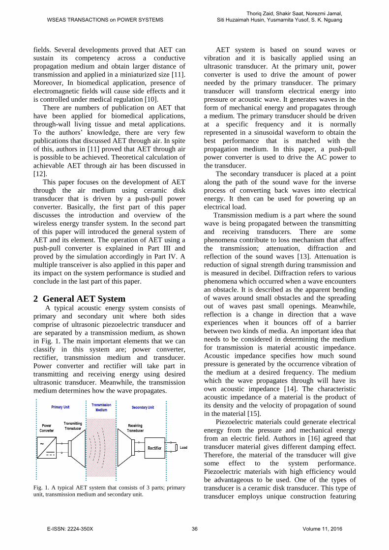
2 General AET System A typical acoustic energy system consists of
primary and secondary unit where both sides
comprise of ultrasonic piezoelectric transducer and
are separated by a transmission medium, as shown
in Fig. 1. The main important elements that we can
classify in this system are; power converter,
rectifier, transmission medium and transducer.
Power converter and rectifier will take part in
transmitting and receiving energy using desired
ultrasonic transducer. Meanwhile, the transmission
medium determines how the wave propagates.
Fig. 1. A typical AET system that consists of 3 parts; primary
unit, transmission medium and secondary unit.
AET system is based on sound waves or
vibration and it is basically applied using an
ultrasonic transducer. At the primary unit, power
converter is used to drive the amount of power
needed by the primary transducer. The primary
transducer will transform electrical energy into
pressure or acoustic wave. It generates waves in the
form of mechanical energy and propagates through
a medium. The primary transducer should be driven
at a specific frequency and it is normally
represented in a sinusoidal waveform to obtain the
best performance that is matched with the
propagation medium. In this paper, a push-pull
power converter is used to drive the AC power to
the transducer.
The secondary transducer is placed at a point
along the path of the sound wave for the inverse
process of converting back waves into electrical
energy. It then can be used for powering up an
electrical load. Transmission medium is a part where the sound
wave is being propagated between the transmitting
and receiving transducers. There are some
phenomena contribute to loss mechanism that affect
the transmission; attenuation, diffraction and
reflection of the sound waves [13]. Attenuation is
reduction of signal strength during transmission and
is measured in decibel. Diffraction refers to various
phenomena which occurred when a wave encounters
an obstacle. It is described as the apparent bending
of waves around small obstacles and the spreading
out of waves past small openings. Meanwhile,
reflection is a change in direction that a wave
experiences when it bounces off of a barrier
between two kinds of media. An important idea that
needs to be considered in determining the medium
for transmission is material acoustic impedance.
Acoustic impedance specifies how much sound
pressure is generated by the occurrence vibration of
the medium at a desired frequency. The medium
which the wave propagates through will have its
own acoustic impedance [14]. The characteristic
acoustic impedance of a material is the product of
its density and the velocity of propagation of sound
in the material [15].
Piezoelectric materials could generate electrical
energy from the pressure and mechanical energy
from an electric field. Authors in [16] agreed that
transducer material gives different damping effect.
Therefore, the material of the transducer will give
some effect to the system performance.
Piezoelectric materials with high efficiency would
be advantageous to be used. One of the types of
transducer is a ceramic disk transducer. This type of
transducer employs unique construction featuring
WSEAS TRANSACTIONS on POWER SYSTEMSThoriq Zaid, Shakir Saat, Norezmi Jamal,
Siti Huzaimah Husin, Yusmarnita Yusof, S. K. Nguang
E-ISSN: 2224-350X 36 Volume 11, 2016

higher sensitivity, wider bandwidth and smaller size
as compared to conventional transducer. As shown
in Fig. 2, the transducer utilized compound vibrator,
which is a conical aluminum resonator with a
connector bonded at the center of the piezoelectric
elements of the bimorph type, consisting of
oppositely polarized material in a sandwich
construction.
Fig 2: Topology of Ceramic-Film Ultrasonic Transducer
When an ultrasonic signal is applied to the
compound vibrator, conical resonator begins to
vibrate effectively because of its shape and drive the
piezoelectric resonator at its central part according
to the frequency of the signal. As a result, the
compound resonator generates a high electrical
signal from the piezoelectric resonator.
Furthermore, formation of standing waves inside the
case results in a higher electrical voltage. If the
resonant frequency of this compound resonator
corresponds to the frequency of the ultrasonic wave
being applied, then the electrical voltage generated
from the piezoelectric resonator is at a maximum
level.
3 Power Converter Design Power converter gives an important role to the
system since it drives the sufficient voltage and
current with specific frequency to transmit energy
through ultrasonic transducer. The recent
development in AET applied different types of
power converter such as in [17] the authors applied
DC power and microcontroller to generate pulse
frequency. In [18], the resonance frequency is
generated from a signal generator and amplified into
the transmitter device.
3.1 Push-pull converter operation Push-pull power converter is chosen because it is
simple and low cost, besides does not need an
additional controller to keep sustain in operation. At
resonance frequency, the push-pull power converter
operates under zero voltage switching (ZVS)
condition, thus it reduces the switching losses
during the operation. The push - pull converter is
designed at the primary unit to deliver power to the
transmitting transducer. This current fed converter
should capable to deliver power to the transducer
before the transducer propagates the energy in a
form of waves to the secondary unit. Basically, the
push-pull converter consists of a phase-splitting
transformer, switches and resonant tank combined
in a circuit as shown in Fig 3. The split-phase
transformer comprises two inductor windings, La
and Lb. The main purpose of this transformer is to
split the received current into two parts, and
smoothed the input ripple current. Thus, the current
will start to oscillate when the force in energy form
enters the resonant tank [19].
Fig. 3. Basic circuit of push-pull converter.
The two switching devices in the push-pull
converter are driven from the voltage on the
opposing pin. Normally, a typical switching device
consists of a diode, resistor, gate capacitor and a
Zener diode for both switches. The advantage of this
system is, no external control circuitry is required to
drive them. The zero voltage switching condition
(ZVS) operation starts when the DC power is
supplied to the input and triggered both of the
switches. Ideally, the voltage across the switches
should be same. ZVS operation ensures that one
switch is activated while the other one is totally in
off condition. Besides that, it can start up
automatically without any control circuit. When the
circuit is functioning, the voltage Va across switch
Sb will be off. This situation also similarly applies to
the voltage Vb across switch SA. Both of this
condition resulting to produce a sinusoidal signal of
output voltage Vab as shown in Fig. 4.
Fig. 4. Output signals of Va, Vb and Vab
WSEAS TRANSACTIONS on POWER SYSTEMSThoriq Zaid, Shakir Saat, Norezmi Jamal,
Siti Huzaimah Husin, Yusmarnita Yusof, S. K. Nguang
E-ISSN: 2224-350X 37 Volume 11, 2016

(3)
(4)
(5)
(6)
(7)
(8)
(9)
(10)
The peak value of the output voltage Vpeak of the
push-pull converter can be calculated as:
,
and the output current (average), I can be expressed
as:
where Vrms is the rms value of the output voltage.
The input of the power converter can calculate as
follows
where ZTX is the transmitter’s impedance. From
[18], the total acoustic output power can be defined
as
∫
∫
The maximum power is usually derived when the
load resistor RL is equal to the internal resistor of
receiver device. The output power is defined by
The efficiency of the energy transfer system can be
calculated as follows
⁄
⁄
3.2 Push-pull converter design The design of the push-pull power converter
should consider several aspects such as frequency,
type of waveform, voltage and current. The process
is initiated by simulation design and analysis
followed by experimental setup. The schematic
circuit of this converter is shown in Fig. 5.
Fig. 5 : Push-pull power converter schematic circuit
TABLE I
Push-pull Converter Circuit Specifications
Parameters Values
Operating Frequency, f 40 kHz
DC Voltage, VDD 5.0V
Resonance Inductance, Lr 33.68uH
Resonance Capacitance, Cr 0.47uF
Table I shows the parameters of the push-pull
converter circuit. In this paper, the operating
frequency will be designated at 40 kHz. This is
because the ceramic disk ultrasonic transducer that
being used in this experiment is optimum at that
particular value based on the initial testing of the
transducer. The frequency of this power converter is
obtained initially from the waveform generated by
the simulation software. The most important
parameter that determines the frequency calculation
is the resonant inductor Lr and capacitor Cr as the
formula, where
√
4 Main Results This section consists of simulation and
experimental results, including the result of AET
performance, which is tested in different conditions.
4.1 Simulation Results The push-pull power converter circuit of Fig. 5
were simulated using Multisim simulation software.
The result is shown in Fig. 6.
Fig. 6. Output waveform of push-pull converter simulation
result
From the simulation result, we can calculate the
frequency of the waveform as follows
The frequency obtained from the simulation is
matched with the resonance frequency required by
the transducer.
WSEAS TRANSACTIONS on POWER SYSTEMSThoriq Zaid, Shakir Saat, Norezmi Jamal,
Siti Huzaimah Husin, Yusmarnita Yusof, S. K. Nguang
E-ISSN: 2224-350X 38 Volume 11, 2016

4.2 Experimental set up of AET System The initial experiment is executed to find the
optimum value of the transducer to transmit energy.
The chosen ultrasonic transducer is 16mm
Matsushita ceramic disk transducer. This transducer
is connected to the function generator and
oscilloscope. The function generator is used to
generate some amount of power and frequency. The
frequency value has been varied to see where the
optimum value of the transducer based on the signal
shown on the oscilloscope. The distance of both
transmitting and receiving transducer is set to a
constant value, 20.0mm. The results of the optimum
frequency are shown in Fig. 7.
Fig. 7: Result of transmitting voltage from function generator
The results in Fig. 7 shows the waveform of the
transmitting voltage where the maximum voltage is
produced at a frequency of 40.32 kHz. The overall
result of the variable frequency vs transfer voltage
amplitude can be seen in Fig. 8.
Fig. 8: Amplitude vs Frequency of the AET initial experiment
The result shows that, at this ≈40 kHz value, the
energy can be transferred at maximum level. The
changes made for even ±1 kHz of frequency would
rapidly decrease the transferred voltage and affect
the performance of the system. This experiment
validated the theoretical explanation that the
resonance frequency of the system should match
with the transducer itself to obtain high efficiency of
energy transfer.
4.3 The Performance of AET System with
Single Transceiver The experimental setup of the AET system is
shown in Fig. 9. The DC input voltage that is
supplied to the push-pull converter circuit is 5V and
connected to the ultrasonic transducer as a
transmitter. The secondary transducer is placed in
opposite and perpendicular to the transmitting
transducer with air gap of 2.0 cm. A simple bridge
rectifier is used in the secondary unit to convert the
received AC voltage to DC voltage. The
arrangement of the power converter, transducers and
rectifier is shown in Fig. 9. The transducer that has
been used in this experiment is Multicomp ceramic
disk ultrasonic transducer and the center frequency
of this component is 40 kHz. Fig. 10 shows the
experimental works of AET system.
Fig. 9: AET basic system using push-pull power converter
transmits energy through the air medium.
Fig. 10 : AET with push-pull converter work station
Based on the equation in (9), the frequency can
be obtained by varying the value of the capacitor
and inductor. In the experiment, there will be slight
error where the value will be a bit different due to
the external factors. It can be observed from Fig. 8
that the result is approximately similar to the
simulation result shown in Fig. 11.
WSEAS TRANSACTIONS on POWER SYSTEMSThoriq Zaid, Shakir Saat, Norezmi Jamal,
Siti Huzaimah Husin, Yusmarnita Yusof, S. K. Nguang
E-ISSN: 2224-350X 39 Volume 11, 2016

Fig. 11: Result of Push-pull power converter on AET
From the result in Fig. 11, the frequency obtained at
the transmitter is 40.75 kHz, which is good
condition to transfer power. The receiving signals
also show that the transmitter and receiver can
transfer energy even though only 45% of the Vpp
voltage were received. The received voltage has
been converted to the DC voltage using rectifier at
different value of load and measured using a digital
multimeter. The result is shown in Fig. 12.
Fig. 12: The optimal power transfer ratio obtained by the
varying the load resistance value. The most optimum value is at
3.3kΩ load resistances where 1.071mW power.
Fig. 13 shows the output power result when the
distance of the air gap is increased. The alignment
of the transducer’s position is constant. In a certain
limit, the output power will be decreased as the air
gap distances increased.
Fig.13: AET system with different air gap between transducers
Since the energy is transferred by wave
propagation, the initial distance would not affect the
performance of the system as long as the alignment
of both transducers is not changed. Due to this fact,
an AET system should be arranged where both
transducers are opposite to each other in a straight
line with constant alignment. Otherwise, the
efficiency will drop off rapidly.
Other than that, when the wave is disturbed by
any obstacle between both of the transducers, the
performance of the energy transfer also decreases
immediately. This is one of the wave phenomena
which is called diffraction of waves. However, if
both of the transducer are attached directly to the
object (without gaps), we can obtain only a lower
reduction of the signals. This is because, the wave is
no longer propagates through air, but it transfers the
ultrasound wave by the vibration through the
medium (object).
The effect of heat in the inductor is not obvious
as much as the increasing heat in a capacitor. Since,
it is affecting the performance of the system, an
additional experiment is executed to carry out the
effect of heat to the capacitor of this push-pull
converter. As the heat of capacitor, Cr is increased,
the value of the capacitance will be decreased
because of changes in the dielectric properties.
Logically, based on the equation (9), the frequency
will be increased as the consequent to the increased
of capacitance.
Fig. 14: The effect of capacitor’s temperature to the frequency
and the transferred power.
The result in Fig.14 shows the increasing of
capacitor’s temperature makes changes in
capacitance value and thus affecting the frequency
and finally decrease the possible power that can be
transferred. From the graph, it is observe that the
WSEAS TRANSACTIONS on POWER SYSTEMSThoriq Zaid, Shakir Saat, Norezmi Jamal,
Siti Huzaimah Husin, Yusmarnita Yusof, S. K. Nguang
E-ISSN: 2224-350X 40 Volume 11, 2016
transferred voltage is decerease when the frequency
is increased to 41kHz. At 41.5kHz, the voltage
transfer is decreased to 0. The built up of heat made
the operation time for perfect energy transfer is
limited.
The power obtained is almost 1.07mW optimum.
Even the achievement is quite low, it still higher
than the previous development in [12] and proved
that the AET system is working with this power
converter design. The efficiency of the system is
14%.
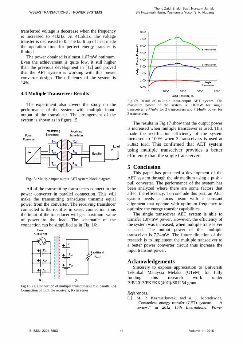
4.4 Multiple Transceiver Results
The experiment also covers the study on the
performance of the system with multiple input-
output of the transducer. The arrangement of the
system is shown as in figure 15.
Fig.15: Multiple input-output AET system block diagram
All of the transmitting transducers connect to the
power converter in parallel connection. This will
make the transmitting transducer transmit equal
power from the converter. The receiving transducer
connected to the rectifier in series connection, thus
the input of the transducer will get maximum value
of power to the load. The schematic of the
connection can be simplified as in Fig. 16:
Fig.16: (a) Connection of multiple transmitters,Tx in parallel (b)
Connection of multiple receivers, Rx in series
Fig.17: Result of multiple input-output AET system. The
maximum power of the system is 1.07mW for single
transceiver, 3.47mW for 2 transceivers and 7.24mW power for
3 transceivers.
The results in Fig.17 show that the output power
is increased when multiple transceiver is used. This
made the rectification efficiency of the system
increased to 100% when 3 transceivers is used at
3.3kΩ load. This confirmed that AET system
using multiple transceiver provides a better
efficiency than the single transceiver.
5 Conclusion This paper has presented a development of the
AET system through the air medium using a push -
pull converter. The performance of the system has
been analyzed where there are some factors that
affect the efficiency. To conclude this part, an AET
system needs a focus beam with a constant
alignment that operate with optimum frequency to
optimize the energy transfer capabilities.
The single transceiver AET system is able to
transfer 1.07mW power. However, the efficiency of
the system was increased, when multiple transceiver
is used. The output power of this multiple
transceiver is 7.24mW. The future direction of the
research is to implement the multiple transceiver to
a better power converter circuit thus increase the
input transmit power.
Acknowledgements Sincerely to express appreciation to Universiti
Teknikal Malaysia Melaka (UTeM) for fully
funding this research work under
PJP/2013/FKEKK(40C)/S01254 grant.
References: [1] M. P. Kazmierkowski and a. J. Moradewicz,
―Contactless energy transfer (CET) systems — A
review,‖ in 2012 15th International Power
WSEAS TRANSACTIONS on POWER SYSTEMSThoriq Zaid, Shakir Saat, Norezmi Jamal,
Siti Huzaimah Husin, Yusmarnita Yusof, S. K. Nguang
E-ISSN: 2224-350X 41 Volume 11, 2016
Electronics and Motion Control Conference
(EPE/PEMC), 2012, pp. Session 3–1–Session 3–6.
[2] H. H. Wu, A. Gilchrist, K. Sealy, P. Israelsen, and
J. Muhs, ―A review on inductive charging for
electric vehicles,‖ 2011 IEEE Int. Electr. Mach.
Drives Conf., pp. 143–147, May 2011.
[3] J. Kim and F. Bien, ―Electric field coupling
technique of wireless power transfer for electric
vehicles,‖ IEEE 2013 Tencon - Spring, vol. 1, pp.
267–271, Apr. 2013.
[4] F. Musavi, M. Edington, and W. Eberle, ―Wireless
power transfer: A survey of EV battery charging
technologies,‖ 2012 IEEE Energy Convers. Congr.
Expo., pp. 1804–1810, Sep. 2012.
[5] E. Waffenschmidt, H. T. Campus, and A. E.
Eindhoven, ―Limitation of inductive power transfer
for consumer applications,‖ Power Electron. Appl.
2009. EPE ’09. 13th Eur. Conf., pp. 1–10, 2009.
[6] A. M. Sodagar and P. Amiri, ―Capacitive Coupling
for Power and Data Telemetry to Implantable
Biomedical Microsystems,‖ Neural Eng. 2009. NER
’09. 4th Int. IEEE/EMBS Conf., pp. 411–414, 2009.
[7] H. Zheng, K. Tnay, N. Alami, and A. P. Hu,
―Contactless Power Couplers for Respiratory
Devices,‖ Mechatronics Embed. Syst. Appl.
(MESA), 2010 IEEE/ASME Int. Conf., pp. 155–160.
[8] A. Sahai and D. Graham, ―Optical wireless power
transmission at long wavelengths,‖ 2011 Int. Conf.
Sp. Opt. Syst. Appl., pp. 164–170, May 2011.
[9] D. E. Raible, D. Dinca, and T. H. Nayfeh, ―Optical
Frequency Optimization of a High Intensity Laser
Power Beaming System Utilizing VMJ Photovoltaic
Cells,‖ Sp. Opt. Syst. Appl. (ICSOS), 2011 Int.
Conf., pp. 232–238, 2011.
[10] G. Calcagnini, F. Censi, and P. Bartolini,
―Electromagnetic immunity of medical devices: the
European regulatory framework.,‖ Ann Ist Super
Sanita 2007, vol. 43, no. 3, pp. 268–276, Jan. 2007.
[11] I. Toshihiko, Y. Kanai, J. Ohwaki, and M. Mino,
―Impact of A Wireless Power Transmission System
Using An Ultrasonic Air Transducer for Low-
Power Mobile Application,‖ Ultrason. 2003 IEEE
Symp., vol. 2, pp. 1368–1371, 2003.
[12] M. G. L. Roes, M. a. M. Hendrix, and J. L. Duarte,
―Contactless energy transfer through air by means
of ultrasound,‖ IECON 2011 - 37th Annu. Conf.
IEEE Ind. Electron. Soc., pp. 1238–1243, Nov.
2011.
[13] M. G. L. Roes, S. Member, J. L. Duarte, M. A. M.
Hendrix, E. A. Lomonova, and S. Member,
―Acoustic Energy Transfer : A Review,‖ IEEE
Trans. Ind. Electron., vol. 60, no. 1, pp. 242–248,
2013.
[14] T. J. Lawry, K. R. Wilt, J. D. Ashdown, H. a
Scarton, and G. J. Saulnier, ―A high-performance
ultrasonic system for the simultaneous transmission
of data and power through solid metal barriers.,‖
IEEE Trans. Ultrason. Ferroelectr. Freq. Control,
vol. 60, no. 1, pp. 194–203, Jan. 2013.
[15] K. Nakamura, Ultrasonic transducers: materials
and design for sensors, actuators and medical
applications. Woodhead Publishing, 2012.
[16] Y. Hu, X. Zhang, J. Yang, and Q. Jiang,
―Transmitting electric energy through a metal wall
by acoustic waves using piezoelectric transducers.,‖
IEEE Trans. Ultrason. Ferroelectr. Freq. Control,
vol. 50, no. 7, pp. 773–81, Jul. 2003.
[17] A. Sanni and A. Vilches, ―Powering low-power
implants using PZT transducer discs operated in the
radial mode,‖ Smart Mater. Struct., vol. 22, no. 11,
pp. 1–12, Nov. 2013.
[18] S. Q. Lee, W. Youm, and G. Hwang,
―Biocompatible wireless power transferring based
on ultrasonic resonance devices,‖ Proc. Meet.
Acoust., vol. 19, pp. 1–9, 2013.
[19] H. H. Wu, A. P. Hu, P. Si, and D. Budgett, ―A
Push-Pull Resonant Converter with Dual Coils for
Transcutaneous Energy Transfer Systems,‖ Ind.
Electron. Appl. 2009. ICIEA 2009. 4th IEEE Conf.,
pp. 1051–1056, 2009.
WSEAS TRANSACTIONS on POWER SYSTEMSThoriq Zaid, Shakir Saat, Norezmi Jamal,
Siti Huzaimah Husin, Yusmarnita Yusof, S. K. Nguang
E-ISSN: 2224-350X 42 Volume 11, 2016