a comparison of accuracies of the rpc models : homo- and
TRANSCRIPT

A COMPARISON OF ACCURACIES OF THE RPC MODELS : HOMO- AND HETERO-
TYPE STEREO PAIRS OF GEOEYE AND WORLDVIEW IMAGES
S. Y. Choi a,*, J. M. Kang b, D. S. Shin a
a 3ATRC-1, ADD, 111, Sunam-dong, Yuseong-gu, Daejeon, 305-152, Korea - (sychoi, dsshin)@add.re.kr
b Dept. of Civil Engineering, Chung-Nam National Uni., Yuseong-gu, Daejeon, 305-763, Korea - [email protected]
Commission IV, WG IV/3
KEY WORDS: Accuracy, RPC Model, Homo-type stereo, Hetero-type stereo, GeoEye-1 images, WorldView-2 images
ABSTRACT:
We investigated the accuracy in three dimensional geo-positioning derived by two homo-type stereo pairs and four hetero-type stereo
pairs of high resolution satellite images using the vendor-provided rational polynomial coefficients (RPC) in this research. The
results of 3D geo-positioning from six different stereo combinations were assessed with seventeen GPS points which were
commonly well distributed in the scenes. Recently, satellite image vendors provide homo-type stereo pair images taken by the same
sensor during a short time period. Stereo pair images have good geometry for achieving accurate ground coordinates. However it is
difficult to acquire them at the request time because of the revisit time of the satellite and current weather conditions. Due to these
reasons, a new methodology using hetero-type stereo pairs has been suggested to derive ground coordinates. High resolution satellite
images include the rational function model in the form of RPC which represents the relationship between the image coordinates and
object coordinates with rational polynomials. RPC makes it fast, accurate, and simple to calculate ground coordinates without any
exterior orientation parameters of satellites. We constituted six different stereo pairs from four images of GeoEye-1 in-track stereo
pair images and WorldView-2 in-track stereo pair images which were collected for the same region (17.5km x 10.0km) of the west
coast in Korea. We collected GCPs by differential GPS surveying. The ground coordinates derived from six different pairs without
and with some GCPs were compared to all GPS points respectively. The accuracy of ground coordinates from hetero-type stereo
pairs is equivalent to the accuracy from homo-type stereo pairs. This research demonstrates that we can achieve comparatively
accurate ground coordinates without GCPs using any stereo combinations of images containing proper RPCs, although we don't have
in-track stereo pair images. Furthermore, some proper combinations of images with GCPs can improve the positioning accuracy.
1. INTRODUCTION
Since IKONOS was launched in 1999 and provided publicly
available high-resolution imagery at 1- and 4-meter resolution,
high resolution satellite imagery has become indispensible for
aspects of various areas such as urban management, large scale
map development, etc.
Recently GeoEye-1 and WorldView-2 satellites have provided
high resolution (0.5m) in-track stereo-pair images. As in-track
stereo pair is taken from two different perspectives during one
orbital pass, in-track stereo data acquisition has a strong
advantage over multi-date cross-track stereo data acquisition. It
reduces radiometric image variations (temporal changes, sun
illumination, etc.), and thus increases the correlation success
rate in any image matching process (Toutin, 2004).
In addition, when using high resolution satellite imagery for
topographic mapping, in-track stereo pair images can ensure the
geometric accuracy of generated DSM. However with respect
to spatial information collection, the limitation such as
expensive data acquisition fee, insufficiency of imaging regions
and archived data is apparent (Zhu, 2008). Provided the images
acquired from various satellite sensors are available, the full
exploitation of these images will extend the possibility of spatial
information collection, cut down expenses, and save time to
prepare taking photographs.
Most of recent satellite images such as GeoEye-1 and
WorldView-2 images provide a rational polynomial coefficient
(RPC) model which is a kind of generic sensor model that is
widely used in the processing of high-resolution satellite images.
Unlike traditional physical camera models, an RPC model has
80 coefficients and simulates the sensor’s position, attitude, and
interior orientation, so the RPC model has no physical
interpretation and is applicable to any images regardless of an
acquisition sensor. This means hetero-type stereo pairs can be
used for determining the precise position. In this paper, there are
two kinds of stereo pairs. One is homo-type stereo pairs that is a
stereo model using stereo pairs acquired from the same sensor,
and the other is hetero-type stereo pairs that is a stereo model
using stereo pairs acquired from different sensors.
There have been not many studies for regarding the application
of high resolution satellite hetero-type stereo pairs. Zhu
investigated the geometric accuracy of DSMs and orthoimages,
which were obtained from homo-type and hetero-type stereo
pairs of four IKONOS and two QuickBird panchromatic images,
in 2008.
In this study, two kinds of homo-type stereo pairs and 4 kinds of
hetero-type stereo pairs were used to make RPC stereo models
using in-track stereo pairs of GeoEye-1 images and in-track
stereo pairs of WorldView-2 images. We investigated the
accuracy in three dimensional geo-positioning without and with
GCPs for each 6 stereo pairs. The stereo acquisition geometry
of the stereo pairs is used to analyze the relationship between
the geometric accuracy of the RPC model and the geometric
parameter such as B/H (Base to Height) ratio, BIE (Bisector
Elevation Angle), and CA (Convergence Angle) (Zhu, 2008,
Tong, 2008). The results show that RPC models of any stereo
pairs of high resolution satellite stereo images have the potential
to be used for three dimensional geo-positioning.
2. DATASETS AND RPC MODELS
ISPRS Annals of the Photogrammetry, Remote Sensing and Spatial Information Sciences, Volume I-4, 2012 XXII ISPRS Congress, 25 August – 01 September 2012, Melbourne, Australia
65
For this study, GeoEye-1 and WorldView-2 in
covering the same area of the west coast of
The test area covers both high and low altitudes. Table 1 shows
the properties of the used satellite images.
Sensor GeoEye-1 Image ID GE_01 GE_02 WV_01Product Geo Stereo
Scan direction
Reverse Reverse Reverse
Resolution 0.5m 0.5m 0.65m
Azimuth 345.3° 219.2° 169.3
Elevation 68.7° 66.3° 51.6
Date(GMT) 2010.4.25
02:30 2010.4.25
02:31 2010.4.23
02:28
Table 1. Properties of the used satellite images
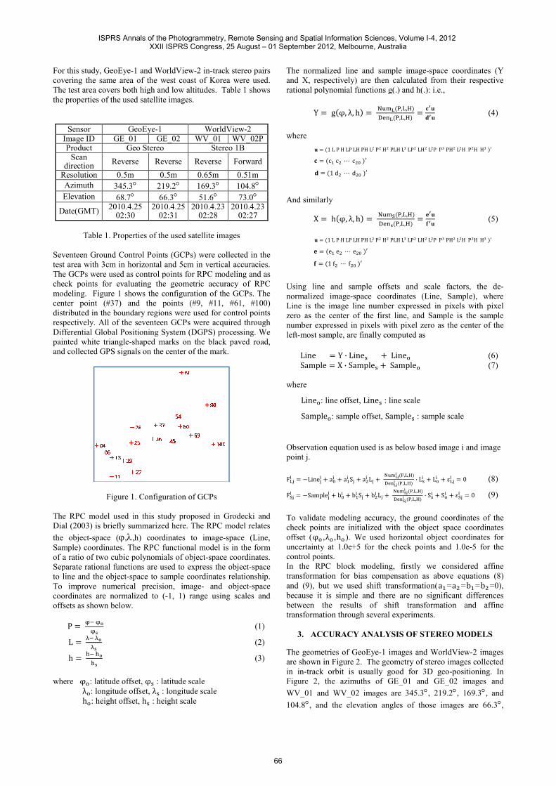
Seventeen Ground Control Points (GCPs) were collected in the
test area with 3cm in horizontal and 5cm in vertical
The GCPs were used as control points for RPC modeling and
check points for evaluating the geometric accuracy of RPC
modeling. Figure 1 shows the configuration of the GCPs.
center point (#37) and the points (#9,
distributed in the boundary regions were used for control points
respectively. All of the seventeen GCPs were acquired through
Differential Global Positioning System (DGPS) processing.
painted white triangle-shaped marks on the black paved road,
and collected GPS signals on the center of the mark.
Figure 1. Configuration of GCPs
The RPC model used in this study proposed in Grodecki and
Dial (2003) is briefly summarized here. The RPC model
the object-space (ϕ,λ,h) coordinates to image
Sample) coordinates. The RPC functional model is in the
of a ratio of two cubic polynomials of object
Separate rational functions are used to express the
to line and the object-space to sample coordinates
To improve numerical precision, image
coordinates are normalized to (-1, 1) range
offsets as shown below.
P � �� ����
L � � ��
h � �� ����
where φ : latitude offset, φ� : latitude scale
λ : longitude offset, λ� : longitude scale
h : height offset, h� : height scale
2 in-track stereo pairs
of Korea were used.
he test area covers both high and low altitudes. Table 1 shows
WorldView-2 WV_01 WV_02P
Stereo 1B
Reverse Forward
0.65m 0.51m
169.3° 104.8°
51.6° 73.0° 2010.4.23
02:28 2010.4.23
02:27
1. Properties of the used satellite images
Ground Control Points (GCPs) were collected in the
and 5cm in vertical accuracies.
used as control points for RPC modeling and as
check points for evaluating the geometric accuracy of RPC
modeling. Figure 1 shows the configuration of the GCPs. The
9, #11, #61, #100)
distributed in the boundary regions were used for control points
GCPs were acquired through
Differential Global Positioning System (DGPS) processing. We
shaped marks on the black paved road,
r of the mark.
Figure 1. Configuration of GCPs
RPC model used in this study proposed in Grodecki and
The RPC model relates
,h) coordinates to image-space (Line,
coordinates. The RPC functional model is in the form
two cubic polynomials of object-space coordinates.
Separate rational functions are used to express the object-space
oordinates relationship.
To improve numerical precision, image- and object-space
range using scales and
(1)
(2)
(3)
: latitude scale
: longitude scale
The normalized line and sample image
and X, respectively) are then calculated from their respec
rational polynomial functions g(.) and h(.): i.e.,
Y � g�φ, λ, h� � ������,������,�
where
� � �1 L P H LP LH PH L! P! H! PLH L " � �c$ c! % c!& �' ( � �1 d! % d!& �'
And similarly
X � h�φ, λ, h� � ���+��,������,�
� � �1 L P H LP LH PH L! P! H! PLH L , � �e$ e! % e!& �' . � �1 f! % f!& �'
Using line and sample offsets and scale factors, the de
normalized image-space coordinates
Line is the image line number expressed in pixels with pixel
zero as the center of the first line, and Sample is the sample
number expressed in pixels with pixel zero
left-most sample, are finally computed as
Line � Y · Line� 3 Line Sample � X · Sample� 3 Sample where
Line : line offset, Line� : line scale
Sample : sample offset, Sample
Observation equation used is as below based image
point j.
F�:; � <Line:; 3 a&; 3 a$; S: 3 a!; L: 3 ����=> ������=> ��
F?:; � <Sample:; 3 b&; 3 b$; S: 3 b!; L: 3 ������
To validate modeling accuracy, the ground coordinates of the
check points are initialized with the object space coordinates
offset (φ ,λ ,h ). We used horizontal object coordinates
uncertainty at 1.0e+5 for the check points and 1.0e
control points.
In the RPC block modeling, firstly we considered affine
transformation for bias compensation
and (9), but we used shift transformation
because it is simple and there are
between the results of shift
transformation through several experiments.
3. ACCURACY ANALYSIS OF
The geometries of GeoEye-1 images and WorldView
are shown in Figure 2. The geometry of stereo images collected
in in-track orbit is usually good for 3D geo
Figure 2, the azimuths of GE_01 and
WV_01 and WV_02 images are 345.3
104.8°, and the elevation angles of those images are 66.3
The normalized line and sample image-space coordinates (Y
and X, respectively) are then calculated from their respective
rational polynomial functions g(.) and h(.): i.e.,
,�,A��,A� � "B�
(B� (4)
LC LP! LH! L!P PC PH! L!H P!H HC �'
,�,A��,A� � ,B�
.B� (5)
LC LP! LH! L!P PC PH! L!H P!H HC �'
Using line and sample offsets and scale factors, the de-
space coordinates (Line, Sample), where
Line is the image line number expressed in pixels with pixel
zero as the center of the first line, and Sample is the sample
number expressed in pixels with pixel zero as the center of the
most sample, are finally computed as
Line (6) Sample (7)
: line scale
Sample� : sample scale
Observation equation used is as below based image i and image
�,�,A��,�,A� · L�; 3 L ; 3 ε�:; � 0 (8)
���+=> ��,�,A����+=> ��,�,A� · S�; 3 S ; 3 ε?:; � 0 (9)
the ground coordinates of the
with the object space coordinates
We used horizontal object coordinates for
1.0e+5 for the check points and 1.0e-5 for the
RPC block modeling, firstly we considered affine
compensation as above equations (8)
transformation(a$ =a! =b$ =b! =0),
there are no significant differences
transformation and affine
through several experiments.
ACCURACY ANALYSIS OF STEREO MODELS
1 images and WorldView-2 images
are shown in Figure 2. The geometry of stereo images collected
usually good for 3D geo-positioning. In
igure 2, the azimuths of GE_01 and GE_02 images and
WV_01 and WV_02 images are 345.3°, 219.2°, 169.3°, and
, and the elevation angles of those images are 66.3°,
ISPRS Annals of the Photogrammetry, Remote Sensing and Spatial Information Sciences, Volume I-4, 2012 XXII ISPRS Congress, 25 August – 01 September 2012, Melbourne, Australia
66

68.7°, 51.6°, and 73.0° respectively. Any combination of stereo
image pairs has good geometry to perform geolocation via
spatial intersection.
a) Satellite Azimuths b) Satellite Elevation
Figure 2. Image Geometry
3.1 Geometry of Satellites
It is clear that a geometric stereo model needs to be
with respect to the relationship between the stereo acquisition
geometry and the geometric accuracy in a variable geometric
environment (Cain, 1989). There are some
to express the geometry. The B/H ratio is the ratio of the length
between the two satellites to the average flying altitude above
ground level. The B/H ratio has been widely used in
triangulation. However, the B/H ratio is not
measure of the geometry for the satellite stereo models
should consider the curvature of the earth (Li, 2008).
the angle that represents how much the epipolar plane rotates
about flight line. The CA is the angle between the two rays in
the convergence or epipolar plane. An angle between 30 and 60
degrees is ideal. The AA is the apparent offset
view that a stereo pair has and should be under 20 deg
(GEOIMAGE, 2010).
We used only B/H ratio and BIE that are the important
parameters related to the accuracy of satellite stereo models
(Zhu, 2008) . Figure 3 shows the geometry of two satellites
which is used in this study. We set up a local
coordinate system where the origin is the centre of the scene.S$ and S! are the positions of two satellites.
the satellite orbit above ground level, R is the radius of the earth, e; is the elevation of the satellite i, and Az; is the azimuth of the
satellite i. We can find the positions of two satellites
(11).
Figure 3. Geometry of Satellites
respectively. Any combination of stereo
image pairs has good geometry to perform geolocation via
atellite Elevations
Figure 2. Image Geometry
needs to be analyzed
the relationship between the stereo acquisition
geometry and the geometric accuracy in a variable geometric
some kinds of parameters
The B/H ratio is the ratio of the length
between the two satellites to the average flying altitude above
ground level. The B/H ratio has been widely used in the aerial
the B/H ratio is not appropriate as a
stereo models which
(Li, 2008). The RA is
the angle that represents how much the epipolar plane rotates
between the two rays in
An angle between 30 and 60
the apparent offset from the centre
should be under 20 deg
used only B/H ratio and BIE that are the important
racy of satellite stereo models
(Zhu, 2008) . Figure 3 shows the geometry of two satellites
e set up a local Cartesian
coordinate system where the origin is the centre of the scene.
are the positions of two satellites. H is the altitude of
, R is the radius of the earth,
is the azimuth of the
e can find the positions of two satellites in (10) and
Figure 3. Geometry of Satellites
S$ � HX$Y$Z$J � HOS$ · cos e$ ·OS$ · cos e$ ·OS$ · sin
S! � HX!Y!Z!J � HOS! · cos e!OS! · cos e!OS! · sin
Baseline (B) and B/H ratio can be derived by formulas (12) and
(13).
B � lengthPS$S!Q � R�X$ < X!�!3
B/H ratio � UVWXVYY
Equation (14) shows how we calculate BIE.
u$ � [?W\\\\\\\\]^[?W\\\\\\\\]^ , u! � [?Y\\\\\\\\]
^[?Y\\\\\\\\]^
BIE � sin�$ a �W\\\\]b�Y\\\\]|�W\\\\]b�Y\\\\]| · z]d
3.2 Bias of pixel in forward RPC
Biases in RPCs generated from sensor orientation, which are
generally attributed to small systematic errors in gyro and star
tracker recordings, have been shown to be adequately
by zero-order shifts in image space
shows these biases quantified by differences between
computing image coordinates via the RP
coordinates of the GPS points. It can be seen that, although the
mean of discrepancies are -0.4 ~ 3.8 pixels, the standard er
of differences are less than 0.37 pixels. This instance is to show
that compensating image biases inherent in RPCs can increase
geopositioning accuracies.
GE_01
WV_01
Figure 3. Bias vectors of
Images RMSE MEAN
Line Sample Line
GE_01 3.846 0.440 3.842
GE_02 0.861 0.535 0.781
WV_01 2.049 1.360 2.029
WV_02 3.625 0.873 3.612
Table 2. Biases of the image
· sin Az$· cos Az$sin e$J (10)
· sin Az!· cos Az!sin e!J (11)
and B/H ratio can be derived by formulas (12) and
� 3�Y$ < Y!�! 3 �Z$ < Z!�! (12)
(13)
quation (14) shows how we calculate BIE.
(14)
pixel in forward RPC
Biases in RPCs generated from sensor orientation, which are
generally attributed to small systematic errors in gyro and star
tracker recordings, have been shown to be adequately modeled
order shifts in image space (Fraser, 2009). Figure 3
shows these biases quantified by differences between
computing image coordinates via the RPCs and measured image
points. It can be seen that, although the
~ 3.8 pixels, the standard errors
pixels. This instance is to show
that compensating image biases inherent in RPCs can increase
GE_02
WV_02
of image coordinates
MEAN S.D.
Line Sample Line Sample
3.842 -0.398 0.188 0.194
0.781 0.450 0.373 0.297
2.029 -1.345 0.300 0.206
3.612 -0.840 0.312 0.245
image coordinates
ISPRS Annals of the Photogrammetry, Remote Sensing and Spatial Information Sciences, Volume I-4, 2012 XXII ISPRS Congress, 25 August – 01 September 2012, Melbourne, Australia
67

3.3 Accuracy of Stereo Models
Figure 4 shows ground coordinate biases in RPC sensor
orientation for the homo- and hetero-type stereo models without
GCPs. The worst systematic bias errors in object points of
-0.3m in easting and -2.1m in northing at the ‘GE_01 and
WV_02’ stereo pair and 2.2m in height at the ‘GE_01 and
GE_02’ stereo pair resulted. In any case of all six stereo pairs,
there are shift bias patterns in both planimetry and height
regardless of homo-type or hetero-type stereos.
GE_01 and GE_02 GE_01 and WV_01
GE_01 and WV_02 GE_02 and WV_01
GE_02 and WV_02 WV_01 and WV_02
Figure 4. Residuals of stereo models without GCPs
Figure 5 shows the residuals of the six stereo models using
single GCP(#37) located in the middle of the test area. Only
one GCP compensates bias error efficiently and the accuracies
are remarkably improved to 0.39 meters in CEP(90) and 0.62
meters in LEP(90). However, the random errors exist in the
RPC models provided with the GCP.
GE_01 and GE_02 GE_01 and WV_01
GE_01 and WV_02 GE_02 and WV_01
GE_02 and WV_02 WV_01 and WV_02
Figure 5. Residuals of stereo models with single GCP
Figure 6 shows ground coordinate biases in RPC sensor
orientation for the six stereo models using four well distributed
GCPs(#9, #11, #61, #100). The accuracy of this case has a
strong resemblance to that of the single GCP.
GE_01 and GE_02 GE_01 and WV_01
GE_01 and WV_02 GE_02 and WV_01
GE_02 and WV_02 WV_01 and WV_02
Figure 6. Residuals of stereo models with four GCPs
3.4 Results and Discussions
Table 3 shows the results of our investigation. The geometric
accuracy is assessed in planimetry and height using no GCP, 1
GCP, and 4 GCP respectively. The accuracy of stereo models
dramatically improved with only one GCP, however when we
used more GCPs, the accuracy slightly increased. Regarding
stereo types, it was concluded that there is no significant
difference in accuracy between homo-type and hetero-type
stereo pairs if they have good stereo geometry such as B/H, and
BIE. In the case of ‘GE_02 and WV_02’ hetero-type stereo pair,
planimetry accuracy without GCP is the best.
Image
pairs B/H BIE
No GCP 1 GCP 4 GCPs
CEP
(90)
LEP
(90)
CEP
(90)
LEP
(90)
CEP
(90)
LEP
(90)
GE_01 &
GE_02 0.74 79.3 1.33 2.53 0.25 0.53 0.25 0.62
GE_01 &
WV_01 1.16 81.4 1.35 2.07 0.24 0.41 0.21 0.38
GE_01 &
WV_02 0.69 79.9 2.25 0.76 0.20 0.38 0.19 0.46
GE_02 &
WV_01 0.61 61.3 1.24 2.13 0.30 0.48 0.26 0.53
GE_02 &
WV_02 0.73 78.3 0.69 1.56 0.39 0.62 0.29 0.51
WV_01 &
WV_02 0.71 65.5 1.60 2.39 0.37 0.57 0.33 0.58
Table 3. Accuracy of Stereo Models
4. CONCLUSION
In this study, GeoEye-1 in-track stereo pair and WorldView-2
in-track stereo pair were collected in the same region. We
compared the three-dimensional geopositioning accuracy of
different combinations from these four images. According to
the results in table 3, the following conclusions can be
confirmed.
ISPRS Annals of the Photogrammetry, Remote Sensing and Spatial Information Sciences, Volume I-4, 2012 XXII ISPRS Congress, 25 August – 01 September 2012, Melbourne, Australia
68

� In-track stereo pairs of GeoEye-1 and WorldView-2
are meaningfully accurate for developing geo-spatial
information for a map of 1/5,000 without any GCPs.
� The accuracies of hetero-type stereo pairs which have
good geometry(B/H and BIE) are as accurate as that
of homo-type in-track stereo pairs.
� The hetero-type stereo pair model of the images with
different ground sample distances could be
comparatively accurate, because RPC model is
independent on sensors.
References :
Cain, J. 1989, Stereomodel Acquisition Geometry, Ph.D. thesis,
U.C. Berkeley.
Fraser, C.S. and Hanley, H.B., 2003. Bias Compensation in
Rational Functions for Ikonos Satellite Imagery,
Photogrammetric Engineering & Remote Sensing, 69(1), pp.
53-57
Fraser, C.S. and Ravanbakhsh, M., 2009. Georeferencing
accuracy of GeoEye-1 imagery, Photogrammetric Engineering
& Remote Sensing, 75(6), pp. 634- 640.
GEOIMAGE, 2010, “Digital Elevation Models from Satellite
Imagery”.
http://www.geoimage.com.au/geoimage/uploads/Geoimage_DE
M_brochure_Oct10_small_lowres.pdf
Grodecki, J. and Dial, G., 2003. Block adjustment of high-
resolution satellite images described by rational polynomials,
Photogrammetric Engineering & Remote Sensing, 69(1), pp.
59-68.
Li, J., Shao, Y., Wang, J., and Yang, J.(2008), The Research
and Design of The Base-Height Ratio for the Three Linear
Array Camera of Satellite Photogrammetry, The International
Archives of the Photogrammetry, Remote Sensing and Spatial
Information Sciences, Vol. XXXVII.Part B1.Beijing, pp. 757-
760
Li, R., Zhou, F., Niu, X., and Di, K., 2007. Integration of Ikonos
and QuickBird Imagery for Geopositioning Accuracy Analysis,
Photogrammetric Engineering & Remote Sensing, 73(9), pp.
1067-1074.
NIMA, 2000, The Compendium of Controlled Extensions for
the National Imagery Transmission Format, ver. 2.1.
Toutin, T., 2004. DTM Generation from Ikonos In-Track Stereo
Images Using a 3D Physical Model, Photogrammetric
Engineering & Remote Sensing, 70(6), pp. 695–702.
Zhu, L., Umakawa, H., Guan, F., Tachibana, K., and
Shimamura, H., 2008. Accuracy Investigation of Orthoimages
Obtained from High Resolution Satellite Stereo Pairs, The
International Archives of the Photogrammetry, Remote Sensing
and Spatial Information Sciences, Beijing, Vol. XXXVII. Part
B1. pp.1145-1148
ISPRS Annals of the Photogrammetry, Remote Sensing and Spatial Information Sciences, Volume I-4, 2012 XXII ISPRS Congress, 25 August – 01 September 2012, Melbourne, Australia
69