a comparative study of dielectric properties of … comparative study of dielectric properties of...
TRANSCRIPT
International Journal of Engineering Technology, Management and Applied Sciences
www.ijetmas.com April 2015, Volume 3 Issue 4, ISSN 2349-4476
303 S. Moharana, M. K. Mishra, B. Behera, R.N Mahaling
A Comparative Study of Dielectric Properties of Calcined and
Un-Calcined BiFeO3-Poly (vinylidene fluoride) (PVDF)
Composite Films
S. Moharana1, M. K. Mishra
1, B. Behera
2, R.N Mahaling
1*(Corresponding Author)
1Polymeric and Materials Chemistry Laboratory, School of Chemistry, Sambalpur University,
Jyoti Vihar, Burla-768019, Odisha, India 2Materials Research Laboratory, School of Physics, Sambalpur University,
Jyoti Vihar, Burla - 768019, Odisha, India
Abstract
In the present study, the dielectric properties of calcined and uncalcined BiFeO3 with polyvinylidene
fluoride (PVDF) composite film are studied. The structure, morphology and dielectric properties are
studied by X-ray diffraction, Scanning Electron Microscope and impedance analyser. From X-ray
diffraction pattern it is found that calcined BiFeO3 with PVDF composite confirms the rhombohedral
structure but there is no clear diffraction peak in support of (structure of) uncalcined BiFeO3 with
PVDF composite film. The dielectric constant of the uncalcined BiFeO3 with PVDF composite at RT
is very high i.e., 200, which is 20 times higher than that of calcined and pure PVDF film. The
complex impedance spectroscopy shows the electrical properties of the composites which are studied
by using wide range of frequency at room temperature. The Nyquist plot suggests the contribution of
bulk and grain boundary effect with reference to the electrical impedance. The surface morphology
(SEM) reveals that the calcined PVDF/BiFeO3 composite film has an average grain size of 600 -700
nm, which is much lesser than the uncalcined composite film. The value of exponent n, pre-factor A
and ζdc are calculated by taking the reference of ζac conductivity data which obeys the Jonscher’s
universal power law.
Key words: Polymer, composite, Poly (vinylidene fluoride), X- ray diffraction, dielectric properties,
electrical conductivity.
1. Introduction
In the past few decades, the high dielectric constant polymer based composite materials have
attracted more attention because of their vast area of potential applications in electronic devices and
in electrical industry such as gate dielectrics, dynamic random access memory, miniature capacitor
for telecommunications, actuators, transducers and energy storage devices [1-4]. A ferroelectric
ceramic material such as BaTiO3 (BT), Lead Zirconate Titanate (PZT), CaCu3Ti4O12 (CCTO),
Pb(Mg1/3Nb2/3)O3–PbTiO3 (PMN–PT) show high dielectric constant and are commonly used as
voltage capacitors due to their high breakdown voltage. Ceramic materials also exhibit poor
mechanical strength, bad energy storage capacity and are brittle in nature [5-7]. On the other hand,
polymers such as Poly(vinylidene fluoride) (PVDF), Polypropylene (PP), Polyethylene terephthalate
(PET), Polyethylene (PE) and Polystyrene (PS) are composite materials with low density, low
weight, low cost, good flexibility, elasticity, relatively low dielectric constant, high electrical
breakdown strength and high dielectric loss [5,6,8-10]. Generally, it is used in low leakage capacitors
[5, 11]. Thus, the combination of both the ceramic particles and polymers produce new composite
material with high dielectric constant and high breakdown voltage which can be efficiently used for
high energy density capacitor applications [12-14]. Recently, many researchers are keenly interested

International Journal of Engineering Technology, Management and Applied Sciences
www.ijetmas.com April 2015, Volume 3 Issue 4, ISSN 2349-4476
304 S. Moharana, M. K. Mishra, B. Behera, R.N Mahaling
in polymer ceramic composite materials due to their fascinating properties such as mechanical,
thermal, electrical and its fabrication as compared to their individual components and they can be
used in various commercial technological applications such as transducers, dielectric memories and
sensors etc. [15-17].
In this study, the ceramic material like BiFeO3 (BFO) belongs to the novel multiferroic
family shows various special properties. It is a single phase material having both ferroelectric and
anti-ferromagnetic natures simultaneously so it is known as multiferroics [18-19]. Usually, properties
of multiferroics include ferroelectricity, ferromagnetism and ferrotoroidicity [20-21]. This type of
multiferroic material has wide range of applications such as in spintronics, smart sensor devices,
multistate memory devices, data storage media, memory elements, tunable microwave devices etc
[22-23]. Generally, very few materials are ferroelectric and ferromagnetic, but in room temperature
the magnetoelectric couplings are very weak [24-25]. Recently, D. Bhadra and S. Sarkar research
groups [1] have extensively studied the dielectric properties of BiFeO3-PVDF composite film which
reveals high dielectric constant and low loss tangent.
In our work, the polymeric materials we have used to prepare the composite film are poly
(vinylidene fluoride) and the multiferroic material BiFeO3. Here PVDF is chosen as the polymer host
because it is a well-known material having high dielectric constant which can be easily processed.
They have numerous applications in pyroelectric, piezoelectric, transducers and actuators [26-28, 1].
Generally, PVDF is a semicrystaline polymer with complicated structure and also forms different
crystalline phases (α, β, γ and δ). The most common polymorph i.e. α phase is an electrically inactive
non-polar phase, while the other phases are electrically active polar [29-30]. Normally, they have a
chain like linear structure i.e. [-CH2-CF2-] and are formed by free radical polymerization. It has low
piezo, pyro-electric coefficient and dielectric constant while the ceramics have high piezo, pyro-
electric coefficient and dielectric constants [1]. Due to this reason, the polymer composites have
become an ultimate substitute for both classes as they possess useful properties of both materials.
The general objective of this study is to compare the efficacy of calcined and uncalcined BiFeO3
with PVDF composite to investigate the effects of the quantity of BiFeO3 loaded. In recent years,
several reports show the dielectric properties of calcined BiFeO3 with PVDF composite. However, to
the best of our knowledge, there is no report till now on dielectric properties of uncalcined BiFeO3
with PVDF composite.
Therefore in this paper we have examined the effect of dielectric behaviour of calcined and
uncalcined BiFeO3 with PVDF composite film.
2. Experimental details
2.1. Materials Semi-crystalline polymer Poly (vinylidene fluoride) (PVDF) was purchased from Alfa Aesar.
Bismuth Oxide (Bi2O3) 99.5% purity and Iron Oxide (Fe2O3) 99% purity, were obtained from Merck,
India. The solvent N, N-Dimethylformamide (DMF,>99.0%) was supplied from Loba Chemie PVT,
Ltd., India. All these chemicals were used as received without further purification. Deionised water
was used throughout the experiment.
2.2. Preparation of Bismuth Ferrite Powder
BiFeO3 ceramic was prepared by the conventional solid state reaction method. The equi-molar
mixture of Bi2O3 and Fe2O3 were mixed thoroughly in agate mortar in an air atmosphere for 2 h and
then in alcohol for another 2 hour. The mixed powders were calcined in a high purity alumina
crucible at an optimized temperature of 800oC for 4h in a high-purity alumina crucible.
International Journal of Engineering Technology, Management and Applied Sciences
www.ijetmas.com April 2015, Volume 3 Issue 4, ISSN 2349-4476
305 S. Moharana, M. K. Mishra, B. Behera, R.N Mahaling
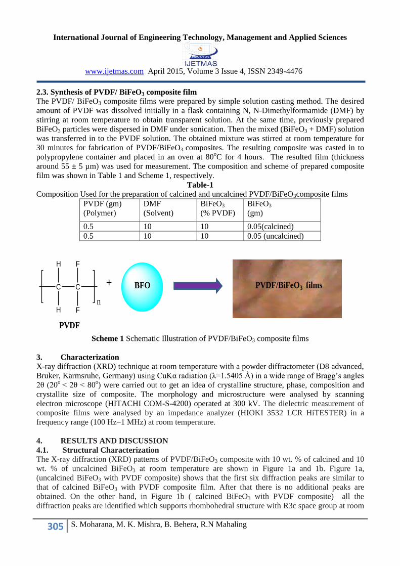
2.3. Synthesis of PVDF/ BiFeO3 composite film The PVDF/ BiFeO3 composite films were prepared by simple solution casting method. The desired
amount of PVDF was dissolved initially in a flask containing N, N-Dimethylformamide (DMF) by
stirring at room temperature to obtain transparent solution. At the same time, previously prepared
BiFeO3 particles were dispersed in DMF under sonication. Then the mixed (BiFeO3 + DMF) solution
was transferred in to the PVDF solution. The obtained mixture was stirred at room temperature for
30 minutes for fabrication of PVDF/BiFeO3 composites. The resulting composite was casted in to
polypropylene container and placed in an oven at 80oC for 4 hours. The resulted film (thickness
around 55 ± 5 µm) was used for measurement. The composition and scheme of prepared composite
film was shown in Table 1 and Scheme 1, respectively.
Table-1
Composition Used for the preparation of calcined and uncalcined PVDF/BiFeO3composite films
PVDF (gm)
(Polymer)
DMF
(Solvent)
BiFeO3
(% PVDF)
BiFeO3
(gm)
0.5 10 10 0.05(calcined)
0.5 10 10 0.05 (uncalcined)
Scheme 1 Schematic Illustration of PVDF/BiFeO3 composite films
3. Characterization
X-ray diffraction (XRD) technique at room temperature with a powder diffractometer (D8 advanced,
Bruker, Karmsruhe, Germany) using CuKα radiation (λ=1.5405 Å) in a wide range of Bragg’s angles
2θ (20o
< 2θ < 80o) were carried out to get an idea of crystalline structure, phase, composition and
crystallite size of composite. The morphology and microstructure were analysed by scanning
electron microscope (HITACHI COM-S-4200) operated at 300 kV. The dielectric measurement of
composite films were analysed by an impedance analyzer (HIOKI 3532 LCR HiTESTER) in a
frequency range (100 Hz–1 MHz) at room temperature.
4. RESULTS AND DISCUSSION
4.1. Structural Characterization
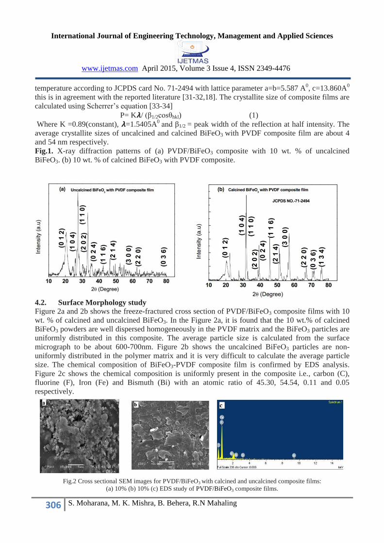
The X-ray diffraction (XRD) patterns of PVDF/BiFeO3 composite with 10 wt. % of calcined and 10
wt. % of uncalcined BiFeO3 at room temperature are shown in Figure 1a and 1b. Figure 1a,
(uncalcined BiFeO3 with PVDF composite) shows that the first six diffraction peaks are similar to
that of calcined BiFeO3 with PVDF composite film. After that there is no additional peaks are
obtained. On the other hand, in Figure 1b ( calcined BiFeO3 with PVDF composite) all the
diffraction peaks are identified which supports rhombohedral structure with R3c space group at room
C C
FH
H F
n
PVDF
PVDF/BiFeO3 filmsBFO+
International Journal of Engineering Technology, Management and Applied Sciences
www.ijetmas.com April 2015, Volume 3 Issue 4, ISSN 2349-4476
306 S. Moharana, M. K. Mishra, B. Behera, R.N Mahaling
temperature according to JCPDS card No. 71-2494 with lattice parameter a=b=5.587 A0, c=13.860A
0
this is in agreement with the reported literature [31-32,18]. The crystallite size of composite films are
calculated using Scherrer’s equation [33-34]
P= K𝞴/ (β1/2cosθhkl) (1)
Where K =0.89(constant), 𝞴=1.5405A0
and β1/2 = peak width of the reflection at half intensity. The
average crystallite sizes of uncalcined and calcined BiFeO3 with PVDF composite film are about 4
and 54 nm respectively.
Fig.1. X-ray diffraction patterns of (a) PVDF/BiFeO3 composite with 10 wt. % of uncalcined
BiFeO3. (b) 10 wt. % of calcined BiFeO3 with PVDF composite.
4.2. Surface Morphology study Figure 2a and 2b shows the freeze-fractured cross section of PVDF/BiFeO3 composite films with 10
wt. % of calcined and uncalcined BiFeO3. In the Figure 2a, it is found that the 10 wt.% of calcined
BiFeO3 powders are well dispersed homogeneously in the PVDF matrix and the BiFeO3 particles are
uniformly distributed in this composite. The average particle size is calculated from the surface
micrograph to be about 600-700nm. Figure 2b shows the uncalcined BiFeO3 particles are non-
uniformly distributed in the polymer matrix and it is very difficult to calculate the average particle
size. The chemical composition of BiFeO3-PVDF composite film is confirmed by EDS analysis.
Figure 2c shows the chemical composition is uniformly present in the composite i.e., carbon (C),
fluorine (F), Iron (Fe) and Bismuth (Bi) with an atomic ratio of 45.30, 54.54, 0.11 and 0.05
respectively.
Fig.2 Cross sectional SEM images for PVDF/BiFeO3 with calcined and uncalcined composite films:
(a) 10% (b) 10% (c) EDS study of PVDF/BiFeO3 composite films.
International Journal of Engineering Technology, Management and Applied Sciences
www.ijetmas.com April 2015, Volume 3 Issue 4, ISSN 2349-4476
307 S. Moharana, M. K. Mishra, B. Behera, R.N Mahaling
4.3. Dielectric properties of PVDF/BiFeO3 composite film
0.1 1 10 100 1000
0
50
100
150
200
Frequency (kHz)
Diel
ectri
c co
nsta
nt (
r)
10% Calcined BFO
10 % uncalcined BFO
Pure PVDF
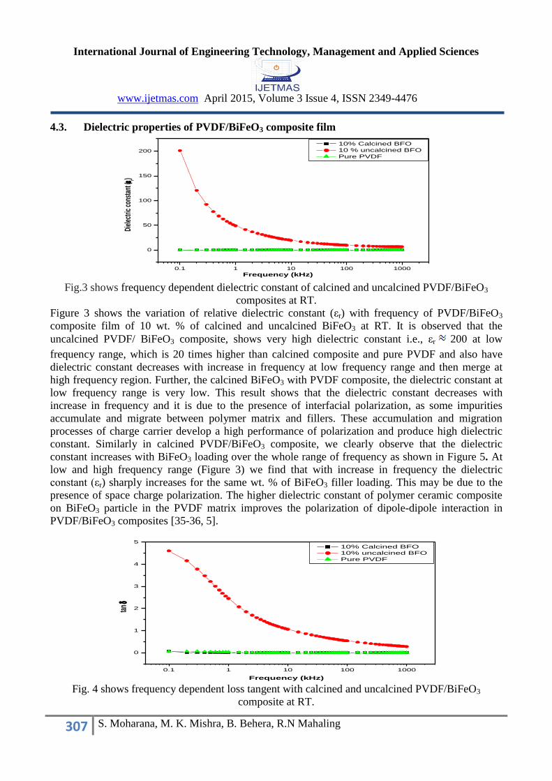
Fig.3 shows frequency dependent dielectric constant of calcined and uncalcined PVDF/BiFeO3
composites at RT.
Figure 3 shows the variation of relative dielectric constant (εr) with frequency of PVDF/BiFeO3
composite film of 10 wt. % of calcined and uncalcined BiFeO3 at RT. It is observed that the
uncalcined PVDF/ BiFeO3 composite, shows very high dielectric constant i.e., εr 200 at low
frequency range, which is 20 times higher than calcined composite and pure PVDF and also have
dielectric constant decreases with increase in frequency at low frequency range and then merge at
high frequency region. Further, the calcined BiFeO3 with PVDF composite, the dielectric constant at
low frequency range is very low. This result shows that the dielectric constant decreases with
increase in frequency and it is due to the presence of interfacial polarization, as some impurities
accumulate and migrate between polymer matrix and fillers. These accumulation and migration
processes of charge carrier develop a high performance of polarization and produce high dielectric
constant. Similarly in calcined PVDF/BiFeO3 composite, we clearly observe that the dielectric
constant increases with BiFeO3 loading over the whole range of frequency as shown in Figure 5. At
low and high frequency range (Figure 3) we find that with increase in frequency the dielectric
constant (εr) sharply increases for the same wt. % of BiFeO3 filler loading. This may be due to the
presence of space charge polarization. The higher dielectric constant of polymer ceramic composite
on BiFeO3 particle in the PVDF matrix improves the polarization of dipole-dipole interaction in
PVDF/BiFeO3 composites [35-36, 5].
0.1 1 10 100 1000
0
1
2
3
4
5
tan
Frequency (kHz)
10% Calcined BFO
10% uncalcined BFO
Pure PVDF
Fig. 4 shows frequency dependent loss tangent with calcined and uncalcined PVDF/BiFeO3
composite at RT.
International Journal of Engineering Technology, Management and Applied Sciences
www.ijetmas.com April 2015, Volume 3 Issue 4, ISSN 2349-4476
308 S. Moharana, M. K. Mishra, B. Behera, R.N Mahaling
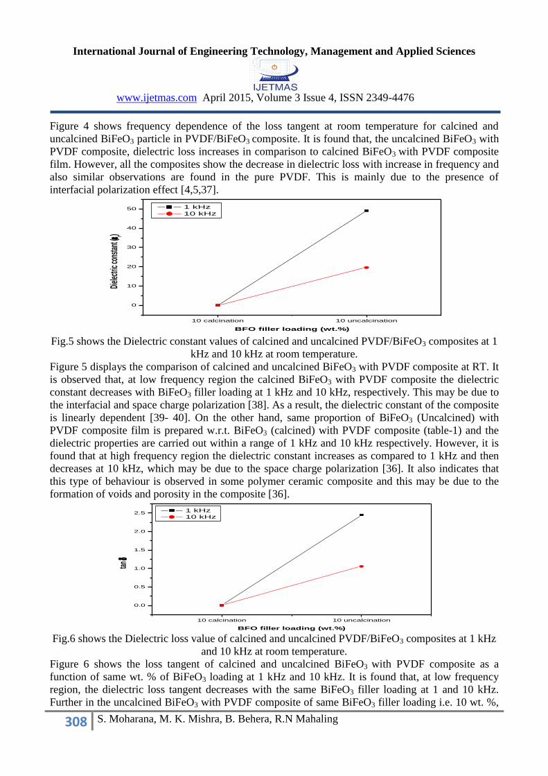
Figure 4 shows frequency dependence of the loss tangent at room temperature for calcined and
uncalcined BiFeO3 particle in PVDF/BiFeO3 composite. It is found that, the uncalcined BiFeO3 with
PVDF composite, dielectric loss increases in comparison to calcined BiFeO3 with PVDF composite
film. However, all the composites show the decrease in dielectric loss with increase in frequency and
also similar observations are found in the pure PVDF. This is mainly due to the presence of
interfacial polarization effect [4,5,37].
10 calcination 10 uncalcination
0
10
20
30
40
50
Diele
ctric
cons
tant (
r)
BFO filler loading (wt.%)
1 kHz
10 kHz
Fig.5 shows the Dielectric constant values of calcined and uncalcined PVDF/BiFeO3 composites at 1
kHz and 10 kHz at room temperature.
Figure 5 displays the comparison of calcined and uncalcined BiFeO3 with PVDF composite at RT. It
is observed that, at low frequency region the calcined BiFeO3 with PVDF composite the dielectric
constant decreases with BiFeO3 filler loading at 1 kHz and 10 kHz, respectively. This may be due to
the interfacial and space charge polarization [38]. As a result, the dielectric constant of the composite
is linearly dependent [39- 40]. On the other hand, same proportion of BiFeO3 (Uncalcined) with
PVDF composite film is prepared w.r.t. BiFeO3 (calcined) with PVDF composite (table-1) and the
dielectric properties are carried out within a range of 1 kHz and 10 kHz respectively. However, it is
found that at high frequency region the dielectric constant increases as compared to 1 kHz and then
decreases at 10 kHz, which may be due to the space charge polarization [36]. It also indicates that
this type of behaviour is observed in some polymer ceramic composite and this may be due to the
formation of voids and porosity in the composite [36].
10 calcination 10 uncalcination
0.0
0.5
1.0
1.5
2.0
2.5
tan
BFO filler loading (wt.%)
1 kHz
10 kHz
Fig.6 shows the Dielectric loss value of calcined and uncalcined PVDF/BiFeO3 composites at 1 kHz
and 10 kHz at room temperature.
Figure 6 shows the loss tangent of calcined and uncalcined BiFeO3 with PVDF composite as a
function of same wt. % of BiFeO3 loading at 1 kHz and 10 kHz. It is found that, at low frequency
region, the dielectric loss tangent decreases with the same BiFeO3 filler loading at 1 and 10 kHz.
Further in the uncalcined BiFeO3 with PVDF composite of same BiFeO3 filler loading i.e. 10 wt. %,

International Journal of Engineering Technology, Management and Applied Sciences
www.ijetmas.com April 2015, Volume 3 Issue 4, ISSN 2349-4476
309 S. Moharana, M. K. Mishra, B. Behera, R.N Mahaling
the dielectric loss tangent increases at 1 kHz and then decreases at 10 kHz which may be due to the
presence of phase inversion [36].
4.4. Impedance analysis
The complex impedance spectroscopy (CIS) [41] is an important technique which is used to
determine the electrical characteristics i.e. transport properties of bulk, grain boundary and electrode
effect of the composite material as a function of frequency. The composite material also depends on
the frequency dependent electrical parameters, which can be obtained in terms of complex dielectric
constant (ε*), complex impedance (Z*), complex modulus (M*) and loss tangent (tan δ). These
factors are co-related to each other as follows:
Complex dielectric constant (ε*) = ε'-j ε" (2)
Complex impedance (Z*) = Z'- jZ"=1/jωC0 ε* (3)
complex modulus (M*) =M'-jM"=1/ε* and tan δ= ε'/ ε" (4)
where ε' and ε" are real and imaginary parts of complex dielectric constant, Z' and Z" are real and
imaginary parts of complex impedance, M' and M" are real and imaginary parts of complex modulus,
ω=2πf is the angular frequency, C0 is the free space capacitance and j= is the imaginary part
respectively.
100 1000 10000 100000 1000000
0
1000000
2000000
3000000
4000000
5000000
6000000
0.1 1 10 100 1000
0
50000
100000
150000
200000(b)
Z' (k)
Frequency(kHz)
10% uncalcined BFO
(a)
Z'(k
)
Frequency (kHz)
10 % calcined BFO
Fig. 7 (a) and 7 (b) Variation of real parts of Z' as a function of frequency with calcined and
uncalcined PVDF/BiFeO3 composite at RT.
Figure 7a and 7b (inset) shows the variation of real (Z') with calcined and uncalcined PVDF/BiFeO3
composite as a function of frequency at RT. It is observed that both the value of Z' decreases with
rise in frequency in the low frequency region. At higher frequency region all the curves appear to
merge. It indicates the presence of space charge polarization at low frequency region but disappear in
high frequency region [42].
0.1 1 10 100 1000
0
-10000000
-20000000
-30000000
-40000000
-50000000
-60000000
-70000000
0.1 1 10 100 1000
0
-10
-20
-30
-40
-50
-60(b)
Z'' (k
)
Frequency (kHz)
10% uncalcined BFO
(a)
Z''(k)
Frequency (kHz)
10% calcined BFO
Fig. 8 (a, b) shows variation of imaginary part of impedance (Z") as a function of frequency for
calcined and uncalcined PVDF/BiFeO3 composite at RT.
International Journal of Engineering Technology, Management and Applied Sciences
www.ijetmas.com April 2015, Volume 3 Issue 4, ISSN 2349-4476
310 S. Moharana, M. K. Mishra, B. Behera, R.N Mahaling
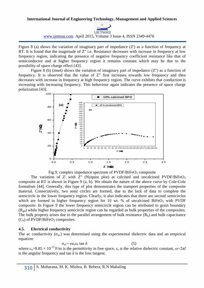
Figure 8 (a) shows the variation of imaginary part of impedance (Z') as a function of frequency at
RT. It is found that the magnitude of Z" i.e. Resistance decreases with increase in frequency at low
frequency region, indicating the presence of negative frequency coefficient resistance like that of
semiconductor and at higher frequency region it remains constant which may be due to the
possibility of space charge effect [43].
Figure 8 (b) (inset) shows the variation of imaginary part of impedance (Z") as a function of
frequency. It is observed that the value of Z" first increases towards low frequency and then
decreases with increase in frequency at high frequency region. The curve exhibits that conduction is
increasing with increasing frequency. This behaviour again indicates the presence of space charge
polarization [43].
0.0 0.5 1.0 1.5 2.0 2.5 3.0
0
-20
-40
-60
-80
-100
0 10 20 30 40 50 60 70 80 90 100110120130140150160170180190200
0
-10
-20
-30
-40
-50
-60
-70
-80
-90
-100
-110
-120
-130
-140
-150
-160
-170
-180
-190
-200
(b)
Z''
(k
)
Z' (k)
10 % uncalcined BFO(a)
Z''(
k)
Z' (k)
10% calcined BFO
Fig.9. complex impedance spectrum of PVDF/BiFeO3 composite
The variation of Z' with Z" (Nyquist plot) at calcined and uncalcined PVDF/BiFeO3
composite at RT is shown in Figure 9 (a, b). We obtain the nature of the above curve by Cole-Cole
formalism [44]. Generally, this type of plot demonstrates the transport properties of the composite
material. Consecutively, two semi circles are formed, due to the lack of data to complete the
semicircle in the lower frequency region. Clearly, it also indicates that there are second semicircles
which are formed in higher frequency region for 10 wt. % of uncalcined BiFeO3 with PVDF
composite. In Figure 9 the lower frequency semicircle region can be attributed to grain boundary
(Rgb) while higher frequency semicircle region can be regarded as bulk properties of the composites.
The bulk property arises due to the parallel arrangement of bulk resistance (Rb) and bulk capacitance
(Cb) of PVDF/BiFeO3 composites.
4.5. Electrical conductivity
The ac conductivity (ac) was determined using the experimental dielectric data and an empirical
equation:
ζac= ωεrε0 tan δ (5)
where o=8.85 × 10⁻¹²
F/m is the permittivity in free space, εr is the relative dielectric constant, ω=2πf
is the angular frequency and tan δ is the loss tangent.
International Journal of Engineering Technology, Management and Applied Sciences
www.ijetmas.com April 2015, Volume 3 Issue 4, ISSN 2349-4476
311 S. Moharana, M. K. Mishra, B. Behera, R.N Mahaling
0.1 1 10 100 1000
1E-14
1E-13
1E-12
1E-11
1E-10
1E-9
1E-8
1E-7
1E-6
1E-5
1E-4
ac(
-1m
-1)
Frequency (kHz)
10% Calcined BFO
10% uncalcined BFO
Pure PVDF
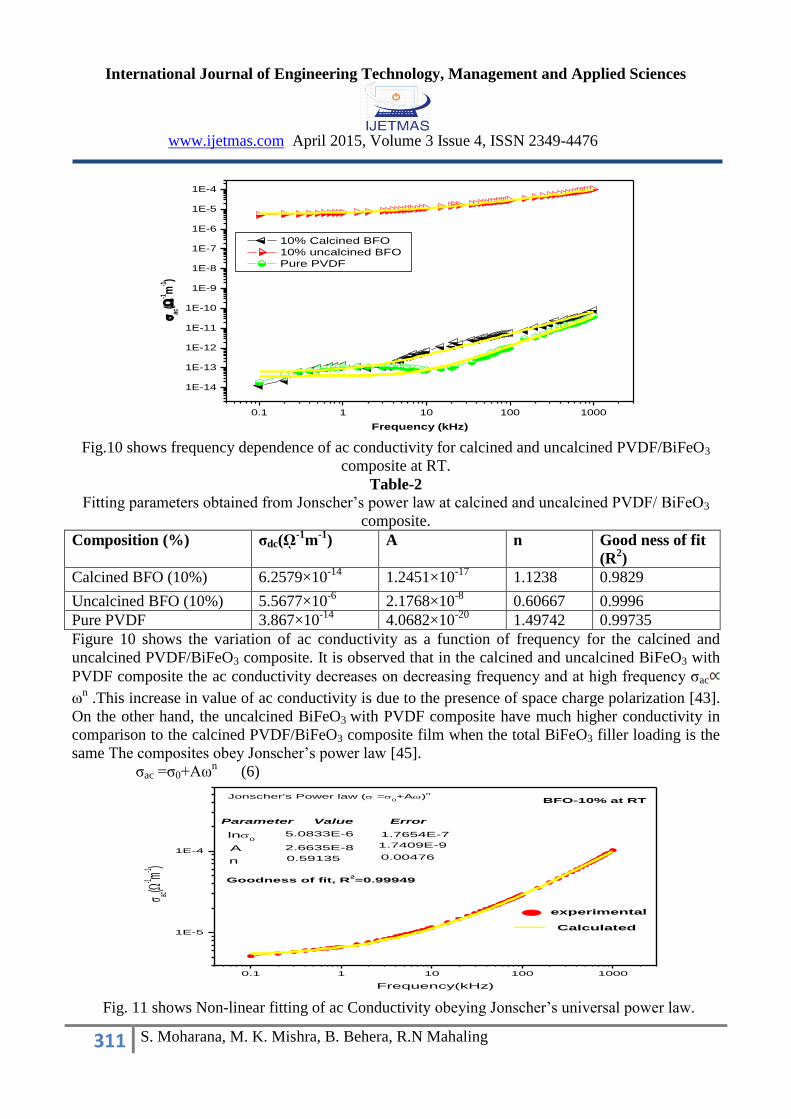
Fig.10 shows frequency dependence of ac conductivity for calcined and uncalcined PVDF/BiFeO3
composite at RT.
Table-2
Fitting parameters obtained from Jonscher’s power law at calcined and uncalcined PVDF/ BiFeO3
composite.
Composition (%) σdc(ῼ-1
m-1
) A n Good ness of fit
(R2)
Calcined BFO (10%) 6.2579×10⁻¹⁴
1.2451×10⁻¹⁷
1.1238 0.9829
Uncalcined BFO (10%) 5.5677×10⁻⁶
2.1768×10⁻⁸
0.60667 0.9996
Pure PVDF 3.867×10⁻¹⁴
4.0682×10⁻²⁰
1.49742 0.99735
Figure 10 shows the variation of ac conductivity as a function of frequency for the calcined and
uncalcined PVDF/BiFeO3 composite. It is observed that in the calcined and uncalcined BiFeO3 with
PVDF composite the ac conductivity decreases on decreasing frequency and at high frequency ζac
ωn .This increase in value of ac conductivity is due to the presence of space charge polarization [43].
On the other hand, the uncalcined BiFeO3 with PVDF composite have much higher conductivity in
comparison to the calcined PVDF/BiFeO3 composite film when the total BiFeO3 filler loading is the
same The composites obey Jonscher’s power law [45].
ζac =ζ0+Aωn (6)
0.1 1 10 100 1000
1E-5
1E-4
BFO-10% at RT
Calculated
experimental
Goodness of fit, R2=0.99949
0.00476
1.7409E-9
1.7654E-7
0.59135
2.6635E-8
5.0833E-6
n
A
ln0
Parameter Value Error
Jonscher's Power law ( =0+A)
n
ac(
-1 m-1 )
Frequency(kHz)
Fig. 11 shows Non-linear fitting of ac Conductivity obeying Jonscher’s universal power law.

International Journal of Engineering Technology, Management and Applied Sciences
www.ijetmas.com April 2015, Volume 3 Issue 4, ISSN 2349-4476
312 S. Moharana, M. K. Mishra, B. Behera, R.N Mahaling
Where ζ0 is the dc conductivity, A is the frequency dependent parameter and the value of n around 0
and 1 for the electrolyte. The detail study of ζac of PVDF/BiFeO3 composite proposed by universal
power law is obeyed.
This is confirmed by the typical fit (Table-2) of the above equation to the experimental data
shown in Figure 10 and Figure 11 respectively. According to Jonscher’s, low frequency dispersion
can be attributed to the ac conductivity whereas the frequency independent plateau regions
correspond to the dc conductivity of the composite material.
5. Conclusions
In this paper, we have synthesized two types of composite films i.e. uncalcined and calcined BiFeO3
with PVDF, which are prepared by solution casting method at RT. From X-ray diffraction pattern it
is found that calcined BiFeO3 with PVDF composite confirms the rhombohedral structure but there is
no clear diffraction peak in support of (structure of) uncalcined BiFeO3 with PVDF composite film.
In comparision, there is remarkable differences have been noticed in both the composites as per as
dielectric behaviour is concerned. For uncalcined PVDF/BiFeO3 composite the dielectric constant
(εr ) is noticed which is 20 times higher than the uncalcined one and pure PVDF. The variation
at low and high frequency region as per as the dielectric loss tangent is concerned, which is clearly
revealed from the graph this may be due to the presence of phase inversion / voids / porosity [36].
The universal Jonscher’s power law is well fit to the conductivity spectrum of both the composite
film that means conductivity can be well described by Arrhenius equation. The ac conductivity of the
composite film is in the order of 10-5
Ω-1
m-1
which is much greater than the calcined composite film
and pure PVDF.
Acknowledgement: This work is fully funded by the University Grant Commission (UGC), New
Delhi, Govt. of India, under the grant head F. No. 42 – 277/2013 (SR), UGC – MRP.
References
1. Bhadra D, Masud MDG, Sarkar S, Sannigrahi J, De SK and Chaudhuri BK. Synthesis of
PVDF/BiFeO3 Nanocomposite and Observation of Enhanced Electrical Conductivity and Low-
Loss Dielectric Permittivity at Percolation Threshold. J Polym Sc Part b: polym Phys 2012; 50:
572-579.
2 Chen Y, Zhuang Q, Liu X, Liu J, Lin S and Han Z. Preparation of thermostable PBO/graphene
nanocomposites with high dielectric constant. Nanotechnology 2013; 24: 245702-245711.
3. Kim J Y Kim, H, Kim T, Yu S, Suk JW, Jeong T, Song S, Bae MJ, Han I, Jung D and Park SH.
A chlorinated barium titanate-filled polymer composite with a high dielectric constant and its
application to electroluminescent devices. J Mater Chem C 2013; 1: 5078-5083.
4. Yang K, Huang X, Huang Y, Xie L and Jiang P. Fluoro-Polymer@BaTiO3 Hybrid Nanoparticles
Prepared via RAFT Polymerization: Toward Ferroelectric Polymer Nanocomposites with High
Dielectric Constant and Low Dielectric Loss for Energy Storage Application. Chem Mater 2013;
25(11): 2327-2338.
5. Thomas P, Satapathy S, Dwarakanath K, Varma KBR. Dielectric properties of poly (vinylidene
fluoride)/ CaCu3Ti4O12 nanocrystal composite thick films. eXPRESS Polym Lett 2010; 4 (10):
632-643.
International Journal of Engineering Technology, Management and Applied Sciences
www.ijetmas.com April 2015, Volume 3 Issue 4, ISSN 2349-4476
313 S. Moharana, M. K. Mishra, B. Behera, R.N Mahaling
6. Yu K, Wang H, Zhou Y, Bai Y, Niu Y. Enhanced dielectric properties of BaTiO3/poly
(vinylidene fluoride) nanocomposites for energy storage, applications. J. Appl Phys 2013; 113:
034105-034106.
7. Chi Q, Sun J, Zhang C, Liu G, Lin J, Wang Y, Wang X and Lei Q. Enhanced dielectric
performance of amorphous calcium copper titanate/polyimide hybrid film. J Mater Chem C
2014; 2: 172-181.
8. Verma G, Kaushik A and Ghosh AK. Preparation, characterization and properties of organoclay
reinforced polyurethane nanocomposite coatings. J. Plast Film Sheet 2012; 29(1) 56–77.
9. Sayed AME, Diab HM and Mallawany RE. Controlling the dielectric and optical properties of
PVA/PEG polymer blend via e-beam irradiation. J Polym Res 2013; 20: 1-10.
10. Xie L, Huang X, Li BW, Zhi C, Tanak T and Jiang P. Core–satellite Ag@BaTiO3
nanoassemblies for fabrication of polymer nanocomposites with high discharged energy density,
high breakdown strength and low dielectric loss. Phys Chem Chem Phys 2013; 15: 17560-
17569.
11. Dias CJ and Das-Gupta DK. Inorganic ceramic/polymer ferroelectric composite eleectrets.
IEEE Trans Dielectr Electr Insul 1996; 3(5): 706-734.
12. Bai Y, Cheng ZY, Bharti V, Xu H S and Zhang QM. High-dielectric-constant ceramic-powder
polymer composites. Appl Phys Lett 2000; 76(25): 3804-3806.
13. Das-Gupta DK and Doughty K. Polymer-ceramic composite materials with high dielectric
constant. Thin solid Films 1988; 158(1): 93-105.
14. Ayman SA and Rami AAR. Optical and Electrical Properties of Polycarbonate/MnCl2 Composite
Films. J Plast Film Sheet 2008; 24(1): 109-124.
15. Mishra SC and Aireddy H. Evaluation of dielectric behavior of bio-waste reinforced polymer
composite. J reinforc plast compos 2011; 30: 134-141.
16. Tiwari SK, Choudhary RNP and Mahapatra SP. Relaxation behavior of chlorobutyl elastomer
nanocomposites: effect of temperature, multiwalled carbon nanotube and frequency. J Polym
Res 2013; 20:1-12.
17. Shang J, Zhang Y, Yu L, Luan X, Shen B, Zhang Z, Lva F, and Chu P K. Fabrication and
enhanced dielectric properties of graphene–polyvinylidene fluoride functional hybrid films with a
polyaniline interlayer. J Mater Chem A 2013; 1: 884-890.
18. Reddy AV, Sekhar KC, Dabra N, Nautiyal A, Hundal JS, Pathak NP, Nath R. Ferroelectric and
Magnetic Properties of Hot-Pressed BiFeO3-PVDF Composite Films. ISRN Mater Sci 2011;
142968, 1-5.
19. Cheong SW and Mostovoy M. Multiferroics: a magnetic twist for ferroelectricity. Nat Mater
2007; 6 (1): 13-20.
20. Wongmaneerung R, Jantaratana P, Yimnirun R, and Ananta S. Phase Formation and Magnetic
Properties of Bismuth Ferrite–Lead Titanate Multiferroic Composites. J Supercond Nov
Magn 2013; 26 (2): 371-379.
21. Behera AK, Mohanty NK, Behera B, Nayak P. Impedance properties of 0.7(BiFeO3)-0.3
(PbTiO3) composite. Adv Mat Lett 2013; 4(2): 141-145.
22. Martins P, Costa CM, Botelho G, Lanceros-Mendez S, Barandiaran JM and Gutierrez J.
Dielectric and magnetic properties of ferrite/poly (vinylidene fluoride) Nanocomposites. J Mater
Chem Phys 2012; 131: 698-705.
23. Rosas RM, Prat JO, Juan XR Genesca MM and Rahhali A. Study on dielectric, thermal, and
mechanical properties of the ethylene vinyl acetate reinforced with ground tire rubber. J reinforc
plast compos 2011; 30: 581-592.
International Journal of Engineering Technology, Management and Applied Sciences
www.ijetmas.com April 2015, Volume 3 Issue 4, ISSN 2349-4476
314 S. Moharana, M. K. Mishra, B. Behera, R.N Mahaling
24. Spaldin NA and Fiebig M. The renaissance of magnetoelectric multiferroics. Science 2005; 309
(5733): 391-392.
25. Prellier W, Singh MP and Murugavel P. The single-phase multiferroic oxides: from bulk to thin
film. J Phys Condenced Mater 2005; 17(30): 803-832.
26. Zak AK, Gan WC, Abd.Majid WH, Darroudi M and Velayutham TS. Experimental and
theoretical dielectric studies of PVDF/PZT nanocomposite thin films, Ceramics International.
Cera Internat 2011; 22: 1057-1059.
27. Yuan JK, Dang ZM, Yao SH, Zha JW, Zhou T, Li ST and Bai J. Fabrication and dielectric
properties of advanced high permittivity polyaniline/poly(vinylidene fluoride) nanohybrid films
with high energy storage density. J Mater Chem 2010; 20: 2441-2447.
28. Dang ZM, Zha JW, Yu Y, Zhou T, Song HT and Li ST. Microstructure and Dielectric
Characterization of Micro- nanosize Co-filled Composite Films with High Dielectric
Permittivity. IEEE Trans Dielec Electr Insul 2011; 18: 1518-1525.
29. Mandal D, Kim KJ and Lee JS. Simple Synthesis of Palladium Nanoparticles, β-Phase
Formation,and the Control of Chain and Dipole Orientations in Palladium-Doped
Poly(vinylidene fluoride) Thin Films. Langmuir 2012; 28: 10310-10317.
30. Chen D, Wang M, Zhang WD and Liu T. Preparation and Characterization of Poly (vinylidene
fluoride) Nanocomposites Containing Multiwalled Carbon Nanotubes. J Appl Polym Sci 2009;
113: 644-650.
31. Dutta DP, Jayakumar OD, Tyagi AK, Girija KG, Pillaia CGS and Sharma G. Effect of doping
on the morphology and multiferroic properties of BiFeO3 nanorods. Nanoscale 2010; 2: 1149-
1154.
32. Kim JK, Kim SS and Kim WJ. Sol-gel synthesis and properties of multiferroic BiFeO3. Mater
Lett 2005; 59: 4006-4009.
33. Monshi A, Foroughi MR and Monshi MR. Modified Scherrer Equation to Estimate More
Accurately Nano-Crystallite Size Using XRD. J Nano Sci Engi 2012; 2: 154-160.
34. Behera B, Nayak P and Choudhary RNP. Structural, dielectric and electrical properties of
LiBa2X5O15 (X =Nb and Ta) ceramics. Mater Chem Phys 2006; 100: 138-141.
35. Li YC, Tjong SC and Li RKY. Dielectric properties of binary polyvinylidene fluoride/barium
titanate nanocomposites and their nanographite doped hybrids. eXPRESS Polym Lett 2011;
5(6): 526-534.
36. Li Y, Huang X, Hu Z, Jiang P, Li S and Tanaka T. Large Dielectric Constant and High Thermal
Conductivity in Poly(vinylidene fluoride)/Barium Titanate/Silicon Carbide Three-Phase
Nanocomposites. ACS Appl Mater Interfaces 2011; 3: 4396-4403.
37. Lin MF and Lee PS. Formation of PVDF-g-HEMA/BaTiO3 nanocomposites via in situ
nanoparticle synthesis for high performance capacitor applications. J Mater Chem A 2013; 1:
14455-14459.
38. Lu J, Moon KS and Wong CP. Silver/polymer nanocomposite as a high-k polymer matrix for
dielectric composites with improved dielectric performance. J Mater Chem 2008; 18: 4821-
4826.
39. Zhang X, Pint CL, Lee MH, Schubert BE, Jamshidi A, Takei K, Ko H, Gillies A, Bardhan R,
Urban JJ, Wu M, Fearing R and Javey A. Optically and Thermally-Responsive Programmable
Materials Based on Carbon Nanotube-Hydrogel Polymer Composites. Nano Letters 2011; 11:
3239-3244.
40. Dasha S, Padhee R, Das PR and Choudhary RNP. Dielectric and impedance spectroscopy of
(Bi0.5Li0.5) (Fe0.5Nb0.5) O3 multiferroics. Phase transit 2014; 87(3): 223-235.
International Journal of Engineering Technology, Management and Applied Sciences
www.ijetmas.com April 2015, Volume 3 Issue 4, ISSN 2349-4476
315 S. Moharana, M. K. Mishra, B. Behera, R.N Mahaling
41. MacDonald JR. Impedance Spectroscopy. Wiley: New York, 1987.
42. Plocharski J and Wieczoreck W. PEO based composite solid electrolyte containing nasicon.
Solid State Ionics 1988; 28: 979-982.
43. Khatri P, Behera B and Choudhary RNP. Structural and electrical properties of
Sr3V2O8ceramics. Phys Status Solidi B 2009; 246(5): 1118-1123.
44. Cole KS and Cole RH. Dispersion and absorption in dielectrics i.e., alternating current
characteristics. J Chem Phys 1941; 9: 341-351.
45. Jonscher AK. The ‘universal’ dielectric response. Nature 1977; 267: 673-679.