a 64-qam 60ghz cmos transceiver with 4-channel · pdf file20.3: a 64-qam 60ghz cmos...
TRANSCRIPT
20.3: A 64-QAM 60GHz CMOS Transceiver with 4-Channel Bonding
© 2014 IEEE International Solid-State Circuits Conference 0 of 28
Kenichi Okada, Ryo Minami, Yuuki Tsukui,
Seitaro Kawai, Yuuki Seo, Shinji Sato,
Satoshi Kondo, Tomohiro Ueno, Yasuaki Takeuchi,
Tatsuya Yamaguchi, Ahmed Musa, Rui Wu,
Masaya Miyahara, and Akira Matsuzawa
Tokyo Institute of Technology, Japan
A 64-QAM 60GHz CMOS Transceiver
with 4-Channel Bonding

20.3: A 64-QAM 60GHz CMOS Transceiver with 4-Channel Bonding
© 2014 IEEE International Solid-State Circuits Conference 1 of 28
Outline
• Motivation
• Transmitter
• Mixer-first transmitter
• Receiver
• Open-loop FVF-based amp.
• Measurement and Comparison
• Conclusion
20.3: A 64-QAM 60GHz CMOS Transceiver with 4-Channel Bonding
© 2014 IEEE International Solid-State Circuits Conference 2 of 28
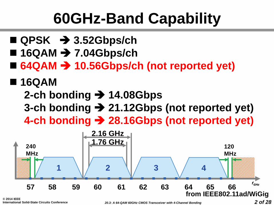
60GHz-Band Capability
QPSK 3.52Gbps/ch
16QAM 7.04Gbps/ch
64QAM 10.56Gbps/ch (not reported yet)
16QAM
2-ch bonding 14.08Gbps
3-ch bonding 21.12Gbps (not reported yet)
4-ch bonding 28.16Gbps (not reported yet)
57 58 59 60 61 62 63 64 65 66
Channel
Number
Low Freq.
(GHz)
Center Freq.
(GHz)
High Freq.
(GHz)
Nyquist BW
(GHz)
Roll-Off
Factor
A1 57.24 58.32 59.40 1.76 0.25
A2 59.40 60.48 61.56 1.76 0.25
A3 61.56 62.64 63.72 1.76 0.25
A4 63.72 64.80 65.88 1.76 0.25
Channel
Number
Low Freq.
(GHz)
Center Freq.
(GHz)
High Freq.
(GHz)
Nyquist BW
(GHz)
Roll-Off
Factor
A1 57.24 58.32 59.40 1.76 0.25
A2 59.40 60.48 61.56 1.76 0.25
A3 61.56 62.64 63.72 1.76 0.25
A4 63.72 64.80 65.88 1.76 0.25
1 2 4
240
MHz
120
MHz
1.76 GHz2.16 GHz
3
fGHz
from IEEE802.11ad/WiGig

20.3: A 64-QAM 60GHz CMOS Transceiver with 4-Channel Bonding
© 2014 IEEE International Solid-State Circuits Conference 3 of 28
Design Considerations
• Wideband gain characteristics
• RF: 57-66GHz
• BB: 1.2GHz(1ch), 5GHz(4-ch bonding)
• Wide dynamic range
• Linearity & Sensitivity
• RX SNDR >40dB
• Low phase noise (performance limiter)*
• -96dBc/Hz@1MHz (64QAM)
• I/Q mismatch & LO leakage**
• Image rejection ratio <-40dBc
*K. Okada, et al., JSSC 2013
**S. Kawai, et al., RFIC 2013
20.3: A 64-QAM 60GHz CMOS Transceiver with 4-Channel Bonding
© 2014 IEEE International Solid-State Circuits Conference 4 of 28
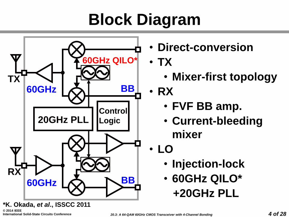
Block Diagram
• Direct-conversion
• TX
• Mixer-first topology
• RX
• FVF BB amp.
• Current-bleeding
mixer
• LO
• Injection-lock
• 60GHz QILO*
+20GHz PLL*K. Okada, et al., ISSCC 2011
TX60GHz
20GHz PLL
RX60GHz
BB
BB
Control
Logic
60GHz QILO*
20.3: A 64-QAM 60GHz CMOS Transceiver with 4-Channel Bonding
© 2014 IEEE International Solid-State Circuits Conference 5 of 28
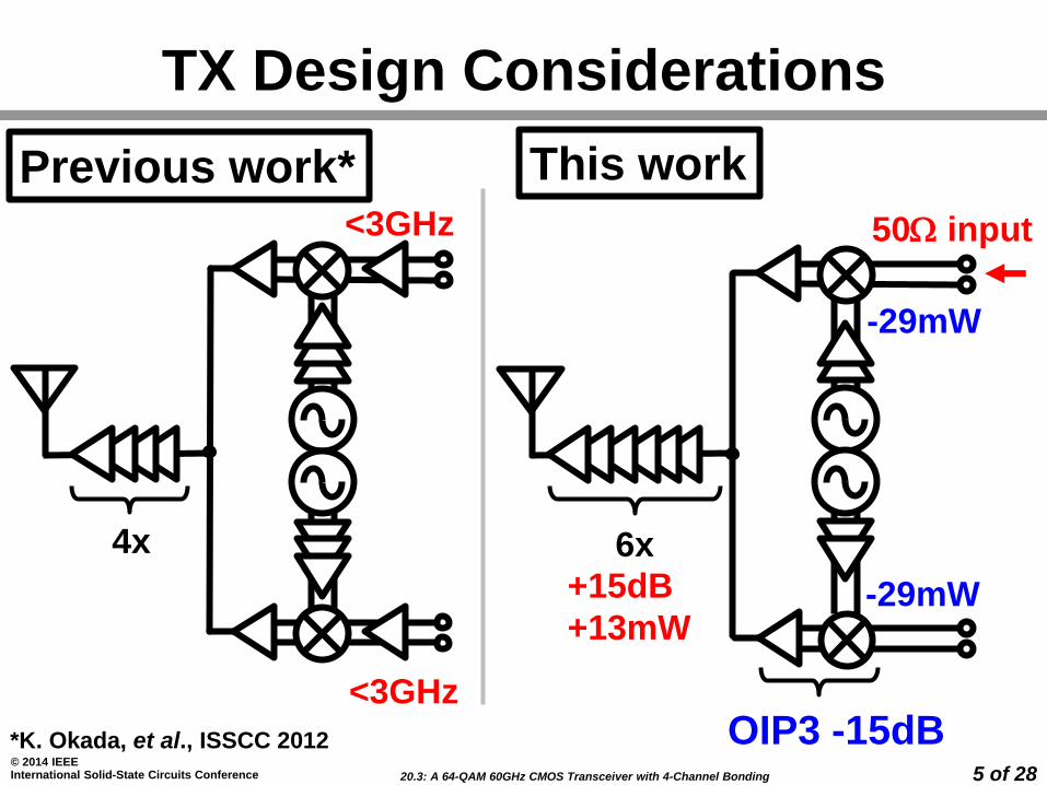
TX Design Considerations
-29mW
-29mW+15dB
+13mW
OIP3 -15dB<3GHz
<3GHz
This workPrevious work*
*K. Okada, et al., ISSCC 2012
50W input
4x 6x
20.3: A 64-QAM 60GHz CMOS Transceiver with 4-Channel Bonding
© 2014 IEEE International Solid-State Circuits Conference 6 of 28
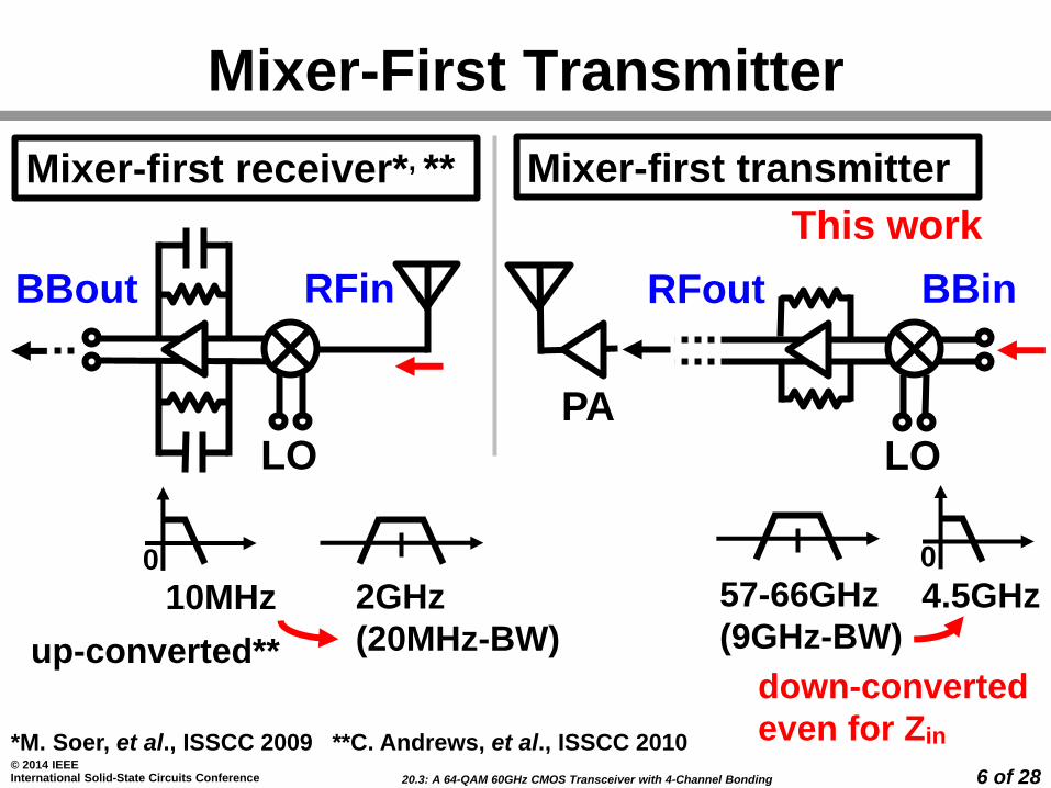
Mixer-First Transmitter
*M. Soer, et al., ISSCC 2009 **C. Andrews, et al., ISSCC 2010
RFout BBin
LO
PA
Mixer-first transmitterMixer-first receiver*, **
BBout RFin
LO
This work
10MHz 2GHz
(20MHz-BW)
4.5GHz57-66GHz
(9GHz-BW)up-converted**down-converted
even for Zin
0 0
20.3: A 64-QAM 60GHz CMOS Transceiver with 4-Channel Bonding
© 2014 IEEE International Solid-State Circuits Conference 7 of 28
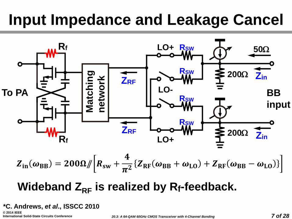
Input Impedance and Leakage Cancel
*C. Andrews, et al., ISSCC 2010
Wideband ZRF is realized by Rf-feedback.
𝒁𝐢𝐧 𝝎𝐁𝐁 = 𝟐𝟎𝟎𝛀// 𝑹𝐬𝐰 +𝟒
𝝅𝟐𝒁𝐑𝐅 𝝎𝐁𝐁 +𝝎𝐋𝐎 + 𝒁𝐑𝐅 𝝎𝐁𝐁 −𝝎𝐋𝐎
LO+
LO+
LO-
50W
To PA BB
input
200W
200W
Matc
hin
g
netw
ork
Rf
Rf
ZRF
ZRF
RSW
RSW
RSW
RSW
Zin
Zin
20.3: A 64-QAM 60GHz CMOS Transceiver with 4-Channel Bonding
© 2014 IEEE International Solid-State Circuits Conference 8 of 28
0
5
10
15
20
25
30
0.00 1.08 2.16 3.24 4.32
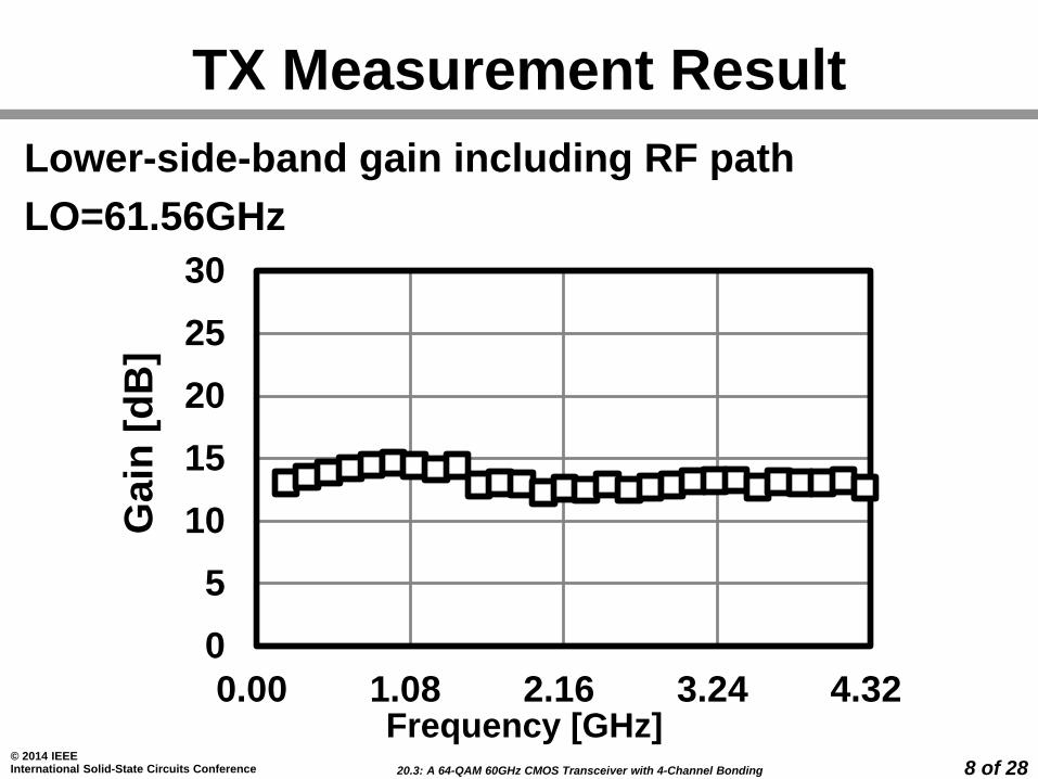
TX Measurement ResultG
ain
[d
B]
Frequency [GHz]
Lower-side-band gain including RF path
LO=61.56GHz

20.3: A 64-QAM 60GHz CMOS Transceiver with 4-Channel Bonding
© 2014 IEEE International Solid-State Circuits Conference 9 of 28
Image Rejection & LO Leakage
*S. Kawai, et al., RFIC 2013
-50
-40
-30
-20
-10
0
57.62 57.97 58.32 58.67 59.02
Frequency [GHz]
No
rma
lized
Po
wer
[dB
c]
<-47dBc-41dBc
I/Q mismatch calibration* is applied.
RF VGA & QILO phase adjustment

20.3: A 64-QAM 60GHz CMOS Transceiver with 4-Channel Bonding
© 2014 IEEE International Solid-State Circuits Conference 10 of 28
-30
-25
-20
-15
-10
0 1 2 3 4 5 6 7 8 9 10
EV
M [
dB
]
Average output power [dBm]
TX EVM Measurement
16QAMch.3 with 7.04Gb/s
20.3: A 64-QAM 60GHz CMOS Transceiver with 4-Channel Bonding
© 2014 IEEE International Solid-State Circuits Conference 11 of 28
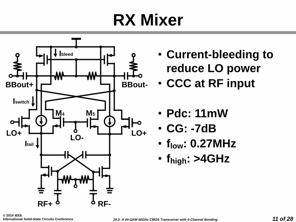
RX Mixer
• Current-bleeding to
reduce LO power
• CCC at RF input
• Pdc: 11mW
• CG: -7dB
• flow: 0.27MHz
• fhigh: >4GHz
BBout+ BBout-
RF+ RF-
Ibleed
Iswitch
Itail
M4 M5
LO-LO+ LO+

20.3: A 64-QAM 60GHz CMOS Transceiver with 4-Channel Bonding
© 2014 IEEE International Solid-State Circuits Conference 12 of 28
RX Baseband Amplifier
*R. Carvajal, et al., TCAS-I 2005
𝑨𝐕 ≅ −𝒈𝐝𝐬𝟑𝒈𝐦𝟑
• Wide bandwidth (>5GHz)
• High gain and high linearity
• Low power consumption
Flipped Voltage Follower* (FVF)
Open-loop FVF-based amplifier
vin
M3
M1
vout

20.3: A 64-QAM 60GHz CMOS Transceiver with 4-Channel Bonding
© 2014 IEEE International Solid-State Circuits Conference 13 of 28
RX Baseband Amplifier (Cont.)
−𝟏
𝒈𝐦𝟑𝑹𝐒//(1/j𝛚𝑪𝐒)−𝒈𝐦𝟕𝑹𝐋
𝑨𝐕 ≅𝒈𝐦𝟕𝒈𝐦𝟑
𝑹𝐋𝑹𝐒
𝑨𝐕 ≅ −𝟏
𝒈𝐦𝟑𝑹𝐒
modified FVF
OUT-
IN+ IN-
+ -
OUT+
M3Cs M4
Cs
M1 M2Rs Rs
M5 M6
RL RL
M9 M10
M7 M8
Vref
SleepVload
vin
M3
M1
vout Rs
by 6mW
20.3: A 64-QAM 60GHz CMOS Transceiver with 4-Channel Bonding
© 2014 IEEE International Solid-State Circuits Conference 14 of 28
Ga
in [
dB
]
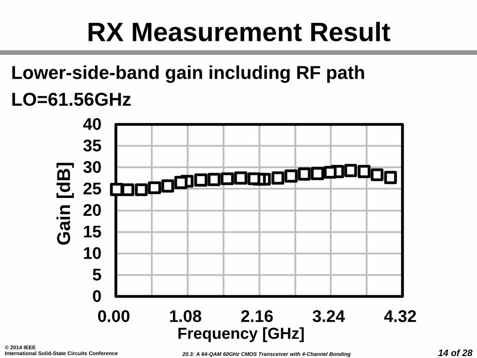
RX Measurement Result
Frequency [GHz]
0
5
10
15
20
25
30
35
40
0.00 1.08 2.16 3.24 4.32
Lower-side-band gain including RF path
LO=61.56GHz

20.3: A 64-QAM 60GHz CMOS Transceiver with 4-Channel Bonding
© 2014 IEEE International Solid-State Circuits Conference 15 of 28
60GHz LO Considerations
2ch-bond
4ch-bond
f [GHz]58.32 60.48 62.64 64.8059.40 63.7261.56
Ch.1 Ch.2 Ch.3 Ch.4
*K. Okada, et al., JSSC 2013
• -96dBc/Hz@1MHz for 64QAM
60GHz Quadrature Injection Locked Oscillator*
• Channel bonding
7 carrier frequencies
20.3: A 64-QAM 60GHz CMOS Transceiver with 4-Channel Bonding
© 2014 IEEE International Solid-State Circuits Conference 16 of 28
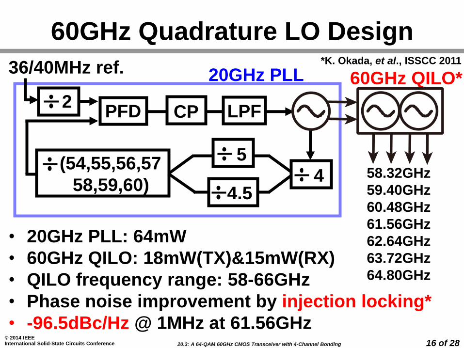
60GHz Quadrature LO Design
36/40MHz ref.
PFD CP LPF
20GHz PLL
4 (54,55,56,57
58,59,60)
2
5
4.5
60GHz QILO*
58.32GHz
59.40GHz
60.48GHz
61.56GHz
62.64GHz
63.72GHz
64.80GHz
*K. Okada, et al., ISSCC 2011
• 20GHz PLL: 64mW
• 60GHz QILO: 18mW(TX)&15mW(RX)
• QILO frequency range: 58-66GHz
• Phase noise improvement by injection locking*
• -96.5dBc/Hz @ 1MHz at 61.56GHz
20.3: A 64-QAM 60GHz CMOS Transceiver with 4-Channel Bonding
© 2014 IEEE International Solid-State Circuits Conference 17 of 28
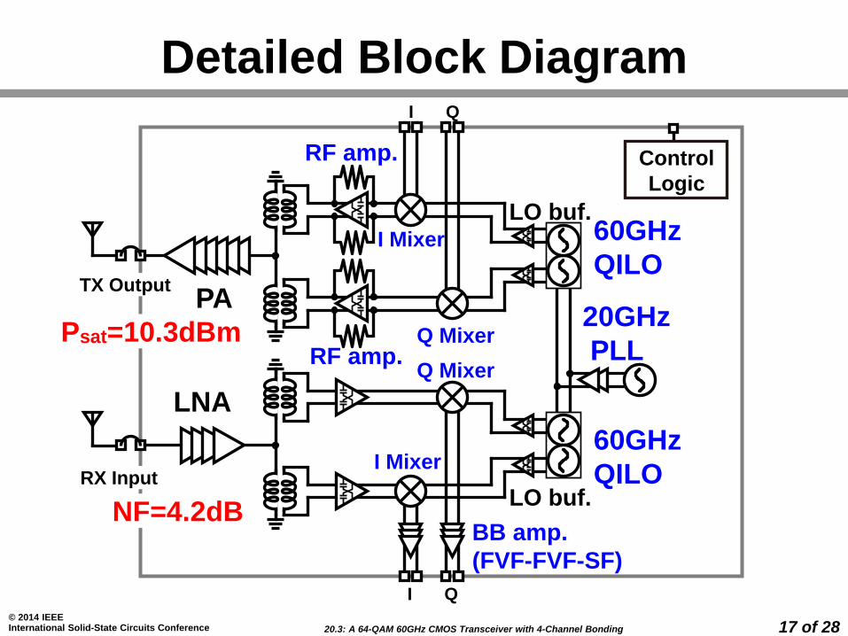
PA
60GHz
QILO
LNA
I Mixer
Q Mixer
LO buf.
RF amp.
I Mixer
Q Mixer
LO buf.60GHz
QILO
20GHz
PLL
TX Output
Control
Logic
I Q
I Q
Detailed Block Diagram
BB amp.
(FVF-FVF-SF)
RX Input
RF amp.Psat=10.3dBm
NF=4.2dB
20.3: A 64-QAM 60GHz CMOS Transceiver with 4-Channel Bonding
© 2014 IEEE International Solid-State Circuits Conference 18 of 28
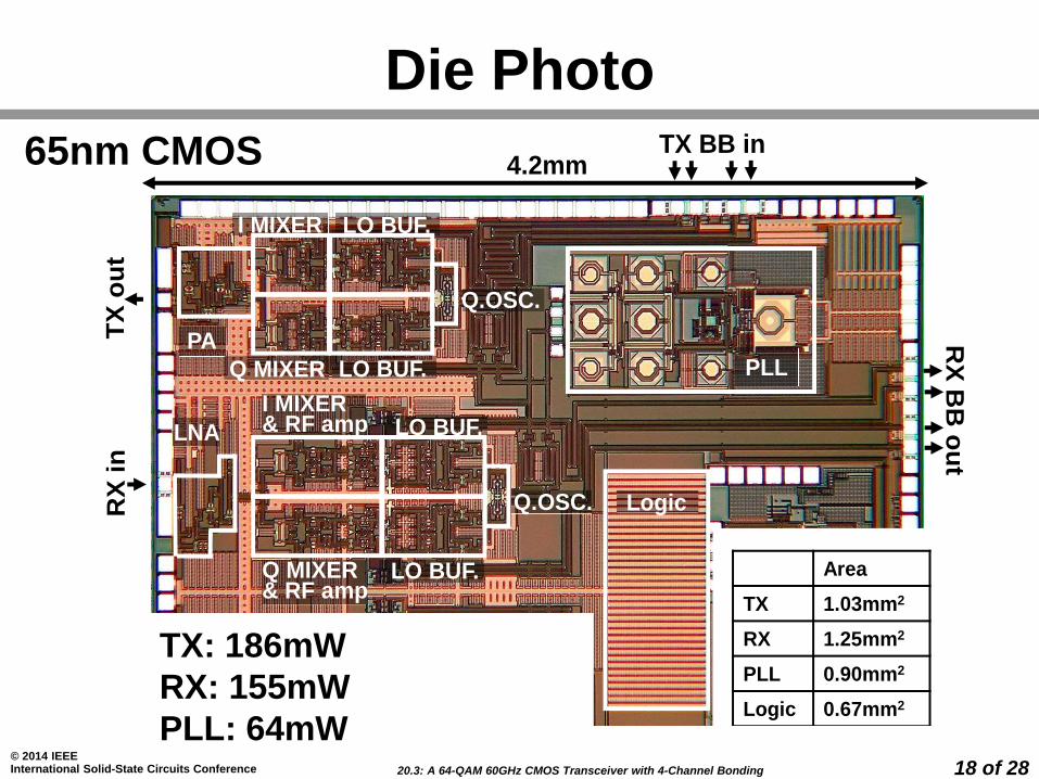
Die Photo
PA
Q MIXER
I MIXER
LO BUF.
LO BUF.
Q.OSC.
Logic
PLL
LNA
I MIXER& RF amp
LO BUF.
LO BUF.
Q.OSC.
RX
BB
ou
t
TX
ou
tR
Xin
TX BB in4.2mm
Area
TX 1.03mm2
RX 1.25mm2
PLL 0.90mm2
Logic 0.67mm2
CMOS 65nm, 1Al+11Cu
TX: 186mW
RX: 155mW
PLL: 64mW
Q MIXER& RF amp
65nm CMOS
TX: 186mW
RX: 155mW
PLL: 64mW
20.3: A 64-QAM 60GHz CMOS Transceiver with 4-Channel Bonding
© 2014 IEEE International Solid-State Circuits Conference 19 of 28
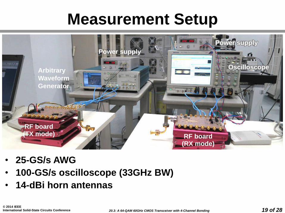
Measurement Setup
RF board(TX mode) RF board
(RX mode)
Arbitrary
Waveform
Generator
Power supply
Oscilloscope
Power supply
• 25-GS/s AWG
• 100-GS/s oscilloscope (33GHz BW)
• 14-dBi horn antennas
20.3: A 64-QAM 60GHz CMOS Transceiver with 4-Channel Bonding
© 2014 IEEE International Solid-State Circuits Conference 20 of 28
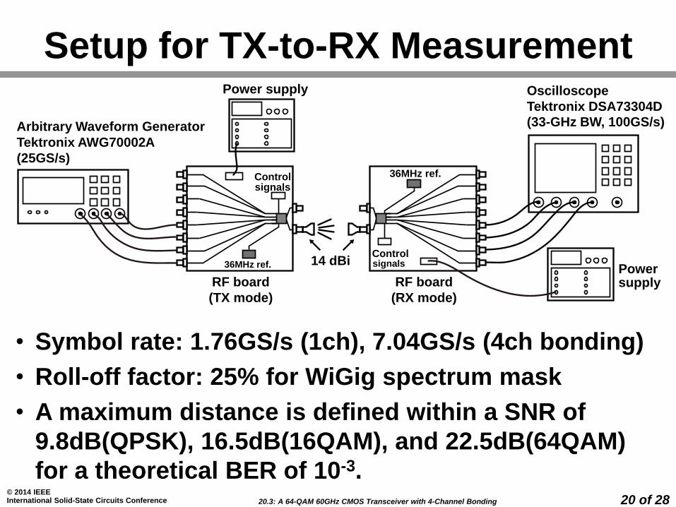
Setup for TX-to-RX Measurement
• Symbol rate: 1.76GS/s (1ch), 7.04GS/s (4ch bonding)
• Roll-off factor: 25% for WiGig spectrum mask
• A maximum distance is defined within a SNR of
9.8dB(QPSK), 16.5dB(16QAM), and 22.5dB(64QAM)
for a theoretical BER of 10-3.
RF board
(TX mode)
Oscilloscope
Tektronix DSA73304D
(33-GHz BW, 100GS/s)
RF board
(RX mode)
Powersupply
14 dBi
Power supply
Arbitrary Waveform Generator
Tektronix AWG70002A
(25GS/s)
Controlsignals
36MHz ref.Controlsignals
36MHz ref.
20.3: A 64-QAM 60GHz CMOS Transceiver with 4-Channel Bonding
© 2014 IEEE International Solid-State Circuits Conference 21 of 28
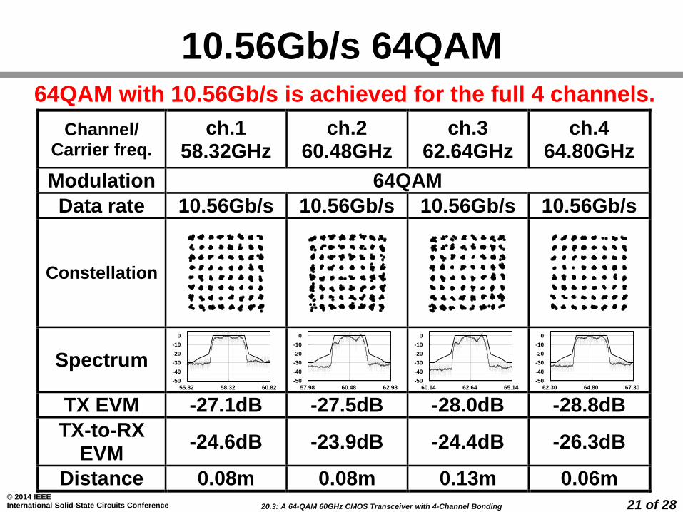
10.56Gb/s 64QAM
Channel/ Carrier freq.
ch.1 58.32GHz
ch.2 60.48GHz
ch.3 62.64GHz
ch.4 64.80GHz
Modulation 64QAM
Data rate 10.56Gb/s 10.56Gb/s 10.56Gb/s 10.56Gb/s
Constellation
Spectrum
TX EVM -27.1dB -27.5dB -28.0dB -28.8dB
TX-to-RX EVM
-24.6dB -23.9dB -24.4dB -26.3dB
Distance 0.08m 0.08m 0.13m 0.06m
-50
-40
-30
-20
-10
0
55.82 58.32 60.82
-50
-40
-30
-20
-10
0
57.98 60.48 62.98
-50
-40
-30
-20
-10
0
60.14 62.64 65.14
-50
-40
-30
-20
-10
0
62.30 64.80 67.30
64QAM with 10.56Gb/s is achieved for the full 4 channels.
20.3: A 64-QAM 60GHz CMOS Transceiver with 4-Channel Bonding
© 2014 IEEE International Solid-State Circuits Conference 22 of 28
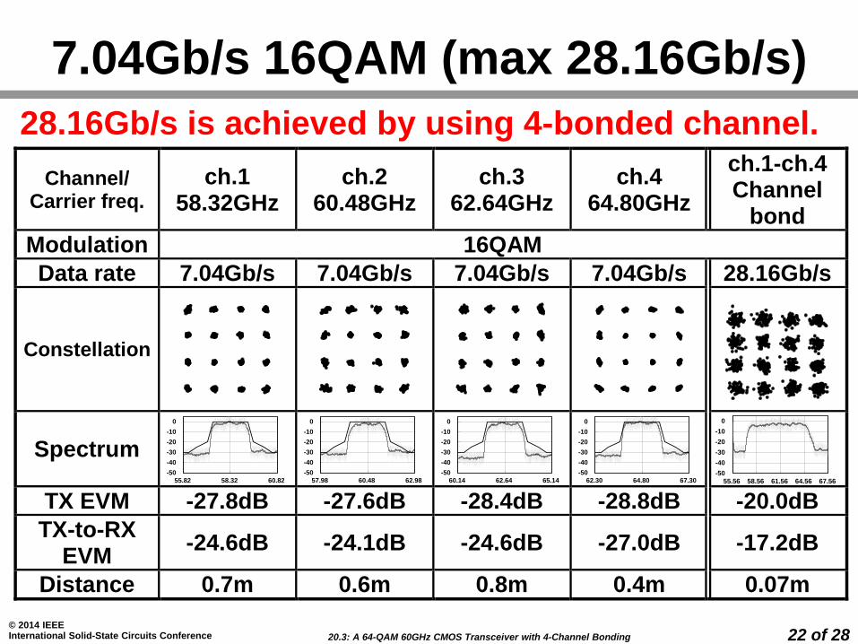
7.04Gb/s 16QAM (max 28.16Gb/s)
28.16Gb/s is achieved by using 4-bonded channel.
Channel/ Carrier freq.
ch.1 58.32GHz
ch.2 60.48GHz
ch.3 62.64GHz
ch.4 64.80GHz
ch.1-ch.4 Channel
bond
Modulation 16QAM
Data rate 7.04Gb/s 7.04Gb/s 7.04Gb/s 7.04Gb/s 28.16Gb/s
Constellation
Spectrum
TX EVM -27.8dB -27.6dB -28.4dB -28.8dB -20.0dB
TX-to-RX EVM
-24.6dB -24.1dB -24.6dB -27.0dB -17.2dB
Distance 0.7m 0.6m 0.8m 0.4m 0.07m
-50
-40
-30
-20
-10
0
55.82 58.32 60.82
-50
-40
-30
-20
-10
0
57.98 60.48 62.98
-50
-40
-30
-20
-10
0
60.14 62.64 65.14
-50
-40
-30
-20
-10
0
62.30 64.80 67.30-50
-40
-30
-20
-10
0
55.56 58.56 61.56 64.56 67.56
20.3: A 64-QAM 60GHz CMOS Transceiver with 4-Channel Bonding
© 2014 IEEE International Solid-State Circuits Conference 23 of 28
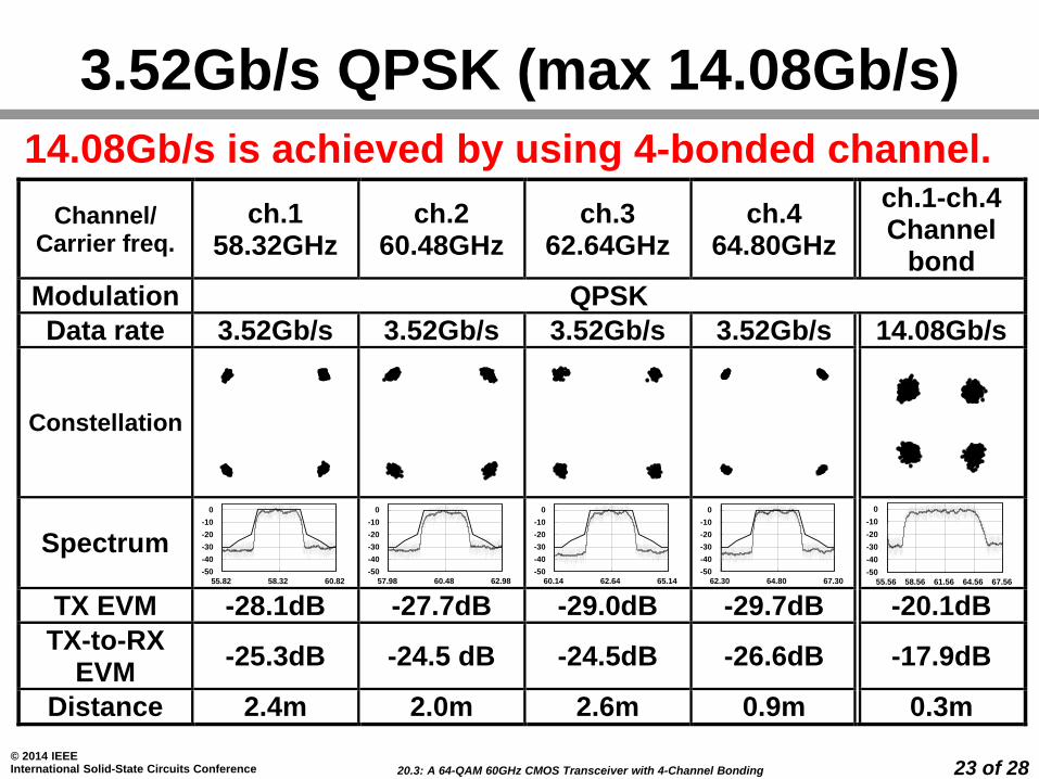
Channel/ Carrier freq.
ch.1 58.32GHz
ch.2 60.48GHz
ch.3 62.64GHz
ch.4 64.80GHz
ch.1-ch.4 Channel
bond
Modulation QPSK
Data rate 3.52Gb/s 3.52Gb/s 3.52Gb/s 3.52Gb/s 14.08Gb/s
Constellation
Spectrum
TX EVM -28.1dB -27.7dB -29.0dB -29.7dB -20.1dB
TX-to-RX EVM
-25.3dB -24.5 dB -24.5dB -26.6dB -17.9dB
Distance 2.4m 2.0m 2.6m 0.9m 0.3m
-50
-40
-30
-20
-10
0
55.82 58.32 60.82
-50
-40
-30
-20
-10
0
57.98 60.48 62.98
-50
-40
-30
-20
-10
0
60.14 62.64 65.14
-50
-40
-30
-20
-10
0
62.30 64.80 67.30-50
-40
-30
-20
-10
0
55.56 58.56 61.56 64.56 67.56
3.52Gb/s QPSK (max 14.08Gb/s)
14.08Gb/s is achieved by using 4-bonded channel.
20.3: A 64-QAM 60GHz CMOS Transceiver with 4-Channel Bonding
© 2014 IEEE International Solid-State Circuits Conference 24 of 28
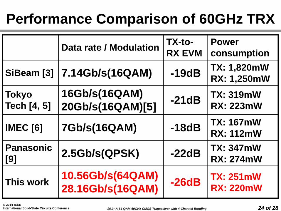
Performance Comparison of 60GHz TRX
Data rate / ModulationTX-to-
RX EVM
Power
consumption
SiBeam [3] 7.14Gb/s(16QAM) -19dBTX: 1,820mW
RX: 1,250mW
Tokyo
Tech [4, 5]
16Gb/s(16QAM)
20Gb/s(16QAM)[5] -21dB
TX: 319mW
RX: 223mW
IMEC [6] 7Gb/s(16QAM) -18dBTX: 167mW
RX: 112mW
Panasonic
[9]2.5Gb/s(QPSK) -22dB
TX: 347mW
RX: 274mW
This work10.56Gb/s(64QAM)
28.16Gb/s(16QAM)-26dB
TX: 251mW
RX: 220mW
20.3: A 64-QAM 60GHz CMOS Transceiver with 4-Channel Bonding
© 2014 IEEE International Solid-State Circuits Conference 25 of 28
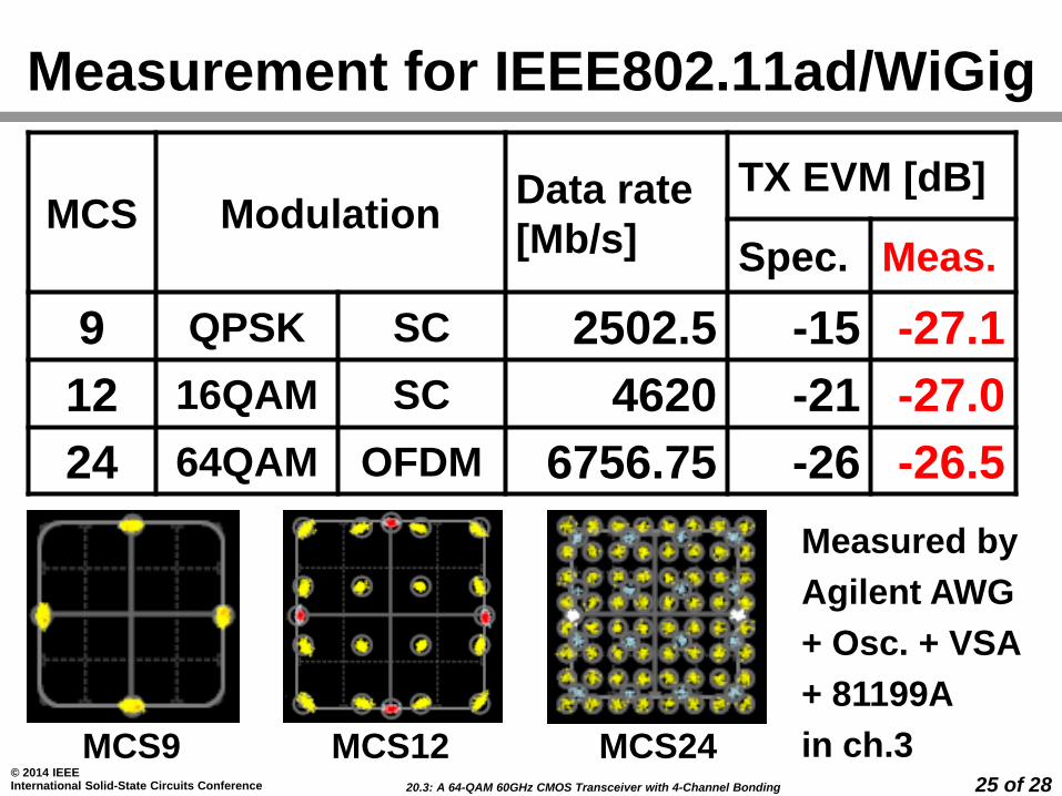
Measurement for IEEE802.11ad/WiGig
MCS ModulationData rate
[Mb/s]
TX EVM [dB]
Spec. Meas.
9 QPSK SC 2502.5 -15 -27.1
12 16QAM SC 4620 -21 -27.0
24 64QAM OFDM 6756.75 -26 -26.5
MCS9 MCS12 MCS24
Measured by
Agilent AWG
+ Osc. + VSA
+ 81199A
in ch.3
20.3: A 64-QAM 60GHz CMOS Transceiver with 4-Channel Bonding
© 2014 IEEE International Solid-State Circuits Conference 26 of 28
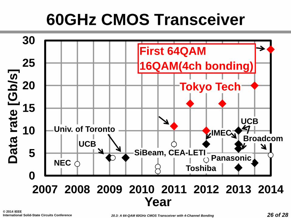
60GHz CMOS Transceiver
0
5
10
15
20
25
30
2007 2008 2009 2010 2011 2012 2013 2014
Data
ra
te [
Gb
/s]
Year
UCB
NEC
Univ. of Toronto
SiBeam, CEA-LETI
Toshiba
IMEC
Panasonic
UCB
Broadcom
First 64QAM
16QAM(4ch bonding)
Tokyo Tech
20.3: A 64-QAM 60GHz CMOS Transceiver with 4-Channel Bonding
© 2014 IEEE International Solid-State Circuits Conference 27 of 28
Conclusion
• A 60GHz direct-conversion transceiver in
65nm CMOS
• The first 64QAM transceiver (10.56Gbps/ch)
– IEEE802.11ad/WiGig conformance: MCS1-
MCS24(64QAM/OFDM)
• The first transceiver capable of 4-channel
bonding (28.16Gbps by 16QAM)
realized by
–Mixer-first transmitter
–Open-loop FVF-based baseband amplifier
–Quadrature injection-locked oscillator
20.3: A 64-QAM 60GHz CMOS Transceiver with 4-Channel Bonding
© 2014 IEEE International Solid-State Circuits Conference 28 of 28
Acknowledgement
This work was partially supported by MIC,
SCOPE, MEXT, STARC, Canon Foundation,
and VDEC in collaboration with Cadence
Design Systems, Inc., and Agilent
Technologies Japan, Ltd. The authors thank
Dr. Hirose, Dr. Suzuki, Dr. Sato, and Dr.
Kawano of Fujitsu Laboratories, Ltd., and
Prof. Ando of Tokyo Institute of Technology
for their valuable discussions and technical
supports.

20.3: A 64-QAM 60GHz CMOS Transceiver with 4-Channel Bonding
© 2014 IEEE International Solid-State Circuits Conference 29 of 28
References[1] K. Okada, et al., “A 60GHz 16QAM/8PSK/QPSK/BPSK Direct-Conversion Transceiver
for IEEE 802.15.3c,” IEEE ISSCC, pp. 160-161, Feb. 2011.
[2] A. Siligaris, et al., “A 65nm CMOS Fully Integrated Transceiver Module for 60GHz
Wireless HD Applications,” IEEE ISSCC, pp.162-163, Feb. 2011.
[3] S. Emami, et al., “A 60GHz CMOS Phased-Array Transceiver Pair for Multi-Gb/s
Wireless Communications,” IEEE ISSCC, pp.164-165, Feb. 2011.
[4] K. Okada, et al., “A Full 4-Channel 6.3Gb/s 60GHz Direct-Conversion Transceiver with
Low-Power Analog and Digital Baseband Circuitry,” IEEE ISSCC, pp. 218-219, Feb.
2012.
[5] S. Kawai, et al., “A Digitally-Calibrated 20Gb/s 60GHz Direct-Conversion Transceiver in
65-nm CMOS,” IEEE RFIC Symp., pp.137-140, June 2013.
[6] V. Vidojkovic, et al., “A Low-Power 57-to-66GHz Transceiver in 40nm LP CMOS with -
17dB EVM at 7Gb/s,” IEEE ISSCC, pp. 268-269, Feb. 2012.
[7] T. Mitomo, et al., “A 2Gb/s-Throughput CMOS Transceiver Chipset with In-Package
Antenna for 60GHz Short-Range Wireless Communication,” IEEE ISSCC, pp. 266-267,
Feb. 2012.
[8] V. Vidojkovic, et al., “ A Low-Power Radio Chipset in 40nm LP CMOS with
Beamforming for 60GHz High-Data-Rate Wireless Communication,” IEEE ISSCC, pp.
236-237, Feb. 2013.
20.3: A 64-QAM 60GHz CMOS Transceiver with 4-Channel Bonding
© 2014 IEEE International Solid-State Circuits Conference 30 of 28
References[9] T. Tsukizawa, et al., “A Fully Integrated 60GHz CMOS Transceiver Chipset Based on
WiGig/IEEE802.11ad with Built-in Self-Calibration for Mobile Applications,” IEEE
ISSCC, pp. 230-231, Feb. 2013.
[10] M. Soer, et al., "A 0.2-to-2.0GHz 65nm CMOS Receiver Without LNA Achieving
>11dBm IIP3 and <6.5dB NF," IEEE ISSCC, pp.222-223, Feb. 2009.
[11] C. Andrews, and A.C. Molnar, "A Passive-Mixer-First Receiver with Baseband-
Controlled RF Impedance Matching, < 6dB NF, and > 27dBm Wideband IIP3," IEEE
ISSCC, pp. 46-47, Feb 2010.
[12] R. Carvajal, et al., “The Flipped Voltage Follower: A Useful Cell for Low-Voltage Low-
Power Circuit Design,” IEEE Trans. CAS-I, Vol. 52, No. 7, pp. 1276-1291, July 2005.
[13] K. Okada, et al., “Full Four-Channel 6.3-Gb/s 60-GHz CMOS Transceiver with Low-
Power Analog and Digital Baseband Circuitry,” IEEE JSSC, Vol. 48, No. 1, pp.46-65,
Jan. 2013.
20.3: A 64-QAM 60GHz CMOS Transceiver with 4-Channel Bonding
© 2014 IEEE International Solid-State Circuits Conference 31 of 28
Backup slides
20.3: A 64-QAM 60GHz CMOS Transceiver with 4-Channel Bonding
© 2014 IEEE International Solid-State Circuits Conference 32 of 28
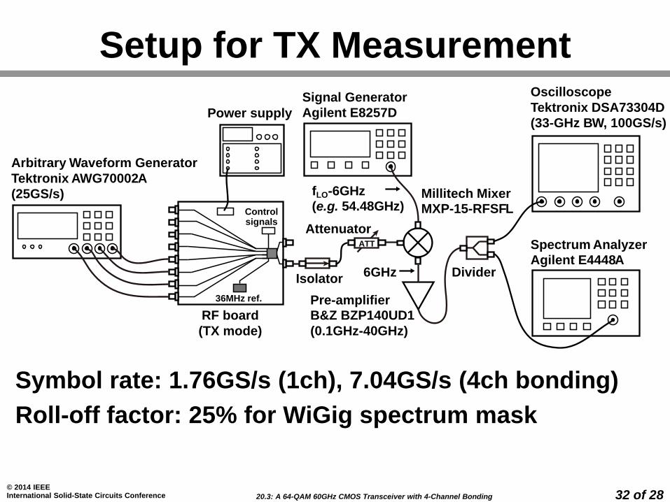
Setup for TX Measurement
Symbol rate: 1.76GS/s (1ch), 7.04GS/s (4ch bonding)
Roll-off factor: 25% for WiGig spectrum mask
RF board
(TX mode)
Power supply
Oscilloscope
Tektronix DSA73304D
(33-GHz BW, 100GS/s)
Isolator
Signal Generator
Agilent E8257D
Spectrum Analyzer
Agilent E4448A
Millitech MixerMXP-15-RFSFL
Divider6GHz
ATT
Attenuator
Pre-amplifierB&Z BZP140UD1
(0.1GHz-40GHz)
fLO-6GHz(e.g. 54.48GHz)
Arbitrary Waveform Generator
Tektronix AWG70002A
(25GS/s)
Controlsignals
36MHz ref.
20.3: A 64-QAM 60GHz CMOS Transceiver with 4-Channel Bonding
© 2014 IEEE International Solid-State Circuits Conference 33 of 28
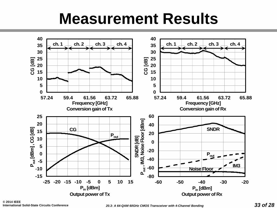
Measurement Results
-15
-10
-5
0
5
10
15
20
25
-25 -20 -15 -10 -5 0 5 10 15
Output power of Tx
Pin [dBm]
Pout[d
Bm
] , C
G [d
B]
Pout
CG
Conversion gain of Rx
Frequency [GHz]
0
5
10
15
20
25
30
35
40
57.24 59.4 61.56 63.72 65.88
CG
[d
B]
ch. 1 ch. 2 ch. 4ch. 3
-80
-60
-40
-20
0
20
40
60
-60 -50 -40 -30 -20
Output power of Rx
Pin [dBm]
SN
DR
[d
B]
Pout, I
M3, N
ois
e F
loo
r [d
Bm
]
SNDR
Pout
IM3Noise Floor
Conversion gain of Tx
Frequency [GHz]
0
5
10
15
20
25
30
35
40
57.24 59.4 61.56 63.72 65.88
CG
[d
B]
ch. 1 ch. 2 ch. 4ch. 3