8700-series home and commercial treadmill diagnostic and
TRANSCRIPT

1
111 Canfield Avenue • Randolph, New Jersey 07869 • 1-800-LANDICE • FAX 973-927-0630
8700-Series Home and Commercial Treadmill Diagnostic and Service Manual
2001
This guide covers all 8700 series treadmills manufactured from 1993 – 2000.
HOME TREADMILLS – 8700 SPRINT 1-4 / PRG / SST NOTE: Early HOME treadmills listed as: 8700R & 8700P are the same as the LTD models. The only difference was the warranty coverage. LTD / 110V UNITS – 8700R (REGILAR NO PROGRAMS) / P (WITH PROGRAMS) / PT1 / PT2 CLUB / 220V UNITS – 8700R (REGILAR NO PROGRAMS) / P (WITH PROGRAMS) / PT1 / PT2
Version M/C.1
For Technical Service Call 1-(800)-LANDICE

2
Service Manual Ver M/C.1 Page 2 Table of Contents SECTION 1- Introduction Page 3 How to use this manual Page 4-5 Landice warranty and policy Page 6 Tools needed for repairs SECTION 2- Installation Page 7-9 Safety warnings Page 10-13 Membrane panel identification SECTION 3- - Parts Identification Page 14-16 Parts listing Page 17 Commercial motor pan picture Page 18 Commercial (LTD / CLUB) motor pan lower wiring schematic Page 19-20 LED lights / SCR lower board Page 21 Home motor pan picture Page 22 Home motor pan wiring schematic Page 23 LED lights / PWM board Page 24 LED lights / RELAY board Page 25 SST, PRG, SPRINT-3 (Open Loop); lower wiring schematic Page 26 SPRINT – 2; lower wiring schematic Page 27 SPRINT – 1; lower wiring schematic Page 28 SPRINT – 1&2; upper wiring schematic SECTION 4 –Servicing Landice Treadmills Page 29-31 Definitions of components Page 32-34 Testing components Page 35-37 Common symptoms Page 38 Calibrating speed potentiometers Page 39-45 Removal and replacement of components Page 46-48 Noises Page 49 Voltage checks Page 50 Diagnostics and error codes Page 51-59 8700 LTD / CLUB diagnostic flow charts Page 60-65 8700 HOME (Closed Loop / SPRINT-4, SST, PRG) diagnostic flow charts Page 66-68 SPRINT –3 Diagnostics Page 69-75 SPRINT –2 Diagnostics Page 76-77 Tracking and Tensioning Page 78-79 Treadmill maintenance Page 80-84 Index

3
How to Use this Manual
This manual is designed to help service technicians in the installation, maintenance, or repair of
Landice 8700 model treadmills. It covers terminology, installation, tools needed, diagnostics, removal
and replacement of parts, estimated time of repairs, warranty forms, wiring schematics, and
recommended maintenance. If you find a problem not covered in this manual please call 1-800-
LANDICE to talk to a Landice Service Technician.

4
Landice Warranty and Policies PARTS Our policy requires that all defective parts be returned to Landice. All warranty parts will be billed to the dealer at dealer cost. Landice will credit this invoice upon receipt of defective parts. Landice will pay the freight to send out any defective parts. It is the dealer's responsibility to pay the freight to return the defective parts to Landice. If the defective parts are not returned within 30 days, payment of invoice is expected in full. LABOR Landice will reimburse the selling dealer according to our flat rate labor schedule. If you are a service provider for Landice and do not sell our product, you have the option of billing us direct or you can bill the dealer your providing service for. Generally, if our capped rate does not cover your labor charge you would bill the selling dealer. The current rate is $30.00 per hour and is capped at a maximum of one hour labor and one hour travel per treadmill failure. Diagnostic and return trips are not covered. Note that treadbelt tracking, treadbelt/drivebelt tensioning, blown fuses, and set-up procedures are not covered by this warranty. Set-Up Includes: Assembly, adjusting treadbelt and drive belt (if needed), walking the treadbelt and deck wax in and performing any additional adjustments that may have been upset during shipping. The dealer must call for a service authorization number prior to performing any service to verify the treadmill is under labor warranty. It is advisable to call Landice from the treadmill location to successfully diagnose the problem. This will ensure that the correct part will be shipped out the first time. Labor claim forms must be submitted within three months from the date service was performed. Labor claim forms must be completely filled out and have the Landice authorization number at the top. FLOOR MODELS The following warranty applies to floor models and dealer stock. If the dealer sells a treadmill to a customer within one year of its purchase from Landice, the warranty period will be extended to start from the date of sale to the customer. If a treadmill is over 1 year old when sold to a customer, the remainder of the parts
warranty will be honored from the date of shipment and 1 year labor.

5
September 1, 2001
Treadmill Warranty Summary
TREADMILL PARTS All defective parts must be delivered to Landice (freight prepaid) where they will either be repaired or replaced at Landice's discretion. This warranty does not cover cosmetic damage, damage due to acts of God, accident, misuse, abuse, improper maintenance, or negligence to the product. This warranty does cover normal wear and tear. This warranty is valid only in the United States and Canada. SERVICE LABOR For a period of 1 year, Landice will reimburse the selling dealer according to the terms, rates and conditions in effect at the time of service. A service authorization number must be obtained prior to performing service in order to qualify for service reimbursement. This service warranty does not cover customer instruction, installation, setup, or adjustments. Note that treadbelt tensioning and tracking is the responsibility of the user and is not covered by this warranty. Instructions for treadbelt tensioning and tracking are located in the owner's manual. This warranty is valid only in the United States and Canada.
Landice Factory Warranty Summary
Home Treadmills 07-15-1998 Lifetime Frame 5 Year Parts 1 Year Labor 07-15-1996 Lifetime Frame 3 Year Parts 1 Year Labor 07-15-1993 Lifetime Frame 2 Year Parts 1 Year Labor
8700LTD Limited Institutional Use Treadmills (120VAC)
(In applications with under 5 hours usage per day) 09-01-1996 3 Years Parts 1 Year Labor 09-01-1993 1 Year Parts 1 Year Labor
8700 CLUB Treadmills (220VAC)
(Scheduled maintenance required) 11-15-1996 3 Years Parts 1 Year Labor 11-15-1993 1 Year Parts 1 Year Labor

6
Recommended tools for servicing Landice treadmills
1. Deep socket set 3/8 drive with ratchet and extension: Must have 3/8, 7/16, 1 /2, 5/16, 9/16 socket. 2. Combination wrench set: Must have 3/8, 7/16, 1 /2, 5/16, 9/16 3. #1, 2, and 3 Philips head screwdriver (or electric screwdriver) 4. #1, 2, and 3 flat head screwdriver (or electric screwdriver) 5. Socket head cap screw wrench set/ multi Allen Wrench 6. Rubber mallet 7. Diagonal cutting pliers 8. Wire stripper 9. Wire crimping tool 10. Digital voltmeter (We recommend Radio Shack Pocket Digital Voltmeter). Analog voltmeters are
not recommended. 11. Utility knife 12. Pulse simulator

7
Important Operating Safety Instructions
WARNING: Failure to observe the following operating instructions can result in serious injury!
1 If you are suffering from any illness, condition, or disability which affects your ability to
run, walk or exercise, do not use this product without consulting your doctor first. 2 If you are suffering from any illness, condition, or disability which affects your ability to
run, walk or exercise, do not use this product without supervision present. Failure to do so can result in serious injury should you fall while the treadbelt is moving.
3 Failure to leave ample clearance around the treadmill could result in the user becoming
trapped between the treadmill and a wall, resulting in burns or other serious injury from the moving treadbelt.
Allow a minimum clearance of 18 inches on each side of the treadmill.
Allow a minimum clearance of 4 feet at the rear of the treadmill. 4 Never stand on the treadbelt when starting the treadmill. A sudden start could cause you
to lose your balance. Always stand with one foot on each side rail until the belt starts moving.
5 Always wear the emergency stop safety strap securely around your wrist while
exercising. Failure to do so can result in severe injuries should you accidentally fall while exercising.
6 Test the emergency stop safety key on a regular basis by pulling on the cord and
ensuring that the treadbelt comes to a complete stop. 7 Always remove the safety key from the treadmill when you are through exercising,
especially if children are present. This will prevent them from accidentally starting the treadmill.
8 Be sure to familiarize yourself with the owner manual. Look it over carefully. Be sure you
understand the control panel operation before using the treadmill.

8
DANGER
To reduce the risk of electric shock, always unplug the treadmill from the electrical outlet immediately after using. Always unplug the treadmill before cleaning or removing the motor cover.
WARNING
To reduce the risk of burns, fire, electric shock, or injury to persons:
1 Treadmill should never be left unattended when plugged in. Unplug from outlet when not in use.
2 Close supervision is necessary when this unit is used by or near children or disabled persons.
3 Use this treadmill only for its intended use as described in this manual. 4 Do not operate this treadmill if it has a damaged cord or plug, if it is not working properly or if it
has been damaged. Call your selling dealer immediately for examination and repair. 5 Keep the power cord away from heated surfaces. Be sure the line cord has plenty of
slack and does not get pinched underneath the treadmill when it elevates and lowers. If an extension cord must be used do not use one longer than 6 feet with 12 gauge wire.
6 Never operate the treadmill with the air openings blocked. Keep the air openings free of lint, hair, and the like.
7 Never drop or insert any object into any opening. Be sure no objects are near or underneath the moving treadbelt when using the treadmill.
8 Do not use outdoors. 9 Do not operate where aerosol spray products are being used or where oxygen is being
administered. 10 Connect this appliance to a properly grounded outlet only. Do not use a GFI outlet. 11 To disconnect, press the OFF button, remove the SAFETY LANYARD, and unplug the
unit from the wall outlet.
GROUNDING INSTRUCTIONS This product must be grounded. If it should malfunction or break down, grounding provides a path of least resistance for electric current to reduce risk of electric shock. This product is equipped with a cord having an equipment-grounding conductor and a grounding plug. The plug must be plugged into an outlet that is properly installed and grounded in accordance with all local codes and ordinances. We do not recommend using a GFI outlet.
120 Volt Treadmills (15 Amp dedicated line) Treadmills marked 120 VAC are intended for use in a nominal 120-volt circuit with a grounding plug. Make sure the product is connected to an outlet having the same configuration as the plug. No adapter should be used with this product.

9
200 - 250 Volt Treadmills (15 Amp dedicated line) Treadmills marked 200-250 VAC are intended for use on a circuit having a nominal rating more than 120V and are factory-equipped with a specific cord and plug to permit connection to a proper electric circuit. Make sure the product is connected to an outlet having the same configuration as the plug. No adapter should be used with this product. If the product must be reconnected for use on a different type of electric circuit, the reconnection should be made by qualified service personnel. DANGER! Improper connection of the equipment-grounding connector can result in a risk of electric shock. Check with a qualified electrician or serviceman if you are in doubt as to whether the product is properly grounded. Do not modify the plug provided with the product. If it will not fit in the outlet, have a proper outlet installed by a qualified electrician.

10
8700 Standard Membrane
Models That Used This Membrane: 8700, 8700-R, 8700-LTD, 8700-LTD-VFX, 8700-CLUB, 8700-CLUB-VFX
Production Time Frame: 1991-1999 Electronics: Standard 110V SCR (220V SCR for CLUB units), commercial motor pan.
See Wiring Diagram. Settings Used In: Home and Commercial (LTD’s and CLUB’s)
Key Features: Closed Loop Treadmill (w/ speed sensor), Safety Lanyard, 0.5-11MPH Push Button Speed and Elevation Control
8700 Sprint Membrane
Models That Used This Membrane: 8700 Sprint-1, 8700 Sprint-2 Production Time Frame: Sprint-1 1991-1995, Sprint-2 1995-1996
Electronics: 110V Unit, See Wiring Diagrams for 8700 Sprint-1 and Sprint-2 Settings Used In: Home
Key Features: Open Loop Treadmill (w/o speed sensor), Safety Lanyard on Sprint-2 only, 1.0-9.0MPH Rheostat Speed Control, Rocker Switch Elevation Control.

11
8700 EP/PT Membrane
Models That Used This Membrane: 8700EP, 8700-PT Production Time Frame: 1991-1993
Electronics: Standard 110V SCR (220V SCR for CLUB units), commercial motor pan. See Wiring Diagram.
Settings Used In: Home and Commercial Key Features: Closed Loop Treadmill (w/ Speed sensor) Safety Lanyard, 0.5-11.0MPH Push Button Speed and Elevation Control, 10 Built In Programs, 4 User Programs, Wireless Heart Rate Control
(Optional), LED Graphic Display.
8700 P Membrane
Models That Used This Membrane: 8700-P, 8700-LTD-P, 8700-CLUB-P Production Time Frame: 1991-1999
Electronics: Standard 110V SCR (220V SCR for CLUB units), commercial motor pan. See Wiring Diagram.
Settings Used In: Home and Commercial (LTD’s and CLUB’s) Key Features: Closed Loop Treadmill (w/ speed sensor), Safety Lanyard, 0.5-11MPH Push Button
Speed and Elevation Control, 5 Built In Programs.

12
8700 PT2 Membrane
Models That Used This Membrane: 8700-PT2, 8700-CLUB-PT2 Production Time Frame: 1994-1998
Electronics: Standard 110V SCR (220V SCR for CLUB units), commercial motor pan. See Wiring Diagram.
Settings Used In: Home and Commercial Key Features: Closed Loop Treadmill (w/ Speed sensor) Safety Lanyard, 0.5-11.0MPH Push Button
Speed and Elevation Control, 9 Built In Programs, 4 User Programs, Wireless Heart Rate Control, SONAR ranging capability (Optional), LED Graphic Display.
8700 SST Membrane
Models That Used This Membrane: 8700-SST, 8700-SST-VFX Production Time Frame: 1995-1999
Electronics: 8700-SST used Sprint-3 electronics, 8700-SST-VFX used Sprint-4 electronics, See Wiring Diagrams.
Settings Used In: Home Key Features: 8700-SST Open Loop Treadmill (w/o speed sensor), 8700-SST-VFX Closed Loop
Treadmill (w/ Speed sensor) Safety Lanyard, 0.5-12.0MPH Push Button Speed and Elevation Control. 5 Built In Programs, 5 User Programs, Wireless Heart Rate Control, SONAR ranging capability.

13
8700 Programmable Membrane
Models That Used This Membrane: 8700-PRG, 8700-PRG-VFX, 8700-CLUB-PRG Production Time Frame: 1996-1999
Electronics: 8700-PRG used Sprint-3 electronics, 8700-PRG-VFX used Sprint-4 electronics, 8700-CLUB-PRG used 220V PWM commercial motor pan. See Wiring Diagrams.
Settings Used In: Home and Commercial (LTD’s and CLUB’s) Key Features: Closed Loop Treadmill (w/ speed sensor), Safety Lanyard, 0.5-12MPH Push Button
Speed and Elevation Control, 4 Built In Programs, 2 User Programs.
8700 Sprint Faceplate
Models That Used This Faceplate: 8700 Sprint-3, 8700 Sprint-4, 8700-Sprint-4-VFX Production Time Frame: Sprint-3 1997-1998, Sprint-4 1998-1999
Electronics: 110V Unit, See Wiring Diagrams for 8700 Sprint-3 and Sprint-4 Settings Used In: Home
Key Features: Sprint-3 Open Loop Treadmill (w/o speed sensor), Sprint-4 Closed Loop Treadmill (w/ Speed sensor) Safety Lanyard, 0.5-12.0MPH Push Button Speed and Elevation Control.

14 Section 3 – Parts Identification
Item Part# MSRP NoteTreadbelt 70046 $326.00Treadbelt - XL 70157 $381.00Slider Deck (Non-VFX) 70033 $208.75Slider Deck - XL (Non-VFX) 70156 $258.35VFX Deck 70218 $200.00VFX Deck Spacer 70219 $9.00 2 per treadVFX Deck Slat 70215 $25.05 3 per treadVFX Deck Post 70216 $5.00 6 per treadVFX Deck Load Washer 70217 $3.40 6 per treadVFX Deck, Flet Washer 70220 $2.50 6 per treadVFX Deck, Impact Adjuster 70221 $0.20 6 per treadDrive Motor, 3 HP, 110V 70014 $584.50 must order w/ 70010Flywheel 70010 $75.15Motor Bracket 70043 $59.70Tension Screw 70071 $2.50Metal Spacer 70089 $1.89 3 per treadRubber Spacer 70090 $1.65 2 per treadHitch Pin 233 $0.42 2 per treadDrive Belt 220J10 $25.05Motor Brush, 110V 70222 $15.53 2 per treadMotor Brush Holder misc $58.16Motor Brush Cap misc $7.11Foam Block 70103 $8.35Elevation Assembly 70027 $181.02Elevation Motor, 110V 70088 $275.00Elevation Potentiometer 71013 $32.72Elevation Pins 70032 $2.83 2 per treadElevation Nut MISC $25.05Elevation Clevis 70049 $17.28Bearing Block 70034 $14.00Pan 70048 $150.00PWM 110V KBWT-110 $280.50RELAY Board, PWM 70213 $100.50Nylon Spacer, # 8 Screw 71035 $0.25Reading Rack Clear 71018 $35.00Display Board - 8700PRG (Closed Loop) 70196-CL $518.00Display Board - 8700SST (Closed Loop) 70173-CL $541.08Display Board - SPRINT4 (Closed Loop) 70191-CL $275.00Display Board - SPRINT - Metric 70191-Metric $285.00Display Board - SPRINT -7 Mph 70191-RTM $285.00SONAR Transducer W/ cable 70179 $60.15SONAR Ranging Board 70178 $100.20SONAR Hardware 70177 $8.75
Model 8700 Treadmill Parts

15
Membrane Panel - SPRINT3/4 70190 $167.00Membrane Panel - 8700PRG 70195 $225.45Membrane Panel - SST 70171 $225.45Membrane Panel - NMA (CRT,PRT) 70191-NMA $210.42Velcro Circle 70096 $0.85Velcro Strip 70095 $5.00Drive Roller Assembly 70036 $215.75 must order w/ CV-18-2Sheave, Frt Roller CV-18-2 $20.04Take Up Roller Assembly 70039 $200.40DC Transformer, 9V 110V 5302 $24.63Control Panel Frame 70018 $114.90Control Panel W/ Sonar Hole 70018-S $116.90Bracket Sonar 70172 $5.00Upright, Left 70020 $116.57Upright, Right 70019 $116.57Stablizer Plate 70210 $25.00Control Panel End Cap, Right 70061 $8.52Control Panel End Cap , Left 70062 $8.52Frame Rail , Left 70016 $215.17Frame Rail, Right 70015 $215.17Decal, Frame, Right 70055 $22.45Decale, Frame, Left 70056 $22.45Side FrameTop Cover 70017 $51.35Harness, SPRINT4 Upper 70211 $30.00Harness, SPRINT4 Lower 70212 $15.05Isolation Transformer 70202 $429.50Supression kit MISC $17.00Axi Shock Supension FOOT 71029 $60.00 Right or LeftFoot Clamp (Solid foot) 70008 $15.00Motor Cover Grey 70044 $158.65 must order w/70209 (no charge)8700 Landice name plate 70209 $8.25Motor Cover , Fire Retardant Black 70044-FR $242.15Motor Cover, Clear 70044-CLEAR $317.308-32 x 3/4 PPHTT BL OX 8-32_3/4_TTB $0.75 screw for motor coverSpeed Sensor 71007 $58.50Speed Sensor Bracket 70067 $3.76Line Cord, with 5-15P Plug 5211 $48.26Plug, 5-15P, Hospital Grade (110V) 5-15PHGP $33.00Strain Relief 1250 $0.58Fuse, 110V MDA-20 $2.51Fuse Holder MDA-HOLDER $3.25

16
Wireless Pulse Option "Pulse Kit" 71017 $167.00Extender Kit MISC $25.05Receiver Kit 70074/MISC $125.25Pulse Belt/Transmitter 70072/70073 $108.55Pulse Receiver 70074 $100.20Extender Cable 71009 $16.70Right Angle Adapter 71010 $8.35Isolation Leakage Option MISC $167.00Isolation Leakage Option Dealer Installed MISC $20.00Traction Strip 70005 $11.41Cover, Side Frame 70017 $51.35SIDE FRAME XL $190.00Side Rail 70052 $53.44Rail Clamp 70021 $33.57Cross Bar 70051 $25.05 must order w/1858Cross Bar Foam 1858 $7.55Hardware Kit 71020 $25.05Medical Rail 70135 $104.38 must order w/70185Foam Medical & Runners Rail 70185 $8.35Installation Charge, Optional Rails MISC $108.55Spacer, Rail Support 70006 $5.01End Cap 70045 $12.53Wheel 4851 $6.68 2 per treadNMA Sticker 70188 $1.67Safety Lanyard 71011 $15.508700SPRINT User's Manual 72008 $8.358700PRG User's Manual 72012 $8.358700SST User's Manual 72011 $8.35Institutional Brochures 70199Home Brochures 70200Quality Construction Manual 72017Touch Up Paint 70224 $25.05Slipcote Lubricant 1oz Packet 71037 $1.50Slipcote Lubricant QUART 71030 $35.00 4 cans/save$4.00Slipcote Lubricant GALLON 71031 $96.00 16cans/save$39.00Applicator 71016 $4.00

17
8700 COMERCIAL MOTOR PAN COMPONENTS

18
8700 COMMERCIAL LOWER WIRING SCHEMATIC

19
LED (light emitting diode) configurations: SCR lower board The SCR lower board is designed with diagnostic LED lights. The LED’s are color coded according to their specific function. Green indicates a properly operating treadmill; the green lights should always be ON when power is supplied to the treadmill. Yellow indicates a treadmill function. Red indicates a treadmill malfunction. Here is a list of each LED and what it signifies: MOTOR (yellow) – The MOTOR LED illuminates when dc (direct current) voltage is sent to the drive motor. The LED gets brighter when the dc output is increased. RLC (yellow) – The RLC (R = Reactance / L = Inductance / C = Capacitance) LED illuminates when the filtering system is properly working. The filtering system includes the capacitor and filter choke. If there is a short in either component then the RLC light will not come on. DN & UP (yellow) – The DN and UP LED lights tell us if the elevation DN and UP relays are functioning properly. When the LED lights, it tells us that the relay has energized and is sending high voltage (110vac or 220vac) to the elevation motor. AC PWR (green) – The AC PWR (Alternating Current Power) illuminates when AC line voltage is delivered to the treadmill. It then passes through the in-line fuse (110)/s(220) and lights the AC PWR LED. +12V (green) – When the proper AC voltage is delivered to the treadmill, passes through the in-line fuse/s, through the full wave bridge rectifier (changes AC to DC), through the transformer (steps down DC to +12vdc) then the +12V LED lights.

20 C. LIM (red) – The C.LIM or Current Limit LED should NEVER come on. This diagnostic light is used to determine the condition of the treadbelt and deck. The SCR board has a built-in amp meter. When the treadbelt belt and deck system wears, the amperage will increase. When this amperage reaches its max limit, the lower board will shut down its power (treadbelt will slow down / low torque) to the drive motor and the C.LIM LED will illuminate. SPD (yellow) – The SPD LED flashes on and off (relative to speed) when the speed sensor is operating properly. GRD (red) – The GRD LED should NEVER come on. It illuminates only when the elevation potentiometer becomes out of calibration. SERIAL (red) – The SERIAL LED should NEVER come on. It illuminates only when there is a serial error. This could be a loose or pushed pin on the main wire harness. +5V (green) – The +5V light comes on when there is power going to the Upper Display. If the light is not on check wire harness for connections. If it ‘s not the wire harness then the MCB is defective.

21
8700 HOME SST VFX, PRG VFX, SPRINT VFX CLOSED LOOP (SPEED SENSOR)

228700 SST, PRG and SPRINT VFX TREADMILL
All VFX treadmills utilize CLOSED LOOP speed control. All treadmills listed as VFX in the warranty database use a speed sensor.

23
LED LIGHTS ON PWM The PWM lower board is designed with two diagnostic LED lights. The LED’s are color coded according to their specific function. LED 1 (red) – This indicates a high current draw similar to the C.LIM LED on our SCR lower control board. LED 1 will only light if there is high current being used due to a possible worn out treadbelt and deck system or it can also light if the IR pot is out of adjustment. The IR pot controls how the PWM board reacts to varying loads (users’ weights). If the IR pot is out of adjustment you will notice the treadbelt will surge and the red LED 1 will flash in unison with the belt surge. LED 2 (green) – This indicates proper line voltage is being supplied to the PWM board. This line voltage is delivered to the PWM via the belt relay located on the relay board. When the belt relay energizes 110VAC or 220VAC is sent to the input terminals (L1 & L2) on the PWM board and LED 1 illuminates.

24
LED (light emitting diode) configurations: RELAY BOARD
The RELAY board is designed with diagnostic LED lights. The LED’s are color coded according to their specific function. Green indicates a properly operating treadmill; the green lights should always be ON when power is supplied to the treadmill. Yellow indicates a treadmill function. Red indicates a treadmill malfunction. Here is a list of each LED and what it signifies: AC PWR (green) - The AC PWR (Alternating Current Power) illuminates when AC line voltage is delivered to the treadmill. It then passes through the in-line fuse (110)/s(220) and lights the AC PWR LED. VDC (green) – The VDC LED will light when it receives DC voltage from the DC power supply. DN & UP (yellow) – The DN and UP LED lights tell us if the elevation DN and UP relays are functioning properly. When the LED lights, it tells us that the relay has energized and is sending high voltage (110vac or 220vac) to the elevation motor. UPSW (green) – This LED will illuminate when the low voltage dc is delivered from the upper display board to the elevation UP relay. This low voltage dc is what energizes the coil of the relay. DNSW (green) - This LED will illuminate when the low voltage dc is delivered from the upper display board to the elevation DOWN relay. This low voltage dc is what energizes the coil of the relay. BELTSW (green) - This LED will illuminate when the low voltage dc is delivered from the upper display board to the belt (motor start) relay. This low voltage dc is what energizes the coil of the relay. SPD (yellow) – The SPD LED flashes on and off (relative to speed) when the speed sensor is operating properly. PWM (yellow) – This LED will light when the upper board is sending a speed signal to the PWM. Both the PWM LED and BELTSW LED must be lit for belt movement.
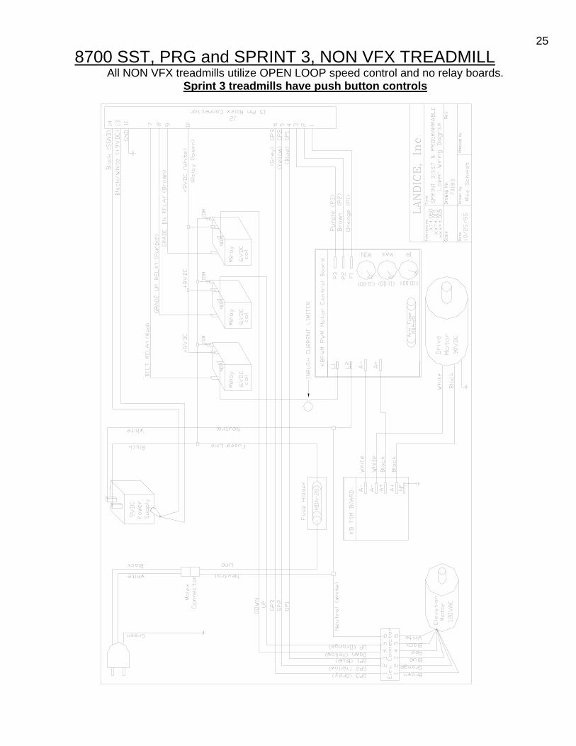
258700 SST, PRG and SPRINT 3, NON VFX TREADMILL
All NON VFX treadmills utilize OPEN LOOP speed control and no relay boards. Sprint 3 treadmills have push button controls

268700 SPRINT 2
Safety lanyard, speed control dial (not push button), KBWT-110 SCR motor control

278700 SPRINT 1 – LOWER WIRING SCHEMATIC
NO safety key, speed control dial (not push button), KBLC-118 Motor Control Board

28
8700 SPRINT 1&2 UPPER WIRING SCHEMATIC

29Section 4- Servicing Landice Treadmills
Definitions
12 VDC POWER SUPPLY (Transformer) This transformer converts AC power to DC power. It provides low voltage current for the upper display board. This component is found on treadmills with PWM motor control boards. It is incorporated into the SCR motor control boards. CAPACITOR Stores energy to smooth out voltage to drive motor. Used with SCR motor control boards. CHOKE (Inductor) Acts like a filter to smooth out voltage to drive motor. Used with SCR motor control boards. DECK Wooden board 1” thick with a phenolic coating. Treadbelt rides over it. It is reversible. DRIVE BELT This connects drive motor to sheave (pulley) on drive roller. DRIVE MOTOR Provides power to drive belt to turn pulley on drive roller to move treadbelt. This gets its power from the PWM or SCR. Landice drive motors are either 110v for 220v. DRIVE ROLLER W/ SHEAVE This is the roller at the front of the treadmill. The sheave (pulley) is pressed onto the roller and allows transfer of movement from drive belt to treadbelt. ELEVATION LEG ASSEMBLY Connects to elevation motor to allow movement of front of treadmill up or down. ELEVATION MOTOR This motor works through the elevation leg assembly to raise or lower the front of the treadmill. It gets its power from the relay board on home models and from the SCR on LTD and CLUB models. ELEVATION POTENTIOMETER Attaches to elevation motor and gives feedback to upper display as to what incline the treadmill is at. Needs to be calibrated whenever elevation motor is replaced. A potentiometer should be checked whenever there is a problem with elevation or when error code PO comes up. FACE PLATE This overlay is found on our Sports Trainer, Pro Sports Trainer, and CRT models and is screwed onto the Upper Display Board. SIDE FRAMES One on either side, these connect with the Deck Slats and Motor Pan to form the frame of the machine.

30SIDE FRAME COVERS These sit on top of the frame rails and keep deck in place. They also form the base for the traction strip. IR POTENTIOMETER The IR Pot is located on the PWM motor control board and is used to adjust the time it takes the PWM to react to a load or amperage spike. It normally requires adjustment if the motor feels like its surging. MEMBRANE PANEL This takes information from the display membrane keys and transmits it to upper display board via the ribbon cable. It is found on the PT, CT, and ET models. PWM (Pulse Width Modulation) Motor Control Boards- Used in home models. This circuit board is designed to run the drive motor. It takes the AC voltage from the wall outlet and changes it to DC voltage to run the drive motor. The AC voltage comes in on the L1 line and L2 line terminals on the PWM where it’s rectified (change from AC to DC) and comes out as DC on terminals A+ and A- (Armature + and Armature -). Since the PWM motor control switches at such a high frequency, the DC voltage produced is “clean” and relatively free of electrical noise or static. In other words, it needs no external Capacitor or Choke (Inductor) to run the drive motor. It receives its commands from the Upper Display Board via the Relay Board. Generally these need the voltage coming out of the outlet to be + or – 8 % of the PWM rating. For example a 115v PWM should have outlet voltage of at least 106v with a maximum of 124v. RELAY BOARDS This circuit board controls the elevation relays, belt relays, DC transformer (for Upper Display Power), and diagnostic lights. It is only found on mills with PWM Motor Control Boards. SAFETY LANYARD This is a safety feature that completes a switch in the display board. If it is not connected the treadmill will not run. SCR (Silicon Controlled Rectifier) Motor Control Boards-Used in LTD (110v) and Club Models (220v) This circuit board is designed to run the drive motor, elevation relays, the belt relay, DC transformer for power to Upper Display Board, and on board diagnostic lights. The SCR requires a Capacitor and Choke to provide “clean” power to the Drive Motor. It receives its commands from the Upper Display Board and eliminates the need for a Relay Board. These require outlet voltage of + or – 10% of the SCR rating. SLIPCOTE LUBRICANT Recommended treadbelt lubricant for Landice commercial treadmills. SPEED SENSOR Landice uses a magnetic speed sensor to receive accurate speed readings. Readings are taken directly from the flywheel on the motor and sent to the Relay Board or SCR. Distance between the sensor and the flywheel is critical but the sensor is unaffected by dirt or dust build-up (unlike optical sensors). TAKE UP ROLLER This is the Roller at the rear of the treadmill. It completes the loop for Treadbelt movement and allows tracking and tension adjustment of Treadbelt.

31 TREADBELT This is the surface the user walks on. It rides over the deck and rollers. UPPER DISPLAY BOARD This controls information from the Membrane panel and Face Plate. It then transmits it to the relay board on Home models and the SCR on Club or LTD models. UPRIGHTS One on either side, they house the wire harness, the upper display, the cross member and the handrails. UPPER WIRE HARNESS Transmits data from lower electronics to upper electronics. VFX SYSTEM Shock-absorbing Deck. Consists of wood Deck, VFX Deck Post, Deck Spacer, Deck Load Washer, Deck Felt Washer, and Deck Impact Absorber.

32
Testing Components
12 VDC POWER SUPPLY Measure across the input terminals for AC line voltage (120/220VAC). Measure across the output wires for DC voltage (9.0VDC to 18.0VDC is acceptable). If you confirm proper input voltage (AC) and have no output voltage (DC) the DC power supply must be replaced. Drive Motor: Generation Test – all Landice drive motors (110 & 220) are direct current or DC. A DC drive motor can produce (generate) a DC voltage when it’s manually rotated. The DC output is linear to the speed the motor is rotated. To perform the “Generation Test” follow these steps: 1. Un-plug treadmill from wall outlet. 2. Disconnect drive motor from motor control board. 3. Connect DMM (Digital Multi-Meter) to the drive motor wires.
Note: Your DMM should be set on Volts DC (VDC) Motor plus (+) = Red test lead from DMM Motor minus (-) = Black test lead DMM
4. Position your DMM so you can read it while standing on the treadbelt. 5. Start to manual push / run on the treadbelt.
Note: You are spinning the drive motor manually. The faster you spin the motor, the higher the output of DC voltage will register on your DMM.
110 VAC treadmills use a 90 VDC drive motor. For every mile per hour you spin the drive motor you will generate approximately 10 VDC output. So, at 1 mph you will measure 10VDC +/- and at 9mph you will measure 90VDC +/-. 220 VAC treadmills use a 180 VDC drive motor (double the input voltage, double the size of the drive motor). For every mile per hour (mph) you spin the drive motor you will generate approximately 20 VDC output. So, at 1.0mph you will measure 20 VDC +/- and at 9.0mph you will measure 180 VDC +/-. If you measure very low DC voltage or zero DC voltage, first check the drive motor brushes for condition. Motor brushes are the leading cause for drive motor failure. If the motor brushes are worn below ¼” in length, replace them. 110 VAC / 90VDC Motor Brush part#70222 220 VAC /180 VDC Motor Brush part#70223 Alternate Test 1: Attach 9-volt battery to motor leads. There should be motor movement. Alternate Test 2: Unplug Treadmill. Disconnect Drive Motor wires. Disconnect Drive Belt. Hold black and white wires together. Spin flywheel. There should be resistance when wires are connected.

33ELEVATION MOTOR Using your voltmeter measure the input voltage (AC) to the elevation motor. Secure the black (negative) meter probe to a good chassis ground. Place the red meter probe on the RED wire in the elevation harness. Press the elevation DOWN key and you should get 120 /220VAC. Place the red meter probe on the BLACK wire in the elevation harness. Press the elevation UP key and you should get 120/220VAC. If the elevation motor is getting the proper AC voltage in but does not turn, replace it. ELEVATION POTENTIOMETER Remove the elevation pot from elevation motor but do not disconnect the brown, orange and blue wires. Using a digital voltmeter set to ohms (Ω), place meter probes on the pot prongs with the (orange) and (brown) wires. You are measuring resistance so you do not need to observe polarity. - Turn pot shaft completely clockwise (0-1000Ω). - Turn pot shaft completely counterclockwise (1000-0Ω). Now place meter probes on prongs (orange) and (blue) wires. - Turn shaft of the potentiometer completely clockwise (1000-0Ω). - Turn the shaft in completely counterclockwise (0-1000Ω) If the elevation potentiometer does not indicate the proper resistance readings, it is must be replaced. Note: Potentiometer should fit snugly into motor. Check for tight fit. Also check that nut on Potentiometer is tight. FACEPLATE The faceplate has no mechanical or electrical components that can fail. However, if you press a key and it fails to respond check for proper display board spacing. The faceplate is designed as a passive panel. When the user presses a key (pushes through the faceplate) they activate a switch mounted on the upper display board. If the display board to face plate distance is too great, the display board switch will not be fully activated and result in a dead response. Small washers are placed between the display board and mounting studs to adjust this distance. This is performed at the factory but can be upset if disassembled in the field. MEMBRANE PANEL The membrane panel has small micro switches laminated inside that transmit the user’s commands into treadmill functions. Enter “Diagnostic Mode” to confirm proper operation of the membrane panel. In this test mode you will be able to check each key on the membrane panel. By pressing a key, you will hear an audible beep and also see a numeric code appear in the speed window. There is a numeric code assigned to each key on the panel (except the OFF key). For a complete list of these codes, see your diagnostic guide. If you do not hear a “BEEP” or see the proper code appear the key is bad and the membrane panel must be replaced. PWM MOTOR CONTROL The PWM board runs on AC voltage. The AC voltage is delivered to the PWM board across two input terminals marked L1 and L2. Confirm AC voltage into the PWM by measuring across these terminals with your voltmeter. You should measure 120/220VAC input. The DC voltage comes out of the PWM board (going to the drive motor) across two output terminals marked A+ and A-. Confirm DC voltage out by measuring across these two terminals with your voltmeter. You should measure 90/180VDC output. If the PWM board is getting the proper AC voltage in but does not supply any DC voltage out, it must be replaced. SCR MOTOR CONTROL The SCR board runs on AC voltage. The AC voltage is delivered to the SCR board across two input terminals marked HOT and NEUT. Power up treadmill in OLS mode (see diagnostic guide) and bring displayed speed to the max. Confirm AC voltage into the SCR board by measuring across these

34terminals with your voltmeter. You should measure 120/220VAC across these terminals. The DC voltage comes out of the SCR board (going to the drive motor) across two output terminals marked MTR+ and MTR-. Confirm DC voltage out by measuring across these two terminals with your voltmeter. You should measure 90/180VDC output. If the SCR board is getting the proper AC voltage in but does not supply any DC voltage out, it must be replaced. RELAY BOARD The relay board runs on AC voltage. The AC voltage is delivered to the relay board across two input terminals marked HOT and NEUT. The AC voltage then passes through one fuse or two (220 models) and lights the AC PWR led light. If this LED light is not on, first check the fuse/s. If the fuse/s are good measure across the input terminals HOT and NEUT to confirm proper AC voltage in (110/220VAC). If the relay board is receiving the proper AC voltage in but does not function properly, it must be replaced. SPEED SENSOR The speed sensor can be checked for proper operation by entering the Diagnostic Mode. There is a yellow SPD LED mounted to either the relay board (HOME PWM models) or the SCR board (LTD and CLUB models). The light will flash ON and OFF when you rotate the drive motor flywheel slowly by hand. This indicates the proper operation of the speed sensor. If you do not get this flashing to occur, then check for proper speed sensor alignment. If this does not help, replace the speed sensor. UPPER DISPLAY BOARD The upper display board is powered by DC voltage. On HOME treadmills this DC voltage is supplied by the DC power supply. On LTD/CLUB treadmills the SCR board supplies this DC voltage. Confirm the upper display is getting DC voltage delivered to it. If the display board has the proper DC voltage supplied and does not light, it must be replaced.

35
Common Symptoms Symptom: Treadbelt feels like it’s slipping or grabbing when walked on. Possible Cause: Loose drive belt or treadbelt. Adjust as per manual. Remember to adjust only till slipping stops. DO NOT OVERTIGHTEN Possible Cause: Worn treadbelt and/or deck. If treadbelt or deck is worn it will cause excessive friction and the user will feel like belt is slipping or grabbing. 1. Reach hand under front of treadbelt and see if deck feels rough, grooved, or if you see bare wood. These are signs the belt needs to replaced and the deck needs to be reversed or replaced if it has already been reversed. 2. Compare the outer edge of the treadbelt to the middle of the treadbelt. The outer edge wears less since the user walks near the center of the belt. You will be able to see the cross weave of fabric on a good treadbelt. This cross weave design traps air inside tiny pockets. The treadbelt glides on this trapped air. When a belt wears, the cross weave becomes flat and smooth. This is not good because there are no more pockets to catch the air. If the center of the treadbelt is smooth (glazed) and exhibits black streaks it’s time to replace. 1. If amp draw is high (8 amps or more on home) it is advisable to check belt and deck for wear. Tip:
If Red Current Lamp is lit then Amp Draw is high. TREADBELTS AND DECK SURFACE SHOULD ALWAYS BE REPLACED TOGETHER IF EITHER IS WORN OUT. Symptom: Treadmill slows down when user steps onto treadbelt. Possible Cause: Worn out treadbelt or deck. See above. Possible Cause: Worn or defective motor brushes and/or scorched commutator on drive motor. Dress out commutator and replace brushes. Possible Cause: Demagnetized stator magnets on drive motor. Make sure that treadmill is unplugged! Disconnect drive motor from lower circuit board. Hold the two motor wires, Black A+ and White A-, together and rotate the motor flywheel by hand. Get a good feel for the rotational friction of the drive motor. Then disconnect the two motor wires and rotate the drive motor by hand. If the drive motor begins to spin much easier, then your motor is not the problem. If you notice no difference, then replace the drive motor. NOTE: A good drive motor will spin freely with little friction when disconnected from the lower circuit board. If the two motor wires are connected together, the drive motor will become much harder to rotate. Also see: Component Testing –Drive Motor Symptom: Treadbelt is moving diagonally. If a belt is moving diagonally on the treadmill it can be corrected with the following steps: 1. Loosen the take up roller (both sides) 2. Take off the motor cover. 3. Loosen the drive roller adjustment bolt on the right side (opposite the sheave pulley). 4. Using a large screw driver or pry bar move the drive roller forward if the belt is angled right to left
or backward if its angled left to right.

365. Tighten drive roller until star washer bites into aluminum frame, start treadmill, and adjust
tracking. If belt is straight then put on motor cover. If belt is still not straight, go to #6. 6. If there is improvement and there is still room to move drive roller adjustment bolt, continue to
adjust until fixed. 7. If there is no more adjustment on right side adjustment bolt, go to left side adjustment bolt ( make
sure to loosen the drive belt via the drive belt tension adjustment bolt and re-tension when done). Landice has adjustment on the front roller to correct for this type of problem. The front roller will not be damaged by the adjustment providing these steps are followed. If this doesn’t correct problem please call 1-800- Landice. Symptom: Treadmill speed is erratic and/or surges. Possible Cause: Defective drive motor See Component Testing -drive motor: Possible Cause: Loose drive belt or treadbelt. Check for proper drive belt and treadbelt tension. If one of these belts are not tight enough, they will slip and create a treadbelt skip or surge. This will usually be more apparent with heavier users. (See belt-tensioning procedures) Possible Cause: High drive motor current due to excessive treadbelt friction. Check for treadbelt and tread deck for wear. Check that Red Lamp marked Current is not on. Possible Cause: Worn or defective motor brushes and /or commutator. Check Motor brushes move freely in holder. Brushes should be at least ¼ inch long, approximately the same length, and free of cracks, splits, and fraying. Possible Cause: Line voltage surging. Use voltmeter, monitor line voltage supply. Make sure customer has the treadmill plugged into a circuit that meets our electrical requirements. (Home & LTD Treadmills = 120V / 20 amp dedicated circuit) (Club Treadmills = 220V / 15 amp dedicated circuit) NO extension cord should exceed 6 feet in length and must be 12Awg, same as linecord. NO surge suppressors or GFI outlets. Possible Cause: (PWM boards ONLY Home Mills) IR potentiometer out of adjustment. Adjust the IR “pot” on the lower motor control board until the surge subsides.

37IR POTENTIOMETER ADJUSTMENTS, PWM ONLY:
IR = I (amperage) R (resistance) The IR potentiometer that is located next to the MAX speed potentiometer on the PWM motor control board is used to adjust the time it takes the pwm to react to a load or amperage spike. When the user steps onto the treadbelt a load is introduced to the system which creates an amperage spike. The pwm board senses this amperage spike and reacts by feeding more power to the drive motor. This “more power” compensates the amperage spike (load) and the treadmill does not slow down. If the IR was adjusted to react slowly the user would notice a lag in belt movement when stepping onto the treadbelt. If the IR was adjusted to react too quickly the user would notice a quick surge when stepping onto the treadbelt. Either way, the treadmill will surge considerably when this occurs. There have also been isolated cases where the treadmill will surge without a user walking on it. When this occurs, the red light on the pwm (LED1) will flash in sequence with the belt surge. To adjust the IR potentiometer: No load / belt surging / LED1 flashing = use a small screw driver to rotate IR pot. Make this adjustment while the treadmill is running (surging). Rotate the pot in small increments until the treadmill surge subsides and runs smoothly. NOTE: the IR pot can be rotated Clockwise or Counter Clockwise to achieve smooth operation. With load / belt surging / LED1 may be flashing = use a small screwdriver to rotate IR pot. Make this adjustment while the user is walking on the treadmill. Rotate the pot in small increments until the treadmill surge subsides and runs smoothly. Keep speed setting under 2.0mph for safety. NOTE: the IR pot can be rotated CW or CCW to achieve smooth operation.

38 Speed Calibration: SPRINT 4/PRG/SST CLOSED LOOP (speed sensor) 1. Enter the O.L.S. Mode (Open Loop Speed) by pressing “FAST” and “START” simultaneously.
2. Adjust the max speed first. Bring the set speed to 12mph. Let actual speed stabilize.
3. Adjust the MAX potentiometer on the pwm motor control board accordingly.
CW = increase speed / CCW = decrease speed. The actual speed will be displayed in the center
display window.
4. Decrease set speed to 1.0mph. Let actual speed stabilize.
Adjust the MIN pot accordingly.
NOTE: This speed calibration procedure is engineered as an auxiliary motor control board adjustment.
In most cases, all pwm motor control boards are pre-set at the factory prior to shipping.
Speed Calibration: SPRINT 3/2/1 /PRG/SST OPEN LOOP (NO speed sensor) 1. Turn machine on, increase speed until 9 mph is displayed. 2. Adjust "MAX" pot on the motor control board until belt speed is between 8.95 - 9.00 mph using a
tachometer (or 83.0 - 83.4 rpm). 3. Decrease speed to 1.0 mph and let belt stabilize (30 seconds). 4. Adjust the "MIN" pot until belt speed is between 0.95 -1.00mph using a tachometer
(or 8.8 - 9.3 rpm counting belt revolutions). 5. Since the "MAX" and "MIN" pots will affect each other during the adjustment, It may be necessary
to repeat steps 2 - 5 several times. Continue calibration until neither pot needs readjustment. Formula: Treadbelt Speed 8700 (Standard Length) 1mph x 1rev. x 1hr. x 12in. x 5,280ft = 9.3rpm 1hr. 114in. 60min. 1ft. 1mile Formula: Treadbelt Speed 8700 XL (Extended Length) 1mph x 1rev. x 1hr. x 12in. x 5,280ft = 8.0rpm 1hr. 132in. 60min. 1ft. 1mile

39
Removal and Replacement of Components 1. Before beginning any removal or replacement of components unplug power cord from wall. 2. Make a note of serial number, model (L7, L8, Home, LTD, or Club) and type (Sport, Pro, Cardio,
CRT, or Executive). Landice tracks all information from this serial number and it must be given when requesting parts or technical assistance.
3. Always remove one component at a time to test for problems and to simplify replacement. POWER CORD (LINE CORD) 1. Unplug from wall. Remove motor cover screws and motor cover. Follow cord to where it enters
frame. Remove screw holding Green wire to frame and remove Green wire. Remove Blue wire and Brown wire from motor control board. Remove old cord. Remove strain relief (have a spare in case it’s damaged in removal). Push new cord through motor pan. Replace Strain Relief. Replace green ground wire to frame and Blue and Brown wire to motor control board.
PWM or MOTOR CONTROL BOARD (MCB)– Cut plastic wire ties as needed but remember to replace them when done! (Use lower wiring schematic for wire colors) 1. Remove wire from L1. This wire connects MCB to Relay Board. 2. Remove wire from L2. This wire connects MCB to Relay Board. 3. Remove wire from A-. This wire connects MCB to Drive Motor. 4. Remove wire from A+. This wire connects MCB to Drive Motor. 5. Remove wire from P1. This wire connects MCB to Relay Board. 6. Remove wire from P2. This wire connects MCB to Relay Board. 7. Remove wire from V+ or P3.This wire connects MCB to Relay Board. 8. Remove four screws attaching board to frame and remove MCB. 9. Reverse to install new MCB.
SCR – LTD and CLUB ONLY (Make sure treadmill is unplugged!) 1. Disconnect elevation motor harness from board. 2. Disconnect speed sensor harness from board. 3. Disconnect upper wire harness from board. 4. Remove Red wire. This connects SCR to Choke. 5. Remove Green wire. This connects SCR to Ground on Frame. 6. Remove Black wire. This connects SCR to Capacitor. 7. Remove White wire. This connects SCR to Capacitor. 8. Remove Black and White wires from connections marked MTR. These connect SCR to Drive
Motor. 9. Reverse to install.
CHOKE- LTD and CLUB ONLY 1. Remove Red wire. This connects Choke to SCR. 2. Remove Purple wire. This connects Choke to SCR. 3. Reverse to install.
CAPACITOR- LTD and CLUB ONLY 1. Remove White wire. This connects Capacitor to SCR. 2. Remove Black wire. This connects Capacitor to SCR. 3. Remove Purple wire. This connects Capacitor to Choke. 4. Remove Resistor. This connects both Poles of the Capacitor. 5. Reverse to install.

40
12 VDC TRANSFORMER REPLACEMENT (HOME TREADMILLS ONLY) Observe the proper polarity when installing a new DC power transformer. Catastrophic damage can occur to the upper display board electronics if the DC polarity is reversed.
1. If your DC transformer has color coded fast-on (push on) connectors:
Blue - negative (-) Red - positive (+)
2. If your DC transformer has non color coded fast-on (push on) connectors: Black Wire (smooth) - negative (-) Black Wire (ribbed) - positive (+)
3. If your DC transformer has pin-type connectors: Black Wire - negative (-) Black Wire w/ White strip - positive (+)
4. If you are retrofitting a new style DC transformer (Fast-On) connectors to a treadmill equipped with (Pin - Type) connectors follow these instructions.
a. Snip the DC output wires six inches from the harness plug with a pair of diagonal cutters. b. Snip the FAST-ON connectors from the new DC transformer. c. Use solderless butt-type connectors to splice the wires together. d. Use the information listed above to make sure the proper polarity is observed.
RELAY BOARD (SPRINT 4/PRG/SST CLOSED LOOP ONLY) 1. Remove Orange wire from P1. This wire connects Relay Board to MCB. 2. Remove Brown wire from P2. This wire connects Relay Board to MCB. 3. Remove Purple wire from V+. This wire connects Relay to MCB. 4. Remove two (2) Black wires from DC Transformer. These wires connect Relay Board to DC
Transformer. Note: Wires coming from Transformer are hard wired. 5. Remove Clip for Red, Green, and Black wires. These wires connect Relay Board to Speed Sensor
mounted on Drive Motor. 6. Remove Clip for Blue, Orange, Brown, Red, Black, and White wires. These wires connect to
Elevation Motor. 7. Remove Clip with Red, Brown, Blue, Yellow, White , Black, and Green wires labeled Upper
Harness. This connects the Relay Board to the Upper Display. 8. Remove Four screws and remove board. 9. Reverse to install. UPPER DISPLAY BOARD 1. Remove control panel end caps from upright assembly. 2. Remove membrane panel and display board assembly by releasing Velcro. 3. Disconnect upper wire harness from display board. 4. Remove screws securing display to membrane panel. 5. Install new display board.

41 MEMBRANE PANEL 1. Remove control panel end caps from upright assembly. 2. Remove membrane panel and display board assembly by releasing Velcro. 3. Disconnect upper wire harness from display board. 4. Remove screws securing display to membrane panel. 5. Install new membrane panel.
FACE PLATE (Replaces membrane panel on SPRINT 3 ONLY) 1. Remove control panel end caps from upright assembly. 2. Remove faceplate panel and display board assembly by releasing Velcro. 3. Disconnect upper wire harness from display board. 4. Remove screws securing display to faceplate panel. 5. Install new faceplate panel. NOTE: since the program buttons are located on the display board,
make sure the display board is properly aligned to the new faceplate.
DRIVE MOTOR 1. Elevate treadmill to 15%. Unplug power cord. 2. Remove motor plastic motor cover. 3. Disconnect drive motor wires from motor control board. 4. Remove green ground wire from frame. 5. Remove drive-belt tension adjustment bolt by removing nut. Nut is located on bottom of motor pan. Note: See section on Tracking and Tensioning 6. Remove drive-belt from drive motor. 7. Locate drive motor hitch pins on bottom of motor pan. Remove hitch pins using needle nose
pliers. Note: When reinstalling hitch pins make sure to crimp ends to insure positive locking. 8. Remove motor spacers: The rubber and metal spacers mounted between the motor mount and
motor pan are arranged in a specific manner. The reason for this is to reduce vibration. If your standing on the treadmill, the following arrangement applies: On the right side you will have (0) spacers on top of pan and (1) rubber,(1) metal followed by (1) retaining clip on bottom. On the left side you will have (1) metal spacer on top of the pan and (1) rubber on the bottom followed by (1) retaining clip.
9. Remove drive motor. Be sure not to lose metal spacer from under right side. 10. When re installing make sure to properly position foam block under motor. 11. Reverse steps for installation. DRIVE MOTOR BRUSHES 1. Unplug treadmill! 2. Remove motor brush caps (2) with large flat head screwdriver. 3. Remove motor brushes and inspect. They should be replaced if 1/4 inch or less. Inspect motor commutator for wear (black-scoring present on copper segments). Try to dress out (clean up) commutator with a commutator stone or emery cloth. 4. When you reinstall motor brushes make sure the brush does not bind up in its holder. The motor brush must move freely the full length with zero resistance. If resistance is present you must carefully dress out the brush until the correct tolerance is achieved. Motor brushes should be checked every 6 months on institutional treadmills and after 5 years on home units.

42ELEVATION MOTOR 1. Remove Elevation Motor.
A. Remove all weight from the elevation assembly by placing a suitably strong object under the under motor pan (toolbox) so that the wheels are in the air.
B. Disconnect elevation motor harness from lower board or lower harness. C. Disconnect the elevation motor nut from the elevation assembly. To do this, loosen the two (2)
¼-20 screws and slide two (2) ¼” diameter pins out. (Step 1C) D. Remove the 3/8” diameter elevation motor mounting pin from the clevis mount. (Step 1D) E. Remove elevation motor.
2. Install new Elevation Motor.
A. Remove your toolbox and set the treadmill on the ground. B. Align the Elevation Motor with the clevis mount and install the 3/8” diameter mounting pin.
Insert the hitch pin. C. Reconnect the Elevation Motor wires. D. Enter diagnostic mode. (See page 2.) Press the UP key briefly and then hold the DOWN key
until the motor stops. E. Hold the ¾” dia. elevation screw to prevent it from turning and turn the elevation nut to line it up
with the holes on the elevation assembly (or just short of them). * NOTE-Leave approximately 2 threads open at end of elevation nut to insure proper alignment. Slide the two (2) ¼” dia. pins through the elevation assembly and into the elevation nut, then secure the pins with the two (2) ¼-20 screws.
Proceed with the instructions on the next page for calibrating the potentiometer.

43 To Enter Diagnostic Mode: Turn off the treadmill. SPRINT-1 & 2 (Press DISPLAY & turn Knob to the ON position simultaneously) SPRINT-3 & 4 (Press DISPLAY & START simultaneously) SST & PRG (Press UP & START simultaneously) CLUB & LTD (Press DISPLAY & START simultaneously) To calibrate the potentiometer 1. Visually confirm treadmill is level. (0% grade). If it is not at 0% grade, press the elevation down
button until the machine reaches 0% grade. 2. Adjust the pot settings as follows: SPRINT-1 pot setting: 168 SPRINT –2 pot setting: 155 SPRINT –3 pot setting: -0.2 SPRINT-4 / SST & PRG pot setting: - 0.1 to –0.6 CLUB & LTD pot setting: 1-4 3. If the setting is incorrect: STEP 1: Turn the post of the potentiometer all the way CLOCKWISE. STEP 2: Slowly turn the potentiometer COUNTER-CLOCKWISE until the setting is correct. 4. Carefully install potentiometer back into elevation motor housing. *NOTE: The setting may vary when inserting the potentiometer into the motor. As long as the change is minimal, fine adjustment can be achieved after the potentiometer is secured in motor housing.
P/N #70088 110voltP/N #70126 220volt
P/N #71013
NOTE: ELONGATED BRACKET HOLES ARE FORPOTENTIOMETER FINE ADJUSTMENT.
ADJUSTMENTSHAFT
ELEVATIONPOTENTIOMETER
ELEVATION MOTOR
ELEVATION NUT

44ELEVATION LEG ASSEMBLY 1. Remove plastic motor cover. 2. Remove set screws (2) holding elevation motor to elevation leg assembly. 3. Remove elevation pins from elevation gear nut. 4. Carefully turn treadmill onto its side to gain access to elevation leg mounting brackets. 5. Remove screws from mounting brackets (2 on each side) and remove leg assembly.
Note: On re-assembly be sure to lubricate brackets with grease. 6. Reverse to install.
TREADBELT UNPLUG TREADMILL! 1. Remove rear roller. (9/16" hex head bolts located rear of treadmill.) 2. Remove drive-belt. Loosen motor tensioning hook, pivot motor forward and remove belt. 3. Remove drive roller. Two Philips or Two 3/8" hex head bolts on right and left side.
*Not necessary to reinstall (two) inboard star washers for right and left sides. 4. Remove two traction strips located on topside of frame rails (Pull up by hand). 5. Remove four Phillips head screws on right and left sides, lift off side frame covers. 6. Lift off slider deck (Flip or replaced if needed). 7. Remove treadbelt. 8. Reverse steps for install. DECK REMOVAL/DECK REVERSAL UN PLUG TREADMILL 1. Loosen take up screws on rear roller removing all tension on treadbelt. 2. Remove one handrail (either side). 3. Remove traction strip on top of both side frame rails. This is the black plastic strip you stand on before stepping onto the treadbelt. Pull up to remove. 4. Remove eight Philips head screws and lift off side frame covers. 5. Lift deck up and slide out. 6. Reverse steps for install. Take Up Roller/ Rear Roller UN PLUG TREADMILL 1. Release all tension on treadbelt (walking belt). Rotate (counterclockwise) two 9/16" take up bolts located on rear roller, remove completely. 2. Remove drive-belt. 3. Remove drive roller. 4. Remove two rear end caps. 5. Slide rear roller out from back. 6. Reverse steps for install.
Drive Roller/Front Roller 1. Release all treadbelt tension. 9/16" bolts on rear roller. 2. Remove drive belt from drive motor. Release tension on drive motor tensioning hook (7/16" nut located underside of motor pan). Pivot motor towards treadbelt and slide drive-belt off. 3. Remove (2) Philips Head or (2) Hex Head screws securing drive roller to treadmill frame. 4. Remove roller. 5. REVERSE STEPS FOR INSTALL /FOLLOW TENSIONING PROCEDURES

45
NOISES
Many times a treadmill will tell you what’s wrong with it by the noises it makes. We strongly recommend the use of an automotive stethoscope. Service Tip: Treadmill making noise but can’t tell from where. Solution: Must isolate all moving parts. 1) Unplug treadmill. 2) Disconnect Drive Belt. 3) Turn treadmill on, listen for noise. a)If noise is not present proceed to next step. b)If noise is present, drive motor must be source. 4) *Reconnect the Drive Belt and loosen the Treadbelt completely. 5) Turn treadmill on, listen for noise. a)If noise is not present, Rear Roller must be source. (bearings) b)If noise is present, Drive Roller must be source. (bearings) 6) With Treadmill off, bounce or jog in place on Deck. If noise is present then deck or frame is
making the noise. * The Treadbelt must be loose enough that when the treadmill is powered up the Treadbelt does not move.
Rollers (Drive and Take up)- Rollers only have two moving parts, i.e. the bearings located on either end of the roller. The place to check for noise is on the shaft coming out of the roller since it is close to the bearings and doesn’t move. Many techs will hold the blade end of screwdriver onto the shaft and their ear next to the handle end to be sure they are identifying the location of the noise. The most common sound is a clicking that comes from a bearing that is no longer round. Other noises can be a rumbling ( like rolling something around in a metal drum) and in worse cases a grinding metallic noise. Treadbelt noises Questions to ask: 1. Has the belt been broken in correctly? Treadbelts need to be walked on to have wax penetrate
them. Starting at the back walk from side to side and up and down for at least 20-30 minutes to break in belt.
2. Is treadbelt tracked correctly? If belt is off to one side it may be rubbing, making noise. Track using bolts on rear roller.
3. Is treadbelt over tightened? This is the most common cause of groaning type noises. First, loosen treadbelt and see if noise goes away. If noise goes away, tighten belt only until there is no slippage when walking.
4. Is belt rubbing on cross brace underneath treadmill? Sometimes these get bent during shipping. Bend back so belt will not rub.
5. Is there excess wax build up on deck, belt, and rear roller? Remove belt and wipe down deck and rear rollers.
6. Is there excess Slip Cote? If you see Slip Cote oozing from sides of belt or off end of deck remove belt and wipe down deck, belt, and rollers.

467. Is it a commercial treadmill? Landice uses a stiffer belt on Club models to increase treadbelt life.
These stiffer belts make more noise and are considered normal. 8. On older machines check that the Treadbelt and deck are not worn excessively and making noise.
We recommend the replacement of both deck and belt if either is worn. 9. Does noise occur when seam passes over roller? A slight amount of noise is normal. If it is
excessive check the seam for damage or for wax buildup on roller. 10. If noise occurs when walking, check that customer is not walking too far to the rear causing the
belt to drag over the rear of the deck. 11. Noises can travel. Make sure noises are not coming from rollers, drive belt, drive motor, rear roller
touching frame, mis-aligned end caps, or deck. Use automotive stethoscope and or process of elimination to be sure where noise is coming from.
12. Check that drive roller is parallel to rear roller. If it’s not, the belt will be tensioned unevenly. Some adjustment is possible on front roller (try side opposite motor and pulley first) and should be enough to bring Drive and Take Up roller into correct alignment.
13. Check that frame is square. Sometimes mills can be jarred out of square and this can cause tracking and noise problems. Check frame corners with square.
Note: Always make sure you have a new deck surface when replacing Treadbelt. Decks and VFX - Decks are solid pieces of wood with a phenolic coating that rest on the VFX cushioning system. 1. The deck can make a squeaking noise when the VFX hardware is not properly tightened or
lubricated. You can test for this by bouncing on the deck when the machine is not running. 2. Sometimes the deck will need to be lubricated on the sides that go into the frame rails. Use
grease sparingly. 3. If a part on the VFX system is broken the deck will make a clunky noise when it bounces against
the damaged part. 4. A deck can also make a scraping noise when it is worn out. Drive Belts- Drive belts make a high pitched squeal when they are worn or improperly tensioned. It can also happen when the drive pulley and Drive roller are misaligned. Elevation Motor- Elevation Motors consist of an electric motor and screw shaft. 2. Elevation Motor makes a crunchy noise when the main screw gear is dirty or corroded. 3. It may make a grinding noise if the gearbox is damaged. 4. Always check that the motor itself is not damaged and making noises because of broken mounts,
etc. Drive Motor- The Drive Motor is an electric motor with a flywheel and pulley attached. The only serviceable parts are the Drive Motor Brushes. 1. Drive Motors can make a clicking noise if the bearings in the motor shaft are no longer round. 2. Grinding noise if the bearings are shot. 3. Thumping, clunky noise if the drive shaft is bent or broken. 4. Tinny or clicking sound if the fan is rubbing against the fan cover. 5. Metallic grinding noise if the motor brushes are very worn. 6. Buzzing noise if the brushes are hung up in the brush holder. 7. Whining noise from bearings or internal problems. 8. Humming noises could be a faulty capacitor, filter choke, or lower board affecting motor.

47Visual Clues
The following is a breakdown of things to look for when troubleshooting these components. Decks- Check for wood showing through black phenolic. Check for ridges or cupping of deck especially in front middle of deck. Both of these indicate that deck should be replaced or reversed if other side is unused. Drive Motors-
1. Motor Brushes- a. Are they worn past ½”? If so, replace brushes. b. Are they wearing on an angle? Check that brushes are seated correctly and that motor
brush holder and spring are installed properly. 2. Commutator-
a. Is it burnt, scratched, or scored? Use commutator stone to clean. If it is too badly damaged motor must be replaced.
3. Motor Shaft- a. Does it seem to wobble? Check that flywheel and pulley are tight and in line. b. Is shaft visibly bent? Replace motor.
Electronic Boards-
1. Any burn marks? Check for correct voltage coming in and out of board. If voltage is incorrect replace board.
2. Loose or detached components? Reattach if possible or replace if not. Elevation Motor-
1. Check for fractured housing or broken motor mounts- Replace if necessary Treadbelts-
1. Check for fraying on sides of belt. Likely cause is improper tracking. Check if tracked correctly. If minor, cut frayed ends off. If major, replace belt.
2. Lines or wear or top of belt one or two inches in from sides. Caused by user standing on side rails and letting heel of shoe rub on belt. Instruct user on proper use of treadmill.
3. Running on diagonal. Check the belt is tracked correctly. Check that front roller is properly aligned. Rarely, treadmill frame may be out of square.
4. Underneath belt- If belt is glazed, has black lines running through it, or is worn through backing, replace belt and use new deck surface.
Treadmill- Does it appear to be off level? Check that wheels in front are not broken. Check that feet in back are installed properly. Check that mill is on level surface and shim accordingly.

48Voltage Tests
Variance in voltage affects treadmill performance. Here is how to trace the voltage into and out of the
8700 series treadmill.
Confirm incoming voltage: 120/220 VAC where the line cord attaches to treadmill. It could be; relay board, lower SCR board, terminal block or lower harness. Confirm 12-17 VDC (plug into outlet) output voltage from DC transformer (HOME MILLS ONLY) Confirm 12-17 VDC between Black and Green wires on main wire harness. Confirm 10 VDC (for 110v) and 20 VDC (for 220v) out of Motor Control Board per mile per hour. See example Example: (Speed set @ 3.0mph) SCR: Measure between MTR+ and MTR- PWM: Measure between A+ and A- In both of these examples we have should have a voltage reading of 30VDC for 110v and 60VDC for 220v @3mph. Confirm incoming voltage: 120VAC between L1 and L2 wires on PWM. For 115v and 230v rated PWM’s acceptable variance is + or - 8%. SCR lower boards (CLUB & LTD) acceptable variance is + or - 10%. Confirm incoming voltage: 6-7 VDC between V+ and P1, 0-7VDC between P1 And P2 (will vary in relation to speed indicated)

49
Diagnostic Guide
Error Codes LS or L5- Loss of signal. See Flowchart for LS pages 55,56,62,63 OS or O5- An OS or 05 error indicates a treadmill Over Speed condition. This occurs when the actual treadbelt speed is faster than the desired selected speed. There is a potential for this to occur under the following circumstances: 1. User weight is over 200 lbs., treadmill elevation is set between 10% and 15% grade, and selected
speed is set between .5mph and 3.0mph. 2. If user pushes against treadbelt causing it to go faster than speed set. 3. Defective MCB or misaligned speed sensor. Gravitational force will enable the user’s weight to move the treadbelt faster. The speed sensor will pick up this increase in flywheel speed and send this up to the display board electronics. The microprocessor will then compare the actual speed to the displayed speed, determine a runaway speed condition and shut the treadmill down. An OS or 05 will be displayed in the two-digit selectable display window. This is a safety feature built into all treadmills that utilize our closed loop speed circuitry (ALL current production treadmills). The only way to remedy an over speed condition due to gravity is to have the user decrease the treadmill elevation under 10% grade or increase the speed. If user is holding onto handrails and pushing the Treadbelt (using it like a manual treadmill rather than a motorized one) it will cause an O5 error. Solution: Don’t push on the Treadbelt. It’s possible a blown Motor Control Board is the problem. This occurs more frequently with PWM drives than SCR drives. However, this problem is becoming rare due to the PWM circuitry which senses this condition and shuts itself down before the Drive Motor receives any DC voltage at all. This means you’ll get an LS or L5 error if your PWM is blown, not an OS or 05 error. This is a safety feature on all Landice Home treadmills with PWM Motor Control Boards. The SCR Motor Control Boards also have internal protection to prevent an over speed condition from occurring due to an internal component failure. An over speed (OS or 05) can also be caused by a speed pot that’s out of adjustment. Go into OLS testing mode and check speed. Adjust pots as necessary. PO- Elevation Potentiometer is out of range. See Flowchart for PO The following codes apply only to mills with SCR Control boards (LTD and CLUB treadmills) CE- Communication Error resulting from upper/lower board failure or harness connection problem.

50
8700 Series Treadmill Diagnostic Troubleshooting Guide
8700 LTD
8700 CLUB

51Configuration Mode
STEP 1) Turn machine off, press "UP" and "START" at the same time, and let go. STEP 2) To select between English (mph) and Metric (kph) units, press the "DISPLAY"
button.
To enable/disable the pulse option, press "PAUSE". The pulse LED will light when enabled.(*Must purchase Wireless Pulse Option #71017)
The left hand digit in the speed window should display "I" ( your programs will not work if it reads "P") Change the "P" to "I" by pressing the "FAST" button.
The right hand digit in the speed window must display "E" for the safety feature to work. (your safety feature will not work if it reads "d") Change the "d" to "E" by pressing the "SLOW" button.
STEP 3) Press "UP" to save changes.

52
TREADMILL MAINTENANCE
TREADBELT TRACKING, TENSIONING AND MAINTENANCE
DANGER !! Lethal voltages and moving parts capable of causing serious injury are exposed when the drive housing cover is removed. Under no circumstances should drive housing cover be removed except by a Landice factory authorized technician or under supervision of a Landice technical representative.
TREADBELT TRACKING
The treadbelt is TRACKED by means of two adjustment bolts (9/16" wrench) located at rear of treadmill. By tightening the "close" side and loosing the opposite (same amount) , you can change position of rear roller without changing overall tension. Adjustments should be made with treadmill running, and should be made in 1/4 turn increments. Allow at least 30 seconds for treadbelt to stabilize between each adjustment. Run treadbelt at high speed (6-8 mph). i.e. If treadbelt is tracking to the right: a. Turn treadmill on, and bring speed up to 4.0 mph. b. Using a 9/16" wrench , tighten the right-hand adjustment bolt 1/4" turn. c. Loosen the left-hand adjustment bolt 1/4" turn. d. Let treadbelt stabilize( rotate for 30 seconds) and readjust if necessary.
TREADBELT TENSIONING The treadbelt is TENSIONED by the same adjustment bolts used for tracking. To tighten treadbelt, turn both adjustment bolts (clockwise) exactly the same amount. *Failure to turn them equally will effect belt tracking. Need for tension is indicated by uneven belt speed and may be sensed by sudden stopping of treadbelt when walking or running. Before tightening treadbelt, be certain your drive belt is not loose (see DRIVE BELT TENSION below). DO NOT OVER TIGHTEN TREADBELT / DRIVE BELT!. If you can't reach the palm of your hand under the center of the treadbelt, THE TREADBELT IS TOO TIGHT. DRIVE BELT TENSIONING UNPLUG TREADMILL!!! The drive belt is TENSIONED by a nut (7/16" wrench) located under motor pan which threads to a tensioning hook attached to the drive motor mounting bracket. By turning nut clockwise, you will tighten tensioning hook, pulling down drive motor mounting bracket and tightening drive belt. DO NOT OVER TIGHTEN. If you over tighten this belt you will snap drive motor central shaft. *To gauge tension, twist drive belt between drive motor and front drive roller using your for-finger and thumb. Ideal tension will allow you to twist drive belt 45 degrees, if you can not twist drive belt at least 45 degrees, THE DRIVE BELT IS TOO TIGHT! WARNING: MOVING PARTS CAN CAUSE SERIOUS DAMAGE. BE SURE TO UNPLUG TREADMILL BEFORE ADJUSTING TREADBELT / DRIVE BELT TENSION !

53
Plug Treadmill into wall outlet.
Is green +12V lamp on the motor control board lit?
Upper display fails to light when START is pressed.
1. No power from outlet.2. Loose wire from line cord to motor control board.3. Blown SLOW-BLOW fuse on motor control board. Part # MDA-20 (110V), MDA-15 (220V)4. Failed motor control board. Part # 70080 (110V), 70081 (220V)
Press START button on membrane panel.
Is green +5V lamp on the motor control board lit?
1. Check connections to control harness. Part # 700832. Replace motor control board.Part # 70080 (110V), 70081 (220V)
Is red SERIAL lamp on the motor control board lit?
Replace motor control board.Part # 70080 (110V), 70081 (220V)
Replace display board Part # 70076
NO
YES
NO
YES
NO
YES
4.1
4.2
4.3
4.4
4.5

54
Plug Treadmill into wall outlet and pressSTART.
Display lights up; TREADBELT DOES NOT MOVE “L5 / LS ERROR”
Is red SERIAL lamp on the motor controlboard lit?
Is the yellow RLC lamp on the motorcontrol board lit?
1. Unplug the treadmill from itsl2. Walk on the belt manually. (push belt)
3. Does the yellow MOTOR lamp light while pushing?
Is yellow MOTOR lamp on the motorcontrol board lit?
1. Loose wire connection to motor, capacitor, or choke.2. Loose brush holder screw on motor. (Check Both)3. Failed drive motor. Part # 70014 (110V), 70125 (220V)
NO
YES
NO
YES
5.1
5.2
5.3
5.4
5.5
NO
1. Check wiring harness connection between upper and lower board. Part # 700832. Replace display board. Part # 70076
YES
Enter Open Loop Speed mode:WARNING: NEVER STAND ON THE TREADBELT IN THIS MODE.1. Turn off the treadmill.2. Press FAST and START simultaneously and release both buttons once the display lights up.3. Hold the fast button until the display reads 99.
Short in capacitor, motor, or motor control board.
NO
Turn treadmill off. Disconnect drive motor wires from lower control board (Mtr + and Mtr -)terminals. Power up in OLS mode (FAST & START). Bring displayed speed up to 99.Measure across the Mtr + and Mtr – terminals with your voltmeter (DCVolts). You shouldmeasure at least 90 vdc on a 110V treadmill and 180 vdc on a 220V treadmill.If you are not getting dc volts out of the lower board, replace it.If you are measuring the proper dc voltage out, replace the drive motor.
YES
Drive motor is good.Proceed to Step 5.6.
5.6

55
Press START button.
Is yellow SPD lamp on the motor control board lit?
Display lights up, treadmill moves; speed will not increase; "L5" error.
1. Disconnect the speed sensor from the motor control board.2. Is the yellow SPD lamp on the motor control board still lit?
Is speed sensor aligned squarely and within a credit card's thickness from the
flywheel?
1. Check speed sensor wires.2. Replace speed sensor. Part # 71007
Realign sensor.
NO
YES
NO
6.1
6.2
6.3
6.4
Replace speed sensor. Part # 71007
Replace motor control board. Part # 70080 (110V), 70081 (220V)
YESNO
YES

56
Place the treadmill in Diagnostic Mode:
Display lights up; fails to respond to other buttons.
1. Remove the saftey lanyard.2. Turnoff the treadmill.3. Hold the DISPLAY and START key simultaneously and then release them as soon as the display lights up.
7.1
1. Replace display board. Part # 700762. Replace membrane. Part # 70113 (8700), 70111 (8700P)
Press each button one at a time. Confirm that the appropriate code is shown on the display for each button.
Do all the lights flash on, then off, and then show "PASS" on the display?
Button CodePROG 1ENTER 2PAUSE 4START 5DISPLAY 6FAST 7SLOW 8UP 9DOWN 10
Are ALL codes correct? Replace membrane. Part # 70113 (8700), 70111 (8700P)
7.2
YES NO
NO
Place saftey lanyard in the correct position.Does code "11" show in the speed display?
Replace display board. Part # 70076Press OFF to leave Diagnostic Mode.
NO
YES
7.4
7.3

57
Elevation system failure; "PO" error.
Grade pot out of calibration or failed.
Recalibrate pot.Go to page 9.
P/N 71013
Does the treadmill go up when UP is pressed and down when DOWN is pressed in this mode?
Remove the 6 pin elevation connection from the lower control board. Is either the yellow DOWN lamp or the
yellow UP lamp on the motor contol board lit?
Replace motor control board. P/N 70080 (110V) P/N 70081 (220V)
Does the yellow UP lamp on the motor control board light when UP is pressed?
Does the yellow DOWN lamp on the motor control board light when DOWN is pressed?
Replace elevation motor. P/N 70088 (110V) P/N 70126 (220V)
Place the treadmill in Diagnostic Mode:1. Remove the saftey lanyard.2. Turnoff the treadmill.3. Hold the DISPLAY and START key simultaneously and then release them as soon as the display lights up.
8.1
Is the red GRADE lamp on the motor control board lit?
Grade pot out of calibration or failed.
Recalibrate pot. P/N 71013
Replace motor control board. P/N 70080 (110V) P/N 70081 (220V)
Replace motor control board. P/N 70080 (110V) P/N 70081 (220V)
8.3
8.2
8.4
8.5
YES
NO
YES
YES
NO
NO
NO
NO
YES
YES

58
ELEVATION POTENTIOMETER CALIBRATION
Enter Diagnostic Mode: 1. Press OFF to turn treadmill off.2. Hold START and DISPLAY at the same time, then release the buttons when
the treadmill lights up.
Calibrate the elevation potentiometer: 1. Visually confirm treadmill is level. (0% grade)2. The potentiometer should read between 1 and 4 in the selectable display
window.3. If the setting is incorrect, follow the steps below.
STEP 1: Turn the post of the potentiometer all the way CLOCKWISE.STEP 2: Slowly turn the potentiometer COUNTER-CLOCKWISE until the
setting is correct.4. Carefully install potentiometer into the motor housing.
*NOTE: The setting may vary when inserting the potentiometer intothe motor. As long as the change is minimal, fine adjustment can beachieved after the potentiometer is secured in motor housing.
5. Press OFF to turn treadmill off.
P/N # 70088 11 0vo ltP/N # 70126 22 0vo lt
P/N #7 1013
N OT E: ELON GA TED BR AC KET HO LES AR E FO RPOT EN T IO M ETER F IN E AD JUS TM EN T .
AD JU STM EN TSH AF T
ELE VAT IO NPOT EN T IO ME TE R
E LEVA TION MO TO R
EL EVAT ION N U T

59
8700 Series HOME Treadmill Diagnostic Troubleshooting Guide
8700 SPRINT 4 – VFX (S/N 7-36898 AND UP)
8700 SST – VFX (S/N 7-43807 AND UP)
8700 PRG – VFX (S/N 7-43825 AND UP)

60
Upper display board fails to light when START is pressed.
Is the AC PWR light on the relay board lit?
1.Plug a lamp into the wall outlet to confirm it is live.2.Check line cord condition and connections.3.Unplug treadmill and use a multimeter to check the fuse. If it is bad, swap with a spare MDA-20 fuse.4.Plug in treadmill and use a multimeter to check for 120VAC across HOT and NEUT terminals of relay board.
1.Check all connections to black, 9VDC power supply.2.Confirm the black wire with a dashed white line (or a ribbed edge) is plugged into +VDC terminal on the relay board.3.Confirm the solid black wire is plugged into SGND terminal on the relay board.4.Replace 9VDC power supply. Part # 5302
1. Unplug the 12 wire connector from the relay board and inspect all wires for a loose fit or pushed pin. Be sure harness is routed under the elevation motor and secured with a plastic wire zip-ty.2. Unplug the 14 wire connector from the upper dsiplay board and inspect all wires for a loose fit or pushed pin.Check for 9 to 14VDC from black to green wires.Are harness wire connections intact?
Replace the upper display board. Part# 70191-CL (SPRINT), 70173-CL (SST), 70196-CL (PRG)
Is the VDC light on the relay board lit?
4.1
4.2
4.3
Repair upper harness or replace upper harness. Part # 72011
4.4
YES
NO
YES
NO
SYMPTOM
YES NO

61
Check speed sensor alignment.It should be within 1/16" of the flywheel and parallel to the flywheel.Is it out of position?
Unplug 3 wire speed sensor connector from relay board. Check for pushed pins or loose wires.Any found?
Unplug 12 wire upper harness connector from relay board. Check for pushed pins or loose wires. Specifically look at 8 (White) and 12 (Green).Any found?
Is speed control wiring OK?Purple wire from V+ on pwm board to H on relay board.Orange wire from P1 on pwm board to L on relay board.Brown wire from P2 on pwm board to W on relay board.P3 on pwm board has no connection.
Adjust speed sensor:1.Use 1/2" wrench and loosen the two lock nuts securing sensor to it's bracket.2. Adjust sensor gap to 1/16".3. Tighten lock nuts.
Repair or replace speed sensor / harness assembly.Part# 71007
Repair or replace upper harness. Part# 70211
Correct speed control wiring.
Replace the speed sensor.Part # 71007
Display lights up, treadbelt moves,speed will not increase,L5 error.
SYMPTOM
5.1
5.2
5.3
5.4
NO
NO
NO
NO
YES
YES
YES
YES

62
Display lights up,treadbelt does not move,L5 error.
1.Press FAST & START simultaneously. 2.Press FAST until 2.0mph is displayed.Does the four digit display window read SAFE?
Is the green LED2 light on the pwm motor control board lit?
1. Check blue (L1) and white (L2) wires from relay board to motor control board.2. Replace relay board. Part #70213
Is the speed control wiring OK?Purple wire from V+ on pwm board to H on relay board.Orange wire from P1 on pwm board to L on relay board.Brown wire from P2 on pwm board to W on relay board.P3 on pwm board has no connection.
Is the motor wiring OK?Check the wires from motor to A+ & A-
Attach the safety lanyard.
Is the green BELTSW light on the relay board lit?
1. Check RED wire on 12 pin harness for loose connection or pushed pin.2. Replace upper display board. Part# 70191-CL (SPRINT), 70173-CL (SST), 70196-CL (PRG)
Correct speed control wiring.
Correct motor control wiring.
Replace motor brushes.Part# 70222 (2 required)
Replace motor / flywheel assy.Part# 70014/70010
SYMPTOM
Are the motor brushes OK?UNPLUG treadmill and unscrew brush caps. Verify each brush is at least 1/4" long and slides freely. Verify each brush is curved and has no burns or cracks. Check springs, verify copper wire is not broken or burned.
Spin the motor shaft by hand. Is the motor seized or is the shaft broken?
Replace pwm motor control board. Part# KBWT-110
YES
NO
NO
NOYES
YES
NO
NO
YES
YES
YES
YES
NO
NO
6.1
6.2
6.3
6.4
6.5
6.6

63
Elevation system not functioning or PO (Pot Out) error code displayed in the two digit speed window.
Enter the DIAGNOSTIC MODE. (See pages 12, 13, or 14)Does the elevation system work properly?
Proceed with recalibrating elevation potentiometer, page 8.
Unplug 6 pin elevation motor connector from relay board. Which button or direction seems to have the problem?
Hold the UP button on the treadmill.Is UPSW light on the relay board lit?
Hold the DOWN button on the treadmill.Is DNSW light on the relay board lit?
1.Inspect the Creme wire (UP) and the Pink wire (DOWN) on both the 12 wire connector on the relay board and the 14 wire connector on the upper display board for loose connections or pushed pins.2.If all harness connections are intact, then replace Upper Display Board.Part# 70191-CL (Sprint), Part# 70173-CL (SST), Part# 70196-CL (PRG)
Hold the UP button on the treadmill. Is the UP light on the relay board lit?
Hold the DOWN button on the treadmill. Is the DN light on the relay board lit?
Do both the UP & DN lights on the relay board light?
Replace relay board.Part# 70213
Do both the UP & DN lights on the relay board light?
SYMPTOM
NO
NONO
NO
NO
YES
YES YES
YES
YESYES
YES
UP DOWN
7.1
7.2
7.3
7.4
1. Inspect the Black wire (UP) and the Red wire (DOWN), on the 6 pin connector, for any loose connections or pushed pins.2. If all harness connections are intact then replace the Elevation Motor. Part# 70088
7.5

64
ELEVATION POTENTIOMETER CALIBRATION
Enter Diagnostic Mode:2. Power up treadmill in Diagnostic Mode: Sprint – Press DISPLAY & START simultaneously. SST & PRG – Press MANUAL & START simultaneously.
Calibrate the elevation potentiometer:1. Visually confirm treadmill is level. (0% grade)2. The potentiometer should read between –0.6 and -0.1 in the selectable display
window.3. If the setting is incorrect, follow the steps below.
STEP 1: Turn the post of the potentiometer all the wayCLOCKWISE.
STEP 2: Slowly turn the potentiometer COUNTER-CLOCKWISEuntil the setting is correct.
4. Carefully install potentiometer into the motor housing.*NOTE: The setting may vary when inserting the potentiometer intothe motor. As long as the change is minimal, fine adjustment can beachieved after the potentiometer is secured in motor housing.
5. Press OFF to turn treadmill off.
P/N #70088 110voltP/N #70126 220volt
P/N #71013
NOTE: ELONGATED BRACKET HOLES ARE FORPOTENTIOMETER FINE ADJUSTMENT.
ADJUSTMENTSHAFT
ELEVATIONPOTENTIOMETER
ELEVATION MOTOR
ELEVATION NUT

65
8700 Series HOME Treadmill Diagnostic Troubleshooting Guide
8700 SPRINT 3 8700 PRG 8700 SST

66 "8700 Sprint 3" Treadmill Display Board - New Design The 8700 Sprint 3 will consist of a new display board mounted in the upright. It will communicate to the high power relays and KBWT motor control board located at the bottom of the treadmill via 12-conductor, 22-gage cable. Motor Control: A DC motor mounted in the lower motor pan shall be controlled by an "off the shelf" motor controller manufactured by KB electronics - specifically KBWT-110. A daughter board consisting of an optical-isolator shall be mounted on top of the KB motor control board to isolate the floating speed input signal from the upper display board. A digital current loop pulse train from the upper board shall be used to control the speed input of the motor controller. 120VAC power shall be provided to the KB motor control board via 6VDC relay mounted to the lower motor pan. The display board shall provide 6VDC power for this coil and control the coil via signal called "BELT RELAY" which can be directed to ground in the upper display board. Speed Sensor. The display board shall control speed either in a closed loop or open loop mode depending on the software installed. In the closed loop mode a GT101 speed hall effect speed sensor by Honeywell shall provide 12,800 pulses/minute at a speed of 1.0 mph. In the open loop mode the speed sensor shall act as a safety watchdog to detect runaways. In the event of the runaway, power to the motor control relay shall be removed. Speed range is 0.1 to 12.0 mph. The Display board shall be responsible for provide +5VDC to this sensor as well as reading "SPEED SENSE" Electric elevation (2) JA1A-DC6V relays shall be mounted to the lower pan of the treadmill to provide power for the 120VAC UP and DOWN inputs of an AC elevation motor. The display board provide 6VDC power for this coil and control the coil by the signals "UP RELAY" or "DOWN RELAY" which can be directed to ground in the upper display board. Elevation Grade Sense A elevation grade pot wiper shall be used to indicate the percent elevation to the upper display board. The upper board shall provide power to drive this grade pot and shall read the analog voltage "GRADE SENSE"

67 Reed Switch A read switch mounted on the display board shall be used to detect the presence of a magnet attached to a safety lanyard. In the event the magnet is removed. The four-digit display shall read "SAFE" and power to be removed from all relays. Mechanical Buttons. (6) Mechanical buttons identical to the one on the sample display board shall be used to input ON/OFF INCREASE SPEED DECREASE SPEED ELEVATION UP ELEVATION DOWN SCAN DISPLAY On Board Displays (2) 7 segment speed display (same as on existing board) (4) 7 segment multiplex display (Time, Distance, Elevation, Calories) (4) Green LEDs to indicate which mode the multiplexed display is in. Display Board Inputs: +9VDC unregulated (600mA total power for entire system including relays) Ground Elevation Grade Pot Sense - Analog input Speed Sense - Digital Input Display Board Outputs +6VDC Relay Power - Powers (3) JA1A-DC6V relays (maximum 2 on at time) +5VDC Grade Pot Power, Speed Sensor Power - Protected from intermittent shorts. BELT-RELAY Connected to coil of JA1A-DC6V relay UP-RELAY Connected to coil of JA1A--DC6V relay DOWN-RELAY Connected to coil of JA1A-DC6V relay Speed Control (digital pulse train - current loop)

68
8700 Series HOME Treadmill Diagnostic Troubleshooting Guide
8700 SPRINT 1 8700 SPRINT 2

69SYMPTOM Upper Display does not light up.
Check position of Safety Key.*
YES
Check for 120 VAC between points
NO AC 1. Check fuse on motor control
13 and 14 on terminal block.
board, replace if necessary
YES A. Check 20 amp in-line fuse
(Mounted to motor pan) * 2. Check for loose
connections on terminal
block,damaged line
cord or wall outlet for voltage.
Check for 9 VDC between points
NO DC 1. Check that all connections
5 and 6 on terminal block.
on terminal block are tight.
6 and 7 on terminal block. *
YES 2. Replace 9 VDC power supply.
Check for 9 VDC between pins 1
NO DC Check connections between
and 2 on display board connector
upper board and lower
(Red and Green wires).
components (wiring harness)
YES Replace display board.
(#70130 Sprint 1/ #70130-PWM Sprint 2)
* Applies to Sprint 2 Only.
SYMPTOM Display erratic; speed and

70elevation controls work.
Does the display function normally, except for an YES Re - calibrate elevation
potentiometer incorrect (or unchanging) according to the instructions in
appendix 2. elevation readout?
If the potentiometer cannot be re - calibrated,
replace the pot. (#71013) NO
Does the selectable
YES Check display button, located on upper display,
display automatically scroll for operation. Make sure it has unobstructed through display functions? movement.
NO
If the display is showing "Garbage" or is otherwise operating incorrectly,
replace the display board
SYMPTOM Display lights up,treadbelt 1. Check On / Off switch on

71does not turn. speed control panel. Does the relay "click" when NO 2. Check wiring between On / Off the treadmill is switched on?
switch and relay(wiring harness)
YES 3. Replace relay. Check for 120 VAC between L1 and L2 terminals on the motor NO 1. Check fuse on motor control control board. board, replace if necessary. YES 2. Check for loose connections Disconnect the P1, P2 and P3 wires on terminal block or broken wires. from the motor control board.Check between P1 and P3 for 5000 ohms resistance. Check the resistance between P1 and P2 varies from NO 1. Check wiring between motor 0 to 5000 ohms when the speed control board and potentiometer. control knob is turned. YES 2. Replace speed control pot. (#70132 Sprint 1 / #70169 Sprint 2) Plug P1, P2 and P3 back into motor control board. Turn treadmill NO Replace KBLC-118 motor control on and turn speed up to 9 mph. board. Check for 90 VDC between A+ and Replace KB-PWM motor control. * A- terminals on motor control board. YES 1. Check wiring between motor control board,filter choke and drive motor. 2. Check for broken choke or shorted capacitor. 3. Check voltage going to motor directly at points 3 and 4 on terminal block. Check voltage output on the KB-TSM at points A+ and A-. If motor has input voltage but does not turn, Check brushes / replace motor. ( Drive Motor #70014)
*Applies to Sprint 2 Only.
SYMPTOM Elevation System not functioning
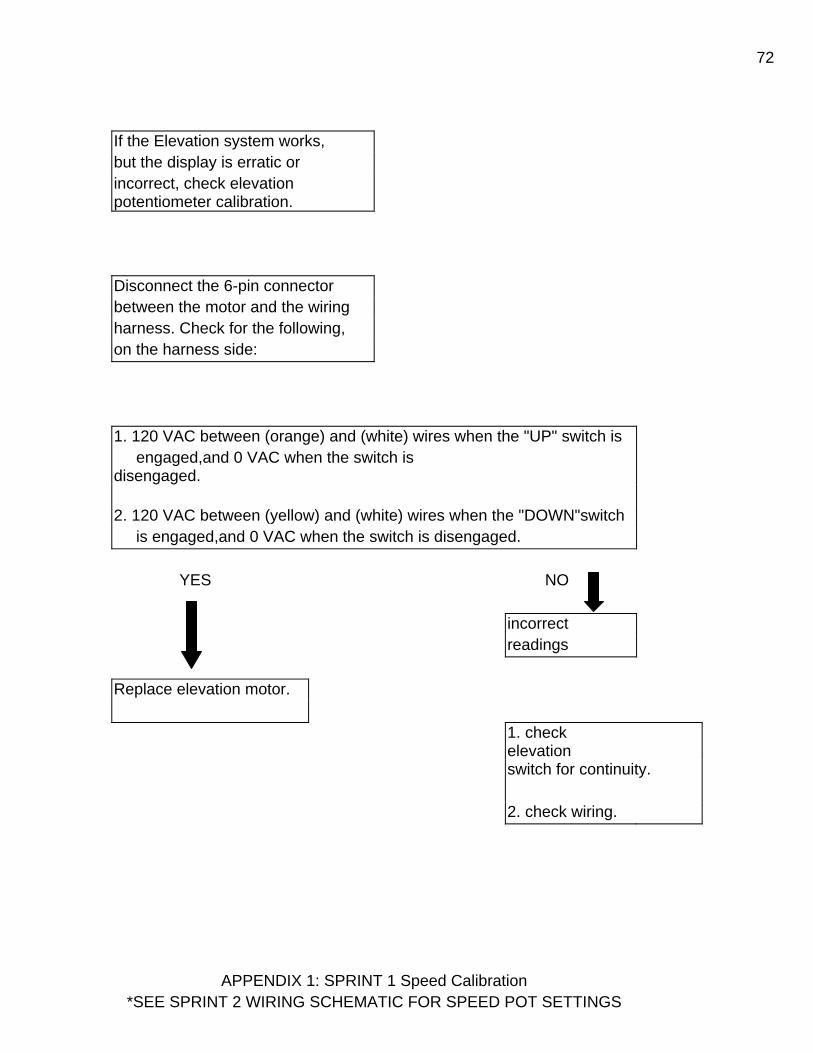
72
If the Elevation system works, but the display is erratic or incorrect, check elevation potentiometer calibration.
Disconnect the 6-pin connector between the motor and the wiring harness. Check for the following, on the harness side:
1. 120 VAC between (orange) and (white) wires when the "UP" switch is engaged,and 0 VAC when the switch is disengaged.
2. 120 VAC between (yellow) and (white) wires when the "DOWN"switch is engaged,and 0 VAC when the switch is disengaged.
YES NO incorrect readings
Replace elevation motor.
1. check elevation
switch for continuity. 2. check wiring.
APPENDIX 1: SPRINT 1 Speed Calibration *SEE SPRINT 2 WIRING SCHEMATIC FOR SPEED POT SETTINGS

73
STEP 1: Verify KBLC - 118 pot settings are as shown below KBLC - 118 SPRINT 1 MOTOR CONTROL BOARD 6:00 ACCEL 10:00 12:00 10:00 3:00 MAX MIN IR CL
STEP 2: Turn machine on, increase speed until 1.2 mph shows on display, then slowly decrease speed just until the display shows exactly 1.0 mph.
STEP 3: Adjust "MIN" pot on KBLC-118 until belt speed is between 0.95 - 1.00 mph using a tachometer OR 8.8 - 9.3 rpm counting belt revolutions.
STEP 4: Turn speed up to 8.8 mph ( on display ), then slowly increase speed just until display shows exactly 9.0 mph.
STEP 5: Adjust "MAX" pot on the KBLC-118 until the belt speed is between 8.95 - 9.00 mph ( or 83.0 - 83.4 rpm ).
STEP 6: Since the "MAX" and "MIN" pots will affect each other during the adjustment, it may be nessary to repeat steps 2 - 5 several times. Continue calibration until neither pot needs readjustment.
Appendix 2: Elevation System Calibration

74Note: The elevation system will need to be re -
calibrated:
1. After replacing the elevation motor. 2. After replacing the elevation potentiometer. 3. If the elevation readout appears inaccurate.
STEP 1: Remove the two screws holding the elevation potentiometer and pull the pot from the back of the elevation motor.
STEP 2: Turn the treadmill on in the diagnostic mode by holding down the “Select Display” button to switch the
treadmill on. Use the "SELECT DISPLAY" button to switch into elevation mode (both the "TIME" and "DISTANCE" LED’s will be lit).
STEP 3: Lower the treadmill until it is level (o% elevation).
STEP 4: Turn the elevation potentiometer until "168" (* 153 Sprint 2) shows in the display.If the number in the display does not change as the pot is turned, the pot is broken and must be replaced (check with an ohmmeter to verify)
STEP 5: Carefully push the potentiometer back into the elevation motor and tighten it back down. Be careful that the reading on the display does not change while the pot is being re - installed. Turn the machine off, turn it back on normally, and verify that the elevation system works
correctly.

75
TRACKING AND TENSIONING
Proper tensioning of the Treadbelt and Drive Belt are necessary to insure smooth operation and long life for your treadmill. As these components may stretch as part of their normal break in period it is one of the few things we ask our customers to do in maintenance of their treadmills. The following illustrates how to tension the Treadbelt and Drive Belt.
Check Drive Belt tension
Drive Belts are pretensioned before the treadmill leaves the factory. Adjustments are ONLY necessary when Drive Belt is slipping during use. To test for tightness: 1. Remove motor cover. 2. With mill running at 2mph walk on treadbelt. 3. If Drive Belt is moving front roller with no slippage then drive belt is correctly tensioned. Check the tension on the Drive Belt by placing the Drive Belt between your thumb and forefinger and twisting. The proper twist is 45°. If the belt needs to be adjusted use a 7/16” socket and turn the bolt underneath the motor pan attached to the hook screw. CAUTION: NEVER OVERTENSION THE DRIVE BELT. TIGHTEN ONLY TILL SLIPPING STOPS. OVER TIGHTENING MAY CAUSE SERIOUS DAMAGE TO THE DRIVE MOTOR AND WILL VOID THE MOTOR’S WARRANTY.

76TREADBELT TRACKING The Treadbelt is TRACKED by means of two adjustment bolts (9/16" wrench) located at rear of treadmill. By tightening the side the belt is closest to and loosening the opposite side by the same amount, you change the alignment of the rear roller without changing overall tension. Adjustments should be made with treadmill running, and should be made in 1/4-turn increments. Allow at least 30 seconds for treadbelt to stabilize between each adjustment. Perform the adjustments at slower speeds (2-3 mph) until you are comfortable making adjustments. Faster speeds will cause the adjustments to take effect quicker (5-6 mph). Example: Treadbelt tracks to the right: a. Turn treadmill on, and bring speed up to 4.0 mph. b. Using a 9/16" wrench, tighten the right-hand adjustment bolt 1/4" turn. c. Loosen the left-hand adjustment bolt 1/4" turn. d. Let Treadbelt stabilize (rotate for 30 seconds) and readjust if necessary. TREADBELT TENSIONING Treadbelts are tensioned at the factory and normally need no adjustment. To determine if treadbelt needs to be adjusted perform the following test: 1. Remove motor cover. 2. Set treadmill speed to 2mph. 3. Walk on treadbelt and see if drive roller is turning but belt is not moving. If belt is not moving then
tension treadbelt ONLY until belt ceases to slip. The same adjustment bolts used for tracking TENSION the Treadbelt. To tighten Treadbelt, turn both adjustment bolts (clockwise) exactly the same amount. Failure to turn them equally will affect belt tracking. You are moving the rear roller closer or further away from the deck to tension the Treadbelt. DO NOT OVER TIGHTEN TREADBELT / DRIVE BELT! If you can't reach the palm of your hand under the center of the Treadbelt, if the edges of the belt are curled up, or if you hear the belt “groaning” THE TREADBELT IS TOO TIGHT.
*If normal tracking procedures are not working satisfactorily, proceed with the following
MAKE SURE TREADMILL IS LEVEL!
Make sure the treadmill is completely level. Place a carpenter's level across rear frame rails running parallel with rear roller. VERY IMPORTANT: Must have a minimum of 150 pounds on the treadmill’s side steps for the reading to be accurate. First try to move treadmil to more level flooring. If that is not an option use leveling shims. You either put something under the rear feet or install shims between the rear foot and the frame. Simply loosen the two Philips head screws and slide shim in place. Tighten screw and re-check that the treadmill is level.
DRIVE ROLLER ALIGNMENT: The Drive Roller is preset at the factory. However, if the Treadbelt is centered at the Rear Roller but is off center in the front, an adjustment will need to be made. The Drive Roller is secured to the frame with two hex head bolts. (3/8 wrench) The holes in the frame are elongated; this allows for forward and aft adjustment of the drive roller. Example: Treadbelt is tracking to the right hand side. Adjust right hand side of drive roller by moving it towards the front (motor side) of treadmill. The Treadbelt will move towards the center.
Recommended Maintenance

77Home Models- Vacuum around and underneath the treadmill on a monthly basis. Vacuum or wipe down the deck area between the treadbelt and frame. Wipe down display and handrails after every use. No other maintenance is required. Commercial Treadmills Once a week 1. Wipe down display with soft cotton cloth and mild soap and water.
Cloth should be damp not wet. Once a week or as needed. 2. Wipe down handrails and traction strips with soft cotton cloth and mild soap and water. Cloth
should be damp not wet. Once a week or as needed. 3. Vacuum or wipe down the Deck area between treadbelt and frame. Once a week. Once a Month 1. Take off Motor cover and vacuum. 2. Slide clean towel under Treadbelt and wipe deck and under the belt. Rotate belt 180 degrees and
repeat. 3. SlipCote under Treadbelt. 4. Check Drive Belt Tension 5. Check Treadbelt Tension and Tracking Every Six Months 1. Check Motor Brushes for wear. Dress Commutator if needed.
Instructions for lubricating treadmills with SlipCote SlipCote lubricant is designed to reduce friction between the treadbelt and slider deck. It is required for all institutional treadmills. Proper and timely application of SlipCote will prevent premature failures due to excessive wear and load. Items affected by inadequate lubrication are the treadbelt, slider deck, motor, and motor controller. When to lubricate: Landice institutional treadmills should be lubricated on a monthly basis. How to lubricate: Only use SlipCote by Landice. Most standard greases, waxes, and silicon sprays will build up on the deck and rollers and have an adverse effect on the longevity of the treadmill. Using a large syringe, such as a turkey baster, squirt 1/2 tube full of SlipCote underneath the center of the Treadbelt (1/2 Oz.). If you’re using our SlipCote packets, empty the entire contents of the packet under the center of the treadbelt. Walk for 1 minute on the treadmill at a speed of 1.0 mph. This will moisten about an 8" track underneath the center of the entire Treadbelt. Note: Do not get SlipCote on TOP of Treadbelt. This will make treadbelt very slippery and make treadmill dangerous to use. We recommend using rubbing alcohol applied to a sponge to remove any SlipCote on the treadbelt.
Cleaning display- Use mild solution of Non-Phosphate cleaner on damp soft cotton cloth.

78 Cleaning Treadbelt Walking Surface- Treadbelts can become dirty and unsightly when users track dirt onto them. If vacuuming doesn’t remove dirt, we recommend the use of a nylon bristle brush to remove dirt trapped in treadbelt surface. A damp (not wet!) sponge can be used to finish the cleaning process.
Institutional drive motor maintenance Yearly Institutional Maintenance: Replace the Drive Motor Brushes. Failure to do so will result in premature Drive Motor failure.
1. Unplug Treadmill. 2. Remove Motor Brush caps (2). 3. Remove Motor Brushes and inspect. They should be replaced if 1/4 inch or less. Inspect
motor Commutator for wear (Black-scoring present on copper segments) Try to dress out (clean up) Commutator with a Commutator stone or emery cloth.
4. When you reinstall motor brushes make sure the brush does not bind up in its holder. The motor brush must move freely the full length with zero resistance. If resistance is present you must carefully dress out the brush until the correct tolerance is achieved.
Motor brushes should be checked every 6 months on institutional treadmills and after 6 years on home units. SERVICE CHECK-LIST
Check Treadbelt tension and tracking Wipe underneath treadbelt Lubricate Treadbelt Check drive belt tension Check motor brushes and commutator Vacuum under motor hood Vacuum around and under treadmill

79Index
Description Page Number
5V LED Definition 20 Picture 18 Troubleshooting 54 12 VDC Power Supply
Definition 29 Picture 21-22 Removal/Replacement 40 Troubleshooting 61 Testing 32, 49, 70 Capacitor Definition 29 Picture 17-18 Removal/Replacement 39 Troubleshooting 55
Wiring 18 CE Error Code 50 Choke (Inductor) Definition 29 Picture 17-18 Removal/Replacement 39 Troubleshooting 55 Wiring 18 Components Definitions 29-31 Parts list 14-16 Testing 32-34 Deck Definition 29 Removal/Replacement 44 Display Panels 10-13 Drive Belt Definition 29 Picture 76 Tensioning 76-77 Troubleshooting 35, 36, 76

80 Drive Motor Definition 29 Picture(Motor Pan) 17, 21 Removal/Replacement 41
Testing 32 Troubleshooting 47-48
Drive Motor Brushes Maintenance 32
Removal/Replacement 41 Troubleshooting 35, 36, 47, 55, 63 Drive Roller w/Sheave Definition 29 Removal/Replacement 45 Troubleshooting 35, 46, 77 Elevation Leg Assembly Definition 29 Picture 42 Removal/Replacement 44 Elevation Motor Calibration 43, 59, 64, 65
Definition 29 Picture 17, 21, 42, 43, Removal/Replacement 42
Testing 33 Troubleshooting 20, 47, 48, 58, 73, 75
Wiring 18, 22 Elevation Potentiometer Calibration 43, 59, 65, 75 Definition 29 Picture 18, 22, 25, 26, 27 Testing 33 Troubleshooting 20, 58, 64, 73 Error Codes 50 Face Plate Definition 29 Removal/Replacement 41
Testing 33 Picture 13
Frame (Side) Definition 29

81Frame Covers (Side) Definition 30 Fuses 54, 61, 70 IR Potentiometer Definition 30, 37 Adjustments 37, 74 Troubleshooting 36 L5 (LS) Error Code 50 Troubleshooting 55, 56, 62, 63 LED LIGHTS SCR 19-20 PWM 23 RELAY 24 Maintenance 53, 78, 79 Membrane Panel Definition 30 Picture 10, 11, 12, 13 Removal/Replacement 41
Testing 33 Troubleshooting 57 Noises 46-48 O5 (OS) Error Code 50 Parts List 14-16 PO Error Code 20, 33, 50 Power Cord (Line Cord) Removal/Replacement 39 Troubleshooting 36, 49 PWM Motor Control Board Definition 30 LED Lights 23 Picture 21, 22 Removal/Replacement 39 Testing 33 Troubleshooting 33, 37, 38, 49 Wiring 22, 25, 27

82Relay Board Definition 30 LED Lights 24
Picture 21 Removal/Replacement 40
Testing 34 Troubleshooting 24, 61, 63 Wiring 22
Safety Lanyard Definition 30 Troubleshooting 52, 57, 68, 70
SCR Motor Control Board Definition 30 LED Lights 19-20
Picture 17 Removal/Replacement 39 Testing 33-34 Troubleshooting 54, 55, 56, 58 Wiring 18 SlipCote Lubricant Definition 30 Use 78-79 Troubleshooting 46 Speed Calibration 38 Speed Sensor Definition 30 Picture 17, 21 Testing 34 Troubleshooting 50, 56, 62, 67 Wiring 18, 22 Take Up Roller Definition 30 Removal/Replacement 44 Troubleshooting 46-47 Treadbelt Cleaning 78 Definition 31 Picture 21 Removal/Replacement 44 Tracking/Tensioning 53, 76, 77 Troubleshooting 35, 36, 46, 47, 48

83 Upper Display Board Definition 31 Removal/Replacement 40 Troubleshooting 54, 57, 61, 68, 70 Testing 34 Uprights (Frame) Definition 31 Upper Wire Harness Definition 31 Troubleshooting 49, 54, 61, 70 Voltage Specifications 7-9
Testing 49