80736 cover lao 1 18/12/2012 16:12 page 1 j ci/sfb (41) r...
TRANSCRIPT

facades
facadesC
I/SfB
(41)R
January 2013 (editio
n 5)
CI/SfB (41) R
January 2013 (edition 5)
80736_COVER_Layout 1 18/12/2012 16:12 Page 1
2 Facades
About this guide‘Facades’ is exclusively focused on the design,
detailing and specification of Marley Eternit
architectural fibre cement cladding material.
The information contained within Facades is
comprehensive and designed to inform and inspire.
For more detailed information and advice on
bespoke projects, please speak to our experienced
and knowledgeable Technical Advisory Team on
Tel: 01283 722588.
EQUITONE [natura] EQUITONE [tectiva] EQUITONE [pictura] EQUITONE [textura] Other facades
The Marley Eternit range
This publication is based on the latest data available at the time of printing. Due to product changes, improvements and other factors, the Company reserves the right tochange or withdraw information contained herein without prior notice. For specific applications users should refer to the Technical Advisory Service and relevant Standards and Codes of Practice for guidance.
The photography shown in the document should not necessarily be taken as recommendations of good practice. The printing process restricts the exact representation ofcolours. For true colour reference, please request product samples.
80736_COVER_Layout 1 18/12/2012 14:48 Page 2
Contents 3
Contents
4-5 Introduction
6-7 Range overview and fixing system selector
8-19 Applications and sectors
20-43 Design considerations
44-85 Facade material
86-115 Fixing systems
116-119 Health, safety and sitework
120-125 Sustainability and the environment
126-128 Services
129 References
131 Index
facades

4 Introduction
Equitone
[natura] , Office
Building, Nam
ur, B
elgium

”
Introduction 5
“Marley Eternit Limited is at the forefront of
the design, development and supply of
lightweight fibre cement rainscreen facades
and fixing solutions.
Rainscreen is a fast-track, sustainable
solution for both refurbishment and
new build projects. It is also a dry trade
that aligns well with modern methods of
construction, and offers both contemporary
and flexible design options and versatility
in the construction process.

6 Range overview
Range overview
Marley Eternit is committed tosustainable manufacture of high quality,high performing facade solutions.
Our range of products is manufacturedunder quality management systems,which meet the requirements of ISO9001 and environmental systems which comply with the internationallyrecognised ISO 14001 standard.
The through coloured material allows the texture of the fibres to show
through, offering a unique visual appearance. This, combined with an
extensive colour choice, provides a high degree of flexibility and an
aesthetically appealing finish.
‡ Morepages 46-51 EQUITONE [natura]
samples Tel 01283 722588
web marleyeternit.co.uk/facades
This through-coloured material offers elegant shades of natural colour.
Each panel is characterised by fine sanded lines and naturally occurring
hues which provide a unique aesthetic effect.
‡ Morepages 52-57 EQUITONE [tectiva]
samples Tel 01283 722588
web marleyeternit.co.uk/facades
Advantages• Can achieve an A+ rating as defined in the BRE Green Guide*
• Fire classifications A2-s1, d0 to EN 13501-1
• Installed life expectancy of at least 50 years
• Designed for rainscreen cladding systems
• Excellent weather and chemical resistance
• Durable facade material
• Resistant to impact damage
• Resistant to insects, mould growth and fungi
• No routine maintenance required
• BBA Certificate No. 06/4355
* Based on generic rating for autoclaved fibre cement single sheet (Element Ref: 80623042, 806230422, 806230447, 806230450)
[natura] [tectiva]

Range overview 7
EQUITONE [textura] fibre cement panels have a highly glazed and textured
finish. A wide range of colours, including factory approved RAL colours,
are available ensuring the right colour for your project.
‡ Morepages 64-69 EQUITONE [textura]
samples Tel 01283 722588
web marleyeternit.co.uk/facades
EQUITONE [pictura] is coated with an additional surface treatment, providing
a hard, smooth, silky matt surface. Available in a variety of shades
allowing flexibility of design.
‡ Morepages 58-63 EQUITONE [pictura]
samples Tel 01283 722588
web marleyeternit.co.uk/facades
Other facadesOperal 72-73
Cedral Weatherboard 74-77
Bluclad 78-81
‡ Moresamples Tel 01283 722588
web marleyeternit.co.uk/facades
Fixing system selector – EQUITONE
[natura] [tectiva] [textura] [pictura]
Screws ¸ ¸ ¸ ¸
Rivets ¸ ¸ ¸ ¸
Omega & Zed ¸ ¸ ¸ ¸
Ventispan ¸ ¸ ¸ ¸
Ventisol ¸ ¸ ¸ ¸
Mechanical¸ ¸ ¸
secret fix
Structural¸ ¸** ¸ ¸
bonding
** with restriction, please contact our Technical Advisory Team on Tel: 01283 722588.
‡ Morepages 86-115 Fixing systems
samples Tel 01283 722588
web marleyeternit.co.uk/facades
Profiled Sheeting 82-83
Vertical tile hanging 84-85
[pictura] [textura]

8 Applications and sectors
healthcare
standardsnew build
comclient satisfaction
refurbishmenthousing

Applications and sectors 9
10-11 Overcladding
12-19 Healthcare, Education, Commercial & Housing
mercialeducation
Applicationsand sectors
local authorities

10 Applications and sectors
Overcladding
Prior to overcladding
Project: St Bede’s CatholicHigh School
Location: Lytham St Annes
Application: Education
Product: EQUITONE [natura]
Colour: Morning Mist, Anthracite and Natural Grey
Specifier: Cassidy & Ashton
Over time, buildings can become dated and
look 'tired'. Alongside this, other problems
may arise, including heat loss and the need
for frequent maintenance to the existing facade
material. Overcladding with one of Marley
Eternit's cladding ranges, as part of a
rainscreen system, can be a cost-effective
solution to increase both visual appeal and
thermal performance.

Applications and sectors 11
Application: Residential
Product: EQUITONE [textura]
Project size: 2200m2
Heating energy requirement per month (kWh/m²)25
20
15
10
5
02009
October2009
November2009
December2010
January2010
February
Overclad
Un-clad
Overclad with a rainscreen system
42% saving on heating costs
Un-clad
Overcladarea
Un-clad area
Fixing: Aluminium section wallbracket with thermalbreak element, T- andL-sections
Insulation: Mineral wool
Average energy saving: More than 40%

12 Applications and sectors
EQUITONE[natura] , University Cam
pus, York

Applications and sectors 13
EQUITONE [tectiva] , Office
Building, Casab
lanc
a, M
oroc
coCed
ral W
eatherbo
ard, Hotel, Z
aand
am, T
he Nethe
rland
s
14 Applications and sectors
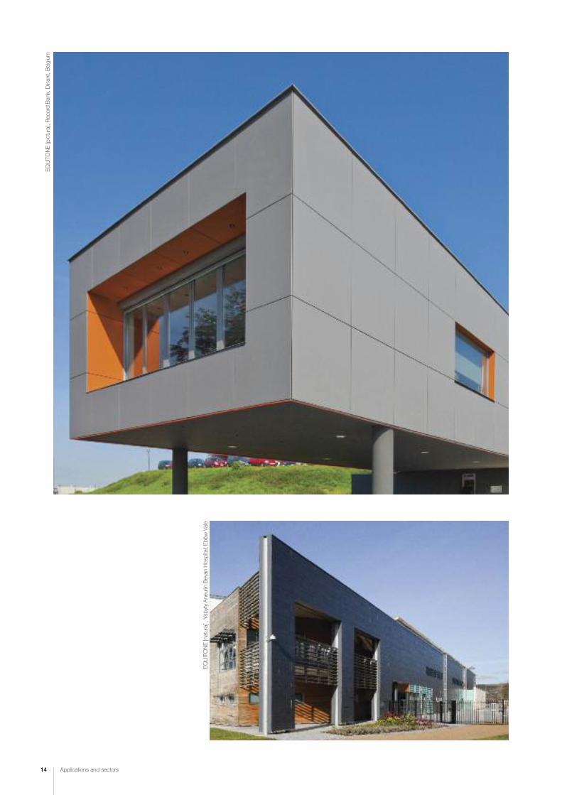
EQUITONE [natura] , Ysb
yty Ane
urin Bevan Hospital, Eb
bw Vale
EQUITONE [pictura], Rec
ord Bank, Dinant, Belgium

Applications and sectors 15
EQUITONE[natura] , Reh
abilitation Cen
tre, Luxem
bourg

16 Applications and sectors
EQUITONE[natura] , Office
Building, Cardiff

Applications and sectors 17
EQUITONE[natura] , Private Hou
se, U
trech
t, Th
e Nethe
rland
s
EQUITONE [tectiva] , Private Hou
se, B
land
en, B
elgium
EQUITONE[natura] , Arts Com
plex, G
oole

18 Applications and sectors
EQUITONE[natura] , Northern Design Cen
tre, G
ateshe
ad
EQUITONE [textura], W
eston College
, Weston Sup
er M
are

Applications and sectors 19
EQUITONE [textura], A
rt College
, Manch
ester

ApprovedDocument B
standardsrainscreen
aesthetics
20 Design considerations
fire resistance
thermal performance
22-23 Rainscreen claddingprinciples and benefits
24 Rainscreen and overcladding
25 Rainscreen and wall insulation
26-27 Aesthetics and colour
28-29 Recommended design procedure
30-31 Legislation, guidance and reference
32-33 Wind resistance
34-37 Acoustics, condensation,ventilation and fire safety
38-39 Thermal insulation
40-42 Thermal design details
wind resistance
colourDesign considerations
Design considerations 21
1
2
3
4
5
22 Design considerations
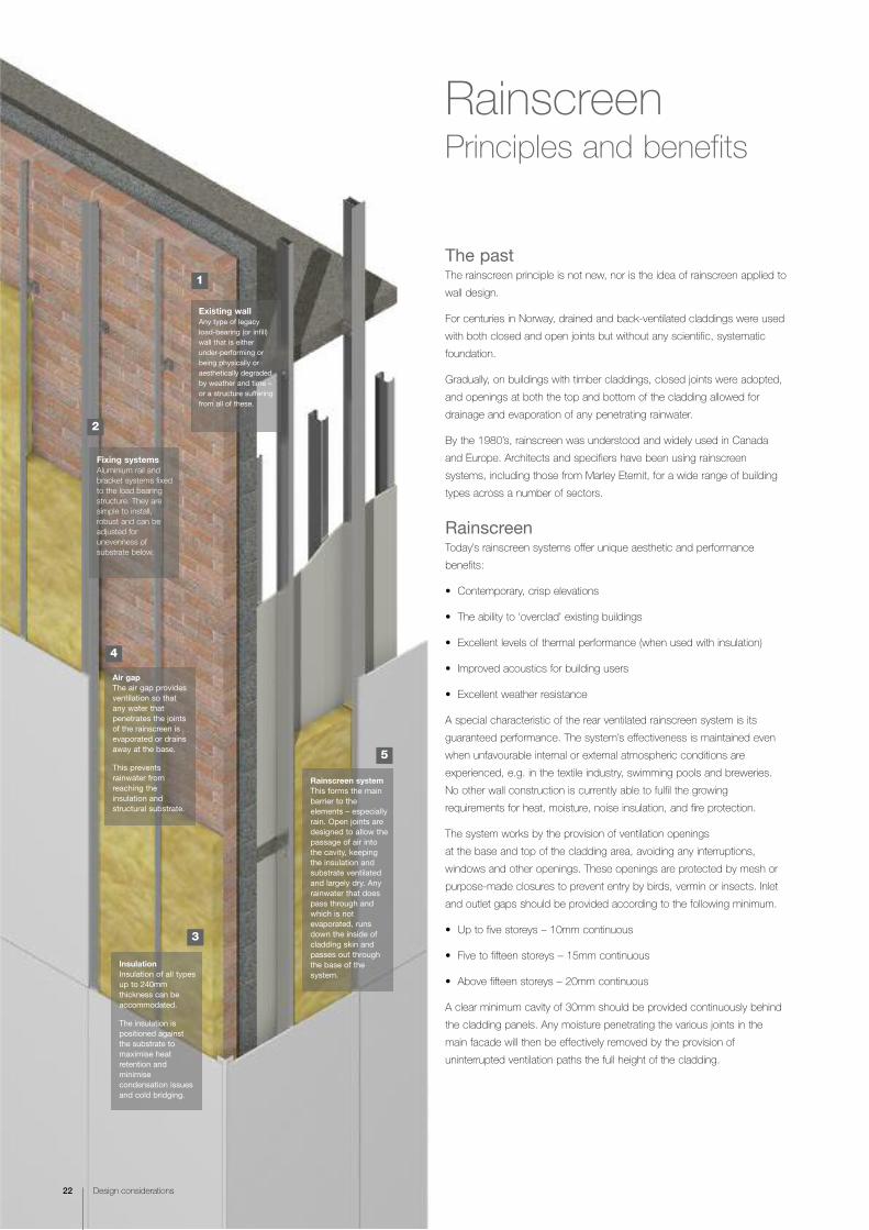
The past The rainscreen principle is not new, nor is the idea of rainscreen applied to
wall design.
For centuries in Norway, drained and back-ventilated claddings were used
with both closed and open joints but without any scientific, systematic
foundation.
Gradually, on buildings with timber claddings, closed joints were adopted,
and openings at both the top and bottom of the cladding allowed for
drainage and evaporation of any penetrating rainwater.
By the 1980’s, rainscreen was understood and widely used in Canada
and Europe. Architects and specifiers have been using rainscreen
systems, including those from Marley Eternit, for a wide range of building
types across a number of sectors.
RainscreenToday’s rainscreen systems offer unique aesthetic and performance
benefits:
• Contemporary, crisp elevations
• The ability to ‘overclad’ existing buildings
• Excellent levels of thermal performance (when used with insulation)
• Improved acoustics for building users
• Excellent weather resistance
A special characteristic of the rear ventilated rainscreen system is its
guaranteed performance. The system’s effectiveness is maintained even
when unfavourable internal or external atmospheric conditions are
experienced, e.g. in the textile industry, swimming pools and breweries.
No other wall construction is currently able to fulfil the growing
requirements for heat, moisture, noise insulation, and fire protection.
The system works by the provision of ventilation openings
at the base and top of the cladding area, avoiding any interruptions,
windows and other openings. These openings are protected by mesh or
purpose-made closures to prevent entry by birds, vermin or insects. Inlet
and outlet gaps should be provided according to the following minimum.
• Up to five storeys – 10mm continuous
• Five to fifteen storeys – 15mm continuous
• Above fifteen storeys – 20mm continuous
A clear minimum cavity of 30mm should be provided continuously behind
the cladding panels. Any moisture penetrating the various joints in the
main facade will then be effectively removed by the provision of
uninterrupted ventilation paths the full height of the cladding.
Rainscreen Principles and benefits
Existing wallAny type of legacyload-bearing (or infill)wall that is eitherunder-performing orbeing physically oraesthetically degradedby weather and time –or a structure sufferingfrom all of these.
Fixing systemsAluminium rail and
bracket systems fixed
to the load bearing
structure. They are
simple to install,
robust and can be
adjusted for
unevenness of
substrate below.
InsulationInsulation of all typesup to 240mmthickness can beaccommodated.
The insulation ispositioned againstthe substrate tomaximise heatretention andminimisecondensation issuesand cold bridging.
Air gapThe air gap providesventilation so thatany water thatpenetrates the jointsof the rainscreen isevaporated or drainsaway at the base.
This preventsrainwater fromreaching theinsulation andstructural substrate.
Rainscreen systemThis forms the mainbarrier to theelements – especiallyrain. Open joints aredesigned to allow thepassage of air intothe cavity, keepingthe insulation andsubstrate ventilatedand largely dry. Anyrainwater that doespass through andwhich is notevaporated, runsdown the inside ofcladding skin andpasses out throughthe base of thesystem.

Design considerations 23
Insulation• Insulation of up to 240mm thickness can be accommodated
using a Marley Eternit framing system
• All types of insulation can be used – from rigid PUR to
mineral wool
• Insulation positioned against substrate maximises heat retention
and minimises condensation issues
• Externally located insulation maximises internal floor space
• Mineral wool insulation allows moisture to pass through to the
cavity where passage of air evaporates it
Rainwater removal• Cladding prevents penetration of most rainwater
• Natural ventilation – stack effect – evaporates penetrating rain
• Residual rainwater drains harmlessly and evacuates at base of system
• Pressure equalised system naturally inhibits ingress of driven rain
Removal of interstitial condensation• Thermally efficient system
• Any interstitial condensation kept to outside of structure
• Quickly removed via evaporation
• Structure maintained at even temperature
• Structure temperature kept above dew point
Minimisation of thermal bridging • Continuous insulation envelope possible
• Insulation is external, so no thermal breaks required to accommodate
internal structural elements such as floors and beams
24 Design considerations
Rainscreen and overcladding
The aesthetic, remedial and thermal solutionOne of the key ways in which rainscreen can benefit existing buildings is
through overcladding.
Apartment and office blocks, retail, healthcare and commercial
establishments may well require both remedial and aesthetic work to
make them suitable for today's environment.
On top of this, the thermal inefficiencies inherent in this legacy building
stock will almost certainly need radically upgrading to meet today’s
exacting regulations.
Overcladding with rainscreen cladding systems achieves all three key
requirements:
• Remedial
• Aesthetic
• Thermal (with insulation)
Other benefitsMinimising disturbanceOvercladding is carried out entirely from the outside, so there
is usually minimal disruption.
BalconiesBalconies and walkways can be fully enclosed to create buffer
zones. If external wall insulation is not considered then enclosing
the balconies will also reduce the effect of the thermal bridges
associated with them.
VandalismThose external wall surfaces prone to vandalism and graffiti – for
instance, at ground floor level – can be clad with more suitable material
or one such as EQUITONE [natura] incorporating the UV Pro coating
offering good protection against graffiti and subsequent removal.
MaintenanceAs a non-loadbearing extra ‘skin’, fixed to the substrate, maintenance
or replacement of panels is straight-forward and non-invasive, as is
access to the loadbearing structure i.e., columns, beams and slabs.
Building lifeWhilst overcladding will not reinstate structural integrity of a building,
it will, if designed and installed correctly, extend its life by improving
weather resistance.
Key features for overcladding• Restoration of existing facade
• Extending the life of the building
• Improving appearance and image
• Provide thermal insulation and weather-tightness
• Improve acoustical performance of the building
• Lower maintenance cost
• All weather fix solution
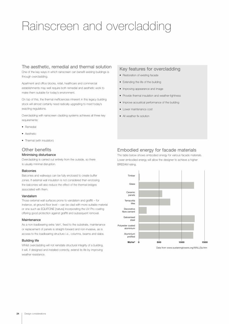
Timber
Glass
Ceramicpanels
Terracottatiles
Decorativefibre cement
Galvanisedsteel
Polyester coatedaluminium
Aluminiumprofiled
MJ/m2 0 500 1000 1500
Embodied energy for facade materialsThe table below shows embodied energy for various facade materials.
Lower embodied energy will allow the designer to achieve a higher
BREEAM rating.
Data from www.sustainingtowers.org/WALLSa.htm
Design considerations 25
Providing thermal insulation for wallsRainscreen is a relatively high-benefit, low-cost method of providing
thermal insulation to external walls for both refurb (overclad) and new
projects. It can also help minimise cold-bridging.
Adding insulation to the external surface of the loadbearing structure has
three key benefits:
• Increased thermal efficiency – dependent on the fixing system used.
Up to 240mm of insulation can be added using a Marley Eternit
framing system
• No loss of internal space - insulation added to wall cavities or inner
leaf inevitably consumes internal habitable space
• Light weight and easy to fix – insulation can be rapidly and easily fixed
to the exterior substrate and adds very little loading to the rainscreen
support system
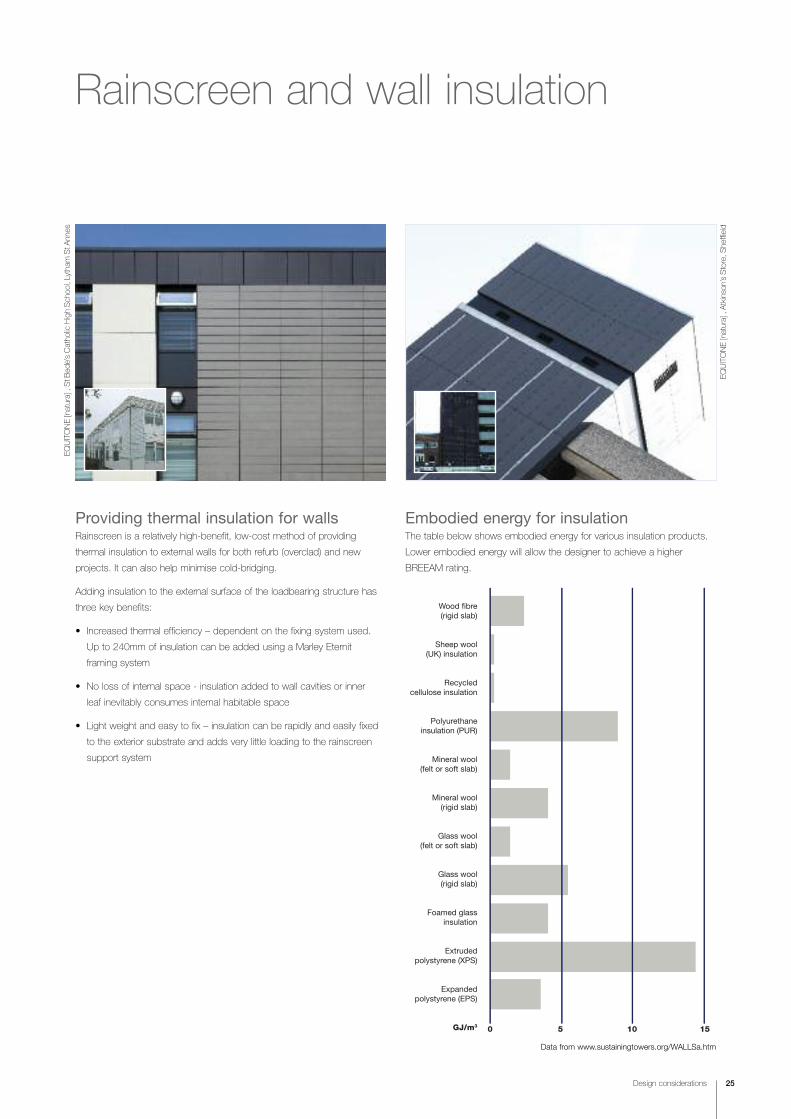
Wood fibre(rigid slab)
Sheep wool(UK) insulation
Recycledcellulose insulation
Polyurethaneinsulation (PUR)
Mineral wool(felt or soft slab)
Mineral wool(rigid slab)
Glass wool(felt or soft slab)
Glass wool(rigid slab)
Foamed glassinsulation
Extrudedpolystyrene (XPS)
Expandedpolystyrene (EPS)
GJ/m3 0 5 10 15
Embodied energy for insulationThe table below shows embodied energy for various insulation products.
Lower embodied energy will allow the designer to achieve a higher
BREEAM rating.
EQUITONE [natura] , St B
ede’s Catho
lic High Sch
ool, Lytham
St A
nnes
Rainscreen and wall insulation
Data from www.sustainingtowers.org/WALLSa.htm
EQUITONE [natura] , Atkinson’s Store, S
heffield
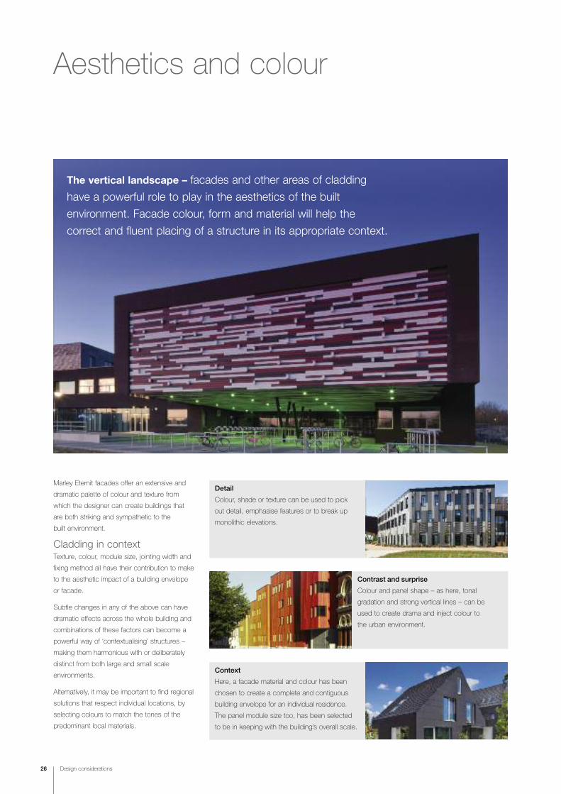
Context
Here, a facade material and colour has been
chosen to create a complete and contiguous
building envelope for an individual residence.
The panel module size too, has been selected
to be in keeping with the building’s overall scale.
Contrast and surprise
Colour and panel shape – as here, tonal
gradation and strong vertical lines – can be
used to create drama and inject colour to
the urban environment.
Detail
Colour, shade or texture can be used to pick
out detail, emphasise features or to break up
monolithic elevations.
Aesthetics and colour
26 Design considerations
The vertical landscape – facades and other areas of cladding
have a powerful role to play in the aesthetics of the built
environment. Facade colour, form and material will help the
correct and fluent placing of a structure in its appropriate context.
Marley Eternit facades offer an extensive and
dramatic palette of colour and texture from
which the designer can create buildings that
are both striking and sympathetic to the
built environment.
Cladding in contextTexture, colour, module size, jointing width and
fixing method all have their contribution to make
to the aesthetic impact of a building envelope
or facade.
Subtle changes in any of the above can have
dramatic effects across the whole building and
combinations of these factors can become a
powerful way of ‘contextualising’ structures –
making them harmonious with or deliberately
distinct from both large and small scale
environments.
Alternatively, it may be important to find regional
solutions that respect individual locations, by
selecting colours to match the tones of the
predominant local materials.

Design considerations 27
Economic module sizesMarley Eternit high performance fibre cement
panels can be made to any module and offer
the architect and designer wide design
freedom. Economics, however, play a
significant part in the selection of claddings
and should be considered. When designing,
the following information is aimed at providing
the specifier with guidance on the most
economic material usage from standard
sheets.
Sizes greater than half the maximum
manufacturing lengths become progressively
less economical in ratio to the distance
downwards from full length to half length as
indicated on the charts. The cost involved in
factory cutting of high performance facade
materials to exact sizes is small in relation to
the overall installed cost of facade systems
and it may be prudent in some cases to have
two small economic panels rather than one
large uneconomical panel.
For example an 800mm deep fascia would be
more economically clad using 1200mm panel
lengths rather than longer panels. The joints in
these cases can either be made a feature of
or hidden.
The shaded areas indicate the most uneconomic modules cut from a standard sheet (based on 1220 x 3040 sheet).
3040
2500
1520
1220
1000
800
600
400300
1220800600400
Panel fixingsThe fixing method chosen can have a
fundamental and dramatic effect upon the
final appearance of the clad building.
Employing a secret fix method, for example,
will result in a sheer, smooth facade
unobstructed by fixings.
An edge retention system, on the other hand,
focuses the eye upon the panel joints and will
give the facade a geometric feel, especially
when a contrasting colour is chosen for the
edge framing members.
The 'visible fixing' systems – screw and rivet
fixing – may be seen as providing an
appearance somewhere between secret fix
and edge retention. The smooth facade of
the cladding will be punctuated by the heads
of the rivets or screws, although, in practice,
these low profile fixings are virtually
unnoticeable.
Additionally, fixing methods can be combined
to create interesting design detail.
For example, a minimal amount of mechanical
fixing can be combined with structural
adhesive bonding.
The illustrations below show a diagrammatic view of the
generic differences in appearance between some typical
fixing systems. Please contact our Technical Advisory
Service for further information.
Visible fixing screw or rivet
Edge retention
Secret fix
Adhesive fix with squareboss at each corner

Building Information Modelling (BIM)Marley Eternit offer a range of BIM
resources for specifiers which ultimately
allow the generation of ‘As-built’ designs
and specification
‡ Morepage 128
www marleyeternit.co.uk/Resources/BIM
Recommendeddesign procedure
28 Design considerations
Designers are advised to consider the following steps when
commencing a design incorporating Marley Eternit products.
1. Checklegislation andplanning issues
The decisionmaking process
5. Select facade material (pages 44-85)
7. Determine fixingspecifications (pages 86-115)
3. Assess performancerequirements: acoustics, thermal,
fire, ventilation (pages 34-42)
4. Liaise with framework manufacturer or structural engineerto determine support rail framing
and design (page 32)
6. Select correct fixing method (pages 86-115)
2. Establish topography andexposure of site and assess windand rain resistance (pages 32-33)
9. Produce projectspecification and drawings
8. Select fittings andaccessories to meet
aesthetic and performancecriteria (pages 86-115)
ß
ß
ß
ßß
ß
ß
ß
ß
Reference should also be made to BS 8200
‘Code of Practice for the design of
non-loadbearing external vertical enclosures
of buildings’, also BS 6093 - ‘Code of Practice
for the design of joints and jointing in building
construction’, and to BS 8000: Part 6:
‘Workmanship on Building Sites: Code of
Practice for slating and tiling of roofs and
claddings’.
(The following information is provided for
guidance only. Designers should ensure that
they make all the necessary calculations and
take into account all aspects of the specific
project design and location.)
Further information can also be found in:
CWCT Standard for systemised building
envelopes, and NHBC Standards 2011.
EQUITONE [natura] , Brune
l University, U
xbridge
Design considerations 29
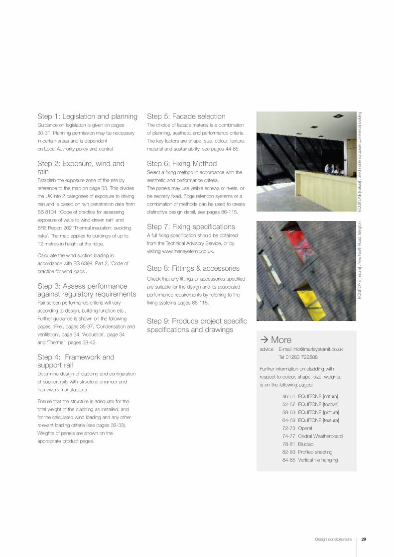
Step 1: Legislation and planning Guidance on legislation is given on pages
30-31. Planning permission may be necessary
in certain areas and is dependent
on Local Authority policy and control.
Step 2: Exposure, wind andrainEstablish the exposure zone of the site by
reference to the map on page 33. This divides
the UK into 2 categories of exposure to driving
rain and is based on rain penetration data from
BS 8104, ‘Code of practice for assessing
exposure of walls to wind-driven rain’ and
BRE Report 262 ‘Thermal insulation: avoiding
risks’. The map applies to buildings of up to
12 metres in height at the ridge.
Calculate the wind suction loading in
accordance with BS 6399: Part 2, ‘Code of
practice for wind loads’.
Step 3: Assess performanceagainst regulatory requirementsRainscreen performance criteria will vary
according to design, building function etc.,
Further guidance is shown on the following
pages: ‘Fire’, pages 35-37, ‘Condensation and
ventilation’, page 34, ‘Acoustics’, page 34
and ‘Thermal’, pages 38-42.
Step 4: Framework andsupport railDetermine design of cladding and configuration
of support rails with structural engineer and
framework manufacturer.
Ensure that the structure is adequate for the
total weight of the cladding as installed, and
for the calculated wind loading and any other
relevant loading criteria (see pages 32-33).
Weights of panels are shown on the
appropriate product pages.
Step 5: Facade selectionThe choice of facade material is a combination
of planning, aesthetic and performance criteria.
The key factors are shape, size, colour, texture,
material and sustainability, see pages 44-85.
Step 6: Fixing MethodSelect a fixing method in accordance with the
aesthetic and performance criteria.
The panels may use visible screws or rivets, or
be secretly fixed. Edge retention systems or a
combination of methods can be used to create
distinctive design detail, see pages 86-115.
Step 7: Fixing specificationsA full fixing specification should be obtained
from the Technical Advisory Service, or by
visiting www.marleyeternit.co.uk.
Step 8: Fittings & accessories
Check that any fittings or accessories specified
are suitable for the design and its associated
performance requirements by referring to the
fixing systems pages 86-115.
Step 9: Produce project specificspecifications and drawings
‡ Moreadvice E-mail [email protected]
Tel 01283 722588
Further information on cladding with
respect to colour, shape, size, weights,
is on the following pages:
46-51 EQUITONE [natura]
52-57 EQUITONE [tectiva]
58-63 EQUITONE [pictura]
64-69 EQUITONE [textura]
72-73 Operal
74-77 Cedral Weatherboard
78-81 Bluclad
82-83 Profiled sheeting
84-85 Vertical tile hanging
EQUITONE [natura] , New
North Roa
d, Islington
EQUITONE [natura] , used
inside
Europ
ean commercial building

Legislation, guidance and reference
30 Design considerations
StructureEngland and Wales: Part A ‘Structure’
Scotland: Technical handbook,Section 1 ‘Structure’
Northern Ireland: Part D ‘Structure’
Before contemplating a project incorporating a rainscreen
system, the designer and contractor must be aware of the
current legislation, the design requirements and standards
that govern and influence the style, parameters, performance,
products and construction of the project. The following section
summarises many of the relevant documents, but is by no
means exhaustive.
FireEngland and Wales:Part B ‘Fire Safety’
Scotland: Technical handbook,Section 2 ‘Fire’
Northern Ireland:Part E ‘Fire Safety’
MoistureEngland and Wales: Part C ‘Site Preparation andResistance to Moisture’
Scotland: Technical handbook, Section 3 ‘Environment’
Northern Ireland: Part C ‘Site Preparation andResistance to Moisture’
SoundEngland and Wales:Part E ‘Resistance to thepassage of sound’
Scotland:Technical handbook, Section 5 ‘Noise’
Northern Ireland:Part G ‘Sound insulation of dwellings’
VentilationEngland and Wales:Part F1 ‘Means of Ventilation’
Scotland:Technical handbook, Section 3 ‘Environment’
ThermalEngland and Wales:Part L ‘Conservation of fuel and power’
Scotland:Technical handbook, Section 6 ‘Energy’
Northern Ireland:Part F ‘Conservation of fuel and power’
Scottish Technical
HandbooksThe sections referred to aboveare contained in the two Scottish technical handbooks,one covering domestic construction, the other non-domestic.
NON-DOMESTICTECHNICAL HANDBOOKThe Scottish Building Standards
SCOTTISH BUILDINGSTANDARDS AGENCY
NON-DOMESTICTECHNICAL HANDBOOKThe Scottish Building Standards
SCOTTISH BUILDINGSTANDARDS AGENCY
DOMESTIC
Design considerations 31
Building RegulationsThese are mandatory regulations and, in
England and Wales, are generated and
approved by the Department for Communities
and Local Government (DCLG).
In Scotland they are generated and approved
by the Scottish Executive and in Northern
Ireland, by The Office Estates and Building
Standards Division (OBD).
They must be complied with for all new-build
and a great deal of refurbishment work.
They consist of the Building Regulations 2010
and The Building (Approved Inspectors etc.)
Regulations 2010, The Building (Scotland)
Amendment Regulations 2011, and the Building
(Amendment) Regulations (Northern Ireland)
2010.
Compliance with these regulations is the
responsibility of the building designer, who
may be the owner of the building, his appointed
architect, a structural engineer appointed by
the owner or his architect or, in the case of
small buildings, the actual builder.
The increasing complexity of construction and
the codes that govern design has
led many building designers to request the
specialist services of a cladding or building
envelope designer.
The Approved Documents of the Building
Regulations (England and Wales), the Technical
Handbooks (domestic and non-domestic)
(Scotland) and the Technical booklets (Northern
Ireland) provide practical guidance for some of
the common building situations in respect of the
requirements for materials and workmanship.
Copies of the Approved Documents that
accompany the Building Regulations 2010
(as amended) for England and Wales can be
downloaded from the Department for
Communities and Local Government (DCLG)
web site (www.communities.gov.uk) or obtained
from RIBA Bookshops, 15 Bonhill Street,
London EC2P 2EA. (Tel 020 7256 7222, Fax
020 7374 2737).
Copies of the complete set of Handbooks that
accompany the Building (Scotland) Regulations
2004 for Scotland can be downloaded from the
SBSA web site (www.sbsa.gov.uk). Follow the
links to 'Archive', 'Standards and Guidance'
then 'Technical Standards'. They can also be
obtained on a CD-Rom from the Scottish Building
Standards Agency (SBSA), Denholm House,
Almondvale Business Park, Livingston, EH54 6GA
(Tel 01506 600400, Fax 01506 600401.
Copies of the Northern Ireland Technical
Handbook can be downloaded from
www.buildingcontrol-ni.com/site
British StandardsA British Standard is a published document
that contains a technical specification or other
precise criteria designed to be used
consistently as a rule, guideline, or definition.
They are a summary of best practice and are
created by bringing together the experience and
expertise of all interested parties – the producers,
sellers, buyers, users and regulators of a
particular material, product, process or service.
Standards are designed for voluntary use and
do not impose any regulations. However, laws
and regulations may refer to certain standards
and make compliance with them compulsory.
The principal British Standards relevant to
this document are:
BS 5534 Gives recommendations for the
design, materials, application, installation and
performance of slates, tiles, shingles and
shakes. It also covers their associated fittings
and accessories for use in the construction of
pitched roofs and vertical cladding applications.
(BS 5534 should be read in conjunction with
BS 8000-6)
BS 5588 Fire precaution in the design,
construction and use of buildings.
BS 6093: 2006 Design of joints and
jointing in building construction.
BS 8200: 1985 Code of Practice for design
of non-loadbearing external vertical enclosures
of buildings.
BS 476-6: 1989 Fire tests on building materials
and structures – Method of Test for fire
propagation for products.
BS476-7: 1997 Fire tests on building materials
and structures – Method of test to determine
the classification of the surface spread of flame
of products.
BS EN 12467: 2004 fibre cement flat sheets,
product specification and test methods.
Provides information on the technical
requirements.
BS EN 13501-1: 2002 fire classification of
construction products and building elements –
Classification using test data from reaction to
fire tests.
BS 8000-6: ‘Workmanship on building sites.
Code of practice for slating and tiling of roofs
and claddings’. Applies to the laying and fixing
of claddings and their associated fixings and
accessories. Common Arrangement of Work
Section (CAWS) classifications H60, H61
and H65.
BS 5250: ‘Control of Condensation in Buildings’
Describes the causes and effects of surface
and interstitial condensation in buildings and
gives recommendations for their control.
Health and safetyTo ensure safe working practices during
construction, the designer should consider
relevant safety regulations. These include the
Construction (Design and Management)
Regulations and the Health and Safety
Executive’s approved code of practice for
management of health and safety at work.
Certain advisory bodies such as the National
House Building Council (NHBC), Loss
Prevention Council (LPC), Building Research
Establishment Ltd (BRE) and Timber Research
and Development Association (TRADA) also
produce recommendations and guidance on
construction which should be considered.
‡ Morepages 118-119 ‘Health, safety
and sitework guidance’
129 ‘References’

Wind resistance
32 Design considerations
Reaction of wind flow to obstructionDirections of pressures generated by wind force
suctionzone
wind
+ – –
30° and above
cladding. The provisions of all current codes of
practice, including that for the UK are intended
to give design loadings for typical impermeable
buildings and do not provide data in the
required form to enable the loading on
permeable overcladdings to be assessed.
The response of the Ventisol overcladding
system to wind loading has been determined by
direct measurements. A system performance
specification has been defined with which the
actual performance is shown to comply.
Using this system performance, a computer
based numerical model of the behaviour of the
system when installed on a building has been
developed and run for a number of typical
installations. It is concluded that the maximum
nett suction on the standard system without
fire-stops can be taken as one-half of the
design external wind pressure.
* Note: BS 6399-2 was superseded by Eurocode EN 1991-1-4 in 2010. Please also refer to note on Eurocodes on page 33
subject to suction.
Design for wind loadingThe standard method in BS 6399-2 ‘Loading
for buildings – Code of practice for wind loads’
should be used to determine the basic wind
speed of the site, which is then used to
calculate the effective wind speed and dynamic
wind pressure on the envelope, by applying a
series of factors to account for terrain,
topography, building height and length etc.
Wind loadingCalculate the dynamic pressures of the wind
(including the appropriate pressure coefficients
for the building) in accordance with BS 6399-2
wind loading or EN 1991-1-4.
The spacing of the profiles and brackets is
determined by calculation once the wind forces
on the structure have been determined. The
Ventisol system has been wind tested by the
Building Research Establishment (BRE) and is
classified as permeable when applied to
nominally impermeable walls. In this situation, a
large proportion of the external wind pressure is
able to leak through the cladding to act directly
on the building wall, relieving the loads on the
Pressure distribution in relation to roof pitch
suctionzone
wind30° and below
+
–
Wind forces on buildingsEach year, as many as 200.000 buildings in the
UK may be damaged by gales. Wind blowing at
90° to a building is slowed down when it hits
the surface of the building, with a consequent
build-up of pressure. At the same time, it is
deflected around the end walls and over the
roof, creating areas of negative pressure or
suction. The stronger the wind, the greater the
suction.
The force of the wind acting on the windward
face of a building creates a positive pressure,
although, even here, there are areas where
suction develops. Leeward faces are always

Design considerations 33
York
Inverness
Aberdeen
DundeePerth
EdinburghGlasgow
Oban
Newcastle
LeedsPreston
Liverpool
Stoke
LeicesterBirmingham
Kingstonupon-Hull
Manchester
Sheffield
Norwich
BedfordIpswich
Northampton
Oxford
Aberystwyth
Swansea
Cardiff BristolLONDON
BrightonBournemouth
Plymouth
Londonderry
Belfast
26
27
28
30
29
26
23
21
24
25
2324
31
23
24
Carlisle
Nottingham
24
23
24
25
25
20
22
25
23
‡ Moreadvice E-mail [email protected]
Tel 01283 722588
web marleyeternit.co.uk/facades
Basic wind speed*
Basic wind speeds
31 Basic wind speed Vb (in m/s)
* Derived from BS 6399-2
Note: Channel Islands basic wind speed = 24 m/s
Choice and type of anchorConsideration must be given to:
a) the strength and state of the existing
structure.
b) the capability of the chosen anchor to accept
the live and dead loads imposed, and an
adequate safety factor.
Aircraft vorticesFacades near airports can experience high local
wind load forces due to air vortices created
by certain aircraft when taking off and landing,
which may be greater than the calculated wind
loads to BS 5534. Designers should seek
advice from the Airport Authority Planning
Department when designing in these locations.
EurocodesA set of structural BS EN Eurocodes was introduced throughout
Europe in 2010 to replace conflicting national structural design
standards. The British Standards they have replaced continue
to have ‘deemed-to-satisfy’ status. However, designers must
consider the appropriate use of relevant standards and be
aware of the risk of inappropriately mixing BS EN standards
and withdrawn BS design standards.
The BS EN standards that are relevant to this section are
BS EN 1991-1-1:2002 ‘General Actions’, replacing BS 6399-1
BS EN 1991-1-4:2005 ‘Wind Actions’, replacing BS 6399-2
BS EN 1991-1-7:2006 ‘Accidental Actions’, replacing BS 6399-1

Acoustics, condensation, ventilation and fire safety
34 Design considerations
AcousticsBuilding Regulations
The relevant document governing
acoustic design, especially for
dwellings, is Building Regulations
Approved Document E
‘Resistance to the passage of
sound’ within which, the relevant
sections are:
E1: Protection of sound from other parts of
the building and adjoining buildings.
E2: Protection against sound within a dwelling
house.
Other documentation, such as (HTM) Health
and Technical Memoranda 56 and 2045 for
hospitals and Building Bulletin (BB) 87 and
93 for schools, offers guidance on meeting
Building Regulations for specific building types.
BS 5821 detailing the ‘methods for rating the
sound insulation in buildings and of building
elements’, is also relevant.
Resistance to the passage of sound
Approved Document E deals with the
resistance of both airborne and impact sound
generated within buildings, and requires that
dwellings, flats and rooms for residential
purposes shall be designed and constructed
in such a way that they provide reasonable
resistance to sound from other parts of the
same building and from adjoining buildings.
Separate requirements apply to schools, where
each room or space in the building shall be
designed so that it has the acoustic conditions
and the insulation against disturbance by noise
appropriate to its intended use.
Further information can be obtained by
reference to BS 8233 ‘Sound insulation and
noise reduction in buildings’ and BS EN ISO
717-1 ‘Acoustics – Rating of sound insulation
in buildings and of building elements. Part 1
Airborne sound insulation’, and BS EN ISO
717-2 ‘Acoustics – Rating of sound insulation
in buildings and of building elements. Part 1
‘Impact sound insulation’.
Condensation and ventilationBuilding Regulations
Approved Document C ‘Site
preparation and resistance to
moisture’ contains information
relating to the control of and
resistance to condensation in
buildings.
Approved Document Part F1
‘Means of ventilation’.
Contains information on the
provision of natural and
mechanical ventilation for
buildings. This is with specific
reference to the reduction and
removal of condensation.
Control of condensation
Condensation has become more of a problem
with the increase in highly insulated buildings.
Moreover, changes in lifestyle have led to higher
levels of water vapour in modern buildings. This
water vapour naturally ascends to the roof
space, where it condenses on contact with
cooler surfaces. Further condensation is likely to
be caused by climatic conditions, and may
eventually result in timber rot, metal corrosion
and damage to insulation and fittings.
BS 5250 states that the designer should
take account of the following moisture
sources in buildings:
• water incorporated during the construction
process (including precipitation);
• precipitation after construction;
• water vapour arising from the occupants
and their activities;
• temporary condensation occurring when
cold weather conditions are followed by
warm, humid weather.
Rainscreen
Rainscreen cladding systems, with insulation
applied to the outside of the building and a rear
ventilated cavity are an excellent way of
minimising internal moisture. The condensation
sometimes associated with internal insulation
simply does not occur. The moisture that
penetrates the rainscreen is quickly evaporated
by ventilation passing up through the system.
No other wall construction is currently able to
fulfil the growing requirements for heat,
moisture, noise insulation and fire protection.

Key to external wall surface classificationRelevant boundary
No provision in respect of the boundaries indicated
Class 0 (National Class) or class B-s3, d2 or better (European class)
Index (I) not more than 20 (National class) or class C-s3 d2 or better (European class). Timber cladding at least 9mm thick is also acceptable. (The index I relates to tests specified in BS 476: Part 6).
Design considerations 35
Building Regulations
The relevant document is
Approved Document B,
‘Fire Safety.’
Notes: The National classifications do not automatically equate with the equivalent European classifications, therefore products cannot typically assume a European class unless they have been tested accordingly.
When a classification includes ‘s3, d2’, this means that there is no limit set for smoke production and/or flamingdroplets/particles.
Buildingheight less than18m
Less than1000mm
1000mmor more
Up to 10mabove ground
Up to 10m above a roof or any part of the building to which the public have access
1000mmor more
1000mmor more
A. Any building B. Any buildingother than C.
C. Assembly or recreationbuilding of more than one storey
Buildingheight less than18m
Less than1000mm
Less than1000mm
1000mmor more
1000mmor more
Any dimension over 18m
Up to 18mabove ground
D. Any building E. Any building
B4 – Provisions for external surfaces of walls
Scottish Regulations‘A2’ classified materials are classifiedas non-combustible. Marley Eternitfibre cement cladding products are all A2-s1, d0.
NON-DOMESTICTECHNICAL HANDBOOKThe Scottish Building Standards
SCOTTISH BUILDINGSTANDARDS AGENCY
Fire safetyAll Marley Eternit fibre cement boards have been
tested to EN 13501-1:2002 and have achieved
Class A2-s1, d0.
The boards do not significantly contribute to fire
load or fire growth, have the lowest category for
smoke production, do not produce flaming droplets
or particles and can provide up to 120 minutes fire
resistance.
This makes them excellent candidates for
specification in a wide range of fire-resisting
applications.
36 Design considerations
Fire safety (continued)
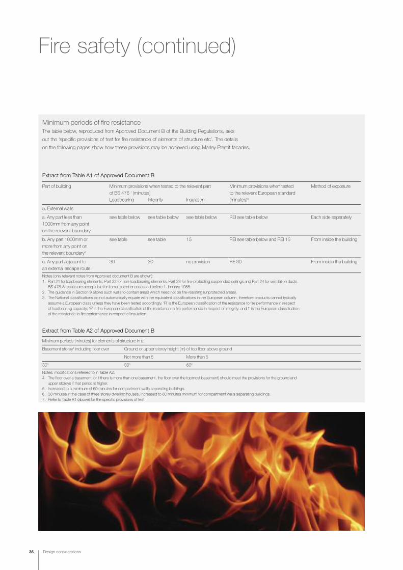
Minimum periods of fire resistance
The table below, reproduced from Approved Document B of the Building Regulations, sets
out the ‘specific provisions of test for fire resistance of elements of structure etc’. The details
on the following pages show how these provisions may be achieved using Marley Eternit facades.
Extract from Table A1 of Approved Document B
Part of building Minimum provisions when tested to the relevant part Minimum provisions when tested Method of exposure
of BS 476 1 (minutes) to the relevant European standard
Loadbearing Integrity Insulation (minutes)3
5. External walls
a. Any part less than see table below see table below see table below REI see table below Each side separately
1000mm from any point
on the relevant boundary
b. Any part 1000mm or see table see table 15 REI see table below and REI 15 From inside the building
more from any point on
the relevant boundary2
c. Any part adjacent to 30 30 no provision RE 30 From inside the building
an external escape route
Notes (only relevant notes from Approved document B are shown):1. Part 21 for loadbearing elements, Part 22 for non-loadbearing elements, Part 23 for fire-protecting suspended ceilings and Part 24 for ventilation ducts.
BS 476-8 results are acceptable for items tested or assessed before 1 January 1988.2. The guidance in Section 9 allows such walls to contain areas which need not be fire-resisting (unprotected areas).3. The National classifications do not automatically equate with the equivalent classifications in the European column, therefore products cannot typically
assume a European class unless they have been tested accordingly. ‘R’ is the European classification of the resistance to fire performance in respect of loadbearing capacity; ‘E’ is the European classification of the resistance to fire performance in respect of integrity; and ‘I’ is the European classification of the resistance to fire performance in respect of insulation.
Extract from Table A2 of Approved Document B
Minimum periods (minutes) for elements of structure in a:
Basement storey4 including floor over Ground or upper storey height (m) of top floor above ground
Not more than 5 More than 5
305 305 606
Notes: modifications referred to in Table A2:4. The floor over a basement (or if there is more than one basement, the floor over the topmost basement) should meet the provisions for the ground and
upper storeys if that period is higher.5. Increased to a minimum of 60 minutes for compartment walls separating buildings.6. 30 minutes in the case of three storey dwelling houses, increased to 60 minutes minimum for compartment walls separating buildings.7. Refer to Table A1 (above) for the specific provisions of test.

Design considerations 37
Compartmentation in facadesFor both vertical and horizontal compartmentation Promat UK offer a range
a Rainscreen Barrier solutions. The products simply fit within the Rainscreen
cavity and helps protect against the spread of fire. For further details please
contact Promat UK on 01344 381300 or e-mail [email protected].

Thermal insulation
38 Design considerations
Building RegulationsThe relevant documents are
Approved Document L1A
‘Conservation of fuel and
power in new dwellings’;
L1B ‘Conservation of fuel and
power in existing dwellings’ ;
L2A ‘Conservation of fuel and
power in new buildings other
than dwellings’ and L2B
‘Conservation of fuel and
power in existing buildings
other than dwellings’ for
England and Wales and
Section 6 ‘Energy’ (domestic
and non-domestic) for Scotland
(see separate leaflet).
The Building Regulations
prescribe high standards of
building fabric insulation for
floors, walls and roofs as well
as space heating, lighting, and
hot water controls so as to limit
the heat loss from the building .
The Part L Approved Documents have been
regularly amended over the past ten years to
reflect improvements in terms of the energy
efficiency of buildings, which are responsible for
around 40% of all CO2 emissions generated.
The 2002 revision of Part L reduced the
permitted carbon dioxide emissions by 25%
over the 1990 levels and the 2006 revision
reduced the levels further by an average of
20% for new dwellings and up to 28% for
non-dwellings. This generated an overall
improvement in excess of 40% over the 1990
levels. The latest revision which came into effect
on 1st October 2010 introduces a further 25%
reduction on the annual CO2 emission rate
relative to the 2006 standards.
ComplianceThe new requirements of the Regulations are
designed to reduce carbon emissions from new
buildings and to improve the performance of
existing buildings where new work is carried out.
Parts L1A, L1B, L2A and L2B have a single
method of compliance. This is expressed in
CO2 emissions in kg/m2/year and is calculated
by the SAP (Standard Assessment Procedure)
2009 method for dwellings and the iSBEM
model for non-dwellings or all buildings over
450m2. This involves a series of calculations
based on heat loss of elemental areas, volumes
of spaces to be heated, heating systems, solar
gain etc., for which computer software models
are available.
In terms of the external walls and claddings,
designers will no longer be able to specify
“walls to comply with Part L” on drawings or in
specifications. Products can no longer be
labelled ‘Part L compliant’, as not one element
or product can meet Part L without
consideration for all other elements in the
construction and energy use of the building.
The design process is now more complicated
as a number of assumptions have to be made
at the design stage when inputting into the SAP
or iSBEM calculations before the specification
can be finalised, to see if the building will be
compliant with Part L compared to a notional
building.
The main variables to consider are:-
• External envelope U-values for walls,
roofs and floors
• Thermal bridging details
• Ventilation strategy for ensuring fresh air
• Airtightness
• Solar gain
The following sections briefly summarise the
content of the four parts of Part L –
Part L1A - ‘New dwellings’There are five criteria where compliance must
be demonstrated for all new dwellings:
1 The predicted CO2 emission (DER) from
the proposed dwelling must not exceed the
target emission (TER) (based on the notional
dwelling*).
*The notional building model has a party
wall heat loss of zero, which means that the
targeted improvement of 25% is in addition
to any heat loss through the party wall.
2 The thermal performance of the building
fabric and performance of fixed building
services should not be worse than the
design limits set out in L1A.
3 The dwelling must have appropriate passive
control measures to limit solar gains to
reduce or eliminate the need for mechanical
cooling.
4 The performance of the ‘as built’ dwelling
should be consistent with the DER and
meet the TER.
5 Information must be provided for the
energy-efficient operation of the fixed
services in the dwelling.
The target CO2 Emission Rate (TER) for
dwellings is calculated using SAP (Standard
Assessment Procedure) 2009 for a ‘notional’
dwelling of the same size and shape as the
‘actual’ dwelling (based on set construction
rules). The emission rate for the notional
dwelling is calculated using a fixed set of values
for the fabric heat loss, building services and
type of fuel. The TER rate is equivalent to a gas
heated dwelling insulated to 2002 standards.

Design considerations 39
Part L2B – ‘Existing non-dwellings’This applies to extensions and subsequent fit
out works, change of use, material changes,
work on controlled services etc. New building
fit outs for existing buildings should comply
with Part L2B.
Part L 2010 introduces ‘Consequential
Improvements’ which may in some situations
require the upgrading of windows, boilers,
air-conditioning and lighting as well as the
inclusion of energy metering systems.
For all parts
Where possible, LZC (Low and Zero Carbon)
systems should be installed.
Unit energy costs for each fuel type are detailed
in the Approved Documents and should be
used for assessing the feasibility of various
improvements.
Airtightness/air leakagePart L 2010 provides requirements for buildings
to be tested for air leakage once completed.
Testing is carried out using pressurised fans
and consultants, to ensure that as well as the
theoretical heat loss calculations, the building is
not leaky and wasting energy through gaps and
cracks due to construction methods.
Workmanship and detailing on site to ensure
that a permitted air leakage of 10m3/hour/m2
@ 50 Pa is not exceeded when tested.
The building designer has to make an
assumption of what the level of airtightness
he can achieve from his building at the design
stage. This is inputted into the calculation for
his heat loss/SAP calculations. Should the
building be found to be higher in terms of air
leakage, then remedial measures must be
taken to ensure the building meets the required
design value.
Part L1B – ‘Existing dwellings’This includes most extensions, material
changes of use, material alterations, provision of
controlled fittings and services and provision or
renovation of a thermal element. The
recommended maximum U-values for an
extension may be varied on condition that it is
no worse overall than a similar extension built
to the standards and that the defined maximum
U-values are not exceeded.
SAP 2009 can be used to demonstrate that
CO2 emissions from a dwelling plus an
extension taken together are no worse than that
of the dwelling complying with regulations plus a
separate extension complying with regulations.
This process may involve improvements to the
existing thermal elements, such as walls, roofs
and floors, which must comply with Part L1B
standards.
Where more than 25% of the surface area of a
thermal element is renovated, the thermal
performance of the whole element should be
improved to achieve either the standard for
replacement thermal elements or as a minimum,
the standard that is practicable and cost
effective within a simple payback of 15 years.
Part L2A - ‘New non-dwellings’There are 5 key criteria for compliance:
1 CO2 emissions must be less than target
value (TER). A notional building is used for
calculating the TER referred to as the
‘aggregate 25% approach’. A design-stage
TER/BER calculation is also required as a
means of helping to improve compliance.
2 The thermal performance of building fabric
and services (heating, hot water and fixed
lighting) should achieve reasonable overall
standards of energy efficiency.
3 The building must have appropriate passive
control measures to limit solar gains.
4 The performance of the building, as built,
should be consistent with the prediction
made in the BER.
5 The necessary provisions for enabling
energy-efficient operation should be put
in place.
Design considerationsThere are a number of factors to consider when
designing buildings that are to meet the new
Part L requirements. These will involve the types
of windows, doors, rooflights, solar gain, frame
factor, air infiltration, U-Values, type of glass,
total area and aspect of the dwelling. The
designer will also be required to consider the
heating system, the impact of any mechanical
ventilation systems, along with the controls,
and any low and zero carbon technologies,
e.g. solar PV, wind power. Credits will be
achieved for the use of ‘low carbon’ and energy
saving products, which in many cases will be
the preferred route to compliance. This will
involve an assessment of the whole building
performance and not just each individual value.
In order to improve the quality of design details,
a set of ‘Accredited Construction Details’ have
been published to accompany the new Part L.
These are updated versions of 2002 Thermal
‘Robust Details’, and if approved over
specifications could limit the requirement for
on-site testing.
Attention is given to the provision of suitable
insulation to prevent heat loss and cold bridges
in roof construction. Guidance measures to
prevent moisture ingress, condensation and air
leakage are incorporated into the construction
details for walls, floors and roofs, with particular
attention being given to the junctions of walls to
floors and walls to roofs.
As insulation levels increase so does the
potential risk of condensation, and so designers
should consider the recommendations with
regard to the prevention of condensation in ‘cold’
roof voids contained in BS 5250: 2002 AMD 1,
which is also referenced in Approved Document
C of the Building Regulations.

1
3 4 5 6 7 8
2
140mm Knauf Insulation FrameTherm 35 4
Plasterboard 1
Timber stud 3
Fibre cement sheathing 5
Knauf Insulation Breatheline 2
38 x 50mm timber batten 7
Marley Eternitfacade material 8
Air gap 6
40 Design considerations
Blockwork wall• Marley Eternit facade material
• 38 x 50mm and 38 x 100mm
timber battens
• Counterbattens 50 x 50mm
• Single skin 440 x 215mm
Aircrete blocks
• 50mm PIR insulation
Notes• Internal wall should be 12.5mm plasterboard on dabs.
• Dew point calculations should always be undertaken to determine dew point and whether a breather membraneis required.
Thermal design detailsnew structures – housing
0.25u-value
Timber frame wall• Marley Eternit facade material
• 38 x 50mm timber battens
• 140 x 60mm timber studs
• 140mm Knauf FrameTherm
35 insulation between studs
• Knauf Insulation Breatheline vapour control
layer between plasterboard and timber studs
Note• Dew point calculations should always be undertaken to
determine dew point and whether a breather membraneis required.
0.29u-value
12.5mm Plasterboardon dabs 1
3 6 8
50mm PIRinsulationpartial fill 3
215mm TurboAircrete blocks 2
38 x 50mm batten 5
38 x 100mm batten 6
Marley Eternitfacade material 8
Air gap 7
50 x 50mm counterbatten 4
1
2 3 5 4 6 7 8

1
3 4 5 6 7
2
Thermostop pad 2
Ventispan system 3
Precast concrete wall 1
130mm PIR insulation 4
Marley Eternit facade material 7
8-10 joint 6
30mm min. air gap 5
Design considerations 41
Thermal design detailsnew structures – commercial, education or healthcare
Lightweight steel frame• Marley Eternit facade material
• 125mm stone mineral wool
• Ventisol or similar framing system
• Bluclad cement board
• 100 x 75mm ‘C’ sections
• 90mm glass mineral wool
• Vapour control layer
• Internal wall should be 2 layers of 12.5mm
plasterboard on dabs
Note• Dew point calculations should always be undertaken to
determine dew point and whether a breather membraneis required.
0.23u-value
Concrete wall construction• Marley Eternit facade material
• Ventispan framing system
• 130mm PIR insulation
• Structural concrete slab
• Steel framing infill system (between floors)
Notes• A very wide variety of internal wall finishing options
are available, many of which will incorporate further layers of insulation.
• Dew point calculations should always be undertaken to determine dew point and whether a breather membraneis required.
0.14u-value
1 2 3 4 5
6 97 8 10 11
2 layers ofplasterboard 1
Thermostop pad 7
6mm min.air gap 9
30mm gap 10
90mm insulation 3
Vapour control layer 2
120mm insulation 6
100 x 75mm ‘C’ Sections 4
Aluminium frame fixing system 8
Bluclad cement board 5
Marley Eternitfacade material 11
Brickwork wall• Marley Eternit facade material
• Ventisol fixing system
• Air gap (min. 30mm)
• 80mm Rockwool Rainscreen Duo-slab
mineral wool
• 9” solid brick wall (laid as headers
and stretchers)
Notes• 9” solid walls are common in pre-1930 house construction and
the brick bonding can be in a number of configurations
• U-values of these types of wall are typically 1.9-2.2 W/m2K
• Other fixing systems can also be used
• Greater (or lesser) depths of insulant can be accommodated
• Dew point calculations should always be undertaken to determine dew point and whether a breather membrane is required.
42 Design considerations
9” solid brick wallheaders and stretchers 1
80mm Rockwool Rainscreen Duo-slab mineral wool 3
Marley Eternit facade material 5
Air gap 4
Fixing system 2
1
2 3 4
5
Brickwork 3
Blockwork 1
80mm Rockwool Rainscreen Duo-slab mineral wool 5
Marley Eternit facade material 7
Air gap 6
Fixing system 4
Empty cavity 2
Thermal design detailsupgrading existing structures and overcladding
upgrade
2.00u-value
0.35u-value
Block and brickwork wall• Marley Eternit facade material
• Ventisol fixing system
• Air gap (min. 30mm)
• 80mm Rockwool Rainscreen
Duo-slab mineral wool
• Brick outer skin
• Cavity not insulated
• Brick inner skin
Notes• U-values of these types of un-insulated wall are typically 1.0-1.6 W/m2k
• Other fixing systems can also be used
• Greater (or lesser) depths of insulant can be accommodated
• Dew point calculations should always be undertaken to determine dew point and whether a breather membrane is required.
upgrade
1.50u-value
0.33u-value
1
2 3 4 5 6 7

Design considerations 43
EQUITONE [natura] , Barking
Foyer, B
arking

UV-resistance
creativelight weight
finishimpact resistance
performance
aesthetics
contemporary
44 Facade material

fibre cement
colour
beautiful facades
46-51 EQUITONE [natura]
52-57 EQUITONE [tectiva]
58-63 EQUITONE [pictura]
64-69 EQUITONE [textura]
clean lines
textureinspirational
Facade material
Facade material 45
A+ rating

46 Facade material
[natura]
Advantages• Through coloured fibre cement
• Texture of the fibres show through
• Tactile, smooth surface
• Secret fix system
• Available with factory applied anti-graffiti coating
CERTIFICATE No 06/4355
EQUITONE [natura] through coloured fibre cement material
offers specifiers a sustainable and low maintenance facade
that combines excellent aesthetics with durability and
impact resistance: qualities that will enhance any new
build project or equally, improve and upgrade an existing
building as an overclad solution.
Available in a range of colours and finishes including an
anti-graffiti coating, and both mechanical and secret fix
options, EQUITONE [natura] gives specifiers the full creative
scope of modern cladding systems with the performance
levels contemporary buildings demand.
A+Marley E
ternit's
fibre cement clad
ding
can achieve an
A+ rating
as defined in th
e BRE
Green Guide to
Specification*
* Fibre Cement Cladding based on generic rating for autoclaved fibre cement single sheet (Element ref: 80623042, 806230422, 806230447, 806230450)

Facade material 47
EQUITONE [natura] , University Cam
pus, York

48 Facade material
Properties (air dry)
Density 1650kg/m3
Bending strength:
Longitudinal 26N/mm2
Transverse 17N/mm2
Modulus of elasticity 15,000N/mm2
Porosity 20%
Hydric movement 1mm/m
Co-efficient of linear
expansion 10 x 10-6m/mK
Thermal conductivity 0.4W/mK
Frost resistance Fully frost resistant
Reaction to fire:
EN 13501-1 A2-s1, d0
Dimensions
Panel thickness 8/12mm
Sheet sizes* 2500 x 1250mm
3100 x 1250mm
See pages 50-51 for colour range
Nominal weight 8mm: 13.6kg/m2
12mm: 20.4kg/m2
Tolerance on thickness ±10%
* These are the maximum panel sizes after trimming
by a fabricator.
Standards
The technical properties of EQUITONE [natura]
sheets are in accordance with the prescriptions
of BS EN 12467:2004, Category A, Class 3.
Manufacture
EQUITONE [natura] has been developed for
external cladding applications and is a coloured
fibre cement board which allows the fibres to
show through, giving a unique surface
appearance.
Please note, traces of manufacture and colour
variation are to be expected.
Availability
The most popular colours are usually available
on short lead times. All other colours are made
to order and will be subject to longer lead times.
EQUITONE [natura] , Private Hou
se, U
trech
t
EQUITONE [natura] , University Cam
pus Suffolk, Ips
wich Marina
[natura] technical data

Facade material 49
Other fixing systems and design detailingEQUITONE [natura] can be fixed using the systems below.
Timber battens (90-93) Omega and Zeds (94-99) Ventisol (100-103)
Ventispan (104-107) Structural bonding (109-111) Mechanical secret fix (112-113)
‡ Applicationinstructions
Marley Eternit offer a full range of
Application Instructions for their fixing
systems, setting out details and
installation data.
Please contact the Technical Advisory
Service for further information on
01283 722588.
*25-100
75-100
600 600
600
Hole sizes
Pre-drilled holes in the panels
should be 6mm. For EQUITONE
[natura] panels with Pro coating,
please contact the Technical
Advisory Service for more
information.
Notes1 In all cases it is important to have the
corner fixings staggered at unequal spacings from the two edges.
2 A minimum 8-10mm gap should be allowed between all panels.
Sleeve – for
EQUITONE
[natura] Pro
coating only
15mm
35mm
Finishes
EQUITONE [natura] is supplied with unfinished
edges and must be cut by a specialist
fabricator. Cut edges of EQUITONE [natura]
must be sealed with Luko solution. Please
contact Marley Eternit for more information.
Fixing overviewIn facade applications, EQUITONE [natura] has
a number of fixing options. Please refer to
pages 88-115 for fixing system information.
Batten sizing
At panel joints: min 100 x 38mm.
At intermediate points: min 50 x 38mm.
Batten rail spacing
Maximum batten centres 600mm.
For 1.5kN/m2 wind load.
Bonding for secret fixing
If EQUITONE [natura] is to be glued, the
adhesive must be used in accordance with the
application guidelines and guarantee conditions
of the adhesive supplier (SikaTack-Panel).
Further information is available from Marley
Eternit.
Screwing
Stainless steel screws with mushroom
head and torx drive.
Screws can be used in pre-drilled holes only.
• 5.5 x 35mm for 8mm thickness.
• Screws must be used in conjunction with
top hat sleeve.
See diagram, right.
Blind riveting
Aluminium rivets and associated cylindrical
spacer sleeve in 9.5 mm holes.
Aluminium rivets:
• 4 x 18 – K15mm for 8mm thickness.
• Special rivet-setting tool must be used
Mechanical secret fix
In facade applications where a smooth
unbroken surface is required, Marley Eternit
offer a concealed mechanical fixing system.
Hangers are fixed to the rear face of 12mm
thick EQUITONE [natura] panels. The hangers
hook onto horizontal rails, which, in turn, are
fixed to vertical rails.

50 Facade material
EQUITONE [natura] is offered in a range of colours
to meet both aesthetic and performance needs.
EQUITONE [natura] allows the texture of the fibres to show through. This,combined with the extensive colour choice, offers the designer a high degree of visual flexibility.
EQUITONE [natura] is also available with a UV ‘Pro’ coating to provide excellentgraffiti resistance characteristics.
Slate (N071)
Anthracite (N251)
Cinereous (N072)
Sage (N572)
Silver Grey (N283)
Grass Green (N573)
Soft Green (N592)
Mineral Grey (N282)
[natura] colour range
Charcoal (N073)

Facade material 51
Cool Grey (N292)
Azure (N473) Natural Grey (N250)
Beach Stone (N891)
Magma (N372)
Ruby (N359)
Cream White (N154)
Muted Stone (N271)
Bluestone (N491)
Sepia (N972)
Earthy (N973)
Clay (N373)
Morning Mist (N191)

52 Facade material
EQUITONE [tectiva] is a through coloured fibre cement
material that offers elegant shades of natural colour
providing a unique aesthetic effect.
EQUITONE [tectiva] is characterised by the fine
sanded lines and naturally occurring hues within the
material. These enhance the natural matt appearance
which comes to life with the effects of light and shade
to provide a distinctive and beautiful facade.
A+Marley E
ternit's
fibre cement clad
ding
can achieve an
A+ rating
as defined in th
e BRE
Green Guide to
Specification*
Advantages
• Through coloured fibre cement
• Unique and natural appearance
• Subtle shades
* Fibre Cement Cladding based on generic rating for autoclaved fibre cement single sheet (Element ref: 80623042, 806230422, 806230447, 806230450)
[tectiva]

Facade material 53
EQUITONE [tectiva], Passivhaus, Bland
en, Belgium

54 Facade material
EQUITONE [tectiva], Office
Building, Tem
se, Belgium
Standards
The technical properties of EQUITONE [tectiva]
sheets are in accordance with the prescriptions
of BS EN 12467:2004, Category A, Class 4.
Manufacture
EQUITONE [tectiva] has been developed for
external cladding applications and is a through
coloured fibre cement board with a fine sanded
textural finish.
Please note, traces of manufacture and colour
variation are to be expected.
Availability
The most popular colours are usually available
on short lead times. All other colours are made
to order and will be subject to longer lead times.
Properties (air dry)
Density 1580kg/m3
Bending strength:
Longitudinal 32N/mm2
Transverse 22N/mm2
Modulus of elasticity 14,000N/mm2
Porosity < 25%
Hydric movement 1.6mm/m
Co-efficient of linear
expansion <0.01mm/mK
Thermal conductivity 0.39W/mK
Frost resistance Fully frost resistant
Reaction to fire:
EN 13501-1 A2-s1, d0
Dimensions
Panel thickness 8mm
Sheet sizes 2500 x 1220mm
3050 x 1220mm
Nominal weight 8mm: 14.9kg/m2
Tolerance on thickness ±0.5mm
[tectiva] technical data

Ventisol fixing system4.8 mm dia
16 mm 7.5 mmEQUITONE [texctiva]
Astro rivet Astro rivet spacer
Plan section showing EQUITONE [tectiva] panels fixed to aluminium section with Astro rivet fixing system
Facade material 55
Other�fixing�systems�and�design�detailingEQUITONE [tectiva] can be fixed using the systems below.
Timber battens (90-93) Omega and Zeds (94-99) Ventisol (100-103)
Ventispan (104-107) Structural bonding (109-111) Mechanical secret fix (112-113)
9.0
5.0
16
20
4.8
Astro rivet Self-adhesive tape
Fixing overviewIn facade applications, EQUITONE [tectiva] can
be screwed to vertical timber battens or riveted
to an aluminium sub-frame. Please refer to
pages 88-115 for fixing system information.
Batten sizing
At panel joints: min 100 x 38mm.
At intermediate points: min 50 x 38mm.
Batten rail spacing
Maximum batten centres 600mm.
For 1.5kN/m2 wind load.
Bonding for secret fixing
If EQUITONE [tectiva] is to be glued, the
adhesive must be used in accordance with
the application guidelines and guarantee
conditions of the adhesive supplier
(SikaTack-Panel). Further information is
available from Marley Eternit.
Screwing
Stainless steel screws with mushroom
head and torx drive.
Screws can be used in pre-drilled holes only.
• 4.8 x 38mm for 8mm thickness.
Blind riveting
8.3mm holes for fixed point and 11mm
holes for sliding point.
Aluminium rivets:
• 4.8 x 20 – K15mm for 8mm thickness.
Astro rivet fixing system
This is a bespoke fixing system for EQUITONE
[tectiva] allowing the panels to be simply, rapidly
and securely fixed to aluminium or steel support
systems. The installation procedure is as follows:
1 Fix the self-adhesive strips to the vertical
metal profiles.
2 Pre-drill the EQUITONE [tectiva] panels
according to the correct fixing pattern and
using the correct size drill bits.
3 Position each panel correctly against the
vertical metal profiles and hold it steady.
4 Drill through the F alignment hole and fix
the Astro rivet.
5 Drill the G-holes and fix the remaining
Astro rivets.
‡ Applicationinstructions
Marley Eternit offer a full range of Application
Instructions for their fixing systems, setting
out details and installation data.
Please contact the Technical Advisory
Service for further information on 01283
722588.

Chalk (TE90)
56 Facade material
EQUITONE [tectiva]* is available in nine organic through colours
where the pigment is held within the mass of the board to provide
a timeless colour that fits perfectly into contemporary architecture.
* Naturally occurring white flecks may be visible which add to the aesthetics
of the material
Linen (TE10)
Pebble (TE20)
Calico (TE00)
[tectiva] colour range
Mineral Black (TE80)

Facade material 57
Pistachio (TE50)
Sandstorm (TE30)
Hessian (TE60)
Sahara (TE40)

58 Facade material
EQUITONE [pictura] incorporates an additional surface
treatment onto the fibre cement material. The main
characteristic of this treatment is the hard, smooth, silky
matt surface.
The UV cured top layer offers good protection against
many types of staining and mechanical damage during
construction.
Whilst the EQUITONE [pictura] surface is smooth and
easily cleanable, it also provides protection against
graffiti produced by common aerosol and other paints.
Graffiti can be eliminated with common graffiti removers.
Advantages
• Smooth and silky finish
• Anti-graffiti protection as standard
• Available in 15 bold colours
CERTIFICATE No 06/4355
A+Marley E
ternit's
fibre cement clad
ding
can achieve an
A+ rating
as defined in th
e BRE
Green Guide to
Specification*
* Fibre Cement Cladding based on generic rating for autoclaved fibre cement single sheet (Element ref: 80623042, 806230422, 806230447, 806230450)
[pictura]

Facade material 59
EQUITONE [pictura] , Rec
ord Bank, Dinant, Belgium

60 Facade material
AvailabilityThe most popular colours are usually available
on short lead times. All other colours are made
to order and will be subject to longer lead times.
Dimensions
Nominal thickness 8mm/12mm
Sheet sizes* 2500 x 1250mm3100 x 1250mm
Nominal weight: 8mm: 15.4 kg/m2
12mm: 22.8 kg/m2
Tolerance on thickness ±10%
* These are the maximum sheet sizes available after
trimming by a fabricator.
Properties (air dry)
Density 1650 kg/m3
Bending strength:Longitudinal 26N/mm2
Transverse 17N/mm2
Modulus of elasticity 15,000N/mm2
Hydric movement 1.0mm/m
Co-efficient of linear
expansion 10 x 10-6m/mK
Thermal conductivity 0.6 W/mK
Frost resistance Fully frost resistant
Reaction to fire:EN 13501-1 A2-s1, d0
Temperature – durability rated up to 80 °C
StandardsThe technical properties of EQUITONE [pictura]
sheets are in accordance with the prescriptions
of BS EN 12467: 2004, Category A, Class 3.
The panels are manufactured to ISO 9001
and ISO 14001.
ManufactureEQUITONE [pictura] is produced on a Hatschek
machine and is pressed and air-dried. The
surface is smooth, not glossy, with an acrylic
coating and a UV hardened top layer, to
produce a strong impact and dirt resistant
finish. This finish gives a hard surface, offering
‘anti graffiti’ protection from most kinds of paint.
EQUITONE [pictura], Bou
rnside
Sch
ool, Che
ltenh
am
EQUITONE [pictura], Darlington
Hospital
Before
[pictura] technical data

Facade material 61
*25-100
75-100
600 600
600
Hole sizes
Pre-drilled holes in the panels
should be 7mm.
Notes1 In all cases it is important to have the
corner fixings staggered at unequal spacings from the two edges.
2 A minimum 8-10mm gap should be allowed between all panels.
Sleeve
15mm
35mm
Finishes
EQUITONE [pictura] is supplied with unfinished
edges and must be cut by a specialist
fabricator. Cut edges of EQUITONE [pictura]
must be sealed with Luko solution. Please
contact Marley Eternit for more information.
Fixing overviewIn facade applications, EQUITONE [pictura] can
be screwed to vertical timber battens or riveted
to an aluminium sub-frame. Please refer to
pages 88-115 for fixing system information.
Batten sizing
At panel joints: min 100 x 38mm.
At intermediate points: min 50 x 38mm.
Batten rail spacing
Maximum batten centres 600mm.
For 1.5kN/m2 wind load.
Bonding for secret fixing
If EQUITONE [pictura] is to be glued, the
adhesive must be used in accordance with the
application guidelines and guarantee conditions
of the adhesive supplier (SikaTack-Panel).
Further information is available from Marley
Eternit.
Screwing
Stainless steel screws with mushroom
head and torx drive.
Screws can be used in pre-drilled holes only.
• 5.5 x 40mm for 8mm thickness,
7mm diameter.
• Screws must be used in conjunction with
top hat sleeve.
See diagram, right.
Blind riveting
Aluminium rivets and associated cylindrical
spacer sleeve in 9.5 mm holes.
Aluminium rivets:
• 4 x 18 – K15mm for 8mm thickness.
• Special rivet-setting tool must be used
Mechanical secret fix
In facade applications where a smooth
unbroken surface is required, Marley Eternit
offer a concealed mechanical fixing system.
Hangers are fixed to the rear face of 12mm
thick EQUITONE [pictura] panels. The hangers
hook onto horizontal rails, which, in turn, are
fixed to vertical rails.
‡ Applicationinstructions
Marley Eternit offer a full range of Application
Instructions for their fixing systems, setting
out details and installation data.
Please contact the Technical Advisory
Service for further information on 01283
722588.
Other fixing systems and design detailingEQUITONE [pictura] can be fixed using the systems below.
Timber battens (90-93) Omega and Zeds (94-99) Ventisol (100-103)
Ventispan (104-107) Structural bonding (109-111) Mechanical secret fix (112-113)

62 Facade material
Olive (PU542)
Liquid Blue (PU441) Khaki (PU543)
Camel (PU943)
Chocolate (PU941)
Sunset (PU741)
Volcanic Red (PU341)
Deep Green (PU541)
[pictura] colour range

Facade material 63
Roman Stone (PU842) Parchment (PU841)
Porcelain (PU141)
Gunmetal Grey (PU241)
Flint (PU242)
Moonstone (PU243)
Matt Black (PU041)

64 Facade material
EQUITONE [textura] combines vivid colour, texture
and toughness to create distinct and unique designs.
With a highly glazed, granular finish available in any
factory-approved RAL colour, it is impact resistant
yet strong, light in weight and easy to use.
Its performance pedigree is second to none, complying
with British and European Standards with regard to fire
resistance and spread of flame.
EQUITONE [textura] can be surface-fixed, or secured
with specially designed, concealed fixings.
Advantages• Available in any factory-approved RAL colour
(subject to minimum order)
• Granular finish
• Vibrant colours as standard
CERTIFICATE No 06/4355
A+Marley E
ternit's
fibre cement clad
ding
can achieve an
A+ rating
as defined in th
e BRE
Green Guide to
Specification*
* Fibre Cement Cladding based on generic rating for autoclaved fibre cement single sheet (Element ref: 80623042, 806230422, 806230447, 806230450)
[textura]

Facade material 65
EQUITONE [textura], Art College
, Manch
ester

66 Facade material
Aluminium rail
8mmEQUITONE
[textura]
4.0mm dia rivet
Fixed point sleeve
4.1mm hole in rail
9.5mm hole in panel
Marley Eternit rivet 4x18-K15mm
Screw fixing to timber battens
EQUITONE [textura] is also suitable for surface
fixing. Marley Eternit offer colour matched rivets
and screws (screws shown below).
Minimum batten sizes:
• 100 x 38mm at panel joints
• 50 x 38mm for intermediate positions
Screws: 5.5 x 35mm
EPS 30joint strip
≥ 25mm
38m
m
Rivet fixing to aluminium rails
35mm 15 mm
4mm
15mm
18mm
EQUITONE [textura] colour matched screw
EQUITONE [textura] colour matched rivet
StandardsThe technical properties of EQUITONE [textura]
sheets are in accordance with the prescriptions
of BS EN 12467:2004, Category A, Class 3.
ManufactureEQUITONE [textura] has been developed for
external cladding applications and is a fully
compressed fibre cement board.
AvailabilityThe most popular colours are usually available
on short lead times. All other colours are made
to order and will be subject to longer lead
times.
Factory-approved RAL colours
Our production facility is able to produce a
wide range of RAL colours. For specific project
requirements check availability with the
Technical Advisory Service 01283 722588.
Properties (air dry)
Density 1650kg/m3
Bending strength:
Longitudinal 24N/mm2
Transverse 17N/mm2
Modulus of elasticity 15,000N/mm2
Hydric movement 0.5mm/m
Co-efficient of linear
expansion 10 x 10-6m/mK
Thermal conductivity 0.4W/mK
Frost resistance Fully frost resistant
Reaction to fire:
EN 13501-1 A2-s1, d0
Dimensions
Nominal thickness 8/12 mm
Sheet sizes* 2500 x 1250mm
3100 x 1250mm
3100 x 1500mm
Nominal weight 8 mm: 15.4kg/m2
12 mm: 22.8kg/m2
Tolerance on thickness ±10%
* These are the maximum panel sizes after trimming by a fabricator.
[textura] technical data
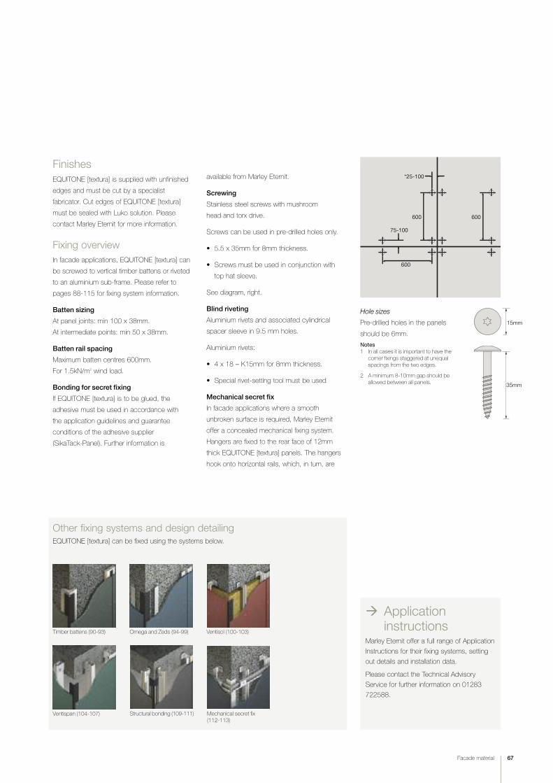
Facade material 67
Other fixing systems and design detailingEQUITONE [textura] can be fixed using the systems below.
‡ Applicationinstructions
Marley Eternit offer a full range of Application
Instructions for their fixing systems, setting
out details and installation data.
Please contact the Technical Advisory
Service for further information on 01283
722588.
Timber battens (90-93) Omega and Zeds (94-99) Ventisol (100-103)
Ventispan (104-107) Structural bonding (109-111) Mechanical secret fix (112-113)
*25-100
75-100
600 600
600
Hole sizes
Pre-drilled holes in the panels
should be 6mm.
Notes1 In all cases it is important to have the
corner fixings staggered at unequal spacings from the two edges.
2 A minimum 8-10mm gap should be allowed between all panels.
15mm
35mm
Finishes
EQUITONE [textura] is supplied with unfinished
edges and must be cut by a specialist
fabricator. Cut edges of EQUITONE [textura]
must be sealed with Luko solution. Please
contact Marley Eternit for more information.
Fixing overview
In facade applications, EQUITONE [textura] can
be screwed to vertical timber battens or riveted
to an aluminium sub-frame. Please refer to
pages 88-115 for fixing system information.
Batten sizing
At panel joints: min 100 x 38mm.
At intermediate points: min 50 x 38mm.
Batten rail spacing
Maximum batten centres 600mm.
For 1.5kN/m2 wind load.
Bonding for secret fixing
If EQUITONE [textura] is to be glued, the
adhesive must be used in accordance with
the application guidelines and guarantee
conditions of the adhesive supplier
(SikaTack-Panel). Further information is
available from Marley Eternit.
Screwing
Stainless steel screws with mushroom
head and torx drive.
Screws can be used in pre-drilled holes only.
• 5.5 x 35mm for 8mm thickness.
• Screws must be used in conjunction with
top hat sleeve.
See diagram, right.
Blind riveting
Aluminium rivets and associated cylindrical
spacer sleeve in 9.5 mm holes.
Aluminium rivets:
• 4 x 18 – K15mm for 8mm thickness.
• Special rivet-setting tool must be used
Mechanical secret fix
In facade applications where a smooth
unbroken surface is required, Marley Eternit
offer a concealed mechanical fixing system.
Hangers are fixed to the rear face of 12mm
thick EQUITONE [textura] panels. The hangers
hook onto horizontal rails, which, in turn, are

68 Facade material
Any factory-approved RAL colour is
available subject to minimum quantity.
Colour codesPlease note:
TA prefix indicates Anthracite core.
TG prefix indicates Grey core.
Factory-approved RAL coloursOur production facility is able to produce a
wide range of RAL colours.
For specific project requirements check
availability with the Technical Advisory Service
on 01283 722588.
Metal Grey (TG404)
Onyx (TA001) Natural Titanium (TA207)
Arctic (TG102)
Graphite (TG206)
[textura] colour range
Pearl (TG205)
Pacific White (TG504)

Deep Red (TA304)
Egyptian Blue (TA405)
Facade material 69
Buttermilk (TG601)
Straw (TG803) Celestial Blue (TG403)Sand (TG602)
Ember (TA701)
Sienna Red (TA305)

70 Facade material
profiled sheetin
colour
finishsoffits
facade materials
render backing
tile hanging

Facade material 71
fibre cement
ngweatherboarding
72-73 Operal
74-77 Cedral Weatherboard
78-81 Bluclad
clean lines
practical
Other Marley Eternitfacade materials
operal
82-83 Profiled Sheeting
84-85 Vertical tile hanging

72 Facade material
Operal
38mm
1
12mm
Operal is ideal for decorative and protective
soffits and fascias
Operal is a cost effective, easy to fix material with a range of 23 colours,
that complement the Cedral Weatherboard range (pages 74-77), to
provide practical and aesthetic benefits to the designer requiring cost
effective and attractive external cladding solutions.
StandardsThe technical properties of Operal sheets are in accordance with the
prescriptions of BS EN 12467:2004, Category A, Class 3.
ApplicationsOperal is ideal for soffits and fascias.
ManufactureOperal is an autoclaved fibre cement material which is manufactured from
a mixture of cement, organic fibres, fillers and water.
Touch up paintTouch up paint is available in 0.5 litre quantities.
Dimensions
Sheet sizes* 3050 x 1220mm
2500 x 1220mm
Nominal thickness 9mm
Nominal weight 13.0kg/m2
Tolerance on thickness ±10%
Ope
ral, Beverlo, Belgium
Ope
ral, Beverlo, Belgium
*Supplied in large format modules for cutting to size.
Fixing overviewFor small applications
(e.g. fascias, soffits), the
AvailabilityThe most popular colours are usually available on short lead times. All
other colours are made to order and will be subject to longer lead times.
EPS 30joint strip
≥ 20mm
38m
m
Operal colour matched screw
Advantages• Lightweight and easy to fix
• Easy to work on site
• Fire classifications A2-s1, d0 to EN 13501-1
• Can achieve an A+ rating in the BRE’s Green Guide to Specification*
• BBA Certificate No. 06/4355
* Based on generic rating for autoclaved fibre cement single sheet(Element ref. 80623042, 806230422, 806230447, 806230450).

Facade material 73
Other systems and design detailingFor further details on fixing using timber battens, see pages 90-93.
Application InstructionsMarley Eternit offer a full range of Application Instructions for their fixing
systems, setting out detailed design and installation data.
Please contact the Technical Advisory Service for further information
on 01283 722588.
Ope
ral, Grim
bergen
, Belgium
‡ Moresamples Tel 01283 722588
web marleyeternit.co.uk/facades
literature Cedral Weatherboard and Operal brochure
OP01 White OP02 Beige OP03 Grey Brown OP04 Dark Brown OP05 Grey OP06 Grey Green
OP07 Cream White OP08 Sand Yellow OP09 Ochre OP10 Blue Grey OP11 Beige Yellow OP12 Lavender Blue
OP13 Lilac Blue OP14 Atlas Brown OP15 Dark Grey OP16 Cevennes Green OP17 Oriental Green
OP30 Brown OP31 Pine Green OP32 Orange Brown OP33 Red OP50 Black
OP18 Slate Grey

Cedral Weatherboard
74 Facade material
Fibre cement Cedral Weatherboard is the
ideal low maintenance, rot free alternative to
traditional timber weatherboarding.
With the visual appeal of natural timber, yet simple to install and resistant
to rot, Cedral Weatherboard is an attractive low maintenance alternative
to PVCu.
Cedral Weatherboard can be supplied in a range of 23 factory applied
solid colours and 4 woodstain finishes, or in a natural finish for on-site
painting.
Our comprehensive colour range provides an aesthetic option to suit
many project requirements.
Installing Cedral WeatherboardEach plank must be fixed at least once to every support. The end of every
plank must also coincide with a support. Where specified, install vapour
barrier or breather membrane over the wall or framework behind the timber
studs. Installation begins at the bottom of the facade, where a start profile
is fixed first. This is overlapped by the first plank, which starts the layering
of the planks. Allow at least 150mm between bottom edge of
Weatherboard and the ground. Fixing is done through the upper edges.
There is no side overlap, the strips being simply loose butted against one
another, and the joint must coincide with a timber support.
A strip of black polyethylene soaker should be applied under the vertical
joints to protect the batten.
For other applications; vertically, laid flat or ship lapped, please contact
Marley Eternit’s Technical Advisory Service
Battens for Cedral Weatherboard
Cedral Weatherboard needs to be fixed to vertical timber battens
(preservative treated and planed on 2 sides) of at least 50mm wide
spaced at a maximum of 600mm across the elevation. The Cedral
Weatherboard should be fixed to at least three battens; if it is only fixed
to two then the batten spacing should be reduced to 400mm.
Ced
ral W
eatherbo
ard, Cutem
bourg Sch
ool, Th
e Nethe
rland
s
Advantages of Cedral Weatherboard
• Excellent aesthetics
• Resistant to rot, immune to attack by pests and insects
• Stands up to the harshest weather conditions
• No routine maintenance required
• Easy to install
• Range of complementary aluminium trims available
• Use in the same way as wood
• Fire classifications A2-s1, d0 to EN 13501-1
• Ideal for use where traditional timber boards might be considered especially for facades and window and door surrounds
• Can achieve an A+ rating in the BRE’s Green Guide to Specification*
• BBA Certificate No. 06/4299
* Based on generic rating for autoclaved fibre cement (calcium silicate) cladding(Element ref. 806220701, 806220675, 806220676).

Facade material 75
Ced
ral W
eatherbo
ard, East B
each
Roa
d, Selsey, W
est S
ussex
Ced
ral W
eatherbo
ard, Rep
ton Park, Ashford, Ken
t
38 x 50mmtimber batten
Nail or screw
Start profile
Cedral Weatherboard
30mm
30mm
30mm
150mm 21mm
Perforated closure10mm
60mm
20mm
Main structure
Base of cladding
50 x 38mm min. timber battens600mm c/c max. fixed back to structure
Main structure
10mm Cedral Weatherboard
Metal flashingby others
Start profile
30mm lap
30mm
30mm60mm
Nail or screw
Perforated closure
Plinth detail

76 Facade material
Cedral Weatherboardcolour range
C12 Lavender Blue
C11 Beige Yellow
C13 Lilac Blue
C14 Atlas Brown
C16 Cevennes GreenC10 Blue Grey
C15 Dark Grey
C01 White
C07 Cream White
C08 Sand Yellow
C06 Grey Green
C02 Beige
C05 Grey
C03 Grey Brown
C04 Dark Brown
C09 Ochre

Facade material 77
C33 Red
C50 Black
C32 Orange Brown
C30 Brown
C31 Pine Green C17 Oriental Green
C00 Natural
CL102 Pine
Woodstain colours
CL103 Ebony CL104 Light Oak CL105 Dark Oak
Cedral Weatherboard is also available in a range
of woodstain shades to simulate the colour and
texture of a variety of timber stocks.
* Due to the transparent coating, it is not recommended to install Cedral Weatherboard woodstain colours vertically.
C18 Slate Grey

78 Facade material
Bluclad
Bluclad is the ideal backer for render to use in
weather-exposed locations.
A flat, vapour-permeable Class 0 building board with
outstanding dimensional stability, Bluclad is moisture,
frost, mould and impact resistant. It can be used as a
substrate for a variety of surface coatings, particularly
thin coat polymeric renders and textured finishes
– and also to provide a seamless finish.
Available in a standard 10mm thickness, Bluclad is
off-white in colour with a smooth surface on the front
for painting and is textured on the reverse for thin coat
polymeric renders.
Advantages• Easy to cut, work and decorate
• Moisture resistant
• Lightweight and easy to cut and fix
• Fire classifications A2-s1, d0 to EN 13501-1
• Frost proof
Bluclad
, Mailbox Apa
rtmen
ts, Birm
ingh
am

Facade material 79

80 Facade material
Blucladtechnical data
DimensionsNominal thickness 10mm
Sheet sizes 2400 x 1200mm
Nominal weight 14.2 kg/m2
Tolerance on thickness ±5%
Properties (air dry)Density 1180 kg/m3
Bending strength:Longitudinal 23N/mm2
Transverse 17N/mm2
Modulus of elasticity 10,000N/mm2
Hydric movement 1.2mm/m
Thermal conductivity 0.19 W/mK
Fire resistance Class (EN 13501-1) A2-s1, d0
Thermal expansioncoefficient 6.5 x 10⁻⁶ m/mK
StandardsThe technical properties of Bluclad boards
are in accordance with the prescriptions of
BS EN 12467: 2004, Category B, Class 3.
The panels are manufactured to ISO 9001
and ISO 14001.
ManufactureBluclad is produced on a Hatschek machine
and autoclaved. Bluclad consists of fibre
reinforced calcium silicate and is supplied
with a water repelling treatment on both faces.
Bluclad is off-white in colour with a smooth
surface on the front and textured on the
reverse. The textured face is ideal for thin
coat polymeric renders.
Bluclad
, Mailbox Apa
rtmen
ts, Birm
ingh
am
Bluclad
, Dun
dee University, Sco
tland
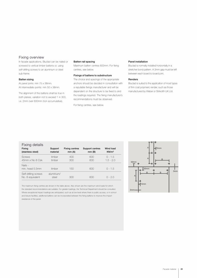
Facade material 81
Fixing overviewIn facade applications, Bluclad can be nailed or
screwed to vertical timber battens or, using
self-drilling screws to an aluminium or steel
sub-frame.
Batten sizing
At panel joints: min 75 x 38mm.
At intermediate points: min 50 x 38mm.
The alignment of the battens shall be true in
both planes, variation not to exceed 1 in 300,
i.e. 2mm over 600mm (non accumulative).
Batten rail spacing
Maximum batten centres 600mm. For fixing
centres, see below.
Fixings of battens to substructure
The choice and spacings of the appropriate
anchors should be decided in consultation with
a reputable fixings manufacturer and will be
dependent on the structure to be fixed to and
the loadings required. The fixing manufacturer’s
recommendations must be observed.
For fixing centres, see below.
Panel installation
Bluclad is normally installed horizontally in a
stretcher bond pattern. A 3mm gap must be left
between each board to board joint.
Renders
Bluclad is suited to the application of most types
of thin coat polymeric render, such as those
manufactured by Weber or Strikolith UK Ltd.
Fixing detailsFixing Support Fixing centres Support centres Wind load(stainless steel) material mm (A) mm (B) KN/m2
Screws timber 400 600 0 - 1.545mm x No 8 Csk timber 300 600 1.5 - 2.0
Nails - min. head 5.5mm timber 150 600 0 - 1.5
Self-drilling screws aluminium/No. 8 equivalent steel 300 600 0 - 2.0
The maximum fixing centres are shown in the table above. Also shown are the maximum wind loads for which
the standard recommendations are suitable. For greater loadings, the Technical Department should be consulted.
Where exceptional impact loadings are anticipated, such as at low level where there is public access, or in school
and leisure facilities, additional battens can be incorporated between the fixing battens to improve the impact
resistance of the panel.
B
BB
A
A
A
3mm
15mm
50mm
50mm
3mm
15mm

82 Facade material
Profiled sheeting
Clip fabricated from13 x 3.2mm steel barand galvanized
SFS fixing oncrest of corrugation2 no. per sheet
Support clip usedon trough ofcorrugation2 no. per sheet
Liner sheet
Ashgrid AG40 support system fixed in accordance with Ash & Lacy recommendations
Profiled sheeting can be used in a wide range
of vertical details for commercial, industrial,
residential and agricultural applications.
Top fix systems When fixing Profile 6 using top-fix fasteners on a vertical application,
some provision must be made to support the weight of the sheets,
otherwise the sheets will sag down from their intended position and
both the fasteners and the fibre cement will be overstressed.
The base of each sheet should be supported on two support clips
which hook over the sheeting rail. The support clips should be
positioned in the valley corrugations adjacent to the fixing position.
Valley fastenersAn alternative solution, which doesn’t require the support clips,
is to fix the sheets in the valley corrugations. The sheets should be
pre-drilled with a 2mm oversize hole.
Typical double skin vertical cladding
Profile 6, Rob
in Hoo
d Prim
ary Sch
ool, Nottingh
am
Profile 3, Ensworth Coa
stal Hou
se, Ham
pshire

Facade material 83
Window detail
Marley Eternitprofiled sheeting
Ashgrid bracketand support bar
Breather membrane
Window frame
Mastic
DPC
Horizontal zinc flashing
Window frame
Mastic
DPC
Marley Eternit jamb filler
Marley Eternit profiledsheeting
Ashgrid bracket and support bar
Breather membrane
Min 10mm air gap
Head detail
Profile 6, Erskine
Garde
n Cen
tre, S
cotland
Profile 6, Sanda
l Mag
na Sch
ool, Wakefield

Vertical tile hanging
84 Facade material
Code 4 lead flashingat head
Eaves/top tile
38mm x 25mm tilingbattens at 115mm gauge
Approved underlay
Eaves/top tile
Code 4 lead flashingdressed over timbertilting fillet
Code 4 lead apron flashingfixed beneath sill anddressed over eaves/top tileby 100mm min.
Tile to form soffit
Exposed edge of tilesto be pointed incement mortar
65mmminimum
Plain tile
Plain tiling and slates are an excellent, weatherproof and
attractive cladding to the vertical walls of any building.
Vertical tiling with plain tilesFeature and ornamental tiles may also be used with normal plain tiles
to create decorative patterns. Fibre cement slates can also be used
for vertical cladding.
Ashdo
wne
Aylesham M
ix (roo
f) and Ashurst (vertical tiling and fittings)
Ashdo
wne
Aylesham, Collegiate Sch
ool, Berkham
sted

Thrutone
Blue/Black, W
imland
s Farm
, West S
ussex
Facade material 85
Vertical slating with fibre cement slatesFibre cement slates can be fixed to vertical surfaces and provide
an attractive and weatherproof cladding on both timber frame
and masonry constructions. Birkda
le Blue/Black, Tally Ho Police Training
College
, Birm
ingh
am

interchangeabilityadjustablecavity depths
detailinginternal corners
junctions
86 Fixing systems

88-89 Introduction
90-93 Timber battens
94-99 Omega and Zed
100-103 Ventisol
104-107 Ventispan
108 Secret fix systems introduction
109-111 Site bonding structural adhesive
112-113 Mechanical secret fix for EQUITONE [natura], EQUITONE [textura] and EQUITONE [pictura]
114-115 Fixings and accessories
light weightFixing systems
engineered
concealed fixing
Fixing systems 87

88 Fixing systems
Introduction
Timber battens (pages 90-93)
Economical and durable, timber battens are widely used for all
applications from fascias and soffits to total cladding.
Omega and Zed (pages 94-99)
A simple metal component system easily installed in a similar fashion
to timber battens with the added benefit of non-combustibility and a
completely rot-proof construction.
The variety of rainscreen facade solutions
available from Marley Eternit is matched by
a comprehensive range of fixing systems.
The interchangeability of panel and system means that the design
permutations are wide and careful choice of product and system
will allow any specifications to be met.
Visible fixing systems
The aesthetic end result of the various fixing options (i.e. whether panels
are visibly fixed, edge retained or secret fixed) are discussed on page 27.
In addition to the fixing systems detailed on this page, there are a number
of special systems and applications for Marley Eternit Cladding Panels
such as tunnel lining, infill panels, balconies, portable buildings etc.
Ventisol (pages 100-103)
A highly engineered system of top quality components specially
developed for fixing to new or existing structures. The adjustment
within the components allows a true plane to be easily achieved
for the new cladding facade.
Ventispan (pages 104-107)
The Ventispan system provides a framework for the cladding of both
concrete and steel framed structures, and is designed to be anchored
to the structure at each floor level with vertical profiles spanning from
floor to floor between anchor/bracket positions.

Fixing systems 89
Application InstructionsMarley Eternit offer a full range of Application Instructions for their fixing
systems, setting out detailed design and installation data.
Please contact the Technical Advisory Service for further information on
01283 722588.
Site bonding structural adhesive (pages 109-111)
The structural bonding system utilises structural adhesives to fix internal
and external cladding panels for a secret fix system.
Mechanical secret fix (pages 112-113)
This secret fix system is suitable for use with 12mm thick fibre cement
material and supports the cladding panels by means of aluminium profiles.
Fixings and accessories (pages 114-115)
Marley Eternit offer a comprehensive range of fitting and accessories
purpose-designed to work with our cladding systems and to provide
maximum design and fixing flexibility for all of the above fixing systems.
The range includes:
• Corner pieces
• Colour matched screws and rivets
• Horizontal joint trims
• Perforated closures
• Flexible jointing strips
Secret fix systems
All of Marley Eternit facades can be
installed on to the BENCHMARK Konnect
or Karrier Panel System using a secret-fix
or face-fix solution. Two build options
from BENCHMARK that are simple and
fast to install.
For further details please contact:
Tel: +44 (0)1352 716100
Email: [email protected]
www.kingspanbenchmark.com

Timber battensintroduction
90 Fixing systems
Horizontal joint alternativesHorizontal joints may be formed using Marley
Eternit horizontal joint profiles Type HJP.
Alternatively, an open joint detail may be used.
Dimension (mm)
Product - EQUITONE a
[natura] 10
[pictura] 10
[textura] 10Horizontal open joint
a
An economical method
of application for Marley
Eternit facade panels is
that of mounting on a timber
framework using rainscreen
construction principles.
Unless specific fire performance requirements
or irregularities to the substrate are encountered
(where other adjustable Marley Eternit Systems
are employed), timber battens will provide an
economical and speedy installation.
Timber protectionTimber battens can be protected against decay
and insect attack in accordance with BS 5268:
Part 5.
a
Horizontal joint profile type HJP
170
mm

Fixing systems 91
Vertical joint and intermediatepanel fixingMarley Eternit supply black flexible jointing strips
to protect and close vertical joints.
EFPS 36mm – standard panel joints
EFPS 60mm – corner joints
Note: To ensure an even surface, an EFPS 36 strip should beplaced behind intermediate panel fixing.
Timber battensvertical joints & corner profiles
38mm38mm
6-10mmEFPS 36EFPS 36
100mm50mm
3mm
3mm
External corner
Universal corner profile – UCP
For good site practice it is necessary to vary
the position of screw fixings to ensure that
adequate penetration occurs. The example
below illustrates a batten configuration
employing 38mm deep battens and the
respective screw positions3mm
EFPS 60
3mm
EFPS 60
Open joint – externalOpen joint – internal
CornersCorners are created using flat sheets and the
appropriate jointing strips and corner profiles.
Universal corner profiles
These are supplied black or mill finished as
standard.

92 Fixing systems
Head
Cill
10mm air gap
Batten
Flashing
10mm air gap
3mm
min
100mm max
Perforatedclosure
Batten
Aluminiumflashing
JambFor all jambs in excess of 100mm, additional
fixings are required.
Base of cladding Top of cladding
Typical window detail
Brickwork abutment
Timber battenscladding junctions

Fixing systems 93
Timber battensfixing details
Batten sizingScrews
Panel joints min 100 x 38mm
Intermediate min 50 x 38mm
Larger battens are required if fixings are more
than 25mm from the vertical edge.
High wind loadings or exceptional impactrequirementsShould wind loading exceed ± 2.0 kN/m2,
please consult the Technical Advisory Service.
Where exceptional impact levels to cladding
panels can be anticipated, i.e. low level
applications near pedestrian access, schools,
leisure facilities etc., additional timber battens,
between the fixing batten, can be incorporated
to increase the panel's resistance.
Surface mounted featuresWhere other building features, i.e. signs,
gutters, canopies etc. are to be fixed then
additional batten work should be included
and clearance holes must be provided
through the cladding. Under no circumstances
should cladding panels receive any additional
structural loads.
A
B
DF E
C
Screw holesPre-drilled holes dimensions for the panels
are set out below:
Facades – EQUITONE Fixed hole
(if required)
[natura] 6mm
[natura] with Pro coating 7mm
[tectiva] 5mm (fixed point)
8mm (all other holes)
[pictura] 7mm
[textura] 6mm
Fixing centres (all dimensions in mm) – EQUITONEProduct [natura]* [tectiva] [pictura] [textura]
8mm 8mm 8mm
Windload
kN/m2 1.5 1.5 1.5 1.5
Dims
A 25 25 25 25
B 75-100 75-100 75-100 75-100
C 600 600 600 600
D 600 600 600 600
E 600 600 600 600
F 10 8-10 10 10
Fixing length 35 38 35 35
* For EQUITONE [natura] with Pro coating, call our Technical Advisory Service on 01283 722588.
N.B. In all cases it is important to have the
corner fixings staggered at unequal spacings
from the two edges.

94 Fixing systems
25-40m
m
Omega and Zedintroduction
Omega profileThe Omega profile is supplied in 6m lengths and employed
at panel joints. Weight = 1.1kg/lin. metre
Zed profileThe Zed profile, also supplied in 6m lengths, is used at intermediate,
corner and abutment positions. Weight: 0.9kg/lin. metre
25-40m
m
As an alternative to timber battens,
particularly where there is a specific
requirement for non-combustible
frameworks, a lightweight aluminium
framework can be used.
These can be fixed either directly to a concrete, brick or
block wall, or to a purpose-designed rail system. Marley
Eternit’s facade material, EQUITONE [natura], EQUITONE
[tectiva], EQUITONE [pictura] and EQUITONE [textura] can
then be rivet-fixed to the Omega and Zed.

Fixing systems 95
Fixing to horizontal jointsWhere it is envisaged that Omega and Zed are
fixed to a horizontal rail system please note:
• The rail centres should not exceed 1500mm
• A wind barrier should be sheathed over the
front of the horizontal rails
All profiles and fixing accessories are carefully
selected for their compatibility in normal
atmospheric conditions.
ProfilesMaterial
Aluminium to BS 1474 Grade 6082 T6.
Finish
Mill finish.
Omega and Zedhorizontal joints
Anchoring of Omega and Zedto building substrateThe profiles should be affixed adequately back
to a wall/rail system with suitable proprietary
anchors or fixings. The Omega and Zed profiles
have been designed to span up to 1500mm
where dynamic wind loadings do not exceed
± 2.0kN/m2.
The design and selection of a specialist anchor
to suit the substrate's characteristics should be
based on engineering calculations and referred
to reputable manufacturers such as Hilti,
Fischer, Leibig, Rawlplug, Buildex, Spit etc.
A 10mm expansion joint should be provided
between vertically adjacent Omega and Zed
profiles, with an anchor provided within 200mm
of the ends of all profiles.
High wind loadings orexceptional impactrequirementsShould wind loading exceed ± 2.0kN/m2,
please consult the Technical Advisory Service.
Where exceptional impact levels to cladding
panels can be anticipated, i.e. low level
applications near pedestrian access, schools,
and leisure facilities, additional rails can be
incorporated to increase the panel’s resistance.
8-10
mm
Horizontal open joint
8-10
mm
Horizontal joint profile type HJP
170m
m
Horizontal joint alternativesHorizontal joints may be formed using aluminium
joint profiles type HJP. Alternatively, an open
joint detail may be used.
With an open joint, the aluminium profiles will be
visible between two panels. Black paint or PVC
tape can be used to mask this effect.

96 Fixing systems
Omega and Zedvertical joints & corner profiles
Vertical joint and intermediate fixing
External corner
Universal corner profile (UCP)
UCP
Zed profile
3mm
3mm
250mmmax
Omega profile Zed profile
Internal corner
Universal
corner profile
Showing close-up
view of UCP corner
detail.
3mm joint
Zed profile
60 x 60mm angle
250m
m m
ax.

Fixing systems 97
Flashing
10mm air gap
Omega/Zed profile
Top of cladding Brickwork abutment
Zed profile 3mmmin
Perforatedclosure
Aluminium flashing
Omega/Zed profile
Base of cladding
250mm max
100mm max
Head
Cill
10mmair gap
Typical window detail
JambFor all jambs in excess of 100mm, additional
fixings are required.
Omega and Zedcladding junctions

98 Fixing systems
Rivet holesFacades are supplied by Marley Eternit fabricators with the fixing holes
pre-drilled to an agreed pattern.
Hole sizesPre-drilled holes in the panels shall be as described in the relevant
Application Instructions. For full fixing information, please refer to the
Technical Advisory Service.
40mm
70m
m
592mm 592mm 592mm 592mm 592mm 40mm
540m
m54
0 m
m70
mm
3040mm
1220
mm
F = fixed point
Typical panel/holing layoutExample using EQUITONE [natura].
Omega and Zedfixing details
D
E
B
C
A
Omega and Zed profile spacingProfiles are spaced horizontally across the elevation to suit the panel
requirements, up to maximum centres of 600mm.
Universal corner profiles (aluminium)These are supplied black or mill finished as standard.
Maximum panel rivet fixing centres (all dimensions in mm) for all productsWindload kN/m2 up to 1.5 1.5 – 2.0
Dims A 40 40
B 75-100 75-100
C 600 500
D 600 500
E 10 10

Fixing systems 99
EQUITONE [natura], Brune
l University, Uxbridge

100 Fixing systems
Ventisolintroduction
An aluminium frame fixing
system able to provide
adjustable void depths
to accommodate insulation,
and able to overcome
irregularities in the
supporting substrate.
Components
8-10
mm
Horizontal open joint
8-10
mm
Horizontal joint profile type HJP
170m
m
Horizontal joint alternativesHorizontal joints may be formed using aluminium
joint profiles type HJP. Alternatively, an open
joint detail may be used.
With an open joint, the aluminium profiles will be
visible between two panels. Black paint or PVC
tape can be used to mask this effect.
‘T’ profile
‘L’ profile
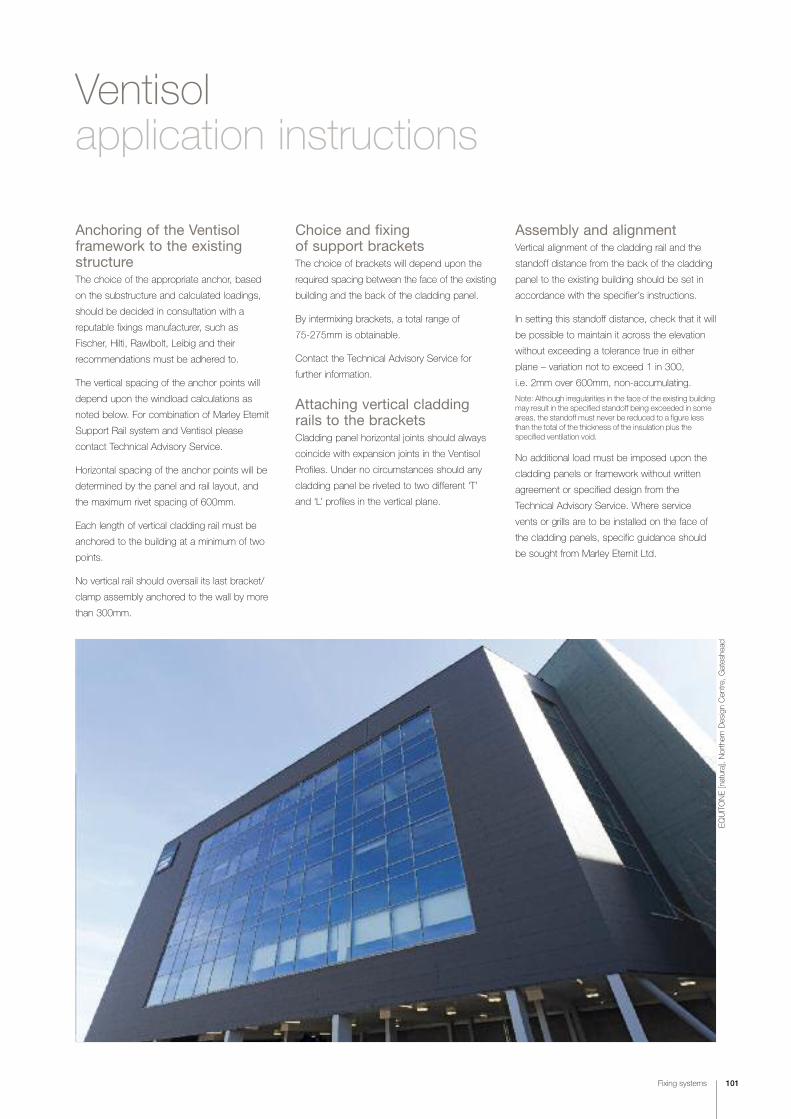
Fixing systems 101
Ventisolapplication instructions
Anchoring of the Ventisolframework to the existingstructureThe choice of the appropriate anchor, based
on the substructure and calculated loadings,
should be decided in consultation with a
reputable fixings manufacturer, such as
Fischer, Hilti, Rawlbolt, Leibig and their
recommendations must be adhered to.
The vertical spacing of the anchor points will
depend upon the windload calculations as
noted below. For combination of Marley Eternit
Support Rail system and Ventisol please
contact Technical Advisory Service.
Horizontal spacing of the anchor points will be
determined by the panel and rail layout, and
the maximum rivet spacing of 600mm.
Each length of vertical cladding rail must be
anchored to the building at a minimum of two
points.
No vertical rail should oversail its last bracket/
clamp assembly anchored to the wall by more
than 300mm.
Choice and fixing of support bracketsThe choice of brackets will depend upon the
required spacing between the face of the existing
building and the back of the cladding panel.
By intermixing brackets, a total range of
75-275mm is obtainable.
Contact the Technical Advisory Service for
further information.
Attaching vertical claddingrails to the bracketsCladding panel horizontal joints should always
coincide with expansion joints in the Ventisol
Profiles. Under no circumstances should any
cladding panel be riveted to two different ‘T’
and ‘L’ profiles in the vertical plane.
Assembly and alignmentVertical alignment of the cladding rail and the
standoff distance from the back of the cladding
panel to the existing building should be set in
accordance with the specifier’s instructions.
In setting this standoff distance, check that it will
be possible to maintain it across the elevation
without exceeding a tolerance true in either
plane – variation not to exceed 1 in 300,
i.e. 2mm over 600mm, non-accumulating.
Note: Although irregularities in the face of the existing buildingmay result in the specified standoff being exceeded in someareas, the standoff must never be reduced to a figure lessthan the total of the thickness of the insulation plus the specified ventilation void.
No additional load must be imposed upon the
cladding panels or framework without written
agreement or specified design from the
Technical Advisory Service. Where service
vents or grills are to be installed on the face of
the cladding panels, specific guidance should
be sought from Marley Eternit Ltd.
EQUITONE [natura], Northern Design Cen
tre, Gateshe
ad
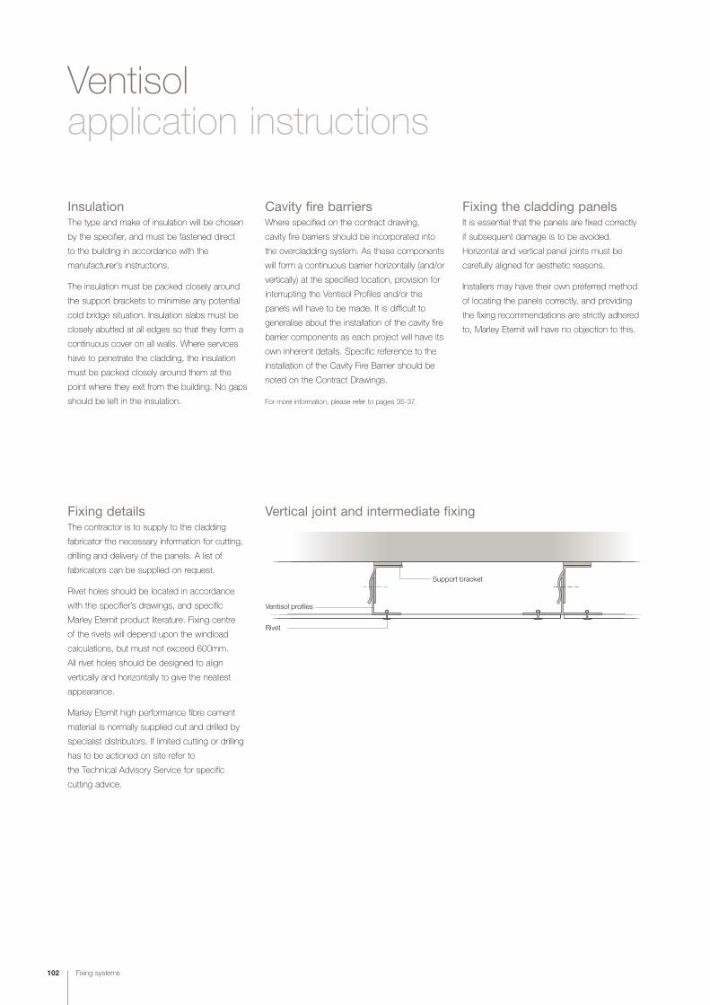
102 Fixing systems
Ventisolapplication instructions
InsulationThe type and make of insulation will be chosen
by the specifier, and must be fastened direct
to the building in accordance with the
manufacturer’s instructions.
The insulation must be packed closely around
the support brackets to minimise any potential
cold bridge situation. Insulation slabs must be
closely abutted at all edges so that they form a
continuous cover on all walls. Where services
have to penetrate the cladding, the insulation
must be packed closely around them at the
point where they exit from the building. No gaps
should be left in the insulation.
Fixing detailsThe contractor is to supply to the cladding
fabricator the necessary information for cutting,
drilling and delivery of the panels. A list of
fabricators can be supplied on request.
Rivet holes should be located in accordance
with the specifier’s drawings, and specific
Marley Eternit product literature. Fixing centre
of the rivets will depend upon the windload
calculations, but must not exceed 600mm.
All rivet holes should be designed to align
vertically and horizontally to give the neatest
appearance.
Marley Eternit high performance fibre cement
material is normally supplied cut and drilled by
specialist distributors. If limited cutting or drilling
has to be actioned on site refer to
the Technical Advisory Service for specific
cutting advice.
Fixing the cladding panelsIt is essential that the panels are fixed correctly
if subsequent damage is to be avoided.
Horizontal and vertical panel joints must be
carefully aligned for aesthetic reasons.
Installers may have their own preferred method
of locating the panels correctly, and providing
the fixing recommendations are strictly adhered
to, Marley Eternit will have no objection to this.
Cavity fire barriersWhere specified on the contract drawing,
cavity fire barriers should be incorporated into
the overcladding system. As these components
will form a continuous barrier horizontally (and/or
vertically) at the specified location, provision for
interrupting the Ventisol Profiles and/or the
panels will have to be made. It is difficult to
generalise about the installation of the cavity fire
barrier components as each project will have its
own inherent details. Specific reference to the
installation of the Cavity Fire Barrier should be
noted on the Contract Drawings.
For more information, please refer to pages 35-37.
Ventisol profiles
Support bracket
Rivet
Vertical joint and intermediate fixing

Fixing systems 103
Support bracket
Ventisol profile
Rivet
Universal corner profile
Support bracket
Ventisol profile
Rivet
250mm max
Ventisol profiles
Support bracket
Perforatedclosure
250mm
Pre-formed cill
Ventisol profiles60 x 60mm angle
Rivet
Support bracket
250mmmax
Corners
Internal corner
Brickwork abutment
Rivet
3mm min
Ventisol profile
Support bracket
Window jamb Perforated closure piece
Expansion joint
200mm max 40mm
Rivet 'L' Profile 'T' Profile
No fixing required
100mm 100mm
External corner

104 Fixing systems
Ventispanintroduction
A highly adjustable system
allowing for irregularities in
substrate surface, Ventispan
is ideal where poor quality
infill material on existing
buildings dictates that
fixings can only be secured
at floor slab positions.
Components
10mm
8-10
mm
Horizontal open joint
8-10
mm
Horizontal joint profile type HJP
170m
m
Horizontal joint alternativesHorizontal joints may be formed using aluminium
joint profiles type HJP. Alternatively, an open
joint detail may be used.
With an open joint, the aluminium profiles will be
visible between two panels. Black paint or PVC
tape can be used to mask this effect.

250mm max
Fixing systems 105
Ventispanapplication instructions
Anchoring Ventispan to theexisting structureThe system is designed to be anchored into
floor slabs. The choice of appropriate anchor
based on the substructure and calculated
loadings should be decided in consultation
with a reputable fixings manufacturer.
Pull out tests of primary anchors must be
compared with the system’s design requirements,
with an adequate factor of safety. Formal
certification of any testing should be kept.
The vertical spacing of the brackets anchor
points will depend upon wind load calculations,
which should be undertaken by a competent
engineer. The vertical spacing must not
exceed 3 metres without the written approval
of Marley Eternit.
The horizontal spacing of bracket anchor
points across the facade will depend on wind
loadings, choice of panel material and panel
layout but will not normally exceed 625mm.
Spacings in excess of this can be permitted
but only with the use of stiffened panels and
the prior approval of Marley Eternit.
Choice and fixing of support bracketsThe choice of bracket type will initially depend
upon the required cavity spacing of the
installation.
Brackets allow a cavity range from 95-225mm
Anchoring
All brackets should be secured to the structure
with one anchor in the central slot (which allows
for some sideways adjustment). Where a single
anchorage cannot be made, alternative brackets
provide for dual anchors in side wings.
The brackets must be installed at 90° ± 2 to
the structure with plumb alignment.
If the existing structure’s surface is irregular,
local concrete repairs should provide a flat base
for the bracket.
Isolation membranes are required where brackets
are in contact with new concrete pads, repairs.
At external corners the bracket/rail position must
accommodate the maximum over sail of the
panels 250mm.
Due consideration should be given to the
positioning of primary anchors to achieve
minimum edge dimensions.
Anchor bolts should not protrude so as to foul
fitting of the rails.
Attaching rails to the bracketsVentispan rails can be installed either from the
top of the structure working down or from the
bottom of the structure working up. Experience
has shown the latter to be more common
practice.
The brackets are designed to grip the rails via
the ‘helping hand’ principle. Thus the rails can
be easily aligned by tapping in or out of the
‘helping hand’ prior to fixing.
The rails are connected together with a splice
sleeve which can also be secured with the
bracket rail fixing.
There must be a 10mm gap at rail connections
and this splice sleeve must only be fixed one
side of the connection to allow for expansion.
Note: For safety reasons it is preferred, unless otherwiserequired, to pre-rivet the splice sleeve into the bottom of each rail before positioning.
625mmmax.
Floorslab
Floorslab
3000mmmax.

106 Fixing systems
Ventispan bracket
Rivet
Ventispan rail
Aluminium angle
Ventispan bracket
Rivet
Ventispan rail
Aluminium angle
Internal corner
Ventispanapplication instructions
Bracket to rail fixingsSliding Bracket Fixing
Inevitably one Ventispan rail, usually at the top,
will have to be fixed to two brackets. To allow
for possible thermal expansion a special slotted
bracket should be used.
Oversail
Maximum rail oversail from support brackets
600mm. The rails must fit into the brackets a
minimum of 40mm leaving a maximum 70mm
visible depth of rail.
Nylon washerSteel washer
Nylon washerSteel washer
M8 nut
Locknut600mmmax
95-225mm
Ventispan bracket
Ventispan rail
Rivet
UPC
250mmmax
External corner UCP
Rivet
Ventispan rail
Ventispan bracket
max 8-10mm
Vertical joint and intermediate fixing

RivetUniversal corner profile
Ventispan rail
Ventispan bracket
Fixing systems 107
InsulationThe type and make of insulation will be chosen
by the specifier, and must be fastened direct
to the building in accordance with the
manufacturers’ instructions. Insulation should
be vapour permeable to allow water vapour to
migrate from the structure into the cavity.
The insulation must be packed closely around
the support brackets to minimise any potential
cold bridge situation.
Insulation slabs must be closely abutted at all
edges so that they form a continuous cover on
all walls. Where services have to pass through
the cladding zone, the insulation must be
packed closely around them at the point where
they exit from the building. No gaps should be
left in the insulation.
Cavity fire barriersCavity fire stops may be required to be installed
on any multi-storey structure. Placement of
these will be as required by the specification
and/or as detailed on the drawings.
At the required fire stop location the support
angle is fixed to the structure at 500mm centres
along the angle up stand. The slotted fire stop
is then positioned with the leading edge flush
with the face of the rails and rivet fixed to the
support angle at 300mm centres.
Where Ventispan rails pass through the fire
barrier, it should be neatly trimmed and
intumescent foam used to close all gaps.
Ventispan bracket
Ventispan rail
Rivet
Aluminium flashing
10mm air gap
Perforated closure
Aluminium flashing
10mm air gap
Rivet
Ventispan rail
Ventispan bracket
Top of cladding Base of cladding
JambCill
10mm air gap
Horizontal carrier rail
Spandrel railend cleat
Vertical carrier railwith black-out tapeor buffer tape (high rise)
Window and cill detailto project requirements
‡MoreSee pages 35-37 for more information about
fire safety.

108 Fixing systems
Secret fix systemsintroduction
The fixing method chosen can have a fundamental and
dramatic effect upon the final appearance of the facade.
Employing a secret fix method will result in a sheer, smooth
facade unobstructed by fixings.
In practice, many versions of secret fixing exist, including
infill or composite panels.
This design guide however provides details for two specially
developed Factory fabricated systems, and also a structural
bonding system developed for on site use.
Site bonding is limited to application within the temperature
range 5°C to 35°C and only in dry weather (check with
adhesive manufacturer).
Structural bonding Mechanical secret fix (for EQUITONE [natura], EQUITONE [textura]
and EQUITONE [pictura])

Fixing systems 109
Site bonding structural adhesiveintroduction
Panels bonded on timber substratePanels bonded on Marley Eternit aluminium
framework
The structural bonding
system utilises structural
adhesive to fix both internal
and external cladding
panels to a support
framework. It will bond
panels to either a timber
or aluminium framework.
The system employs a combination of double
sided tape and continuous beads of adhesive
to fix the panels.
The double sided tape controls the spread of
adhesive as the panel is applied and provides
initial contact retention whilst the adhesive
cures.
Extensive testing by participating companies
has demonstrated the performance of the
structural adhesive in several important areas.
• Laboratory testing indicates that the
structural adhesive will have an expected
life in excess of 40 years
• The adhesive remains permanently
flexible during the life of the product,
accommodating hydro-thermal movements
in the structure and the cladding panel
• Factors of safety, both short and long term,
indicate that both static and dynamic loads
can be more than adequately resisted.
In fact, the safety factors are many times
greater than traditional methods of fixing.
Fixing centres – EQUITONEFramework
centres (mm)
for max 2kNm2 windload
[natura] 500
[tectiva]* 500
[pictura] 8mm 500
[textura] 500
* Restrictions apply, please contact the Technical Advisory
Service for further information on 01283 722588.

110 Fixing systems
Site bonding structural adhesivedesign details
Ventisol profiles
Support bracket
Double sided tape Adhesive
8-10mm
Horizontal joint alternativesHorizontal joints may be formed using aluminium
joint profiles type HJP 70. Alternatively, an open
joint detail may be used.
With an open joint, the aluminium profiles
or timber will be visible between the panels.
Black paint or PVC tape can be used to
mask this effect.
Horizontal open joint Horizontal joint profile type HJP70
Vertical panel joint and intermediate fixing70
mm
8-10mm

Fixing systems 111
Ventisol profiles60 x 60mm angle
Double sided tape
Adhesive
250m
m m
ax
Support bracket
Universal corner profile
Support bracket
Ventisol profile
250mm max
Perforatedclosure
Aluminiumflashing
Ventisol profiles
Support bracket
Flashing
Support bracket
Ventisol profiles
10mm air gap
10mm air gap
CornersExternal corner
Typical details showing panelsfixed to the Ventisol system
3mm
3mm
Internal corner
Universal
corner profile
Showing close-up
view of UCP corner
detail.

112 Fixing systems
Undercutanchor
Bolt
Washer
Adjustablescrews at topof panel only
Panel hanger
Horizontal rail
Mechanical secret fix
Undercut anchorsMarley Eternit supply specially designed plugs
for fixing into pre-drilled holes in the backs of the
panels. These ensure a positive fixing for bolts
into the panels. The special plugs also have
square collars to provide more secure location
in the square or rectangular holes in the hangers.
In facade applications wherea smooth unbroken surface is required, Marley Eternitoffer a concealed mechanical fixing system. Hangers arefixed to the rear face of12mm thick EQUITONE[natura], EQUITONE [pictura]and EQUITONE [textura]panels. The hangers hookonto horizontal rails, which, inturn, are fixed to vertical rails.
Fixing centresWind load kN/m2 Max anchor/rail spacing
0.5 750mm
1.0 620mm
1.5 500mm
2.0 420mm
ClipPre-drilled hole Plug locked in placePlug inserted

Fixing systems 113
Profile aluminiumundercut anchors
Ventisol profiles
Vertical carrier rail
3mm
Profile aluminiumundercut anchors
Ventisol profiles
3mm
Profile aluminiumundercut anchorswith levelling bolt
Pre-formed cill
Ventisol profiles
10mm air gap
Profile aluminiumundercut anchors
Pre-formed cill
Ventisol profiles
Perforated closerfixed to cleats 30x40mm
External cornerInternal corner
Top of cladding Base of cladding

114 Fixings and accessories
Fixings and accessories
a b 1mm
c a c
b
1mm
Screws (colour matched)
a
EFPS 36
36mm
Screw dimensions – EQUITONE
Dimensions (mm) a b c gasket sleeve
[natura] 35 15 5.5 No No
[tectiva] 38 12 4.8 No No
[pictura] 35 15 5.5 No Yes
[textura] 35 15 5.5 No No
Rivets (colour matched)
Rivet dimensions – EQUITONE
Dimensions (mm) a b c gasket spacer rivet-setting
tool
[natura] 40 18 15 No Yes No
[tectiva] 4.8 20 16 No Yes No
[pictura] 4.0 18 15 No Yes Yes
[textura] 4.0 18 15 No Yes No
Universal corner profiles (black and mill finish)
Universal corner profile dimensions – EQUITONE
Dimensions (mm) a
[natura] 8
[tectiva] 8
[pictura] 8
[textura] 8
Available in 2.5m lengths.
EFPS Profiles (black)
Marley Eternit supply two flexible jointing strips to protect
and close vertical joints when using timber battens.
EFPS 36 - standard panel joints
EFPS 60 - corner joints
Available in 100m rolls.
60mm
EFPS 60
Fixings and accessories 115
Horizontal joint profiles
170m
m
70mm*
Horizontal joint alternatives (black)Horizontal joints may be formed using aluminium joint profiles
type HJP. Alternatively, an open joint detail may be used.
With an open joint, the aluminium profiles will be visible between
two panels. Black paint or PVC tape can be used to mask this effect.
Available in 2.5m lengths*
* HJP 70mm only used with structural adhesive.
Perforated closuresPerforated closures are installed at the base of rainscreen cladding
constructions and can be selected to accommodate varying thicknesses
of insulation.
The perforations maintain airflow, whilst minimising ingress of birds,
insects and vermin.
Perforated closure dimensions
Dimensions (mm) a b
30 40
30 50
30 70
30 100
Available in 2.5m lengths.
b
a
rivetovercladding
COSHHBS 8200
maintenance
116 Health, safety and sitework

fixing CDMwork at height
118-119 Health, safety & sitework guidance
Health, safety and sitework 117
Health, safety& sitework

118 Health, safety and sitework
Health, safety & sitework guidance
Good cladding practice is the result of many years of
experience in the practical application of cladding across
a wide range of applications.
Marley Eternit offer a full range of Application Instructions
covering our facade material and fixing system ranges.
The following is an overview of some of the key factors
that should be considered prior to commencement of
actual fixing.
Safety regulationsThe Construction Regulations made under the
Factories Act 1961 comprise :
• The Health and Safety at Work Act 1974
• The Construction (Design and Management)
Regulations 2007
• The Management of Health and Safety at
Work Regulations 1999
• Control of Substances Hazardous to Health
Regulations 2002
• Work at Height Regulations 2005
• Health and Safety in Roofwork HSG33: 1999
Health and Safety CommissionControl of lead at work – Control of Lead at
Work Regulations 1998
Management of Health and Safety at Work
Regulations 1992 – Workplace (Health, Safety
and Welfare) Regulations 1992 – Approved
code of practice, regulations and guidance.
Cutting to sizeAll facade material
These products have a hard decorative
coating fused to a dense fibre cement sheet.
To achieve the best results in respect of edge
finish and accuracy, the following points should
be carefully considered and employed.
Alternatively, contact a Marley Eternit fabricator.
• Firm work benches capable of fully
supporting the panel
• Clamp two sheets face to face
• Saw blades of the highest quality should be
used; Diamond or tungsten carbide cutting
blades for angle grinders; Diamond dusted
circular saws: Diamond dusted or tungsten
carbide black jigsaw blades
• Speed of cut will be dependent on the
power tool used and by practical trial.
General
When cutting any high performance facade
material care must be taken to avoid direct
contact of the face with the cutting table.
Ideally only one sheet should be cut at a
time and protected clamps should be used
to hold the panel rigid on the work bench to
avoid any slipping.
COSHH StatementsFor a copy of the Marley Eternit COSHH
datasheets, visit www.marleyeternit.co.uk
FabricatorsAll Marley Eternit high performance facade
material is supplied through a network of
fabricators who specialise in cutting to size,
pre-drilling and supplying to site complete with
all approved accessories. They will offer
assistance with site measurement, applications,
fixing advice etc.
Marley Eternit always recommend the
pre-cutting and drilling of their products by
fabricators and that quality standards, especially
of edge detail where visible be established
with the fabricator prior to commencement of
supply of material.
In situations where pre-cutting/drilling cannot
be carried out because of the irregular site
conditions, then limited on-site working can
be carried out as follows.

Health, safety and sitework 119
‡Moreliterature COSHH data sheets
Tel 01283 722588
Web www.marleyeternit.co.uk
advice E-mail [email protected]
Tel 01283 722588
DrillingFibre cement
High speed masonry drills are recommended
for drilling these products. Where possible two
flat sheets of material should be clamped face
to face.
Forming notches and apertures
When it is necessary to form notches or
apertures in panels for vent pipes etc., then
consideration must be given to the relative size
of opening compared to the panel dimension
as excessive sizing may weaken the panel to
the detriment of site handling and installation.
To achieve the best results, the corner
positions for notches and apertures should first
be drilled out and then saw the panels up to
these points. Immediately after cutting / drilling,
remove dust using a vacuum or soft brush or
dry soft and clean cloths. Cut edges of
EQUITONE [natura], EQUITONE [pictura],
EQUITONE [textura] and Cedral Weatherboard
woodstain must be sealed with Luko solution.
It is also advisable to coat the undercoat anchor
holes with Luko solution.
Handling
Always lift panels off each other, never slide
since scratching may occur. To carry panels
stand on edge and lift with two people (one
person at each end) protecting the face from
scratching or damage.
Applications instructions
Further information is available from Marley
Eternit on request.
General site workIt is important to note that any unevenness of
the framework to which the cladding panels are
affixed may be reflected in the finished surface.
Special attention must be paid to the accuracy
of frame spacing, alignment, level, joint widths,
panel layout and fixing arrangements.
Storage
Panels are supplied with protective paper or
plastic between the decorated faces. This
protection should not be removed, nor should
panels be placed face to back before fixing.
All Marley Eternit high performance materials
must be stored flat on pallets, inside and
undercover in dry conditions, protected from
weather and other trades. If moisture is allowed
to penetrate between the stored sheets,
permanent surface staining may occur.
Stacked on a level surface
maximum400mm
Store under cover Must be protected from the weather
Do not drag sheets off the stack Sheets must be lifted off the stack Carry on edge but do not store on edge

ecopoints
reducing
ISO 14001
savingenergy
BREEAM
naturalresources
120 Sustainability and the environment

122-123 Adopting best practice
124 Assessing the sustainability of claddings
125 Measuring environmental success
Sustainability &the environment
wastecutting pollution
EcoHomes
Green Guide
Sustainability and the environment 121

122 Sustainability and the environment
Adopting best practice
EQUITONE [textura]l, Ken
dal C
ollege
, Lake District

Sustainability and the environment 123
”The issues of global warming,
climate change and their effect
on our environment are
becoming increasingly more
important throughout the
construction industry.
At Marley Eternit we are
at the forefront of helping our
customers and suppliers to
put environmental best practice
at the top of their agenda.
Sustainability policy
Marley Eternit are firmly committed to meeting
our customer requirements with regard to the
quality of our products and services, whilst
recognising the impact that our business
activities have on the environment.
We manage all of our activities to minimise
environmental impact by adopting good,
sustainable practice at every level of business.
We recognise the benefits of continual
improvement in product/service quality and
environmental performance, taking into account
technological and financial constraints.
Product development
Marley Eternit are well known for the
development and bringing to market of
environmentally sustainable products. Amongst
these are Solesia – a photovoltaic roof tile able
to generate electricity from sunlight – and
Ecologic, which has a unique ‘pollution-eating’
coating and which is manufactured from around
50% recycled materials.
Adopting best practiceThe driving force behind our environmental
practice is the optimisation of the sustainable
use of natural resources. The following
represent how Marley Eternit are leading the
way to turn sustainability into an everyday part
of our working life.
Reducing waste
Wherever possible, all our sites recycle waste
rather than send it to landfill. We’ve installed
waste-to-heat power plants at two of our
factories, converting all sorts of waste –
from cement bags to irreparably damaged
timber pallets – to heat. At the end of their life,
Marley Eternit products can be recycled, for
example as an aggregate in other concrete
products.
Saving energy
Electricity, gas, oil and water consumption is
measured and compared across our factories.
The monthly data helps us to identify where
improvements can be made. At one site we
periodically use methane produced by a local
landfill to generate the heat which cures tiles
and heats the workplace.
Cutting pollution
Marley Eternit products provide no direct risk of
pollution to either the air or water. The stable
and inert waste products derived from them can
either be recycled or – where that’s not possible
– used as bulk material for landscaping etc.
On the roads, we use eco-friendly, low-
emission and fuel-efficient vehicles and where
possible ensure that there is a return load for
every trip.
“Sustainability is that which meets the needs of
the present without compromising the ability of
future generations to meet their own needs...The United Nations World Commission on the Environment and Development

124 Sustainability and the environment
BRE Green Guide 2008 on-lineThe BRE ‘Green Guide’ online:
www.thegreenguide.org.uk
contains a listing of building materials and
components which are assessed in terms of
their environmental impact across their entire
life cycle – from ‘cradle to grave', within
comparable specifications.
The Green Guide contains more than 1200
specifications used in various types of building
which examine the relative environmental
impacts of the construction materials commonly
used in six different generic types of building
covering six sectors.
Materials and components are arranged on an
‘building element’ basis so that designers and
specifiers can compare and select comparable
systems or materials that may be used in, say,
roofs, walls, floors etc.
Across these building element categories, the
Guide provides an extensive, but not complete
catalogue of building specifications covering
most common building materials.
Assessing the sustainability of claddings
At Marley Eternit, we wereamong the first in the industryto achieve ISO 14001accreditation, the internationallyrecognised environmentalmanagement standard.
All of our products are able toachieve an A or A+ rating whenused in those constructionsspecified in the new BRE‘Green Guide to Specification’.
This data is set out as an A+ to E ranking
system, where A+ represents the best
environmental performance/least environmental
impact, and E the worst environmental
performance/most environmental impact.
BRE has provided a summary environmental
rating – ‘The Green Guide’ rating – which is
a measure of overall environmental impacts
covering the construction specifications
(i.e. they are not manufacturer specific).
Ratings tablesFor each element, the ‘Green Guide’ ratings are
displayed alphabetically in tables. Depending on
the number of specifications, the element group
may have been divided into sub-categories.
The ratings are based on the range for the
whole element group, not the sub-categories.
The table below contains information taken
from ‘The Green Guide’ and details some
of the specifications covered in the rainscreen
cladding section.
RatingsWhen used in one of the construction types† listed in the
table right, fibre cement claddings achieve an A+ rating.
† The constructions shown right are excerpts from the ‘Green Guide to Specification’. There are many other constructions covered at www.the-greenguide.org.uk
A+
A
C
D
B
Commercial external wall construction
Rainscreen cladding Summary rating
Steel frame with block infill
Autoclaved fibre cement single sheet and timber battens, breather A+membrane, insulation, structural steel frame, medium dense solid blockwork with cement mortar, plasterboard on battens, paint (element no. 806230421)*
Coated aluminium profiled single sheet and steel support, breather membrane, Ainsulation, structural steel frame, medium dense solid blockwork with cement mortar, plasterboard on battens, paint (element no. 806230419)*
Precast concrete panel (non-load bearing) with "reconstructed stone" finish and Csupport system, structural steel frame, breather membrane, insulation, medium dense solid blockwork with cement mortar, plasterboard on battens, paint(element no. 806230429)*
Precast concrete panel with brick finish and support system, structural steel Cframe, breather membrane, insulation, medium dense solid blockwork with cement mortar, plasterboard on battens, paint (element no. 806230680)*
Precast concrete panel (non-load bearing) with limestone facing panels, Dsupport system, breather membrane, insulation, structural steel frame, medium dense solid blockwork with cement mortar, plasterboard on battens, paint (element no. 806230427)*
*Typical breakdown using element no. 806230421 (by environmental issues):
Summary Rating A+ Acidification AClimate change A Water extraction A+Mineral resource extraction A+ Stratospheric ozone depletion AHuman toxicity A+ Ecotoxicity to freshwater A+Nuclear waster (higher level) A+ Ecotoxicity to land AEutrophication A+ Photochemical ozone creation AWaste disposal A+ Fossil fuel depletion A
(Best)
E (Worst)
EQUITONE [natura], Com
mercial Europ
ean ap
plication

Sustainability and the environment 125
EQUITONE [natura], the Osb
orne
Hou
se at B
RE
‡MoreTo find more on the sustainability of
Marley Eternit systems, please visit the
following link:
marleyeternit.co.uk/environment
Code for Sustainable Homes The Code is designed to ensure homes are
built to progressively improving sustainability
ratings and that, by 2016, all newly built homes
achieve the highest (level 6), zero carbon rating.
Marley Eternit facade materials, in conjunction
with insulation and other products can help
materially improve the sustainability and
code ratings of new-build housing.
Measuring environmental success
BREEAM and the Green GuideThe BRE’s Environmental Assessment Method
(BREEAM) is a design and management stage
assessment tool that provides an environmental
label for buildings, based on good practice.
BREEAM is widely used to specify overall
environmental performance. One of the aims of
BREEAM is to encourage the use of materials
that have lower impact on the environment,
taking account of the full life cycle of the
materials in question.
How do materials credits within BREEAM and EcoHomes work?
BREEAM
Within BREEAM, materials credits are achieved
by specifying materials which achieve an ‘A’
rating in the Green Guide to Specification,
where at least:
Credits are available where significant use
of crushed aggregate, crushed masonry or
alternative aggregates are specified for high
grade aggregate uses (such as the building
structure, ground slabs, roads etc). Credits
are also available where materials used in
structural elements are responsibly sourced
(eg. materials should have EMS certification
such as ISO 14001).
EcoHomes
Within EcoHomes, materials credits are
achieved by specifying materials which achieve
an ‘A’ rating in the Green Guide to Specification.
Credits are also available where materials used
in key building elements (including the roof
structure and cladding) are responsibly sourced
(eg. from a manufacturer who has ISO 14001).
ManagementOverall management policy,commissioning site managementand procedural issues.
How does BREEAM work?BREEAM assesses the performance of
buildings in the areas shown:
Credits are awarded in each area according
to performance. A set of environmental
weightings then enables the credits to be added
together to produce a single overall score.
The building is then rated on a scale of Pass,
Good, Very Good or Excellent.
Specifiers are encouraged to consider these
issues at the earliest opportunity to maximise
their chances of achieving a high BREEAM rating.
EcologyEcological value conservation and enhancement of the site.
PollutionAir and water pollution issues.
Health and well beingIndoor and external issuesaffecting health and well being.
MaterialsEnvironmental implication ofbuilding materials, including life-cycle impacts.
Land useGreenfield and brownfield sites.
TransportTransport-related CO2 and locationrelated factors.
Energy useOperational energy and carbon dioxide (CO2) issues.
WaterConsumption and water efficiency.

fixingknowledgeon-line
specification creationQuantity estimation
fast information delivery
126 Services and support

128 Services & support
129 References
131 Index
Services
specificationsfast informationdelivery
samples
www.marleyeternit.co.uk
Services and support 127

128 Services and support
WebsiteOur site contains wide-ranging
information on all of our Facade ranges,
including colours and fixing systems
along with brochure and case
study downloads.
www.marleyeternit.co.uk/facades
Services & support
Technical Advisory ServiceWe are able to provide prompt,
knowledgeable and detailed responses
to a vast range of enquiries covering
everything from the embodied energy of
facade material, to the different fixing
options available.
Our Technical Advisory Service is staffed
by a qualified team with specialist
knowledge not only of all Marley Eternit
products, but also crucially, how those
systems integrate with other components
and comply with Building Regulations,
Health and Safety, environmental and
other critical criteria.
contact tel 01283 722588
e-mail [email protected]
Customer SupportMarley Eternit is committed to providing
outstanding customer care and is staffed by
experienced personnel. Services include:
Literature: All current product and technical
literature can be downloaded from:
www.marleyeternit.co.uk/downloads
contact tel 01283 722588
e-mail [email protected]
Samples: Facade samples are available
on request.
contact tel 01283 722588
e-mail [email protected]
web marleyeternit.co.uk/facades
Stockist information:
e-mail [email protected]
web marleyeternit.co.uk/findastockist
Advice and ordering information
contact tel 01283 722894
e-mail [email protected]
Training centreWe have a purpose-built training
centre where we are able to
impart our expertise and
demonstrate our ongoing
commitment to training within
our industry.
contact tel 01283 722588
e-mail [email protected]
BIMThe content of BIM models is ‘intelligent’
with detailed information such as
dimensions, component placement, material
specifications, carbon content, structural
performance, manufacturers’ details, and
maintenance requirements embedded.
BIM can produce 3D models of a building
using the specifications of all processes,
models and materials that will go into a
project, including plans, sections and
elevations.
Collaborative tool used by suppliers,
architects, specifiers, contractors alike
Greater predictability: ‘Build before
you build’
Faster project delivery
Less waste
Accurate analysis of performance
Generate ‘as-built’ drawings
After-build access for owners
and contractors
BIM services
contact tel 01283 722588
e-mail [email protected]
www.marleyeternit.co.uk/Resources/BIM
References 129
References
Relevant documents• BS 1202-1, Specification for nails – Part 1:
Steel nails.
• BS 5250, Code of practice for control of
condensation in buildings.
• BS 5268-2, Structural use of timber – Part 2:
Code of practice for permissible stress design,
materials and workmanship.
• BS 5268-5, Structural use of timber – Part 5:
Code of practice for the preservative treatment
of structural timber.
• BS 5925, Code of practice for ventilation
principles and designing for natural ventilation.
• BS 6399 -1,-2,-3, Loading for buildings.
• BS 6651, Code of practice for protection of
structures against lightning.
• BS 8000-6, Workmanship on building sites –
Code of practice for slating and tiling of roofs
and claddings.
• BS 8104:1992, Code of practice for assessing
exposure of walls to wind-driven rain.
• BS EN 300, Oriented strand boards (OSB) –
Definitions, classification and specifications.
• BS EN 312-5, Particleboards – Specifications
– Part 5: Requirements for load-bearing boards
for use in humid conditions.
• BS EN 312-7, Particleboards – Specifications –
Part 7: Requirements for heavy-duty load-
bearing boards for use in humid conditions.
• BS EN 313 (all parts), Plywood – Classification
and terminology.
• BS EN 622-3, Fibreboards – Specifications –
Part 3: Requirements for medium boards.
• BS EN 634-2, Cement-bonded particle boards
– Specification – Part 2: Requirements for OPC
bonded particleboards for use in dry, humid and
exterior conditions.
• BS EN 635 (all parts), Plywood – Classification
by surface appearance.
• BS EN 12811-1, Temporary works equipment.
Scaffolds. Performance requirements and
general design.
• BS EN 13501-2, Fire classification of
construction products and building elements,
Part 2- Classification using data from fire
resistance tests (excluding products for use
in ventilation systems).
• BS EN 14437, Determination of the uplift
resistance of installed cladding.
• EN 1187, Test methods for external fire
exposure to walls.
• BS EN 12467: 2004 Fibre cement flat sheets
– Product Specification and test methods.
• BS EN 438:6:2005, Decorative high pressure
laminates based on thermosetting review.
Classification and Specification for exterior
grade compact laminate of thickness 2mm
and greater.
• BS5588: Fire precaution in the design,
construction and use of buildings.
• BS EN 13501-1:2002, Fire classification of
construction products and building elements,
Classification using test data from reaction to
fire tests.
• BS 6093:2006, Code of practice for the design
of joints and jointing in building construction.
• BS 5427-1:1996: Code of practice for use of
profiled sheet for roof and wall cladding on
buildings.
• BS 476-6:1989: Fire tests, on building materials
and structures Method of Test for fire
propagation for products.
• BS 476-7:1997, Fire tests on building materials
and structures. Method of test to determine the
classification of the surface spread of flame of
products.
• CWCT, Standard for systemised building
envelopes.
• NHBC, Standards 2006:Chapter 6.9 curtain
walling and cladding.
Other publicationsConstruction (Design and Management)
Regulations 2007. London: The Stationery Office.
Construction Products (Amendment) Regulations
1994. London: The Stationery Office.
Control of Substances Hazardous to Health
Regulations 2002. London: The Stationery Office.
Building Regulations 2000, as amended by the
Building (Amendment) Regulations 2001, the
Building (Amendment) Regulations 2002 and the
Building (Amendment) (No 2) Regulations 2002.
London: The Stationery Office.
Thermal insulation: avoiding risks. BR 262.
London: CRC Ltd, 2002.
The Building (Scotland) Regulations 2004.
The Scottish Building Standards Agency.
Building Regulations (Northern Ireland) 2000.
London: The Stationery Office.
Limiting thermal bridging and air leakage robust
construction details for dwellings and similar
buildings. London: The Stationery Office, 2001.
Rainscreen cladding: A guide to Design Principles
and practice.
Anderson J.M & Gill JR (1998)
The Green Guide to Housing Specification
BRE, Jayne Anderson and Nigel Howard

130 Facades
Index 131
AAcoustics 34Aesthetics and colour 26-27Air leakage 39Aircraft vortices 33Airtightness 39Applications and sectors 8-19Astro, rivet fixing 55
BBase of cladding 88-115Batten sizing 88-115BBA, Certificates
Cedral Weatherboard 74EQUITONE [natura] 46Operal 72EQUITONE [pictura] 58EQUITONE [textura] 64
Best practice, adopting 122-123Bluclad 7, 78-81BRE 124-125BREEAM 125Brickwork abutments 88-115British Standards 31BS 5250 34Building Regulations 31
CCedral Weatherboard 7, 13, 74-77Colour, and aesthetics 26-27Colour, ranges
Cedral Weatherboard 76-77EQUITONE [natura] 50-51Operal 73EQUITONE [pictura] 62-63EQUITONE [tectiva] 56-57EQUITONE [textura] 68-69
Compartmentation in facades 37Condensation 34Corners, internal/external 88-115COSHH 118Customer Support 128Cutting 118
DDesign considerations 20-43Design detailing 88-113Design procedure 28-29Drilling 119
EEcoHomes 125Economic module sizes 27Environment 120-125EQUITONE [natura] 6, 10, 12, 14,
15, 16, 17, 18,43, 46-51
EQUITONE [pictura] 7, 14, 58-63EQUITONE [tectiva] 6, 13, 17,
52-57EQUITONE [textura] 7, 11, 18, 19,
64-69Exposure, wind and rain 29, 32-33
FFire safety 36-37Fixings,
Fixings selector 7Fixing systems 88-115Fixing panels 27
Fixings and accessories 114-115Fixing centres 88-115Framework and support rail 29
GGreen Guides, The 124
HHandling 119Health and safety 116-119Horizontal joints 88-115
IISO 14001 124
JJoints 90-115Joints, vertical or horizontal 90-115
LLegislation 30-31
MMechanical Secret Fix 7, 112-113Module sizes 27
OOmega and Zed 7, 94-99Operal 7, 72-73Other facades 7, 72-85Overcladding 10-11, 24
PPanel fixings 27Part (Building Regulations)
A 30B 30, 35-37C 30, 34E 30, 34F 30, 34L 30, 38-42
Profiled Sheeting 7, 82-83
RRAL, colour availability 68Rainscreen 22-25Recommended design procedure
28-29References 129Rivets 7, 49, 55, 61,
67, 90-115
SSafety, fire 35-37Scottish Technical Handbooks 30Sectors and applications 8-19Services and Support 128Slating, vertical 85Site bonding, structural adhesive
7, 109-11Sitework 116-119Storage 119Structural bonding 7, 109-111Sustainability 120-125
TTechnical Advisory Service 128Thermal insulation 25, 38-42Tiling, vertical 7, 84-85Timber battens 7, 90-93Training centre 128
UUndercut anchors 112
VVentilation 34Ventisol 7, 100-103Ventispan 7, 104-107Vertical joints 88-115Vertical tiling 7, 84-85Vertical slating 85
WWeatherboard, Cedral 7, 13, 74-77Website, www.marleyeternit.co.uk
128Wind resistance 32-33Window details, typical 90-113Woodgrain, colour 77
ZZed, Omega and 7, 94-99
Index

2 Facades
About this guide‘Facades’ is exclusively focused on the design,
detailing and specification of Marley Eternit
architectural fibre cement cladding material.
The information contained within Facades is
comprehensive and designed to inform and inspire.
For more detailed information and advice on
bespoke projects, please speak to our experienced
and knowledgeable Technical Advisory Team on
Tel: 01283 722588.
EQUITONE [natura] EQUITONE [tectiva] EQUITONE [pictura] EQUITONE [textura] Other facades
The Marley Eternit range
This publication is based on the latest data available at the time of printing. Due to product changes, improvements and other factors, the Company reserves the right tochange or withdraw information contained herein without prior notice. For specific applications users should refer to the Technical Advisory Service and relevant Standards and Codes of Practice for guidance.
The photography shown in the document should not necessarily be taken as recommendations of good practice. The printing process restricts the exact representation ofcolours. For true colour reference, please request product samples.
80736_COVER_Layout 1 18/12/2012 14:48 Page 2

facades
facadesC
I/SfB
(41)R
January 2013 (editio
n 5)
CI/SfB (41) R
January 2013 (edition 5)
80736_COVER_Layout 1 18/12/2012 16:12 Page 1