800 series and 900 series operations manual€¦ · i thankyou! thank you for choosing...
TRANSCRIPT


i
Thank You!Thank you for choosing Humminbird®, the #1 name in fishfinders.Humminbird® has built its reputation by designing and manufacturingtop-quality, thoroughly reliable marine equipment. Your Humminbird® isdesigned for trouble-free use in even the harshest marine environment. Inthe unlikely event that your Humminbird® does require repairs, we offer anexclusive Service Policy - free of charge during the first year after purchase,and available at a reasonable rate after the one-year period. For completedetails, see the separate warranty card included with your unit. Weencourage you to read this manual carefully in order to get full benefit fromall the features and applications of your Humminbird® product.
Contact our Customer Resource Center at either 1-800-633-1468 or visit ourWeb site at humminbird.com.
WARNING! The electronic chart in your Humminbird® unit is an aid to navigationdesigned to facilitate the use of authorized government charts, not to replace them.Only official government charts and notices to mariners contain all of the currentinformation needed for the safety of navigation, and the captain is responsible fortheir prudent use.
WARNING! This device should not be used as a navigational aid to preventcollision, grounding, boat damage, or personal injury. When the boat is moving,water depth may change too quickly to allow time for you to react. Always operatethe boat at very slow speeds if you suspect shallow water or submerged objects.
WARNING! Disassembly and repair of this electronic unit should only be performedby authorized service personnel. Any modification of the serial number or attempt torepair the original equipment or accessories by unauthorized individuals will void thewarranty.
WARNING! This product contains chemicals known to the State of California tocause cancer and/or reproductive harm.
WARNING! Do not travel at high speed with the unit cover installed. Remove theunit cover before traveling at speeds above 20 mph.
WARNING! Humminbird® is not responsible for the loss of data files (waypoints,routes, tracks, groups, recordings, etc.) that may occur due to direct or indirectdamage to the unit’s hardware or software. It is important to back up your controlhead’s data files periodically. Data files should also be saved to your PC beforerestoring the unit’s defaults or updating the software. See the following sections ofyour Humminbird® manual: Snapshot and Recording View and SD Memory CardSlots. Also, contact our Customer Resource Center with any questions.
NOTE: Some features discussed in this manual require a separate purchase, andsome features are only available on international models. Every effort has beenmade to clearly identify those features. Please read the manual carefully in order tounderstand the full capabilities of your model.
NOTE: To purchase accessories for your control head, visit our web site athumminbird.com or contact our Customer Resource Center at 1-800-633-1468.
NOTE: The procedures and features described in this manual are subject to changewithout notice. This manual was written in English and may have been translatedto another language. Humminbird® is not responsible for incorrect translations ordiscrepancies between documents.
NOTE: The illustrations in this manual may not look the same as your product, butyour unit will function in the same way.

ii
NOTE: The following accessories are not compatible with your unit: CannonLink™,InterLink™, Remote Sonar Link™ (RSL), SmartCast®, WeatherSense®, and XM WXSatellite Weather®. See our Web site at humminbird.com for the latestcompatibility information.
ATTENTION INTERNATIONAL CUSTOMERS: Products sold in the U.S. are notintended for use in the international market. Humminbird® international unitsprovide international features and are designed to meet country and regionalregulations. Languages, maps, time zones, units of measurement, and warrantyare examples of features that are customized for Humminbird® international unitspurchased through our authorized international distributors.
To obtain a list of authorized international distributors, please visit our Web site athumminbird.com or contact our Customer Resource Center at (334) 687-6613.
532219-1EN_C
800 Series™, 900 Series™, Cannon®, CannonLink™, Contour XD™, Down Imaging®, DualBeam PLUS™, Fish ID+™, HumminbirdPC™, Humminbird®, InterLink™, LakeMaster®, ProMap™,One-Touch® Zoom, QuadraBeam PLUS™, RTS Window™, Side Imaging®, SmartCast®, SwitchFire®, Structure ID™, Total Screen Update™, UniMap™, WeatherSense®, WhiteLine™, X-Press™ Menu, andXtreme Depth Series™ are trademarked by or registered trademarks of Johnson Outdoors Marine Electronics, Inc.
Adobe, Acrobat, Adobe PDF, and Reader are either registered trademarks or trademarks of Adobe Systems Incorporated in the United States and/or other countries.
Baekmuk Batang, Baekmuk Dotum, Baekmuk Gulim, and Baekmuk Headline are registered trademarks owned by Kim Jeong-Hwan.
Navionics® Gold, HotMaps™, and HotMaps™ Premium, Navionics® Classic Charts, and Platinum™ Cartography are trademarked by or registered trademarks of Navionics®.
NMEA 2000® is a registered trademark of the National Marine Electronics Association.
XM® WX is a registered trademark of XM Satellite Radio and Weather to the Power of X® is a registered trademark of XM Satellite Radio Inc. All rights reserved.
© 2014 Johnson Outdoors Marine Electronics, Inc. All rights reserved.
Introduction 1How Sonar Works ....................................................................................................................1
DualBeam PLUS™ Sonar (DualBeam PLUS™ models only[859ci HD, 899ci HD SI, 959ci HD, and 999ci HD SI]) ..........................................................3
Down Imaging® Sonar (Down Imaging® models only [859ci HD DI and 959ci HD DI])............3
High Definition Side Imaging® Sonar (Side Imaging® models only[899ci HD SI and 999ci HD SI]) ............................................................................................4
Xtreme Depth Sonar (Xtreme Depth Series™ models only [859ci HD XD and 959ci HD XD]) ..4
QuadraBeam PLUS™ Sonar (with optional-purchase QuadraBeam PLUS™ transducer)........5
Universal Sonar 2 (compatible w/optional-purchase Minnkota trolling motors) ......................5
How GPS and Cartography Work ............................................................................................5
Fishing System Configuration ..................................................................................................7
RS 232 Connector (900 Series™ only) ......................................................................................7
Ethernet Connector ..................................................................................................................8
Power On 8
What’s on the Control Head 9
Key Functions 9POWER/LIGHT Key....................................................................................................................9
VIEW Key ................................................................................................................................10
MENU Key ..............................................................................................................................10
4-WAY Cursor Control Key (RIGHT, LEFT, UP, or DOWN Cursor Keys) ................................10
VIEW PRESET Keys ................................................................................................................11
EXIT Key ..................................................................................................................................11
INFO Key ................................................................................................................................11
MARK Key................................................................................................................................11
GOTO Key ................................................................................................................................12
ZOOM (+/-) Keys ....................................................................................................................12
SD Memory Card Slots 12Add Maps to Your Fishing System ........................................................................................13
Import Navigation Data..........................................................................................................13
Export Navigation Data ..........................................................................................................13
Update Software ....................................................................................................................15
What’s on the Sonar Display 16Understanding the Sonar Display..........................................................................................17
Real Time Sonar (RTS™) Window ........................................................................................17
Sonar Colors and Bottom View..............................................................................................18
SwitchFire® ..............................................................................................................................19
Freeze Frame and Active Cursor ............................................................................................19
Instant Image Update ............................................................................................................19
What’s on the Side Imaging® Display(Side Imaging® models only [899ci HD SI and 999ci HD SI]) 20Understanding the Side Imaging® Display ..........................................................................21
Side Imaging® Frequencies and Coverage............................................................................22
For Best Performance ............................................................................................................23
On the Water Interpretation ..................................................................................................24
iii
Table of Contents
What’s on the Down Imaging® Display(859ci HD DI, 959ci HD DI, 899ci HD SI, and 999ci HD SI only) 26Understanding the Down Imaging® Display ........................................................................27
Interpreting the Display ........................................................................................................ 27
Down Imaging® Sensitivity .................................................................................................. 27
Freeze Frame and Active Cursor .......................................................................................... 27
Views 28Sonar View ..............................................................................................................................29
Sonar Zoom View....................................................................................................................30
Split Sonar View .................................................................................................................... 31
Side Imaging® View (899ci HD SI and 999ci HD SI only) ......................................................32
Down Imaging® View (859ci HD DI, 959ci HD DI, 899ci HD SI and 999ci HD SI only) ..........34
Snapshot and Recording View (optional-purchase SD Memory card required) ....................35
Side Beam View (with optional-purchase QuadraBeam PLUS™ transducer) ........................40
Bird’s Eye View........................................................................................................................42
Chart View ..............................................................................................................................43
Combo Views ..........................................................................................................................44
Combo Views: Functions ........................................................................................................44
Side Imaging®/Sonar Combo View (899ci HD SI and 999ci HD SI only) ..............................44
Chart/Bird’s Eye Combo View................................................................................................45
Chart/Chart Combo View ......................................................................................................45
Chart/Sonar Combo View ......................................................................................................46
Chart/Side Imaging® Combo View (899ci HD SI and 999ci HD SI only)................................46
Down Imaging®/Side Imaging® Combo View (899ci HD SI and 999ci HD SI only) ..............47
Chart/Down Imaging® Combo View(859ci HD DI, 959ci HD DI, 899ci HD SI and 999ci HD SI only) ..........................................47
Down Imaging®/Sonar Combo View(859ci HD DI, 959ci HD DI, 899ci HD SI, and 999ci HD SI only) ..........................................48
Down Imaging®/Side Imaging®/Sonar Combo View (899ci HD SI and 999ci HD SI only) ....48
View Orientation ....................................................................................................................49
Viewing Cartography 49
Introduction to Navigation 51Waypoints, Routes, and Tracks..............................................................................................51
Open the Waypoint Management Dialog Box ....................................................................52
What’s on the Waypoint Management Dialog Box ............................................................53
Save, Edit, or Delete a Waypoint ..........................................................................................54
Navigate to a Waypoint or Position ......................................................................................55
Add a Waypoint Target or Trolling Grid ................................................................................55
Routes......................................................................................................................................56
Tracks ......................................................................................................................................57
Edit your Waypoints, Routes, Tracks, and Groups................................................................58
Man Overboard (MOB) Navigation........................................................................................60
The Menu System 61
Start-Up Options Menu 61Normal ....................................................................................................................................61
Simulator ................................................................................................................................62
System Status ........................................................................................................................62
iv
Table of Contents

Self Test ..................................................................................................................................62
Accessory Test ........................................................................................................................63
GPS Diagnostic View ..............................................................................................................63
X-Press™ Menu 64
Main Menu 64Quick Tips for the Main Menu ..............................................................................................65
Note for all Menu Settings ....................................................................................................65
User Mode (Normal or Advanced) ........................................................................................66
Sonar X-Press™ Menu 67Cancel Navigation (only when Navigating) ............................................................................67
Active Side (Combo Views only) ..............................................................................................67
Split Position (Combo Views only) ..........................................................................................67
Sensitivity ................................................................................................................................68
Upper Range (Advanced: Sonar, Split Sonar and Active Sonar Side Views only) ..................68
Lower Range ..........................................................................................................................69
Chart Speed ............................................................................................................................69
Quad Layout(with optional-purchase QuadraBeam PLUS™ Transducer, Side Beam View only) ............69
Bottom Lock (Sonar Zoom View only) ....................................................................................70
Bottom Range (Sonar Zoom View only, when Bottom Lock is On) ........................................70
Side Imaging® X-Press™ Menu(Side Imaging® Views only [899ci HD SI, 999ci HD SI]) 70Cancel Navigation (only when Navigating) ............................................................................71
Active Side (Combo Views only) ..............................................................................................71
Split Position (Combo Views only) ..........................................................................................71
SI Side......................................................................................................................................71
SI Sensitivity ............................................................................................................................71
SI Enhance ..............................................................................................................................72
SI Range ..................................................................................................................................72
Chart Speed ............................................................................................................................73
SI Colors ..................................................................................................................................73
Down Imaging® X-Press™ Menu(Down Imaging® Views only [859ci HD DI, 959ci HD DI,899ci HD SI, and 999ci HD SI]) 73Cancel Navigation (only when Navigating) ............................................................................74
Active Side (Combo Views only) ..............................................................................................74
Split Position (Combo Views only) ..........................................................................................74
Down Sensitivity ....................................................................................................................74
DI Enhance ..............................................................................................................................74
Upper Range (Advanced, Down Imaging® Views only) ..........................................................75
Lower Range ..........................................................................................................................75
Chart Speed ............................................................................................................................76
DI Colors ..................................................................................................................................76
Navigation X-Press™ Menu 76Cancel Navigation (only when Navigating) ............................................................................77
Cancel MOB Navigation (only when MOB Navigation is activated) ......................................77
v
Table of Contents

Skip Next Waypoint (only when Navigating)..........................................................................77
Active Side (Combo Views only) ..............................................................................................77
Split Position (Combo Views only) ..........................................................................................77
Waypoint [Name] (Only with an active cursor on a waypoint) ..............................................78
Cursor to Waypoint (Chart or Chart Combo View only) ..........................................................78
Chart Declutter........................................................................................................................78
Save Current Track..................................................................................................................78
Clear Current Track ................................................................................................................78
Save Current Route (only when Navigating) ..........................................................................79
Reset XTE (only when Navigating) ..........................................................................................79
Remove Target (only if a Target is Active) ..............................................................................79
Remove Grid (only if a Grid is Active) ......................................................................................79
Waypoint [Name] (Most recently-created waypoint)..............................................................79
Snapshot and Recording X-Press™ Menu(Snapshot and Recording View only) 80Cancel Navigation (only when Navigating) ............................................................................80
Start Recording(optional-purchase SD Memory Card, Snapshot and Recording View only)........................80
Stop Recording (optional-purchase SD Memory Card only)....................................................80
Delete Image (optional-purchase SD Memory Card, Snapshot and Recording View only) ....81
Delete All Images(optional-purchase SD Memory Card, Snapshot and Recording View only)........................81
Delete Recording(optional-purchase SD Memory Card, Snapshot and Recording View only)........................81
Delete All Recordings(optional-purchase SD Memory Card, Snapshot and Recording View only)........................81
Pings Per Second(optional-purchase SD Memory Card, Snapshot and Recording View only)........................81
Playback Speed(optional-purchase SD Memory Card, Snapshot and Recording View only)........................82
Stop Playback (optional-purchase SD Memory Card only)......................................................82
Alarms Menu Tab 83Depth Alarm ............................................................................................................................83
Fish ID Alarm ..........................................................................................................................83
Low Battery Alarm..................................................................................................................84
Aux. Temp Alarm (with optional-purchase temp. probe or Temp/Speed only) ......................84
Temp. Alarm ............................................................................................................................84
Off Course Alarm ....................................................................................................................84
Arrival Alarm............................................................................................................................85
Drift Alarm ..............................................................................................................................85
Alarm Tone ..............................................................................................................................85
Timer Setup ............................................................................................................................86
Start Timer ..............................................................................................................................86
Stop Timer (with the Timer running)........................................................................................86
Sonar Menu Tab 87Beam Select ............................................................................................................................87
Imaging Frequency (859ci HD DI, 959ci HD DI, 899ci HD SI, and 999ci HD SI only) ............89
Surface Clutter ........................................................................................................................89
vi
Table of Contents

SwitchFire® ..............................................................................................................................89
Fish ID+™................................................................................................................................90
Fish ID Sensitivity....................................................................................................................90
Real Time Sonar (RTS™) Window ........................................................................................91
Sonar Colors ............................................................................................................................91
Bottom View............................................................................................................................91
Zoom Width (Sonar Zoom View only)......................................................................................92
50 kHz Sensitivity (Advanced, XD Sonar only [859ci HD XD and 959ci HD XD) ....................92
83 kHz Sensitivity (Advanced, DualBeam PLUS™ Sonar only [859ci HD, 959ci HD,899ci HD SI, 999ci HD SI])....................................................................................................92
455 kHz Sensitivity (Advanced, Down Imaging® Views only [859ci HD DI, 959ci HD DI])......92
455 kHz Sensitivity (Advanced, with optional-purchase QuadraBeam PLUS™ transducer)....92
Depth Lines (Advanced) ..........................................................................................................93
SI Range Lines (Advanced, Side Imaging® View only [899ci HD SI and 999ci HD SI) ............93
SI Readouts (Advanced, Side Imaging® View only [899ci HD SI and 999ci HD SI) ................94
Noise Filter (Advanced)............................................................................................................94
Max Depth (Advanced)............................................................................................................94
Water Type (Advanced) ..........................................................................................................95
Digital Depth Source (Advanced, Down Imaging® modelswith optional-purchase transducers only [859ci HD DI and 959ci HD DI) ..........................95
Connected Transducer............................................................................................................96
DI Pings (Advanced, Down Imaging® View and Chart/Down Combo View only) ..................96
Color Bar ..................................................................................................................................97
Temperature Graph (Sonar View only, with Temperature input) ............................................97
DI Colors (859ci HD DI, 959ci HD DI, 899ci HD SI and 999ci HD SI only) ..............................97
Down Imaging® Beam Width (Advanced, 899ci HD SI and 999ci HD SI only) ......................97
Navigation Menu Tab 98
Current Track ..........................................................................................................................98
Waypoints, Routes, Tracks (Waypoint Management Dialog Box) ........................................99
Waypoint Settings ..................................................................................................................99
Saved Tracks Defaults ............................................................................................................99
Chart Orientation ..................................................................................................................100
Casting Rings ........................................................................................................................100
North Reference....................................................................................................................100
Waypoint Proximity Flags (Advanced)..................................................................................100
Waypoint Decluttering (Advanced) ......................................................................................101
Trolling Grid Rotation............................................................................................................101
Trackpoint Interval ................................................................................................................101
Track Min Distance (Advanced) ............................................................................................101
Track Color Range ................................................................................................................101
Map Datum (Advanced) ........................................................................................................102
North-Up Indicator................................................................................................................102
Course Projection Line..........................................................................................................102
3D View Outline ....................................................................................................................102
Continuous Navigation Mode..............................................................................................102
SI Navigation (Side Imaging® models only [899ci HD SI and 999ci HD SI])..........................102
vii
Table of Contents

Chart Menu Tab 103
Lat/Lon Grid ..........................................................................................................................103
Navaids on Bird’s Eye View..................................................................................................103
Chart Select ..........................................................................................................................103
Set Simulation Position (Advanced) ....................................................................................104
Set Map Offset (Advanced) ..................................................................................................104
Clear Map Offset (Advanced)................................................................................................104
Shaded Depth ......................................................................................................................104
Chart Detail Level ................................................................................................................104
Map Borders..........................................................................................................................106
Spot Soundings ....................................................................................................................106
Auto Zoom (Advanced) ..........................................................................................................106
Auto Range (Advanced) ........................................................................................................106
Vessel Offset (Advanced) ......................................................................................................106
Offset Speed (with Vessel Offset turned on) ........................................................................107
Contour Lines (optional-purchase LakeMaster® charts only) ................................................107
Depth Colors (optional-purchase LakeMaster® charts only)..................................................107
Depth Highlight (optional-purchase LakeMaster® charts only) ............................................107
Depth Highlight Range (+/-) (optional-purchase LakeMaster® charts only)........................107
Water Level Offset (optional-purchase LakeMaster® charts only) ........................................107
Shallow Water Highlight (optional-purchase LakeMaster® charts only)..............................108
Lake List (optional-purchase LakeMaster® charts only) ........................................................108
Setup Menu Tab 109Units - Depth ........................................................................................................................109
Units - Temp (International Models only) ..............................................................................109
Units - Distance (with Speed input only) ..............................................................................109
Units - Speed (with Speed input only) ..................................................................................110
User Mode ............................................................................................................................110
Language (International Models only) ..................................................................................110
Triplog Reset (with Speed input only) ..................................................................................110
Restore Defaults....................................................................................................................110
Format Nav Directories ........................................................................................................110
Select Readouts (Advanced) ................................................................................................111
Depth Offset (Advanced) ......................................................................................................112
Aux. Temp Offset (Advanced, with Temp/Speed only)..........................................................112
Temp. Offset (Advanced) ......................................................................................................112
Speed Calibration (Advanced, with Temp/Speed only) ........................................................112
Local Time Zone (Advanced) ................................................................................................112
Daylight Saving Time (Advanced) ........................................................................................112
Position Format (Advanced) ..................................................................................................112
GPS Output............................................................................................................................113
Time Format (Advanced, International Models only) ............................................................113
Date Format (Advanced, International Models only) ............................................................113
Digits Format (Advanced) ......................................................................................................113
NMEA 0183 Output (Advanced) ..........................................................................................113
Local Sonar............................................................................................................................114
viii
Table of Contents

Table of Contents
ix
Demonstration ......................................................................................................................114
Sound Control ......................................................................................................................114
Views Menu Tab 115
Accessories Menu Tab 115Screen Snapshot (optional-purchase SD Memory Cards only) ............................................116
AIS (optional-purchase AIS equipment only) ........................................................................116
Maintenance 119
Troubleshooting 120Fishing System Doesn’t Power Up ......................................................................................120
Fishing System Defaults to Simulator with a Transducer Attached ................................120
Display Problems ..................................................................................................................121
Finding the Cause of Noise..................................................................................................122
Specifications 123
Glossary 127
Appendix ASide Imaging® Transducer Mounting Template (XHS 9 HD SI 180 T) 132
Contact Humminbird® 133
NOTE: Entries in this Table of Contents which list (International Only) are onlyavailable on products sold outside of the U.S. by our authorized internationaldistributors. To obtain a list of authorized international distributors, please visitour Web site at humminbird.com or contact our Customer Resource Center at(334) 687-6613.
NOTE: Some of the entries in this Table of Contents may require the purchaseof separate accessories. You can visit our Web site at humminbird.com toorder these accessories online or contact our Customer Resource Center at1-800-633-1468.
Introduction1
Introduction
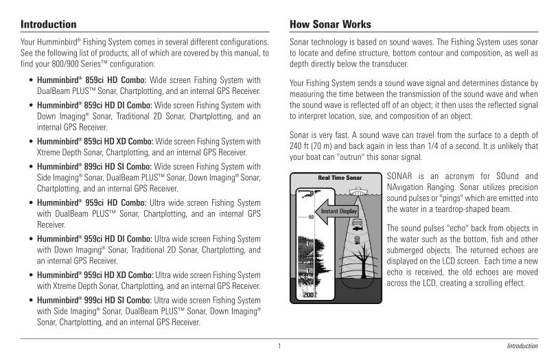
Your Humminbird® Fishing System comes in several different configurations.See the following list of products, all of which are covered by this manual, tofind your 800/900 Series™ configuration:
• Humminbird® 859ci HD Combo: Wide screen Fishing System withDualBeam PLUS™ Sonar, Chartplotting, and an internal GPS Receiver.
• Humminbird® 859ci HD DI Combo:Wide screen Fishing System withDown Imaging® Sonar, Traditional 2D Sonar, Chartplotting, and aninternal GPS Receiver.
• Humminbird® 859ci HD XD Combo:Wide screen Fishing System withXtreme Depth Sonar, Chartplotting, and an internal GPS Receiver.
• Humminbird® 899ci HD SI Combo:Wide screen Fishing System withSide Imaging® Sonar, DualBeam PLUS™ Sonar, Down Imaging® Sonar,Chartplotting, and an internal GPS Receiver.
• Humminbird® 959ci HD Combo: Ultra wide screen Fishing Systemwith DualBeam PLUS™ Sonar, Chartplotting, and an internal GPSReceiver.
• Humminbird® 959ci HD DI Combo: Ultra wide screen Fishing Systemwith Down Imaging® Sonar, Traditional 2D Sonar, Chartplotting, andan internal GPS Receiver.
• Humminbird® 959ci HD XD Combo: Ultra wide screen Fishing Systemwith Xtreme Depth Sonar, Chartplotting, and an internal GPS Receiver.
• Humminbird® 999ci HD SI Combo: Ultra wide screen Fishing Systemwith Side Imaging® Sonar, DualBeam PLUS™ Sonar, Down Imaging®Sonar, Chartplotting, and an internal GPS Receiver.
How Sonar Works
Sonar technology is based on sound waves. The Fishing System uses sonarto locate and define structure, bottom contour and composition, as well asdepth directly below the transducer.
Your Fishing System sends a sound wave signal and determines distance bymeasuring the time between the transmission of the sound wave and whenthe sound wave is reflected off of an object; it then uses the reflected signalto interpret location, size, and composition of an object.
Sonar is very fast. A sound wave can travel from the surface to a depth of240 ft (70 m) and back again in less than 1/4 of a second. It is unlikely thatyour boat can "outrun" this sonar signal.
SONAR is an acronym for SOund andNAvigation Ranging. Sonar utilizes precisionsound pulses or "pings" which are emitted intothe water in a teardrop-shaped beam.
The sound pulses "echo" back from objects inthe water such as the bottom, fish and othersubmerged objects. The returned echoes aredisplayed on the LCD screen. Each time a newecho is received, the old echoes are movedacross the LCD, creating a scrolling effect.

2Introduction
When all the echoes are viewed side by side,an easy to interpret "graph" of the bottom, fishand structure appears.
The sound pulses are transmitted at variousfrequencies depending on the application.Very high frequencies (455 kHz) are used forgreatest definition, but the operating depth islimited. High frequencies (200 kHz) arecommonly used on consumer sonar andprovide a good balance between depthperformance and resolution. Low frequencies(83 kHz) are typically used to achieve greaterdepth capability.
The power output is the amount of energygenerated by the sonar transmitter. It iscommonly measured using two methods:
• Root Mean Square (RMS) measures poweroutput over the entire transmit cycle.
• Peak to Peak measures power output at thehighest points.
The benefits of increased power output arethe ability to detect smaller targets at greaterdistances, ability to overcome noise, betterhigh speed performance and enhanced depthcapability.

Introduction3
DualBeam PLUS™ Sonar(DualBeam PLUS™ models only
[859ci HD, 899ci HD SI, 959ci HD, & 999ci HD SI])
The 859ci HD/959ci HD Combo and 899ciHD SI/999ci HD SI Combo Fishing Systemsuse a 200/83 kHz DualBeam PLUS™ sonarsystem with a wide (60°) area of coverage.DualBeam PLUS™ sonar has a narrowlyfocused 20° center beam, surrounded by asecond beam of 60°, expanding yourcoverage to an area equal to your depth. In20 feet of water, the wider beam covers anarea 20 feet wide.
DualBeam PLUS™ sonar returns can beblended together, viewed separately, orcompared side-by-side. DualBeam PLUS™ isideal for a wide range of conditions - fromshallow to very deep water in both fresh andsalt water. Depth capability is affected bysuch factors as boat speed, wave action,bottom hardness, water conditions, andtransducer installation.
Down Imaging® Sonar(Down Imaging® models only [859ci HD DI
and 959ci HD DI])
The 859ci HD DI/959ci HD DI ComboFishing System uses Down Imaging®technology. The Down Imaging®transducer scans the water with razor-thin, high-definition beams. The beamsare wide (side to side) but very thin frontto back.
The Down Imaging® beams can beoperated at two frequencies: 455 kHz(75°) or 800 kHz (45°). Select 455 kHz forthe best overall image quality and depth.Select 800 kHz for the sharpest image.See Down Imaging® X-Press™ Menu:Imaging Frequency for more information.
The transducer also uses conical beams to provide data in traditional 2Dformat (see What’s on the Sonar View). Select 455 kHz for a narrowlyfocused 16° center beam, or select 200 kHz for a wider 28° beam (see SonarMenu Tab: Beam Select).
Depth capability is affected by such factors as boat speed, wave action,bottom hardness, water conditions, and transducer installation.
75 Degree Total Coverage
16°75°
28°455kHz
200kHz
455kHz
45° 800kHz

Introduction 4
High DefinitionSide Imaging® Sonar(Side Imaging® models only
[899ci HD SI and 999ci HD SI only])
The 899ci HD SI/999ci HD SI ComboFishing System uses Side Imaging®sonar to provide a wide yet precise surveyof a large area of water, includingdetailed bottom topography and fish-attracting structure orientation. The SideImaging® transducer returns areprocessed into an image similar to anaerial photograph.
Typically, the Side Imaging® sonar can search an area that is 480 feet wide(240 to each side), with a typical depth performance of 150 feet when theSide Imaging® Sonar frequency is set for 455 kHz. Selecting 800 kHz (999ciHD SI only) produces the sharpest image, but the search area to each sideand the depth capability are limited as compared to the 455 kHz frequency.See What’s on the Side Imaging® Display and Understanding SideImaging® for more information.
The Side Imaging® transducer also provides Down Imaging® views on thescreen, with the same depth limitation of 100 feet. See What’s on theDown Imaging® Display for more information.
Xtreme Depth Sonar(Xtreme Depth Series™ models only [859ci HD
XD and 959ci HD XD])
The 859ci HD XD/959ci HD XD ComboFishing System uses the XD transducer toprovide extreme depth coverage withDualBeam PLUS™ technology.
The Xtreme Depth sonar beams can beoperated at two frequencies: 50 kHz (74°)and 200 kHz (20°). The wide, 50 kHz beamtransmits at a low frequency to providegreater depth coverage, up to 2500 ft (762m). The narrow, 200 kHz center beamtransmits at a high frequency to providemaximum detail at shallower depths.
The DualBeam PLUS™ technology allowsyou to view the sonar returns blendedtogether, separately, or side-by-side (seeSonar Menu Tab: Beam Select and Viewsfor more information).
Depth capability is affected by such factors as boat speed, wave action,bottom hardness, water conditions, and transducer installation.
60°83kHz
20°200kHz
86°455kHz
86°455kHz

QuadraBeam PLUS™ Sonar(with optional-purchase QuadraBeam
PLUS™ transducer)
QuadraBeam PLUS™ sonar provides awide 90° area of coverage.QuadraBeam PLUS™ starts with twofan-shaped 35° 455 kHz Side Structurelocating sonar beams to spot fish, bait,and structure to the left and right of theboat over an area of the bottom that’salways equal to twice your depth.
For a detailed view below the boat,QuadraBeam PLUS™ uses DualBeamPLUS™ technology, with precision 20°and wide 60° beams. QuadraBeamPLUS™ finds more fish faster, and caneven tell you where to put your bait byshowing if fish are to the left, right, ordirectly beneath your boat.
NOTE: Contact our Customer ResourceCenter to determine which accessorytransducers are compatible with yourHumminbird® Fishing System, or visit our Website at humminbird.com.
Universal Sonar 2(compatible w/optional-purchase Minnkota trolling motors)
Your Fishing System supports Universal Sonar 2, a state-of-the-art,integrated and protected transducer that is built into the lower unit ofMinnkota trolling motors. With Universal Sonar 2, all wiring is concealedinside the indestructible composite shaft—out of sight and out of harm’sway, with no clamps, ties, or exposed wires. Universal Sonar 2 features newtemperature sensing and the performance of DualBeam PLUS™ technology(available with all Humminbird® DualBeam PLUS™ models). An expandedview and greater bottom detail gives you a totally new perspective of thewater below, along with optimal sonar performance to help you find fish.
How GPS and Cartography WorkYour Fishing System also supports GPS (Global Positioning System) andchartplotting. It uses GPS and sonar to determine your position, display it ona grid, and provide detailed underwater information.
GPS uses a constellation of satellites thatcontinually send radio signals to the earth. TheGPS receiver receives signals from satellites thatare visible to it. Based on time differencesbetween each received signal, the GPS receiverdetermines its distance to each satellite. Withdistances known, the GPS receivermathematically triangulates its own position.With 5 updates per second, the GPS receiverthen calculates its velocity and bearing.
90° Total Coverage
Bottom Coverage = 2 x Depth
35° 60° 20° 35°455 kHz 455 kHz
83 kHz
200 kHz
Introduction5

Introduction 6
GPS was originally intended for military use; however, civilians may also takeadvantage of its highly accurate position capabilities, typically within +/- 4.5meters, depending on conditions. This means that 95% of the time, the GPSreceiver will read a location within 4.5 meters of your actual position. YourGPS Receiver also uses information from WAAS (the Wide AreaAugmentation System), EGNOS (the European Geostationary NavigationOverlay Service), and MSAS (the MTSAT Satellite Augmentation System)satellites if they are available in your area.
The following GPS functionality is currently supported by the Fishing System:
• View current position
• View current track (breadcrumb trail)
• View precision speed and heading from your GPS receiver
• Save tracks, waypoints, and routes
• Travel a route and navigate from one waypoint to the next.
See Chart View and SD Memory Card Slots: Add Maps to Your FishingSystem for more information.
The Fishing System has a wide variety of configurations
RS 232 (900 Series™ only)1Temperature (900 Series™ only)2Speed (900 Series™ only)3
GPS Receiver
Sonar Transducer with Temperature
67
Power4
1 2
34
5
6
7
NMEA 2000® Module 5

7 Introduction
Fishing System Configuration
The Fishing System has a wide variety of configurations that will influence theinstallation. The RS 232 connector (900 Series™ only) allows you to expandyour Fishing System capabilities. As you expand the configuration, the menuoptions that correspond with the connected accessory will be added to themenu system.
Please read all instructions that are relevant for your configuration beforebeginning the installation process. See the Humminbird® installation guide fordetails.
NOTE: The following accessories are not compatible with your unit:CannonLink™, InterLink™, Remote Sonar Link™ (RSL), SmartCast®,WeatherSense®, and XM WX Satellite Weather®. See our Web site athumminbird.com for the latest compatibility information.
RS 232 Connector (900 Series™ only)Your 900 Series™ unit has a built-in dual RS 232 connector, which can beused with optional-purchase equipment such as AIS (AutomaticIdentification System).
NOTE: Accessories connected to the RS 232 connector require a separate powersource.
NOTE: To purchase a connection cable for an optional-purchase AIS, visit ourWeb site at humminbird.com or contact our Customer Resource Centerat 1-800-633-1468.
RS 232 (900 Series™ only)1Temp/Speed (900 Series™ only)2Power3
32 4
Ethernet
COM (communications)
Transducer
456
1 5 6

8Power On
Ethernet ConnectorYour unit has a built-in Ethernet connector so that you can network twoHumminbird® units. When you connect the units together using theoptional-purchase Humminbird® Ethernet cable, data is shared across thetwo units and additional menu options are added to theMenu System. See the Ethernet Operations Manual for details.
NOTE: The Ethernet cable requires a separate purchase. Visit our Web site athumminbird.com or contact our Customer Resource Center at 1-800-633-1468for details.
Power OnFollow the instructions below to power on your Humminbird® control head.
1. Press the POWER/LIGHT key to power on your Humminbird®control head.
2. When the Title screen is displayed, press the MENU key to accessthe Start-Up Options Menu.
3. If a functioning transducer is connected, Normal operation will beselected automatically, and your Fishing System can be used on thewater. See Start-Up Options Menu for more information.
• If a transducer is not connected and you wait too long to selecta Start-Up Option, the system will default to whichever menu isalready highlighted.
• You can also select Simulator to learn how to use your controlhead and save settings in advance for later use.
4. Quick Setup: If this is the first time the unit has been powered on(after installation or after restoring defaults), the Quick Setup dialogbox will display on the screen. Use the 4-WAY Cursor Control key toset the Language, Water Type, and Max Depth. Press the EXIT keyto close the dialog box.
NOTE: The Quick Setup settings can be changed at any time. See each menuoption in The Menu System for details.
999ci HD SI Combo Title Screen

9 The Control Head, Key Functions
What’s on the Control Head
Your Fishing System user interface is easy to use. A combination of keys,different views, and situation-specific, customizable menus allows you tocontrol what you see on the color display. Refer to the following illustration,and see Key Functions, Views, and The Menu System for more information.
*Your control head will have one of the INFO keys shown here .Both keys function in the same way.
Key Functions
Your Fishing System has a set of easy to use keys that give you flexibility andcontrol over your fishing experience.
POWER/LIGHT Key
The POWER/LIGHT key is used to power the Fishing Systemon and off. You can also use the POWER/LIGHT key to adjustthe backlight and contrast of the display.
Power On: Press the POWER/LIGHT key to power on the unit. When the Titlescreen is displayed, press the MENU key to access the Start-Up OptionsMenu.
Power Off: Press and hold the POWER/LIGHT key for 3 seconds. A messagewill appear to indicate how many seconds there are until shutdown occurs.To ensure that shutdown occurs properly and any menu settings will besaved, your Fishing System should always be turned off using thePOWER/LIGHT key.
Adjust the Backlight or the DisplayBackground Color: Press the POWER/LIGHTkey to access the Light and Backgroundsubmenu. Use the 4-WAY Cursor Control keyto select Light or Background, and then usethe LEFT or RIGHT Cursor key to change thesettings. Press EXIT to exit the Light andBackground submenu.
NOTE: Your control head will start up with the backlight on and willautomatically turn it off to conserve power.
Screen Menu Key1 7ZOOM (+/-) Keys GOTO Key2 8View Key Exit Key3 94-Way Cursor Control Key VIEW PRESET Keys4 10Info Key* Power/Light Key5MARK Key6
11
1
2
56
4
7
3
9
10
12
11
SD Card Slot 12
8
10Key Functions
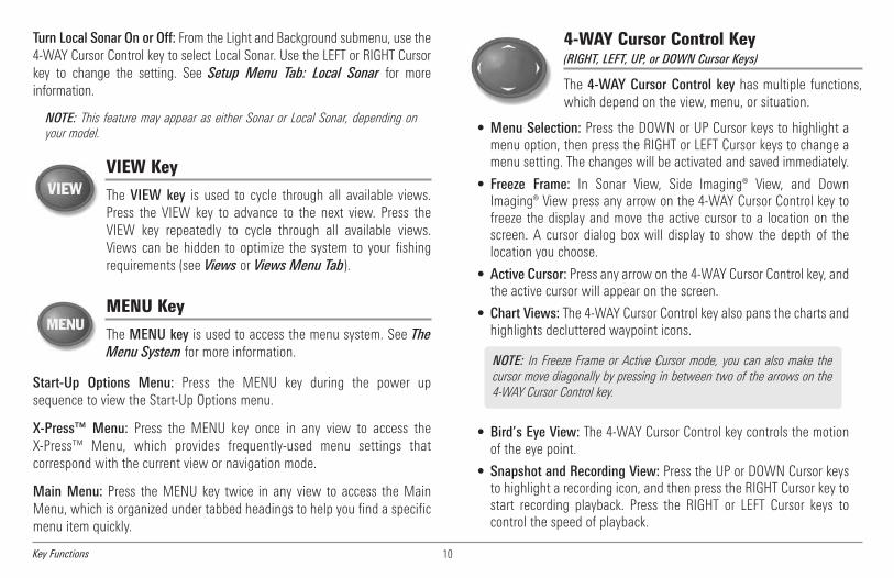
Turn Local Sonar On or Off: From the Light and Background submenu, use the4-WAY Cursor Control key to select Local Sonar. Use the LEFT or RIGHT Cursorkey to change the setting. See Setup Menu Tab: Local Sonar for moreinformation.
NOTE: This feature may appear as either Sonar or Local Sonar, depending onyour model.
VIEW Key
The VIEW key is used to cycle through all available views.Press the VIEW key to advance to the next view. Press theVIEW key repeatedly to cycle through all available views.Views can be hidden to optimize the system to your fishingrequirements (see Views or Views Menu Tab).
MENU Key
The MENU key is used to access the menu system. See TheMenu System for more information.
Start-Up Options Menu: Press the MENU key during the power upsequence to view the Start-Up Options menu.
X-Press™ Menu: Press the MENU key once in any view to access theX-Press™ Menu, which provides frequently-used menu settings thatcorrespond with the current view or navigation mode.
Main Menu: Press the MENU key twice in any view to access the MainMenu, which is organized under tabbed headings to help you find a specificmenu item quickly.
4-WAY Cursor Control Key(RIGHT, LEFT, UP, or DOWN Cursor Keys)
The 4-WAY Cursor Control key has multiple functions,which depend on the view, menu, or situation.
• Menu Selection: Press the DOWN or UP Cursor keys to highlight amenu option, then press the RIGHT or LEFT Cursor keys to change amenu setting. The changes will be activated and saved immediately.
• Freeze Frame: In Sonar View, Side Imaging® View, and DownImaging® View press any arrow on the 4-WAY Cursor Control key tofreeze the display and move the active cursor to a location on thescreen. A cursor dialog box will display to show the depth of thelocation you choose.
• Active Cursor: Press any arrow on the 4-WAY Cursor Control key, andthe active cursor will appear on the screen.
• Chart Views: The 4-WAY Cursor Control key also pans the charts andhighlights decluttered waypoint icons.
• Bird’s Eye View: The 4-WAY Cursor Control key controls the motionof the eye point.
• Snapshot and Recording View: Press the UP or DOWN Cursor keysto highlight a recording icon, and then press the RIGHT Cursor key tostart recording playback. Press the RIGHT or LEFT Cursor keys tocontrol the speed of playback.
NOTE: In Freeze Frame or Active Cursor mode, you can also make thecursor move diagonally by pressing in between two of the arrows on the4-WAY Cursor Control key.

11 Key Functions
VIEW PRESET Keys
The VIEW PRESET keys are used to save your three favoriteviews for quick retrieval. Instead of using the VIEW key tocycle through all the views to find the one you want, you canprogram the VIEW PRESET keys to display a specific viewimmediately. See Views for more information.
EXIT Key
The EXIT key has multiple functions, which depend on thesituation:
• If an alarm is sounding, press the EXIT key to cancel the alarm.
• If a menu tab is selected, press the EXIT key to exit the menu modeand return to the view.
• If a menu is active, press the EXIT key to return to the previous levelin the menu system.
• From any view, press the EXIT key to cycle through the availableviews in reverse order.
• If Freeze Frame is active, press the EXIT key to return to a scrollingdisplay.
• If the Cursor is active, press the EXIT key to remove the cursor fromthe display.
INFO Key
Press the INFO key while in Bird's Eye, Chart, or Combo Viewto display information about objects that are near an activecursor. If the cursor is not active, the Chart Info submenu willbe displayed. See Views: Viewing Cartography for moreinformation.
NOTE: Your control head will have one of the INFO keys shownhere. Both keys function in the same way.
MARK Key
Press theMARK key while in any view to mark the position ofa waypoint. The MARK key function is available if the GPSreceiver is connected.
• Active Cursor: The waypoint will be marked at the cursor location.
• Without Active Cursor: The waypoint will be marked at the boatlocation.
• If Screen Snapshot is active, a waypoint will be created, and ascreen snapshot will also be saved to the optional-purchase SD card(see Views: Snapshot and Recording View). Navigation is notaffected by the Screen Snapshot feature.
NOTE: If Screen Snapshot is enabled but there is not a GPS receiverconnected, pressing the MARK key will capture the screen image and displayan error saying that a GPS position fix is required to create a waypoint.
NOTE: You must have an optional-purchase SD card installed for the screensnapshot feature to work.

12Key Functions, SD Memory Card Slots
GOTO KeyThe GOTO key has multiple functions, which depend on thesituation.
• Active Cursor: Press the GOTO key while in any view to create awaypoint and start navigation towards that waypoint.
• Without Active Cursor: Press the GOTO key to display the savedwaypoints list, and then highlight a waypoint. Press the RIGHTCursor key to begin navigation.
• Man Overboard: Press and hold the GOTO key for more than 1.5seconds to activate the Man Overboard (MOB) function. Once MOBis activated, any current navigation will be cancelled and the currentroute will be discarded without notification (see Man Overboard(MOB) Navigation).
ZOOM (+/-) Keys
The Zoom keys function in different ways which depend onthe view displayed.• Navigation Views or the Sonar Zoom View: Press the+/- ZOOM key to change the scale of the view to appearcloser or farther away.
• Side Imaging® View or Down Imaging® View: Use the4-WAY Cursor Control key to move the active cursor to aposition on the screen. Press the + ZOOM key to magnifyyour selection. Press the -Zoom key to decrease the scale.
NOTE: The cursor must be active for the zoom feature to work in the SideImaging® or Down Imaging® View.
SD Memory Card SlotsThe two SD memory card slots on yourcontrol head can be used with SD memorycards (optional-purchase required) to adddetailed charts to your Fishing System,update your Fishing System software, orexport navigation data from your FishingSystem.
To insert an SD memory card:
1. Remove the SD memory card slot cover.
2. Position the SD memory card so that the label faces the left side of theunit, and insert the card into the slot. Press down on the card until itclicks into place.
3. Close the slot cover and turn the knob just 1/4 of a turn to close. DoNOT overtighten, as this will not improve water resistance and maydamage the cover.
4. To Remove: Press the SD memory card into the slot and then release.The card will eject, and you can then pull the card from the slot.
NOTE: Do not leave the SD slot cover open. The slot cover should always beclosed to prevent water damage to the unit.
NOTE: The SD Memory Cards require a separate purchase. For moreinformation, visit our Web site at humminbird.com or contact our CustomerResource Center at 1-800-633-1468.
Inserting an SD Cardinto the Card Slot
13 SD Memory Card Slots
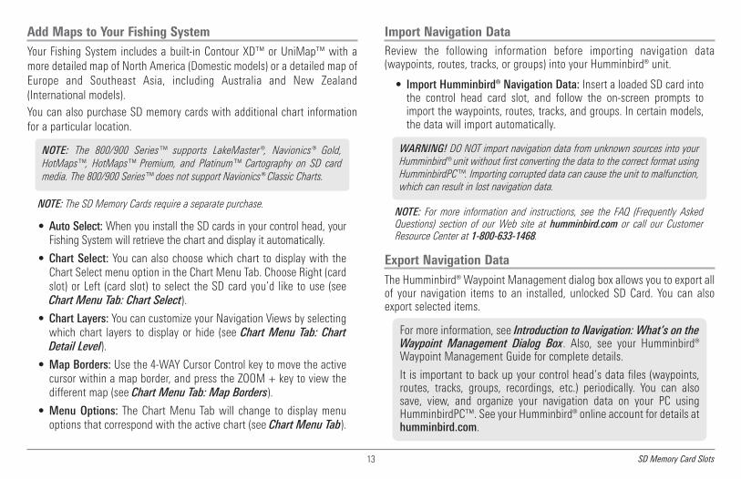
Add Maps to Your Fishing SystemYour Fishing System includes a built-in Contour XD™ or UniMap™ with amore detailed map of North America (Domestic models) or a detailed map ofEurope and Southeast Asia, including Australia and New Zealand(International models).You can also purchase SD memory cards with additional chart informationfor a particular location.
NOTE: The SD Memory Cards require a separate purchase.
• Auto Select:When you install the SD cards in your control head, yourFishing System will retrieve the chart and display it automatically.
• Chart Select: You can also choose which chart to display with theChart Select menu option in the Chart Menu Tab. Choose Right (cardslot) or Left (card slot) to select the SD card you’d like to use (seeChart Menu Tab: Chart Select).
• Chart Layers: You can customize your Navigation Views by selectingwhich chart layers to display or hide (see Chart Menu Tab: ChartDetail Level).
• Map Borders: Use the 4-WAY Cursor Control key to move the activecursor within a map border, and press the ZOOM + key to view thedifferent map (see Chart Menu Tab: Map Borders).
• Menu Options: The Chart Menu Tab will change to display menuoptions that correspond with the active chart (see Chart Menu Tab).
Import Navigation DataReview the following information before importing navigation data(waypoints, routes, tracks, or groups) into your Humminbird® unit.
• Import Humminbird® Navigation Data: Insert a loaded SD card intothe control head card slot, and follow the on-screen prompts toimport the waypoints, routes, tracks, and groups. In certain models,the data will import automatically.
NOTE: For more information and instructions, see the FAQ (Frequently AskedQuestions) section of our Web site at humminbird.com or call our CustomerResource Center at 1-800-633-1468.
Export Navigation DataThe Humminbird® Waypoint Management dialog box allows you to export allof your navigation items to an installed, unlocked SD Card. You can alsoexport selected items.
For more information, see Introduction to Navigation: What’s on theWaypoint Management Dialog Box. Also, see your Humminbird®Waypoint Management Guide for complete details.
It is important to back up your control head’s data files (waypoints,routes, tracks, groups, recordings, etc.) periodically. You can alsosave, view, and organize your navigation data on your PC usingHumminbirdPC™. See your Humminbird® online account for details athumminbird.com.
WARNING! DO NOT import navigation data from unknown sources into yourHumminbird® unit without first converting the data to the correct format usingHumminbirdPC™. Importing corrupted data can cause the unit to malfunction,which can result in lost navigation data.
NOTE: The 800/900 Series™ supports LakeMaster®, Navionics® Gold,HotMaps™, HotMaps™ Premium, and Platinum™ Cartography on SD cardmedia. The 800/900 Series™ does not support Navionics® Classic Charts.

14SD Memory Card Slots
To export all navigation data:
Use the following instructions to export all of the control head’s waypoints,routes, tracks, and groups to an installed, unlocked SD card.
1. Insert an unlocked SD card into the SD card slot.
2. Open the Waypoint Management Dialog Box: Press the MENU keytwice. Press the RIGHT Cursor key until the Navigation tab is selected.Select Waypoints, Routes, Tracks. Press the RIGHT Cursor key.
3. Select Options > Select All and... > Export.
4. Follow the on-screen instructions to confirm or cancel the export.
To export selected navigation items:
Use the following instructions to select and export specific waypoints,routes, tracks, and groups to an installed, unlocked SD card.
1. Insert an unlocked SD card into the SD card slot.
2. Open the Waypoint Management Dialog Box: Press the MENU keytwice. Press the RIGHT Cursor key until the Navigation tab isselected. Select Waypoints, Routes, Tracks. Press the RIGHT Cursorkey.
3. From a selected group directory in the Waypoint Managementdialog box, select Options > Select Multiple and... > Export.
4. Select Items: Press the UP or DOWN Cursor keys to scroll throughthe waypoints, routes, tracks, and groups. Press the RIGHT Cursorkey to select an item. Repeat as needed.
5. Confirm Export: When you are finished selecting items, press theEXIT key to select Export Selected. Press the RIGHT Cursor key andfollow the on-screen instructions to confirm or cancel the export.
NOTE: If an SD memory card is not installed, an error message will be displayed.Insert the SD memory card and try again.
NOTE: The SD memory cards and USB Memory Card Reader require separatepurchases. The USBMemory Card Reader accessory can be used in conjunction withyour personal computer to view and organize your exported navigation data. Visit ourWeb site at humminbird.com or contact our Customer Resource Center at1-800-633-1468 for more information.
15 SD Memory Card Slots
Update SoftwareSet up an online account at humminbird.com so that you will receive thelatest Humminbird® news and software upgrades for your Fishing System.You can also download HumminbirdPC™ from your account, which allowsyou to manage your waypoints, routes, and tracks on your personalcomputer.
Required Equipment: Personal computer with Internet access, a formattedSD memory card, and USB Memory Card Reader.
To update the control head software:
1. Install a formatted SD memory card into the card reader connectedto your PC.
2. Register your Fishing System: Log on to humminbird.com. Click MyAccount. Set up a new account.
3. Download: From My Account\My Profile\My Equipment, click thefile name of the latest software update (unit name [version #]).
• Read the instructions in the dialog box and click Download.
• Follow the prompts to save the software file directly to theSD Card.
4. Install the SD card with the updated software file into the controlhead card slot.
5. Power on your Fishfinder. The control head will recognize the newsoftware and run through a series of prompts to confirm softwareinstallation.
NOTE: It is important to back up your control head’s data files (waypoints,routes, tracks, groups, recordings, etc.) periodically. Data files should also besaved to your PC before restoring the unit’s defaults or updating the software.See Export Navigation Data and Snapshot and Recording View for moreinformation. Also, contact our Customer Resource Center with any questions.

16What’s on the Sonar Display
What’s on the Sonar Display
The Fishing System can display a variety of useful information about the area under and adjacent to your boat, including the following items:
Sonar Color Bar - Color spectrumindicating low to high sonar intensityreturns, where red indicates high intensityand white indicates low intensity.
Depth -Water depth; can be set to alarm when the water becomes too shallow.
Temperature - Water surface temperature.
1
6Timer - Elapsed time with Speed accessory or GPS Receiver.2Distance - Distance traveled with Speed accessory or GPS Receiver.3Average Speed - Average speed reading with Speed accessory or GPS Receiver.4
Thermoclines - Layers of water withdifferent temperatures that appear atdifferent depths and different times of theyear. A thermocline typically appears as acontinuous band of many colors movingacross the display at the same depth.
8
Voltage - Power supplied to the control head.
Bait Ball
5
9
RTS (Real Time Sonar) Window™
1011
4
1
2
3
5
6
7
Second Sonar Return - When the sonarsignal bounces between the bottom and thesurface of the water and back again. Usethe appearance of the second return todetermine bottom hardness. Hard bottomswill show a strong second return, while softbottoms will show a very weak one or noneat all.
12
89
10
11
12
Triplog
Triplog
Speed - If a Speed accessory or GPS Receiver is connected,the Fishing System can display the speed of the boat, andcan keep a triplog of nautical or statute miles traveled.
7
Cursor - Available in Freeze Frame and canbe positioned in the Sonar View to providedepth of a sonar retun and bottom depthbelow the cursor. The Latitude andLongitude of the cursor position, thedistance to travel to the cursor position, andthe bearing to the cursor position areshown with a connected GPS Receiver.Cursor information is displayed at the top ofthe screen.
13
13

17 What’s on the Sonar Display
Understanding the Sonar DisplayIt is important to understand thesignificance of the display. The display doesNOT show a literal 3-dimensionalrepresentation of what is under the water.Each vertical band of data received by thecontrol head and plotted on the displayrepresents something that was detected bya sonar return at a particular time. As boththe boat and the targets (fish) may bemoving, the returns are only showing aparticular segment of time when objectswere detected, not exactly where thoseobjects are in relation to other objectsshown on the display.
The returned sonar echoes are displayed on the screen. As a new echo isreceived, the historical data scrolls left across the display.
Real Time Sonar (RTS™) WindowA Real Time Sonar (RTS™) Window appears on the right side of the displayin the Sonar Views. The RTS Window™ always updates at the fastest ratepossible for depth conditions and shows only the returns from the bottom,structure and fish that are within the transducer beam. The RTS Window™plots the depth and intensity of a sonar return. (See Sonar Menu Tab: RealTime Sonar (RTS™) Window).
TheNarrow RTSWindow™indicates the sonar intensitythrough the use of colors.Red indicates a strong returnand blue indicates a weakreturn. The depth of thesonar return is indicated bythe vertical placement of thereturn on the display depthscale.
The Wide RTS Window™indicates the sonar intensitythrough the use of a bargraph. The length of theplotted return provides anindication of whether thereturn is weak or strong. Thedepth of the sonar return isindicated by the verticalplacement of the return onthe display depth scale.
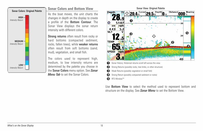
Sonar Colors and Bottom ViewAs the boat moves, the unit charts thechanges in depth on the display to createa profile of the Bottom Contour. TheSonar View displays the sonar returnintensity with different colors.
Strong returns often result from rocky orhard bottoms (compacted sediment,rocks, fallen trees), while weaker returnsoften result from soft bottoms (sand,mud), vegetation, and small fish.
The colors used to represent high,medium, to low intensity returns aredetermined by the palette you choose inthe Sonar Colors menu option. See SonarMenu Tab to set the Sonar Colors.
Use Bottom View to select the method used to represent bottom andstructure on the display. See Sonar Menu to set the Bottom View.
HIGHIntensity Return
MEDIUMIntensity Return
LOWIntensity Return
Sonar Colors: Original PaletteSonar View: Original Palette
Sonar History: Historical returns scroll left across the view.1Strong Returns (possibly rocks, tree limbs, or other structure)2Weak Returns (possibly vegetation or small fish)3Strong Return (possibly compacted sediment or rocks)4RTS Window™5
1
4
5
2
3
18What’s on the Sonar Display

19 What’s on the Sonar Display
Structure ID™ represents weak returns in blue and strong returns in redwhen Sonar Colors is set to Original. If the Sonar Colors palette is changed,the Structure ID™ will display the strongest return as specified by thepalette. See Sonar Menu Tab: Sonar Colors for more information.
WhiteLine™ highlights the strongest sonar returns in white, resulting in adistinctive outline. This has the benefit of clearly defining the bottom on thedisplay.
SwitchFire®SwitchFire® controls how the sonar returns are displayed in the SonarViews. SwitchFire® settings are available in the Sonar Menu Tab.
To see the maximum sonar information available within the transducer beamso more fish arches and better jig tracking are shown, choose Max Mode.
To see less clutter and more fish size accuracy interpreted from thetransducer beam, choose Clear Mode. See Sonar Menu Tab: SwitchFire® formore information.
Freeze Frame and Active CursorFreeze Frame & Active Cursor - Press any arrow on the 4-WAY CursorControl key, and the screen will freeze and a cursor will be displayed. Use the4-WAY Cursor Control key to move the cursor over a sonar return, and thedepth of the sonar return will be displayed at the top of the screen in thecursor dialog box.
The RTS Window™ continues to update in Freeze Frame. To return to ascrolling display and exit Freeze Frame, press the EXIT key. Freeze Frame isavailable in the Sonar, Split Sonar, and Sonar Zoom Views.
Instant Image UpdateInstant Image Update - You can change a variety of sonar menu settings(such as Sensitivity or Upper Range), and the adjustments will be showninstantly on the screen.

20What’s on the Side Imaging® Display
What’s on the Side Imaging® Display (Side Imaging® models only [899ci HD SI and 999ci HD SI])Side Imaging® displays a number of easily recognizable features that allow for accurate interpretation of bottom contour and structure. For Side Imaging®, thebottom composition determines the intensity of the sonar return. For example, rock and gravel provide a clearer sonar return than mud and sand because of theirrelative density. Upward slopes that face the transducer reflect sonar better than downward slopes that face away from the transducer. You can find a number ofeasily recognizable features on the Side Imaging® display that allow for accurate interpretation of bottom contour and structure, including the following items:
Water column - Shows the relative depth of the water under theboat at a given time. Variations in the width of the water columnshow variations in the distance to the bottom as the boat passesover.
Shadows - Result from a lack of reflected sonar from a particulararea and can be more valuable for interpretation than the sonarreflected by the object itself. Use shadows to help you see theimage in 3 dimensions, oriented in space. You can gain insightinto the actual shape of an object, or the depth to which it hassunk into the bottom, through shadows on the display. Objectsstanding on the bottom cast a sonar shadow. The longer theshadow, the taller the object. Fish also cast shadows. You canuse the shadow to interpret how close the fish is to the bottom.
Side Imaging® Range - Images shown on the right side of thescreen are located on the right side of your boat, and imagesshown on the left side of the screen are located on the left sideof your boat. In this illustration, the sonar is pinging 148 feeton each side.
Topography Changes - The light part of the screen showswherethe beam is hitting hard bottom or rising terrain. The dark part ofthe screen indicates soft bottom (sand, mud) or descendingterrain.
Top of the Display - Information from the side beams aredisplayed at the top of the screen. As new information isreceived, the historical data scrolls down the screen. For themost current information, watch the top of the screen.
Clouded Area - May indicate a bait ball and White Streaksmay indicate fish.
Freeze Frame & Zoom - Use the 4-WAY Cursor Control key tomove the cursor to an area on the screen, and press theZOOM+ key to see the sonar returns in greater detail.
Temperature -Water surface temperature.
Voltage - Power supplied to the control head.
Speed - If a Speed accessory or GPS Receiver isconnected, the Fishing System can display thespeed of the boat, and can keep a triplog ofnautical or statute miles traveled.
Bottom Return
Distance - Distance traveled with Speed accessory or GPS Receiver.
Average Speed - Average speed reading with Speed accessory or GPS Receiver.
Timer - Elapsed time with Speed accessory or GPS Receiver.
Depth -Water depth; can be set to alarm when the water becomes too shallow.
1
3
6
7
6
51234Triplog
7
8
4
5 8
Triplog
10
11
10
912
1214
15
13
14
15
9
2
13
11

21 What’s on the Side Imaging® Display
Understanding the Side Imaging® DisplayIt is important to understand how Side Imaging® technology produces thedisplay. The images you see on the display are produced using sonartechnology. The special transducer projects three distinct beams – one beamfacing down and two beams pointing out to the side.
• Down Beam is aimed directly below the boat and provides conicalcoverage.
• Side Beams are aimed at right angles to the path of the boat. Theside beam coverage is very thin from front to back, yet very wide topto bottom. The narrow aspect (front to back) of the beam illuminatesa small strip of the bottom perpendicular to the direction of the boat.
Each time the unit pings, a strip of data representing all the echoesreceived by the transducer are put together on the display to formthe image that you see.
The rows closest to the boat icon at the top of the view are themost recent sonar data. The information is scrolled down the screenas new data, drawn at the top of the screen, becomes available.
The main benefit of Side Imaging® sonar to anglers is that it provides anoverall survey of a large area of water. This gives you a better understandingof the bottom topography and how structure is oriented for more efficientfishing.
Saltwater anglers pick up precise details of popular fishing structure likewrecks, reefs, humps and drop-offs, as well as being able to spot bait ballsin open water. Freshwater anglers can see fish-attracting structure such astimber, stumps, rocks and creek beds.
Side Imaging®sonar echoes arefirst displayed atthe top of thescreen, andhistorical datascrolls down thedisplay as newinformation isreceived.
Side Imaging® Representation
As the unit pings, a strip of data is displayed at the top of the Side Imaging® view.

22What’s on the Side Imaging® Display
Side Imaging® Frequencies and CoverageSide Imaging® sonar uses two very precise sonar beams that are directed toeither side of the boat. The beams “illuminate” the bottom contour,structure, and fish, and the results are displayed in a “picture-like” image onthe screen.
• 899ci HD SI Frequencies: The side beams are operated at 455 kHz.Your Side Imaging® transducer also provides DualBeam PLUS™ at200/83 kHz.
• 999ci HD SI Frequencies: The side beams can be operated at one oftwo frequencies: 455 kHz or 800 kHz. Your Side Imaging® transduceralso provides DualBeam PLUS™ at 200/83 kHz. Selecting 800 kHzproduces the sharpest image, while selecting 455 kHz providesgreater bottom coverage area.
• Side Imaging® Beams are extremely narrow from front to back, andprovide “thin slices” of the bottom for high resolution imaging.
• Side Imaging® Range: 240 feet to each side, with a total sidecoverage of 480 feet, with a depth limitation of 150 feet, dependingon the contour of the bottom and when the side beam frequencyselection is set to 455 kHz.
800 kHz provides highest resolution with 130° total beam width (999ci HD SI)
455 kHz provides maximum coverage with 180° total beam width

23 What’s on the Side Imaging® Display
For Best PerformanceUse the following tips and examples to help you interpret the Side Imaging®display.
Boat speed: Side Imaging® is best performed at boat speeds between 2 to 6mph. If the boat is stationary, the same information is displayed over andover. If the boat is moving very quickly, there will be gaps between the stripsof information. The best boat speed to use will depend on the side rangeselected. Slower speeds are good for longer ranges, while faster speeds canbe used at shorter ranges.
Boat navigation: It is important to understand that when the boat turns,successive beam strips to one side will begin to overlap and the strips on theother side will fan out, providing some distortion to the image. Because ofthis, the best imaging performance is produced by straight line navigationand minimal side-to-side boat motion (i.e. wave induced, etc.) This applies tonavigation by either the main engine or the trolling motor. Minimize turningtime and avoid wave action that induces large side-to-side rocking of theboat. For example, if there is a lot of wave activity, try to move the boat sothat it is perpendicular to the waves instead of parallel with the waves inorder to minimize the side-to-side rocking of the boat.
Beam Coverage:When there is an area directly under the boat that does nothave SI beam coverage, this area will be covered by the standard 200/83 kHzdown-looking beam and displayed in the Sonar views. The net effect of this,on the display, is that a single object may appear as two separate entities,when in reality, it is one continuous object. See Submerged Bridge: A CloserPerspective and the Submerged Bridge: Alternative Perspectiveillustrations for examples of this.
See humminbird.com for a side imaging sonar tutorial and additionalinformation.
Side Imaging® Tips
Boat speed: 2 to 6 mph
Straight line navigation
Minimum turning time and wave turbulence

24What’s on the Side Imaging® Display
On the Water Interpretation Submerged Ravine with Timber
Possible drop off1
1
Submerged Bridge: A Closer Perspective
Submerged Bridge1
1
Submerged timber2
Submerged tree 3Submerged ravine 4
2
3
4
New bridge pilings1Creek channel2Submerged bridge3
Submerged Bridge, Creek Channel, and New Bridge Piling
12
3
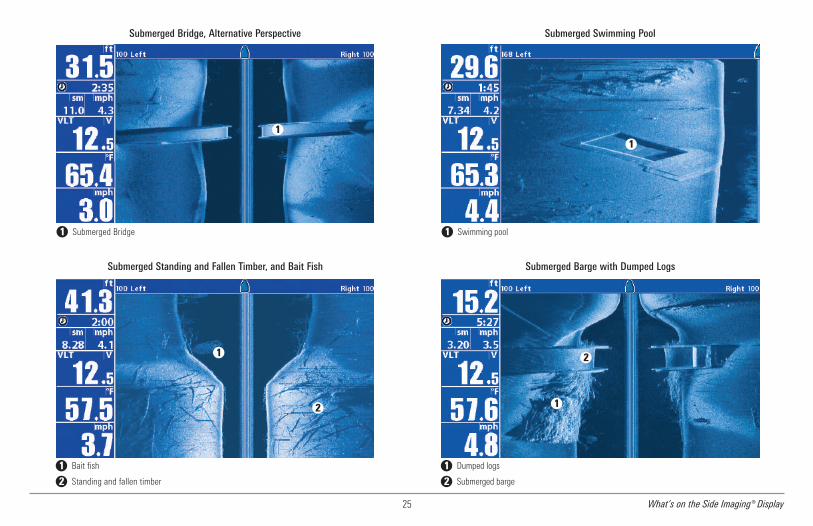
25 What’s on the Side Imaging® Display
Submerged Swimming Pool
Swimming pool1
1
Submerged Barge with Dumped Logs
1
Dumped logs1Submerged barge2
2
Submerged Bridge, Alternative Perspective
Submerged Bridge1
1
Submerged Standing and Fallen Timber, and Bait Fish
1
Bait fish1Standing and fallen timber2
2

26What’s on the Down Imaging® Display
What’s on the Down Imaging® Display (859ci HD DI, 959ci HD DI, 899ci HD SI, and 999ci HD SI only)Down Imaging® uses unique sonar technology to provide information about the area directly below your boat. The razor-thin, high- definition profiling beamsproduce the detailed sonar data that you see on the display. Down Imaging® reveals a variety of recognizable features so that you can interpret the structureand bottom contour, including the following items:
NOTE: Entries in this view that list (with Temp/Speed or GPS Receiver) are available if either device is connected to the 800/900 Series™ Fishing System. If both devices areconnected, then only the information from the GPS receiver will be displayed on the view.
3
Freeze Frame & Zoom - Use the 4-WAY Cursor Control key tomove the cursor to an area on the screen, and press theZOOM+ key to see the sonar returns in greater detail.
Topography Changes - The light part of the display showswhere the beam is hitting hard bottom or rising terrain. Thedark part of the display indicates soft bottom (sand, mud) ordescending terrain.
Depth - Water depth can be set to alarm when the water becomes too shallow.
Timer - Elapsed time with Speed accessory or GPS Receiver.
Structure
2Distance - Distance traveled with Speed accessory or GPS Receiver.
Average Speed - Average speed reading with Speed accessory or GPS Receiver.4
Shadows - Result from a lack of reflected sonar from aparticular area and can be as valuable for interpretation thanthe sonar reflected by the object itself. Use shadows to helpyou see the image in 3 dimensions, oriented in space. You cangain insight into the actual shape of an object, or the depth towhich it has sunk into the bottom, through shadows on thedisplay. Objects standing on the bottom cast a sonar shadow.The longer the shadow, the taller the object. Fish also castshadows. You can use the shadow to interpret how close thefish is to the bottom.
9
Upper Range5
4
1
2
3
7
Triplog
Triplog
10
12
13
8
Clouded Area may indicate a bait ball and White Streaks mayindicate fish.
Lower Range6
Speed - If a GPS Receiver or Temp/Speed accessory isconnected, the Fishing System can display the speed of theboat and can keep a Triplog of nautical or statute milestraveled.
7
Bottom Return - Use the appearance of the bottom return todetermine bottom hardness. Rock and gravel provide a clearersonar return than mud and sand because hard objects reflectsonar better than soft objects.
11
1
3
13
11
12
5
6
10
8
9

27 What’s on the Down Imaging® Display
Understanding theDown Imaging® DisplayThe images you see on the DownImaging® display are producedusing sonar technology. Each timethe unit pings, a strip of datarepresenting all the echoesreceived by the transducer are put
together on the display to form the image that you see. Like traditional 2DSonar, the sonar history scrolls left across the screen.
Interpreting the DisplayDown Imaging® beams “illuminate” the bottom contour, structure, and fish.The beams are wide (side to side) but very thin front to back.
Use the light and dark parts of the display to interpret the objects under yourboat as follows:
• Dark shades represent soft returns (mud, sand) or descendingterrain.
• Light shades represent denser terrain (timber, rocks) or rising terrain.A very hard bottom may appear as white on the display.
• White Streaks or Clouds may represent fish on the display.
• Shadows are not caused by light but by the lack of a sonar return.Objects standing on the bottom cause a sonar shadow to appear onthe display. The longer the shadow, the taller the object. Fish mayalso cast shadows. You can use the shadow to interpret where thefish or object is located in relation to the bottom.
Down Imaging® SensitivityUse Down Sensitivity to control how the sonar returns appear on thedisplay. Increase the sensitivity to reveal weaker returns that may be ofinterest, especially in very clear water or greater depths. Decrease thesensitivity to eliminate the clutter from the display that is sometimes presentin murky or muddy water. See the Down Imaging® X-Press™Menu for moreinformation.
Freeze Frame and Active CursorFreeze Frame and Active Cursor - Press any arrow on the 4-WAY CursorControl key, and the screen will freeze and a cursor will be displayed. Use the4-WAY Cursor Control key to move the cursor over a sonar return, and thedepth of the sonar return will be displayed in the cursor dialog box.
Zoom: Use the zoom keys on your control head to see the returns near thecursor location at a higher magnification. See Views: Down Imaging® Viewfor more information.

28Views
Views
The sonar and navigation information from your FishingSystem is displayed on the screen in a variety of easy-to-read views. Many of these views are also available as aCombo View, which shows two views on the screen at thesame time.
• Default View: See below for the default view when you first powerup your control head.
859ci HD: Sonar View
959ci HD: Sonar/Chart Combo View
859ci HD DI and 959ci HD DI: Chart/Down Combo View
859ci HD XD: Sonar View
959ci HD XD: Sonar/Chart Combo View
899ci HD SI and 999ci HD SI: Chart/Side Combo View
• Available Views: The available Views on your Humminbird® unit willvary with the model and the transducer attached to your control head.See Views Menu Tab and the following pages for more information.
• Next View/Previous View: When you press the VIEW keyrepeatedly, the display cycles through the available views on yourscreen. When you press the EXIT key, the display cycles through theavailable views in reverse order.
• Customize: You can display or hide any view to suit your fishingpreferences. See the following pages for more information abouteach View.
• Views X-Press™ Menu: Press and hold the VIEW key. Usethe 4-WAY Cursor Control key to select a view category(Sonar, Chart, Radar, Data, System) and a view.
The Views X-Press™ Menu allows you to quickly access aview instead of scrolling through the View Rotation.
To customize your view rotation:
You can choose which views are hidden or visible in your view rotation.
1. Press the MENU key twice to access the tabbed Main Menu, thenpress the RIGHT Cursor key until the Views tab is selected.
2. Press the UP or DOWN Cursor keys to select a View.
3. Press the LEFT or RIGHT Cursor keys to change the status of theview from Hidden to Visible or vice versa.
To program each PRESET key:
Another way to access your favorite views quickly is to store them on theVIEW PRESET keys. Instead of using the VIEW key to cycle through everyview to find the one you want, you can program the VIEW PRESET keys todisplay a specific view immediately.
1. Press the VIEW key to cycle to the view you want to store.
2. Press and hold one of the VIEW PRESET keys for several seconds. Achime will indicate that the view has been saved. You can store upto three views, one on each key.

29 Views
To change the Digital Readouts:
Each view displays digital readout information (such as speed or time),which varies with the view selected, the accessory attached, and whetheror not you are navigating. See Setup Menu Tab: Select Readouts for moreinformation about which digital readout windows can be customized.
1. Press the MENU key twice to access the tabbed Main Menu, thenpress the RIGHT Cursor key until the Setup tab is selected.
2. Press the DOWN key to highlight Select Readouts, and press theRIGHT Cursor key to access the Select Readouts submenu.
NOTE: If the Select Readouts option does not appear under the Setup Tab,change the User Mode to Advanced.
3. Press the UP or DOWN Cursor keys to select a Readout position,then press the RIGHT or LEFT Cursor keys to choose what will bedisplayed in that position. To hide the data window, select Off.
Sonar View
Sonar View presents a historical log of sonar returns. The most recent sonarreturns are charted on the right side of the display. As new information isreceived, the historical information scrolls left across the display.
• Upper and Lower Depth Range numbers indicate the distance fromthe surface of the water to a depth range sufficient to show thebottom.
• Depth is automatically selected to keep the bottom visible on thedisplay, although you can adjust it manually as well (see SonarX-Press™ Menu).
• Digital Readouts shown on the display will change based on theSelect Readouts settings or the optional-purchase accessoriesattached (see Setup Menu Tab: Select Readouts).
• Freeze Frame: Use the 4-WAY Cursor Control key to freeze thedisplay and move the cursor over a sonar return. The depth of thesonar return will be displayed at the top of the screen in the cursordialog box.

30Views
NOTE: If the Depth number is flashing, it means that the unit is having troublelocating the bottom. This usually happens if the water is too deep, the transduceris out of the water, the boat is moving too fast, or for any other reason that theunit can’t accurately receive continuous data.
Sonar Zoom View
Sonar Zoom View provides a magnified view of the bottom and structure.The Sonar Zoom View makes it easier to see separate sonar returns thatwould usually be displayed close together, such as those caused by fishsuspended close to the bottom or within structure.
• The Zoom Level, or magnification, is displayed in the top left cornerof the display. Press the + or - ZOOM keys to increase or decrease thezoom level.
• The Zoomed View is displayed on the left side of the screen. As thedepth changes, the zoomed view updates automatically.
• The Full Range View is displayed on the right side of the screen. TheFull Range View includes the Zoom Preview Box, which shows wherethe zoomed view is in relation to the full range view.
• The Upper and Lower Depth Range numbers indicate the high andlow range of the water which is being viewed.
• Digital Readouts shown on the display will change based on theSelect Readouts settings or the optional-purchase accessoriesattached (see Setup Menu Tab: Select Readouts).
• Freeze Frame: Use the 4-WAY Cursor Control key to freeze thedisplay and move the cursor over a sonar return. The depth of thesonar return will be displayed at the top of the screen in the cursordialog box.
Sonar View
Depth Depth below Cursor1 7Triplog Distance to Cursor2 8Temperature Bearing to Cursor3 9Speed RTS Window™4 10Cursor Sonar Color Bar5 11Depth of Cursor Lower Depth Range6 12
1
2
3
4
6 9
5
7 8
10
11
12

31 Views
Split Sonar View
Split Sonar View displays sonar returns from each down beam frequency onseparate sides of the screen. You can use the Split Sonar View to make sideby side comparisons between the sonar returns from both beams.
• DualBeam PLUS™ models (859ci HD, 959ci HD, 899ci HD SI,999ci HD SI) display sonar returns from the 83 kHz wide beam on theleft side of the screen and sonar returns from the 200 kHz narrowbeam on the right side of the screen.
• Down Imaging® models (859ci HD DI, 959ci HD DI) displaytraditional 2D sonar returns from the 455 kHz narrow beam on theleft side of the screen and sonar returns from the 200 kHz wide beamon the right side of the screen.
• Xtreme Depth models (859ci HD XD, 959ci HD XD) display sonarreturns from the 50 kHz wide beam on the left side of the screen andsonar returns from the 200 kHz narrow beam on the right side of thescreen.
• Depth is displayed in the upper left hand corner.
• The Digital Readouts in the Split Sonar View cannot be customized;therefore, information such as water temperature and voltage areunavailable in the Split Sonar View.
• Freeze Frame: Use the 4-WAY Cursor Control key to freeze thedisplay and move the cursor over a sonar return. The depth of thesonar return will be displayed at the top of the screen in the cursordialog box.
Sonar Zoom View
Depth Upper Depth Range, Full Range View1 7Triplog Upper Depth Range, Zoom View2 8Temperature Zoom Preview Box3 9Speed Full Range View4 10Zoomed View Lower Depth Range, Full Range View5 11Zoom Level Lower Depth Range, Zoom View6 12
1
2
3
4
5
6 78
9
10
1112
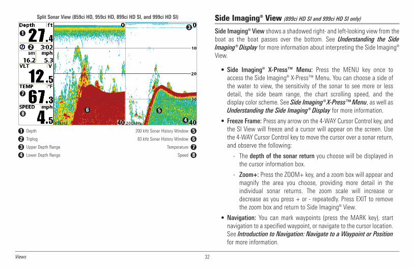
32Views
Side Imaging® View (899ci HD SI and 999ci HD SI only)
Side Imaging® View shows a shadowed right- and left-looking view from theboat as the boat passes over the bottom. See Understanding the SideImaging® Display for more information about interpreting the Side Imaging®View.
• Side Imaging® X-Press™ Menu: Press the MENU key once toaccess the Side Imaging® X-Press™ Menu. You can choose a side ofthe water to view, the sensitivity of the sonar to see more or lessdetail, the side beam range, the chart scrolling speed, and thedisplay color scheme. See Side Imaging® X-Press™Menu, as well asUnderstanding the Side Imaging® Display for more information.
• Freeze Frame: Press any arrow on the 4-WAY Cursor Control key, andthe SI View will freeze and a cursor will appear on the screen. Usethe 4-WAY Cursor Control key to move the cursor over a sonar return,and observe the following:
- The depth of the sonar return you choose will be displayed inthe cursor information box.
- Zoom+: Press the ZOOM+ key, and a zoom box will appear andmagnify the area you choose, providing more detail in theindividual sonar returns. The zoom scale will increase ordecrease as you press + or - repeatedly. Press EXIT to removethe zoom box and return to Side Imaging® View.
• Navigation: You can mark waypoints (press the MARK key), startnavigation to a specified waypoint, or navigate to the cursor location.See Introduction to Navigation: Navigate to a Waypoint or Positionfor more information.
Split Sonar View (859ci HD, 959ci HD, 899ci HD SI, and 999ci HD SI)
Depth 200 kHz Sonar History Window
1
2
56
1 5Triplog 83 kHz Sonar History Window2 6Upper Depth Range Temperature3 7Lower Depth Range Speed4 8
3
4
7
8

33 Views
- Navigation readouts will display at the bottom of the screenwhen navigation starts.
- Boat Icon: When you start navigation, the boat icon at the topof the screen will indicate the direction the boat needs to turnto reach the waypoint. The boat icon color will also change toorange. See Navigation Menu Tab: SI Navigation andIntroduction to Navigation for more information.
Zoom Box
Side Imaging® View, with Active Cursor and Zoom
Depth Water Column1 5Triplog Shadows2 6Water Surface Temperature Topography Changes3 7Speed Bottom Return4 8
9
5
6
7
8
1
2
3
4
9
Shadows
Water Column
Speed
Course
Depth
34
1
2
5
Waypoint the boat is navigating towards
Side Imaging® View (while Navigating)
Topography Changes 6Bottom Return 7
Orange Boat Icon (Navigating) 8
8
4
5
6
7
3
9
9
1
2

34Views
Down Imaging® View(859ci HD DI, 959ci HD DI, 899ci HD SI, and 999ci HD SI only)
Down Imaging® models (859ci HD DI, 959ci HD DI) use the razor-thin,high-definition profiling beams to produce the detailed sonar data that yousee on the display.
Side Imaging® models (899ci HD SI, 999ci HD SI) display the down beamportion of the data from the Side Imaging® beams. The Down Imaging®results are displayed in a “picture-like” image on the screen in 2D format.
Sonar returns are charted on the right side of the display. As newinformation is received, the historical information scrolls left across thedisplay. SeeWhat’s on the Down Imaging® Display for more information.
• Coverage: The Down Imaging® coverage is always very thin front toback, and the side to side width can be adjusted (see Sonar MenuTab: Down Imaging® Beam Width).
• Down Imaging® X-Press™Menu: Press the MENU key once to accessthe Down Imaging® X-Press™ Menu. You can set the sensitivity of thesonar to see more or less detail, the chart scrolling speed, and thedisplay color palette (see Down Imaging® X-Press™ Menu).
• Freeze Frame: Press any arrow on the 4-WAY Cursor Control key, andthe Down Imaging® View will freeze and a cursor will appear on thescreen. Move the cursor over a sonar return, and observe the following:
- The depth of the sonar return you choose will be displayed inthe cursor information box.
- Zoom+: Press the ZOOM+ key, and a zoom box will appear andmagnify the area you choose, providing more detail in theindividual sonar returns. The zoom scale will increase ordecrease as you press + or - repeatedly. Press EXIT to removethe zoom box and return to Down Imaging® View.
Down Imaging® View
Depth Bottom Return1 6Triplog Topography Changes2 7Water Surface Temperature Upper Range3 8Time Lower Range4 9
6
7
1
2
3
4
8
59
Speed5
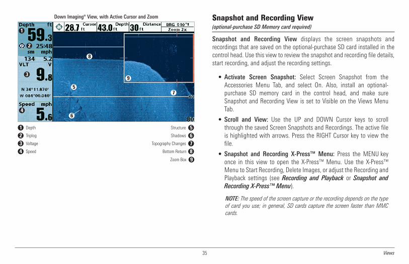
35 Views
Snapshot and Recording View(optional-purchase SD Memory card required)
Snapshot and Recording View displays the screen snapshots andrecordings that are saved on the optional-purchase SD card installed in thecontrol head. Use this view to review the snapshot and recording file details,start recording, and adjust the recording settings.
• Activate Screen Snapshot: Select Screen Snapshot from theAccessories Menu Tab, and select On. Also, install an optional-purchase SD memory card in the control head, and make sureSnapshot and Recording View is set to Visible on the Views MenuTab.
• Scroll and View: Use the UP and DOWN Cursor keys to scrollthrough the saved Screen Snapshots and Recordings. The active fileis highlighted with arrows. Press the RIGHT Cursor key to view thefile.
• Snapshot and Recording X-Press™ Menu: Press the MENU keyonce in this view to open the X-Press™ Menu. Use the X-Press™Menu to Start Recording, Delete Images, or adjust the Recording andPlayback settings (see Recording and Playback or Snapshot andRecording X-Press™ Menu).
NOTE: The speed of the screen capture or the recording depends on the typeof card you use; in general, SD cards capture the screen faster than MMCcards.
Zoom Box
Down Imaging® View, with Active Cursor and Zoom
Depth Structure1 5Triplog Shadows2 6Voltage Topography Changes3 7Speed Bottom Return4 8
9
6
7
8
1
2
3
4
9
5

36Views
NOTE: For snapshots and recordings, the indicator bar has several states: duringrecording, the amount of space remaining on the SD card is indicated on thestatus bar. During playback, the amount of time/memory remaining to play isindicated on the status bar. When a snapshot thumbnail is highlighted, theamount of room remaining on the SD card is indicated.
Screen SnapshotsScreen Snapshots are saved pictures of the view on the screen. The screensnapshot will include the menus, dialog boxes, warnings, and messages thatwere active when the screen snapshot was taken. Saved Screen Snapshotscan be viewed from the Snapshot and Recording View or Chart View.
The Screen Snapshot feature is available when an optional-purchase SDmemory card is installed and Screen Snapshot is On (see Accessories MenuTab: Screen Snapshot).
Make a Screen Snapshot:
1. Activate Screen Snapshotand install an SD card.
2. From any view or cursorlocation you want to capture,press the MARK key. Thescreen will pause while theimage is saved.
A waypoint will also be created at the boat or active cursor location. Thescreen snapshot shares the same file name (.PNG).
Waypoint saved at Cursor Location1Screen Snapshot Confirmation2File Name3
1
2 3
Snapshot and Recording View
Recording icon Amount of recording left to play
1
2
5
6
1 5Snapshot thumbnail Recording mode icons2 6Unavailable icon Amount of recording that has been played3 7Information box Amount of space used for this recording4 8
3
4
7
8
5

37 Views
Delete a Screen Snapshot:
1. From the Snapshot andRecording View, press the UPor DOWN Cursor keys toscroll through the saved filesand highlight a snapshot file.
2. Press the Menu key once,and select Delete Image fromthe X-Press™ Menu.
3. Press the RIGHT Cursor key.
NOTE: Navigation is not affected by the Screen Snapshot feature. Also, if ScreenSnapshot is enabled, but a GPS receiver is not connected, pressing the MARK keywill capture the screen image but an error will display that says a GPS positionfix is required to create a waypoint.
View a saved Screen Snapshotfrom Snapshot and RecordingView:
1. From the Snapshot andRecording View, press the UPor DOWN Cursor keys toscroll through the saved filesand highlight a snapshot file.
2. Press the RIGHT Cursor key.
View a saved Screen Snapshotfrom Chart View:
1. In Chart View, use the 4-WAYCursor Control key to movethe active cursor onto aScreen Snapshot Icon .
When the cursor snaps ontothe Screen Snapshot Icon, athumbnail preview of theScreen Snapshot will bedisplayed on the screen.
2. Press the INFO key, and select View Snapshot.
3. Press the EXIT key to return to Chart View.
Notes about Screen Snapshots:
• A border around the full screen indicates that the view is a savedscreen snapshot and not a “live” view.
• If you press the INFO key, and the snapshot file connected to theicon is not saved on the installed SD card, the Chart Information boxwill display instead of the screen snapshot.
• Use an optional-purchase SD card reader connected to a PC to viewthe saved screen snapshot data files on your optional-purchase SDcard (see humminbird.com for details). You will notice that a .DAT (ora .TXT) file is created for every .PNG screen snapshot. This data file isrequired for viewing the screen snapshots from your control head, sodon’t delete these files.
Screen Snapshot Icon and Waypoint Name1Thumbnail Preview(press the INFO key to view at full size)
2
1
2
Snapshot File Name1Time + Date of Snapshot2Waypoint Position3Highlighted Snapshot File4SD card available storage5
1 2 3
5
4
From Snapshot and Recording View, select DeleteImage from the X-Press™ Menu.
1
1

38Views
Recording and PlaybackThe Recording feature records active sonar information. When the recordingis played back, the views that were active during the recording are availablein Playback. The Recording and Playback feature is available when anoptional-purchase SD card is installed and Screen Snapshot is On (seeAccessories Menu Tab: Screen Snapshot). Saved Recordings can be playedback from the Snapshot and Recording View.
Start recording:
1. From the Snapshot andRecording View, press theMENU key once to open theSnapshot and RecordingX-Press™ Menu.
2. Highlight Start Recording,and press the RIGHT Cursorkey. A waypoint will also becreated at the boat location,and the recording shares thesame file name (.SON).
Stop recording:
1. In any view, press the MENU key once to open the Snapshot andRecording X-Press™ Menu.
2. Highlight Stop Recording and press the RIGHT Cursor key.
Notes about Recording:
• While recording, press the EXIT key to exit the Snapshot andRecording X-Press™ Menu and scroll to a different view. Recordingwill continue.
• The slider bar at the bottom of the Snapshot and Recording Viewshows the recording progress and remaining space on the SD card.
• Pings Per Second: For maximum performance, keep the Pings PerSecond setting on Auto (see Snapshot and Recording X-Press™Menu).
• Viewing saved Screen Snapshots and Recording Playback are notavailable while in recording mode.
Playback a Recording:
1. From the Snapshot andRecording View, press the UPor DOWN Cursor keys toscroll through the saved filesand highlight a savedRecording.
2. Press the RIGHT Cursor key.Recording File Information1Highlighted Recording File2
1
2
From Snapshot and Recording View, select StartRecording from the X-Press™ Menu
1
Slider Bar2
1
2

39 Views
Change Playback Settings:
1. Press the MENU key once toopen the Snapshot andRecording X-Press™ Menu.
2. Use the X-Press™ Menu toadjust the Sonar Recording’sSensitivity, Upper Range,Lower Range, and thePlayback Speed. SeeSnapshot and RecordingX-Press™ Menu for details.
Stop Playback:1. Press the MENU key once to open the Snapshot and Recording
X-Press™ Menu.
2. Highlight Stop Playback, and press the RIGHT Cursor key.
Delete a Recording:1. From the Snapshot andRecording View, press the UPor DOWN Cursor keys toscroll through the saved filesand highlight a savedRecording.
2. Press the Menu key once,and select Delete Recordingfrom the X-Press™ Menu.Press the RIGHT Cursor key.
Notes about Playback:
• “Playback” will flash periodically on the screen to indicate that thecontrol head is playing a saved recording and not a “live” view.
• Navigation is not affected by the Sonar Recording feature, but anyactive navigation is cancelled and thumbnails and icons disappearwhen Playback begins or ends.
• Playback is paused automatically at the end of the recording.
• Freeze Frame: Press the 4-WAY Cursor Control key to pause Playbackand move the Active Cursor to a location on the sonar view. TheCursor dialog box will show the depth and information for thelocation you choose. Press Exit to resume Playback.
• Press the MARK key during Playback to save a Screen Snapshotand/or mark a waypoint in the view or active cursor location youchoose.
From Snapshot and Recording View, selectDelete Recording from the X-Press™ Menu.
1
1
“Playback” indicates the control head is playinga saved recording.
1
Open the X-Press™ Menu to adjustPlayback settings.
2
You can also use Freeze Frame and mark waypoints.
1
2
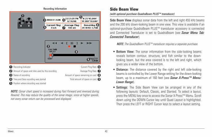
40Views
NOTE: Sonar chart speed is increased during Fast Forward and reversed duringRewind. This may reduce the quality of the sonar image, since at higher speeds,not every sonar return can be processed and displayed.
Side Beam View(with optional-purchase QuadraBeam PLUS™ transducer)
Side Beam View displays sonar data from the left and right 455 kHz beamsand the 200 kHz down-looking beam in one view. This view is available if anoptional-purchase QuadraBeam PLUS™ transducer accessory is connectedand Connected Transducer is set to QuadraBeam (see Sonar Menu Tab:Connected Transducer).
NOTE: The QuadraBeam PLUS™ transducer requires a separate purchase.
• Bottom View: The sonar information from the side-looking beamsreveals bottom contour, structure, and fish similar to the down-looking beam, but the area covered is to the left and right, whichgives you a wider view of the bottom.
• Distance: The distance covered by the right and left side-lookingbeams is controlled by the Lower Range setting for the down-lookingbeam, up to a maximum of 160 feet (see Sonar X-Press™ Menu:Lower Range).
• Settings: The Side Beam View can be arranged in any of thefollowing layouts: Default, Classic, and Slanted. To select a layout,press the MENU key once to access the Sonar X-Press™Menu. Scrolldown using the DOWN Cursor key until Quad Layout is highlighted.Then press the LEFT or RIGHT Cursor keys to select a layout setting.
Recording Information
Recording Indicator Current Ping Rate
1
2
5
6
1 6Amount of space and time used by this recording Average Ping Rate2 7Name of recording Amount of space remaining on card3 8Time and Date recording was started Total amount of space on card4 9Position where recording was started5 10
3 4
78
8
9

41 Views
Default layout: The top portion of the display presents a historical log ofsonar returns from the 200 kHz down-looking sonar beam. New informationin the down beam panel scrolls from right to left. The bottom portion of thedisplay presents a historical log of sonar returns from the 455 kHz right- andleft-looking sonar beams. New information in the side beam panels scrollsfrom the center out.
Classic layout: The top portion of the display presents a historical log ofsonar returns from the 200 kHz down-looking sonar beam. New informationin the down beam panel scrolls from right to left. The bottom portion of thedisplay presents a historical log of sonar returns from the 455 kHz right- andleft-looking sonar beams. New information appears at the top and scrollsdown the display.
Side Beam View, Classic Layout
Depth 200 kHz Sonar History Window
1
5
1 4Temperature2 5
Right Side 455 kHz Sonar History Window 6
3
4
Water Surface Line for 455 kHz Sonar History Windows
2 6
Left Side 455 kHz Sonar History Window3
Side Beam View, Default Layout
Depth 200 kHz Sonar History Window
1
5
1 4Temperature2 5Left Side 455 kHz Sonar History Window Right Side 455 kHz Sonar History Window3 6
3
4
Water Surface Line for 455 kHz Sonar History Windows
2
6

42Views
Slanted layout: This layout is presented as three slanted panelsrepresenting the two 455 kHz side sonar beams and the 200 kHz down-looking sonar beam. New information appears on the right and scrolls to theleft.
Bird’s Eye ViewBird’s Eye View shows a 3D perspective view of the track and the chart’sland contour from a point above and behind the boat (the eye point). As theboat turns, the eye point moves to follow the boat.
• To shift the eye point position so that you can look off to the sides,or even behind the boat: Press the RIGHT or LEFT Cursor keys to turnthe eye point right or left. Press the UP Cursor key to move the eyepoint forward, and press the DOWN Cursor key to move the eye pointbackward.
• Press the EXIT key tomove the eye point back to its original positionbehind and above the boat.
Side Beam View, Slanted Layout
Depth 200 kHz Sonar History Window
1
5
1 4Temperature2 5Left Side 455 kHz Sonar History Window Right Side 455 kHz Sonar History Window3 6
4
Water Surface Line for 455 kHz Sonar History Windows
2
3 6
55
Bird’s Eye View
Depth Speed of Boat1 4Course: Direction the boat is traveling relative to North Reference Land Contours2 5
Boat Icon
1
2
4
5
6
3
6Latitude and Longitude Position of Boat3

43 Views
Chart ViewChart View shows cartography from the built-in Contour XD™, built-inUniMap™, or an optional SD map for the area surrounding your currentposition. The cartography is applied to any standard Chart View or ComboView that displays a chart. The current track (also known as the positionhistory or breadcrumb trail) showing where the boat has been, along withsaved tracks, waypoints, and the current route (when navigating), areoverlaid on the chart.
• Shift/Pan: Use the 4-WAY Cursor Control key to shift/pan the chartto another area.
• Zoom: Press the ZOOM (+/-) keys to zoom in and out.
• Information: Press the INFO key to get information about the chartobjects near the cursor.
Chart View with Active Cursor
Depth Distance to the Cursor1 6Course: Direction the boat is travelingrelative to North Reference.
Bearing to Cursor2 7
Track (Breadcrumb Trail)Cartography3 8
Map ScaleActive Cursor4 9
Latitude and Longitude Position of CursorBoat Icon
5 10
1
2
4
5 6
3
7
8
9
10

44Combo Views
Combo Views
Combo Views display two views (or more) on the screen at the same time.You can perform functions for either side of the view, access the X-Press™Menu, and change the left view display size. The available combo views areshown on the following pages.
Combo Views: Functions
The Combo Views allow you to view and control two views at once. Tochange the settings in a View, the view must be selected as the active side.
• The green arrow points to the active side.
• Active Side: Press the MENU key once and select Active Side fromthe X-Press™ Menu. Choose RIGHT or LEFT to set the active side.
• X-Press™Menu: After you set the Active Side, press the MENU keyonce to access the X-Press™ Menu. The X-Press™ Menu providessettings for the active view, and the display updates immediatelywith your changes.
• Display Size: Press the MENU key once and select Split Position fromthe X-Press™Menu. Split Position allows you to adjust the size of theleft side of the display.
• Active Cursor: Press any arrow on the 4-WAY Cursor Control key, andthe cursor will appear on the active side of the view.
Side Imaging®/Sonar Combo View (899ci HD SI and 999ci HD SI only)
Side/Sonar Combo View shows sonar information and Side Imaging® sonarinformation in a combination split screen, where the Sonar View is displayedon the left and the Side Imaging® View is displayed on the right.
Select an Active Side, and you can adjust the sensitivity, the side beamrange, the chart scrolling speed, and the color scheme of the display. Formore information about each side of this combo view, see Sonar View andSide Imaging® View.
Side/Sonar Combo View
Depth Shadows1 6Topography Changes 7
Water Surface Temperature Bottom Return3 8Speed Green Arrow: Active Side4 9Water Column5 10
1
4
3
25
6
7
8
9
Course: Bearing of Boat with Respect to North Reference2

45 Combo Views
Chart/Bird’s Eye Combo ViewChart/Bird’s Eye Combo View shows the Chart and Bird’s Eye views in acombination split screen, where the Bird’s Eye View is displayed on the leftand the Chart View is displayed on the right. For more information abouteach side of this combo view, see Chart View and Bird’s Eye View.
.
Chart/Chart Combo ViewChart/Chart Combo View shows two versions of the Chart view in acombination split screen so that you can see the position of the boat on oneside while you zoom in or perform other functions on the other. See ChartView for more information.
Chart/Chart Combo View with Active Cursor
1
2
3
4
5
6 7 8
9
10
11
4
5
9
Latitude and Longitude Position of Cursor1 6Distance to the Cursor 7
8
9
10
11
2
3
4
5
Bearing to the Cursor
Cartography
Active Cursor
Chart Window 2Track (Breadcrumb Trail)
Boat Icon
Chart Window 1
Course: Direction the boat is travelingrelative to North Reference
Depth
Chart/Bird’s Eye Combo View with Active Cursor
Latitude and Longitude Position of Cursor1 6Distance to the Cursor 7
8
9
10
11
1
2
3
4
5
6 7 8
9
10
11
45
9
2
3
4
5
Bearing to the Cursor
Cartography
Active Cursor
Chart WindowTrack (Breadcrumb Trail)
Boat Icon
Bird’s Eye Window
Course: Direction the boat is travelingrelative to North Reference
Depth

46Combo Views
Chart/Sonar Combo ViewChart/Sonar Combo View shows both the Chart and Sonar views in acombination split screen, where the Sonar View is displayed on the left andthe Chart View is displayed on the right. For more information about eachside of this combo view, see Chart View and Sonar View.
Chart/Side Imaging® Combo View (899ci HD SI and 999ci HD SI only)
Chart/Side Imaging® Combo View shows chart information and SideImaging® sonar information in a combination split screen, where the SideImaging® View is displayed on the left and the Chart View is displayed on theright. For more information about each side of this combo view, see ChartView and Side Imaging® View.
Chart/Side Combo View
Depth Topography Changes1 7Bottom Return 8
Water Surface Temperature Chart View Window3 9Speed of Boat Boat Icon4 10Side Imaging® View Window Cartography5 11Shadows6
1
2
3
4
5
6
7
8
9
10
11
Course: Bearing of Boat with Respect to North Reference2
Boat Icon1 5Cartography 6
7
8
2
3
4
Sonar Window
Chart WindowMap Scale
Track (Breadcrumb Trail)
Course: Direction the boat is travelingrelative to North Reference
Depth
Chart/Sonar Combo View
1
54
6
2
7 8
3

47 Combo Views
Down Imaging®/Side Imaging® Combo View(899ci HD SI and 999ci HD SI only)
Down/Side Imaging® Combo View shows Down Imaging® and SideImaging® sonar information in a combination split screen, where the DownImaging® View is displayed on the left and the Side Imaging® View isdisplayed on the right. For more information about each side of this comboview, see Down Imaging® View and Side Imaging® View.
Chart/Down Imaging® Combo View(859ci HD DI, 959ci HD DI, 899ci HD SI, and 999ci HD SI only)
Chart/Down Imaging® Combo View shows Chart and Down Imaging®information in a combination split screen, where the Down Imaging® View isdisplayed on the left and the Chart View is displayed on the right. For moreinformation about each side of this combo view, see Down Imaging® Viewand Chart View.
Chart/Down Imaging® Combo View
Digital Readouts Chart View Window1 7Green Arrow: Active Side 8
Upper Depth Range Cartography3 9Depth Lines Map Scale4 10Bottom Return Boat Icon5 11Lower Depth Range6
1 7
10
Down Imaging® View Window2
9
2 3
4
5
6
8
11
Down Imaging®/Side Imaging® Combo View
1 72 38
10
4
5
5
6
9
Lower Depth Range1 6Side Imaging® View Window 7
8
9
10
2
3
4
5
Green Arrow: Active Side
Side Imaging® Range (Left)
Side Imaging® Range (Right)Bottom Return
Depth Lines
Upper Depth Range
Down Imaging® View Window
Digital Readouts

48Combo Views
Down Imaging®/Sonar Combo View(859ci HD DI, 959ci HD DI, 899ci HD SI, and 999ci HD SI only)
Down Imaging®/Sonar Combo View shows traditional Sonar information onthe left and Down Imaging® sonar information on the right. For moreinformation about each side of this combo view, see Down Imaging® Viewand Sonar View.
Down Imaging®/Side Imaging®/Sonar Combo View(899ci HD SI and 999ci HD SI only)
Down/Side Imaging®/Sonar Combo View shows Down Imaging® andtraditional Sonar information on the left side of the screen, and SideImaging® on the right side of the screen. If you use the active cursor on theleft side of the screen, a cursor will appear in both the Sonar and DownImaging® views. For more information about each side of this combo view,see Down Imaging® View, Side Imaging® View, and Sonar View.
Down Imaging®/Side Imaging®/Sonar Combo View
Digital Readouts Side Imaging® View Window1 4Sonar View Window 5
Green Arrow: Active Side3
1
5
3
Down Imaging® View Window2
24
Down Imaging®/Sonar Combo View
Digital Readouts Green Arrow: Active Side1 4Depth Lines 5
Down Imaging® View Window Upper Depth Range3 6Lower Depth Range 7
12
5 5
4
Sonar View Window2
7
3 6
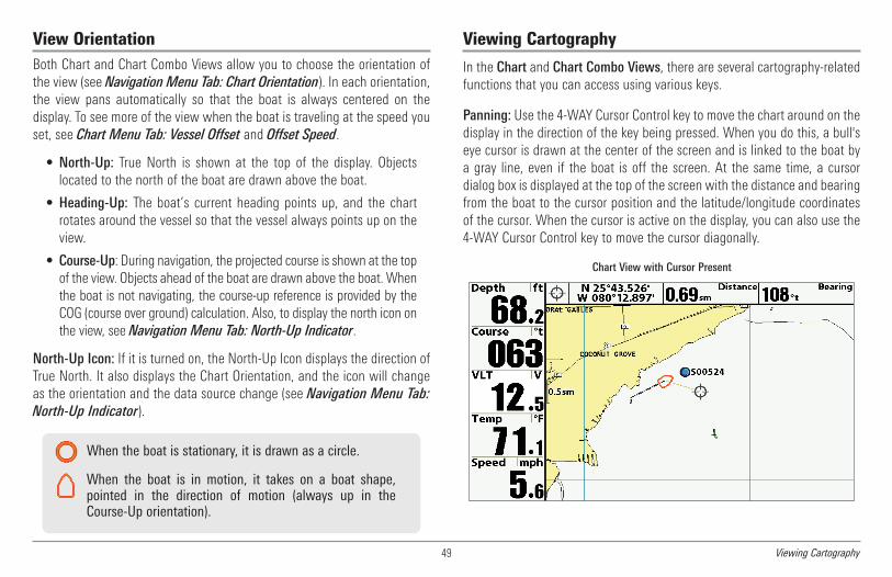
49 Viewing Cartography
View OrientationBoth Chart and Chart Combo Views allow you to choose the orientation ofthe view (see Navigation Menu Tab: Chart Orientation). In each orientation,the view pans automatically so that the boat is always centered on thedisplay. To see more of the view when the boat is traveling at the speed youset, see Chart Menu Tab: Vessel Offset and Offset Speed.
• North-Up: True North is shown at the top of the display. Objectslocated to the north of the boat are drawn above the boat.
• Heading-Up: The boat’s current heading points up, and the chartrotates around the vessel so that the vessel always points up on theview.
• Course-Up: During navigation, the projected course is shown at the topof the view. Objects ahead of the boat are drawn above the boat. Whenthe boat is not navigating, the course-up reference is provided by theCOG (course over ground) calculation. Also, to display the north icon onthe view, see Navigation Menu Tab: North-Up Indicator.
North-Up Icon: If it is turned on, the North-Up Icon displays the direction ofTrue North. It also displays the Chart Orientation, and the icon will changeas the orientation and the data source change (see Navigation Menu Tab:North-Up Indicator).
Viewing Cartography
In the Chart and Chart Combo Views, there are several cartography-relatedfunctions that you can access using various keys.
Panning: Use the 4-WAY Cursor Control key to move the chart around on thedisplay in the direction of the key being pressed. When you do this, a bull'seye cursor is drawn at the center of the screen and is linked to the boat bya gray line, even if the boat is off the screen. At the same time, a cursordialog box is displayed at the top of the screen with the distance and bearingfrom the boat to the cursor position and the latitude/longitude coordinatesof the cursor. When the cursor is active on the display, you can also use the4-WAY Cursor Control key to move the cursor diagonally.
Chart View with Cursor Present
When the boat is stationary, it is drawn as a circle.
When the boat is in motion, it takes on a boat shape,pointed in the direction of motion (always up in theCourse-Up orientation).

50Viewing Cartography
Zooming: Press the Plus (+) key to Zoom In and the Minus (-) key to ZoomOut to see the cartography at different magnification levels. The zoom levelis indicated on the left side of the display. If you zoom in beyond the availablechart data, the display will go into Overzoom mode whereby the lastavailable chart data is amplified to reflect the level selected. If you zoom inso far that no cartography is available, a lat/long grid will be drawn instead.Zooming is also influenced by the Auto Zoom and Auto Range settings. SeeChart Menu Tab: Auto Zoom and Auto Range for more information.
Decluttered Waypoints: When two or more waypoints overlap, or aredisplayed close together on a chart view, the screen will automaticallydeclutter — waypoint names will shorten and the waypoint icons willchange into small blue icons.
To view a Decluttered Waypoint at full size, use the 4-WAY Cursor Controlkey to move the cursor onto a decluttered waypoint icon. When the cursorsnaps onto the icon, the full-size waypoint name and icon will be displayed.You can also press the + ZOOM key until you can see the individualwaypoints on the screen.
Screen Snapshots and Recording Icons:When a waypoint is created whileScreen Snapshot and Recording is active, the waypoint will appear as asnapshot icon or recording icon in chart views. See Views: Snapshot andRecording View for more information.
Chart Info: Press the INFO key to get detailed information about the chart.If the cursor is active, you will see information about the chart objectslocated near the cursor.
If the cursor is not active, the Chart Infosubmenu will appear. Use the 4-WAY CursorControl key to select the Nearest Port, theNearest Tide Station, or the Nearest CurrentStation and see information about any ofthese objects.
NOTE: The built-in UniMap™ does not containany Port, Tide, or Current information. Thisinformation is only available from optional-purchase SD cards.
Nearest Port: The position and services information for the nearest port toyour present position will be displayed. Press the EXIT key to remove theinformation box and the cursor bull’s eye will be centered over the portposition. The cursor information boxes will indicate the distance and bearingto the port from your present position.
Nearest Tide Station: Tide information for the nearest tide station to yourpresent position will be displayed. This includes the position of the stationand the times of the high and low tides for today’s date. A tide graph is alsodisplayed showing the rise and fall of the tides for the 24 hour time periodencompassing the date. You can change the date to look at tide informationbefore or after the date displayed by pressing the LEFT or RIGHT Cursor keyrespectively. Press the EXIT key to remove the information box, and thecursor bull’s eye will be centered over the tide station position. The cursorinformation boxes indicate the distance and bearing to the tide station fromyour present position.

51 Introduction to Navigation
Nearest Current Station: Current information for the nearest current stationto your present position will be displayed. This includes the position of thestation and the current changes for today. Two graphs are also presentedthat show the time, direction, and flow speed of the current changes for the24 hour time period of today’s date. You can change the date to look atcurrent information before or after the date displayed by pressing the LEFTor RIGHT Cursor key respectively. Press the EXIT key to remove theinformation box, and the cursor bull’s eye will be centered over the currentstation position. The cursor information boxes will indicate the distance andbearing to the current station from your present position.
Introduction to Navigation
Your Fishing System allows you to mark waypoints and start navigation withthe control head keys or the Navigation X-Press™ Menu.
You can also use the Waypoint Management dialog box to create newwaypoints and routes from scratch. You can edit your navigation data andorganize it too. This section will get you started. See your Humminbird®Waypoint Management Guide for complete details.
Waypoints, Routes, and Tracks
Waypoints are stored positions that allow you to mark areas of interest ornavigation points. Your Fishing System can store up to 2,750 waypoints.
Routes link two or more waypoints together to create a path for navigation andare used in trip planning. You can link individual waypoints together by usingthe GOTO key. Your Fishing System can store up to 45 routes that can eachcontain up to 50 waypoints.
Waypoints, Routes and Tracks
Depth TTG: Estimate of Trip Time to Destination Waypoint1 6
Course: Direction the boat is travelingrelative to North Reference
Speed Over Ground: Speed of Boat2 7
Bearing: Direction to Destination WaypointRelative to North Reference
Waypoint3
8
Route 9
DTG: Distance to Go to Waypoint
Off-Course Alarm Limits
5
10
Map Scale 11
1
5
8
4
2
3
7
11 9
10
6
XTE: Cross Track Error. Distance of Boatfrom Route
4
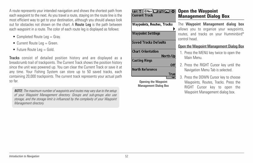
52Introduction to Navigation
A route represents your intended navigation and shows the shortest path fromeach waypoint to the next. As you travel a route, staying on the route line is themost efficient way to get to your destination, although you should always lookout for obstacles not shown on the chart. A Route Leg is the path betweeneach waypoint in a route. The color of each route leg is displayed as follows:
• Completed Route Leg = Gray.
• Current Route Leg = Green.
• Future Route Leg = Gold.
Tracks consist of detailed position history and are displayed as abreadcrumb trail of trackpoints. The Current Track shows the position historysince the unit was powered up. You can clear the Current Track or save it atany time. Your Fishing System can store up to 50 saved tracks, eachcontaining 20,000 trackpoints. The current track represents your actual pathso far.
Open the WaypointManagement Dialog Box
The Waypoint Management dialog boxallows you to organize your waypoints,routes, and tracks on your Humminbird®control head.
Open theWaypointManagement Dialog Box
1. Press the MENU key twice to open theMain Menu.
2. Press the RIGHT Cursor key until theNavigation Menu Tab is selected.
3. Press the DOWN Cursor key to chooseWaypoints, Routes, Tracks. Press theRIGHT Cursor key to open theWaypoint Management dialog box.
Opening the WaypointManagement Dialog Box
NOTE: The maximum number of waypoints and routes may vary due to the setupof your Waypoint Management directory. Groups and sub-groups also usestorage, and the storage limit is influenced by the complexity of your WaypointManagement directory.

53 Introduction to Navigation
What’s on the Waypoint Management Dialog Box
Use the Waypoint Management dialog box to manage your waypoints,routes, and tracks.
Use the 4-WAY Cursor Control key to select a waypoint, route,track, group, or menu option. To scroll through the list, pressthe UP or DOWN Cursor keys. To open a submenu, press theRIGHT Cursor key. To move to the higher level group, or thehigher level directory, press the LEFT Cursor key.
As you scroll through the Waypoint Management dialog box,press the EXIT key to select the Options menu quickly. Pressthe EXIT key twice to close the dialog box.
Sort By: Select Sort By, and press the RIGHT Cursor key repeatedlyto choose a sorting option for the waypoints, routes, tracks, andgroups (A - Z, Z - A, Newest, Oldest, Distance, Icon). To start a morespecific search, see Options.
Options: Provides a submenu so that you can set the default group,create new navigation items (groups, waypoints, routes), and selectand edit several items at once. Select Search By to search by Name,Distance, Date, Icon, or Icon Category. The Options menu will alsochange to show related menus such as Save or Paste.
Scroll and View: Press the UP or DOWN Cursor keys to browsethrough the full list of saved waypoints, routes, tracks, and groups.The selected item is highlighted in white.
Submenu: After an item is selected, press the RIGHT Cursor key toview the submenu.
Preview Window: As you scroll, the selected item’s information isdisplayed on the right side of the Waypoint Management dialogbox. Press the +/– ZOOM keys to view the position closer or fartheraway in the preview window.
Information: Displays the default group where all new waypoints,routes, and tracks will be saved. In this illustration, Home is thedefault group. This field also changes to display instructions.
F
E
D
C
B
A
J
I
H
K
G F
A B C D
E

54Introduction to Navigation
Directory: Shows the directory structure and the currently selectedgroup. The illustration shows group GP070 as the selected group.
Arrows: When arrows are displayed on a menu option, additionalinformation or submenus are available. If the arrow points to theright, press the RIGHT Cursor key. If the arrow points to the left,press the LEFT Cursor key to move up to the higher level groupdirectory.
Waypoint Icon: The blue circle icon is the default waypoint icon.Waypoint names are alphanumeric and begin with WP. You can alsochange the icon, waypoint name, add it to a route, and more. If thewaypoint is saved with a snapshot or recording file, see theSnapshot and Recording View on your control head to view thesnapshot or recording.
Track Icon: Track names are saved with a date and time stamp, andcertain track information can be edited (see Edit your Waypoints,Routes, Tracks, and Groups).
Route Icon: Route names are alphanumeric and begin with R. Tochange the Route name and its waypoints, see Edit yourWaypoints, Routes, Tracks, and Groups.
Save, Edit, or Delete a Waypoint
Save your Current Position as a Waypoint: On any view, press the MARKkey to save the current position of the boat as a waypoint.
Save the Cursor Position as a Waypoint: On the Chart or Chart ComboViews, use the 4-WAY Cursor Control key to move the cursor to the positionyou want to save as a waypoint. Then press the MARK key to save theposition as a waypoint.
Save a Position from the Sonar History: On any Sonar View, Side Imaging®View, or Down Imaging® View, use the 4-WAY Cursor Control key to move thecursor to a feature in the sonar history. Press the MARK key to create awaypoint at the location where that sonar reading was taken. The newwaypoint will also record the depth at that location.
Create a New Waypoint: To create a waypoint that is NOT your currentposition, open the Waypoint Management dialog box. Select Options > New> New Waypoint. Use the 4-WAY Cursor Control key to set the availablefields. See Edit your Waypoints, Routes, Tracks, and Groups for details.
Delete a Waypoint: Open the Waypoint Management dialog box. Select aWaypoint, and press the RIGHT Cursor key to open the Waypoint submenu.Select Delete, and press the RIGHT Cursor key. To remove the Waypoint fromthe group, choose Selected. To delete the waypoint from all groups, chooseAll Instances.
NOTE: When you save a waypoint by any of these methods, a numericalwaypoint name is automatically assigned. You can edit the waypointinformation later to give it a different name and select an icon to represent it(see Edit your Waypoints, Routes, Tracks, and Groups).
K
J
I
H
G

55 Introduction to Navigation
Navigate to a Waypoint or Position
Navigate to the Cursor Position: From the Chart or Chart Combo Views, usethe 4-WAY Cursor Control key to move the cursor to a position or waypointon the display. Press the GOTO key.
Navigate to a Selected Waypoint: Press the GOTO key. Press the DOWNCursor key to highlight a waypoint from the saved waypoints list, and pressthe RIGHT Cursor key to start navigation.
NOTE: By repeating the previous instructions, you can add more waypoints tocreate a longer multi-segment route.
Navigate to a Waypoint from the Waypoint Management Dialog Box:Open the Waypoint Management dialog box. Select a Waypoint, and pressthe RIGHT Cursor key to open the Waypoint submenu. Select Go To, andpress the RIGHT Cursor key.
Skip a Waypoint: From the Navigation X-Press™ Menu, select Skip NextWaypoint, and press the RIGHT Cursor key. If there is not another waypointto skip to, navigation will be cancelled.
Cancel Navigation: From the Navigation X-Press™ Menu, select CancelNavigation, and press the RIGHT Cursor key. Canceling navigation removesthe route and any waypoints created using the GOTO key, but it does notremove any saved routes from memory. You will be prompted to save thecurrent route when you cancel navigation.
Add a Waypoint Target or Trolling Grid
TheWaypoint Target shows a target consisting of concentric circles in variousdistance ranges centered on the waypoint you choose. The Trolling Gridshows various distance ranges in grid format from the waypoint you choose.The trolling grid can be used as a guide when trolling around a waypoint.
Add a Waypoint Target: Open theWaypoint Management dialog boxand select a Waypoint. Press theRIGHT Cursor key, and selectTarget. Press the RIGHT Cursor key.
Add a Trolling Grid: Open theWaypoint Management dialog boxand select a Waypoint. Press theRIGHT Cursor key, and select Grid.Press the RIGHT Cursor key. Thegrid can also be rotated to anyheading by adjusting the GridRotation setting on the NavigationMain Menu.
Remove Target or Trolling Grid:Press the MENU key once, andchoose Remove Target or RemoveGrid from the Navigation X-Press™Menu, and press the RIGHT Cursorkey.
Chart View with Target
Map Scale Waypoint Target1 2
1 2
Chart View with Grid
Map Scale Waypoint Trolling Grid1 2
1
2

56Introduction to Navigation
NOTE: Only one waypoint can have either a target or a grid applied to it at onetime. If you apply a target or a grid to a new waypoint, the original waypoint willlose its target or grid.
NOTE: The spacing of the rings on the waypoint target and the spacing of thegrid lines on the trolling grid are the same as the length of the scale bar on theleft edge of the display. Zooming in or out will decrease or increase the spacing,respectively.
Routes
Save the Current Route:While you are navigating, the current route can besaved. From the Navigation X-Press™ Menu, select Save Current Route, andpress the RIGHT Cursor key. Navigation will continue.
Create a New Route: Open the Waypoint Management dialog box. SelectOptions > New > New Route.
• New Route Dialog Box: Use the 4-WAY Cursor Control key to set theavailable fields (see Edit your Waypoints, Routes, Tracks, andGroups for details).
• Plan Route: Select Plan Route, and press the RIGHT Cursor key. TheNew Route dialog box closes so that you can select waypoints fromthe Waypoint Management dialog box. To add a selected waypointto the route, press the RIGHT Cursor key. Repeat as needed. SelectSave and press the RIGHT Cursor key.
Travel a Saved Route: Open the Waypoint Management dialog box. Selecta saved route, and press the RIGHT Cursor key. Select Travel, and press theRIGHT Cursor key. Select Forward to travel the route in order. Select Reverseto travel the route in reverse order.
Adding Waypoints to a Route
A confirmation displays each timeyou add a waypoint to the Route.
New Route Information: Showsthe Route’s name and next steps.
Save: Press the EXIT key to choose Save.Press the RIGHT Cursor key to confirm the save.
Selected Waypoint: Press the RIGHTCursor key to add it to the Route.
C
D
B
A
A
B
C
D

57 Introduction to Navigation
Edit the Waypoint Order in a Route: Open the Waypoint Managementdialog box. Select a Route, and press the RIGHT Cursor key to open theRoute submenu. Select Open, and then choose one of the following options:
• Select Reverse, and press the RIGHT Cursor key. This will quicklyreverse the order of the route. Press the EXIT key to select Save.Press the RIGHT Cursor key to confirm your changes.
OR
• Choose a Waypoint in a Route, and press the RIGHT Cursor key.Select Reorder, and press the RIGHT Cursor key. To move the waypointup or down in the route order, press the UP or DOWN Cursor keys.
Press the EXIT key to select Save. Press the RIGHT Cursor key toconfirm your changes.
Review Route Information: Open the Waypoint Management dialog box.Select a saved route, and press the RIGHT Cursor key. Select info, and pressthe RIGHT Cursor key. The Route Info dialog box displays the waypoints inthe route. The distance and bearing from each waypoint to the next, as wellas the distance and bearing from the current position to the first waypoint inthe route will be displayed.
Delete a Saved Route: Open the Waypoint Management dialog box. Select asaved route, and press the RIGHT Cursor key. Select Delete from the submenu,and press the RIGHT Cursor key. To remove the route from the group, chooseSelected. To delete the route from all groups, choose All Instances.
Tracks
Save the Current Track: From the Navigation X-Press™ Menu, select SaveCurrent Track, and press the RIGHT Cursor key. The track will remain on thedisplay but will change from black to gray. To remove the track completelyfrom the display, see Hide or Display a Saved Track and Stop Tracking.
NOTE:When you save a track, a name is automatically assigned. The track nameconsists of a date/time stamp, but can be re-named later (see Edit yourWaypoints, Routes, Tracks, and Groups).
Clear the Current Track: From the Navigation X-Press™ Menu, select ClearCurrent Track, and press the RIGHT Cursor key. The track will be removedfrom the display and permanently deleted.
Hide or Display a Saved Track: Open the Waypoint Management dialogbox. Select a saved track, and press the RIGHT Cursor key. Select Edit fromthe submenu. Use the 4-WAY Cursor Control key to set the track to visible orhidden (see Edit your Waypoints, Routes, Tracks, and Groups for details).
Changing the Waypoint Order in a Route (two options)
Select Reverse ORSelect a Waypoint>Reorder
Press the EXIT keyto select Save.

58Introduction to Navigation
Delete a Saved Track: Open the Waypoint Management dialog box. Selecta saved track, and press the RIGHT Cursor key. Select Delete from thesubmenu, and press the RIGHT Cursor key. To remove the track from thegroup, choose Selected. To remove the track from all groups, choose AllInstances.
Stop Tracking: Press the MENU key twice to open the Main Menu. Selectthe Navigation Menu Tab > Current Track > Stop Tracking. Stop Trackingclears the current track, and the unit will not save trackpoints. SeeNavigation Menu Tab: Current Track for more information.
Edit your Waypoints, Routes, Tracks, and Groups
Whether you are creating a new navigation item or editing it, you can usethe same steps to customize a waypoint, route, track, or group. The availablesettings will depend on the type of item you are editing.
NOTE: The Edit Waypoint dialog box is also available when you select a waypointfrom the Navigation X-Press™ Menu.
NOTE: See your Humminbird® Waypoint Management Guide for moreinformation about groups and the other great features of the WaypointManagement dialog box.
Visible on Chart View
Hidden on Chart View
Editing a Waypoint

59 Introduction to Navigation
Edit a Waypoint, Route, Track, or Group
1. Open the Waypoint Management dialog box.
2. Open the Submenu: Use the 4-WAY Cursor Control key to select awaypoint, route, track, or group. Press the RIGHT Cursor key to openthe submenu.
3. Select Edit, and press the RIGHT Cursor key.
4. Select a Field: Use the 4-Way Cursor Control key to move from fieldto field, and press the UP or DOWN Cursor keys to change thesettings.
Name: Press the RIGHT or LEFT Cursor keys to move from space tospace, and press the UP or DOWN Cursor keys to set the letter ornumber. All upper and lower case letters are available, as well asdigits 0-9 and some punctuation symbols.
Icon Category: Press the UP or DOWN Cursor keys to scrollthrough the available categories. Select All to view all availableicons. (All, Geometry, Alerts, Supplies, Navigation, Recreation,Fish, Environment)
Icon: Press the UP or DOWN Cursor keys to scroll through theavailable icons used to represent the waypoint in Chart View. Theavailable icons are determined by the category selected in IconCategory.
Visible: Press the UP or DOWN Cursor keys to set the selecteditem to visible or hidden in the Chart View.
Latitude/Longitude: Press the RIGHT or LEFT Cursor keys to movefrom space to space, and press the UP or DOWN Cursor keys to setthe letter or number.
NOTE: The available settings will depend on the type of item you are editing.

60Introduction to Navigation - MOB
Man Overboard (MOB) Navigation
As soon as you know that you have a man overboard (MOB), you shouldactivate MOB navigation to maximize the chances for a successful rescue.MOB navigation allows you to create an MOB waypoint to locate the pointat which your man went overboard and the relation of the boat to that point.
Activate MOB navigation: Press and hold the GOTO key for more than 1.5seconds to activate the Man Overboard (MOB) function.
When MOB is activated, a MOB waypoint is created at the boat's currentposition, regardless of whether the chart cursor is active or not. The MOBwaypoint has a large, distinctive icon. Once MOB is activated, any currentnavigation will be cancelled and the current route will be discarded withoutuser notification. MOB navigation will begin immediately, and the MOB Viewwill show the following:
• The view will switch to the Chart View, and the elapsed time sinceMOB was activated will be displayed.
• A line will be drawn from the boat's current position to the MOBwaypoint, and the MOB waypoint will be targeted.
• The latitude/longitude position of the MOB waypoint will bedisplayed in an additional information box.
Cancel MOB Navigation: From the Navigation X-Press™ Menu, selectCancel MOB, and press the RIGHT Cursor key. Canceling MOB navigationremoves the route and any waypoints created using the GOTO key but doesnot remove any saved routes from memory.
It is not possible to re-activate MOB or modify the current route withoutfirst canceling MOB navigation. The Off Course trigger is also disabled andthe Off Course Alarm circle is not drawn. Any press of the GOTO key, orselection of a GOTO menu option, will cause an error beep and a shortmessage will be displayed that will disappear after 2 seconds.
MOB Navigation
Position where man fell overboard Target surrounding MOB waypoint1 4Elapsed time since MOB was activated MOB waypoint2 5Boat icon3 6
1 2
3
4
5

61 The Menu System, Start-Up Options Menu
The Menu SystemThe Menu System is divided into easy-to-use menu modules as follows. Themain components of the menu system are as follows:
• Start-Up Options Menu: Press the MENU key during the power onsequence to view the Start-Up Options Menu. From the Start-UpOptions Menu, you can choose the following Fishfinder Modes:Normal, Simulator, and System Status.
• X-Press™ Menu: The X-Press™ Menu provides a shortcut to themost frequently-used settings, and the options on the X-Press™Menu correspond with the current view.
• Main Menu: The Main Menu is a standard set of menu settingswhich are organized under the following tabbed headings: Alarms,Sonar, Navigation, Chart, Setup, Views, and Accessories.
NOTE: The X-Press™ Menu(s) and the Main Menu options can also beexpanded or simplified by setting the User Mode to Advanced or Normal (seeMain Menu: User Mode).
Start-Up Options MenuPress the MENU key during the power on sequence to view the Start-UpOptions Menu, and select one of the modes described on the followingpages. Also, see Power On for more information.
NormalUse Normal for on-the-water operation with a transducer connected. If afunctioning transducer is connected, Normal operation will be selectedautomatically at power up, and your Fishing System can be used on the water.
To exit Normal operation, power off your Fishing System.
Start-Up Options Menu

62Start-Up Options Menu
SimulatorUse Simulator to learn how to use your Fishfinder before taking your boaton the water. The Simulator is a very powerful tool that provides a randomly-updated display which simulates on the water operation.
We recommend going through this manual while using the Simulator, sinceall of the menus function and affect the display in the same way as theywould in Normal operation. Any menu changes you make will be saved forlater use.
• A message will appear often on the display to indicate Simulatormode.
• To exit Simulator, power off your Fishing System.
NOTE: It is important to select Simulator manually from the Start-Up OptionsMenu as opposed to letting the Fishing System enter Simulator automatically (asit will if a transducer is not connected and you do nothing during power up).
System StatusUse System Status to view system connections and to conduct a unit self-test.
After you select System Status from the Start-Up Options Menu, press theVIEW key to display the following options:
• Self Test
• Accessory Test
• GPS Diagnostic View
To exit System Status, power off your Fishing System.
Self Test displays results from the internal diagnostic self test, including unitserial number, Printed Circuit Board (PCB) serial number, software revision,total hours of operation, and the input voltage.
Simulator
Self Test Screen

63 Start-Up Options Menu
Accessory Test lists the accessories connected to the system.
NOTE: The speed accessory will be detected only if the paddlewheel has movedsince your Fishing System was powered up.
GPS Diagnostic View shows a sky chart and numerical data from the GPSreceiver. The sky chart shows the location of each visible GPS satellite withits satellite number and a signal strength bar. A dark gray bar indicates thatthe satellite is being used to determine your current position. A light gray barindicates that the satellite is being monitored, but is not yet being used.
This view also reports the current position, local time and date, and othernumeric information. The current GPS Fix Type is reported as No Fix, 2D Fix,3D Fix, or Enhanced. An Enhanced fix has been augmented usinginformation from WAAS, EGNOS, or MSAS. A 3D or Enhanced Fix is requiredfor navigation. HDOP (the Horizontal Dilution of Precision) is a GPS systemparameter which depends on the current satellite configuration. HDOP isused to calculate the Estimated Position Error.
Accessory Test Screen
GPS Diagnostic View
Sky Chart Current Latitude and Longitude1 3Satellite Being Monitored 4Satellite Being Used2
1
3
2
4

64X-Press™ Menu, Main Menu
X-Press™ Menu
The X-Press™ Menu provides a shortcut toyour most frequently-used settings. Theoptions provided on the X-Press™ Menucorrespond with the current view. Forexample, if you are in a Sonar View andpress the MENU key once, the SonarX-Press™ Menu will display.
To use an X-Press™ Menu:
1. In any view, press the MENU key once.
2. Press the UP or DOWN Cursor keys to highlight an X-Press™ Menuoption, then use the RIGHT or LEFT Cursor keys to change the menusetting.
NOTE: The X-Press™ Menu will collapse temporarily and the screen willupdate if it is affected by your menu setting change, which allows you to seethe effects of your change immediately.
3. Reactivate the X-Press™Menu by pressing theUP or DOWNCursor keys.
Total Screen Update™ - When you change any menu settings that affectthe current view, the view will update immediately (i.e. you don’t have to exitthe menu to apply the change to the screen).
Main Menu
TheMain Menu provides the standard set ofmenu options, including the settings thatare changed less frequently. The Main Menuis organized under the following tabs to helpyou find a specific menu item quickly:Alarms, Sonar, Navigation, Chart, Setup,Views, and Accessories.
NOTE: Menu options can be expanded orsimplified by setting the User Mode toAdvanced or Normal. See Main Menu: UserMode for details.
To use the Main Menu:
1. In any view, press the MENU key twice.
2. Press the RIGHT or LEFT Cursor keys to highlight a menu tab.
3. Press the DOWN or UP Cursor keys to select a specific menu optionunder that tab.
4. Press the RIGHT or LEFT Cursor keys again to change a menu setting.
• A down arrow at the bottom of a menu means that you canscroll to additional menu options using the DOWN Cursor key.
• A right or left arrow on a menu option means that you can usethe RIGHT or LEFT Cursor keys to make changes or to see moreinformation.
• Press the EXIT key to move quickly to the top of the tab.
X-Press™ Menu
Menu options can be simplified or expanded by setting the User Mode toNormal or Advanced. SeeMain Menu: User Mode for details.
Main Menu System,Normal User Mode

65 Menu Quick Tips
Quick Tips for the Main Menu• From any menu option on a menu tab, press the EXIT key to jumpdirectly to the top of the tab.
• From the bottom of a menu tab, press the DOWN Cursor key tojump directly to the top of the tab.
• From the top of a menu tab, press the LEFT or RIGHT Cursor keys toscroll to the next tab. You can also jump to the beginning or end ofthe tab rotation by repeatedly pressing the RIGHT or LEFT Cursorkeys.
• If there is a down arrow at the bottom of a menu tab, press theDOWN Cursor key to scroll to additional menu options.
• If there is a right or left arrow on a menu option, press the RIGHTor LEFT Cursor keys to make setting changes or see moreinformation.
• If you press MENU or EXIT to leave the Main Menu and then returnto the Main Menu at a later time, the menu will open to the sametab as the last time the Main Menu was displayed.
Note for all Menu SettingsThe settings in all menus are adjusted in the same way. Simply use the 4-WAY Cursor Control key to highlight a menu option, and then change thesettings or activate the option (seeMain Menu or X-Press™ Menu).
Below is an example of how the menu options are described in this manual.Each description shows the menu option appearance, the available settings,and the specific control head settings required (i.e. advanced user mode,international only, view, navigation, or accessory).
Total Screen Update™ - When you change any menu settings that affectthe current view, the view will update immediately (i.e. you don’t have toexit the menu to apply the change to the screen).
Menu Option Name
Available MenuSettings
and Default
Setting Description
Menu Option as itappears on the screen
Setup User Modeand other control
head requirements

66Menu Quick Tips
User Mode (Normal or Advanced)Menu options can be simplified or expanded by setting your Fishing SystemUser Mode to Normal or Advanced.
Normal Mode is provided for users who want greater simplicity and fewermenu choices.
Advanced Mode is provided for users who want the highest level of controlover the Fishing System. Several menu settings are added to the Main Menuwhen the User Mode is changed to Advanced. Advanced mode is the defaultsetting when you first power on your Humminbird® Fishing System.
To change the User Mode setting:
1. Press the MENU key twice to access the Main Menu.
2. Press the RIGHT Cursor key until the Setup tab is selected.
3. Press the DOWN Cursor key to highlight User Mode on the Setupmain menu.
4. Press the LEFT or RIGHT Cursor keys to change the User Modesetting. (Normal, Advanced, Default = Advanced)
NOTE: Any changes made while in Advanced Mode will remain in effect afteryou switch back to Normal Mode.
For example, the Select Readouts menu option is available when the UserMode is set to Advanced. If you change the Select Readouts settings whileoperating in Advanced User mode, the Select Readouts you choose willcontinue to display on the screen even if you switch back to Normal UserMode.
999ci HD SISonar Tab, Normal Mode
999ci HD SISonar Tab, Advanced Mode

67 Sonar X-Press™ Menu
Sonar X-Press™ Menu
The Sonar X-Press™ Menu provides ashortcut to your most frequently-usedsettings. Press the MENU key once while inany of the Sonar Views to access the SonarX-Press™ Menu.
NOTE: Menu options can be expanded orsimplified by setting the User Mode toAdvanced or Normal. See Main Menu: UserMode for details.
NOTE: The selected transducer also influencesthe menu options. See Sonar Menu Tab:Connected Transducer for more information.
NOTE: Menu options are determined by yourHumminbird® model. See the following pagesfor full menu descriptions.
Cancel Navigation(only when Navigating)
Settings: Press the RIGHT Cursor key and followscreen instructions.
Cancel Navigation discards the current route and exits Navigation Mode.This menu option will only appear when you are currently navigating a route.This will not delete a previously-saved route.
Active Side(Combo Views only)
Settings: Left, Right, Default = Left
Active Side allows you to select a side of the screen in a Combo View. Afteryou choose an active side, you can apply menu settings and key commandsto the view you’ve selected. The Active Side menu option is only availablewhen a Combo View is on the screen (see Views: Combo Views).
• A green arrow on the Combo View points to the active side.
• When a menu is displayed in the active side, the non-active side ofthe screen will be grayed out.
Split Position(Combo Views only)
Settings: Left, 30, 40, 50, 60, 70, Right,Default = Various
Split Position sets the size of the left side of the Combo View. Each ComboView can be set individually. The Split Position menu option is only availablewhen a Combo View is on the screen (see Views: Combo Views).
Sonar X-Press™ Menu(shown with optional-purchasetransducer menu options)

68Sonar X-Press™ Menu
• The number setting indicates the percentage taken up by the leftside of the Combo View.
• Selecting Left sets the left side of the screen to its smallest setting.
SensitivitySettings: Low = 1, High = 20; Default = 10
Sensitivity controls how much detail is shown on the display and will adjustthe sensitivity of all sonar frequencies.
Decrease the sensitivity to eliminate theclutter from the display that is sometimespresent in murky or muddy water. IfSensitivity is adjusted too low, the displaymay not show many sonar returns thatcould be fish.
When operating in very clear water orgreater depths, increase the sensitivity tosee weaker returns that may be of interest.If the sensitivity is adjusted too high, thedisplay may become too cluttered.
NOTE: The Sensitivity setting is a global settingand will adjust the sensitivity of all sonarfrequencies.
.
Upper Range(Advanced: Sonar, Split Sonar and
Active Sonar Side Views only)
Settings: Various, see below.
Upper Range sets the shallowest depth range that will be displayed on theSonar, Split Sonar, and Active Sonar Side Views. Upper Range is often usedwith Lower Range.
NOTE: A minimum distance of 10 feet will be maintained between the Upper andLower Range regardless of the manual settings entered.
The available Upper Range settings are determined by your Humminbird®model as follows:
• 859ci HD/959ci HD: 0 to 1490 ft, 0 to 497 m (International Modelsonly); Default = 0
• 859ci HD DI/959ci HD DI: 0 to 1490 ft, 0 to 497 m (InternationalModels only); Default = 0
• 899ci HD SI/999ci HD SI: 0 to 1490 ft, 0 to 497 m (InternationalModels only); Default = 0
• 859ci HD XD/959ci HD XD: 0 to 3270 ft, 0 to 997 m (InternationalModels only); Default = 0
Sensitivity at Low
Sensitivity at Medium
Sensitivity at High
For example, if you are only interested in the area between 20 and 50 feetdeep, you should set the Upper Depth Range to 20 and the Lower DepthRange to 50. The Sonar View will then show the 30 foot area between 20and 50, and will not show the surface or the bottom (assuming the bottomis deeper than 50 feet), and will show greater detail for that area between20 and 50 feet.

69 Sonar X-Press™ Menu
Lower RangeSettings: Various, see below.
Lower Range sets the deepest depth range that will be displayed by the unit.
Auto: The Lower Range will be adjusted by the unit to follow the bottomautomatically. Auto is the default setting.
Manual: You can adjust the Lower Range to lock the unit on a particulardepth. will be displayed in the lower right corner of the screen toindicate the unit is in Manual mode. Adjust the Upper and Lower Rangetogether to view a specific depth range, especially when looking for fish orbottom structure.
NOTE: A minimum distance of 10 feet will be maintained between the Upper andLower Range regardless of the settings entered manually.
The available Lower Range settings are determined by your Humminbird®model as follows:
• 859ci HD/959ci HD: Auto to 1500 ft, Auto to 500 m (InternationalModels only); Default = Auto
• 859ci HD DI/959ci HD DI: Auto to 1500 ft, Auto to 500 m(International Models only); Default = Auto
• 899ci HD SI/999ci HD SI: Auto to 1500 ft, Auto to 500 m(International Models only); Default = Auto
• 859ci HD XD/959ci HD XD: Auto to 3280 ft, Auto to 1000 m(International Models only); Default = Auto
Chart SpeedSettings: 1 to 10, where 1 = Slow, 10 = Fastest;Default = 5
Chart Speed determines the speed at which the sonar information movesacross the display, and consequently the amount of detail shown.
A faster speed shows more information and is preferred by most anglers;however, the sonar information moves across the display quickly. A slowerspeed keeps the information on the display longer, but the bottom and fishdetails become compressed and may be difficult to interpret. Regardless ofthe Chart Speed setting, the RTSWindow™will update at the maximum ratepossible for the depth conditions.
Quad Layout(with optional-purchase QuadraBeam PLUS™
Transducer, Side Beam View only)
Settings: Default, Classic, Slanted, Default = Default
Quad Layout allows you to choose how sonar information is displayed in theSide Beam View. The Side Beam View displays sonar data from the left andright 455 kHz beams, as well as the 200 kHz down-looking beam. The sonardata can be displayed in any of the following layouts by changing the QuadLayout setting: Default, Classic, and Slanted. See Views: Side Beam View formore information.
For example, if you are fishing in 60 feet of water but are only interested inthe first 30 feet (surface to a depth of 30 feet) you should set the LowerDepth Range limit to 30. The display will show the 0 to 30 foot range,which allows you to see a more detailed view than you would see if thedisplay went all the way to the bottom.
M

70Sonar X-Press™ Menu, Side Imaging® X-Press™ Menu
NOTE: Quad Layout is only available when an optional-purchase QuadraBeamPLUS™ transducer is attached and the Side Beam View is active (see SonarMenu Tab: Connected Transducer).
Bottom Lock(Sonar Zoom View only)
Settings: Off, On; Default = Off
Bottom Lock changes the mode of the zoomed view in the Sonar ZoomView. Bottom Lock continuously graphs the bottom at a constant point onthe display regardless of changes in depth. This “flattens“ out the bottomcontour but is effective at showing fish on or near the bottom.
Bottom Range(Sonar Zoom View only, when Bottom Lock is On)
Settings: 10 to 60 feet, 2 to 10 fathoms, or 3 to 20meters [International Models only]; Default = 15feet
Bottom Range allows you to control how much of the water column,measured up from the bottom, is shown in the Sonar Zoom View. Choose asmall value to see low-lying bottom structure or details of the bottom return.Choose a larger value to see large structure in deeper water.
NOTE: It is possible to set the Bottom Range to be greater than the depth. In thiscase, you may see surface clutter in a wavy band that mirrors changes in thedepth.
Side Imaging® X-Press™ Menu(Side Imaging® Views only [899ci HD SI and999ci HD SI])
The Side Imaging® X-Press™ Menuprovides a shortcut to your most frequently-used settings. Press the MENU key oncewhile in any of the Side Imaging® Views toaccess the Side Imaging® X-Press™ Menu.
NOTE: Menu options can be expanded orsimplified by setting the User Mode toAdvanced or Normal. See Main Menu: UserMode for details.
Side Imaging® X-Press™ Menu

71 Side Imaging® X-Press™ Menu
Cancel Navigation(only when Navigating)
Settings: Press the RIGHT Cursor key and followscreen instructions.
Cancel Navigation discards the current route and exits Navigation Mode.This menu option will only appear when you are currently navigating a route.This will not delete a previously-saved route.
Active Side(Combo Views only)
Settings: Left, Right, Default = Left
Active Side allows you to select a side of the screen in a Combo View. Afteryou choose an active side, you can apply menu settings and key commandsto the view you’ve selected. The Active Side menu option is only availablewhen a Combo View is on the screen (see Views: Combo Views).
• A green arrow on the Combo View points to the active side.
• When a menu is displayed in the active side, the non-active side ofthe screen will be grayed out.
Split Position(Combo Views only)
Settings: Left, 30, 40, 50, 60, 70, Right;Default = Various
Split Position sets the size of the left side of the Combo View. Each ComboView can be set individually. The Split Position menu option is only availablewhen a Combo View is on the screen (see Views: Combo Views).
• The number setting indicates the percentage taken up by the leftside of the Combo View.
• Selecting Left sets the left side of the screen to its smallest setting.
SI SideSettings: Left, Both, Right, Default = Both
SI Side sets which transducer beam from the Side Imaging® beams will beshown on the display.
SI SensitivitySettings: 1 to 20, where Low = 1, High = 20,Default = 10
SI Sensitivity controls how much detail is shown on the display.
Increase the SI Sensitivity to reveal weaker returns that may be of interest,especially in very clear water or greater depths. A high SI Sensitivity settingshows more sonar returns from small baitfish and suspended debris in thewater; however if the SI Sensitivity is adjusted too high, the display maybecome too cluttered.
Decrease the SI Sensitivity to eliminate the clutter from the display that issometimes present in murky or muddy water. If SI Sensitivity is adjusted toolow, the display may not show many sonar returns that could be fish.

72Side Imaging® X-Press™ Menu
SI EnhanceSettings: Press the RIGHT Cursor key.
SI Enhance allows you to adjust your Side Imaging® View in four categories:Sensitivity, Contrast, Sharpness, and Contour Mode.
Whether you’re searching the Side Imaging® data for fish or certain bottomcontour, the most effective settings will vary with the situation. The displaywill update as you adjust each category. SI Enhance can also be used duringRecording Playback (see Snapshot and Recording View).
• Sensitivity - Controls how much detail is shown on the display.When operating in very clear water or greater depths, increasedsensitivity shows weaker returns that may be of interest. Decreasingthe sensitivity eliminates the clutter from the display thatis sometimes present in murky or muddy water. (1 to 20, whereLow = 1, High = 20, Default = 10)
NOTE: The Sensitivity can be adjusted from the SI Enhance dialog box or the SideImaging® X-Press™Menu. The Sensitivity setting is provided here so that you caneasily adjust the Side Imaging® data with the other settings. See Side Imaging®X-Press™ Menu: SI Sensitivity for more information.
• Contrast: Accents the light and dark parts of the Side Imaging® datato provide greater definition. (1 to 20, Default = 10)
• Sharpness: Filters the view and sharpens the edges of the SideImaging® data. (Low (L), Medium (M), High (H), Default = Off)
• Contour Mode: Controls how the water column is displayed in theSide Imaging® Views. In the normal display with the Contour Modeoff, the water column is displayed on the view. The location of atarget on the display is based on the slant range to the target.
When Contour Mode is turned on, the bottom is graphed at aconstant point on the display, regardless of changes in depth. TheSide Imaging® beams are divided by a vertical line. The water columnis removed from the view, which allows the display to show targetsat their linear horizontal distance. The location of a target may beeasier to interpret when the water column is removed. (Off, On;Default = Off)
NOTE: If both SI Range Lines and Contour Mode are turned on, the SI RangeLines will remain on the display, but the individual range numbers are notavailable (see Sonar Menu Tab: SI Range Lines).
SI RangeSettings: Auto, 6 to 360 feet, or 2 to 120 meters[International Models only], Default = 150 feet, 50meters
SI Range sets the deepest range that will displayed in the Side Imaging®views. The range must be set manually.
SI Enhance Submenu
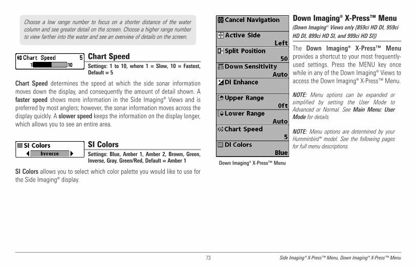
73 Side Imaging® X-Press™ Menu, Down Imaging® X-Press™ Menu
Chart SpeedSettings: 1 to 10, where 1 = Slow, 10 = Fastest,Default = 5
Chart Speed determines the speed at which the side sonar informationmoves down the display, and consequently the amount of detail shown. Afaster speed shows more information in the Side Imaging® Views and ispreferred by most anglers; however, the sonar information moves across thedisplay quickly. A slower speed keeps the information on the display longer,which allows you to see an entire area.
SI ColorsSettings: Blue, Amber 1, Amber 2, Brown, Green,Inverse, Gray, Green/Red, Default = Amber 1
SI Colors allows you to select which color palette you would like to use forthe Side Imaging® display.
Down Imaging® X-Press™ Menu(Down Imaging® Views only [859ci HD DI, 959ci
HD DI, 899ci HD SI, and 999ci HD SI])
The Down Imaging® X-Press™ Menuprovides a shortcut to your most frequently-used settings. Press the MENU key oncewhile in any of the Down Imaging® Views toaccess the Down Imaging® X-Press™ Menu.
NOTE: Menu options can be expanded orsimplified by setting the User Mode toAdvanced or Normal. See Main Menu: UserMode for details.
NOTE: Menu options are determined by yourHumminbird® model. See the following pagesfor full menu descriptions.
Down Imaging® X-Press™ Menu
Choose a low range number to focus on a shorter distance of the watercolumn and see greater detail on the screen. Choose a higher range numberto view farther into the water and see an overview of details on the screen.

74Down Imaging® X-Press™ Menu
Cancel Navigation(only when Navigating)
Settings: Press the RIGHT Cursor key and followscreen instructions.
Cancel Navigation discards the current route and exits Navigation Mode.This menu option will only appear when you are currently navigating a route.This will not delete a previously-saved route.
Active Side(Combo Views only)
Settings: Left, Right, Default = Left
Active Side allows you to select a side of the screen in a Combo View. Afteryou choose an active side, you can apply menu settings and key commandsto the view you’ve selected. The Active Side menu option is only availablewhen a Combo View is on the screen (see Views: Combo Views).
• A green arrow on the Combo View points to the active side.
• When a menu is displayed in the active side, the non-active side ofthe screen will be grayed out.
Split Position(Combo Views only)Settings: Left, 30, 40, 50, 60, 70, Right,Default = Various
Split Position sets the size of the left side of the Combo View. Each ComboView can be set individually. The Split Position menu option is only availablewhen a Combo View is on the screen (see Views: Combo Views).
• The number setting indicates the percentage taken up by the leftside of the Combo View.
• Selecting Left sets the left side of the screen to its smallest setting.
Down SensitivitySettings: 1 to 20, where Low = 1, High = 20,Default = 10
Down Sensitivity controls how the sonar returns are displayed on the DownImaging® Views.
Increase the Down Sensitivity to reveal weaker returns that may be ofinterest, especially in very clear water or greater depths. A high DownImaging® Sensitivity setting shows more sonar returns from small baitfishand suspended debris in the water; however if the Down Imaging®Sensitivity is adjusted too high, the display may become too cluttered.
Decrease the Down Sensitivity to eliminate the clutter from the display thatis sometimes present in murky or muddy water. If Down Imaging® Sensitivityis adjusted too low, the display may not show many sonar returns that couldbe fish.
DI EnhanceSettings: Press the RIGHT Cursor key.
DI Enhance allows you to adjust your Down Imaging® View in the followingcategories: Sensitivity, Contrast, and Sharpness.
Whether you’re searching the Down Imaging® data for fish or certain bottomcontour, the most effective settings will vary with the situation. The displaywill update as you adjust each category. DI Enhance can also be used duringRecording Playback (see Views: Snapshot and Recording View).

75 Down Imaging® X-Press™ Menu
• Sensitivity: Controls how much detail is shown on the display. Whenoperating in very clear water or greater depths, increased sensitivityshows weaker returns that may be of interest. Decreasing thesensitivity eliminates the clutter from the display that is sometimespresent in murky or muddy water. (1 to 20, where Low = 1, High = 20;Default = 10)
NOTE: The Sensitivity can be adjusted from the DI Enhance dialog box or the DownImaging® X-Press™ Menu. The Sensitivity setting is provided here so that you caneasily adjust the Down Imaging® data with the other settings. See Down Imaging®X-Press™ Menu: Down Sensitivity for more information.
• Contrast: Accents the light and dark parts of the Down Imaging®data to provide greater definition. (1 to 20, Default = 10)
• Sharpness: Filters the view and sharpens the edges of the DownImaging® data. (Low (L), Medium (M), High (H), Default = Off)
Upper Range(Advanced, Down Imaging® Views only)
Settings: 0 to 1490 feet or 0 to 497 meters[International models only], Default = 0
Upper Range sets the shallowest depth range that will be displayed on theDown Imaging® Views. Upper Range is often used with Lower Range.
NOTE: A minimum distance of 10 feet will be maintained between the Upper andLower Range regardless of the manual settings entered.
Lower RangeSettings: Auto to 1500 feet, Auto to 500 meters[International Models only]; Default = Auto
Lower Range sets the deepest depth range that will be displayed by the unit.
Auto: The Lower Range will be adjusted by the unit to follow the bottomautomatically. Auto is the default setting.
Manual: You can adjust the Lower Range to lock the unit on a particulardepth. will be displayed in the lower right corner of the screen toindicate the unit is in Manual mode. Adjust the Upper and Lower Rangetogether to view a specific depth range, especially when looking for fish orbottom structure.
For example, if you are fishing in 60 feet of water but are only interested inthe first 30 feet (surface to a depth of 30 feet) you should set the LowerDepth Range limit to 30. The display will show the 0 to 30 foot range,which allows you to see a more detailed view than you would see if thedisplay went all the way to the bottom.
M
For example, if you are only interested in the area between 20 and 50 feetdeep, you should set the Upper Depth Range to 20 and the Lower DepthRange to 50. The Down Imaging® View will then show the 30 foot areabetween 20 and 50, and will not show the surface or the bottom (assumingthe bottom is deeper than 50 feet), and will show greater detail for thatarea between 20 and 50 feet.
DI Enhance Submenu

76Down Imaging® X-Press™ Menu, Navigation X-Press™ Menu
NOTE: A minimum distance of 10 feet will be maintained between the Upper andLower Range regardless of the settings entered manually.
Chart SpeedSettings: 1 to 10, where 1 = Slow, 10 = Fastest,Default = 5
Chart Speed determines the speed at which the sonar information movesacross the display, and consequently the amount of detail shown.
A faster speed shows more information and is preferred by most anglers;however, the sonar information moves across the display quickly. A slowerspeed keeps the information on the display longer, but the bottom and fishdetails become compressed and may be difficult to interpret.
DI ColorsSettings: Blue, Amber 1, Amber 2, Brown, Green,Inverse, Gray, Green/Red, Default = Amber 1
DI Colors allows you to select which color palette you would like to use forthe Down Imaging® display.
Navigation X-Press™ Menu
The Navigation X-Press™ Menu provides ashortcut to your most frequently-usedsettings. Press the MENU key once while inthe Bird's Eye View, Chart View, or ChartCombo Views to access the NavigationX-Press™ Menu.
NOTE: Menu options will vary depending onsystem settings, such as whether you arecurrently navigating.
NOTE: Menu options can be expanded orsimplified by setting the User Mode toAdvanced or Normal. See Main Menu: UserMode for details.
NOTE: To see the Navigation X-Press™ Menu ina Combo View, change the Active Side settingto the side you want to adjust.
See Introduction to Navigationand the Humminbird® WaypointManagement Guide for moreinformation.
Navigation X-Press™ Menu

77 Navigation X-Press™ Menu
Cancel Navigation(only when Navigating)
Settings: Press the RIGHT Cursor key and followscreen instructions.
Cancel Navigation discards the current route and exits Navigation Mode.This menu option will only appear when you are currently navigating a route.This will not delete a previously-saved route.
Cancel MOB Navigation(only when MOB Navigation is activated)
Settings: Press the RIGHT Cursor key and followscreen instructions.
Cancel MOB Navigation removes the Man Overboard (MOB) waypoint andexits Man Overboard mode. This menu option will only appear when you arecurrently navigating in Man Overboard mode.
Skip Next Waypoint(only when Navigating)
Settings: Press the RIGHT Cursor key and followscreen instructions.
Skip Next Waypoint removes the next waypoint from the current route. Thismenu option will only appear when you are currently navigating a route.
Active Side(Combo Views only)
Settings: Left, Right, Default = Left
Active Side allows you to select a side of the screen in a Combo View. Afteryou choose an active side, you can apply menu settings and key commandsto the view you’ve selected. The Active Side menu option is only availablewhen a Combo View is on the screen (see Views: Combo Views).
• A green arrow on the Combo View points to the active side.
• When a menu is displayed in the active side, the non-active side ofthe screen will be grayed out.
Split Position(Combo Views only)
Settings: Left, 30, 40, 50, 60, 70, Right,Default = Various
Split Position sets the size of the left side of the Combo View. Each ComboView can be set individually. The Split Position menu option is only availablewhen a Combo View is on the screen (see Views: Combo Views).
• The number setting indicates the percentage taken up by the left sideof the Combo View.
• Selecting Left sets the left side of the screen to its smallest setting.

78Navigation X-Press™ Menu
Waypoint [Name](Only with an active cursor on a waypoint)
Settings: Edit, Delete, Target, Grid
Waypoint [Name] allows you to view the Waypoints submenu for thewaypoint under your cursor. You can move the cursor onto an existingwaypoint and press the MENU key once, or use Cursor to Waypoint toselect a waypoint from the saved waypoints list.
NOTE: See Introduction to Navigation and the Humminbird® WaypointManagement Guide for more information.
The Waypoint Submenu includes the following menu options:
Edit opens the Edit Waypoint dialog box so that you can edit theselected waypoint. See Introduction to Navigation and theHumminbird® Waypoint Management Guide for more information.
Delete allows you to delete the waypoint.
Target applies a target to the waypoint.
Grid applies a trolling grid to the waypoint.
Cursor to Waypoint(Chart or Chart Combo View only)
Settings: Press the RIGHT Cursor key and followscreen instructions.
Cursor to Waypoint allows you to quickly move the cursor to any savedwaypoint so that you can locate it or edit it. This X-Press™ Menu option onlyappears if you have saved waypoints.
Chart DeclutterSettings: Press the RIGHT Cursor key to activate.
Chart Declutter removes all chart layers except for land outlines, waypoints,routes, and tracks. The chart will stay decluttered for 10 seconds, and thenit will refresh to its previous display settings. To refresh the view faster than10 seconds, press the +/– Zoom keys.
NOTE: See Chart Menu Tab: Chart Detail Level for more information.
Save Current TrackSettings: Press the RIGHT Cursor key and followscreen instructions.
Save Current Track allows you to save the current track on the display. Afterthe current track is saved, a new current track is started. Save Current Trackappears on the Navigation X-Press™ Menu after navigation is stopped.
Clear Current TrackSettings: Press the RIGHT Cursor key and followscreen instructions.
Clear Current Track allows you to clear the current track on the display andstart a new track at the present position.
NOTE: To save the depth information with the current track, it is important tosave the track and also edit the name before powering off the control head.

79 Navigation X-Press™ Menu
Save Current Route(only when Navigating)
Settings: Press the RIGHT Cursor key and followscreen instructions.
Save Current Route allows you to save the current route being displayed.This menu option will only appear when you are currently navigating a route.
Reset XTE(only when Navigating)
Settings: Press the RIGHT Cursor key to activate.
Reset XTE is available during navigation. When it is selected, the cross trackerror (XTE) will be recalculated from the boat’s current position to the nextwaypoint in the route.
For example, when you’ve deviated from a route to navigate around anisland, select Reset XTE to update the unit’s course calculations from thecurrent boat position instead of from the previous waypoint in the route.
Remove Target(only if a Target is Active)
Settings: Press the RIGHT Cursor key to activate.
Remove Target removes the waypoint target from the display. This menuoption will only appear when a target has already been applied to awaypoint.
NOTE: See Introduction to Navigation: Add a Waypoint Target or Trolling Gridfor more information.
Remove Grid(only if a Grid is Active)
Settings: Press the RIGHT Cursor key to activate.
Remove Grid removes the waypoint grid from the display. This menu optionwill only appear when a grid has already been applied to a waypoint.
NOTE: See Introduction to Navigation: Add a Waypoint Target or Trolling Gridfor more information.
Waypoint [Name](Most recently-created waypoint)
Settings: Edit, Delete, Go To, Target, Grid
Waypoint [Name] allows you to view the waypoints submenu for the mostrecently created waypoint. You must have pressed the MARK key at least oncesince you last powered up the Fishfinder for this menu option to appear.
NOTE: See Introduction to Navigation and the Humminbird® WaypointManagement Guide for more information.
The Waypoint Submenu includes the following menu options:
Edit opens the Edit Waypoint dialog box so that you can edit theselected waypoint. See Introduction to Navigation and theHumminbird® Waypoint Management Guide for more information.
Delete allows you to delete the waypoint.
Go To starts navigation to the waypoint.
Target applies a target to the waypoint.
Grid applies a trolling grid to the waypoint.
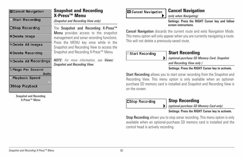
80Snapshot and Recording X-Press™ Menu
Snapshot and RecordingX-Press™ Menu(Snapshot and Recording View only)
The Snapshot and Recording X-Press™Menu provides access to the snapshotmanagement and sonar recording functions.Press the MENU key once while in theSnapshot and Recording View to access theSnapshot and Recording X-Press™ Menu.
NOTE: For more information, see Views:Snapshot and Recording View.
Cancel Navigation(only when Navigating)
Settings: Press the RIGHT Cursor key and followscreen instructions.
Cancel Navigation discards the current route and exits Navigation Mode.This menu option will only appear when you are currently navigating a route.This will not delete a previously-saved route.
Start Recording(optional-purchase SD Memory Card, Snapshot
and Recording View only )
Settings: Press the RIGHT Cursor key to activate.
Start Recording allows you to start sonar recording from the Snapshot andRecording View. This menu option is only available when an optional-purchase SD memory card is installed and Snapshot and Recording View ison the screen.
Stop Recording(optional-purchase SD Memory Card only)
Settings: Press the RIGHT Cursor key to activate.
Stop Recording allows you to stop sonar recording. This menu option is onlyavailable when an optional-purchase SD memory card is installed and thecontrol head is actively recording.
Snapshot and RecordingX-Press™ Menu

81 Snapshot and Recording X-Press™ Menu
Delete Image(optional-purchase SD Memory Card, Snapshotand Recording View only)
Settings: Press the RIGHT Cursor key and followscreen instructions.
Delete Image allows you to delete a single screen capture image. This menuoption is only available when an optional-purchase SD card is installed,Snapshot and Recording View is on the screen, and you have selected animage thumbnail.
Delete All Images(optional-purchase SD Memory Card, Snapshotand Recording View only)
Settings: Press the RIGHT Cursor key and followscreen instructions.
Delete All Images allows you to delete all the images at once. This menuoption is only available when an optional-purchase SD memory card isinstalled and Snapshot and Recording View is on the screen.
Delete Recording(optional-purchase SD Memory Card, Snapshotand Recording View only)
Settings: Press the RIGHT Cursor key and followscreen instructions.
Delete Recording allows you to delete a single sonar recording. This menuoption is only available when an optional-purchase SD memory card isinstalled, Snapshot and Recording View is on the screen, and you haveselected a recording file.
Delete All Recordings(optional-purchase SD Memory Card, Snapshotand Recording View only)
Settings: Press the RIGHT Cursor key and followscreen instructions.
Delete All Recordings allows you to delete all the recordings at once. Thismenu option is only available when an optional-purchase SD memory card isinstalled and Snapshot and Recording View is on the screen.
Pings Per Second(optional-purchase SD Memory Card, Snapshotand Recording View only)
Settings: 1 to 10, Auto, Default = Auto
Pings Per Second allows you to specify the ping rate for an active sonarrecording.
NOTE: Pings Per Second is available when an optional-purchase SD memory cardis installed, Snapshot and Recording View is on the screen, and the control headis actively recording (not playing back).
Auto is the default setting for Pings Per Second and automatically adjuststhe ping rate for best recording quality. If there is limited memory on your SDmemory card, you can slow the ping rate by setting the Pings Per Secondmanually, but the recording will capture less sonar detail. For maximumperformance, keep the Pings Per Second setting on Auto.

82Snapshot and Recording X-Press™ Menu
Playback Speed(optional-purchase SD Memory Card, Snapshot
and Recording View only)
Settings: Record, Rewind1, Rewind2, Slow PlayReverse, Pause, Slow Play, Normal Play, FastForward1, Fast Forward2, Stop
Playback Speed allows you to specify the playback speed for a sonarrecording from the Snapshot and Recording View. This menu option is onlyavailable when an optional-purchase SD card is installed and RecordingPlayback is active.
NOTE: You can also change playback speed in the Snapshot and Recording Viewusing the LEFT and RIGHT Cursor keys, although you cannot skip to the beginningor end of a recording using these keys.
NOTE: Sonar chart speed is increased during Fast Forward and reversed duringRewind. This may result in a reduced quality sonar image, since at higher speeds,not every sonar return can be processed.
Stop Playback(optional-purchase SD Memory Card only)
Settings: Press the RIGHT Cursor key to activate.
Stop Playback allows you to stop playback of a sonar recording from anyview. This menu option is only available when an optional-purchase SDmemory card is installed and Recording Playback is active.
NOTE: During playback, the amount of time/memory left to play is indicated bythe status bar. For more information, see Views: Snapshot and RecordingView.
Playback Speed Icons:
Record Slow Play
Rewind, Reverse Normal Play
Rewind2 Fast Forward
Slow Play Reverse Fast Forward2
Pause Stop

83 Alarms Menu Tab
Alarms Menu Tab
From any view, press the MENU key twice toaccess the Main Menu. The Alarms tab willbe the default selection.
NOTE: When an alarm is triggered, you cansilence it by pressing any key. The alarm will besilenced, and will not be triggered again until anew instance of the alarm condition isdetected.
Depth AlarmSettings: Off, 1 to 100 feet, or 0.5 to 30 meters[International Models only]; Default = Off
Depth Alarm sounds when the depth becomes equal to or less than themenu setting.
Fish ID AlarmSettings: Off, All, Large/Medium, Large;Default = Off
Fish ID Alarm sounds when the Fishfinder detects fish that correspond tothe alarm setting. Fish ID Alarm will only sound if Fish ID+™ is on.
Off
All
Large/Medium
Large
For example, if you've set the Fish ID Alarm to sound for Large fish only, theFish ID alarm will sound when a large-sized fish is detected.
Alarms Menu
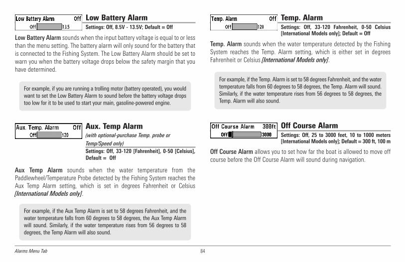
84Alarms Menu Tab
Low Battery AlarmSettings: Off, 8.5V - 13.5V; Default = Off
Low Battery Alarm sounds when the input battery voltage is equal to or lessthan the menu setting. The battery alarm will only sound for the battery thatis connected to the Fishing System. The Low Battery Alarm should be set towarn you when the battery voltage drops below the safety margin that youhave determined.
Aux. Temp Alarm(with optional-purchase Temp. probe or
Temp/Speed only)Settings: Off, 33-120 [Fahrenheit], 0-50 [Celsius],Default = Off
Aux Temp Alarm sounds when the water temperature from thePaddlewheel/Temperature Probe detected by the Fishing System reaches theAux Temp Alarm setting, which is set in degrees Fahrenheit or Celsius[International Models only].
Temp. AlarmSettings: Off, 33-120 Fahrenheit, 0-50 Celsius[International Models only]; Default = Off
Temp. Alarm sounds when the water temperature detected by the FishingSystem reaches the Temp. Alarm setting, which is either set in degreesFahrenheit or Celsius [International Models only].
Off Course AlarmSettings: Off, 25 to 3000 feet, 10 to 1000 meters[International Models only]; Default = 300 ft, 100 m
Off Course Alarm allows you to set how far the boat is allowed to move offcourse before the Off Course Alarm will sound during navigation.
For example, if the Temp. Alarm is set to 58 degrees Fahrenheit, and the watertemperature falls from 60 degrees to 58 degrees, the Temp. Alarm will sound.Similarly, if the water temperature rises from 56 degrees to 58 degrees, theTemp. Alarm will also sound.
For example, if the Aux Temp Alarm is set to 58 degrees Fahrenheit, and thewater temperature falls from 60 degrees to 58 degrees, the Aux Temp Alarmwill sound. Similarly, if the water temperature rises from 56 degrees to 58degrees, the Temp Alarm will also sound.
For example, if you are running a trolling motor (battery operated), you wouldwant to set the Low Battery Alarm to sound before the battery voltage dropstoo low for it to be used to start your main, gasoline-powered engine.

85 Alarms Menu Tab
Arrival AlarmSettings: Off, 25 to 3000 feet, 10 to 1000 meters[International Models only]; Default = 150 ft, 50 m
Arrival Alarm sounds when the boat has either exceeded the distance to thedestination waypoint, or has entered the Arrival Alarm Circle, based on themenu setting when navigating. Arrival Alarm allows you to set how close theboat must be to the destination waypoint before the Arrival Alarm willsound.
Drift AlarmSettings: Off, 25 to 3000 feet, 10 to 1000 meters[International Models only]; Default = Off
Drift Alarm allows you to set the size of a perimeter around the boat’sanchored position. If the anchored boat drifts outside of that perimeter, theDrift Alarm will sound.
Alarm ToneSettings: High, Medium, Low; Default = Medium
Alarm Tone selects the pitch of the alarm sound. A brief tone will beproduced as you adjust the Alarm Tone so that you can select the tone thatyou can hear best.
Drift Alarm Circle
Off Course Alarm
Arrival Alarm Circle Off Course Limits1 2
1
2

86Alarms Menu Tab
Timer SetupSettings: Press the RIGHT Cursor key to open thedialog box.
Timer Setup allows you to open a dialog box to create settings for theTimer. You can also start the countdown from this dialog box. When theTimer is started, the clock counts down from the amount of time set in thedialog box.
• Time: Use the 4-WAY Cursor Control key to set the hours, minutes,and seconds.
• Save and Start: To start the Timer immediately, select Save andStart, and press the RIGHT Cursor key.
• Save and Close: To save your settings and start the Timer at a latertime, select Save and Close, and press the RIGHT Cursor key. Also,see Start Timer.
• Digital Readout: To display the Timer on-screen as it counts down,see Views: To Change the Digital Readouts.
Start TimerSettings: Press the RIGHT Cursor key to start theTimer.
Start Timer allows you to start the Timer using the saved countdownsettings in the Timer Setup dialog box. To create the Timer settings, seeTimer Setup.
Stop Timer(with the Timer running)
Settings: Press the RIGHT Cursor key to stop theTimer.
Stop Timer allows you to stop the Timer while it is counting down.
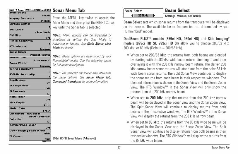
87 Sonar Menu Tab
Sonar Menu Tab
Press the MENU key twice to access theMain Menu and then press the RIGHT Cursorkey until the Sonar tab is selected.
NOTE: Menu options can be expanded orsimplified by setting the User Mode toAdvanced or Normal. See Main Menu: UserMode for details.
NOTE: Menu options are determined by yourHumminbird® model. See the following pagesfor full menu descriptions.
NOTE: The selected transducer also influencesthe menu options. See Sonar Menu Tab:Connected Transducer for more information.
999ci HD SI Sonar Menu (Advanced)
Beam SelectSettings: Various, see below.
Beam Select sets which sonar returns from the transducer will be displayedon the screen. The available beam frequencies are determined by yourHumminbird® model.
DualBeam PLUS™ models (859ci HD, 959ci HD) and Side Imaging®models (899ci HD SI, 999ci HD SI) allow you to choose 200/83 kHz,200 kHz, or 83 kHz (Default = 200/83 kHz).
• When set to 200/83 kHz, the returns from both beams are blendedby starting with the 83 kHz wide beam return, dimming it, and thenoverlaying it with the 200 kHz narrow beam return. The darker 200kHz narrow beam sonar returns will stand out from the paler 83 kHzwide beam sonar returns. The Split Sonar View continues to displaythe sonar returns from each beam in their respective windows. Theblended information is shown in the Sonar View and the Sonar ZoomView. The RTS Window™ in the Sonar View will only show thereturns from the 200 kHz narrow beam.
• When set to 200 kHz, only the returns from the 200 kHz narrowbeam will be displayed in the Sonar View and the Sonar Zoom View.The Split Sonar View will continue to display returns from bothbeams in their respective windows. The RTS Window™ in the SonarView will display the returns from the 200 kHz narrow beam.
• When set to 83 kHz, the returns from the 83 kHz wide beam will bedisplayed in the Sonar View and the Sonar Zoom View. The SplitSonar View will continue to display returns from both beams in theirrespective windows. The RTS Window™ will display the returns fromthe 83 kHz wide beam.
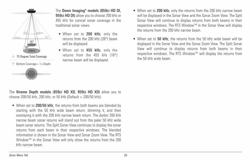
88Sonar Menu Tab
The Down Imaging® models (859ci HD DI,959ci HD DI) allow you to choose 200 kHz or455 kHz for conical sonar coverage in thetraditional sonar views.
• When set to 200 kHz, only thereturns from the 200 kHz (28°) beamwill be displayed.
• When set to 455 kHz, only thereturns from the 455 kHz (16°)narrow beam will be displayed.
The Xtreme Depth models (859ci HD XD, 959ci HD XD) allow you tochoose 200/50 kHz, 200 kHz, or 50 kHz (Default = 200/50 kHz).
• When set to 200/50 kHz, the returns from both beams are blended bystarting with the 50 kHz wide beam return, dimming it, and thenoverlaying it with the 200 kHz narrow beam return. The darker 200 kHznarrow beam sonar returns will stand out from the paler 50 kHz widebeam sonar returns. The Split Sonar View continues to display the sonarreturns from each beam in their respective windows. The blendedinformation is shown in the Sonar View and Sonar Zoom View. The RTSWindow™ in the Sonar View will only show the returns from the 200kHz narrow beam.
• When set to 200 kHz, only the returns from the 200 kHz narrow beamwill be displayed in the Sonar View and the Sonar Zoom View. The SplitSonar View will continue to display returns from both beams in theirrespective windows. The RTS Window™ in the Sonar View will displaythe returns from the 200 kHz narrow beam.
• When set to 50 kHz, the returns from the 50 kHz wide beam will bedisplayed in the Sonar View and the Sonar Zoom View. The Split SonarView will continue to display returns from both beams in theirrespective windows. The RTS Window™ will display the returns fromthe 50 kHz wide beam.75 Degree Total Coverage
16°
28°455kHz
200kHz
75°455kHz
45° 800kHz

89 Sonar Menu Tab
Imaging Frequency(859ci HD DI, 959ci HD DI, 899ci HD SI and 999ci
HD SI only)
Settings: Various, see below.
Imaging Frequency allows you to select which frequency to apply to theDown Imaging® and Side Imaging® beams. For the best overall image qualityand depth, select 455 kHz. For the sharpest image (but limited depthcapability), select 800 kHz.
• 859ci HD DI: 800 kHz, 455 kHz;Default = 455 kHz
• 959ci HD DI: 800 kHz, 455 kHz;Default = 455 kHz
• 899ci HD SI: 455 kHz;Default = 455 kHz
• 999ci HD SI: 800 kHz, 455 kHz;Default = 455 kHz
Surface ClutterSettings: Low = 1 to High = 10; Default = 5
Surface Clutter adjusts the filter that removes surface clutter noise causedby algae and aeration. The lower the setting, the less surface clutter will bedisplayed.
SwitchFire®Settings: Clear Mode, Max Mode; Default = ClearMode
SwitchFire® controls how the sonar returns are displayed in the Sonar Views.
Choose Max Mode to see only raw sonar returns on the display. When MaxMode is selected, you will see the maximum sonar information available withinthe transducer beam, so more fish arches and better jig tracking are shown.
Choose Clear Mode to see less clutter and more fish size accuracy on thedisplay. When Clear Mode is selected, the clutter is filtered, and sonarreturns are interpreted to provide more details about the objects within thetransducer beam, regardless of their location. In other words, a large arch onthe display means a large fish has been detected.
Surface Clutter
75 Degree Total Coverage
16°
28°455kHz
200kHz
75°455kHz
45° 800kHz
Down Imaging® Beams

90Sonar Menu Tab
Fish ID+™Settings: Off, On; Default = Off
Fish ID+™ uses advanced signal processing to interpret sonar returns andwill display a Fish Symbol when very selective requirements are met. Whena fish is detected, a fish icon and its depth are displayed above the returnthat has been classified as being a fish. Three different fish size iconsrepresent the intensity of the sonar return and provide an indicator ofrelative fish size.
In DualBeam PLUS™ models (859ci HD, 959ci HD, 899ci HD SI, and999ci HD SI), targets detected in the 200 kHz narrow beam are representedas orange fish symbols, and targets detected in the 83 kHz wide beam arerepresented as blue fish symbols.
In Down Imaging® models (859ci HD DI and 959ci HD DI), targets detectedin the 455 kHz conical beam are represented as blue fish symbols, and targetsdetected in the 200 kHz conical beam are represented as orange fish symbols.
In the Xtreme Depth models (859ci HD XD and 959ci HD XD), targetsdetected in the 200 kHz narrow beam are represented as orange fishsymbols and targets detected in the 50 kHz wide beam are represented asblue fish symbols.
When Fish ID+™ is turned off, the Fishfinder shows only the raw sonarreturns on the display. These returns will often result in “arches“ forming on
the display, indicating potential targets. Due to the transducer beam angle,the distance to a fish decreases as the fish moves into the beam, and thenincreases as it moves out again, creating a Fish Arch when this distancechange is shown on the display. Boat speed, chart speed, and the positionof the fish within the sonar beam greatly affect the shape of the arch.
Fish ID SensitivitySettings: Low = 1, High = 10; Default = 5
Fish ID Sensitivity adjusts the threshold of the Fish ID+™ detectionalgorithms. Selecting a higher setting allows weaker returns to be displayedas fish. This is useful for identifying smaller fish species or baitfish. Selectinga lower setting displays fewer fish from weak sonar returns. This is helpfulwhen seeking larger species of fish.
Fish ID Sensitivity is used in conjunction with Fish ID+™. Fish ID+™ must beOn for Fish ID Sensitivity to affect the ability of the Fishfinder to identifysonar returns as fish.
Transducer Cone and Fish Arches
Narrow beamOrange Fish Symbols
Wide beamBlue Fish Symbols

91 Sonar Menu Tab
Real Time Sonar (RTS™) WindowSettings: Wide, Narrow, Off; Default = Narrow
RTS Window™ sets the RTS Window™ to Wide or Narrow, or turns it off inthe Sonar Views. The RTS Window™ always updates at the fastest ratepossible and only displays returns that are within the transducer beam. SeeWhat’s on the Sonar Display for more information.
NOTE: The Wide RTS Window™ does not usegrayscale.
Sonar ColorsSettings: Gray, Green, Inverse, Original Palette,Palette 1, Palette 2, Palette 3; Default = Original
Sonar Colors allows you to select which color palette you would like to usefor the display. The palette you choose will be applied to the Sonar Views.
• Gray: Light Gray (weak) to Black (strong)
• Green: Dark Green (weak) to Light Green (strong)
• Inverse: Black (weak) to White (strong)
• Original Palette: Cyan (weak) to Red (strong)
• Palette 1: Navy Blue (weak), Purple (medium), Yellow (strong)
• Palette 2: Navy Blue (weak), Green (medium), Yellow (strong)
• Palette 3: Navy Blue (weak) to Red (strong)
Bottom ViewSettings: Structure ID, WhiteLine; Default =Structure ID
Bottom View selects the method used to represent bottom and structure onthe display.
• Structure ID™ represents weak returns in blue and strong returns inred. If the Sonar Colors palette is changed, the Structure ID™ willdisplay the strongest return as specified by the palette.
• WhiteLine™ highlights the strongest sonar returns in white,resulting in a distinctive outline. This has the benefit of clearlydefining the bottom on the display.
SeeWhat’s on the Sonar Display: Sonar Colors and Bottom View for moreinformation.
RTS Window™ (Wide)
RTS Window™ (Narrow)
RTS Window™ (Off)

92Sonar Menu Tab
Zoom Width(Sonar Zoom View only)
Settings: Narrow, Medium, Wide; Default = Wide
Zoom Width adjusts the width of the zoomed view on the Sonar Zoom View.See Views: Sonar Zoom View for more information.
50 kHz Sensitivity(Advanced, XD Sonar only [859ci HD XD, 959ci HD XD])
Settings: -10 to +10; Default = 0
50 kHz Sensitivity changes the sensitivity of the 50 kHz beam. Increasingthe 50 kHz Sensitivity will display additional weak returns, and decreasingthe 50 kHz Sensitivity will display fewer weak returns.
NOTE: 50 kHz Sensitivity is particularly useful for adjusting the sensitivity of the50 kHz sonar returns in the 200/50 kHz Split Sonar View. The 50 kHz sensitivitycan be adjusted without affecting the sensitivity of the 200 kHz returns shown inthe 200 kHz sonar window.
83 kHz Sensitivity(Advanced, DualBeam PLUS™ Sonar only
[859ci HD, 959ci HD, 899ci HD SI, 999ci HD SI])
Settings: -10 to +10, Default = 0
83 kHz Sensitivity changes the sensitivity of the 83 kHz beam. Increasingthe 83 kHz Sensitivity will display additional weak returns, and decreasingthe 83 kHz Sensitivity will display fewer weak returns.
NOTE: 83 kHz Sensitivity is particularly useful for adjusting the sensitivity of the83 kHz sonar returns in the 200/83kHz Split Sonar View. The 83 kHz sensitivitycan be adjusted without affecting the sensitivity of the 200 kHz returns shown inthe 200 kHz sonar window.
455 kHz Sensitivity(Advanced, Down Imaging® Views only
[859ci HD DI and 959ci HD DI])
Settings: -10 to +10, Default = 0
455 kHz Sensitivity adjusts the sensitivity of the 455 kHz beam. Increase thesensitivity to display additional weak returns and decrease the sensitivity todisplay fewer weak returns.
455 kHz Sensitivity(Advanced, with optional-purchase QuadraBeam
PLUS™ transducer)
Settings: -10 to +10, Default = 0
455 kHz Sensitivity adjusts the sensitivity of the 455 kHz beam. Increase thesensitivity to display additional weak returns and decrease the sensitivity todisplay fewer weak returns.
The 455 kHz Sensitivity menu option is available when a QuadraBeamPLUS™ transducer is attached to the Fishing System, User Mode is set toAdvanced (see Setup Menu Tab: User Mode), and Connected Transducer isset to QuadraBeam (see Sonar Menu Tab: Connected Transducer).
NOTE: Visit our Web site at humminbird.com to order this accessory online orcontact our Customer Resource Center at 1-800-633-1468.
NOTE: 455 kHz Sensitivity is particularly useful for adjusting the sensitivity ofthe 455 kHz sonar returns in the Side Beam View. The 455 kHz sensitivity canbe adjusted without affecting the sensitivity of the 200 kHz returns shown inthe 200 kHz sonar window.
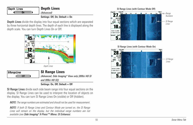
93 Sonar Menu Tab
Depth Lines(Advanced)
Settings: Off, On; Default = On
Depth Lines divide the display into four equal sections which are separatedby three horizontal depth lines. The depth of each line is displayed along thedepth scale. You can turn Depth Lines On or Off.
SI Range Lines(Advanced, Side Imaging® View only [899ci HD SI
and 999ci HD SI])
Settings: On, Off; Default = Off
SI Range Lines divide each side beam range into four equal sections on thedisplay. SI Range Lines can be used to interpret the location of objects onthe display. You can turn SI Range Lines On (visible) or Off (hidden).
NOTE: The range numbers are estimated and should not be used for measurement.
NOTE: If both SI Range Lines and Contour Mode are turned on, the SI RangeLines will remain on the display, but the individual range numbers are notavailable (see Side Imaging® X-Press™ Menu: SI Enhance).
SI RangeLines
SI Range Lines (with Contour Mode On)
SI RangeLines
RangeNumbers
SI Range Lines (with Contour Mode Off)
Depth Lines

94Sonar Menu Tab
SI Readouts(Advanced, Side Imaging® View only [899ci HD SI
and 999ci HD SI])
Settings: On, Off; Default = On
SI Readouts allows you to display or hide the digital readout boxes in theSide Imaging® View.
When SI Readouts is set to Off, Temperature and Depth will continue to bedisplayed on the screen.
NOTE: See Setup Menu Tab: Select Readouts for more information.
Noise Filter(Advanced)
Settings: Off, Low, Medium, High 1, High 2, High 3;Default = Low
Noise Filter adjusts the sonar Noise Filter to limit interference on the displayfrom sources such as your boat engine, turbulence, or other sonar devices.
The Off setting removes all filtering. Low, Medium, and High 1, High 2, High3 settings add progressive filtering of the sonar returns. High 1, High 2, andHigh 3 are useful when there is excessive trolling motor noise, but in somedeep water situations, the High settings may actually hinder your unit’sability to find the bottom.
Max Depth(Advanced)
Settings: Various, see below.
Max Depth controls the maximum depth of operation. When Max Depth isset to Auto, the Fishing System will acquire bottom readings as needed(within the capacity of the unit). When Max Depth is set to match yourfishing maximum depth, your Fishing System will not attempt to acquiresonar data below that depth, so more detail will be shown on the screen.
NOTE: If the bottom is deeper than the Max Depth setting, the digital depthreadout will flash, indicating that the Fishfinder cannot locate the bottom.
• 859ci HD/959ci HD: Auto to 1500 ft, Auto to 500 m (InternationalModels only); Default = Auto
• 859ci HD DI/959ci HD DI: Auto to 1500 ft, Auto to 500 m(International Models only); Default = Auto
• 899ci HD SI/999ci HD SI: Auto to 1500 ft, Auto to 500 m(International Models only); Default = Auto
• 859ci HD XD/959ci HD XD: Auto to 3280 ft, Auto to 1000 m(International Models only); Default = Auto
Max Depth controls the down beam reading. The SI Range (Side Imaging®Range) controls the side beams and down beam reading at the same time.If SI Range is set to a deeper range than the Max Depth setting, your899ci HD SI Combo or 999ci HD SI Combo will default to the SI Rangesetting. For example, if you set the Max Depth to 50 feet and then set theSI Range to 150 feet, your unit will acquire bottom readings from 150 feet(see Side Imaging® X-Press™Menu: SI Range).

95 Sonar Menu Tab
Water Type(Advanced)
Settings: Fresh, Salt (shallow), Salt (deep);Default = Fresh
Water Type configures your unit for operation in fresh or salt water. In saltwater, you can also choose the shallow or deep setting. The Water Typemenu option is available when User Mode is set to Advanced (see MainMenu: User Mode).
Digital Depth Source(Advanced, Down Imaging® models withoptional-purchase transducers only [859ci HDDI and 959ci HD DI)
Settings: Auto, 2D Element; Default = Auto
Digital Depth Source specifies the beams that will be used to provide thedepth for the digital depth readouts (see Views and SetupMenu Tab: SelectReadouts for more information). It is important to set this menu option basedon the transducer that is connected to the control head, as follows:
• If a Down Imaging® transducer is connected to the control head,select Auto. Depending on the depth, Auto will automatically choosethe 2D conical beams or the Down Imaging® beams to display depthin the digital readout window. Auto is the default setting.
• If an accessory transducer is connected to the control head, select2D Element. For example, if you connect an ice transducer to yourDown Imaging® unit, change the digital depth source to 2D Elementin order to display depth in the digital readout window. The 2DElement setting should not be used with a Down Imaging®transducer.
NOTE: Visit our Web site at humminbird.com to determine which accessorytransducers are compatible with your Humminbird® Fishing System, or Contactour Customer Resource Center.
NOTE: When Digital Depth Source is set to 2D Element, the DI setting will beremoved from the DI Pings menu. When DI Pings is set to DI, the 2D Elementsetting will be removed from the Digital Depth Source menu. See DI Pings formore information.
NOTE:Make sure that the Water Type is set accurately, especially in salt water,as this affects the accuracy of deep water depth readings. In salt water, whatwould be considered a large fish might be 2 to 10 times bigger than a large fishin fresh water (depending on the type of fish you are seeking). The salt watersetting allows for a greater range in fish size adjustment to account for thisdifference.

96Sonar Menu Tab
Connected TransducerSettings: Hi-Def Sidescan, Compact Sidescan,Sidescan, DI 200/455, DI 200/83, DI 200/50, QuadBeam, Dual Beam, Dual 50/200, Universal Sonar 2;Default = Various, see below
Connected Transducer allows you to choose which connected transduceryou want to use. When you choose a transducer, the corresponding featureswill be automatically added to your Fishing System.
NOTE: This feature may appear as either Connected Transducer or TransducerSelect, depending on your model.
• 859ci HD and 959ci HD: Dual Beam is the default selection. TheQuadraBeam PLUS™, Dual 50/200 kHz and Universal Sonar 2transducers require a separate purchase. The 859ci HD/959ci HD doesnot support High-Definition Sidescan, Compact Sidescan, or Sidescantransducers.
• 859ci HD DI and 959ci HD DI: Down Imaging® is the default selection.The DI 200/50 kHz, Dual 50/200 kHz, Dual 83/200 kHz, and UniversalSonar 2 transducers require a separate purchase. The 859ci HDDI/959ci HD DI does not support High-Definition Sidescan, CompactSidescan, or Sidescan transducers.
• 899ci HD SI: Compact Sidescan is the default selection. Hi-DefSidescan, Sidescan, Down Imaging®, QuadraBeam PLUS™, Dual Beam,Dual 50/200, and Universal 2 require a separate purchase.
• 999ci HD SI: Hi-Def Sidescan is the default selection. The CompactSidescan, Sidescan, Down Imaging®, QuadraBeam PLUS™, Dual Beam,Dual 50/200, and Universal Sonar 2 require a separate purchase.
• 859ci HD XD and 959ci HD XD: Your Fishing System will default toDual 200/50. Your Fishing System also supports the optional-purchaseDualBeam PLUS™ transducer (XNT 9 20) and optional-purchaseUniversal Sonar 2.
NOTE: To purchase transducers, visit our Web site at humminbird.com or callour Customer Resource Center at 1-800-633-1468.
DI Pings(Advanced, Down Imaging® View andChart/Down Combo View only)
Settings: 2D + DI, DI; Default = 2D + DI
DI Pings allows you to select which beams will be used to display returns inthe Down Imaging® view.
Select 2D + DI to display returns from both the 2D sonar beams and theDown Imaging® beams.
Select DI to display returns from the Down Imaging® beams only. SelectingDI provides faster screen updates.
NOTE: When DI Pings is set to DI, the 2D Element setting will be removed fromthe Digital Depth Source menu. When the Digital Depth Source is set to 2DElement, the DI setting will be removed from the DI Pings menu. See DigitalDepth Source for more information.

97 Sonar Menu Tab
NOTE: See How Sonar Works: Down Imaging® Sonar for more information.
Color BarSettings: Off, On, Default = On
Color Bar allows you to display or suppress the display of the color barshown in the full screen Sonar View.
Temperature Graph(Sonar View only, with Temperature input)
Settings: Off, On, Default = On
Temperature Graph allows you to display or suppress a water temperaturegraph over the main Sonar View to show temperature changes correlated torecent sonar history.
DI Colors(859ci HD DI, 959ci HD DI, 899ci HD SI, and 999ci
HD SI only)
Settings: Blue, Amber 1, Amber 2, Brown, Green,Inverse, Gray, Green/Red; Default = Amber 1
DI Colors allows you to select which color palette you would like to use forthe Down Imaging® display.
Down Imaging® Beam Width(Advanced, 899ci HD SI and 999ci HD SI only)
Settings: Narrow, Medium, Wide; Default = Wide
Down Imaging® Beam Width controls the width of the beam (side to side)for the Down Imaging® View and sets the amount of information shown onthe display.
To see only the data directly under your boat, select Narrow. Medium revealsmore information, while Wide displays the maximum information availablefrom the Down Imaging® beam width.
75 Degree Total Coverage
16°75°
28°455kHz
200kHz
455kHz
45° 800kHz
DownImaging®beams
2D Sonarbeams
DI Pings

98Navigation Menu Tab
Navigation Menu Tab
Press the MENU key twice to access theMain Menu, then press the RIGHT Cursorkey until the Navigation tab is selected.
NOTE: Menu options will vary depending onsystem settings, such as whether you arecurrently navigating.
NOTE: Menu options can be expanded orsimplified by setting the User Mode toAdvanced or Normal. See Main Menu: UserMode for details.
NOTE: Menu options are determined by yourHumminbird® model. See the following pagesfor full menu descriptions.
899ci HD SI, 999ci HD SINavigation Menu Tab, Advanced
Current TrackSettings: Save, Clear, Appearance, StopTracking
Current Track allows you to view the Current Track submenu. SeeIntroduction to Navigation: Tracks for more information.
The Current Track Submenu contains the following menu options:
Save allows you to save the current track.
Clear allows you to delete the current track.
Appearance allows you to change the style and color of the currenttrack. (Breadcrumb Trail, Dashed Line, Solid Line or Wide Line, and ifa line, the color of the line, or Color By Depth).
• If you choose Color By Depth, you cannot choose one color torepresent the track. A color range will represent the differentdepths on the track instead, from light green (shallowest) toblack (deepest). You can change the depth range associatedwith black by using the Track Color Range menu setting (seeNavigation Menu Tab: Track Color Range).
• If you choose Hidden, the unit continues to save trackpoints,but the track will not be displayed on the view.
Stop Tracking clears the current track and the unit will not savetrackpoints. To resume saving the track, select Current Track > StartTracking.
NOTE: To save the depth information with the Current Track, it is important tosave the track and also edit the name before powering off the control head.

99 Navigation Menu Tab
Waypoints, Routes, Tracks(Waypoint Management Dialog Box)
Settings: Press the RIGHT Cursor key to open thedialog box.
Waypoints, Routes, Tracks allows you to open the Waypoint Managementdialog box. Use the Waypoint Management dialog box to create newwaypoints and routes and organize your navigation data. You can also editwaypoint, route, and track information. Your navigation data can be savedinto groups, sorted, copied, and exported to HumminbirdPC™.
Waypoint SettingsSettings: Press the RIGHT Cursor key to open thedialog box.
Waypoint Settings allows you to open the Waypoint Settings dialog box.Use the Waypoint Settings dialog box to set the waypoint icon category andthe waypoint icon for all new waypoints. See Introduction to Navigation:Edit your Waypoints, Routes, Tracks, and Groups and the Humminbird®Waypoint Management Guide for details.
The Waypoint Settings dialog box includes the following options:
Icon Category allows you to select a waypoint icon category (All,Geometry, Alerts, Supplies, Navigation, Recreation, Fish,Environment). The Default Waypoint Icon also changes to match theselected category.
Default Waypoint Icon allows you select an icon for all newwaypoints. To see the most icon choices, set the Icon Category to All.
New Waypoint Icon:
Select Default, and the system will automatically apply yoursettings to new waypoints.
If you choose Select, each time you mark a waypoint (bypressing the MARK key), you will be prompted to change thewaypoint icon and category. To accept the current settings,press the MARK key again.
Saved Tracks DefaultsSettings: Press the RIGHT Cursor key to open thedialog box.
Saved Tracks Defaults allows you to open the Default Track dialog box. Usethe dialog box to set the default track appearance for all newly-saved tracks.
The Saved Tracks dialog box includes the following options:
Visibility allows you to set new tracks to visible or hidden.
Style allows you to set the appearance and color of new tracks(Breadcrumb Trail, Dashed Line, Solid Line or Wide Line, and if a line,the color of the line, or Color By Depth).
If you choose Color By Depth, you cannot choose one color torepresent the track. A color range will represent the different depthson the track instead, from light green (shallowest) to black (deepest).You can change the depth range associated with black by using theTrack Color Range menu setting (see Navigation Menu Tab: TrackColor Range).
See Introduction to Navigation and the Humminbird® WaypointManagement Guide for more information.
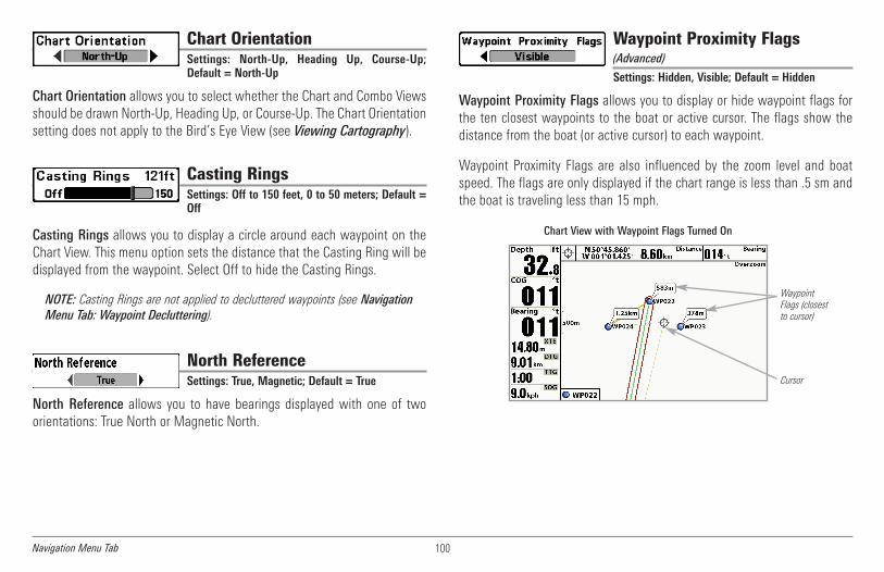
100
Chart OrientationSettings: North-Up, Heading Up, Course-Up;Default = North-Up
Chart Orientation allows you to select whether the Chart and Combo Viewsshould be drawn North-Up, Heading Up, or Course-Up. The Chart Orientationsetting does not apply to the Bird’s Eye View (see Viewing Cartography).
Casting RingsSettings: Off to 150 feet, 0 to 50 meters; Default =Off
Casting Rings allows you to display a circle around each waypoint on theChart View. This menu option sets the distance that the Casting Ring will bedisplayed from the waypoint. Select Off to hide the Casting Rings.
NOTE: Casting Rings are not applied to decluttered waypoints (see NavigationMenu Tab: Waypoint Decluttering).
North ReferenceSettings: True, Magnetic; Default = True
North Reference allows you to have bearings displayed with one of twoorientations: True North or Magnetic North.
Waypoint Proximity Flags(Advanced)
Settings: Hidden, Visible; Default = Hidden
Waypoint Proximity Flags allows you to display or hide waypoint flags forthe ten closest waypoints to the boat or active cursor. The flags show thedistance from the boat (or active cursor) to each waypoint.
Waypoint Proximity Flags are also influenced by the zoom level and boatspeed. The flags are only displayed if the chart range is less than .5 sm andthe boat is traveling less than 15 mph.
Chart View with Waypoint Flags Turned On
WaypointFlags (closestto cursor)
Cursor
Navigation Menu Tab

101
Waypoint Decluttering(Advanced)
Settings: Off, On; Default = On
Waypoint Decluttering allows you to set the declutter feature On or Off.When two or more waypoints overlap, or are displayed close together on achart view, the screen will automatically declutter—waypoint names willshorten and the waypoint icons will change into small blue icons. Select Offto display waypoints at regular size.
Trolling Grid RotationSettings: 0° to 89°, Default = 0°
Trolling Grid Rotation allows you to set the orientation of the trolling grid indegrees, where a setting of 0° displays a standard North, South, East, Westalignment. See Introduction to Navigation: Add a Waypoint Target orTrolling Grid for information.
NOTE: This feature may appear as either Trolling Grid Rotation or Grid Rotation,depending on your model.
Trackpoint IntervalSettings: 1 second, 5 seconds, 10 seconds,15 seconds, 30 seconds, or 60 seconds;Default = 1 second
Trackpoint Interval allows you to select the time period betweentrackpoints. The current track can only contain up to 20,000 trackpoints, solonger time periods cause the track to extend back further in time, but willbe less detailed.
Trackpoint Interval works in conjunction with Track Min Distance. Bothconditions must be met before a trackpoint is added to the current track.During slow travel or drift, setting both Trackpoint Interval and Track MinDistance to small values will allow you to increase the track resolution.
Track Min Distance(Advanced)Settings: 1 to 300 feet, or 1 to 100 meters[International Units only]; Default = 16 ft, 5 m
Track Min Distance allows you to set a minimum distance of travel before atrackpoint is added to the track.
Track Min Distance works in conjunction with Trackpoint Interval. Bothconditions must be met before a trackpoint is added to the current track.During slow travel or drift, setting both Trackpoint Interval and Track MinDistance to small values will allow you to increase the track resolution.
Track Color RangeSettings: 50 to 3000* feet or 20 to 1000 meters[International Units only], Default = 50 ft, 20 m
Track Color Range allows you to set the depth range that will be displayedas black, the deepest depth, when Color By Depth is selected as the style forthe current track (see Navigation Menu Tab: Current Track).
*NOTE: Only an optional-purchase transducer with a 50 kHz frequency will allowyou to track to 3000 feet.
Navigation Menu Tab

102
Map Datum(Advanced)
Settings: Various, Default = WGS 84
Map Datum allows you to change the map coordinate system used by theFishing System to match those of a paper map.
North-Up IndicatorSettings: On, Off; Default = Off
North-Up allows you to display the North-Up icon on the screen to indicatethe direction of True North. The icon also displays the Chart Orientation, andit will change as the orientation and the data source change. To set theChart Orientation, see Navigation Menu Tab. Also, see Views: ViewOrientation.
Course Projection LineSettings: Hidden, Standard, Single Vector,COG/SOG; Default = Standard
Course Projection Line displays an arrow or line, extending from the bow ofthe boat, that projects your current course and shows where the boat will goif you continue on your present course.
You can choose the style of the Course Projection Line as follows:
• Standard = arrow
• Single Vector = line
• COG/SOG = line with tick marks at set intervals from the boat. Thetick marks are based on the speed calculation.
3D View OutlineSettings: Hidden, Visible, Default = Visible
3D View Outline allows you to display or hide an outline on the Chart sideof either Chart or Bird's Eye Combo Views that shows what you're viewingon the Bird's Eye side of the view.
Continuous Navigation ModeSettings: Off, On, Default = Off
Continuous Navigation Mode allows you to continue to navigate and fisharound a particular waypoint, even if you pass over it multiple times.
SI Navigation(Side Imaging® models only [899ci HD SI and
999ci HD SI])
Settings: Off, On, Default = On
SI Navigation controls how the boat icon is displayed in Side Imaging®Views. If SI Navigation is turned on, the boat icon indicates the direction theboat needs to turn to reach the next waypoint during navigation. The boaticon color will also change to orange.
If SI Navigation is turned Off, the boat icon will not change during navigationalthough you can still mark waypoints and start navigation from a SideImaging® View. See Side Imaging® View and Introduction to Navigation formore information.
Navigation Menu Tab

103
Chart Menu Tab
Press the MENU key twice to access theMain Menu and then press the RIGHT Cursorkey until the Chart tab is selected.
NOTE: Menu options can be expanded orsimplified by setting the User Mode toAdvanced or Normal. See Main Menu: UserMode for details.
Chart Menu (Advanced, shown with optional-purchaseNavionics® and LakeMaster® menu options)
Lat/Lon GridSettings: Hidden, Visible, Default = Hidden
Lat/Lon Grid allows you to display or hide a grid showing latitude andlongitude lines.
Navaids on Bird’s Eye ViewSettings: Hidden, Visible, Default = Visible
Navaids on Bird's Eye View allows you to display or hide additionalnavigational aids in Bird’s Eye View, such as lights and buoys.
NOTE: You will see more navigational aids with an optional-purchase SD card.
Chart SelectSettings: Auto, Contour XD, Left Chart Card,Right Chart Card; Default = Auto
Chart Select allows you to choose which chart to use if you have built-incharts or a map card. If you select Auto, your unit will select a chartautomatically. Select Right to use the SD card installed in the right card slot,and select Left to use the SD card installed in the left card slot (see SDMemory Card Slots: Add Maps to Your Fishing System).
NOTE: The SD Memory Cards require a separate purchase. For more information,visit our Web site at humminbird.com or contact our Customer Resource Centerat 1-800-633-1468.
NOTE: When a map from an optionalpurchase SD card is installed, the ChartMenu Tab will change to display menuoptions that correspond with the activechart. To manually select a chart card, seeChart Select. Also, see Add Maps to theFishing System for more information.
Chart Menu Tab
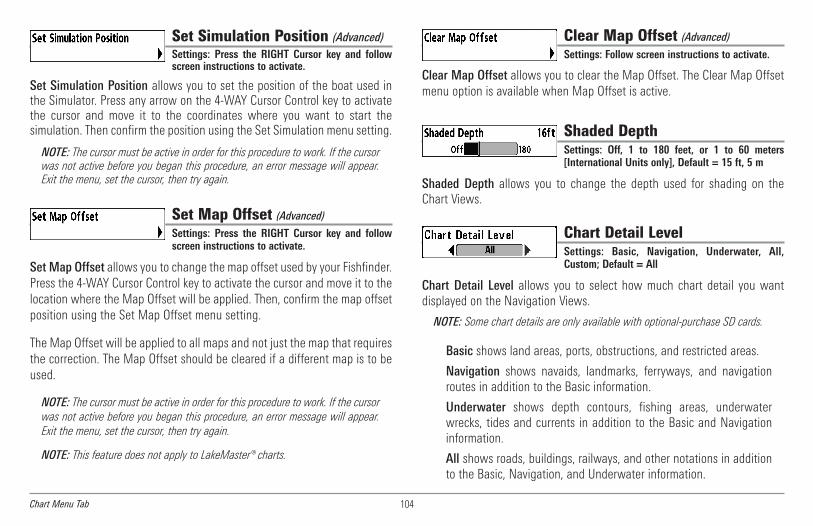
104
Set Simulation Position (Advanced)Settings: Press the RIGHT Cursor key and followscreen instructions to activate.
Set Simulation Position allows you to set the position of the boat used inthe Simulator. Press any arrow on the 4-WAY Cursor Control key to activatethe cursor and move it to the coordinates where you want to start thesimulation. Then confirm the position using the Set Simulation menu setting.
NOTE: The cursor must be active in order for this procedure to work. If the cursorwas not active before you began this procedure, an error message will appear.Exit the menu, set the cursor, then try again.
Set Map Offset (Advanced)Settings: Press the RIGHT Cursor key and followscreen instructions to activate.
Set Map Offset allows you to change the map offset used by your Fishfinder.Press the 4-WAY Cursor Control key to activate the cursor and move it to thelocation where the Map Offset will be applied. Then, confirm the map offsetposition using the Set Map Offset menu setting.
The Map Offset will be applied to all maps and not just the map that requiresthe correction. The Map Offset should be cleared if a different map is to beused.
NOTE: The cursor must be active in order for this procedure to work. If the cursorwas not active before you began this procedure, an error message will appear.Exit the menu, set the cursor, then try again.
NOTE: This feature does not apply to LakeMaster® charts.
Clear Map Offset (Advanced)Settings: Follow screen instructions to activate.
Clear Map Offset allows you to clear the Map Offset. The Clear Map Offsetmenu option is available when Map Offset is active.
Shaded DepthSettings: Off, 1 to 180 feet, or 1 to 60 meters[International Units only], Default = 15 ft, 5 m
Shaded Depth allows you to change the depth used for shading on theChart Views.
Chart Detail LevelSettings: Basic, Navigation, Underwater, All,Custom; Default = All
Chart Detail Level allows you to select how much chart detail you wantdisplayed on the Navigation Views.
NOTE: Some chart details are only available with optional-purchase SD cards.
Basic shows land areas, ports, obstructions, and restricted areas.
Navigation shows navaids, landmarks, ferryways, and navigationroutes in addition to the Basic information.
Underwater shows depth contours, fishing areas, underwaterwrecks, tides and currents in addition to the Basic and Navigationinformation.
All shows roads, buildings, railways, and other notations in additionto the Basic, Navigation, and Underwater information.
z
Chart Menu Tab

105
Custom (Advanced user mode) allows you to display or hidechart layers on the Navigation Views. The available chart layersinclude Navigable Canals, Boundaries, Restricted Areas, Coastline,Bridges, etc.
To customize the chart layers:
1. Select Chart Detail Level from the Chart Menu Tab. Press theRIGHT Cursor key to select Custom. Selecting Custom adds theCustom Chart Layers menu to the Chart menu.
2. Press the DOWN Cursor key to select Custom Chart Layers, andpress the RIGHT Cursor key to access the submenu.
3. Use the 4-WAY Cursor key to select a layer and turn it on(visible) or off (hidden). All changes take place immediately.
Map Borders, shown with optional-purchaseNavionics® Cartography with Custom Chart Layers
Other Points of Interest (POI)2
67
9
Navaids3Navigable Canals (thin, dark blue lines)4Roads5
Coastline 7
Restricted Area (dotted red lines) 6
Bridge (wavy red lines) 8Drying Lines 9
Isolated Danger: Boat Ramp 10
3
2
8
10
5
Map Borders1
4
1
Chart Menu Tab
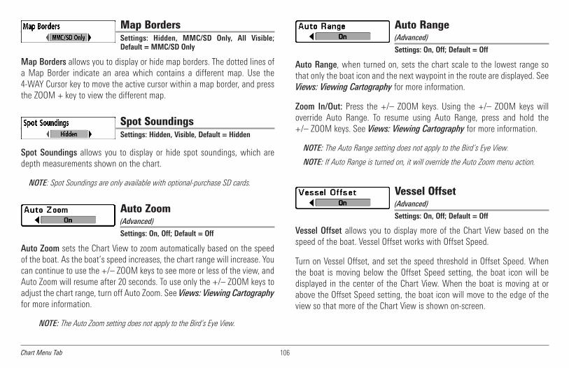
106
Map BordersSettings: Hidden, MMC/SD Only, All Visible;Default = MMC/SD Only
Map Borders allows you to display or hide map borders. The dotted lines ofa Map Border indicate an area which contains a different map. Use the4-WAY Cursor key to move the active cursor within a map border, and pressthe ZOOM + key to view the different map.
Spot SoundingsSettings: Hidden, Visible, Default = Hidden
Spot Soundings allows you to display or hide spot soundings, which aredepth measurements shown on the chart.
NOTE: Spot Soundings are only available with optional-purchase SD cards.
Auto Zoom(Advanced)
Settings: On, Off; Default = Off
Auto Zoom sets the Chart View to zoom automatically based on the speedof the boat. As the boat’s speed increases, the chart range will increase. Youcan continue to use the +/– ZOOM keys to see more or less of the view, andAuto Zoom will resume after 20 seconds. To use only the +/– ZOOM keys toadjust the chart range, turn off Auto Zoom. See Views: Viewing Cartographyfor more information.
NOTE: The Auto Zoom setting does not apply to the Bird’s Eye View.
Auto Range(Advanced)
Settings: On, Off; Default = Off
Auto Range, when turned on, sets the chart scale to the lowest range sothat only the boat icon and the next waypoint in the route are displayed. SeeViews: Viewing Cartography for more information.
Zoom In/Out: Press the +/– ZOOM keys. Using the +/– ZOOM keys willoverride Auto Range. To resume using Auto Range, press and hold the+/– ZOOM keys. See Views: Viewing Cartography for more information.
NOTE: The Auto Range setting does not apply to the Bird’s Eye View.
NOTE: If Auto Range is turned on, it will override the Auto Zoom menu action.
Vessel Offset(Advanced)
Settings: On, Off; Default = Off
Vessel Offset allows you to display more of the Chart View based on thespeed of the boat. Vessel Offset works with Offset Speed.
Turn on Vessel Offset, and set the speed threshold in Offset Speed. Whenthe boat is moving below the Offset Speed setting, the boat icon will bedisplayed in the center of the Chart View. When the boat is moving at orabove the Offset Speed setting, the boat icon will move to the edge of theview so that more of the Chart View is shown on-screen.
Chart Menu Tab

107
Offset Speed(with Vessel Offset turned on)
Settings: 5 to 60 mph, 5 to 50 kts, or 8 to 95 kph(International Models only); Default = 5 mph, 5 kts,8 kph
Offset Speed allows you to see more of the Chart View when the boat istraveling at or above the Offset Speed setting. Vessel Offset must be turnedon. See Vessel Offset for more information.
Contour Lines(optional-purchase LakeMaster® charts only)
Settings: Hidden, Visible; Default = Visible
Contour Lines sets whether the water contour lines are visible or hidden in theChart Views. Contour Lines are also affected by the Water Level Offset setting.
Depth Colors(optional-purchase LakeMaster® charts only)
Settings: Off, 1-10; Default = Off
Depth Color sets the depth shading in the Chart views to Off or Shaded.
Depth Highlight(optional-purchase LakeMaster® charts only)
Settings: Off, 1 - 180 feet, 1 - 30 fathoms, 1 - 60meters (International Models only); Default = Off
Depth Highlight allows you to highlight a depth setting in the chart views.The depth you set will be highlighted in green. Use Depth Highlight withDepth Highlight Range.
Depth Highlight Range (+/-)(optional-purchase LakeMaster® charts only)
Settings: 0 - 60 feet, 0 - 30 fathoms, 0 - 20 meters(International Models only); Default = 5 ft, 2m
Depth Highlight Range adjusts the range on each side of the highlighteddepth, when a Depth Highlight is active in the chart views.
Water Level Offset(optional-purchase LakeMaster® charts only)
Settings: -30 to +30 feet, -5 to +5 fathoms,-10 to +10 meters (International Models only);Default = 0
Water Level Offset allows you to change the level of the water being readfrom the control head. The displayed numbers on the Contour Lines willadjust from the Water Level Offset setting, and the water level offset will behighlighted in dark brown.
For example, if the lake is down 5 feet, set the Water Level Offset settingto -5.
For example, if you know a certain fish is holding at 18 - 20 feet, you canset the Depth Highlight at 19 feet, and the Depth Highlight Range a +/- 1foot. The view will show a green band from 18 - 20 feet.
Chart Menu Tab

108
Shallow Water Highlight(optional-purchase LakeMaster® charts only)
Settings: 0 - 30 feet, 0 - 5 fathoms, 0 - 10 meters(International Models only); Default = 0
Shallow Water Highlight allows you to select a minimum shallow depthsetting so that the depth is highlighted in red in the Chart Views.
Lake List(optional-purchase LakeMaster® charts only)
Settings: Press the RIGHT Cursor key to activate.
Lake List allows you to view the list of lakes included on the installed SD card.
Sort By: Highlight Sort By, and use the RIGHT or LEFT Cursor keys toselect a sort option for the list.
Scroll: Use the UP or DOWN Cursor keys to scroll through the list. Aseach lake is highlighted, you can view information about the lake inthe white box displayed on the screen.
Cursor To: Highlight a lake on the list and press the RIGHT Cursor keyto move the active cursor to the location you’ve chosen. You can thenmark waypoints, or press the GO TO key to start navigation toward awaypoint, or press the INFO key for more information.
Chart View with LakeMaster®
Water Level Offset1Depth Highlight2
Contour Lines 3Shallow Water Highlight 4
1 2
4
3
For example, if your boat has a draft of 3 feet, set the Shallow WaterHighlight feature to 3 feet, and the unit will draw a red band from 0 - 3 feet.Use this setting with Water Level Offset.
Chart Menu Tab

109
Setup Menu Tab
From any view, press the MENU key twice toaccess the tabbed Main Menu, then pressthe RIGHT Cursor key until the Setup tab isselected.
NOTE: Menu options will vary depending onwhich accessories are attached to the unit.
NOTE: Menu options can be expanded orsimplified by setting the User Mode toAdvanced or Normal. See Main Menu: UserMode for details.
Setup Menu, Advanced User Mode
Units - DepthSettings: Domestic Models: Feet, Fathoms;International Models: Meters, Feet, Fathoms;Default = Feet/Meters
Units - Depth selects the units of measure for all depth-related readouts.
Units - Temp(International Models only)
Settings: Celsius, Fahrenheit; Default = Celsius
Units - Temp selects the units of measure for all temperature-relatedreadouts.
Units - Distance(with Speed input only)
Settings: Domestic Models: Statute Miles, NauticalMiles, Default = Statute Miles; InternationalModels: Meters/Kilometers, Meters/NauticalMiles, Feet/Statute Miles, Feet/Nautical Miles,Default = Meters/Kilometers
Units - Distance selects the units of measure for all distance-relatedreadouts, and will appear in the menu if a Temp/Speed Accessory isconnected and the paddlewheel has moved at least once, or if the GPSReceiver is connected.
Setup Menu Tab

110
Units - Speed(with Speed input only)
Settings: Domestic Models: mph, kts; InternationalModels: kph, mph, kts; Default = mph/kph
Units - Speed selects the units of measure for speed-related readouts, andwill appear in the menu if a Temp/Speed Accessory is connected and thepaddlewheel has moved at least once, or if the GPS Receiver is connected.
User ModeSettings: Normal, Advanced; Default = Advanced
User Mode sets the menu system to Normal or Advanced. When set toNormal, the basic set of menu options are shown in the menu system. Whenset to Advanced (default setting), additional menu options are added to themenu system. SeeMain Menu: User Mode for details.
Language(International Models only)
Settings: Various, Default = English
Language selects the display language for menus.
Triplog Reset(with Speed input only)
Settings: Press the RIGHT Cursor key and followscreen instructions to activate.
Triplog Reset resets the Triplog to zero, and will appear in the menu if aTemp/Speed Accessory is connected and the paddlewheel has moved atleast once, or if the GPS Receiver is connected.
The Triplog provides the following information: timer for elapsed time,distance traveled since last reset, and average speed.
NOTE: See Views to find out how to display Triplog information on the screen.
Restore DefaultsSettings: Press the RIGHT Cursor key and followscreen instructions to activate.
Use this menu choice with caution!
Restore Defaults resets ALL menu settings to their factory defaults.
Format Nav DirectoriesSettings: Press the RIGHT Cursor key and followscreen instructions.
Use this menu choice with caution!
Format Nav Directories deletes ALL navigation data (waypoints, routes,tracks, and groups) and resets the navigation data directory in the WaypointManagement dialog box. You may need to reset the navigation directory ifyou’ve imported corrupted navigation data from an unknown source, whichcan cause the unit to malfunction (see SD Memory Card Slot: ImportNavigation Data). Contact our Customer Resource Center before using thismenu option.
NOTE: It is important to back up your control head’s data files periodically. Datafiles should also be saved to your PC before restoring the unit’s defaults orupdating the software. See your Humminbird® online account athumminbird.com and the Waypoint Management guide.
Setup Menu Tab

111
Select Readouts(Advanced)
Settings: Various, Default = Off
Select Readouts sets the information to display in each of the 5 fixed-position data windows arranged around the left and bottom edges of theSonar View screen. To leave the data window blank, select Off. See Views tochange the Select Readouts.
Data windows can display readouts from connectedequipment such as a GPS Receiver or Temp/Speedaccessory (optional-purchase required). Each datawindow can be empty or contain one of the followinginformation categories:
• Course • Time
• Depth • Time + Date
• Off • Timer
• Position • Triplog
• Aux. Temperature • Voltage
• Speed • Temperature
• Water Speed
Sonar, Side Imaging®, and Down Imaging® Views: All 5 readouts can becustomized.During navigation: Readout 1 can be customized, and Readouts 2 - 5 arefixed as follows: Readout 2 (Heading), Readout 3 (Bearing), Readout 4 (Split:Cross Track Error (XTE) and Distance To Go (DTG)), and Readout 5 (Split: TimeTo Go (TTG) and Speed).
Chart Views: Readouts 1, 3, and 4 can be customized. Readout 2 (Heading)and Readout 5 (Speed) are fixed and cannot be customized.
During navigation: Readout 1 can be customized, and Readouts 2 - 5 arefixed as follows: Readout 2 (Heading), Readout 3 (Bearing), Readout 4 (Split:Cross Track Error (XTE) and Distance To Go (DTG)), and Readout 5 (Split: TimeTo Go (TTG) and Speed).
Bird’s Eye View: Readout 1 - 4 are fixed as follows: Depth, Heading, Position(Lat/Lon), and Speed.
During navigation: There are two columns of fixed readouts. The first columnshows Depth, Time To Go (TTG), Position (Lat/Lon), and Speed. The secondcolumn shows Cross Track Error (XTE), Heading, Bearing, and Distance To Go(DTG).
Sonar View
Readout 11Readout 22
1
2
4
3
5
Readout 33Readout 44
Readout 55
Select Readouts
NOTE: The availability of the digital readout information corresponds with the viewselected, the accessory attached, and whether or not you are navigating.
Setup Menu Tab

112
Depth Offset(Advanced)
Settings:-10.0 to +10.0 feet or -3.0 to 3.0 meters[International models only], Default = 0.0, or Off
Depth Offset will adjust the digital depth readout to indicate depth from thewaterline or boats keel. Enter a positive vertical measurement from thetransducer to the waterline to read the depth from the waterline. Enter anegative vertical measurement from the transducer to keel to read the depthfrom the keel.
Aux. Temp Offset(Advanced, with Temp/Speed only)
Settings: -10.0 to +10.0 degrees, Default = 0
Aux Temp Offset will adjust the aux temperature readout (the temperatureon the optional-purchase temperature probe or Temp/Speed accessory) bythe amount entered.
Temp. Offset(Advanced)
Settings: -10.0 to +10.0 degrees, Default = 0, or Off
Temp Offset will adjust the temperature readout by the amount entered.
Speed Calibration(Advanced, with Temp/Speed only)
Settings: -20% to +20%, Default = 0%
Speed Calibration will adjust the speed readout by the percentage entered,and will appear in the menu if a Speed accessory is connected and thepaddlewheel has moved at least once.
Local Time Zone(Advanced)
Settings: Various; Default = EST [UTC-5] - EasternStandard Time
Local Time Zone selects your time zone in reference to the time reported bythe GPS receiver when Time+Date is selected as a Digital Readout on theSonar View (see Setup Menu Tab: Select Readouts).
Daylight Saving Time(Advanced)
Settings: Off, On; Default = Off
Daylight Saving Time adjusts the time display to account for local DaylightSaving Time when Time+Date is selected as a Digital Readout on the SonarView (see Setup Menu Tab: Select Readouts).
Selecting On adds one hour to the time display adjusted for your local timezone. Selecting Off leaves the time display as adjusted for your local timezone.
Position Format(Advanced)
Settings: dd.ddddd°, dd°mm.mmm', or dd°mm'ss";Default = dd°mm.mmm'
Position Format selects the format of the latitude and longitude positiondisplay.
Setup Menu Tab

113
GPS OutputSettings: 5 Hz, 10 Hz; Default = 5 Hz
GPS Output controls the frequency at which data from the GPS Receiver issent to the control head. Select 10 Hz to receive the most GPS updates onthe display.
Time Format(Advanced, International Models only)
Settings: 12 hour, 24 hour; Default = 12 hour
Time Format changes the time format used by the unit. Time Format selectsa 12 hour or 24 hour format for the time of day displayed when Time + Dateis selected as a Digital Readout on the Sonar View (see Setup Menu Tab:Select Readouts).
Date Format(Advanced, International Models only)
Settings: mm/dd/yy, dd.mm.yy, yy.mm.dd;Default = mm/dd/yy
Date Format changes the date format used by the unit. Date Format selectsthe format for the date display when Time + Date is selected as a DigitalReadout on the Sonar View (see Setup Menu Tab: Select Readouts).
Digits Format (Advanced)Settings: Small tenths, Large tenths, No tenths;Default = Small tenths
Digits Format adds a tenth decimal place to the readouts such asTemperature and Depth. Use the settings to change the display of thedecimal place or remove it from the digital readouts. Examples of thedifferent settings are displayed below. Also, see Select Readouts and Views.
NMEA 0183 Output (Advanced)Settings: Off, On; Default = Off
NMEA 0183 Output turns the NMEA* output on or off. NMEA Outputshould be turned On if you connect the NMEA Output wires of an accessoryGPS Receiver cable to another NMEA-compatible device, such as anautopilot.
*NMEA 0183 is a National Marine Electronics Association standard for datacommunication.
NOTE: A separate purchase of accessory AS-HHGPS may be required for theNMEA output function.
Small tenths Large tenths No tenths
Setup Menu Tab

114
The following NMEA sentences are output whenNMEAOutput is turned On:
DPT - DepthMTW - Water TemperatureGLL - Lat/Lon PositionGGA - GPS Fix DataRMC - Recommended Minimum Specific GNSS DataVTG - Course Over Ground and Ground SpeedZDA - Time and Date
When navigating, the following NMEA sentences are also output whenNMEA Output is turned On:
APB - Autopilot Sentence BBWR - Bearing and Distance to WaypointRMB - Recommended Minimum Navigation Info
Local SonarSettings: Off, On, Default = On
Local Sonar sets whether the Sonar views are shown in the View rotation.Select Off to deactivate Sonar and remove the Sonar Views from the Viewrotation.
NOTE: This feature may appear as either Sonar or Local Sonar, depending onyour model.
DemonstrationSettings: Off, Visible; Default = Visible
Demonstration controls whether the Demonstration Mode is visible or off.The Demonstration Mode appears on the screen if you don’t press any keysduring the warning screen at power up. Menu settings cannot be saved inDemonstration (see Power On and Start-Up Options Menu).
Sound ControlSettings: No Sounds, Alarms Only, All Sounds;Default = All Sounds
Sound Control allows you to set when the control head will beep or soundbecause of key presses and/or alarms.
Setup Menu Tab
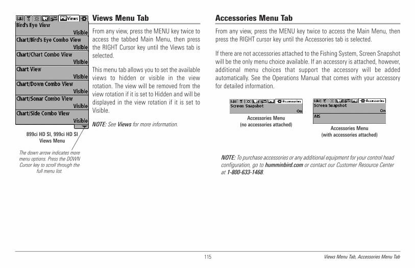
115
Views Menu Tab
From any view, press the MENU key twice toaccess the tabbed Main Menu, then pressthe RIGHT Cursor key until the Views tab isselected.
This menu tab allows you to set the availableviews to hidden or visible in the viewrotation. The view will be removed from theview rotation if it is set to Hidden and will bedisplayed in the view rotation if it is set toVisible.
NOTE: See Views for more information.
Accessories Menu Tab
From any view, press the MENU key twice to access the Main Menu, thenpress the RIGHT cursor key until the Accessories tab is selected.
If there are not accessories attached to the Fishing System, Screen Snapshotwill be the only menu choice available. If an accessory is attached, however,additional menu choices that support the accessory will be addedautomatically. See the Operations Manual that comes with your accessoryfor detailed information.
NOTE: To purchase accessories or any additional equipment for your control headconfiguration, go to humminbird.com or contact our Customer Resource Centerat 1-800-633-1468.
899ci HD SI, 999ci HD SIViews Menu
The down arrow indicates moremenu options. Press the DOWNCursor key to scroll through the
full menu list.
Accessories Menu(no accessories attached)
Accessories Menu(with accessories attached)
Views Menu Tab, Accessories Menu Tab

116
Screen Snapshot(optional-purchase SD Memory Cards only)
Settings: Off, On; Default = Off
Screen Snapshot activates the screen snapshot function. When ScreenSnapshot is enabled, pressing the MARK key creates a saved screensnapshot on the optional-purchase SD memory card installed in your unit’scard slot. All active menus, dialog boxes, warnings and messages arecaptured and saved automatically.
NOTE: You must have an optional-purchase SD memory card installed for theScreen Snapshot feature to work.
NOTE: If you use your SD memory card in two different Fishing System units thathave different screen sizes, the recordings made on one unit will still be presenton the card, but will be represented by the Unavailable icon (circle with a slantedline through it) on the Snapshot and Recording View on the other unit.
AIS(optional-purchase AIS equipment only)
Settings: Press the RIGHT Cursor key to activate.
Your Fishing System is compatible with AIS technology. This equipment mustbe purchased separately and connected properly to the control head for AISto be activated in your Fishing System.
When an AIS is connected to the Fishing System, AIS will appear as amenu option in the Accessories Menu Tab. AIS allows you to locate andmonitor other vessels, or Targets, within range of the VHF signal. The AISthen exchanges information with those targets, including vesselidentification, position, course, and speed.
Cargo Boat
Dredge Boat
Law Boat
Passenger Boat
Vessel Icons
Unidentified Boat
Sail Boat
Tow Boat
Tug Boat
NOTE: For more information, see Snapshot and Recording View andSnapshot and Recording X-Press™ Menu.
Accessories Menu Tab

117
As target information is received, the information is displayed in the ChartViews. In Bird’s Eye View, only the target position is displayed.
• Vessel Icons identify the type of target.
• Alarm & Red Vessel Icon identify a target that has exceeded theCPA (Closest Point of Approach) setting. The alarm sound and bannerwill display on the screen. Press any key to stop the alarm, but thevessel icon will continue to display as red until it is out of the CPAalarm zone.
• Available Targets: If the AIS has not received information from atarget within 10 minutes, the target will turn gray. If information isnot received after 15 minutes, the target will disappear from theview. Also, if there are several targets on the view, and a new targetmessage is received, the oldest target will disappear from the view.
• MMSI Tag (Maritime Mobile Service Identity) will be displayed if itis available for each target.
• Target Course Lines point in the direction of a vessel’s course. Thelength of the line can be adjusted in the Target Course Line settingin the AIS Submenu.
• Target Details: Information about each target can be found in theTarget List in the AIS submenu. You can also use the 4-WAY CursorControl key to move the active cursor onto a vessel icon. Press theINFO key to view available information, including target name,speed, course, latitude/longitude position, registration, call sign, andmore.
• AIS Submenu allows you to control and view AIS information.
AIS Submenu: The AIS submenu allows you totrack targets, receive alerts when targets arewithin the distance you set, and display targetsin Chart Views. In Bird’s Eye View, only theposition will be displayed.
Chart View with AIS
Your Boat icon Target Course Line1 3Target (Vessel in the area) Gray Target (information unavailable)2 4
1
2
4
3
Accessories Menu Tab

118
To Change Settings in the AIS Submenu:
Highlight AIS in the Accessories MENU Tab, and press the RIGHT Cursor keyto access the AIS Submenu.
Tracking Target sets targets and related information to be visible(On) or hidden (Off) in the Chart Views. In Bird’s Eye View, only targetposition will be displayed. (Settings: On, Off; Default = On)
CPA (Closest Point of Approach) Limits sets how close a vessel canapproach. The amount can be set in nautical miles or time. When thevessel has traveled past the set limit, the Vessel Icon will turn red inthe view and an alarm will sound. Press any key to turn off the alarm.Press the RIGHT Cursor key to open the dialog box.
CPA sets the closest point of approach, measured in nauticalmiles.
TCPA sets the closest point of approach, measured in time.Target List shows active targets and related information that isavailable with each AIS update. Press the RIGHT Cursor key to openthe Target List.
Sort: The list is sorted by MMSI number (if available). Targetswithout an MMSI will be shown at the bottom of the list.
Scroll: Use the UP or DOWN Cursor keys to scroll through thelist and highlight targets. Press and hold the DOWN Cursor keyto scroll through all the targets on the list quickly.
Target Highlight: Highlight a target on the Target List, and pressthe RIGHT Cursor key. The Target List will close and the activecursor will go to the target you highlighted. Press the EXIT keyto remove the active cursor from the screen.
Target Course Line turns course lines off or sets the amount of timerepresented on the target course line. The length of the course lineindicates the last known ship speed, while the direction of the arrowshows heading. (Settings: Off, 00:00 - 59:59; Default = 5:00)
MMSI Label (Maritime Mobile Service Identity) sets the MMSIlabel information to be Visible or Hidden. (Settings: Visible, Hidden;Default = Visible)
AIS Target List
Accessories Menu Tab

119
Maintenance
Your Humminbird® fishfinder is designed to provide years of trouble freeoperation with very little maintenance. Use the following procedures toensure your Humminbird® continues to deliver top performance.
Control Head MaintenanceIt is important to consider the following precautions when using yourHumminbird® control head:
• Chemicals, such as those found in bug spray and sunscreen, maycause permanent damage to the control head screen. Such damageis not covered by the warranty.
• NEVER leave the control head in a closed car or trunk. The hightemperatures generated in hot weather can damage the electronics.
Use the following information to keep the control head and screen clean.
• Screen: To clean the control head screen, use a mild soap (such as anon-abrasive liquid hand soap) and warm water. Wipe the screen drywith a soft cloth. Be careful to avoid scratching the screen. If waterspots remain, use a solution of water and vinegar.
WARNING! Do not use a chemical glass cleaner on the screen.Chemicals in the solution may cause cracking in the lens of the unit.
NOTE: Do not wipe the screen while dirt or grease is on the screen.
• Control Head: If the control head comes into contact with salt spray,wipe the affected surfaces with a cloth dampened with fresh water.
Transducer MaintenanceUse the following information to maintain the transducer operation.
• If your boat remains in the water for long periods of time, algae andother marine growth can reduce the effectiveness of the transducer.Periodically clean the face of the transducer with a mild, marine-safeand plastic-safe soap or solution.
NOTE: To clean the transducer, you may need to pivot the transducer up in thebracket.
• If your boat remains out of the water for a long period of time, it maytake some time to wet the transducer when it is returned to thewater. Small air bubbles can climb to the surface of the transducerand interfere with proper operation. These bubbles dissipate withtime, or you can wipe the face of the transducer with your fingersafter the transducer is in the water.
Maintenance

120
Troubleshooting
Before contacting the Humminbird® Customer Resource Center, please readthe following section. Taking the time to review these troubleshootingguidelines may allow you to solve a performance problem yourself, andtherefore avoid sending your unit back for repair.
Fishing System Doesn’t Power UpIf your Fishing System doesn’t power up, use the Installation Guide that alsocomes with it for specific confirmation details, making sure that:
• the power cable is properly connected to the control head
• the power cable is wired correctly, with red to positive batteryterminal and black to negative terminal or ground
• the fuse is operational
• the battery voltage of the power connector is at least 10 Volts.
Correct any known problems, including removing corrosion from the batteryterminals or wiring, or actually replacing the battery if necessary.
Fishing System Defaults to Simulatorwith a Transducer AttachedA connected and functioning transducer will cause the newly-startedFishing System to go into Normal operating mode automatically. If, whenyou power up the Fishing System, it goes into Simulator mode automatically,even though a transducer is already connected, this means that the controlhead is not detecting the transducer. Perform the following troubleshootingtasks:
• Using the Installation Guide that also comes with your FishingSystem, check to make sure that the transducer cable is securelyconnected to the Fishing System. Reconnect if necessary, and powerup the Fishing System again to see if this fixes the problem.
• Replace the non-functioning transducer with a known goodtransducer if available and power up the control head again.
• Check the transducer cable. Replace the transducer if the cable isdamaged or corroded.
Troubleshooting
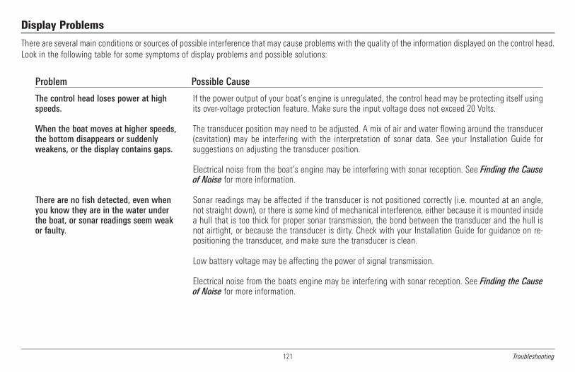
121
Display Problems
There are several main conditions or sources of possible interference that may cause problems with the quality of the information displayed on the control head.Look in the following table for some symptoms of display problems and possible solutions:
Problem Possible Cause
The control head loses power at highspeeds.
When the boat moves at higher speeds,the bottom disappears or suddenlyweakens, or the display contains gaps.
There are no fish detected, even whenyou know they are in the water underthe boat, or sonar readings seem weakor faulty.
If the power output of your boat’s engine is unregulated, the control head may be protecting itself usingits over-voltage protection feature. Make sure the input voltage does not exceed 20 Volts.
The transducer position may need to be adjusted. A mix of air and water flowing around the transducer(cavitation) may be interfering with the interpretation of sonar data. See your Installation Guide forsuggestions on adjusting the transducer position.
Electrical noise from the boat’s engine may be interfering with sonar reception. See Finding the Causeof Noise for more information.
Sonar readings may be affected if the transducer is not positioned correctly (i.e. mounted at an angle,not straight down), or there is some kind of mechanical interference, either because it is mounted insidea hull that is too thick for proper sonar transmission, the bond between the transducer and the hull isnot airtight, or because the transducer is dirty. Check with your Installation Guide for guidance on re-positioning the transducer, and make sure the transducer is clean.
Low battery voltage may be affecting the power of signal transmission.
Electrical noise from the boats engine may be interfering with sonar reception. See Finding the Causeof Noise for more information.
Troubleshooting

122
Finding the Cause of Noise
Electrical noise usually affects the display with many black dots at high speeds, and high sensitivity readings. One or more of the following sources can causenoise or interference:
Possible Source of Noise Isolation
Other electronic devices
The boat’s engine
Cavitation from the boat’s propeller
Turn off any nearby electronic devices to see if the problem goes away, then turn them on one at a timeto see if the noise re-appears.
To determine whether the boat’s engine is the source of the noise, increase the RPMs while the boatis in neutral and stationary to see if the noise increases proportionately; if noise appears when you revthe engine, the problem could be the spark plugs, alternator, or tachometer wiring. Replace the sparkplugs with resistor plugs, install an alternator filter, or route the control head power and transducercables away from the engine wiring.
Turbulence created by the propeller can cause noise; make sure the transducer is mounted at least 15”(38 cm) from the propeller, and that the water flows smoothly over the face of the transducer at all times.
Troubleshooting
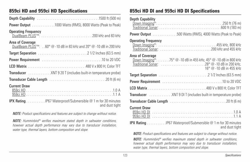
123
859ci HD and 959ci HD SpecificationsDepth Capability . . . . . . . . . . . . . . . . . . . . . . . . . . . . . . . . . . .1500 ft (500 m)
Power Output . . . . . . . . . . . . .1000 Watts (RMS), 8000 Watts (Peak to Peak)
Operating FrequencyDualBeam PLUS™: . . . . . . . . . . . . . . . . . . . . . . . . . . . . .200 kHz and 83 kHz
Area of CoverageDualBeam PLUS™: . .60° @ -10 dB in 83 kHz and 20° @ -10 dB in 200 kHz
Target Separation . . . . . . . . . . . . . . . . . . . . . . . . . . . .2 1/2 Inches (63.5 mm)
Power Requirement . . . . . . . . . . . . . . . . . . . . . . . . . . . . . . . . . .10 to 20 VDC
LCD Matrix . . . . . . . . . . . . . . . . . . . . . . . . . . . . . . . . .480 V x 800 H; Color TFT
Transducer . . . . . . . . . . . . .XNT 9 20 T (includes built-in temperature probe)
Transducer Cable Length . . . . . . . . . . . . . . . . . . . . . . . . . . . . . . . .20 ft (6 m)
Current Draw859ci HD . . . . . . . . . . . . . . . . . . . . . . . . . . . . . . . . . . . . . . . . . . . . . . . . .1.0 A959ci HD . . . . . . . . . . . . . . . . . . . . . . . . . . . . . . . . . . . . . . . . . . . . . . . . .1.1 A
IPX Rating . . . . . . . . . . .IP67 Waterproof/Submersible @ 1 m for 30 minutesand dust tight
NOTE: Product specifications and features are subject to change without notice.
NOTE: Humminbird® verifies maximum stated depth in saltwater conditions,however actual depth performance may vary due to transducer installation,water type, thermal layers, bottom composition and slope.
859ci HD DI and 959ci HD DI Specifications
Depth CapabilityDown Imaging®: . . . . . . . . . . . . . . . . . . . . . . . . . . . . . . . . . . . . .250 ft (76 m)Traditional Sonar: . . . . . . . . . . . . . . . . . . . . . . . . . . . . . . . . . . .600 ft (183 m)
Power Output . . . . . . . . . . . . . .500 Watts (RMS), 4000 Watts (Peak to Peak)
Operating FrequencyDown Imaging®: . . . . . . . . . . . . . . . . . . . . . . . . . . . . . . . . .455 kHz, 800 kHzTraditional Sonar: . . . . . . . . . . . . . . . . . . . . . . . . . . . . .200 kHz and 455 kHz
Area of CoverageDown Imaging®: . . . . . . .75° @ -10 dB in 455 kHz, 45° @ -10 dB in 800 kHzTraditional Sonar: . . . . . . . . . . . . . . . . . . . . . . . . .28° @ -10 dB in 200 kHz,
16° @ -10 dB in 455 kHz
Target Separation . . . . . . . . . . . . . . . . . . . . . . . . . . . .2 1/2 Inches (63.5 mm)
Power Requirement . . . . . . . . . . . . . . . . . . . . . . . . . . . . . . . . . .10 to 20 VDC
LCD Matrix . . . . . . . . . . . . . . . . . . . . . . . . . . . . . . . . .480 V x 800 H; Color TFT
Transducer . . . . . . . . . . . . .XNT 9 DI T (includes built-in temperature probe)
Transducer Cable Length . . . . . . . . . . . . . . . . . . . . . . . . . . . . . . . .20 ft (6 m)
Current Draw859ci HD DI . . . . . . . . . . . . . . . . . . . . . . . . . . . . . . . . . . . . . . . . . . . . . .1.0 A959ci HD DI . . . . . . . . . . . . . . . . . . . . . . . . . . . . . . . . . . . . . . . . . . . . . .1.1 A
IPX Rating . . . . . . . . . . .IP67 Waterproof/Submersible @ 1 m for 30 minutesand dust tight
NOTE: Product specifications and features are subject to change without notice.
NOTE: Humminbird® verifies maximum stated depth in saltwater conditions,however actual depth performance may vary due to transducer installation,water type, thermal layers, bottom composition and slope.
Specifications

124
899ci HD SI Specifications
Depth CapabilitySide Imaging®: . . . . . . . . . . . . . . . . . . . . . . . . . . . . . . . . . . . . . .150 ft (46 m)DualBeam PLUS™: . . . . . . . . . . . . . . . . . . . . . . . . . . . . . . . .1500 ft (500 m)
Power Output . . . . . . . . . . . . .1000 Watts (RMS), 8000 Watts (Peak to Peak)
Operating FrequencySide Imaging®: . . . . . . . . . . . . . . . . . . . . . . . . .200 kHz and 83 kHz, 455 kHz
Area of CoverageDualBeam PLUS™: . . .60°@ -10 dB in 83 kHz and 20°@ -10 dB in 200 kHzSide Imaging®: . . . . . . . . . .455 kHz: (2) 86° @ -10 db (180° Total Coverage)
Target Separation . . . . . . . . . . . . . . . . . . . . . . . . . . . .2 1/2 Inches (63.5 mm)
Power Requirement . . . . . . . . . . . . . . . . . . . . . . . . . . . . . . . . . .10 to 20 VDC
LCD Matrix . . . . . . . . . . . . . . . . . . . . . . . . . . . . . . . . .480 V x 800 H; Color TFT
Transducer . . . . . . . . . .XNT 9 SI 180 T (includes built-in temperature probe)
Transducer Cable Length . . . . . . . . . . . . . . . . . . . . . . . . . . . . . . . .20 ft (6 m)
Current Draw . . . . . . . . . . . . . . . . . . . . . . . . . . . . . . . . . . . . . . . . . . . . . .1.0 A
IPX Rating . . . . . . . . . . .IP67 Waterproof/Submersible @ 1 m for 30 minutesand dust tight
NOTE: Product specifications and features are subject to change without notice.
NOTE: Humminbird® verifies maximum stated depth in saltwater conditions,however actual depth performance may vary due to transducer installation,water type, thermal layers, bottom composition and slope.
999ci HD SI Specifications
Depth CapabilitySide Imaging®: . . . . . . . . . . . . . . . . . . . . . . . . . . . . . . . . . . . . . .150 ft (46 m)DualBeam PLUS™: . . . . . . . . . . . . . . . . . . . . . . . . . . . . . . . .1500 ft (500 m)
Power Output . . . . . . . . . . . . .1000 Watts (RMS), 8000 Watts (Peak to Peak)
Operating FrequencySide Imaging®: . . . . . . . . . . . . . . . . . .200 kHz and 83 kHz, 455 kHz, 800 kHz
Area of CoverageDualBeam PLUS™: . . .60°@ -10 dB in 83 kHz and 20°@ -10 dB in 200 kHzSide Imaging®: . . . . . . . . . .455 kHz: (2) 86° @ -10 db (180° Total Coverage)
800 kHz: (2) 55° @ -10 db (130° Total Coverage)
Target Separation . . . . . . . . . . . . . . . . . . . . . . . . . . . .2 1/2 Inches (63.5 mm)
Power Requirement . . . . . . . . . . . . . . . . . . . . . . . . . . . . . . . . . .10 to 20 VDC
LCD Matrix . . . . . . . . . . . . . . . . . . . . . . . . . . . . . . . . .480 V x 800 H; Color TFT
Transducer . . . . . . . .XHS 9 HDSI 180 T (includes built-in temperature probe)
Transducer Cable Length . . . . . . . . . . . . . . . . . . . . . . . . . . . . . . . .20 ft (6 m)
Current Draw . . . . . . . . . . . . . . . . . . . . . . . . . . . . . . . . . . . . . . . . . . . . . .1.1 A
IPX Rating . . . . . . . . . . .IP67 Waterproof/Submersible @ 1 m for 30 minutesand dust tight
NOTE: Product specifications and features are subject to change without notice.
NOTE: Humminbird® verifies maximum stated depth in saltwater conditions,however actual depth performance may vary due to transducer installation,water type, thermal layers, bottom composition and slope.
Specifications
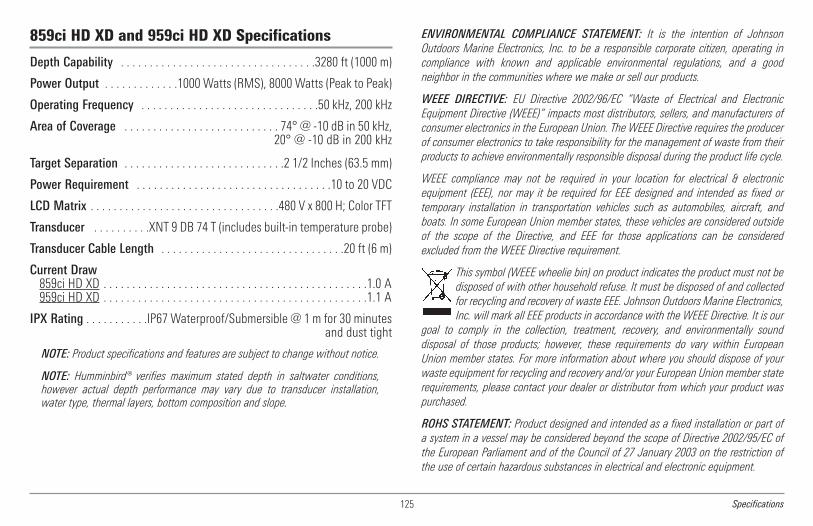
125
859ci HD XD and 959ci HD XD Specifications
Depth Capability . . . . . . . . . . . . . . . . . . . . . . . . . . . . . . . . . .3280 ft (1000 m)
Power Output . . . . . . . . . . . . .1000 Watts (RMS), 8000 Watts (Peak to Peak)
Operating Frequency . . . . . . . . . . . . . . . . . . . . . . . . . . . . . . .50 kHz, 200 kHz
Area of Coverage . . . . . . . . . . . . . . . . . . . . . . . . . . . 74° @ -10 dB in 50 kHz,20° @ -10 dB in 200 kHz
Target Separation . . . . . . . . . . . . . . . . . . . . . . . . . . . .2 1/2 Inches (63.5 mm)
Power Requirement . . . . . . . . . . . . . . . . . . . . . . . . . . . . . . . . . .10 to 20 VDC
LCD Matrix . . . . . . . . . . . . . . . . . . . . . . . . . . . . . . . . .480 V x 800 H; Color TFT
Transducer . . . . . . . . . .XNT 9 DB 74 T (includes built-in temperature probe)
Transducer Cable Length . . . . . . . . . . . . . . . . . . . . . . . . . . . . . . . .20 ft (6 m)
Current Draw859ci HD XD . . . . . . . . . . . . . . . . . . . . . . . . . . . . . . . . . . . . . . . . . . . . . .1.0 A959ci HD XD . . . . . . . . . . . . . . . . . . . . . . . . . . . . . . . . . . . . . . . . . . . . . .1.1 A
IPX Rating . . . . . . . . . . .IP67 Waterproof/Submersible @ 1 m for 30 minutesand dust tight
NOTE: Product specifications and features are subject to change without notice.
NOTE: Humminbird® verifies maximum stated depth in saltwater conditions,however actual depth performance may vary due to transducer installation,water type, thermal layers, bottom composition and slope.
ENVIRONMENTAL COMPLIANCE STATEMENT: It is the intention of JohnsonOutdoors Marine Electronics, Inc. to be a responsible corporate citizen, operating incompliance with known and applicable environmental regulations, and a goodneighbor in the communities where we make or sell our products.
WEEE DIRECTIVE: EU Directive 2002/96/EC “Waste of Electrical and ElectronicEquipment Directive (WEEE)” impacts most distributors, sellers, and manufacturers ofconsumer electronics in the European Union. The WEEE Directive requires the producerof consumer electronics to take responsibility for the management of waste from theirproducts to achieve environmentally responsible disposal during the product life cycle.
WEEE compliance may not be required in your location for electrical & electronicequipment (EEE), nor may it be required for EEE designed and intended as fixed ortemporary installation in transportation vehicles such as automobiles, aircraft, andboats. In some European Union member states, these vehicles are considered outsideof the scope of the Directive, and EEE for those applications can be consideredexcluded from the WEEE Directive requirement.
This symbol (WEEE wheelie bin) on product indicates the product must not bedisposed of with other household refuse. It must be disposed of and collectedfor recycling and recovery of waste EEE. Johnson Outdoors Marine Electronics,Inc. will mark all EEE products in accordance with the WEEE Directive. It is our
goal to comply in the collection, treatment, recovery, and environmentally sounddisposal of those products; however, these requirements do vary within EuropeanUnion member states. For more information about where you should dispose of yourwaste equipment for recycling and recovery and/or your European Union member staterequirements, please contact your dealer or distributor from which your product waspurchased.
ROHS STATEMENT: Product designed and intended as a fixed installation or part ofa system in a vessel may be considered beyond the scope of Directive 2002/95/EC ofthe European Parliament and of the Council of 27 January 2003 on the restriction ofthe use of certain hazardous substances in electrical and electronic equipment.
Specifications

NOTE: This product uses the Linux operating system. This portion of the software is freesoftware; you can redistribute it and/or modify it under the terms of the GNU GeneralPublic License as published by the Free Software Foundation; either version 2 of theLicense, or (at your option) any later version. This program is distributed in the hope thatit will be useful, but WITHOUT ANY WARRANTY; without even the implied warranty ofMERCHANTABILITY or FITNESS FOR A PARTICULAR PURPOSE. See the GNU GeneralPublic License for more details.
You may receive a copy of the GNU General Public License along with this program; if not,write to the Free Software Foundation, Inc., 51 Franklin Street, Fifth Floor, Boston, MA02110-1301 USA.
To receive a free copy of the Linux software used in this system, please send a letter ofrequest* with the following information:
Name (First & Last)Phone NumberE-mail AddressMailing AddressHumminbird® serial number(Your Humminbird® unit must be registered athumminbird.com/support/productregistration.aspx.)
Shipping and Handling: We can only accept requests that include a money order in theamount of $9.99 to cover shipping and handling. Please allow 4-6 weeks for processing.
Send the letter of request* to the following address:Linux Software RequestHumminbird678 Humminbird LaneEufaula, AL 36027
*NOTE: A copy of the Linux operating system is not required to upgrade your fishingsystem. The Humminbird® application software and control head include a separateservice warranty. Please see humminbird.com and the separate warranty card includedwith your unit for details.
Copyright © 2000 Caldera Systems, Inc. All rights reserved.
Redistribution and use in source and binary forms, with or without modification, arepermitted provided that the following conditions are met:
• Redistributions of source code must retain the above copyright notice, this listof conditions and the following disclaimer.
• Redistributions in binary form must reproduce the above copyright notice, thislist of conditions and the following disclaimer in the documentation and/orother materials provided with the distribution.
• Neither the name of Caldera Systems nor the names of its contributors may beused to endorse or promote products derived from this software withoutspecific prior written permission.
THIS SOFTWARE IS PROVIDED BY THE COPYRIGHT HOLDERS AND CONTRIBUTORS “ASIS” AND ANY EXPRESS OR IMPLIED WARRANTIES, INCLUDING, BUT NOT LIMITED TO,THE IMPLIED WARRANTIES OF MERCHANTABILITY AND FITNESS FOR A PARTICULARPURPOSE ARE DISCLAIMED. IN NO EVENT SHALL THE CALDERA SYSTEMS ORCONTRIBUTORS BE LIABLE FOR ANY DIRECT, INDIRECT, INCIDENTAL, SPECIAL,EXEMPLARY, OR CONSEQUENTIAL DAMAGES (INCLUDING, BUT NOT LIMITED TO,PROCUREMENT OF SUBSTITUTE GOODS OR SERVICES; LOSS OF USE, DATA, OR PROFITS;OR BUSINESS INTERRUPTION) HOWEVER CAUSED AND ON ANY THEORY OF LIABILITY,WHETHER IN CONTRACT, STRICT LIABILITY, OR TORT (INCLUDING NEGLIGENCE OROTHERWISE) ARISING IN ANY WAY OUT OF THE USE OF THIS SOFTWARE, EVEN IFADVISED OF THE POSSIBILITY OF SUCH DAMAGE.
126Specifications
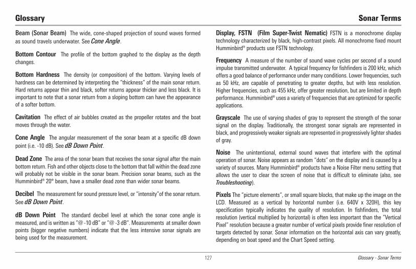
Beam (Sonar Beam) The wide, cone-shaped projection of sound waves formedas sound travels underwater. See Cone Angle.
Bottom Contour The profile of the bottom graphed to the display as the depthchanges.
Bottom Hardness The density (or composition) of the bottom. Varying levels ofhardness can be determined by interpreting the “thickness“ of the main sonar return.Hard returns appear thin and black, softer returns appear thicker and less black. It isimportant to note that a sonar return from a sloping bottom can have the appearanceof a softer bottom.
Cavitation The effect of air bubbles created as the propeller rotates and the boatmoves through the water.
Cone Angle The angular measurement of the sonar beam at a specific dB downpoint (i.e. -10 dB). See dB Down Point.
Dead Zone The area of the sonar beam that receives the sonar signal after the mainbottom return. Fish and other objects close to the bottom that fall within the dead zonewill probably not be visible in the sonar beam. Precision sonar beams, such as theHumminbird® 20° beam, have a smaller dead zone than wider sonar beams.
Decibel The measurement for sound pressure level, or “intensity”of the sonar return.See dB Down Point.
dB Down Point The standard decibel level at which the sonar cone angle ismeasured, and is written as “@ -10 dB” or “@ -3 dB“. Measurements at smaller downpoints (bigger negative numbers) indicate that the less intensive sonar signals arebeing used for the measurement.
Display, FSTN (Film Super-Twist Nematic) FSTN is a monochrome displaytechnology characterized by black, high-contrast pixels. All monochrome fixed mountHumminbird® products use FSTN technology.
Frequency A measure of the number of sound wave cycles per second of a soundimpulse transmitted underwater. A typical frequency for fishfinders is 200 kHz, whichoffers a good balance of performance under many conditions. Lower frequencies, suchas 50 kHz, are capable of penetrating to greater depths, but with less resolution.Higher frequencies, such as 455 kHz, offer greater resolution, but are limited in depthperformance. Humminbird® uses a variety of frequencies that are optimized for specificapplications.
Grayscale The use of varying shades of gray to represent the strength of the sonarsignal on the display. Traditionally, the strongest sonar signals are represented inblack, and progressively weaker signals are represented in progressively lighter shadesof gray.
Noise The unintentional, external sound waves that interfere with the optimaloperation of sonar. Noise appears as random “dots“ on the display and is caused by avariety of sources. Many Humminbird® products have a Noise Filter menu setting thatallows the user to clear the screen of noise that is difficult to eliminate (also, seeTroubleshooting).
Pixels The “picture elements“, or small square blocks, that make up the image on theLCD. Measured as a vertical by horizontal number (i.e. 640V x 320H), this keyspecification typically indicates the quality of resolution. In fishfinders, the totalresolution (vertical multiplied by horizontal) is often less important than the “VerticalPixel“ resolution because a greater number of vertical pixels provide finer resolution oftargets detected by sonar. Sonar information on the horizontal axis can vary greatly,depending on boat speed and the Chart Speed setting.
127
Glossary Sonar Terms
Glossary - Sonar Terms

Power Output The amount of sound energy emitted into the water by thetransducer’s transmitter. Power output is measured using either RMS (Root MeanSquare) or P-T-P (Peak-to-Peak) measurement systems. Either method is acceptable,but it is important when comparing power outputs, to make sure that the samemeasurement system is being used for both outputs, because P-T-P numbers are 8times higher than RMS numbers. Greater power output allows the sonar signal topenetrate through weeds and thermoclines, reach deeper depths and operate moreeffectively in noisy environments, such as when the boat is running at high speed.
Pulse Width (Pulse Length) The length of time that a sonar sound burst istransmitted into the water. Shorter pulse widths provide better target separation, butcannot travel to great depths. Longer pulse widths provide better depth penetration,but result in poorer target separation. Humminbird® varies pulse width based on depthto optimize both target separation and depth performance. See Target Separation.
Second Return Describes the appearance of a second sonar return below theprimary sonar return (bottom contour) at exactly twice the true depth. The secondreturn is caused by the same sonar energy bouncing off the bottom once, reboundingto the water surface and then traveling back down to the bottom to be reflected again.Second returns are more common in shallow water and over hard bottoms; it ispossible to see a third sonar return under some circumstances. The second returnprovides useful information to help determine bottom hardness, as areas with harderbottoms will generally create a second return. The second return can be used as aguide to set Sensitivity when in shallower water.
SONAR (SOund and NAvigation Ranging) Sonar technology uses precision soundbursts transmitted underwater to determine the distance and other attributes of objectsin the water. Distance can be determined because the speed of sound in water isconstant, and the time for the signal to return is measured. Sound also travels veryquickly underwater, making sonar a responsive, cost-effective tool. Sonar is the basictechnology behind all recreational and commercial fishfinding and depthfinding devices.
Sonar Update Rate The number of times per second that the transducer’stransmitter/receiver sends and receives sonar signals. A very fast sonar update ratecollects more information and provides a more detailed image of the bottom, fish, andstructure. Many Humminbird® units operate at up to 40 times per second when insingle frequency operation. Due to the limitation of the speed of sound in water, theupdate rate begins to slow as depth increases to deeper than 50 feet. In very shallowwater (less than 10 feet), however, update rates as much as 60 times per second canbe achieved.
Speed The rate at which the boat moves through the water. Boat speed can bemeasured as Speed Over Ground or Speed Through Water. Speed Over Ground isprovided by GPS, and is the measurement of the boats progress across a givendistance. Speed Through Water is provided by a speed paddlewheel, and is themeasurement of the flow past the boat, which may vary depending on current speedand direction. Speed Through Water is most critical for anglers using downriggers, asit impacts the running depth of the down riggers. Speed Over Ground is optimal fornavigation, as accurate destination times can be derived from this measurement.Humminbird® products allow for input and display of both sources.
Structure A general term for objects on the bottom that present a discontinuity andare a likely attractor for fish. This includes bottom contour features (drop-offs, humps,and holes), standing structure (stumps, timbers, brush piles), and a wide range ofother potential objects (sunken boats, reefs).
Surface Clutter A phenomenon where sonar returns are reflected off of tiny objectsnear the surface of the water, including algae and even air bubbles. Typically, saltwaterenvironments have significantly greater surface clutter than freshwater due tocontinuous wind and wave action that causes aeration at the surface.
Target Separation The measurement of minimum distance that a fishfinder needs tobe able to recognize two very close objects as two distinct targets (i.e. two fishhanging very close, or a fish hanging very close to structure). Humminbird® fishfinders
128
Glossary Sonar Terms
Glossary - Sonar Terms

provide a very good 2 1/2 inches of target separation in shallower than 100 feet ofdepth. Target separation decreases as depth increases due to the need for longer PulseWidth to achieve greater depth. See Pulse Width.
Thermoclines Water layer(s) of distinctly different temperatures that create a sonarreflection due to the density of the differing water temperatures. Typically athermocline will appear as a continuous band across the display at some distanceabove the bottom contour. Thermoclines are of interest to anglers because fish willsuspend above or below the thermocline as they seek the optimum temperature andoxygen levels.
Time Variable Gain (TVG) A processing step applied to the sonar return to“normalize“ the data so that objects of equal size (i.e. fish) appear to be the same size,even if they are separated by a good distance.
Transducer The transducer is part of the sonar system, which mounts on the boatand is in contact with the water, that converts the electrical energy from thetransmitter into sound energy, and that forms the sonar beam in turn. Internally, thetransducer consists of one or more piezo electric disks that expand by very minuteamounts to create the sound wave. This element also works in reverse, converting thereturned sound energy back into an electrical signal that the receiver interprets. SeeSONAR.
Zoom A feature that focuses on a smaller area of the bottom to provide enhancedresolution. With enhanced resolution, the angler can more easily see fish hanging instructure or multiple fish hanging close together.
Zoom, Bottom Lock Bottom Lock Zoom is a feature that focuses on a smaller areajust above the bottom to provide enhanced resolution. Unlike regular zoom, itcontinuously graphs the bottom at a constant point on the display regardless ofchanges in depth. This “flattens“ out the bottom contour, but is effective at showingfish on or near the bottom, and is preferred by many saltwater anglers.
Acquisition Time The length of time that a GPS receiver typically takes to determinea position from at least three satellites. Humminbird® GPS receivers provide very fastacquisition times (under one minute), permitting users to get out on the water faster.
Altitude The height measurement above sea level. Altitude is a measurement thatcan be provided by GPS.
Bearing (BRG) The direction to a destination waypoint measured in degrees fromNorth (i.e. 321°, where 000° is North, 090° East, 180° is South, 270° is West).
Chartplotter A navigation device that shows Present Position on a Map, along withTracks, Waypoints, and Routes. All Chartplotters are also considered Trackplotters.
Cold Start The procedure that a GPS receiver must perform when it does not havehistorical information regarding its current location. This procedure typically lasts forseveral minutes, and may be experienced upon first power up of the receiver, or if thereceiver has been moved a great distance.
Course Over Ground (COG) The current direction the boat is traveling measured indegrees from North (i.e. 321°, where 000° is North, 090° East, 180° is South, 270° isWest). When the Course Over Ground is equal to Bearing, the boat is said to be “OnCourse” and will arrive at the destination in the most efficient manner. COG is oftenconfused with Heading. See Heading.
Cross Track Error (XTE) The straight-line distance of the boat from the intendedTrack. XTE measures how far the boat is off course and also triggers the Off CourseAlarm. See Track.
Differential GPS (DGPS) A system used to improve the position accuracy of theDepartment of Defense GPS through the use of secondary “correction signals”broadcast from ground stations around the coastal United States and on some inlandwaterways. These correction signals are provided by the USCG and received by anauxiliary Differential Beacon Receiver (DBR) that connects to the GPS receiver. The
129
Glossary Sonar Terms Glossary GPS & Navigation Terms
Glossary - Sonar Terms, GPS & Navigation Terms

advent of WAAS has largely negated the need for the added expense of a DBR in theUnited States.
Distance To Go The straight-line distance between Present Position and theDestination Waypoint. DTG and SOG (Speed Over Ground) are used to calculate TimeTo Go. See Time to Go and Speed Over Ground.
Estimated Position Error (EPE) A calculation that indicates the potential positioninaccuracy the user may experience due to a variety of GPS factors which includesatellite position in the sky, signal strength, and others factors.
Fix Type Indicates whether the GPS receiver is providing 2D fix or 3D fix. A 2D fixrequires only three satellites and provides only latitude and longitude. A 3D fix requiresfour or more satellites, and provides latitude, longitude, and altitude.
GPS (Global Positioning System) GPS provides accurate position (latitude,longitude, altitude) information virtually anywhere on the earth through satellitetechnology and personal receivers on the ground. See How GPS Works.
Heading The direction the boat is pointing and is measured in degrees (i.e. 321°,where 000° is North, 090° East, 180° is South, 270° is West). Due to wind and waves,the boat is often traveling in a slightly different direction than it is heading, andtherefore Heading is often confused with Course Over Ground. See Course OverGround.
Map Datum Refers to a particular survey of the earth’s surface that was referencedwhen creating a chart (i.e. WGS84). It is important to select the correct Map Datumsetting in your fishfinder when comparing GPS position to a paper chart to avoid slightposition inaccuracies. Almost all electronic charts use the WGS84 Map Datum andtherefore, they do not require setting changes.
MMC (Multi Media Card) AnMMC is a postage stamp-sized memory device usedto store electronic data such a maps, waypoints, routes, and other information. MMC
is a very rugged format suitable for the marine environment, but it is not waterproof.MMC is the same format that many digital cameras use. See SD.
North, Magnetic The principle reference point of the compass (i.e. North is 000°).Magnetic North relies on the earth’s magnetic field to align a metal pointer generallytowards True North. However, due to local variations in the earth’s magnetic fieldaround the globe, the difference between True North and Magnetic North can begreater than 10°. See True North.
North, True The principle reference point of the compass (i.e. North is 000°). TrueNorth uses the axis of the rotation of the earth as the reference for North and isconstant for all points on the earth. Most GPS units default to True North as thesetting. The GPS heading may vary from the boat compass heading because thecompass uses Magnetic North. SeeMagnetic North.
Present Position The current location (latitude, longitude) determined by GPS. ThePresent Position is indicated on-screen by a directional boat icon if the boat is movingor a round symbol if the boat is stationary.
Route A series of waypoints linked together in a specific sequence to define anavigation path between two points, and saved in the fishfinder’s memory. Routes areoften used when frequently traveling between two or more locations because it is afaster and more accurate method than repeatedly selecting individual waypoints eachtime one travels through the same area. Routes consist of a Start Waypoint, an EndWaypoint, and a series of waypoints in between. Users can begin navigation at thebeginning, the end (to run the route in reverse) or at any waypoint in between. SeeWaypoint.
SD (Secure Digital) An SD card is virtually identical in function to an MMC;however, the speed at which information can be accessed is generally faster, thestorage capacity is generally larger, and the card has security features which can beused to prevent extracting the data from the card. SD is the same format that manydigital cameras use. SeeMMC.
130
Glossary GPS & Navigation Terms
Glossary - GPS & Navigation Terms

Selective Availability (SA) A GPS system “feature” that can be implemented bythe U.S. Department of Defense (DoD) to degrade the accuracy of GPS positioninginformation. With SA active, the GPS is accurate to within 100 meters 95% of the time.With SA inactive, the GPS is accurate to within 45 meters 95% of the time. Currently,SA is inactive and the consumer can enjoy the greater precision GPS provides;however, the DoD reserves the right to activate SA at any time.
Speed Over Ground (SOG) The measurement of the boat’s progress across a givendistance and the speed measurement provided by GPS. An alternate, Speed ThroughWater, is provided by a speed paddlewheel, and is the measurement of the flow pastthe boat, which may vary depending on current speed and direction. Speed OverGround is optimal for navigation because accurate destination times can be derivedfrom this measurement. Humminbird® products allow for input and display of bothspeed measurements.
Time To Go (TTG) The estimated time required to reach the destination waypoint.TTG is calculated using the SOG and DTG. See SOG and DTG.
Track A series of saved points that define the past path of the boat. These TrackPoints are saved at regular time intervals. Tracks are a useful and quick method to seewhere you’ve been, and an easy guide to follow to get you back to the starting point.Generally, all GPS units have a limited number of Track Points that can be saved beforethe unit runs out of memory and begins erasing the first track points saved. Becauseof this, the user can adjust the Track Point Interval menu to increase the amount oftime between when points are saved, and thus extend the distance covered by a track.Tracks can also be permanently saved to memory and re-displayed at the user’s option.
Track Line (TRK) The planned line of travel between two waypoints, and itrepresents the most efficient path between the two points because it is a straight line.The TRK is measured in degrees (i.e. 321°, where 000° is North, 090° East, 180° isSouth, 270° is West). See Cross Track Error and Course Over Ground.
Trackplotter A navigation device that shows Present Position, along with Track,Waypoint, and Routes, but NO MAP in the background. See Chartplotter.
Trolling Grid A Humminbird® feature that displays a precise reference grid around awaypoint. This grid is used as a guide pattern for trolling around a specific area toassure a more efficient and complete coverage of that area.
UTC (Universal Time Constant)UTC is the “standard time” used in navigation andis the local time in Greenwich England. (UTC is equivalent to Greenwich Mean Time(GMT)).
WAAS (Wide Area Augmentation System)WAAS is complementary technologyto GPS that provides enhanced accuracy through correction signals broadcast fromFederal Aviation Administration WAAS satellites stationed over the USA. Thesesecondary signals are automatically received by the standard Humminbird® GPSReceiver. With WAAS signal, GPS accuracy is improved to within 3 meters 95% of thetime. Outside the United States, regional governmental coalitions have created similarsystems such as EGNOS (Europe) and MSAS (Japan).
Waypoint The saved location (latitude, longitude) of a point of interest that is storedin a GPS receiver’s memory. This can include a marker buoy, dock, fishing hole, oranywhere else the user may want to return to. Humminbird® products offer the abilityto name and assign a symbol to the saved location. Depth, Date, and Time of Day whenthe waypoint was created is also saved.
Waypoint Target A Humminbird® feature that displays a precise “bull’s eye” arounda selected waypoint. This bull’s eye is used to easily monitor boat position relative toa waypoint, and is useful for fishing over submerged structure. WithWaypoint Targets,a quick look at the screen lets you know how far off the waypoint the boat has drifted.
131
Glossary GPS & Navigation Terms
Glossary - GPS & Navigation Terms

NOTE: If you are reproducing or printing this template from an electronic file,start with the following print settings: Scale = None, Paper = 8.5 x 11 inches,Layout = Landscape. Confirm that the template matches the transducer bracketslots and adjust the print as needed.
132
Appendix A Side Imaging® Transducer Mounting Template (XHS 9 HDSI 180 T)
Appendix

133
Contact Humminbird®
Contact the Humminbird® Customer Resource Centerin any of the following ways:
By Telephone(Monday - Friday 8:00 a.m. to 4:30 p.m. Central Standard Time):
1-800-633-1468
By e-mail(typically we respond to your e-mail within three business days):
For direct shipping, our address is:
HumminbirdService Department678 Humminbird LaneEufaula, AL 36027 USA