8 stages of construction - planning & …...2016/09/08 · 8 stages of construction from...
TRANSCRIPT
PREMIERGUARANTEE.CO.UK
8 STAGES OFCONSTRUCT ION
From Foundations to Surface Finishes, and everything in between, the construction process is a lengthy one that requires a lot of time, effort and some very precise and meticulous planning. Bricks, sweat, and (possibly) tears.
Throughout this eBook, we will take you through each stage of construction – Foundations, Substructure, Superstructure, Roofs, First and Second Fix, Surface Finishes and External Works – with a number of technical articles that outline common issues faced within each stage, with suggested ways to overcome these issues including best practice methods.
Reading this eBook might take you around half your lunch break. Completing a build, start to finish, might take significantly longer! We know how testing completing a project can be, and whilst we hope you don’t run into many issues during your build, the technical articles within this eBook are designed to help you combat them if you do, or better prepare before starting. The Premier Guarantee technical team are here to help, and their insight into the industry is second-to-none. If you can trust anyone when it comes to the issues within these digital pages, it’s them. In the first of our technical articles, we are going to be looking at trees and the affect they can have on the foundations of your build, with issues such as soil, moisture and climate conditions all being discussed. Our substructure article will see our Managing Director, Rob Clay-Parker, highlight the importance of perimeter drainage channels to ‘Type C’ basement waterproofing systems. Following this, we’ll show you how to ‘Avoid Those Unwanted Cracks’ when it comes to building with masonry in our superstructure technical blog.
Moving on to Roofs and, again, Rob Clay-Parker will be advising on how to avoid water damage with some helpful tips from the technical team. After which, in our first and second fix stage article, we will be outlining Approved Document M, which centres on the positioning of electrical consumer units in new homes, and how to comply with its standards.
Next, we touch on surface finishes and what the change in BS 5534:2014 will mean for roof tiling and, lastly, we finish with external works, which will see you taken through a step-by-step guide on how to create a level threshold for an entrance to a dwelling. The subjects covered within this eBook are just some of many complicated and technical issues that developers and builders can come up against. Here at Premier Guarantee, we like to leave no stone unturned so, if you have got a technical query or need to find out which warranty you need and why, give the team a call on 08444 120 888 or visit www.premierguarantee.co.uk
8 STAGES OFCONSTRUCT ION

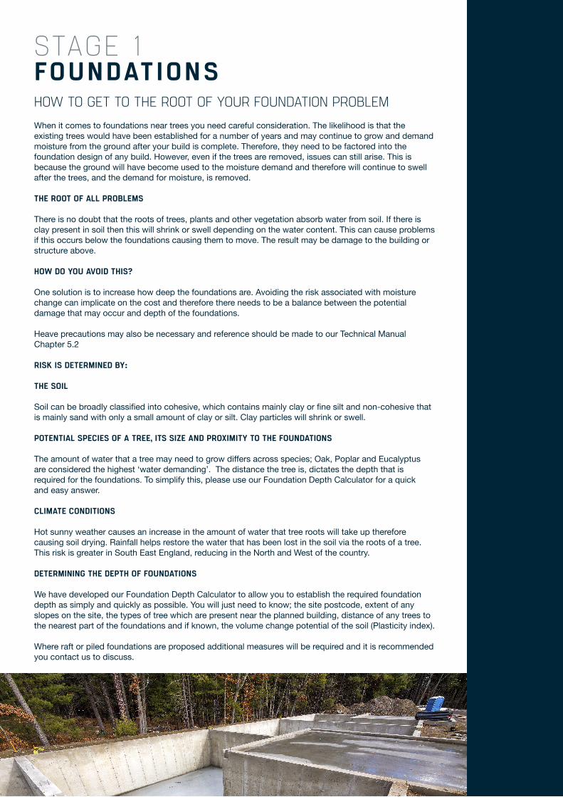
HOW TO GET TO THE ROOT OF YOUR FOUNDATION PROBLEMWhen it comes to foundations near trees you need careful consideration. The likelihood is that the existing trees would have been established for a number of years and may continue to grow and demand moisture from the ground after your build is complete. Therefore, they need to be factored into the foundation design of any build. However, even if the trees are removed, issues can still arise. This is because the ground will have become used to the moisture demand and therefore will continue to swell after the trees, and the demand for moisture, is removed.
THE ROOT OF ALL PROBLEMS
There is no doubt that the roots of trees, plants and other vegetation absorb water from soil. If there is clay present in soil then this will shrink or swell depending on the water content. This can cause problems if this occurs below the foundations causing them to move. The result may be damage to the building or structure above.
HOW DO YOU AVOID THIS?
One solution is to increase how deep the foundations are. Avoiding the risk associated with moisture change can implicate on the cost and therefore there needs to be a balance between the potential damage that may occur and depth of the foundations.
Heave precautions may also be necessary and reference should be made to our Technical Manual Chapter 5.2
RISK IS DETERMINED BY:
THE SOIL
Soil can be broadly classified into cohesive, which contains mainly clay or fine silt and non-cohesive that is mainly sand with only a small amount of clay or silt. Clay particles will shrink or swell.
POTENTIAL SPECIES OF A TREE, ITS SIZE AND PROXIMITY TO THE FOUNDATIONS
The amount of water that a tree may need to grow differs across species; Oak, Poplar and Eucalyptus are considered the highest ‘water demanding’. The distance the tree is, dictates the depth that is required for the foundations. To simplify this, please use our Foundation Depth Calculator for a quick and easy answer.
CLIMATE CONDITIONS
Hot sunny weather causes an increase in the amount of water that tree roots will take up therefore causing soil drying. Rainfall helps restore the water that has been lost in the soil via the roots of a tree. This risk is greater in South East England, reducing in the North and West of the country.
DETERMINING THE DEPTH OF FOUNDATIONS
We have developed our Foundation Depth Calculator to allow you to establish the required foundation depth as simply and quickly as possible. You will just need to know; the site postcode, extent of any slopes on the site, the types of tree which are present near the planned building, distance of any trees to the nearest part of the foundations and if known, the volume change potential of the soil (Plasticity index).
Where raft or piled foundations are proposed additional measures will be required and it is recommended you contact us to discuss.
FOUNDATIONSSTAGE 1
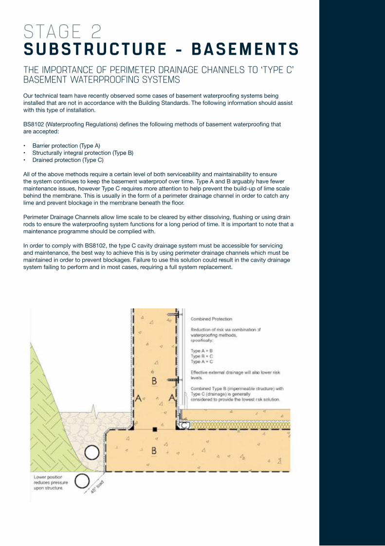
THE IMPORTANCE OF PERIMETER DRAINAGE CHANNELS TO ‘TYPE C’ BASEMENT WATERPROOFING SYSTEMSOur technical team have recently observed some cases of basement waterproofing systems being installed that are not in accordance with the Building Standards. The following information should assist with this type of installation.
BS8102 (Waterproofing Regulations) defines the following methods of basement waterproofing that are accepted:
• Barrier protection (Type A)• Structurally integral protection (Type B)• Drained protection (Type C)
All of the above methods require a certain level of both serviceability and maintainability to ensure the system continues to keep the basement waterproof over time. Type A and B arguably have fewer maintenance issues, however Type C requires more attention to help prevent the build-up of lime scale behind the membrane. This is usually in the form of a perimeter drainage channel in order to catch any lime and prevent blockage in the membrane beneath the floor.
Perimeter Drainage Channels allow lime scale to be cleared by either dissolving, flushing or using drain rods to ensure the waterproofing system functions for a long period of time. It is important to note that a maintenance programme should be complied with.
In order to comply with BS8102, the type C cavity drainage system must be accessible for servicing and maintenance, the best way to achieve this is by using perimeter drainage channels which must be maintained in order to prevent blockages. Failure to use this solution could result in the cavity drainage system failing to perform and in most cases, requiring a full system replacement.
SUBSTRUCTURE - BASEMENTSSTAGE 2
HOW TO AVOID THOSE UNWANTED CRACKSBuilding with masonry has been around for centuries with historic structures still standing today; such as the Egyptian pyramids, Roman amphitheatres and the Great Wall of China. It is no surprise masonry walls are still the most popular building structures used today with benefits like: durability, strength, temperature control, fire protection, noise barrier, ‘green’ material and large range of aesthetics. However, movement in these types of walls are common and provisions must be incorporated in the design to avoid the structure being compromised and unwanted cracking.
CAUSES OF MOVEMENT
After construction, buildings are subject to small dimensional changes, which can be caused by one or more of the following factors:
1) Change in temperature2) Change in moisture content3) Absorption of water vapour4) Chemical action, e.g. carbonation5) Deflection under loads6) Ground movement and differential settlement.
Masonry is not completely free to expand or contract because restraints are often present, and so compressive or tensile forces can develop and these can lead to bowing or cracking.
Movement characteristics of masonry units made of clay, calcium silicate, concrete and stone are likely to vary within each material type, due to differences in raw materials and/or manufacture, but movement characteristics differ more significantly between units of different types of material.
All materials expand and contract in response to thermal changes. In addition, clay materials undergo an irreversible expansion after their manufacture as moisture is absorbed from the atmosphere. Other masonry materials shrink following manufacture to reach the equilibrium state.
Units made from different types of material should not be bonded together in masonry in a manner that would cause stress to develop as a result of dissimilar characteristic movement. Where anticipated movements are different in magnitude and nature, parts of masonry of different material type should be effectively separated, e.g. by vertical or horizontal movement joints and/or slip planes. Alternatively, they should be suitably reinforced.
Generally, changes in temperature, moisture content or rate of drying-out due to the presence of insulation, do not need to be taken into account when considering movement in masonry. However, for brick masonry of certain clay bricks in applications where restraint is low (e.g. cladding) and high levels of solar heating are anticipated because of orientation, reduced spacing between movement joints is beneficial.
ACCOMMODATION FOR MOVEMENT IN MASONRY
i) Movement joints should be provided in the masonry to accommodate its expansion and/or contraction due to changes in temperature and the moisture characteristics of the masonry units. Joints should be built-in as work proceeds.
ii) Slip planes should be designed to allow parts of the construction to slide, one in relation to the other, thus reducing shear stresses in the adjacent materials. The design and positioning of movement joints and slip planes should be carefully considered, to ensure that in addition to accommodating movements, such joints or planes do not impair the stability of the wall or any of its functions.
iii) In external walls, movement joints and slip planes should be sealed, protected or otherwise designed to prevent water penetration.
vi) Fixings and services should not interfere with the performance of the joints or slip planes. Finishes should be discontinuous at movement joints and slip planes. Fixings and fittings should not tie across joints.
SUPERSTRUCTURE – EXTERNAL MASONRY WALLS
STAGE 3
HOW TO AVOID WATER DAMAGE WITH THE CORRECT DRAINAGE PROVISIONSZero fall flat roofs can be problematic, although some manufacturers suggest zero falls, reference should be made to BS 6229 which recommends a minimum finished fall of 1:80, this enables quick drainage and reduces the risk of ponding. Pitched roofs also need to be carefully considered, reference can be made to Regulation H3 of the Building Regulations and the associated guidance which provides details of how to calculate sizes of rainwater downpipes and gutters as well as other information to ensure good provision is made.
Good building and site drainage is essential and as stated more-so than ever, get it wrong and there can be short term and long term issues for both property occupier and other involved in property.
AT WHAT HEIGHT SHOULD AN ELECTRICAL FITTING BE INSTALLED?REQUIREMENTS: All wall mounted switches and socket outlets should be built-in at the required heights.
DETAILS:
In new dwellings only, switches and socket-outlets for lighting and other equipment should be between 450mm and 1200mm from finished floor level.
Consumer units should be mounted so that the switches are between 1350mm and 1450mm above floor level. At this height, the consumer unit is out of reach of young children yet accessible to other people when standing or sitting.
REQUIRED BY:
For switches and socket outlets, these are specified by Approved Document M which supports Part M of the Building Regulations (England and Wales).
Approved Document M does not recommend a height for new consumer units but the suggested measurements given in the details section will ensure you comply with Part M.
Additionally, door bells, entry phones, TV sockets and telephone jack points should be installed in accessible positions as indicated in the Approved Document M.
WHY?
To make them accessible for people whose reach is limited and to help facilitate independent living for all people with disabilities.
ROOFS
FIRST F IX AND SECOND FIXELECTRICAL F ITTINGS
STAGE 4
STAGE 5/6
ROOF TILING REGULATIONS : ARE YOU ON TOP OF THINGS?The BS 5534:2014 ‘Slating and tiling for pitched roofs and vertical cladding – Code of Practice’, supersedes BS 5534:2013
WHAT DOES THIS MEAN FOR NEW BUILDS?
FIXINGS OF ROOF COVERINGS:
The experience of recent weather patterns in the UK and Europe has resulted in changes to the theoretical wind loads used to calculate the mechanical fixing requirements of slates, roof tiles, ridge and hip tiles and roof systems. This means that roof tiles and fittings will under this new Code of Practice, require more mechanical fixings.
For example:
• All single lapped tiles on a roof now need to be mechanically fixed.• Tiles at the perimeter must now have a minimum of two fixings.
UNDERLAYS:
The new Standard introduces minimum performance requirements for roofing underlays, together with a new test method for determining the wind resistance of unsupported underlay.
The test will measure the upward deflection of an underlay and potential movement at its overlaps, when subjected to air pressures likely to be experienced in the UK. This is to ensure that an underlay cannot displace under a given wind load to the point where it makes contact with and displaces the roof tiles or slates.
A new labelling system is introduced to indicate where an underlay is suitable for different batten gauges.
MECHANICAL FIXING OF RIDGE AND HIP TILES:
In the new Standard, no reliance is placed on the strength of the mortar to hold the roof components in place, meaning ridge and hip tiles will be required to be mechanically fixed.
The industry has been moving towards mechanical fixing by installing dry ridge and hip systems as a standard practice. Mortar will still have its place with traditional and refurbishment projects; but they will need to be used in conjunction with mechanical fix options such as clips, nails or screws. Details and information on how to achieve this should be available from the roof tile manufacturers.
IN SUMMARY
The new Code of Practice became live on 1st September 2014. In doing so, a number of the major tile and underlay manufacturers have now produced guides to help understand the changes and help you choose the correct tiles, fixings and underlays for a given site location. To meet these new changes, all ridge and hip tiles must be mechanically fixed. Finally, all roofing underlay products having current third party product approvals (e.g. BBA, BRE or European Technical Approvals) will, from 1st March 2015 need to be checked to ensure they have been tested to the new standard when certifying underlays for their fitness for purpose.
SURFACE F IN ISHES - T IL INGSTAGE 7
LEVEL THRESHOLDS: A STEP BY STEP GUIDEBACKGROUND:
Whether to a house, flat, or bungalow, the threshold of an entrance to a dwelling should allow reasonable access for wheelchairs users and ambulant people to and from the building, allowing them to easily gain access to the building and use the building and its facilities.
Where the approach to the entrance consists of a level or ramped approach, an accessible threshold at the entrance should be provided.
The threshold design must seek to fulfil the following criteria:
• Minimising the risk of water or damp entering the building.• The provision of adequate sub-floor ventilation.• Requirements for the provision of soil / gas membranes.• Thermal insulation requirements to ensure there is no thermal bridging.• The provision of durable solutions, taking account of workmanship requirements.
DETAILS:
Accessible or level thresholds consist of three principal elements:
1. THE EXTERNAL LANDING AND ITS DRAINAGE
Objective: The external landing should be sufficiently large and level for ambulant disabled people and wheelchair users to be able to approach and if necessary turn to face the door. It should be designed to avoid standing water and limit the amount of surface water reaching the threshold.
External landings on a ramped approach should be laid to fall between 1:40 and 1:60 to provide surface water drainage, falling away from the doorway in a single direction. There should be no cross falls.
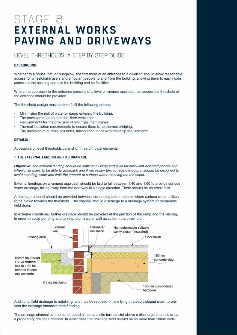
A drainage channel should be provided between the landing and threshold where surface water is likely to be blown towards the threshold. The channel should discharge to a drainage system or permeable field drain.
In extreme conditions, further drainage should be provided at the junction of the ramp and the landing, in order to avoid ponding and to keep storm water well away from the threshold.
EXTERNAL WORKS PAVING AND DRIVEWAYS
STAGE 8
Additional field drainage to adjoining land may be required on low lying or steeply sloped sites, to pre-vent the drainage channels from flooding.
The drainage channel can be constructed either as a site formed slot above a discharge channel, or by a proprietary drainage channel. In either case the drainage slots should be no more than 18mm wide.
In addition to specific guidance for the threshold design, consideration should be given to additional measures which would facilitate access to the building, e.g. A porch roof will provide considerable protection to ambulant disabled and wheel chair users whilst they locate keys, codes etc., at the same time as helping to reduce the risk of direct water entry.
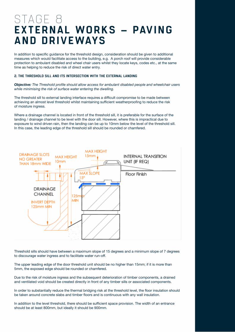
2. THE THRESHOLD SILL AND ITS INTERSECTION WITH THE EXTERNAL LANDING
Objective: The Threshold profile should allow access for ambulant disabled people and wheelchair users while minimising the risk of surface water entering the dwelling.
The threshold sill to external landing interface requires a difficult compromise to be made between achieving an almost level threshold whilst maintaining sufficient weatherproofing to reduce the risk of moisture ingress.
Where a drainage channel is located in front of the threshold sill, it is preferable for the surface of the landing / drainage channel to be level with the door sill. However, where this is impractical due to exposure to wind driven rain, then the landing can be up to 10mm below the level of the threshold sill. In this case, the leading edge of the threshold sill should be rounded or chamfered.
EXTERNAL WORKS – PAVING AND DRIVEWAYS
STAGE 8
Threshold sills should have between a maximum slope of 15 degrees and a minimum slope of 7 degrees to discourage water ingress and to facilitate water run-off.
The upper leading edge of the door threshold unit should be no higher than 15mm; if it is more than 5mm, the exposed edge should be rounded or chamfered.
Due to the risk of moisture ingress and the subsequent deterioration of timber components, a drained and ventilated void should be created directly in front of any timber sills or associated components.
In order to substantially reduce the thermal bridging risk at the threshold level, the floor insulation should be taken around concrete slabs and timber floors and is continuous with any wall insulation.
In addition to the level threshold, there should be sufficient space provision. The width of an entrance should be at least 800mm, but ideally it should be 900mm.
3. THE INTERSECTION BETWEEN THE DOOR THRESHOLD AND THE INTERNAL FLOOR FINISH.
Objective: The transition between the lower threshold unit and the internal floor level should accommodate accessible transfer for ambulant disabled people and wheelchair users, while permitting occupants the choice of varying the type and thickness of floor coverings.
The internal floor adjacent to the threshold should be level or gradually sloped by means of an internal transition unit in order to make it easier to get indoors.
There is no requirement for a graded platform or internal transition unit where the expected finished floor level is designed to be less than 15mm below the level of the door threshold unit. This clearance should be reduced to 10mm where the floor covering specified is an uncompressed soft pile carpet. Where a graded transition is specified this should have a maximum slope of 15 degrees and have a slip resistant surface.
There should be sufficient space within the internal lobby area to allow full turning for wheelchair users and unobstructed entry for other disabled users.
RECOMMENDATIONS:
Level thresholds are solely for their intended purpose. The principals adopted here should not be used to justify the positioning of external ground levels flush with internal ground floors.
Damp proof courses must be positioned at least 150mm above external ground level. The sole plates of timber framed houses must be at least 150mm above external ground level and be served by a drained and ventilated cavity. It is also recommended that raised Cavity trays or damp proof courses should be installed in external cavity walls in the vicinity of ramps.
REFERENCES:
• DETR - Accessible Thresholds in New Housing. Guidance for House builders and Designers.• BRE Good Building Guide 47: Level External Thresholds: Reducing moisture penetration and thermal bridging.• Building Regulations Approved Documents M.• The Building (Scotland) Regulations 2004 and supporting Technical Handbooks.
Thank you for reading our ebook, you can find more technical articles by visiting: http://www.premierguarantee.co.uk/blog/ For all other enquiries and information about our structural warranties and building control:
T 08444 120 888 E [email protected]
www.premierguarantee.co.uk

Premier Guarantee | 2 Shore Lines Building | Shore Road | Birkenhead | Wirral | CH41 1AU
T 08444 120 888 | F 08444 120 333 | E [email protected] | W www.premierguarantee.co.uk
MD Insurance Services Ltd is the Scheme Administrator for the Premier Guarantee range of structural warranties. MD Insurance Services Ltd is authorised and regulated by the Financial Conduct Authority.