54647 01 vsp_vs300_fh4_dcaj
TRANSCRIPT
Page 1 54647-01_97_B
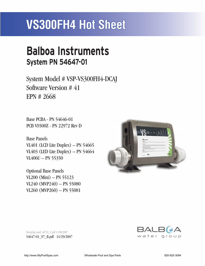
VS300FH4 Hot Sheet
54647-01_97_B.pdf 11/29/2007Template used: 40732_C.pdf 11/08/2007
System Model # VSP-VS300FH4-DCAJSoftware Version # 41EPN # 2668
Base PCBA - PN 54646-01PCB VS500Z - PN 22972 Rev D
Base PanelsVL401 (LCD Lite Duplex) – PN 54665VL403 (LED Lite Duplex) – PN 54664VL406U – PN 55350
Optional Base PanelsVL200 (Mini) – PN 55123VL240 (MVP240) – PN 55080VL260 (MVP260) – PN 55081
http://www.MyPoolSpas.com Wholesale Pool and Spa Parts 920-925-3094
Page 2 54647-01_97_B
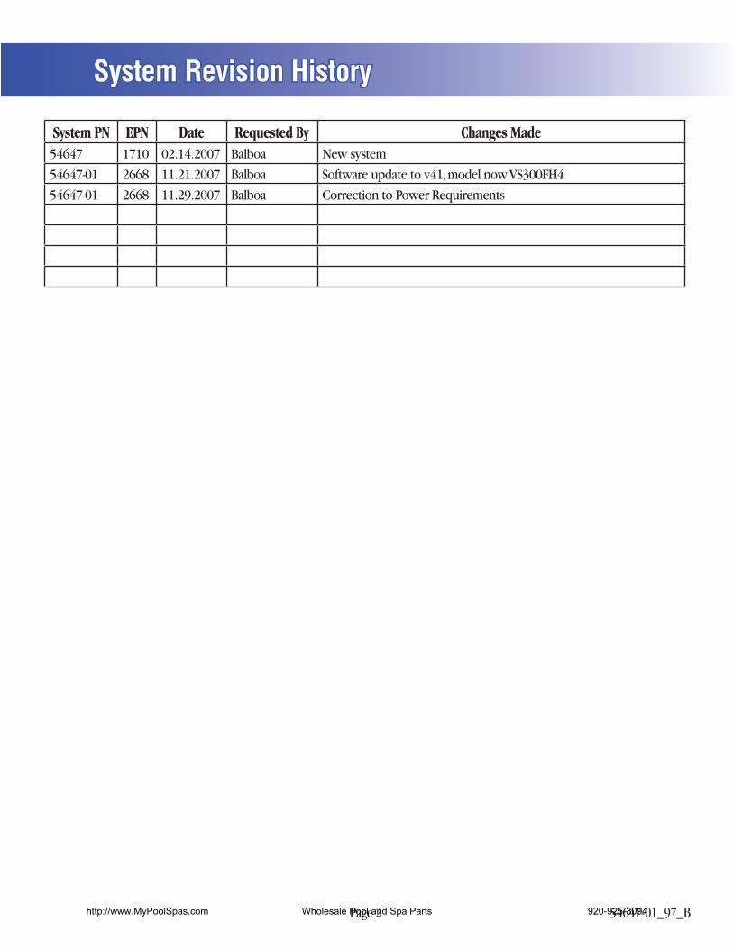
System Revision History
System PN EPN Date Requested By Changes Made54647 1710 02.14.2007 Balboa New system
54647-01 2668 11.21.2007 Balboa Software update to v41, model now VS300FH4
54647-01 2668 11.29.2007 Balboa Correction to Power Requirements
http://www.MyPoolSpas.com Wholesale Pool and Spa Parts 920-925-3094

Page 3 54647-01_97_B
Additional Options
Basic System Features and Functions
Setup 1 (As Manufactured)
Optional Panels
Power Requirements
System Outputs
http://www.MyPoolSpas.com Wholesale Pool and Spa Parts 920-925-3094

Page 4 54647-01_97_B
Basic System Features and Functions
Any time you change a DIP Switch, other than A1, you must reset Persistent Memory for your new DIP Switch Settings changes to take effect. If you do not reset Persistent Memory, your system may function improperly.
To reset Persistent Memory: Power down by disconnecting power source from spa. Put a jumper across J43, covering both pins. (See illustration below) Power up by connecting power source to spa. Wait until “ ” is displayed on your panel. Power down again. Remove jumper from J43 (May also move to cover 1 pin only) Power up again.
About Persistent Memory and Time of Day Retention:This system uses memory that doesn’t require a battery to store a variety of settings. What we refer to as Persistent Memory stores the filter settings, the set temperature, and the heat mode.
Persistent Memory is not used for Time of Day. Only models with a Serial Deluxe panel installed (VS5xxDZ and GS5xxDZ) can display the time. However, during power loss to the spa, the system will lose the correct time, and reset to 12:00 PM when power is restored.
Power Up Display SequenceUpon power up, you should see the following on the display:
Three numbers in a row, which are the SSID (the System Software ID). The third display of these numbers is the Software Version, which should match the version of your system. For example, if these three numbers are , that is a VS511SZ at version 38.
Displayed next is: “ ” (indicating the system is configured for a heater between 3 and 6 kW) or “ ” (indicating the system is configured for a heater effectively* between 1 and 3 kW). “ ” should appear for all VS models running at 240VAC. “ ” should appear for all VS models running at 120VAC, as well as all GS models. (*A heater which is rated at 4 kW at 240VAC will function as a 1 kW heater at 120VAC.)
“ ” will appear to signal the start of Priming Mode.
At this point, the power up sequence is complete. Refer to the Reference Card for the VS or GS System model of your spa for information about how the spa operates from this point on, including how to adjust the Time of Day if using a Serial Deluxe style panel.
GC
GC
GC
GC
CG
T1
SWITCHBANK A
BALBOA INSTRUMENTS, INC.VS500ZP/N 22972 REV D
MADE IN U.S.ACOPYRIGHT 2005
S1
J6 J7 J8J44J60 J22
U4
FUSE .3A 250V
FUSE 20A 250V
FUSE
3A
250V
E.GN
D
F4
K6 K1
K8K9
K5
J23 J46
J46
F1
J29J47J50 F7
J17/
26 J20
J1A
J10
J13
J2A
EXT.TTRLYLL
TST AUX. FSEN. A SEN. B
VACV
W1
W7
J1
J2
W2W3
GC
W4
K2K3
F2
J12
1 2 3
J43
2-SPDEXT RLY
J18
SWITCHBANK AS1
J6
E.GN
D
TST
J43
J43 on VS5xxZ and VS300 Series Main Board Shown.J43 on GS5xxZ Series is located in approximately the same position.
GC
SWITCHBANK A
P/N
2296
4_B
MAD
E IN
U.S.
A.VS
100
© 2
006
S1
K3
K5
K4 K1
PUMP
K2
J7 J8
U4
T0.25A 250VF2
J23
GC
OZONEJ29
HEATERAA
J9
J20
TST RST
SEN. A SEN. B
J1
Balbo
a F4
J43J6
G C
F5, F3A 250V
J26
J58 J57
J50
J50
J13
J13
J12
J12
J90
J90
LINE
NEUTRALNEUTRALWHT AC
BLK AC
W1
J18
SWITCHBANK A
TST RSTJ43J6
J43 on VS100/GS100 Series Main Board Shown.
http://www.MyPoolSpas.com Wholesale Pool and Spa Parts 920-925-3094
Page 5 54647-01_97_B
GC
GC
RED AC
WHT ACT
J32
T1
SWITCHBANK A
J11 J15 J25 J63
J33
BALBOA INSTRUMENTS, INC.VS500ZP/N 22972 REV D
MADE IN U.S.ACOPYRIGHT 2005
S1
J6 J7 J8
U4
HTR2 HTR1
TB1
FUSE .3A 250V
FUSE
3A
250V
E.GN
D
CLASS G FUSE 30A F5
F4
K6 K1
W10
K5
J23
J73 F1
J29
J20
TSTSEN. A SEN. B
W1
J1
W2
K4 K2K3
Balboa
F2
J43
J18TORQUE
RANGE FOR TB1:27-30 IN. LBS.
HOTBLACK
NEUTRALW
HITEHOTRED
GC
FUSE 3A 250V
Black jumper required.Do not remove.
4.0 kW4.0 kW Heater rated @ 240V(Approx. 1kW @ 120V)
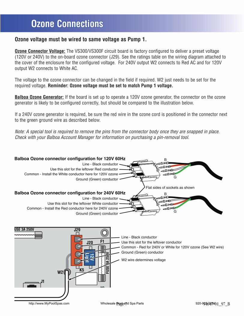
Ozone
Ozone must be same voltage as Pump 1.Ozone runs with Pump 1 low-speed.
12V Light
2-Spd P1
Wiring Configuration and DIP Settings
Setup 1 (As Manufactured)
A1, Test Mode OFFA2, Un, P1, TE, LT A7, Mode changes allowed
A10, High Amp modeA5, P1-high timeout, Table 1A4, N/A (must be OFF) A9, P1-low timeout, Table 1
Panel Button Assignments1=Unused2=Pump 1
3=Temp4=Light
Panel Button Positions
1 2 3 41
4 23
1005941
SSID #
MemoryReset
J43A2, P1, LT, TD, TUA2, P1, LT, TD, TU
1=Pump 12=Light
3=Temp Down4=Temp Up
120 Volt Connections
240 Volt Connections
Black AC Jumpers
12 Volt Connections
Relay Control Wires
Wiring Color Key
Typically Line voltage
Typically Line voltage for 2-speed pumps
Neutral (Common)
Ground
Note flat sides in connector
Board Connector Key
1
2
3
4
WARNING: Main Power to system should be turned OFF BEFORE adjusting DIP switches.WARNING: Persistent Memory (J43) must be RESET to allow new DIP switch settings to take effect. (See Persistent Memory page)
http://www.MyPoolSpas.com Wholesale Pool and Spa Parts 920-925-3094
Page 6 54647-01_97_B
DIP Switches and Jumpers Definitions
Jumper Key J43 When jumper is placed on 2 pins during power-up, system will reset persistent memory. Leave on 1 pin only to enable persistent memory feature.
DIP Switch Key A1 Test Mode (normally OFF) A2 “ON” position: Button layout will be: Pump 1, Light, Temp Down, Temp Up * “OFF” position: Button layout will be: Unused, Pump 1, Temp, Light A3 “ON” position: use Mini Panel * “OFF” position: use Lite Duplex or Digital Duplex panel A4 N/A (must be OFF) A5 Pump 1 high-speed timeout, see Table 1 A6 “ON” position: 50Hz operation “OFF” position: 60Hz operation A7 “ON” position: Standard mode only “OFF” position: Std/Ecn/Sleep mode changes allowed A8 “ON” position: temperature is displayed in degrees Celsius “OFF” position: temperature is displayed in degrees Fahrenheit A9 Pump 1 low-speed timeout, see Table 1 A10 “ON” position: heater is disabled while the high-speed pump is running (low amperage mode) “OFF” position: heater can run while the high-speed pump is running (high amperage mode)* Panels with button layout are not compatible when A2 or A3 is ON.Note: No blower or second pump available.
WARNING:Setting DIP switches incorrectly may cause abnormal system behavior and/or damage to system components.Refer to Switchbank illustration on Wiring Configuration page for correct settings for this system.Contact Balboa if you require additional configuration pages added to this hot sheet.
Base Model VS300F
A3: OFF
Panel Button Positions
Panel Button Assignments
A3:ON
A2: OFF
A2:ON
1
1 2 3 4
2 3 4
1
4 23
1=Unused2=Pump 1
3=Temp4=Light
1=Pump 12=Light
3=Temp Down4=Temp Up
SSID 100 59 41
Table 1 Pump 1 Timeouts
A5 A9 Low-spd Hi-spd
OFF OFF 2 hours 15 min ON OFF 2 hours 30 min OFF ON 15 min 15 min ON ON 30 min 30 min
http://www.MyPoolSpas.com Wholesale Pool and Spa Parts 920-925-3094
Page 7 54647-01_97_B
W
W
FUSE
3A
250V
K5
F1
J29
J20
J10
J1
W2
12V Light
USE 3A 250V
Use this slot for the leftover Red conductorLine - Black conductor
Balboa Ozone connector configuration for 120V 60Hz
Ground (Green) conductor
Flat sides of sockets as shown
Common - Install the White conductor here for 120V ozone
Use this slot for the leftover White conductorLine - Black conductor
Balboa Ozone connector configuration for 240V 60Hz
Ground (Green) conductorCommon - Install the Red conductor here for 240V ozone
B
G
B
G
Use this slot for the leftover conductorLine - Black conductor
Ground (Green) conductorCommon - Red for 240V or White for 120V ozone (See W2 wire)
W2 wire determines voltage
Ozone ConnectionsOzone voltage must be wired to same voltage as Pump 1.
Ozone Connector Voltage: The VS300/VS300F circuit board is factory configured to deliver a preset voltage (120V or 240V) to the on-board ozone connector (J29). See the ratings table on the wiring diagram attached to the cover of the enclosure for the configured voltage. For 240V output W2 connects to Red AC and for 120V output W2 connects to White AC.
The voltage to the ozone connector can be changed in the field if required. W2 just needs to be set for the required voltage. Reminder: Ozone voltage must be set to match Pump 1 voltage.
Balboa Ozone Generator: If the board is set up to operate a 120V ozone generator, the connector on the ozone generator is likely to be configured correctly, but should be compared to the illustration below.
If a 240V ozone generator is required, be sure the red wire in the ozone cord is positioned in the connector next to the green ground wire as described below.
Note: A special tool is required to remove the pins from the connector body once they are snapped in place. Check with your Balboa Account Manager for information on purchasing a pin-removal tool.
http://www.MyPoolSpas.com Wholesale Pool and Spa Parts 920-925-3094
Page 8 54647-01_97_B
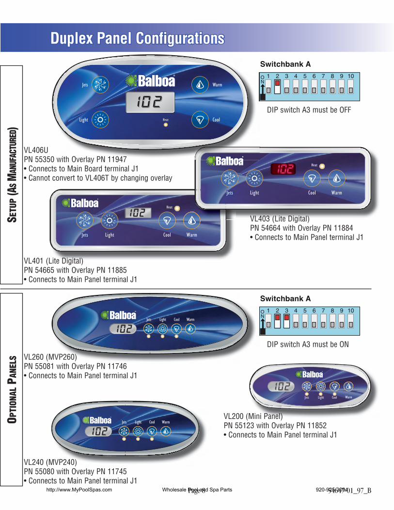
Duplex Panel Configurations
SETU
P (A
S MAN
UFAC
TURE
D)OP
TION
AL P
ANEL
S
VL240 (MVP240)PN 55080 with Overlay PN 11745 Connects to Main Panel terminal J1
WarmCoolJets Light
VL260 (MVP260)PN 55081 with Overlay PN 11746 Connects to Main Panel terminal J1
DIP switch A3 must be OFF
DIP switch A3 must be ON
Heat
JetsJets Light Cool Warm
VL401 (Lite Digital)PN 54665 with Overlay PN 11885 Connects to Main Panel terminal J1
Jets Light WarmCool
VL200 (Mini Panel)PN 55123 with Overlay PN 11852 Connects to Main Panel terminal J1
Heat
JetsJets Light Cool Warm
VL403 (Lite Digital)PN 54664 with Overlay PN 11884 Connects to Main Panel terminal J1
MVP240)
WarmCoolJets Light
Jets
Light
Warm
CoolHeat
VL406UPN 55350 with Overlay PN 11947 Connects to Main Board terminal J1 Cannot convert to VL406T by changing overlay
http://www.MyPoolSpas.com Wholesale Pool and Spa Parts 920-925-3094