50-49/650-49 - cla-val manuals/tm-50-49.pdf · 50-49/650-49. model 100s/2100s (full internal port)...
TRANSCRIPT

50-49/650-49
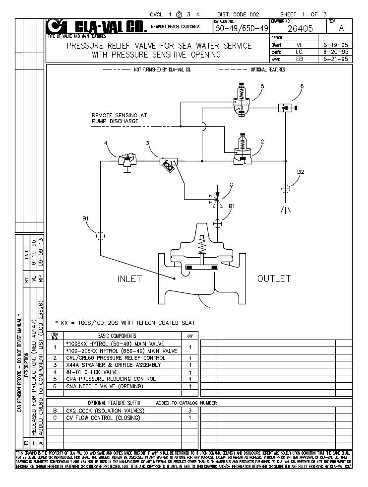


100S/2100SMODEL
(Full Internal Port)
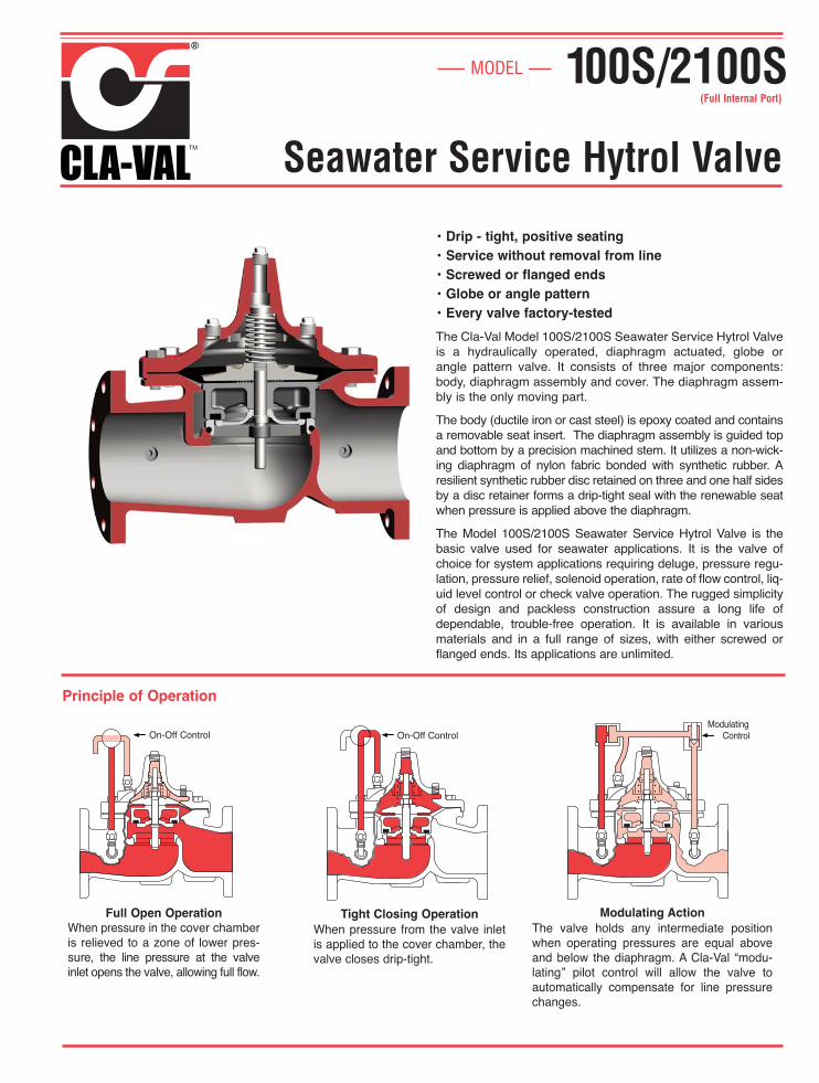
• Drip - tight, positive seating• Service without removal from line• Screwed or flanged ends• Globe or angle pattern• Every valve factory-tested
The Cla-Val Model 100S/2100S Seawater Service Hytrol Valveis a hydraulically operated, diaphragm actuated, globe orangle pattern valve. It consists of three major components:body, diaphragm assembly and cover. The diaphragm assem-bly is the only moving part.
The body (ductile iron or cast steel) is epoxy coated and containsa removable seat insert. The diaphragm assembly is guided topand bottom by a precision machined stem. It utilizes a non-wick-ing diaphragm of nylon fabric bonded with synthetic rubber. Aresilient synthetic rubber disc retained on three and one half sidesby a disc retainer forms a drip-tight seal with the renewable seatwhen pressure is applied above the diaphragm.
The Model 100S/2100S Seawater Service Hytrol Valve is thebasic valve used for seawater applications. It is the valve ofchoice for system applications requiring deluge, pressure regu-lation, pressure relief, solenoid operation, rate of flow control, liq-uid level control or check valve operation. The rugged simplicityof design and packless construction assure a long life ofdependable, trouble-free operation. It is available in variousmaterials and in a full range of sizes, with either screwed orflanged ends. Its applications are unlimited.
Modulating ActionThe valve holds any intermediate positionwhen operating pressures are equal aboveand below the diaphragm. A Cla-Val “modu-lating” pilot control will allow the valve toauto matically compensate for line pressurechanges.
Principle of Operation
Full Open OperationWhen pressure in the cover chamberis relieved to a zone of lower pres-sure, the line pressure at the valveinlet opens the valve, allowing full flow.
Tight Closing OperationWhen pressure from the valve inletis applied to the cover chamber, thevalve closes drip-tight.
On-Off ControlModulating
ControlOn-Off Control
Seawater Service Hytrol Valve
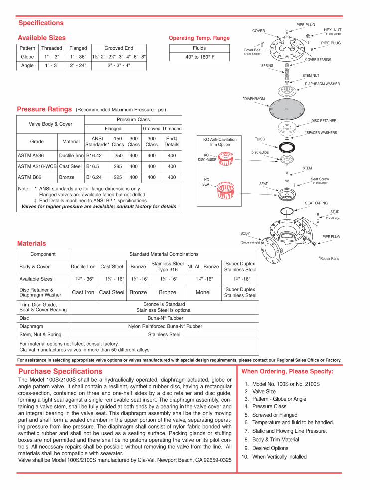
Specifications
When Ordering, Please Specify:
1. Model No. 100S or No. 2100S2. Valve Size3. Pattern - Globe or Angle4. Pressure Class
5. Screwed or Flanged6. Temperature and fluid to be handled.
7. Static and Flowing Line Pressure.
8. Body & Trim Material
9. Desired Options
10. When Vertically Installed
Purchase SpecificationsThe Model 100S/2100S shall be a hydraulically operated, diaphragm-actuated, globe orangle pattern valve. It shall contain a resilient, synthetic rubber disc, having a rectangularcross-section, contained on three and one-half sides by a disc retainer and disc guide,forming a tight seal against a single removable seat insert. The diaphragm assembly, con-taining a valve stem, shall be fully guided at both ends by a bearing in the valve cover andan integral bearing in the valve seat. This diaphragm assembly shall be the only movingpart and shall form a sealed chamber in the upper portion of the valve, separating operat-ing pressure from line pressure. The diaphragm shall consist of nylon fabric bonded withsynthetic rubber and shall not be used as a seating surface. Packing glands or stuffingboxes are not permitted and there shall be no pistons operating the valve or its pilot con-trols. All necessary repairs shall be possible without removing the valve from the line. Allmaterials shall be compatible with seawater.Valve shall be Model 100S/2100S manufactured by Cla-Val, Newport Beach, CA 92659-0325
For assistance in selecting appropriate valve options or valves manufactured with special design requirements, please contact our Regional Sales Office or Factory.
Available Sizes Operating Temp. Range
Fluids
-40° to 180° F
COVER
PIPE PLUG
COVER BEARING
SPRING
STEM NUT
DIAPHRAGM WASHER
DISC RETAINER
BODY
*SPACER WASHERS
DISC GUIDE
SEAT
PIPE PLUG
STEM
SEAT O-RING
STUD
8" and Larger
*DIAPHRAGM
*DISC
*Repair Parts
Seat Screw 8" and Larger
(Globe or Angle)
PIPE PLUG
HEX NUT 8" and Larger
Cover Bolt 6" and Smaller
KO DISC GUIDE
KO SEAT
KO Anti-Cavitation Trim Option
Component Standard Material Combinations
Body & Cover Ductile Iron Cast Steel BronzeStainless Steel
Type 316NI. AL. Bronze
Super DuplexStainless Steel
Available Sizes 11⁄4" - 36" 11⁄4" - 16" 11⁄4" -16" 11⁄4" -16" 11⁄4" -16" 11⁄4" -16"
Disc Retainer &Diaphragm Washer Cast Iron Cast Steel Bronze Bronze Monel Super Duplex
Stainless Steel
Trim: Disc Guide, Seat & Cover Bearing
Bronze is StandardStainless Steel is optional
Disc Buna-N® Rubber
Diaphragm Nylon Reinforced Buna-N® Rubber
Stem, Nut & Spring Stainless Steel
For material options not listed, consult factory.Cla-Val manufactures valves in more than 50 different alloys.
Materials
Pattern Threaded Flanged Grooved End
Globe 1" - 3" 1" - 36" 11⁄2"-2"- 21⁄2"- 3"- 4"- 6"- 8"
Angle 1" - 3" 2" - 24" 2" - 3" - 4"
Valve Body & CoverPressure Class
Flanged Grooved Threaded
Grade MaterialANSI
Standards*150
Class 300
Class300
ClassEnd‡
Details
ASTM A536 Ductile Iron B16.42 250 400 400 400
ASTM A216-WCB Cast Steel B16.5 285 400 400 400
ASTM B62 Bronze B16.24 225 400 400 400
Note: * ANSI standards are for flange dimensions only.Flanged valves are available faced but not drilled.
‡ End Details machined to ANSI B2.1 specifications.Valves for higher pressure are available; consult factory for details
Pressure Ratings (Recommended Maximum Pressure - psi)
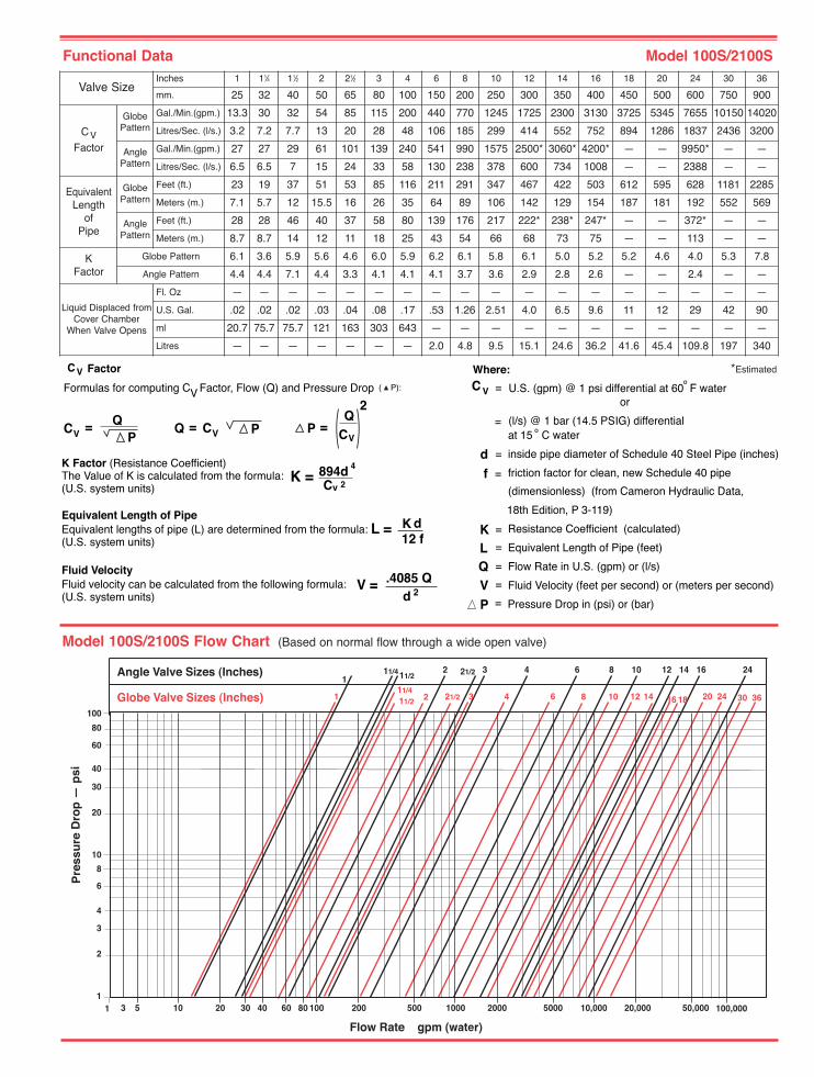
Model 100S/2100S Flow Chart (Based on normal flow through a wide open valve)
K = 894d 4
C 2v
L = K 12 f
K Factor (Resistance Coefficient)The Value of K is calculated from the formula:(U.S. system units)
Equivalent Length of PipeEquivalent lengths of pipe (L) are determined from the formula:(U.S. system units)
Fluid VelocityFluid velocity can be calculated from the following formula:(U.S. system units)
d
V = .4085 Q2d
CV Factor
Formulas for computing C Factor, Flow (Q) and Pressure Drop V ( P):
CV = QP
CV=Q P CV=
QP
2V
Where:
U.S. (gpm) @ 1 psi differential at 60 F water
(l/s) @ 1 bar (14.5 PSIG) differential
or
at 15 C water
inside pipe diameter of Schedule 40 Steel Pipe (inches)
friction factor for clean, new Schedule 40 pipe
(dimensionless) (from Cameron Hydraulic Data,
18th Edition, P 3-119)
Resistance Coefficient (calculated)
Equivalent Length of Pipe (feet)
Flow Rate in U.S. (gpm) or (l/s)
Fluid Velocity (feet per second) or (meters per second)
Pressure Drop in (psi) or (bar)
=
=
=
=
=
=
=
=
=PVQLK
fd
C
Functional Data Model 100S/2100S
*Estimated
1211/2
2 3 4 6 8 10 1621/2 14 2411/41
1 2 3 4 6 8 10 12 2421/211/214 16
11/436302018
10 20 30 40 60 80 100 200 500 1000 2000 5000 10,000 20,000 50,000 1
2
3
4
6
8
10
20
30
40
60
80
100
5 3
Angle Valve Sizes (Inches)
Globe Valve Sizes (Inches)
Pre
ssu
re D
rop
— p
si
Flow Rate gpm (water)
1 100,000
Valve SizeInches 1 11⁄4 11⁄2 2 21⁄2 3 4 6 8 10 12 14 16 18 20 24 30 36
mm. 25 32 40 50 65 80 100 150 200 250 300 350 400 450 500 600 750 900
CVFactor
GlobePattern
Gal./Min.(gpm.) 13.3 30 32 54 85 115 200 440 770 1245 1725 2300 3130 3725 5345 7655 10150 14020
Litres/Sec. (l/s.) 3.2 7.2 7.7 13 20 28 48 106 185 299 414 552 752 894 1286 1837 2436 3200
AnglePattern
Gal./Min.(gpm.) 27 27 29 61 101 139 240 541 990 1575 2500* 3060* 4200* — — 9950* — —
Litres/Sec. (l/s.) 6.5 6.5 7 15 24 33 58 130 238 378 600 734 1008 — — 2388 — —
EquivalentLength
ofPipe
GlobePattern
Feet (ft.) 23 19 37 51 53 85 116 211 291 347 467 422 503 612 595 628 1181 2285
Meters (m.) 7.1 5.7 12 15.5 16 26 35 64 89 106 142 129 154 187 181 192 552 569
AnglePattern
Feet (ft.) 28 28 46 40 37 58 80 139 176 217 222* 238* 247* — — 372* — —
Meters (m.) 8.7 8.7 14 12 11 18 25 43 54 66 68 73 75 — — 113 — —
K Factor
Globe Pattern 6.1 3.6 5.9 5.6 4.6 6.0 5.9 6.2 6.1 5.8 6.1 5.0 5.2 5.2 4.6 4.0 5.3 7.8
Angle Pattern 4.4 4.4 7.1 4.4 3.3 4.1 4.1 4.1 3.7 3.6 2.9 2.8 2.6 — — 2.4 — —
Liquid Displaced fromCover Chamber
When Valve Opens
Fl. Oz — — — — — — — — — — — — — — — — — —
U.S. Gal. .02 .02 .02 .03 .04 .08 .17 .53 1.26 2.51 4.0 6.5 9.6 11 12 29 42 90
ml 20.7 75.7 75.7 121 163 303 643 — — — — — — — — — — —
Litres — — — — — — — 2.0 4.8 9.5 15.1 24.6 36.2 41.6 45.4 109.8 197 340
CLA-VAL Copyright Cla-Val 2011 Printed in USA Specifications subject to change without notice. P.O. Box 1325 • Newport Beach, CA 92659-0325 • Phone: 949-722-4800 • Fax: 949-548-5441 • E-mail: [email protected] • Website cla-val.com
© E-100S/2100S (R-7/2011)
Cla-Val Control Valves operate with maximum efficiency when mounted in horizontal piping with the main valve cover UP, however, other positions are acceptable. Due tocomponent size and weight of 8 inch and larger valves, installation with cover UP is advisable. We recommend isolation valves be installed on inlet and outlet for maintenance.Adequate space above and around the valve for service personnel should be considered essential. A regular maintenance program should be established based on the specificapplication data. However, we recommend a thorough inspection be done at least once a year. Consult factory for specific recommendations.
GGG
GGGDInlet
DDDDD
FFF
100S/2100SThreaded &
Flanged
A
E
C(MAX)
K
J
H
Inlet Outlet
AAAAA
B (Diameter)
GGGG
DDDDInlet
AAAA
100S/2100SGrooved
EE
CC(MAX)
K
J
H
Inlet Outlet
B (Diameter)
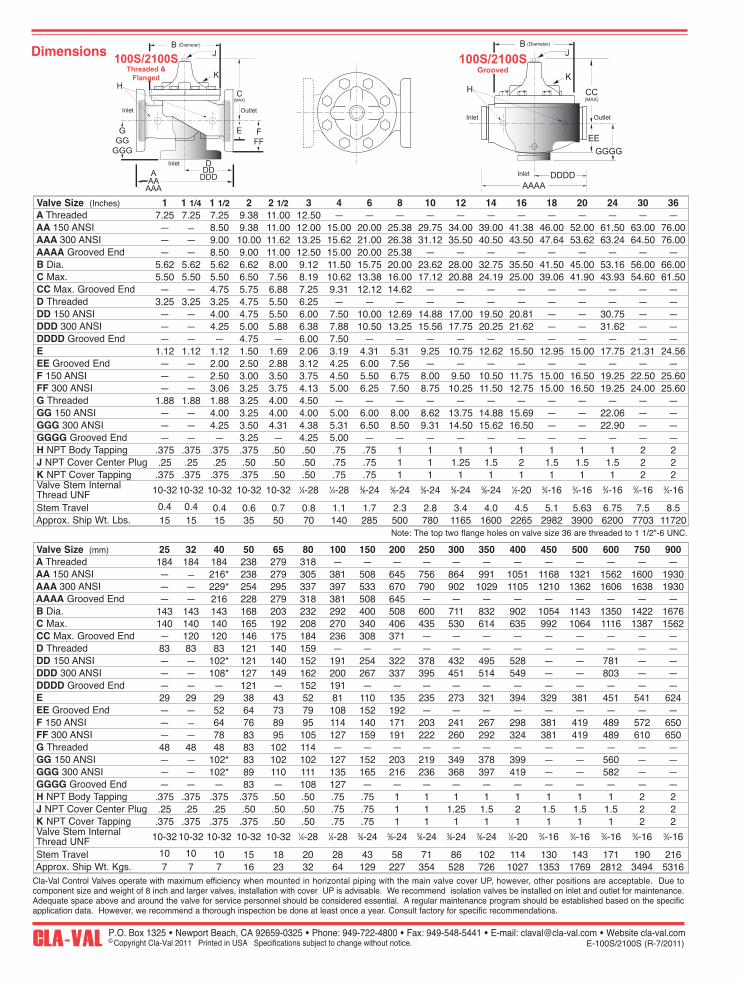
Note: The top two flange holes on valve size 36 are threaded to 1 1/2"-6 UNC.
Dimensions
Valve Size (Inches) 1 1 1/4 1 1/2 2 2 1/2 3 4 6 8 10 12 14 16 18 20 24 30 36A Threaded 7.25 7.25 7.25 9.38 11.00 12.50 — — — — — — — — — — — —AA 150 ANSI — — 8.50 9.38 11.00 12.00 15.00 20.00 25.38 29.75 34.00 39.00 41.38 46.00 52.00 61.50 63.00 76.00AAA 300 ANSI — — 9.00 10.00 11.62 13.25 15.62 21.00 26.38 31.12 35.50 40.50 43.50 47.64 53.62 63.24 64.50 76.00AAAA Grooved End — — 8.50 9.00 11.00 12.50 15.00 20.00 25.38 — — — — — — — — —B Dia. 5.62 5.62 5.62 6.62 8.00 9.12 11.50 15.75 20.00 23.62 28.00 32.75 35.50 41.50 45.00 53.16 56.00 66.00C Max. 5.50 5.50 5.50 6.50 7.56 8.19 10.62 13.38 16.00 17.12 20.88 24.19 25.00 39.06 41.90 43.93 54.60 61.50CC Max. Grooved End — — 4.75 5.75 6.88 7.25 9.31 12.12 14.62 — — — — — — — — —D Threaded 3.25 3.25 3.25 4.75 5.50 6.25 — — — — — — — — — — — —DD 150 ANSI — — 4.00 4.75 5.50 6.00 7.50 10.00 12.69 14.88 17.00 19.50 20.81 — — 30.75 — —DDD 300 ANSI — — 4.25 5.00 5.88 6.38 7.88 10.50 13.25 15.56 17.75 20.25 21.62 — — 31.62 — —DDDD Grooved End — — — 4.75 — 6.00 7.50 — — — — — — — — — — —E 1.12 1.12 1.12 1.50 1.69 2.06 3.19 4.31 5.31 9.25 10.75 12.62 15.50 12.95 15.00 17.75 21.31 24.56EE Grooved End — — 2.00 2.50 2.88 3.12 4.25 6.00 7.56 — — — — — — — — —F 150 ANSI — — 2.50 3.00 3.50 3.75 4.50 5.50 6.75 8.00 9.50 10.50 11.75 15.00 16.50 19.25 22.50 25.60FF 300 ANSI — — 3.06 3.25 3.75 4.13 5.00 6.25 7.50 8.75 10.25 11.50 12.75 15.00 16.50 19.25 24.00 25.60G Threaded 1.88 1.88 1.88 3.25 4.00 4.50 — — — — — — — — — — — —GG 150 ANSI — — 4.00 3.25 4.00 4.00 5.00 6.00 8.00 8.62 13.75 14.88 15.69 — — 22.06 — —GGG 300 ANSI — — 4.25 3.50 4.31 4.38 5.31 6.50 8.50 9.31 14.50 15.62 16.50 — — 22.90 — —GGGG Grooved End — — — 3.25 — 4.25 5.00 — — — — — — — — — — —H NPT Body Tapping .375 .375 .375 .375 .50 .50 .75 .75 1 1 1 1 1 1 1 1 2 2J NPT Cover Center Plug .25 .25 .25 .50 .50 .50 .75 .75 1 1 1.25 1.5 2 1.5 1.5 1.5 2 2K NPT Cover Tapping .375 .375 .375 .375 .50 .50 .75 .75 1 1 1 1 1 1 1 1 2 2Valve Stem InternalThread UNF 10-32 10-32 10-32 10-32 10-32 1⁄4-28 1⁄4-28 3⁄8-24 3⁄8-24 3⁄8-24 3⁄8-24 3⁄8-24 1⁄2-20 3⁄4-16 3⁄4-16 3⁄4-16 3⁄4-16 3⁄4-16
Stem Travel 0.4 0.4 0.4 0.6 0.7 0.8 1.1 1.7 2.3 2.8 3.4 4.0 4.5 5.1 5.63 6.75 7.5 8.5Approx. Ship Wt. Lbs. 15 15 15 35 50 70 140 285 500 780 1165 1600 2265 2982 3900 6200 7703 11720
Valve Size (mm) 25 32 40 50 65 80 100 150 200 250 300 350 400 450 500 600 750 900A Threaded 184 184 184 238 279 318 — — — — — — — — — — — —AA 150 ANSI — — 216* 238 279 305 381 508 645 756 864 991 1051 1168 1321 1562 1600 1930AAA 300 ANSI — — 229* 254 295 337 397 533 670 790 902 1029 1105 1210 1362 1606 1638 1930AAAA Grooved End — — 216 228 279 318 381 508 645 — — — — — — — — —B Dia. 143 143 143 168 203 232 292 400 508 600 711 832 902 1054 1143 1350 1422 1676C Max. 140 140 140 165 192 208 270 340 406 435 530 614 635 992 1064 1116 1387 1562CC Max. Grooved End — 120 120 146 175 184 236 308 371 — — — — — — — — —D Threaded 83 83 83 121 140 159 — — — — — — — — — — — —DD 150 ANSI — — 102* 121 140 152 191 254 322 378 432 495 528 — — 781 — —DDD 300 ANSI — — 108* 127 149 162 200 267 337 395 451 514 549 — — 803 — —DDDD Grooved End — — — 121 — 152 191 — — — — — — — — — — —E 29 29 29 38 43 52 81 110 135 235 273 321 394 329 381 451 541 624EE Grooved End — — 52 64 73 79 108 152 192 — — — — — — — — —F 150 ANSI — — 64 76 89 95 114 140 171 203 241 267 298 381 419 489 572 650FF 300 ANSI — — 78 83 95 105 127 159 191 222 260 292 324 381 419 489 610 650G Threaded 48 48 48 83 102 114 — — — — — — — — — — — —GG 150 ANSI — — 102* 83 102 102 127 152 203 219 349 378 399 — — 560 — —GGG 300 ANSI — — 102* 89 110 111 135 165 216 236 368 397 419 — — 582 — —GGGG Grooved End — — — 83 — 108 127 — — — — — — — — — — —H NPT Body Tapping .375 .375 .375 .375 .50 .50 .75 .75 1 1 1 1 1 1 1 1 2 2J NPT Cover Center Plug .25 .25 .25 .50 .50 .50 .75 .75 1 1 1.25 1.5 2 1.5 1.5 1.5 2 2K NPT Cover Tapping .375 .375 .375 .375 .50 .50 .75 .75 1 1 1 1 1 1 1 1 2 2Valve Stem InternalThread UNF 10-32 10-32 10-32 10-32 10-32 1⁄4-28 1⁄4-28 3⁄8-24 3⁄8-24 3⁄8-24 3⁄8-24 3⁄8-24 1⁄2-20 3⁄4-16 3⁄4-16 3⁄4-16 3⁄4-16 3⁄4-16
Stem Travel 10 10 10 15 18 20 28 43 58 71 86 102 114 130 143 171 190 216Approx. Ship Wt. Kgs. 7 7 7 16 23 32 64 129 227 354 528 726 1027 1353 1769 2812 3494 5316
DESCRIPTIONThe CRL Pressure Relief Control is a direct acting, spring loaded,diaphragm type relief valve. It may be used as a self-contained valve oras a pilot control for a Cla-Val Main valve. It opens and closes withinvery close pressure limits.INSTALLATIONThe CRL Pressure Relief Control may be installed in any position. Thecontrol body (7) has one inlet and one outlet port with a side pipe plug(24) at each port. These plugs are used for control connections or gaugeapplications. The inlet in the power unit body (6) is the sensing line port.A flow arrow is marked on the body casting.OPERATIONThe CRL Pressure Relief Control is normally held closed by the force ofthe compression spring above the diaphragm; control pressure is appliedunder the diaphragm.
When the controlling pressure exceeds the spring setting, the disc is liftedoff its seat, permitting flow through the control.
When controlling pressure drops below spring setting, the spring returnsthe control to its normally closed position.
ADJUSTMENT PROCEDUREThe CRL Pressure Relief Control can be adjusted to provide a relief set-ting at any point within the range found on the nameplate.
Pressure adjustment is made by turning the adjustment screw (9) to varythe spring pressure on the diaphragm. Turning the adjustment screwclockwise increases the pressure required to open the valve.Counterclockwise decreases the pressure required to open the valve.
When pressure adjustments are complete the jam nut (10) should betightened and the protective cap (1) replaced. If there is a problem oftampering, lock wire holes have been provided in cap and cover. Wirethe cap to cover and secure with lead seal.
DISASSEMBLYThe CRL Pressure Relief Control does not need to be removed from theline for disassembly. Make sure that pressure shut down is accompaniedprior to disassembly. If the CRL is removed from the line for disassemblybe sure to use a soft jawed vise to hold body during work.
Refer to Parts List Drawing for Item Numbers.1. Remove cap (1), loosen jam nut (10) and turn adjusting
screw counterclockwise until spring tension is relieved.2. Remove the eight screws (4) holding the cover (3) and
powerunit body (6). Hold the cover and powerunit together and place on a suitable work surface. See NOTE under REASSEMBLY.
3. Remove the cover (3) from powerunit body (6). The spring (12) and two spring guides (11).
4. Remove nut (13) from stem (19) and slide off the belleville washer (14), the upper diaphragm washer (15) and the diaphragm (16).
5. Pull the stem (19) with the disc retainer assembly (21) through the bottom of powerunit. The lower diaphragm washer (17) will slide off of stem top.
6. Remove jam nut (23) and disc retainer assembly (21) from stem. Use soft jawed pliers or vise to hold stem. The polished surface of stem must not be scored or scratched.
7. The seat (22) need not be removed unless it is damaged. If removal is necessary use proper size socket wrench and turn counterclockwise.Note: Some models have an integral seat in the body (7).
INSPECTIONInspect all parts for damage, or evidence of cross threading. Checkdiaphragm and disc retainer assembly for tears, abrasions or other dam-age. Check all metal parts for damage, corrosion or excessive wear.REPAIR AND REPLACEMENTMinor nicks and scratches may be polished out using 400 grit wet or drysandpaper fine emery or crocus cloth. Replace all O-rings and any dam-aged parts.When ordering replacement parts, be sure to specify parts list item num-ber and all nameplate data.REASSEMBLYIn general, reassembly is the reverse of disassembly. However, the fol-lowing steps should be observed:
1. Lubricate the O-Ring (18) with a small amount of a good grade of waterproof grease, (Dow Corning 44 medium grade or equal). Use grease sparingly and install O-ring in powerunit body (6).
2. Install stem (19) in powerunit body (6). Use a rotating motion with minimum pressure to let stem pass through O-ring.
Do Not Cut O-Ring.
3. Install O-ring (5) at top of stem (19). Place lower diaphragm washer (17) on the stem with the serrated side up. Position diaphragm (16), upper diaphragm washer (15), with serration down, and belleville washer (14) with concave side down.
4. Position powerunit body (6) as shown on parts list drawing (top view).
5. Continue reassembly as outlined in disassembly steps 1 through 3.
Pressure Relief ControlCRL
Note: Item (4) Screw will have a quantity of 8 for the 0-75 and 20-200psidesign and a quantity of 4 for the 100-300psi design. Item (25) Screw isused on the 100-300psi design only. Install item (25), before item (4) forpreload of item (12) spring.
SYMPTOM PROBABLE CAUSE REMEDY
Fails to open. Controlling pressuretoo low.
Back off adjustingscrew until valveopens.
Fails to open withspring compressionremoved.
Mechanical obstruc-tion, corrosion, scalebuild-up on stem.
Disassemble,locate,and removeobstruction, scale.
Leakage from covervent hole when con-trolling pressure isapplied.
Diaphragm Damage Disassembly replacedamageddiaphragm.
Fails to close withspring compressed.
Mechanical obstruc-tion.
Disassemble, locateand removeobstruction.
Fails to close. No spring compres-sion.
Re-set pressureadjustment.
Loose diaphragmassembly.
Tighten upperdiaphragm washer.
MODEL
INSTALLATION / OPERATION / MAINTENANCE
CLA-VAL Copyright Cla-Val 2011 Printed in USA Specifications subject to change without notice. P.O. Box 1325 • Newport Beach, CA 92659-0325 • Phone: 949-722-4800 • Fax: 949-548-5441 • E-mail: [email protected] • Website cla-val.com
© N-CRL (R-3/2011)
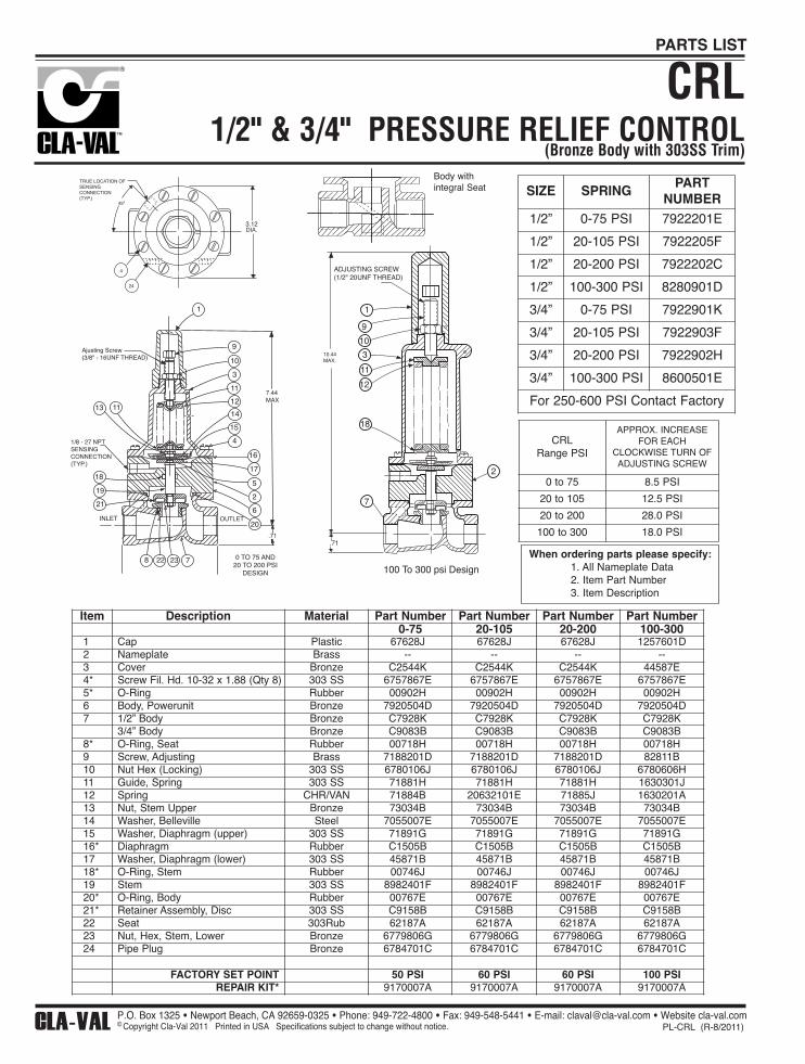
1/2" & 3/4" PRESSURE RELIEF CONTROL(Bronze Body with 303SS Trim)
CRL
Ajusting Screw(3/8" - 16UNF THREAD)
9
1
10
3
11
12
1413 11
8 22 23 7
18
19
21
INLET
1/8 - 27 NPTSENSINGCONNECTION(TYP.)
7.44MAX
.71
OUTLET20
6
2
0 TO 75 AND20 TO 200 PSI
DESIGN
5
17
16
15
4
1
9
10
3
11
12
18
7
2
100 To 300 psi Design
.71
ADJUSTING SCREW (1/2" 20UNF THREAD)
10.44 MAX.
When ordering parts please specify:1. All Nameplate Data 2. Item Part Number3. Item Description
24
4
45º
3.12 DIA.
TRUE LOCATION OF SENSING CONNECTION (TYP.)
Body withintegral Seat
CLA-VAL Copyright Cla-Val 2011 Printed in USA Specifications subject to change without notice. P.O. Box 1325 • Newport Beach, CA 92659-0325 • Phone: 949-722-4800 • Fax: 949-548-5441 • E-mail: [email protected] • Website cla-val.com
© PL-CRL (R-8/2011)
PARTS LIST
Item Description Material Part Number Part Number Part Number Part Number0-75 20-105 20-200 100-300
1 Cap Plastic 67628J 67628J 67628J 1257601D2 Nameplate Brass -- -- -- --3 Cover Bronze C2544K C2544K C2544K 44587E4* Screw Fil. Hd. 10-32 x 1.88 (Qty 8) 303 SS 6757867E 6757867E 6757867E 6757867E5* O-Ring Rubber 00902H 00902H 00902H 00902H6 Body, Powerunit Bronze 7920504D 7920504D 7920504D 7920504D7 1/2” Body Bronze C7928K C7928K C7928K C7928K
3/4” Body Bronze C9083B C9083B C9083B C9083B8* O-Ring, Seat Rubber 00718H 00718H 00718H 00718H9 Screw, Adjusting Brass 7188201D 7188201D 7188201D 82811B10 Nut Hex (Locking) 303 SS 6780106J 6780106J 6780106J 6780606H11 Guide, Spring 303 SS 71881H 71881H 71881H 1630301J12 Spring CHR/VAN 71884B 20632101E 71885J 1630201A13 Nut, Stem Upper Bronze 73034B 73034B 73034B 73034B14 Washer, Belleville Steel 7055007E 7055007E 7055007E 7055007E15 Washer, Diaphragm (upper) 303 SS 71891G 71891G 71891G 71891G16* Diaphragm Rubber C1505B C1505B C1505B C1505B17 Washer, Diaphragm (lower) 303 SS 45871B 45871B 45871B 45871B18* O-Ring, Stem Rubber 00746J 00746J 00746J 00746J19 Stem 303 SS 8982401F 8982401F 8982401F 8982401F20* O-Ring, Body Rubber 00767E 00767E 00767E 00767E21* Retainer Assembly, Disc 303 SS C9158B C9158B C9158B C9158B22 Seat 303Rub 62187A 62187A 62187A 62187A23 Nut, Hex, Stem, Lower Bronze 6779806G 6779806G 6779806G 6779806G24 Pipe Plug Bronze 6784701C 6784701C 6784701C 6784701C
FACTORY SET POINT 50 PSI 60 PSI 60 PSI 100 PSIREPAIR KIT* 9170007A 9170007A 9170007A 9170007A
CRLRange PSI
APPROX. INCREASEFOR EACH
CLOCKWISE TURN OF ADJUSTING SCREW
0 to 75 8.5 PSI
20 to 105 12.5 PSI
20 to 200 28.0 PSI
100 to 300 18.0 PSI
SIZE SPRINGPART
NUMBER1/2” 0-75 PSI 7922201E
1/2” 20-105 PSI 7922205F
1/2” 20-200 PSI 7922202C
1/2” 100-300 PSI 8280901D
3/4” 0-75 PSI 7922901K
3/4” 20-105 PSI 7922903F
3/4” 20-200 PSI 7922902H
3/4” 100-300 PSI 8600501E
For 250-600 PSI Contact Factory

When ordering parts, please specify:
• All Nameplate Data• Item Number • Description• Recommended Spare Parts
Strainer and Orifice Assembly
X44A
BRONZE BODY — DELRIN ORIFICE
1/8 NPT 3/8 NPT
3/4
3/4
3 3/8
2 3 5
43/8 NPT
8
7
61
2 1/4 MAX.
7/8
Inlet Outlet
X44A
STOCK NO.
71310-01F
-02
-03B
-04K
-05G
-06
* -07C
-08
-09
-10
-11
ORIFICE DIA.
.031
.046
.062
.078
.093
.109
.125
.140
.156
.187
.172
ORIFICE PLUG
PART # (ITEM 5)
94132-01
-02E
-03C
-04A
-05H
-06
-07D
-08
-09
-10H
-11F
*Standard
3/8" x 3/8"
ITEM
1
2
3
4
5
6
7
8
DESCRIPTION
Body
Plug, Top
"O" Ring, Plug Top
Screen
Orifice Plug
Plug, Pipe
Strainer Plug
"O" Ring, Strainer Plug
MATERIAL
Red Brs.
Brass
Syn. Rub.
Monel
Delrin
Brass
S.S.
Syn. Rub.
QTY.
1
1
1
1
1
1
1
1
CLA-VAL Copyright Cla-Val 2011 Printed in USA Specifications subject to change without notice. P.O. Box 1325 • Newport Beach, CA 92659-0325 • Phone: 949-722-4800 • Fax: 949-548-5441 • E-mail: [email protected] • Website cla-val.com
© PL-x44a (R-3/2011)
PARTS LIST
A2.50
A
2.75
SECTION AA
3/8 N.P.T.
1.25
1.50
3/8 N.P.T.BOTH ENDS
6
5
4
1
3
2
8
7
Outlet Inlet
Flow
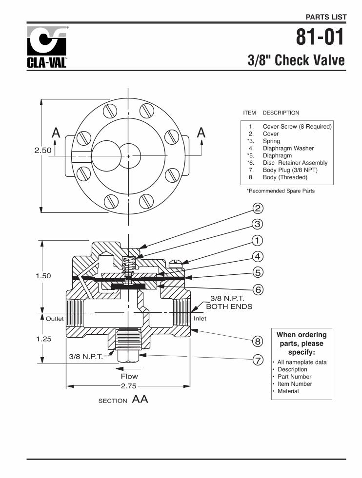
1. Cover Screw (8 Required)2. Cover
*3. Spring4. Diaphragm Washer
*5. Diaphragm*6. Disc Retainer Assembly7. Body Plug (3/8 NPT)8. Body (Threaded)
ITEM DESCRIPTION
When orderingparts, please
specify:• All nameplate data • Description• Part Number• Item Number• Material
*Recommended Spare Parts
3/8" Check Valve81-01
PARTS LIST
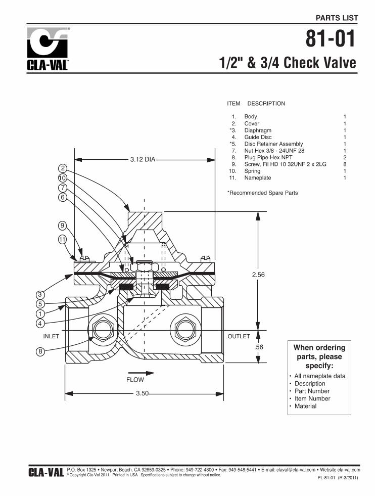
2
107
6
9
11
3
5
1
4
8
3.50
.56
2.56
FLOW
OUTLETINLET
3.12 DIA
ITEM DESCRIPTION
When orderingparts, please
specify:• All nameplate data • Description• Part Number• Item Number• Material
*Recommended Spare Parts
1/2" & 3/4 Check Valve81-01
CLA-VAL Copyright Cla-Val 2011 Printed in USA Specifications subject to change without notice. P.O. Box 1325 • Newport Beach, CA 92659-0325 • Phone: 949-722-4800 • Fax: 949-548-5441 • E-mail: [email protected] • Website cla-val.com
©PL-81-01 (R-3/2011)
PARTS LIST
1. Body 12. Cover 1
*3. Diaphragm 14. Guide Disc 1
*5. Disc Retainer Assembly 17. Nut Hex 3/8 - 24UNF 28 18. Plug Pipe Hex NPT 29. Screw, Fil HD 10 32UNF 2 x 2LG 8
10. Spring 111. Nameplate 1
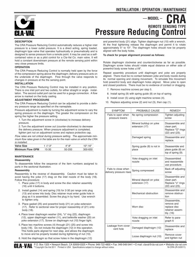
DESCRIPTIONThe CRA Pressure Reducing Control automatically reduces a higher inletpressure to a lower outlet pressure. It is a direct acting, spring loaded,diaphragm type valve that operates hydraulically or pneumatically and isdesigned to sense pressure from a remote point. It may be used as a self-contained valve or as a pilot control for a Cla-Val Co. main valve. It willhold a constant downstream pressure at the remote sensing point withinvery close pressure limits.OPERATIONThe CRA Pressure Reducing Control is normally held open by the forceof the compression spring above the diaphragm; delivery pressure acts onthe underside of the diaphragm. Flow through the valve responds tochanges in pressure at the the sensing point.INSTALLATIONThe CRA Pressure Reducing Control may be installed in any position.There is one inlet port and two outlets, for either straight or angle instal-lation. The second outlet port can be used for a gauge connection. A flowarrow is marked on the body casting.ADJUSTMENT PROCEDUREThe CRA Pressure Reducing Control can be adjusted to provide a deliv-ery pressure range as specified on the nameplate.Pressure adjustment is made by turning the adjustment screw to vary thespring pressure on the diaphragm. The greater the compression on thespring the higher the pressure setting.
1. Turn the adjustment screw in (clockwise) to increase delivery pressure.2. Turn the adjustment screw out (counter-clockwise) to decrease the delivery pressure. When pressure adjustment is completed, tighten jam nut on adjustment screw and replace protective cap.
Flow rates are not critical during pressure setting. The approximate min-imum flow rates given in the table are for the main valve on which the CRAis installed.Valve Size 1 1⁄4"-3" 4"-8" 10"-16"Minimum Flow GPM 15-30 50-200 300-650
MAINTENANCEDisassemblyTo disassemble follow the sequence of the item numbers assigned toparts in the sectional illustration.ReassemblyReassembly is the reverse of disassembly. Caution must be taken toavoid having the yoke (17) drag on the inlet nozzle of the body (18).Follow this procedure:
1. Place yoke (17) in body and screw the disc retainer assembly (16) until it bottoms.
2. Install gasket (14) and spring (19) for 2-30 psi range onto plug (13) and screw into body. Disc retainer must enter guide hole in plug as it is assembled. Screw the plug in by hand. Use wrench to tighten only.
3. Place gasket (25) and powertrol body (21) on yoke extension (17). Refer to sectional view for proper reassembly of (21) onto body (18).
4. Place lower diaphragm washer (24), "o" ring (22), diaphragm (12), upper diaphragm washer (11), and belleville washer (20) on yoke extension (17). Screw on diaphragm nut (10) finger tight.
5. Place two machine screws (4) through (21) (25) and screw into body (18). Do not include the diaphragm (12) in this operation. This holds parts aligned for next step, and allows the diaphragm to move and be properly located during tightening of nut (10).
6. Hold the diaphragm so that screw holes in the diaphragm (12)
SYMPTOM PROBABLE CAUSE REMEDY
Fails to open whenpressure lowers
No spring compression Tighten adjustingscrew
Mineral buildup on yokeextension (17)
Disassemble andclean part,Replace "O" rings(22) and (23).
Damaged spring Disassemble andreplace.
Spring guide (8) is not inplace
Disassemble andplace guide (8) ontop of spring (9).
Yoke dragging on inletnozzle
Disassembledand reassembleuse procedure.
Fails to close whendelivery pressure rises
Spring compressedBack off adjustingscrew
Mineral deposit on yokeextension (17)
Disassemble andclean part.Replace "o" rings(22) and (23).
Mechanical obstructionDisassemble andremove obstruc-tion
Worn disc
Disassemble,remove andreplace discretainer assem-bly. (16)
Yoke dragging on inletnozzle
Refer to para-graph 6
Damaged diaphragm (12)Disassemble andreplace
Loose diaphragm nut (10)Remove coverand tighten nut
REMOTE SENSING TYPECRA
Leakage from covervent hole
MODEL
INSTALLATION / OPERATION / MAINTENANCE
CLA-VAL Copyright Cla-Val 2011 Printed in USA Specifications subject to change without notice. P.O. Box 1325 • Newport Beach, CA 92659-0325 • Phone: 949-722-4800 • Fax: 949-548-5441 • E-mail: [email protected] • Website cla-val.com
© N-CRA (R-3/2011)
and powertrol body (21) align. Tighten diaphragm nut (10) with a wrench.At the final tightening release the diaphragm and permit it to rotateapproximately 5° to 10°. The diaphragm holes should now be properlyaligned with the body holes.
To check for proper alignment proceed as follows:
Rotate diaphragm clockwise and counterclockwise as far as possible.Diaphragm screw holes should rotate equal distance on either side ofpowertrol body screw holes ±1/8".
Repeat assembly procedure until diaphragm and yoke are properlyaligned. There must be no contact between yoke and body nozzle duringits normal opening and closing movement. To simulate this movementhold powertrol body and diaphragm holes aligned. Move yoke to openand closed positions. There must be no evidence of contact or dragging.
7. Remove machine screws per step 5.
8. Install spring (9) with spring guide (8) on top of spring.
9. Install cover (5) using eight machine screws (4).
10. Replace adjusting screw (2) and nut (3), then cap (1).
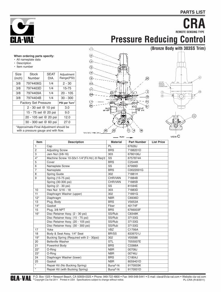
Pressure Reducing Control
REMOTE SENSING TYPE
4
15
6
7
1/8" NPTREMOTESENSINGCONNECTION
VIEW C
16
CRA
When ordering parts specify:• All nameplate data• Description• Item number
CLA-VAL Copyright Cla-Val 2011 Printed in USA Specifications subject to change without notice. P.O. Box 1325 • Newport Beach, CA 92659-0325 • Phone: 949-722-4800 • Fax: 949-548-5441 • E-mail: [email protected] • Website cla-val.com
© PL-CRA (R-8/2011)
PARTS LIST
Item Description Material Part Number List Price1 Cap PL 67628J2 Adjusting Screw BRS 7188201D3 Jam Nut (3/8-16) 303 6780106J4* Machine Screw 10-32x1-1/4"(Fil.Hd.) 8 Req'd SS 6757874A5 Cover BRS C2544K6 Nameplate Screw SS 67999D7 Nameplate BRS C0022001G8 Spring Guide 302 71881H9 Spring (15-75 psi) CHR/VAN 71884B
Spring (30-300 psi) CHR/VAN 71885BSpring (2 - 30 psi) SS 81594E
10 Hex Nut 5/16 - 18 303 71883D11 Diaphragm Washer (upper) 302 71891G12* Diaphragm NBR C6936D13 Plug, Body BRS V5653A14* Gasket Fiber 40174F15 Plug, 3/8 NPT BRS 6766003F16* Disc Retainer Assy. (2 - 30 psi) SS/Rub C8348K
Disc Retainer Assy. (15 - 75 psi) SS/Rub 37133GDisc Retainer Assy. (20 - 105 psi) SS/Rub 37133GDisc Retainer Assy. (30 - 300 psi) SS/Rub 37133G
17 Yoke VBZ C1799A18 Body & Seat Assy, 1/4" Seat BR/SS 8339701J19* Bucking Spring (Required with 2 - 30psi) 302 V0558620 Belleville Washer STL 7055007E21 Powertrol Body BRS C3388A22* O-Ring NBR 00708J23* O-Ring NBR 00746J24 Diaphragm Washer (lower) BRS C1804J25 Gasket NBR 8059401D* Repair Kit (No Bucking Spring) Buna®-N 9170003K* Repair Kit (with Bucking Spring) Buna®-N 9170001D
Size(inch)
StockNumber
SEATDIA.
AdjustmentRange(PSI)
3/8 7974406G 1/4 2 - 30
3/8 7974403D 1/4 15-75
3/8 7974409A 1/4 20 - 105
3/8 7974404B 1/4 30 - 300
Factory Set Pressure PSI per Turn*
2 - 30 set @ 10 psi 3.0
15 - 75 set @ 20 psi 9.0
20 - 105 set @ 20 psi 12.0
30 - 300 set @ 60 psi 27.0*Approximate-Final Adjustment should be with a pressure gauge and with flow.
Pressure Reducing Control(Bronze Body with 303SS Trim)
CLA-VAL Copyright Cla-Val 2011 Printed in USA Specifications subject to change without notice. P.O. Box 1325 • Newport Beach, CA 92659-0325 • Phone: 949-722-4800 • Fax: 949-548-5441 • E-mail: [email protected] • Website cla-val.com
© PL-CK2 (R-3/2011)
CLA-VAL Copyright Cla-Val 2018 Printed in USA Specifications subject to change without notice. 1701 Placentia Ave • Costa Mesa CA 92627 Phone: 949-722-4800 • Fax: 949-548-5441 • E-mail: [email protected] • www.cla-val.com
©
INSTALLATION / OPERATION / MAINTENANCE
Flow ControlCVMODEL
N-CV (R-06/2018)
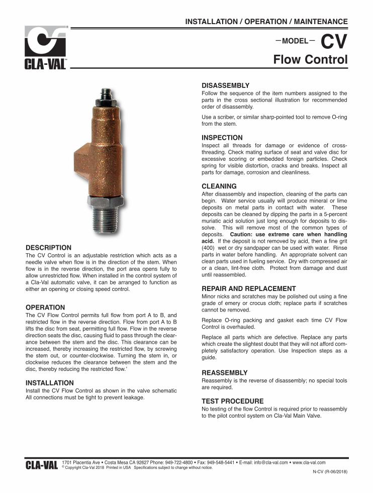
DESCRIPTIONThe CV Control is an adjustable restriction which acts as aneedle valve when flow is in the direction of the stem. Whenflow is in the reverse direction, the port area opens fully toallow unrestricted flow. When installed in the control system ofa Cla-Val automatic valve, it can be arranged to function aseither an opening or closing speed control.
OPERATIONThe CV Flow Control permits full flow from port A to B, andrestricted flow in the reverse direction. Flow from port A to Blifts the disc from seat, permitting full flow. Flow in the reversedirection seats the disc, causing fluid to pass through the clear-ance between the stem and the disc. This clearance can beincreased, thereby increasing the restricted flow, by screwingthe stem out, or counter-clockwise. Turning the stem in, orclockwise reduces the clearance between the stem and thedisc, thereby reducing the restricted flow.’
INSTALLATIONInstall the CV Flow Control as shown in the valve schematicAll connections must be tight to prevent leakage.
DISASSEMBLYFollow the sequence of the item numbers assigned to theparts in the cross sectional illustration for recommendedorder of disassembly.Use a scriber, or similar sharp-pointed tool to remove O-ringfrom the stem.
INSPECTIONInspect all threads for damage or evidence of cross-threading. Check mating surface of seat and valve disc forexcessive scoring or embedded foreign particles. Checkspring for visible distortion, cracks and breaks. Inspect allparts for damage, corrosion and cleanliness.
CLEANING After disassembly and inspection, cleaning of the parts canbegin. Water service usually will produce mineral or limedeposits on metal parts in contact with water. Thesedeposits can be cleaned by dipping the parts in a 5-percentmuriatic acid solution just long enough for deposits to dis-solve. This will remove most of the common types ofdeposits. Caution: use extreme care when handlingacid. If the deposit is not removed by acid, then a fine grit(400) wet or dry sandpaper can be used with water. Rinseparts in water before handling. An appropriate solvent canclean parts used in fueling service. Dry with compressed airor a clean, lint-free cloth. Protect from damage and dustuntil reassembled.
REPAIR AND REPLACEMENTMinor nicks and scratches may be polished out using a finegrade of emery or crocus cloth; replace parts if scratchescannot be removed.Replace O-ring packing and gasket each time CV FlowControl is overhauled.Replace all parts which are defective. Replace any partswhich create the slightest doubt that they will not afford com-pletely satisfactory operation. Use Inspection steps as aguide.
REASSEMBLYReassembly is the reverse of disassembly; no special toolsare required.
TEST PROCEDURENo testing of the flow Control is required prior to reassemblyto the pilot control system on Cla-Val Main Valve.
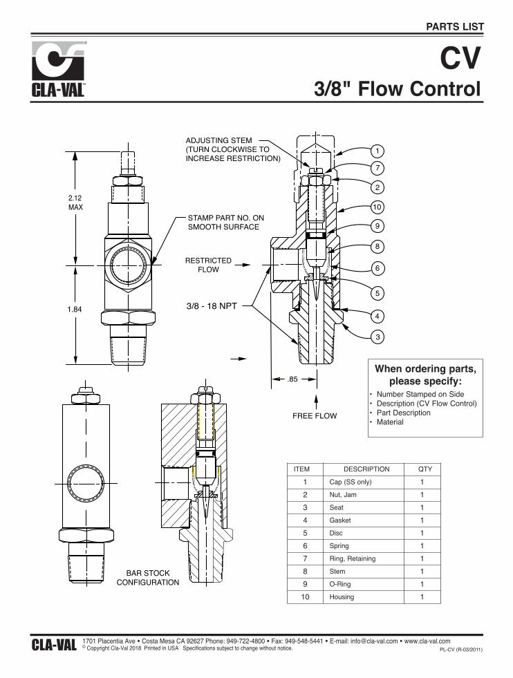
3/8" Flow ControlCV
2.12MAX
STAMP PART NO. ONSMOOTH SURFACE
RESTRICTEDFLOW
3/8 - 18 NPT1.84
ADJUSTING STEM(TURN CLOCKWISE TOINCREASE RESTRICTION)
1
7
2
10
9
8
6
5
4
3
.85
FREE FLOW
BAR STOCKCONFIGURATION
When ordering parts,please specify:
• Number Stamped on Side • Description (CV Flow Control)• Part Description• Material
CLA-VAL Copyright Cla-Val 2018 Printed in USA Specifications subject to change without notice. 1701 Placentia Ave • Costa Mesa CA 92627 Phone: 949-722-4800 • Fax: 949-548-5441 • E-mail: [email protected] • www.cla-val.com
© PL-CV (R-03/2011)
PARTS LIST
ITEM DESCRIPTION QTY1 Cap (SS only) 12 Nut, Jam 13 Seat 14 Gasket 15 Disc 16 Spring 17 Ring, Retaining 18 Stem 19 O-Ring 1
10 Housing 1

Cla-Val ProductIdentification
Proper Identification
For ordering repair kits, replacement parts, or forinquiries concerning valve operation, it is important toproperly identify Cla-Val products already in serviceby including all nameplate data with your inquiry.Pertinent product data includes valve function, size,material, pressure rating, end details, type of pilotcontrols used and control adjustment ranges.
Identification Plates
For product identification, cast-in body markings aresupplemented by identification plates as illustrated onthis page. The plates, depending on type and size ofproduct, are mounted in the most practical position. Itis extremely important that these identificationplates are not painted over, removed, or in anyother way rendered illegible.
INLETEINTRITTENTREEENTRADA
SIZE &CAT NO.
STOCKNO. CODE
MFD. BY CLA-VALNEWPORT BEACH, CALIF, U.S.A.
RESERVOIREND
INLET
INLET
SIZE &CAT NO.
STOCKNO.
FLOWMFD. BY CLA-VAL NEWPORT BEACH, CALIF. U.S.A.
CODE
C
®
™
SIZE &CAT NO.
STOCKNO.
SPRINGRANGE
MFD. BY CLA-VAL NEWPORT BEACH, CALIF. U.S.A.
SIZE &CAT NO.
STOCKNO.
CODE
MFD. BY CLA-VALNEWPORT BEACH, CALIF.
U.S.A.
C
®
™
DO NOT REMOVE
THIS VALVE HAS BEEN MODIFIEDSINCE ORIGINAL SHIPMENT FROMFACTORY. WHEN ORDERING PARTSAND/ OR SERVICE SUPPLY DATA FROMTHIS PLATE & ALL OTHER PLATES ON ORIGINAL VALVE.
REDUCED PRESSURE BACKFLOW PREVENTION DEVICE
STK.NO.
SER.NO.
CAT.
NO.RP-4
CLA-VAL NEWPORT BEACH, CA.
This brass plate appears on valves sized 21/2" and largerand is located on the top of the inlet flange.
These two brass plates appear on 3/8", 1/2", and 3/4" sizevalves and are located on the valve cover.
These two brass plates appear on threaded valves
1" through 3" size or flanged valves 1" through 2".It is located on only one side of the valve body.
This brass plate appears on altitude valves only and isfound on top of the outlet flange.
This brass plate is used to identify pilot control valves.The adjustment range is stamped into the plate.
This tag is affixed to the cover of the pilot control valve.The adjustment range appears in the spring range section.
This aluminum plate is included in pilot systemmodification kits and is to be wired to the new pilot
control system after installation.
This brass plate is used on our backflow preventionassemblies. It is located on the side of the Number Two
check (2" through 10"). The serial number of theassembly is also stamped on the top of the inlet flange of
the Number One check.
How to Order
HOW TO ORDER
Because of the vast number of possible configurations andcombinations available, many valves and controls are notshown in published product and price lists. For orderinginformation, price and availability on product that are not listed,please contact your local Cla-Val office or our factory officelocated at:
SPECIFY WHEN ORDERING• Model Number • Valve Size• Globe or Angle Pattern • Threaded or Flanged• Adjustment Range • Body and Trim Materials(As Applicable) • Optional Features
• Pressure Class
UNLESS OTHERWISE SPECIFIED• Globe or angle pattern are the same price• Ductile iron body and bronze trim are standard• X46 Flow Clean Strainer or X43 “Y” Strainer are included• CK2 Isolation Valves are included in price on 4" and larger valve sizes (6" and larger on 600 Series)
P. O. Box 1325Newport Beach, California 92659-0325
(949) 722-4800FAX (949) 548-5441
LIMITED WARRANTYAutomatic valves and controls as manufactured by Cla-Val are warrantedfor three years from date of shipment against manufacturing defects inmaterial and workmanship that develop in the service for which they aredesigned, provided the products are installed and used in accordancewith all applicable instructions and limitations issued by Cla-Val.Electronic components manufactured by Cla-Val are warranted for oneyear from the date of shipment.
We will repair or replace defective material, free of charge, that is returnedto our factory, transportation charges prepaid, if upon inspection, thematerial is found to have been defective at time of original shipment. Thiswarranty is expressly conditioned on the purchaser’s providing writtennotification to Cla-Val immediate upon discovery of the defect.
Components used by Cla-Val but manufactured by others, are warrantedonly to the extent of that manufacturer’s guarantee.
This warranty shall not apply if the product has been altered or repaired byothers, Cla-Val shall make no allowance or credit for such repairs oralterations unless authorized in writing by Cla-Val.
DISCLAIMER OF WARRANTIES AND LIMITATIONS OF LIABILITYThe foregoing warranty is exclusive and in lieu of all otherwarranties and representations, whether expressed, implied, oral orwritten, including but not limited to any implied warranties ormerchantability or fitness for a particular purpose. All such otherwarranties and representations are hereby cancelled.
Cla-Val shall not be liable for any incidental or consequential loss,damage or expense arising directly or indirectly from the use of theproduct. Cla-Val shall not be liable for any damages or charges forlabor or expense in making repairs or adjustments to the product.Cla-Val shall not be liable for any damages or charges sustained inthe adaptation or use of its engineering data and services. Norepresentative of Cla-Val may change any of the foregoing orassume any additional liability or responsibility in connection withthe product. The l iabil i ty of Cla-Val is l imited to materialreplacements F.O.B. Newport Beach, California.
TERMS OF SALE
ACCEPTANCE OF ORDERS
All orders are subject to acceptance by our main office at Newport Beach, California.
CREDIT TERMS
Credit terms are net thirty (30) days from date of invoice.
PURCHASE ORDER FORMS
Orders submitted on customer’s own purchase order forms will be accepted onlywith the express understanding that no statements, clauses, or conditions containedin said order form will be binding on the Seller if they in any way modify the Seller’sown terms and conditions of sales.
PRODUCT CHANGES
The right is reserved to make changes in pattern, design or materials when deemednecessary, without prior notice.
PRICES
All prices are F.O.B. Newport Beach, California unless expressly stated otherwise onour acknowledgement of the order. Prices are subject to change without notice. Theprices at which any order is accepted are subject to adjustment to the Seller’s pricein effect at the time of shipment. Prices do not include sales, excise, municipal, stateor any other Government taxes. Minimum order charge $100.00.
RESPONSIBILITY
We will not be responsible for delays resulting from strikes, accidents, negligence ofcarriers, or other causes beyond our control. Also, we will not be liable for anyunauthorized product alterations or charges accruing there from.
RISK
All goods are shipped at the risk of the purchaser after they have been delivered byus to the carrier. Claims for error, shortages, etc., must be made upon receipt ofgoods.
EXPORT SHIPMENTS
Export shipments are subject to an additional charge for export packing.
RETURNED GOODS
1. Customers must obtain written approval from Cla-Val prior to returning anymaterial.
2. Cla-Val reserves the right to refuse the return of any products.
3. Products more than six (6) months old cannot be returned for credit.
4. Specially produced, non-standard models cannot be returned for credit.
5. Rubber goods such as diaphragms, discs, o-rings, etc., cannot be returned forcredit, unless as part of an unopened vacuum sealed repair kit which is lessthan six months old.
6. Goods authorized for return are subject to a 35% ($100 minimum) restockingcharge and a service charge for inspection, reconditioning, replacement ofrubber parts, retesting, repainting and repackaging as required.
7. Authorized returned goods must be packaged and shipped prepaid to Cla-Val,1701 Placentia Avenue, Costa Mesa, California 92627.
PO Box 1325 Newport Beach CA 92659-0325 Phone: 949-722-4800 Fax: 949-548-5441
CLA-VAL
CLA-VAL CANADA CLA-VAL EUROPE 4687 Christie DriveBeamsville, OntarioCanada L0R 1B4Phone: 905-563-4963Fax: 905-563-4040
Chemin dés Mesanges 1 CH-1032 Romanel/ Lausanne, Switzerland Phone: 41-21-643-15-55 Fax: 41-21-643-15-50
©COPYRIGHT CLA-VAL 2011 Printed in USASpecifications subject to change without notice. www.cla-val.com E-Product I.D. (R-3/2011)
Represented By:
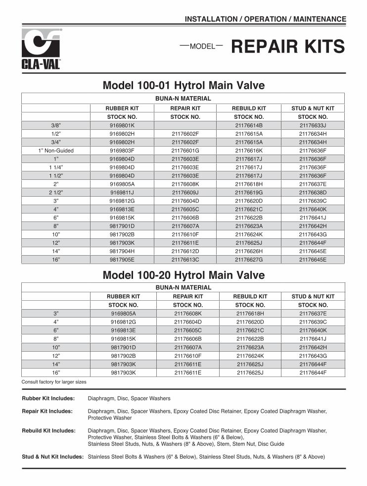
REPAIR KITSMODEL
INSTALLATION / OPERATION / MAINTENANCE
BUNA-N MATERIALRUBBER KIT REPAIR KIT REBUILD KIT STUD & NUT KITSTOCK NO. STOCK NO. STOCK NO. STOCK NO.
3/8” 9169801K 21176614B 21176633J1/2” 9169802H 21176602F 21176615A 21176634H3/4” 9169802H 21176602F 21176615A 21176634H
1” Non-Guided 9169803F 21176601G 21176616K 21176636F1” 9169804D 21176603E 21176617J 21176636F
1 1/4” 9169804D 21176603E 21176617J 21176636F1 1/2” 9169804D 21176603E 21176617J 21176636F
2” 9169805A 21176608K 21176618H 21176637E2 1/2” 9169811J 21176609J 21176619G 21176638D
3” 9169812G 21176604D 21176620D 21176639C4” 9169813E 21176605C 21176621C 21176640K6” 9169815K 21176606B 21176622B 21176641J8” 9817901D 21176607A 21176623A 21176642H
10” 9817902B 21176610F 21176624K 21176643G12” 9817903K 21176611E 21176625J 21176644F14” 9817904H 21176612D 21176626H 21176645E16” 9817905E 21176613C 21176627G 21176645E
Consult factory for larger sizes
BUNA-N MATERIALRUBBER KIT REPAIR KIT REBUILD KIT STUD & NUT KITSTOCK NO. STOCK NO. STOCK NO. STOCK NO.
3” 9169805A 21176608K 21176618H 21176637E4” 9169812G 21176604D 21176620D 21176639C6” 9169813E 21176605C 21176621C 21176640K8” 9169815K 21176606B 21176622B 21176641J
10” 9817901D 21176607A 21176623A 21176642H12” 9817902B 21176610F 21176624K 21176643G14” 9817903K 21176611E 21176625J 21176644F16” 9817903K 21176611E 21176625J 21176644F
Model 100-01 Hytrol Main Valve
Model 100-20 Hytrol Main Valve
Rubber Kit Includes: Diaphragm, Disc, Spacer Washers
Repair Kit Includes: Diaphragm, Disc, Spacer Washers, Epoxy Coated Disc Retainer, Epoxy Coated Diaphragm Washer, Protective Washer
Rebuild Kit Includes: Diaphragm, Disc, Spacer Washers, Epoxy Coated Disc Retainer, Epoxy Coated Diaphragm Washer, Protective Washer, Stainless Steel Bolts & Washers (6" & Below), Stainless Steel Studs, Nuts, & Washers (8" & Above), Stem, Stem Nut, Disc Guide
Stud & Nut Kit Includes: Stainless Steel Bolts & Washers (6" & Below), Stainless Steel Studs, Nuts, & Washers (8" & Above)

Repair Kits for 100-04/100-23 Hy-Check Main ValvesFor: Hy-Check Main Valves—150 Pressure Class Only Includes: Diaphragm, Disc and O-Rings and full set of spare Spacer Washers.
Larger Sizes: Consult Factory.
Repair Kits for 100-02/100-21 Powertrol and 100-03/100-22 Powercheck Main ValvesFor: Powertrol and Powercheck Main Valves—150 Pressure Class Only Includes: Diaphragm, Disc (or Disc Assembly) and O-rings and full set of spare Spacer Washers.
Repair Kits for Pilot Control Valves (In Standard Materials Only)Includes: Diaphragm, Disc (or Disc Assembly), O-Rings, Gaskets or spare Screws as appropriate.
Repair Assemblies (In Standard Materials Only)
CLA-VAL Copyright Cla-Val 2018 Printed in USA Specifications subject to change without notice. 1701 Placentia Ave • Costa Mesa CA 92627 Phone: 949-722-4800 • Fax: 949-548-5441 • E-mail: [email protected] • www.cla-val.com
© N-RK (R-08/2018)
ValveSize
Kit Stock Number100-02
ValveSize
Kit Stock Number100-02 & 100-03 100-21 & 100-22
3⁄8” 9169901H 21⁄2” 9169910J N/A1⁄2” & 3⁄4” 9169902F 3” 9169911G 9169905J
1” 9169903D 4” 9169912E 9169911G11⁄4” & 11⁄2” 9169904B 6” 9169913C 9169912E
2” 9169905J 8” 99116G 9169913C10” 9169939H 99116G12” 9169937B 9169939H
ValveSize
Kit Stock Number ValveSize
Kit Stock Number100-04 100-23 100-04 100-23
4” 20210901B N/A 12” 20210905H 20210904J6” 20210902A 20210901B 14” 20210906G N/A8” 20210903K 20210902A 16” 20210907F 20210905H
10” 20210904J 20210903K 20” N/A 20210907F24” N/A 20210907F
BUNA-N® (Standard Material) VITON (For KB Controls)Pilot
ControlKit StockNumber
PilotControl
Kit StockNumber
PilotControl
Kit StockNumber
CDB 9170006C CFM-9 12223E CDB-KB 9170012ACDB-30 9170023H CRA (w/bucking spring) 9170001D CRA-KB N/ACDB-31 9170024F CRD (w/bucking spring) 9170002B CRD-KB (w/bucking spring) 9170008JCDB-7 9170017K CRD (no bucking spring) 9170003K CRL-KB 9170013JCDH-2 18225D CRD-18 20275401K CDHS-2BKB 9170010ECDHS-2 44607A CRD-22 98923G CDHS-2FKB 9170011CCDHS-2B 9170004H CRL (55F, 55L) 9170007A CDHS-18KB (no bucking spring) 9170009GCDHS-2F 9170005E CRL60/55L-60 9170033G 102C-KB 1726202DCDHS-3C-A2 24657K CRL60/55L60 1" 9170042HCDHS-8A 2666901A CRL-4A 43413ECDHS-18 9170003K CRL-5 (55B) 65755BCDS-4 9170014G CRL-5A (55G) 20666ECDS-5 14200A CRL-18 20309801CCDS-6 20119301A Universal CRL 9170041KCDS-6A 20349401C CV 9170019FCFCM-M1 1222301C X105L (O-ring) 00951E Buna-N®CFM-2 12223E 102B-1 1502201FCFM-7 1263901K 102C-2 1726201F CRD Disc Ret. (Solid) C5256HCFM-7A 1263901K 102C-3 1726201F CRD Disc Ret. (Spring) C5255K
Control Description Stock NumberCF1-C1 Pilot Assembly Only 89541HCF1-Cl Complete Float Control less Ball and Rod 89016ACFC2-C1 Disc, Distributor and Seals 2674701ECSM 11-A2-2 Mechanical Parts Assembly 97544BCSM 11-A2-2 Pilot Assembly Only 18053K33A 1” Complete Internal Assembly and Seal 2036030B33A 2” Complete Internal Assembly and Seal 2040830J
When ordering, please give complete nameplate data of the valve and/or control being repaired. MINIMUM ORDER CHARGE APPLIES
Larger Sizes: Consult Factory.