48th aiaa aerospace science meeting conference …...48th aiaa aerospace science meeting conference...
TRANSCRIPT

48th AIAA Aerospace Science Meeting Conference AIAA 2010-245 Jan., 4-7, 2010, Orlando, FL
1
American Institute of Aeronautics and Astronautics This material is declared a work of the U.S. Government and is not subject to copyright protection in the United States.
Application of a Near Infrared Imaging System
for Thermographic Imaging of the Space Shuttle during
Hypersonic Re-Entry Joseph N. Zalameda, Alan B. Tietjen
*, Thomas J. Horvath, Deborah M. Tomek
NASA Langley Research Center, Hampton VA 23681
David M. Gibson, Jeff C. Taylor
Johns Hopkins University Applied Physics Laboratory, Laurel, MD 20723
Steve Tack
Naval Air Warfare Center - Weapons Division, Pt. Mugu, CA 93042
Brett C. Bush
Raytheon/Photon Research Associates, San Diego, CA 92121
C. David Mercer
Aerospace Computing Inc., Hampton VA 23681
Edward J. Shea
Futron Corporation, Hampton, VA 23666
High resolution calibrated near infrared (NIR) imagery was obtained of the Space Shuttle’s re-
entry during STS-119, STS-125, and STS-128 missions. The infrared imagery was collected using a US
Navy NP-3D Orion aircraft using a long-range infrared optical package referred to as Cast Glance.
The slant ranges between the Space Shuttle and Cast Glance were approximately 26-41 nautical miles
at point of closest approach. The Hypersonic Thermodynamic Infrared Measurements (HYTHIRM)
project was a NASA Langley led endeavor sponsored by the NASA Engineering Safety Center, the
Space Shuttle Program Office and the NASA Aeronautics Research Mission Directorate to demon-
strate a quantitative thermal imaging capability. HYTHIRM required several mission tools to acquire
the imagery. These tools include pre-mission acquisition simulations of the Shuttle trajectory in rela-
tionship to the Cast Glance aircraft flight path, radiance modeling to predict the infrared response of
the Shuttle, and post mission analysis tools to process the infrared imagery to quantitative temperature
maps. The spatially resolved global thermal measurements made during the Shuttle’s hypersonic re-
entry provides valuable flight data for reducing the uncertainty associated with present day ground-to-
flight extrapolation techniques and current state-of-the-art empirical boundary-layer transition or
turbulent heating prediction methods. Laminar and turbulent flight data is considered critical for the
development of turbulence models supporting NASA’s next-generation spacecraft. This paper will
provide the motivation and details behind the use of an upgraded NIR imaging system used onboard a
Navy Cast Glance aircraft and describe the characterizations and procedures performed to obtain
quantitative temperature maps. A brief description and assessment will be provided of the previously
used analog NIR camera along with image examples from Shuttle missions STS-121, STS-115, and so-
lar tower test. These thermal observations confirmed the challenge of a long-range acquisition during
re-entry. These challenges are due to unknown atmospheric conditions, image saturation, vibration
etc. This provides the motivation for the use of a digital NIR sensor. The characterizations performed
on the digital NIR sensor included radiometric, spatial, and spectral measurements using blackbody
radiation sources and known targets. An assessment of the collected data for three Space Shuttle at-
mospheric re-entries, STS-119, STS-125, and STS-128, are provided along with a description of various
events of interest captured using the digital NIR imaging system such as RCS firings and boundary
layer transitions. Lastly the process used to convert the raw image counts to quantitative temperatures
is presented along with comparisons to the Space Shuttle’s onboard thermocouples.
* ISTEF CSC, Kennedy Space Center, FL 32899
https://ntrs.nasa.gov/search.jsp?R=20100004853 2020-07-29T10:00:18+00:00Z

AIAA 2010-245
American Institute of Aeronautics and Astronautics
2
Nomenclature
i counts
k counts threshold
n acquired image or frame number
N estimated Shuttle pixel resolution
Acronyms
ABLT asymmetric boundary layer transition
BLT boundary layer transition
CAPS computer aided pointing system
CCD charge coupled device
CFD computational fluid dynamics
DTO detailed test objective
FITS flexible image transport system
GMT Greenwich mean time
HYTHIRM hypersonic thermodynamic infrared measurement
IRIG inter-range instrumentation group
MODTRAN moderate resolution atmospheric transmission
NIR near infrared
NM nautical miles
PCA point of closest approach
RCG reaction cured glass
RCS reaction control system
SNR signal to noise ratio
I. Introduction
This paper describes the motivation and details behind the use of a digital NIR imaging system used onboard a
Navy Cast Glance aircraft and describe the characterizations and procedure performed to obtain quantitative tem-
perature imagery of the Space Shuttle during hypersonic re-entry. The NASA Langley Research Center led
Hypersonic THermodynamic InfraRed Measurement (HYTHIRM) project culminated in the acquisition of high-
resolution calibrated infrared imagery of the Space Shuttle during hypersonic atmospheric entry for STS-119, STS-
125 and STS-128 missions flown in 2009. The thermal imaging provided a unique and never before observed per-
spective on the global distribution of surface temperature and the state of the airflow (i.e., laminar/turbulent) over
the entire windward surface of the Shuttle during hypersonic re-entry1. The thermal imagery represented several
years of advocacy within the aerothermodynamics technical community, sponsorship by the NASA Engineering
Safety Center, the Space Shuttle Program Office, the Hypersonic project within the NASA Aeronautics Research
Mission Directorate, and careful planning and mission execution by a coalition of NASA, Navy, government labs,
and contractor personnel. On Space Shuttle Discovery’s March 2009 STS-119 mission, NASA flew a specially
modified thermal protection system tile and instrumentation package to monitor heating effects from boundary layer
transition (BLT) during re-entry2. BLT occurs when the smooth, laminar flow of air close to the Shuttle’s surface is
disturbed and becomes turbulent resulting in surface temperature increases. On STS-119, the windward airflow on
the port wing was deliberately disrupted by a four-inch wide and quarter-inch tall "speed bump" built into the modi-
fied tile intended to promote transition to turbulence near Mach 15. In coordination with this flight experiment, the
HYTHIRM team positioned a US Navy NP-3D Orion aircraft approximately 28 nautical miles below Discovery and
remotely monitored surface temperature of the Shuttle at Mach 8.4 using a long-range infrared optical package re-
ferred to as Cast Glance3. The imagery from this mission not only captured the expected thermal footprint of the
turbulent flow downstream of the wing protuberance, but a much larger area of turbulent flow on the opposing star-
board wing that was not anticipated. The global thermal imagery obtained from the aircraft complemented the data
collected with an onboard instrumentation package consisting of strategically placed thermocouples.
Approximately two months later, May 2009, the same Navy aircraft successfully monitored the surface tempera-
tures of STS-125, Shuttle Atlantis not configured with a speed bump, traveling at approximately Mach 14.3 during

AIAA 2010-245
American Institute of Aeronautics and Astronautics
3
its return from the successful Hubble repair mission. During September 2009, STS-128 Discovery outfitted with a
slightly taller bump (0.35 inches tall) intended to promote transition to turbulence near Mach 18, had a successful
encounter with the P-3 at Mach 14.7. Collectively, the spatially resolved global thermal measurements made during
the Shuttle’s hypersonic re-entry were intended to demonstrate the capability to collect scientific quality imagery in
a reliable manner using available technology1. It is the intent of the project to analyze the imagery and provide the
technical community critical flight data for reducing the uncertainty associated with present day ground-to-flight
extrapolation techniques and current state-of-the-art empirical BLT or turbulent heating prediction methods. Lami-
nar and turbulent flight data is considered critical for the validation of physics-based prediction methods, to
stimulate the validation of laminar numerical models and the development of turbulence models supporting NASA’s
next-generation spacecraft under the Constellation program.
This paper will provide the motivation and details behind the use of a digital NIR imaging system and describe
the characterizations and procedure performed to obtain quantitative temperature imagery. Past attempts by the Cast
Glance aircraft to image the Space Shuttle during STS-121 and STS-115 missions has resulted in successful image
captures, however the quality of the acquired data allowed for limited data processing4,5,6,7
. During both missions,
the Shuttle imagery was obtained using an analog based NIR imaging system, however due to image saturation, lim-
ited quantitative analysis could be performed. As a result, the analog NIR imaging system onboard the Cast Glance
aircraft was characterized during a series of solar tower experiments. The solar tower tests were conducted at the
Sandia National Laboratories’ National Solar Thermal Test Facility in Albuquerque, New Mexico and consisted of
imaging an 8x8 array of Shuttle tiles with Reaction Cured Glass (RCG) coatings. The tile array was instrumented
with thermocouples. A series of solar reflectance mirrors were used to heat the array up to 2,000ºF and flight NIR
data from Cast Glance were obtained. As a result of these tests, the recommendation was made to enhance the ana-
log NIR imaging system with a digital NIR imaging camera and characterize the new camera. The characterizations
performed on the digital NIR system included radiometric, spatial, and spectral measurements using blackbody ra-
diation sources and known targets. The radiometric characterization was performed using calibrated blackbodies set
at various temperatures. This characterization was used as input to a radiance model8 to predict the imaged NIR ra-
diometric response of the Shuttle and allow for proper selection of the digital camera integration time to minimize
pixel saturation. The spatial characterization was performed during flight conditions on selected stars. This tech-
nique allows for an estimation of the spatial response of the Cast Glance imaging system. The spectral
characterization involved using a series of long pass filters with known spectral responses. Implementation of the
digital NIR camera system has resulted in NIR imagery with improved dynamic range, instantaneous field of view,
and signal to noise. An assessment of the collected data, using the digital NIR imaging sensor, for STS-119, STS-
125, and STS-128, is provided. This assessment of the quality of the thermal imagery includes total number of im-
ages acquired, number of saturated pixels, integration time adjustments vs. image number, and estimated pixel
resolution. In addition, imagery of interest captured using the NIR imaging system such as RCS firings and BLT are
presented. The process used to convert the raw image counts to quantitative 2-dimensional temperature images us-
ing Moderate Resolution Atmospheric Transmission (MODTRAN)9 corrections is presented. A more rigorous
analysis of the thermal imagery including 3-dimensional mapping is discussed in Ref. 8. Lastly, the HYTHIRM
remotely measured temperature values are compared to the Space Shuttle’s onboard thermocouples.
II. Description and Imaging Results of Analog NIR Imaging System
A picture of the Cast Glance aircraft, NIR optical tracking system, and analog NIR camera is shown in Fig. 1.
Additional details about the Cast Glance aircraft can be found in Ref. 3. The analog NIR camera is the Cohu model
2672 with a charge coupled device (CCD) sensor of pixel array size of 752 x 582. The camera signal to noise value
is approximately 55 dB. A long pass filter with cut on at 0.750 m is used to remove the spectral energy in the visi-
ble band. The imaging optics utilizes a 7-inch aperture reflecting telescope viewing through the forward starboard
visible/NIR window. The optics are vibration isolated and gyroscope stabilized to minimize image jitter, improve
pointing accuracy, and allows for manual tracking (preferred method). The NIR imaging system spectral response is
0.850 – 1.1 m. Shown in Fig. 2 is the analog camera system layout. To minimize potential saturation during a
mission, the integration time can be changed in discrete steps of 0.008, 0.004, 0.002, 0.001, 0.0005, 0.00025, and
0.0001 seconds using a manually adjusted dial. The RS 170 analog video is connected to a Computer Aided Point-
ing System (CAPS) for inserting aircraft Global Positioning System information, altitude, gimbal pointing angle,
and ground speed. The analog video is then connected to a video distribution amplifier where the video is split to an
object tracking monitor and video time inserter. After the images are time stamped, the analog video is recorded on a
mini-DVCAMTM
tape. The dynamic range of the recorded images is 8 bits and the frame rate is 30 Hz. Past at-
tempts by the Cast Glance aircraft to image the Space Shuttle during STS-121 (July 2006) and STS-115 (September

AIAA 2010-245
American Institute of Aeronautics and Astronautics
4
Fig. 1. Cast Glance analog NIR imaging system. Fig. 2. Cast Glance analog NIR video signal layout.
2006) missions resulted in some success using the NIR analog system. During both missions, the Shuttle imagery
was obtained, however due to image saturation limited quantitative analysis could be performed.
Example images are obtained by converting the mini-DVCAM video information into uncompressed digital
files. Shown in Fig. 3 is the raw intensity image from STS-121 captured by Cast Glance aircraft at the approximate
point of closest approach (PCA). The threshold image (saturated pixels highlighted in red) indicates significant im-
age saturation over most of the windward surface of the vehicle. A partial histogram plot is also shown in Fig 3
indicating a significant number of saturated pixels. Shown in Fig. 4 is the raw intensity image from STS-115 cap-
tured by Cast Glance aircraft at approximate PCA. The threshold image shows saturated pixels at the Shuttle nose,
Fig. 3. Cast Glance raw NIR intensity image from STS-121 during re-entry with saturated pixels (red) and
corresponding image histogram.
Fig. 4. Cast Glance raw NIR intensity image from STS-115 during re-entry with saturated pixels (red) and
corresponding image histogram.

AIAA 2010-245
American Institute of Aeronautics and Astronautics
5
wing leading edges, and body flap. A partial histogram plot is also shown in Fig 4 indicating the number of satu-
rated pixels. Although the number of saturated pixels is small compared to STS-121 data, the slant range or optical
path length is longer thus lowering the total number of pixels on target. This lower resolution image emphasizes the
importance of each unsaturated pixel. A data collect priority is to minimize the number of saturated pixels during
data acquisition. This can be challenging due to unknown atmospheric effects over a long optical path length that is
changing with the approaching Shuttle target.
As a result the analog NIR imaging system onboard the Cast Glance aircraft was characterized during a series of
solar tower experiments. The solar tower tests were conducted at the Sandia National Laboratories’ National Solar
Thermal Test Facility in Albuquerque, New Mexico10
. Shown in Fig. 5 is the series of mirrors used to reflect the
solar energy onto a tile array mounted on top of the tower. The testing consisted of imaging an 8x8 array of Space
Shuttle RCG coated tiles during and after the application of solar energy. The 8x8 tile array (1.2 meter x 1.2 meter
in size) was instrumented with thermocouples. A visible image of the tile array, partially illuminated, is shown in
Fig. 6. A series of solar reflectance mirrors were used to heat the array up to 2,000ºF and flight NIR data from Cast
Glance was obtained. An example NIR image is shown in Fig. 7 and was acquired at a slant range of approximately
5 NM and shows the tile array partially illuminated during cool down. For a given camera integration time, multiple
frames during the cooling process were used to produce a calibration curve by using the known thermocouple val-
ues. Before using the images for analysis, a spatial stabilization algorithm based on object tracking through image
correlation, was used to remove jitter. This allows for determining the area mean counts over the tile array as a
Fig. 5. Solar tower testing facility. Fig. 6. Visible image of tile array. Fig. 7. Cast Glance NIR image.
function of time. The tile array radiant exitance was determined by averaging the thermocouple temperature values
for a given area of interest using a known tile emissivity value. For a given surface area, the radiant exitance was
converted to the in-band radiance11
. The radiant energy or radiance was corrected for atmospheric path transmis-
sion, solar scattering from aerosols, and path radiance to produce the in-band radiance at the sensor aperture. These
values were compared to the area-mean counts to produce a calibration curve. The calibration curve was then used
to convert the image counts to object radiance for a given integration time taking into account the MODTRAN at-
mospheric modeling. The object radiance was converted to temperature by using Planck’s black body radiation
law12
and known tile emissivity. Using this technique, a temperature image of the tile array can be calculated as
shown in Fig. 8. The conversion of temperature using the analog NIR imaging system radiometric uncertainty is
also shown in Table 1. As expected the lower the temperature the larger the 2 sigma errors due to the limitation of
Table 1. Noise performance of analog camera.
Fig. 8 .Temperature image of tile array.

AIAA 2010-245
American Institute of Aeronautics and Astronautics
6
the CCD sensor sensitivity at longer wavelengths. For the temperature range of interest, typical of a Shuttle re-
entry, the averaged 2-sigma errors (from Table 1) are greater than +/- 190 ºF. These error values include both sensor
noise and tile-to-tile emissivity non-uniformity. In addition it was noted the sensor saturation level was at 155
counts for the solar tower test data. This is much lower than the expected 8 bit (256 counts) dynamic range. This
reduced dynamic range could have been the result of an incorrect gain or offset level in the camera electronics. As a
result of these tests, showing poor signal to noise and limited dynamic range, the recommendation was made to re-
place the analog NIR sensor with a digital NIR imaging sensor and maintain the analog camera as a backup data
acquisition system.
III. Description and Characterization of Digital NIR Imaging System
The digital NIR camera chosen to replace the analog camera is the Prosilica GC1380H. The camera pixel array
size is 1360x1024 with a frame rate of 30 Hz at full resolution. The pixel array size is approximately a factor of 3
larger than the analog camera, which allows for an improved instantaneous field of view. The camera’s dynamic
range is 12 bits, which is a factor of 16 better than the analog camera. This improved dynamic range will help to
minimize image saturation and or clipping. The integration time can be varied from 10 sec. to 60 sec. and is con-
tinuously variable. This feature is a great improvement over the analog camera stepped dial knob adjustment. The
camera has a GigE digital output. A laptop based digital acquisition system was developed to acquire the data, Fig
9a. The digital output improves signal to noise performance by reducing the cable noise associated with the analog
system. The quoted camera signal to noise value is approximately 66 dB about 4 times better that the analog NIR
camera. The spectral response of the camera’s CCD sensor is 0.4 – 1.1 m. A long pass filter with cut on at 0.850
m is used to remove the spectral energy in the visible band. A picture of the digital camera, installed on the air-
craft, is shown in Fig. 9b. The camera is half the size and weight. Size and weight are important considerations
when upgrading flight hardware. Shown, Fig. 9c, is the digital acquisition system block diagram. The acquired
digital data file is stored in the flexible image transport system (FITS) format13
. Frame acquisition time is stamped
with an inter-range instrumentation group (IRIG) time code provided by Cast Glance’s GPS timing system
Fig. 9. Digital data acquisition system and NIR camera installed onboard Cast Glance aircraft with system
layout diagram.
and the value is stored in the frame header. Custom data acquisition software was developed to control the camera’s
integration time in steps down to 10 sec. The integration time can be adjusted in real time using the computer’s
keypad in fine, medium, or coarse steps. In addition, the integration time can be incremented to predefined values
using the number keypad. The acquired digital video is displayed in real time on the computer’s display and satu-
rated pixels are colored in red. The characterizations performed on the digital NIR system included radiometric,
spatial, and spectral measurements using blackbody radiation sources and known targets. These characterizations
were used as input to the radiance model8 to predict the imaged NIR radiometric response of the Shuttle and allow
for proper selection of the digital camera integration time to minimize pixel saturation.
A. Radiometric
The radiometric characterization was performed pre-flight using calibrated blackbody radiation sources set at
various temperatures. The process involves the calibration of the measured radiance counts to actual temperature
values. The calibration was performed in a temperature range of interest (up to 1,900 ºF) at specified sensor integra-
tion times. The results are calibration curves that can then be used to convert the measured pixel intensity to
quantitative radiance values. A series of spot check calibrations were performed during each of the three, STS-119,
STS-125, and STS 128, data acquisition mission. This involved parking the Cast Glance aircraft at a known dis-
tance from the blackbody sources which is shown in Fig. 10a. The NIR imaging system tracking mirror is pointed at
AIAA 2010-245
American Institute of Aeronautics and Astronautics
7
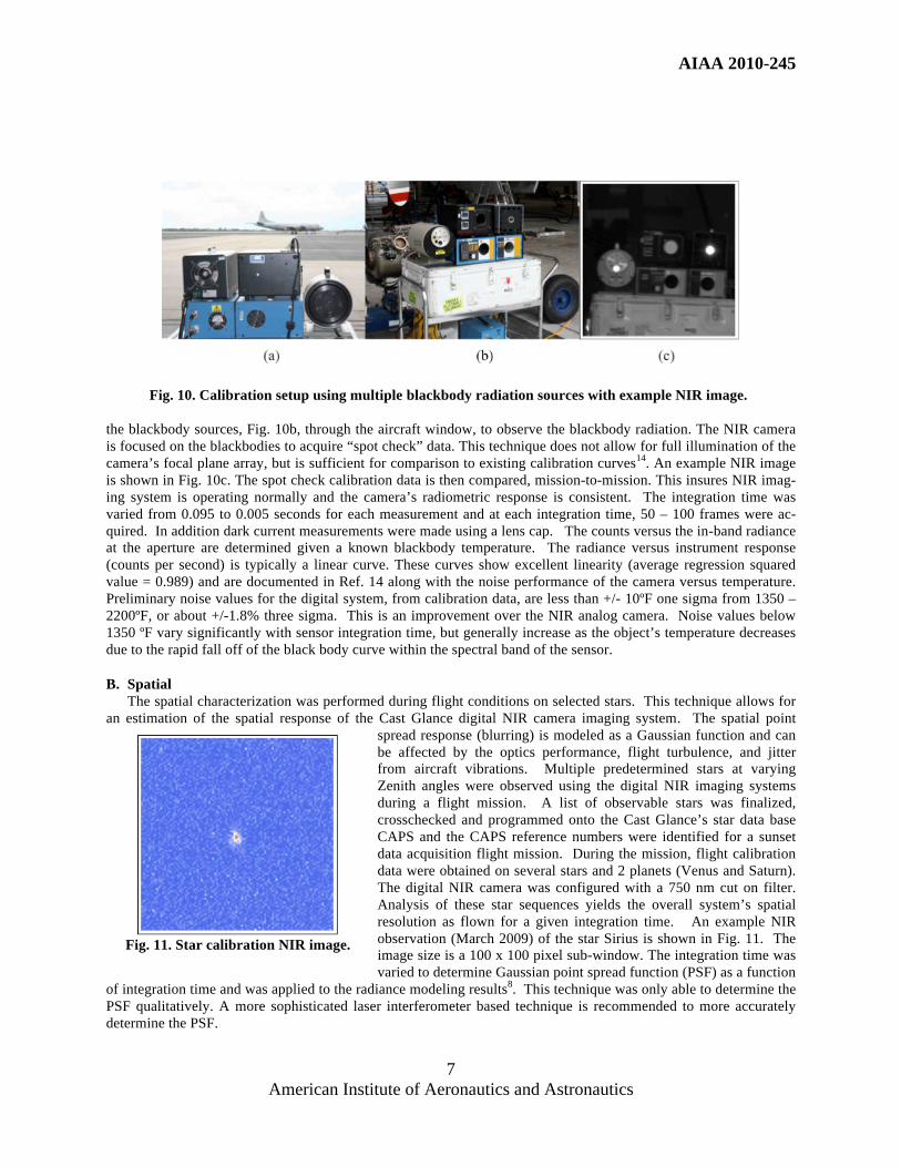
Fig. 10. Calibration setup using multiple blackbody radiation sources with example NIR image.
the blackbody sources, Fig. 10b, through the aircraft window, to observe the blackbody radiation. The NIR camera
is focused on the blackbodies to acquire “spot check” data. This technique does not allow for full illumination of the
camera’s focal plane array, but is sufficient for comparison to existing calibration curves14
. An example NIR image
is shown in Fig. 10c. The spot check calibration data is then compared, mission-to-mission. This insures NIR imag-
ing system is operating normally and the camera’s radiometric response is consistent. The integration time was
varied from 0.095 to 0.005 seconds for each measurement and at each integration time, 50 – 100 frames were ac-
quired. In addition dark current measurements were made using a lens cap. The counts versus the in-band radiance
at the aperture are determined given a known blackbody temperature. The radiance versus instrument response
(counts per second) is typically a linear curve. These curves show excellent linearity (average regression squared
value = 0.989) and are documented in Ref. 14 along with the noise performance of the camera versus temperature.
Preliminary noise values for the digital system, from calibration data, are less than +/- 10ºF one sigma from 1350 –
2200ºF, or about +/-1.8% three sigma. This is an improvement over the NIR analog camera. Noise values below
1350 ºF vary significantly with sensor integration time, but generally increase as the object’s temperature decreases
due to the rapid fall off of the black body curve within the spectral band of the sensor.
B. Spatial
The spatial characterization was performed during flight conditions on selected stars. This technique allows for
an estimation of the spatial response of the Cast Glance digital NIR camera imaging system. The spatial point
spread response (blurring) is modeled as a Gaussian function and can
be affected by the optics performance, flight turbulence, and jitter
from aircraft vibrations. Multiple predetermined stars at varying
Zenith angles were observed using the digital NIR imaging systems
during a flight mission. A list of observable stars was finalized,
crosschecked and programmed onto the Cast Glance’s star data base
CAPS and the CAPS reference numbers were identified for a sunset
data acquisition flight mission. During the mission, flight calibration
data were obtained on several stars and 2 planets (Venus and Saturn).
The digital NIR camera was configured with a 750 nm cut on filter.
Analysis of these star sequences yields the overall system’s spatial
resolution as flown for a given integration time. An example NIR
observation (March 2009) of the star Sirius is shown in Fig. 11. The
image size is a 100 x 100 pixel sub-window. The integration time was
varied to determine Gaussian point spread function (PSF) as a function
of integration time and was applied to the radiance modeling results8. This technique was only able to determine the
PSF qualitatively. A more sophisticated laser interferometer based technique is recommended to more accurately
determine the PSF.
Fig. 11. Star calibration NIR image.

AIAA 2010-245
American Institute of Aeronautics and Astronautics
8
C. Spectral
The spectral characterization involved using a series of long pass filters with known spectral responses. This al-
lows an estimate of the spectral response of the Cast Glance NIR imaging system using the digital NIR camera. For
a given blackbody temperature, the spectral response of the imaging system can then be measured using this tech-
nique and will allow for more accurate temperature measurements. Spectral calibrations were performed on the
digital NIR camera using 700, 750, 800, 850, 900, 950, 1,000 nanometer long pass NIR filters. The blackbody tem-
perature was set at 1,600 ºF. The integration time was varied from 0.08 to 0.000001 seconds for each measurement
and at each integration time 50 – 100 frames were acquired. Data were acquired without a filter (open) and for each
filter. The spectral response of the imaging system can then be determined using this technique. A drawback of this
technique is that the response is estimated in steps of 50 nanometers. The planned future use of a spectrometer will
allow for a more accurate determination of imaging system’s spectral response function and provide greater spectral
resolution. Therefore, the spectral response filter data was not used during the conversion to temperature.
IV. Assessment of STS-119, STS-125, and STS-128 Collected Data
An assessment of the collected data, using the digital NIR imaging sensor, for STS-119, STS-125, and STS-
128, are provided. Implementation of the digital NIR camera system has resulted in NIR imagery with improved
dynamic range, minimal saturation, and greater signal to noise. This assessment of the quality of the data col-
lected includes number of saturated pixels, signal to noise performance, integration time adjustments vs. image
number, and maximum number of pixels on target. In addition imagery of interest, captured using the NIR im-
aging system, such as reaction control system (RCS) firings, asymmetric boundary layer transition (ABLT), and
detailed test objective (DTO) BLT are presented.
A. STS-119 Mission
The US Navy NP-3D Orion Cast Glance aircraft, using the digital NIR imaging system, captured STS-119 Shut-
tle Discovery, OV-103, mission (March 28, 2009) during re-entry at a PCA slant range of approximately 26.2 NM at
GMT = 19:02:00, Fig.12. The total image acquisition time was over 9 minutes, the total number of acquired frames
n = 10,766 and the integration time was varied from 80 ms down to 10 ms, Fig. 13. The NIR acquisition file size
was over 21 Gigabytes. Typically the maximum resolution is obtained at PCA. At PCA the slant range between the
Shuttle and Cast Glance was 26.2 NM with corresponding image number = 3885, the pixel resolution is not at a
maximum, but is greatest at image number 3664. This is because the Shuttle is turning away from the aircraft at
PCA. This was determined using an image histogram analysis method. The image histogram analysis method was
used to analyze the NIR data frame by frame around PCA to determine the number of pixels on target and to deter-
mine the number of saturated pixels. The number of pixels on target is determined by summing the pixels with
counts above a threshold for each acquired frame. The equation is given as:
N = Bincounts i
i = k
4095
(1)
where i is the counts, k is the counts threshold value, and N is the estimated Shuttle pixel resolution. Because the
Fig. 12. STS-119 Cast Glance and Shuttle distance. Fig. 13. NIR camera integration times.

AIAA 2010-245
American Institute of Aeronautics and Astronautics
9
sky background is cool, compared to the Shuttle which is hot (higher pixel counts), the number of pixels associated
with the Shuttle’s windward surface can be estimated by summing all the pixels associated with a value greater than
250 counts (k = 250). This removes most pixel values associated with the background. This is plotted in Fig. 14
around the PCA frame numbers. This method is effective if the integration time is constant. Work is proceeding to
modify this method to take into account integration time changes. The image histogram analysis technique is, never-
theless, important to determine which image or frame provided maximum pixels on target based on a combination of
PCA and optimal viewing angle (closest to normal incidence to the Shuttle’s windward surface). For STS-119,
frame number = 3664 provided the best pixel resolution, N = 6,081, with a corresponding slant range distance of
28.2 NM at GMT = 19:01:53, seven seconds before PCA. At this point the Shuttle was traveling at approximately
Mach 8.4.
Fig. 15 shows that no frames were saturated during the STS-119 data collection at PCA. This is due to the abil-
ity to adjust the integration time manually, in fine steps, and in real time during acquisition. An example long range
acquisition image (slant range distance approximately 137 NM), the image at PCA, the maximum resolution image
and the post PCA image showing the Shuttle moving away from Cast Glance are shown in Figs. 16, 17, 18, and 19
respectively. Shown in Figs. 17 and 18 are the successfully imaged ABLT and DTO BLT. The modified tile “speed
bump” induced the DTO BLT. The larger ABLT was unexpected and produced by an unknown anomaly near the
Shuttle’s front landing gear door1.
Fig. 14. Estimate of Shuttle pixel resolution. Fig. 15. Number of saturated pixels.
Fig. 16. Long range acquisition. Fig. 17. PCA image.

AIAA 2010-245
American Institute of Aeronautics and Astronautics
10
Fig. 18. Peak resolution image. Fig. 19. Post PCA with the Shuttle receding.
B. STS-125 Mission
Approximately two months later, the same Navy aircraft successfully monitored the surface temperatures of
STS-125 Shuttle Atlantis, OV-104, (not configured with a speed bump) during its return from the successful Hubble
repair mission. The digital NIR imaging system, captured STS-125 Shuttle mission (May 24, 2009) during re-entry
at PCA slant range of approximately 36.5 NM at GMT = 15:24:37, Fig. 20. The total image acquisition time was
over 9 minutes, the total number of acquired frames n = 10,603 and the integration time was varied from 40 ms
down to 6 ms, Fig. 21. The integration time, for this mission, was rapidly increased as the Shuttle receded to capture
potential temperature data on the Shuttle’s main engine. The NIR acquisition file size was over 21 Gigabytes. Typi-
cally it is expected the best resolution is obtained at PCA. At PCA, image number = 6508, the pixel resolution is not
optimal, but is greatest at image number 6416. This is because the Shuttle is turning away from the aircraft at PCA.
This was determined using Eq. (1). Again because the sky background is cool compared to the with the Shuttle’s
windward surface which is hot (higher pixel counts), the number of pixels associated with the Shuttle can be esti-
mated by summing all the pixels associated with a value greater than 250 counts (k = 250). This removes most pixel
values associated with the background. This is plotted in Fig. 22 around the PCA frame numbers. The step down, in
Fig. 22, is due to the RCS firing shutting down. For STS-125 frame number = 6416 provided the best pixel resolu-
tion, N = 5,476, with a corresponding slant range distance of 37.5 NM at GMT = 15:24:35. At this point the Shuttle
was traveling at approximately Mach 14.3. The image histogram analysis technique determines which image or
frame provided the optimal pixel resolution. Fig. 23 shows very few pixels were saturated before the PCA and no
saturation around the optimal pixel resolution image. This is due to the ability to adjust the integration time manu-
ally, in fine steps and in real time during acquisition. An example long range acquisition image (slant range
distance approximately 133 NM), the image at PCA, the maximum resolution image, RCS thruster firing event and
the post PCA image showing the Shuttle moving away from Cast Glance are shown in Figs. 24, 25, 26, 27 and 28
respectively. The observed RCS thruster events were useful to verify the timing between the Cast Glance NIR ac-
quisition times and the Shuttle’s onboard clock.
Fig. 20. STS-125 Cast Glance and Shuttle distance. Fig. 21. NIR camera integration times.

AIAA 2010-245
American Institute of Aeronautics and Astronautics
11
Fig. 22. Estimate of Shuttle pixel resolution. Fig. 23. Number of saturated pixels.
Fig. 24. Long range acquisition. Fig. 25. PCA image. Fig. 26. Peak resolution image.
Fig. 27. RCS thruster firing. Fig. 28. Post PCA with the Shuttle receding.
C. STS-128 Mission
In the fall of 2009 for STS-128 Shuttle Discovery, OV-103, NASA flew a second specially modified thermal
protection system tile and instrumentation package to monitor heating effects from BLT during re-entry2. This

AIAA 2010-245
American Institute of Aeronautics and Astronautics
12
speed bump was slightly higher than the speed bump introduced for STS-119. Similar to STS-119, the windward
airflow on the port wing was deliberately disrupted to promote transition from laminar flow to turbulence. The digi-
tal NIR imaging system, captured STS-128 Shuttle mission (September 12, 2009) during re-entry at a PCA slant
range of approximately 41.3 NM as shown in Fig. 29. The total image acquisition time was over 9 minutes, the total
number of acquired frames n = 11,160 and the integration time was varied from 80 ms down to 3 ms, Fig. 30. The
NIR acquisition file size was over 21 Gigabytes. At PCA, image number = 6380, the pixel resolution is not at a
maximum at PCA but is at a maximum at image number 6257. This was determined using Eq. (1). The number of
pixels associated with the Shuttle was estimated by summing all the pixels associated with a value greater than 100
counts (k = 100). This value is lower than previous missions because the background atmosphere was clearer and a
relatively lower integration time was used. This is plotted in Fig. 31 around the PCA frame numbers. At image
number 6257 and GMT = 00:38:46, the estimated pixel resolution N = 5399 at a slant range distance of 43.0 NM.
At this point the Shuttle was traveling at Mach 14.7. Fig. 32 shows very few pixels were saturated before the PCA
and maximum resolution images and no saturation around the maximum resolution image. For some frames the
number of pixels saturated was minimal (less than 30). This is again due to the ability to adjust the integration time
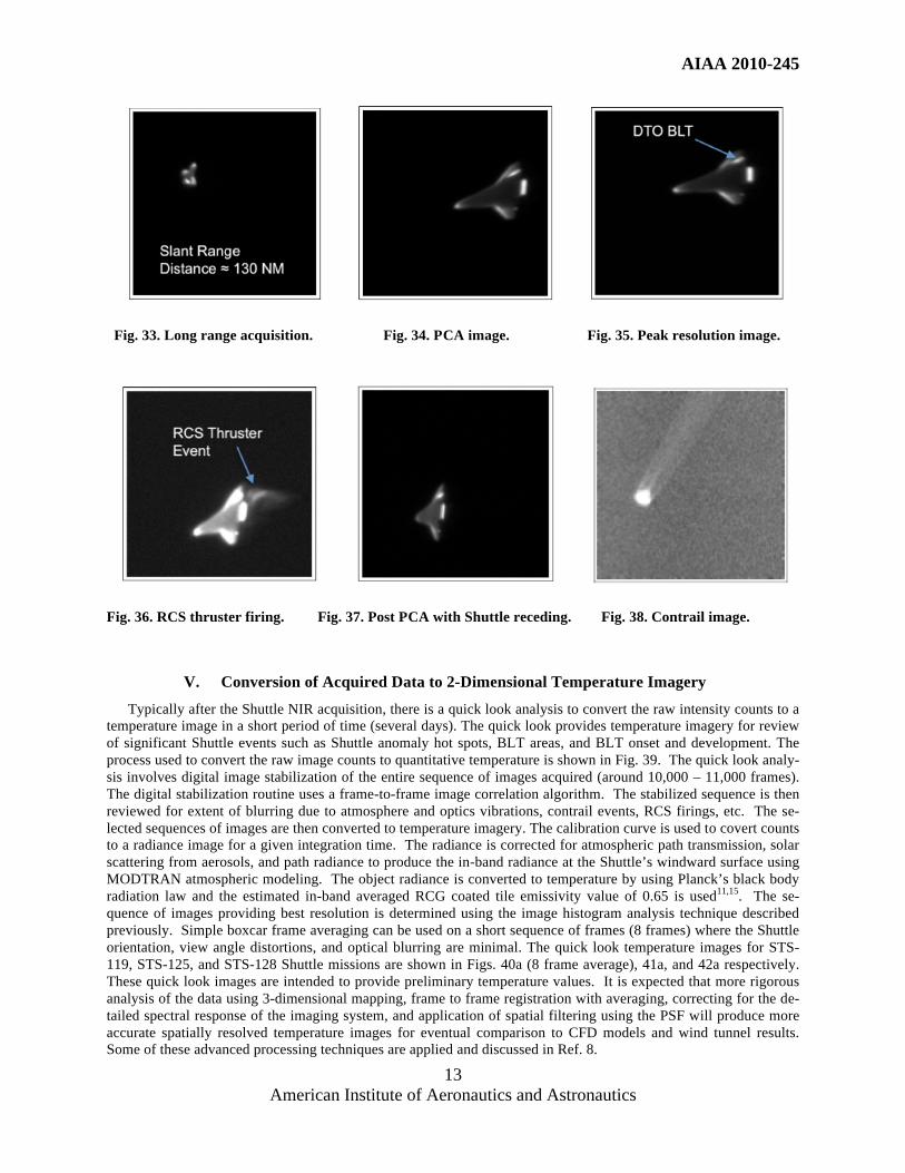
manually, in fine steps and in real time during acquisition. An example long range acquisition image (slant range
distance approximately 130 NM), the image at PCA, the maximum resolution image, RCS thruster firings, the post
PCA image showing the Shuttle moving away from Cast Glance, and contrail image are shown in Figs. 33, 34, 35,
36, 37 and 38 respectively. Figs. 34, 35 and 37 show the DTO BLT imaged successfully.
Fig. 29. STS-128 Cast Glance and Shuttle distance. Fig. 30. NIR camera integration times.
Fig. 31. Estimate of Shuttle pixel resolution. Fig. 32. Number of saturated pixels.
AIAA 2010-245
American Institute of Aeronautics and Astronautics
13
Fig. 33. Long range acquisition. Fig. 34. PCA image. Fig. 35. Peak resolution image.
Fig. 36. RCS thruster firing. Fig. 37. Post PCA with Shuttle receding. Fig. 38. Contrail image.
V. Conversion of Acquired Data to 2-Dimensional Temperature Imagery
Typically after the Shuttle NIR acquisition, there is a quick look analysis to convert the raw intensity counts to a
temperature image in a short period of time (several days). The quick look provides temperature imagery for review
of significant Shuttle events such as Shuttle anomaly hot spots, BLT areas, and BLT onset and development. The
process used to convert the raw image counts to quantitative temperature is shown in Fig. 39. The quick look analy-
sis involves digital image stabilization of the entire sequence of images acquired (around 10,000 – 11,000 frames).
The digital stabilization routine uses a frame-to-frame image correlation algorithm. The stabilized sequence is then
reviewed for extent of blurring due to atmosphere and optics vibrations, contrail events, RCS firings, etc. The se-
lected sequences of images are then converted to temperature imagery. The calibration curve is used to covert counts
to a radiance image for a given integration time. The radiance is corrected for atmospheric path transmission, solar
scattering from aerosols, and path radiance to produce the in-band radiance at the Shuttle’s windward surface using
MODTRAN atmospheric modeling. The object radiance is converted to temperature by using Planck’s black body
radiation law and the estimated in-band averaged RCG coated tile emissivity value of 0.65 is used11,15
. The se-
quence of images providing best resolution is determined using the image histogram analysis technique described
previously. Simple boxcar frame averaging can be used on a short sequence of frames (8 frames) where the Shuttle
orientation, view angle distortions, and optical blurring are minimal. The quick look temperature images for STS-
119, STS-125, and STS-128 Shuttle missions are shown in Figs. 40a (8 frame average), 41a, and 42a respectively.
These quick look images are intended to provide preliminary temperature values. It is expected that more rigorous
analysis of the data using 3-dimensional mapping, frame to frame registration with averaging, correcting for the de-
tailed spectral response of the imaging system, and application of spatial filtering using the PSF will produce more
accurate spatially resolved temperature images for eventual comparison to CFD models and wind tunnel results.
Some of these advanced processing techniques are applied and discussed in Ref. 8.

AIAA 2010-245
American Institute of Aeronautics and Astronautics
14
Fig. 39. Conversion of raw intensity imagery to quick look temperature.
Fig. 40. STS-119 temperature image with centerline temperature plot and thermocouple comparison.
Fig. 41. STS-125 temperature image with centerline temperature plot and thermocouple comparison.
Fig. 42. STS-128 temperature image with centerline temperature plot and thermocouple comparison.

AIAA 2010-245
American Institute of Aeronautics and Astronautics
15
VI. Quick Look Temperature Measurements Compared to Thermocouple Values
The quick look thermal imagery obtained from the HYTHIRM missions is compared to the Shuttle’s onboard
thermocouples values for STS-119, STS-125, and STS-128 in Figs. 40b, 41b and 42b respectively. The comparisons
were performed on the thermocouples located along the centerline. The actual locations of the thermocouples are in
3-dimensional space due to the curvature of the Shuttles windward surface. Using the centerline simplifies location
of the thermocouples along 1-dimension. The averaged magnitude difference and averaged ºF percent difference
error were 172ºF and 14.1 percent respectively. It is important to note the percent errors are greater when measuring
lower temperatures (around 1100ºF) due to the spectral limitation of the NIR sensor. Omitting thermocouple tem-
peratures less than 1100ºF reduces the averaged magnitude difference and averaged ºF percent difference error to
119ºF and 8.5 percent respectively. These values are feasible for the quick look calculations. There are uncertainties
associated with the thermocouples that must be quantified for a proper comparison. Typically, the thermocouple
offset error is 20 ºF cooler than the actual surface with uncertainties around +/- 20ºF2. However, the OV-104 data
seems to exhibit some currently unexplained behavior as seen in Fig. 41b where the centerline thermocouple values
were scattered with some temperature differences of over 200ºF. This is not expected over a region of laminar flow
(temperatures should be uniformly decreasing spatially from nose to aft) and suggests some additional thermocouple
offset errors that have not been accounted for. This behavior is currently under investigation. It is expected that a
more sophisticated mapping of the 2-dimensional image to the actual 3-dimensional surface of the Shuttle’s wind-
ward surface will allow for a more accurate determination of the location of the thermocouple in relation to the
temperature image and this will help to reduce errors especially in areas of large thermal gradients (note thermocou-
ple #9468 in Fig. 40b). Also the spectral response of the NIR system was not used to produce the quick look
images. The planned determination and application of the detailed spectral response of the imaging system will help
to reduce errors. Solar reflection from the RCG coated black tiles is not expected to be significant, but may contrib-
ute. The quick look examination of the NIR thermal image data shows low noise within the desired temperature
range, while providing global coverage across the orbiter windward surface. It is expected that future efforts8 im-
plementing the 2-dimensional to 3-dimensional mapping, applying the spectral response, application of spatial
filtering using the PSF, and applying advanced image registration with frame averaging will improve the spatial
accuracy of the HYTHIRM generated spatially resolved temperature values with some improvement of the already
low noise values. After the additional processing, these temperature values can be used to verify computation mod-
els16
.
VII. Summary
Implementation of the digital NIR camera system has resulted in NIR imagery with improved dynamic range, in-
stantaneous field of view, and signal to noise. Minimal saturation was obtained for STS-119, STS-125, and STS-
128 thermal observations. The acquired data were able to image the BLT DTO for both STS-119 and STS-128. In
addition an ABLT of unknown origin was imaged for STS-119. Also the quality of the NIR imagery allowed for
detailed analysis of the collected data using an image histogram analysis method. The image histogram analysis
technique determined which image or frame provided maximum pixels on target based on a combination of PCA
and optimal viewing angle (normal incidence to the Shuttle’s windward surface) and also was able to detect RCS
firings. The quick look temperature images provided good agreement, to within 8.5 percent, of the Shuttle’s on-
board thermocouples for temperature values above 1,100 ºF. It is important to note the errors, both random and
systematic, due to the onboard thermocouples needs to be quantified. Lastly, it is expected that implementing the 2-
dimensional to 3-dimensional mapping, applying the spectral response of the optics, spatial filtering to de-blur the
image, and applying advanced image registration with frame averaging will improve the utility of the HYTHIRM
generated temperature imagery.
Acknowledgments The authors would like to acknowledge the fact that without the assistance of the following organizations and
individuals the ambitious work performed under the HYTHIRM project would not have been possible. The
authors gratefully acknowledge their contributions and behind-the- scenes work:
• Richard Schwartz, Karen Berger, Scott Splinter, Tom Spisz, Harry Verstynen, Kamran Daryabeigi, Mike
Alexander, Scott Berry, Arna Majcher, Andrew McCrea, Paul Krasa, and the rest of the HYTHIRM team,
NASA LaRC for perfect mission execution.

AIAA 2010-245
American Institute of Aeronautics and Astronautics
16
• Dan Hand, CSC/ISTEF for technical support pertaining to calibration and instrumentation hard-
ware/software upgrades.
• Robbie Kerns, LaRC Space Operations Program Office for advocacy and support.
• Jim Hochstetler for calibration logistical support at NAS Corpus Christi, Texas.
• Ron Dantowitz and Marek Kozubal, MARS Personnel, Clay Center Observatory Dexter Southfield
Schools.
• Mike Hernandez, Keena Odeghe, and the entire Cast Glance Personnel, Naval Air Warfare Center - Weap-
ons Division US Navy for extreme dedication and ultimately mission execution.
• Stephen Tedford, Commanding Officer, and the entire VX-30 “Bloodhounds” squadron and maintenance
personnel for getting HYTHIRM to the right spot in the sky.
• Chuck Campbell and Brian Anderson, NASA JSC for technical consultation and coordination related to the
BLT Flight Experiment
• Jennifer Gruber, Mark McDonald and the Flight Dynamics Group, NASA JSC for providing invaluable
mission planning support
• John Shannon and LeRoy Cain, JSC Shuttle Program for advocacy and support.
• Tim Orham and the entire Spaceflight Meteorological Group at NASA JSC for their weather forecasting
capabilities.
• Nicole Lamotte, Olman Carvajal, Peter Jang, and Susan Kwong, Boeing/USA for decent flight trajectories
and consultation pertaining to navigation, aerodynamics and the Shuttle instrumentation database.
• Michael Werner and Don Rudy, The Aerospace Corporation for mission planning and initial radiance
model development and application.
• Don Noah, Terri Murphy, Brenda Eliason and Tracy Calhoun, NASA JSC for insight into the Shuttle on-
orbit imaging process and advocacy.
• Mike Kelly and Kwamee Osei-Wusu, Applied Physics Laboratory for technical expertise and image proc-
essing; Jim Kouroupis and John Watson, Applied Physics Laboratory for asset identification and technical
consultation.
• Dan Dexter and the entire CEL imaging lab personnel, NASA JSC for graphical-based mission planning.
• Angelo Guastaferro, NIA for project management consultation, leadership and wisdom.
• Richard Wheless, NCI Information Systems and Laura Bass, SAIC for assistance in illustration preparation
for proposals, briefings and this manuscript.
• Bob Blanchard, The George Washington University for re-entry imaging inspiration and technical consulta-
tion.
• Andrew McCrea, Test Environment Visualization and Support, ATK Space Division, NASA Langley Re-
search Center.
• Bill Wood, NASA LaRC for contributions to radiance modeling and CFD support.
References
1 Horvath, T. J., Tomek, D. M., Berger, K. T., Splinter, S. C, Zalameda, J. N., Krasa, P. W., Tack, S., Schwartz, R. J., Gibson, D.
M., and Tietjen A. B., “The HYTHIRM Project: Flight Thermography of the Space Shuttle during Hypersonic Re-
entry," AIAA Paper 2010-241, Jan. 2010. 2 Anderson, B., Campbell, C., Kinder, J., and Saucedo, L., “Boundary Layer Transition Flight Experiment Overview and In-Situ
Measurements,” AIAA-2010-420, Jan. 2010. 3 Tack, S., Tomek, D. M., Horvath, T. J., Verstynen, H. A., and Shea, E. J., “Cast Glance Near Infrared Imaging Observations of
the Space Shuttle during Hypersonic Re-entry," AIAA Paper 2010-243, Jan. 2010. 4 Horvath, T., Berry, S., Alter, S., Blanchard, R., Schwartz, R., Ross, M., and Tack, S., “Shuttle Entry Imaging Using Infrared
Thermography,” AIAA-2007-4267, June 2007. 5 Berry, S., Horvath, T., Schwartz, R., Ross, M., Campbell, C., and Anderson, B., “IR Imaging of Boundary Layer Transition
Flight Experiments,” AIAA-2008-4026, June 2008. 6 Ross, M., Werner, M., Mazuk, S., Blanchard, R., Horvath, T., Berry, S., Wood, W., and Schwartz, R., “Infrared Imagery of the
Space Shuttle at Hypersonic Entry Conditions,” AIAA-2008-0636, 46th AIAA Aerospace Sciences Meeting and Exhibit, Reno,
NV, Jan. 7-10, 2008.

AIAA 2010-245
American Institute of Aeronautics and Astronautics
17
7 Horvath, T., Berry, S., Splinter, S., Daryabeigi, K., Wood, W., Schwartz, R., and Ross, M., “Assessment and Mission Planning
Capability For Quantitative Aerothermodynamics Flight Measurements Using Remote Imaging,” AIAA-2008-4022, June 2008. 8 Gibson, D. M., Spisz, T. S., Taylor, J. C., Zalameda, J. N., Horvath, T. J., Tomek, D. M., Tietjen, A. B., Tack, S., and Bush, B.
C., “HYTHIRM Radiance Modeling and Image Analyses in Support of STS-119, STS-125, and STS-128 Space Shuttle Hyper-
sonic Re-entries," AIAA Paper 2010-244, Jan. 2010. 9 A. Berk, L.S. Bernstein, and D.C. Robertson, “MODTRAN: A moderate resolution model for LOWTRAN7”, Report GL-TR-
89-0122, Air Force Geophysics Lab., Bedford, MA, 1989. 10
Splinter, S., Daryabeigi, K., Horvath, T., Mercer, C.D., Ghanbari, C. M., Ross, M. N., Tietjen, A., B., and Schwartz, R., J.,
“Solar Tower Experiments for Radiometric Calibration and Validation of Infrared Imaging Assets and Analysis Tools for Entry
Aero-Heating Measurements,” AIAA-2008-4025, June 2008. 11
Tietjen, A. B. and Hand, D. “Calibration and Data Analysis Summary Report-Hythirm Solar Tower Test," HYTHIRM Inter-
nal Report, Sept. 2008. 12
Rybicki G. B. and Lightman, A. P., “Radiative Processes in Astrophysics, New York: John Wiley and Sons, ISBN 0-471-
82759-2, 1979. 13
Hanisch, R. J., Farris, A., Greisen, E. W., Pence, W. D., Schlesinger, B. M., Teuben, P. J., Thompson, R. W., and Warnock,
A., Definition of Flexible Image Transport (FITS), Astronomy & Astrophysics, 376, 359-380, 2001. 14
Tietjen, A. B. and Hand, D. “Calibration and Data Analysis Summary Report-Hythirm STS-119, STS-125 and STS-128,"
HYTHIRM Internal Report, Dec. 2009. 15
Bouslog, S. A. and Cunnington, G. R., “Emittance Measurements of RCG Coated Shuttle Tiles”, AIAA Paper 92-0851, Jan.
1992. 16
Wood, W. A., Kleb, W. L., Tang, C. Y., Palmer, G. E., Hyatt, A. J., Wise, A. J., and McCloud, P. L., “Comparison of CFD
Predictions with Shuttle Global Flight Thermal Imagery and Discrete Surface Measurements," AIAA Paper 2010-454, Jan. 2010.