4.5 penstock and valves the penstock is a pipe that carries water
TRANSCRIPT

4.5 Penstock and Valves
The penstock is a pipe that carries water from the intake to the tur
bine. Most microhydropower systems will include some type of penstock.
Depending on the site characteristics, the penstock length may range from a
few feet for manmade structures to several hundred feet for some run-of-the
stream sites. The exception is the manmade structure with an open flume
(Figure 2-12). This type of site has no penstock. Developers with an open
flume leading to the turbine can proceed to the next section. This section
discusses location, design, and installation of the penstock and its
associated valves.
If you have received a penstock recommendation from the turbine manu
facturer, you should contact suppliers to obtain pipe specification and
pricing information. If you plan to follow the turbine manufacturer1s
recommendation, you should review the contents of this section before
ordering the pipe in order to facilitate making a design layout of the
penstock and to make sure that you have considered all materials and costs.
4.5.1 Locating the Penstock
Run-of-the-stream developers determined a preliminary routing for the
penstock in Section 3.4 Manmade sources generally do not allow much lati
tude in penstock routing. The developer using an existing dam has the
option of a siphon penstock (Figure 2-13) or a power canal routed around
the dam (see Subsection 4.4.3). Any modification to an existing dam is
beyond the scope of this handbook.
In general, the optimum penstock is as short, straight, and steep as
practical and has a continuous downward gradient. A power canal can be
constructed to divert the water to give the best penstock alignment, (see
Subsection 4.4.2). These characteristics will minimize construction costs
and friction loss.
4.5-1
The following are some of the major factors that must be considered in
selecting a penstock route:
• Accessibility. The route should be accessible to personnel and
equipment required for pipe installation, inspection, and main
tenance. In those areas where equipment access is difficult or
impossible, installation and maintenance must be performed
manually.
Soil Conditions. Soils along the pipeline should be examined to
identify rock outcroppings, soft or unstable soils, or other
characteristics that would interfere with penstock installation
or damage the penstock.
Natural or Man-Made Obstructions. These include trees, roadways,
buildings, stream crossings, and other features that require
special care.
• Gradient. The penstock is best routed to take advantage of the
natural downward gradient. If the line cannot be located so as
to have a constant downward gradient, an air relief valve or
equivalent device is required at every local high point, and a
drain valve is required at every local low point.
Above- or Below-Ground Installation. A buried penstock has
certain advantages over an above-ground installation. Anchoring
and supporting the pipe are simplified, ultraviolet radiation
effects on PVC pipe are eliminated, and the effects of weather
(thermal expansion, freezing) are reduced. In addition, physical
damage to the pipe from falling rocks and trees or other sources
is also prevented. On the other hand, an above-ground pipe will
have a lower construction cost, may allow for more direct routing
(fewer bends), and is readily accessible for inspection or repair.
Another alternative is to have a combination of above- and below
ground installation.
4.5-2

4.5.2 Design Layout
To work with the penstock section, you will find a sketch of the pro
posed penstock routing helpful. In Subsection 3.4, the routing was sur
veyed. Take the information from that survey and on a sheet of graph paper
sketch out the routing. Figure 4.5-1 is an example of such a sketch. You
are encouraged to make a similar sketch of your site as well as an eleva
tion view to confirm grades and elevations.
The sketch is helpful in identifying the number of elbows needed, in
determining where the penstock will be above or below ground, and in
locating anchors and thrus~ blocks (Subsection 4.5.5), etc. The sketch
will also be helpful in the rest of this section for such items as estimat
ing the cost of outside help, additional equipment, total material
requirements, etc.
4.5.3 Material Selection
The turbine manufacturer may have recommended a certain material for
the penstock. You may want to consider other material that might be less
expensive. The most common penstock materials include:
PVC (polyvinyl chloride)
Steel
Polyethylene
FRE (fiber reinforced epoxy)
Transite (asbestos cement).
For each of these materials, you must consider a number of factors:
Cost
Availability
4.5-3

I i ri--+-; I J...r I I 17 ~ Y , I i .......~~ .... l---l--I--ii -+--+ 1-+,
-r-I i
I"""tl"'"
\
I ""'N... I , ,
-+- I I No-.
I -r :
I I ' I ! I I : II I
Figure 4.5-1. Sketch of proposed penstock routing.
4.5'-4

Physical properties (friction, strength, chemistry)
Joining methods and installation limitations.
These factors are greatly influenced by a number of local and special
conditions that are beyond the scope of this handbook. Certain
observations; however, are in order.
Material costs vary with season, general economy, raw material
surpluses or shortages, location, and other factors.
In some cases, used pipe materials may be locally available. Their
use can reduce material costs, provided that the pipe is in satisfactory
condition. You should attempt to establish the history of the pipe (length
of service, material carried, maximum pressures) as well as to evaluate the
uniformity of dimensions and wall thicknesses. Visual inspection of the
stockpiled pipe is also recommended.
Material availability relates to manufacturing, marketing, and local
economic demand. Certain materials are available only in specific size
ranges. The head and flow conditions encountered will dictate the physical
properties required in the material to be used and will thus influence the
cost.
Each material alternative is governed by specific joining and installa
tion requirements. Joining methods that require special skills or equipment
will tend to increase construction costs. In addition, certain materials
are not recommended for above-ground installation. In most instances, and
especially for above-ground installations, some form of restrained joint
will be required. Restrained joints include welding, concreting, or flang
ing of pipe to prevent joint pUllout when the penstock is pressurized.
4.5-5

4.5.4 Penstock Sizing
A satisfactory penstock diameter depends on three factors:
Energy (head) losses due to friction between the water flowing in
the pipe and the inside pipe wall
Pressure limitations of the pipe as a function of wall thickness
Cost of the pipe and installation.
For a given flow rate, as the pipe diameter decreases the velocity of
the water must increase, and the corresponding energy loss increases. This
occurs because friction is a function of velocity. As velocity increases,
friction increases. On the other hand, a larger pipe diameter would mean a
decrease in velocity and a corresponding decrease in friction (head loss).
The cost of the pipe however, increases drastically with the increase in
size. The procedure presented here will help you balance energy loss with
pipe size, material, and wall thickness. A velocity of 4 fps is recommended
for the initial penstock design. Once the proper pipe size is selected,
the material and installation cost can be evaluated to select the best buy.
The energy losses associated with friction can be expressed directly
as feet of head loss.
EXAMPLE: Assume that a site has a measured head of 112 feet and that
the developer calculates the energy loss in the penstock system as
8.6 feet. The actual head available to produce energy is not 112 feet
but 103.4 feet (112 - 8.6).
Friction losses in the penstock system represent energy that is not
available for power generation.
4.5.4.1 Selecting Pipe Diameter. The first requirement for sizing a
penstock is to select the proper pipe diameter, using the design flow from
Subsection 4.3. Figures 4.5-2 and 4.5-3 are graphs to help in making this
4.5-6

~
I-(l) a. a.-0 .....-0 0 T""
.... (l) a. ..... ~ -rJ) rJ)
0
"0 co (l)
I
0 T""
0..... ~ T""
~ T""
0..... ,.... ci
T""
ci o..... T""
o ci
"
1.0
0.1
-- Pipe diameter
4 6 8 10
...... ......
" ...... ......
"
...... ......
"'"'
"'..........
24
1p --------------~----------------~-----------~
0.1 to 1.0 1.0 to 10 Flow (cfs)
INEL 2 4162
Figure 4.5-2. Pipe diameter selection graph.
4.5-7
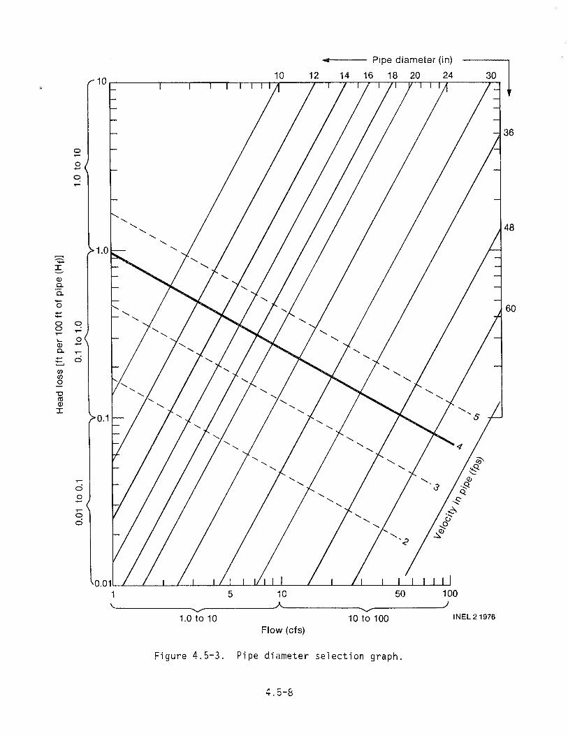
10 12 14 16 18 20 24 10r-------r---,,--r-,,-r""-.----,--.-.~_,_._n--~1T"'r__
... Pipe diameter (in) ~o
~-I -Q) a. a.-0
'+-0 0 . ..... Q) a.
:::.(/) (/) 0
u ctl Q)
I
o . o-
1.0
~ T"""
0-T"""
c:i
c:i o-
T"""
o c:i
5 10 50 100
~~--------------~--------------~--------------~-------------)1.0to10 10to100 INEL21976
Flow (cfs)
Figure 4.5-3. Pipe diameter selection graph.
4.5-8
60

selection. A range of flow values is shown at the bottom of each graph.
If the design flow is between 0.1 cfs to 10.0 cfs, use the first graph, and
if it is from 10.1 cfs to 100 cfs, use the second graph. Consult the
manufacturer if the design flow is more than 100 cfs.
1. On the appropriate graph, find your design flow.
NOTE: The graph is on log paper. The range of flow values
is marked with brackets (i .e., 0.1 cfs to 1.0 cfs). As
examples, flow readings of 0.32 cfs and 7.2 cfs are shown
with small arrows at the bottom of the graph on Figure 4.5-2.
2. Draw a vertical line up from the design flow value to the recom
mended velocity line (the 4 fps line running diagonally line from
the upper left corner to right center). The intersect point with
4 fps will be bracketed by two pipe diameter lines (diagonal lines
running from the upper right to the lower left). Either of the
bracketing penstock sizes can be used, but it is recommended that
the larger size be ,selected to keep velocity (and head loss) low.
Lower velocity will also result in less water hammer. A penstock
head loss of 5 to 10% of the pool-to-pool head can be a reasonable
design starting point.
The actual velocity of water in the penstock will be the point at
which the vertical line representing flow intersects the selected
pipe size line and will probably be slightly lower than 4 fps if
the larger pipe size is chosen.
EXAMPLE: Referring to Figure 4.5-4, assume a design flow of
4 cfs. From 4 cfs (Point 1), draw a vertical line up to the
4 fps line (Paint 2). Select the larger of the pipes--in
this case, the 14-inch diameter pipe (Point 3). At Point 3,
the velocity of 4 cfs in the 14-inch pipe can be estimated
as 3.7 fps (Point 3 is approximately 0.7 of the way between
3 fps and 4 fps).
4.5-9

:::::: ;. Q) 0. 0.-0 +-'-0 0.... .... Q)
:=..-0.
en en 0
"0 ctS Q)
::c
0.1 0.5 1 10 Flow (cfs)
INEL 2 1362
Figure 4.5-4. Pipe diameter selection example.
-- Pipe diameter
4 6 8 10
"'"'
"'"
1.0
""
0.1
20
24
O.01~~--~--~~~--~~~~~--~~~--~~~~~~~

3. From the pipe size intersect (Point 3), draw a horizontal line to
the left side of the graph. The numbers on the left side of the
graph represent the head loss per 100 feet of pipe length.
EXAMPLE: From Point 3, draw a line to the left side of the
graph (Point 4). At Point 4, read the head loss factor as
0.34 ft per 100 feet of pipe. The actual loss depends on
pipe material.
4. Record the penstock diameter and actual velocity (Point 3 in the
example) and the friction loss factor (Point 4).
4.5.4.2 Selecting Pipe Material. It is now time to consider various
pipe material alternatives so that the actual friction losses can be calcu
lated. Virtually any of the materials previously discussed can be used,
but experience indicates that two materials, PVC and steel, stand out as
the most likely choices for the greatest number of installations. As pre
viously stated, local and site specific factors can influence material
options and must be considered.
The selection of pipe material and pipe wall thickness depends on the
pressure that the pipe will experience. There are two types of pressure to
be considered:
Static pressure, which is the pressure at the bottom of the pipe
when the pipe is filled and the water is not flowing.
Pressure waves, which are caused when the amount of water flowing
is suddenly changed, as by opening or closing a valve.
Static pressure depends on the head in the penstock. Pressure waves
depend on how fast the flow changes in the penstock.
To aid in determining the design pressure rating of the penstock and
selecting the suitable pipe material, Table 4.5-1 lists the wall thickness
(t )' pressure rating CPR)' and surge allowance factor (SA) for several wsizes of commonly available pipe materials.
4.5-11

TABLE 4.5-1. PIPING ALTERNATIVES
.j:"
IJ1 I
N
INEL 21975
Pipe size- 4 in. 6 in. Pipe material t tw PR SA tw PR SA
0.24 1400 57 0.28 1200 56
Steel
0.11 100 12 0.16 100 12
PVC (polyvinyl 0.17 chloride)
160 15 0.25 160 15
0.26 250 18 0.39 250 18
0.26E 100 9 0.39 100 9
PE (polyethylene) 0.41 160 11 0.60 160 11
0.62 250 13 0.91 250 13
0.32 100 41 0.46 100 41
A-C (transite-
asbestos 0.41 150 44 0.53 150 43
cement) 0.41 200 44 0.66 200 45
0.07 225 17 1.11 250 16
FRP (fiber reinforced epoxy)
----- , ._--
a. Above 24 inches, see manufacturer.
Bin. 10 in.
tw PR SA tw PR SA tw
0.25 800 54 0.25 640 52 0.25
0.32 1100 56 0.37 1030 55 1.38
0.41
0.21 100 12 0.26 100 12 0.31
0.33 160 15 0.41 160 15 0.49
0.51 250 18 0.63 250 18 0.75
0.51 100 9 0.63 100 9 0.75
0.78 160 11 0.98 160 11 1.16
1.18 250 13 1.47 250 13 1.75
0.56 100 40 0.62 100 39 0.72
0.63 150 41 0.83 150 42 0.96
0.81 200 45 1.02 200 45 1.18
0.14 225 16 0.18 225 15 0.21
12 in. 14 in. 16 in. 18in. 20in. 24 in.a
PR SA tw PR SA tw PR SA tw PR SA tw PR SA tw PR SA
540 51 0.25 490 50 0.25 430 49 0.25 380 4B 0.25 340 47 0.25 280 45
890 54 0.38 810 54 0.38 710 52 0.38 630 52 0.38 570 51 0.38 470
1000 55 0.44 970 55 0.50 990 55 0.50 880 54 0.50 790 53 0.50 660
0.59 950 54 0.69 940 54
100 12
PVC pressure pipe 160 15 not available
250 18
100 9 0.82 100 9 0.94 100 9 1.06 100 9 1.12 100 9 1.41 100 9
160 11 1.27 160 11 1.46 160 11 1.64 160 11 1.81 160 11
250 13 1.92 250 13
100 38 0.74 100 38 0.83 100 37 0.95 100 37 1.06 100 37 1.24 100
150 41 1.11 150 41 1.23 150 41 1.47 150 42 1.64 150 42 1.98 150
200 44 1.38 200 44 1.57 200 44 2.09 200 45 1.98 200 45 2.81 200 45
225 15 0.26 225 15 0.29 225 15

The procedure for determining penstock pressure rating (design
pressure rating) is as follows:
1. Using the total design head determined earlier in Subsection 4.3,
establish the static head on the penstock. From the relationship
developed in Subsection 3.4.1 (1 foot of heat = 0.433 psi), the
static pressure can be determined by using Equation (4.5-1).
S = 0.433 x h (4.5-1)
where
S = static pressure in psi
0.433 = converts feet to psi
h = design head in feet.
EXAMPLE: Assume that the head in Figure 4.5-1 is 325 feet.
Use Equation (4.5-1) to find the static pressure in the
penstock at the turbine.
S = 0.433 x h
S = 0.433 x 325
S = 141 psi.
2. Using the penstock diameter previously established, select from
Table 4.5-1 one (or more) potential pipe materials and select the
t ' PR, and SA factors for these materials. w
NOTE: Select these factors for a pressure rating value CPR)
greater than the static pressure determined in Step 1 above. If
the head is large, the pressure value should be significantly
larger than the static pressure.
4.5-13

EXAMPLE: Assume a 14-inch pipe and static pressure of
141 psi. Select pipe materials from Table 4.5-1.
Steel: All have a PR greater than 141 psi.
PVC: Not available.
PE: The PR is above 141 psi for both 1.27 and 1.92 t ' w but only the 1.92, with a PR of 250 psi, is
significantly above 141 psi.
AC: The P is significantly above 141 psi only for theR 1.38 t ' with a PR of 200 psi.w
FRP: The 0.26 tw has a PR = 225 psi.
Therefore, consider the following pipe material and thickness:
Steel: tw = 0.25, = 490, SA = 50PR
PE: t = 1.92, = 250, S = 13 w PR A
AC: t = 1.38, PR =, 200, S = 44 w A
FRP: t = 0.26, = 225, S = 15 w PR A
3. For each pipe material selected, use Equation (4.5-2) to determine
the penstock design pressure (Pd).
(4.5-2)
where
= penstock design pressure in psi
4.5-14

S = static pressure in psi, from Equation (4.5-1)
= surge allowance factor from Table 4.5-1
v = velocity of the water in the pipe in fps, from
Figure 4.5-2 or 4.5-3.
NOTE: To use Equation (4.5-2), multiply SA and v before
adding to S.
EXAMPLE: From the previous example, S = 141 psi, and from
Figure 4.5-4, v = 3.7; use Equation (4.5-2) to find the
design pressure for the pipes to be considered.
Steel: = 141 + (50 x 3.7)Pd = 141 + 185
= 326 psiPd
PE: Pd = 141 + (13 x 3.7)
= 189 psiPd
AC: Pd = 141 + (44 x 3.7)
Pd = 303 psi
FRP: = 141 + (15 x 3.7)Pd Pd = 196 psi
4. The design pressure rating, PR, must be greater than the Pd value for the material and wall thickness selected. If it is
not, recalculate the design pressure using the next thicker wall,
or select another material.
4.5-15

EXAMPLE: From Steps 2 and 3 above, the following is known:
Steel: P = 490 ps i , P = 326 ps iR d
PE: = 250 psi, = 189 ps iPR Pd
AC: = 200 ps i , Pd = 303 ps iPR
FRP: = 225 psi, P = 196 ps iPR d
Since the PR is larger than the Pd for steel, PE, and
FRP, these materials can be used. AC, with a PR smaller
than the Pd, cannot be used in this example.
For pipe materials and wall thicknesses not included in Table 4.5-1,
you should contact the pipe supplier for the necessary information. The
data from the supplier will probably list wall thickness as (t), design
pressure as (P), and allowable surge pressure as (W).
4.5.4.3 Calculating Penstock System Head Loss. The next step is to
calculate the total penstock head loss. The total losses are a function of
both turbulence and friction.
Turbulence is caused by the intake structure and by bends and obstruc
tions in the pipe. Turbulence factors can best be considered by adding
equivalent pipe length to the overall length of the penstock to get the
adjusted length (La). This can be done by the following steps:
Multiply the number of 90 degree bends by 30 feet
Multiply the number of 45 degree bends by 15 feet
Add 15 feet for the entrance at the intake
4.5-16

• Add 100 feet for the turbine isolation valve
• Sum all the additions and add to the total penstock length.
EXAMPLE: From Figure 4.5-1:
o each 90 degree bends
5 each 45 degree bends
5 x 15 = 75 feet
Intake structure--15 feet
1 turbine isolation valve--100 feet
Total additions ~ 190 feet
The pipe length shown in Figure 4.5-1 is 336 + 150 + 328
+ 87 = 901 feet; 901 + 190 = 1,091 feet. Adjusted length
(La) = 1,091 feet
Friction losses are a function of pipe size, length, and material.
The friction effect is accounted for with the pipe material correction
factors shown in Table 4.5-2.
TABLE 4.5-2. FRICTION LOSS CORRECTION FACTOR (fc)
Pipe Material
Steel 1.16 PVC 0.77 PE 0.77 AC 0.87 FRP 0.77
To obtain the head loss due to turbulence and friction, multiply the
adjusted penstock length (La) determined above by the material correction
factor from Table 4.5-2. Multiply this number by the Hf factor previously
determined from Figure 4.5-2 or -3 and divide the result by 100. This final
number is the energy loss, in feet of head, for the flow, penstock length,
and material selected. Use Equation (4.5-4) to determine total head loss.
4.5-17
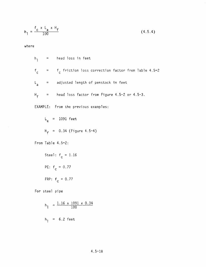
(4.5.4)
where
= head loss in feet
= fc friction loss correction factor from Table 4.5-2
= adjusted length of penstock in feet
= head loss factor from Figure 4.5-2 or 4.5-3.
EXAMPLE: From the previous examples:
La = 1091 feet
= 0.34 (Figure 4.5-4)Hf
From Table 4.5-2:
Steel: fc = 1.16
PE: f = 0.77 c
FRP: f c = 0.77
For steel pipe
1.16 x 1091 x 0.34= ---"71=00=----
hl = 6.2 feet
4.5-18

For PE and FRP
1.77 x 1091 x 0.34 hl = 100
= 2.9 feet
This loss must be subtracted from the site's available head. Since it
is a friction loss, it will not be available to produce power.
EXAMPLE: If the pool-to-pool head at the developers site is 42 feet,
the net effective head for the site is 42 - 2.9 = 39.1 feet.
You must recognize that a number of pipe diameter and material combin
ations exist for transporting the desired flow from intake to turbine. The
optimum pipe diameter tends to be a site-specific decision, and several
alternative configurations should be evaluated. The following general
suggestions may help with this evaluation.
Penstock diameter (and cost) can be reduced until the maximum
recommended velocity of 5 fps is reached. This will increase
friction losses.
Penstock friction (energy) loss can be reduced by increasing the
diameter and therefore decreasing velocity. Offsetting costs may
be realized if the reduced velocity reduces the pipe pressure
class.
Penstock friction loss can also be reduced by selecting alterna
tive pipe materials having a lower loss coefficient.
The Category 2 developer may want to compare energy loss and pipe costs
to arrive at an optimum pipe diameter.
NOTE: Higher friction in the pipe reduces the potential of freezing
in the penstock. See Subsection 4.5.7.
4.5-19

4.5.5 Valves
During the life of the generating facility, it will periodically be
necessary to stop flow to the turbine for maintenance and repair or to
dewater the penstock for repair. Also, reaction turbines use valves to
control flow and to prevent overspeed. For this reason, suitable valves or
gates at either end of the penstock should be incorporated into the
development plans.
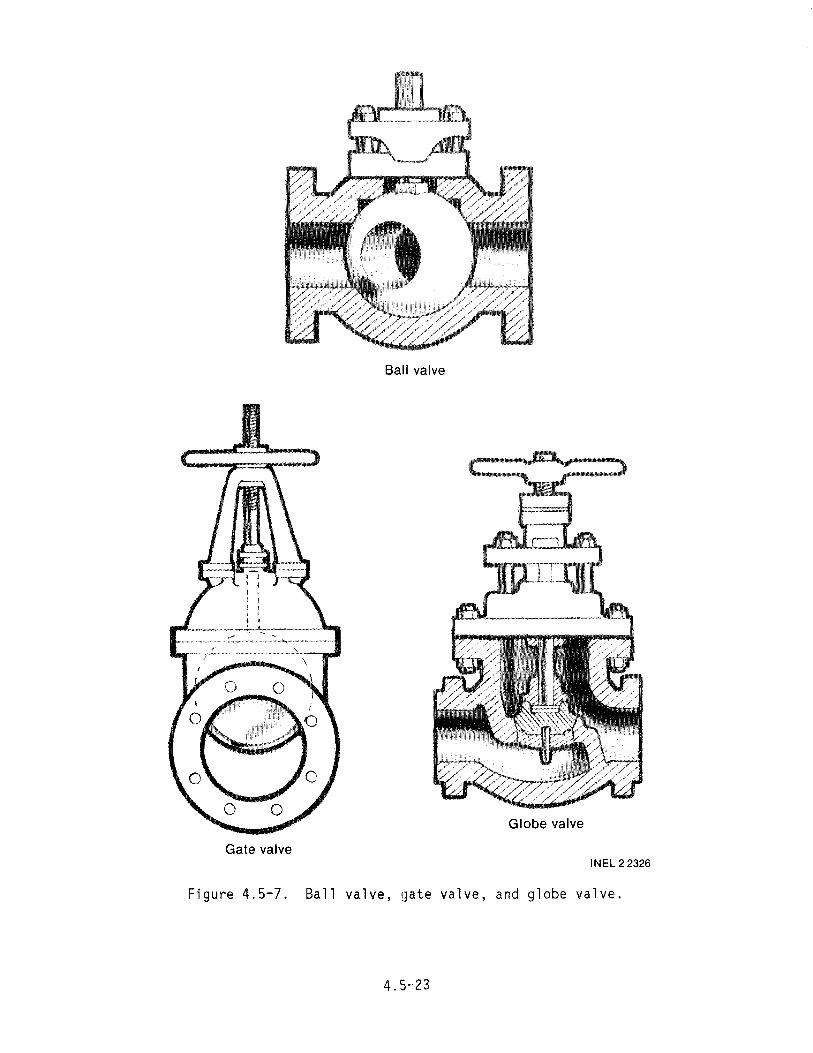
Various types of valves can be used. For gates in canals or on corru
gated metal pipe, slide gates are ideal (Figure 4.4-8). Butterfly valves
work well at either end of the penstock. Figure 4.5-5 is a photograph of a
butterfly valve body and disc, and Figures 4.5-6 and 4.5-7 present drawings
of butterfly, gate, ba 11, and globe va 1ves.
4.5.5.1 Penstock Intake. As discussed in the Intake subsection (4.4),
a slide gate or butterfly valve can be incorporated into the structure at
the intake of the penstock. The penstock inlet downstream from the valve
must be open to the atmosphere to prevent the formation of a vacuum during
penstock dewatering. This can also be a part of the inlet design, or an
air admission valve can be added. This could consist of an open vent stand
pipe with the top elevation higher than the water surface at the forebay
(Figure 4.4-13).
4.5.5.2 Penstock Upwar~_l2Be. At any point on the penstock where a
high point exists, (that is, where the pipe has an upward slope) an air
release valve should be installed. Similarly, a drain must be installed at
any low point. Use Table 4.5-3 for approximate sizing of the air valves.
TABLE 4.5-3. SIZING OF AIR VALVES
Valve Diameter . (inches)
Maximum Penstock Flow {cfs2
1 2 3
Up Up Up
to to to
4 8 15
4.5-20

Figure 4.5-5. Butterfly valve body and d~sk.
4.5.5.3 Turbine Isolation Valve. At the lower end of the penstock,
an isolation valve is required for stopping flow to the turbine. The tur
bine isolation valve should be connected (flanged) to the turbine to permit
disconnecting the turbine from the penstock. The valve could be anyone of
a number of gate valves, globe valves, ball valves, or butterfly valves.
However, the head loss is greater in a globe valve. The least expensive of
these options are the butterfly and gate valves. The valve should be the
same size as the penstock and have a pressure rating above the design
pressure previously determined for the penstock.
The butterfly valve is the most common in microhydropower use. A
significant characteristic of the butterfly valve is its relatively quick
rate of closure. Some reaction turbines use the isolation valve to prevent
turbine overspeed. To accomplish this, they take advantage of the quick
4.5-21

Gear operated
Handle Motor operated operated
INEL 2 2327
Figure 4.5-6. 8utterfly valves.
4.5-22
Ball valve
Globe valve
Gate valve INEL 2 2326
Figure 4.5-7. Ball valve, gate valve, and globe valve.
4.5,·23

closing characteristics of the butterfly valve. When this is done, some
other means must be designed into the penstock to eliminate surge pressure
on the penstock. If no method is provided to eliminate surge, care must be
taken to close the valve slowly. Providing a geared, motor-operated valve
with backup power supply and with slow closure rate will reduce the
potential for creating excessive surge pressures.
Surge pressure can create havoc with a penstock. It can cause a pipe
to jump and send a wave of pipe movement up the length of the penstock. If
the pressure is high enough, the penstock will rupture and cause other
damage or even injury.
CAUTION: The water will actually force a butterfly valve closed after
it is halfway closed; therefore, be very careful if you plan to use a handle
type actuator (Figure 4.5-6). The handle has flown out of the hand of more
than one unsuspecting operator. And, of course, a valve that is slammed
shut will create surge pressure.
Many clever and innovative systems can be worked out to prevent surge
pressure. Figure 4.5-8 is a drawing of such a system. An extension arm is
welded on to the handle of the valve. In the open position, the handle is
suspended by a solenoid hook or pin from the power house ceiling. A weight
is attached to the handle to pull the handle down when the solenoid is
released. The falling weight causes the handle to close the valve until
the water pressure begins to assist in the closure. At that point, the
shock absorber takes over and prevents the valve from slamming shut.
Another approach is to prevent the surge pressure by opening other valves
at the same time as the isolation valve is closed. Solenoid-operated valves
that fail open can be used in place of the purge valve shown in
Figure 4.5-9. When the generator loses its load and stops generating
energy, the solenoid valve opens as the isolation valve closes. The
solenoid valve should be at least half the size of the penstock.
4.5-24

Solenoid pin release
INEL 2 2353
Figure 4.5-8. System to prevent surge pressure.
powerhouse_______ Turbine isolation valve
, "I Tailrace
..~~
INEL 2 1370
Figure 4.5-9. Arrangement showing turbine bypass nyu and p,;rge yalve"
4.5-25

Another possibility with low head is a standpipe at the lower end of
the penstock. The pipe can either be opened to the atmosphere or sealed
with air in the pipe under pressure. The air in the pipe will act as a
shock absorber for the surge pressure. If the pipe is sealed, provision
should be made to check the water level in the pipe, since the air pocket
may have to be replaced periodically. The air will be absorbed into the
water over long periods of time. Also, standpipes have a tendency to freeze
in the cold months because the water is stagnant. If a standpipe is used,
heaters and insulation should be added to keep the water from freezing.
4.5.5.4 Turbine Bypass lIylI. Figure 4.5-9 shows two additional
recommendations for penstocks. To reduce the possibility of getting foreign
material into the turbine, it is advisable to make a lIyll connection off the
main penstock and have the turbine branch of the penstock above the bypass.
To keep the turbulance of the lIy" out of the turbine, place the "yll at least
10 pipe diameters above the turbine, e.g., place a 14-inch pipe 140 inches
above the turbine.
The second recommendation for the "YII is a purge valve. This would
consist of a 4- to 6-inch valve on a tee near the lower end of the bypass.
In the case of the figure, the purge valve and the blind flange on the pen
stock are housed in a partially buried 55-gallon drum cut to fit. The drum
with lid acts as a manhole and can help prevent freezing of the valve.
This valve is piped to discharge into the tailwater and serves several
functions. Among these are:
A "blowoff ll cleanout for silt or sand that has been carried down
the penstock.
• A bypass valve to maintain flow in the penstock if the turbine is
shut down (for example, to prevent freezing).
CAUTION: The water in the penstock is under pressure. The purge valve
and discharge pipe must be anchored. In addition, the discharge pipe
should be directed into the tailrace. If a reaction turbine is used,
4.5-26

the discharge should be into the tailrace pool of water below the draft
tube. The water in the pool will help to dissipate part of the energy.
You can never be too careful when dealing with a pressurized penstock.
Remember, there is more potential energy in a penstock than the electrical
energy that the generator generates, and both can be very dangerous when
not handled correctly.
Figure 4.5-10 is a photograph of a purge valve in operation.
4.5.5.5 Turbine Flow Control Valve. Control of flow to the turbine
is usually a feature of the turbine package. If the rate of flow to the
turbine is to be controlled (to control speed and generator output), this
is typically accomplished by means of wicket gates on a Francis turbine,
needle or spear valves on Pelton and Turgo turbines, and control gates on a
Figure 4.5-10. Purge valve in operation.
4.5-27

cross-flow turbine (see Figure 4.5-11). These valves and their associated
governors are integral parts of the turbine unit and are provided by the
turbine manufacturer.
Other turbines such as pumps used as turbines do not lend themselves
to flow control. The best alternative is a load diverter where a constant
flow is applied to the pump and the diverter controls the turbine speed
(see Subsection 4.8).
4.5.6 Siphon Penstock
The siphon penstock is a good option where the lift is small and no
other method is easily available to transfer the water to the turbine. If
you plan to use a siphon penstock (see Figure 2-13), the hydraulic consider
ations already discussed (velocity and friction head losses) apply. Addi
tional considerations include a means of starting the siphon. In order to
start a siphon, the penstock must be completely full of water when the lower
downstream valve is opened. For small diameter penstocks, a foot valve on
the suction end can be used. For larger diameter penstocks, some form of
automatic priming device must be used. A partial vacuum is drawn on the
high point of the penstock until the pipe is filled with water. Once the
penstock is filled, the water will start flowing to initiate the siphon
action.
The maximum theoretical height to which a siphon can raise water at
sea level is 34 feet. As a rule of thumb, the maximum practical lift a
developer should design to is 20 feet at sea level. This lift could be
even less at high elevations or when using siphons with high friction
losses. At an elevation of 5000 feet, for instance, the maximum theoretical
lift is 28 feet instead of 34 feet. With friction losses, the practical
lift will be less than 20 feet. If you feel that a siphon penstock is the
best choice for your site and you are not familiar with fluid flow calcula
tion techniques, you should seek professional help for the design.
4.5-28

Impulser turbine bucket
Spear or needle valve
Cross flow gate
Wicket gate
Fully open Nearly closed
INEL 2 2354
Figure 4.5-11. Types of turbine flow control valve.
4.5-29

In climates where the temperature occasionally drops below zero, the
exposed portion of the penstock should be protected from freezing. The
pressure at the top of the penstock is less than the atmospheric pressure
and thus raises the freezing temperature of the water. A coat of spray-on
insulation should suffice.
A rule of thumb in siphon penstock design is to keep the lift to a
minimum. In other words, go no higher than absolutely necessary to clear
the obstacle you wish to cross. This keeps the low (negative) pressure in
the penstock to a minimum. If the lift is much over 2 or 3 feet and the
penstock is large, some type of pipe stiffening is advisable. The stiffen
ing can be ribs welded along the length of the pipe. They will help prevent
the penstock from collapsing under the negative pressure.
In selecting a location for the penstock, try to locate it so that
flood waters will have the least amount of effect on the penstock. If
possible, design some type of protection around the pipe.
Some siphon penstocks have the upstream pipe flared out in a cone shape
to reduce entrance head losses and the formation of vortices, which cause
unstable turbine operation.
4.5.7 Additional Design Conside~at;ons
In addition to the specific design considerations--keeping the penstock
as straight and short as possible; maintaining a continual downward grade;
and using the proper pipe diameter, wall thickness, and material--other
items such as thrust or pressure that tends to separate the pipe, thermal
expansion, pipe span, pipe support, ultraviolet degradation, and freezing
must be considered. Whether the penstock ;s above or below ground makes a
difference on how these secondary considerations are handled.
4.5.7.1 Hydrostatic Thrust. From a safety standpoint, the most sig
nificant aspect of penstock design is the restraint of the pipe. Hydro
static thrust will cause a penstock to move (crawl) and can even separate
4.5-30

joints. The thrust is the reaction of a pressurized penstock to changes in
flow direction or to outlet nozzles. For example, a garden hose with water
flowing through a nozzle will move about freely if not held. Likewise, a
6-inch, gO-degree elbow with a 200-foot head will be subject to a force of
nearly 3,500 pounds that tends to pull the elbow away from the connecting
pipes. The following formula defines this thrust load for pipe bends.
T = 1.57 x S x 0 2 x sin e (4.5-5)p "2
where
T = thrust in pounds
S = static pressure in psi, from Equation (4.5-1).
o p 2 = pipe diameter squared (multiplied by itself), in
inches squared
esin "2 = trigonometric function, where e is the angular
change in direction; for a 45-degree bend,
sin "2e = 0.38, and for a gO-degree bend, sin e = 0.7l."2
EXAMPLE: Assume a 6-inch pipe diameter, a 200-foot head, and a
90-degree bend. Find the thrust at the bend.
First, use Equation (4.5-1) to convert head to static pressure.
S = 0.433 x h
s = 0.433 x 200
S = 86.6 psi
4.5-31
Now, From Equation (4.5-5)
T = 1.57 x S x Dp2 x sin ~
For a gO-degree bend, sin 8 0.71. Therefore,2 =
T = 1.57 x 86.6 x 6 x 6 x 0.71
T = 3475 lbs.
To resist this thrust, you will either have to use restrained jOints
:ylued PVC or welded steel) or push on or unrestrained joints with thrust
blocks. Above-ground penstocks must always use restrained joints. Buried,
unrestrained joints must include thrust blocks. A thrust block is a poured
in-place concrete mass bearing on the side of the trench to prevent movement
of the pipe. Figure 4.5-12 shows a typical thrust block.
To design a thrust block, you must determine the area (At) that
pushes against the undisturbed side of the trench. In Figure 4.5-12, it is
the height (h ) times the width (W ). Table 4.5-4 provides a basis fort t finding the area required for the thrust block.
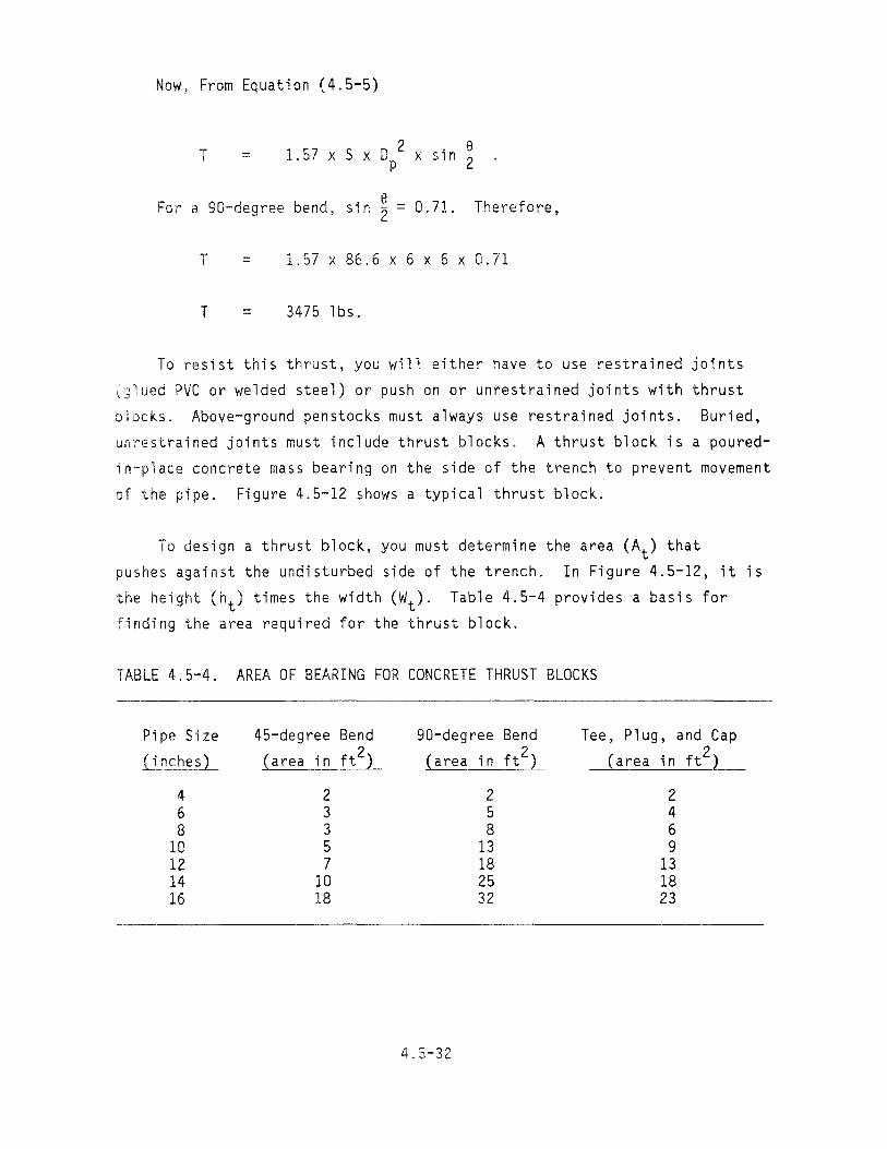
TABLE 4.5-4. AREA OF BEARING FOR CONCRETE THRUST BLOCKS
Pipe Size 45-degree Bend gO-degree Bend Tee, Plug, and Cap
(inches) (area in ft2) (area in ft 2) (area in ft2)
4 2 2 2 6 3 5 4 8 3 8 6
10 5 13 g 12 7 18 13 14 10 25 18 16 18 32 23
4.5-32

Undisturbed earth
Unrestrained joints
1> = angle change in direction or bend
Undisturbed earth
INEL 2 2316
Figure 4.5-12. Typical thrust block.
4.5-33

To allow for soil condition, the areas given in Table 4.5-4 should be
multiplied by the appropriate factor from Table 4.5-5.
EXAMPLE: Assume a 6-inch pipe with a gO-degree bend. Find the bear
ing area (At) of the thrust block when buried in sand and gravel.
From Table 4.5-4, the area is 5 ft2.
From Table 4.5-5, the multiplier is 1.33.
Therefore, At = 1.33 x 5
_ 2 At - 6.65 ft
Now that the area is known and the height is set by half the depth of
the trench, the width (Wt ) can be computed.
W =At (4.5-6)t -ht
TABLE 4.5-5. SOIL CONDITION MULTIPLIERS
Soft clay 4
Sand 2
Sand and gravel 1.33
Shale 0.4
4.5-34

where
= width of the thrust block in feet
= area of the thrust block in ft 2
= height of the thrust block, equal to half the depth of
the trench in feet
EXAMPLE: Assume that the trench is 4-feet deep; find the width of the
thrust block if the area is 6.65 ft2
h - 4 = 2 feet.t - 2
From Equation (4.5-6)
6.65-2
3.33 feet, or 3 feet 4 inches (12 x 0.33 = 4 inches)
4.5.7.2 Thermal Expansion and Contraction. The penstock will most
likely be continuously full of water at a relatively constant temperature.
Temperature changes that occur due to a drained pipe or extreme climatic
conditions will cause expansion or contraction of the pipe. PVC pipe will
expand (contract) at the rate of 0.36 inches per 100 linear feet for every
10°F temperature change. For steel, the expansion coefficient is
0.08 inches per 100 linear feet per 10°F. This means that a 1000-foot PVC
penstock will increase in length by about 4 inches for a temperature change
of 10°F. In some cases, deflection at elbows will accommodate this change.
If larger temperature changes are anticipated, care should be taken in the
routing and anchoring of pipes. (Consult the pipe supplier for assistance
in this case.)
4.5-35

I
/
4.5.7.3 Pipe Spans and Support. The maximum unsupported span for a
PVC pipe is from 6.5 feet for a 6-inch diameter pipe to 8 feet for a 12-inch
diameter pipe. For steel pipe, the maximum span should be limited to about
15 feet for the smaller diameters and 25 feet for anything over a 14-inch
pipe. The pipe should be allowed to expand and contract longitudinally
(due to temperature changes) at the supports without abrading or cutting
the pipe material. Figure 4.5-13 shows a typical concrete support saddle
for above ground piping. If the pipe is layed on the ground, assure that
the soil under the pipe is free of rock and debris and that the soil is
firmly packed to support the pipe. The sides of the pipe should be bermed
to keep surface water from eroding the soil underneath.
Inclined 2· to 3·in. band penstock bolted to column
Several layers of __ construction felt roofing paper
Concrete column
Footing buried below frost line
INEL22330
Figure 4.5-13. Typical concrete support saddle for above-ground piping.
4.5-36

4.5.7.4 Ultraviolet Degradation. PVC is susceptible to damage by
sunlight, and above-ground use of PVC pipe in areas exposed to direct sun
light is typically not recommended unless the pipe is painted or otherwise
covered. Below ground, PVC is good for 10 to 15 years.
4.5.7.5 Penstcck Anchoring. If the penstock is more than 100 feet
in length, it should be anchored. To anchor a penstock, a mass of concrete
can be poured around the pipe. Before pouring the cement, coat the pipe
with a material similar to tar and wrap with several layers of felt roofing
paper. A rule of thumb is a yard of concrete for each 12 inches of pipe
diameter; therefore, a 12-inch pipe would have a 3 ft x 3 ft x 3 ft block
of concrete for an anchor.
The primary location for the anchor is just before the penstock enters
the powerhouse (Figure 4.5-9). The anchor restricts movement of the pen
stock at the powerhouse, avoiding the possibility of the penstock separating
from the turbine and eliminating loads on the turbine casing. The installa
tion of the anchor is an important additional safety factor to prevent
penstock failure because of movement of the penstock.
For long runs of above-ground pipes on steep slopes, intermediate
anchors should be provided to reduce pipe stresses from the weight of the
pipe and water. The anchor block should be firmly attached to the slope so
that its weight will not add to that already on the pipe.
4.5.7.6 Freezing. A hydropower system does not produce energy.
Rather, it transfers energy from one form to another. If water flows down
a stream from Point A to Point B, the water has dissipated the same amount
of energy that you can recover in a turbine.
In a free stream, energy is dissipated in the form of heat. Heat is
generated by the friction of water within itself and with the stream bed.
Likewise, if the water is piped from A to B, the friction between the water
and the pipe will generate a certain amount of heat. The less the friction,
the less the heat generation, and conversely, the more the friction, the
more the heat. An old steel pipe with riveted sides has a lot of friction
4.5-37

and will very seldom have a freezing problem. PVC, on the other hand, has
a very low friction factor, and ice will usually build up in the pipe in
freezing temperatures. If your site is in the mountains or in the northern
half of the U.S. and you plan to use PVC, you should consider burying the
penstock to reduce or eliminate the freezing problem.
If for some reason flow in the penstock must be stopped in the winter,
drain the penstock or use the purge valve to keep some water flowing.
4.5.8 Design Layout
After you have decided on the type and length of penstock, make a
sketch or sketches of the system. If earthwork or concrete is involved,
calculate the volume as in Subsection 4.4.4. Be sure to include all valves
and other associated equipment required to make the system functional.
4.5-38

4.6 Powerhouse
It should be noted that not all hydropower plants will require a
powerhouse. Projects using a "bulb" turbine will have the
turbine-generator package located directly in the water. In these cases,
space should be provided only for the location of the electrical
switchgear. Other turbine units may be designed for outdoor installation
of the generator and switch gear.
The purpose of a powerhouse is to house the turbine-generator set and
electrical components. The powerhouse protects the equipment from the
elements, limits access for safety and security, and provides space to
maintain and service the mechanical and electrical equipment. The
powerhouse should be constructed to fit the equipment. Consequently, the
equipment should be selected before the powerhouse is planned. Some
powerhouse details will be supplied by the turbine-generator manufacturer.
The location of the powerhouse depends on the local site conditions.
A Category 1 developer who has sufficient head and flow may decide to
locate the powerhouse next to the load source and thus reduce the
transmission distance. Since the powerhouse is generally located adjacent
to the stream it should be located above the high water mark of the stream
or flooding will result during spring runoff. If the high water mark
results in the house being too far above the stream (so that the vertical
distance from the house to the stream is not available as head to an
impulse turbine), then the house can be set lower and a long tailrace used
so that the elevation of the floodwater at the tailrace exit is lower than
the powerhouse, as shown in Figure 4.6-1. Or, you can use a reaction
turbine with a draft tube installed as discussed in Section 4.1.6, which
will allow the turbine to be set higher and still use the head.
The physical orientation of the powerhouse should be set to keep the
penstock straight. A straight penstock is much more important than a
perpendicular powerhouse parallel to the stream. Notice the location of
the powerhouse in the sketch in Figure 4.6-1.
4.6-1

....' .."~'~'
,"-~, Big berm !
with riprap
INEL22352
Figure 4.6-1. Powerhouse installation with long tailrace.
4.6.1 Physical Features of the Powerhouse
The powerhouse must be designed to accommodate the equipment and
provide adequate room for personnel to work on it. Detailed powerhouse
requirements can only be obtained from the equipment manufacturer.
Powerhouses can be constructed of wood (Figure 4.6-2), metal
(Figure 4.6-3), or masonry depending on the availability and cost of
material. In all cases, the footings, foundation, floor slab, and
equipment pad should be constructed of concrete.
The powerhouse should include an opening or access for the penstock to
connect to the equipment and an opening for the water to exit the
powerhouse in the tailrace. Other accesses or openings may be:
• A door large enough to handle the largest single item. The
dimensions of the various components can be obtained from the
manufacturer. The door should have a lock to control access.
4.6-2

Figure 4.6-2. Wooden powerhouse.
Figure 4.6-3. Metal powerhouse.
4.6-3

Windows, louvers, and roof vents to provide good
cross-ventilation for temperature control and removal of
dampness. Since most generators are designed to operate in a
temperature range of 20 to 100°F, the number and size of
ventilation openings should be adjusted to the climate.
Conduits for electrical wires to allow the connections between
the control equipment in the powerhouse and the distribution
lines outside the powerhouse.
Floor drains to allow water from leaks, condensate, or repair and
maintenance activities to drain from the building.
• Small pipe openings for piping or tubing since some generators
may be water cooled.
The powerhouse should include other features such as lighting and
electricity. Thought should be given to how equipment can be installed and
removed. It may be worth while to incorporate a beam into the powerhouse
structure for this purpose. A temporary "AII frame structure or oversized
doors to allow a forklift to enter could accommodate equipment placement
without a beam. Figure 4.6-4 illustrates some of the typical features of
the powerhouse. The illustration shows a turbine with a draft tube. If
the turbine is an impulse turbine, the draft tube will not be included.
The draft tube must discharge below the water level. The tailrace can be
equipped with a weir to provide a pool of water for discharge of the the
draft tube. The weir can be a simple metal plate slipped into an angle
iron frame bolted to the precast concrete tailrace wall (Figure 3.9). See
Subsection 4.7 for the design and size of the tailrace.
4.6.2 Powerhouse Size and Dimensions
The powerhouse should be sized for sufficient and safe clearance
around the turbine and generator equipment. Once the size of the
turbine-generator set is known, it is recommended that the minimum
4.6-4
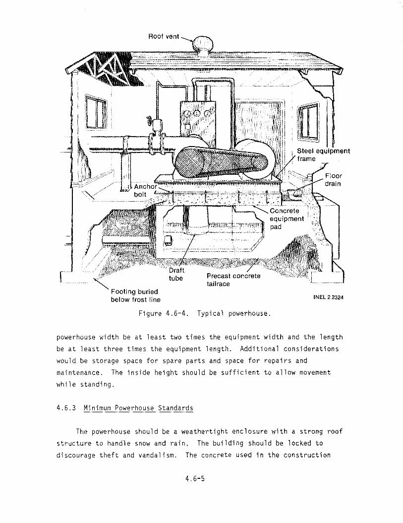
Roof vent
tailrace Footing buried below frost line
Figure 4.6-4.
powerhouse width be at least two times the equipment width and the length
be at least three times the equipment length. Additional considerations
would be storage space for spare parts and space for repairs and
maintenance. The inside height should be sufficient to allow movement
while standing.
4.6.3 Minimum Powerhouse Standards
The powerhouse should be a weathertight enclosure with a strong roof
structure to handle snow and rain. The building should be locked to
discourage theft and vandalism. The concrete used in the construction
INEL22324
Typical powerhouse.
4.6-5
should have a strength of at least 3000 psi. If ready-mix concrete is
ordered, specify the maximum strength. The floor level should be at least
1 foot above the highest maximum water level of the tailrace.
4.6.4 Location and Mounting of the Equipment
A concrete pad is necessary to mount the turbine-generator equipment
or the metal equipment frame. Equipment mounting specifications, details,
and requirements must be obtained from the equipment manufacturer to plan
for the construction of the mounting pad. The pad serves as a base for
mounting the equipment and as a mass (dead weight) to dampen the vibration
created by rotating machinery. The weight of the concrete pad should be at
least two times the weight of the equipment plus the weight of the water in
the turbine. Once the weight of the equipment and water has been
determined, the size of the pad can be determined since concrete weighs
approximately 110 pounds per cubic foot. To support any equipment, the
concrete pad should be at least six inches thick. To support heavy
equipment (more than 2000 pounds) the thickness of the pad should be
increased.
EXAMPLE: Assume that the weight of equipment plus water is 1000 pounds
Weight of concrete = 2 x 1000 = 2000 pounds
Amount of concrete = 2000 lb 110 lb/ft3 = 18 ft3
Size of 6-inch-thick pad = 18 ft 3 0.5 ft = 36 ft 2
The 36-square-foot, 6-inch-thick pad should be made to match the
length and width of the equipment. For example, if the length and width of
the equipment is basically square, then the pad should be square, or in
this case 6 x 6 feet.
Normally, the equipment pad should be placed on compacted soil or rock
and poured separately from the floor pad. Expansion joints should be
placed between the equipment pad and floor pad. This will minimize the
4.6-6

transfer of vibration into the floor pad and building. It will be
necessary to use reinforced steel bars in the equipment pad to maintain the
integrity of the concrete. The reinforcing should be at least Number 4,
located 12 inches on center each way. To aid the grounding of the
generator, the reinforcement should be welded together and a lead brought
out for a ground attachment.
The turbine package will be bolted directly to the equipment pad with
bolts. These bolts can be cast into the pad as it is poured or welded to
an angle iron cast into the concrete. The arrangement and spacing of the
bolts must match the holes drilled in the equipment frame see
Subsection 5.3.2.
Electrical panels are generally mounted on the wall, high enough from
the floor so that flooding will not cause serious damage.
4.6.5 Powerhouse Costs
The average material costs per square foot of building space for a
typical powerhouse as discussed in this section are shown in Table 4.6-1.
TABLE 4.6-1. POWERHOUSE COSTS
Costs per Square
Foot of Buildinga
Item ($)
Concrete--Includes footings, foundation, equipment pad, floor, and tailrace under powerhouse
5.00
Building Structure--Based on wood frame with metal exterior includes walls and roof
5.00
Miscellaneous--Includes door, windows, and electrical equipment
vents, 2.00
TOTAL MATERIAL COSTS PER SQUARE FOOT OF BUILDING 12.00
a. 1982 dollars.
4.6-7

A 10- x 12-foot building would contain 120 square feet of building
space. The average material costs for this powerhouse would be
120 x $12 per square foot =$1440.
If the powerhouse is constructed by a building contractor, the average
cost per square foot of building will be twice the material costs. In this
example, 120 x $24 per square foot = $2880. Costs may vary depending on
the site location and availability of local material and labor.
These costs are for the powerhouse structure and do not include costs
for the penstock, turbine-generator, control equipment, and any tailrace
beyond the powerhouse. These costs are covered in the appropriate sections.
4.6.6 Design Layout
Once the size of the powerhouse is determined, sketch the layout of
the powerhouse on a sheet of graph paper.
4.6-8

4.7 Tailrace
A tailrace is a canal or conduit that carries water from the
powerhouse to the next desired location (usually back into the stream).
4.7.1 Size of the Tailrace
The tailrace should be large enough to carry the design flow. The
velocity in the tailrace can be 2 fps. In parts of the country where fish
migration is a consideration, the velocity at the tailrace exit should be
reduced to less than 0.5 fps. Migrating fish will be attracted into the
tailrace if the velocity is too high.
For sizing the tailrace for 2 fps, refer to section on power canals,
Subsection 4.4.2.2. The power canal and tailrace will have the same
cross-sectional area. Note that the slope for the tailrace must also be
equal or greater than that of the power canal. If the reduced velocity is
needed at the stream entrance, make the end of the tailrace four times
wider. If the same depth is maintained, the velocity will be reduced to
0.5 fps.
4.7.2 Tailrace Intake
Generally, the tailrace will start below the powerhouse and is an
integral part of the powerhouse design. The width and depth is set by the
area for 2 fps. As in Figure 4.6-4, the powerhouse footings and the
tailrace intake are usually constructed from concrete. The concrete can
either be precast or poured in place. Since the equipment pad is usually
directly on top of the tailrace, the concrete must be structurally sound.
If you pour the cement yourself, be sure and use a sufficient number of
reinforcing bars. If you are not sure how to do that, then a precast
concrete box culvert purchased from a manufacturer is strongly recommended.
Figure 4.7-1 shows two types of precast concrete box culverts 11
connected together. The open top is the "u" shape type, and the closed top
is the box type. In the culvert, both ends are open; therefore, an end
4.7-1
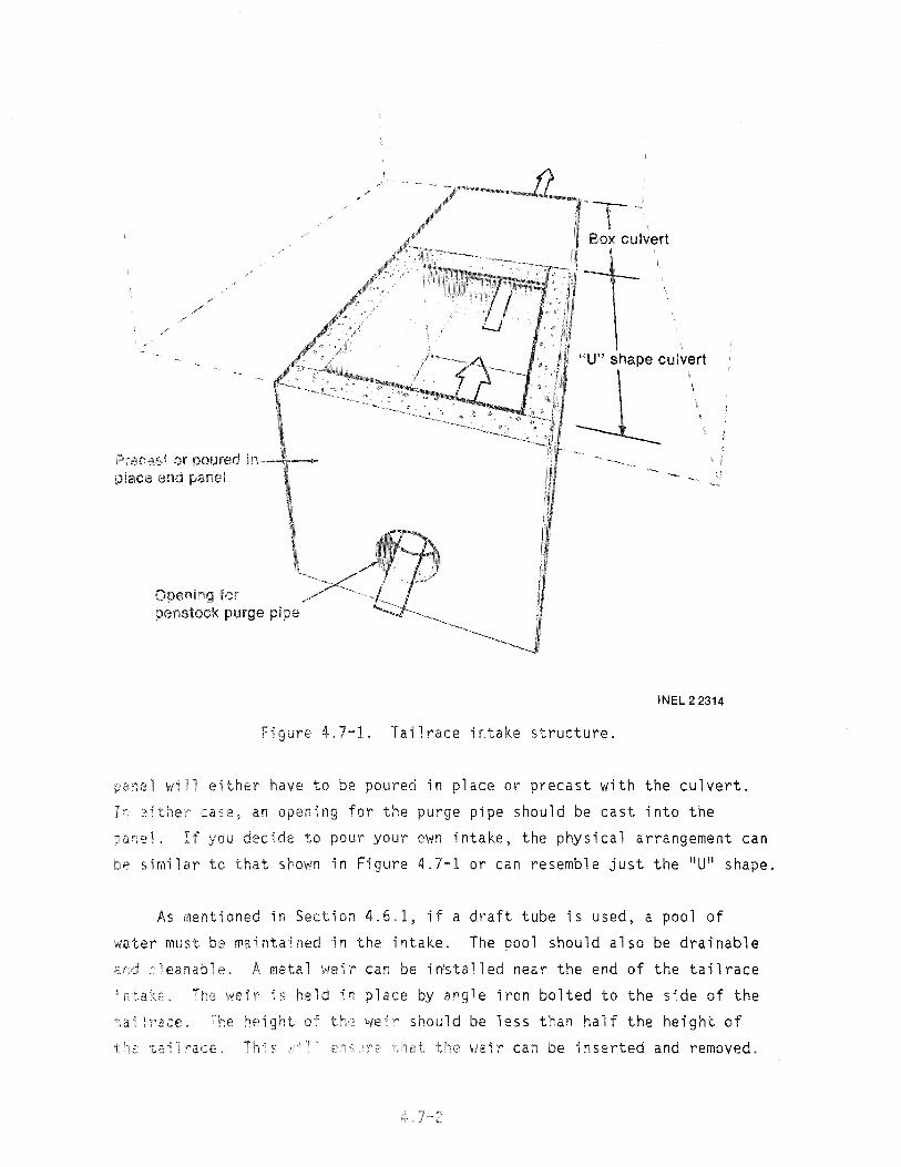
/
/' /'
Prec';;st or poured )iace end ~anel
for penstock purge pipe
Box culvert
"U" shape culvert
--L , , I
INEL 2 2314
Figure 4.7-1. Tailrace intake structure.
0a~el will either have to be poured in place or precast with the culvert.
Ir 2ither case, an opening for the purge pipe should be cast into the
~&nel. If you decide to pour your own intake, the physical arrangement can
,:":ie similar to that shown in Figure 4.7-1 or can resemble just the "U" shape.
As mentioned in Section 4.6.1, if a draft tube is used, a pool of
water must be ~aintained in the intake. The pool should also be drainable
a ~leanable. ft metal weir can be installed near the end of the tailrace ~' (.~
~.,weir held in place by angle iron bolted to the side of the
h€!i ght ..... . should be less than half the height ofO~' wed\'" ~
0'., f /; ':. r' ~';:" "- viei r can be inserted and removed.

Also, when the purge valve is opened, there will be a high-pressure stream
of water exhausted into the tailrace pool. The weir mounting must be
strong enough to withstand that force.
4.7.3 Design Considerations
The area and size of the tailrace was determined by the design flow
and the velocity. Figure 4.6-1 showed a powerhouse set lower than the
high-water mark of the stream. A long tailrace is used to lower the
elevation of the tailrace exit to a point where flood water cannot back up
the tailrace and flood the powerhouse. In this case, a berm and rip rap
will have to be constructed to protect the powerhouse and the tailrace from
flood waters. The berm should be at least 3 feet above the high water
mark. The higher the berm, the less the possibility of washing out the
powerhouse and all the equipment.
An additional advantage to a long tailrace is that the flood waters
will not raise the water level on the reaction turbine draft tube. If the
tailwater rises on a draft tube, the effective head is reduced and less
power is produced.
If the excavation involves a large volume of soil, a backhoe will be
necessary. The cost of equipment rental and operating time must be
estimated. Survey the potential location for the tailrace for rock
outcrops and other obstacles that will increase the cost of construction.
If these obstacles are too severe, an alternative location for the
powerhouse should be considered.
4.7.4 Design Layout
If the tailrace is a significant activity, sketch the tailrace on a
sheet of graph paper and estimate the material to be excavated. The cost
of the excavation can be determined in the same way as the cost of the
intake structure (Subsection 4.4.3.)
4.7-3


4.8 Generators and Electrical
A generator is an electromechanical device that converts mechanical
energy, IItorque," into electrical energy. This is accomplished by driving
a coil through magnetic lines of force and so that the coil interacts with
those lines of force to produce a voltage at the coil terminals.
The electrical distribution system for a microhydropower installation
is selected for transmitting the power developed in the generator to the
point of use.
This section is writt~n with the assumption that the developer has
some background in electricity and the terminology of electrical
construction and generator operation. Electrical and generator terminology
and the theory of a generator are discussed in Appendix A-6, which contains
the following.
A description of synchronous and induction generators and their
associated equipment
Standard voltage characteristics
Connection diagrams for a 12-lead generator to match standard
voltage characteristics
Standard nameplates and an explanation of terms
Standard generator insulation ratings and enclosures.
You may want to study Appendix A-6 on electrical theory and standard
generators before studying this subsection of the handbook.
4.8.1 Electrical Safety Considerations
The National Electrical Code (NEC) should govern the installation of
any electrical equipment from the terminals of the generator to the point
4.8-1

of consumption. The NEC is a legal document and is enforced by local
electrical inspectors. However, the NEC is also a document based on common
sense and on electrical installation practices that have been found to be
safe and to minimize the risk involved in the use of electricity. You
should comply with all requirements of the NEC. A copy of the regulation
can be obtained from bookstores or from equipment suppliers.
CAUTION: If you have questions on electrical requirements or the
connection of any piece of electrical equipment, you should get help from a
licensed and qualified industrial electrician. Electricians have various
areas of expertise; therefore, make sure the one you hire is qualified to
work with generators and protection equipment. An electrician not
qualified to handle a power system can be as much of a hazard as a
nonelectrical person making the installation.
You should obtain wiring and connection diagrams of all equipment.
Study these connection diagrams before installing equipment to make sure
that you understand how the system is wired and how each wire and piece of
equipment relates to the system. These diagrams will be helpful for final
checkout and for future trouble shooting.
You should always get an electrical permit and have your electrical
system inspected. The electrical inspector will verify that the electrical
installation meets the intent of the NEC and can operate in a safe manner.
The electrical inspector will probably not verify that the controls and
wiring are connected to the proper terminals, but he will verify that the
system is grounded properly and that the system has been wired according to
recognized electrical practices.
The utility should be responsible for all connections to its power
lines. Never attempt to make any connections to a utility system. Notify
the utility, and they will have a line electrician available to make the
intertie.
The following are some very basic NEC considerations that should be
included in all microhydropower installations:
4.8-2

• Ground all systems. This will require voltage selections that
will contain a neutral conductor, such as 120/240 volt, single
phase, three-wire; 120/208 volt, three-phase wye four wire, or
277/480 volt, three-phase, four wire.
• Install properly sized and rated equipment and wire on all
systems. Do not skimp.
• Install overcurrent and short circuit protection on all circuits,
including the generator, the distribution system, and the branch
circuits connected to the electrical system. Do not bypass this
equipment. It is installed for the purpose of protection. Use
that protection. The cost is minimal when compared to the cost
of replacing burned out equipment.
The Category 2 developer who ties into a utility will require
equipment that is rated for the voltage of that utility. This will
generally be a level of 7200 to 12470 volts, but could be higher. All
transformers and protective equipment must be rated for the voltage level
used by the utility.
Equipment ratings and wire sizes are basically dependent on the number
of amperes that the equipment has to carry. These ratings should always be
watched to verify that the equipment is matched to the system. For
example, if a generator circuit breaker is too small, it will trip when it
is not supposed to; however, if it has too high a rating, the equipment may
burn up before the breaker trips. Therefore, always install properly rated
equipment.
4.8.2 Generator Selection
There are many different types of generators that can produce power.
These include synchronous generators, induction motors used as generators,
direct current (dc) generators, and many hybrid generator systems. The
standard generators in use on microhydropower projects are the synchronous
generator and the induction motor used as a generator.
4.8-3

The synchronous generator is primarily used on stand-alone
installations such as those for the Category 1 developer. This generator
supplies its own excitation current through either a rectifier system or an
external dc generator or battery system. The generator can also be used
with utility system interties. This requires synchronizing equipment to
determine when the unit can be safely connected to the power line. The
equipment is generally a system of lights or an indicating dial to indicate
when the generator voltage is in phase with the voltage of the utility.
The induction generator is actually an induction motor used as a
generator. It is capable of operating as a generator only when connected
to an outside electrical power system. The generator output voltage does
not appear at the output terminals until after the generator is connected
to the outside power system. Thus, there is no way to synchronize an
induction generator with an outside power system as is done with a
synchronous generator. To function as a generator, an induction motor must
be driven about 1 to 5% faster than synchronous speed, or 2 to 6% faster
than the speed it would have when functioning as a motor. The amount of
output power that is generated by an induction generator is approximately
proportional to the excess speed above synchronous speed. This excess
speed is called slippage.
There are two ways to place an induction generator in operation. One
method is to bring the machine up to speed by starting it as a motor, then
overdrive the unit with the turbine to generate electricity. A second
method is to bring the induction machine up to speed with the turbine and
then close the main breaker to interconnect the generator with the line.
The second method of starting an induction generator has been found to
reduce the transients that are noted on a power line when an induction
machine is connected to the line. The generator must be connected to the
powerline before the turbine over speeds the unit; otherwise damage to the
machinery may occur.
An induction generator requires from the powerline a magnetization
current that is out of phase with the normal power. This need for
magnetization current is a requirement of the unit operating either as a
4.8-4

motor or as a generator. This characteristic of induction motors and
generator places an abnormal demand on the power supply line that may be
objectionable to the power company. Power companies sometimes require the
installation of power factor correcting equipment to compensate for the
magnetization current. The magnitude of this problem depends on the
capaclty of the connecting power line and the size of the induction
generator. If the induction generator is started as a motor, the surge of
magnetization power at the initial starting instant is approximately five
times normal. This may impose a limitation on the method used for startup.
This problem is similar to that encountered in starting any large
motor, with the key factor being the size and capacity of the supply line.
All power companies are very familiar with the problem and can best judge
and predict the extent and solution to the problem.
Another cost for an induction generator is for equipment to correct
the power factor. The sum of the additional cost is comparable to the cost
of synchronizing equipment and should be considered as tradeoff items when
evaluating the use synchronous versus induction machines in the selection
of a generator.
A Category 1 developer will probably install a synchronous generator.
If the developer buys new equipment, he will want to specify a
self-exciting, self-regulated generator. Other forms of excitation are
available; however, the self-exciting, self-regulated machine has performed
well in IIstand alone ll microhydropower installations.
The Category 2 developer will have to consider various items before
determining which generator to use:
• Technical ability of personnel operating the plant and whether
they can start and parallel a synchronous generator with a
utility line.
• The length of power line to the first distribution substation.
Will the power line be capable of providing the magnetizing
current for an induction generator?
4.8-5

• The cost of power factor corrective capacitors versus
synchronizing equipment. This should include capital costs and
maintenance costs.
4.8.3 Sizing the Generator and Electrical Distribution System
You will have to determine the voltage, phasing, and power output of
the generator. The Category 1 developer will probably desire a generator
connected to supply 120/240 volts, three-wire, single phase.
The power output of this generator will have to be totally consumed by
the equipment located at the site. Therefore, the developer should closely
consider the equipment that is connected to the generator and how it can be
connected to use the power generated. This can be done with a load control
system that controls the loads connected at any time and provides a load
sink for any excess load.
The Category 1 developer will have to determine whether to size the
generator to handle just the loads connected at the present time, or to
provide some excess capacity and a load sink. The developer will then have
to make sure that the water source can supply the power required.
The reason for consuming all of the power is that the generator must
maintain a constant speed or rpm to maintain a constant frequency. If the
load is allowed to vary at random, the speed of the generator will vary,
and the frequency will fluctuate. Fluctuating frequency will destroy small
motors and solid state equipment.
A single-phase generator can be a generator that is single phase, or a
multiphase generator connected as single phase. You can also use one phase
of a three-phase generator. This would only produce about 1/3 the power
capability of the generator; however, this can be done without seriously
harming the generator.
The Category 2 developer will want to investigate the utility1s power
line and the type of generator and electrical system needed to connect to
that line. If the power line is single-phase and you want to use some of
4.8-6

the generator output, you will probably generate power at 120/240 volts
single-phase. If the power line is three-phase and you desire to use some
of the output, you will probably want to generate power at 120/208 volts
three-phase, four wire. You can then connect to the generator and "dumpli
the excess power to the utility. If the power line is three-phase and you
desire to sell all of the power developed to the utility, you will probably
want to generate power at 277/480 volts, three-phase, four wire.
The Category 2 developer will have to supply step-up transformers and
protection equipment to connect to the utility1s power lines. Since the
Category 2 developer desires to receive maximum return on his investment,
the generator power output will be sized for the maximum economical power
that the water source can provide.
With the voltage selection, number of phases, and kilowatts of power
production known, you can determine the size and ratings of the electrical
equipment to be used in the system.
You will also want to consider the following items in generator
selection:
• Bearings. Generators usually have a single bearing for a
horizontally mounted unit and a two-bearing system for a
vertically mounted machine. If the system is a packaged
turbine-generator, the supplier will provide the proper bearing
to match his system.
• Generator insulation. The generator insulation level should be
rated for continuous loading. An insulation level of 105°C will
generally be acceptable.
• Generator enclosure. The generator enclosure needs to be
determined. A drip-proof enclosure will generally be acceptable.
• Special features. Special features desired on the generator
will have to be determined. These items could include a
generator winding heater to keep moisture out of the generator
4.8-7

during times when generator is not operating, and a generator
rating that can handle motor starting overloads or special power
factor ratings on efficiency voltage, etc.
If you are building your own turbine, you may desire to purchase the
generator only. This generator could be new or used. A new generator
would be purchased in a fashion similar to that of the packaged
turbine-generator. Therefore, the equipment supplier would need some of
the information supplied in the information request form contained in
Subsection 4.2, as well as the desired operating speed~
If you plan to purchase a used generator, you should have it inspected
and tested by a competent motor repair shop.
Some items to look at in used machines are:
Inspect the motor to see if there are points of heavy wear or
overheating in the commutator and brushes, the windings (as far
as can be seen), and the bearings. Check the cleanliness of the
motor to determine its previous maintenance. See Figures A6-15,
-17, and -19 in Appendix A-6 for location of these items.
• Check the ratings of the used ~enerator and compare them to the
following electrical characteristics needed for the system:
Kilowatt or horsepower. A horsepower motor needs 1 kilowatt
of power, but will only generate less than 0.7 kilowatt.
Voltage
Phase
Amperage ratings at various operating voltages
Frequency
Service factor
4.8-8

If the generator is old, it should be rated for continuous or motor
duty. A generator rated for standby duty may not hold up under continuous
operation at full load.
When you have found a generator or induction motor that is properly
priced and appears to be suitable for your application, you should have a
motor repair shop or other qualified personnel test the machine. This
inspection should include:
Test the insulation of the generator wiring with a megohmmeter.
Check the pressure and position of generator brushes; clean and
replace as required.
Clean the machine thoroughly, blowing out dirt from windings;
wipe the commutator and brushes.
Check the shaft for end play.
Check the air gap.
Examine the connections of the commutator and armature coils.
Check rectifiers on self-excited synchronous generators to see
that they are not burned out.
If the used generator requires reworking, you should get a price quote
on the amount of work. Compare this price and the cost of the used
generator against a new machine.
There are some units for sale that have been installed and operated
for many years. If you find an old turbine and generator suited for your
flow and head requirements, you may consider purchase of that system. The
unit may not be as efficient as a modern unit, but the cost may be
acceptable. You should have the generator checked out as described above.
In addition, you will have to examine the turbine, or have it checked, as
follows:
4.8-9

Check all movable bearing surfaces for wear and pitting.
Check all turbine runners for pitting, rust, and wear to make
sure that the turbine is in good shape or can be rebuilt.
Check the shaft for wear. Can it be rebuilt?
Again check all associated costs and verify that they are reasonable in
comparison with the cost of a new unit.
4.8.4 Metering
The generator system should have three metering devices to determine
ac voltage output, ac amperes output, and output frequency for a
synchronous generator or rpm for an induction generator. A kWh meter may
also be required.
The voltage can be measured directly at the generator output
terminals. Select a voltmeter with the proper range for the voltage of the
system. An ammeter will measure the current flow. However, because
ammeters have a maximum current rating of 5 amps, a current transformer is
used with the ammeter connected to the secondary of the transformer.
CAUTION: The current transformer should never be removed from the
system without a shorting wire or bar installed between the terminals of
the transformer.
In stand-alone systems, a frequency meter will be required to verify
that the frequency is within the parameters required by the system. For
installation of induction generators, an indication of rpm is needed to
determine slip.
The Category 1 developer does not require a kWh meter. However, you
may want a meter to determine energy use in your system. The Category 2
developer will require at least a kWh meter to determine how much power is
sold to the utility. Other metering requirements may be set by the
utility. These are discussed in Subsection 4.8.13.
4.8-10
4.8.5 Generator Speed Selection
The synchronous speed of a generator is determined from Equation (A6-14)
f x 120 rpm = (A6-14)p
where
rpm = synchronous speed
f = frequency in Hertz (cycles per second)
p = number of stator poles.
As can be seen from the equation, the frequency and poles interact to
determine the speed of a generator.
Standard speeds of regularly manufactured generators are 3600, 1800,
1200, and 600 rpm. However, because of overspeed considerations, most
generators for microhydropower applications are specified in the 900 to
1800 rpm range.
The overspeed of a generator is the speed that the generator will
attain when it becomes unloaded and the turbine still has full flow and
head available. Turbines and generators can reach speeds two to three
times greater than normal operating speeds. This is especially critical in
a high-head installation.
Therefore, most generators should be selected in the lower speed of
range of 1800, 1200, or 900 rpm so that the machine can withstand a speed
of two or three times normal speed for short periods. The control system
should always contain some method of shutting down the turbine and
generator in response to overspeed.
4.8-11

Subsection 4.5 describes methods of shutting down the water flow under
overspeed conditions. It describes ways to minimize the impact of small
overspeeds due to varying loads on a generator by the use of governors and
load controllers.
4.8.6 Cost of Generators
The costs of both synchronous and induction generators are related to
the size of the equipment. The costs of both generators are based on
standard production models of the equipment. For this reason, the
"standard ll synchronous generator is an 1800-rpm generator that is
manufactured for the gas- or diesel-fueled emergency or standby generator
market.
Figure 4.8-1 is a graph showing the limits of cost versus kilowatt for
1800-rpm synchronous generators, and Figure 4.8-2 is a graph of cost versus
kilowatt for induction generators. These costs are in 1982 dollars.
4.8.7 Electrical Equipment Sizing
The Category 1 developer will want to analyze all electrical loads to
determine which ones will be used at what times. You should tabulate the
electrical loads on the basis of use not only during the day but also at
night.
The standard household has many electrical appliances that are used
during the day. However, these loads are not all used at the same time.
Table 3.1 in Subsection 3.1 gives standard loads used in a residence and
gives kWh of use per month for each piece of equipment.
It ;s evident from a study of this table that heating loads have the
highest power use. Careful study of the table will indicate methods for
programming a daily use pattern to keep the generators fully loaded.
The electrical loading required for the Category 1 developer example
(Appendix B) has been developed to show how a power system will have to be
4.8-12
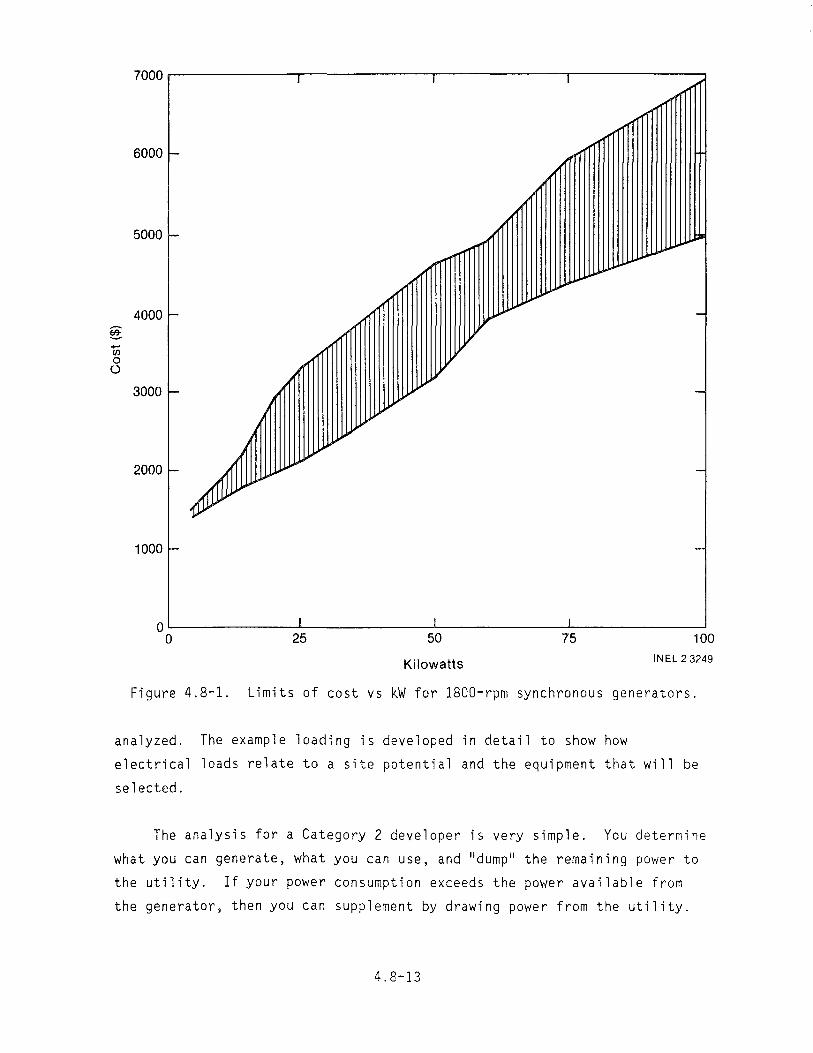
7000~-----------'-1-----------'1-------------'1-------------'
6000 I
5000 e
4000 I- ~ +-' CJ) 0 ()
3000 r-
-2000e-~
1000 f-
OL-___________L-I____________L-I__________~I------------~
o 25 50 75 100
Kilowatts INEL 2 3249
Figure 4.8-1. Limits of cost vs kW for 1800-rpm synchronous generators.
analyzed. The example loading is developed in detail to show how
electrical loads relate to a site potential and the equipment that will be
selected.
The analysis for a Category 2 developer is very simple. You determine
what you can generate, what you can use, and "dump" the remaining power to
the utility. If your power consumption exceeds the power available from
the generator, then you can supplement by drawing power from the utility.
4.8-13

900 rpm
1200 rpm
9000r---------r-------~------r-~---------,
8000r I
7000r
6000
5000
~ -III 0 0
4000
3000
2000
1000
O~------~--------~--------~------~ o 25 50 75 100
Kilowatts INEL 2 3248
Figure 4.8-2. Cost vs kW for induction generators.
4.8-14

The load analysis for a third situation is even simpler. This is
where a Category 2 developer desires to sell all of the power produced to a
utility. This system requires little load analysis. The generator will be
sized to produce maximum power on the basis of flow, head, and investment
capital.
4.8.8 Sizing the Electrical Distribution System
After you have selected a generator and the ratings of that generator,
you are ready to design the transmission and distribution system for the
electrical energy produced. This is the wiring system that distributes the
electrical energy from the' generator location to the point of use. It will
consist of wiring, overcurrent protective devices, such as circuit breakers
or fuses, panelboards, load control systems, and in the case of the
Category 2 developer, transformers and high-voltage protection devices.
Figure 4.8-3 is a one-line diagram showing the various components of a
typical power system for a Category 1 developer. The generator will have a
set of wires from its load terminals to the generator overcurrent device
(see Subsection 4.8.9).
Generator overcurrent protection 1.25 x full load amps of generator
Minimum r distance 1/
,...., ~--~-o o--+~--~----~-o o------------~~--_o 0---
Generator ground Feeder conductors
240 volt single phase F"'\Service discount _--00-
sized for house ....__AOF"'\o-service
Individualf"""\ r.... branch
___;..or....o-- circuits\p. f . ___.;..or....o-oint 0 service to residence
from generator (1.25 x full load amps)
One line diagram
INEL 2 3250
Figure 4.8-3. One-line diagram of typical power system for a Category 1 developer.
4.8"15

The main panel can be located at the house. The electrical wiring
from the generator overcurrent device to the house can be installed over
head or it can be directly buried in earth or pulled in buried conduit.
The length of this feeder wire has a bearing on the wire size of the wire
required for this feeder. The effect of the feeder length is known as the
voltage drop of the feeder.
The size of the residence1s electrical service equipment is set by the
NEe. The residence1s service entrance wiring and panels must be sized
according to its connected load and then derated as allowed by the NEe. There could be a circumstance where the house service wiring and service
disconnect may be considerably larger than the feeder that supplies the
house from the generator. A load control system will control this maximum
load, but the service will still require the minimum size dictated by the
NEe. All electrical overcurrent protective equipment and wire is sized on
the current carrying capacity of the equipment. The equipment and wire
also have a voltage rating that states that the equipment will safely
operate at a given voltage.
Wire ampacity is sized for a single-phase unit from the equation
I - 1000 x P (4.8-1)- E
where
I = amperes
p = power in kW
E = voltage
1000 = kW to watts conversion function.
4.8-16

Using the example of the 15.5-kW, 120/240-volt, single-phase generator
for the rural site, we find the minimum ampacity of the conductor to be
I = 1000 x 15.5 , or240
I = 64.6 amperes.
The NEC requires that the conductor be rated for 125% of its
continuous full-load current. Since the generator must operate fully
loaded to maintain frequency and speed requirements, the wiring and
overcurrent devices can be considered to carry continuous loads. Therefore:
I = 1.25 x I (4.8-2)m
where
= minimum wire ampacity
1.25 = 125%
I = amperes, from Equation (4.8-1)
Thus, for the example
1m = 1.25 x 64.6
I =80.7 amps minimum wire ampacity m
This ;s the minimum ampacity of the wire. You should use wire with a
higher ampacity than minimum for your installation. Table 3.10-16 in the
NEC Handbook can be used to select the proper size wire with insulation
that is heat and water resistant (Type THW).
CAUTION: All conductors must have mechanical protection such as
conduit or direct burial cables, or be suspended at least 18 feet above
ground.
4.8-17

Voltage drop is also a consideration if the load is located a long
distance from the generator location. Voltage drop can be calculated as
follows:
I x R x = (4.8-3)ED 1000
where
voltage dropED =
I = amperes
R = resistance of wire in ohms per 1000 feet (see NEe
Handbook, Table 8)
= length of wire in feet
Voltage drop should be limited to a maximum of 5% of the voltage. To
figure the percentage of voltage drop, take the calculated voltage drop
[ED from Equation (4.8-3)J and divide by the line voltage (E).
ED % drop =r- x 100 (4.8-4)
where
% drop = percentage of voltage drop
ED = calculated voltage drop in volts
E = line voltage (e.g. 120, 208, 240, 480)
If I (amperes) is constant and the length of the line is fixed, then
the only other variable is R (the resistance of the power line). The
resistance decreases as wire size increases. Voltage drop will not be
4.8-18
problem in most microhydropower installations, because the current is
limited to the current produced by a 100-kW generator. The distance to the
load or point of power consumption will be short, generally less than
500 feet.
4.8.9 Overcurrent Protection
The amperage rating of overcurrent protection devices can be selected
in the same fashion as the minimum ampacity for wire. From
Equation (4.8-2):
I = 1.25 x I m
The ampacity of overcurrent protective devices has to be selected from
standard ratings. The NEC will allow the use of the next higher rated
device. (For the example of 80.7 amps, a 90-amp breaker can be used.)
The overcurrent device for the generator should be located as close to
the terminals of the generator as practical. This device can be mounted
right on the generator and can be specified to be supplied with the
generator by the manufacturer.
4.8.10 Step-Up Transformer
When connecting to the utility, the Category 2 developer will need a
step-up transformer that will interface between the generator voltage and
the distribution voltage of the utility. This transformer will have to
have a kilovoltampere (kVA) rating that is equal to or greater than the kVA
rating of the generator. This transformer should have a low-voltage
overcurrent device located near the transformer and must have a
high-voltage fuse and lightning arrester located on the high-voltage side
of the transformer. Again, the high- and low-voltage overcurrent
protective devices should be rated at 125% of the full-load, high-side, and
low-side currents of the transformer.
4.8-19

CAUTION: The utility's high voltage is dangerous. The utility will
make the final connections.
The utility may require additional protective relays. These are
discussed in Subsection 4.8.13. The sizing of these devices is critical to
the operation of the system. That equipment can be determined
cooperatively by the developer, the utility, the electrician, and the
supplier when the equipment is needed.
4.8.11 Grounding
Grounding of the power system is very important. If you plan to
produce power at 120/240 volts, single-phase; 120/208 volts, three-phase,
four wire wye; or 277/480 volts, three-phase, four wire wye; then a very
definite ground reference point for the electrical system neutral needs to
be established.
If you wish to establish voltage at 240 volts, three-wire,
three-phase, delta; or 480 volts, three-wire, three-phase, delta; then an
additional ground needs to be established for equipment grounding. Delta
generation systems are not recommended for personnel safety and equipment
protection reasons.
The NEC requires that a buried metal water pipe with direct contact in
earth for a length of 10 feet or more be used as the main grounding
electrode. This ground point has to be supplemented with one or more
additional ground points. It would be desirable to plan at least 15 feet
of buried metal water pipe at the generator location. Other methods of
establishing a system ground are discussed in Article 250 of the NEC
Handbook.
It has been found to be good practice to weld all of the rebar in the
equipment pad as part of the ground system. This rebar should be at least
20 feet in total length and at least 1/2 inch (No.4) in size. If these
requirements are met, the rebar can be connected to the generator as the
ground system.
4.8-20
Additional ground points that have to be bonded to the metal water
pipe are the metal frame of a building, if available, and a ground ring
encircling the building consisting of at least 20 feet of bare copper wire,
not smaller than No.2 AWG.
Additional ground points to supplement the generator grounding
electrodes are other metal underground structures and pipes, rod and pipe
electrodes, and plate electrodes 2 feet square.
To summarize, the generator ground should consist of the following:
1. All grounds bonded or connected together at one point, preferably
in the overcurrent device enclosure.
2. At least 10 feet of buried water pipe, such as metal penstock,
waterline, etc.
3. A ground connection extending from the rebar of the equipment
pad. All the rebar in the pad should be welded together.
4. A No.2 AWG copper ground wire encircling the generator
building. This ground wire can be put in the ground when the
footings are dug.
5. A ground wire to the metal frame of the building if the building
is metal.
6. Additional buried structures or pipes, rods, etc.
Ground Systems 1 through 5 are required, if available at the generator
site. Ground System 6 can be used if available.
You should install the best ground system that you can implement to
maximize the safety of the system.
4.8-21

4.8.12 Governors and Load Control Systems
In order to maintain the generator at a constant 60 hertz (Hz)
frequency, it is necessary to maintain the generator shaft at a constant
rotational speed. In a stand-alone system, the rotational speed of the
microhydropower generator can vary as loads are added to or subtracted from
the electrical system. When Equation (A6-14) is rewritten to solve for
frequency (f), it can be seen that frequency varies directly with rpm since
the number of poles are fixed in any secific generator.
120 x r~m (A6-14)f = p
where
f = frequency in Hz
rpm = revolutions per minute
p = number of poles.
Therefore, it is desirable to either control the speed of a hydropower
generator by throttling the water to the turbine, or control the load of
the power system so that the load always remains constant. Speed control
is achieved with an electromechanical governor that controls the flow of
water entering the turbine. A load control system maintains a constant
load on a generator by using electric relays, or electronic switches, or a
combination of both to continuously correct the load to the required level.
4.8.12.1 Governors. There are many small plants that use governors
for speed control. The governor usually consists of a vertical shaft that
has counter opposed flyweights suspended from the top of the vertical
shaft. As the speed of the shaft increases or decreases, the flyweights
move up or down the shaft, respectively. This movement is amplified,
4.8-22

usually hydraulically, so that small variations in speed can be sensed and
a proper control signal transmitted to the valves or deflectors that
control the water pressure.
The industry standard governor is a Woodward Type UG, hydraulic
turbine control. The same governor that is used on large hydroelectric
plants is the one that is used on microhydropower plants. This governor is
capable of an output of 8 foot pounds of torque. This output is adequate
to power some methods of speed control such as operation of deflectors to
deflect the water emitted from the nozzles of a small Pelton wheel. If a
means of conserving water is desired for a plant operating from reservoir
storage, the governor signal must be amplified again to be able to close a
valve to adjust flow. The second stage of amplification is usually
accomplished by a larger hydraulic pump that actuates a ram to move the
valve actuator. This actuator must respond quickly enough to maintain
adequate frequency control, but the flow of water cannot be changed so
rapidly that damage to the penstock occurs. Governors are able to provide
speed control for a microhydropower installation in the range of 85% of
full load speed to 110% full load speed.
4.8.12.2 Load Controllers. Many small hydro plants are using
electrical and electronic control schemes. Frequency can be measured
electronically and compared against a set point. If the frequency measured
is low, i.e., the system is overloaded, then a low-priority load can be
deenergized. This method is referred to as Electrical Relaying. Loads can
be added or dropped in discrete units. Obviously, the type of load that
can be started and stopped often must be one that will not create a hazard,
an inconvenience, or a premature equipment failure by being automatically
switched in and out. The best loads for intermittent switching are
electric heating loads. Motors will overheat and can fail if started and
stopped too often.
The development of solid-state electronics has provided many devices
that switch much faster and are as reliable as the older electromechanical
relays. Some of the solid-state switching devices are used only for
electronic logic and signalling, while others are able to handle power
4.8-23
loads directly. The silicon controlled rectifier (SCR) or triac is
commonly used to switch power loads.
Electronic switches or triacs are capable of controlling the
electrical waveform to produce a frequency of 60 hertz but with a
diminished amount of power. A load can, therefore, be varied continuously
over the range from zero voltage to full load voltage.
An electronic load control system can sense changes in the generator
output and can adjust the load by switching electric relays and by
controlling electronic switches that can continuously vary their connected
load to match the generator output.
Consider the load system that was plotted in the run-of-the-stream
example problem (Appendix B).
The system has loadings that must be capable of continual operation
and cannot be controlled, such as:
Refrigerator• Freezer• Well pump• Kitchen equipment • Kitchen range• Lighting• TV and stereo• Shop equipment.•
The loads that can be controlled by the load control system are:
• Water heaters
• Electric dryers
• Electric heat during the winter
• Electric heat loads in other areas, which can be added to keep
the generator fully loaded.
4.8-24

With the operation scenario given in the example in Appendix B, the
power system will have a base load that varies between 2.2 and 13.6 kW.
This leaves the remainder of the generator output for other controlled
loads. Electrical water heaters can be installed and set up to be used to
control load, operating whenever the generator loading allows.
In addition, the owner of this system needs a heat load operated
through an electronic switch that will allow the load to be continuously
varied as the other loads vary. For example, 6 kW of baseboard heater
could be installed in the greenhouse to provide this load. The other
loads, such as the water heaters or house baseboard heaters, can be
switched on a priority basis by relays as the loading of the generator
allows.
EXAMPLE: At 4 p.m. one day, the generator has a base load of 7.4 kW
that is a combination of kitchen loads, shop loads, lighting loads,
and the well pump. Since the generator is operating at full capacity,
this leaves 6.6 kW of loads to be controlled. A frequency monitor
notes the need for additional loads and sends a signal to the load
control panel to start controlling the loads.
The first priority load is switched on--6 kW of greenhouse heat.
There are still 0.6 kW of generated power that need to be consumed.
The second priority load, a water heater, comes on. This load is
4.5 kW. Therefore, the first priority load is reduced by use of the
triac switch to 2.1 kW. Thus, there are 2.1 kW of load in the
greenhouse heaters that are now being controlled by the triac. As the
base load increases, this varied load will be reduced to zero. Then
the loads on priority control will be switched off.
By controlling the loads in this fashion, the system controls the load
on the generator and keeps the frequency constant. The load control system
is suited for stand-alone power system because it allows the generation
system to operate at peak efficiency.
4.8-25

4.8.13 Utility Tie-Ins
There are several reasons for connecting to a utility grid.
• Generation of revenue. If the generation of revenue is a
primary concern, the developer will want to tie into a utility to
maximize the return on investment.
• Load sink. For Category 1 developers able to consume the
majority of the power generated by the site, the utility may
provide a load sink by taking the excess energy and keeping the
system fully loaded.
Power Backup. The utility can act as a backup power source for
the Category 1 developer whose system is down for repairs, or
when the water source is too low for power production.
• Reduction in equipment costs. Connection to an outside system
alleviates the need for expensive speed-regulating equipment.
Utilities have many different requirements for connection to their
power lines. These can range from as little as a lockable disconnect
switch at the point of tie-in to the utility system, to a total control
system that involves power metering, telemetering, and protective relaying.
The utility will require that protective equipment be installed for
the following reasons:
• Safety. There are times when the power line will be down for
maintenance or repairs, or due to accidents, and the generator
will have to be taken off the power line. This will require both
automatic and manual disconnects.
Protection of the generation equipment. There are instances
where the generator should be taken off the power line to
minimize the potential for damage.
4.8-26

• Utility safety. The utility will also require protection for
their system and equipment.
The protection equipment that must be installed on a microhydropower
site for utility intertie depends on the requirements of the utility. You
will have to provide overcurrent and short-circuit protection for the
output of the generator. Some utilities may require little more than a
lockable disconnect switch on the line side of the generator overcurrent
protective equipment. Another protective system may be a high-voltage oil
switch controlled by an undervoltage relay. This equipment would be owned
by the developer. There are many other inexpensive potential protective
schemes.
The most sophisticated and expensive protective system currently being
proposed by utilities requires over- and undercurrent protection, over- and
undervoltage protection, differential phase protection, and reverse power
protection. If the generator is a synchronous machine, the utility will
also require a synchronizing device to connect the generator to the system.
The protective equipment listed above will probably have to be
industrial grade. This equipment and the associated voltmeters, ammeters,
kilowatt meters, switches, and protective equipment become expensive when
mounted in a cabinet and installed at the site.
Some utilities may require notification each time the generator is
connected online. Notification can be made either by a telephone call or
by telemetering equipment installed to monitor the generator1s activity.
This notification is for the safety of personnel working on the line.
CAUTION: The protection and disconnect system may appear expensive to
the developer. However, the intent of this protection is to protect life
and property. Work wi th the uti 1i ty fo·r thi s goa 1.
The utility will require you to install, maintain, test, and calibrate
metering equipment to measure the flow of power into the utility1s grid.
This metering will be by a kWh meter that measures power "out ll from the
4.8-27
generator. The utility may also require a power lIin ll meter to measure both
demand and kWh used by the m;crohydropower system.
The utility may also require that you install metering to measure
reactive power, or kilovar hours. This would normally be when you are
using a large induction motor as a generator.
You will also have other equipment on the system that will have to
intertie with a utility. This will include step-up transformers,
protective equipment, and a high-voltage power line. Most utilities will
quote you a price for installing this equipment; others will insist on
installing the equipment so that it is installed according to their
standard practices.
You will have to maintain the high-voltage line and step-up
transformer. A utility may do this for you but they will charge a
maintenance fee.
CAUTION: Make sure that the people working on the high-voltage line
are qualified and capable of performing this work.
You may elect to have the power company install and maintain the
protective equipment, step up transformer, and power line. The power
company would be paid for al.l of their installation work at the time the
equipment is installed. A separate maintenance contract would then be
written between you and the utility specifying that you pay the utility a
monthly percentage of the construction cost for maintenance.
Another arrangement could be for you to contract with private firms
for all equipment installation and then set up a maintenance agreement with
the utility specifying a flat rate for maintenance and repairs.
There are many other requirements that a power utility may impose upon
the microhydropower developer. These requirements may cost money and would
have to be included in all financial analyses of the system.
4.8-28

Following are additional requirements that you need to consider
carefully for their legal implications.
• Power factor correction. Power factor corrective capacitors may
be required to correct the line power factor to 85% or even 95%
when an induction motor is used as the generator. These
capacitors could be mounted at the generator site or could be
furnished to the utility to be mounted on another segment of the
power line remote from the generator location.
CAUTION: When capacitors are used with induction motors, the
motor may continue to generate power even when the utility power
is interrupted. This could be a potential hazard to utility
personnel and should be discussed with them if they require the
use of a capacitor.
Liability insurance. This insurance could be required to
indemnify the utility or developer from loss, damage, expense,
and liability to persons who could be injured by the developer's
or utility's construction, ownership, operation, or maintenance
or by failure of any owner to maintain the system. Insurance
limits of $1,000,000 or more could be required.
Easements. The developer will require easements and
right-of-ways to the utility for any interconnection equipment
and will therefore need a surveyor to write up the easement.
Shutdown impacts. The contract may also address what happens
when the utility or developer has problems that cause the loss of
power generation capabilities by the developer or the utility.
This item needs to be addressed to minimize the impact of the
shutdown.
The microhydropower developer should remember that the utility is in
business to distribute and sell power. The utility desires to generate its
own power or to buy power in bulk. The role of the microhydropower
4.8-29

developer as power producer is somewhat minimal to a utility. Therefore,
the microhydropower developer will need to maintain a good rapport with the
utility and should be willing to work with their requirements.
4.8-30

4.9 Drive Systems and Speed Increasers
The drive system is used to mechanically connect the turbine shaft to
the generator shaft. This connection may take one of several forms
depending on turbine speed and preference of the designer. Where the
turbine speed matches that of the generator, the shafts of each are
directly connected using a coupling. When the turbine rotates either
slower or faster than the generator, a speed increaser or reducer must be
installed in the system. This may take the form of a gear drive, belt
drive, or chain drive.
Most generators will be selected in the 900 to 1800 rpm range for
microhydropower applications. Once the turbine has been selected and its
rotational speed determined, the ratio of generator speed to turbine speed
can be calculated.
GrpmR =T (4.9-1)
rpm
where
R = Speed Ratio
;:: Generator speed in rpm
= Turbine speed in rpm.
EXAMPLE: Assume that the turbine operates at 600 rpm and an 1800-rpm
generator is being used; find th~ ratio.
R = 1800 600
R = 3
4.9-1

Therefore, the drive system selected must be capable of converting
every revolution of the turbine into three revolutions of the generator.
The power that a drive must transmit is an important consideration
when selecting and designing a drive system. In Subsection 2.5, the basic
power equ?tion was given. An efficiency of 60% was recommended for use in
calculating your system's power. This power should not be used to size
your drive system, since some of the losses included in the 60% will not be
present between the turbine and the drive. The most accurate method of
determining the power developed by the turbine is to use the basic power
equation but to substitute the turbine efficiency provided by the
manufacturer for "e" and the site's net effective head (see Subsection 2.2)
for "hl!. If neither of these values are known, an assumed efficiency of
100% and the pool-to-pool head can be used. This will be conservative and
oversize your drive but can be used in preliminary calculations.
4.9.1 Direct Connection Drives
When the turbine speed matches the generator speed, direct connection
offers advantages over speed increasing or reducing devices. Direct
connection avoids the efficiency losses associated with speed changing
devices, maintenance is minimal, and the system is more compact. The major
disadvantage of a direct drive is the possible damage that could occur
should either the generator or turbine suddenly "lock up" from a lightning
strike or debris entering the turbine. The damage to the still rotating
component and shafts could be extensive in this case. Even with this
disadvantage, however, direct drive is a highly desirable feature.
The connection of the generator shaft to the turbine shaft can be done
with either rigid or flexible couplings. Rigid couplings provide a fixed
union between the shafts, requiring that the shafts have good initial
alignment and stable support bearings. Misalignment can cause worn or
failed bearings, fatigued shafts, broken coupling bolts, or worn bores in
the coupling flanges. The three principal types of rigid couplings are
compression, ribbed, and flange-face. These are illustrated in Figure 4.9-1.
4.9-2

Compression couplings attach to the shafts by the compressive force
generated when tapered sleeves are wedged inward as the two halves of the
coupling are drawn together by tightening bolts. This coupling is suitable
for light to moderate torque loads. A ribbed coupling employs a long key
set in keyways in both shafts and the coupling housing to lock the shafts
together. A flange-face coupling uses keys to lock the individual flanges
to each shaft and the flanges are then bolted together. Both of the latter
two couplings are capable of sustaining high torque loads. These couplings
are not particulatily suitable for axial loads (loads along the shaft
axis). Such loads result from hydraulic thrust of the turbine or from the
weight of the rotating components on vertical turbines. If such loads
exist, a flange that is an.integral part of the shaft should be used.
In cases where misalignment between the shafts can be expected, a
flexible coupling should be employed. These couplings are common and are
referred to as chain, slider, gear, and flexible member couplings. These
couplings may be particularily unsuitable for axial loads. When using
these couplings, contact the coupling manufacturer for specific data on
load (torque and thrust), deflection, and speed capabilities.
4.9.2 Speed Changing Drives
For the majority of microhydropower sites, some sort of speed
increaser drive will be required because of insufficient head or flow to
operate the turbine at generator speed. These drives will increase the
cost of the installation but are necessary in order to provid~ synchronous
speed for ac generator operation. It is possible that the turbine could
rotate faster than the generator in special cases. A speed reducer type of
drive would be needed in this case, and the same information is applicable
as with speed increasers.
4.9.2.1 Chain Drives. Chain drives have many applications and have
the advantage of high efficiency, no slippage, and relatively high load
capacity and life. Like couplings, they lock the generator and turbine
shafts together, which can cause damage if one component stops suddenly, as
4.9-3

Compression Tapered coupling sleeve
Ribbed
Flange-face coupling
INEL 2 2347
Figure 4.9-1. Types of rigid coupling.
previously discussed. Manufacturers catalogs are the best source of
information on procedures for selecting and specifying chain drives. Input
information required includes: transmitted power, speeds of driving and
driven shafts, space limitations, center distances, and operating
conditions. If you determine that a chain drive is the type of system you
4.9-4

wish to install, you should contact a manufacturer for further
information. Normally, belts are preferred to chains for microhydropower
applications because they are less costly to install and maintenance is
minimal.
4.9.2.2 Belt Drives. Belt drives provide the lowest cost means of
transmitting power from one shaft to another. They operate smoothly and
quietly and can absorb appreciable shock. Slippage of the belt and its
sheave can occur if the shaft of either the generator or turbine locks up,
providing an added measure of protection to the equipment. The basic power
transmission belt is the V-belt. It provides the best combination of
tractive force, operating speed, and service life. Flat belts were the
first belt used for industrial power transmission and still find
applications today. To prevent slippage of flat belts during operation,
however, the belt must operate under high tension. Such high tensile loads
require heavier shafts and bearings, as well as a heavier mounting
framework for the drive. Synchronous belts have evenly spaced teeth on the
bottom surface that mesh with grooves on the pulley to produce a positive,
no-slip driving effect similar to a chain drive. While these belts can be
used for microhydropower applications, there does not appear to be any
advantage over using a V-belt, and they are more expensive. V-belts are
considered the best selection for belt drive arrangements.
To facilitate interchangeability and insure uniformity, V-belt
manufacturers have developed industry standards for various types of V-belt
drives. Three major areas of application--industrial, agricultural, and
automotive--are covered by the standards. Only the industrial type of
belts are of concern for microhydropower use.
Industrial V-belts are made in standard cross-sections and are
referred to as conventional, narrow, and light duty. Conventional belts
are available in A, B, C, D, and E cross-sections; narrow belts are made in
3V, 5V, and 8V cross-sections; and light duty belts come in 2L, 3L, 4L, and
5L cross-sections. Belts are designated by a symbol for the cross-section
accompanied by the length designation. The length designation is in inches
except for narrow belts where it is in tenths of an inch. For conventional
4.9-5

belts, a B90 belt has a B cross-section and is 90 inches long. For a
narrow belt, 5V1400 indicates a 5V cross-section and a 140-;nch length.
Belts carrying the same designation and power rating are interchangeable.
The selection of belts should be done with the help of a manufacturer
or his catalog. There are several terms that the developer must be
familiar with in order to properly design a belt drive. The wheel on which
the belt operates is referred to as the sheave or pUlley. As the belt
bends around the sheave, the outer belt surface is stretched while the
inner surface is compressed. In the middle of the belt is a neutral axis
that does not change circumferential length. This line that does not
change length is called the pitch line, and it forms a pitch circle with a
pitch diameter on the sheave. The sheaves are selected and sized by their
pitch diameter in the catalogs. The distance between sheaves is called the
center distance. Figure 4.9-2 illustrates belt drive terms.
The sheave diameter and belt cross-section are selected in a
preliminary manner from charts and tables in a manufacturers catalog.
Selection is always based on the smaller diameter sheave, which revolves at
the highest rate. The chart shown in Figure 4.9-3 is for the preliminary
selection of conventional cross-section belts. Similar charts exist for
narrow and light-duty belts.
Once the type of belt has been selected, the smaller sheave diameter
can be selected from a table. Table 4.9-1 is typical of the tables found
in catalogs. It gives minimum recommended pitch diameter for the smallest
sheave. To use a smaller sheave than recommended would fatigue the belt,
reducing its operating life. The pitch diameter of the larger sheave is
found by multiplying the speed ratio and smaller diameter sheave together.
This large sheave diameter is compared to standard sheaves available in
catalogs, and the sheave with the nearest diameter is selected.
4.9-6

.,,;-- ...... , / '\
" \" \, \ I
_ ___---;_...s-hteave7Center _ distance
Sheave
INEL 2 2278
Figure 4.9-2. Belt drive terms illustrated.
TABLE 4.9-1. SHEAVE DIMENSIONS
Belt Section
A B C D E
Belt Size ( in. )
1/2 x 11/32 21/32 x 7/16
7/8 x 17/32 1-1/4 x 3/4 1-1/2 x 1
Minimum Recommended
Pitch Diameter ( in. )
3.0 5.4 9.0
13.0 21.6
4.9-7

4000
3000
2000
'[ 1000 .::.. "C <D <D 0. 800 m <D >as <D
L:. 600.f a; E
CI) 500
200
A Small sheave = 2.6 to 5 in.
-~
B 4.6 to 7.5 in.
C1800 rpm 7 to 12 in.----""-------
4 6 10 20 40 60 100 Design power (hp)
Refer to manufacturer
D 12 to 20 in.
E 18 to 28 in.
200 400 600 1000
INEl22280
Figure 4.9-3. Conventional belt selection chart.
4.9-8

You can now calculate the power that the belts must transmit. The
power of the turbine is used as the starting point. This power rating must
be modified to account for starting loads, peak loads, intermittent service
conditions, and any other operating factors that may affect the rating of
the drive. These various conditions are incorporated in a service factor.
The turbine power rating is multiplied by this service factor to give the
design power of the belt drive. For hydroelectric turbines, a service
factor of 1.4 or 1.5 should be adequate. Therefore, if your hydroelectric
turbine is calculated to produce 10 kW and a belt system is to be selected
as the drive, the belts should be designed for 14 to 15 kW.
Calculate an approximate center distance unless the distance is
already fixed by the system design. A rule of thumb ;s that the center
distance should be 1 to 1-1/2 times the larger sheave diameter. Centers
should not exceed 2-1/2 to 3 times the sum of both sheave diameters. Once
the approximate center distance is calculated, you can calculate the
initial belt length with the following equation:
2 L = 2C + 1,57 (0 + d) + (04~ d) (4.9-2)
where
C = center distance in inches
o = pitch diameter of the large sheave in inches
d = pitch diameter of the small sheave in inches
L = pitch length of the belt in inches.
Compare the belt length to the manufacturer's standard belt lengths,
and select a belt closest to the calculated belt length. Then recalculate
the true center distance using the following equations:
4.9-9

K= L - 1.57 (D + d) (4.9-3)2
c = K _ (D - d)2 (4.9-4)8K
where
c = center distance in inches
L = pitch length of the belt in inches
D = pitch diameter of the large sheave, in inches
d = pitch diameter of the small sheave, in inches
K = a factor.
The remaining calculation is called the arc-length correction factor.
Horsepower ratings given in catalogs are for belts having a l80-degree arc
of contact. For drives other than these, a correction factor must be
applied. This factor can be found in catalog tables once you have
calculated the arc of contact. Use the following equation to calculate the
arc of contact:
(0 - d2 x 57 a = (4.9-5)C
where
= arc of contact in degrees
0 = pitch diameter of the large sheave in inches
d = pitch diameter of the small sheave in inches
C = center distance in inches.
4.9-10
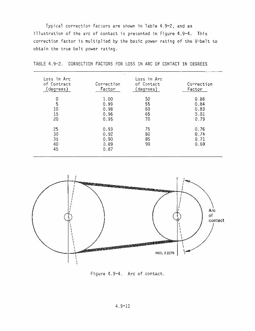
Typical correction factors are shown in Table 4.9-2, and an
illustration of the arc of contact is presented in Figure 4.9-4. This
correction factor is multiplied by the basic power rating of the V-belt to
obtain the true belt power rating.
TABLE 4.9-2. CORRECTION FACTORS FOR LOSS IN ARC OF CONTACT IN DEGREES
Loss in Arc of Contract (degrees)
0 5
10 15 20
25 30 35 40 45
Correction Factor
1. 00 0.99 0.98 0.96 0.95
0.93 0.92 0.90 0.89 0.87
Loss in Arc of Contact (degrees)
50 55 60 65 70
75 80 85 90
Correction Factor
0.86 0.84 0.83 0.81 0.79
0.76 0.74 0.71 0.69
J I I I I I I I I Arc
of I
1\ contact,,
\ \ \ \ \ \ \ \ \
INEL 2 2279 I,, \
Figure 4.9-4. Arc of contact.
4.9-11

Other correction factors are also used by manufacturers and will be
found in their catalogs. Corrections are used for long belt lengths and for
high speed ratios. Once you have determined the true belt power rating,
find the number of belts needed by dividing the calculated power rating of
the drive system by the power rating of the belts:
(4.9-6)
where
B = number of belts
= power rating of drive system (turbine power x service
factor)
= true belt power rating.
EXAMPLE: Assume that the turbine operates at 600 rpm and the
generator at 1800 rpm. The turbine power has been calculated at 10 kW
or 13.4 horsepower (10 kW x 1.34 hp/kW). Select the belts using the
following steps:
Step 1. Select Belt Type
From Figure 4.9-3 at 13.4 hp and 1800 rpm, the belt type
is "B".
Step 2. Power Rating of the Drive System
1.5 is the selected service factor. Therefore,
13.4 hp x 1.5 = 20.1 hp
4.9-12
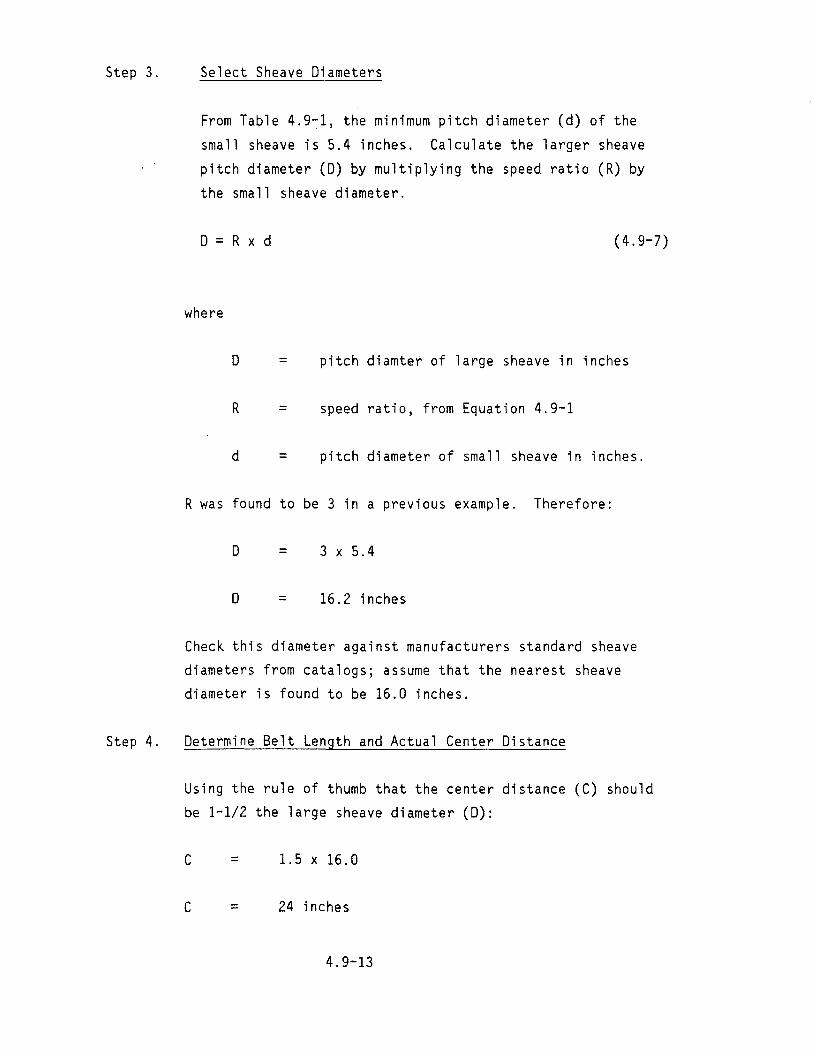
Step 3. Select Sheave Diameters
From Table 4.9-1, the minimum pitch diameter (d) of the
small sheave is 5.4 inches. Calculate the larger sheave
pitch diameter (D) by multiplying the speed ratio (R) by
the small sheave diameter.
o = R x d (4.9-7)
where
o = pitch diamter of large sheave in inches
R = speed ratio, from Equation 4.9-1
d = pitch diameter of small sheave in inches.
R was found to be 3 in a previous example. Therefore:
o = 3 x 5.4
o = 16.2 inches
Check this diameter against manufacturers standard sheave
diameters from catalogs; assume that the nearest sheave
diameter is found to be 16.0 inches.
Step 4. Determine Belt Length and Actual Center Distance
Using the rule of thumb that the center distance (C) should
be 1-1/2 the large sheave diameter (D):
C = 1.5 x 16.0
C = 24 inches
4.9-13

The belt length is calculated using Equation 4.9-2:
2 L = (2 x 24.0) + [1.57 x (16.0 + 5 4)J + (16.0 - 5.4) . 4 x (24.0)
L = 48 + 33.6 + 1.17
L = 82.77 inches
Checking a manufacturer1s catalog reveals that a B81 belt
has a pitch length of 82.8 inches. This is so close to the
calculated length that the center distance will not change
significantly. It is recalculated here as an example using
Equations 4.9-3 and 4.9-4:
K = 82.8 - [1.57 x (16 + 5.4)J = 24 62 .
K= 24.6
2C = 24 6 _ (16 - 5.4)
. 8 x (24.6)
C = 24.03
Step 5. Find the Horsepower Rating per Belt
The horsepower rating per belt is found in each
manufacturers catalog for his specific belts. Assume that
the manufacturers catalog allows 6.3 hp per belt after
considering correction factors for a speed ratio of 3 and a
long belt. Find the arc length correction factor, using
Equation 4.9-5:
(16 - 5.4) x 57 a = 24
4.9-14

a = 25.18 degrees
From Table 4.9-2, the factor is 0.93 for 25 degrees
hp = 6.3 x 0.93
hp = 5.86 per belt
Step 6. Determine Number of Belts
From Equation 4.9-6:
20.1 hp (power rating from Step 2) = 3.43 belts5.86 hp (per belt hp from Step 5)
Use 4 belts.
The drive selected then has the following specifications:
4 belts, Size B81
Turbine sheave--4 grooves, 16-inch pitch diameter
Generator sheave--4 grooves, 5.4-inch pitch diameter
It is important to select your belt drive system in accordance with
recommended practices. Belt drives optimized for compactness using the
latest technology usually have the longest service life. Both overbelting
and underbelting produce sizable energy losses. For example, the loss in
energy approximately doubles from 3% to 6% when a belt drive is operated at
only one-half the rated load capacity. In general, the energy loss due to
factors such as belt flexure remain constant even though the belt operating
load is decreased by half the rated capacity. Energy losses increase when
belt loads exceed their capacity due to belt creep and distortion. This
occurs when the belts are underdesigned.
4.9-15

Poor belt maintenance can be another cause of significant energy
losses. Low belt tension can cause losses of as much as 10%, and
misalignment, worn sheaves, and debris in the grooves all contribute to
efficiency loss and reduced belt life. Belt tensioning is an important
consideration, and the manufacturer's catalog should be reviewed or the
representative contacted to obtain data on correct tensioning of belts.
Belt drives should always be designed with center distance adjustment since
belts will stretch during use and require periodic adjustments.
4.9.2.3 Gear Drives. Gear drives provide the strongest and longest
service of the mechanical drive trains considered when speed increasing or
decreasing is required. They are also the most expensive drive systems.
If you feel that a gear drive is needed to couple the turbine and
generator, you should contact a manufacturer of such drives to assure
proper installation.
The most common gears used for the transmission of power between
parallel shafts are spur gears, helical gears, and herring bone gears.
Spur gear teeth are straight and parallel to the shaft axis. They have no
end thrust loads, and are economical to manufacture and easy to maintain.
Helical gears have teeth that form a helix. They have greater load
carrying capacity, and operate more smoothly and quietly than spur gears of
equivalent size. Helical gears ~re more expensive to manufacture and,
because of their design, they produce end-thrust that in turn requires
end-thrust bearings. Herring bone gears are double-helical gears that
eliminate the end thrust loads of single helical gears. These gears are
primarily used for the transmission of heavier loads, which would not be
present in microhydropower units. Their expense is probably not warranted
for small microhydropower installations.
If the turbine and generator must be mounted at right angles to one
another, several gear combinations can be used. The simplest and most
inexpensive are bevel gears, which have straight teeth and would perform
satisfactorily for microhydropower installations. More expensive gears,
which are quieter and can sustain higher loads, are spiral bevel gears and
4.9-16

crossed helical gears. Gear drives are also available for situations where
shafts are not parallel or perpendicular but are skewed at an angle between
zero and 90 degrees.
The design of gear drives is a complicated procedure and best left to
the manufacturers of those drives. The calculations for gear tooth,
bearing, and shaft loadings, as well as the selection of seals and
lubrication are major tasks beyond the scope of this book. When discussing
a gear drive with the manufacturer, be sure to have available the power to
be transmitted, speed ratio, space limitations if any, the arrangement of
the turbine and generator, and any thrust loads that the turbine may
introduce into the drive.
4.9-17

5. DESIGN PACKAGE, CONSTRUCTION, AND INSTALLATION
In this section you will assemble the design package (including the
final cost estimate and a construction schedule), order equipment and mate
rial, and construct and assemble the system.
5.1 Design Package
At this point in the project, you should have a clear idea of how the
project will look and what it will do. Events 1 through 22 in the event
schedule given in Section 1 should be completed or in progress. All design
information should now be put into a single design package so that you can
readily refer to any design aspect of the job or track costs and progress
during construction. This design package will also help identify problems
during initial system startup and during later operation and maintenance of
the project. As you obtain equipment manuals and other information during
construction, add these to the design package.
The design package should consist of final construction drawings, spec
ifications or data sheets for major components, material takeoff sheets, bid
packages, cost estimate, and final schedule. Depending on your particular
site, you may not need some of these items in the design package. The pur
pose of the design package is to ensure the following:
All site considerations and constraints have been identified
I All equipment has been identified and selected
The size and operating specifications for the equipment and mate
rial are compatible
All construction material has been identified
All outside labor has been identified
I All known problem areas have been identified and solved
5-1
• The budget and schedule are reasonable and realistic.
5.1.1 Final Drawings
Collect and review all sketches drawn in Section 4. Correct any defi
ciencies in the design. Provide clear sketches to identify the work to be
done by a contractor or someone else. The drawings need not be profession
ally done, but they should be drawn to scale and show enough detail so that
contractors and inspection officials will clearly understand the project.
Copies of the drawings will be needed, and therefore the drawing size and
material should be compatible with the copying method. Drawings on letter
size graph paper can be photocopied, but larger drawings can only be repro
duced using a blueprint or similar process.
The recommended drawings include one sketch showing the entire system
and several smaller ones showing details of specific components. An eleva
tion cross section should be drawn that includes the elevation of the
intake, powerhouse, and tailrace; it should also include the gradient or
slope of the penstock. The final drawings should contain enough detail so
that an accurate materials list can be generated. Forgotten or insufficient
materials can cause serious delays during construction.
The agencies responsible for issuing the permits you must obtain will
be more receptive when you present complete plans and working drawings.
Furthermore, you will save time during the permit process by having good
drawings so that specific questions can be answered quickly.
5.1.2 Data Sheets, Specifications, and Bid Packages
The major data sheets you should have at this point are the Turbine
Generator Information Request in Subsection 4.2 and the Design Specification
in Subsection 4.3. If data have changed since the basic concept was pre
sented to the manufacturers, resubmit the new data--for example, new site
characteristics--to ensure that the turbine-generator will function properly
at your site. The data sheet submitted by the turbine manufacturer should
also be in the design package.
5-2

For large turbines and other large equipment, you may want to write a
formal bid specification. This can be a performance specificaton or a pro
curement specification. The former specifies performance characteristics;
the latter specifies equipment. In most microhydropower applications, for
mal specifications will not be necessary, but you should still prepare data
sheets that describe the performance requirements of major equipment to be
purchased. This allows you and the manufacturer to agree on equipment
performance and costs.
For items such as pipe, valves, wiring, and concrete, you can call or
visit several suppliers to obtain quotes for the items without bothering to
use data sheets. This is an acceptable method, but a written quote with a
description of any ordered items prevents unwelcome surprises when the items
are delivered. Although this paperwork may seem unnecessary, it takes
little time and provides a record of the purchase agreement.
Poor timing in the ordering and delivery of material and equipment can
delay construction. For example, it may take from 6 months to a year to
obtain a turbine-generator, and therefore delivery times should be known and
ordering complete before constructin is begin. Always request that sup
pliers state delivery times when discussing material procurement.
5.1.3 Material Takeoff Sheets
To estimate cost and order material accurately, a material list must
be prepared. Carefully review each drawing and sketch to determine exactly
what material must be procured. (This further points to the need for accu
rate drawings and sketches.) List each item to be procured on a II ma terial
takeoff sheet." This sheet should contain a description of the item, the
quantity, and the name of the supplier, if known. An inaccurate list can
waste time and money: the cost and time to deliver a couple of forgotten
lengths of pipe or an additional 4 cubic yards of concrete to a project in
a remote area can be substantial. You should therefore recheck the material
takeoff list to ensure that all needed items are ordered. Order spares if
an accurate count cannot be made, or if some items could be lost or damaged.
Most suppliers will allow you to return undamaged extras that are not
needed.
5-3

While estimating the material needed for the project, include construc
tion material such as concrete forms, scaffolding, and earth moving equip
ment; include these on your material takeoff sheets.
5.1.4 Detailed Cost Estimate
A detailed cost estimate includes the material cost, the estimated
labor cost to install or construct an item, and any equipment rental
required. The material takeoff sheets should be used as starting points for
preparation of the cost estimate.
The three most common materials on the sheets will be concrete, wood
for concrete forms and for the powerhouse, and pipe for the penstock. The
length of penstock should be known by this time. If concrete is purchased
commercially, keep in mind that it is sold by the cubic yard and that
1 cubic yard equals 27 cubic feet. From the working drawings, determine the
volume of concrete in cubic yards for the entire project. For example, a
forebay wall that is 5 feet tall, 8 feet long, and 6 inches thick would have
a total volume of 16 cubic feet (4 x 8 x 0.5 = 16), or about 0.60 cubic
yards (16 ~ 27 = 0.60).
Figure 5-1 is a suggested form to help determine the project cost. For
a given item, the form lists the description, material quantity and units,
material cost per unit, unit labor hours to install material, total labor
hours, labor rate, labor cost, material cost, and total cost. All material,
labor, rentals, and equipment should be included in the cost estimate.
Copies of the form can be found in Appendix I.
For the total estimated cost, sum the above estimated costs, add 10%
for administration (permits, etc.), and then 15% of that sum for
contingency.
EXAMPLE: Assume that the summed estimated cost is $10,630; find the
total estimated cost.
For administration cost, $10,630 x 0.10 (10%) = $1,063.
The sum is then $10,630 + $1,063 = $11,693.
5-4

Microhydropower Date
Detailed Cost Estimate Page of
Prep. By
Mat'I UnitMaterial Total Other TotalLabor MaterialLaborr Description LaborQuantity Unit Labor CostCost Cost CostRate& Units Cost Hours Hours
(J1
I (J1
INEL22412
Figure 5-1. Cost estimate form for Microhydropower project.
For contingency, $11,693 x 0.15 (15%) = $1,754.
Thus, the total estimated cost is $11,693 + $1,754 = $13,447.
Now, make the final go/no-go decision. Like the previous decisions,
this one should be based on economics. Category 1 developers can compare
the total project cost to the benefit gained from the project. Category 2
developers should do a more detailed analysis using the procedure outlined
in Subsection 4.3.1. If the decision is to proceed, refer back to
Section 1.5 to make sure that Events 27 through 32 are completed before
starting construction.
5.1.5 Construction Schedule
Prepare a construction schedule to determine when work on the project
must be done, or when it can be done. In developing the schedule, be sure
to consider the following:
• Weather--In cold climates, winter can present a serious obstacle.
Snow and cold can make the job unpleasant and may affect the
quality of the work. Concrete in particular is difficult to work
with in freezing temperatures, and concrete work should be sched
uled for the best weather possible.
• Streamflow--Work on streams is easier if done in the dry season,
which, for most of North America, is in late summer and early
fall. Check the stream flow data to determine the dry time.
• Use of Machinery--If you rent small construction equipment such
as a backhoe or grader, identify and schedule the tasks for which
it will be used before the unit arrives so that you can get
maximum output for least cost.
• Availability of Contractors--As the schedule is developed, make
sure that the contractors will be available at the time allocated
for the task. Make sure that the contractors understand clearly
what is expected of them. Use the working drawings to help in
this process.
5-6

• Availability of Material--To meet a construction schedule, it is
important that the material be on the site when needed. Although
more common items can usually be obtained as stock items from
local building material suppliers, specialty items such as pen
stocks, valves, and turbine-generator sets must be ordered;
delivery times can be critical.
Several people can work on different parts of the system at the same
time. For example, one may be digging the penstock trench while another is
stringing the transmission line. If only one person is building the system,
construction time will obviously be correspondingly longer. Keep in mind
that projects of this kind will almost always take longer than anticipated,
especially the first time. When scheduling work, take care that unexpected
delays don't push critical parts of the project into the winter months.
Concrete work should be done when above-freezing temperatures are assured
for one week following the pour. Otherwise, the fresh concrete will have
to be protected.
A construction schedule is a working document. Even the effort to
generate one will be helpful. Most of the needed information is developed
for the drawings and cost estimates. To develop the schedule, you will
need a list of tasks, their sequence and duration, and who will do them (if
more than one person is on the project). A time line summarizing this
information can then be generated.
5.2 Construction and Installation
5.2.1 General
Preparations for the construction of the microhydropower project should
be carefully planned to assure that construction delays are minimized. The
material takeoff sheets and schedule (see Subsection 5.1) should ensure that
the construction materials and equipment will be available when needed.
There are other problems that can delay or stop construction if you do not
consider them. Review any special requirements of your site. The following
items should be considered for all sites:
5-7

Heavy Items--Plan to have appropriate lifting equipmert available
to offload heavy items (e.g., turbine-generator, transformer) and
set them in place.
• Access--Provide sufficient access to bring construction equipment
onto the site. This may require improving existing roads or
building new ones.
Utilities--The utilities needed for construction (e.g., power,
water, compressed air) should be identified early so that you can
arrange to have them available when construction starts.
For somewhat remote development sites, the most versatile piece of
equipment for lifting and excavating is probably a backhoe. A backhoe can
usually be rented locally, or the backhoe work can be contracted for at
reasonable hourly rates.
Although ready-mix concrete is usually less costly, limited site acces
sibility may require that concrete be mixed at the site. For example, if
loaded concrete trucks cannot pass over light-duty bridges or culverts, a
small, gas-powered concrete mixer can be rented for onsite mixing.
If an overhead powerline is required, it must be installed by an
experienced powerline contractor. The equipment and experience required for
setting the poles and for installing wire, crossarms, insulators, and pole
mounted transformers are not normally available except through such a con
tractor. Direct burial of cable for an underground powerline is a different
matter; only rented trenching equipment is needed.
Temporary diversion structures required to divert water flow away from
construction sites can cause temporary impoundment problems or soil erosion.
If a temporary coffer dam of some size is required and water flows are sig
nificant, the help of a consulting engineer will ensure a sound structure;
worker safety and the integrity of the construction in progress is of
primary concern.
5-8

5.2.2 Civil Works
The civil works include excavation, placement of the penstock, con
struction of the powerhouse, laying of concrete, and the building of canals
and diversion structures. Depending on your experience and available time,
you may want to do some of this work yourself. If you are not experienced
in this area, you should hire a contractor to do the work. Failure of civil
works through inexperience can be catastrophic to the project. For
instance, if insufficient compaction of soil in the trench allowed the pen
stock to sag and rupture, the resulting flooding could damage the
powerhouse.
It is not the intent of this section to enable an inexperienced person
to do the work himself; the intent is to provide guidelines and terminology
so that you can understand what a contractor is doing and why. References
are included so that you can study particular aspects of the job and perhaps
do portions of the work yourself.
5.2.2.1 Excavation and Backfill. The burial of the penstock, con
struction of the powerhouse, and placement of footings require experience
with soil and rock excavation and backfill. The excavation and backfill
provide a solid base for support of the structure under consideration.
Soil can be excavated by hand or with specialized machinery. For
safety, trenches or other excavations more than 5 feet deep should have
sides backsloped at approximately 45 degrees to prevent cave-ins on workers.
Explosives are used to excavate rock: the rock is drilled, the charges
placed, the explosive fired, and the debris cleared away. An experienced
contractor should do this work.
The contractor may wish to sample the soil or test the area to be exca
vated. Although specific soil tests can provide valuable information and
save money, you can avoid unnecessary costs by verifying what data and tests
are needed. For example, most microhydropower structures will be small;
heavy soil loading is not anticipated. The contractor may only need tests
to determine the amount of rock in the excavation area or the suitability
5-9

of the soil as backfill material. Question any aspect of the construction
job that you are not familiar with. Most contractors will gladly explain
the benefits of testing or of a specific method of working.
Consolidation of soil is a principal cause of structure settlement.
Consolidation results when a load on the soil causes the ground water to
flow out of the soil. In saturated sands and gravel, which are very porous,
consolidation occurs quickly because the water can move freely through the
voids. In fine-grained cohesive soil such as clay, the capillary size of
the pore spaces between the soil grains prevents water' from flowing freely
and slows consolidation. Under a load, however, the water will gradually
be forced out, allowing the soil particles to crowd together. This reduces
the volume of the bed, allowing the structure resting on the soil to settle.
The contractor's experience should help prevent excessive or uneven
settlement that can damage the structure. He may suggest lncreasing the
bearing area of a structure's footings, placing a more porous bed of mate
rial under the structure to drain the water and spread the bearing load,
installing pile foundations, or providing a drainage system to remove the
water and keep the soil dry. Soil tests can determine if a settlement
problem will exist. Keep in mind that the microhydropower structures should
not produce large loads and that proper design of footings will spread the
load over a large area and minimize settlement.
Backfill of trenches and areas around structures is important. Proper
backfilling supports underground structures and the penstock. When backfill
is placed, it should be tamped at regular intervals to ensure that it is
compacted. The backfill material should be low in organic content (leaves,
branches, etc.) and should not contain large quantities of rocks.
The moisture content of the backfill should also be controlled. Too
much or too little moisture can cause the fill material to settle. If set
tling produces a depression along the penstock or a footing, runoff could
erode the remainder of the soil and leave the structure unsupported. Mois
ture content of the backfill material should be controlled near its optimum
5-10

level, at which a given soil can be compacted to its maximum density by
means of standard compaction methods. This optimum level can be determined
by soil analysis or can be judged by experience.
Excavation for footings should be deep enough so that the footing base
is below the frost line. If soil freezes, ice crystal formation causes
swelling and upheaval of the soil mass. Settlement from thawing can then
damage concrete structures extensively.
The detailed informaton in References a through d will help you if you
plan to lay underground pipe or compact soil yourself.
5.2.2.2 Concrete. Concrete is a mixture of sand, gravel, crushed
rock, or other aggregate held together by a hardened paste of cement and
water. When properly proportioned and mixed, the raw mixture can be cast
into a predetermined size and shape. The proportioning and mixing can sig
nificantly impact the workability and texture of the concrete. Excessive
aggregate and minimum sand give a textured rather than a smooth surface.
Oversanding the mixture gives a putty-like appearance. Neither mixture
produces good concrete.
Workability can be visualized as a composite of texture and slump. The
term slump is used in concrete specifications. Slump is determined by
filling a frustum of a cone with a concrete mixture, removing the cone, and
measuring the subsidence of the mass below its original height. The amount
of subsidence is the slump value. Concrete mixes that have low slump values
a. Handbook of Culvert and Drainage Practice, Armco Drainage and Metal Products, Middleton, Ohio.
b. Handbook of Steel Drainage and Highway Construction Products, American Iron and Steel Institute, New York, NY.
c. Handbook of Soil Compactionology, Bros/Tema Division, American Hoist &Derrick Co., St. Paul, MN.
d. Soil Compaction and Equipment for Confined Spaces, Wacker Corp., Milwaukee WI.
5-11

are stiff and hard to work into tight spaces. For thin walls or areas con
gested with reinforcing steel, a concrete with a high slump is desirable
since it will flow into all areas with minimum tamping or vibration. The
wetter the concrete mix, the higher its slump value and the lower its
ultimate strength.
You should determine what application the concrete is intended for and
then decide on whether you need it wet, dry, or medium. For most micro
hydropower work, a minimum slump of 3 inches and maximum of 6 inches should
be adequate. This is a medium mixture and should cure in 28 days with a
compressive strength of 3000 pounds or more per square inch. Figure 5-2
illustrates the use of slump to achieve correct consistency in deep, narrow
forms.
Water used for mixing cement should be clean and free of organics and
excessive minerals. Generally, any potable water is suitable for use.
Sewage, industrial waste, and corrosive salt waters should be avoided.
Detailed information on the use of concrete can be found in
References a, b, and c.
5.2.2.2.1 Placement--Concrete is placed in structures using
either chutes or wheelbarrows. Ghutes should have a slope of one vertical
to two horizontal so that the concrete mixture flows freely. Flatter slopes
encourage the use of additional water, leading to segregation in the mixture
a. Joseph J. Waddell, Concrete Construction Handbook, McGraw-Hill, New York, NY.
b. Concrete Manual, U.S. Department of Interior, Bureau of Reclamation, Washington, D.C.
c. Design and Control of Concrete Mixtures, Portland Cement Association, Skokie, ILL.
5-12

~I··~·:···:·· ~ 1112
'I'o I,~ :..:.-~t •
• ~
'f0..;:'r. 2 "0
Q) ·{~'.. u ..... • ::::I
T1',. :~;:v QJ -E
'
Q..' . o. ' '-Q)E - "0
• ::::I '
C1l~"', -0
0
· o·~ ~'r• rn-cr-::::1=
.' ~ . 0 rn " . ~ .
.s::::
· : 0 "l,
'. .~':::...;: .. , . .
e I~ "
0 ., t
... '0
. ' ; .. ' . ;
• . ,0
"
': i . .. ·0
, Q.
.0:. • E'. . ::::I1 rn
: ': "I" -c: . 0. • C1l
rn.0"; . , c: 0rn u
Q) .s::::• . . ' C1l - o " (). 2112 .s:::: Q)...'0, I -Q.o . U Q)rnc: . ·'0' C1l "0
0 #. '. .. q
•
;':~ I; 3t' 0
· '.' , • t::) :' • ~ . .()
• .,.0.
..
Correct Incorrect
To use wetter concrete at bottom To use same slump at top as of deep narrow form. Use drier required at bottom. High slump at concrete as more accessible lifts top results in excessive water near top are reached. Water gain gain with resultant discoloration tends to equalize quality of and loss of quality and durability in concrete. Settlement and shrinkage the upper layer. are minimum.
INEL 2 2667
Figure 5-2. Consistency of concrete in dry, narrow forms.
5-13

and low strength. The method of placement is also important in preventing
segregation. Figures 5-3 through 5-6 provide some examples of placement
methods. These examples were taken from Reference a.
NOTE: If you are pouring the equipment pad during construction of the
powerhouse, time spent to ensure a level and smooth surface will
simplify the installation of equipment.
5.2.2.2.2 Compaction--Concrete is compacted by manual spading,
walking in, tamping, or vibrating. Vibrators can be applied to the concrete
or to the outside of the form. When placing concrete on a previous pour
that is not yet rigid, compaction is important to ensure mixing and bonding
at the interface. Compaction works the concrete into the corners of the
forms and into areas of dense reinforcing bar placement. Figure 5-7 shows
the use of vibrators to compact concrete. The figure also shows removal of
a rock pocket to allow better compaction and ensure consolidation of the
pour.
5.2.2.2.3 Curing--Curing of concrete ensures proper hydration
so that it develops the needed strength and hardness. Concrete should be
kept moist for a period of at least 7 to 14 days. Sprayed-on membrane cur
ing compounds can be used to retain moisture, or canvas, straw, earth, or
burlap can be placed over the concrete and dampened periodically.
5.2.2.2.4 Watertightness--Concrete can be made practically
impervious to water by proper proportioning, mixing, and placing. Patented
compounds are on the market for producing watertight concrete, but good
results can be obtained by increasing the percentage of cement in the mix.
The mixture should contain more fine material and an additional portion of
cement. Six bags of cement per cubic yard of concrete will give an
acceptable mixture.
a. Concrete Manual, U.S. Department of Interior, Bureau of Reclamation, Washington, D.C.
5-14
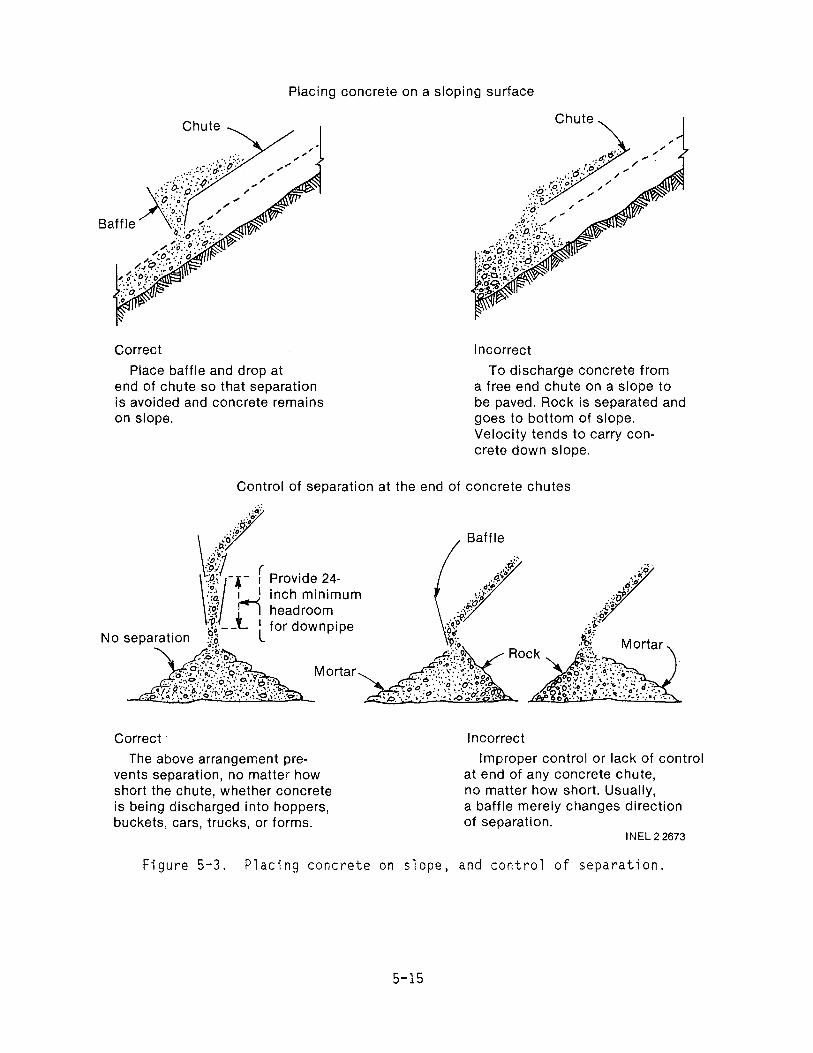
Placing concrete on a sloping surface
ChuteChute
Correct Incorrect
Place baffle and drop at To discharge concrete from end of chute so that separation a free end chute on a slope to is avoided and concrete remains be paved. Rock is separated and on slope. goes to bottom of slope.
Velocity tends to carry concrete down slope.
Control of separation at the end of concrete chutes
Baffle
Correct· Incorrect
The above arrangement pre Improper control or lack of control vents separation, no matter how at end of any concrete chute, short the chute, whether concrete no matter how short. Usually, is being discharged into hoppers, a baffle merely changes direction buckets, cars, trucks, or forms. of separation.
INEL 2 2673
Figure 5-3. Placing concrete on slope, and control of separation.
5-15

I.(;)
0
o c. 0
o ~
J -I1
. .1"
~ t~ I
'. ·0 @
.I). 0
\e9
@Io.
0 I~7-0
0 @ o 0
( . ~ • I). 0
() . .. ~ .Q ' \!' .. : . 0; OJ''
0 !D ... ::
•. i::>
o D··IIIP.t· 0
- (\8.1~
~ Drop chute built into forms
/ Separation Pocket
Drop chute to moveable pocket or opening in form
.0;, o·
1. .,. ~
\) ~
\) til ..
Correct
Drop concrete vertically into outside pocket under each form opening so as to let concrete stop and flow easily over into form without separation.
Figure 5-4. Placing concrete in
Incorrect
To permit high velocity stream of concrete to enter forms on an angle from the vertical invariably results in separation.
INEL 2 2668
forms.
5-16

Placing concrete in top of narrow form
·1 ' " .' ~ " " ,0
'I .: ,: 'I.~:'.~ '\.' .
" ", \.1': "0,, I -,,"., •• ~ •• Q •
~ Chute or )1-/ wheelbarrow
Correct
Discharge concrete into light hopper feeding into light flexible drop chute. Separation is avoided, Forms and steel are clean until concrete covers them.
Figure 5-5. Placing concrete
/ Chute or ./,,-" wheelbarrow
Incorrect
To permit concrete to strike against form and ricochet on bars and form faces causing separation and honeycomb at the bottom,
INEL22671
in top of narrow form.
Correct
To dump concrete into face of concrete in place.
Incorrect
To dump concrete away from concrete in place.
INEL 2 2670
Figure 5-6. Placing slab concrete.
5-17

Correct Incorrect
Start placing at bottom of To begin placing at top of slope so that compaction slope. Upper concrete tends is increased by weight of to pull apart, especially newly added concrete as when vibrated below. vibration consolidates.
When concrete must be placed in a sloping lift
o. " .1 ....6 .' 0 '1'.1" . 0 ' .. ~'.I O· o· 0 ','.1' Q' .' .' ,1.1' 0 ", 1.1· .. ···. I']:" o ..0 1'1'.. . 0 ' 0 I ,.I . o' (J. ~!' i . 0 : ,·'0 ... ·'01· D' .... 101 ... "0 '1°1. ' , .....,.,... I I. ' ". ',0<::>', . (J., .1 . () . V\), i' j 0 (') , I . 0'.--.:...- -----rr-----+,t-
l."~ ,. I .' / .I, . 0 0 '" <;:; () " . , • \ . .
Ifob. 0 '< ~ :O.D:":;OO~60 .... ~:.
f( 0'. • \.1 ~ "0 ,,1:1...• ......., -\.' , .'
. 0 1.1 , ., / . O· .. 0 . \ ' \ () . 0'., .1 " I ./ . . . . \. \ ' .. .. I. I .. I I ....• '0' . \' \' . o ~l '., .0,,/.:1.'" :' C:)C~. .,0 \. " '0'
• 'c.)·.,t..J o : '.0" ·..;o·.·.eJ·D~-:"~ e;, " . ()' 0.. 0" . 0 .. ',' 0 I '. . ~.'.., ~ . .' ,. '. , " .
Correct incorrect
Vertical penetration of Random penetration of vibrator a few inches into the vibrator at all angles previous lift (which should and spacings without not yet be rigid) at system sufficient depth to assure atic regular intervals, monolithic combination of
the two layers.
Systematic vibration of each new lift
Shovel rocks from rock Attempting to correct rock pocket onto a softer, pocket by shoveling mortar amply sanded area and and soft concrete on it. tramp or vibrate.
Treatment of rock pocket when placing concrete INEL 2 2669
Figure 5-7. Compaction with vibrators, and treatment of rock pocket,
5-18

New concrete can be bonded to old by wetting the old surface, plaster
ing it with neat cement (a mixture of cement and water), and pouring the new
concrete before the neat cement has set. Where two surfaces adjoin and one
will be poured and allowed to harden before pouring the second, rubber water
stops designed to waterproof joints should be installed in the first pour.
5.2.2.2.5 Air Entrainment--The entrainment of air using resins
or other air-bubble-forming compounds gives the concrete somewhat greater
plasticity and freedom from segregation, and increases its durability
against freezing and thawing. Although the added resins and the resulting
air voids reduce the strength of the material, the greater workability of
the air-entrained mixture allows a reduction of water content and a higher
ratio of course aggregate to fine, thus compensating for any loss in
strength.
5.2.2.3 Concrete Forms. Concrete to be placed for slabs, walls, or
columns must be supported in forms. The purpose of the forms is to contain
the concrete until it has the strength to stand by itself and to prevent
leakage that will cause the concrete to honeycomb. It is important that the
forms have sufficient strength and rigidity to prevent bulging or sagging,
which will permanently damage the structure. The pressure on the forms is
equivalent to that of a liquid with the same density as concrete. The forms
should be left in place 7 days for vertical walls and 28 days for a support
structure.
The forms should be checked for line and grade when they are placed.
The interior surface of the forms must be smooth and tight at joints to give
a clean finish to the concrete. All dirt, shavings, and other debris should
be removed from the forms. Wood forms should be drenched for 1/2 hour or
more before placement of concrete, since swelling of dry forms in contact
with wet concrete may distort the form. Forms that are reused should be
thoroughly cleaned and oiled. A light oil should be used, and any excess
should be wiped off to prevent staining the concrete surface.
5-19

Stability is an important consideration in construction of forms. If
there is any movement of the forms as the concrete is poured, all work
should be stopped and the problem corrected. Some common deficiencies
resulting in form failure are:
Inadequate cross-bracing of the shores
• Inadequate horizontal bracing and poor splicing
Failure to regulate the rate of concrete placement
Poor regulation of the horizontal balance of form filling
Unstable soil under the mud sills
No provision for lateral pressure
Inadequate bracing for wind pressure
Vibration from adjacent moving loads
Nearby embankment slippage.
If vibrators are to be applied to the outside of the form, it is
essential that the forms be sturdy enough to prevent misalignment or other
damage from this added stress.
5.2.2.4 Concrete Reinforcing Steel. Reinforced concrete is a combi
nation of steel and concrete fabricated into a structural member. Concrete
is weak in tension, and steel bars embedded within the concrete provide the
needed tensile strength. The concrete protects the steel against corrosion
and fire damage. The concrete adheres to the surface of the bars, and lugs
on the bars also anchor them in the concrete. This gripping action,
referred to as a bond, keeps the bars from slipping through the concrete so
that the concrete and bars act as a single unit.
5-20

Rcinfci_ing steel is available as single bar lengths or «ire mesh. In
light gages, wire mesh is available in rolls and is common for building con
struction. Large sheets of heavier gages are used for highly loaded slabs.
The wire mesh is furnished in square or rectangular patterns welded at each
intersection. A 4-inch-square mesh will greatly enhance a slab's durability
and resistance to cracking. If lighter gages are used, the concrete will
tend to push the wire to the bottom of the form. A hook tool should then
be used to pull it back up into the concrete after the concrete has been
tamped and before troweling the surface. The wire should be pulled up about
1 inch from the bottom of the form.
Single bar reinforcing steel is used for walls, columns, and the equip
ment pad. Reinforcing bars come in many sizes and several grades.
Table 5-1 gives the available sizes of bars, and Figure 5-8 shows the vari
ous grades with identification marks. The grades refer to the different
strength properties of the materials from which they are fabricated. For
microhydropower applications, any of the grades should be acceptable.
TABLE 5-1. ASTM STANDARD REINFORCING BARS
Designation ~1 n (lb/ftl Diameter
#3 0.11 0.376 0.375 #4 0.20 0.668 0.500 #5 0.31 1.043 0.625 #6 0.44 1.502 0.750
#7 0.60 2.044 0.875 #8 0.79 2.670 1.000 #9 1. 00 3.400 1. 128
#10 1. 27 4.303 1. 270
#11 1. 56 5.313 1. 410 #14 2.25 7.650 1. 693 #18 4.00 13.600 2.257
5-21
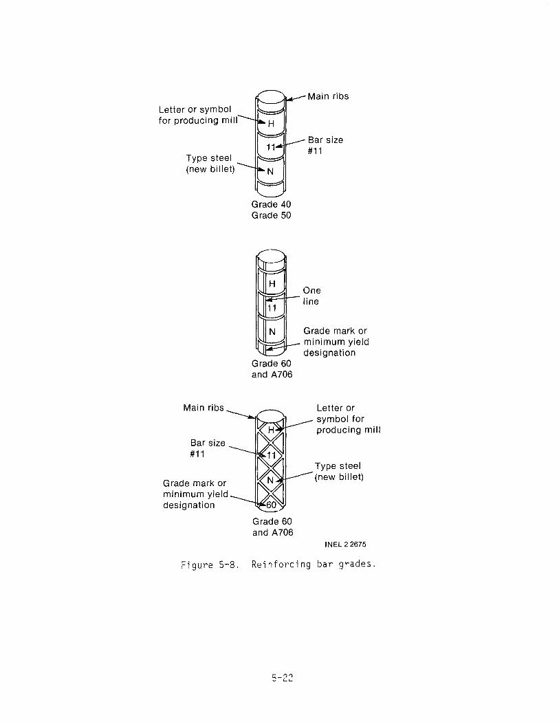
Letter or symbol for producing mill
Type steel (new billet)
Main ribs
Bar size #11
Grade mark or minimum yield designation
Figure 5-8.
Grade 40 Grade 50
r=:..u-
Grade 60 and A706
Grade 60 and A706
Main ribs
Bar size #11
One line
Grade mark or minimum yield designation
Letter or symbol for producing mill
Type steel (new billet)
INEL 2 2675
Reinforcing bar grades.

The proper embedment of the bars in the concrete is important to tne
strength of a reinforced concrete member. The minimum standards shown in
Figure 5-9 can be used when the embedment has not been specified on a draw
ing. The exact positioning of the bars in relation to one another is gen
erally not as critical as the embedment as long as the number of bars called
for used. The amount of steel bar used should be determined by a technical
person if the structure is to be heavily loaded and unsupported over a long
distance. If you are not familiar with the placing of reinforcing bar in
concrete, seek help in determining the bar size and placement. If the
equipment pad is to be placed on the ground, No.4 rebar on I-foot centers
should provide an adequate mounting pad.
Once the bars have been placed, they should be securely held in posi
tion by wiring or welding the bar intersections to avoid displacement during
pouring. This wiring or welding of the bars only provides stability; it
adds nothing to the strength of the structure. The number of intersections
that must be tied or welded is a matter of judgement, but it should be suf
ficient to secure every intersection around the periphery and every third
or fourth intersection in the interior. Methods for tieing bar inter
sections are shown in Figure 5-10. If the bars are welded at the inter
sections rather than tied, the slab and bar can serve as an electrical
ground through a lead from the bar to the generator ground system.
Additional information on the placement of reinforcing bar can be found
in Reference a.
5.2.2.5 Anchor Bolts. Anchor bolts to mount major equipment should
be positioned before pouring the concrete for the equipment pad or power
house floor. If anchor bolts have not been set into the concrete, you may
have to chip out the concrete to install and grout the bolts in place. For
mounting small equipment, the concrete can be drilled to install concrete
anchors.
a. Manual of Standard Practice for Placing Reinforcing Bars, Concrete Reinforcing Steel Institute, Chicago, IL.
5-23

3 in. Outside face_ Inside face~I~
....... 3 in .
c::::!0~=o~=("\~=("\~=("\~=()~ ~
Footings f
#6 thru #18 - 2 in ...I~ _IL 'k in. min.
#5 & smaller - 11/2 in. 11/2 in.
Walls - #14 & #18
11/2 in.
Columns
Slabs
11/2 in. t
11/2 in.~ ~ Beams
Joists INEL 2 2672
Figure 5-9. Reinforcing bar embedment standards.
5-24

11 I----------------~=~----lr""/u
~-F-ig-.-A-------,i' Fig. C
I
Fig. B
INEL 2 2676
Figure 5-10. Me~hods for tieing reinforcing bar intersections.
The anchor-bolt size should be recommenced by the equipment manufac
turer. If the equipment must be leveled, leave an additional 1/2- to
l-incn length of bolt above the floor over the length needed for the
equipment base, nut, and washer to allow for shimming and grouting (see
Subsection 5.3).
A solid connection of the turbine-generator to the equipment pad is
essential. The mounting bolts poured into the pad must line up precisely
with the corresponding holes in the turbine frame. To ensure this alignment
and proper bolt depth, some turbine manufacturers supply a steel template
and mounting bolts. (A steel template can also be fabricated, if necessary,
once the exact spacing, depth, and bolt size is known.) Each bolt is
inserted in the corresponding hole in the template and held securely with a
nut. The steel template assembly is then cast into the equipment pad.
5-25

A less costly plywood template can also be used. A plywood template
is usually not cast into the slab, but used only to aid in placing the
mounting bolts. For plywood templates, two nuts, one above and one below
the template, are adjusted to hold the bolt at the proper depth.
If anchor bolts are poured into the concrete and protrude from the
floor, you will have to lift the equipment and place it on the bolts.
Therefore, heavy lifting equipment or other lifting provisions, should be
available in your powerhouse. If concrete anchors are used, the equipment
can be rolled or skidded into place and the bolts then installed and
tightened.
5.2.2.6 Penstock. To ensure tight joints, penstocks are typically
laid from the lowest elevation up. The pipe should be well supported even
in the bottom of the trench. Rocks should not be in contact with the pipe;
where rocks are a problem, the trench should be lined with sand or fine dirt
before placing the pipe. Straw can also be used to provide a bedding for
PVC or other plastic pipe. If steel pipe is used, a protective coating to
prevent corrosion shoJld be specified, and the pipe should not be bedded in
cinders.
The route of the pipe, whether it is above or below ground, should be
graded so that a channel for surface runoff is not formed. If the installa
tion is aboveground, remove nearby trees that could fall and large rocks
that could roll on the pipe. Do not backfill the penstock until it is
pressure checked for leaks (see Subsection 5.3). When all leaks have been
corrected, 6- to 7-inch layers of loose material should be placed and
lightly tamped until the pipe is covered by at least 6 inches of fill mate
rial. The remainder of the trench can then be filled all at once and the
site graded.
5.2.3 Mechanical Equipment
Most mechanical equipment will be installed and checked out after the
civil work is completed. The mechanical equipment work includes setting,
leveling, and aligning major equipnent such as the turbine-generator;
5-26

flushing and cleaning water passages; adjusting equipment for operation; and
lubricating newly installed equipment. In addition to the usual wrenches,
screwdrivers, and pliers needed for working on mechanical equipment, a hand
held tachometer, pressure gage, carpenter1s level, square, hydraulic jacks,
come-alongs, chain hoists, dial indicator, caliper, feeler gages, straight
edge, and torque wrench could be required. Plan to have needed tools
available.
5.2.3.1 Equipment Installation.
5.2.3.1.1 Positioning and Setting Equipment--The major equipment
to be installed in the powerhouse is the turbine-gener~tor set. In many
cases, this will be furnished assembled on a frame; lifting and positioning
of this item over the equipment pad can become 2 major obstacle if not
carefully planned. If the powerhouse has been designed with sufficiently
large doors, the entire unit can be lifted by a forklift and set into posi
tion. If this is not feasible, and the powerhouse overhead does not have a
beam capable of supporting the weight of the unit, a steel IIAII frame can be
constructed over the pad for lifting and pos~t10ning. If anchor bolts are
not protruding from the floor, the equipment can be pushed into position on
rollers made of pipe (3/4- to 1-1/2-inch d~ameter). Hydraulic jacks can
then be used to remove the rollers and lower the equipment into pos~tion,
If the turbine-generator set is furnished assembled on a frame, the
entire assembly must be leveled after it is positioned on the pad. If you
have poured the pad during construction of the powerhouse, the extra time
spent to ensure a level and smooth equipment pad will be time well spent,
and the frame need only be set on the pad and bolted down. However, if the
pad is not level, perhaps because an exis~ing builcing is being used, the
unit may have to be leveled and grouted in place. The frame should be
leveled with hydraulic jacks and metal shims placed between the floor and
frame for support. A nonshrinking grout cement, mixed according to the
manufacturerls directions, should then be forced under the frame to fill the
area on which the frame will rest. After the grout has dried, the nuts can
be placed on the anchor bolts and tightened to hold the unit in place.
5-27

5.2.3.1.2 Aligning and Adjusting Equipment--If the turbine, gen
erator, and drive system are purchased as separate units, you must attach
them to a frame. Separate components are lighter to handle during installa
tion, but some times a shaft alignment is needed. If a belt drive system
is used, the shafts of the turbine and generator will be parallel, and the
alignment is not as critical as with direct drive or gear drive systems.
For a belt-drive system, check the shaft alignment before bolting the gen
erator and turbine to the frame. Accurately measure the distance between
the shafts at the motor end; adjust to the same shaft distance at the outer
end by moving one of the components. A large caliper can also be used to
~easure the distance. To check vertical alignment, place a level along each
shaft, and shim the front or back of the components to raise or lower the
ends of the shafts as required. Securely tighten the component that will
not be moved to prepare for tensioning the belt.
The sheaves should then be placed on the shafts. Check the shafts and
keyways first to ensure that they are smooth and free of burrs. Wipe the
shaft, key, and sheave bore with light oil. Do not drive the sheaves on the
shaft; they should slip on freely. If the sheaves or keys do not slip on
freely, remove and check the size or correct the problem. Once both sheaves
are in place, tighten one and then place a straight edge across its face,
above the shaft. Slide the other pulley on its shaft until the sides of its
face evenly touch the straight edge; tighten it in this position. The
sheaves should now be aligned.
A properly designed belt system can be tightened by moving one of its
components, which will have elongated mounting bolt holes. When mounting
the belt(s) do not force it (them) over the sheaves; adjust the component
position to allow the belt(s) to slip on easily. Then tension the belts to
the manufacturer's recommendations and tighten the component mounting bolts,
making sure to maintain alignment as described above.
If the motor and generator are directly connected to one another or to
a gear box through couplings, the shafts of the components must be accu
rately aligned within the manufactureris tolerances to prevent excessive
wear on the shafts and bearings. If the couplings are flanges that are an
5-28

integral part of the shafts, the components can be brought together so that
their flange faces touch and then a feeler gage inserted between the flanges
at their periphery. Move each component and shim as necessary until the
flanges are flush with each other. Rotate the flanges several times and
check separation to ensure that the shafts are not at an angle to one
another. To determine if the shafts are in line with one another, a dial
indicator can be attached firmly to the outer diameter (rim) of one flange
with hose clamps (a bracket bolted to one flange with the dial indicator
attached is the most accurate method), and the pointer of the indicator set
on the outside diameter of the other flange. Rotate both flanges together
through 360 degrees to locate the point of minimum reading. Move or shim
one unit to bring this point to zero on the dial indicator. Repeat this
operation until the shafts are in alignment, then tighten all mounting bolts
and insert and tighten the coupling bolts.
If the coupling is not integral with the shaft but slides on the shaft
(such as the flange face coupling shown in Figure 4.9-1), the angular align
ment can be done more accurately with a dial indicator than with a feeler
gage. Separate the couplings enough so that the pointer of the dial indi
cator, attached as discussed above, can touch the face of the coupling
flange. One coupling is rotated through 360 degrees to locate the minimum
reading position. The units are moved to bring this reading to zero, and
the measurement is repeated. This procedure can be used with any of the
couplings where some separation between flanges is possible.
A reverse indicator method of alignment can be used when the couplings
are ribbed or otherwise unsuitable for the above alignment methods. Attach
a dial indicator firmly to the outside diameter of one shaft with hose
clamps, and place the pointer on the outside diameter of the other shaft.
Rotate the shafts in unison and determine the minimum reading. Move the
units to bring this reading to zero, and then repeat the procedure. Once
the first shaft is aligned in this way, remove the dial indicator, attach
it to the opposite shaft, and repeat the procedure to align both shafts.
Recheck the alignment by repeating the entire procedure.
5-29

5.2.3.1.3 Bolting--All bolts should be torqued to their required
loads. This procedure is important not only for bolts used for mountings
and couplings, but for those used for valves and flanges that prevent leak
age of water to the turbine. Bolts in circular patterns should be tightened
'~ernately from one side of the pattern to the other. Bolts in a straight
1 ne pattern should be tightened from the center of the line outward, alter
~at~ng from one side of the center to the other. First, tighten all bolts
to 75% of the recommended torque; then repeat the procedure, using the
alternating technique to bring all bolts to 100% of the recommended torque.
Torques for equipment bolts are normally supplied by the manufacturer.
If torque values are not provided for low-strength bolts, use the values
given in Table 5-2; for high strength bolts such as ASTM-A-325, ASTM-A
193 87, or ASTM-A-409, increase these values by a factor of 2 to 3.
5.2.3.2 Flushing and Testing Water Passages. Before turning water
into the system and before the penstock trench is backfilled, it is impera
tive that the entire system from intake to tailrace be checked. This
includes checking the gates and valves to ensure that they operate smoothly
TABLE 5-2. TORQUE VALUES FOR LOW-SiRENGTH BOLTS
Bolt Diameter Torque ( in. ) (ft-lb)
1/4 2 3/8 10 7116 18
112 28 9/16 40 5/8 55
3/4 100 7/8 160
1 250
1 1/8 340 1 1/4 490 1 1/2 850
5-30

without binding. Walk the canal and intake structure and remove all debris.
If everything is in order physically, the next step is to flush the canals
and intake structure.
Flushing clears the system of all loose material that could be washed
into the penstock and then into the turbine. This flushing will loosen and
remove the small particles and leave the larger, more stable rock. This
process is known as "armoring" and is an important preoperational step.
To flush the intake canal, close the slide gate or valve so that loose
material cannot enter the penstock. Flush the water and loose material
through the intake structure cleanout pipe. Be sure that the water path
below the outlet is riprapped to prevent erosion of the soil. Flush the
system for several hours, or as long as necessary to get it clean. This
flushing operation also provides a good opportunity to check that your stop
log frame or canal intake gates can regulate flow properly and stop flow
quickly.
When the intake is clean, flush the penstock. Open the penstock purge
valve and close the turbine isolation valve. Slowly open the inlet slide
gate or valve to the penstock intake. Water should flow into the penstock
and bypass the turbine. Whatever is in the pipe should go out the purge
valve. After flushing for several hours, slowly close the purge valve.
After the valve is closed, check the penstock for leaks. If no leaks are
present, drain the penstock and backfill where needed. After backfilling,
open the purge valve and then the headgate. Slowly close and open the purge
valve and check for signs of movement in the penstock. Increase the anchor
age and support of any section that is questionable.
5.2.3.3 Lubrication. Before operation, the turbine-generator and
other equipment should be lubricated according to the manufacturer's
requirements supplied with the units. Gear boxes should be filled with oil;
bearings and shafts should be greased to ensure smooth operation.
5-31

5.2.3.4 Equipment Checkout. The turbine-generator must be checked
out before it is energized. Auxiliary turbine-generator systems, such as
cooling or lubrication systems, should be checked out first to ensure that
they function in accordance with the manufacturer's instructions.
The turbine-generator can now be checked for rotation and vibration.
With the penstock purge valve open and the valve to the turbine closed, the
penstock headgate can be opened slowly. Allow water to fill the penstock
until it flows freely through the penstock purge valve, and then slowly shut
the purge valve. Check to be sure that the generator is not connected
electrically to the system, and then partially open the turbine inlet valve.
Because the generator is unloaded, the inlet valve should not be fully
opened under any circumstances or the turbine will quickly reach runaway
speed.
Once the equipment is rotating near design speed, a check for vibration
and shaft speeds can be made. A hand-held tachometer is useful to determine
speed. Accessable shafts and bearings should be checked for quietness of
operation. A screwdriver or metal rod firmly pressed against the bearing
housing will indicate rumbling or uneven operation that may be due to dirt.
A whistling sound is attributable to improper lubrication or insufficient
internal clearance. Unusual noises should be investigated immediately.
The temperature rise caused by bearing operation may make the bearing
housing too hot to touch. Bearings can operate to temperatures of 200°F and
greater without failure. If you suspect that the temperature is too hot,
consult the bearing manufacturer. Operating temperatures can be predicted
from the operating parameters of your site.
Make a manual check of the emergency shutdown system at this time to
ensure that it operates reliably.
Once all checks have been made, the system can be shut down: slowly
shut the turbine inlet valve, and then slowly open the penstock purge valve
and close the intake headgate.
5-32

5.2.4 Electrical
CAUTION: Electricity is Hazardous. As stated in Subsection 4.8.1, a
qualified electrician should help install the electrical system.
Before the electrical system is energized for the first time, it should
be inspected by an electrical inspector. In many localities, this inspec
tion will be a state or county requirement.
The electrical system can be constructed concurrently with other por
tions of the microhydropower system. The final connections to the genera
tor, however, cannot be made until the generator is permanently installed.
Some rules for the electrical installations are:
All conductors must be mechanically protected, or else routed at
such a height that they are not a hazard. Mechanical protection
can be conduit, metal raceway, or burial in the earth. Minimum
heights for overhead lines should be as specified by the National
Electric Code (NEC).
All conduits, boxes, equipment enclosures, and other electrical
equipment must be securely supported and anchored. Standard
installation procedures are to support all boxes and enclosures
independently. Conduits should be anchored every 8 feet on center
and within 3 feet of every bend or enclosure and as specified by
NEC.
All wire splices must be properly made and properly insulated as
defined by NEC.
All wiring connections to equipment must be made up tight.
CAUTION: Do not energize the system until all protective
equipment for that specified portion is installed.
5-33

• The electrical installation consists of connecting the generator
to the load through the overcurrent protective devices. These
pieces of equipment will be interconnected by the system wiring
and made ready for service.
• If the power system has a load control system, this system must
be set up, connected, and made ready for operation.
• If the power system interconnects to a utility system, the step-up
transformer and its protection equipment must be installed and
made ready for service. This work will usually be done by the
utility company and the cost billed to the developer. Even if the
utility does not perform this installation, close coordination
with them is required.
CAUTION: Do not connect to the utility's power line.
• When the generator has been permanently set and aligned, the
electrical system can be connected to the generator. The coils
of the generator will have to be interconnected to provide the
required voltage in accordance with the supplier's recommenda
tions. After the generator has been connected to provide the
voltage desired, it can then be interconnected to the rest of the
system.
• All system connections must be verified before the system is
energized for the first time. This should be done on a pOint-to
point basis. Any wiring diagrams that have been produced will be
helpful in this final checkout.
• Final connection to a utility line must be made by the utility.
The utility should be contacted and asked to proceed with any work
they have to perform. All disconnects must be left open at this
time.
5-34

6. STARTUP, OPERATION, AND MAINTENANCE
Once the completed microhydropower system has been checked out, start
up, equipment calibration, and steady-state operation are the next items of
concern. After the system has been placed in steady-state operation, a good
maintenance system must be implemented to ensure that the equipment will
give trouble· free operation.
6.1 Initial System Startup
Starting up the completed system for calibration and then steady-state
operation requires the following test instruments:
• Fuse tester
• Hand-held tachometer
• Volt-ohm-ammeter
• Clamp-on ammeter
• Pressure gage with an air purge valve.
6.1.1 Synchronous Generator Startup
If the no-load test run of Section 5 checks out as expected, then
startup and operation of the generator with a small amount of connected
electrical load can begin. The generator should not initially be started
fully loaded; it should be started with about 10% load and then incremental
loads added if smooth operation continues. Resistance loads that produce
heat will work best because they are steady and can be easily controlled in
small increments. If a load controller is being used in the system, you
should analyze it to determine what resistance can be used. If motor loads
exist, they should be disconnected during the low output testing of the gen
erator since sufficient power may not exist to operate them at their design
6-1

condition. This can be done by throwing the breaker in the panel. If you
are using a governor, review the manufacturer's data to determine at what
minimum load it will operate, and start there.
Slowly open the turbine isolation valve a small amount to generate the
10% load. The generator is loaded, and the system should run at its design
speed. The amperage meter should reflect the power being generated, and
both freq~ency and voltage should be right on specification.
Two or three frequency cycles either side of 60 Hz is acceptable, but
any more than that will require adjustment of the governor. A 10% system
load will depend on the size of the system. For a 10-kW plant, 10% will be
1 kW, or 1000 watts (about the load rating of one small baseboard heating
unit or a hand-held hair dryer). Larger plants will require correspondingly
greater converted loads to get to the 10% load level. Many homes powered
by microhydropower plants use electric heat, and these systems can be oper
ated so that the loads are connected in increments for testing purposes.
Once the system is operating well at the 10% load level, the load can
be increased. The power output will increase, but the frequency should stay
right at 60 Hz. There may be a momentary blip in frequency when the addi
tional load comes on, but that should last only a second or two until the
governor system compensates.
The frequency is a function of generator speed, and the governor or
electronic load controller will control either the power supplied by the
turbine or the electrical load on the generator so that generator speed and
frequency are maintained. Both hydraulic and electronic systems may require
some adjustment before they operate properly.
Specific operating instructions for governors should come from the
operation manuals for those units. Each has its own sequence for making
adjustments and fine tuning the system. Once the right set points are
found, mark the panel faces so they can be reset if moved.
6-2
Let the unit run at part load for 1/2 hour or more. Monitor tempera
tures of the generator and bearings for abnormal heat buildup. Listen for
any vibration that is more than a common type hum, and be aware of any
abnormal smells that could indicate excessive heat buildup or electrical
insulation problems.
Increase the electrical load on the generator gradually. The frequency
meter should remain at 60 ± 1 Hz, indicating that the governor is operating
properly. Heat and vibration levels should not change. As the load on the
generator changes, the speed of the turbine and generator should remain the
same. You can check this function by varying the load. The frequency meter
will show any problems by varying more than 1 Hz from the 60-Hz reading.
When you have the system operating at full output, note the way it
sounds and feels. Later, any change in those characteristics may indicate
that something is wrong. An intuitive sense of when it is running well will
be very helpful. It may be helpful in developing that sense to sit and
watch the unit run for several hours.
When one or more of the various protective devices such as governors
or load controllers (see Subsection 4.8.12) are included, they should be
activated to be certain that they work properly. Be certain that all oper
ators understand the operation of these devices and know how to reset them
if necessary.
The tachometer can be used to verify generator or turbine speed if
problems are encountered with speed control and frequency output. The
electrical instruments should be used to help adjust over current relays,
emergency shut down relays and circuit protective devices included in the
electrical control system.
6.1.2 Connecting Synchronous Generators to Utility Powerlines.
The utility's representatives should be present during initial startup
and synchronization of the generator to the powerline. Syncronous
generators are connected to active utility powerlines only after the gener
ator has been brought up to the frequency and voltage of the powerline.
6-3

Making a smooth connection to the powerline requires that certain prerequi
site conditions be met. The output voltage of the generator must be the
same as the powerline, the speed of the generator must correspond to the
frequency of the powerline, and the generator voltage must be in phase with
the powerline. In actual practice, there is some tolerance in these condi
tions. A slightly higher generator voltage when connecting to the powerline
does not cause any serious problem. At the instant the connection is made,
the two voltages are forced to be the same. Minor differences in voltage
are neutralized by the internal impedance of the generator, which will seek
a phase angle with respect to the powerline that brings the voltages
together.
Some minor difference in generator speed with respect to the powerline
is tolerable at the instant the connection is made, but immediately follow
ing closure, the generator speed becomes locked to that of the powerline.
Any appreciable difference in speed at the instant of closure will result
in a corresponding mechanical and electrical jolt to the system.
When the individual cycles of the powerline are exactly in step with
those of the generator, then the generator and the powerline are said to be
"in phase." It is only when the generator and powerline are in phase that
the generator can be smoothly connected to the powerline. This is roughly
equivalent to engaging two rotating mechanical gears. It is not sufficient
that the gears be rotating at the same speed to make a smooth engagement.
It is also necessary that the gear teeth be properly aligned at the instant
of engagement. If the generator and powerline are out of phase, the gener
ator is operated either faster or slower than the powerline until the two
systems are in phase. In actual practice, the speed of the generator is
adjusted until it is as near the frequency of the powerline as possible.
The speed of the generator, however, rarely remains precisely the same as
the powerline for more than a few seconds at one time. With this slight
difference in speed, the two systems will slowly wander into and out of
phase. It is necessary to observe the phase relationship and close the
connection to the powerline only at the instant when the two systems are in
phase.
6-4

The typical power plant has voltmeters to compare voltages of the two
systems and a synchroscope to determine the relative speed of the two sys
tems. A synchroscope is a round dial with a single pointer. The pointer
rotates at a speed which is the difference between the frequency of the
powerline and the generator. The pointer comes to a halt when the generator
is operating at the speed of the powerline; and the pointer points up when
the systems are in phase. In a typical plant, the pointer on the synchro
scope will not come to a complete halt until the generator is connected to
the powerline. After the connection is closed, the pointer will remain
fixed pointing upward. Counterclockwise rotation of the pointer indicates
that the generator is rotating more slowly than the powerline frequency, and
clockwise rotation indicates that the generator is rotating faster than the
powerline frequency. It is generally accepted that closure to the powerline
is best made with the pointer moving slowly clockwise and with the needle
slightly past the straight up position. This, however, is somewhat
dependent on the characteristics of the plant.
If the voltage, speed, and phase are correct, the generator is said to
be synchronized with the powerline, and connection to the powerline can be
made with no noticeable mechanical or electrical reaction. A mismatch of
voltage, speed, or phase when connection to the powerline is made will cause
a mechanical reaction and an electrical surge in the connecting lines. The
severity of the reaction will depend on the degree of mismatch. Closure of
the connection when the generator is 180 degrees out of phase is the worst
case situation. Such an event may result in an electrical surge that is
worse than short circuit and could do considerable damage to the generator.
A properly designed system will have protective equipment that should pre
vent damage from such an event by disconnecting the generator from the line.
Use of a synchroscope is one of several ways that can be used to syn
chronize the generator with the powerline. There is a very unsophisticated
method that uses lamps connected between the powerline and generator to
indicate phase and frequency and in a crude way voltage also. The lamps
blink on and off at a rate that corresponds to the difference between the
speed of the generator and the frequency of the powerline. When the lamps
stop blinking, the generator speed is matched to the powerline. Depending
6-5
on tne connection, the lamps will be full bright or totally darK when phase
and voltage are correct. Similarly, voltmeters can be connected so as to
react with the same pattern as the lamps. Combinations of lamps and volt
meters can also be used. A problem with t~is method is that both lamps and
voltmeters have reaction patterns that lag behind the true voltage being
indicated. However, such systems have been used very successfully.
Some equipment suppliers are supplying microhydropower developers with
solid-state equipment that senses when conditions are correct for closing
the connection to the powerline and automatically closes the switch. In
these installations, the operator adjusts speed and voltage. When condi
tions are correct, the system automatically makes the connection without
the need for a synchroscope.
With the generator connected to the powerline, load can be added by
increasing water flow to the turbine. As load is increased, it may be nec
essary to add excitation current if the generator has an external exciter,
but most small plants begin operation with an excess of exciter current,
which permits a wide range in generator load without need for adjusting the
exciter current. Self-excited generators are usually self adjusting. If
the exciter current is run too low, the power factor of the generator will
be low and the generator may pullout of synchronism.
For this type of installation there is little need for automatic speed
regulating equipment unless there are periods when the plant is to run
stand-alone.
Before three-phase generators are connected to a powerline, it is cus
tomary to check the phase rotation of the generator. It is possible to make
an error in the wire connections so that phase rotation is opposite that of
the powerline. Checking the phase rotation is usually done with a special
meter with leads that clip onto the three output leads of the generator.
The generator should come with sufficient wiring information to be able to
make the connections without error. However, it is a good idea to check
the phase rotation from the actual output voltages of the generator because
6-6
an error could cause damage to the generator. If a synchroscope is used on
the plant, incorrect phase rotation would be shown by the fact that it
would not function.
6.1.3 Induction Generator Startup
The startup of an induction generator differs somewhat from a synchro
nous generator. An induction generator is always connected to a utility
powerline, and so a utility representative should be present for initial
startup. The induction gener~tor should be energized momentarily to check
for correct rotation acting as a motor. Any reverse current relays will
have to be switched out of the control circuitry. If rotation is incorrect,
then a reconnection of the wires at the generator will correct the problem.
Once the generator has been wired to rotate correctly acting as a motor,
then it can be energized again to run as a motor.
While the generator is running as a motor, make calibration checks to
determine what the incoming power characterisitcs are on all phases. Look
for an imbalance in voltage between phases. A difference of ±5 to ±8% is
probably not abnormal, but more than 10% could indicate a problem on the
utility line.
Check the shutdown circuitry to ensure that it functions properly for
over- and undervoltage tripout, over- and underfrequency shutdown, reverse
current trip, etc.
After the shutdown circuitry has been checked and the relays have been
properly adjusted, the generator can then be energized again as a motor.
Once the unit is running smoothly, open the turbine inlet valve slowly while
monitoring the system ammeter. Remember, reverse current relays will be
switched out of the control circuit at this time. As additional water is
allowed to flow through the turbine, the ammeter will slowly decrease until
the synchronous speed of the generator is reached (no motor slip eXists).
Once the synchronous speed is exceeded, the generator begins to function not
as a motor but as a generator, and the ammeter now reads output instead of
input. The turbine inlet valve can be set for maximum generator output, and
6-7

the reverse current relays can be switched back into the control circuit.
The generator is now on-line, and the synchronization of the power output
from the generator is being controlled by the utility's system. With the
water running, check the shutdown controls again to ensure their proper
function.
6.1.4 System Troubleshooting
If your plant is not producing the power output for which you have
designed it, there are a few checks you can make before contacting the
turbine manufacturer. These data may help in understanding the problem.
pressure gage can be placed on a tap immediately upstream from the turbine.
This device can give the pressure at the turbine from which you can deter
mine your head. Check the pressure with the turbine isolation valve both
closed and full open while the turbine is fully loaded.
Use one of the methods discussed in Section 3 to check the flow in your
system while the turbine is running fully loaded. This can be done in the
intake structure or canal. The stop log structure could be used to fabri
cate a weir. With head and flow information available, you can discuss the
turbine problems with the manufacturer. The manufacturer will also need to
know the size of your penstock where the pressure measurement was taken in
order to calculate the velocity head at this point. If you are using a
reaction turbine with draft tube, the elevation from the pressure tap to the
tailwater level must be measured.
If the flow in you system is lower than predicted, check the trashrack,
intake structure, and waterways for obstructions. Review all of your cal
culations to ensure that you have not made a mistake. Observe your system
in operation. Ensure that the draft tube, if used, is always submerged to
prevent air from entering.
Compare the output of the generator with the calculated power from the
head and flow. Dividing the generator output by the calculated power will
give the efficiency of your system. Compare this with the predicted effi
ciency. If it is low, check the drive to ensure that it is functioning
6-8
properly, i.e. that the belts are not slipping. If all appears to be work
ing, have an electrician check the generator operation.
6.2 Startup
Normal operation of the system should be relatively trouble free.
Things that can cause shutdown include an interruption of water flow,
overheating of bearings, unloading the generator, overloading the
generator, a power surge due to lightning, and--if your system is con
nected to a utility--a power outage on their line or utility power being
out of specification for individual relay settings.
Startup procedures in a step-by-step sequence should be written down
and posted at the generator. If a shutdown has been caused by a loss of
water, or by bearing or drive problems, the startup procedure after the
water flow has been restored and problems corrected should be the same as
for initial startup. If an electrical problem has caused a shutdown, then
after investigation to determine the cause and corrective action as
required, the startup procedure should include bringing the generator up to
speed and resetting appropriate tripout relays.
Continue to monitor the equipment for excessive temperatures or vibra
tions. The powerhouse should be kept clean, and clear access around equip
ment and controls should be maintained. Electrical hazard warning signs
should be posted where appropriate, and electrical control boxes should be
kept locked or interlocks provided for foolproof tampering. The powerhouse
should be kept locked and a security fence provided.
An operational log is another useful tool to keep records on power
outputs, water flows, etc. This information can be useful in future plan
ning for plant upgrade, future power sales, and in plotting the cost of
operating the overall plant.
If your system uses an induction generator, there are two methods for
starting it. The first is the method discussed in the checkout procedure
6-9

where the generator is operated as a motor until it reaches synchronous
speed and then is overdriven by the turbine to generate power. This method
will cost money for the power to operate the generator as a motor.
The other method is to bring the generator up to synchronous speed
with the turbine. The generator is connected to the utility line and
overdriven by the turbine to start generating electric power. The speed of
the generator should be not greater than but very near to synchronous speed
when connected to the powerline. Since it is being started in the no-load
condition, you must be cautious in opening the turbine inlet valve to
prevent the unit from reaching runaway speed.
If your microhydropower installation is remote from your residence,
you should have instruments to remotely monitor the status of the plant.
These instruments may take the form of a single alarm that tells when the
plant has tripped off line. This is particularly true if it is tied into a
utility powerline so that loss of power would not be noticed at your resi
dence. The alarm would tell you when the system needs attention. Other
more detailed instrumentat"ion could be installed to allow you to monitor
specific operating characteristics of the plant, such as volts, amperes,
power, head, etc. Cables can be buried or attached to the power poles to
transmit this information to your residence.
6.3 Maintenance
Maintenance of a microhydropower plant is not complicated, but a con
stant effort should be maintained to ensure a trouble free plant. With
periodic maintenance, properly built systems should run for years without
major overhaul. Problems that arise because of mechanical failure, such as
burned out bearings or runner damage, should be repaired promptly to avoid
more serious damage. Hydropower plants are installed in areas where condi
tions are not ideal. Dust, dirt, and moisture are abundant, making good
housekeeping and regular maintenance a necessity.
A maintenance log is a good way to spot continuing problems that may
necessitate some system redesign, or to verify maintenance on items covered
6-10
by warranty. You should maintain such a log for your own information and
as a notice of when maintenance is due.
6.3.1 Manuals
Maintenance manuals should be obtained for all major equipment pur
chased. If you have bought used equipment, write the manufacturer for a
manual. Follow all directions in the manuals in servicing the equipment.
If manuals are not available, the general information given in the follow
ing sections provides guidance for maintaining equipment.
6.3.2 Waterways
Inspect the canals, penstocks, settling basins, intake structure, and
tailrace at least four times a year for signs of erosion, movement, or leak
age. Drain and inspect the underwater portions of the system at least once
a year. Concrete repairs can be made with an epoxy cement to cover exposed
reinforcing bar and seal damaged areas. Inspect the trashrack, gates, and
stop logs for damage, and repair if necessary. Clean debris from the water
ways and repair erosion of the earthen portions of the structures, or add
riprap.
Depending on your particular site, flush the settling basins and fore
bay as appropriate. Observe the quantity of settlement in these structures
to determine how often this must be done. If there are large quantities of
settlement, you may want to crack open the valve(s) on the system's flush
line(s) to allow a slow continous purge of these structures.
Another maintenance task that depends on the characteristics of the
stream on which your site is located is trashrack cleaning. This may be a
daily chore in spring when the stream is high and carrying a lot of debris,
in summer when moss is floating on the water, in fall when leaves from trees
fill the stream, or in the winter when ice builds up on the trashrack. The
cleaning of the trashrack is an area that must be attended to as often as
necessary to prevent loss of power generation. A trash rake should be kept
in the powerhouse to clean the rack.
6-11

6.3.3 Mechanical
Inspect your turbine once a year when you drain the system to inspect
the ~aterways, or follow the maintenance schedule in your manual. Inspect
the metal blades or buckets for signs of erosion. If the erosion is heavy
on these items, you may want to remove and repair them by welding. If ero
sion appears heavy every year, it could be a sign of problems in the design
of your system such as improper turbine setting. This is an area where help
should be requested from the turbine manufacture. Check the surfaces of the
spiral case, needle valve, draft tube, and wicket gates for damage, and
repair as necessary.
If the turbine has unusual vibration, check the bearing and shaft
clearances, the turbine blades or buckets, and the water passages. Turbine
vibration is an indication of serious problems and should be corrected
immediately.
Lubricate shafts and bearings at regular intervals. Manufacturers will
specify a lubrication period generally based on hours and type of service.
If there are no guidelines for greasing of equipment, you should probably
lubricate the bearings every 1200 to 2000 hours of operation. Wipe off any
grease that has leaked from around the seals onto the outer bearing sur
faces. Dirt will collect in thes~ areas if this is not done.
Gear boxes, hydraulic governors, and other equipment containing a res
ervoir of lubrication or working fluid should be checked every 3 months and
refilled if necessary. Use only the fluids recommended by the manufacturer.
Remove and clean filters for these systems yearly unless otherwise directed.
Check valve packings and flange joints for leakage. If leakage noticed
is not critical, replace the packing or gasket during your annual shutdown
of the water system. If leakage is excessive, shut the system down right
away and replace the packing or gasket. Test all manual and motor-operated
valves monthly to ensure proper operation.
6-12

Inspect the belt drive system every 6 months or when the unit is shut
down. Check the tension in the belts to ensure that they meet manufac
turers l recommendations. Belts tend to loosen with operation and should be
tightened periodically. Loosen the unit that is designed to take up the
slack and tighten the belts, making sure to maintain alignment. If you are
in doubt about the alignment, refer to Section 5 for aligning procedures.
Check the belts for cracks, tears, or worn areas. If you decide to
replace a belt because of a problem, replace all the belts on the drive at
the same time. Loosen the drive to remove and replace the belts. Do not
force the belts over the sheaves. Again, ensure that alignment is
maintained.
Clean the sheaves and belts periodically of dust, oil, and rust, which
reduce belt life and efficiency.
Review and check other mechanical equipment such as ventilation fans,
doors, or hoists, and oil and service as needed. Check and tighten bolts
and nuts on moving parts such as the sheaves on the belt drive, couplings,
shafts, etc. Anchor and mounting bolts and nuts should also be checked
periodically.
6.3.4 Electrical
A systematic and periodic inspection of the generator is also neces
sary. Most generators are located in areas where dirt can accumulate and
lower the insulation resistance. Some type of dust are highly abrasive and
can damage seals and bearings. Hence, it is desirable to clean generators
periodically. For severe conditions, weekly inspection and partial clean
ing may be needed. Most machines require a complete cleaning about once a
year.
At the annual inspection and cleaning, air-clean the generator using
moderate-pressure, compressed air (about 25 to 30 psi). On most ac genera
tors, this requires removing some of the protective covers.
6-13
On large machines, take generator insulation resistance readings peri
odically with a megohmeter. As long as the readings are consistent, the
condition of the insulation can be considered good. Low readings indicate
increased current leakage to ground or to other conductors, perhaps caused
by deteriorated insulation, moisture, dirty or corroded terminals, etc.
Inspection and servicing should be systematic. Frequency of inspection
and degree of thoroughness may vary and must be determined by the owner.
This will be governed by the importance of the produced power, the nature
of the service, and the environment. An inspection schedule must therefore
be elastic and adapted to the needs of each system. The following check
list, covering both synchronous and induction generators, is based on aver
age conditions insofar as dust and dirt are concerned. If your generator
manufacturer has not provided such a checklist, use this one as a guide.
POWER PLANT EQUIPMENT MAINTENANCE CHECK LIST
Check air inlets and exhaust screens for blockage or accumu
lated dust.
Check the voltmeter to see that the generator is running at
a steady voltage.
Check the frequency meter to see that the frequency is cor
rect and stable.
• Check for any unusual noise, vibrations, or temperature
changes in the bearings or casings on the turbine, generator,
and any gear boxes.
Week ly
Check oil level in bearings and gear boxes as appropriate.
Examine switches, fuses, and other controls.
6-14

Monthly
• Lubricate ball and roller bearings as recommended by the
manufacturer.
• Check for any leaking seals on all bearing housings.
Biannually
• Clean the generator thoroughly, blowing out dirt from wind
ings, and wipe commutator and brushes as appropriate.
• Check the brushes (if used), and renew any that are more
than half worn.
• Drain, wash out, and replace oil in the sleeve bearings (or
service as recommended by the manufacturer).
• Inspect and tighten any loose electrical connections on the
generator and control section components.
• Examine the drive system critically for smoothness of run
ning, absence of vibration, and worn gears, couplings, or
belts.
• Check anchor bolts, end-shield bolts, pulleys, couplings,
gear and journal setscrews, and keys for tightness.
• Observe that all covers, belts, and gear guards are in good
order, in place, and securely fastened.
Annually
• Clean out and replace the grease in ball- or roller-bearing
housings (or service as recommended by the manufacturer).
6-15
• Test generator insulation with a megohmmeter.
• Check clearance between the shaft and journal boxes of
sleeve-bearing units to prevent operation with worn bearings.
• Clean out undercut slots in the generator commutator if
required.
• Examine connections of the commutator and armature coils.
• Inspect the armature bands.
6.4 Safety
Post warning signs to explain the correct operation of valves, elec
trical switches, and test eqipment. Provide a fuse puller for replacing
fuses, electrical interlocks, and keyed safety bypasses. Keep the equipment
pad clean and free of water. Protect electrical equipment from water. Keep
a fire extinguisher rated for electrical fires in the powerhouse. Provide
guards on all moving equipment such as belts and shafts. Provide guard
rails around the intake and cleanout areas if falling into them would be
hazardous.
Provide security fences around the powerhouse and transformer pad as
well as the intake structure. Locks to prevent unauthorized operation of
bypass valves and the headgate are also good safety precautions.
Provide an emergency shutdown switch at the generator to shut the tur
bine and electrical system down. This switch should be used only in emer
gency situations and should be labeled as such.
6.5 Spare Parts
The powerhouse should be stocked with spare parts for the power plant.
Many sites will be located in remote areas where the availability of parts
6-16

is limited. Review the manufacturers literature to determine what spare
parts are recommended. Additional item that should be kept are:
• Fuses
• One set of belts
• Valve packing
• Gasket material
• Bearings
• Lubricants
• Valve trim (seats, plug, disk, etc.)
• One section of trashrack
• Generator brushes.
6-17


7. ECONOMIC AND FINANCIAL CONSIDERATIONS
Economic and financial considerations are an important aspect of evalu
ating the potential use of microhydropower. Accordingly, the following
section details some economic and financial concerns. The section is
divided by developer categories. The Category 1 developer is discussed
first, and the Category 2 developer is discussed second. For a detailed
discussion on how to prepare an economic analysis, see Appendix A-5.
7.1 Category 1 Developer
Category 1 developers are unique because their primary motive for
operation is to supply energy for their own needs. The market for this
energy is identified and quantified. This situation may occur in remote
areas not presently served by electrical utilities or where present
electrical needs are served with small fossil-fueled generators.
To perform an economic analysis, you must first estimate your current
power consumption and identify its cost. Assume, for example, that you
have identified your needs at about 64,000 kWh per year, i.e. you need a
15 kW unit. You have three options: purchase the required electricity
from a utility, generate your own power with a gasoline-fired generator, or
install your own microhydropower unit.
Electricity purchased from the utility currently costs $3200 per year
at 50 mills per kWh, or 5¢ per kWh. This dollar amount assumes extra
charges for peaking, transmission hook-up, etc. This cost is highly
geographically dependent.
The gasoline-fired generator has a capital installed cost of $5000 and
will require $4,670 per year to purchase gasoline for operation. One gallon
of gasoline will generate 13.7 kWh. Therefore, 64,000 divided by 13.7
equals 4670 gallons per year; at $1.00 per gallon, the cost is $4,670.
7-1

The microhydropower unit (15 kW) will cost $22,500 if $1,500 per kW is
used as an estimate. Operating costs can be estimated at 1% per year of
capital costs, or $225.
Annualizing the costs of the installed equipment over a 15-year life
cycle results in $1500 per year for the microhydropower unit and $333 per
year for the gasoline-fired generator. The following table shows these
costs for Year 1.
TABLE 7-1. COSTS FOR YEAR ONE
Gasoline-Fired Utility Generator Microhydro2ower
Annualized Cost -0 333 1500
Operating Costs 3200 4670 225 in Year 1
Total Costs 3200 5003 1725
Clearly, the microhydropower unit holds an economic advantage. Because
gasoline prices and electricity prices fluctuate with inflation, the cost
per year will not remain constant over the 15-year life cycle. Hence, an
escalation factor must be used to determine the annual costs at the end of
the 15 years. Using 6% per year escalation on all costs subject to infla
tion, i.e., operating costs, the following cost table can be prepared with
the escalation formula:
Where
= Future value
= Present value
7-2

that your project presents an acceptable risk. The more risk that you can
remove from the lending institution, the lower the interest rate you will
pay.
The greatest risk for a microhydropower development is the sale of the
power. That is why it is essential to work out a contractual agreement
with the utility company. Another risk is that the project may not operate
at its designed capacity. Professional engineering services will lower
this risk. Another risk is that the expected revenue will be less than
anticipated. This could happen for several reasons. The water flow could
be below normal, the equipment may require more shutdown time than antici
pated, or the rate paid by the power purchaser may fall below forecast.
The contractual agreement with the power company will lessen this risk.
The risk level assigned to your microhydropower development by a lend
ing institution will be primarily a function of that institution's percep
tion of your capacity to repay the loan. The institution's previous
experience with you and collateral other than the hydropower site are
important considerations. To obtain a loan, you must present the bank with
a sound business plan as well as a sound technical plan. If you prepare
these plans without professional assistance, you must be prepared to
demonstrate to the bank that you are qualified to prepare them.
The business plan should contain the necessary permits and licenses.
All construction costs should be identified. Wherever possible, provide
vendor quotations and contracts. This lessens the risk of underestimating
the projectis total cost. The business plan should also contain realistic
projections of the project1s revenues and operating costs over a period at
least as long as the proposed term of the loan. This projection must show
that the project can afford the loan payments. However, as a minimum you
should be able to demonstrate that the annual revenues less the annual
operating costs exceed the debt service (i .e., interest and principal loan
payment) by at least 25% during the entire life of the loan. This is
called a 125% debt service coverage.
7-6

Bank financing may be available for Category 2 developers. However,
previous experience indicates that the key to arranging the financing is
the contractual agreement between the utility company and the developer.
Commercial banks typically offer construction loans on a short-term basis,
with the long-term financing available when the project is complete.
Although this appears to be two separate loans, they are generally
negotiated at one time, i.e., prior to construction.
Another possible source of financing is the Small Business Administra
tion (SBA). This is usually an excellent source of financing for any small
business. And, this source should definitely be pursued if the developer
appears fi nanci ally "thi n. II Thi s means that the fi nanci a 1 statement of the
developer does not meet the minimum requirements of the lending institution.
This minimum requirement is usually that income, less expenses, allows for
1-1/4 times the payment of principal and interest.
You may want to investigate a limited partnership. Limited partner
ships can be formed with the aid of an attorney. They generally are struc
tured as a tax shelter in an effort to pass along tax advantages from the
developer to other persons who want the tax savings. The developer becomes
the general partner and usually contributes a 10% equity share. The limited
partners contribute the other 90% of the equity. This is a fairly complex
source of financing and requires legal counsel.
Microhydropower presents some risk in development. It is important
before securing financing to understand the risk-return tradeoff.
In general, an institution expects higher returns for accepting greater
risks. For example, oil companies risk millions of dollars to drill a well
that may never produce. But if they strike oil, their returns are extremely
high. Lending institutions such as commercial banks are risk-averse. As
risk increases, they charge higher interest rates. At some point the risk
becomes so great that they will not even participate in the loan. If you
intend to use any debt financing, you must convince the lending institution
7-5

These estimates along with a financial statement of the deve,opt.:' will help
initiate discussions about financing. The preparation of these estimations
is presented in Appendix A-5.
7.2 Category 2 Developer
The critical factor for Category 2 developers is to contact the utility
company serving the area and work out a contract for the pur~hase of the
power. This market element is essential to the successful completion of
the project. Because of recent legislation, the utility company, either
public or private, may be willing to negotiate a contract. The utility may
also be helpful in obtaining permits, obtaining financing, and obtaining
engineering advice.
In determining the economics of the potential site, a complete analysis
of capital equipment costs is a prerequisite. Also, the potential revenues
and operating costs must be identified and estimated with the help of the
utility district. Alternative methods of securing the power should be
evaluated. The mechanics of preparing a cash flow analysis, benefit-cost
analysis, simple payback, and a sensitivity analysis are detailed in
Appendix A-S.
Financing options may be limited. The utility company will know the
potential financing options acceptable in a particular area.
Basically, the two kinds of financing available are debt and equity.
Debt financing places a contractual obligation on the developer to repay
the loan in accordance with the loan terms. Equity financing is the amount
of collateral, cash, or services the developer uses as his down payment.
This debt-equity arrangement is similar to a home mortgage where the down
payment is the original equity and the debt is the amount borrowed. Because
hydropower tends to be capital-intensive, the debt fraction is generally
quite high. "Capital-intensive" means that the original cost of equipment
and installation are much higher than the operational costs.
7-4

r = Escalation percent; 6% = 0.06
n = Number of years.
TABLE 7-2. COSTS IN YEAR FIFTEEN
Gasoline-Fired Utility Generator MicrohydroQower
Annualized Cost -0 $ 333 $ 1500
Operating Costs 7,669 11,192 539 in Year 15
Total Costs 7,669 11,525 1,839
Again, the microhydropower unit holds the economic advantage.
Financing alternatives for the Category 1 developer may be limited,
but some suggestions are presented. The first and most widely accepted
suggestion is the power company. Public or private utilities may find it
beneficial to finance 50% or less of the project, depending on how costly
it would be to install service to the area. Bank financing should also be
pursued. A second mor~gage on the property or a loan secured by other
collateral may be obtainable through your commercial bank. In some cases,
a line-of-credit extended for farm operations could be used to finance the
microhydropower development. Another alternative is the equipment manufac
turer. They may have some financing arrangements available; however, this
may be very costly in interest charges. Finally, the Small Business Admin
istration (SBA) should be contacted if a business is involved. More elab
orate financing mechanisms such as limited partnerships set up for tax
shelters may be too complicated and costly for tne very small developer.
The requirements necessary before going to any lender would be a
capital cost estimation, revenue estimation, and operating cost estimation.
7-3

The most uncertain projection in the business plan is likely to be the
project's annual revenues. As previously mentioned, the marketing arrange
ment is closely related to the financing alternatives available. You can
significantly reduce the bank's risk by presenting a power purchase
contract. Most banks will not consider the loan without such a contract.
The degree of security a bank assigns to a power purchase contract will
depend on the reliability of the purchaser and the terms of the contract.
The most secure arrangement for the bank would be a "Hell-or-high-water"
contract with a major utility. Under such a contract, the utility would
agree to make annual payments to you whether or not your microhydropower
site operates as designed. In negotiating this contract, risk is trans
ferred from you and the bank to the utility. In return for accepting this
risk, the rate offered by the utility will be lowered. This type of con
tract represents the greatest security to the bank and the smallest return
to you. At the other extreme, you and the utility could negotiate a con
tract for the utility to purchase power at the negotiated rate. Because
this rate can be volatile, such a contract presents a greater risk to the
bank. To compensate for increased risk, the bank may lend a lesser amount
for a shorter period of time at higher interest rates than if you had
negotiated a "Hell-or-high-water" contract.
The revenues projected in a business plan can be lower than the
revenues that you actually expect to receive. For example, you may expect
your revenues to escalate by 8% per year as the price of energy increases
with inflation. You may consider this an acceptable risk and base your
expected return on it. However, a lending institution would find such a
risk unacceptable if their debt service depended upon it. An acceptable
risk to a bank might be on the order of I'current rates will not decrease
over the term of the loan." When you and the lender have different percep
tions about the project's future, the lender's perception will dominate the
loan negotiations. It is for this reason that it is best to have a
long-term power purchase contract.
7-7


8. LEGAL, INSTITUTIONAL, AND ENVIRONMENTAL CONSIDERATIONS
This section focuses on the many local, state, and Federal laws that
apply to microhydropower development, the regulations that are involved,
and the problems that must be addressed in getting the certifications,
permits, and licenses or exemptions necessary to proceed with construction
of a microhydropower project. The fact that microhydropower developments
are very small and may cause very little impact does not, in most cases,
exempt the developer from complying with these laws and regulations.
Fortunately, there is an ongoing effort at all levels of government to
simplify the licensing procedures for microhydropower developments.
The process of obtaining the necessary permits and licenses or
exemptions for any hydropower project should always be started at the
beginning of the project. A systematic approach to licensinga will
greatly reduce the time required and minimize the pitfalls encountered.
This systematic approach should begin with the initial agency contacts.
The key agencies in the licensing process should be alerted early to the
proposed project and asked for information on the prerequisites for their
specific permits, certifications, licenses, etc. The developer must deal
with three levels of government: local, state, and Federal. Normally, all
three levels must be fully satisfied before construction can begin. At the
local level, the developer must comply with county, township, or municipal
planning and zoning regulations. Especially where urban development has
surrounded an existing dam, it is important to make sure that a generating
facility is acceptable under applicable codes. A building permit and
possibly other local p~rmits are needed to build or refurbish a
microhydropower development. Normally, cognizant state agencies and the
Federal Energy Regulatory Commission require compliance with local laws
before issuing their respective licenses.
a. As used here, the term IIlicensing" includes all permits, licenses, certifications, letters, and exemptions necessary for a project.
8-1

At the state level, at least a water right permit, a water quality
certification, and a general environmental certification are necessary.
A variety of other state permits may be required, depending on the specific
s1te.
The Federal Energy Regulatory Commission (FERC) is the agency
responsible for licensing at the Federal level. Where a microhydropower
project does not involve Federal land, a navigable stream, or an upstream
Federal water project, submitting copies of the state permits and
certifications along with the appropriate FERC exemption or license form is
generally adequate. Where Federal lands, a navigable stream, or an
upstream Federal water project are involved, additional permits are needed
from the appropriate Federal agencies. In a few cases involving private
onsite energy use and a private water source, an FERC license will not be
necessary. However, this special case should always be cleared with the
FERC to avoid any later problems.
Because reouirements vary widely from site to site and from state to
state, it is not possible to present a generally applicable step-by-step
procedure for obtaining all the necessary certifications, permits, and
licenses or exemptions. Therefore, this section discusses considerations
that affect the licensing process and the various requirements encountered
at the various levels of government, and then presents a general discussion
of procedures for licensing the two example sites used in this handbook.
8.1 Environmental Considerations
Environmental considerations affecting microhydropower development and
operation are very site specific. The general guidelines outlined in this
subsection are intended to acouaint the developer with most of the issues
that should be addressed. In most areas, local, state, and Federal
agencies can be helpful in identifying potential ecological concerns.
Following is a partial list of such agencies:
Federal Fish and Wildlife Service
8-2

• State Fish and Game Department
• Federal Environmental Protection Agency
• State Department of Environmental Resources
• State Health Department
• National Historical Society
• Army Corp of Engineers
• Soil Conservation Service
• County and university extension services.
Generally, a developer can expect better cooperation from the
appropriate agencies if initial contact is made early in the planning
stages of a project. These early contacts can provide the developer with
valuable information on stream characteristics and on previously overlooked
adverse environmental impacts that could block the project.
Environmental considerations development are different during the
construction and operation phases of a microhydropower project, although
some overlapping does occur. Therefore, the two phases are considered
separately.
8.1.1 Environmental Considerations During Construction
Environmental concerns during microhydropower project construction
fall into five broad categories:
• Water quality
• Diversion of stream flow
8-3

Sediment control and dredging
Wildlife and migratory fish
Historical significance and aesthetics.
8.1.1.1 Water Quality. Water quality concerns during
microhydropower project construction usually involve turbidity (see
Subsection 8.1.1.3) and changes in nutrient loading, temperature, and
dissolved oxygen values. Regulations and standards governing these
parameters vary considerably depending on the type of watershed and its
uses. Contact a local office of the U.S. Environmental Protection Agency
(EPA), the state agency concerned with water quality, or an appropriate
local agency or county extension service to determine what regulations are
applicable to the proposed development.
8.1.1.2 Diversion of Stream Flow. During construction, you may have
to divert part or all of the flow in a stream. If such action is necessary,
there are usually several options that you can employ (i .e., construction
during low flow periods or winter months, temporary dikes, etc.) to
minimize any adverse environmental effects. State and local agencies and
county extension services can usually help in outlining these options.
8.1.1.3 Sediment Control and Dredging. Dredging operations and
sediment control during construction are an important problem that must be
addressed. Before starting construction, consider what actions are
necessary to control erosion and minimize sediment transport from all
disturbed areas (e.g., access roads, equipment site, transmission lines,
etc.). The Soil Conservation Service, as well as other agencies, can be
very helpful in outlining plans with the developer.
Dredging of existing channels or impoundments can result in increased
nutrient loading and decreases in dissolved oxygen in the water. Materials
that have settled to the bottom of a stream are often subject to a reducing
environment caused by a lack of oxygen. This condition can result in a
buildup of toxic elements that may cause adverse environmental effects if
8-4
the settled material is put back into suspension. If these conditions are
present, you may require special permits to dispose of the dredge material.
8.1.1.4 Wildlife and Migratory Fish. During the planning stage of
any microhydropower project, contact the appropriate fish and wildlife
agencies to ensure that the proposed project will not affect any threatened
or endangered species. If migratory fish species occupy the watershed,
schedule construction of the project to minimize any conflicts. State and
Federal agencies can help in protecting sensitive areas and providing
suggestions for restoring areas that have been disturbed.
8.1.1.5 Historical Significance and Aesthetics. During the project
planning stage, contact the appropriate state agency and check the National
Register of Historic Places to ensure that the proposed project will not
affect any protected historical or archeological site. At the same time,
bring any adverse impact on the aesthetics of the project area, including
proposed transmission lines, to the attention of the appropriate agencies
or planning commission.
8.1.2 Environmental Considerations During Operation
Environmental concerns during microhydropower project operation fall
into four broad categories:
Effects of water level fluctuations
• Instream flow requirements
Water quality changes
• Effects on migratory fish.
Some of the concerns addressed for the construction phase may need to be
considered again for the operating phase. Most of the following concerns
need to be addressed on a site-specific basis.
8-5

8.1.2.1 Effects of Water Level Fluctuations. Effects of water
level fluctuations are usually associated with man-made sources (e.g.,
impoundments) since run-of-the-river operations, by definition, do not
normally have significant adverse impacts. Potential impacts include: a
• Reduction in riparian habitat, vegetation, wetlands, and avian
nests
• Inundation of small tributaries
• Decreased stability of stream banks
• Decrease or loss of quality aquatic habitat and spawning areas
• Altered sedimentation patterns
• Stranding of fish and benthic invertebrates
• Disruption of fish migration
• Alteration of food chains
• Changes in algal communities.
8.1.2.2 Instream Flow Requirements. The instream flow requirement
may be the most significant issue associated with microhydropower
development. This term refers to the amount of water flow needed in a
natural stream or channel to sustain the instream values, or uses of the
water in the stream, at an acceptable 1eve1. b It identifies the flow
a. S. G. Hildebrand, L. B. Gross, Hydroelectric Operation at the River Basin Level: Research Needs to Include Ecological Issues in Basin-Level Hydropower Planning, EPRI WS-80-155, June 1981.
b. J. M. Loar, M. J. Sale, Analysis of Environmental Issues Related to ?ma11-Scale Hydroelectric Development V. Instream Flow Needs for Fishery Resources, ORNL/TM-7861, October 1981.
8-6

regime that will sustain all uses of water within the channel while
maintaining aesthetics and water quality. Water uses include support of
fish and wildlife populations, recreation, hydropower generation,
navigation, and ecosystem maintenance, which in turn includes freshwater
inflow to estuaries, riparian vegetation, and floodplain wetlands.a,b
You can·obtain the minimum flow requirements that must be met for
rivers and streams in many areas of the country from the Fish and Wildlife
Service and from state Fish and Game agencies. These requirements will
differ depending on changes in the flow regime patterns. For the
microhydropower developer, localized changes are the major concern, since
in many of the projects water will be diverted through a flume or penstock
to a generator at a lower elevation before being returned to the original
stream channel. Projects on the effluent end of liquid waste disposal
operations must maintain sufficient flow to ensure that the waste stream is
adequately diluted and that none of the water quality discharge standards
for the watershed are exceeded (e.g., dissolved oxygen, temperature, etc.).
Finally, because water used to maintain instream flow is usually not
available for power production, the potential energy that can be produced
by a microhydropower project may be less than expected. This is a major
concern since your microhydropower system may be faced with a mismatch
between energy demand and stream flow requirements.
8.1.2.3 Water Quality Changes. Water quality concerns that may be
an issue to the microhydropower developer include:
a. K. Bayha, IIInstream Flow Methodologies for Regional and National Assessment,1I Instream Flow Information Paper No.7, FWS/OBS-78/61, Cooperative Instream Flow Service Group, U.S. Fish and Wildlife Service, Fort Collins, Colorado; unpublished report, 156 pp, 1978.
b. P. S. Wassenberg, S. Olive, J. L. Demott, C. B. Stalnaker, IIElements in Negotiating Stream Flows Associated with Federal Projects," Instream Flow Information Paper No.9, FWS/OBS-79/03, Fort Collins, Colorado, 41 pp, 1979.
8-7

• Changes in nutrient transport and ~ycling
• Altered temperature regimes
• Altered dissolved oxygen regimes
• Altered material cycles, including trace elements, heavy metals,
and organics.
The most subtle changes to consider are possible secondary impacts on
biological components of impoundments and tailwaters.
8.1.2.4 Effects on Migratory Fish. The issue of fish migration is
perhaps the most obvious ecological concern in most hydropower
developments. An improperly designed microhydropower project can block the
downstream migration of juveniles or the upstream migration of returning
adults. Contact local fish and game personnel early in the planning stage
to determine if migrating fish are a concern and what type of structure
should be designed into the project to avoid any adverse impacts.
Fish migrating upstream are generally blocked by obstructions greater
than 18 inches in height. The extent of blockage varies with flow and
species and size of migratory adult. Bypass systems for adults can be
engineered since the swimming abilities of most migratory species are
fairly well understood.
The downstream movement of juveniles presents a more significant
problem for microhydropower developments. Turbine intakes must be screened
and regularly cleaned to minimize adverse impact. Another way of
minimizing the mortality of migrating juveniles would be to shut down for
the period of downstream migration. Most downstream migrating species
leave smaller tributaries during a 2- to 4-week period. Shutdown during
this time could eliminate problems with downstream migrating species. If
your project is designed to take all or a significant proportion of the
flow of a stream in which there are migrating species, you will probably
have to consider the shutdown option.
8-8

8.2 State and Local Requirements for Development
Because state and local laws vary widely, it is difficult to define
the specific state and local requirements that must be met in developing a
microhydropower plant. Many states have energy offices to assist in energy
development and energy conservation programs. Several have developed
useful guide~ines and handbooks similar to this one to aid the energy
developer. Contact your state energy office or its equivalent to determine
if such a document exists. State energy offices are listed in Appendix E-8.
Table 8-1 lists the responses of the various states to a microhydro
power survey, showing whether certain requirements are in effect and
indicating whether a single agency exists to help the developer meet the
many state requirements. Table 8-2 lists the state permits that might be
required by a state--in this case, the State of Washington--for a
conventional hydropower project development. Figure 8-1 is a flow diagram
showing a sample procedure for dealing with state regulations--in this
case, the state of New Hampshire. These two examples can serve as guides
to microhydropower developers.
The Department of Energy has funded studies of the legal, energy
incentive, and institutional problems encountered in many states with
small-scale hydropower development. Appendix H lists the titles of
publications for states studied for the Department of Energy by the Energy
Law Institute of the Franklin Pierce Law Canter, Concord, New Hampshire.
The rest of this subsection briefly discusses the more general
requirements of
Water rights
• Public Utility Commission permits
Use of state lands
8-9

TABLE 8-1. STATE RESPONSES TO MICROHYDROPOWER SURVEY
Survey Questions Survey Questions
co I -" o
Name of State Q.::.l Q-2 Q.::.l Q-4 Q=2 Q:Q Name of State Q.::.l Q..:.2. Q.::.l Q-4 Q=2 Q:Q
Alabama A I a ska
QNR X
QNR A
QNR QNR C
QNR X
QNR Montana Nebraska X
C C
C X
Ar i zona Arkansas Ca I i forn i a Colorado
QNR QNR R C A
QNR QNR
X
QNR
X
QNR Nevada New Hampshire New Je rseyNew Mexico
X X
A
C R R
X C
Y X
X
X
Connecticut X R C X New York QNR QNR QNR QNR QNR QNR De I awa re X R X X X North Ca ro Ii na X R C X X Florida C C North Dakota A Georg ia Hawa i i
X C A C
Ohio Ok I ahoma
R C
C
Idaho I I I i no i s I nd i ana
X X
A R R
C C X X
OregonPennsy I va n i a Rhode Island
X X X
A R R
X
C
X
X Iowa X o C South Ca ro I ina R C Kansas X R C X South Da kota X C C X Kentucky Louisiana
X R o
X X
Tennessee Texas QNR
R QNR QNR
C QNR QNR QNR
Maine Ma ry Iand Massachusetts Michigan Minnesota Mississippi Mi ssouri
X
X X X
R C R R R A R
X X C C C
X
X
Utah Vermont Vi rg in i a Washington We s t Vi rg in i a Wisconsin Wyoming
QNR X
X QNR
QNR
QNR R R A
QNR R
QNR
QNR
X
QNR
QNR
QNR X C X
QNR C
QNR
QNR X
X QNR
QNR
QNR X
QNR
QNR
Q-1. "X" indicates states with a central clearinghouse to handle appl icatins for microhydropower developments.
Q-2. "R" indicates states that follow the riparian doctrine in water rights regulations, "A" indicates states that fol low the appropriation doctrine, "c" indicates states that fol low combination of the two, and "0" indicates states that fol low other water rights doctrines.
Q-3. "X" indicates states having exemptions for microhydropower developments (under 100 kW).
Q-4. "X" indicates states that require an environmental impact statement for small hydropower developments, and "C" indicates states where the need for an environmental impact statement is determined on a case-by-case basis.
Q-5. "X" indicates states that provide tax or marketing incentives other than those imposed by PURPA (P.L. 950619), the Federal legislation that requires utilities to buy power from small hydropower producers.
Q-6. "X" indicates states that have a separate state agency for handl ing hydropower development permits and state certification.
QNR. "QNR" means Questionnair Not Returned.

TABLE 8-2 POSSIBLE STATE PERMITS REQUIRED FOR DEVELOPMENT OF A HYDROELECTRIC PROJECT
Pe rm it
State Environmental Pol icy Act compl iance
Permit to appropriate publ ic waters (waterright)*
Aqency
WDOE and/or lead agency
WDOE
co I
Reservoir permit & dam safety approval*
Water qua I itycertification*
Temporary modifi cation of water qua I i ty c rite ria
WDOE
WDOE
WDOE
Flood control zone permit*
NPDES and/or state waste d i scha rge perm i t*
Sewage and industrial waste treatment approval*
Annual power production I icense fee
WDOE
WDOE
WDOE
WDOE
Hydraul ic project approval*
Pubi ic water supplyapproval*
Fisheries and Game
Social & Health Services
Comments
Required for any use of water for hyropower generation. An existing right may be changed to hydropower use uponapproval by WDOE.
For any man-made reservoir with a volume of 10 acre-feet or 10 feet in "depth.
Required before an FERC I icense is issued.
Required for any activity that wi I I result in temporary violation of state water qual ity standards (Chapter 173-201 WAC).
Required if project is located in designated flood control zone.
Needed if pollutants wi I I be discharged into surface or ground wa te rs.
May be required if project includes sewage treatment or disposal system.
Assessed at the beginning of every year. Based on theoretical water power. 50 hp exemption.
Required for any construction affecting surface waters or st ream bed.
If publ ic drinking water supply is needed or altered.
Fees Approximate Time
None 3 weeks 3 yea rs
Examination fees: $10 2+ months minimum, or for each cfs appropriated: 1-500 - $2/cfs.500-2000--50¢/cfs.2000 + -20¢/cfs.Other fees also apply. Contact any WDOE office or see RCW 90.03.470.
$10 or cost, whichever 2+ months is greater
None 2 months 1 yea r
None 2 months
None month
None 2 months
none 2 months
0-50 hp--exempt 500-1000--10¢/hp 1000-10,000--2¢/hp 10,000+--1¢/hp
None 2 months
None 3 months

TABLE 8-2 (Continued)
Perm i t Aqency
Archeological OAHP approval
Forest practices DNR appl ication/ notification*
Surface mining DNR perm i t*
Burning permit* DNR
Dumping permit* DNR
Lea se of DNR state lands
Right of way or DNR road use
Appl ication to purchase DNR valuable material
Permit to temporari Iy DNR remove or destroy survey monument
Permit to operate DOT overheight vehicles on state highways
New source construc Loca I Ai r tion approval* Po I I ut ion
Control Authority
NOTE: Most projects wi I I not require al I of perm i ts.
* Included in the Washington Environmental WDOE- Washington Department of Ecology DNR - Department of Natural Resources
Comments Fees Approximate Time
Contact prior to surveysrequired by FERC.
No set standa rds
2 months
For construction nonfedera I land.
on forested, None 5-30 days
Operations disturbing 2 acres or $25 2-3 months 10,000 tons or greater of surface materia I on nonfedera I land.
To burn wood and debris. None week
Dumping 750 cubic yards of land None week clearing debris on nonfederal land.
Faci I ities, transmission lines Fa irma rket 4 months on state lands. value
For easements to cross state 2+ months lands.
Covers excavation and use of any Fa irma rket 2+ months stone, rock, sand, gravel, or value si It from state lands.
Removal or destruction of any None 2 weeks section corner or other land boundary mark or monument.
Road conditions are sensitive None 1 day to damage from overweight vehicles.
For dust control during use of Based on amount 1-2 months construction machines such as of po I I utants concrete batch plants and emitted asphalt plants.
the permits listed. Smal I projects are I ikely to require only a few of these
Coordination Protection Act OAHP- Office of Archeological and Historical Preservation DOT - Department of Transportation

~j~ Ownership - Does the developer have the legal right to use of the flowing water? I
- Does the developer own both banks? - Is the water navigable, public, or nonnavigable?
~ ,IIf navigable or public: l If nonnavigable: State owns bed of waterway and right Developer owns bed if he ownsboth banks to use of flowing water and has the right to use of flowing water
Appeal to state Waterway found court nonnavigable
Apply to state legislature for legislative charter confering the use and
Ienjoyment of the water course to the developer
- Public Trust Doctrine
/"-. Denied J [APproved 'II'
IApply for major dam construction permit J A
If developer is the state Water Resource Bureau (WRB) I Ilf developer is private entity or municipality
-construction permitted only on public waterways ,+ I File statement with WRB I
Submit report to Governor and Council (G&C) I , t IWRB determines if dam will be a menace to I
G&C hearing I public safety if improperly constructed
A ~ I Approved I
'II' ~ I File plans and specifications with WRB IG&C issue order to proceed with project I
Determine effect on other interests, and apply for necessary permits from appropriate agencies - dredge and fill from Water Supply and Pollution Control Commission - dredge and fill in wetlands from Special Board - dredge and fill in public waters from Special Board -Department of Fish and Game determination of need for fishladder(s).
IApprovedl I Denied J
•Successful Appeal to state court I
Will the dam generate in excess or 5 megawatts or be a municipal corporation operating outside the corporate limits?
LT-f ITIDam is a public utility I L Dam is not a public utility I
Appeal to state court Successful
Comply with Public Utility Commission (PUC) regulations - Obtain consent of PUC before construction in another utility's service area - Obtain consent of PUC before construction in any town in which the developer is not presently
producing power - Obtain order permitting energy to be transmitted across state line
t Construction, operation, and maintenance of dam. I - Comply with conditions of all permits - Utilize Mill Act
tI File petition with WRB I WRB holds hearing
t , I Denied I I Approved I
INEL 2 2689
Figure 8-1. Sample flow diagram of procedure for dealing with state regulations (New Hampshire).
8-13

• Dam safety and other safety requirements
• State environmental considerations
• Historical and archeological considerations
• Transportation permits
• Local planning, zoning, and building permits.
8.2.1 Water Rights
Securing a water right is one of the most important state requirements
to be met in a microhydropower development. Obtaining an appropriate water
right is a requirement for FERC licensing. Contact the water agency in
your state to determine what the requirements are and to start the process
of obtaining the water rights. State water agencies are listed in
Appendix E-1. In some states, the water rights agency is separate from the
water resource department.
Different doctrines prevail in different states for administering
water rights. Basically, all waters are the property of the state, and the
user is given permission or acquires a right to use the water for some
beneficial use. In the eastern states, the "riparian rights" doctrine
prevails, specifying that a land owner adjacent to a stream has a right to
use the water in the stream in a reasonable manner as long as that riparian
owner does not inflict substantial injury to other riparian landowners
upstream or downstream. Thus, if your development is in a state where the
riparian rights doctrine prevails, you must have ownership along a stream
to qualify for a water right. Generally, you must have title to both banks
of the stream. Throughout the country, development of hydropower has
traditionally been considered a reasonable use of water, even when a
diversion from the natural channel is required. Some states require a
for~al application for the riparian water right while others do not.
8-14

In the western states, a different water rights doctrine, the "prior
appropriation ll doctrine, prevails. In states where this doctrine applies,
a person, company, or government entity may acquire a water right without
owning the land. Simply stated, the first person to appropriate water and
apply it to a beneficial use has first right to use the water from that
source. Subsequent appropriators may take water but only after the first
appropriator's use has been satisfied. Usually, this system operates on a
permit basis, and the date of application for a water right permit
constitutes the priority date. In some states that have not had a
mandatory permit system, constitutional provisions have been interpreted
to mean that if the beneficial use has been exercised, a water right has
been secured. Most states have now converted to a mandatory permit system
to administer water use.
Under the prior appropriation doctrine, you should file for a water
right permit as soon as possible; if there is competition for the
development of a particular site or section of a stream, the earliest water
rights application has the prior claim.
Some states have a dual procedure for acqulrlng water rights in which
elements of both the riparian rights doctrine and the prior appropriation
doctrine apply.
8.2.2 Public Utility Commission Permits
Two types of permits may be issued by the Public Utility Commission
(PUC) or its equivalent in each state. One;s a certificate that
authorizes construction of an electrical power plant or an electrical
transmission line. This certificate verifies the need for the facility,
provides for administrative reporting of energy production, and covers
possible fees charged for licensing the production of electrical energy in
the state. The license authorizing construction of the hydropower facility
may also be handled by another state agency.
The second type of permit involves confirming the "qualifying
facilityll status for avoided cost under the Federal PURPA act, which is
discussed in Section 8.4, Marketing.
8-15

Contact your State PUC or its equivalent to obtain the necessary
permits. State PUCs are listed in Appendix E-2.
8.2.3 Use of State Lands
You may need to acquire or use land administered by the state for
your construction site, water conveyance system (penstock or canal),
transmission line, or access roads, or as a source of construction
materials. The beds of navigable streams in most states are owned by the
state. Different states have different policies for leasing or for
outright sale of the state lands involved. Customarily, the development
site requires full ownership of the land, while rights-of-way for access,
transmission lines, water conveyance systems, and material sources such as
rock require only leases or use permits. Contact the appropriate state
agency to determine what steps you will have to take and to start the
process. State agencies responsible for administration of state-owned land
and land laws are listed in Appendix E-3.
Most states have land withdrawn or set aside for parks, natural areas,
scenic areas, wild or recreational river segments, wildlife refuges,
mineral sites, and hydropower sites. You should make certain that your
site does not impinge on any of the withdrawn or reserved areas, since
development of a microhydropower site in these areas will be difficult or
impossible. A variety of state agencies administer portions of the state
lands, but a state Department of Lands, or Land Commission, or Department
of Natural Resources usually has maps of state lands and the withdrawn
areas and sites, as well as personnel familiar with these areas.
8.2.4 Dam Safety and Other Safety Requirements
The responsibility for administering dam safety programs to reduce the
risk of dam failure has been delegated to the states by the Federal
government. FERC regulations require that a hydropower developer obtain
appropriate permits from an authorized agency. Normally, you will need a
dam safety permit if your dam or impounding structure is greater than a
specified height in feet or if your reservoir capacity is greater than a
specified volume in acre feet. The dam height and water volume
8-16

requirements vary from state to state. Many dams or impoundments used in
microhydropower projects are exempt from this permit requirement because of
their small size. Contact the state Department of Water Resources or the
equivalent agency in your state (listed in Appendix E-l) to find out if you
need a permit and to start the permitting process if necessary.
A related safety requirement is that of flood plain protection, which
requires that appropriate restraints be made to protect structures in a
flood plain. This is mandated by Federal legislation, A Unified National
Program for Flood Plain Management, P.L. 90-448. The administration of
this program is handled at the Federal level by the Federal Emergency
Management Agency. Some states have old mill acts that provide rules and
regulations governing the control of flooding that could result from mill
impoundments. At present, most states have flood plain zoning and local
flood control districts that prescribe the standards of construction that
must be met in the flood plain. To obtain advice and get necessary permit
information, contact the local planning and zoning commission, the State
Department of Water Resources (listed in Appendix E-l), or a district
office of the U.S. Army Corps of Engineers (listed in Appendix 0-1) or the
Federal Emergency Management Agency. Each of these entities will have some
jurisdictional concern.
Another often obscure safety requirement that must be met is a permit
for the use of explosive materials during construction. This is normally
regulated by the Public Safety Division of a State Department of Labor.
8.2.5 State Environmental Considerations
Environmental consideratiors involve three principal areas of concern:
Water quality and r01l~tion control
Fish and wildlife
General er~\' ""'~Tental impact.
8-17

Some states have enacted environmental coordination legislation that covers
all three together. However, Federal legislation has generally separated
the water quality aspects. The actual monitoring and administering of the
water quality standards on navigable streams has been delegated to the
states. In rare cases where a state's programs did not meet the mandates
of Federal law, the EPA has administered elements of the water quality and
pollution control regulatory program.
Your microhydropower development will require a state certification
that water quality standards will be maintained. In most cases, you can
obtain a permit to allow a temporary violation of the water quality
standards during construction. To start this process, contact the state
agency concerned with water quality, which may be a Department of Pollution
Control, Department of Ecology, or Department of Health and Welfare. State
agencies responsible for water quality and pollution control are listed in
Appendix E-4.
Much of the water quality control involves fish and wildlife
co~siderations; a number of states have separately administered Fish and
Wildlife Departments that exercise control over the fish and wildlife and
the habitat associated with each. Although permits are not normally
needed, state laws usually require that developments minimize and mitigate
effects on fish and wildlife. I~ some cases, the Fish and Wildlife Agency
has classified streams and designated in general what activities are
permitted along streams and in land areas where fish and wildlife can be
affected. You can obtain maps of these streams from your State Fish and
Wildlife Agency. Appendix E-5 lists the various state Fish and Wildlife
agencies.
You should contast the Fish and Wildlife agency in your state to
determine if there will be opposition to your microhydropower development.
A primary environmental consideration will be the minimum flow required to
maintain aquatic life in the stream. Diversions for microhydropower
development that reduce stream flow to below this minimum will not be
permitted. This problem was discussed briefly in Subsection 8.1,
Environmental Considerations.
8-18

A third, somewhat overlapping concern is that of general environmental
impact. This state requirement arises from individual state environmental
protection acts that are much like the National Environmental Policy Act,
P.L. 91-190. In a number of states, this act is designated the State
Environmental Protection Act, abbreviated SEPA. The environmental concerns
mandated extend beyond fish and wildlife to cover the impacts of many types
of developments--including microhydropower--on land forms, plant life, and
human activity. Normally, microhydropower developments are small enough
that general environmental impacts are negligible. State agencies that
administer SEPA programs are Departments of Ecology and Departments of
Environmental Protection. Appendix E-6 lists the state agencies concerned
with environmental protecti~n.
8.2.6 Historical and Archeological Considerations
In most states, historical and archeological sites are protected by
law. A state certification of compliance with the law is required under
the National Historic Preservation Act, P.L. 89-665, for FERC licensing.
Each state has an agency or council that maintains a list of protected
sites. Appendix E-7 lists the state agencies concerned with archeological
and historic preservation. Contact the appropriate agency in your state to
determine if your development impacts such a reserve or dedicated area, and
to obtain any necessary letter of compliance.
8.2.7 Transportation Permits
You may need permission to connect an access road from your
microhydropower development to an existing highway. Contact the state
Highway Department for that purpose.
A minor but important permit you may require during development of
your project is one for transporting oversize or overweight equipment over
a state highway. In most microhydropower developments, a need for this
permit is unlikely.
8-19

8.2.8 Local Planning, Zoning, and BUilding Permits
Local governments require certain permits for any type of construction
development with an investment value greater than some specified minimum.
Often this requirement is mandated under a state law requiring that a
comprehensive plan be developed for communities and counties. Such plans
are usually administered at the county or city government level. A
planning and zoning commission receives an application and makes a
recommendation concerning it to the administrative officials of the
community or county, who in turn issue the necessary permit or the required
certificate of compliance. Table 8-3, from the State of Colorado
Small-Scale Hydro Office, is an example of possible local permit
requirements. You should contact local agencies to determine what the
requirements are in your area and to start the process of obtaining
necessary permits.
8.3 Federal Requirements
8.3.1 Federal Energy Regulatory Commission Regulations
The major Federal agency concerned with hydroelectric development in
general and microhydropower development in particular is the Federal Energy
Regulatory Commission (FERC). This agency issues preliminary permits,
licenses, and license exemptions for hydroelectric developments. The FERC
has jurisdiction where non-Federal hydroelectric projects affect navigable
waters, occupy Federal lands, use water stored behind government dams, or
affect interstate commerce. This includes almost all developable sites.
For microhydropower developments, one of five conditions may apply:
• The FERC may rule that it has no jurisdictional responsibility.
The FERC may permit a categorical exemption from licensing under
FERC Order No. 202.
8-20
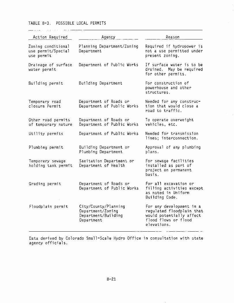
TABLE 8-3. POSSIBLE LOCAL PERMITS
Action Required
Zoning conditional use permit/Special use permit
Drainage of surface water permit
Building permit
Temporary road closure Permit
Other road permits of temporary nature
Ut il i ty permi ts
Plumbing permit
Temporary sewage holding tank permit
Grading permit
Floodplain permit
Agency
Planning Department/Zoning Department
Department of Public Works
Building Department
Department of Roads or Department of Public Works
Department of Roads or Department of Public Works
Department of Public Works
Building Department or Plumbing Department
Sanitation Department or Department of Health
Department of Roads or Department of Public Works
City/County/Planning Department/Zoning Department/Building Department
Reason
Required if hydropower is not a use permitted under present zoning.
If surface water is to be drained. May be required for other permits.
For construction of powerhouse and other structures.
Needed for any construction that would close a road to tra ffi c.
To operate overweight vehicles, etc.
Needed for transmission lines; interconnection.
Approval of any plumbing plans.
For sewage facilities installed as part of project on permanent basis.
For all excavation or filling activities except as noted in Uniform Buil di ng Code.
For any development in a regulated floodplain that would potentially affect flood flows or flood elevations.
Data derived by Colorado Small-Scale Hydro Office in consultation with state agency officials.
8-21

The FERC may permit a IIconduit ll exemption under FERC Order No. 76.
• The FERC may permit a case-by-case exemption under FERC Order
No. 106.
• The FERC may rule that a formal license application is necessary.
You should first review the material in this subsection to determine
which of the above conditions applies. If you are still uncertain as to
which condition applies after reviewing this information, write a letter
requesting an opinion on whether the FERC will assert jurisdiction and
which condition will apply. The letter should give the stream location;
the type of diversion; the design head, flow, and capacity, including, if
available, a flow duration curve for the site; and the land ownership
involved. Contact the FERC at:
Federal Energy Regulatory Commission
Office of Electric Power Regulation
825 North Capitol Street, N.E.
Washington, D.C.
Figure 8-2 is a flow diagram showing possible FERC licensing options
and a list of the FERC regulations that apply. The paragraphs that follow
discuss, in order of increasing effort and time requirement, developer
actions necessary to obtain FERC licensing.
8.3.1.1 No Jurisdiction. The area of no FERC jurisdiction is quite
rare. All of the following conditions would have to apply:
• The development should be in a water conveyance system such as a
pipeline or canal that is privately owned.
• Control of the water should be entirely independent of a free
flowing stream or connected lake system.
8-22

--
co I
N W
2
Options Action Required and Applicable Rules
1-1 FERC rules no jurisdictional responsibility Letter of confirmation' of non FERC responsibility.
Notice of exemption is filed with FERC.Project is a manmade source at an existing ... See Order No. 202; Docket No. RMBI-7; dam. Categorical exemption maybe applied 18 CFR Part 4.for if the site meets the qualifications.
Project is either a manmade or natural source at an existing dam or "natural water feature." Applications for exemption are made on a case-by-case basis.
Application for exemption is required. See ~ Order No. 106; Docket No. RMBO-65;
18 CFR Part 4. 1
Project is on a "conduit." Applicant may - Application for "conduit" exemption required. See FERC Order No.76; Docket No. RM79-35. apply for a "conduit" exemption.
l Project does not qualify for exemption as 5-1 Applicant may apply for a license. ---..
specified above, yet it may still be possible r to obtain a license. Example: Environmental impact of the project is significant.
INEL 2 2684
Figure 8-2. Flow diagram of possible options for FERC licensing.

• The power produced should not be connected to a commercial
transmission system.
If you believe that your development may qualify, write to the FERC
requesting a IIno jurisdiction ll ruling.
8.3.1.2 Notice of Exemption for Existing Dams. If your
microhydropower project involves an existing dam, the simplest action you
can take is to obtain FERC approval through a IInotice of exemption ll from
licensing,a which only takes 30 days from the time of filing with the
FERC. Figure 8-3 is a flow diagram of the application process for the
exemption.
The requirements for approval under this categorical exemption are
quite stringent. To qualify, your proposed microhydropower development
must meet the following conditions:
• The proposed development cannot be larger than 100 kW (it is
assumed throughout this handbook that you are planning a
microhydropower development of 100 kW or less)
• The project must use the water power potential of a manmade
source at an existing dam for generating electrical power.
• Either the existing dam must be at a site where there is no
significant existing population of migratory fish, or it must not
obstruct the passage of fish upstream or downstream.
I The development must not divert water from the waterway for more
than 300 feet from the toe of the dam to the point of discharge
back to the waterway.
a. See FERC Order No. 202, Docket No. RM81-7 dealing with 18 CFR Part 4. This can be found in the Federal Register, Vol. 47, No. 20, January 29, 1982, pp 4232-4246.
8-24
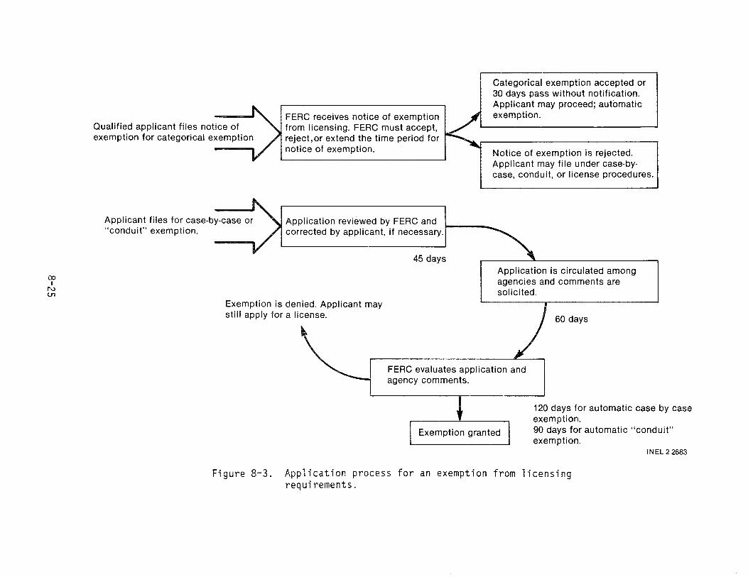
FERC receives notice of exemption Qualified applicant files notice of from licensing. FERC must accept, exemption for categorical exemption reject,or extend the time period for
notice of exemption.
Applicant files for case-by-case or Application reviewed by FERC and "conduit" exemption. corrected by applicant, if necessary.
45 days
co !
N tTl
Exemption is denied. Applicant may still apply for a license.
Categorical exemption accepted or 30 days pass without notification. Applicant may proceed; automatic exemption.
Notice of exemption is rejected. Applicant may file under case-bycase, conduit, or license procedures.
Application is circulated among agencies and comments are solicited.
60 days
FERC evaluates application and agency comments.
120 days for automatic case by case exemption. 90 days for automatic "conduit" exemption.
INEL 2 2683
Figure 8-3. Application process for an exemption from licensing requirements.

• Construction or operation of the development must not adversely
affect any threatened or endangered species or critical habitat
listed in the regulations of the U.S. Fish and Wildlife Service
of Department of the Interior and the National Marine Fisheries
Service of the Department of Commerce.
If only Federal lands are needed to develop and operate the proposed
microhydropower project, any developer may file a notice of exemption from
licensing if the site meets the above criteria. If non-Federal lands are
required to develop and operate the project, the developer must have all
the real property interests in the necessary non-Federal lands in order to
file a notice of exemption.
In filing a notice of exemption with the FERC, you should include
copies of letters from the U.S. Fish and Wildlife Service or a similar
state agency and the state historical agency. The notice of exemption from
licensing is automatically approved if no followup from the FERC is
received within 30 days of the filing.
Although this action completes the licensing procedure with the FERC,
it does not eliminate the need for you to meet all state and local
requirements or to obtain approval to use any Federal lands that may be
involved.
8.3.1.3 Conduit Exemption. If your microhydropower project does
not qualify for the notice of exemption but does use a manmade canal or
conduit, then your next option is to request a conduit exemption. a
The conduit exemption is simpler than a case-by-case exemption (the next
category) because of its location on a manmade conveyance system. If
your site meets the following qualifying criteria, your application for
exemption will be granted within 90 days of filing with the FERC:
a. The conduit exemption is explained in FERC Order No. 76, Docket No. Rm 79-35, which can be found in the Federal Register, Vol 45, No. 83, April 28, 1980, pp 28,085-28,092.
8-26

• The site must be entirely on non-Federal land.
• The principal purpose of the conveyance system must be other than
the generation of electrical power, i.e., water su~ply for
irrigation, domestic use, industrial use, etc.
• No dam can be involved that would not have been built even
without the hydropower generation.
Your application for exemption will be circulated by the FERC to
appropriate Federal agencies for 45 days. If these agencies return no
comments within that period, their acceptance of the application is
assumed. The FERC then has another 45 days to act on the application.
If the FERC takes no action within 90 days of the initial filing, the
application for exemption from licensing under Part I of the Federal Power
Act is automatically granted. If all necessary local and state
requirements have been met, you can now proceed.
8.3.1.4 Case-by-Case Exemption. If your microhydropower project
does not qualify for the notice of exemption and is not using a man-made
canal or conduit, then your next option is to request a case-by-case
exemption. a The case-by-case exemption process is similar to that for
conduit exemptions, but it is broader in coverage and takes 120 days for
automatic approval. The case-by-case exemption covers eXisting dams and
natural water features--that is, elevation features in streams that lend
themselves to diversions for water power generation without the need for a
dam or impoundment--on all lands.
For this case, if your project uses an existing dam, it must have been
built prior to April 20, 1977; furthermore, the impoundment cannot be
altered through reconstruction of an unsafe dam. The operation of the
project must be acceptable to the U.S. Fish and Wildlife Service, or the
a. The case-by-case exemption is explained in FERC order No. 106, Docket No. RM80-65, which can be found in the Federal Register, Vol 45, No. 224, November 18, 1980, pp 76,115-76,165.
8-27

National Marine Fisheries Service, or a similar st6te agency wh~re
appropriate.
If the project site is totally on Federal land, any developer may
apply for an exemption. If non-Federal land is involved, the developer
must have all the necessary non-Federal real property interests on order to
apply.
As mentioned above, your exemption is automatically granted in
120 days if the FERC has not acted. Once again, this does not exempt you
from applicable local, state, and Federal regulations not covered by Part I
of the Federal Power Act. However, obtaining this exemption is a major
step, and it often satisfies other requirements.
8.3.1.5 License. If your microhydropower project cannot be exempted
under one of the above options, then your remaining course is to pursue a
license, generally a minor license. Normally, this procedure will be too
expensive for Category 1 developers to justify. If this route must be
followed, it would be wise for a Category 2 developer to build a project
large enough to cover the costs involved in the rather lengthy licensing
process. Also, you will probably require the assistance of an
architectural engineering firm with experience in hydropower to complete
the licensing process.
There are three actions normally taken by the FERC:
• Issuing an exemption from licensing (already discussed in the
previous paragraphs)
• Issuing a preliminary permit for a hydropower development
Renewing or issuing a license for a hydropower development.
The purpose of obtaining a preliminary permit is to secure priority
for your license where there is competition for development of a site.
This protects your claim to the site while you collect the necessary data
8-28

and make feasibility studies in preparation for submitting the formal
license application. You do not have to have a preliminary permit, but
obtaining one may be a very important step in protecting your claim to a
particular site. Figure 8-4 is a flow chart of the FERC preliminary permit
process. The contents of an application for a preliminary permit are
specified in Section 4.81 of Chapter 1, Federal Energy Regulatory
Commission, Title 18, Conservation of Power and Water Resources, Code of
Federal Regulations (CFR).
The license application is the final and most complex step in the FERC
licensing process. If you cannot obtain an exemption from licensing as
described above, you should be able to use the FERC's short-form license
application for your microhydropower development. The short-form license
applies to minor projects. The requirements for the short-form license
application are specified in Section 4.60 of Chapter 1, CFR 18.
FERC licensing regulations give municipalities and quasi-government
agencies a preference under competitive licensing action. You should
consider the advantage or disadvantage of this preference to a developer
when applying for a license. Under the new rule-making orders of the FERC,
however, this advantage for municipalities and quasi-governmental
developers ceases to exist when exemptions are applied for. Thus, as an
individual microhydropower developer, you are better off securing an
exemption of one form or other rather than going through the complex
licensing process.
8.3.2 Corps of Engineers and EPA Permits
The U.S. Army Corps of Engineers (CDE) through three important Federal
Acts--Section 10 of the Rivers and Harbor of 1899; Section 404 of
P.L. 92-500, the Federal Water Pollution Control Act; and Section 103 of
P.L. 92-532--has responsibility for permits authorizing structures and
materials movement in navigable streams of the United States. This is
often referred to as the navigation servitude requirement through which the
Corps of Engineers protects the navigability of the waters of the nation.
This authority covers the placement of fill necessary for the construction
8-29

Applicant files Declaration of Intent I ~ I Declaration of Intent reviewed by I ~ I If license or exemption is necessary,
+ with FERC 1"1""1 FERC ~ applicant may submit Order No. 54
"Application for Preliminary Permit" to FERC to hold site while completing forms
No license or exemption necessary
1 Preliminary Permit application received and processed
..-----------il FERC invites competing applications for 60-day period
~ Competing application received and processed
co I
W C) Legal and technical analyses may
be required
Application evaluated. Permit goes to applicant whose plans are best adapted to region; if applications are equally well adapted, public entities are given preference over private entities'
-t Application Preliminary Permit is issued for up1 denied to 3 years. r
'Recent practice seems to indicate that the permit goes to the earliest applicant because limited information on the best adopted plan is not available.
INEL 2 2682
Figure 8-4. FERC preliminary permit process.

of any structure; the building of any structure or impoundment requlrlng
rock, sand, dirt, or other materials; the building of dams or dikes; fill
for structures such as intake and outfall pipes associated with power
plants; and any dredging. Figure 8-5 is a flow diagram of the procedure to
be followed in securing a COE permit, known as the 404 permit. Contact the
COE to determine how your project is affected and to obtain copies of the
form (Form 4345) you must use to apply for the 404 permit. COE offices are
listed in Appendix 0-1.
You may have to provide several inputs under' EPA-administered
programs. The most important of these, required under Section 402 of
P.L. 92-500 (33 U.S.C. 1341), is frequently referred to as the 402 permit
or, more specifically, the National Pollution Discharge Elimination System
(NPOES) permit. This section of the act covers the discharge of any
pollutant into a navigable stream from any point source. It requires that
you determine whether your microhydropower development will discharge any
pollutants. If your project in any way diminishes the quality of the water
by adding sediments, decreasing the oxygen content, or increasing the
temperature, it can be considered as discharging pollutants. Another
question is whether a microhydropower development constitutes a point
source. The courts have tended to rule that a dam does constitute a point
source of pollution.
While Federal responsibility for this program lies with the EPA, the
actual administration and field checking are generally delegated to an
appropriate state agency. To apply for a 402 permit or a waiver showing
compliance with the Federal water quality standards, obtain EPA Form 7550-8
from the state agency responsible for assuring compliance with these
standards. This form can also be obtained from the nearest regional office
of the EPA. The state agencies responsible for water quality and pollution
control are listed in Appendix E-4, and EPA offices are listed in Appendix
0-2.
The EPA may also require inputs under Section 404 of P.L. 92-500. The
404 and the 402 permitting processes have many overlapping provisions, and
the question arises: If a 404 permit is granted, does it exempt a
8-31

acknowledged, and processed
Public notice issued
Normal 3D-day comment period
Corps
Individuals
Applicant signs ~__
Application received,
Federal Agencies
Application reviewed by Corps and returns and other interested agencies.
with fee organizations and individuals Permit Issued
Public hearing Application may be held approved
Evaluation Factors
.. Conservation
.. Economics
.. Aesthetics
.. Environmental concerns
.. Fish and wildlife values
.. Flood damage prevention
.. Welfare of the general public
.. Historic values
.. Recreation
.. Land use
.. Water supply
.. Water quality
.. Navigation
.. Energy needs
.. Safety
.. Food production
Application denied ...
INEL 2 2681
Figure 8-5. Flow diagram of U.S. Army Corps of Engineers permit procedures.
8-32

developer from obtaining a 402 permit? There seems to be confusion in the
courts on this issue. While two referencesa,b appear to support the
contention that obtaining a 404 permit does exempt the developer from
obtaining a 402 permit, it would be prudent to check with the EPA.
8.3.3 Other Federal Laws and Federal Land-Use Permits
Even though the permit processes described above cover the most
frequently needed Federal permits, there are other Federal laws you may
need to consider, depending on specific characteristics of your site. The
most important of these laws are listed in Table 8-4, and a brief
discussion of their significance to microhydropower development is
presented in Appendix C. Also in Appendix C is a discussion of Federal
land-use permits such as for the use of Forest Service land. You should
determine at an early stage whether any of these are applicable and, if so,
take the appropriate steps to obtain any necessary permits, approvals, etc.
TABLE 8-4. LIST OF PERTINENT FEDERAL LAWS
1. National Environment Policy Act (January 1, 1970), 91st Congress (P.L. 91-190) 42 U.S.C. 4321F.
2. Fish and Wildlife Coordination Act (August 12, 1958), 85th Congress (P.L. 85-624) 16 U.S.C. 661-64; 1008
3. Endangered Species Act (December 28, 1973), 93rd Congress (P.L. 93-205) 16 U.S.C. 1531-41F.
4. National Historic Preservation Act (October 15, 1966), 89th Congress (P.L. 89-665) 16 U.S.C. 460a-t
a. W. H. Rogers, Environmental Law, West Publishing Co., 1977, p. 399.
b. Environmental Law Institute, Air and Water Pollution Control Law, 1980, p. 485.
8-33
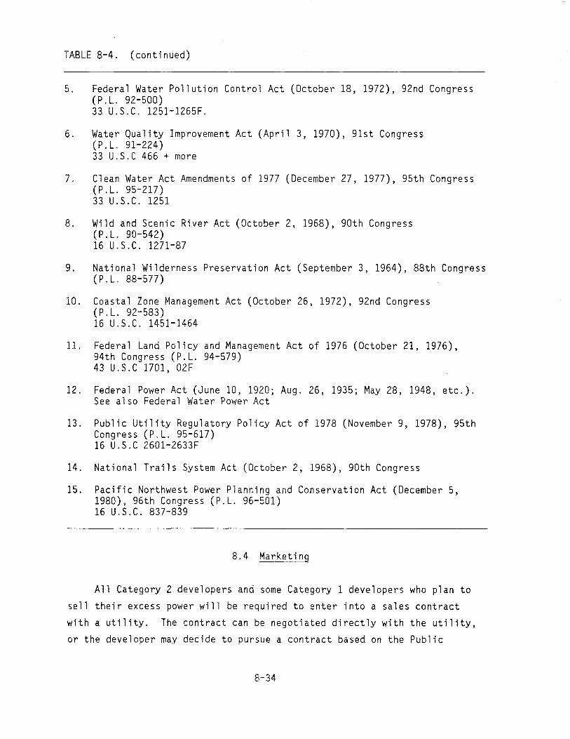
70
TABLE 8-4. (continued)
5. Federal Water Pollution Control Act (October 18, 1972), 92nd Congress (P.L. 92-500) 33 U.S.C. 1251-1265F.
6. Water Quality Improvement Act (April 3, 1970), 91st Congress (P.L. 91-224) 33 U.S.C 466 + more
Clean Water Act Amendments of 1977 (December 27, 1977), 95th Congress (P.L. 95-217) 33 U.S.C. 1251
8. Wild and Scenic River Act (October 2, 1968), 90th Congress (P.L. 90-542) 16 U.S.C. 1271-87
9. National Wilderness Preservation Act (September 3, 1964), 88th Congress (P.L. 88-577)
10. Coastal Zone Management Act (October 26, 1972), 92nd Congress (P.L. 92-583) 16 U.S.C. 1451-1464
11. Federal Land Policy and Management Act of 1976 (October 21, 1976), 94th Congress (P.L. 94-579) 43 U.S.C 1701, 02F
12. Federal Power Act (June 10, 1920; Aug. 26, 1935; May 28, 1948, etc.). See also Federal Water Power Act
13. Public Utility Regulatory Policy Act of 1978 (November 9, 1978), 95th Congress (P.L. 95-617) 16 U.S.C 2601-2633F
14. National Trails System Act (October 2, 1968), 90th Congress
15. Pacific Northwest Power Planning and Conservation Act (December 5, 1980), 96th Congress (P.L. 96-501) 16 U.S.C. 837-839
8.4 Marketing
All Category 2 developers and some Category 1 developers who plan to
sell their excess power will be required to enter into a sales contract
with a utility. The contract can be negotiated directly with the utility,
or the developer may decide to pursue a contract based on the Public
8-34

Utility Regulatory Policy Act (PURPA) rates, which mayor may not be set by
the State PUC. Generally, only Category 2 developers will want to pursue
the PURPA rate and then only if they are producing significant power.
The first part of this subsection discusses a general sales contract.
The second part explains PURPA and what is required to qualify.
8.4.1 Sales Contract
If you are a microhydropower developer who plans to sell power, you
will be required to enter into a written contract for the sale of produced
energy to the power distributing utility. This is a negotiated agreement.
If you are able to finance the project without other securities as
collateral, you will generally need a contract that runs until the
conclusion of debt service payments in order to obtain the necessary
financing. The following are representative contracts:
• One with constant cash flow, in which the purchasing utility pays
a set annual fee independent of the power produced, with an
escalation clause, if desired
• One written to recover all the facility costs plus some profit
for the developer
• One written to require the purchasing utility to pay a floating
price based on its cost of purchasing power elsewhere.
In general, the first case will be less risky for the developer and thus
will usually involve a lower price for the electricity produced. The
second case puts more risk on the developer since it does not cover the
risk of zero output. The third case gives the developer the least
protection but would likely result in a higher unit price for the
electricity sold. Variations of these forms of contracts will prevail,
depending on the desires of the contracting parties. It is customary for
these sales contracts to be on file with the State PUC because the
information is necessary for the commission to set utility rates.
8-35

Normally, you will be required to pay for all costs of interconnection
with the purchasing utility's system. You will also be expected to
purchase insurance covering liabilities arising from the operation of your
microhydropower development and its interconnection with the purchasing
utility's system. The contract will normally specify the phase, current
frequency, voltage, and delivery location of the delivered energy, and will
require appropriate facilities for its connection to the purchasing
utility's system. The terms of the agreement will also define the sales
price or prices, termination procedures, and provisions for reasonable
inspection and for interruption of the electricity. Many purchasing
utilities have developed a standard agreement form for units in the
microhydropower range of 100 kW or less.
You should contact the individual purchasing utility or utilities
early in the planning process to obtain needed information and to develop
the necessary harmonious working relations. Where more than one purchasing
utility is available, there may be a significant difference in the avoided
cost permitted by the PUC. Hence, you should inquire with more than one
utility if possible. You should also contact the State PUC for information
on the various options that are available in the negotiation of the sales
contract.
8.4.2 PURPA
The U.S. Congress in 1978 enacted the Public Utility Regulatory Policy
Act (PURPA), P.L. 95-617 (16 U.S.C. 2701), to help preserve nonrenewable
energy resources and to give incentives for development of renewable
resources that are not being used to their optimum potential. This
includes existing dams and remaining stream sites that are readily
adaptable to power generation but are presently undeveloped. The
construction of small-scale hydropower plants at such stream sites could
lessen the nation's dependence on foreign oil and help alleviate inflation
by countering the Country1s balance of payment deficits. The full text of
PURPA can be found in the Federal Register, Volume 45, No. 56, dated
March 20, 1980.
8-36

Provisions of the act encourage municipalities, electric cooperatives,
industrial development agencies, private entities, and nonprofit
organizations to undertake small-scale hydropower developments at qualified
sites. This is done by requiring electrical utilities to purchase the
power produced by these small power plants at the utility's avoided cost
(see Subsection 8.4.2.2). The act eliminated several problems for
developers: (a) the reluctance of electric utilities to purchase the power
produced because of the lack of in-house control and the perceived
unreliability of the production, (b) the charging of discriminatory rates
for backup power by some electrical utilities, and (c) being considered an
electric utility and thus becoming subject to extensive state and Federal
regulations.
8.4.2.1 Qualifying Facility. Significant among PURPA requirements
is the definition of a IIqualifying facility." Your facility can qualify
for avoided-cost payments from electrical utilities under PURPA as
specified above under the following conditions:
• The power development and all other facilities at the same site
that use the same energy source must not exceed a generating
capacity of 80 MW. Facilities are considered as located at the
same site if they are within one mile of each other and, for
hydropower facilities, if they use water from the same
impoundment for power generation.
• More than 50% of the facility's total energy input must come from
the use of biomass, waste, renewable resources, or a combination
of these.
• The small hydropower facility may not be owned by a person or
company primarily engaged in the generation or sale of electric
power. A cogeneration or small production facility will be
considered as owned by a person or company primarily engaged in
the generation of electric power if more than 50% of the equity
interest in the facility is held by an electric utility or
utilities, or by a public utility holding company or companies or
any combination thereof.
8-37

8.4.2.2 Avoided Cost. The provisions of PURPA, P.L. 95-617, are
designed to provide incentives for developing renewable energy resources,
including hydropower. A number of states have also passed state public
utility regulatory acts to further encourage development of renewable
resources, including hydropower. If the purchasing utility can reduce its
costs or avoid purchasing energy from another utility by purchasing
electric energy from a qualifying facility (as defined above), the rate for
the purchase is to be based on those energy costs that the utility can
avoid, which are called the avoided costs. This implies that the
purchasing facility can defer or delay the construction of a new generating
plant, or decrease the purchase of power from another utility because of
the power purchased from the small hydropower development.
Factors influencing the price you will receive for power you sell
under PURPA include:
a• The availability of capacity or energy at a qualifying
facility during daily and seasonal peak energy demand periods
• The reliability of the capacity or energy supply
• The duration of the period during which the qualifying facility
can contractually guarantee a given capacity or supply of energy
to the utility
• Coordination between the scheduled outages of the qualifying
facility and of the utility
• The backup capability of the qualifying facility in the event of
a utility system emergency
• The lead time associated with the addition of the qualifying
facility
a. The difference between the energy and capacity of a hydropower plant is important in understanding the avoided-cost rate. These terms are defined in the Glossary (Appendix G).
8-38

• Costs or savings that can result from differential line losses in
transmitting and delivering the energy
• Alternative nonrenewable energy fuel costs.
PURPA also requires that the purchasing utility offer to purchase the total
output of energy or capacity or any portion of either that the qualifying
facility wishes to offer. The avoided-cost rate that must be paid to a
qualifying facility
• Shall be just and reasonable and in the public interest
• Shall not discriminate against the qualifying power producer.
The ultimate responsibility for defining the avoided cost has been
assigned to the State PUC or its equivalent in each state. The pues in
turn have required the purchasing utilities to present their supporting
information for defining the avoided costs. The burden of proof falls on
the purchasing utility when it establishes an avoided-cost rate for the
purchase of power. The rate must be based on accurate data and systematic
costing principles.
You must contact both the purchasing utility and the State PUC when
making arrangements for an avoided-cost sale contract under PURPA. State
PUCs are listed in Appendix E-2. Knowing how to contract with a purchasing
utility is important to the early planning of any microhydropower project
from which you plan to sell power. A detailed treatment of this topic for
the state of Washington is covered in Marketing Manual, Volume II,
Developing Hydropower in Washington State, published by the Washington
State Energy Office and the Department of Energy.
8.4.2.3 Sales Opportunity. The PURPA act specifies that purchasing
utilities must purchase the output from qualifying facilities. To take
advantage of this sales opportunity, you must first know that your proposed
microhydropower development is a qualifying facility, as discussed in
Subsection 8.4.2.1, above. Purchasing utilities can include investor-owned
8-39

utilities, municipal electrical utilities, electric cooperatives, public
utility districts, state agencies, federal agencies, or any person who
sells electricity. Federal electric energy marketing entities like the
Tennessee Valley Authority and the Bonneville Power Administration can also
be purchasing utilities. Federal power marketing entities are listed in
Appendix 0-7.
A purchasing utility cannot have more than a 50% equity interest in a
microhydropower development if the development is to be classified as a
qualifying facility and claim the avoided cost price structure mandated by
PURPA. This means that no public utility holding company or person owning
a portion of the purchasing utility can claim the avoided-cost provisions
of PURPA if they also have an equity interest greater than 50% in the
qualifying facility.
The state can furnish listings of purchasing utilities. This
information is normally available from the State PUC (listed in Appendix
E-2) or from the Office of Energy (listed in Appendix E-8) in each state.
Section 292.303 (f) of PURPA indicates that there are situations in
which a purchasing utility is not obligated to purchase energy from the
qualifying facility of a microhydropower developer:
• A purchasing utility is not obligated to purchase from a
qualifying facility during periods when such purchases would
result in a net increase in operating expenses for the electric
utility
A purchasing utility can discontinue purchase from a qualifying
facility during an emergency if the purchase of energy will
contribute to the emergency.
The State PUC or energy regulatory agency has the authority to verify
whether these exemptions from purchase can be allowed. As mentioned
earlier, State pues or the equivalent agencies are listed in Appendix E-2.
8-40

8.5 Example Sites
This section presents step-by-step procedures for obtaining the
necessary certifications, permits, and licenses or exemptions for the two
example sites used in this handbook:
A run-of-the-stream site in Washington State
A manmade site in New Hampshire.
8.5.1 Run-of-the-Stream Site
The run-of-the-stream site is located in mountainous terrain in
Washington. This site has been described previously in Subsection 2.7.
The owner is a Catergory 1 developer whose primary objective is to provide
power for two family dwellings that are currently satisfactorily supplied
power from a 12-kW diesel generator.
For this example, it is assumed that title to the generating site
belongs to the developer. It is also assumed that during the
reconnaissance study, the developer contacted
The Federal Energy Regulatory Commission (the Federal agency
responsible for licensing essentially all non-Federal hydropower
projects)
The Washington Department of Ecology (WDOE) (an environmental
checklist was obtained, filled out, and returned)
The Washington Department of Fish
The Washington Office of Archeological and Historical Preservation
The Washington State Energy Office (WSEO), and
The U.S. Forest Service.
8-41

to determine whether there are any major hindrances to development. Major
hindrances to development would include the presence of a threatened or
endangered species in the site area, an anadromous fish run in the stream,
a historic site at the diversion dam or power plant site, a scenic
designation for the site, or major agency opposition for some reason. Each
agency contacted was asked for advice, the prerequisites for its permit(s),
and the time involved between application and issuance.
Figure 8-6 shows a flow diagram of the licensing process for
microhydropower projects in Washington. The State of Washington has
published an excellent guide book for the licensing process, Developing
Hydropower in Washington State: A Guide to Permits, Licenses, and
Incentives, which can be obtained from either the WDOE or the WSEO. The
developer in Washington should obtain this guide book early in the
reconnaissance process and follow it throughout.
As soon as the reconnaissance study indicates an environmentally and
economically favorable site, the developer should submit to the FERC a
notice of intent to file for an exemption or preliminary permit. Although
a notice of intent is not necessary, it is generally a good investment,
since it secures the site against all competition that might be considering
the same site. A notice of intent to file for exemption only requires an
acknowledgment, whereas it generally takes about 6 months to obtain a
preliminary permit from the FERC. The applicant should specifically ask
for any recent additions or changes in the application process. A number
of ways to simplify the process for small-scale hydropower developments,
especially microhydropower, are currently under study by the FERC.
Every hydropower project must have a water right. Filing for a water
right permit should be one of the developer1s first steps, in order to
establish his claim. Since the WDOE issues Washington water right permits,
there should be no technical problems in obtaining the permit if the
developer has already established contact with the WDOE as previously
suggested.
8-42

Initiating Contacts made with:
1. Federal Energy Regulatory Commission 2. Washington Department of Ecology 3. Washington Department of Fish 4. Washington office of Archeological and Historical Preservation 5. Washington Energy Office
Step 1
Send FERC a notice of intent to apply for a case-by-case exemption, or apply for a preliminary permit, to secure the site while completing the "licensing" process.
Step 2
Local Government Permission
Step 3
Application for Water Right and State Environmental Certification
Step 4
Water Quality Certification
Step 5
U.S. Forest Service Land-Use Permit
Step 6
Miscellaneous Permits as Required
Step 7
Federal Energy Regulatory Commission Case-by-Case Exemption or Minor License
INEL 2 2680
Figure 8-6. Flow diagram of licensing process for a microhydropower project in the state of Washington.
Insofar as possible, the developer should accomplish the steps
described in the following paragraphs simultaneously.
8--43

The microhydropower project must comply with local planning and zoning
ordinances. In this case, the agency for the developer to work with is
probably the county planning and zoning commission or the public works
department. The developer may have to obtain a building permit or a letter
certifying that the proposed project is in compliance with local
ordinances. The building process itself should be discussed with these
local officials since a variety of specialty permits may be needed,
depending on the actual construction process. Page 13 of the Washington
guide book, reproduced here as Table 8-5, lists local permits commonly
required in the State of Washington.
The project will also need environmental certification under SEPA, the
Washington State Environmental Policy Act. The WDOE is the administrator
of this program. This step should be straightforward if the environmental
checklist was filled out and turned in to the WDOE during the
reconnaissance study. The expected result at this point is a negative
declaration, meaning that no significant environmental impact is expected
as a result of the project. This expectation is based on the incorporation
of suggestions received during initial contact with the agency about
minimizing the potential environmental impact of the project. Had a major
obstacle arisen during the initial contacts, it would probably have
required an environmental impact statement, or at least a hearing, either
of which would seriously jeopardize the economics of a microhydropower
project.
If the environmental certification does not include historical and
archeological considerations, then the developer should contact the
appropriate agency and obtain a letter certifying that the site is in
compliance with the related state code. In the State of Washington, this
is the Office of Archeology and Historic Preservation. FERC Order No. 202
does not require a historical and archeological certification on
categorical exemptions for microhydropower projects, but the other
exemption and licensing options do.
Water quality certification is also required under Federal law
(Federal Water Pollution Control Act, P.L. 92-500; Water Quality
8-44

TABLE 8-5. LOCAL PERMITS THAT MIGHT BE NECESSARY IN THE STATE OF WASHINGTON.
LOCAL PERMITS
The local (city and county) permits that are neces· in number, type, application, iocation, and cost. The sary for a hydro project will vary from county to county following table shows the most common permits.
Name From Reason Aeefoximate Time
Shoreline substantial development permit
County Planning Department
Required if any part of project is within 200 ft of an applicable shoreline.a
4 months
Zoning condi· tional use permit
County Planning Department
Required if project is not in conformance with zoning for county master plan.
3 months
Surface water drainage plan approval
County Department of Public Works
Drainage plan must be approved before several other permits can be issued.
1 month
Commercial building permit
County Building and Plumbing Department
Applies to construction of powerhouse.
2 weeks
Temporary road closure permit
County Department of Public Works
Needed for any construction that would completely close a road to traffic.
1 week
Utility permits
County Department of Public Works
Needed for transmission lines and utility intertie.
2 weeks
Sewage holding tank variance
County Department of Health
For sewage facilities installed as part of the project on a permanent basis.
2 months
Grading permit County Department of Public Works
For all excavation or filling activities, except as noted in the Uniform Building Code.
1 month
Plumbing permit County Building and Plumbing Department
Must approve plumbing plans. 1 day
Interlocal agreement for construction on county roads
County Department of Public Works
Short·term agreement applies to upgrading and performing maintenance work on county roads used by overweight con· struction equipment
1 month review 3 months agreement
Permit to operate over· weight vehicles on city or
City/County Department of Public Works
Required only where road conditions are sensitive to damage by overweight vehicles.
1 day
county roads
aShorelines on segments of streams upstream from a point where the mean annual flow is 20 cfs or less and shorelines on lakes less than 20 acres in size are not designated as applicable shorelines.
INEL 2 2665
8-45

Improvement Act, P.L. 91-224; and Clean Water Act Amendments of 1977,
P.L. 95-217). The WDOE is the state agency responsible for this
certification. For the described project, there should be no significant
problems, although the developer may have to install the diversion
structure and bury the penstock piping in accordance with agreed
specifications. In this particular example, the developer may have to
obtain the USFS land use permit described below before the water quality
permit can be issued. The key to minimizing problems at this stage lies in
clarifying the priority of applications during the initial contacts with
the various cognizant agencies.
A U.S. Forest Service permit to use government land for the diversion
structure, penstock, and access roads will be necessary. The developer
should obtain the necessary forms during the reconnaissance study so that
they can be filled out as the required information becomes available.
A variety of other permits could be necessary, depending on the final
project plan and on local and state regulations. Insofar as possible,
these should be determined in advance during the reconnaissance study.
(See pp 13, 17, and 18 6f the Washington handbook for other local and state
permits which might be necessary).
Since the FERC is required by Federal law to ensure compliance with
appropriate local, state, and Federal laws before issuing a license or
exemption, The FERC short-form license or exemption is generally the last
permit the developer obtains before starting construction. In the case of
the categorical exemption for microhydropower under FERC Order No. 202,
however, this is not true. The categorical exemption can be granted before
other Federal, state, and local requirements are complied with. In any
case, the developer should obtain the specific forms required at the time
of initial contact during the reconnaissance study. Much of the
information required by the FERC is identical to that required by the
state. Therefore, certifications or permits from the various state
agen(ies are generally acceptable to the FERC and will greatly expedite
obtaining this final license.
8-46

Once again, the importance of establishing early and ongoing
communication with the permitting agencies to assure orderly compliance
with their requirements cannot be emphasized too strongly.
8.5.2 Manmade Site in New Hampshire
The manmade site is located at an existing dam on a small stream in
the rolling hills of New Hampshire. The site includes an old, retired
gristmill. The electric utility's distribution line passes within
300 yards of the mill. This site has been described previously in
Subsection 2.7. The owner is a Category 2 developer whose primary
objective is to supply his own electrical needs and sell any excess power
to the utility.
As with the previous example, it is assumed that the developer has
approached the licensing process systematically by establishing early
contact with key local, state, and federal agencies. These include
• The Federal Energy Regulatory Commission
• The New Hampshire Water Resource Board
• The New Hampshire Water Supply and Pollution Control Commission
The New Hampshire Department of Fish and Game
• The New Hampshire Department of Resources and Economics
• The responsible local government entity.
Figure 8-7 shows a flow diagram of the licensing process for a
microhydropower project in New Hampshire. Also see Figure 8-1, which shows
a detailed flow diagram of the State of New Hampshire requirements for
hydropower projects of all sizes.
8-47

Initial Contact with local, state and Federal agencies
1. FERC 2. N.H. Water Resource Board 3. N.H. Water Supply and Pollution Control Commission 4. N.H. Department of Fish and Game 5. N.H. Responsible local government entity
Step 1 V Submit a letter of intent to file a notice of exemption, or file for preliminary permit with intent to file for exemption
Step 2 ~ Legal title to dam site NOTE: As many as possible of
these steps should be Step 3 performed simultaneously.~
Water right
Step 4
Dam safety +permit
Step 5 ~ Water quality certification
Step 6 ~ Dredge permit
Step 7 ~ Historic site certification
Step 8 ~ Fish and game certification
Step 9 ~ Planning and zoning certification or building permit
Step 10 ~ FERC exemption
INEL 2 2679
Figure 8-7. Flow diagram of licensing process for a microhydropower project in the state of New Hampshire.
8-48

No two water development sites are exactly the same. The exact number
of permits, certificates, and licenses or exemptions required will vary
with the site characteristics and the mix of private lands, public lands,
public waters, and navigable and nonnavigable waters involved. The exact
step-by-step sequence for licensing this New Hampshire site cannot be
specified without additional site-specific information and the output of
interactions with the various local, state, and Federal agencies. The best
procedure is for the developer to establish agency contacts early. ask for
the necessary licensing forms and any written instructions that might be
available, and then systematically complete the paperwork for local, state,
and Federal licensing.
When making the initial agency contacts, the developer should take or
send a land ownership map of the site, a drawing of the proposed project,
and some pictures of the dam, gristmill, pond area, and stream. These will
help the agency personnel in outlining requirements for licensing the
development.
At the state level, the developer must obtain at least a water right
permit, a dam safety permit, and a water quality permit or certification
under Section 401 of P.L. 92-500. The state agency responsible for these
is the New Hampshire Water Resource Board. The Water Resource Board must
also consider effects on scenic and recreational values, fish and wildlife,
downstream flows, and public uses where appropriate. The developer should
secure all applicable forms at the initial contact.
During the initial contact, the developer should also ask the Water
Resources Board about the historical classification of the old gristmill
and dam. If the Water Resources Board cannot immediately answer this
question, the developer should call or visit the Department of Resources
and Economic Development (see Appendix E-9), which is in charge of historic
preservation, to determine whether the proposed development is affected in
any way.
During initial contact with the Fish and Game Department, the
developer should clarify the status of the impacted land area and the
8-49

stream. Since the stream has a considerable flow, it may be important to
anadromous fisheries, or it may be classified as public trust or even as
navigable. Any of these could present additional requirements leading to
time delays and additional costs. The developer should also ask whether
the development might affect any threatened or endangered species in the
vicinity of the dam site. The presence of such species could greatly
complicate the development of the site.
If the project calls for dredging, the developer will need a permit
from the Water Supply and Pollution Control Commission (see Appendix E-4).
The correct form should be obtained during initial contact with the agency
and filled out in a timely fashion.
Next, assuming that the initial inquiries do not uncover any
insurmountable difficulties, the developer should procure a legal
determination of ownership of the affected lands and the riparian right to
the water. Legal ownership of both sides of the stream at the dam site is
critical. The pondage area could be acquired by eminent domain if
necessary, provided the developer has legal title to the dam site.
As soon as the site ownership is determined, the developer should
submit to the FERC a notice of intent to file for an exemption or
preliminary permit. Although a notice of intent is not necessary, it is
generally a good investment, since, with one exception, it reserves the
site against competitive licensing applications. The developer should have
obtained the ncessary forms during the first contact with FERC and should
have gathered the required information during the reconnaissance study.
The next step is a study to ascertain as closely as possible the
technical, economical, environmental, and institutional feasibility of the
project. The larger the project, the more likely it is that a professional
engineer or consulting firm should be handling this step. An engineer will
need to certify the safety of the dam in this particular project.
Since this project is less than 5 MW, it is exempt from New Hampshire
Public Utility Commission regulations, but the PUC avoided-cost rulings
8-50

could be a major input to the economic analysis and overall project
feasibility. Therefore, the developer should seek out the New Hampshire
PUC (see Appendix E-2) to get this information.
If the stream is considered navigable, the developer will have to
obtain a permit under Section 10 of the Rivers and Harbors Act of 1899 from
the COE, which is responsible for protecting navigable streams. If
dredging is involved, a permit under Section 404 of P.L. 92-500 will
probably be required from the COE as well as from the state. Considerable
review is involved in these permits since The U.S. Environmental Protection
Agency, the U.S. Fish and Wildlife Service, and various state agencies all
comment on them.
At the same time the state and Federal permits are being secured, the
developer should be working with local governmental entities to establish
compliance with the necessary planning and zoning regulations and obtain a
building permit. Land ownership certification and a dam safety permit may
be prerequisites for a building permit. The key to minimizing problems at
this stage lies in clarifying the priority of applications during the
initial contacts with the various cognizant agencies.
All of the necessary forms for licensing should be filled out as part
of the feasibility study so that, with a favorable feasibility report,
licensing can be completed shortly thereafter. The time from the initial
contacts to the licensed project may be more than a year. The larger the
project, the longer this process will take.
Since the FERC is required by Federal law to ensure compliance with
appropriate local, state, and Federal laws before issuing a license or
exemption, The FERC short-form license or exemption is generally the last
permit the developer obtains before starting construction. In the case of
the categorical exemption for microhydropower under FERC Order No. 202,
however, this is not true. The categorical exemption can be granted before
other Federal, state, and local requirements are complied with. In any
case, the developer should obtain the specific forms required at the time
of initial contact during the reconnaissance study. Much of the
8-51

information required by the FERC is identical to that required by the
state. Therefore, certifications or permits from the various state
agencies are generally acceptable to the FERC and will greatly expedite
obtaining this final license.
Once again, the importance of establishing early and ongoing
communication with the permitting agencies to assure orderly compliance
with their requirements cannot be emphasized too strongly.
The FERC is currently streamlining its licensing process for
microhydropower projects. The developer shoufd seek the latest rulings
from the FERC during the initial contact so as to comply with the
correct regulations and minimize the paperwork involved. The
Governor1s Council on Energy 2 1/2 Beacon Street Concord, NH 03301 (603) 271-2711
should also be contacted for the latest New Hampshire information on legal
requirements and also other information on incentives, sales contracts,
marketing, and technical information helps.
Finally, when the project is licensed for construction, the developer
must secure annual permits and plan for annual costs. These should also be
considered in the reconnaissance and feasibility study stages because of
how they influence the overall project economics.
8-52

8.6 Bibliography
Alward, R., Eisenbart, S., Volkman, J., and Haumberger, H., Microhydropower Reviewing an Old Concept, National Center for Appropriate Technology, Butte, Montana, 1979.
Colorado Office of Energy Conservation, et al., "Water Over the Dam, A Small' Scale Hydro."
Klingeman, P: C. and Wheeler, G., Microhydropower: Oregon Development Guide, Extension Circular 1096, Oregon State University Extension Service, January, 1982.
McGuigan, D., Harnessing Water Power for Home Energy, Garden Way Publishing Co., Charlotte, Vermont, 1978, 101 pp.
Office of Federal Register, Code of Federal Regulation, Conservation of Power and Water Resources, Title 18, Parts 1-149, Current year, U.S. Government Printing Office, Washington, D. C.
State of Alaska, Division of Energy and Power Development, "Hydroelectric Commercialization Kit," September 1981.
8-53 1: u.s. GOVERNMENT PRINTING OFFICE: 1983-646-069/618
