428 progranning a multiple-orifice hydraulic …
TRANSCRIPT

RD-A159 428 PROGRANNING A MULTIPLE-ORIFICE HYDRAULIC DECELERATOR 11 ±(U) HARRY G ARMSTRONG AEROSPACE MEDICAL RESEARCH LABWRIGHT-PATTERSON AFS OH C 6 TOLER JUN 85
UN LSSIFIED AAMRL -85F/ O 4/2 NL.UL EEEEEEEEEEEI mlEli....
*1.0 16 -W
11162=
11. L.6~I
MICROCOPY RESOLUTtON TEST CHART
NATIONAL "t AU OF STABOAPOS - 1*63 - A
4%
AAMRL-TR-85-049
00 PROGRAMMING A MULTILE-ORIFICE HYDRAULIC DECELERA7TOR
ICARL G. TOLER
Q
JUNE 1985
Approved for public release; distribution unlimited.
CD,
- -J
MDTIC.ELEC
* HARRYG. ARMSTRONGAEROSPACEMEDICAL RESEARCH LABORATORYAEROSPACE MEDICAL DIVISION SEP 3 0 85AIR FORCE SYS EMS COMMANDWRIGHT-A77ERSON AIR FORCE BASE, OHIO 45433
* b; vu Js I4
d*th. owl* ii'au~ shwdm br~4v~be
* ~~ I~~NOM. bOMw xs~~ POW= .ra~mway. ~U dIsappdmsi i~S~s ~s~ my toa
* Peas donotpsqatcevas Ctb ken Ar e'. Mrsps. ldlcl Bsm'.hLabfay:y
Federal (levmadlnt agencies and their,0044tvo*#~~ 00"I)ba'Iduiel6emUCenter should dbet requiets Sw copies of *A*4pt
* This report has been reviewed by the Office of Public Affals (PA) antd is releasable to the National* Technical Information Service (NTIS). At NTIS, it will be available to the gnwal PUbliev including
- foreign nations.
- This technical report has been reviewed and is approved for publication.
FOR THE COMMANDER
HENIN N GIERKE, Dr IngDirectorBiodynamic. and Bioenghwiering Division
* Air Force Aerospace Medital Research Laboratory
UNCLASSIFIEDSECURITY CLASSIFICATION OF THIS PAGE ql psoe
REPORT DOCUMENTATION PAGE"1. REPORT SECURITY CLASSIFICATION 1b. RESTRICTIVE MARKINGS
Unclassified2.SECURITY CLASSIFICATION AUTHORITY 3. OISTRIBUTION/AVAILASILITY OF REPORT
________________________________ Approved for public release; distribution* b ECLASSIFICATION/DOWNGRAOING SCHEDULE unlimited. I
* 4. PERFORMING ORGANIZATION REPORT NUMBER(S) S. MONITORING ORGANIZATION REPORT NUMBERIS)
* AAI4L-TR-85-049 _____________________
Ba NAME OF PERFORMING ORGANIZATION b. OFFICE SYMBOL 7&. NAME OF MONITORING ORGANIZATION
Harry G. Armstrong Aerospace apmb)
Medical Research Laboratory IAAJ4RL/BBP______________________Sc. ADDRESS (City. State mid ZIP Code) -7b. ADDRESS (City. State and ZIP Code)
Wright-Patterson Air Force Base OH 45433-6573
Se. NAME OF FUNDING/SPONSORING .OFFICE SYMBOL 9. PROCUREMENT INSTRUMENT IDENTIFICATION NUMBER* ORGANIZATION BiomrechanidalOfa~N
* Protection Branch rAAMRL/BBP _______________________BeS. ADDRE6SS (City. State mid ZIP Code) 10. SOURCE OF FUNDING NOB. ___________
PROGRAM IPROJECT TASK WORK UNITWright-Patterson Air Force Base OH 45433-6573 ELE ME NT NO. I NO. No. NO.
11. TITLE 1Inelude Security Chlofllaton)Programmi ng A62202F 7231 1 31 01Multinple-Orifice Hydraulic Decelerator (Ul ______________12. PERSONAL AUTHORIS)
Mr. Carl G. Toler13a. TYPE OF REPORT 13b. TIME COVERED TO14. DATE OF REPORT (Yr.. Mo.. Day) 1S. PAGE COUNT
FnlIFROMarT78 _E"5 June 1985 3016. SUPPLEMENTARY NOTATION
17. COSATI CODES IB. SUBJECT TIERMS (Continue on vhhuerve if necessary and identify by block numer#FIELD IGROUP SUB. an.- Biodynamics Hydraulic Decelerator
Impact Test Facility
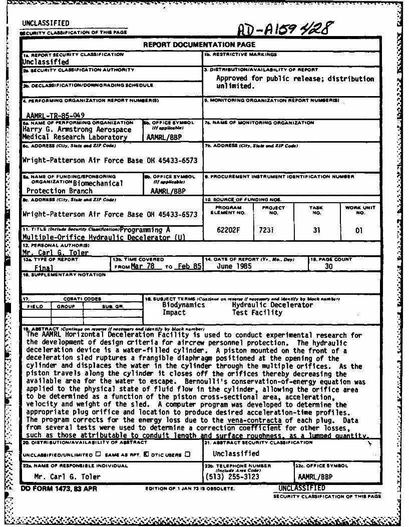
* 19. ABSTRACT (Contginue on revperse if necauory and identify by black number)The AAI'RL Horizontal Deceleration Facility is used to conduct experimental research forthe development of design criteria for aircrew personnel protection. The hydraulicdeceleration device is a water-filled cylinder. A piston mounted on the front of adeceleration sled ruptures a frangible diaphragm positioned at the opening of thecylinder and displaces the water in the cylinder through the multiple orifices. As thepiston travels along the cylinder it closes off the orifices thereby decreasing theavailable area for the water to escape. Bernoulli's conservation-of-energy equation wasapplied to the physical state of fluid flow in the cylinder, allowing the orifice areato be determined as a function of the piston cross-sectional area, acceleration,velocity and weight of the sled. A computer program was developed to determine theappropriate plug orifice and location to produce desired acceleration-time profiles.The program corrects for the energy loss due to the vena-contracta of each plug. Datafrom several tests were used to determine a correction coefficient for other losses,such as those attributable to conduit length .dsraeroughness- as a lumned quantitv-
20. DISTRIBUTION/AVAILABILITY OF ABSTRACT 121. ABSTRACT SECURITY CLASSIFICATION N
UNCLASSIFIEO/UNLIMITEO 0 SAME AS RPT. M OTIC USERS 0 Unclassified22a. NAME OF RESPONSIBLE INDIVIDUAL 122b. TELEPHONE NUMBER 22c. OFFPICE SYMBOL
(Include Anra Code)LMr. Carl G. Toler (51 3) 255-3123 AAI4RL/BBP
~'DO FORM 1473, 83 APR EDITION OF I JAN 73 IS OBSOLETE. (JNCL SFESECURITY CLASSIFICATION OF THIS PAGE
.......................- *.IN
PREFACE
this report was prepared by the Biomechanical Protection Branch,Siodynamics & Bioengineering Division of the Harry G. Armstrong AerospaceMedical Research Laboratory. This report describes a hydraulicdeceleration device, the physical laws governing its operation, andpresents an accurate method of determining the correct orifice arrangementto produce desired acceleration-time profiles.
The author wishes to acknowledge the personnel of the DynalectronCorporation for their support in developing the computer program to producethe desired hydraulic decelerator profile and for the electronic data usedin the analysis. The author is grateful to Capt Michael P. Connors and Mr.James W. Brinkley for their technical assistance and guidance in thisdevelopmental program. Special thanks is offered to Mrs. Jeni Blake forher administrative support in the preparation of this documentation.
Accesion or -
NTlIS CRA&I
DTIC 1A3 a
By. .......
D t b.tiof
A Jlabiiity Codes
*r~v Di~t Avail and/ortDttt Special
I0 r
TABLE OF CONTENTS
Page No.
PREFACE iiiTABLE OF CONTENTS ivLIST OF FIGURES vLIST OF TABLES v
1 INTRODUCTION 1
2 MATERIALS AND METHODS 3
A. Facility 3B. Physical Phenomenon 3C. Solution 8
3 DISCUSSION 13
APPENDIX A 14
REFERENCES 24
* lv
iv
IN9
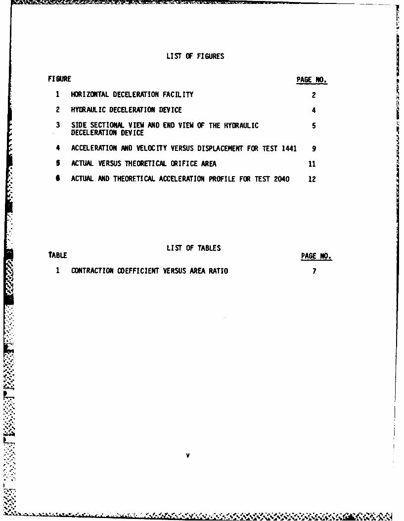
FIGURE LSOFFURSPAGE NO.
I HORIZONTAL DECELERATION FACILITY 2
*2 HYDRAULIC DECELERATION DEVICE 4
3 SIDE SECTIONAL VIEW AND END VIEW OF THE HYDRAULIC 5DECELERATION DEVICE
4 ACCELERATION AND VELOCITY VERSUS DISPLACEMENT FOR TEST 1441 9
5 ACTUAL VERSUS THEORETICAL ORIFICE AREA 11
I ACTUAL AND THEORETICAL ACCELERATION PROFILE FOR TEST 2040 12
LIST OF TABLESTABLE PAGE NO.
I CONTRACTION COEFFICIENT VERSUS AREA RATIO 7

INTRODUCTION
The mission of the Blosuechanical Protection Branch includes development ofdesign criteria for crew protection against transient acceleration andmeasurement of the interaction between the dynamic response of the humanbody and protection systems during acceleration. This technology isacquired for application to the design of crew safety systems such as:emergency escape systems, personnel restraint devices, and impactattenuators. One of the facilities used by the Branch to accomplish thismission is the Horizontal Deceleration Facility.
The Horizontal Deceleration Facility is an impact test facility thatconsists of a launch system, a two-rail track, a sled, and a hydraulicdeceleration device. The facility is shown in Figure 1. The launch systemis used to gradually accelerate the sled along the horizontal track. Thespecimen to be tested is mounted on top of the sled. After separation fromthe launching system, the sled is allowed to free coast along the track for125 feet. During the free-coast phase the sled velocity may be controlledby means of braking devices mounted on the sled. The primary impactenvironment is produced at the end of the free-coast phase by the hydraulicdeceleration device (Kilian and Brown, 1980).
* The hydraulic deceleration device was designed to provide an impact* acceleration-time profile which can be altered to meet the requirements of
different research program. Acceleration-time profiles are produced bythe resisting force on the end of a piston mounted on the front of thesled. During the impact event the piston displaces water through theorifices arranged in a spiral pattern along the cylinder of the hydraulic
* deceleration device. The sizes of the orifices can be changed to controlthe acceleration-time profile. Changing the configuration of the hydraulicdeceleration device for different acceleration profiles has proved to betime consuing and expensive due to the amount of trial and errorassociated with the current method of configuring the device. The samemethod was used to configure the Daisy Decelerator (Chandler, 1967).Several tests are usually required before the desired acceleration-timeprofile is obtained. Therefore, the objective of this study was to developa more accurate and efficient means of establishing correct orificeconfigurations for the hydraulic deceleration device.
.
MATERIALS AND METHODS
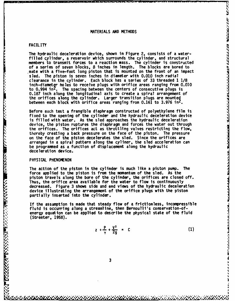
FACILITY
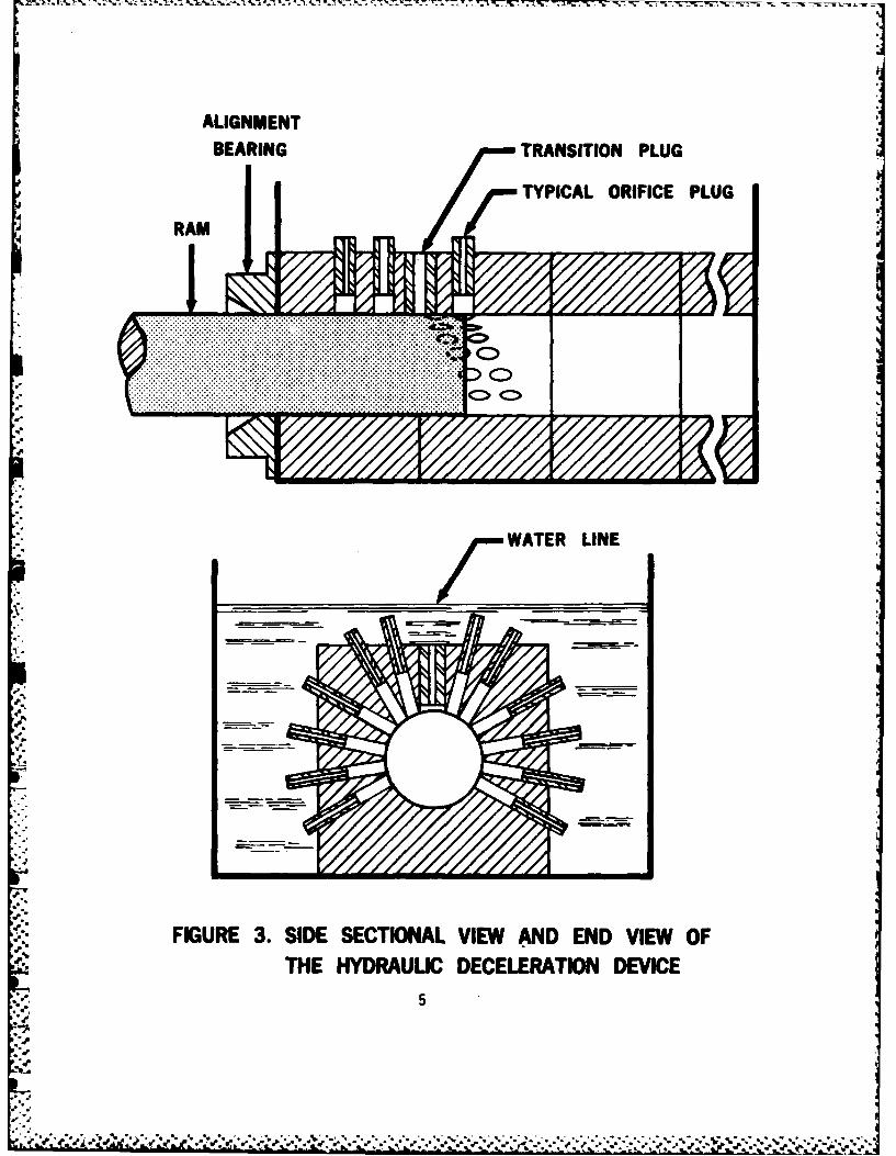
The hydraulic deceleration device, shown in Figure 2, consists of a water-filled cylinder, a reservoir which surrounds the cylinder, and structuralmembers to transmit forces to a reaction mass. The cylinder is constructedof a series of seven blocks, 8 inches in length. The blocks are bored tomate with a five-foot long piston that is mounted on the front of an impactsled. The piston is seven inches in diameter with 0.010 inch radial
clearance in the cylinder. Each block has a series of 33 threaded 1 1/8Iinch-diametlr holes to receive plugs with orifice areas ranging from 0.010to 0.994 in . The spacing between the centers of consecutive plugs is0.187 inch along the longitudinal axis to create a spiral arrangement of tthe orifices along the cylinder. Larger transition plugs are mountedbetween each block with orifice areas ranging from 0.161 to 3.976 in2
Before each test a frangible diaphragm constructed of polyethylene film is* fixed to the opening of the cylinder and the hydraulic deceleration device
is filled with water. As the sled approaches the hydraulic decelerationdevice, the piston ruptures the diaphragm and forces the water out through
* the orifices. The orifices act as throttling valves restricting the flow,* thereby creating a back pressure on the face of the piston. The pressure* on the face of the piston decelerates the sled. Since the orifices are
arranged in a spiral pattern along the cyliner, the sled acceleration canbe programed as a function of displacement along the hydraulicdeceleration device.
PHYSICAL PHENOMENON
The action of the piston in the cylinder is much like a piston pump. Theforce applied to the piston is from the momentum of the sled. As thepiston travels along the bore of the cylinder, the orifices are closed off.Thus, the orifice area available for the water to flow is continuouslydecreased. Figure 3 shows side and end views of the hydraulic decelerationdevice illustrating the arrangement of the orifice plugs with the pistonpartially inserted into the cylinder.
If the assumption is made that steady flow of a frictionless, incompressiblefluid is occurring along a streamline, then Bernoulli's conservation-of-energy equation can be applied to describe the physical state of the fluid(Streeter, 1958).
y 2g
3
ALIGNMENT
BEARINGTRANSITION PLUG
TYPICAL ORIFICE PLUG
T WATER LINE
RA
.. .. .. . . . . .
. . . . .. . . . ... . . . . . .
i': FIGURE 3. SIDE SECTIONAL VIEW AND END VIEW OF
. ThE HYDRAULIC DECELERATION DEVICE
.. .. ..5 .
.....g.......\- . .-. . .........Y e . . C )** S* y - i. . . . .-.. . . . . . . . . . ... .

where A0 is the sum of all the orifice areas not passed by the piston.Substituting equations 3 and 4 in equation 2, the equation of state isdefined as:
WG 2 V A;+ = 2 + HL (5)
ARY 2g 2gA L
In the analysis of fluid flow in a pipeline, several sources are present to
contribute to the energy loss, HL. One source is friction, defined as:
L V2
2Dg (6)
where f is a dimensionless term representing the relative roughness; Le isthe equivalent length of the conduit; and D is the diameter. This losseffect is difficult to determine analytically and is best determinedexperimentally. This is impractical to do for all the orifices. Anothersource is the loss at the entrance to a pipeline from a reservoir. Thisapplies to the entrance of each plug and usually varies between O.05V2/2gto 0.5V 2/2g, depending on the squareness of the edge of the opening. Athird source of energy loss is due to a sudden contraction in a pipeline.This occurs at the base of each plug where the opening is suddenlydecreased from the diameter of the plug to the smaller diameter of theorifice in the plug. The contraction coefficient for water flow in apipeline is known as a function of the area ratio and is presented in Table
Table 1. CONTRACTION COEFFICIENT VERSUS AREA RATIO
A2/A1 - 0.1 0.2 0.3 0.4 0.5 0.6 0.7 0.8 0.9 1.0
Cc - 0.624 .632 .643 .659 .681 .712 .755 .813 .892 1.00
The enc-gy loss due to the contraction is defined as:
V2
(1/C 1)22 (7)
c (C 2g
Substituting hc for HL in equation 5 and rearranging terms, then
Bernoulli's equation becomes:
A0 AR (8)
V(l/Cc - )Z + 1 v'(ZgWsGs/ARVZ + 1
7

A50 //100
VELOCITY ACCELERATION
40o so
*C BOC EE /VL
E 3 0 6 0R */I
II
0 020 5 4 0 NN
I F
- ,,f.
PN S
02
ot:-..::FIGURE 4. ACCELERATION AND VELOCITY VERSUS::- :DISPLACEMENT FOR TEST 1441
.. .r , -['' , ; ' - .. ': . r.,".rL,,. :.-",. ,,"-, ,. -. ,,. .,. .,., .] , - ..- ,,.,-...,',,' ,_,, ,.,-I- --.- . .I-, -
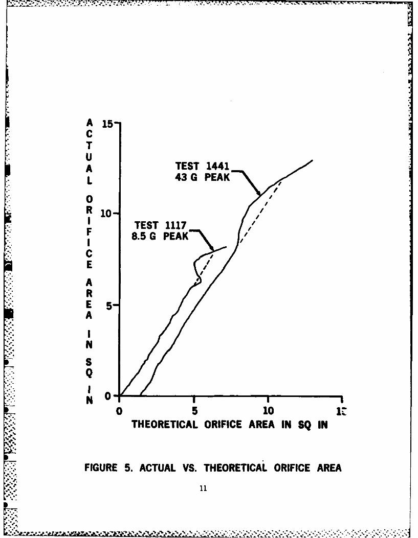
A 15CTUA TEST 1441L 43 G PEAK
0R 1 0I TEST 1117F 8.5 G PEAK./ r
CEARE 5A
IN
S
N 00 5 10
THEORETICAL ORIFICE AREA IN SQ IN
FIGURE 5. ACTUAL VS. THEORETICAL ORIFICE AREA
'-"- 11
p..,:
* a* ,-Y.\\ Kr
DISCUSSION
The hydraulic deceleration orifice profile can be determined by theapplication of Bernoulli's conservation-of-energy equation to the physicalstate of fluid flow during the impact event. Energy losses due to thevena-contracta of each orifice was included in the calculation of therequired orifice area. Losses due to friction and square edged orificeswere determined as a lumped parameter based upon impact test results. Thisprocedure of determining the hydraulic deceleration profile has been used
* for a recent test program and has proven very accurate.
* Several sources of perturbations, not covered in this report, exist whichcan affect the acceleration profiles obtained during impact. One is thepiston striking the alignment bearing prior to entering the hydraulicdeceleration device. This has occasionally produced short-duration pulses
- of various amplitudes at the beginning of the impact profile. The* clearance between the sled glide pads and the rails allows the sled to* vibrate between the rails during impact, which appears as noise on the
acceleration profile. The dynamic interaction between the test subject andseat, especially during low-amplitude long-duration profiles, may alsoalter the pulse shape.
913
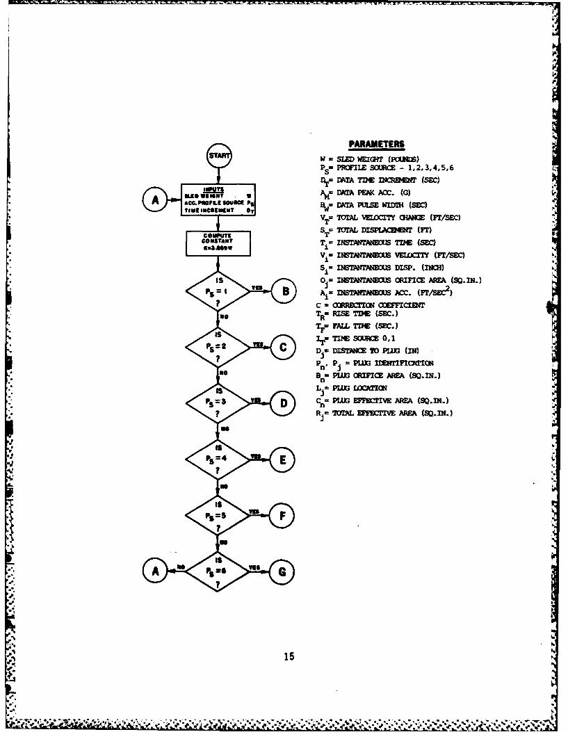
PARAMETERSW =SLED WEIGHT (PcIrs)
PS7POILE SOURCE - 1,2,3,4,5,6
Dlr=DATA7DEINCRE~r(SBC)Lw TAt,=DATA PEACC. (G)
ACC.PAPE SONMUDATA PULSE WIIMl (SEC)
VT = 1TML vmocrry am= (Fr/Sir)
Sp = M1AL DISP1CWW (Fr)Kz3AGOWTi= INTAWNMO T lM (sir)
I V. = INSTARTPNSUS. VELcny (rr/SEc)S INSTANTANOU DISP. (INCH)
Is~ O= INSTANrANixJ.S CfIF7I: AREA (50.111.)YE B A,= nam - P~c. (r.T/s~c)
? C - CRir1'IQ4 OOEFFICIENTTR= RISE TDlE (SEC.)
TF. FALL TIME (SBC.)
YTIME Sow= 0, 1
? c j- DSIANE 70P1W (IN)
Pn, Pj = P~lZ3 MDS~1TFInTINoBe PLUG ORIFICE AREh (30.111.)
PS D %= PLU3 EFFECTIVE ARE (SD.XN.)
? Rj= 7MIAL EFFECTIVE AME (S0.111.)
PS 4
?C
p va
ps =6 va
C,?
* ItMIWSTSI S,
As'
-. 4 Z
44.?
.4.:UT
'4..
A. __________
+ + i-.
.4.-W
T Ir
GPA'W. OOI
17
-. V.
ASSN .~ * Z! z tz
PINISIO 4 1.,
T.--
11
TM umIAufr
296"
* 21

DATA
_p. on ca,OU1 I I 0.944 0.944
2 3 0.681 0.713Po. oce3 31 19.558 OAR0
4 2 0.452 0.4995 32 0.3280.371
IsIs6 4 0.215 0.2407 33 0.159 0.184
%040~~ 6i3 8 0.103 0.120? ? 9 34 0.000 0.093
10 16 0.0S3 0.062U 20O.0W420.04912 25 0.035 0r.041
Is 213 34 Or.027 0.032
15 37 0.08 0.0116 0 0 o
21 44 0.664 0.99422 432 0r.636 0r.73723 433 0.499 0.5W24 46 Or.411 OF.479
&NA-l 26 416 if.212 Or.248igi-. I.S 27 420 0.167 0.196
286425 0.137 0.161
a a

FILMED
10-85
DTIC