3d vision plus - amazon web servicesadjmedia.s3-website-eu-west-1.amazonaws.com/manuals... · adj...
TRANSCRIPT

User Instructions
11/17
3D VISION PLUS
5005510

©2017 ADJ Products, LLC all rights reserved. Information, specifications, diagrams, images, and instructions herein are subject to change without notice. ADJ Products, LLC logo and identifying product names and numbers herein are trademarks of ADJ Products, LLC. Copyright protection claimed includes all forms and matters of copyrightable materials and information now allowed by statutory or judicial law or hereinafter granted. Product names used in this document may be trademarks or registered trademarks of their respective companies and are hereby acknowledged. All non-ADJ Products, LLC brands and product names are trademarks or registered trademarks of their respective companies.ADJ Products, LLC and all affiliated companies hereby disclaim any and all liabilities for property, equipment, building, and electrical damages, injuries to any persons, and direct or indirect economic loss associated with the use or reliance of any information contained within this document, and/or as a result of the improper, unsafe, unsufficient and negligent assembly, installation, rigging, and opera-tion of this product.
Europe Energy Saving NoticeEnergy Saving Matters (EuP 2009/125/EC)Saving electric energy is a key to help protecting the enviroment. Please turn off all electrical products when they are not in use. To avoid power consumption in idle mode, disconnect all electrical equipment from power when not in use. Thank you!
Date DocumentVersion
DMXChannelModes
Notes
DOCUMENT VERSION
Please check www.adj.com for the latest revision/update of this guide.
10/19/17 1 3/9/13 Initial Release
ADJ Products, LLC - www.adj.com - 3D Vision Plus User Manual Page 2
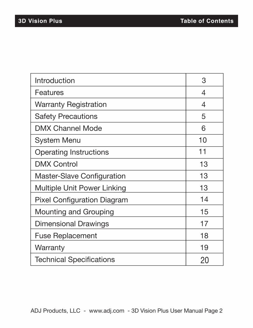
3D Vision Plus Table of Contents
Introduction Features Warranty Registration Safety Precautions DMX Channel Mode System Menu Operating Instructions DMX Control Master-Slave Configuration Multiple Unit Power Linking Pixel Configuration Diagram Mounting and Grouping Dimensional Drawings Fuse Replacement Warranty Technical Specifications
3 4 4 5 6 10 11 13 13 13 14 15 17 18 19 20
ADJ Products, LLC - www.adj.com - 3D Vision Plus User Manual Page 3
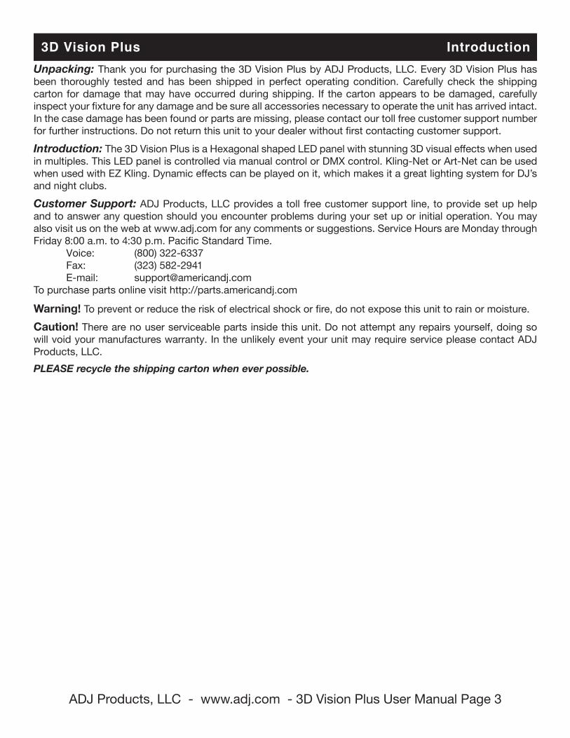
3D Vision Plus IntroductionUnpacking: Thank you for purchasing the 3D Vision Plus by ADJ Products, LLC. Every 3D Vision Plus has been thoroughly tested and has been shipped in perfect operating condition. Carefully check the shipping carton for damage that may have occurred during shipping. If the carton appears to be damaged, carefully inspect your fixture for any damage and be sure all accessories necessary to operate the unit has arrived intact. In the case damage has been found or parts are missing, please contact our toll free customer support number for further instructions. Do not return this unit to your dealer without first contacting customer support. Introduction: The 3D Vision Plus is a Hexagonal shaped LED panel with stunning 3D visual effects when used in multiples. This LED panel is controlled via manual control or DMX control. Kling-Net or Art-Net can be used when used with EZ Kling. Dynamic effects can be played on it, which makes it a great lighting system for DJ’s and night clubs. Customer Support: ADJ Products, LLC provides a toll free customer support line, to provide set up help and to answer any question should you encounter problems during your set up or initial operation. You may also visit us on the web at www.adj.com for any comments or suggestions. Service Hours are Monday through Friday 8:00 a.m. to 4:30 p.m. Pacific Standard Time. Voice: (800) 322-6337 Fax: (323) 582-2941 E-mail: [email protected] purchase parts online visit http://parts.americandj.com
Warning! To prevent or reduce the risk of electrical shock or fire, do not expose this unit to rain or moisture. Caution! There are no user serviceable parts inside this unit. Do not attempt any repairs yourself, doing so will void your manufactures warranty. In the unlikely event your unit may require service please contact ADJ Products, LLC.PLEASE recycle the shipping carton when ever possible.
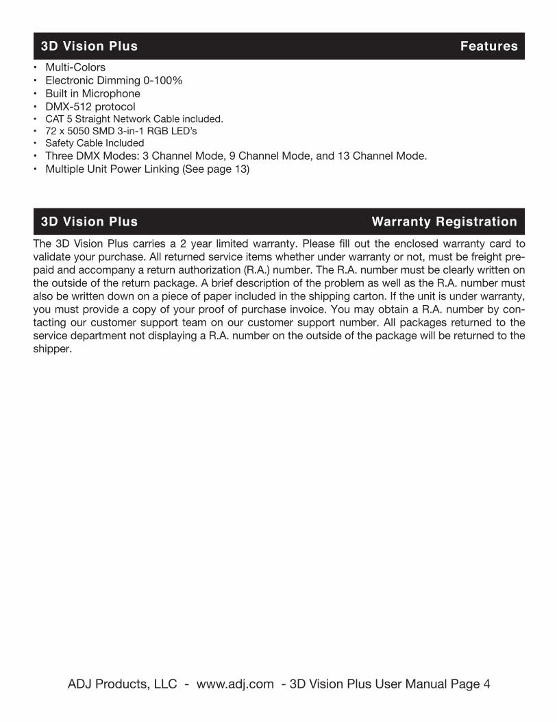
3D Vision Plus Features• Multi-Colors• Electronic Dimming 0-100%• Built in Microphone• DMX-512 protocol• CAT 5 Straight Network Cable included.• 72 x 5050 SMD 3-in-1 RGB LED’s• Safety Cable Included• Three DMX Modes: 3 Channel Mode, 9 Channel Mode, and 13 Channel Mode.• Multiple Unit Power Linking (See page 13)
3D Vision Plus Warranty RegistrationThe 3D Vision Plus carries a 2 year limited warranty. Please fill out the enclosed warranty card to validate your purchase. All returned service items whether under warranty or not, must be freight pre-paid and accompany a return authorization (R.A.) number. The R.A. number must be clearly written on the outside of the return package. A brief description of the problem as well as the R.A. number must also be written down on a piece of paper included in the shipping carton. If the unit is under warranty, you must provide a copy of your proof of purchase invoice. You may obtain a R.A. number by con-tacting our customer support team on our customer support number. All packages returned to the service department not displaying a R.A. number on the outside of the package will be returned to the shipper.
ADJ Products, LLC - www.adj.com - 3D Vision Plus User Manual Page 4
ADJ Products, LLC - www.adj.com - 3D Vision Plus User Manual Page 5
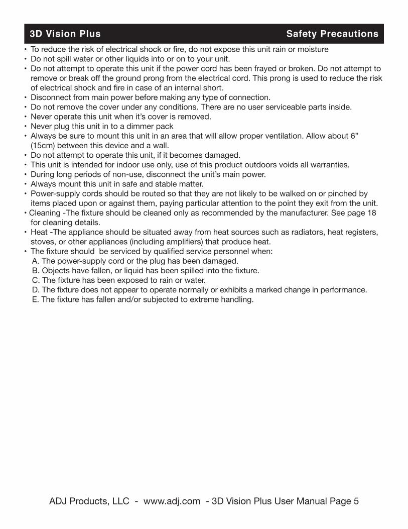
3D Vision Plus Safety Precautions• To reduce the risk of electrical shock or fire, do not expose this unit rain or moisture• Do not spill water or other liquids into or on to your unit.• Do not attempt to operate this unit if the power cord has been frayed or broken. Do not attempt to remove or break off the ground prong from the electrical cord. This prong is used to reduce the risk of electrical shock and fire in case of an internal short.• Disconnect from main power before making any type of connection.• Do not remove the cover under any conditions. There are no user serviceable parts inside.• Never operate this unit when it’s cover is removed.• Never plug this unit in to a dimmer pack• Always be sure to mount this unit in an area that will allow proper ventilation. Allow about 6” (15cm) between this device and a wall.• Do not attempt to operate this unit, if it becomes damaged.• This unit is intended for indoor use only, use of this product outdoors voids all warranties.• During long periods of non-use, disconnect the unit’s main power.• Always mount this unit in safe and stable matter.• Power-supply cords should be routed so that they are not likely to be walked on or pinched by items placed upon or against them, paying particular attention to the point they exit from the unit. • Cleaning -The fixture should be cleaned only as recommended by the manufacturer. See page 18 for cleaning details.• Heat -The appliance should be situated away from heat sources such as radiators, heat registers, stoves, or other appliances (including amplifiers) that produce heat.• The fixture should be serviced by qualified service personnel when: A. The power-supply cord or the plug has been damaged. B. Objects have fallen, or liquid has been spilled into the fixture. C. The fixture has been exposed to rain or water. D. The fixture does not appear to operate normally or exhibits a marked change in performance. E. The fixture has fallen and/or subjected to extreme handling.
ADJ Products, LLC - www.adj.com - 3D Vision Plus User Manual Page 6
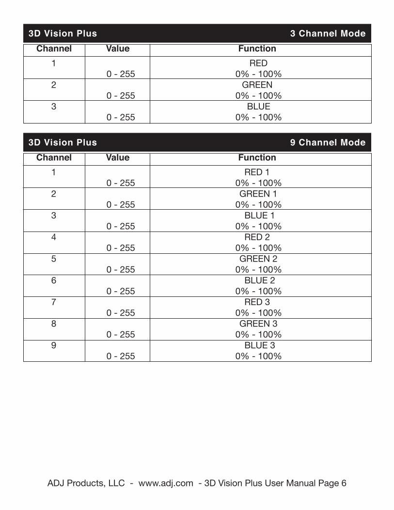
3D Vision Plus 3 Channel Mode Channel Value Function 1 RED 0 - 255 0% - 100% 2 GREEN 0 - 255 0% - 100% 3 BLUE 0 - 255 0% - 100%
3D Vision Plus 9 Channel Mode Channel Value Function 1 RED 1 0 - 255 0% - 100% 2 GREEN 1 0 - 255 0% - 100% 3 BLUE 1 0 - 255 0% - 100% 4 RED 2 0 - 255 0% - 100% 5 GREEN 2 0 - 255 0% - 100% 6 BLUE 2 0 - 255 0% - 100% 7 RED 3 0 - 255 0% - 100% 8 GREEN 3 0 - 255 0% - 100% 9 BLUE 3 0 - 255 0% - 100%
ADJ Products, LLC - www.adj.com - 3D Vision Plus User Manual Page 7
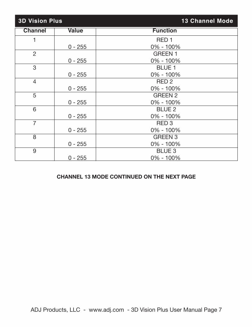
3D Vision Plus 13 Channel Mode Channel Value Function 1 RED 1 0 - 255 0% - 100% 2 GREEN 1 0 - 255 0% - 100% 3 BLUE 1 0 - 255 0% - 100% 4 RED 2 0 - 255 0% - 100% 5 GREEN 2 0 - 255 0% - 100% 6 BLUE 2 0 - 255 0% - 100% 7 RED 3 0 - 255 0% - 100% 8 GREEN 3 0 - 255 0% - 100% 9 BLUE 3 0 - 255 0% - 100%
CHANNEL 13 MODE CONTINUED ON THE NEXT PAGE
ADJ Products, LLC - www.adj.com - 3D Vision Plus User Manual Page 8
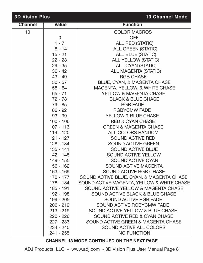
3D Vision Plus 13 Channel Mode Channel Value Function 10 COLOR MACROS 0 OFF 1 - 7 ALL RED (STATIC) 8 - 14 ALL GREEN (STATIC) 15 - 21 ALL BLUE (STATIC) 22 - 28 ALL YELLOW (STATIC) 29 - 35 ALL CYAN (STATIC) 36 - 42 ALL MAGENTA (STATIC) 43 - 49 RGB CHASE 50 - 57 BLUE, CYAN, & MAGENTA CHASE 58 - 64 MAGENTA, YELLOW, & WHITE CHASE 65 - 71 YELLOW & MAGENTA CHASE 72 - 78 BLACK & BLUE CHASE 79 - 85 RGB FADE 86 - 92 RGBYCMW FADE 93 - 99 YELLOW & BLUE CHASE 100 - 106 RED & CYAN CHASE 107 - 113 GREEN & MAGENTA CHASE 114 - 120 ALL COLORS RANDOM 121 - 127 SOUND ACTIVE RED 128 - 134 SOUND ACTIVE GREEN 135 - 141 SOUND ACTIVE BLUE 142 - 148 SOUND ACTIVE YELLOW 149 - 155 SOUND ACTIVE CYAN 156 - 162 SOUND ACTIVE MAGENTA 163 - 169 SOUND ACTIVE RGB CHASE 170 - 177 SOUND ACTIVE BLUE, CYAN, & MAGENTA CHASE 178 - 184 SOUND ACTIVE MAGENTA, YELLOW & WHITE CHASE 185 - 191 SOUND ACTIVE YELLOW & MAGENTA CHASE 192 - 198 SOUND ACTIVE BLACK & BLUE CHASE 199 - 205 SOUND ACTIVE RGB FADE 206 - 212 SOUND ACTIVE RGBYCMW FADE 213 - 219 SOUND ACTIVE YELLOW & BLUE CHASE 220 - 226 SOUND ACTIVE RED & CYAN CHASE 227 - 233 SOUND ACTIVE GREEN & MAGENTA CHASE 234 - 240 SOUND ACTIVE ALL COLORS 241 - 255 NO FUNCTION
CHANNEL 13 MODE CONTINUED ON THE NEXT PAGE
ADJ Products, LLC - www.adj.com - 3D Vision Plus User Manual Page 9
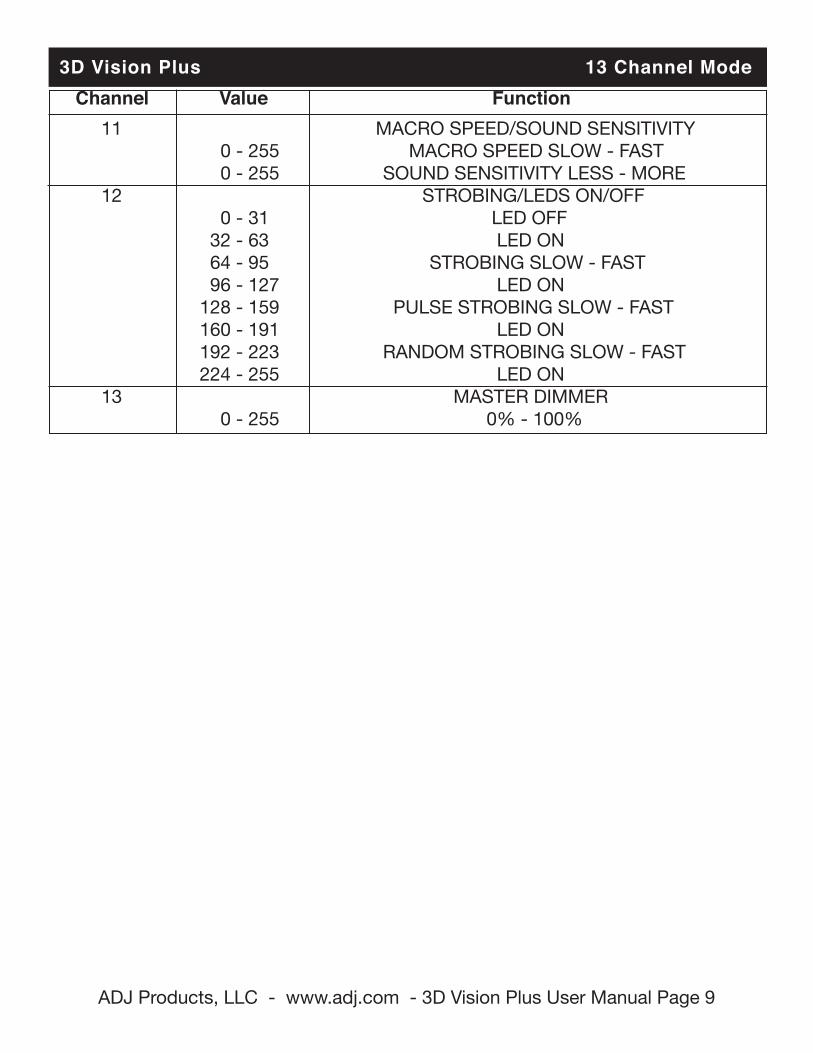
3D Vision Plus 13 Channel Mode Channel Value Function 11 MACRO SPEED/SOUND SENSITIVITY 0 - 255 MACRO SPEED SLOW - FAST 0 - 255 SOUND SENSITIVITY LESS - MORE 12 STROBING/LEDS ON/OFF 0 - 31 LED OFF 32 - 63 LED ON 64 - 95 STROBING SLOW - FAST 96 - 127 LED ON 128 - 159 PULSE STROBING SLOW - FAST 160 - 191 LED ON 192 - 223 RANDOM STROBING SLOW - FAST 224 - 255 LED ON 13 MASTER DIMMER 0 - 255 0% - 100%
ADJ Products, LLC - www.adj.com - 3D Vision Plus User Manual Page 10
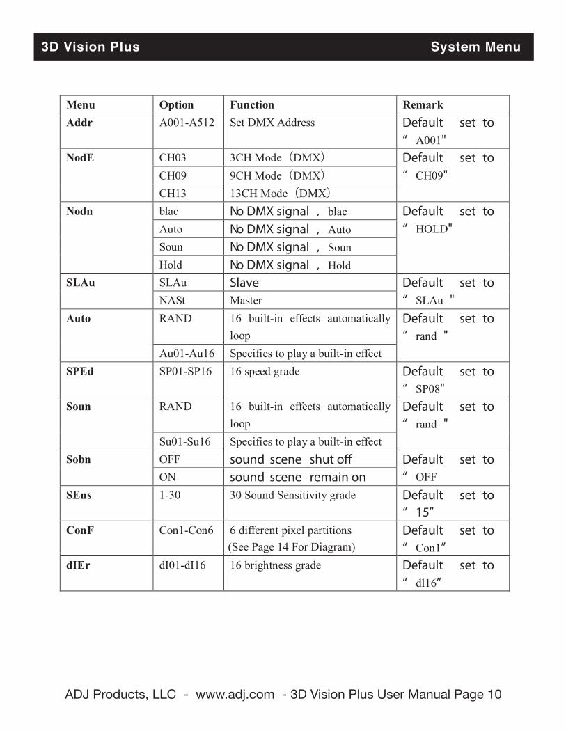
3D Vision Plus System Menu
Menu Option Function Remark Addr A001-A512 Set DMX Address Default set to
“ A001" NodE CH03 3CH Mode(DMX) Default set to
“ CH09" CH09 9CH Mode(DMX) CH13 13CH Mode(DMX)
Nodn
blac No DMX signal ,blac Default set to “ HOLD" Auto No DMX signal ,Auto
Soun No DMX signal ,Soun Hold No DMX signal ,Hold
SLAu SLAu Slave Default set to “ SLAu " NASt Master
Auto RAND 16 built-in effects automatically loop
Default set to “ rand "
Au01-Au16 Specifies to play a built-in effect SPEd SP01-SP16 16 speed grade Default set to
“ SP08" Soun RAND 16 built-in effects automatically
loop Default set to “ rand "
Su01-Su16 Specifies to play a built-in effect Sobn OFF sound scene shut o� Default set to
“ OFF ON sound scene remain on SEns 1-30 30 Sound Sensitivity grade Default set to
“ 15” ConF Con1-Con6 6 different pixel partitions Default set to
“ Con1” dIEr dI01-dI16 16 brightness grade Default set to
“ dl16”
(See Page 14 For Diagram)
ADJ Products, LLC - www.adj.com - 3D Vision Plus User Manual Page 11
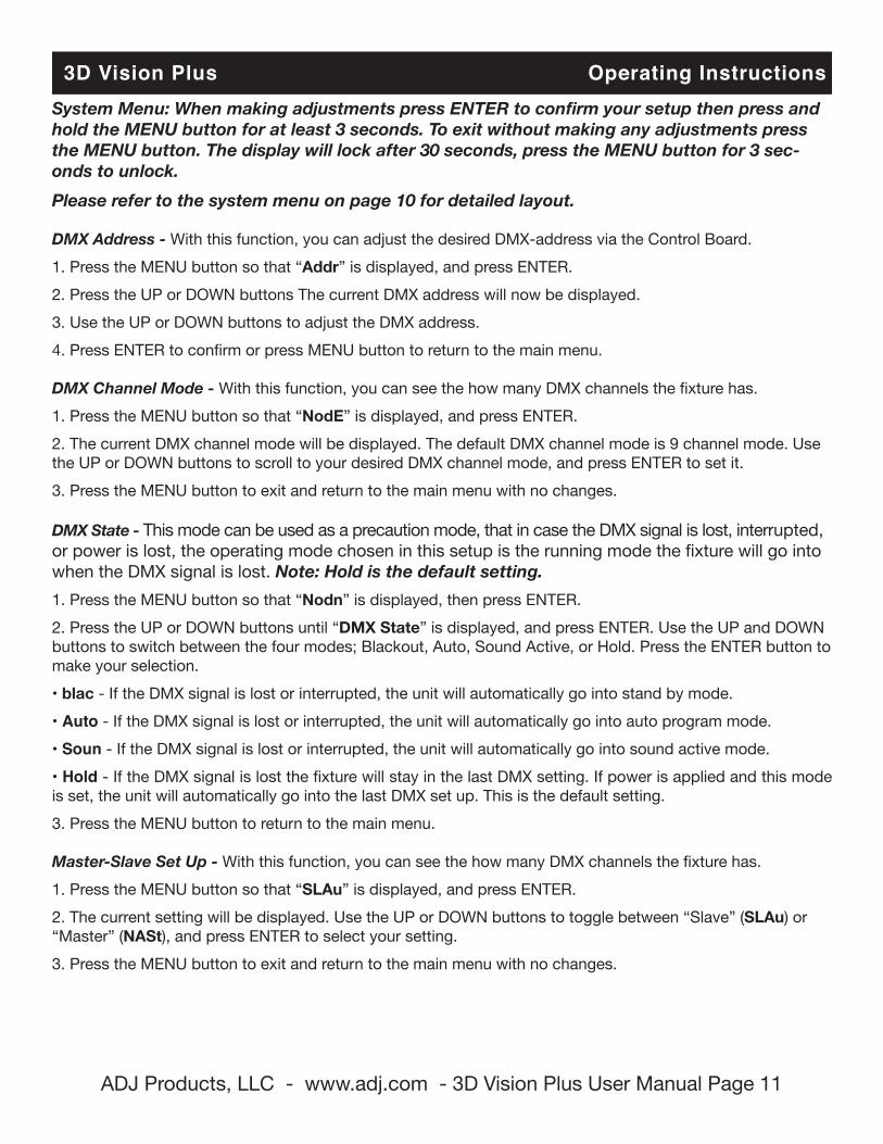
3D Vision Plus Operating InstructionsSystem Menu: When making adjustments press ENTER to confirm your setup then press and hold the MENU button for at least 3 seconds. To exit without making any adjustments press the MENU button. The display will lock after 30 seconds, press the MENU button for 3 sec-onds to unlock.Please refer to the system menu on page 10 for detailed layout.
DMX Address - With this function, you can adjust the desired DMX-address via the Control Board.1. Press the MENU button so that “Addr” is displayed, and press ENTER.2. Press the UP or DOWN buttons The current DMX address will now be displayed.3. Use the UP or DOWN buttons to adjust the DMX address.4. Press ENTER to confirm or press MENU button to return to the main menu.
DMX Channel Mode - With this function, you can see the how many DMX channels the fixture has.1. Press the MENU button so that “NodE” is displayed, and press ENTER.2. The current DMX channel mode will be displayed. The default DMX channel mode is 9 channel mode. Use the UP or DOWN buttons to scroll to your desired DMX channel mode, and press ENTER to set it.3. Press the MENU button to exit and return to the main menu with no changes.
DMX State - This mode can be used as a precaution mode, that in case the DMX signal is lost, interrupted, or power is lost, the operating mode chosen in this setup is the running mode the fixture will go into when the DMX signal is lost. Note: Hold is the default setting.1. Press the MENU button so that “Nodn” is displayed, then press ENTER.2. Press the UP or DOWN buttons until “DMX State” is displayed, and press ENTER. Use the UP and DOWN buttons to switch between the four modes; Blackout, Auto, Sound Active, or Hold. Press the ENTER button to make your selection.• blac - If the DMX signal is lost or interrupted, the unit will automatically go into stand by mode.• Auto - If the DMX signal is lost or interrupted, the unit will automatically go into auto program mode.• Soun - If the DMX signal is lost or interrupted, the unit will automatically go into sound active mode.• Hold - If the DMX signal is lost the fixture will stay in the last DMX setting. If power is applied and this mode is set, the unit will automatically go into the last DMX set up. This is the default setting. 3. Press the MENU button to return to the main menu.
Master-Slave Set Up - With this function, you can see the how many DMX channels the fixture has.1. Press the MENU button so that “SLAu” is displayed, and press ENTER.2. The current setting will be displayed. Use the UP or DOWN buttons to toggle between “Slave” (SLAu) or “Master” (NASt), and press ENTER to select your setting.3. Press the MENU button to exit and return to the main menu with no changes.
ADJ Products, LLC - www.adj.com - 3D Vision Plus User Manual Page 12
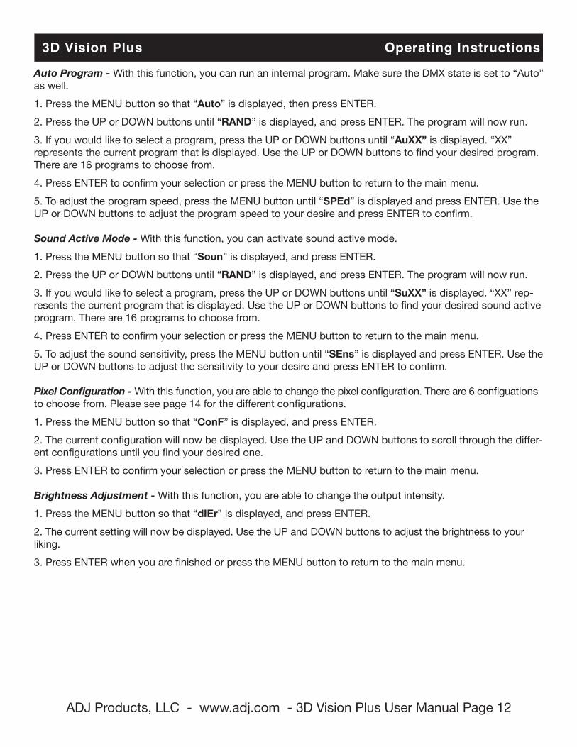
Auto Program - With this function, you can run an internal program. Make sure the DMX state is set to “Auto”as well.1. Press the MENU button so that “Auto” is displayed, then press ENTER.2. Press the UP or DOWN buttons until “RAND” is displayed, and press ENTER. The program will now run.3. If you would like to select a program, press the UP or DOWN buttons until “AuXX” is displayed. “XX” represents the current program that is displayed. Use the UP or DOWN buttons to find your desired program. There are 16 programs to choose from.4. Press ENTER to confirm your selection or press the MENU button to return to the main menu.5. To adjust the program speed, press the MENU button until “SPEd” is displayed and press ENTER. Use the UP or DOWN buttons to adjust the program speed to your desire and press ENTER to confirm.
Sound Active Mode - With this function, you can activate sound active mode.1. Press the MENU button so that “Soun” is displayed, and press ENTER.2. Press the UP or DOWN buttons until “RAND” is displayed, and press ENTER. The program will now run.3. If you would like to select a program, press the UP or DOWN buttons until “SuXX” is displayed. “XX” rep-resents the current program that is displayed. Use the UP or DOWN buttons to find your desired sound active program. There are 16 programs to choose from.4. Press ENTER to confirm your selection or press the MENU button to return to the main menu.5. To adjust the sound sensitivity, press the MENU button until “SEns” is displayed and press ENTER. Use the UP or DOWN buttons to adjust the sensitivity to your desire and press ENTER to confirm.
Pixel Configuration - With this function, you are able to change the pixel configuration. There are 6 configuations to choose from. Please see page 14 for the different configurations.1. Press the MENU button so that “ConF” is displayed, and press ENTER.2. The current configuration will now be displayed. Use the UP and DOWN buttons to scroll through the differ-ent configurations until you find your desired one.3. Press ENTER to confirm your selection or press the MENU button to return to the main menu.
Brightness Adjustment - With this function, you are able to change the output intensity.1. Press the MENU button so that “dIEr” is displayed, and press ENTER.2. The current setting will now be displayed. Use the UP and DOWN buttons to adjust the brightness to your liking.3. Press ENTER when you are finished or press the MENU button to return to the main menu.
3D Vision Plus Operating Instructions
ADJ Products, LLC - www.adj.com - 3D Vision Plus User Manual Page 13
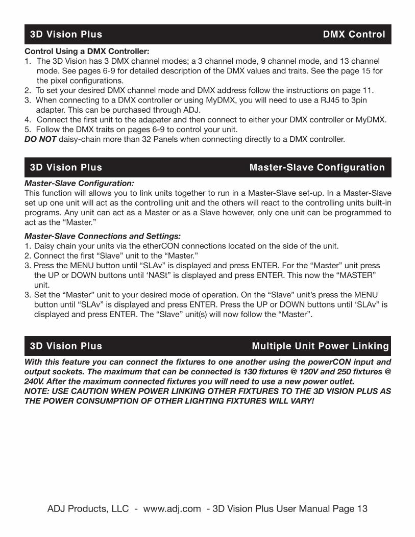
3D Vision Plus DMX ControlControl Using a DMX Controller:1. The 3D Vision has 3 DMX channel modes; a 3 channel mode, 9 channel mode, and 13 channel mode. See pages 6-9 for detailed description of the DMX values and traits. See the page 15 for the pixel configurations.2. To set your desired DMX channel mode and DMX address follow the instructions on page 11.3. When connecting to a DMX controller or using MyDMX, you will need to use a RJ45 to 3pin adapter. This can be purchased through ADJ. 4. Connect the first unit to the adapater and then connect to either your DMX controller or MyDMX.5. Follow the DMX traits on pages 6-9 to control your unit.DO NOT daisy-chain more than 32 Panels when connecting directly to a DMX controller.
Master-Slave Configuration: This function will allows you to link units together to run in a Master-Slave set-up. In a Master-Slave set up one unit will act as the controlling unit and the others will react to the controlling units built-in programs. Any unit can act as a Master or as a Slave however, only one unit can be programmed to act as the “Master.” Master-Slave Connections and Settings:1. Daisy chain your units via the etherCON connections located on the side of the unit. 2. Connect the first “Slave” unit to the “Master.”3. Press the MENU button until “SLAv” is displayed and press ENTER. For the “Master” unit press the UP or DOWN buttons until ‘NASt” is displayed and press ENTER. This now the “MASTER” unit.3. Set the “Master” unit to your desired mode of operation. On the “Slave” unit’s press the MENU button until “SLAv” is displayed and press ENTER. Press the UP or DOWN buttons until ‘SLAv” is displayed and press ENTER. The “Slave” unit(s) will now follow the “Master”.
3D Vision Plus Master-Slave Configuration
3D Vision Plus Multiple Unit Power LinkingWith this feature you can connect the fixtures to one another using the powerCON input and output sockets. The maximum that can be connected is 130 fixtures @ 120V and 250 fixtures @ 240V. After the maximum connected fixtures you will need to use a new power outlet. NOTE: USE CAUTION WHEN POWER LINKING OTHER FIXTURES TO THE 3D VISION PLUS AS THE POWER CONSUMPTION OF OTHER LIGHTING FIXTURES WILL VARY!
ADJ Products, LLC - www.adj.com - 3D Vision Plus User Manual Page 14
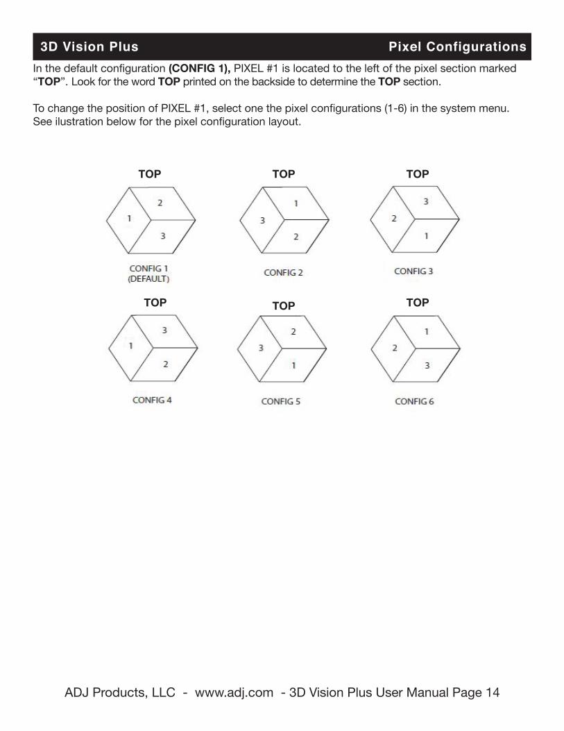
3D Vision Plus Pixel ConfigurationsIn the default configuration (CONFIG 1), PIXEL #1 is located to the left of the pixel section marked “TOP”. Look for the word TOP printed on the backside to determine the TOP section.
To change the position of PIXEL #1, select one the pixel configurations (1-6) in the system menu.See ilustration below for the pixel configuration layout.
TOP TOP TOP
TOP TOP TOP
ADJ Products, LLC - www.adj.com - 3D Vision Plus User Manual Page 15
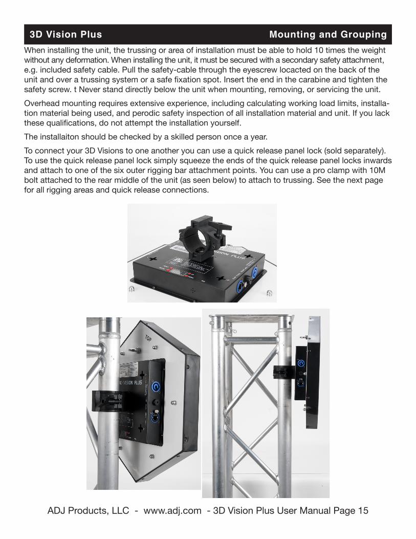
When installing the unit, the trussing or area of installation must be able to hold 10 times the weight without any deformation. When installing the unit, it must be secured with a secondary safety attachment, e.g. included safety cable. Pull the safety-cable through the eyescrew locacted on the back of the unit and over a trussing system or a safe fixation spot. Insert the end in the carabine and tighten the safety screw. t Never stand directly below the unit when mounting, removing, or servicing the unit. Overhead mounting requires extensive experience, including calculating working load limits, installa-tion material being used, and perodic safety inspection of all installation material and unit. If you lack these qualifications, do not attempt the installation yourself.The installaiton should be checked by a skilled person once a year.To connect your 3D Visions to one another you can use a quick release panel lock (sold separately). To use the quick release panel lock simply squeeze the ends of the quick release panel locks inwards and attach to one of the six outer rigging bar attachment points. You can use a pro clamp with 10M bolt attached to the rear middle of the unit (as seen below) to attach to trussing. See the next page for all rigging areas and quick release connections.
3D Vision Plus Mounting and Grouping
ADJ Products, LLC - www.adj.com - 3D Vision Plus User Manual Page 16
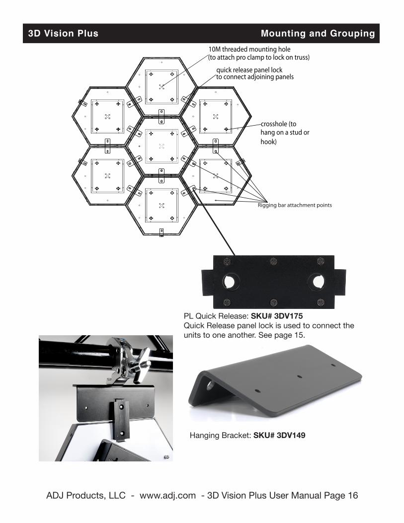
crosshole (to hang on a stud orhook)
10M threaded mounting hole(to attach pro clamp to lock on truss)
quick release panel lock to connect adjoining panels
Rigging bar attachment points
3D Vision Plus Mounting and Grouping
Hanging Bracket: SKU# 3DV149
PL Quick Release: SKU# 3DV175Quick Release panel lock is used to connect the units to one another. See page 15.
ADJ Products, LLC - www.adj.com - 3D Vision Plus User Manual Page 17
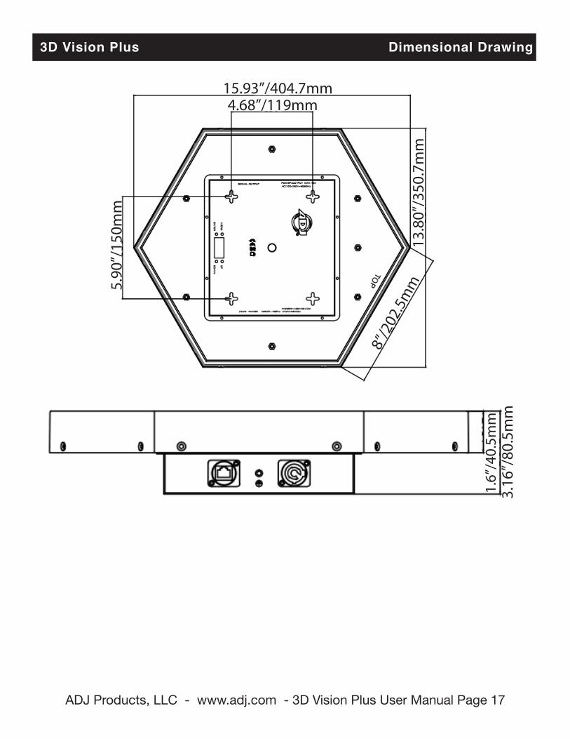
3D Vision Plus Dimensional Drawing
15.93”/404.7mm4.68”/119mm
5.90
”/15
0mm
13.8
0”/3
50.7
mm
8”/2
02.5
mm
3.16
”/80
.5m
m1.
6”/4
0.5m
m
ADJ Products, LLC - www.adj.com - 3D Vision Plus User Manual Page 18
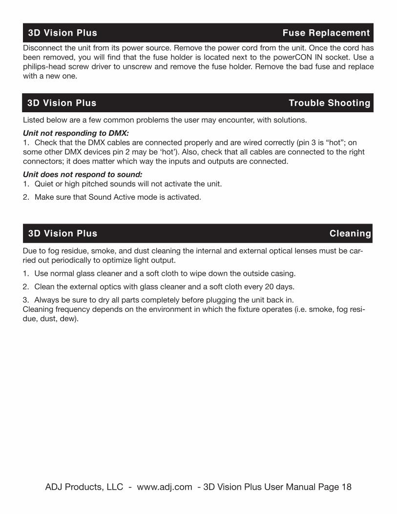
3D Vision Plus Fuse Replacement
3D Vision Plus Trouble Shooting
3D Vision Plus Cleaning
Listed below are a few common problems the user may encounter, with solutions.Unit not responding to DMX:1. Check that the DMX cables are connected properly and are wired correctly (pin 3 is “hot”; on some other DMX devices pin 2 may be ‘hot’). Also, check that all cables are connected to the right connectors; it does matter which way the inputs and outputs are connected.Unit does not respond to sound:1. Quiet or high pitched sounds will not activate the unit.2. Make sure that Sound Active mode is activated.
Due to fog residue, smoke, and dust cleaning the internal and external optical lenses must be car-ried out periodically to optimize light output. 1. Use normal glass cleaner and a soft cloth to wipe down the outside casing.2. Clean the external optics with glass cleaner and a soft cloth every 20 days.3. Always be sure to dry all parts completely before plugging the unit back in.Cleaning frequency depends on the environment in which the fixture operates (i.e. smoke, fog resi-due, dust, dew).
Disconnect the unit from its power source. Remove the power cord from the unit. Once the cord has been removed, you will find that the fuse holder is located next to the powerCON IN socket. Use a philips-head screw driver to unscrew and remove the fuse holder. Remove the bad fuse and replace with a new one.
ADJ Products, LLC - www.adj.com - 3D Vision Plus User Manual Page 19
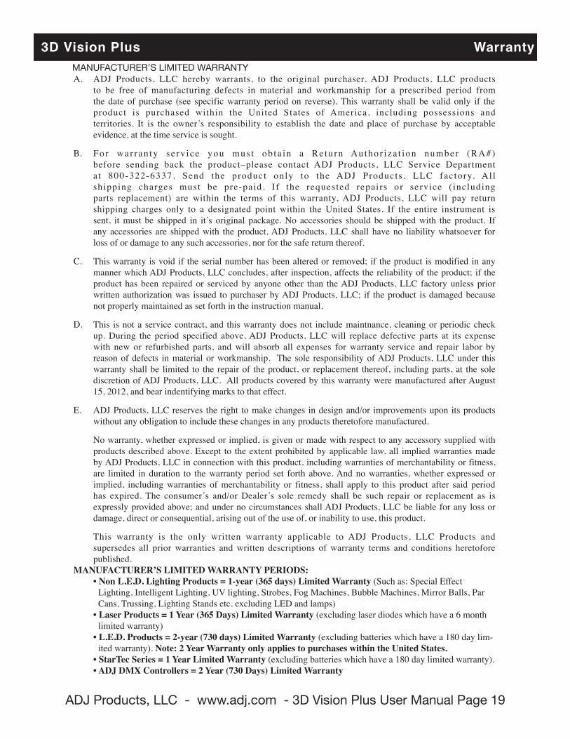
3D Vision Plus WarrantyMANUFACTURER’S LIMITED WARRANTYA. ADJ Products, LLC hereby warrants, to the original purchaser, ADJ Products, LLC products to be free of manufacturing defects in material and workmanship for a prescribed period from the date of purchase (see specific warranty period on reverse). This warranty shall be valid only if the product is purchased within the United States of America, including possessions and territories. It is the owner’s responsibility to establish the date and place of purchase by acceptable evidence, at the time service is sought.
B. Fo r war ran ty s e rv i ce you mus t ob t a in a Re tu rn Au tho r i za t i on number (RA#) before sending back the product–please contact ADJ Products, LLC Service Department a t 800-322-6337. Send the product only to the ADJ Products , LLC factory. Al l shipping charges must be pre-paid. If the requested repairs or service ( including parts replacement) are within the terms of this warranty, ADJ Products, LLC will pay return shipping charges only to a designated point within the United States. If the entire instrument is sent, it must be shipped in it’s original package. No accessories should be shipped with the product. If any accessories are shipped with the product, ADJ Products, LLC shall have no liability whatsoever for loss of or damage to any such accessories, nor for the safe return thereof.
C. This warranty is void if the serial number has been altered or removed; if the product is modified in any manner which ADJ Products, LLC concludes, after inspection, affects the reliability of the product; if the product has been repaired or serviced by anyone other than the ADJ Products, LLC factory unless prior written authorization was issued to purchaser by ADJ Products, LLC; if the product is damaged because not properly maintained as set forth in the instruction manual.
D. This is not a service contract, and this warranty does not include maintnance, cleaning or periodic check up. During the period specified above, ADJ Products, LLC will replace defective parts at its expense with new or refurbished parts, and will absorb all expenses for warranty service and repair labor by reason of defects in material or workmanship. The sole responsibility of ADJ Products, LLC under this warranty shall be limited to the repair of the product, or replacement thereof, including parts, at the sole discretion of ADJ Products, LLC. All products covered by this warranty were manufactured after August 15, 2012, and bear indentifying marks to that effect.
E. ADJ Products, LLC reserves the right to make changes in design and/or improvements upon its products without any obligation to include these changes in any products theretofore manufactured.
No warranty, whether expressed or implied, is given or made with respect to any accessory supplied with products described above. Except to the extent prohibited by applicable law, all implied warranties made by ADJ Products, LLC in connection with this product, including warranties of merchantability or fitness, are limited in duration to the warranty period set forth above. And no warranties, whether expressed or implied, including warranties of merchantability or fitness, shall apply to this product after said period has expired. The consumer’s and/or Dealer’s sole remedy shall be such repair or replacement as is expressly provided above; and under no circumstances shall ADJ Products, LLC be liable for any loss or damage, direct or consequential, arising out of the use of, or inability to use, this product.
This warranty is the only written warranty applicable to ADJ Products, LLC Products and supersedes all prior warranties and written descriptions of warranty terms and conditions heretofore published. MANUFACTURER’S LIMITED WARRANTY PERIODS: •NonL.E.D.LightingProducts=1-year(365days)LimitedWarranty(Such as: Special Effect
Lighting, Intelligent Lighting, UV lighting, Strobes, Fog Machines, Bubble Machines, Mirror Balls, Par Cans, Trussing, Lighting Stands etc. excluding LED and lamps)
•LaserProducts=1Year(365Days)LimitedWarranty(excluding laser diodes which have a 6 month limited warranty)
•L.E.D.Products=2-year(730days)LimitedWarranty(excluding batteries which have a 180 day lim-ited warranty). Note:2YearWarrantyonlyappliestopurchaseswithintheUnitedStates.
•StarTecSeries=1YearLimitedWarranty(excluding batteries which have a 180 day limited warranty). •ADJDMXControllers=2Year(730Days)LimitedWarranty
ADJ Products, LLC - www.adj.com - 3D Vision Plus User Manual Page 20
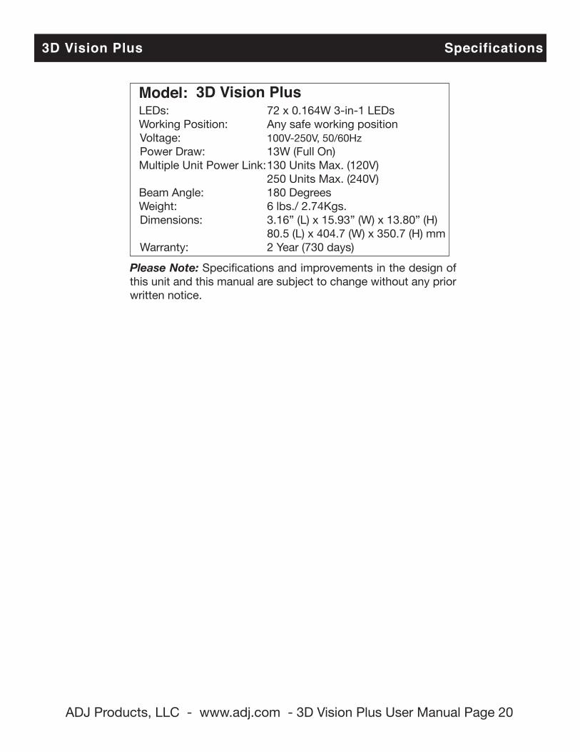
3D Vision Plus Specifications
Model: 3D Vision Plus LEDs: 72 x 0.164W 3-in-1 LEDs Working Position: Any safe working position Voltage: 100V-250V, 50/60Hz Power Draw: 13W (Full On) Multiple Unit Power Link: 130 Units Max. (120V) 250 Units Max. (240V) Beam Angle: 180 Degrees Weight: 6 lbs./ 2.74Kgs. Dimensions: 3.16” (L) x 15.93” (W) x 13.80” (H) 80.5 (L) x 404.7 (W) x 350.7 (H) mm Warranty: 2 Year (730 days)
Please Note: Specifications and improvements in the design of this unit and this manual are subject to change without any prior written notice.
ADJ Products, LLC6122 S. Eastern Ave. Los Angeles, CA 90040 USA
Tel: 323-582-2650 / Fax: 323-725-6100Web: www.adj.com / E-mail: [email protected]
A.D.J. Supply Europe B.V.Junostraat 2
6468 EW KerkradeNetherlands
[email protected] / www.adj.euTel: +31 45 546 85 00 / Fax: +31 45 546 85 99