35th gas-lift workshop houston, texas, usa … of self lift concept offshore nigeria . ... downhole...
TRANSCRIPT
Feb. 6 - 10, 2012 2012 Gas-Lift Workshop 1
Application of Self Lift Concept Offshore Nigeria
Olawale Ayeni, Lucky Ishomo & Mike Johnson
ExxonMobil Production Company
35th Gas-Lift Workshop Houston, Texas, USA February 6 – 10, 2012

Presentation Outline
• Field / Reservoir Overview
• Description of Gaslift Operations Offshore Nigeria
• Self-lift Concept & Drivers
• Design Considerations
• Case Studies & Results
• Conclusion
Feb. 6 - 10, 2012 2012 Gas-Lift Workshop 2
Feb. 6 - 10, 2012 2012 Gas-Lift Workshop 3
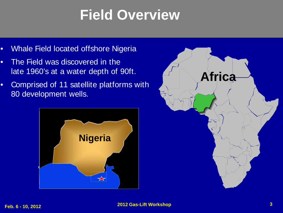
• Whale Field located offshore Nigeria
• The Field was discovered in the late 1960’s at a water depth of 90ft.
• Comprised of 11 satellite platforms with 80 development wells.
Field Overview
Africa
Nigeria
Map Area
Nigeria

Feb. 6 - 10, 2012 2012 Gas-Lift Workshop 4
Gas/Oil -5355’
Qua Iboe Shale
160’ Oil Column
Oil/Water -5515’
Disturbed Biafra
Well 4A
Well 30B
Competent Biafra
Base Qua Iboe (BQI)
Present Gas/Oil - 5375’
Gas/Oil-5355’TVD
160’ Oil Column
Oil/Water-5515’ TVD
Reservoir Overview Reservoir Information • Large gas cap with weak aquifer support. • Initial Reservoir Pressure of 2464 psi ,
Current pressure ~1850psi @ ~400 scf/bbl GOR.
• Voidage replacement being practiced through gas injection.
• Full-field pressure communication. Well Hydraulics • Average PI 50 – 120 Bbls / PSI /day. • Average manifold pressure varies between
250 – 400psi. • Gaslift required on most wells to sustain
flow.
0 5 10 15 20 25 30X X X X X X X~ X X X X X X
~ X X X X X~ X X X X
~ X X~ X
~1950
Reservoir Pressure (psi)
y yWater cut %
165017001750180018501900
Parameters
~
Unstable flow
Stable Flow
X
No flow
Hydraulic Table
Reservoir Cartoon / Fluid Contacts
Analysis based on 3-1/2” Tubing (Standard Tubing Size in the Field)
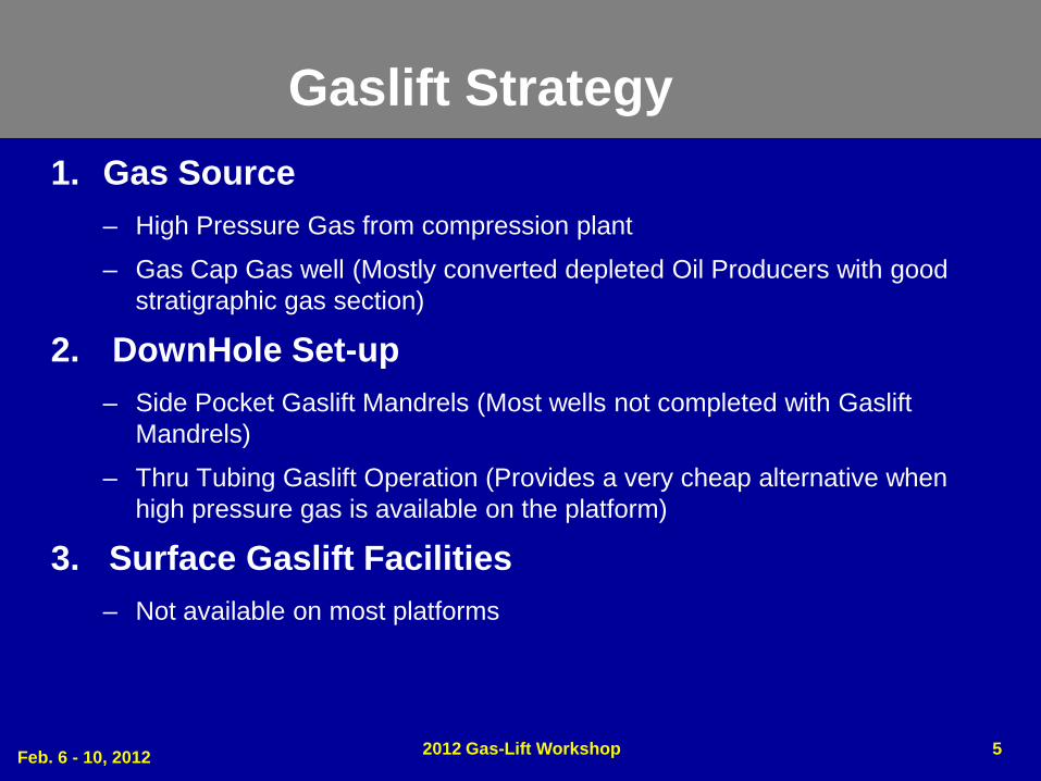
Gaslift Strategy 1. Gas Source
– High Pressure Gas from compression plant
– Gas Cap Gas well (Mostly converted depleted Oil Producers with good stratigraphic gas section)
2. DownHole Set-up – Side Pocket Gaslift Mandrels (Most wells not completed with Gaslift
Mandrels)
– Thru Tubing Gaslift Operation (Provides a very cheap alternative when high pressure gas is available on the platform)
3. Surface Gaslift Facilities – Not available on most platforms
5 Feb. 6 - 10, 2012 2012 Gas-Lift Workshop

• Gas lifting the lower zone - oil producer with gas from the upper zone -gas well; via a mandrel below the shallowest packer.
• Gaslift mandrel is fitted with a Venturi valve. Venturi valves have the ability to deliver the required gas thru-put within the available pressure differential.
• No Well Integrity Issues associated with Self–Lift.(Offshore environment)
Drivers
Concept of Self-Lift Gas Lift
• Delays in installation of surface gaslift facilities on surface platforms.
• Provides immediate uplift pending installation and commissioning of surface gaslift facilities.
• Offsets pre-investment in converting wells to gas source wells prior to the commissioning of gas lift facilities.
• Reduces dependency of gas source well workovers on rig schedule.
• Provides opportunities to mitigate gaps in the rig schedule.
Self-lift Concept & Drivers
Feb. 6 - 10, 2012 2012 Gas-Lift Workshop 6
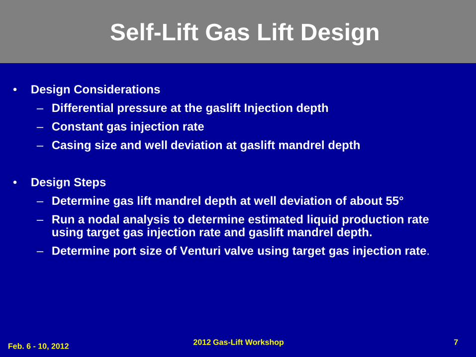
Self-Lift Gas Lift Design
• Design Considerations – Differential pressure at the gaslift Injection depth – Constant gas injection rate – Casing size and well deviation at gaslift mandrel depth
• Design Steps
– Determine gas lift mandrel depth at well deviation of about 55° – Run a nodal analysis to determine estimated liquid production rate
using target gas injection rate and gaslift mandrel depth. – Determine port size of Venturi valve using target gas injection rate.
Feb. 6 - 10, 2012 2012 Gas-Lift Workshop 7
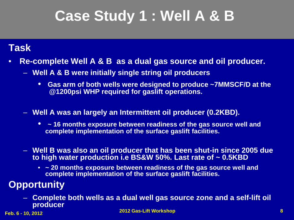
Case Study 1 : Well A & B
Task • Re-complete Well A & B as a dual gas source and oil producer.
– Well A & B were initially single string oil producers • Gas arm of both wells were designed to produce ~7MMSCF/D at the
@1200psi WHP required for gaslift operations.
– Well A was an largely an Intermittent oil producer (0.2KBD). • ~ 16 months exposure between readiness of the gas source well and
complete implementation of the surface gaslift facilities.
– Well B was also an oil producer that has been shut-in since 2005 due to high water production i.e BS&W 50%. Last rate of ~ 0.5KBD
• ~ 20 months exposure between readiness of the gas source well and complete implementation of the surface gaslift facilities.
Opportunity – Complete both wells as a dual well gas source zone and a self-lift oil
producer Feb. 6 - 10, 2012 2012 Gas-Lift Workshop 8
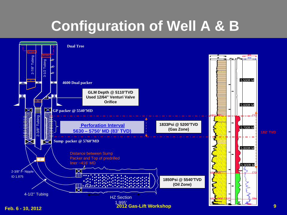
Configuration of Well A & B
9
Perforation Interval 5630 – 5750’ MD (83' TVD)
5,500ft MD
5,600ft MD
5,700ft MD
5,800ft MD
5,900ft MD
GP packer @ 5540’MD
Sump packer @ 5760’MD
scssv SCSSV
R
F
2-7/
8" T
ubin
g
3-1/
2 Tu
bing
4600 Dual packer
2-3/
8" T
ubin
g Dual Tree
F
HZ Section 1,995'
Distance between Sump Packer and Top of predrilled liner ~416’ MD
4-1/2’’ Tubing
2-3/8" F- Nipple ID 1.875
182’ TVD
1850Psi @ 5540’TVD (Oil Zone)
1833Psi @ 5200’TVD (Gas Zone)
GLM Depth @ 5110’TVD Used 12/64” Venturi Valve
Orifice
Feb. 6 - 10, 2012 2012 Gas-Lift Workshop

10
Well Test Plot for Well A
WELL NAME
CHK (1/64'')
WHP (Psig) BOPD G0R
(Scf/STB) BS&W
Well A
48 1200 1281 2281 15
52 1200 1345 2566 16
68 1210 1125 2531 16
60 1225 1203 2860 16
64 1210 1231 2660 17
Sensitivity of choke changes
• Venturi- Valve designed for max injection rate of 1.5MMSCF/D • Cumulative production as result of self lift was ~ 300KBO (Discounting base
production of 0.2KBD prior to self-lift) • Limited sensitivity on choke changes • Significant gas production observed 2009
Results of Well A
~ 16 Months Production Cum’ed ~300KBO
Shut-in due to HGOR
Feb. 6 - 10, 2012 2012 Gas-Lift Workshop

11
Well A – Pictures of Pulled Venturi Valve
Observations - Well A was shut-in 2010 due excessive gas production.
- Valve was pulled in August 2011, An orifice valve was installed in the upper mandrel.
- Severe erosion observed on the Venturi valve. This is likely caused by wet gas injection; root cause still being investigated.
Broken off section of the Valve Cross section of the valve showing some Erosion
Feb. 6 - 10, 2012 2012 Gas-Lift Workshop

Well B Self-lift Performance
12
- Successfully restored production at an average rate of ~ 1200 BOPD - Cumulative production during 20 months was ~ 650KBO - Gas production spiked late 2009. Plan in place to pull valve and operate from
the upper mandrels.
Well B Production Plot ~ 20 Months Production
Cum’ed ~650KBO
Shut-in due to High Gas
Production
Feb. 6 - 10, 2012 2012 Gas-Lift Workshop
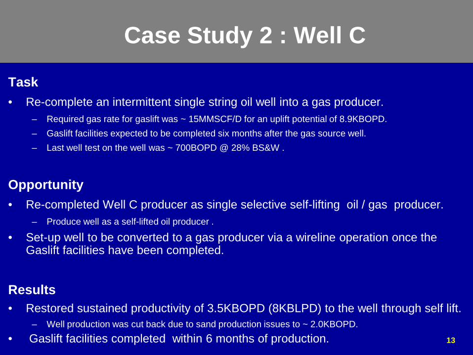
Case Study 2 : Well C
Task • Re-complete an intermittent single string oil well into a gas producer.
– Required gas rate for gaslift was ~ 15MMSCF/D for an uplift potential of 8.9KBOPD. – Gaslift facilities expected to be completed six months after the gas source well. – Last well test on the well was ~ 700BOPD @ 28% BS&W .
Opportunity • Re-completed Well C producer as single selective self-lifting oil / gas producer.
– Produce well as a self-lifted oil producer .
• Set-up well to be converted to a gas producer via a wireline operation once the Gaslift facilities have been completed.
Results • Restored sustained productivity of 3.5KBOPD (8KBLPD) to the well through self lift.
– Well production was cut back due to sand production issues to ~ 2.0KBOPD. • Gaslift facilities completed within 6 months of production.
13

Case Study 3 Continued
- Designed Ventri Valve for 1MMSCF/D. (Lessons learned from Well A&B) - Successfully converted the well to a gas producer via wireline operation
(Installed plug and opened the sliding sleeve) when surface facilities were completed.
R
SCSSV
4-1/
2’’ T
ubin
g
~200psi
Performance Curve for Venturi Valve (10/64” Port)
Feb. 6 - 10, 2012 2012 Gas-Lift Workshop 14

15
~ 6 Months Production Cumm’ed ~300KBO
- Successfully restored production at an average rate of ~ 1800 BOPD
- Cumulative production during 6 months was ~ 300KBO
Well C Self-lift Performance Well C Production Plot
Feb. 6 - 10, 2012 2012 Gas-Lift Workshop

Conclusion
• Application of self-lift concept has the potential of huge cost saving and benefits especially in offshore environment where several projects may not be synchronized.
• Potential of reducing gaslift project dependencies.
• Application of this concept has the potential of enhancing the economics for gaslift projects.
Feb. 6 - 10, 2012 2012 Gas-Lift Workshop 16
Feb. 6 – 10. 2012 2012 Gas-Lift Workshop 17
Copyright Rights to this presentation are owned by the company(ies) and/or author(s) listed on the title page. By submitting this presentation to the Gas-Lift Workshop, they grant to the Workshop, the Artificial Lift Research and Development Council (ALRDC), and the American Society of Mechanical Engineers (ASME), rights to:
– Display the presentation at the Workshop. – Place it on the www.alrdc.com web site, with access to the site to be as
directed by the Workshop Steering Committee. – Place it on a CD for distribution and/or sale as directed by the Workshop
Steering Committee. Other uses of this presentation are prohibited without the expressed written permission of the company(ies) and/or author(s) who own it and the Workshop Steering Committee.

Feb. 6 – 10, 2012 2012 Gas-Lift Workshop 18
Disclaimer The following disclaimer shall be included as the last page of a Technical Presentation or Continuing Education Course. A similar disclaimer is included on the front page of the Gas-Lift Workshop Web Site. The Artificial Lift Research and Development Council and its officers and trustees, and the Gas-Lift Workshop Steering Committee members, and their supporting organizations and companies (here-in-after referred to as the Sponsoring Organizations), and the author(s) of this Technical Presentation or Continuing Education Training Course and their company(ies), provide this presentation and/or training material at the Gas-Lift Workshop "as is" without any warranty of any kind, express or implied, as to the accuracy of the information or the products or services referred to by any presenter (in so far as such warranties may be excluded under any relevant law) and these members and their companies will not be liable for unlawful actions and any losses or damage that may result from use of any presentation as a consequence of any inaccuracies in, or any omission from, the information which therein may be contained. The views, opinions, and conclusions expressed in these presentations and/or training materials are those of the author and not necessarily those of the Sponsoring Organizations. The author is solely responsible for the content of the materials. The Sponsoring Organizations cannot and do not warrant the accuracy of these documents beyond the source documents, although we do make every attempt to work from authoritative sources. The Sponsoring Organizations provide these presentations and/or training materials as a service. The Sponsoring Organizations make no representations or warranties, express or implied, with respect to the presentations and/or training materials, or any part thereof, including any warrantees of title, non-infringement of copyright or patent rights of others, merchantability, or fitness or suitability for any purpose.