gas-lift application on low pressure gas well with … · gas-lift application on low pressure gas...
TRANSCRIPT

Gas Well Deliquification WorkshopSheraton Hotel, Denver, Colorado
February 23 - 26, 2009
Gas-Lift Application on Low Pressure Gas Well with Solid Production ProblemsPeter Oyewole
Adesola Adegoke
Louis Vigil
Jason Jones
Feb. 23 - 26, 2009 2009 Gas Well Deliquification Workshop Denver, Colorado
2
Outline
Historical background on a CBM Well Gas Lift Configuration Downhole Sensor Package (Cable-to-Surface) Case Study Real Time Data Capture Conclusion

Feb. 23 - 26, 2009 2009 Gas Well Deliquification Workshop Denver, Colorado
3
Why Gas Lift and CTS?
Liquid loading problems Pump failures due to coal fines sticking pumps Low reservoir pressures
Concerns about low Pwf & backpressure on the formation
Aid in removal of significant amounts of coal fines
Coal filters @ the inlet of separator
Installation of the gas lift requires real time monitoring and surveillance

Feb. 23 - 26, 2009 2009 Gas Well Deliquification Workshop Denver, Colorado
4
Prevent coal fines from clogging valve/orifices Minimize flowing bottom hole pressure
CBM reservoir requires very low flowing BHP to maximize production rates
Monitor Gas Lift System with downhole sensors.
obtain temperature and pressure measurements to optimize production and injection.
allows for performance evaluation
Completion Objectives
Feb. 23 - 26, 2009 2009 Gas Well Deliquification Workshop Denver, Colorado
5
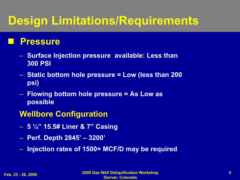
Design Limitations/Requirements Pressure
– Surface Injection pressure available: Less than 300 PSI
– Static bottom hole pressure = Low (less than 200 psi)
– Flowing bottom hole pressure = As Low as possible
Wellbore Configuration– 5 ½”
15.5# Liner & 7”
Casing– Perf. Depth 2845’
–
3200’– Injection rates of 1500+ MCF/D may be required
Feb. 23 - 26, 2009 2009 Gas Well Deliquification Workshop Denver, Colorado
6
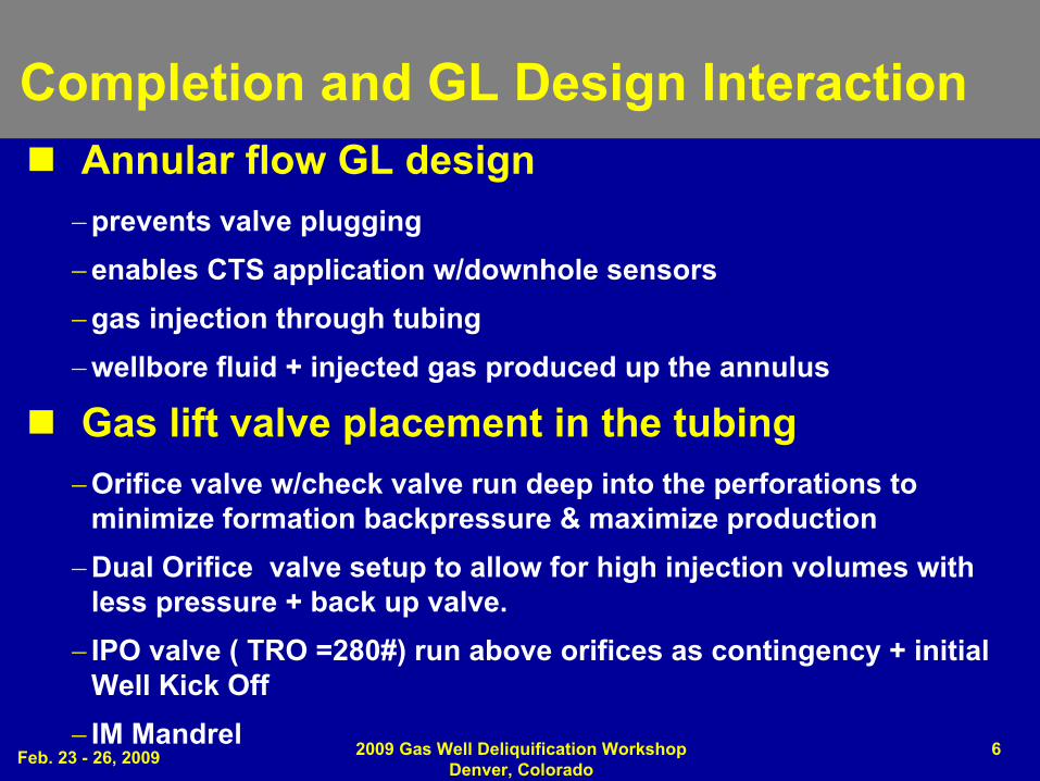
Completion and GL Design Interaction Annular flow GL design
prevents valve pluggingenables CTS application w/downhole sensorsgas injection through tubing wellbore fluid + injected gas produced up the annulus
Gas lift valve placement in the tubingOrifice valve w/check valve run deep into the perforations to
minimize formation backpressure & maximize productionDual Orifice valve setup to allow for high injection volumes with
less pressure + back up valve. IPO valve ( TRO =280#)
run above orifices as contingency + initial Well Kick Off
IM Mandrel

Feb. 23 - 26, 2009 2009 Gas Well Deliquification Workshop Denver, Colorado
7
Tubing size selection
2 3/8”
tubing inside of 5 1/2”
Liner & 2 7/8”
in 7”
casing with Bull plug
Annular flow will prevent coal fines from entering valves
Temperature/Pressure Monitor
Measure pressure in the tubing and casing @ the same depth
Placed near operating valve to measure ΔP across orifice
Completion and GL Design Interaction

Feb. 23 - 26, 2009 2009 Gas Well Deliquification Workshop Denver, Colorado
8
Surface set-up for Annular Gas Lift on Low Reservoir pressure well with lots of coal fines
Coal Fine Filter Bank

Feb. 23 - 26, 2009 2009 Gas Well Deliquification Workshop Denver, Colorado
9
Data
Two downhole pressure points & two surface pressure points
Production Conduit Gradient: as low as 0.013psi/ft (CP =14.4#, DHCP=56.8#)
Injection Gas Gradient: ~0.008psi/ft
Pressure drop across orifice: as low as 67psi during gas injection.
Actual data close to model results

Feb. 23 - 26, 2009 2009 Gas Well Deliquification Workshop Denver, Colorado
10
Phoenix Select Sensor –
Gas Lift
• Annulus Pressure• Tubing Pressure• Temperature• Vibration(x,y,z)• Current Leakage
Maximize draw down
Enables pressure build up transient analysis
Analyze injection point in real time
Single Pressure
Dual Pressure

Feb. 23 - 26, 2009 2009 Gas Well Deliquification Workshop Denver, Colorado
11
Case Study

Feb. 23 - 26, 2009 2009 Gas Well Deliquification Workshop Denver, Colorado
12
Down
hole
Repa
ir Co
sts
Repaired and Pump Failed
(after few days)
Historical Production Data & Repair CostInstalled Rod
PumpPump Failed Repaired
PumpPump Failed Annular Gas Lift
+ CTS gaugeConverted to Flow w/Flow
Controller
Po Boy Gas Lift

Feb. 23 - 26, 2009 2009 Gas Well Deliquification Workshop Denver, Colorado
13
Downhole Repair Costs
Cum. Production in 15months
-
Decrease in repair cost -
Decrease in production downtime
-
Increase in average revenue from cum. production
180,000 Mcfd

Feb. 23 - 26, 2009 2009 Gas Well Deliquification Workshop Denver, Colorado
14
What is behind Advanced Lifting Service?Trend From: 14/3/04 to: 10/9/04
0
200
400
600
800
1000
1200
1400
1600
1800
2000
14-Mar-04 0:00 03-Apr-04 0:00 23-Apr-04 0:00 13-May-04 0:00 02-Jun-04 0:00 22-Jun-04 0:00 12-Jul-04 0:00 01-Aug-04 0:00 21-Aug-04 0:00 10-Se
IOPo
int V
alue
Intake Pressure Discharge Pressure
k = 98 mdSkin = +3
SurveillanceLIFTWatcher*
• Reduce downtime• Find Production
Opportunities• Minimize liquid loading• Maximize sales gas rates.
Inflow Analysis• Formation damage• Reservoir pressure• Field Optimization
1700
1900
2100
2300
2500
2700
2900
Tota
l Liq
uid
Rate
s [ST
B/D
]
0 100 200 300 400Time (days)
0
10000
20000
30000
40000
50000
60000
70000
80000
90000
100000
Oil
Cum
Pro
duct
ion
Oil Cum Production 500.00ft (STB)Oil Cum Production 400.00ft (STB)Oil Cum Production 300.00ft (STB)Oil Cum Production 200.00ft (STB)Oil Cum Production 100.00ft (STB)
ProCADE*
*Mark of Schlumberger
Single Layer Forecast: Sensitized Oil Cum Productions vs Time
AethonNEVU 13-1Simulated11/15/2004
0 100 200 300 400 500 600 700 8000
00
200
300
400
500
600
700
800
900
000
Liquid Rate, Bbl/D Not Used
t Used Not Used t Used Not Used
11 2
Skin Sensitivity(1) 4.000(2) 0.000
Match Point – Skin =4
Q=475 BLPD
Production Prediction, Skin=0
Q=700 BLPD
0 100 200 300 400 500 600 700 8000
00
200
300
400
500
600
700
800
900
000
Liquid Rate, Bbl/D Not Used
t Used Not Used t Used Not Used
11 2
Skin Sensitivity(1) 4.000(2) 0.000
Match Point – Skin =4
Q=475 BLPD
Production Prediction, Skin=0
Q=700 BLPD
Match Point – Skin =4
Q=475 BLPD
Production Prediction, Skin=0
Q=700 BLPD
25 bopd
Production Improvement• Recommend remedial actions• Predict associated production
Diagnostic Analysis• Alarm Based• Event Based• Proactive Opportunity
Outflow AnalysisPipesim*
• Appropriate valve sizing• GL Method Selection• Optimize injection rates
Advanced Lifting Services consists of expertise (people and processes) and technology focused on improving production.
Feb. 23 - 26, 2009 2009 Gas Well Deliquification Workshop Denver, Colorado
15
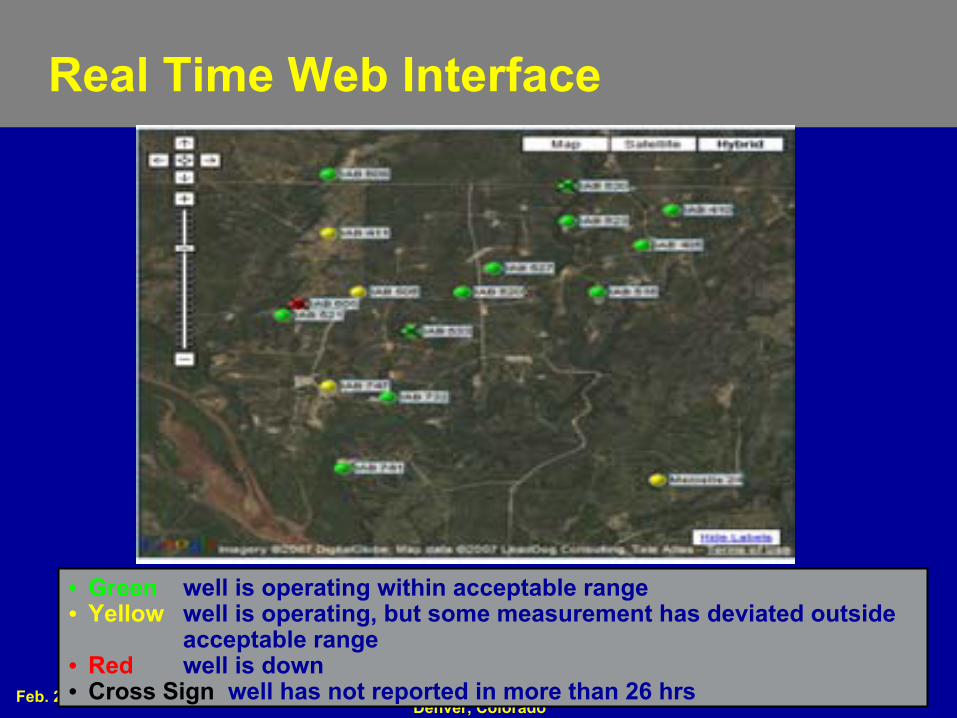
• Green
well is operating within acceptable range• Yellow
well is operating, but some measurement has deviated outside acceptable range
• Red
well is down• Cross Sign
well has not reported in more than 26 hrs
Real Time Web Interface

Feb. 23 - 26, 2009 2009 Gas Well Deliquification Workshop Denver, Colorado
16
Real Time Gas Lift Trends
Feb. 23 - 26, 2009 2009 Gas Well Deliquification Workshop Denver, Colorado
17
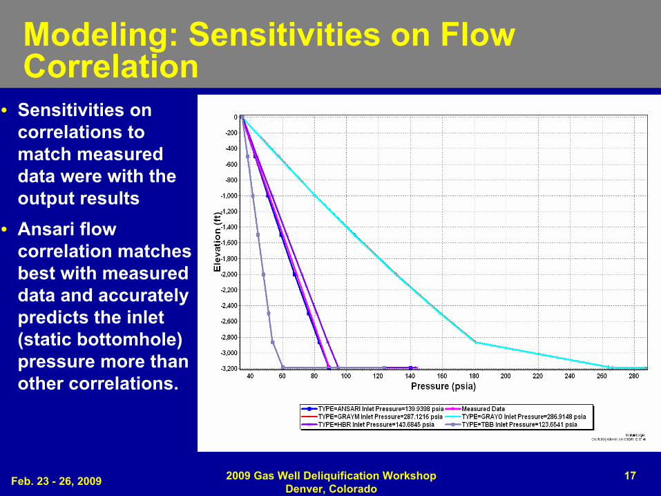
Modeling: Sensitivities on Flow Correlation
• Sensitivities on correlations to match measured data were with the output results
• Ansari flow correlation matches best with measured data and accurately predicts the inlet (static bottomhole) pressure more than other correlations.

Feb. 23 - 26, 2009 2009 Gas Well Deliquification Workshop Denver, Colorado
18
Nodal Analysis

Feb. 23 - 26, 2009 2009 Gas Well Deliquification Workshop Denver, Colorado
19
Sales Gas & Injection Gas Rates

Feb. 23 - 26, 2009 2009 Gas Well Deliquification Workshop Denver, Colorado
20
Inflow Analysis
Downhole Production Pressure
Test Type Build Up
Reservoir Model HomogenousInfinite Acting
Ext.Reservoir
Pressure (psia) @ gauge depth
(3,145’
MD)
150
Effective Permeability (md)
60
Total Skin ~0

Feb. 23 - 26, 2009 2009 Gas Well Deliquification Workshop Denver, Colorado
21
Conclusions
Maximized injection gas rates while maintaining production
Cum Gas Production for given period with Gas Lift Application is higher than that of Rod Pump as a result of pump failure and downtime (~180 MMcf
more).
Significant rod pump repair costs of ~$300K eliminated by converting to gas lift
CTS gauge provided data for well performance monitoring and optimization in real time
Feb. 23 - 26, 2009 2009 Gas Well Deliquification Workshop Denver, Colorado
22
QUESTION S

Feb. 23 - 26, 2009 2009 Gas Well Deliquification Workshop Denver, Colorado
23
CopyrightRights to this presentation are owned by the company(ies) and/or author(s) listed on the title page. By submitting this presentation to the Gas Well Deliquification Workshop, they grant to the Workshop, the Artificial Lift Research and Development Council (ALRDC), and the Southwestern Petroleum Short Course (SWPSC), rights to:
– Display the presentation at the Workshop.– Place it on the www.alrdc.com
web site, with access to the site to be as directed by the Workshop Steering Committee.
– Place it on a CD for distribution and/or sale as directed by the
Workshop Steering Committee.
Other uses of this presentation are prohibited without the expressed written permission of the company(ies) and/or author(s) who own it and the Workshop Steering Committee.
Feb. 23 - 26, 2009 2009 Gas Well Deliquification Workshop Denver, Colorado
24
DisclaimerThe following disclaimer shall be included as the last page of a
Technical Presentation or Continuing Education Course. A similar disclaimer is included on the front page of the Gas Well Deliquification Web Site.The Artificial Lift Research and Development Council and its officers and trustees, and the Gas Well Deliquification Workshop Steering Committee members, and their supporting organizations and companies (here-in-after referred to as the Sponsoring Organizations), and the author(s) of this Technical Presentation or Continuing Education Training Course and their company(ies), provide this presentation and/or training material at the Gas Well Deliquification Workshop "as is" without any warranty of any kind, express or implied, as to the accuracy of the information or the products or services referred to by any presenter (in so far as such warranties may be excluded under any relevant law) and these members and their companies will not be liable for unlawful actions and any losses or damage that may result from use of any
presentation as a consequence of any inaccuracies in, or any omission from, the information which therein may be contained.The views, opinions, and conclusions expressed in these presentations and/or training materials are those of the author and not necessarily those of the Sponsoring Organizations. The author is solely responsible for the content of the materials.The Sponsoring Organizations cannot and do not warrant the accuracy of these documents beyond the source documents, although we do make every attempt to work from authoritative sources. The Sponsoring Organizations provide these presentations and/or training materials as a service. The Sponsoring Organizations make no representations
or warranties, express or implied, with respect to the presentations and/or training materials, or any part thereof, including any warrantees of title, non-infringement of copyright or patent rights of others, merchantability, or fitness or suitability for any purpose.