30rh 040-240 “b” - acare · the receiver/heat exchanger (carrier patent) enhances relia-bility...
TRANSCRIPT

The 30RH Aquasnap heat pumps feature the latest techno-logical innovations: ecological refrigerant HFC-407C, scroll compressors, low-noise fans made of a composite material and microprocessor control. The refrigerant circuit with its patented receiver/heat exchanger, and the auto-adaptive Pro-Dialog control system guarantee reliable and economical operation in all climates from -10°C to 45°C. Aquasnap includes a complete hydronic module as stan-dard, simplifying the installation to straightforward opera-tions like connection of the power supply and the water supply and return piping.
Features
�
Integrated hydronic module for fast installation, incorporat-ing all hydronic components: removable screen filter, water pump with high available pressure, expansion tank, water flow switch, safety valve, pressure gauges, and purge valve. A throttle valve allows adjustment of the water flow in accordance with the characteristics of the installation. All components are protected against frost down to -20°C.
�
Low-volume water loop: the auto-adaptive algorithm con-trols the water temperature and eliminates any risk of excessive compressor cycling. In the majority of comfort air conditioning applications a buffer tank is unnecessary.The low water volume reduces the energy consumption during changeover from heating to cooling during in-between seasons.
�
Ecological refrigerant HFC-407C: no effect on the ozone layer, replaces R-22 in air conditioning applications with small and medium capacities. Extensively tested by Carrier for several years, it offers the same performance and relia-bility guarantees as R-22.
�
The receiver/heat exchanger (Carrier patent) enhances relia-bility and performance of the 30RH heat pump. In the heat-ing mode the refrigerant is condensed in the receiver at the plate heat exchanger outlet. This device compensates for large differences in volume between the coil and the water heat exchanger (plate heat exchanger). It ensures an ideal refrigerant charge in heating and cooling mode and perfect control of subcooling or superheating. Compressor life is increased (no risk of refrigerant migration into the compres-sor), and the use of the heat exchangers is maximised.
�
The revolutionary, low-noise, two-speed Flying Bird II fan is made of composite recyclable material and employs a multi-blade design and a rotating shroud, as used in the aeronautical industry. It is exceptionally quiet, and does not generate the low-frequency noise, irritating to the human ear. At part load or low outdoor temperatures the fan auto-matically switches to the low speed. To reduce the operat-ing noise even further, the fan is not fixed to the top unit panel, but supported by an extremely rigid tower chassis.
�
Defrost is optimised by the auto-adaptive algorithm. This and the new coil design reduce the defrost cycle duration by an average of 50%. For increased safety an electric heater prevents accumulation of ice on the air heat exchanger base.
AQUASNAP
30RH 040-240 “B”
Nominal cooling capacity 38-210 kWNominal heating capacity 39-229 kW
Air-to-Water Heat Pumps with Integrated Hydronic Module
Carrier is participating in the Eurovent CertificationProgramme. Products are as listed in the EuroventDirectory of Certified Products.

�
Quiet, vibration-free scroll compressors, durable and maintenance-free. The use of several compressors per circuit (from size 30RH 050) reduces the start-up current and the power consumption at part load.
�
The refrigerant circuit is completely leak-proof for life. All pipes and refrigeration components are welded. Pressure sensors, mounted directly on the pipes, take the place of the pressure switches and their capillary tubes, a source of leaks in the past.
�
From size 30RH 090 upwards, two independent refrigerant circuits ensure partial cooling/heating capacity in all circumstances.
�
Electrical connections are simplified, and the standard Aquasnap equipment includes a main disconnect switch, and a single entry point of the three-phase without neutral power supply to the whole unit.
�
Large removable panels and the hinged door of the control box ensure perfect accessibility and permit easy access to all components. Furthermore an opening allows adjustments to be made without interrupting the operation of the unit. For the most important maintenance operations the unit top cover is easily removed, and total access from above is possible, with the fan remaining in place.
�
The electric resistance heater control module (accessory) permits control of up to four stages of electric heat for supplementary heating at low outdoor temperatures.
�
The evaporator is a welded, stainless steel plate heat exchanger, maximising the thermodynamic properties of HFC-407C and offering considerably increased performances as well as low water-side pressure drops.From size 30RA 090 upwards the units are equipped with a twin-circuit interlaced heat exchanger for safe operation at part load. When the unit is shut down, the heat exchanger is protected against freeze-up by a trace heater.
PRO-DIALOG Plus control
PRO-DIALOG Plus is an advanced numeric control system that combines complex intelligence with great operating simplicity. PRO-DIALOG Plus constantly monitors all machine parameters, optimising the operation of compressors, fans, cycle reversing valve and water pump.
A powerful control system
�
The Pro-Dialog Plus control is auto-adaptive and guarantees total protection of the compressors. The system permanently checks the operating parameters and responds to avoid excessive cycling and maintain the ideal operating range for the compressor (temperatures and pressures out of range etc.). By taking corrective action before the fault occurs, the auto-adaptive control frequently prevents a shutdown of the heat pump due to a fault condition.
�
To optimise power consumption, PRO-DIALOG Plus automatically resets the chilled water temperature set-point in accordance with the outdoor air temperature or the return water temperature or uses a second set-point (example occupied/unoccupied) and ensures automatic heating/cooling changeover.
�
The system also controls the start-up of a boiler relay or manages a supplementary electric heater (accessory).
Clear and easy-to-use control system
�
The operator interface is clear and user-friendly: LEDs and two numeric displays ensure immediate verification of all unit operating data.
�
Buttons conveniently positioned on a synoptic heat pump diagram offer immediate display of the operating parameters: temperatures, pressures, set point, run times etc.
�
10 menus offer direct access to all machine controls, including a history of possible faults, for rapid and complete heat pump fault diagnosis.
Extended communications capabilities
�
PRO-DIALOG Plus allows remote control. Volt-free contacts regulate: start/stop, cooling/heating mode selection, power demand limit or selection of the second set point. The system permits remote signalling of any possible anomaly for each refrigerant circuit.
�
The internal clock permits programming of:- heat pump start/stop- operation at the second set-point (e.g. unoccupied room)- operation of the chiller with the fan at low speed to
reduce the noise level.
�
Master/slave control of two chillers operating in parallel with operating time equalisation.
�
RS 485 serial port for remote chiller control via communications bus.
PRO-DIALOG Plus operator interface
1
2
3
4
5
6
75
8
10
11
9
18
15
1714
1417
15
16
13
19
13
12
3
6
7
2
1
24
23
16
14
9
21
20
8
4
22
5
Options and accessories
Option Accessory
Condenser anti-corrosion pre-treatment for marine applications X
Electronic compressor starter for reduction of start-up current (30RH 040-080) X
Unit without hydronic module X
Hydronic module with dual pump X
Supplementary electric resistance heater control board (3 stages + 1 emergency stage) X
Communications board with open JBus protocol X X
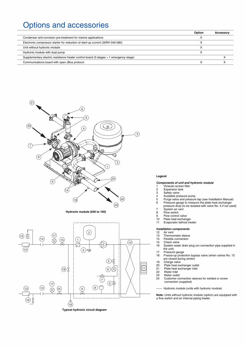
Legend
Components of unit and hydronic module
1 Victaulic screen filter2 Expansion tank3 Safety valve4 Available pressure pump5 Purge valve and pressure tap (see Installation Manual)6 Pressure gauge to measure the plate heat exchanger
pressure drop (to be isolated with valve No. 5 if not used)7 System air vent8 Flow switch9 Flow control valve10 Plate heat exchanger11 Evaporator defrost heater
Installation components
12 Air vent13 Thermometer sleeve14 Flexible connection15 Check valve16 System water drain plug (on connection pipe supplied in
the unit)17 Pressure gauge18 Freeze-up protection bypass valve (when valves No. 15
are closed during winter)19 Charge valve20 Plate heat exchanger outlet21 Plate heat exchanger inlet22 Water inlet 23 Water outlet24 Customer connection sleeves for welded or screw
connection (supplied)
------ Hydronic module (units with hydronic module)
Note:
Units without hydronic module (option) are equipped with a flow switch and an internal piping heater.
Typical hydronic circuit diagram
Hydronic module (040 to 160)

Physical data
30RH 040 050 060 070 080 090 100 120 140 160 200 240
Nominal cooling capacity*
kW 38.3 44.5 54.0 66.0 71.0 83.0 92.0 108.0 132.0 142.0 179.0 210.0
Nominal heating capacity**
kW 39.2 47.3 58.0 67.0 80.0 87.0 98.0 117.0 133.0 160.0 194.0 229.0
Operating weight, with hydronic module
kgSingle pump 566 624 647 661 691 1183 1196 1238 1312 1368 2233 2405Dual pump kg 646 704 727 741 768 1260 1273 1338 1412 1468 2321 2493Unit without hydronic module 542 600 623 637 665 1152 1165 1200 1274 1330 2086 2258
Refrigerant charge
R-407CCircuit A kg 10.9 11.5 15.1 16.7 19.5 11.4 11.8 15.6 17.4 20.3 22.5 29.5Circuit B kg -
-
- - - 12.0 15.6 15.6 17.4 20.3 29.5 29.5
Compressors
Hermetic scroll compressor, 48.3 r/sQuantity, circuit A 1 2 2 2 2 1 1 2 2 2 2 3Quantity, circuit B - - - - - 2 2 2 2 2 3 3No. of capacity steps 1 2 2 2 2 3 3 4 4 4 5 6Minimum capacity % 100 46 42 50 50 25 25 21 25 25 20 16.5
Control type
PRO-DIALOG Plus
Air heat exchangers
Grooved copper tubes, aluminium finsFans Axial Flying Bird II fans with rotating shroudQuantity 1 1 1 1 1 2 2 2 2 2 4 4Total air flow (high speed) l/s 3870 3660 4080 5600 5600 7350 7950 8160 11200 11200 17343 20908Speed (high/low speed) r/s 11.5/5.8 11.5/5.8 11.5/5.8 15.6/7.8 15.6/7.8 11.5/5.8 11.5/5.8 11.5/5.8 15.6/7.8 15.6/7.8 11.5/5.8 15.6/7.8
Water heat exchangers
Direct-expansion welded plate heat exchangerWater volume l 3.6 4.6 5.9 6.5 7.6 7.2 8.2 9.8 11.4 13.0 26.8 26.8Max. water-side operating pressure kPaOption without hydronic module 1000 1000 1000 1000 1000 1000 1000 1000 1000 1000 1000 1000Unit with hydronic module 300 300 300 300 300 300 300 300 300 300 400 400
Hydronic module
Pump (single centrifugal, 48.3 r/s) Monocell composite pump Monocell pumpQuantity 1 1 1 1 1 1 1 1 1 1 1 1Expansion tank volume l 12 12 12 12 12 35 35 35 35 35 35 35Expansion tank pressure kPa 100 100 100 100 100 150 150 150 150 150 150 150
Water connections
(with and without hydronic module)Victaulic (sleeves for welding or screw connections supplied) Threaded male
gas connectionsDiameter in 2 2 2 2 2 2 2 2-1/2 2-1/2 2-1/2 3 3Outside tube diameter mm 60.3 60.3 60.3 60.3 60.3 60.3 60.3 76.1 76.1 76.1 88.9 88.9
Legend
* Nominal conditions: water heat exchanger entering/leaving temperature 12°C/7°C, outdoor air temperature 35°C.** Nominal conditions: air heat exchanger entering/leaving temperature 40°C/45°C, outdoor air dry bulb temperature 7°C.
Sound levels
30RH 040 050 060 070 080 090 100 120 140 160 200 240
Sound power, dB(A) 10
-12
W
82 82 82 86 87 85 85 85 89 90 91 92
According to Eurovent 8/1 (derived from ISO standard 3744 or ISO 9614-1).

Electrical data
* Power input of the compressor(s) + fan(s) at maximum unit operating conditions: entering/leaving water temperature = 15°C/10°C, maximum condensing temperature of 67.8°C and 400 V nominal voltage (values given on the unit name plate).
** Nominal unit operating current draw at the following conditions: evaporator entering/leaving water temperature 12°C/7°C, outdoor air temperature 35°C. The current values are given at 400 V nominal voltage.
*** Maximum unit operating current at maximum unit power input and 360 V nominal voltage.**** Maximum unit operating current at maximum unit power input and 400 V nominal voltage (values given on the unit name plate).
† Maximum instantaneous starting current at 400 V nominal voltage and with compressor in across-the-line-start (maximum operating current of the smallest compressor(s) + fan current + locked rotor current of the largest compressor).
‡ Maximum instantaneous starting current at 400 V nominal voltage and with compressor with electronic starter (maximum operating current of the smallest compressor(s) + fan current + reduced start-up current of the largest compressor).
Note:
The water pump power input values are given for guidance only.* To obtain the maximum power input for a unit with hydronic module add the maximum unit power input from the top table to the pump power input (*) from the table above.
** To obtain the maximum unit operating current draw for a unit with hydronic module add the maximum unit current draw from the top table to the pump current draw from the table above.
30RH (without hydronic module) 040 050 060 070 080 090 100 120 140 160 200 240
Power circuit
Nominal power supply V-ph-Hz 400-3-50Voltage range V 360-440
Control circuit supply
The control circuit is supplied via the unit-mounted transformer
Maximum unit power input*
kW 20.3 24.6 30.1 35.2 40.0 44.2 49.6 60.5 70.7 79.7 104.3 124.9
Nominal unit current draw**
A 28.0 34.7 41.2 47.0 54.3 62.7 69.1 82.3 94.1 108.6 140.3 168.7
Maximum unit current draw at 360 V***
A 37.0 45.7 54.9 62.7 72.4 82.6 91.9 109.8 125.4 144.8 185.4 222.9
Maximum unit current draw at 400 V****
A 33.6 41.4 49.7 57.0 65.7 75.1 83.4 99.5 113.9 131.3 168.7 202.8
Maximum start-up current
Standard unit† A 158.4 151.0 168.9 176.1 190.4 199.8 208.1 218.6 233.0 256.1 293.4 327.6With electronic starter control‡ A 99.0 101.0 113.0 120.0 132.0 - - - - - - -
Holding current for three-phase short circuits
kA 6 6 6 6 6 10 10 10 10 10 19 19
Hydronic module 040 050 060 070 080 090 100 120 140 160 200 240
Single pump
Shaft power kW 0.75 0.75 0.75 0.75 1.1 1.1 1.1 1.85 1.85 1.85 5.5 5.5Power input* kW 1.1 1.1 1.1 1.1 1.4 1.4 1.4 2.5 2.5 2.5 6.6 6.6Maximum current draw at 400 V** A 2.1 2.1 2.1 2.1 3.1 3.1 3.1 5.0 5.0 5.0 10.9 10.9
Dual pump
Shaft power kW 2.2 2.2 2.2 2.2 2.2 2.2 2.2 3.0 3.0 3.0 5.5 5.5Power input* kW 2.7 2.7 2.7 2.7 2.7 2.7 2.7 4.0 4.0 4.0 6.6 6.6Maximum current draw at 400 V** A 4.7 4.7 4.7 4.7 4.7 4.7 4.7 6.6 6.6 6.6 10.9 10.9
Electrical data notes:
• 30RH 040-240 units have a single power connection point located at the main switch.
• The control box includes the following standard features:- a main disconnect switch, starter and motor protection devices for each compressor, the fan, the optional pumps
- the control devices• Field connections:
All connections to the system and the electrical installations must be in full accordance with all applicable local codes.
• The Carrier 30RH units are designed and built to ensure conformance with these codes. The recommendations of European standard EN 60204-1 (corresponds to IEC 60204-1) (machine safety - electrical machine components - part 1: general regulations) are specifically taken into account, when designing the electrical equipment.
NOTES:
• Generally the recommendations of IEC 60364 are accepted as compliance with the requirements of the installation directives. Conformance with EN 60 204 is the best means of ensuring compliance with the Machines Directive § 1.5.1.
• Annex B of EN 60204-1 describes the electrical characteristics used for the operation of the machines.
1. The operating environment for the 30RH units is specified below:a. Environment* - Environment as classified in EN 60721 (corresponds to IEC
60721):- outdoor installation*
- ambient temperature range: -10°C to +45°C ± 1 K, class 4K3*- altitude:
≤
2000 m- presence of hard solids, class 4S2 (no significant dust present)- presence of corrosive and polluting substances, class 4C2 (negligible)- vibration and shock, class 4M2
b. Competence of personnel, class BA4* (trained personnel - IEC 60364)2. Power supply frequency variation: ± 2 Hz.3. The neutral (N) conductor must not be connected directly to the unit (if
necessary use transformers)4. Over-current protection of the power supply conductors is not provided with
the unit.5. The factory-installed disconnect switches/circuit breakers are of a type that
is suitable to interrupt the power in accordance with EN60947-3 (corresponds to IEC 60947-3).
6. The units are designed for connection to TN networks (IEC 60364). For IT networks the earth connection must not be at the network earth. Provide a local earth, consult competent local organisations to complete the electrical installation.
NOTE:If particular aspects of an actual installation do not conform to the conditions described above, or if there are other conditions which should be considered, always contact your local Carrier representative.
* The required protection level for this class is IP43BW (according to reference document IEC 60529). All 30RH units are protected to IP44CW and fulfil this protection condition.

Operating limits
Notes
:* Maximum flow rate for an available pressure of 50 kPa (unit with hydronic module)
** Maximum flow rate for a pressure drop of 100 kPa (unit without hydronic module)† For applications requiring operation below 7.8°C contact Carrier‡ For applications requiring operation below 5°C anti-freeze must be used
Heat exchanger water flow rate, l/s
30RH
Min. water flow Max. water flow* Max. water flow**Single pump Dual pump
040
1.0 3.5 4.4 3.7
050
1.1 4.0 5.2 4.6
060
1.4 4.4 6.0 5.8
070
1.5 4.6 6.4 6.4
080
1.7 5.5 6.8 7.3
090
2.3 5.6 6.9 7.6
100
2.6 5.8 7.4 8.8
120
3.1 8.5 10.5 10.8
140
3.5 8.8 11.4 12.7
160
4.2 9.1 11.9 14.4
200
5.3 23.4 23.4 24.2
240
6.3 23.4 23.4 24.2
Heating mode
30RH040 - 240
Entering water temperatureat start-up, ˚C
Entering water temperatureat shut-down, ˚C
Leaving water temperatureduring operation, °C
Entering air temperature, °C
Minimum † Maximum Minimum Maximum Minimum ‡ Maximum Minimum Maximum
10 45 3 60 20 50 -10 40
Cooling mode
30RH040 - 240
Entering water temperatureat start-up, ˚C
Entering water temperatureat shut-down, ˚C
Leaving water temperatureduring operation, °C
Entering air temperature, °C
Minimum †, Maximum Maximum Minimum ‡ Maximum Minimum Maximum
7,8 30 60 5 15 -10 46
0 1 2 3 4 5 6 7 8 9 10 ˚C
46
4544.5
44
0
-10
˚C ˚C
20
15
10
5
0
-5
-10
20 25 30 35 40 45 50 ˚C
25
30
35
40
Ent
erin
g ai
r te
mpe
ratu
re
Leaving water temperature
Operating range in cooling mode
Notes:
1. Water heat exchanger
∆
t = 5 K2. The water heat exchanger and the hydronic module are protected against frost down to -20°C.
Operating range with required anti-freeze solution and special Pro-Dialog control configuration
Ent
erin
g ai
r te
mpe
ratu
re
Leaving water temperature
Operating range in heating mode

Available static system pressure
Single pump
Water flow rate, l/s
Ava
ilabl
e st
atic
pre
ssur
e, k
Pa
50
75
100
125
150
175
200
225
250
275
300
325
1 2 3
4
5 6 7 8 9 10
0 2 4 6 8 10 12 14 16 18 20 22 24
25
50
75
100
125
150
175
200
225
250
275
300
325
0 2 4 6 8 10 12 14 16 18 20 22 24
251 2 3 4 5
6
7
8 9 10 11
Legend
1 30RH 0402 30RH 0503 30RH 0604 30RH 0705 30RH 080-090
6 30RH 1007 30RH 1208 30RH 1409 30RH 16010 30RH 200-240
Dual pump
Water flow rate, l/s
Ava
ilabl
e st
atic
pre
ssur
e, k
Pa
Legend
1 30RH 0402 30RH 0503 30RH 0604 30RH 0705 30RH 080 6 30RH 090
7 30RH 1008 30RH 1209 30RH 14010 30RH 16011 30RH 200-240

Water loop volume
Minimum water loop volume
Volume = CAP (kW) x N* = litres, where CAP is the nominal cooling capacity at nominal operating conditions.
NOTE:
For industrial process cooling applications, where high stability of the water temperature must be achieved, the values above must be increased.
Air conditioning application N*
30RH 040 3.530RH 050 to 240 2.5
Industrial process cooling
30RH 040 to 240 See note
Maximum water loop volume
Units with hydronic module incorporate an expansion tank that limits the water loop volume. The table below gives the maximum loop volume for pure water or ethylene glycol with various concentrations.
30RH 040-080 (in litres)
30RH 090-160(in litres)
30RH200-240(in litres)
Pure water
600 1500 2000
10% ethylene glycol
450 1200 1600
20% ethylene glycol
400 1000 1400
35% ethylene glycol
300 800 1000
1081
1329
2071
1000
1000
1
2
1
2
1000
1000
Dimensions/clearances
30RH 040-080
Legend:
All dimensions are given in mm.
Control box
Required clearances for air entry
Required clearances for maintenance
Water inlet
Water outlet
Power cable entry
Air outlet, do not obstruct
NOTE:
Drawings are not contractually binding. Before designing an installation, consult the certified dimensional drawings, available on request.

2279 3351
1674
2
1
1
1
1
2
1000
1000
1000
2
2
1000
20712278
1329
1000
1000
1000
1000
2
1
1
1
1
2
Dimensions/clearances
30RH 090-160
30RH200-240
Legend:
All dimensions are given in mm.
Control box
Required clearances for air entry
Required clearances for maintenance
Water inlet
Water outlet
Power cable entry
Air outlet, do not obstruct
NOTE:
Drawings are not contractually binding. Before designing an installation, consult the certified dimensional drawings, available on request.
Heating capacities, single and dual pumps
30
RH
En
teri
ng
air
tem
per
atu
re, °
C
LWT
-10
-50
710
CA
PC
OM
PU
NIT
CO
ND
PR
ES
PR
ES
CA
PC
OM
PU
NIT
CO
ND
PR
ES
PR
ES
CA
PC
OM
PU
NIT
CO
ND
PR
ES
PR
ES
CA
PC
OM
PU
NIT
CO
ND
PR
ES
PR
ES
CA
PC
OM
PU
NIT
CO
ND
PR
ES
PR
ES
(1)
(2)
(1)
(2)
(1)
(2)
(1)
(2)
(1)
(2)
˚CkW
kWkW
l/skP
akP
akP
akW
kWkW
l/skP
akP
akP
akW
kWkW
l/skP
akP
akP
akW
kWkW
l/skP
akP
akP
akW
kWkW
l/skP
akP
akP
a
04
0
3022
.78.
799.
991.
0910
162
207
25.9
8.85
10.1
1.24
1315
920
531
9.22
10.4
1.48
1815
320
042
.110
.111
.32.
0133
136
185
45.6
10.3
11.5
2.18
3912
917
9
05
0
27.7
11.3
12.5
1.32
916
220
831
.611
.412
.61.
5112
159
206
37.8
11.8
131.
8117
152
201
5412
.513
.72.
635
126
181
5812
.713
.92.
7739
119
175
06
0
3413
.414
.61.
629
161
208
38.8
13.5
14.7
1.85
1115
720
646
.314
15.2
2.21
1614
920
063
14.8
163.
0129
123
182
6815
16.2
3.23
3411
417
6
07
0
38.8
14.7
17.2
1.85
915
920
744
.314
.917
.42.
1212
154
204
5315
.518
2.53
1714
319
770
16.9
19.4
3.36
3011
417
876
17.1
19.6
3.64
3610
117
0
08
0
46.5
1820
.52.
2210
199
205
5318
.120
.62.
5313
191
201
6318
.921
.43.
0319
175
192
8619
.922
.44.
0935
132
165
9220
.122
.64.
3940
117
155
09
0
5020
.122
.52.
4113
193
202
5820
.222
.62.
7516
184
196
6921
.123
.53.
2923
166
186
9722
.725
.14.
6143
107
149
104
2325
.44.
9549
8913
8
10
0
5722
.224
.62.
7112
188
200
6522
.424
.83.
0916
177
194
7723
.325
.73.
6922
156
182
105
24.9
27.3
5.02
3896
146
113
25.3
27.7
5.41
4475
133
12
0
6826
.829
.23.
2512
217
196
7827
29.4
3.71
1521
019
293
28.1
30.5
4.43
2119
618
512
629
.632
6.02
3715
216
213
530
32.4
6.46
4213
715
5
14
0
7829
.534
.53.
7111
213
195
8929
.734
.74.
2315
204
191
106
3136
5.06
2018
718
314
133
.738
.76.
7234
138
160
152
34.3
39.3
7.27
3911
815
0
16
0
9336
414.
4413
203
192
106
36.2
41.2
5.07
1619
018
612
737
.742
.76.
0622
165
175
171
39.7
44.7
8.17
3990
142
184
40.3
45.3
8.78
4464
130
20
0
115
46.5
545.
487
282
282
138
47.6
556.
5710
275
275
163
49.3
577.
813
265
265
204
47.2
559.
7420
248
248
216
47.6
5510
.323
243
243
24
0
138
6070
6.59
1027
527
515
760
707.
5213
268
268
188
6373
8.98
1725
525
524
857
6811
.929
226
226
267
5868
12.7
3321
621
6
04
0
3522
.49.
6710
.91.
079
162
208
25.6
9.74
10.9
1.22
1215
920
530
.610
.111
.31.
4617
154
200
40.8
11.2
12.4
1.95
3113
818
744
.311
.312
.52.
1237
131
181
05
0
27.3
12.4
13.6
1.3
916
220
831
.212
.513
.71.
4911
159
206
37.4
12.9
14.1
1.79
1615
320
152
13.9
15.1
2.47
3113
218
555
14.1
15.3
2.64
3612
517
9
06
0
33.5
14.7
15.9
1.6
816
220
938
.314
.816
1.83
1115
820
645
.815
.316
.52.
1916
150
200
6116
.517
.72.
9228
126
185
6616
.717
.93.
1432
118
179
07
0
38.2
16.3
18.8
1.83
915
920
843
.716
.418
.92.
0912
154
204
5217
19.5
2.5
1714
419
869
18.7
21.2
3.31
2911
618
075
18.9
21.4
3.58
3410
417
2
08
045
.819
.822
.32.
1910
200
205
5219
.922
.42.
513
191
201
6320
.723
.22.
9919
176
192
8322
.124
.63.
9633
138
169
8922
.424
.94.
2638
124
160
09
049
.722
.124
.52.
3712
194
202
5722
.224
.62.
7116
185
197
6823
25.4
3.25
2216
718
792
25.1
27.5
4.42
4011
715
610
025
.527
.94.
7545
100
145
10
056
24.4
26.8
2.67
1218
920
164
24.5
26.9
3.05
1517
819
576
25.4
27.8
3.65
2115
718
310
227
.630
4.87
3610
315
111
028
30.4
5.26
4283
138
12
067
29.4
31.8
3.2
1121
819
677
29.6
323.
6615
211
192
9230
.733
.14.
3821
197
185
122
32.9
35.3
5.85
3515
816
513
233
.435
.86.
2940
143
158
14
076
32.6
37.6
3.65
1121
419
687
32.8
37.8
4.18
1420
519
210
534
395
2018
818
413
837
.342
.36.
6133
142
162
150
37.9
42.9
7.16
3812
215
21
60
9239
.644
.64.
3712
204
193
105
39.9
44.9
516
191
187
125
41.4
46.4
5.99
2216
617
616
644
.249
.27.
9237
100
146
178
44.8
49.8
8.53
4275
135
20
011
351
595.
47
283
283
136
5360
6.49
1027
627
616
254
627.
7213
266
266
200
5260
9.54
2025
025
021
253
6010
.122
245
245
24
013
665
756.
4910
276
276
155
6676
7.42
1226
926
918
668
788.
8817
256
256
241
6374
11.5
2823
023
025
964
7412
.432
220
220
04
040
21.8
10.7
11.9
1.04
916
220
825
10.8
121.
1912
160
206
3011
.112
.31.
4317
155
201
39.9
12.3
13.5
1.9
3014
018
943
.412
.513
.72.
0735
133
183
05
026
.613
.714
.91.
278
163
209
30.5
13.8
151.
4611
160
206
36.6
14.2
15.4
1.75
1615
420
249
.315
.516
.72.
3528
136
188
5315
.716
.92.
5233
129
183
06
032
.616
.217
.41.
568
162
209
37.4
16.3
17.5
1.78
1015
920
744
.916
.918
.12.
1515
151
201
6018
.319
.52.
8526
129
186
6418
.519
.73.
0731
121
181
07
037
.218
.120
.61.
788
160
208
42.7
18.2
20.7
2.04
1115
520
551
18.8
21.3
2.45
1614
619
968
20.7
23.2
3.25
2811
918
174
20.9
23.4
3.52
3310
717
40
80
44.5
21.9
24.4
2.13
920
120
651
22.1
24.6
2.44
1219
320
261
22.8
25.3
2.93
1817
819
381
24.7
27.2
3.88
3114
217
187
2527
.54.
1837
128
162
09
048
.324
.426
.82.
3112
196
203
5524
.627
2.65
1518
719
867
25.4
27.8
3.18
2116
918
889
27.8
30.2
4.26
3712
516
196
28.2
30.6
4.59
4310
815
01
00
5426
.929
.32.
611
191
202
6227
.129
.52.
9814
180
196
7528
30.4
3.58
2016
018
510
030
.733
.14.
7635
109
154
108
3133
.45.
1440
8914
21
20
6532
.534
.93.
1111
219
197
7532
.635
3.57
1421
219
390
33.7
36.1
4.29
2019
918
611
936
.639
5.7
3416
216
712
937
.139
.56.
1538
148
160
14
074
36.2
41.2
3.55
1121
519
685
36.4
41.4
4.08
1420
719
210
337
.742
.74.
919
190
185
136
41.3
46.3
6.5
3214
616
414
841
.946
.97.
0537
126
154
16
089
43.9
48.9
4.25
1220
619
410
244
.149
.14.
8815
194
188
123
45.6
515.
8721
170
178
162
49.4
547.
7535
107
150
175
49.9
558.
3640
8213
82
00
111
5765
5.31
728
328
313
458
666.
49
276
276
160
6067
7.63
1326
726
719
658
669.
3819
252
252
208
5966
9.96
2124
624
62
40
132
7282
6.31
927
727
715
272
827.
2412
270
270
182
7484
8.71
1625
825
823
570
8011
.226
233
233
253
7181
12.1
3022
422
4
Leg
end
: LW
TLe
avin
g w
ater
tem
pera
ture
CA
P k
WIn
stan
tane
ous
heat
ing
capa
city
CO
MP
kW
Com
pres
sor
pow
er in
put
UN
IT k
WU
nit p
ower
inpu
t, (c
ompr
esso
rs, f
ans
and
cont
rol c
ircui
t)C
ON
D l/
sC
onde
nser
wat
er fl
ow r
ate
CO
ND
kP
aC
onde
nser
pre
ssur
e dr
opP
RE
S k
Pa
(1)
Ava
ilabl
e pr
essu
re a
t the
uni
t out
let (
unit
with
sin
gle-
pum
p hy
dron
ic m
odul
e)P
RE
S k
Pa
(2)
Ava
ilabl
e pr
essu
re a
t the
uni
t out
let (
unit
with
dua
l-pum
p hy
dron
ic m
odul
e)
Fu
ll lo
ad c
orr
ecti
on
fac
tors
fo
r E
uro
ven
t la
bo
rato
ry t
est:
N
et h
eatin
g ca
paci
ty1.
000
Ene
rgy
effic
ienc
y ra
tio1.
000
Hea
t exc
hang
er p
ress
ure
drop
1.00
0
Ap
plic
atio
n d
ata:
S
tand
ard
units
Ref
riger
ant:
R-4
07C
Con
dens
er te
mpe
ratu
re r
ise:
5 K
Con
dens
er fl
uid:
wat
erF
oulin
g fa
ctor
: 0.4
4 x
10-4
(m
2 K
)/W
Per
form
ance
s in
acc
orda
nce
with
EN
255
.
Hea
tin
g c
apac
ity
at lo
w o
utd
oo
r te
mp
erat
ure
The
pub
lishe
d he
atin
g ca
paci
ties
are
inst
anta
neou
s ca
paci
ties.
The
y do
not
take
acc
ount
of t
he d
ecre
ase
of th
e he
atin
g ca
paci
ty, r
esul
ting
from
the
form
atio
n of
fros
t on
the
coil
and
the
effe
ct o
f the
def
rost
cyc
les.
The
inte
grat
ed h
eatin
g ca
paci
ty ta
kes
thes
e ef
fect
s in
to a
ccou
nt. T
hey
depe
nd o
n th
e te
mpe
ratu
re a
nd th
e re
lativ
e hu
mid
ity (
rh)
of th
e ou
tdoo
r ai
r.
Co
rrec
tio
n f
acto
r to
ob
tain
inte
gra
ted
hea
tin
g c
apac
itie
s
No
te:
The
Car
rier
elec
tron
ic s
elec
tion
prog
ram
per
mits
cal
cula
ting
the
inte
grat
ed h
eatin
g ca
paci
ty a
s a
func
tion
of th
e ac
tual
hu
mid
ity c
ondi
tions
at t
he in
stal
latio
n si
te. C
onta
ct C
arrie
r fo
r yo
ur p
erso
nalis
ed h
eat p
ump
sele
ctio
n.
Leav
ing
wat
er te
mp.
°C
Out
door
tem
pera
ture
°C
(87
% r
h)
-10
-50
710
300.
880.
850.
871
135
0.87
0.85
0.87
11
400.
880.
850.
871
145
0.89
0.86
0.88
11
500.
910.
890.
911
1
Heating capacities, single and dual pumps (cont.)3
0R
HE
nte
rin
g a
ir t
emp
erat
ure
, °C
LWT
-10
-50
710
CA
PC
OM
PU
NIT
CO
ND
PR
ES
PR
ES
CA
PC
OM
PU
NIT
CO
ND
PR
ES
PR
ES
CA
PC
OM
PU
NIT
CO
ND
PR
ES
PR
ES
CA
PC
OM
PU
NIT
CO
ND
PR
ES
PR
ES
CA
PC
OM
PU
NIT
CO
ND
PR
ES
PR
ES
(1)
(2)
(1)
(2)
(1)
(2)
(1)
(2)
(1)
(2)
˚CkW
kWkW
l/skP
akP
akP
akW
kWkW
l/skP
akP
akP
akW
kWkW
l/skP
akP
akP
akW
kWkW
l/skP
akP
akP
akW
kWkW
l/skP
akP
akP
a
04
045
--
--
--
-24
.112
13.2
1.15
1116
120
629
.212
.313
.51.
3916
156
202
39.2
13.7
14.9
1.87
2914
119
042
.713
.815
2.04
3413
518
40
50
--
--
--
-29
.415
.316
.51.
4110
161
207
35.6
15.7
16.9
1.7
1515
520
347
.317
.118
.32.
2626
139
190
5117
.318
.52.
4330
133
186
06
0-
--
--
--
36.1
18.1
19.3
1.72
1016
020
743
.618
.619
.82.
0814
152
202
5820
.321
.52.
7925
131
188
6320
.621
.83.
0129
123
182
07
0-
--
--
--
41.2
20.3
22.8
1.97
1015
720
649
.820
.923
.42.
3815
148
200
6722
.925
.43.
1927
121
183
7323
.225
.73.
4632
109
175
08
0-
--
--
--
49.3
24.5
272.
3612
195
203
6025
.327
.82.
8517
181
195
8027
.530
3.83
3114
417
286
27.8
30.3
4.13
3613
016
40
90
--
--
--
-54
27.3
29.7
2.56
1418
920
065
28.1
30.5
3.09
2017
319
087
30.8
33.2
4.13
3513
116
494
31.2
33.6
4.47
4011
415
41
00
--
--
--
-60
30.1
32.5
2.87
1418
419
873
30.9
33.3
3.48
1916
418
798
3436
.44.
6633
114
157
106
34.4
36.8
5.05
3994
145
12
0-
--
--
--
7236
.138
.53.
4513
214
194
8737
.239
.64.
1719
201
187
117
40.7
43.1
5.58
3216
616
912
641
.143
.56.
0337
152
162
14
0-
--
--
--
8240
.545
.53.
9313
209
194
100
41.8
46.8
4.76
1819
318
613
345
.851
6.38
3114
916
514
546
.351
6.93
3613
115
71
60
--
--
--
-99
49.1
544.
7114
198
190
119
5156
5.7
2017
418
016
055
607.
6635
111
151
173
5661
8.27
4086
140
20
0-
--
--
--
132
6572
6.3
927
727
715
866
747.
5313
268
268
194
6573
9.28
1925
325
320
665
739.
8621
247
247
24
0-
--
--
--
146
7989
6.99
1127
227
217
781
918.
4616
260
260
229
7888
1125
236
236
248
7989
11.8
2922
622
6
04
050
--
--
--
--
--
--
--
2813
.714
.91.
3415
157
203
38.8
15.1
16.3
1.86
2814
219
042
.415
.316
.52.
0233
135
185
05
0-
--
--
--
--
--
--
-34
.217
.418
.61.
6314
157
204
45.8
18.9
20.1
2.19
2514
119
249
.419
.120
.32.
3629
136
188
06
0-
--
--
--
--
--
--
-41
.920
.621
.82
1315
420
357
22.5
23.7
2.75
2513
318
962
22.8
242.
9729
125
183
07
0-
--
--
--
--
--
--
-47
.923
.325
.82.
2914
150
201
6525
.327
.83.
1326
123
184
7125
.628
.13.
431
112
177
08
0-
--
--
--
--
--
--
-57
28.1
30.6
2.74
1618
419
780
30.7
33.2
3.82
3014
417
386
3133
.54.
1336
130
164
09
0-
--
--
--
--
--
--
-62
31.1
33.5
2.97
1917
719
285
3436
.44.
0534
135
167
9234
.436
.84.
3839
119
157
10
0-
--
--
--
--
--
--
-70
34.3
36.7
3.34
1816
919
096
37.7
40.1
4.6
3311
715
910
438
.140
.54.
9938
9814
71
20
--
--
--
--
--
--
--
8441
.243
.64.
0117
204
189
115
45.1
47.5
5.49
3116
817
112
445
.547
.95.
9336
155
164
14
0-
--
--
--
--
--
--
-96
46.5
524.
5817
197
188
131
5156
6.25
3015
316
714
251
566.
835
135
159
16
0-
--
--
--
--
--
--
-11
556
615.
4819
180
182
160
6166
7.65
3411
115
117
362
678.
2540
8714
02
00
--
--
--
--
--
--
--
155
7481
7.42
1226
926
919
373
809.
2318
253
253
205
7380
9.81
2124
824
82
40
--
--
--
--
--
--
--
170
8910
08.
1315
263
263
225
8697
10.8
2423
823
824
387
9711
.628
229
229
Leg
end
:L
WT
Leav
ing
wat
er te
mpe
ratu
reC
AP
kW
Inst
anta
neou
s he
atin
g ca
paci
tyC
OM
P k
WC
ompr
esso
r po
wer
inpu
tU
NIT
kW
Uni
t pow
er in
put,
(com
pres
sors
, fan
s an
d co
ntro
l circ
uit)
CO
ND
l/s
Con
dens
er w
ater
flow
rat
eC
ON
D k
Pa
Con
dens
er p
ress
ure
drop
PR
ES
kP
a (1
)A
vaila
ble
pres
sure
at t
he u
nit o
utle
t (un
it w
ith s
ingl
e-pu
mp
hydr
onic
mod
ule)
PR
ES
kP
a (2
)A
vaila
ble
pres
sure
at t
he u
nit o
utle
t (un
it w
ith d
ual-p
ump
hydr
onic
mod
ule)
Fu
ll lo
ad c
orr
ecti
on
fac
tors
fo
r E
uro
ven
t la
bo
rato
ry t
est:
Net
hea
ting
capa
city
1.00
0E
nerg
y ef
ficie
ncy
ratio
1.00
0H
eat e
xcha
nger
pre
ssur
e dr
op1.
000
Ap
plic
atio
n d
ata:
Sta
ndar
d un
itsR
efrig
eran
t: R
-407
CC
onde
nser
tem
pera
ture
ris
e: 5
KC
onde
nser
flui
d: w
ater
Fou
ling
fact
or: 0
.44
x 10
-4 (
m2
K)/
W
Per
form
ance
s in
acc
orda
nce
with
EN
255
.
Hea
tin
g c
apac
ity
at lo
w o
utd
oo
r te
mp
erat
ure
The
pub
lishe
d he
atin
g ca
paci
ties
are
inst
anta
neou
s ca
paci
ties.
The
y do
not
take
acc
ount
of t
he d
ecre
ase
of
the
heat
ing
capa
city
, res
ultin
g fr
om th
e fo
rmat
ion
of fr
ost o
n th
e co
il an
d th
e ef
fect
of t
he d
efro
st c
ycle
s.T
he in
tegr
ated
hea
ting
capa
city
take
s th
ese
effe
cts
into
acc
ount
. The
y de
pend
on
the
tem
-per
atur
e an
d th
e re
l-at
ive
hum
idity
(rh
) of
the
outd
oor
air.
Co
rrec
tio
n f
acto
r to
ob
tain
inte
gra
ted
hea
tin
g c
apac
itie
s
No
te:
The
Car
rier
elec
tron
ic s
elec
tion
prog
ram
per
mits
cal
cula
ting
the
inte
grat
ed h
eatin
g ca
pa-c
ity a
s a
func
tion
of
the
actu
al h
umid
ity c
ondi
tions
at t
he in
stal
latio
n si
te. C
onta
ct C
arrie
r fo
r yo
ur p
erso
nalis
ed h
eat p
ump
sele
ctio
n.
Leav
ing
wat
er te
mp.
°C
Out
door
tem
pera
ture
°C
(87
% r
h)
-10
-50
710
300.
880.
850.
871
135
0.87
0.85
0.87
11
400.
880.
850.
871
145
0.89
0.86
0.88
11
500.
910.
890.
911
1

30
RH
Co
nd
ense
r en
teri
ng
air
tem
per
atu
re, °
C
LWT
2530
3540
45
CA
PC
OM
PU
NIT
CO
OL
CO
OL
PR
ES
PR
ES
CA
PC
OM
PU
NIT
CO
OL
CO
OL
PR
ES
PR
ES
CA
PC
OM
PU
NIT
CO
OL
CO
OL
PR
ES
PR
ES
CA
PC
OM
PU
NIT
CO
OL
CO
OL
PR
ES
PR
ES
CA
PC
OM
PU
NIT
CO
OL
CO
OL
PR
ES
PR
ES
(1)
(2)
(1)
(2)
(1)
(2)
(1)
(2)
(1)
(2)
˚CkW
kWkW
l/skP
akP
akP
akW
kWkW
l/skP
akP
akP
akW
kWkW
l/skP
akP
akP
akW
kWkW
l/skP
akP
akP
akW
kWkW
l/skP
akP
akP
a
04
05
40.1
10.5
11.7
1.91
3014
018
837
.911
.612
.81.
8127
143
191
35.7
12.7
13.9
1.71
2414
719
433
.614
15.2
1.61
2115
019
731
.615
.416
.61.
5119
153
199
05
046
.813
.214
.42.
2326
140
191
44.2
14.7
15.9
2.11
2314
419
441
.616
.317
.51.
9920
148
197
3917
.919
.11.
8618
151
200
36.4
19.7
20.9
1.74
1615
420
20
60
5716
17.2
2.7
2413
419
054
17.7
18.9
2.56
2113
919
351
19.5
20.7
2.41
1914
419
647
.521
.422
.62.
2717
148
199
44.5
23.4
24.6
2.13
1515
120
10
70
6918
.521
3.28
2911
718
065
20.3
22.8
3.12
2612
418
462
22.3
24.8
2.95
2313
018
858
24.4
26.9
2.78
2113
619
255
26.7
29.2
2.6
1814
119
60
80
7523
25.5
3.58
2715
417
971
25.4
27.9
3.39
2416
218
467
27.9
30.4
3.19
2116
918
863
30.7
33.2
2.99
1917
619
258
33.6
36.1
2.79
1618
319
60
90
8723
.726
.14.
1535
130
164
8226
.228
.63.
9232
140
170
7729
31.4
3.7
2815
017
673
31.9
34.3
3.47
2515
918
268
35.1
37.5
3.25
2216
718
71
00
9726
.528
.94.
6233
116
158
9129
.231
.64.
3730
128
166
8632
.234
.64.
1227
139
172
8135
.437
.83.
8824
149
178
7638
.841
.23.
6321
158
184
12
011
332
34.4
5.41
3017
117
210
735
.437
.85.
1227
179
176
101
3941
.44.
8325
186
180
9542
.845
.24.
5422
193
183
8946
.849
.24.
2519
199
187
14
013
736
.941
.96.
5733
143
162
130
40.6
45.6
6.23
3015
416
812
344
.649
.65.
927
164
172
116
48.9
545.
5624
174
177
109
5358
5.21
2118
318
11
60
150
45.9
517.
1631
129
159
142
5156
6.77
2814
216
513
356
616.
3825
155
171
125
6166
5.98
2216
717
611
767
725.
5819
177
181
20
018
754
618.
9517
256
256
177
5967
8.47
1626
026
016
765
737.
9914
264
264
157
7279
7.52
1326
826
814
879
867.
0511
271
271
24
022
165
7510
.624
240
240
209
7282
9.99
2124
624
619
779
899.
4219
251
251
185
8797
8.85
1725
725
617
396
106
8.27
1526
226
2
04
06
41.5
10.6
11.8
1.98
3213
718
639
.211
.712
.91.
8729
141
190
3712
.914
.11.
7726
145
193
34.8
14.2
15.4
1.66
2314
819
632
.715
.516
.71.
5620
151
198
05
048
.213
.414
.62.
327
138
189
45.6
14.9
16.1
2.18
2414
219
243
16.4
17.6
2.06
2214
619
540
.418
.119
.31.
9319
149
198
37.8
19.9
21.1
1.81
1715
220
10
60
5816
.217
.42.
7925
131
188
5517
.919
.12.
6423
136
191
5219
.720
.92.
520
141
194
49.1
21.6
22.8
2.35
1814
519
746
.123
.624
.82.
216
149
200
07
071
18.7
21.2
3.39
3111
317
767
20.5
233.
2228
120
182
6422
.525
3.05
2512
618
660
24.7
27.2
2.87
2213
319
056
2729
.52.
720
138
194
08
077
23.3
25.8
3.7
2915
017
673
25.7
28.2
3.49
2515
818
169
28.3
30.8
3.29
2316
618
665
3133
.53.
0920
173
190
6034
36.5
2.89
1718
019
40
90
9024
26.4
4.29
3712
316
085
26.6
294.
0534
134
166
8029
.331
.73.
8230
144
173
7532
.334
.73.
627
154
179
7135
.437
.83.
3724
163
184
10
010
026
.829
.24.
7735
108
154
9529
.632
4.52
3112
116
189
32.6
354.
2628
132
168
8435
.838
.24.
0125
143
175
7939
.241
.63.
7622
153
181
12
011
732
.434
.85.
5832
166
169
111
35.8
38.2
5.29
2917
417
410
439
.441
.84.
9926
182
178
9843
.245
.64.
723
189
181
9247
.349
.74.
421
196
185
14
014
237
.442
.46.
7935
136
159
135
41.1
46.1
6.45
3114
716
412
845
.150
6.1
2815
817
012
049
.454
5.75
2516
817
411
354
595.
3923
178
179
16
015
546
.552
7.39
3212
115
614
651
566.
9929
135
162
138
5762
6.58
2614
816
812
962
676.
1823
161
174
121
6873
5.77
2117
217
92
00
194
5562
9.26
1825
325
318
360
688.
7617
257
257
173
6674
8.27
1526
226
216
373
807.
7913
266
266
153
8087
7.31
1226
926
92
40
228
6676
10.9
2523
723
721
673
8310
.323
243
243
204
8090
9.74
2024
824
819
188
989.
1518
254
254
179
9710
78.
5616
259
259
04
07
42.9
10.7
11.9
2.05
3413
418
440
.611
.813
1.94
3113
918
738
.313
14.2
1.83
2714
319
136
.114
.315
.51.
7224
146
194
33.9
15.7
16.9
1.62
2214
919
70
50
49.7
13.6
14.8
2.38
2913
518
747
.115
.116
.32.
2526
139
191
44.5
16.6
17.8
2.12
2314
419
441
.818
.319
.52
2114
719
739
.120
21.2
1.87
1815
119
90
60
6016
.417
.62.
8827
128
186
5718
.119
.32.
7324
134
189
5419
.921
.12.
5822
139
193
5121
.923
.12.
4319
143
196
47.6
23.9
25.1
2.28
1714
719
90
70
7318
.921
.43.
533
108
174
7020
.823
.33.
3330
115
179
6622
.825
.33.
1527
122
184
6224
.927
.42.
9724
129
188
5827
.229
.72.
7921
135
192
08
080
23.6
26.1
3.81
3014
517
375
2628
.53.
627
153
178
7128
.631
.13.
424
162
183
6731
.433
.93.
1921
169
188
6234
.336
.82.
9819
177
193
09
093
24.3
26.7
4.42
4011
715
588
26.9
29.3
4.19
3612
816
383
29.7
32.1
3.95
3213
916
978
32.6
353.
7229
149
175
7335
.738
.13.
4925
158
181
10
010
327
.129
.54.
9337
101
149
9829
.932
.34.
6733
114
157
9233
35.4
4.41
3012
616
487
36.2
38.6
4.15
2713
717
181
39.6
423.
8924
148
178
12
012
132
.835
.25.
7634
160
166
114
36.2
38.6
5.46
3116
917
110
839
.842
.25.
1528
178
175
102
43.7
46.1
4.85
2518
618
095
47.8
504.
5522
193
183
14
014
737
.842
.87.
0137
128
155
139
41.5
46.5
6.66
3314
016
113
245
.651
6.3
3015
216
712
449
.955
5.94
2716
317
211
754
595.
5724
173
177
16
015
947
.152
7.62
3411
215
215
152
577.
2131
128
159
142
5762
6.79
2814
216
513
463
686.
3825
155
171
125
6974
5.96
2216
717
62
00
200
5563
9.57
2025
025
019
061
689.
0618
255
255
179
6775
8.55
1625
925
916
974
818.
0614
263
263
159
8188
7.57
1326
726
72
40
235
6777
11.3
2723
323
322
374
8410
.724
239
239
210
8191
10.1
2224
524
519
889
999.
4519
251
251
185
9810
88.
8517
257
256
Leg
end
:L
WT
Leav
ing
wat
er te
mpe
ratu
reC
AP
kW
Net
coo
ling
capa
city
CO
MP
kW
Com
pres
sor
pow
er in
put
UN
IT k
WU
nit p
ower
inpu
t, (c
ompr
esso
rs, f
ans
and
cont
rol c
ircui
t)C
ON
D l/
sE
vapo
rato
r w
ater
flow
rat
eC
ON
D k
Pa
Eva
pora
tor
pres
sure
dro
pP
RE
S k
Pa
(1)
Ava
ilabl
e pr
essu
re a
t the
uni
t out
let (
unit
with
sin
gle-
pum
p hy
dron
ic m
odul
e)P
RE
S k
Pa
(2)
Ava
ilabl
e pr
essu
re a
t the
uni
t out
let (
unit
with
dua
l-pum
p hy
dron
ic m
odul
e)
Fu
ll lo
ad c
orr
ecti
on
fac
tors
fo
r E
uro
ven
t la
bo
rato
ry t
est:
Net
coo
ling
capa
city
1.00
0E
nerg
y ef
ficie
ncy
ratio
1.00
0E
vapo
rato
r pr
essu
re d
rop
1.00
0
Ap
plic
atio
n d
ata:
Sta
ndar
d un
itsR
efrig
eran
t: R
-407
CC
onde
nser
tem
pera
ture
ris
e: 5
KC
onde
nser
flui
d: w
ater
Fou
ling
fact
or: 0
.44
x 10
-4 (
m2
K)/
W
Per
form
ance
s in
acc
orda
nce
with
EN
255
Cooling capacities, single and dual pumps

30
RH
Co
nd
ense
r en
teri
ng
air
tem
per
atu
re, °
C
LWT
2530
3540
45
CA
PC
OM
PU
NIT
CO
OL
CO
OL
PR
ES
PR
ES
CA
PC
OM
PU
NIT
CO
OL
CO
OL
PR
ES
PR
ES
CA
PC
OM
PU
NIT
CO
OL
CO
OL
PR
ES
PR
ES
CA
PC
OM
PU
NIT
CO
OL
CO
OL
PR
ES
PR
ES
CA
PC
OM
PU
NIT
CO
OL
CO
OL
PR
ES
PR
ES
(1)
(2)
(1)
(2)
(1)
(2)
(1)
(2)
(1)
(2)
˚CkW
kWkW
l/skP
akP
akP
akW
kWkW
l/skP
akP
akP
akW
kWkW
l/skP
akP
akP
akW
kWkW
l/skP
akP
akP
akW
kWkW
l/skP
akP
akP
a
04
08
44.3
10.9
12.1
2.12
3713
118
141
.912
13.2
233
136
185
39.6
13.2
14.4
1.89
2914
018
937
.314
.515
.71.
7826
144
192
3515
.817
1.67
2314
819
50
50
5113
.815
2.45
3113
218
548
.515
.216
.42.
3228
137
189
45.9
16.8
182.
1925
141
192
43.2
18.5
19.7
2.06
2214
619
540
.520
.221
.41.
9419
149
198
06
062
16.6
17.8
2.97
2912
518
359
18.3
19.5
2.81
2613
118
756
20.1
21.3
2.66
2313
619
152
22.1
23.3
2.5
2014
119
449
.224
.125
.32.
3518
145
197
07
076
19.1
21.6
3.61
3510
317
172
2123
.53.
4332
111
176
6823
25.5
3.25
2811
818
164
25.2
27.7
3.07
2512
618
660
27.5
302.
8822
132
190
08
082
23.9
26.4
3.92
3214
017
078
26.3
28.8
3.71
2914
917
673
28.9
31.4
3.5
2615
818
169
31.7
34.2
3.29
2316
618
664
34.7
37.2
3.08
2017
319
10
90
9624
.627
4.56
4211
015
190
27.2
29.6
4.32
3812
215
985
3032
.44.
0834
133
166
8032
.935
.33.
8431
143
172
7636
38.4
3.61
2715
317
81
00
106
27.4
29.8
5.09
3992
144
101
30.3
32.7
4.82
3510
615
295
33.3
35.7
4.55
3211
916
090
36.5
38.9
4.29
2913
116
884
4042
.44.
0225
143
174
12
012
433
.235
.65.
9436
155
164
118
36.6
395.
6333
164
169
111
40.3
42.7
5.32
2917
317
310
544
.246
.65.
0126
182
177
9848
.351
4.7
2318
918
11
40
151
38.2
43.2
7.23
3912
015
114
442
476.
8735
133
158
136
46.1
516.
532
145
163
128
5055
6.13
2915
716
912
055
605.
7526
168
174
16
016
447
.753
7.84
3610
414
815
553
587.
4233
120
155
147
5863
729
135
162
138
6368
6.58
2614
916
812
969
746.
1623
162
174
20
020
756
649.
8821
247
247
196
6269
9.35
1925
225
218
568
758.
8417
257
257
174
7582
8.33
1526
126
116
482
897.
8314
265
265
24
024
368
7811
.628
229
229
230
7585
1125
236
236
217
8292
10.4
2324
224
220
490
100
9.76
2024
824
819
199
109
9.14
1825
425
4
04
010
47.1
11.1
12.3
2.25
4212
517
644
.612
.313
.52.
1337
131
181
42.1
13.5
14.7
2.01
3313
618
539
.714
.816
1.9
3014
018
937
.316
.117
.31.
7826
144
192
05
054
14.1
15.3
2.59
3412
718
151
15.6
16.8
2.46
3113
218
548
.717
.218
.42.
3328
137
188
4618
.820
2.2
2514
119
243
.220
.621
.82.
0622
146
195
06
066
1718
.23.
1532
117
179
6218
.719
.92.
9829
124
183
5920
.621
.82.
8226
130
187
5622
.623
.82.
6623
136
191
5224
.625
.82.
520
141
194
07
080
19.6
22.1
3.83
3992
164
7621
.524
3.65
3610
117
072
23.5
263.
4532
110
176
6825
.728
.23.
2628
118
181
6428
.130
.63.
0625
126
186
08
087
24.5
274.
1536
129
163
8226
.929
.43.
9332
139
170
7829
.632
.13.
7129
149
176
7332
.434
.93.
4925
158
181
09
010
125
.327
.74.
8447
9514
296
27.9
30.3
4.59
4310
815
091
30.6
334.
3438
121
158
8633
.636
4.09
3413
216
581
36.7
39.1
3.85
3114
317
21
00
113
28.1
30.5
5.4
4475
133
107
3133
.45.
1240
9114
310
134
.136
.54.
8436
105
152
9537
.339
.74.
5632
119
160
9040
.843
.24.
2828
132
168
12
013
233
.936
.36.
2940
143
158
125
37.5
39.9
5.97
3615
416
311
841
.243
.65.
6433
164
168
111
45.1
47.5
5.32
2917
317
310
549
.352
526
182
178
14
016
139
.144
.17.
6743
102
143
153
42.9
47.9
7.29
3911
715
014
547
526.
9136
131
157
136
5156
6.52
3214
516
312
856
616.
1229
157
169
16
017
448
.954
8.3
4085
139
165
5459
7.86
3610
314
815
559
647.
4233
120
155
146
6570
6.98
2913
516
22
00
220
5865
10.5
2324
124
120
863
719.
9421
246
246
197
7077
9.4
1925
125
118
676
848.
8717
256
256
175
8491
8.35
1526
126
12
40
257
6979
12.3
3122
122
124
476
8611
.728
229
228
230
8494
1125
235
235
217
9210
210
.423
242
242
203
101
111
9.71
2024
924
9
Cooling capacities, single and dual pumps (cont.)
Leg
end
: LW
TLe
avin
g w
ater
tem
pera
ture
CA
P k
WN
et c
oolin
g ca
paci
ty
CO
MP
kW
Com
pres
sor
pow
er in
put
UN
IT k
WU
nit p
ower
inpu
t (co
mpr
esso
rs, f
ans
and
cont
rol c
ircui
t)C
OO
L l/
sE
vapo
rato
r w
ater
flow
rat
eC
OO
L kP
aE
vapo
rato
r pr
essu
re d
rop
PR
ES
kP
a (1
)A
vaila
ble
pres
sure
at t
he u
nit o
utle
t (un
it w
ith s
ingl
e-pu
mp
hydr
onic
mod
ule)
PR
ES
kP
a (2
)A
vaila
ble
pres
sure
at t
he u
nit o
utle
t (un
it w
ith d
ual-p
ump
hydr
onic
mod
ule)
Fu
ll lo
ad c
orr
ecti
on
fac
tors
fo
r E
uro
ven
t la
bo
rato
ry t
est:
N
et c
oolin
g ca
paci
ty1.
000
Ene
rgy
effic
ienc
y ra
tio1.
000
Eva
pora
tor
pres
sure
dro
p1.
000
Ap
plic
atio
n d
ata:
S
tand
ard
units
Ref
riger
ant:
R-4
07C
Eva
pora
tor
tem
pera
ture
ris
e: 5
KE
vapo
rato
r flu
id: c
hille
d w
ater
Fou
ling
fact
or: 0
.44x
10-4
(m
2 K
) / W
Per
form
ance
s in
acc
orda
nce
with
EN
255
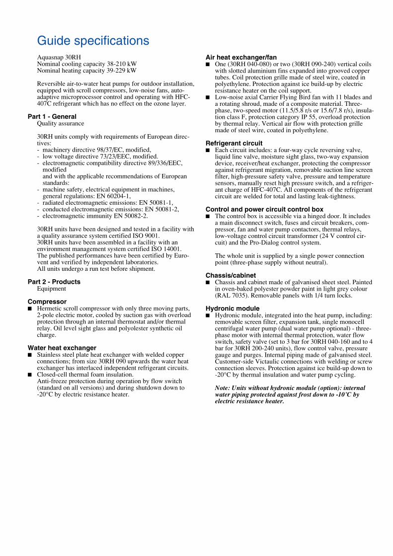
Guide specificationsAquasnap 30RHNominal cooling capacity 38-210 kWNominal heating capacity 39-229 kW
Reversible air-to-water heat pumps for outdoor installation, equipped with scroll compressors, low-noise fans, auto-adaptive microprocessor control and operating with HFC-407C refrigerant which has no effect on the ozone layer.
Part 1 - General Quality assurance
30RH units comply with requirements of European direc-tives:- machinery directive 98/37/EC, modified,- low voltage directive 73/23/EEC, modified.- electromagnetic compatibility directive 89/336/EEC,
modified and with the applicable recommendations of European standards:
- machine safety, electrical equipment in machines, general regulations: EN 60204-1,
- radiated electromagnetic emissions: EN 50081-1,- conducted electromagnetic emissions: EN 50081-2,- electromagnetic immunity EN 50082-2.
30RH units have been designed and tested in a facility with a quality assurance system certified ISO 9001.30RH units have been assembled in a facility with an environment management system certified ISO 14001.The published performances have been certified by Euro-vent and verified by independent laboratories.All units undergo a run test before shipment.
Part 2 - ProductsEquipment
Compressor� Hermetic scroll compressor with only three moving parts,
2-pole electric motor, cooled by suction gas with overload protection through an internal thermostat and/or thermal relay. Oil level sight glass and polyolester synthetic oil charge.
Water heat exchanger� Stainless steel plate heat exchanger with welded copper
connections; from size 30RH 090 upwards the water heat exchanger has interlaced independent refrigerant circuits.
� Closed-cell thermal foam insulation.Anti-freeze protection during operation by flow switch (standard on all versions) and during shutdown down to-20°C by electric resistance heater.
Air heat exchanger/fan� One (30RH 040-080) or two (30RH 090-240) vertical coils
with slotted aluminium fins expanded into grooved copper tubes. Coil protection grille made of steel wire, coated in polyethylene. Protection against ice build-up by electric resistance heater on the coil support.
� Low-noise axial Carrier Flying Bird fan with 11 blades and a rotating shroud, made of a composite material. Three-phase, two-speed motor (11.5/5.8 r/s or 15.6/7.8 r/s), insula-tion class F, protection category IP 55, overload protection by thermal relay. Vertical air flow with protection grille made of steel wire, coated in polyethylene.
Refrigerant circuit� Each circuit includes: a four-way cycle reversing valve,
liquid line valve, moisture sight glass, two-way expansion device, receiver/heat exchanger, protecting the compressor against refrigerant migration, removable suction line screen filter, high-pressure safety valve, pressure and temperature sensors, manually reset high pressure switch, and a refriger-ant charge of HFC-407C. All components of the refrigerant circuit are welded for total and lasting leak-tightness.
Control and power circuit control box� The control box is accessible via a hinged door. It includes
a main disconnect switch, fuses and circuit breakers, com-pressor, fan and water pump contactors, thermal relays, low-voltage control circuit transformer (24 V control cir-cuit) and the Pro-Dialog control system.
The whole unit is supplied by a single power connection point (three-phase supply without neutral).
Chassis/cabinet� Chassis and cabinet made of galvanised sheet steel. Painted
in oven-baked polyester powder paint in light grey colour (RAL 7035). Removable panels with 1/4 turn locks.
Hydronic module� Hydronic module, integrated into the heat pump, including:
removable screen filter, expansion tank, single monocell centrifugal water pump (dual water pump optional) - three-phase motor with internal thermal protection, water flow switch, safety valve (set to 3 bar for 30RH 040-160 and to 4 bar for 30RH 200-240 units), flow control valve, pressure gauge and purges. Internal piping made of galvanised steel. Customer-side Victaulic connections with welding or screw connection sleeves. Protection against ice build-up down to -20°C by thermal insulation and water pump cycling.
Note: Units without hydronic module (option): internal water piping protected against frost down to -10˚C by electric resistance heater.

Carrier Pro-Dialog Plus control systemPro-Dialog Plus ensures the following functions:
Control� Entering and leaving water temperature control by PID loop
with compressor run time equalising. The system perma-nently adjusts the system inertia and ensures complete pre-vention of excessive compressor cycling. The heat pump can safely operate with a low system water volume which often makes the use of a buffer tank unnecessary (see mini-mum water volume in this document).
� Head pressure control by auto-adaptive algorithm (fan speed).
� Water pump control (optional dual pump with automatic change-over).
� Defrost cycle control with auto-adaptation of the parame-ters.
� Control at the second set point (example: unoccupied room).
� Set point reset as a function of the air temperature or the difference between entering/leaving water temperature.
� Automatic change-over of heating/cooling, as a function of the outdoor temperature with adjustable dead band.
� Optional control module with a relay for the control of sup-plementary electric resistance heaters. Four stages maxi-mum, with start-up of the last stage in case of a heat pump shutdown as a result of a fault condition.
Safety� The system checks the evolution of the parameters: tempe-
ratures, pressures ... and responds to maintain the compres-sor within the operating range. If despite this one parame-ter exceeds its limit, an alert message is generated or the unit is shut down. The following faults cause the refrige-rant circuit or the unit to be shut down:- Low suction pressure- High discharge pressure- Low suction temperature- Low water entering temperature in heating mode- Compressor, water pump overload- Reverse compressor rotation- Temperature sensor and pressure transducer fault- Board and loss of communication fault- Customer safety device tripping- Heat exchanger anti-freeze protection- More than 50 alert or fault codes to facilitate fault detec-
tion
Operator interface� Includes status or fault LEDs, two numerical displays, a
refrigerant system synoptic diagram and a command key-board.
� Immediate display of parameters: entering/leaving water and ambient air temperatures, compressor suction/dis-charge pressures and temperatures, set point, operating temperatures and number of compressor start-ups.
� Diagnosis and complete parameter set by selection of one of the following menus: information, temperatures, pres-sures, set points, input values, test, configuration, alarms, alarm history and operating log.
Remote management of the heat pump� Volt-free contact inputs permit:
- Start/stop control- Selection of cooling or heating mode- Integration of a customer safety device- Operation at the second set point* (example room un-
occupied)- Maximum demand limit* (three limit levels from size
30RH 090 onwards)* One or the other for 30RH 040-080
� Outputs are available for:- Start-up of a boiler relay (shutdown of the heat pump
below a minimum outdoor temperature)- Signalling of a fault condition for each circuit.
� The internal clock permits programming of the following operations:- heat pump start/stop- control at the second set point (e.g. unoccupied room)- fan at low speed to reduce the noise level (e.g. during the
night)� Master/slave control of two heat pumps operating in
parallel with operating time equalisation.� RS 485 serial port for remote heat pump control via
communications bus.

Manufactured by Carrier SA, Montluel, France.Order No. 13422-20, 09.2003. Supersedes: 13422-20, 11 2001. Printed on Totally Chlorine Free Paper.Manufacturer reserves the right to change any product specifications without notice. Printed in the Netherlands.The cover photo is solely for illustration purposes, and is not contractually binding.