304101 manual, 375 jd 4045 rev 1 - home - boss …bossair.com/manuals/375jd4045(rev1).pdf · ·...
TRANSCRIPT
1
375 DP JD04
OPERATORS, MATENTANCE, AND PARTS MANUAL
SERIAL NUMBER_________________________________ MODEL NUMBER_________________________________
304101 REV 1
05-03-16

2
TABLE OF CONTENTS INTRODUCTION 3 SECTION 1 SAFETY 5 1.1 TOWING 5 1.2 PARKING 7 1.3 BEFORE START-UP 8 1.4 COMPRESSOR USE AND AIR 8 1.5 SERVICING 9 1.6 LIFTING 9 SECTION 2 DESCRIPTION 10 2.1 INTRODUCTION 10 2.2 ROTARY COMPRESSOR COMPONENTS 10 2.3 DIESEL ENGINE COMPONENTS 12 2.4 CHASSIS 12 2.5 ENCLOSURE 13 2.6 INSTUMENT PANEL DOOR 13 SECTION 3 OPERATION 14 3.1 START UP PREPARATION 14 3.2 STARTING PROCEDURE 14 3.3 EMERGENCY SHUTDOWN 14 3.4 ROUTINE SHUTDOWN 14 SECTION 4 MAINTENANCE 15 4.1 WHEEL BEARINGS 15 4.2 SAFETY CHAINS 16 4.3 ENGINE FUEL SPECS 17 4.4 ENGINE OIL AND FILTER 18 4.5 ENGINE COOLING SPECS 18 4.6 FAN 19 4.7 RADIATOR PRESSURE CAP 20 4.8 RADIATOR 20 4.9 COMPRESSOR OIL 20 4.10 COMPRESSOR ENGINE AND OIL FILTER MAITENANCE 23 4.11 COMPRESSOR OIL THERMOSTATIC VALVE 25 4.12 COMPRESSOR AIR/OIL SEPERATOR 25 4.13 BELTS & BELT ADJUSTMENT 26 4.14 CONTROL- OPERATION ADJUSTMENTS 26 4.15 INSTRUMENTS 28 4.16 BATTERY 29 4.17 MAINTENANCE SCHEDULE 29 4.18 DAILY OPERATION 29 4.19 MAINTENANCE SCHEDULE CHART 31 4.20 RECOMMENDED SPARE PARTS 32 4.21 PROCEDURE FOR ORDERING PARTS 32 SECTION 5 TROUBLESHOOTING 33
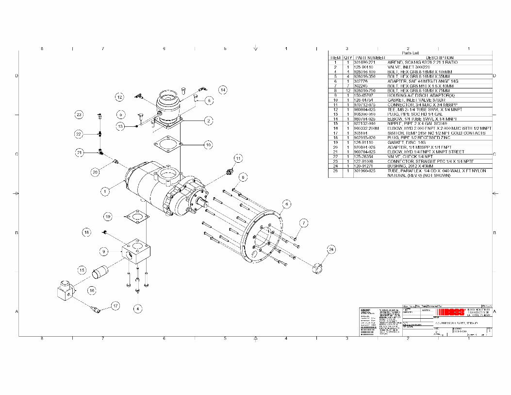
WARRANTY 41 SECTION 6 ASSEMBLY DRAWINGS
3
OWNER’S RESPONSIBILITY
Your new Smith Air Compressor was engineered, built and tested to ensure the user both dependable and economical service. This compressor has also been certified as conforming to the applicable Noise Emission standards of the Environmental Protection Agency. Continuation of the performance built into this unit depends upon the care it received in use. Therefore, operation and maintenance procedures described in this manual should be followed carefully. The operator and service personnel responsible for the care of this unit should be thoroughly familiar with this information. It is the owner’s and/or operator’s responsibility to perform all safety checks and to ensure that all lubrication, maintenance instruction and recommended practices are followed for safe operation. If disassembly or replacement is required, particularly of internal parts, we recommend the owner see his dealer and not attempt the repair himself. It is owner’s responsibility to ensure that the preventive maintenance program is followed at the recommended intervals. Proper care and service will assure long service life with a minimum of problems and operating expenses. We recommend that the owner and operator be thoroughly familiar with the contents of the manual. If you encounter difficulties which you cannot diagnose our service personnel are prepared to help you. Our toll free number is 1-800-635-6587. Out side the continental United States and Canada our number is 219-324-7776. The model and serial number information is requested on all correspondence. This information can be found on the Model Number Identification Plate. The information contained on the identification plate should be transferred to the cover page of the manual for future reference.
4
WARNING
ALL UNITS ARE SHIPPED WITH A DETAILED OPERATORS AND PARTS MANUAL. THIS MANUAL CONTAINS VITAL INFORMATION FOR THE SAFE USE AND EFFICIENT OPERATION OF THIS UNIT. CAREFULLY
READ THE OPERATORS MANUAL BEFORE STARTING THE UNIT. FAILURE TO ADHERE TO THE INSTRUCTIONS COULD RESULT IN
SERIOUS BODILY INJURY OR PROPERTY DAMAGE.
AIR COMPRESSOR SAFETY PRECAUTIONS
Safety is basically common sense. There are standard safety rules but each situation has its own peculiarities, which cannot always be covered by rules. Therefore with your experience and common sense, you are in a position to do something about safety. Lack of attention to safety can result in: accidents, personal injury, reduction of efficiency and worst of all - Loss of Life. Watch for safety hazards. Correct them promptly. Use the following safety precautions as a general guide to safe operation: Do not attempt to remove any compressor parts without first relieving the entire system of pressure. Do not attempt to service any part while machine is operating.
DANGER
CHECK THE COMPRESSOR SUMP OIL LEVEL ONLY WHEN THE COMPRESSOR IS NOT OPERATING AND SYSTEM IS COMPLETELY
RELIEVED OF PRESSURE. OPEN SERVICE VALVE TO INSURE RELIEF OF SYSTEM AIR PRESSURE WHEN PERFORMING MAINTENANCE ON
COMPRESSOR AIR/OIL SYSTEM. FAILURE TO COMPLY WITH THIS WARNING MAY CAUSE DAMAGE TO PROPERTY AND SERIOUS BODILY
HARM.
Do not operate the compressor at pressure or speed in excess of its rating as indicated in “Compressor Specifications”. Periodically check all safety devices for proper operation. Do not play with compressed air. Pressurized air can cause serious injury to personnel. Exercise cleanliness during maintenance and when making repairs. Keep dirt away from parts by covering parts and exposed openings.
5
USER MODIFICATION
This Smith Air Compressor incorporates numerous features to minimize noise emissions from the unit during operation. This configuration has been tested for noise emissions at conditions specified by the U.S. Environmental Protection Agency. Conformance to regulations requires the incorporation of the following notification and definition in the OPERATION AND MAINTENANCE MANUAL.
TAMPERING WITH NOISE CONTROL SYSTEM PROHIBITED
Federal law prohibits the following act: 1. The removal, rendering inoperative, other than for purposes of
maintenance, repair or replacement of any device or element of design incorporated into any new compressor for the purpose for noise control prior to its sale or delivery to the ultimate purchaser.
2. The use of the compressor after such device or element of design has been removed or rendered inoperative by any person. Among the acts included in the prohibition against tampering are those listed: 1. Removal or rendering inoperative any of the following:
a. The engine exhaust system including the manifold, muffler or tailpipe. b. Any of the enclosure components and associated sound barrier
materials. c. The sound baffles in the intake, exhaust and cooling system gas paths. d. The air intake system including the air cleaner, the intake ducting,
valve cover and gaskets. 2. Removal of any of the following:
a. Engine mounts or other sound isolating barriers in the system. b. Fan shrouding and sound hood.
3. Operation of the compressor with any of the enclosure doors open.
6
SECTION 1
SAFETY
1.1 TOWING OVERVIEW • The hitch to coupler is a pinch point. Keep hands and fingers clear • Check towbar connections • Secure safety chains-couple curbside chain shorter • Replacement tires should be of the same size and rating as the original
equipment. Wheel lug bolts or wheel-bearing nuts must be tightened to a specific torque.
• Raise third wheel or stand • Don’t exceed speed limit • Remember your vehicle is longer than usual with compressor attached • Never tow trailers unless all electrical lights and brakes are connected
and working properly (if so equipped). PREPARING TO TOW 1. Carefully inspect the air compressor ball hitch or pintle, drawbar and
chains, look for excessive wear, corrosion, crack, ben, dented or otherwise deformed or degraded member, loose nuts, bolts or other fasteners. Do the same on the towing vehicle’s hitch and related hardware. If inspection shows any worn or damaged parts DO NOT TOW the compressor until repairs are made.
TORQUE SPECIFICATIONS
HITCH FASTERNER 150 FT/LBS WHEEL LUG FASTENERS 65/70 FT/LBS SAFETY CHAIN FASTENERS 50 FT/LBS
2. Choke or block the compressor wheels and raise the drawbar of the
compressor to the approximate level of the towing vehicle hitch. 3. Back the towing vehicle to the compressor and lower the compressor on the hitch. 4. Engage, close and lock the coupling device. 5. Attach safety chains, a couple of curbside chains as well, they may be
shorter than the other chains.

7
6. Attach electrical and brake connections to connections on the tow
vehicle, when so equipped. 7. Fully retract front screw jack and rear stabilizer legs if unit is so
equipped. Place any retractable stand in a full up and locked position with the stand horizontal.
8. Carefully inspect the tires and check the tire pressure. 9. Test all running, tail, stop and directional lights. Make sure that all
lights, reflectors and reflecting surfaces are clean and in good condition. 10. Disconnect and store service air hoses and tools in the tow vehicle. 11. Close and latch the hood and any access panels. 12. Set the parking brake in the towing vehicle. Only then release any
compressor brake and remove chocks and blocks from compressor wheels.
13. Test running brake operation, if so equipped, including any breakaway switch.
TOWING 1. Never exceed 55 miles per hour (88 kilometer per hour) 2. Adjust speed to reflect weather and road conditions. 1.2 PARKING CHOOSING A PARKING SITE 1. Park the compressor on a level firm area. Never park on a grade of
more than 15 degrees (27%). If you must park on any grade, park across the grade so that the compressor does not tend to roll.
2. Park so that the wind carries exhaust fumes and radiator heat away from the compressor inlet.
3. Park away from work site dust. 4. Stay clear of electrical power lines. Keep the towing vehicle or
equipment carrier, compressor, hoses, tools and all personnel at least 10 feet from power lines and buried cables.
PARKING PROCEDURES 1. Chock or block the wheels and set the compressor brake, if so
equipped. 2. Disconnect the brake and electrical connections, if so equipped. 3. Disconnect the safety chains and wrap them around or hook. 4. Lower any front jack or stabilizer legs, if so equipped.
8
5. Lower and lock any caster wheel. 6. Unhitch the compressor from towing vehicle. 7. Move the towing vehicle clear of the compressor 8. Immediately erect hazard indicators, barricades and if working at night,
light flares to keep others clear of the compressor. 1.3 BEFORE STARTING THE COMPRESSOR 1. Check fluids levels and for possible leaks. 2. Use adequate hose and couplings with safety locks or pins. 3. Remove all tools and/or loose items from engine compartment. 4. Relieve any pressure in receiver tank. 5. Use proper eye and ear protection. 1.4 COMPRESSOR USE AND COMPRESSED AIR 1. Air from this machine is not fir for human consumption-do not use air
for breathing or food processing. 2. Never operate in an enclosed area. 3. Never use compressed air to clean your clothes and never direct it at
another person, it can kill. 4. Always wear eye protection. 5. Install check valve (“OSHA”) upstream of hose to prevent hose whip in
case of a rupture. 6. Keep doors or hoods closed on machines in operation. 7. Do not touch hot surfaces or moving parts, such as exhaust or fans. 8. Do not adjust or restrict relief valves. 9. Do not refuel while machine is running; shut down and allow to cool
before refueling. 10. Do not jump-start with cable connections directly on battery. 11. To prevent back strain, only the smallest air compressors should be
unhitched by hand. Drawbars on all other units must be raised and lowered by a jack, chain fall or other lifting device.
12. Do not use air at pressure higher than 30 PSIG (207 KPA) for cleaning purposes. Use of higher air pressure can cause injury to the operator.
13. Keep compressor hoods closed except when making repairs or adjustments or servicing the compressor.
14. Make sure all personnel are out of and clear of the compressor before starting or operating it.
15. Do not use ether cylinders or air line antifreeze compound in confined area.
9
1.5 SERVICING 1. Before servicing compressor, relieve receiver pressure and allow to
cool. 2. Be sure all opened doors and hoods are propped and secured. 3. Disconnect battery before any work is to be performed. 4. Wipe up all spills resulting from servicing. 5. Disconnect the grounded (negative) battery connection before making
repairs or cleaning inside the enclosure. 6. Do not use flammable solvents for cleaning the compressor. 7. Do not remove radiator cap quickly, it may cause spray of scalding
coolant and severe burns to operator. 8. Make repairs only in clean, dry and well-lighted and well-ventilated
areas. 9. Keep all parts of the body and any hand held tools or other metal
objects away from exposed live parts of the electrical system. 10. Replace damaged fuel tanks or lines immediately. DO NOT WELD
on or near fuel tanks or lines. 11.Make sure all personnel are out of the compressor before closing and latching hoods. 12. Radiator coolant is under pressure. When checking coolant in radiator, loosen cap slowly first, to relieve pressure before removing cap completely.
1.6 LIFTING 1. If the compressor is provided with a lifting bail, then lift by the bail. If no bail is provided, then lift by sling. 2. When lifting by helicopter, use a sling. Do not lift by unit lifting bail. 3. Inspect the entire lifting, rigging and supporting structure to ensure it is in good condition and has a rated capacity of at least the gross weight of the compressor plus 50%.
10
SECTION 2 DESCRIPTION
2.1 INTRODUCTION Your Smith Air Compressor portable is a gas/diesel driven Rotary Screw Compressor unit that provides superior performance and reliability along with a minimal amount of required maintenance. 2.2 ROTARY COMPRESSOR COMPONENTS COMPRESSOR DESCRIPTION The compressor assembly is a positive displacement, oil flood lubricated, screw type unit employing one stage of compression to achieve the desired pressure. Components include a housing (stator), two screws (rotors), gears, bearings and bearing supports. In operation, two helical grooved rotors mesh to compress air. Inlet air entering the casing is compressed at the male lobes roll down the female grooves, pushing trapped atmospheric air along and compressing it in one stage of compression. This process delivers smooth-flowing air at full pressure to the receiver. To illustrate the compression sequence, consider the action of the male lobe as similar to a ball. As a helix rotates, the ball (male lobe) meshes with the groove to start a compression cycle with trapped atmospheric air. As the ball moves down the groove, air is compressed. Atmospheric air fills in behind the ball preparing the groove for another compression cycle as rotation continues and the male lobe again meshes with the groove. During the compression cycle, oil is injected into the compressor for the purpose of lubrication, cooling and sealing. Compressed air laden with oil leaves the compressor unit through a discharge port, which is designed to give optimum performance within the desired discharge pressure range.

11
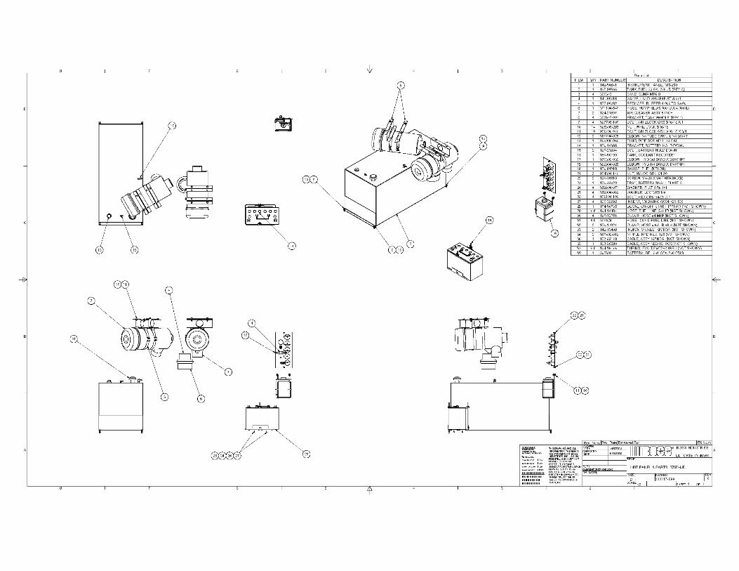
AIR FILTER The Rotary Screw Compressor unit and engine are protected by a high efficiency, two-stage air filtering system. This is a dry filter that requires maintenance when the air filter restriction gauge says it is time. OIL COOLING The compressor is an “oil flooded” compressor. The oil lubricates, seals and cools the internals of the compressors as it is injected into the compressor. The oil goes through the compressor with the air where it picks up the heat generated by the compression process then seals the spaces between moving parts and lubricates bearings. The hot oil must be cooled. It is separated from the air, passed through the oil cooler (mounted next to the engine radiator), through a thermostatic valve (that helps to rapidly warm cold oil at start-up), then through a full flow oil filter and then back into the compressor. See instructions 4.10 and 4.13 for oil filter element and air/oil separating element servicing. AIR/OIL SEPARATOR At the compressor discharge the compressed air and the hot oil flow into a steel ASME coded pressure vessel (rated at 175 psig-250psig) that acts as a reservoir for the air and separates out the oil. From the bottom of this oil sump the oil leaves the vessel on its way to the oil cooler. The air and the slight oil mist still entrained in the airflow through the separator element, which removes the last of the oil from the air. The air passes on out to its final use and the separated oil goes through the scavenge line to the compressor intake to re-enter the system. As the compressor air leaves the receiver it goes through a minimum pressure valve that is set to maintain at least 80 psig (55kpa) in the receiver when the compressor is running. The purpose of this pressure is to insure that there is pressure to force the oil out of the bottom of the receiver, through the oil cooling system so that sufficient oil is injected into the compressor. CONTROL SYSTEM The Smith Air Compressor portable is simple to operate. Starting procedure is explained in section 3 and on the instrument panel door of the compressor. Each machine has an On/Off switch and a safety bypass switch that bypasses the safety shutdowns. Once the machine is “on line” and in the run position, control is automatic. The control system is
12
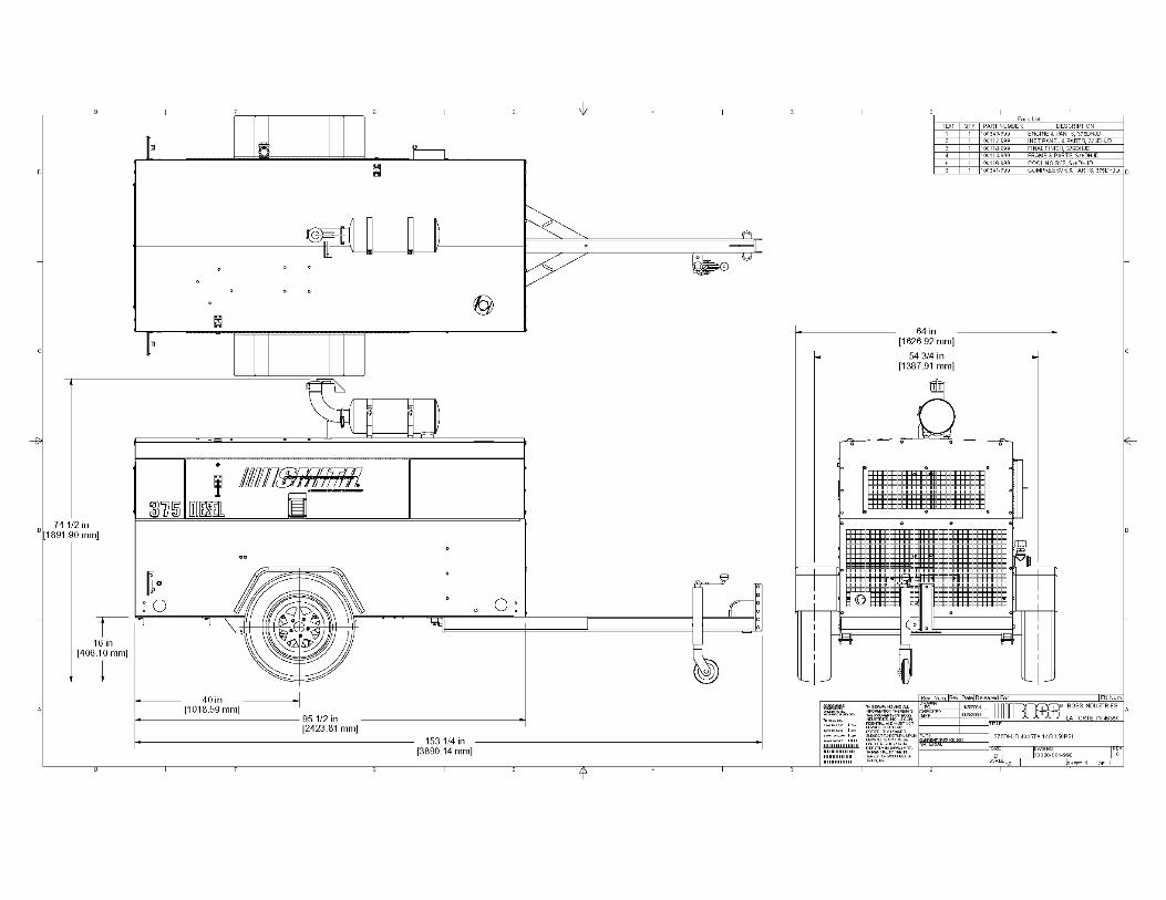
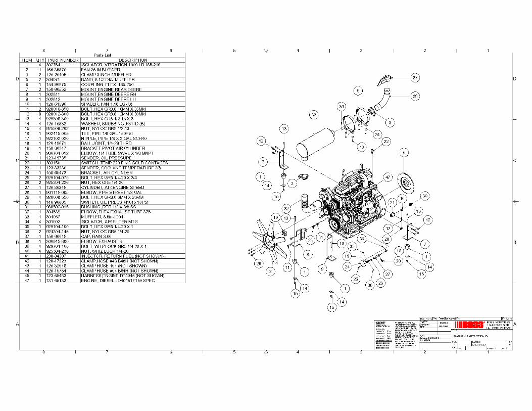
automatic. The control system senses the need for air and adjusts the speed of the engine and compressor as well as the opening of the compressor inlet valve to supply the amount of air needed. If the air demand is zero, the engine and compressor “idle” and the inlet valve is shut to control the air entering the compressor. If the demand is maximum, the opposite happens, full speed and wide-open inlet valve. Intermediate air demands give intermediate speeds and valve openings for maximum operating efficiency. Service and adjustments are in section 4.14. 2.3 ENGINE COMPONENTS ENGINE DESCRIPTION The engine in each Smith Air Compressor portable compressor is selected to have reserve horsepower and speed necessary to drive the compressor and all accessories when operating up to a discharge pressure 100 psig (686kpa) to 220 psig (1509kpa). RADIATOR The radiator is selected to handle the heat load of the engine. Mounted next to the compressor oil cooler. Cooling air is moved through these two coolers with a specially selected engine fan. The system is designed to handle extreme heat conditions. FUEL SYSTEM All units are supplied with fuel tank capacity adequate for a day’s normal operation, fuel filtering system and optional low fuel shutdown. See section 4.3 for fuel servicing. MUFFLER Engine noise is reduced by a durable, low restriction engine muffler. 2.4 CHASSIS FRAME The entire compressor frame and body is “utilized” and constructed of 3/16” or 10 gauge steel plate, resulting in light weight while providing a much stronger body than conventional designs of light sheet metal over structural members.
13
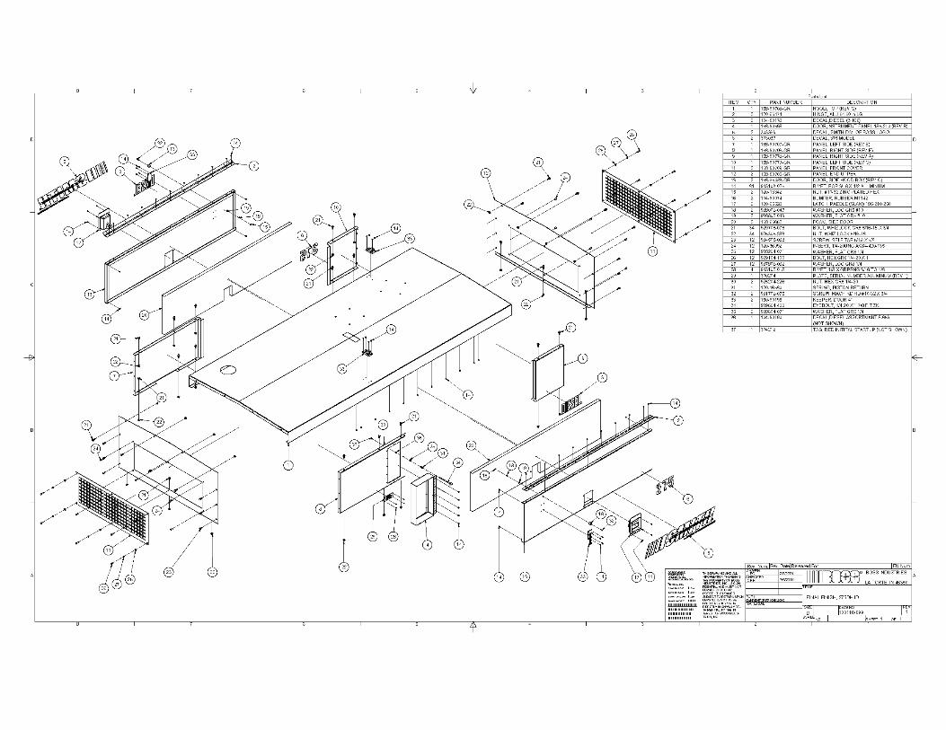
TOWBAR AND HITCH At the end of a rugged steel drawbar there is either a ball hitch, a pintle hitch or a combined ball/pintle hitch-selection is made at time of purchase. (Adjustable height optional) RUNNING GEAR Axle, wheels and tires are all sized for their job. This unit is equipped with a single axle. The lightweight design of the compressor plus the axle design make towing at highway speed possible. 2.5 ENCLOSURE Enclosure is 14 gauge metal with powder coat finish. Each access panel has lockable handles with mechanical props. 2.6 INSTRUMENT PANEL DOOR Lockable instrument panel doors provide access to all controls and gauges.
14
SECTION 3 OPERATION
3.1 START UP PREPARATION 1. Check engine and compressor oil levels. Do not overfill 2. Check coolant level in radiator. (Fill at coolant recovery bottle). 3. Check for fuel, oil and coolant leaks 4. Check air cleaner, clamps and hoses 5. Check battery connections 6. Check and adjust tension of fan belts. 7. NOTE: This unit has minimum air pressure valve to assure compressor
oil flow. There will be no airflow from the compressor if receiver pressure is less that 80 PSIG.
3.2 STARTING PROCEDURE 1. Close service valves and move unloader valve to “START” position 2. Press and hold bypass button and turn starter switch to “START”
position. If engine fails to start. DO NOT attempt to restart until cranking motor stops rotating. Before restarting, starter switch must be returned to “OFF” position
3. When engine starts, release starter switch and hold bypass button down until oil pressure reaches 15PSI then release. Maintain unloader valve at “START” position until engine is warm and operating smoothly, then move unloader valve to “RUN” position.
3.3 EMERGENCY SHUTDOWN PROCEDURE
Turn start stop switch to “OFF” position 3.4 ROUTINE SHUTDOWN PRODEDURE 1. Move unloader to start position 2. Allow compressor to run 2 to 3 minutes to cool 3. Move on/off switch to “OFF” position
15
SECTION 4 MAINTENANCE
4.1 WHEEL BEARINGS Wheel bearings leave the factory properly packed and adjusted and under normal circumstances should require inspection every six months or so, depending upon use. INSPECTION Clean exterior of wheel bearing cap before removal. Remove cap and check bearing for damage, adequate grease, cleanliness, rust and end play. End play should be between .001 and .012 (.025 to .03 mm). Correct defective bearings and replace damaged bearings. GREASE THE BEARINGS 1. Remove the rubber plug from the end of the grease cap. 2. Place a standard grease gun onto the grease zerk located in the end of
the spindle. Make sure the grease gun nozzle is fully engaged in the fitting.
3. Pump grease into the zerk. The old, displaced grease will begin to flow back out the cap around the grease gun nozzle.
4. When the new, clean grease is observed, remove the grease gun, wipe off any excess and replace the rubber plug in the cap.
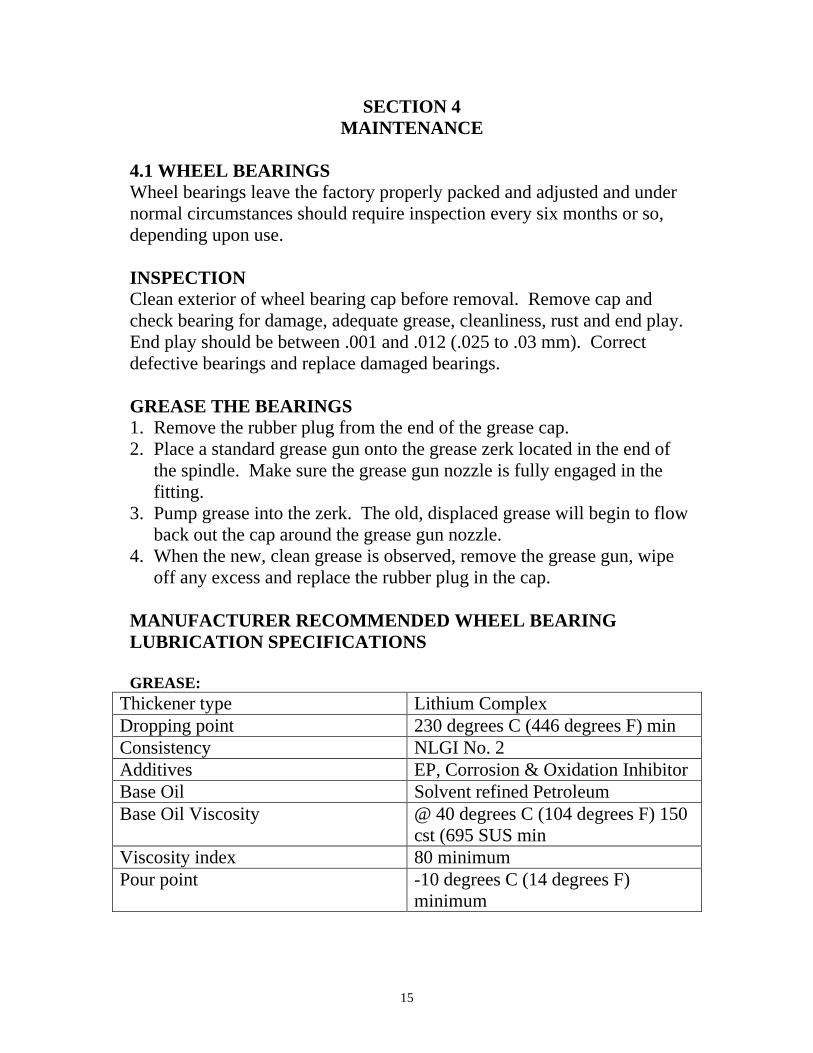
MANUFACTURER RECOMMENDED WHEEL BEARING LUBRICATION SPECIFICATIONS GREASE:
Thickener type Lithium Complex Dropping point 230 degrees C (446 degrees F) min Consistency NLGI No. 2 Additives EP, Corrosion & Oxidation Inhibitor Base Oil Solvent refined Petroleum Base Oil Viscosity @ 40 degrees C (104 degrees F) 150
cst (695 SUS min Viscosity index 80 minimum Pour point -10 degrees C (14 degrees F)
minimum
16
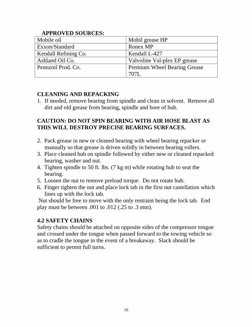
APPROVED SOURCES: Mobile oil Mobil grease HP Exxon/Standard Ronex MP Kendall Refining Co. Kendall L-427 Ashland Oil Co. Valvoline Val-plex EP grease Pennzoil Prod. Co. Premium Wheel Bearing Grease
707L CLEANING AND REPACKING 1. If needed, remove bearing from spindle and clean in solvent. Remove all
dirt and old grease from bearing, spindle and bore of hub. CAUTION: DO NOT SPIN BEARING WITH AIR HOSE BLAST AS THIS WILL DESTROY PRECISE BEARING SURFACES. 2. Pack grease in new or cleaned bearing with wheel bearing repacker or
manually so that grease is driven solidly in between bearing rollers. 3. Place cleaned hub on spindle followed by either new or cleaned repacked
bearing, washer and nut. 4. Tighten spindle to 50 ft. lbs. (7 kg m) while rotating hub to seat the
bearing. 5. Loosen the nut to remove preload torque. Do not rotate hub. 6. Finger tighten the nut and place lock tab in the first nut castellation which
lines up with the lock tab. Nut should be free to move with the only restraint being the lock tab. End play must be between .001 to .012 (.25 to .3 mm). 4.2 SAFETY CHAINS Safety chains should be attached on opposite sides of the compressor tongue and crossed under the tongue when passed forward to the towing vehicle so as to cradle the tongue in the event of a breakaway. Slack should be sufficient to permit full turns.

17
4.3 ENGINE FUEL SPECIFICATIONS WARNING: DO NOT MIX GASOLINE OR ALCOHOL WITH DIESEL FUEL. THIS MIXTURE CAN CAUSE AN EXPLOSION. CAUTION: DUE TO THE PRECISE TOLERANCES OF DIESEL INJECTION SYSTEMS, IT IS EXTREMELY IMPROTANT THAT THE FUEL BE KEPT CLEAN AND FREE OF DIRT OR WATER. DIRT OR WATER IN THE SYSTEM CAN CAUSE SEVERE DAMAGE TO BOTH THE INJECTION PUMP AND THE INJECTION NOZZLE. USE ASTM NO.2 D FUEL WITH A MINIMUM CETANE NUMBER OF 40. NO.2 DIESEL. FUEL GIVES THE BEST ECONOMY AND PERFORMANCE UNDER MOST OPERATING CONDITIONS. SEE ENGINE MANUFACTURES OPERATORS/INSTRUCTION MANUAL FOR THE PROPER ENGINE FUEL FOR THE BRAND ENGINE IN YOUR SMITH AIR COMPRESSOR.
HIGH ALTITIDE AND LOW TEMPERATURE FUELS Fuels with cetane numbers higher than 40 may be needed in high altitudes or extremely low ambient temperatures to prevent misfires and excessive smoke.
COLD WEATHER FUEL At opening temperatures below 8 degrees C (32 degrees F) use a blend of No.1D and No.2D fuels, also know as “winterized” No.2D. NOTE: No.1D fuel can be used; however, fuel economy will suffer.
Use low sulfur content fuel having a cloud point that is at least 10 degrees below the lower expected fuel temperature. Cloud point is the temperature at which wax crystals begin to form in diesel fuel.
The viscosity of the fuel must be kept above 1.3 centistokes to provide adequate fuel system lubrication.
ENGINE FUEL FILTER See engine manufactures operator/instruction manual for the proper fuel filter replacement changing intervals for the brand engine in your SMITH compressor.
18
WARNING: KEEP HANDS AND FINGERS CLEAR OF FITTING. HIGH PRESSURE OF THE FUEL CAN CAUSE PENETRATION OF THE SKIN. SEEK IMMDIATE MEDICAL ATTENTION IF SKIN IS BROKEN BY THE FUEL SPRAY.
4.4 ENGINE OIL AND FILTER See engine manufactures operator/instruction manual for the proper engine oil and filter changing intervals for the brand engine in your SMITH compressor.
OIL FILTER REPLACEMENT
1. Clean the area around the lubricating filter head. 2. Remove the filter. 3. Clean the gasket surface of the filter head.
NOTE: The o-ring can stick on the filter head. Make sure it is removed. 4. Apply a light film of lubricating oil to the gasket-sealing surface before
installing. 5. Install the filter as specified by the filter manufacturer. CAUTION: MECHANICAL OVER-TIGHTENING MAY DISTORT THE TREADS OR DAMAGE THE FILTER ELEMENT SEAL.
4.5 ENGINE COOLING SPECIFICATIONS: Diesel engines require a balanced coolant mixture of water and ethylene glycol base antifreeze. This protects the engine cooling system from corrosions as well as freezing damage. The Smith Air Compressor portables are shipped form the factory with a 50/50 mixture of water and ethylene glycol. In tropical climates where freeze protection is not required, glycol engine coolant should still be used. It will help prevent corrosion and pitting of cylinder liners. See engine manufactures operator/instruction manual for the proper engine coolant for the brand engine in your SMITH compressor.
19
MIXTURES: Antifreeze concentration level should not exceed recommended levels. To do so can cause cooling system failure.
• Use a high quality, low silicate antifreeze • A mixture of 50% antifreeze and 50% water is required for temperatures
above –37 º C (-34 ºF). • A mixture of 60% antifreeze and 40% water us required for
environments below –37 ºC (-34 ºF). This provides protection to –54 ºC (-65 ºF).
• Never exceed a 60% antifreeze and 40% water mix.
ENGINE COOLING SYSTEM All engines have a pressurized cooling system that contains a 50/50 mixture of water and ethylene glycol. Daily maintenance of the system includes a check of the coolant level, proper belt adjustment of fan and water pump drives, soundness of fan and cleanliness of the radiator and oil cooler to permit airflow. Further cooling system maintenance is defined in the engine maintenance manual. COOLANT LEVEL Before each start-up, when radiator is cold, the coolant should be checked. When needed, refill with a 50/50 solution of water and ethylene glycol, DO NOT use 100% antifreeze for “topping off”. WARNING: CHECK THE COOLANT LEVEL ONLY WHEN THE ENGINE IS STOPPED AND THE TEMPERATURE IS BELOW 160 º F (70 ºC) FAILURE TO DO SO CAN CAUSE PERSONAL INJURY FROM HEATED COOLANT SPRAY.
4.6 FAN Check the fan for cracks loose rivets and bent or loose blades. Make sure it is securely mounted. Tighten the cap screws if loose. Replace damaged fans.
20
WARNING: NEVER USE THE FAN TO ROTATE THE ENGINE. THE BLADE(S) CAN BE DAMAGED CAUSING A FAN FAILURE, WHICH CAN RESULT IN PERSONAL INJURY OR PROPERTY DAMAGE.
4.7 RADIATOR PRESSURE CAP If coolant continually spills from radiator through the overflow then the radiator cap should be tested and/or replaced with a cap of the same pressure rating, generally 13 PSI. Be sure cap is turned to the proper secure position.
4.8 RADIATOR Any sign of leakage from the radiator may justify a pressure test to assure its soundness. Radiator leaks should only be repaired by qualified service people. Dirt that clogs the cooling fins of the radiator should be removed. The use of an air stream of high-pressure steam cleaner should be done with caution so as to not damage the delicate fins. Bent cooling fins will reduce the cooling capability of the radiator.
4.9 COMPRESSOR OIL The life and proper operation of the compressor is dependent on adequate and clean compressor oil. DEXRON - 111 Automatic Transmission Fluid is supplied with the new machine and should be used for proper level maintenance and for oil changes. We recommend that you use DEXRON - 111 Automatic Transmission Fluid.
WARNING: DO NOT REMOVE CAPS OR OTHER COMPONENTS WHEN COMPRESSOR IS RUNNING OR PRESSURIZED. BEFORE DOING SO STOP COMPRESSOR AND RELIEVE ALL INTERNAL PRESSURE.
21
COMPRESSOR OIL SPECIFICATIONS It is permissible to use oils other than the ATF shown above; such as Hydraulic oil. If they are used then they must have at least the following minimum properties:
• ISO grade 32 • CPS No. 255675 • API Gravity - • Viscosity, Kinematic
cst at 40 degrees C 33.6 cst at 100 degrees C 5.5 • Viscosity saybolt
SUS at 100 degrees F 173 SUS at 210 degrees F 45 • Viscosity index 98 • Pour point deg. C(deg F) -33(-27) • Flash point deg.C(deg.F) 204(399) • Oxidation stability • Hours to 2.0 mg KOH/g
acid no., ASTM D 943 >600 The advantage in using DEXRON - III in the compressor is that it is good lubricant suitable to its application and it is readily available. There are other oils that may be used that have longer life. They are better able to stand the extreme operating conditions. Whether or not to use these oils is a decision that depends upon the operating conditions. Very frequent oil changes are necessary in extremely hot, dirty operating conditions and if the compressor is operating in a remote, difficult-to-reach service location then perhaps it would be better to use the DEXRON - III because of availability and cost. If, however service is convenient and attentive so that the oil can be used for as long as it will provide good protection; then higher quality oils may be used that will extend the life of the compressor. WARNING SMITH AIR COMPRESSORS DOES NOT RECOMMEND MIXING DIFFERENT TYPES OF OILS. WHEN CHANGING TO A DIFFERENT TYPE OIL, CLEAN COOLER, AIR/OIL RECEIVER AND LINES THOROUGHLY.
22
ADDING COMPRESSOR OIL 1. Level the compressor to assure oil level indicator will be accurate. 2. Remove any dirt around fill cap, which is located on or near the air/oil
receiver and then remove the fill cap itself. 3. Inspect the fill cap for damage and cleanliness. Replace if necessary. 4. Proper oil can then be added till the oil level reaches halfway in the sight-
level tube or the “bullseye”. 5. Replace full cap securely-never put cap on without tightening
immediately. 6. Do not over fill the sump tank. This will cause oil to spray out of the
blowdown valve and/or service valve. CAUTION: DO NOT REPLACE FILL CAP WITH A PIPE CAP; SERIOUS INJURY OR DAMAGE COULD RESULT. THE THREADS ARE DIFFERENT. ALWAYS INSURE A STRAIGHT THREAD FILL CAP IS USED. CHANGING COMPRESSOR OIL 1. Oil and air filter will help prolong oil life. If the oil appears dirty or it has a foul smell it should be replaced. 2. Change compressor oil and filter every 500 hours. 3. Remove fill cap and drain oil from the bottom of the air/oil receiver. Oil will drain more quickly and completely if it is warm from operation. 4. Close all drains and replace oil with fresh oil to proper level. Replace fill cap and run the unit briefly to see if more oil needs to be added and to insure there or no leaks. COMPRESSOR OIL FILTER The oil filter in the compressor lubrication system is of the full flow spin-on canister type. Initially the filter should be replaced after the first 50 hours, then every 500 hours or sooner if indicated. A dirty filter can restrict oil flow, causing high oil temperature condition, which will result in a unit shutdown.
23
CAUTION: SUBSTITUTE FILTERS MAY HAVE INADEQUATE WORKING PRESSURE LIMITS, RESULTING IN ELEMENT LEAKAGE OR RUPTURE. REPLACEMENT FILTERS MUST BE THE SAME QUALITY AND TYPES AS THE ORIGINAL SMITH AIR COMPRESSORS FILTER. COMPRESSOR OIL FILTER REPLACEMENT 1. Using a strap wrench, remove the old element and gasket. 2. Clean gasket seating surface. 3. Apply a light film of oil to the new gasket. 4. Hand tighten new element until new gasket is seated in the gasket
groove. 5. Continue tightening element by hand an additional ½ to ¾ turn. 6. Restart machine and check for leaks. CAUTION: MECHANICAL OVER-TIGHTENING MAY DISTORT THE THREADS OR DAMAGE THE FILTER ELELMENT SEAL. 4.10 COMPRESSOR & ENGINE AIR FILTER MAINTENANCE ELEMENT REPLACEMENT 1. Loosen the clamps that secure the dust cup to the body and remove the
cover. 2. Empty the dirt from the dust cup. 3. Remove the element. 4. Clean the canister and dust cap with a damp cloth inside and out. DO NOT blow dirt out with compressor air. 5. At this time clean or replace the element. 6. Replace the element. 7. Reposition the cover and tighten the clamp, INSTALL WITH “TOP” UP. 7. Reset the air filter restriction indicator (if supplied) and the machine will be ready for operation.
24
CAUTION: WHEN CLEANING AN ELEMENT, THE ELEMENT WILL BE DAMAGED IF YOU EXCEED THE RECOMMENDED MAXIMUM PRESSURE FOR COMPRESSED AIR. (30 PSI/200 KPA) CAUTION: DO NOT STRIKE THE ELEMENT AGAINST ANY HARD SURFACES AND POSSIBLY RUPTURE THE ELEMENT. NEVER BLOW DIRT OUT OF THE INTERIOR OF THE FILTER HOUSING. THIS MAY INTRODUCE DUST DOWNSTREAM OF THE FILTER. INSTEAD, USE A CLEAN DAMP CLOTH. DO NOT OIL ELEMENT. AIR FILTER ELEMENT CLEANING The air filter element is cleaned by using compressed air. The maximum amount of times that an element should be cleaned is (2) times; however the element should be used no longer than a period of one(1) year without changing. Prior to cleaning an element, check the element for damage. Damaged elements must be replaced. When cleaning the element with compressed air, never let the air pressure exceed 30 PSIG (200 kpa). Reverse flush the element by, directing the compressed air up and down the pleats in the filter media from the “clean side” of the element. Continue reverse flushing until all dust is removed. Should any oil or greasy dirt remain on the filter surface, the element should then be replaced. ELEMENT INSPECTION: 1. Place a bright light inside the element to inspect for damaged or leak. 2. Inspect all gaskets and gasket contact surfaces of the housing. Should
faulty gaskets be evident, correct the condition immediately. If the clean element is to be stored for later use, it must be stored in a clean container.
3. After the element has been installed, inspect and tighten all air inlet connections prior to resuming operation.
25
4.11 COMPRESSOR OIL THERMOSTATIC VALVE The oil thermostatic valve acts as a thermostatically controlled by-pass valve and allows varying amounts of oil depending upon the temperature, to by-pass cooler during the warm up period. When circulated oil reaches a temperature of 140 º F, the valve closes the by-pass completely and all the oil is circulated though the cooler. The oil cooler by-pass is restricted enough to cause some warm oil to flow through the cooler during the warm-up period, maintaining a higher average compressor oil temperature. This reduces condensation in the oil system and also reduces the possibility of a slug of cold oil from the cooler, causing a momentary high restriction and a temporary reduction in the oil pressure, hence oil flow. CLEANING OIL THERMOSTAT 1. If it becomes necessary to take the thermostat apart and clean it, disassemble at the bolted flange and remove the element. 2. If coated or dirty, clean as necessary. The element and rubber seal ring
should be cleaned only with hot water. 3. Inspect the element for bent or dented parts. 4. Replace any damage part during cleaning and assembling the pipe
openings should be closed with tape or plugs until pipe connections made.
4.12 COMPRESSOR AIR/OIL SEPARATOR WARNING: DO NOT REMOVE CAPS, PLUGS OR OTHER COMPONENTS WHEN COMPRESSOR IS RUNNING OR PRESSURIZED. PERSONAL INJURY WILL RESULT. BEFORE DOING SO, STOP COMPRESSOR AND RELIEVE ALL INTERNAL PRESSURE. The separator element is located in the top of the air-oil receiver/separator tank. Here the oil mist contained in the air is removed prior to the final discharge of air. Air should be taken only from the outlet service valves on the center of the top end of the separator-never directly from the receiver/separator fittings on the side of the tank. When the oil vapor in the discharge air becomes excessive, the separator element may need replacing. This should not be necessary more than once a year under normal operating conditions.
26
SEPARATOR ELEMENT REPLACEMENT 1. The element may be replaced by removing the head from the top of
separator and pulling the element out. Only a factory element should be used as a replacement.
2. The separator element flange must have a gasket on each side to seal the head on one side and the vessel on the other. The staple in each gasket must be left in the gasket, it acts as a static ground. 3. Re-torque the head bolts uniformly to a specification of 220ft-1b.(dry) or 170ft-lb. (wet) when replacing the separator head.
4.13 BELTS & BELT ADJUSTMENT Visually inspect the belts. Replace belts if cracked or frayed. Check engine manual for proper belt tension. 4.14 CONTROLS-OPERATION AND ADJUSTMENTS The compressor system is designed to match air supply and engine performance with the demand. The components of the control system are, the blowdown valve, start-run solenoid, compressor inlet valve, pressure regulator and an engine air cylinder. The start-run valve that is open in the start run position. This allows air to by-pass the pressure regulator and go directly to the compressor inlet valve, closing it and to the engine air cylinder, holding the throttle at idle. When switched to the run position, shutting off the by-pass air. Control air now has to go through the pressure regulator. The pressure regulator is referred to as a positive type and its operation is proportional to system pressure. As pressure increases it opens, allowing air to pressurize the inlet valve and air cylinder. When there is an air demand, the pressure decreases and the regulator starts to close, relieving the pressure in the inlet valve and air cylinder. An orifice in the regulator bleeds the air out of control line between regulator, engine air cylinder and inlet valve supplies a signal proportional to the system pressure the inlet valve will modulate. With no air demand the pressure rises, the signal air from the regulator closes the inlet valve. When an air demand is present or the pressure falls, the air signal is removed allowing the inlet valve to open to match air demand.
27
The blowdown valve has two functions in the system. First it prevents excessive pressure in the start and unload modes by bleeding off the small amount of air being drawn in during idle. Secondly it relieves or blows down the system on shutdown. This valve is not adjustable. ADJUSTMENT When performing control adjustments care must be taken in regard to safety as the compressor must be running. Be aware of moving parts, as well as, hot items, such as fans, belts and exhaust components. IDLE OR UNLOAD SPEED ADJUSTMENT (For 100 PSI System) With the compressor warmed up and all service valves closed, move start-run switch to run position. Air pressure will build to 120 psig. If air pressure is less than 120 psig, adjust regulator up by turning the adjusting screw clockwise. If air pressure is greater than 120 psig, adjust regulator down by turning the adjusting screw counter-clockwise. Check engine speed with a photo tachometer. If idle speed is not as listed in specifications, adjustment will be required. Note: If your unit is rated at a higher pressure add 20psi to the working pressure for unload pressure; ex: 150 PSI working = 170 unload. IDLE SPEED ADJUSTMENT PROCEDURES On the injection pump throttle arm, there are two adjusting screws. The air cylinder connected to the throttle arm, this air cylinder moves throttle to increase and decrease engine speed with air demand. When adjusting idle speed, the air cylinder should be fully extended moving throttle arm towards front of engine. To adjust idle speed, loosen locknut on adjusting screw towards rear of engine. Turning adjustment screw clockwise will increase speed. If proper speed cannot be obtained with the adjustment screws, it may require loosing the locknut on air cylinder shaft and adjusting clevis. By turning clevis onto shaft speed will increase, by turning clevis out, speed will decrease. After proper speed is set, tighten all locknuts. PRESSURE REGULATOR ADJUSTMENT After setting idle speed and compressor is in run position, the pressure regulator adjustment can be checked and adjusted if required.

28
The air cylinder receives an air signal from the pressure regulator. This air cylinder controls engine speed with air demand. To adjust pressure regulator, with compressor in the run position, open service valve slightly to allow air to bleed out. By watching air pressure gauge note when air cylinder starts to retract, this should be approximately 105 psig. If cylinder does not start to retract until at a lower pressure, the regulator is set to low. The regulator has a locknut and adjustment screw. Loosen the locknut and turn adjustment screw clockwise to increase the pressure. Turning screw counter clockwise decreases pressure. After adjustment is complete, tighten locknut. Note: If you unit is rated a higher pressure add 5 PSI to the working pressure; ex: 150 PSI working = 155 retract pressure. RATED SPEED ADJUSTMENT With the compressor in a run position open service valve slowly until pressure gauge is reading 100 PSI (working pressure). Check that air cylinder is fully retracted, moving throttle arm to full speed and check the engine speed. Adjust the speed to within the specifications in the front of this manual. To adjust there are two adjusting screws on throttle arm, the adjusting screw towards rear of engine is the high-speed adjustment. Loosen locknut on adjustment screw by turning screw counter clockwise, speed increases, after setting speed to specifications, tighten locknut, close service valve and allow compressor to unload and return to idle. 4.15 INSTRUMENTS The standard control panel has gauges for air pressure, oil pressure, coolant temperature, ammeter and hourmeter. Also included is an ignition switch, start/run valve and safety bypass switch. The safety bypass switch cuts out the low oil pressure switch to permit starting. The low oil pressure switch is normally opens and closes upon activation. Safety shutdowns are also provided for high compressor oil temperature and high engine coolant temperature. These switches are normally closed and upon activation. If the compressor will not start or shuts down while in operation without an obvious malfunction, each switch can be checked individually by connecting a jumper wire across the terminal posts one switch at a time. The defective switch must be replaced. NOTE: the existing wiring harness must be connected to the safety switches while making the above check.
29
4.16 BATTERY Batteries supplied with Smith Air Compressor are selected to have ample cold cranking amperes for quick starts in inclement weather. Keep them fully charged and if replacement is necessary the replacement must be of equal capacity. WARNING: BATTERY GAS CAN EXPLODE CAUSING ACID BURN TO SKIN AND BLINDNESS. DO NOT OVERCHARGE OR JUMP THE BATTERY INCORRECTLY. 4.17 MAINTENANCE SCHEDULE A good maintenance program is the key to long machine life. Follow a regular schedule of inspection and servicing, based on operating hours. Keep an accurate logbook for maintenance, servicing and operating hours. Use the factory recommended Periodic Maintenance schedule (based on favorable operating conditions) to serve as a guide to get long and efficient machine life. Regular service periods are recommended for normal service and operating conditions. For engine maintenance, refer to the engine manual where a detailed description of service instructions is given. For continuous duty, extreme temperature, etc., service more frequently. Neglecting routine maintenance can result in machine failure or permanent damage.
WARNING DO NOT REMOVE CAPS, PLUGS OR OTHER COMPONENTS WHEN COMPRESSOR IS RUNNING OR PRESSURIZED. SEVERE PERSONAL INJURY MAY RESULT. STOP COMPRESSOR AND RELIEVE ALL INTERNAL PRESSURE BEFORE DOING SO. 4.18 DAILY OPERATION Prior to starting the machine, it is necessary to check the oil level in the sump. Should the level be low, add the necessary amount. If the addition of oil become too frequent, a simple problem may have developed which is causing this excessive loss. See the troubleshooting section under Excessive Oil Consumption for a probable cause and remedy. Also check the linkage prior to starting.
30
NOTE: the radiator and engine cooling system should be drained and flushed every two years. Replace the coolant with a mixture of 50% ethylene glycol and 50% water. Do not use a leak sealing type of antifreeze. Should a 100% water solution be used, a rust inhibitor must be added. After a routine start has been made, observe the instrument panel gauges. After the machine has warmed up, it its recommended that general check on the overall machine and instrument panel be made to assure the compressor is running properly. Also check the air filter maintenance indicator (if supplied). Should the indicators show red, clean or replace the elements immediately. (See engine manual.)
31
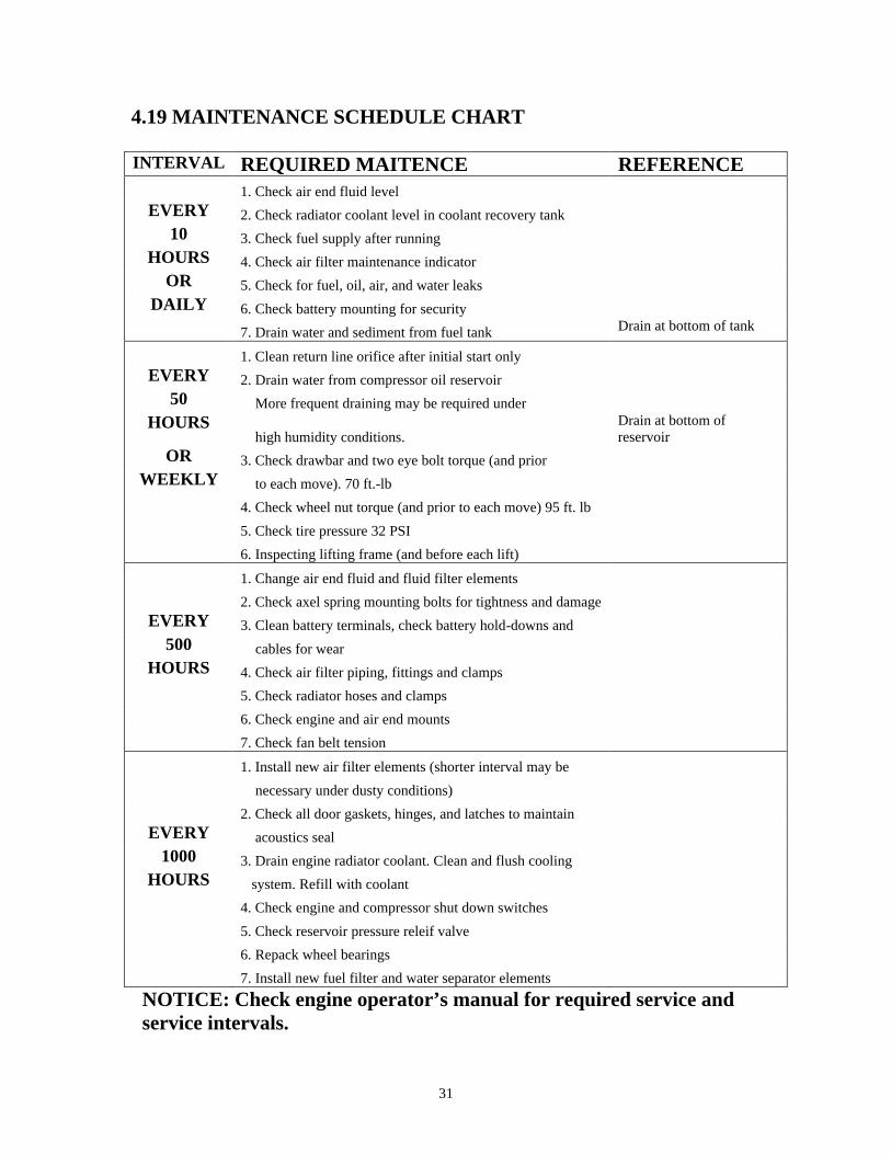
4.19 MAINTENANCE SCHEDULE CHART
INTERVAL REQUIRED MAITENCE REFERENCE 1. Check air end fluid level
EVERY 2. Check radiator coolant level in coolant recovery tank 10 3. Check fuel supply after running
HOURS 4. Check air filter maintenance indicator OR 5. Check for fuel, oil, air, and water leaks
DAILY 6. Check battery mounting for security 7. Drain water and sediment from fuel tank Drain at bottom of tank
1. Clean return line orifice after initial start only EVERY 2. Drain water from compressor oil reservoir
50 More frequent draining may be required under HOURS
high humidity conditions. Drain at bottom of reservoir
OR 3. Check drawbar and two eye bolt torque (and prior WEEKLY to each move). 70 ft.-lb
4. Check wheel nut torque (and prior to each move) 95 ft. lb 5. Check tire pressure 32 PSI 6. Inspecting lifting frame (and before each lift) 1. Change air end fluid and fluid filter elements 2. Check axel spring mounting bolts for tightness and damage
EVERY 3. Clean battery terminals, check battery hold-downs and 500 cables for wear
HOURS 4. Check air filter piping, fittings and clamps 5. Check radiator hoses and clamps 6. Check engine and air end mounts 7. Check fan belt tension 1. Install new air filter elements (shorter interval may be necessary under dusty conditions) 2. Check all door gaskets, hinges, and latches to maintain
EVERY acoustics seal 1000 3. Drain engine radiator coolant. Clean and flush cooling
HOURS system. Refill with coolant 4. Check engine and compressor shut down switches
5. Check reservoir pressure releif valve 6. Repack wheel bearings 7. Install new fuel filter and water separator elements NOTICE: Check engine operator’s manual for required service and service intervals.
32
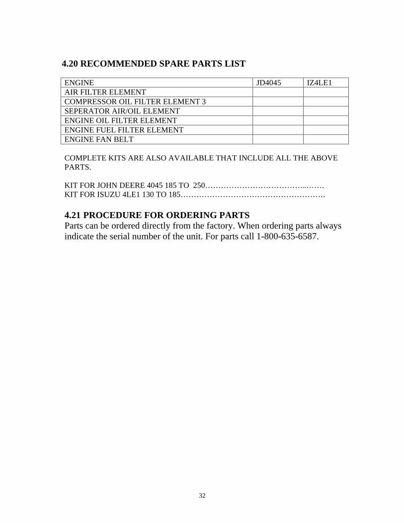
4.20 RECOMMENDED SPARE PARTS LIST
ENGINE JD4045 IZ4LE1 AIR FILTER ELEMENT COMPRESSOR OIL FILTER ELEMENT 3 SEPERATOR AIR/OIL ELEMENT ENGINE OIL FILTER ELEMENT ENGINE FUEL FILTER ELEMENT ENGINE FAN BELT COMPLETE KITS ARE ALSO AVAILABLE THAT INCLUDE ALL THE ABOVE PARTS. KIT FOR JOHN DEERE 4045 185 TO 250………………………………...…….KIT FOR ISUZU 4LE1 130 TO 185………………………………………………. 4.21 PROCEDURE FOR ORDERING PARTS Parts can be ordered directly from the factory. When ordering parts always indicate the serial number of the unit. For parts call 1-800-635-6587.
33
SECTION 5
5.1 TROUBLESHOOTING If the unit will not crank when a “START” is attempted, DO NOT jump-start without first considering the following: • If there is obvious battery damage such as a cracked or broken case,
replace battery • Check for loose battery cables. Tighten if necessary • Check terminals for corrosion, clean if necessary 1. Connect the first jumper cable from positive “+” (red) terminal of the discharged battery to the positive “+” (red) terminal on the booster battery. NEVER connect “+” (red) to “-“ to black. DO NOT PERMIT vehicles to touch each other as this could establish a ground connection
and counteract the benefits of this procedure. 2. Connect one end of second jumper cable to the ground negative “-“
(black) terminal of the booster battery. Connect the other end of this jumper cable to a solid, stationary metallic point on the compressor with the discharged battery but at a point AWAY from the battery (at least 18 inches or more) if possible. DO NOT connect directly to the negative post of the discharged battery.
3. Disconnect positive battery terminal whenever using a high rate charge. Start the compressor in accordance with normal procedure. When the engine is operating smoothly disconnect the jumper cable end at the engine block before disconnecting the jumper cables from the other position. Your Smith Air Compressor has safety switches that protect the engine and compressor from permanent damage. The safety switches are as follows: 1. Engine Oil Pressure: This is a normally open switch that closes with 15
PSI of engine oil pressure. 2. Engine Coolant Temperature: This is a normally closed that opens a
220° F. 3. Compressor Oil Temperature: This is a normally closed switch that
opens at 245°F. All above switches are in series with the power feed to the engine fuel solenoid. If any of the switches open, power to the solenoid is lost and the engine shuts down.
34
WARNING OPERATING WITHOUT SAFETY SWITCHES COULD CAUSE SEVERE PERSONAL INJURY OR DEATH AND CAUSE SIGNIFICANT PROPERTY DAMAGE. IT WILL VOID EXISTING WARRANTIES. ALWAYS INSURE THAT ALL SAFETY SYSTEMS ARE FUNCTIONAL. 5.2 TROUBLESHOOTING CHART
The information contained in the troubleshooting chart has been compiled from field report data and factory experience. It contains symptoms and usual causes for the report data and factory experience. It contains symptoms and usual causes for the described problems; however, do not assume that these are the only problems that may occur. All available data concerning the trouble should be systematically analyzed. Before undertaking any repairs or component replacement procedures, a detailed visual inspection is worth performing for almost all problems and may avoid unnecessary additional damage to the machine. • Check for loose wiring. • Check for damaged piping. • Check for parts damaged by hear or an electrical short circuit, usually
apparent by discoloration or a burnt odor. Should your problem persist after making the recommended checks, consult your nearest Smith Air Compressor distributor or the Smith Air Compressor factory by calling 1-800-635-6587 or (219) 324-7776.
35
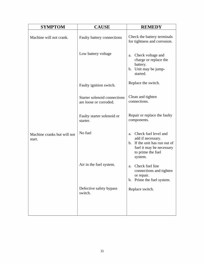
SYMPTOM CAUSE REMEDY
Machine will not crank. Machine cranks but will not start.
Faulty battery connections Low battery voltage Faulty ignition switch. Starter solenoid connections are loose or corroded. Faulty starter solenoid or starter. No fuel Air in the fuel system. Defective safety bypass switch.
Check the battery terminals for tightness and corrosion. a. Check voltage and
charge or replace the battery.
b. Unit may be jump-started.
Replace the switch. Clean and tighten connections. Repair or replace the faulty components. a. Check fuel level and
add if necessary. b. If the unit has run out of
fuel it may be necessary to prime the fuel system.
a. Check fuel line
connections and tighten or repair.
b. Prime the fuel system. Replace switch.
36
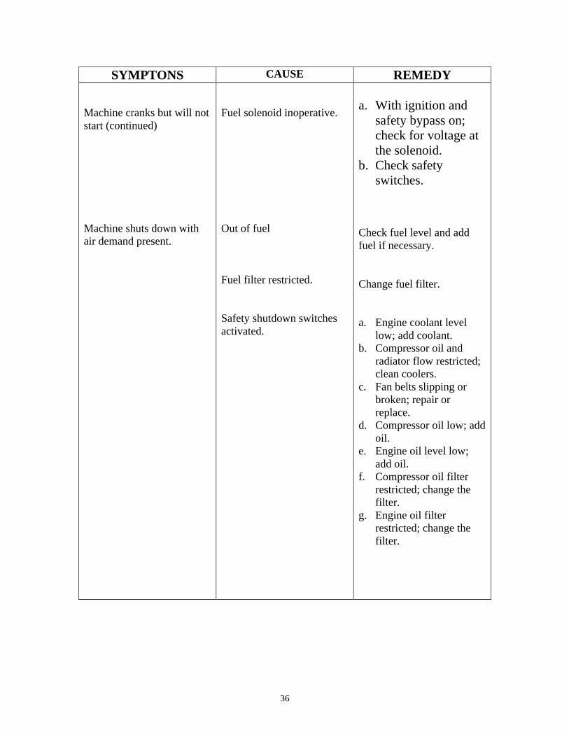
SYMPTONS CAUSE REMEDY Machine cranks but will not start (continued) Machine shuts down with air demand present.
Fuel solenoid inoperative. Out of fuel Fuel filter restricted. Safety shutdown switches activated.
a. With ignition and
safety bypass on; check for voltage at the solenoid.
b. Check safety switches.
Check fuel level and add fuel if necessary. Change fuel filter. a. Engine coolant level
low; add coolant. b. Compressor oil and
radiator flow restricted; clean coolers.
c. Fan belts slipping or broken; repair or replace.
d. Compressor oil low; add oil.
e. Engine oil level low; add oil.
f. Compressor oil filter restricted; change the filter.
g. Engine oil filter restricted; change the filter.
37
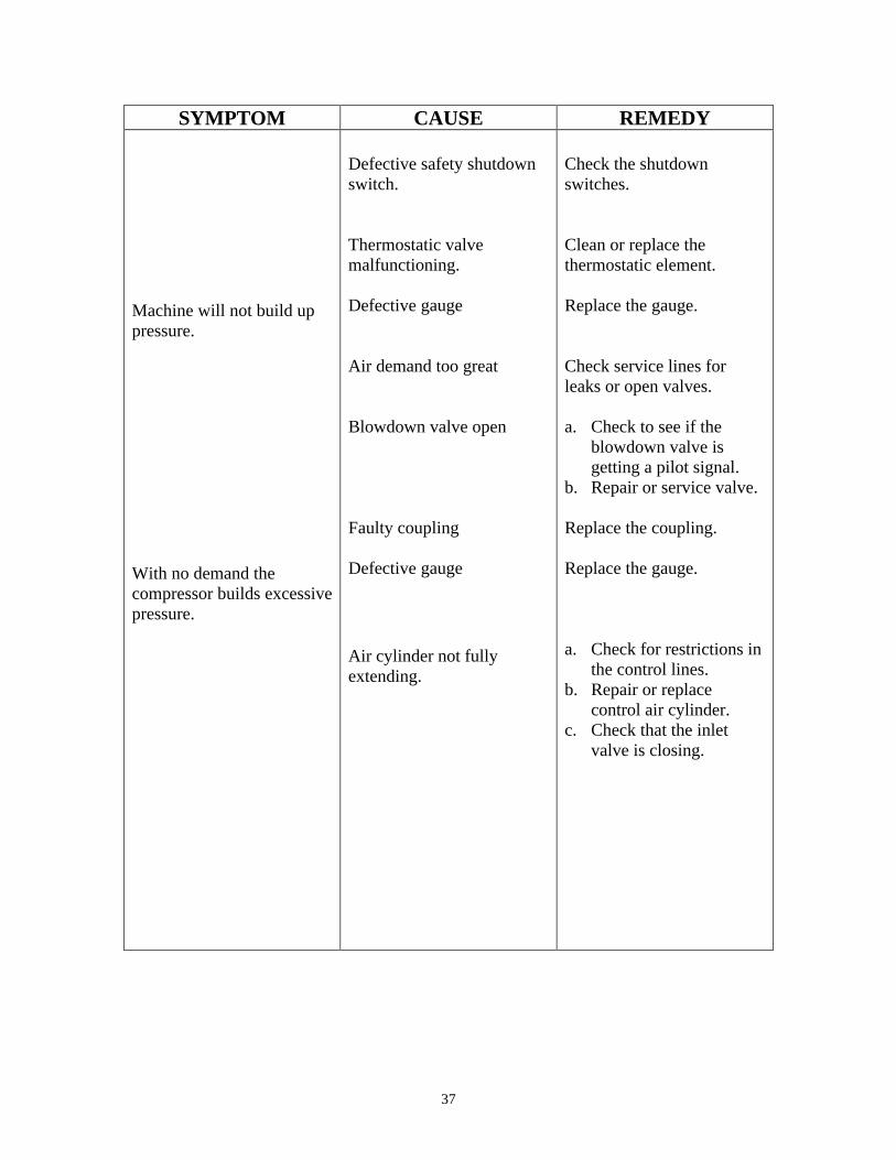
SYMPTOM CAUSE REMEDY Machine will not build up pressure. With no demand the compressor builds excessive pressure.
Defective safety shutdown switch. Thermostatic valve malfunctioning. Defective gauge Air demand too great Blowdown valve open Faulty coupling Defective gauge Air cylinder not fully extending.
Check the shutdown switches. Clean or replace the thermostatic element. Replace the gauge. Check service lines for leaks or open valves. a. Check to see if the
blowdown valve is getting a pilot signal.
b. Repair or service valve. Replace the coupling. Replace the gauge. a. Check for restrictions in
the control lines. b. Repair or replace
control air cylinder. c. Check that the inlet
valve is closing.
38
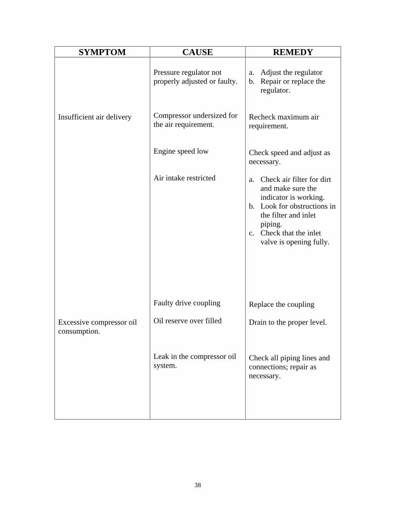
SYMPTOM CAUSE REMEDY Insufficient air delivery Excessive compressor oil consumption.
Pressure regulator not properly adjusted or faulty. Compressor undersized for the air requirement. Engine speed low Air intake restricted Faulty drive coupling Oil reserve over filled Leak in the compressor oil system.
a. Adjust the regulator b. Repair or replace the
regulator. Recheck maximum air requirement. Check speed and adjust as necessary. a. Check air filter for dirt
and make sure the indicator is working.
b. Look for obstructions in the filter and inlet piping.
c. Check that the inlet valve is opening fully.
Replace the coupling Drain to the proper level. Check all piping lines and connections; repair as necessary.
39
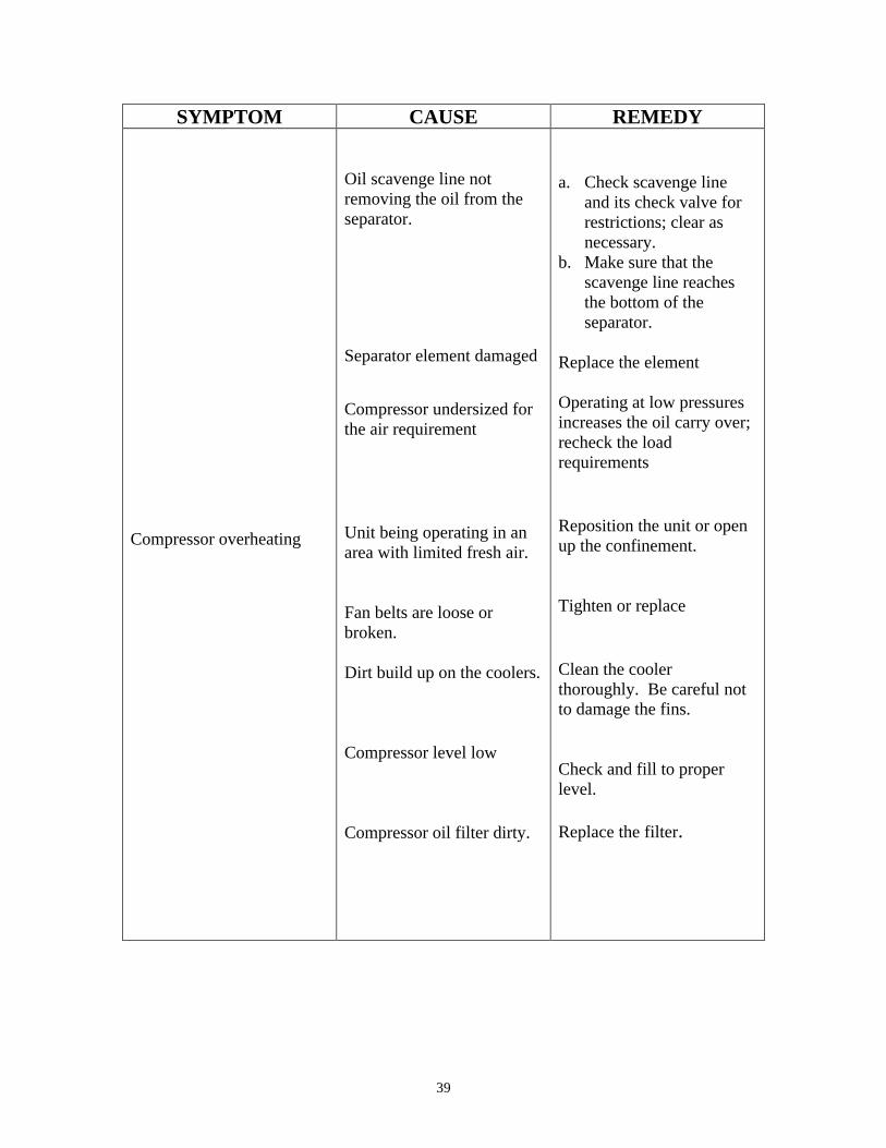
SYMPTOM CAUSE REMEDY Compressor overheating
Oil scavenge line not removing the oil from the separator. Separator element damaged Compressor undersized for the air requirement Unit being operating in an area with limited fresh air. Fan belts are loose or broken. Dirt build up on the coolers. Compressor level low Compressor oil filter dirty.
a. Check scavenge line
and its check valve for restrictions; clear as necessary.
b. Make sure that the scavenge line reaches the bottom of the separator.
Replace the element Operating at low pressures increases the oil carry over; recheck the load requirements Reposition the unit or open up the confinement. Tighten or replace Clean the cooler thoroughly. Be careful not to damage the fins. Check and fill to proper level. Replace the filter.
40
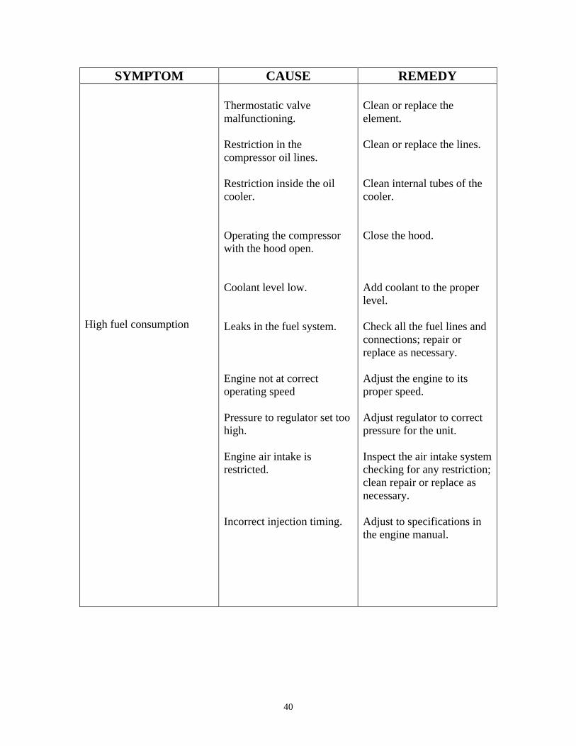
SYMPTOM CAUSE REMEDY High fuel consumption
Thermostatic valve malfunctioning. Restriction in the compressor oil lines. Restriction inside the oil cooler. Operating the compressor with the hood open. Coolant level low. Leaks in the fuel system. Engine not at correct operating speed Pressure to regulator set too high. Engine air intake is restricted. Incorrect injection timing.
Clean or replace the element. Clean or replace the lines. Clean internal tubes of the cooler. Close the hood. Add coolant to the proper level. Check all the fuel lines and connections; repair or replace as necessary. Adjust the engine to its proper speed. Adjust regulator to correct pressure for the unit. Inspect the air intake system checking for any restriction; clean repair or replace as necessary. Adjust to specifications in the engine manual.
41
WARRANTY
Boss Industries, Inc. (BOSS) warrants that this Rotary Screw Compressor unit conforms to applicable drawings and specifications approved in writing by BOSS. The unit assembly will be free from defects in material and workmanship for a period of three (3) years from the date of initial operation or forty-two (42) months from the date of shipment, whichever period first expires. All other components and parts of BOSS manufacture will be free from defects in material and workmanship for a period of one (1) year from the date of initial operation or eighteen (18) months from the date of shipment, whichever period first expires. If within such period BOSS receives from the Buyer written notice of and alleged defect in or nonconformance of the unit, all other components and parts of BOSS manufacture and if in the judgment of BOSS these items do not conform or are found to be defective in material of workmanship, BOSS will at its option either, (a) furnish a Service Representative to correct defective workmanship, or (b) upon return of the item F.O.B. BOSS original shipping point, repair or replace the item or issue credit for the replacement item ordered by Buyer, (Defective material must be returned within thirty (30) days of return shipping instructions from BOSS. Failure to do so within specified time will result in forfeiture of claim), or (c) refund the full purchase price for the item without interest. Factory installed units will also include warranty on installation for a period of one (1) year. This warranty does not cover damaged caused by accident, misuse or negligence. If the compressor unit is disassembled the warranty is void. BOSS’s sole responsibility and Buyer’s exclusive remedy hereunder is limited to such repair, replacement, or repayment of the purchase price. Parts not of BOSS manufacture are warranted only to the extent that they are warranted by the original manufacture. BOSS shall have no responsibility for any cost or expense incurred by Buyer from inability of BOSS to repair under said warranty when such inability is beyond the control of BOSS or caused solely by Buyer.
There are no other warranties, express, statutory or implied, including those of merchantability and of fitness of purpose; nor any affirmation of fact or representation that extends beyond the description of the face hereof.
This warranty shall be void and BOSS shall have no responsibility to repair, replace, or repay the purchase price of defective or damaged parts or components resulting directly or indirectly from the use of repair or replacement parts not of BOSS manufacture or approved by BOSS or from Buyer’s failure to store, install, maintain, and operate the compressor according to the recommendations contained in the Operating and Parts Manual and good engineering practice. The total responsibility of BOSS for claims, losses, liabilities or damages, whether in contract or tort, arising out of or related to its products shall not exceed the purchase price. In no event shall BOSS be liable for any special, indirect, incidental or consequential damages of any character, including, but not limited to, loss of use of productive facilities or equipment, loss of profits, property damage, expenses incurred in reliance on the performance of BOSS, or lost production, whether suffered by Buyer or any third party.
BOSS INDUSTRIES, INC.
1761 GENESIS DR. LAPORTE, IN 46350 (219) 324-7776 Phone (219) 324-7470 Fax

42
SUMMARY OF MAIN WARRANTY PROVISIONS
As claims, policies and procedures are governed by the terms of the BOSS Industries, Inc. (BOSS) warranty, it is necessary to outline some of the more important provisions. The BOSS warranty applies only to new and unused products, which, after shipment from the factory, have not been altered, changed, repaired or mistreated in any manner whatsoever. Normal maintenance items such as lubricants and filters are not warrantable items. Parts not of BOSS manufacture are warranted only to the extent they are warranted by the original manufacturer. Damage resulting from abuse, neglect, misapplication or overloading of a machine, accessory or part is not covered under warranty. Deterioration or wear occasioned by chemical and/or abrasive action or excessive heat shall not constitute defects. Parts replacement and/or correction of defective workmanship will normally be handled by BOSS Industries, Inc. or their authorized distributor. Failure to file a detailed warranty claim/service report for each occurrence of material defect of defective workmanship will cause warranty claim to be rejected. Defective material must be returned within 30 days of receipt of shipping instructions. Failure to do so within specified time will result in forfeiture of claim. The distributor is responsible for the initial investigation and write up of the warranty claim. Distributor shall be allowed no more than 30 days from date of repair to file a warranty claim/service report. Warranty for failure of BOSS replacement parts covers the net cost of the part only, not labor and mileage. The BOSS warranty does not cover diagnostic calls and travel. That is time spent traveling to the machine to analyze the problem and returning with the proper tools and parts to correct the problem. Boss will deduct from allowable credits for excess freight caused by sender failing to follow return shipping instructions. Distributors or end-user automatically deducting the value of a warranty claim from outstanding balances due and payable to BOSS prior to receiving written notification of BOSS approval of the warranty claim may be subject to forfeiture of the entire claim.

43
WARRANTY INTRODUCTION
The warranty policy and procedures outlined here within are detailed to provide the claimant with the information necessary when filing a warranty claim, and enabling BOSS the ability to serve it’s customers best.
WARRANTY CLAIMS - GENERAL
An approved claim depends on the following provision: 1. A warranty claim/service report # must be issued by BOSS. (See filing procedures). 2. Failed part must be returned within 30 days, freight prepaid, with receipt of warranty claim/service
report. 3. Part is definitely defective. 4. Workmanship is definitely defective. 5. Machine is within warranty period. 6. Machine has been operating within design conditions. Claims made by distributors must be verified by distributor prior to contacting BOSS.
WARRANTY CLAIMS - INSTRUCTIONS FOR SUBMITTING CLAIM
When making a warranty claim, study the situation that led up to the failure carefully. Verify that the failure wan not the result of abuse or negligence. Warranty claims are not considered under normal machine maintenance.
WARRANTY CLAIMS - FILING PROCEDURES
1. Initiate through purchase order for warranty part or request for credit. 2. Warranty Claims/Service Report will accompany replacement part. When returning failed part to the
factory for warranty credit, fill out all information requested on Warranty Claims/Service Report when it is returned to you with replacement part.
3. BOSS will confirm disposition of failed part within 30 days, and or request additional information. 4. Claim acceptance or denial will result in release of a credit or confirmation letter of denial. 5. BOSS will consider each claim on it’s own merit and reserves the right to accept or reject claim
request. In case of air-ends, these will be returned to the manufacturer for their analysis/input. 6. Send Warranty Claim/Service Report request to:
BOSS INDUSTRIES, INC. 1761 GENESIS DRIVE LAPORTE, IN 46350 ATTN: WARRANTY CLAIM ENCLOSED
44
WARRANTY CLAIMS - PREPARATION OF PART FOR RETURN
Parts returned to the factory must be properly packaged to prevent damage during shipment. Damage to a part as a result of improper handling or packing could be cause for claims disallowance of credit. When addressing the package for shipment, the following information must be on outside of or tagged clearly to package. 1. Return Goods authorization. 2. Distributor or end-users return address. 3. Correct factory address. 4. Warranty Claim/Service Report #. 5. Number of packages pertaining to each claim. NOTE: Our warranty requires that all defective parts be returned to BOSS freight prepaid. Items sent without RGA number will not be accepted.

45
NOTES