pto air compressor operators, installation and parts ...bossair.com/manuals/80200ibi.pdf · 1 boss...
TRANSCRIPT

1BOSS Industries, Inc.PTO Air Compressor (IBI Split-Shaft)Operators, Installation and Parts Manual
PTO AIR COMPRESSOROPERATORS, INSTALLATION
AND PARTS MANUAL(IBI SPLIT-SHAFT)
301367 Revised 6/5/01

BOSS Industries, Inc.PTO Air Compressor (IBI Split-Shaft)Operators, Installation and Parts Manual 2
OPERATORS, INSTALLATION, AND PARTS MANUAL
TABLE OF CONTENTS
Operation & Maintenance Section
General Arrangement . . . . . . . . . . . . . . . . . . 3
Specifications . . . . . . . . . . . . . . . . . . . . . . 4
Safety . . . . . . . . . . . . . . . . . . . . . . . . . 10
Compressor Terminology . . . . . . . . . . . . . . . . . 11
Description of Components . . . . . . . . . . . . . . . . 12-17
Inspection, Lubrication, and Maintenance . . . . . . . . . 25
Troubleshooting . . . . . . . . . . . . . . . . . . . . 26-30
Compressor Operation . . . . . . . . . . . . . . . . . 31-33
Installation Section
Installation Instructions . . . . . . . . . . . . . . . . . . 34-46
Parts & Illustration Section
Parts and Illustration Section . . . . . . . . . . . . . . . . 47-62
Warranty Section & Recommended Spare Parts List
Warranty Information . . . . . . . . . . . . . . . . . . . 63-68
Recommended Spare Parts List . . . . . . . . . . . . . . . 69

3BOSS Industries, Inc.PTO Air Compressor (IBI Split-Shaft)Operators, Installation and Parts Manual
GENERAL ARRANGEMENT
Boss Underdeck PTO Compressors are shipped in kit form for field installation. Thesekits include:
1. Rotary Screw Compressor, Split-shaft Gear Box, and Mounting Bracket. Page 59
2. Oil Sump with Mounting Brackets. Page 56
3. Spin-on Coalescer/Air Manifold Assembly. Page 56
4. Compressor Oil Cooler/Fan Assembly or Optional Front Mount Cooler Without Fan Assembly. Page 60 and 61
5. Load Controller. Page 54
6. Air Inlet Filtration System. Page 52
7. Hoses and Fittings
8. All Necessary Safety and Informational Decals
9. Instrument Panel Assembly/Wiring. Page 50
10. Oil Filter Assembly. Page 60-
11. PTO and Drivelines (Optional accessories).
12. Parts, Service, and Maintenance.
Boss Industries offers factory installation by qualified technicians, as well as anationwide network of authorized distributors for field installations, parts and service.

BOSS Industries, Inc.PTO Air Compressor (IBI Split-Shaft)Operators, Installation and Parts Manual 4
SPECIFICATIONS
MODEL 80200-IBI (SPLIT-SHAFT)
COMPRESSORDelivery @ 110 PSIG* 125 CFM 150 CFM 175 CFMInput Speed 975 RPM 1165 RPM 1333 RPMFluid Capacity (gallons) 4.75 GAL 4.75 GAL 4.75 GAL
COMPONENTS (Overall Dimensions)
Compressor/Split-Shaft 22.0” W x 16.5” H x 26.0” LReceiver/Sump 12.0” DIA x 22.0” LSpin-On Coalescer 5.0” DIA x 13.0” HCooler/Fan Assembly 19.0” W x 12.0” H x 22.0” LEngine Speed Control 7.5” W x 3.0” H x 14.0” LGauge Package 4.75” W x 3.0” H x 8.0” LAir Inlet Filter 5.75 DIA x 11.88” LWeight (dry) est 675 LBS.
*125 & 150 PSIG options available. Consult factory.
SPECIFICATIONS SUBJECT TO CHANGE WITHOUT PRIOR NOTICE

5BOSS Industries, Inc.PTO Air Compressor (IBI Split-Shaft)Operators, Installation and Parts Manual
SAFETY
WARNING
ALL UNITS ARE SHIPPED WITH A DETAILED OPERATORS, INSTALLATION ANDPARTS MANUAL. THIS MANUAL CONTAINS VITAL INFORMATION FOR THE SAFE
USE AND EFFICIENT OPERATION OF THIS UNIT. CAREFULLY READ THEOPERATORS MANUAL BEFORE STARTING THE UNIT. FAILURE TO ADHERE TO
THE INSTRUCTIONS COULD RESULT IN SERIOUS BODILY INJURY OR PROPERTYDAMAGE.
AIR COMPRESSOR SAFETY PRECAUTIONS
Safety is basically common sense. There are standard safety rules but eachsituation has its own peculiarities which cannot always be covered by rules.Therefore with your experience and common sense, you are in a position to dosomething about safety. Lack of attention to safety can result in: accidents,personal injury, reduction of efficiency and worst of all - loss of life. Watch for safetyhazards. Correct them promptly. Use the following safety precautions as a generalguide to safe operation:
Do not attempt to remove any compressor parts without first relieving the entiresystem of pressure.
Do not attempt to service any part while machine is operating.
DANGER
CHECK THE COMPRESSOR SUMP OIL LEVEL ONLY WHEN THE COMPRESSOR ISNOT OPERATING AND SYSTEM IS COMPLETELY RELIEVED OF PRESSURE. OPEN
SERVICE VALVE TO INSURE RELIEF OF SYSTEM AIR PRESSURE WHENPERFORMING MAINTENANCE ON COMPRESSOR AIR/OIL SYSTEM. FAILURE TO
COMPLY WITH THIS WARNING MAY CAUSE DAMAGE TO PROPERTY AND SERIOUSBODILY HARM.
Do not operate the compressor at pressures or speeds in excess of its rating asindicated in “Compressor Specifications”.
Periodically check all safety devices for proper operation.
Do not play with compressed air. Pressurized air can cause serious injury topersonnel.
Exercise cleanliness during maintenance and when making repairs. Keep dirt awayfrom parts by covering parts and exposed openings.

BOSS Industries, Inc.PTO Air Compressor (IBI Split-Shaft)Operators, Installation and Parts Manual 6
SAFETY
Do not install a shut-off valve between the compressor and compressor oil sump.
DANGER
DO NOT USE BOSS INDUSTRIES, INC. COMPRESSORS TO PROVIDE BREATHINGAIR. SUCH USAGE, WHETHER SUPPLIED IMMEDIATELY FROM THE COMPRESSOR
SOURCE, OR SUPPLIED TO BREATHING TANKS FOR SUBSEQUENT USE, CANCAUSE SERIOUS BODILY INJURY.
BOSS INDUSTRIES, INC. DISCLAIMS ANY AND ALL LIABILITIES FOR DAMAGE ORLOSS DUE TO PERSONAL INJURIES, INCLUDING DEATH, AND/OR PROPERTY
DAMAGE INCLUDING CONSEQUENTIAL DAMAGES ARISING OUT OF ANY BOSSCOMPRESSORS USED TO SUPPLY BREATHING AIR.
Do not disconnect or by-pass safety circuit system.
Do not install safety devices other than authorized Boss replacement devices.
Close all openings and replace all covers and guards before operating compressorunit.
Tools, rags, or loose parts must not be left on the compressor or drive parts.
Do not use flammable solvents for cleaning parts.
Keep combustibles out of and away from the compressor and any associatedenclosures.
The owner, lessor, or operator of the compressor are hereby notified andforewarned that any failure to observe these safety precautions may result indamage or injury.
Boss Industries, Inc. expressly disclaims responsibility or liability for any injury and/ordamage caused by failure to observe these specified precautions or by failure toexercise that ordinary caution and due care required when operating or handlingthe compressor, even though not expressly specified above.

7BOSS Industries, Inc.PTO Air Compressor (IBI Split-Shaft)Operators, Installation and Parts Manual
SAFETY
A compliment of warning decals are supplied with each unit. These decals shouldbe affixed to the vehicle after it has been painted, trimmed, and undercoated, etc.and prior to being put into service. The decals should be placed so as to be clearlyvisible to the user and service personnel. (Figures 1thru 8)
Figure 1. To be placed Figure 2. To be placedon visor or dash near on body near oil sumpstart-up procedure decal. filler cap.

BOSS Industries, Inc.PTO Air Compressor (IBI Split-Shaft)Operators, Installation and Parts Manual 8
SAFETY
Figure 3. To be placed Figure 4. To be placedon body near air service on body near air servicevalve.` valve.

9BOSS Industries, Inc.PTO Air Compressor (IBI Split-Shaft)Operators, Installation and Parts Manual
SAFETY
Figure 5. To be placed Figure 6. To be placedon frame near compressor on fan shroud.mounting foot.

BOSS Industries, Inc.PTO Air Compressor (IBI Split-Shaft)Operators, Installation and Parts Manual 10
SAFETY
Figure 7. To be placed on body near oil sump filler cap.
Figure 8. Serial number/name plate to be placed on drivers side door jam.

11BOSS Industries, Inc.PTO Air Compressor (IBI Split-Shaft)Operators, Installation and Parts Manual
COMPRESSOR TERMINOLOGY
ATF: Automatic transmission fluid.
AIR/OIL COALESCER: Performs second stage separation of oil from compressed airfeeding air tools. Sometimes referred to as the separator element.
CFM: Refers to the volume of compressed air being produced expressed as cubicfeet of air per minute.
LOAD CONTROLLER: Sometimes referred to as the engine speed control.
OIL SUMP: The first stage of oil separation from compressed air. Also serves asreservoir area for compressor lubricant and sometimes referred to as the receivertank.
PSI: Refers to the operating pressure the system is set up at, expressed as poundsper square inch.
SAFETY VALVE: A valve located on the oil sump which opens in case of excessivepressure. Sometimes referred to as the pop-off or pressure relief valve.
SHUTDOWN SWITCH: Works in conjunction with temperature and pressureswitchgauges, sending a signal to stop the compressor power source in cases ofhigh temperature or pressure.
SPLIT-SHAFT PTO: Transfer case gear box with integrally mounted compressortransmits engine power and torque from the main driveshaft. The PTO gear box ismounted to the frame rail sides with special mounting brackets behind thetransmission. With the PTO engaged, the rear driveline is stationary while the frontdriveline rotates into the gear box automatically starting operation of the integrallymounted air compressor. With the PTO disengaged, the front driveshaft transmitspower through the box to the rear driveshaft and rear axle.

BOSS Industries, Inc.PTO Air Compressor (IBI Split-Shaft)Operators, Installation and Parts Manual 12
DESCRIPTION OF COMPONENTS
PRINCIPLES OF OPERATION
In operation, two helically grooved rotors mesh to compress air. Inlet air is trappedas the male lobes roll down the female grooves, pushing trapped air along,compressing it until it reaches the discharge port in the end of the stator anddelivers smooth-flowing, pulse-free air to the receiver.
During the compression cycle, oil is injected into the compressor and serves thesepurposes:
1. Lubricates the rotating parts and bearings. 2. Serves as a cooling agent for the compressed air. 3. Seals the running clearances.
LUBRICATION SYSTEM
Oil from the compressor oil sump, at compressor discharge pressure, is directedthrough the oil filter, cooling system, and to the side of the compressor stator, whereit is injected into the compressor. At the same time oil is directed internally to thebearings and shaft seal of the compressor. The oil-laden air is then dischargedback into the sump.
OIL SUMP
Compressed, oil-laden air enters the sump from the compressor. As the oil-laden airenters the sump, most of the oil is separated from the air as it passes through a seriesof baffles and de-fusion plates. The oil accumulates at the bottom of the sump forre-circulation. However, some small droplets of oil remain suspended in the air andare passed on to the coalescer.
SAFETY VALVE
The pop safety valve is set at 170 PSI and is located at the top of the air/oil sump.This valve acts as a backup to protect the system from excessive pressure thatmight result from a malfunction.
AIR/OIL COALESCER
The coalescer is self-contained within a spin-on housing and is independent of thesump. When air is demanded at the service line, it passes through the coalescerwhich efficiently provides the final stage of oil separation.

13BOSS Industries, Inc.PTO Air Compressor (IBI Split-Shaft)Operators, Installation and Parts Manual
DESCRIPTION OF COMPONENTS
OIL RETURN LINE
The oil that is removed by the coalescer accumulates at the bottom of the canand is returned through an oil return line leading to the compressor. The oil returnline also contains a check valve which is located at the compressor.
MINIMUM PRESSURE ORIFICE
The minimum pressure orifice is located at the outlet of the coalescer head andserves to maintain a minimum discharge pressure of 60 PSIG in operation, which isrequired to assure adequate compressor lubrication pressure.
OIL FILTER
The compressor oil filter is the full-flow replaceable element type and has a safetyby-pass built into it.
COMPRESSOR COOLING SYSTEM
The compressor cooling system consists of an oil cooler, electric fan motor, and fan.The fan/cooler package is self-contained in an aerodynamically designed housingallowing for several optional mounting locations.
An automated thermostatic control system maintains a continuos temperaturecheck of the lubricant. It then sends an electrical signal to the fan/cooler packageforcing ambient air over the cooler fins ensuring a proper operating temperature.
NOTE
IN SOME OPTIONAL CASES THE OIL COOLER MAY BE MOUNTED IN FRONT OFTHE VEHICLE RADIATOR. IN THIS CASE AN OIL THERMAL VALVE MIXES OIL
FROM COMPRESSOR AND OIL COOLER TO MAINTAIN OIL AT 180°F OILTEMPERATURE.

BOSS Industries, Inc.PTO Air Compressor (IBI Split-Shaft)Operators, Installation and Parts Manual 14
DESCRIPTION OF COMPONENTS
ELECTRICAL AND SAFETY CIRCUIT SYSTEM
The Boss PTO unit is supplied with a 12 volt DC fan switch, electric fan motor,temperature switchgauge, hourmeter, pressure switchgauge, and a shutdownswitch. The switchgauges activate a shutdown switch in cases of high dischargetemperature or high sump pressure.
INSTRUMENTATION
The Boss PTO unit is equipped with a discharge air pressure switchgauge, adischarge air/oil temperature switchgauge, and a 12 volt DC electric hourmeterwith pressure switch. All components are mounted on a compact instrument panelthat can be located where desired.
COMPRESSOR DISCHARGE PRESSURE SWITCHGAUGE
This switchgauge indicates the discharge air/oil pressure. Operate the compressorwithin discharge pressure limits as indicated in the specifications section. Theswitchgauge ensures high pressure safety shutdown before the safety relief valveon the sump is discharged, preventing hot pressurized oil spray on the vehicle and/or compressor components.
HOURMETER
The hourmeter records the total number of operating hours. It serves as a guidetowards following the recommended inspection and maintenance schedule. Thehourmeter will only run when there is pressure in the system.
COMPRESSOR DISCHARGE AIR/OIL TEMPERATURE SWITCHGAUGE
This switchgauge indicates compressor air discharge temperature. Theswitchgauge ensures safety shutdown in case of excessive operating temperatures,preventing compressor damage.

15BOSS Industries, Inc.PTO Air Compressor (IBI Split-Shaft)Operators, Installation and Parts Manual
DESCRIPTION OF COMPONENTS
AUTOMATIC BLOWDOWN VALVE(S)
There may be two blowdown valves in the compressor system. One blow-downvalve is located at the downstream side of the coalescer head and willautomatically bleed the sump to zero pressure when the compressor is disengaged.On vehicles without electronic controlled engines, the other blowdown valve(controller blowdown valve) is located at the load controller ) and vents the air inthe cylinder when the compressor is disengaged to quickly return the truck’s engineto idle.On compressor units equipped with an electronic speed control the load controllerblow-down valve is not required.
CONTROL SYSTEM
The prime components of the compressor control system include the compressorinlet valve and a load controller. The control system is designed to match air supplyto air demand and to prevent excessive discharge pressure when compressor is atidle. Control of air delivery is accomplished by both the inlet valve regulation andload controller modulation as directed by the discharge pressure regulator.
DISCHARGE PRESSURE REGULATOR VALVE
This valve, located on the load controller (or the coalescer head depending onoptional equipment), is used to select the desired discharge pressure within theoperating pressure range. Turning the regulator screw clockwise increases theworking pressure, a counterclockwise movement of the screw reduces the workingpressure.
INLET VALVE
The compressor inlet valve is a piston operated disc valve that has a dual functionof regulating the inlet opening to control capacity and serving as a check valve atshutdown.

BOSS Industries, Inc.PTO Air Compressor (IBI Split-Shaft)Operators, Installation and Parts Manual 16
DESCRIPTION OF COMPONENTS
On compressor packages with a programmable electronic engine speed controlsystem. The compressor will automatically go to high idle when the split shaft isengaged. Depending on the programming variables available on your specificengine the truck may fluctuate between a high-speed setting and a low-speedsetting depending upon air demand. Timers are incorporated into this system toeliminate the rapid acceleration and deceleration of the engine during use.
Consult the wire diagram incorporated at the end of this manual for informationspecific to your vehicle.
CONTROL SYSTEM OPERATION (AIR CYLINDER SYSTEM)
The following discussion explains the operation of the control system from acondition of “no load” to a condition of “full capacity” at working pressure. For theworking pressure range of your machine, refer to applicable data in“Specifications”.
The pressure regulator, mounted on the load controller or coalescer head,operates as follows:
1. As the demand for air decreases, the receiver pressure rises. When this pressure exceeds the set point of the pressure regulator, the regulator opens sending a secondary pressure signal to the inlet valve (bottom port) and to the regulating cylinder.
a. The regulating cylinder will reduce engine speed.
b. The inlet valve disc moves towards the valve inlet against the force of the modulating spring inside the valve. This regulates the opening area of the inlet valve.
2. If the air demand goes to zero, (service valve closed) the inlet valve will close completely, and the regulating cylinder will bring the engine to idle.
3. As the demand for air increases, the procedure is reversed.
The heart of the system is the Boss Load Controller (Page 53). This compact loadcontroller regulates the speed of the engine and the opening of the inlet valve ofthe compressor to give 0 - 100% stepless capacity control.

17BOSS Industries, Inc.PTO Air Compressor (IBI Split-Shaft)Operators, Installation and Parts Manual
DESCRIPTION OF COMPONENTS
The Boss Load Controller includes two pneumatic cylinders - an arming cylinder anda regulating cylinder. The arming cylinder becomes fullyextended immediately after startup and takes over control of the engine bytightening the ball chain at the engine throttle. The arming cylinder remains fullyextended while the compressor is operating.
The regulating cylinder reacts to pressure signals from the pressure regulator andregulates the speed of the engine from idle to full speed in accordance to the airdemand requirements.

BOSS Industries, Inc.PTO Air Compressor (IBI Split-Shaft)Operators, Installation and Parts Manual 18
INSPECTION, LUBRICATION, AND MAINTENANCE
This section contains instructions for performing the inspection, lubrication, andmaintenance procedures required to maintain the compressor in proper operatingcondition. The importance of performing the maintenance described hereincannot be over emphasized.
The periodic maintenance procedures to be performed on the equipment coveredby this manual are listed below. It should be understood that the intervals betweeninspections specified are maximum interval. More frequent inspections should bemade if the unit is operating in a dusty environment, in high ambient temperature,or in other unusual conditions. A planned program of periodic inspection andmaintenance will help avoided pre-mature failure and costly repairs. Daily visualinspections should become a routine.
The LUBRICATION AND MAINTENANCE CHART lists serviceable items on thecompressor package. The items are listed according to their frequency ofmaintenance, followed by those items which need only “As Required”maintenance.
The maintenance time intervals are expressed in hours. The hourmeter shows thetotal number of hours your compressor has run. Use the hourmeter readings fordetermining your maintenance schedules. Perform the maintenance at multipleintervals of the hours shown. For example, when the hourmeter shows “100” on thedial, all items listed under “EVERY 10 HOURS” should be serviced for the tenth time,and all items under “EVERY 50 HOURS” should be serviced for the second time, andso on.
DANGER
COMPRESSOR MUST BE DISENGAGED AND COMPLETELY RELIEVED OFPRESSURE PRIOR TO CHECKING FLUID LEVELS. OPEN SERVICE VALVE TOASSURE RELIEF SYSTEM AIR PRESSURE. FAILURE TO COMPLY WITH THIS
WARNING MAY CAUSE DAMAGE TO PROPERTY AND/OR SERIOUS BODILY HARM.


BOSS Industries, Inc.PTO Air Compressor (IBI Split-Shaft)Operators, Installation and Parts Manual 20
LUBRICANT RECOMMENDATIONS
WARNING
IT IS IMPORTANT THAT THE COMPRESSOR OIL BE OF A RECOMMENDED TYPEAND THIS OIL AS WELL AS THE AIR FILTER, OIL FILTER AND COALESCERELEMENTS BE INSPECTED AND REPLACED AS STATED IN THIS MANUAL.
THE COMBINATION OF A COALESCER ELEMENT LOADED WITH DIRT ANDOXIDIZED OIL PRODUCTS TOGETHER WITH INCREASED AIR VELOCITY AS ARESULT OF THIS CLOGGED CONDITION MAY PRODUCE A CRITICAL POINT
WHILE THE MACHINE IS IN OPERATION WHERE IGNITION CAN TAKE PLACE ANDCOULD CAUSE A FIRE IN THE OIL SUMP.
FAILURE TO COMPLY WITH THIS WARNING MAY CAUSE DAMAGE TO PROPERTYAND SERIOUS BODILY HARM.
The following general characteristics categorize lubricants which have been foundto be satisfactory for use in Boss PTO helical screw type air compressors. Due to theimpossibility of establishing limits on all physical and chemical properties oflubricants which can affect their performance in the compressor over a broadrange of environmental influences, the responsibility for recommending andconsistently furnishing a suitable heavy duty lubricant must rest with the individualsupplier. The lubricant supplier’s recommendation must, therefore, be based uponnot only the following general characteristics, but also upon his own knowledge ofthe suitability of the recommended lubricant in PTO helical screw type aircompressors operating in the particular environment involved.
CAUTION
MIXING DIFFERENT TYPES OR BRANDS OF LUBRICANTS IS NOT RECOMMENDEDDUE TO THE POSSIBILITY OF A DILUTION OF THE ADDITIVES OR A REACTION
BETWEEN ADDITIVES OF DIFFERENT TYPES.

21BOSS Industries, Inc.PTO Air Compressor (IBI Split-Shaft)Operators, Installation and Parts Manual
LUBRICANT RECOMMENDATIONS
Not all lubricating oils are suitable for rotary screw compressor use. The mostsatisfactory oils are the detergent types which contain high levels of corrosion,oxidation, and foam inhibitors.
Boss factory installations use Dexron II automatic transmission fluid. Other detergentmotor oils, SAE10W, class SF or CD, and SAE 30 meet these requirements.
The viscosity of the oil chosen depends largely on the ambient operatingtemperature range. The oil must provide sufficient lubrication for bearings androtors at operating temperature, and it must have a pour point low enough toprovide fluidity at low starting temperatures. In general, the viscosity rangepresented by these SAE grades is satisfactory for the temperature range shown:
+40 F To + 120 F SAE 30-10 F To + 75 F SAE 10 W (-20 F Pour Point)-40 F To + 100 F ATF (-50 F Pour Point)
PRIME LUBRICANT CHARACTERISTICS
1. Flash point 400° F minimum (ASTM D-92 — COC).2. Pour point must be at least 20° F lower than the lowest expected
ambient temperature.3. Contain rust and oxidation inhibitors.4. Contain foam suppressers.
SYNTHETIC DIESTER AND SYNTHESIZED HYDROCARBON LUBRICANTS OIL
Insofar as known, all elastomeric components and all metal used in the compressorare fully compatible with synthetic diester and synthesized hydrocarbon lubricants.The viscosity grade chosen for synthetic diester base or SHC lubricants should bebased upon the suggested viscosity ranges listed under prime lubricantcharacteristics and the lubricant supplier.

BOSS Industries, Inc.PTO Air Compressor (IBI Split-Shaft)Operators, Installation and Parts Manual 22
LUBRICANT RECOMMENDATIONS
NOTE
DUE TO UNKNOWN INFLUENCES OF ENVIRONMENTAL FACTORS SUCH AS THEINTAKE OF REACTIVE GASES OR VAPORS IN THE AIR WHICH MAY LEAD TO
CHEMICAL CHANGES IN ANY OIL AND PREMATURE FAILURE OF THE LUBRICANT,THE USEFUL LIKE OF ALL “EXTENDED LIFE” LUBRICANTS MAY BE SHORTER
THAN QUOTED BY THE LUBRICANT SUPPLIER. BECAUSE THE NORMAL “DRAINAND REPLACE” PERIOD MAY BE EXCEEDED USING SYNTHETIC LUBRICANTS,
DIFFERING FROM THOSE SPECIFIED IN THIS MANUAL, BOSS ENCOURAGES THEUSER TO CLOSELY MONITOR THE LUBRICANT CONDITION AND TO PARTICIPATE
IN AN OIL ANALYSIS PROGRAM WITH THE SUPPLIER.
NOTE
NO LUBRICANT, HOWEVER GOOD AND/OR EXPENSIVE, CAN REPLACE PROPERMAINTENANCE AND ATTENTION. SELECT AND USE WISELY.
COMPRESSOR OIL SUMP FILL, LEVEL, AND DRAIN
Before adding or changing compressor oil make sure that the system is disengagedand the sump is completely relieved of pressure. Oil is added at the fill cap in thetee on the side of the receiver/sump (Page 55). A drain plug is provided at thebottom of the sump. The proper oil level, when unit is disengaged and has hadtime to settle, is at the midpoint of the oil sight glass. The truck must be level whenchecking the oil. DO NOT OVERFILL. The oil sump capacity is given in “CompressorSpecifications”.
DANGER
DO NOT ATTEMPT TO DRAIN CONDENSATE, REMOVE THE OIL LEVEL FILL PLUGOR BREAK ANY CONNECTION IN THE AIR OR OIL SYSTEM WITHOUT
DISENGAGING THE COMPRESSOR AND MANUALLY RELIEVING PRESSURE FROMTHE SUMP. FAILURE TO COMPLY WITH THIS WARNING MAY CAUSE DAMAGE TO
PROPERTY AND SERIOUS BODILY HARM.
GREASE
Lubricate the compressor drive shaft universal joints every time the truck islubricated or every 100 hours of compressor operation, whichever comes first.

23BOSS Industries, Inc.PTO Air Compressor (IBI Split-Shaft)Operators, Installation and Parts Manual
MAINTENANCE
MAINTENANCE
If some of the maintenance intervals in the schedule outlined in this manual seemto be rather short, it should be considered that one hour’s operation of acompressor is equal to about 40 road miles on an engine. Thus, eight hoursoperation is equal to 320 road miles, 250 hours is equal to 10,000 road miles, etc.
AIR INTAKE FILTER
The air intake filter is a heavy-duty two-stage dry type high efficiency filter designedto protect the compressor from dust and foreign objects.
The filter is equipped with an evacuator cup for continuous dust ejection whileoperating and when stopped.
Frequency of maintenance of the filter depends on dust conditions at theoperating site. The filter element must be serviced when clogged (maximumpressure drop for proper operation is 15” H2O).
AIR/OIL COALESCER
The air/oil coalescer employs an element permanently housed within a spin-oncanister. This is a single piece unit that requires replacement when it fails to removethe oil from the discharge air, or the pressure drop across it exceeds 15 PSI. Dirty oilincreases the pressure drop across the coalescer element.
To replace element proceed as follows:
1. Disengage the compressor and wait for complete blowdown (zero pressure).
2. Disconnect drain line.3. Turn element counterclockwise for removal.4. Install new rubber seal in head and supply a film of fluid directly
to seal.5. Rotate element clockwise by hand until element contacts seal.6. Rotate element approximately one more turn clockwise with
band wrench near the top of element.7. Reconnect drain line.8. Run system and check for leaks.

BOSS Industries, Inc.PTO Air Compressor (IBI Split-Shaft)Operators, Installation and Parts Manual 24
MAINTENANCE
WARNING
DO NOT SUBSTITUTE AIR/OIL ELEMENT. USE ONLY A GENUINE BOSSREPLACEMENT ELEMENT. THIS ELEMENT IS RATED AT 200 PSI WORKING
PRESSURE. USE OF ANY OTHER ELEMENT MAY BE HAZARDOUS AND COULDIMPAIR THE PERFORMANCE AND RELIABILITY OF THE COMPRESSOR, POSSIBLYVOIDING THE WARRANTY AND/OR RESULTING IN DAMAGE TO PROPERTY AND
SERIOUS BODILY HARM.
OIL RETURN LINE
This line originates at the bottom of the air/oil coalescer and flows through a checkvalve located at the air-end. The check valve ensures that back flow to coalescerelement does not occur during shutdown. If excessive oil consumption or carryover is present, check to make certain this line is not clogged or plugged at thecheck valve.
OIL FILTER
The compressor oil filter is a spin-on, throw away type.
To replace filter proceed as follows:
1. Disengage and make sure system pressure is relieved.2. Remove filter by unscrewing from filter head (turn
counterclockwise by hand) and discard.3. Install a new filter by applying a little oil to the seal
and then screw the filter on by hand (turning it clockwise until hand tight, plus one - third turn). Do not use tools to tighten the filter.
4. Check for leaks in operation.
WARNING
DO NOT SUBSTITUTE OIL FILTER ELEMENT. USE ONLY A GENUINE BOSSREPLACEMENT ELEMENT. THIS ELEMENT IS RATED AT 200 PSI WORKING
PRESSURE. USE OF ANY OTHER ELEMENT MAY BE HAZARDOUS AND COULDIMPAIR THE PERFORMANCE AND RELIABILITY OF THE COMPRESSOR, POSSIBLYVOIDING THE WARRANTY AND/OR RESULTING IN DAMAGE TO PROPERTY AND
SERIOUS BODILY HARM.

25BOSS Industries, Inc.PTO Air Compressor (IBI Split-Shaft)Operators, Installation and Parts Manual
MAINTENANCE
OIL COOLER
The oil cooler is basically maintenance free. It should be inspected periodically forexcessive accumulation of dirt and dust that will impede its performance. Also seeService Interval Chart on page 18.
The interior of the oil cooler should be cleaned when the pressure drop across it atfull flow exceeds 25 PSI. The following procedure has been recommended by thevendor who supplies the cooler:
1. Remove cooler.
2. Circulate a suitable solvent to dissolve and remove varnish and sludge.
3. Flush generously with oil.
4. After cooler is reinstalled, fill sump reservoir with fresh oil. See Service Interval Chart on page 18.
COMPRESSOR SHAFT OIL SEAL
The compressor shaft seal is used to retain fluid in compressor and gear lube in gearhousing.
NOTE
SEE LUBRICATION AND MAINTENANCE CHART FOR FLUID LEVEL CHECKS.
PTO
The PTO should be serviced in accordance with the PTO manual.
Split-shaft PTO’s have their own oil reservoir and should be changed as specified inthe Service Interval Chart on page 18.

BOSS Industries, Inc.PTO Air Compressor (IBI Split-Shaft)Operators, Installation and Parts Manual 26
TROUBLESHOOTING
This section contains instructions for troubleshooting the equipment following amalfunction.
The troubleshooting procedures to be performed on the equipment are listedbelow. Each symptom of trouble for a component or system is followed by a list ofprobable causes of the trouble and suggested procedures to be followed toeliminate the cause.
In general, the procedures listed should be performed in the order in which theyare listed, although the order may be varied if the need is indicated by conditionsunder which the trouble occurred. In any event, the procedures which can beperformed in the least amount of time and with the least amount of removal ordisassembly of parts, should be performed first.
TRUCK ENGINE WILL NOT START
Most problems in this area will not be connected with the compressor, and shouldtherefore be checked out with the engine manual.
Transmissions require our safety shutdown switch to shut off the engine incases of high temperature or pressure. If this occurs the truck can be restarted bypushing in the reset button on the shutdown switch. In most cases this switch is dashmounted. If this is the case, the compressor system should be checked for service/troubleshooting.
UNPLANNED SHUTDOWN
When the operation of the compressor has been interrupted by an unexplainedshutdown, check the following:
1. Check the fuel level and truck dash gauges and indications for possible engine/chassis electrical problems.
2. Check the compressor discharge temperature/pressure shutdown switch; it is normally closed. If it is popped out, it has opened the circuit and will need to be reset. Push the button in to reset it. You will then hear the button click if it was tripped by the switchgauges.
3. Check oil cooler for dirt, slush, ice on the fins, or any other obstructions to cooling the air flow.
4. Make a thorough external check for any cause of shutdown such as broken hose, broken oil lines, loose or broken wire, etc.
5. Check to determine if the compressor oil is at proper level.6. Check the electric fan motor and wiring.
27BOSS Industries, Inc.PTO Air Compressor (IBI Split-Shaft)Operators, Installation and Parts Manual
TROUBLESHOOTING
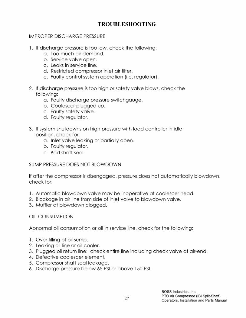
IMPROPER DISCHARGE PRESSURE
1. If discharge pressure is too low, check the following:a. Too much air demand.b. Service valve open.c. Leaks in service line.d. Restricted compressor inlet air filter.e. Faulty control system operation (i.e. regulator).
2. If discharge pressure is too high or safety valve blows, check the following:
a. Faulty discharge pressure switchgauge.b. Coalescer plugged up.c. Faulty safety valve.d. Faulty regulator.
3. If system shutdowns on high pressure with load controller in idle position, check for:
a. Inlet valve leaking or partially open.b. Faulty regulator.c. Bad shaft-seal.
SUMP PRESSURE DOES NOT BLOWDOWN
If after the compressor is disengaged, pressure does not automatically blowdown,check for:
1. Automatic blowdown valve may be inoperative at coalescer head.2. Blockage in air line from side of inlet valve to blowdown valve.3. Muffler at blowdown clogged.
OIL CONSUMPTION
Abnormal oil consumption or oil in service line, check for the following:
1. Over filling of oil sump.2. Leaking oil line or oil cooler.3. Plugged oil return line: check entire line including check valve at air-end.4. Defective coalescer element.5. Compressor shaft seal leakage.6. Discharge pressure below 65 PSI or above 150 PSI.

BOSS Industries, Inc.PTO Air Compressor (IBI Split-Shaft)Operators, Installation and Parts Manual 28
TROUBLESHOOTING
ENGINE LUGGING
If engine does not accelerate or will not maintain full load speed, check thefollowing:
1. Engine problem (refer to engine manual).
2. Compressor discharge pressure too high.
3. Improper load control operation.
4. Engine idle speed set too low.
5. Operating at above maximum altitude rating of compressor.
COALESCER PLUGGING
If the coalescer element has to be replaced frequently because it is plugging up, itis an indication that foreign material may be entering the compressor inlet or thecompressor oil is breaking down.
Compressor oil can break down prematurely for a number or reasons:
1. Extreme operating temperature.
2. Negligence in draining condensate from oil sump.
3. Using the improper type of oil.
4. Dirty oil.
The complete inlet system should be checked for leaks.

29BOSS Industries, Inc.PTO Air Compressor (IBI Split-Shaft)Operators, Installation and Parts Manual
TROUBLESHOOTING
IMPROPER CONTROL OPERATION (ELECTRONIC SPEED CONTROL UNIT)
Consult the wiring diagram and at the end of this manual for assistance with theelectronic speed control program and settings.
IMPROPER CONTROL OPERATION (AIR CYLINDER CONTROL)
1. When service valves are closed and the load controller regulating cylinder does not move to its idle position, check for:
a. Binding load controller lever or push-pull cable, adjust cable or bead chain.
b. A block in the air line between coalescer head and pressure regulator.
c. Faulty discharge pressure regulator.
2. If the load controller regulating cylinder will not move to full speed when there is an air demand, check for:
a. Faulty or improperly set discharge pressure regulator.
b. Binding load controller lever or push-pull cable, adjust cable or bead chain.
c. Broken or loose modulating spring on load controller.
3. If full load speed cannot be obtained, check the following:
a. Load controller “ High” speed adjustment set too low, adjust cable or bead chain.
b. Compressor operating with too high a sump pressure.
c. Load controller modulating spring tension to high.
d. Operating above maximum altitude rating of engine.
4. If after full load speed has been set and difficulty is encountered in setting the idle speed, check the following:
a. Load controller “ Idle” speed adjustment set incorrectly, adjust cable or bead chain.

BOSS Industries, Inc.PTO Air Compressor (IBI Split-Shaft)Operators, Installation and Parts Manual 30
TROUBLESHOOTING
b. Load controller modulating spring tension to low.
c. Faulty regulator.
d. Bad control line hoses.
5. If the engine stalls when air demand is low, check for the following:
a. Idle speed may be set too low, adjust cable or bead chain.
HIGH COMPRESSOR DISCHARGE TEMPERATURE
1. Check compressor oil level. Add oil if required (see Section for oil specifications).
2. Check electric fan and switch.
3. Clean outside of oil cooler.
4. Clean oil system (cooler) internally.

31BOSS Industries, Inc.PTO Air Compressor (IBI Split-Shaft)Operators, Installation and Parts Manual
COMPRESSOR OPERATION
ENGAGING/DISENGAGING
An operating procedure decal is furnished with every PTO Compressor. This decalshould be attached to the dashboard or visor of the truck where it will be visible tothe driver.
Safety circuits have been incorporated into engagement/disengagement of splitshaft PTO that prevents operation of compressor if parking brakes are not activatedor compressor is under load, all air must be relieved from compressor air system.
On manual transmissions a clutch pedal interlock switch is in series with the abovelisted safeties.
The following decal is a sample. Refer to the decal supplied with your unit whenengaging/disengaging.
Sample decal. Refer to the decal supplied with your unit when engaging/disengaging.

BOSS Industries, Inc.PTO Air Compressor (IBI Split-Shaft)Operators, Installation and Parts Manual 32
COMPRESSOR OPERATION
While Boss Industries has built into its compressor system a comprehensive array ofcontrols and indicators to assure you that it is running properly, you will want torecognize and interpret the readings which will call for service or indicate thebeginning of a malfunction. Before engaging the compressor system, read thissection thoroughly. Familiarize yourself with the controls and indicators, theirpurpose, location, and use.

33BOSS Industries, Inc.PTO Air Compressor (IBI Split-Shaft)Operators, Installation and Parts Manual
COMPRESSOR OPERATION
OPERATING CONDITIONS
The following conditions should exist for maximum performance of the PTO/compressor. The truck should be as close to level as possible when operating. Thecompressor will operate on a 15 degree sideward and lengthwise tilt without anyadverse problems. Fluid carryover and/or oil starvation may occur if operatedbeyond this tilt.
NOTE
IF THE COMPRESSOR IS BEING USED TO POWER SANDBALSTING EQUIPMENT,USE A CHECK VALVE DIRECTLY AFTER THE SERVICE VALVE TO PREVENT
BACKFLOW INTO THE SUMP. THIS CHECK VALVE SHOULD HAVE A MAXIMUMPRESSURE DROP RATING OF 2PSIG (13,78kPa)OPERATING AND A CAPACITY
RATING EQUAL TO THE COMPRESSOR.

BOSS Industries, Inc.PTO Air Compressor (IBI Split-Shaft)Operators, Installation and Parts Manual 34
INSTALLATION
SECTION

35BOSS Industries, Inc.PTO Air Compressor (IBI Split-Shaft)Operators, Installation and Parts Manual
INSTALLATION
This air compressor should be installed only by those who have been trained anddelegated to do so and who have read and understood both the operatorsmanual and the installation manual. Failure to follow the instructions, procedures,and safety precautions in these manuals may result in accident and injuries.
Install, use, and operate this air compressor only in full compliance with all pertinentO.S.H.A. requirements and all pertinent Federal, State, and Local codes orrequirements and with Boss Industries, Inc. instructions.
Do not modify this compressor except with written factory approval.
GENERAL
The overall installation of the Boss PTO Air Compressor lends itself well to staging. Byhandling the installation in various stages, the job becomes much easier andefficient. The following sequence should be adhered to when installing a Boss PTOCompressor: All trucks should be road tested prior to installing Boss equipment todetermine if trucks have any prior problems.
1. Disconnect main truck drive line and remove hanger bearing.2. Mount the split-shaft PTO/Compressor unit with BOSS supplied mounting
brackets.3. Connect all drive lines. While waiting for drive lines to be cut, you may advance
to the other steps of installation.4. Install the oil cooler/fan assembly.5. Install the oil sump assembly.6. Install the oil filter.7. Install the instrument panel.8. Install the load controller.9. Install air cleaner.10.Prepare and install the hoses.11.Prepare and install the electric wiring.12. Initial start-up and test.
NOTE
THE FOLLOWING TEXT AND ILLUSTRATION IS FOR A TYPICAL INSTALLATION.DUE TO CHASSIS DESIGN AND APPLICATION, ALTERNATE METHODS MAY BE
USED. IF QUESTIONS ARISE, CONSULT BOSS INDUSTRIES, INC.

BOSS Industries, Inc.PTO Air Compressor (IBI Split-Shaft)Operators, Installation and Parts Manual 36
STAGES OF INSTALLATION
1. DISCONNECT MAIN TRUCK DRIVELINE
Disconnect and remove main driveline and hanger bearingbracket. Proceed to Step 2.
2. MOUNT SPLIT-SHAFT PTO/COMPRESSOR UNIT
Because of the wide variety of chassis arrangements available, these instructionsare general in nature. The mounting brackets are furnished by Boss Industries. Ifanother mounting arrangement is used, make sure it provides the same type ofsupport as suggested here. Follow the procedure explained below for properinstallation.
A. Select a mounting location which will make the PTO with integralcompressor unit readily accessible for maintenance and allows the PTOdriveshaft to be parallel in all planes with the transmission output shaft andrear axle pinion shaft. Truck maintenance (i.e. clutches...) should beconsidered also. All universal joints on front and rear drivelines shouldhave proper operating angles. Be sure to keep at least a minimumoperating angle of 5 degrees. It is a good idea to check drivelines andangles once the truck is completed and carrying a cargo. For moredefinite instruction, consult Boss Industries.
B. Once the PTO is adjusted to provide correct operating angles, slide top L-brackets against frame on both sides, mark 6 - hole centers (3 per side).Drill six (6) .68 DIA. holes (3 - holes per frame rail) and bolt brackets toframe rail with six (6) 5/8”-11 UNC grade 8 bolts. Bolt lengths will vary forthe different frame thickness. Route wiring for the electric shift and switchplate to a desirable location. Mount the switch and plate on the inside ofthe truck cab. Connect the circuit breaker wire to the run side of thetruck’s ignition switch. Clamp or tape all wiring to the frame or to existingwiring to prevent vibration from chafing or damaging the wiring harness.Proceed to Step 3.
IMPORTANT
IF THE U-JOINTS ARE OUT OF PHASE, COMPRESSOR DAMAGE OR PREMATURE U-JOINT FAILURE WILL OCCUR.

37BOSS Industries, Inc.PTO Air Compressor (IBI Split-Shaft)Operators, Installation and Parts Manual
STAGES OF INSTALLATION
3. INSTALLING DRIVELINES
Install the propeller-shafts. Be sure that the drive shaft used is a slip joint design.Frame deflection, temperature deviations, and similar factors may cause apropeller-shaft without a slip joint to produce severe axial loads on bearings,damaging the PTO, transmission, and/or rear axle. Once proper length isestablished, the shafts must be cut and welded. This operation should beperformed by a shop that is knowledgeable of drivelines (consult the driveshaftmanufacturer for proper welding specifications). Before any weld is made, theshafts must be assembled so that all U-joints are in parallel plain and in phase.Make sure the parallel plains are maintained when the shafts are installed in thetruck.
If the chassis is equipped with drum parking brake mounted directly behind thetransmission, the installer is responsible for the installation of a parking brake ontothe rear of the split-shaft. The parking brake installed must meet or exceed thecapabilities of the original equipment transmission parking brake (a parking brakeoption is available from BOSS). The existing parking should not be removed, butshould have the cable disconnected near the brake drum. The existing cableshould be extended to the brake linkage on the rear of the split-shaft. This allowsyou to reuse the existing brake lever inside the cab.
IMPORTANT
MAKE SURE THE DIRVE SHAFT FLANGES ARE ALWAYS PARALLEL AND THEYOKES ARE PROPERLY ALIGNED.
Proceed to Step 4
4a. INSTALL THE OIL COOLER/FAN ASSEMBLY.
The 12 Volt DC motor-driven fan and oil cooler package is suitable for mounting inmany positions in several locations on the vehicle. The fan is a pull-type, pulling airthrough the cooler and past the motor. The motor is designed to run in onedirection (note direction arrow decal on motor). Be sure to connect the wires forproper rotation. The black and white fan motor wire lead is hot. The plain blackwire motor lead is ground.
NOTE
IN SOME CASES A FRONT MOUNT COMPRESSOR OIL COOLER OPTION WILL BEUSED IN PLACE OF THE STANDARD OIL COOLER/FAN ASSEMBLY. IN THIS CASE,
REFER TO THE FRONT MOUNT COOLER ASSEMBLY SECTION ON PAGE 62.

BOSS Industries, Inc.PTO Air Compressor (IBI Split-Shaft)Operators, Installation and Parts Manual 38
STAGES OF INSTALLATION
The best location for the oil cooler package is cantilevered over the top of the truckcab, with the cooling air blowing vertically upwards. The oil cooler will remainclean, and the fan will always work with cool air. A minimum of four inches ofclearance between the oil cooler and the top of the cab is required for proper airflow.
Another common location for the oil cooler/fan assembly is under the truckbetween the frame rails, behind the rear axle, installed so the cooler package willblow the air from the front of the truck toward the rear.
The truck engine muffler may require relocation to keep the exhaust and the heatfrom entering the oil cooler. It must be recognized that under-the-truck mountingof the oil cooler subjects it to road dirt, mud, slush, and ice. Deflectors, shields, orpans can be installed to protect the oil cooler. The shields must not increase thefans discharge air temperature by more than 5° F.
Recirculation of hot air must also be prevented when shielding. When locating thefan on top of cab or under truck, the motor/fan assembly must be on top.
Mounting in the body wall is common in the walk-in van type body. It isrecommended to use louvers on the outside wall to help prevent rain and/or snowfrom entering the body. Sufficient opening in the truck body (i.e. rear doors open..)must be provided for the cooling air. Air flow can be changed in this application topushing instead of pulling if requested. The fan motor has several drain holes.When mounting the package in a wall or behind the frame rail, fan motor leadsshould point down. Boss Industries can supply cooler package mounting hardwarewhen requested (i.e. wall louvers, etc.).
4b. OPTIONAL FRONT MOUNT COOLER
Optional front mount cooler should be installed next to radiator or intercooler. Thismay mean that you have to space the AC condensor out to get clearance. Theremust be sufficient clearance between cores so they can never touch or rub againsteach other. Cooler must be rigidly mounted to the same support that all othercoolers or radiators are mounted to.

39BOSS Industries, Inc.PTO Air Compressor (IBI Split-Shaft)Operators, Installation and Parts Manual
STAGES OF INSTALLATION
5. INSTALL THE OIL SUMP
The PTO oil sump is designed for horizontal mounting only. The vessel is 12 inches indiameter and 22 inches long and comes equipped with mounting bands andbrackets for bolting to the truck frame or other bracketry. Sump mounting bandsare to be located on the mounting brackets. It is important to be sure that thesump tank is level and that the sight glass is level on the center line of tank from endto end. Not centering the sight glass can cause possible over and/or under filling ofthe tank. Also, the air outlet leading to the coalescer should be centered on top.
6. INSTALL COALESCER ASSEMBLY
The head for the spin-on coalescer canister should be located in an area thatallows for easy access to the canister. The head must be mounted so that thecanister is vertical when in place.
NOTE
THE COALESCER HEAD IS DESIGNED FOR AIR FLOW IN ONE DIRECTION ONLY.PRPOER DIRECTION IS INSIDE OUT FLOW THROUGH THE HEAD AND ELEMENT.
Once the head is in place, spin on the coalescer as per the instructions on thecanister itself. The fitting on the bottom of the canister is for the oil return line. Careshould be taken when connecting this line so damage or over torqueing does nottake place. Hold the nut on the bottom of the can stationary with a wrench whiletightening the fitting and hose to the coalescer.
A minimum pressure orifice is built into a hex plug located in the outlet port of thecoalescer head and will automatically maintain the pressure needed for the unit tofunction properly.
The automatic blowdown valve with a muffler is located on the down stream side(outlet side) of the coalescer head. The blowdown valve should remain intact as itwas shipped. The service valve should be removed and placed where it will beused (i.e. at the hose reel inlet). A 3/4” or 1” line (supplied by installer) should thenbe used to connect the coalescer head to the service valve.
A hose fitting, located in the upstream side of the coalescer head, will feed thepressure switch gauge. The air pressure regulator is located on the outlet of thecoalescer head when installing a Generator/Welder.

BOSS Industries, Inc.PTO Air Compressor (IBI Split-Shaft)Operators, Installation and Parts Manual 40
STAGES OF INSTALLATION
7. INSTALL THE OIL FILTER
The oil filter assembly includes a filter head and oil filter canister. When mounting,the oil filter assembly must be in a vertical position and should be located in anarea that makes it serviceable.
8. INSTALL THE INSTRUMENT PANEL
The compact instrument panel comes fully assembled and can be located wheredesired. Keep in mind that hoses and electric wires have to be connected to it.The most common location for mounting has been on, in, or under the dash, on thecab floor on the driver or passenger side protected by the seat support, or on theservice body near the service valve.
Gauge panel can be mounted on the outside of truck if protected from directelements and road debris.
9A. INSTALL ELECTRONIC ENGINE SPEED CONTROL.Refer to the schematic at the end of this manual for your specific electronic speedcontrol wiring installation.
9B INSTALL THE LOAD CONTROLLER (NON ELECTRONIC ENGINES ONLY)
The load controller (Page 53) was designed to work with any engine, gas or diesel,and to be easily installed. Connect the ball chain to the throttle lever at a pointabout 1 1/2” to 2” form the carburetor shaft center. This may require thefabrication of a suitable flat bracket for attachment to the throttle lever. Attach theflexible cable end to the engine (not the frame or other fixed member) using asuitable fabricated bracket. The cable ends that are threaded should bepositioned in the engine speed control bracket slot at the mid point. The other endof the cable at the throttle end bracket should also bepositioned at the mid point of the threads. The location of this attachment pointmust meet this condition: After a 3/8” pull of the ball chain end, the direction ofpull must be 90 degrees to a line through the throttle lever shaft center.
The ball chain must be slack at engine idle or when the compressor is notengaged, adjust at the chain connector. Make certain the ball chain does notbind, hang up, or otherwise cause interference with the normal movement of thethrottle lever while the compressor is not engaged.
Mount the load controller to any convenient point on the truck frame, inner fender,or fire wall, but not on the engine. (Engine speed adjustments for high

41BOSS Industries, Inc.PTO Air Compressor (IBI Split-Shaft)Operators, Installation and Parts Manual
STAGES OF INSTALLATION
and low end can be made at the threaded end of the cable mounted in theengine speed control bracket. Final fine tuning of engine hi and low speeds canbe done at the full speed stop screw and the idle speed stop screw located on theengine speed control bracket.)
10. INSTALL THE AIR CLEANER
The air cleaner kit consists of a heavy-duty 2-stage dry-type air cleaner, suitable forhorizontal mounting, rubber connections, clamps, and a section of flexible tubing(Page 51). Locate the air cleaner at a point where it can draw in cool, clean air. Apreferred location is above the cab. Be sure to check that all connections aresecurely fitted and clamped. Failure to do so could result in dirty air by-passing thefilter and entering into the compressor system.
11. PREPARE AND INSTALL HOSES
The hose kit consists of a generous amount of bulk hose in various sizes and fittings.The fittings were selected for their ease of assembly in the field, without specialtools. A simple four-step procedure is used to make up the hoses:
Step 1. Put hose in vise just tight enough to prevent it from turning. Cut hose square with fine-tooth hacksaw or cut-off wheel. Clean hose with compressed air.
Step 2. Screw socket counterclockwise onto hose until it bottoms. Back off 1/2 turn.
Step 3. Oil nipple threads and screw clockwise into socket and hose, leaving 1/32 to 1/16” clearance between nipple box and socket.
Step 4. Clean assembly by blowing with compressed air.
Install hoses, be sure to route all hoses so that they do not bind or kink.
Avoid hose contact to exhaust piping, muffler, engine manifold, or any other hotsurfaces. Secure hoses with tie-downs or clamps. Inspect hose for possible areaswhere chaffing may occur. It may be necessary to use a protective sleeve on thehose (s) in these areas or to re-route hose. Check that all fittings are tight andsecure.
BOSS Industries, Inc.PTO Air Compressor (IBI Split-Shaft)Operators, Installation and Parts Manual 42
STAGES OF INSTALLATION
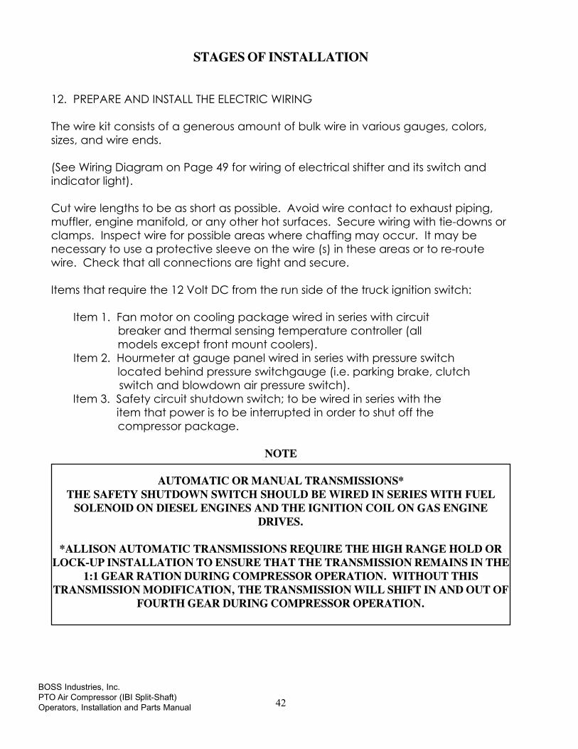
12. PREPARE AND INSTALL THE ELECTRIC WIRING
The wire kit consists of a generous amount of bulk wire in various gauges, colors,sizes, and wire ends.
(See Wiring Diagram on Page 49 for wiring of electrical shifter and its switch andindicator light).
Cut wire lengths to be as short as possible. Avoid wire contact to exhaust piping,muffler, engine manifold, or any other hot surfaces. Secure wiring with tie-downs orclamps. Inspect wire for possible areas where chaffing may occur. It may benecessary to use a protective sleeve on the wire (s) in these areas or to re-routewire. Check that all connections are tight and secure.
Items that require the 12 Volt DC from the run side of the truck ignition switch:
Item 1. Fan motor on cooling package wired in series with circuit breaker and thermal sensing temperature controller (all models except front mount coolers). Item 2. Hourmeter at gauge panel wired in series with pressure switch located behind pressure switchgauge (i.e. parking brake, clutch
switch and blowdown air pressure switch). Item 3. Safety circuit shutdown switch; to be wired in series with the item that power is to be interrupted in order to shut off the compressor package.
NOTE
AUTOMATIC OR MANUAL TRANSMISSIONS*THE SAFETY SHUTDOWN SWITCH SHOULD BE WIRED IN SERIES WITH FUEL
SOLENOID ON DIESEL ENGINES AND THE IGNITION COIL ON GAS ENGINEDRIVES.
*ALLISON AUTOMATIC TRANSMISSIONS REQUIRE THE HIGH RANGE HOLD ORLOCK-UP INSTALLATION TO ENSURE THAT THE TRANSMISSION REMAINS IN THE
1:1 GEAR RATION DURING COMPRESSOR OPERATION. WITHOUT THISTRANSMISSION MODIFICATION, THE TRANSMISSION WILL SHIFT IN AND OUT OF
FOURTH GEAR DURING COMPRESSOR OPERATION.

43BOSS Industries, Inc.PTO Air Compressor (IBI Split-Shaft)Operators, Installation and Parts Manual
STAGES OF INSTALLATION
13. PRESTART-UP INSPECTION CHECKS
This inspection should be done prior to removing truck from bay. Final testing of thesystem, including checking for leaks, is to be done outside.
NOTE
ALL TRUCKS SHOULD BE ROAD TESTED PRIOR TO STARTING INSTALLATION TOISOLATE ANY PREVIOUS TRUCK PROBLEMS.
I. Check order to verify that all items originally ordered have been installed and/orare ready to ship with the truck. This would include any special filters, oils, hoses,etc.
II. Vacuum inside of truck and all areas (including frame and under hood) thathave metal or plastic shavings. Wipe all finger prints off of truck, gauge panel,body, etc.
III. Apply decals to proper location. Make sure that area is cleaned prior toapplying decals. All decals should have a professional appearance uponapplication. Additional decals that need to be applied by the body company,should be placed inside the Boss manual and left in the cab of the truck.
IV. Check all assemblies, clamps, fittings, drivelines, angles, nuts, and bolts to ensurethey are properly secured and/or installed. This includes hoses and wiring;ensure that they are properly tied and secured to the vehicle. This is a verycritical area of the inspection. The vehicle should not be moved until thisinspection has been completed.
V. Record all serial numbers for this installation.A. Truck V.I.N.
B. PTO/Split-shaft information
C. Air-end number
D. Boss serial number
E. Receiver tank number
F. Generator or any other added equipment from Boss
G. Note any special applications relating to specific installations.

BOSS Industries, Inc.PTO Air Compressor (IBI Split-Shaft)Operators, Installation and Parts Manual 44
STAGES OF INSTALLATION
VI. Check all fluid levels. (Position the truck on a level surface so that properamount of fluids can be added.)
A. Fuel- enough for 3 hours of operation.
B. Compressor1. Fill the compressor oil sump (see lubricant section of the operator
and parts section for type of lubricant to use).
2. Capacity is approximately 3.25 gallons.
3. Additional oil may need to be added after test.a) Top off oil level to half the sight glass when finished with
the test.
C. Split-shaft box. Fill gear case to 3/4” square head pipe plug near loweredge of gear case marked OIL LEVEL. DO NOT OVER FILL. Add oil at levelplug or at breather on the top side. Drain case by removing the magneticdrain plug from bottom of the gear case. Use any high-grade, SAE No. 90gear lubricant. Lighter grades (No. 80) are satisfactory if ambienttemperatures are not over 75 degrees F and should be used in extremelycold weather. Oil capacity is about 3 quarts. (For additional informationrefer to Waterous PTO Manual Section).
NOTE
ADD FLUID IF NECESSARY. DO NOT OVER FILL.
D. Lube for driveline.
E. Truck engine oil.
F. Brake fluid.
G. Anti-freeze/coolant.
H. Any other applicable fluids.
45BOSS Industries, Inc.PTO Air Compressor (IBI Split-Shaft)Operators, Installation and Parts Manual
STAGES OF INSTALLATION
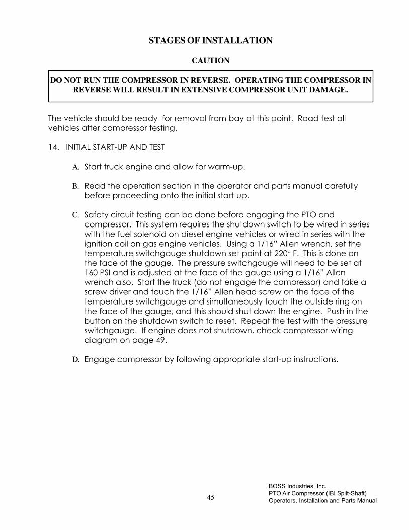
CAUTION
DO NOT RUN THE COMPRESSOR IN REVERSE. OPERATING THE COMPRESSOR INREVERSE WILL RESULT IN EXTENSIVE COMPRESSOR UNIT DAMAGE.
The vehicle should be ready for removal from bay at this point. Road test allvehicles after compressor testing.
14. INITIAL START-UP AND TEST
A. Start truck engine and allow for warm-up.
B. Read the operation section in the operator and parts manual carefullybefore proceeding onto the initial start-up.
C. Safety circuit testing can be done before engaging the PTO andcompressor. This system requires the shutdown switch to be wired in serieswith the fuel solenoid on diesel engine vehicles or wired in series with theignition coil on gas engine vehicles. Using a 1/16” Allen wrench, set thetemperature switchgauge shutdown set point at 220° F. This is done onthe face of the gauge. The pressure switchgauge will need to be set at160 PSI and is adjusted at the face of the gauge using a 1/16” Allenwrench also. Start the truck (do not engage the compressor) and take ascrew driver and touch the 1/16” Allen head screw on the face of thetemperature switchgauge and simultaneously touch the outside ring onthe face of the gauge, and this should shut down the engine. Push in thebutton on the shutdown switch to reset. Repeat the test with the pressureswitchgauge. If engine does not shutdown, check compressor wiringdiagram on page 49.
D. Engage compressor by following appropriate start-up instructions.

BOSS Industries, Inc.PTO Air Compressor (IBI Split-Shaft)Operators, Installation and Parts Manual 46
STAGES OF INSTALLATION
E. Setting engine speeds. (AIR CYLINDER LOAD CONTROLLER ONLY) Toset the load controller, close the service valve and adjust the compressoridle (speed should be approximately 900/1000 RPM). (For vehicles withGenerator/Welder option refer to the Generator/Welder manual). Screwin the idle speed set screw to just touch the load controller arm, thusmaintaining a constant low end. Do not set speed below 900 RPM. Nowadjust the pressure regulator to obtain a sump pressure of 110 PSI. Loosenthe locknut on the regulator adjustment screw and turn the adjustmentscrew clockwise to increase pressure (counter-clockwise to reducepressure). Re-tighten the locknut. Do not set pressure above 110 PSI orbelow 70 PSI. Once regulator setting is done, recheck the idle speed andmake cable adjustments if necessary.
To set the maximum compressor RPM, open the service valve until thesump pressure reads approximately 90 PSI. The maximum compressorRPM is adjusted at the cable end on the engine speed control bracket(see specification section for proper RPM for specific CFM). Recheckthe sump pressure after setting the maximum RPM. Cycle thecompressor from full load to idle by opening and closing the valveslowly several times. Check that the idle and full speed repeat. Unitshould be run for 2 hours (1 hour at maximum compressor RPM and 1hour at compressor idle).
With the unit running at full load, check the operating temperature andoperation of the electrical fan (note: the electrical fan isthermostatically controlled and will turn on only when the oiltemperature has reached approximately 195 degrees). This is also agood time to inspect the system for any leaks.
After the test, disengage the compressor PTO as outlined on the start-up/shutdown decal. The engine should immediately return to truckengine idle (500-600 RPM, see truck manual) with little tendency to overspeed. If truck idle is not obtained, the chain may be to tight. Loosenby one ball at the chain connector and repeat the setting procedurefor the maximum compressor RPM and compressor idle RPM.
With the engine stopped and all engine compartment components inplace, move the engine throttle to full travel several times to makecertain there is no interference with the load controller cable andnormal truck acceleration operation.
Recheck the compressor oil level after the test is completed. Once thecompressor unit oil level has had a chance to level off, top off oil levelto half of the sight glass if required.

47BOSS Industries, Inc.PTO Air Compressor (IBI Split-Shaft)Operators, Installation and Parts Manual
PART NUMBER
&
ILLUSTRATION SECTION
BOSS Industries, Inc.PTO Air Compressor (IBI Split-Shaft)Operators, Installation and Parts Manual 48

49BOSS Industries, Inc.PTO Air Compressor (IBI Split-Shaft)Operators, Installation and Parts Manual

51BOSS Industries, Inc.PTO Air Compressor (IBI Split-Shaft)Operators, Installation and Parts Manual
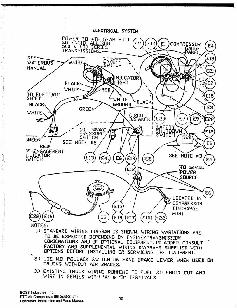
ELECTRICAL SYSTEM
CODE PART NUMBER DESCRIPTION UNIT QTY.E1 300074 GAUGE, HOUR METER EA 1.00E2 300075 SWITCHGAUGE, PRESSURE EA 1.00E3 300076-016 SWITCHGAUGE TEMP W/T WELL, 16 FT. CAP. EA 1.00E4 300077 SWITCH, PRESSURE 15# EA 2.00E5 300079 SWITCH, SHUTDOWN 117 EA 1.00E6 300080 WIRE, 12 GA RED FT 15.00E7 300082 WIRE, 16 GA WHITE FT 5.00E8 300083 WIRE, 16 GA BLUE FT 20.00E9 300084 WIRE, 16 GA YELLOW FT 20.00E10 949012-250 DISCON, FULL INSUL. 1/4” X 12-10 EA 2.00E11 949512-250 DISCON, YELLOW 1/4 X 12-10 EA 1.00E12 949302-014 RING, #10 X 14-18 EA 6.00E13 949302-010 RING, YELLOW #10 X 10-12 EA 8.00E14 949516-250 DISCON, BLUE 1/4” X 16-14 EA 1.00E15 300227 GAUGE, PANEL EA 1.00E16 300474 CONNECTOR, FAN MOTOR EA 1.00E17 300909-025 BREAKER, CIRCUIT 25 AMPS EA 1.00E18 902415-005 TEE, PIPE 1/8 EA 1.00E19 925801-130 NUT, HEX #10-32 UNF EA 2.00E20 949415-014 TERMINAL, BUTT 14-18 EA 1.00E21 960204-012 ELBOW, 1/4 X 1/8 37° FL EA 1.00E22 949306-014 RING, BLUE 3/8” X 14-18 EA 2.00


53BOSS Industries, Inc.PTO Air Compressor (IBI Split-Shaft)Operators, Installation and Parts Manual
INLET SYSTEM
CODE PART NUMBER DESCRIPTION UNIT QTY.I1 300031 CAP, AIR FILTER 6.5 EA 1.00I2 300032 BAND, AIR FILTER MTG. 6.5 EA 2.00I3 300033 CLAMP, AIR INLET 3 EA 6.00I4 300034 SLEEVE, INLET HOSE EA 2.00I5 300071 ELBOW, 3” RUBBER 90° EA 2.00I6 300109 HOSE, INLET 3” GT X FT FT 8.3I7 300917 ASSY, AIR FILTER 6.5 EA 1.00
*REPLACEMENT ELEMENT PART NUMBER 300092


55BOSS Industries, Inc.PTO Air Compressor (IBI Split-Shaft)Operators, Installation and Parts Manual
LOAD CONTROL SYSTEM
CODE PART NUMBER DESCRIPTION UNIT QTY.L1 300054 PLATE, BASE LOAD CONTROLLER EA 1.00L2 *300055 CYLINDER, LARGE LOAD CONTROLLER EA 1.00L3 300057 VALVE, REGULATOR 1/4 EA 1.00L4 *300058 CYLINDER, SMALL LOAD CONTROLLER EA 1.00L5 300059 SPRING, LOAD CONTROLLER EA 1.00L6 300060 LEVER, LOAD CONTROLLER EA 1.00L7 300061 CABLE, LOAD CONTROLLER EA 1.00L8 300062 CLEVIS ASSY, LARGE CYLINDER EA 1.00L9 300063 CLEVIS ASSY, SMALL CYLINDER EA 1.00L10 300064 CHAIN, BEAD EA 1.00L11 300126 HOSE ASSY, 1/4 X 8.5 N.O. EA 2.00L12 300715 VALVE, BLOWDOWN N.O. 1/8 NPT EA 1.00L13 922202-000 NIPPLE, PIPE 1/8 X CLOSE EA 1.00L14 924304-145 NUT, HEX NYLOC GR5 1/4-20 EA 2.00L15 925204-226 NUT, HEX GR5 1/4-20 EA 2.00L16 929104-175 BOLT, HEX GR5 1/4-20 X 1 3/4 EA 2.00L17 938606-071 WASHER, FLAT 3/8” EA 1.00L18 960204-012 ELBOW, 1/8 X 1/4 37° FL EA 2.00L19 960204-025 ELBOW, 1/4 X 1/4 37° FL EA 1.00L20 961604-012 NIPPLE, HEX RED 1/4 X 1/8 EA 1.00L21 961704-012 TEE, M BR 1/4 X 1/8 37° FL EA 1.00L22 961704-025 TEE, M BR 1/4 X 1/4 37° FL EA 1.00L23 964804-025 TEE, M BR 1/4F X 1/4M EA 1.00L24 964904-030 BOLT, HANGER 1/4-20 X 3.0 EA 1.00L25 929104-075 BOLT, HEX GR5 1/4-20 X 3/4” LG EA 1.00
*IF CLEVIS ASSEMBLY IS NEEDED SEPARATELY:L2 CLEVIS IS P/N 300062L4 CLEVIS IS P/N 300063

BOSS Industries, Inc.PTO Air Compressor (IBI Split-Shaft)Operators, Installation and Parts Manual 56
DIS
CH
ARG
E SY
STEM
1000
03

57BOSS Industries, Inc.PTO Air Compressor (IBI Split-Shaft)Operators, Installation and Parts Manual
DISCHARGE SYSTEM100003
PART NUMBER QTY DESCRIPTION ITEM300225 1 EACH SUMP, 12" DISCH. W/PLATE BAFF 1300331 1 EACH HEAD, COALESCER 2300093 1 EACH COALESCER, SPIN-ON ELEMENT 3300605 1 EACH ORIFICE, MIN PRESS 1 1/4 X 1 4907604-030 1 EACH BUSHING, REDUCING 1 X 3/4 5922212-000 2 EACH NIPPLE, .PIPE 3/4 X CLOSE SCH8 6300022-075 1 EACH VALVE, SERVICE - 3/4" VENTED 7922120-110 1 EACH NIPPLE, PIPE 1 1/4 X 11 8902205-025 1 EACH TEE, PIPE RED 1 1/4 X 1/2 X 1 9300023-175 1 EACH VALVE, RELIEF - 1/2 NPT (175#) 10301827 1 EACH VALVE, BLOWDOWN 1/4 N.C. 55502 11922224-000 1 EACH NIPPLE, PIPE 1 1/2 X CLOSE SCH 12902415-060 1 EACH TEE, PIPE 1 1/2" 13300089 1 EACH ADAPTER, 1 1/4 SAE X 1 1/2"NPT 14300090-020 1 EACH CAP, OIL FILL 1-1/4 SAE W/HOLE 15300107 1 EACH SIGHTGLASS, OIL LEVEL 1 1/2 16902203-023 1 EACH TEE, PIPE RED 3/4 X 1/2 X 3/4 17300108 1 EACH PLUG, MAGNETIC 1/2" NPT 18960112-075 1 EACH CONNECTOR, 3/4 JIC X 3/4 MNPT 19901515-060 1 EACH ELBOW, PIPE 1 1/2 20960124-150 1 EACH CONNECTOR,1 1/2JIC X 1 1/2MNPT 21902915-020 1 EACH PLUG, .PIPE 1/2 RECESSED ZINC 22300068 2 EACH BRACKET, RECEIVER TANK 23300021 1 EACH MUFFLER, EXHAUST 1/4 24960204-012 1 EACH ELBOW, 1/4 JIC X 1/8 MNPT 90° 25980704-025 3 EACH ELBOW, 1/4 TB SW X 1/4 MNPT 90° 26300057 1 EACH VALVE, REGULATOR 1/4 27929105-250 2 EACH BOLT, HEX GR5 5/16-18 X 2 1/2 28929806-100 4 EACH BOLT, HEX GR8 3/8-16 X 1 29937806-094 8 EACH WASHER LOC 3/8 GRADE 8 30938206-071 12 EACH WASHER, FLAT 3/8 - GR8 31926006-337 8 EACH NUT, HEX GR8 3/8-16 32929806-150 4 EACH BOLT, HEX GR8 3/8-16 X 1 1/2 33977704-0404 1 EACH TEE, 1/4MNPT X 1/4MNPT X 1/4MN 34300234 2 EACH BAND, SUMP MTG 12 35938205-071 2 EACH WASHER, FLAT 5/16 36925305-283 2 EACH NUT, WHIZ LOCK 5/16-18 37


59BOSS Industries, Inc.PTO Air Compressor (IBI Split-Shaft)Operators, Installation and Parts Manual
COMPRESSOR MOUNTING SYSTEM
CODE PART NUMBER DESCRIPTION UNIT QTY.M1 301331 COMPRESSOR, R.S. DD B101 NON G EA 1.00M2 301085-125 FLANGE, DISCHARGE 1 1/4 EA 1.00M3 929312-040 BOLT, SOCKET HD 12MM X 40MM EA 4.00M4 937512-036 WASHER, HI-COLLAR LOC 12MM EA 4.00M5 970708-075 CONNECTOR, 1/2 BSPP X 3/4 JIC EA 1.00M6 907506-000 PLUG, 14MM BSPP EA 1.00M7 961704-025 TEE, 1/4 X 1/4 X 1/4 EA 1.00M8 902106-020 BUSHING, 1 1/2 X 1/2 EA 2.00M9 301035 BRACKET, IBI S.S. EA 2.00M10 301036 BRACKET, IBI S.S. TOP EA 2.00M11 929810-250 BOLT, HEX GR8 5/8-11 X 2 1/2 EA 11.00M12 928210-112 WASHER, FLAT 5/8 PLATED EA 10.00M13 928010-156 WASHER, LOC 5/8 PLATED EA 10.00M14 926010-559 NUT, HEX GR8 5/8-11 EA 10.00M15 929808-150 BOLT, HEX GR8 1/2-13 X 1 1/2 EA 8.00M16 938200-112 WASHER, FLAT 1/2 EA 8.00M17 938008-125 WASHER, LOC 1/2 EA 8.00M18 300629 VALVE, INLET 90° EA 1.00M19 926102-238 O-RING EA 1.00M20 929310-030 BOLT, SOCKET HD 10MM X 30 EA 4.00M21 937510-024 WASHER, HI-COLLAR 10 EA 4.00M22 300072 SENSOR, FAN EA 1.00M23 970802-012 ADAPTER, 1/8 F TO BRITISH PIPE EA 1.00M24 300721 VALVE, CHECK & OIL RETURN ELBOW EA 1.00M25 302715-060 TEE, SIDEOUTLET 1 1/2 EA 1.00M26 300159-051 PTO, INTEGRAL S.S. TMB 6:1 WO/B EA 1.00M27 922120-030 NIPPLE, PIPE 1 1/4 X 3 EA 1.00M28 907606-050 BUSHING, RED 1 1/2 X 1 1/4 EA 1.00M29 960124-150 CONNECTOR, 1 1/2 X 1 1/2 37° FL EA 1.00M30 960204-025 ELBOW, 1/4 X 1/4 37° FL EA 1.00M31 60057-002 BRAKE, PARKING (OPTIONAL) EA 1.00M32 301176 SHIFTER, ELECTRIC EA 1.00M33 301318 SWITCH, PTO ENGAGEMENT LIGHT EA 1.00M34 929310-030 BOLT, 10MM X 30MM SOCKET HEAD EA 1.00M35 301097 ADAPTER EA 3.00M36 301010 VALVE, INLET CONTROL A.C. 1550 EA 1.00M37 926102-236 O-RING, INLET VALVE A.C. 1550 EA 1.00M38 928206-150 BOLT, GR8 3/8 X 1 1/2 EA 4.00M39 937806-094 WASHER, LOCK 3/8 EA 4.00M40 938206-071 WASHER, FLAT 3/8 EA 4.00M41 300159-053 PTO INTEGRAL S.S. TMB W/AUX EA 1.00
*SEE 60057-007 BILL OF MATERIAL SHOWN ON PAGE 63 FOR PARKING BRAKE PARTS.

BOSS Industries, Inc.PTO Air Compressor (IBI Split-Shaft)Operators, Installation and Parts Manual 60
OIL COOLING SYSTEM100001
300009 1 EACH ASSY, FAN BLADE 18 3-BL 1300012 1 EACH MOTOR, FAN 12VDC 2300013 1 EACH GUARD, FINGER 18 3300014 1 EACH COOLER, OIL 18.6 4300149 2 EACH BRACKET, OIL COOLER VENTURI 18 5925305-283 17 EACH NUT, WHIZ LOCK 5/16-18 6929705-100 33 EACH BOLT, WHIZLOCK GR5 5/16-18 X 1 7960212-075 3 EACH ELBOW, 3/4 JIC X 3/4 MNPT 90° 8961505-140 16 EACH NUT, TINNERMAN - 5/16-18 9300394 1 EACH RING, OIL COOLER (REVISION 0) 10300006 1 EACH VENTURI, OIL COOLER 11300005 1 EACH ELEMENT, OIL FILTER 8060 12300599 1 EACH HEAD, OIL FILTER 13300625 1 EACH BRACKET, COALESCER/OIL 14938204-071 2 EACH WASHER, FLAT 1/4 15929104-075 2 EACH BOLT, .HEX GR5 1/4-20 X 3/4 16938004-062 2 EACH WASHER, .LOC 1/4 17960112-075 1 EACH CONNECTOR, .3/4 JIC X 3/4 MNPT 18300573 1 EACH CLIP, FAN ASSY 1980010 1 EACH KIT, FAN SENSOR/RELAY HARNESS 20300474 1 EACH CONNECTOR, FAN MOTOR 21301755 1 EACH RELAY, POWER WEATHERPRF(NOT SHOWN) 22

61BOSS Industries, Inc.PTO Air Compressor (IBI Split-Shaft)Operators, Installation and Parts Manual
FRONT MOUNT OIL COOLER SYSTEM60023K
925305-283 14 EACH NUT, WHIZ LOCK 5/16-18 1929705-100 14 EACH BOLT, WHIZLOCK GR5 5/16-18 X 1 2960212-075 3 EACH ELBOW, 3/4 JIC X 3/4 MNPT 90° 3300005 1 EACH ELEMENT, OIL FILTER 4300599 1 EACH HEAD, OIL FILTER 5300625 1 EACH BRACKET, COALESCER/OIL 6938204-071 2 EACH WASHER, FLAT 1/4 7929104-075 2 EACH BOLT, .HEX GR5 1/4-20 X 3/4 8938004-062 2 EACH WASHER, .LOC 1/4 9960112-075 1 EACH CONNECTOR, .3/4 JIC X 3/4 MNPT 10301662 1 EACH VALVE, THRML 3/4 3-PORT 11960412-075 1 EACH NIPPLE, .HEX 3/4 MPT X 3/4 MPT 12961712-075 1 EACH TEE, M BR 3/4 X 3/4 X3/4 37ø FL 13300345 1 EACH COOLER, OIL FRONT MOUNT 14301867 2 EACH BRACKET, FR MTG 15902915-030 1 EACH PLUG, PIPE 3/4 RECESSED ZINC 16300756-010 1 EACH FITTING, CRIMP 5/8 X 3/4 17300757-010 1 EACH FTTNG,.RESBL 5/8" ID X 3/4" JIC 18300758-010 15 FOOT HOSE, REUSABLE/CRIMP 5/8
1

BOSS Industries, Inc.PTO Air Compressor (IBI Split-Shaft)Operators, Installation and Parts Manual 62
BILL OF MATERIAL FOR P/N 60057-002
PART NUMBER DESCRIPTION UNIT QTY.301138 BELLCRANK, MOUNTING BRACKET EA 1.00301194 TIE ROD, WAT. BR. LINKAGE 9” TG ONLY EA 1.00301195 YOKE, WAT. BR. LINKAGE 9” TML/TG EA 1.00301196 BELLCRANK, WAT. BR. LINKAGE 9” TML/TG EA 1.00301197 END ADJUSTABLE WAT. BR. LINKAGE 9” TML/TG EA 1.00301198 CAMSHAFT, WAT. BR. LINKAGE 9” TML/TG EA 1.00301199 PIN, CLEVIS WAT. BR. LINKAGE 9” TML/TG EA 1.00301200 PIN, CLEVIS 5/16 X 1 WAT. BR. LINKAGE 9” EA 1.00301201 PIN, CLEVIS 1/2 X 1 27/64 WAT. LINKAGE EA 1.00927102-100 PIN, COTTER 1/8 X 1 EA 1.00927115-075 PIN, COTTER 3/32 X 3/4 EA 2.00300500-048 CABLE, BRAKE 5/16-24 EA 1.00971808-312 CLEVIS, 5/16-24 X 1/2 HOLE X 1/2 GAP EA 1.00301054 DRUM, WAT. PB 9 X 3 EA 1.00300170 STUD, WAT. PB EA 4.00*301272 ASSEMBLY, BRAKE PADS & BACKING EA 1.00
*REPLACEMENT SHOES P/N 301053

63BOSS Industries, Inc.PTO Air Compressor (IBI Split-Shaft)Operators, Installation and Parts Manual
WARRANTYCLAIMS
&
RECOMMENDEDSPARE PARTS
LIST

BOSS Industries, Inc.PTO Air Compressor (IBI Split-Shaft)Operators, Installation and Parts Manual 64
WARRANTY
Boss Industries, Inc.. (BOSS) warrants that this Rotary Screw Compressor unit conforms toapplicable drawings and specifications approved in writing by BOSS. The unit assembly will be freefrom defects in material and workmanship for a period of two (2) years from the date of initialoperation or thirty (30) months from the date of shipment, whichever period first expires. All othercomponents and parts of BOSS manufacture, will be free from defects in material and workmanshipfor a period of one (1) year from the date of initial operation or eighteen (18) months from the date ofshipment, whichever period first expires. If within such period BOSS receives from the Buyerwritten notice of and alleged defect in or nonconformance of the unit, all other components and partsof BOSS manufacture and if in the judgment of BOSS these items do not conform or are found to bedefective in material of workmanship, BOSS will at its option either, (a) furnish a ServiceRepresentative to correct defective workmanship, or )b) upon return of the item F.O.B. BOSSoriginal shipping point, repair or replace the item or issue credit for the replacement item ordered byBuyer, (Defective material must be returned within thirty (30) days of return shipping instructionsfrom BOSS. Failure to do so within specified time will result in forfeiture of claim), or (c) refundthe full purchase price for the item without interest. Factory installed units will also include warrantyon installation for a period of one (1) year. This warranty does not cover damage caused by accident,misuse or negligence. If the compressor unit is disassembled the warranty is void. BOSS’s soleresponsibility and Buyer’s exclusive remedy hereunder is limited to such repair, replacement, orrepayment of the purchase price. Parts not of BOSS manufacture are warranted only to the extentthat they are warranted by the original manufacture. BOSS shall have no responsibility for any costor expense incurred by Buyer from inability of BOSS to repair under said warranty when suchinability is beyond the control of BOSS or caused solely by Buyer.
There are no other warranties, express, statutory or implied, including those ofmerchantability and of fitness of purpose; nor any affirmation of fact or representation
which extends beyond the description of the face hereof.This warranty shall be void and BOSS shall have no responsibility to repair, replace, or repay thepurchase price of defective or damaged parts or components resulting directly or indirectly from theuse of repair or replacement parts not of BOSS manufacture or approved by BOSS or from Buyer’sfailure to store, install, maintain, and operate the compressor according to the recommendationscontained in the Operating and Parts Manual and good engineering practice. The total responsibilityof BOSS for claims, losses, liabilities or damages, whether in contract or tort, arising out of or relatedto its products shall not exceed the purchase price. In no event shall BOSS be liable for any special,indirect, incidental or consequential damages of any charter, including, but not limited to, loss of useof productive facilities or equipment, loss of profits, property damage, expenses incurred in relianceon the performance of BOSS, or lost production, whether suffered by Buyer or any third party.
BOSS INDUSTRIES, INC.720 BOYD BLVD.
LaPORTE, IN 46350(219)324-7776 PHONE
65BOSS Industries, Inc.PTO Air Compressor (IBI Split-Shaft)Operators, Installation and Parts Manual
SUMMARY OF MAIN WARRANTY PROVISIONS
As claims, policies and procedure are governed by the terms of the BOSS Industries, Inc. (BOSS)warranty, it is necessary to outline some of the more important provisions.
The BOSS warranty applies only to new and unused products which, after shipment from the factory,have not been altered, changed, repaired or mistreated in any manner whatsoever. Normalmaintenance items such as lubricants and filters are not warrantable items.
Parts not of BOSS manufacture are warranted only to the extent they are warranted by the originalmanufacturer.
Damage resulting from abuse, neglect, misapplication or overloading of a machine, accessory or partis not covered under warranty.
Deterioration or wear occasioned by chemical and/or abrasive action or excessive heat shall notconstitute defects.
Parts replacement and/or correction of defective workmanship will normally be handled by BOSSIndustries, Inc. or their authorized distributor.
Failure to file a detailed warranty claim/service report for each occurrence of material defect ofdefective workmanship will cause warranty claim to be rejected.
Defective material must be returned within 30 days of receipt of shipping instructions. Failure to doso within specified time will result in forfeiture of claim.
The distributor is responsible for the initial investigation and write up of the warranty claim.
Distributor shall be allowed no more than 30 days from date of repair to file a warranty claim/servicereport.
Warranty for failure of BOSS replacement parts covers the net cost of the party only, not labor andmileage.
The BOSS warranty does not cover diagnostic calls and travel. That is time spent traveling to themachine to analyze the problem and returning with the proper tools and parts to correct the problem.
Boss will deduct from allowable credits for excess freight caused by sender failing to follow returnshipping instructions.
Distributors or end-users automatically deducting the value of a warranty claim from outstandingbalances due and payable to BOSS prior to receiving written notification of BOSS approval of thewarranty claim may be subject to forfeiture of the entire claim.
BOSS Industries, Inc.PTO Air Compressor (IBI Split-Shaft)Operators, Installation and Parts Manual 66
WARRANTY INTRODUCTION
The warranty policy and procedures outlined here within are detailed to provide the claimant with theinformation necessary when filing a warranty claim, and enabling BOSS the ability to serve it’scustomers best.
WARRANTY CLAIMS - GENERAL
An approved claim depends on the following provision:
1. A warranty claim/service report # must be issued by BOSS. (See filing procedures).
2. Failed part must be returned within 30 days, freight prepaid, with receipt of warranty claim/service report.
3. Part is definitely defective.
4. Workmanship is definitely defective.
5. Machine is within warranty period.
6. Machine has been operating within design conditions.
Claims made by distributors must be verified by distributor prior to contracting BOSS.
WARRANTY CLAIMS - FILING PROCEDURES
1. Initiate through purchase order for warranty part or request for credit.
2. Warranty Claims/Service Report will accompany replacement part. When returning failed part tothe factory for warranty credit, fill out all information requested on Warranty Claims/ServiceReport when it is returned to you with replacement part.
3. BOSS will confirm disposition of failed part within 30 days, and or request additionalinformation.
4. Claim acceptance or denial will result in release of a credit or confirmation letter of denial.
5. BOSS will consider each claim on it’s own merit and reserves the right to accept or reject claimrequest. In case of air-ends, these will be returned to the manufacturer for their analysis/input.
6. Send Warranty Claim/Service Report request to:BOSS INDUSTRIES, INC.720 BOYD BLVD.LaPORTE, IN 46350ATTN: WARRANTY CLAIM ENCLOSED

67BOSS Industries, Inc.PTO Air Compressor (IBI Split-Shaft)Operators, Installation and Parts Manual
WARRANTY CLAIMS - PREPARATION OF PART RETURN
Parts returned to the factory must be properly packaged to prevent damage during shipment. Damageto a part as a result of improper handling or packing could be cause for claims disallowance of credit.When addressing the package for shipment, the following information must be on the outside of ortagged clearly to package.
1. Return Goods Authorization.
2. Distributor or end-users return address.
3. Correct factory address.
4. Warranty Claim/Service Report #.
5. Number of packages pertaining to each claim.
NOTE: Our warranty requires that all defective parts be returned to BOSS freight prepaid.Items sent without RGA number will not be accepted.
DAMAGE IN TRANSIT
Do not return damaged merchandise to BOSS, please follow claim procedure.
1. Loss in transit:
The merchandise in our kit or provided in our factory installations has been thoroughly inspected orcarefully installed and tested before leaving our plant. However, regardless of the care taken at thefactory, there is a possibility that damage may occur in shipment. For this reason, it is recommendedthat the unit be carefully inspected for evidence of possible damage or malfunction during the firstfew hours of operation. Responsibility for the safe delivery of the kit or factory installed unit wasassumed by the carrier at the time of shipment. Therefore, claims for loss or damage to the contentsof the kit or factory installed unit should be made upon the carrier.
2. Concealed loss or damage:
Concealed loss or damage means loss or damage which does not become apparent until the kit isunpacked or the factory installed unit is run by the end-user. The contents of the kit or factoryinstalled unit may be damaged due to rough handling while in route to its destination, even thoughthe kit or factory installed unit shows no external damage. When the damage is discovered uponunpacking, make a written request for inspection by the carrier agent within fifteen days of deliverydate. Then file a claim with the carrier since such damage is the carrier’s responsibility.

BOSS Industries, Inc.PTO Air Compressor (IBI Split-Shaft)Operators, Installation and Parts Manual 68
SCREW COMPRESSOR AIR-END EXCHANGE PROGRAM
Factory manufactured air-ends are available on an exchange basis. For current prices andavailability, contact BOSS Industries, Inc. or an authorized BOSS distributor. Prices are F.O.B.shipping point. Prices do not include labor for removal or installation. A repairable trade-in air-endmust be returned freight prepaid within 30 days after shipment of the manufactured air-end. A fivehundred dollar ($500.00 core charge) trade-in allowance will be credited to your account upon returnof the defective trade-in. If no air-end is returned, or the air-end has been disassembled, you will beinvoiced for the difference between exchange price and price without exchange air-end. Exchangedair-ends are warranted for 12 months.

69BOSS Industries, Inc.PTO Air Compressor (IBI Split-Shaft)Operators, Installation and Parts Manual
RECOMMENDED SPARE PARTS LIST
PART NUMBER DESCRIPTION QUANTITY300005 OIL FILTER ELEMENT 1.00
300012 12V-DC FAN MOTOR 1.00
300072 FAN SENSOR 1.00
300086 SHAFT SEAL REPAIR KIT 1.00
300092 AIR FILTER ELEMENT 1.00
300093 SPIN-ON ELEMENT 1.00
300186 INLET VALVE REPAIR KIT 1.00
300187 REGULATOR REPAIR KIT 1.00

BOSS Industries, Inc.PTO Air Compressor (IBI Split-Shaft)Operators, Installation and Parts Manual 70
NOTES