boss 80100 pto air compressor operators ... 80100-ubi-uhbi.pdfpto air compressor operators,...
TRANSCRIPT

BOSS 80100PTO AIR COMPRESSOR
OPERATORS, INSTALLATIONS, ANDPARTS MANUAL
P/N: 30575110/09/2009 MCM


4P/N: 305751
OPERATORS AND PARTS MANUALOPERATION & MAINTENANCE SECTION
TABLE OF CONTENTS
Operation & Maintenance Section
General Arrangement ........................................................................................................................ 6
Specifications ................................................................................................................................... 7
Safety ............................................................................................................................................. 10
Compressor Terminology ................................................................................................................ 16
Description of Components ............................................................................................................. 17
Inspection, Lubrication, and Maintenance ........................................................................................ 21
Troubleshooting .............................................................................................................................. 29
Compressor Operation ................................................................................................................... 32
Parts and Illustration Section ........................................................................................................... 35
Recommended Spare Parts List ...................................................................................................... 46
Service Questionnaire ..................................................................................................................... 47
Installation Section
Instructional Procedures .................................................................................................................. 49
Installation Illustrations .................................................................................................................... 57
Warranty Section
Warranty Information ...................................................................................................................... 66

6P/N: 305751
GENERAL ARRANGEMENT
BOSS Underdeck PTO Compressors are shipped in kit form for field installation. These kitsinclude:
1. Rotary Screw Compressor and Mounting Bracket.
2. Oil Sump with Mounting Brackets.
3. Spin-on Coalescer/Air Manifold Assembly.
4. Compressor Oil Cooler.
5. Air Inlet Filtration System.
6. Hoses and Fittings.
7. All Necessary Safety and Informational Decals.
8. Wiring Harness.
9. Driveshaft Components
10. Parts, Service, Installation, and Maintenance Manual.
BOSS offers factory installation by qualified technicians, as well as a nationwide network ofauthorized distributors for field installations, parts and service.

7P/N: 305751
SPECIFICATIONSBOSS INDUSTRIES 80100-8G UBI COMPRESSOR
*Average hydraulic operating pressure over the cfm range is 2400psig. Motor displ. 1.62 cirPTO Drive Requirements: Engine rotation on PTO. Clockwise rotation looking at compressorshaft.
Typical Applications:- Allison automatic transmission using hot shift PTO’s with engine rotation.- Manual transmissions using Chelsea 442 series PTO’s with adapter gear assemblies to get the required engine rotation.
Typical Installation
DELIVERY @ 110 PSIG CFM 35 45 55 65 75 85 95* 100*Input Speed RPM to
CompressorRPM 1110 1395 1685 1945 2250 2500 2750* 2900*
Hydraulic flow (UHBI Models only)*
GPM 7.8 9.8 11.8 13.6 15.8 17.5 19.2 20.3
Components - Compressor SystemCompressor/Air Inlet
AssemblyReceiver/Sump (TYP.)
Spin - On Element (TYP.)
Remote Cooler/Fan Assembly (TYP.)
Weight (dry) (TYP.)Fluid Capacity (SYS.)
(TYP.)
18" W x 10" H x 23" L
300 pounds
2.50 Gallons
(Overall Dimensions)
10" W x 11" H x 14" L
5" Diameter x 13" L
10" Diameter x 20" L
8P/N: 305751
SPECIFICATIONS
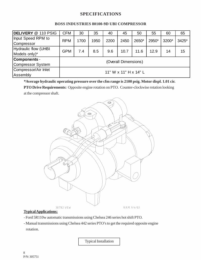
BOSS INDUSTRIES 80100-9D UBI COMPRESSOR
*Average hydraulic operating pressure over the cfm range is 2100 psig. Motor displ. 1.01 cir.PTO Drive Requirements: Opposite engine rotation on PTO. Counter-clockwise rotation lookingat the compressor shaft.
Typical Applications:- Ford 5R110w automatic transmissions using Chelsea 246 series hot shift PTO.- Manual transmissions using Chelsea 442 series PTO’s to get the required opposite engine rotation.
Typical Installation
DELIVERY @ 110 PSIG CFM 30 35 40 45 50 55 60 65Input Speed RPM to Compressor
RPM 1700 1950 2200 2450 2650* 2950* 3200* 3425*
Hydraulic flow (UHBI Models only)*
GPM 7.4 8.5 9.6 10.7 11.6 12.9 14 15
Components - Compressor SystemCompressor/Air Inlet Assembly
(Overall Dimensions)
11" W x 11" H x 14" L
9P/N: 305751
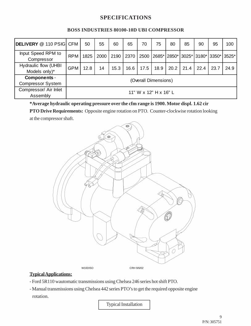
SPECIFICATIONS
BOSS INDUSTRIES 80100-10D UBI COMPRESSOR
*Average hydraulic operating pressure over the cfm range is 1900. Motor displ. 1.62 cirPTO Drive Requirements: Opposite engine rotation on PTO. Counter-clockwise rotation lookingat the compressor shaft.
Typical Applications:- Ford 5R110 wautomatic transmissions using Chelsea 246 series hot shift PTO.- Manual transmissions using Chelsea 442 series PTO’s to get the required opposite engine rotation.
Typical Installation
W10DISO CRH 9/6/02
DELIVERY @ 110 PSIG CFM 50 55 60 65 70 75 80 85 90 95 100
Input Speed RPM to Compressor
RPM 1825 2000 2190 2370 2500 2685* 2850* 3025* 3180* 3350* 3525*
Hydraulic flow (UHBI Models only)*
GPM 12.8 14 15.3 16.6 17.5 18.9 20.2 21.4 22.4 23.7 24.9
Components - Compressor SystemCompressor/ Air Inlet
Assembly
(Overall Dimensions)
11" W x 12" H x 16" L
10P/N: 305751
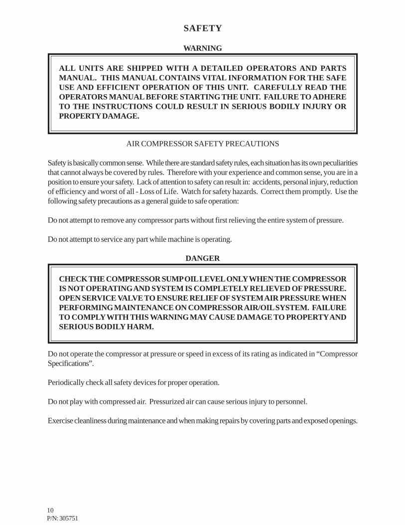
SAFETY
WARNING
AIR COMPRESSOR SAFETY PRECAUTIONS
Safety is basically common sense. While there are standard safety rules, each situation has its own peculiaritiesthat cannot always be covered by rules. Therefore with your experience and common sense, you are in aposition to ensure your safety. Lack of attention to safety can result in: accidents, personal injury, reductionof efficiency and worst of all - Loss of Life. Watch for safety hazards. Correct them promptly. Use thefollowing safety precautions as a general guide to safe operation:
Do not attempt to remove any compressor parts without first relieving the entire system of pressure.
Do not attempt to service any part while machine is operating.
DANGER
Do not operate the compressor at pressure or speed in excess of its rating as indicated in “CompressorSpecifications”.
Periodically check all safety devices for proper operation.
Do not play with compressed air. Pressurized air can cause serious injury to personnel.
Exercise cleanliness during maintenance and when making repairs by covering parts and exposed openings.
ALL UNITS ARE SHIPPED WITH A DETAILED OPERATORS AND PARTSMANUAL. THIS MANUAL CONTAINS VITAL INFORMATION FOR THE SAFEUSE AND EFFICIENT OPERATION OF THIS UNIT. CAREFULLY READ THEOPERATORS MANUAL BEFORE STARTING THE UNIT. FAILURE TO ADHERETO THE INSTRUCTIONS COULD RESULT IN SERIOUS BODILY INJURY ORPROPERTY DAMAGE.
CHECK THE COMPRESSOR SUMP OIL LEVEL ONLY WHEN THE COMPRESSORIS NOT OPERATING AND SYSTEM IS COMPLETELY RELIEVED OF PRESSURE.OPEN SERVICE VALVE TO ENSURE RELIEF OF SYSTEM AIR PRESSURE WHENPERFORMING MAINTENANCE ON COMPRESSOR AIR/OIL SYSTEM. FAILURETO COMPLY WITH THIS WARNING MAY CAUSE DAMAGE TO PROPERTY ANDSERIOUS BODILY HARM.

11P/N: 305751
SAFETY
Do not install a shut-off valve between the compressor and compressor oil sump.
DANGER
Do not disconnect or bypass safety circuit system.
Do not install safety devices other than authorized BOSS INDUSTRIES replacement devices.
Close all openings and replace all covers and guards before operating compressor unit.
Tools, rags, or loose parts must not be left on the compressor or drive parts.
Do not use flammable solvents for cleaning parts.
Keep combustibles out of and away from the Compressor and any associated enclosures.
The owner, lessor, or operator of the Compressor are hereby notified and forewarned that any failure toobserve these safety precautions may result in damage or injury.
BOSS INDUSTRIES expressly disclaims responsibility or liability for any injury or damage caused byfailure to observe these specified precautions or by failure to exercise that ordinary caution and due carerequired when operating or handling the Compressor, even though not expressly specified above.
DO NOT USE BOSS INDUSTRIES COMPRESSOR SYSTEMS TO PROVIDEBREATHING AIR. SUCH USAGE, WHETHER SUPPLIED IMMEDIATELY FROMTHE COMPRESSOR SOURCE, OR SUPPLIED TO BREATHING TANKS FORSUBSEQUENT USE, CAN CAUSE SERIOUS BODILY INJURY.
BOSS INDUSTRIES DISCLAIMS ANY AND ALL LIABILITIES FOR DAMAGE FORLOSS DUE TO PERSONAL INJURIES, INCLUDING DEATH, AND/OR PROPERTYDAMAGE INCLUDING CONSEQUENTIAL DAMAGES ARISING OUT OF ANYBOSS INDUSTRIES COMPRESSORS USED TO SUPPLY BREATHING AIR.
12P/N: 305751
SAFETY
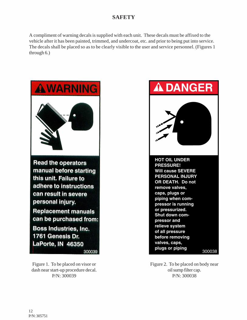
A compliment of warning decals is supplied with each unit. These decals must be affixed to thevehicle after it has been painted, trimmed, and undercoat, etc. and prior to being put into service.The decals shall be placed so as to be clearly visible to the user and service personnel. (Figures 1through 6.)
Figure 1. To be placed on visor ordash near start-up procedure decal.
P/N: 300039
Figure 2. To be placed on body nearoil sump filter cap.
P/N: 300038
13P/N: 305751
SAFETY
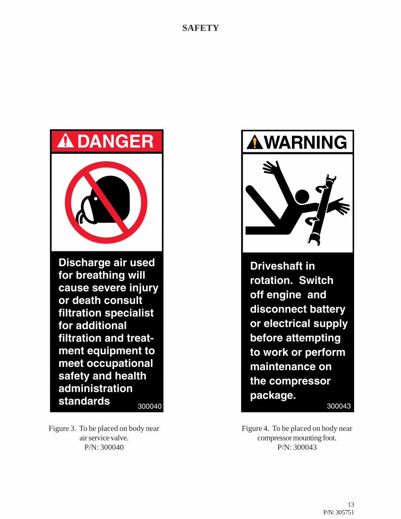
Figure 3. To be placed on body nearair service valve.
P/N: 300040
Figure 4. To be placed on body nearcompressor mounting foot.
P/N: 300043

14P/N: 305751
SAFETY
Figure 5. To be placed near oil coolingfan.
P/N: 300041
Figure 6. To be placed on body airservice valve.P/N: 300042
15P/N: 305751
SAFETY
16P/N: 305751
COMPRESSOR TERMINOLOGY
ATF - Automatic transmission fluid.
AIR/OIL COALESCER - Performs second stage separation of oil from compressed air feeding airtools. Sometimes referred to as the separator element.
AOM - Air Oil Manifold. Consists of coalescer and oil filters. Along with most electrical senders.
BCU - Boss Control Unit. The digital gauge panel that shows system levels and store information.
BIM - Boss Interface Module. Combination of relays, timers, and terminal strips used as the centralwiring point that is chassis specific for ease of installation.
CFM - The volume of compressed air produced expressed as cubic feet of air per minute.
LOAD CONTROLLER - Sometimes referred to as the engine speed control.
OIL SUMP - The first stage of oil separation from compressed air. Also serves as reservoir area forcompressor lubricant and sometimes referred to as the receiver tank.
PSI - Refers to the operating pressure the system is set up at, expressed as pounds per square inch.
SAFETY VALVE - A valve located on the oil sump which opens in case of excessive pressure. Sometimesreferred to as the pop-off or pressure relief valve.
SIDE MOUNT PTO - Power take off gearbox that bolts to the side of the transmission. The PTO inputgear meshes with one of the gears in the vehicle’s transmission. The rotation developed by the enginedrives the transmission which turns the PTO gear box and rotates the PTO output shaft. Special careduring PTO selection should be taken to ensure proper compressor rotation and PTO % is acheived forspecific compressor kit.
ADAPTER GEAR ASSEMBLY: SIDE MOUNT PTO - The adapter gear assembly is to be used onthe 80100-8G model when installed on manual transmissions that require the PTO rotation to be changedfrom “Opposite Engine” rotation to “Engine” rotation.
17P/N: 305751
DESCRIPTION OF COMPONENTS
COMPRESSOR ASSEMBLYThe BOSS INDUSTRIES 80100-8G compressor assembly is a positive displacement, oil flooded, rotaryscrew type unit employing one stage of compression to achieve the desired pressure. Components includea housing (stator), two screws (rotors), bearings, and bearing supports. Power from the engine is transferredto the male rotor through a drive shaft and gears in the gear housing. The female rotor is driven by the malerotor. There are five lobes on the male rotor while the female rotor has six roots. The 80100-9D and80100-10D compressor assemblies are direct drive and do not incorporate the gear housing. Yourcompressor model is selected based on your air flow required and type of transmission mounted PTO thatis used.
PRINCIPLES OF OPERATIONIn operation, two helical grooved rotors mesh to compress air. Inlet air is trapped as the male lobes rolldown the female grooves, pushing trapped air along, compressing it until it reaches the discharge port in theend of the stator and delivers smooth-flowing, pulse-free air to the receiver.
During the compression cycle, oil is injected into the compressor and serves these purposes:1. Lubricates the rotating parts and bearings.2. Serves as a cooling agent for the compressed air.3. Seals the running clearances.
LUBRICATION SYSTEMOil from the compressor oil sump, at compressor discharge pressure, is directed through the oil filter,cooling system, and to the side of the compressor stator, where it is injected into the compressor. At thesame time oil is directed internally to the bearings and shaft seal of the compressor. The oil-laden air is thendischarged back into the sump.
OIL SUMPCompressed, oil-laden air enters the sump from the compressor. As the oil-laden air enters the sump,most of the oil is separated from the air as it passes through a series of baffles and de-fusion plates. The oilaccumulates at the bottom of the sump for recirculation. However, some small droplets of oil remainsuspended in the air and are passed on to the coalescer.
SAFETY VALVEThe pop safety valve is set at 175 PSI and is located at the top of the air/oil sump. This valve acts as abackup to protect the system from excessive pressure that might result from a malfunction.
AIR/OIL COALESCERThe coalescer is self-contained within a spin-on housing and is independent of the sump. When air isdemanded at the service line, it passes through the coalescer which efficiently provides the final stage of oilseparation.
OIL RETURN LINEThe oil that is removed by the coalescer accumulates at the bottom of the can and is returned through an oilreturn line leading to the compressor. The oil return line is 1/4 and goes to elbow hose fitting which islocated at the compressor.

18P/N: 305751
DESCRIPTION OF COMPONENTS
MINIMUM PRESSURE ORIFICEThe minimum pressure orifice is located at the outlet of the coalescer head and serves to maintain aminimum discharge pressure of 65 PSIG in operation, which is required to assure adequate compressorlubrication pressure.
OIL FILTERThe compressor oil filter is the full-flow replaceable element type and has a safety bypass built into it.
COMPRESSOR COOLING SYSTEM (STANDARD)The compressor cooling system consists of an oil cooler remote mounted aerodynamically designed coolingpackage or a cooler mounted in front of the truck’s radiator. Oil temperature is controlled by a thermalswitch on the remote mount cooler package. A thermal valve located down stream of the oil filter is used onthe front mount oil cooler package. The switch or valve maintains compressor oil temperatures in therange of 160º - 200º F.

19P/N: 305751
DESCRIPTION OF COMPONENTS
INSTRUMENTATIONThe BOSS PTO unit incorporates a gauge panel that monitors temperature, hours of operation, oil level,and pressure. It is designed to be mounted inside the cab or in a protected area outside of the cab.
COMPRESSOR DISCHARGE PRESSURE SENDERThis sender indicates the discharge air/oil pressure. Operate compressor within the discharge pressurelimits as indicated in specifications section. The sender ensures high pressure safety shutdown before thesafety relief valve on the sump is discharged, preventing hot pressurized oil spray on the vehicle and/orcompressor components.
HOURMETERThe hourmeter records the total number of operating hours. It serves as a guide in following the recommendedinspection and maintenance schedule. The hourmeter will only run when there is pressure in the system.
COMPRESSOR DISCHARGE AIR/OIL TEMPERATURE SENDERThis sender indicates compressor air discharge temperature. The gauge ensures safety shutdown in caseof excessive operating temperatures, preventing compressor damage.
ELECTRICAL AND SAFETY SYSTEMThe BOSS compressor’s standard electrical system consists of a gauge panel; a remote mount 12 VDCfan package with fan switch and relay assembly (for standard cooling system only); and Boss InterfaceModules (BIM). These components are integrated together to provide a safety shutdown system that isactivated when extreme high temperature or pressure conditions are present. When the temperature orpressure exceeds the maximum set parameter of the BCU sends a signal to “trip” the shutdown relay fromnormally closed to open. This signal will then shut off the engine in vehicles equipped with a CABLE PTOor disengage the PTO in “HOT SHIFT” PTO applications.
ELECTRONIC ENGINE INTERFACEElectronic engine interface for the compressor speed control incorporates several BOSS supplied electricalcomponents that are chassis specific. A chassis specific wiring diagram and BIM is supplied per theinformation application data sheet at the time of the order. Most electronic engines will require programmingby your dealer for the truck chassis.
AUTOMATIC BLOW DOWN VALVEThere is one blow down valve in the compressor system. It is located at the downstream side of thecoalescer head and will automatically bleed the sump to zero pressure when the compressor is disengaged.Blow down time interval takes between 30 to 60 seconds.
CONTROL SYSTEMThe prime component of the compressor control system is the compressor inlet valve. The control systemis designed to match air supply to air demand and to prevent excessive discharge pressure when compressoris at idle. Control of air delivery is accomplished by the inlet valve regulation and modulation as directed bythe discharge pressure regulator.

20P/N: 305751
DESCRIPTION OF COMPONENTS
DISCHARGE PRESSURE REGULATOR VALVEThis valve, located on the coalescer head is used to set the desired discharge pressure within the operatingpressure range. Turning the regulator screw clockwise increases the working pressure, a counterclockwisemovement of the screw reduces the working pressure. This system has a maximum operating pressure of175 psi.
NOTE: Most air tools operating pressure range is between 90 and 125 psi. Operating above thetools recommended pressures will decrease the life of the tool. Higher operating pressure canalso over torque nut and bolts fatiguing the fastener and mating parts. Strictly adhere to tooloperating pressures and torque standards set forth by the tool manufacturer and the specificationsof the equipment that work is being performed on.
INLET VALVEThe compressor inlet valve is a piston operated disc valve that regulates the inlet opening to controlcapacity and serving as a check valve at shutdown.
CONTROL SYSTEM OPERATION (ELECTRONIC ENGINES)The following discussion explains the operation of the control system from a condition of “no load” to acondition of “full capacity” at working pressure. For the working pressure range of your machine, refer toapplicable data in “Specifications”.
The pressure regulator, mounted on the coalescer head, operates as follows:
1. As the demand for air decreases, the receiver pressure rises. When this pressure exceeds theset point of the pressure regulator, the regulator opens sending a secondary pressure signal tothe inlet valve, and in case of two speed, engine speed controls, a timer is activated to slow theengine down to compressor idle. The poppet valve moves towards the valve inlet seat againstthe force of the modulating spring inside the valve. This regulates the opening area of the inletvalve.
2. If the air demand goes to zero, (service valve closed or air dead headed at tool) the inlet valvewill close completely.
3. As the demand for air increases, the secondary pressure signal to the inlet valve is removedand the inlet valve poppet modulates to full open, and the engine returns to the programmedcompressor high RPM.
21P/N: 305751
INSPECTION, LUBRICATION, AND MAINTENANCE
This section contains instructions for performing the inspection, lubrication, and maintenance proceduresrequired to maintain the compressor in proper operating condition. The importance of performing themaintenance described herein cannot be over emphasized.
The periodic maintenance procedures to be performed on the equipment covered by this manual are listedbelow. It should be understood that the intervals between inspections specified are maximum interval.More frequent inspections should be made if the unit is operating in a dusty environment, in high ambienttemperature, or in other unusual conditions. A planned program of periodic inspection and maintenancewill help avoided premature failure and costly repairs. Daily visual inspections should become a routine.
The LUBRICATION AND MAINTENANCE CHART lists serviceable items on this compressor package.The items are listed according to their frequency of maintenance, followed by those items which need only“As Required” maintenance.
The maintenance time intervals are expressed in hours. The hourmeter shows thetotal number of hours your compressor has run. Use the hourmeter readings for determining yourmaintenance schedules. Perform the maintenance at multiple intervals of the hours shown. For example,when the hourmeter shows “100.00,” all items listed under “EVERY 10 HOURS” should be serviced forthe tenth time, and all items under “EVERY 25 HOURS” should be serviced for the fourth time, and theitems under “EVERY 100 HOURS” for the first time.
DANGER
COMPRESSOR MUST BE SHUT DOWN AND COMPLETELY RELIEVED OFPRESSURE PRIOR TO CHECKING FLUID LEVELS. OPEN SERVICE VALVE TOENSURE RELIEF OF SYSTEM AIR PRESSURE. FAILURE TO COMPLY WITH THISWARNING MAY CAUSE DAMAGE TO PROPERTY AND SERIOUS BODILY HARM.

22P/N: 305751
LUBRICATION AND MAINTENANCE CHART
LAVRETNI NOITCA
YLLACIDOIREPGNIRUD
NOITAREPO
morfegnahcynaetoN.gnidaereguagllaevresbO.1evaH.esuacehtenimreteddnagnidaerlamroneht
ehtsi"LAMRON":ETON(.edamsriaperyrassecenralimistagnitareponehwgnidaereguaglausu
).noitarepoyadotyadanosnoitidnoc
SRUOH01YREVEYLIADRO
.levelliorosserpmocehtkcehC.1.retlifriakcehC.2
.skaelriadnaliorofkcehC.3.sehctiwstiucricytefaskcehC.4
SRUOH52YREVEYLHTNOMRO .liorosserpmocmorfretawniarD.1
001YREVESRUOH .tfahsevirdrosserpmocesaerG.1
005YREVE6ROSRUOH
SHTNOM
.retlifliodnaliorosserpmocegnahC.1.egakaelroflaestfahsrosserpmockcehC.2
.spmalcdnasgnittif,gnipipretlifriakcehC.3.stroppusrosserpmockcehC.4
yamlavretniretrohS(.tnemeleretlifriawenllatsnI.5).snoitidnocytsudrednuyrasseceneb
.evlavytefaspmuskcehC.6
0001YREVESRUOH .tnemelegnicselaocegnahC.1
YLLACIDOIREPDERIUQERSARO
.tnemeleretlifrianaelcdnatcepsnI.1fitnemelerecselaocno-nipsecalperdnatcepsnI.2
.yrassecen.snifrelooclionaelcdnatcepsnI.3
NOTE: Compressor oil and filter is to be changed after the first 50 hours of operation. After this,normal intervals are to be followed.

23P/N: 305751
LUBRICANT RECOMMENDATIONS
WARNING
The following are general characteristics for a rotary screw lubricant. Due to the impossibility of establishinglimits on all physical and chemical properties of lubricants which can affect their performance in thecompressor over a broad range of environmental influences, the responsibility for recommending andconsistently furnishing a suitable heavy duty lubricant must rest with the individual supplier if they choosenot to use the recommended BOSS INDUSTRIES rotary screw lubricant. The lubricant supplier’srecommendation must, therefore, be based upon not only the following general characteristics, but alsoupon his own knowledge of the suitability of the recommended lubricant in PTO helical screw type aircompressors operating in the particular environment involved.
CAUTION
IT IS IMPORTANT THAT THE COMPRESSOR OIL BE OF A RECOMMENDEDTYPE AND THAT THIS OIL AS WELL AS THE AIR FILTER, OIL FILTER, ANDCOALESCER ELEMENTS BE INSPECTED AND REPLACED AS STATED IN THISMANUAL.
THE COMBINATION OF A COALESCER ELEMENT LOADED WITH DIRT ANDOXIDIZED OIL PRODUCTS TOGETHER WITH INCREASED AIR VELOCITY AS ARESULT OF THIS CLOGGED CONDITION MAY PRODUCE A CRITICAL POINTWHILE THE MACHINE IS IN OPERATION WHERE IGNITION CAN TAKE PLACEAND COULD CAUSE A FIRE IN THE OIL SUMP.
FAILURE TO COMPLY WITH THIS WARNING MAY CAUSE DAMAGE TOPROPERTY AND SERIOUS BODILY HARM.
MIXING DIFFERENT TYPES OR BRANDS OF LUBRICANTS IS NOTRECOMMENDED DUE TO THE POSSIBILITY OF A DILUTION OF THE ADDITIVESOR A REACTION BETWEEN ADDITIVES OF DIFFERENT TYPES.

24P/N: 305751
LUBRICANT RECOMMENDATIONS
LUBRICANT CHARACTERISTICS1. Flash point 400°F minimum.2. Pour point -40°F.3. Contains rust and corrosion inhibitors.4. Contains foam suppressors.5. Contains oxidation stabilizer.
NOTE
NOTE
DUE TO ENVIRONMENTAL FACTORS THE USEFUL LIFE OF ALL “EXTENDEDLIFE” LUBRICANTS MAY BE SHORTER THAN QUOTED BY THE LUBRICANTSUPPLIER. BOSS INDUSTRIES ENCOURAGES THE USER TO CLOSELYMONITOR THE LUBRICANT CONDITION AND TO PARTICIPATE IN AN OILANALYSIS PROGRAM WITH THE SUPPLIER.
NO LUBRICANT, HOWEVER GOOD AND/OR EXPENSIVE, CAN REPLACEPROPER MAINTENANCE AND ATTENTION. SELECT AND USE IT WISELY.
25P/N: 305751
MAINTENANCE
If some of the maintenance intervals in the schedule outlined in this manual seem to be rather short, it shouldbe considered that one hour’s operation of a compressor is equal to about 40 road miles on an engine.Thus, eight hours operation is equal to 320 road miles, 250 hours is equal to 10,000 road miles, etc.
COMPRESSOR OIL SUMP FILL, LEVEL, AND DRAINBefore adding or changing compressor oil make sure that the sump is completely relieved of pressure. Oilis added at the fill cap on the side of the receiver/sump. A drain plug is provided at the bottom of the sump.The proper oil level, when unit is shut down and has had time to settle, is at the midpoint of the oilsightglass. The truck must be level when checking the oil. DO NOT OVERFILL. The oil sump capacityis given in “Compressor Specifications”.
DANGER
GREASELubricate the compressor drive shaft every time the truck is lubricated or every 100 hours of compressoroperation, whichever comes first.
AIR INTAKE FILTERThe air intake filter is a heavy-duty two-stage dry type high efficiency filter designed to protect the compressorfrom dust and foreign objects.
The filter is equipped with an evacuator cup for continuous dust ejection while operating and when stopped.
Frequency of maintenance of the filter depends on dust conditions at the operating site. The filter elementmust be serviced when clogged (maximum pressure drop for proper operation is 15” H2O).
DO NOT ATTEMPT TO DRAIN CONDENSATE, REMOVE THE OIL LEVEL FILLPLUG, OR BREAK ANY CONNECTION IN THE AIR OR OIL SYSTEM WITHOUTSHUTTING OFF COMPRESSOR AND MANUALLY RELIEVING PRESSURE FROMTHE SUMP. FAILURE TO COMPLY WITH THIS WARNING MAY CAUSE DAMAGETO PROPERTY AND SERIOUS BODILY HARM.
26P/N: 305751
MAINTENANCE
AIR/OIL COALESCERThe air/oil coalescer employs an element permanently housed within a spin-on canister. This is a singlepiece unit that requires replacement when it fails to remove the oil from the discharge air, or pressure dropacross it exceeds 15 PSI. Dirty oil clogs the element and increases the pressure drop across it.
To replace element proceed as follows:
1. Shutdown compressor and wait for complete blow down (zero pressure).2. Turn element counterclockwise for removal (viewing element from bottom).3. Install new rubber seal in head and supply a film of fluid directly to seal.4. Rotate element clockwise by hand until element contacts seal (viewing element from bottom).5. Rotate element approximately one more turn clockwise with band wrench near the top of
element.7. Run system and check for leaks.
WARNING
OIL RETURN LINEThis line originates at the top of the air/oil coalescer head and flows through a clear 1/4” nylon tube to anelbow located at the air-end. This elbow incorporates an oil return line check valve stopping the flow of oilinto the coalescer at shutdown.
DO NOT SUBSTITUTE ELEMENT. USE ONLY A GENUINE BOSS INDUSTRIESREPLACEMENT ELEMENT. THIS ELEMENT IS RATED AT 195 CFM @ 295 PSIWORKING PRESSURE. USE OF ANY OTHER ELEMENT MAY BE HAZARDOUSAND COULD IMPAIR THE PERFORMANCE AND RELIABILITY OF THECOMPRESSOR, POSSIBLY VOIDING THE WARRANTY AND/OR RESULTING INDAMAGE TO PROPERTY AND SERIOUS BODILY HARM.

27P/N: 305751
MAINTENANCE
OIL FILTERThe compressor oil filter is a spin-on, throw away type.
To replace filter proceed as follows:
1. Make sure system pressure is relieved.2. Remove filter by unscrewing from filter head (turn counterclockwise by hand viewing from
bottom) and discard.3. Install a new filter by applying a little oil to the seal and then screw the filter on by hand (turning
it clockwise until hand tight, plus one - third turn viewing from bottom).4. Check for leaks in operation.
WARNING
OIL COOLERThe interior of the oil cooler should be cleaned when the pressure drop across it at full flow exceeds 25PSI. The following procedure has been recommended by the vendor who supplies the cooler:
1. Remove cooler.2. Circulate a suitable solvent to dissolve and remove varnish and sludge.3. Flush generously with BOSS INDUSTRIES compressor lubricant.4. After cooler is reinstalled and compressor is filled with fresh oil, change compressor oil after
50 hours of normal operation.
DO NOT SUBSTITUTE ELEMENT. USE ONLY A GENUINE BOSS INDUSTRIESREPLACEMENT ELEMENT. THIS ELEMENT IS RATED AT 200 PSI WORKINGPRESSURE. USE OF ANY OTHER ELEMENT MAY BE HAZARDOUS AND COULDIMPAIR THE PERFORMANCE AND RELIABILITY OF THE COMPRESSOR,POSSIBLY VOIDING THE WARRANTY AND/OR RESULTING IN DAMAGE TOPROPERTY AND SERIOUS BODILY HARM.
28P/N: 305751
MAINTENANCE
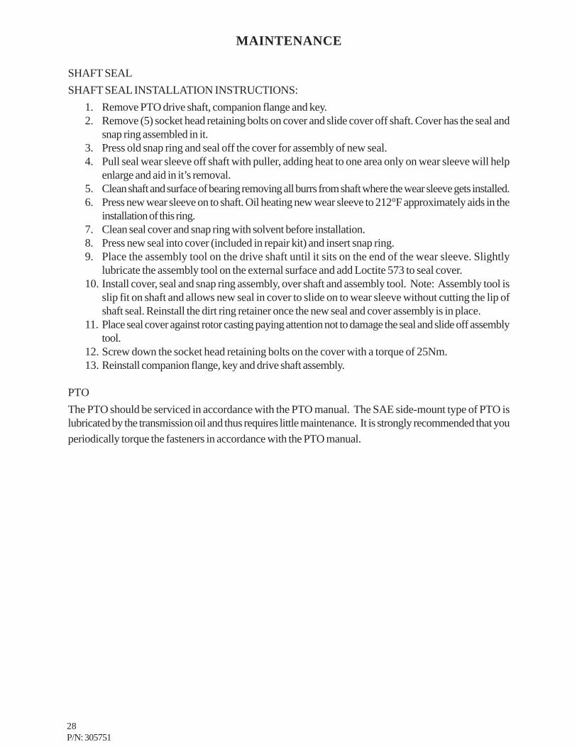
SHAFT SEALSHAFT SEAL INSTALLATION INSTRUCTIONS:
1. Remove PTO drive shaft, companion flange and key.2. Remove (5) socket head retaining bolts on cover and slide cover off shaft. Cover has the seal and
snap ring assembled in it.3. Press old snap ring and seal off the cover for assembly of new seal.4. Pull seal wear sleeve off shaft with puller, adding heat to one area only on wear sleeve will help
enlarge and aid in it’s removal.5. Clean shaft and surface of bearing removing all burrs from shaft where the wear sleeve gets installed.6. Press new wear sleeve on to shaft. Oil heating new wear sleeve to 212°F approximately aids in the
installation of this ring.7. Clean seal cover and snap ring with solvent before installation.8. Press new seal into cover (included in repair kit) and insert snap ring.9. Place the assembly tool on the drive shaft until it sits on the end of the wear sleeve. Slightly
lubricate the assembly tool on the external surface and add Loctite 573 to seal cover.10. Install cover, seal and snap ring assembly, over shaft and assembly tool. Note: Assembly tool is
slip fit on shaft and allows new seal in cover to slide on to wear sleeve without cutting the lip ofshaft seal. Reinstall the dirt ring retainer once the new seal and cover assembly is in place.
11. Place seal cover against rotor casting paying attention not to damage the seal and slide off assemblytool.
12. Screw down the socket head retaining bolts on the cover with a torque of 25Nm.13. Reinstall companion flange, key and drive shaft assembly.
PTOThe PTO should be serviced in accordance with the PTO manual. The SAE side-mount type of PTO islubricated by the transmission oil and thus requires little maintenance. It is strongly recommended that youperiodically torque the fasteners in accordance with the PTO manual.
29P/N: 305751
TROUBLESHOOTING
This section contains instructions for troubleshooting the equipment following a malfunction.
The troubleshooting procedures to be performed on the equipment are listed below. Each symptom oftrouble for a component or system is followed by a list of probable causes of the trouble and suggestedprocedures to be followed to identify the cause.
In general, the procedures listed should be performed in the order in which they are listed, although theorder may be varied if the need is indicated by conditions under which the trouble occurred. In any event,the procedures which can be performed in the least amount of time and with the least amount of removal ordisassembly of parts, should be performed first.
TRUCK ENGINE WILL NOT STARTMost problems in this area will not be connected with the compressor, and should therefore be checkedout with the engine manual.
Manual transmissions require our safety shutdown to shut off the engine in cases of high temperature orpressure. If this occurs the truck can be restarted by waiting 5 seconds for the shutdown relay to release.If the truck still will not restart hold reset button for 5 seconds. If the compressor temperature, pressure,or low oil safety has shut off the engine, the truck should be taken in for service/troubleshooting.
Trucks that have automatic transmissions that use hot shift PTO’s should be wired so the PTO disengagesin the event of a safety shutdown instead of shutting off the truck engine.
UNPLANNED SHUTDOWNWhen the operation of the machine has been interrupted by an unexplained shutdown, take the followingsteps:
1. Disengage PTO immediately.
2. Check the fuel level and truck dash gauges and indications for possible engine problems.3. Check the BCU panel to see if there is an indication for the reason of shutdown. If a light is on
solid, there was a safety shutdown for the corresponding reason. If a light is flashing, therecorresponding sender is wired incorrectly. Fix the identified problem.
4. Check oil cooler for dirt, slush, ice on the fins, or any other obstructions to the cooling air flow.5. If problem is fixed, hold reset button on panel for 5 seconds.

30P/N: 305751
TROUBLESHOOTING
IMPROPER DISCHARGE PRESSURE1. If discharge pressure is too low, check the following:
A. Too much air demand. (Air tools require more air than what the compressor can produce, airtools are free wheeling without resistance.)
B. Service valve wide open to atmosphere.C. Leaks in service line.D. Restricted compressor inlet air filter.E. Faulty control system operation (i.e. regulator is sending a signal to close inlet valve at all
times.)2. If discharge pressure is too high, safety valve blows, or system shuts down on high pressure, check the
following:A. Faulty discharge pressure sender.B. Coalescer plugged up.C. Faulty safety valve.D. Faulty regulator (regulator air pressure signal is not getting to inlet valve)
3. High pressure shutdown at compressor idle:A. Inlet valve leaking or openB. Faulty regulator
SUMP PRESSURE DOES NOT BLOW DOWNIf after the compressor is shutdown, pressure does not automatically blow down, check for:
1. Automatic blow down valve may be inoperative at coalescer head.2. Blockage in air line from side of inlet valve to blow down valve.3. Muffler at blow down clogged.
OIL CONSUMPTIONAbnormal oil consumption or oil in service line, check for the following:
1. Over filling of oil sump.2. Leaking oil lines or oil cooler.3. Plugged oil return line: check entire line, to the compressor.4. Defective coalescer element.5. Compressor shaft seal leakage.6. Discharge pressure below 65 PSI or above 175 PSI.

31P/N: 305751
TROUBLESHOOTING
ENGINE LUGGINGIf engine does not accelerate or will not maintain full load speed, check the following:
1. Engine problem (refer to engine manual).2. Compressor discharge pressure too high.3. Improper compressor speed. (Compressor running at truck idle.)4. Operating above maximum altitude rating of compressor and truck.
COALESCER PLUGGINGIf the coalescer element has to be replaced frequently because it is plugging up, it is an indication thatforeign material may be entering the compressor inlet or the compressor oil is breaking down.
Compressor oil can break down prematurely for a number or reasons.(1) Extreme operating temperature, (2) negligence in draining condensate from oil sump, (3) using theimproper type of oil, (4) dirty oil, (5) oil return line plugged.
The complete air inlet system should be checked for leaks.
HIGH COMPRESSOR DISCHARGE TEMPERATURE1. Check compressor oil level. Add oil if required (see Section for oil specifications).2. Check thermal valve operation. (Front mounting coolers only).3. Clean outside of oil cooler.4. Check if fan is operational.5. Clean oil system (cooler) internally.

32P/N: 305751
COMPRESSOR OPERATION
STARTING/STOPPINGAn operating procedure decal is furnished with every PTO Compressor. The decal should be attached tothe dashboard or visor of the truck where it will be visible to the driver.
The following decal is a sample.
AIR COMPRESSORSStart-Up Procedure1. Set vehicle parking brake and chock wheels.2. Close air service valves. Engine speed control will not engage unless 20 PSI is built up.3. Check compressor oil level; add if low.4. Place transmission in Neutral.5. Engage PTO and depress fuel pedal momentarily until engine speed control takes over.
Shutdown Procedure1. Close air service valves.2. Disengage PTO.
Phone: (219) 324-7776 PN:305647B
33P/N: 305751
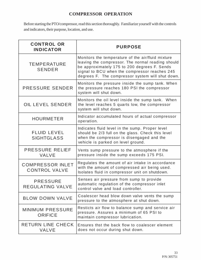
ROLORTNOCROTACIDNI ESOPRUP
ERUTAREPMETREDNES
erutximdiulf/riaehtfoerutarepmetehtsrotinoMdluohsgnidaerlamronehT.rosserpmocehtgnivael
sdneS.Fseerged002ot571yletamixorppaeb542sehcaerrosserpmocehtnehwUCBotlangis
.nwodtuhslliwmetsysrosserpmocehT.Fseerged
REDNESERUSSERPnehW.knatpmusehtedisnierusserpehtsrotinoM
rosserpmocehtISP081sehcaererusserpeht.nwodtuhslliwmetsys
REDNESLEVELLIOnehW.knatpmusehtedisnilevellioehtsrotinoM
rosserpmoceht,wolstrauq5sehcaerleveleht.nwodtuhslliwmetsys
RETEMRUOH rosserpmoclautcafosruohdetalumuccarotacidnI.noitarepo
LEVELDIULFSSALGTHGIS
levelreporP.pmusehtnileveldiulfsetacidnIlevelsihtkcehC.ssalgehtnolluf3/2ebdluohs
ehtdnadegagnesidsirosserpmocehtnehw.dnuorglevelnodekrapsielcihev
FEILERERUSSERPEVLAV
ehtfierehpsomtaehtoterusserppmusstneV.ISP571sdeecxepmusehtedisnierusserp
TELNIROSSERPMOCEVLAVLORTNOC
ecnadroccaniekatniriafotnuomaehtsetalugeR.desugniebriadesserpmocfotnuomaehthtiw
.nwodtuhsnotinurosserpmocnidiulfsetalosI
ERUSSERPEVLAVGNITALUGER
edivorpotpmusmorferusserpriasesneStelnirosserpmocehtfonoitalugercitamotua
.rellortnocdaoldnaevlavlortnoc
EVLAVNWODWOLB pmusehtstnevevlavnwodwolbdaehrecselaoC.nwodtuhstaerehpsomtaehtoterusserp
ERUSSERPMUMINIMECIFIRO
riaecivresdnapmusecnalabotwolfriastcitseRotISP56fomuminimaserussA.erusserp
.noitacirbulrosserpmocniatniam
KCEHCENILNRUTEREVLAV
tnemelerecselaocotwolfkcabehttshtserusnE.nwodtuhsgnirudruccotonseod
COMPRESSOR OPERATION
Before starting the PTO/compressor, read this section thoroughly. Familiarize yourself with the controlsand indicators, their purpose, location, and use.

34P/N: 305751
COMPRESSOR OPERATION
OPERATING CONDITIONS
The following conditions should exist for maximum performance of the PTO/compressor. The truckshould be as close to level as possible when operating. The compressor will operate on a 15 degreesideward and lengthwise tilt without any adverse problems. Fluid carry over and/or oil starvation mayoccur if operated beyond this tilt.
NOTE
NOTE
IF THE COMPRESSOR IS BEING USED TO POWER SANDBLASTINGEQUIPMENT, OR AN AIR STORAGE TANK, USE A CHECK VALVE DIRECTLYAFTER THE MINIMUM PRESSURE ORIFICE TO PREVENT BACKFLOW INTOTHE SUMP. THIS CHECK VALVE SHOULD HAVE A MAXIMUM PRESSURE DROPRATING OF 2 PSIG (13.78kPa) OPERATING AND A CAPACITY RATING EQUAL TOTHE COMPRESSOR.
THE COMPRESSOR SERVICE VALVE SHOULD BE RELOCATED TO THE HOSEREEL INLET OR BE THE CUSTOMERS AIR CONNECTION PORT WHEN A HOSEREEL IS NOT USED. TYPICAL PLUMBING FROM MINIMUM PRESSUREORIFICE SHOULD FLOW IN THE FOLLOWING ORDER:
1. MINIMUM PRESSURE ORIFICE.2. CHECK VALVE.3. AIR TANK (WHEN USED).4. OSHA VALVE5. SERVICE VALVE.6. MOISTURE TRAP/GAUGE/OILER COMBINATION (WHEN USED).

35P/N: 305751
PARTS AND ILLUSTRATION SECTION

36P/N: 305751
HOSE SYSTEM60815
305054 CUT TO LENGTHROUTE FROM 1/2" PORT ON OIL FILTER
TO 1/2" PORT ON SUMP TANK
305227 CUT TO LENGTHROUTE FROM 1 1/4" PORT ON COALESCER
HEAD TO 1 1/4" PORT ON SUMP TANK
WILL USE THE OTHER CRIMP FITTING THAT WAS ATTACHED ON THE ORIGINAL 35' HOSE ASSEMBLY ALONG WITH ONE REUSABLE
USE THIS ASSEMBLY WITH THE 90 DEG CRIMP AT THE COMPRESSOR PORT AND THE STRAIGHT REUSABLE AT THE COOLER OUTLET PORT. 1. CUT HOSE SO ONE ASSEMBLY HAS THE 90° CRIMP FITTING AND ASSEMBLE A REUSABLE FITTING TO THE OTHER END.
2. CUT REMAINING HOSE TO LENGTH FOR THE HOSE RUN FROM THE COOLER INLET TO THE OIL FILTER OUTLET. THIS ASSEMBLY
NOTE: TWO HOSE ASSEMBLIES ARE REQUIRED WITH REMOTE MOUNTED OIL COOLER SYSTEMS.
CUT TO LENGTHROUTE FROM 1" PORT ON COMPRESSOR
TO 1" PORT ON SUMP TANK
ORIGINAL HOSE ASSEMBLY FROM KIT
304785-050
HOSE ASSEMBLY ISTO BE CUT TO LENGTH
304785-050
FITTING.
FIRST CUT
304786-050USE THIS 90° AT
AIR COMPRESSOR
USE THIS 90° AT AIR COMPRESSOR
37P/N: 305751
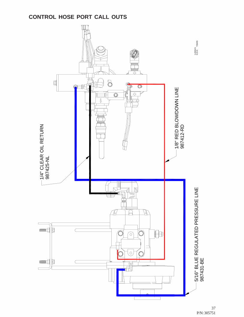
CONTROL HOSE PORT CALL OUTS
1/4"
CLE
AR
OIL
RE
TUR
N98
7425
-NL
5/16
" BLU
E R
EG
ULA
TED
PR
ES
SUR
E LI
NE
9874
31-B
E
1/8"
RE
D B
LOW
DO
WN
LIN
E98
7412
-RD
N.D
.D.
7/
26/0
5IL
2001
21
38P/N: 305751
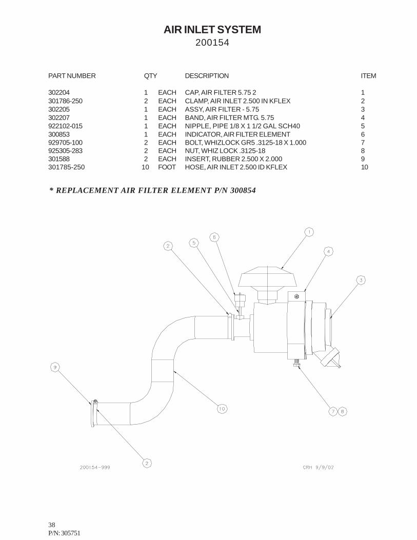
* REPLACEMENT AIR FILTER ELEMENT P/N 300854
AIR INLET SYSTEM200154
PART NUMBER QTY DESCRIPTION ITEM
302204 1 EACH CAP, AIR FILTER 5.75 2 1301786-250 2 EACH CLAMP, AIR INLET 2.500 IN KFLEX 2302205 1 EACH ASSY, AIR FILTER - 5.75 3302207 1 EACH BAND, AIR FILTER MTG. 5.75 4922102-015 1 EACH NIPPLE, PIPE 1/8 X 1 1/2 GAL SCH40 5300853 1 EACH INDICATOR, AIR FILTER ELEMENT 6929705-100 2 EACH BOLT, WHIZLOCK GR5 .3125-18 X 1.000 7925305-283 2 EACH NUT, WHIZ LOCK .3125-18 8301588 2 EACH INSERT, RUBBER 2.500 X 2.000 9301785-250 10 FOOT HOSE, AIR INLET 2.500 ID KFLEX 10

39P/N: 305751
OIL COOLING SYSTEM (REMOTE MOUNT)200313
40P/N: 305751
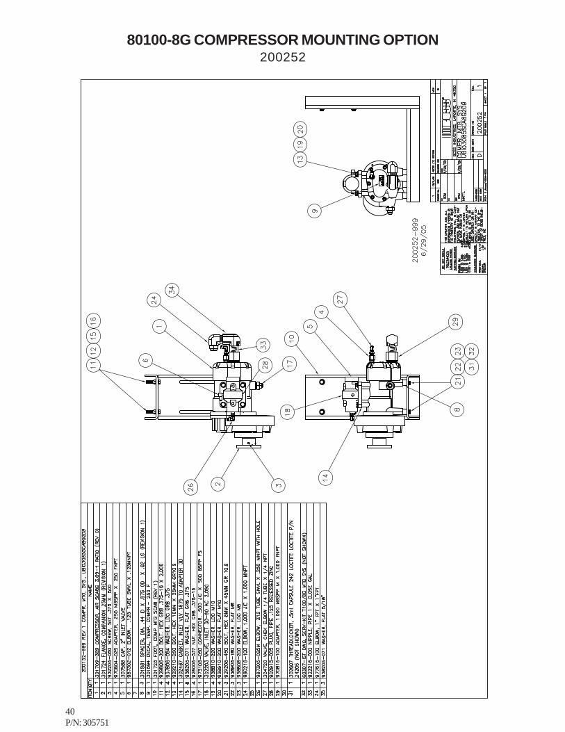
80100-8G COMPRESSOR MOUNTING OPTION200252
41P/N: 305751
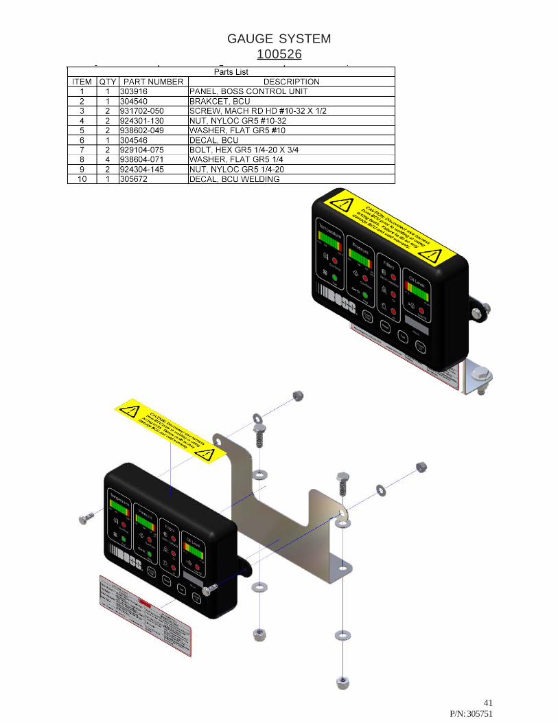
GAUGE SYSTEM100526

42P/N: 305751
BOSS CONTROL UNIT DECAL304546
Phon
e Su
ppor
t : (2
19) 3
24-7
776
w
ww
.bos
sair.
com
TRO
UB
LESH
OO
TIN
GO
verT
emp,
Ove
rPre
ss, o
r Lo
w O
il LE
D is
Fla
shin
g.C
heck
cor
resp
ondi
ng s
ende
r. U
seR
eset
feat
ure.
If p
robl
em s
till
exis
ts, c
all f
or s
uppo
rtO
verT
emp,
Ove
rPre
ss, o
r Lo
w O
il LE
D o
n So
lid.
Shut
dow
n ca
used
by
indi
catin
g LE
D.
Use
Res
et fe
atur
e. If
cau
sepe
rsis
ts, c
all f
or s
uppo
rt.
Filte
r LED
lit.
Filte
r rep
lace
men
t is
need
ed.
See
man
ual f
or fu
rthe
r ins
truc
tion.
Pres
sure
Bar
Gra
ph
flash
ing.
NVM
err
or.
Pane
l nee
ds to
be
repl
aced
.
FEA
TUR
ESC
heck
Oil
But
ton
Dis
play
s oi
l lev
el if
hel
d w
hile
truc
k is
turn
ed o
ff.
Test
But
ton
With
com
pres
sor o
n, w
ill a
ctiv
ate
LED
s an
d re
lays
whe
n he
ld.
Emer
g St
op B
utto
nIf
pres
sed,
shu
tdow
n w
ill b
e ac
tivat
edun
til th
e R
eset
but
ton
is h
eld.
Res
et B
utto
nW
hen
held
for 5
sec
onds
, will
cle
ar
faul
ts a
nd a
larm
s.
AIR
CO
MPR
ESSO
RS
AIR
CO
MPR
ESSO
RS

43P/N: 305751
DISCHARGE SYSTEM200255
27
44P/N: 305751
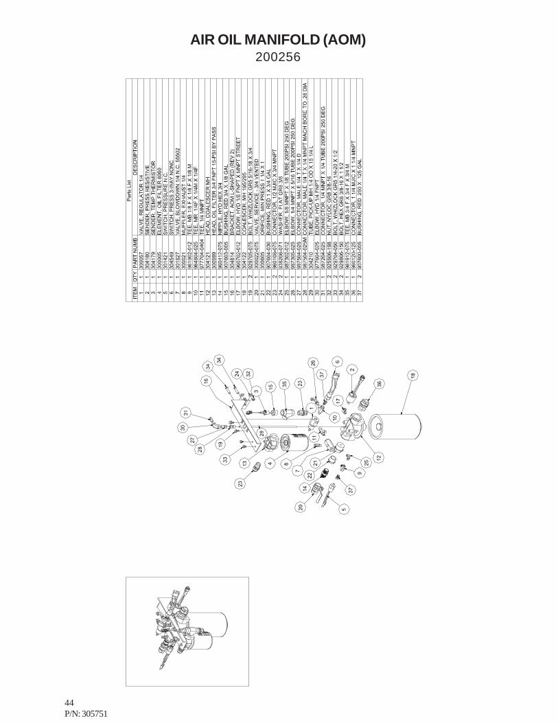
AIR OIL MANIFOLD (AOM)200256

45P/N: 305751
46P/N: 305751
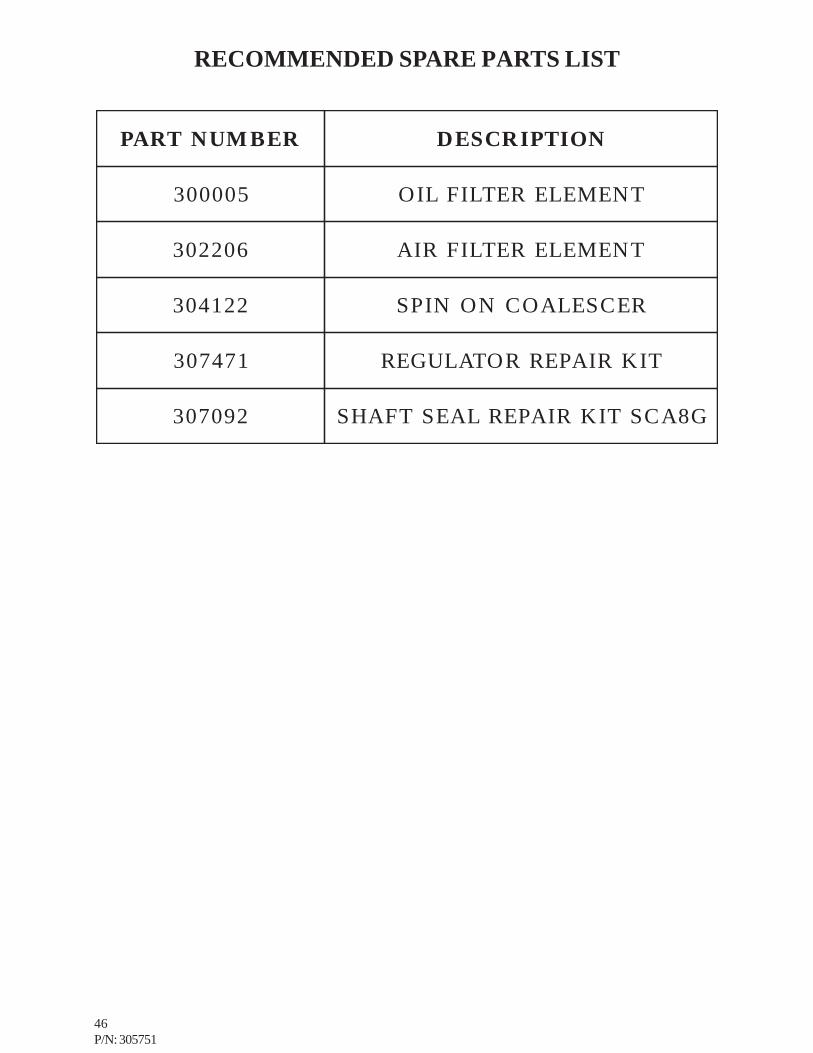
RECOMMENDED SPARE PARTS LIST
REBMUNTRAP NOITPIRCSED
500003 TNEMELERETLIFLIO
602203 TNEMELERETLIFRIA
221403 RECSELAOCNONIPS
174703 TIKRIAPERROTALUGER
290703 G8ACSTIKRIAPERLAESTFAHS

47P/N: 305751
DATE:__________
1. Information given by:______________________________________________2. Information received by:____________________________________________3. Has anyone helped you: Yes______ No______4. Distributor:_____________________________________________________5. End-User:________________________________________________________6. Phone Number:___________________________________________________7. Make and Model for PTO:__________________________________________8. BOSS INDUSTRIES Serial #:_______________________________________9. Make and Model of Engine:_________________________________________10. Engine:________________________________________________________11. Transmission:___________________________________________________12. Nature of Problem:________________________________________________________________________________________________________________________________________________________________________________________________________________________________________________________________________________________________________________________________________________________________________________________________________________________________________________________________________________________________________________________________________________________________________________________________________________________________________________________________________________________________________________________________________________________________________________________________________________________________________________________________13. Engine RPM:_____________________________________________________14. Compressor RPM:________________________________________________15. Action Taken:__________________________________________________________________________________________________________________________________________________________________________________________________________________________________________________________________________________________________________________________________________________________________________________________________________________________________________________________________________________________________________________________________________________________________________________________________________________________________________________________________________________________________________________________________________________________________________________________________________________________________________________________________________________________________________________________________Additional Comments:___________________________________________________________________________________________________________________________________________________________________________________________________________________________________________________________________________________________________________________________________________________________________________________________________________________________________________________________________________________________________________________________________________________________________________________________________________________________________________________________________________________________________________________________________________________________________________________________________________________________________________________________________________________________________________________________________________________________________________________________________________________________________________________________________________________________________________________________________________________________________________________________________________________________________________________________________________________________________________________________________________________________________________________________________________________________________________________________________________________________________________________________________________________________________________________________________________________________________________________________________________________________________________________________________________________________________________________________________________________________________________________________________________________________________
SERVICE QUESTIONNAIRE

48P/N: 305751
INSTALLATION SECTION

49P/N: 305751
Instructional Procedures for the Installation of
BOSS INDUSTRIES 80100 Rotary Screw Air CompressorThis air compressor should be installed only by those who have been trained and delegated to do so andwho have read and understand both the operators’ manual and the installation manual. Failure to followthe instructions, procedures, and safety precautions in this manual may result in accidents and injuries.
Install, use, and operate this air compressor only in full compliance with all pertinent O.S.H.A. requirementsand all pertinent Federal, State, and Local codes or requirements and with BOSS Industries, Inc. instructions.
Do not modify this compressor except with written factory approval.
GENERALThe overall installation of the BOSS PTO air compressor lends itself well to staging. By handling theinstallation in various stages, the job becomes much easier and efficient. The following sequence should beadhered to when installing a BOSS PTO compressor: All trucks should be road tested prior to installingBOSS equipment to determine if trucks have any prior problems.
1. Install the PTO2. Install the compressor and the mounting bracket3. Install the drive shaft4. Install the oil cooler5. Install the oil sump6. Install the Air Oil Manifold7. Install the air cleaner8. Prepare and install the hoses9. Prepare and install the electrical components10. Pre-start up inspection tests11. Initial startup and test
The chassis should be scrutinized for the best location of the compressor and it’s components with the leastamount of relocating equipment previously mounted on the chassis. In most applications, the driver’s sideis the preferred side, due to the exhaust tubing typically located on the right side. However, if there is onlyone PTO opening on the transmission, there is no choice. The compressor and mounting bracket isdesigned for 80100 application of either side. In order to ensure long, trouble-free service of the drive lineto the compressor, the compressor must be located such that the angle requirements of the driveshaft aremet. Direct drive air compressor requires opposite engine rotation on the output shaft of the PTO(counterclockwise looking at the compressor shaft) and typically a low shaft PTO is most suitable, offeringbetter clearances when installing on the (s6-650) zed-f 6-speed manual transmission. Relocate any equipmentthat will cause interference with mounting the compressor and driveline. Geared air compressor requiresrotation on the output shaft of the PTO (clockwise looking at the compressor shaft) and typically a lowshaft PTO is most suitable. Most manual transmissions will require an adapter gear assembly to get theproper rotation to the compressor. When installing on Allison automatic transmissions the Chelsea HotSwitch PTO is recommended. Relocate any equipment that will cause interference with mounting thecompressor and driveline.
50P/N: 305751
1. INSTALL THE PTOThe manual supplied with each PTO gives clear installation instructions. Because of the high level ofengine vibration encountered by the PTO, particular attention must be given to proper tightening of allstuds, nuts, and cap screws. Tighten to PTO manual specifications. The following are 80100 requirementsfor mounting PTO’s:1. Drain the transmission into a clean container.2. Remove the container from the work area and cover to avoid contamination.3. Remove the PTO port access cover from transmission.4. Install PTO mounting studs.5. Temporarily mount PTO gaskets to check backlash and shim accordingly.6. Once backlash has been determined torque all fasteners to their recommended torque specified in
PTO manual.7. Fill transmission and check for leaks. Shift PTO by hand into PTO mode. Run briefly to check
rotation.8. Check continuity of PTO switch with PTO engaged, but not running. Verify that the light comes on.9. Install the PTO cable. The engaging cable must be routed such that it is not in the close proximity
to the engine exhaust pipes, muffler, or sharp edges. Do not kink cable, no bends smaller than 6”radius. The total bends in the cable should not exceed 360º. The shift lever must be installed so itcompletes 100% of it’s required travel. The cable must be mounted very rigidly to the PTO. If aPTO has a forward and reverse gear a mechanical block must be added to the outside or inside ofthe PTO to prevent shifting into the wrong gear. The air compressor requires opposite enginerotation on the output shaft of PTO for direct drive units (clockwise looking at PTO shaft).The air compressor requires engine rotation on the output shaft of PTO for geared units(counterclockwise looking at PTO shaft). Failure to run the compressor in the proper rotation willdamage the compressor and void the warranty.
2. INSTALL COMPRESSOR AND MOUNTING BRACKETThe location on the frame rail is determined by the following factors:1. Does the drive shaft reach the compressor when the drive shaft is assembled using the supplied
components. The maximum length is a function of shaft speed and the true operating angles.2. Can the proper operating angles (see chart) be obtained and are there any obstructions between
the compressor and PTO, i.e. cross-members, transmission bulges, etc.3. Is there clearance to route the compressor intake hose and do you have acceptable ground clearance
in your final compressor location.
The BOSS PTO compressor/mounting bracket can be handled and installed as an assembly. Clamp thecompressor-mounting bracket to the chassis frame. Using an angle finder, angle the compressor such thatthe compressor-input shaft is parallel to the PTO output shaft. Comparing the PTO output shaft to thecompressor input shaft the compressor must be located such that the true operating angles of the drivelineare met The angle of the PTO output shaft can be measured before the end yoke is on the PTO shaft. Theshorter the driveline the smaller the allowable side and top offsets of the two shaft centerlines.Excessive driveline vibration will occur if operating angles are out of their acceptable range for the speedand overall length.
Installation

51P/N: 305751
Installation
3. INSTALL DRIVE SHAFTThe compressor is furnished with a companion flange mounted to the compressor input shaft, which willaccept a 1310 series driveline. The PTO box should have the end yoke installed and the splined slip yokeassembly should attach to the PTO end yoke. A pre-made (welded) tube and tube yoke assembly issupplied in kit. Welding of the slip tube shaft into the tube and yoke assembly is required and should bepreformed at a qualified Spicer driveshaft distributor. The shaft must meet the minimum balance and runout specifications required by Spicer. Ensure the PTO yoke is engaged onto the PTO shaft so the setscrewin the end yoke lines up with the middle of the undercut on PTO shaft. Install the setscrew so it bottoms outin this groove and secure with the supplied mechanics wire. Bolt the flange yoke to the compressor flangewith the four 3/8” x 1 ¼”UNF bolts and lock nuts. After installing the drive shaft, grease the slip yokeassembly with approved driveline grease.
4. INSTALL THE OIL COOLER/FAN ASSEMBLYThe 12 Volt DC motor-driven fan and oil cooler package is suitable for mounting many positions in severallocations on the vehicle. The fan is a pull-type, pulling air through the cooler and past the motor. Themotor is designed to run in one direction (note direction arrow decal on motor). Be sure to connect thewires for proper rotation. The black and white fan motor wire lead is hot.
STAGES OF INSTALLATIONThe best location for the oil cooler package is cantilevered over the top of the truck cab, with the coolingair blowing vertically upwards. The oil cooler will remain clean, and the fan will always work with cool air.A minimum of four inches of clearance between the oil cooler and the top of the cab is required for properair flow.
Another common location for the oil cooler/fan assembly is under the truck between the frame rails, behindthe rear axle, installed so the cooler package will blow the air from the front of the truck toward the rear.
The truck engine muffler may require relocation to keep the exhaust and the heat from entering the oilcooler. It must be recognized that under-the-truck mounting of the oil cooler subjects it to road dirt, mud,slush, and ice. Deflectors, shields, or pans can be installed to protect the oil cooler. The shields must notincrease the fans discharge air temperature by more than 5 degrees F.
Recirculation of hot air must also be prevented when shielding. When locating the fan on top of cab orunder truck, the motor/fan assembly must be on top.
Mounting in the body wall is common in the walk-in van type body. It is recommended to use louvers onthe outside wall to help prevent rain and/or snow from entering the body. Sufficient opening in the truckbody (i.e. rear doors open) must be provided for the cooling air. Air flow can be changed in this applicationto pushing instead of pulling if requested. The fan motor has several drain holes. When mounting thepackage in a wall or behind the frame rail, fan motor leads should point down. Boss Industries can supplycooler package mounting hardware when requested (i.e. wall, louvers, etc.).

52P/N: 305751
4B. INSTALL THE FRONT MOUNTING OIL COOLERDepending on the chassis, removal of the grill or hood may be required to gain access. Install the oil coolerin front of the radiator. Mount the oil cooler in such a manner that the oil cooler does not rub on theradiator or any other component. The cooler must be mounted to the existing truck’s cooler support sothat it can move as one unit or such that when the truck’s existing radiator moves it does not make contactwith the compressor cooler. 80100 brackets are supplied but in some installations these brackets will needto be modified or new mounting hardware will need to be fabricated in house. Some chassis will not havethe necessary room to install the cooler in front of the truck’s radiator and a remote mount style oil coolerwill need to be exchanged for the front mount and it’s related components.
5. INSTALL THE OIL SUMPWhen beginning the sump mount you will want to consider the following before permanently installing;1. The PTO oil sump is designed for horizontal mounting only.2. The sump can be mounted on the inside of the frame rails, or on the outside the frame.3. The final location must allow for easy access to the oil fill and sight glass. Answer the following
questions and the sump mounting will fall into place, How can I plumb the oil fill port so that it isaccessible and will remain level? Where is the body in relationship to the fill and sight glass? Willthe sight glass be visible with the body on? If the oil fill piping is extended, it is better to have thepiping slope down hill towards the sump Vs up hill. Up hill the piping will always show a falsereading at the sight glass. If mounting to the outside of the frame rail will the body interfere with thetank? The vessel is 12 inched in diameter and approximately 22 inches long. Move the tankassembly around to various locations to see what best fits on your specific chassis and body.Locate a position on the chassis frame rail that will allow the oil sump tank to be mounted as closeto the compressor as possible. The sump tank comes equipped with EZ-mounting brackets forbolting to the chassis frame. The EZ-mounting bands are mounted to the frame rail by drilling thetop whole for each band, and then securing the bracket into place with a J-Bolt through the slot.Once both bands are mounted, the sump is then lifted into place. The sump bands are mounted tothe EZ-mounting brackets using the highest possible set of holes that do not cause interferencewith the frame rail. It is important to be sure that the sightglass is level on the centerline of the tankfrom end to end and side to side. Not centering the sightglass can cause possible over or underfilling of the tank, and give an inaccurate reading on the oil level display.
6. INSTALL AIR OIL MANIFOLDThe Air Oil Manifold (AOM) is next to be installed. This system contains most of your senders andswitches, along with coalescer and oil filter. There is a 20” hose in the hose kit that is used for connectingthe head of the coalescer to the sump tank.. There is also a 31” hose supplied to go from the head of theoil filter to the receiver tank.
The AOM should be located in an area that allows for easy access to the two canisters for replacement.The AOM must also be mounted so that the canisters are vertical when in place.
THE COALESCER HEAD IS DESIGNED FOR AIRFLOW IN ONE DIRECTION ONLY.PROPER DIRECTION IS INSIDE OUT FLOW THROUGH THE HEAD AND ELEMENT.
A service valve is installed directly after the minimum pressure orifice. The service valve should be relocatedto an easy access area that allows the operator to control the flow of air. If a hose reel compartment in onthe body the valve should be located before the reel inlet. The automatic blowdown valve and the airpressure regulator are located on the down stream side (outlet side) of the coalescer head.
Installation

53P/N: 305751
7. INSTALL THE AIR CLEANERThe air cleaner kit consists of a heavy-duty, 2-stage, dry type air cleaner, suitable for horizontal mounting,Two clamps, and ten feet of 2 ½” id air intake hose is supplied with each kit. Locate the air cleaner at apoint where it can draw in cool, clean air and that it will reach to the final compressor location. Stay awayfrom areas where the filter can pull in flammable vapors. A preferred location is above the cab. Whenmounting air intake hose try to have minimum number of bends. The intake hose is extremely flexible forease of installation. Be sure to check that all clamps are installed properly and that outside unfiltered aircan not enter without going through the filter. Failure to do so could result in dirty air bypassing the filter andentering into the compressor system.
8. PREPARE AND INSTALL HOSESThe hose kit consists of a generous amount of bulk hose in various sizes and fittings. The fittings wereselected for their ease of assembly in the field, without special tools. A simple five-step procedure is usedto make up the hoses:
Step 1. Determine the hose length.Step 2. Put hose in vise just tight enough to prevent it from turning. Cut hose quare with fine tooth
hacksaw or cut-off wheel. Clean hose with compressed air.Step 3. Screw socket counterclockwise onto hose until it bottoms. Back off ½ turn.Step 4. Oil nipple threads and screw clockwise into socket and hose, leaving 1/32 to 1 1/16” clearance
between nipple box and socket.Step 5. Clean assembly by blowing with compressed air.
Be sure to route all hoses so that they do not bind or kink.Avoid hose contact to exhaust piping, muffler, engine manifold, or any other hot surfaces. Secure hoseswith tie downs or clamps. Inspect hose for possible areas where chaffing may occur. It may be necessaryto use a protective sleeve on the hose(s) in these areas or to re-route hose. Check that all fittings are tightand secure.
KEEP THE CONTROL AIR LINE HOSES AS SHORT AS POSSIBLE AND RUN THEM SOTHEY SLOPE DOWN TOWARD THE AIR COMPRESSOR IN ORDER TO PROMOTEMOISTURE DRAINAGE AT SHUTDOWN, WHICH WILL HELP TO PREVENT ICING INCOLD WEATHER. DO NOT USE OR SUBSTITUTE A DIFFERENT MANUFACTURERSHOSE WITH DIFFERENT MANUFACTURED ENDS/FITTING. IF ADDITIONAL HOSE ISREQUIRED CONTACT THE FACTORY FOR BOSS SPECIFICATIONS.
The 1” discharge line runs from the compressor discharge fitting to the oil sump tank inlet fitting. This is theonly 1” hose assembly required in the basic kit so there should be no confusion as to what ports to hookthe hose assembly up to. There are two hoses made when using a remote mount cooler with the 1/2” hose.One hose runs from the oil injection port on the air compressor to one side of the cooler. The other runsfrom the oil filter head outlet to the other side of the remote mount cooler.
Installation

54P/N: 305751
Installation
9. INSTALLING THE ELECTRICAL WIRING1. Install Sender Connector Harness. This runs from the senders on the Air Oil Manifold to the
location of the Boss Control Unit.2. Install Boss Interface Module (BIM)/prewired relay board in a dry location. Hook up the six pin
connectors from the Sender Harness to the BIM harness.3. Install The Boss Control Unit in weatherproof location. (ex. Rear toolbox, beneath passanger
seat). Install 35-pin connector from BIM harness to back of Boss Control Unit.4. Install the wiring to the PTO as shown in included drawings.5. Install necessary engine and transmission wiring per included drawings.6. Install battery power, ground, and switched ignition to the BIM.

55P/N: 305751
Installation
10. PRE-START-UP INSPECTION CHECKSThis inspection should be done prior to removing truck from bay. Final testing of the system, includingchecking for leaks, is to be done outside.
ALL TRUCKS SHOULD BE ROAD TESTED PRIOR TO STARTING INSTALLATION TOISOLATE ANY PREVIOUS TRUCK PROBLEMS.I. Check sales order to verify that all compressor related items originally ordered have been installed
or are ready to ship with the truck. This would include any special filters, oils, hoses, etc.
II. Vacuum inside of truck and all areas (including frame and underhood) that have metal or plasticshavings. Wipe all fingerprints off truck.
III. Apply decals to proper location. Make sure that the area is cleaned prior to applying decals. Alldecals should have a professional appearance upon application. Additional decals that need to beapplied by the body company should be placed inside the BOSS manual and left in the cab of thetruck.
IV. Check all assemblies, clamps, fittings, drivelines, angles, nuts, and bolts to ensure they are properlytied and secured to the vehicle. This is a very critical area of inspection. The vehicle should not bemoved until this inspection has been completed.
V. Record all serial numbers for this installation.A. Truck V.I.N.B. PTO Model no#C. Air-End Serial NumberD. BOSS Serial NumberE. Receiver Tank Serial NumberF. Note any special applications relating to specific installations.G. Driveshaft should have an identification no# if supplied by a qualified Spicer distributor.H. Record the slopes of the PTO, drive line and the air compressor in the side plane when the truck
is on level ground. Record the total offset in the top plane of the PTO shaft to the compressordrive shaft. Record the center to center distance of the drive shaft installed.
VI. Check all fluid levels (position the truck on a level surface so that proper amount of fluids can beadded).
A. Fuel - enough for three hours of operation.B. Transmission fluid and PTO box.C. Compressor. Fill the compressor oil sump with blue lube. 1) Capacity is approximately 2.5
gallons. Add one quart of blue lube down through the compressor inlet valve. Be careful not todamage the teflon o-ring in the inlet valve when holding open and adding the one quart of bluelube. 2) Additional oil may need to be added after test. 3) Top off oil level to half the sightglasswhen finished with the test.
D. Lube for driveline slip yoke assembly. The u-joint are lube for life bearings and do not require anylube.
E. Brake fluid.F. Anti-freeze – coolant.G. Any other applicable fluids.
The vehicle should be ready for removal from bay at this point. Road test all vehicles after compressortesting.
56P/N: 305751
Installation
11. INITIAL START-UP AND TESTA. Start truck engine and allow for warm-up.B. Read the operation section in the operator and parts manual carefully before proceeding onto the
initial start-up.C. Check indicator lights on the gauge panel. Flashing lights indicate a problem and should be fixed
prior to PTO engagement. Refer to troubleshooting or BCU decal.D. Engage PTO as per the start-up /shutdown decal supplied with the unit. A direction of rotation
arrow is attached to the compressor package above the flange. The shaft must be rotating in thedirection the arrow is pointing. If for any reason this arrow has been removed the correct compressorrotation is opposite engine rotation of output shaft on PTO for direct drive units or clockwise whenlooking at the PTO shaft. The correct compressor rotation is engine rotation of output shaft onPTO for geared units or counterclockwise when looking at the PTO shaft. Check the direction ofrotation by quickly engaging and then disengaging the compressor.
DO NOT RUN THE COMPRESSOR IN A REVERSE ROTATION FOR PERIODSLONGER THAN 5 SECONDS. CONTINUED OPERATION IN THIS MANNER WILLRESULT IN EXTENSIVE COMPRESSOR UNIT DAMAGE.
E. SAFETY CIRCUIT TESTING FOR 80100 COMPRESSOR PACKAGE To test the safetycircuit for units using the Boss Control Unit, engage the compressor PTO. Once the truck hasgone up to speed, press the Emerg Stop button on the BCU. For an automatic transmission, thepto should disengage. If the truck has a manual transmission, the engine should be killed. If thisdoes not occur, immediately shut off the truck and check wiring.

57P/N: 305751
INSTALLATION ILLUSTRATIONS

58P/N: 305751
PTO End Yoke Installation
59P/N: 305751
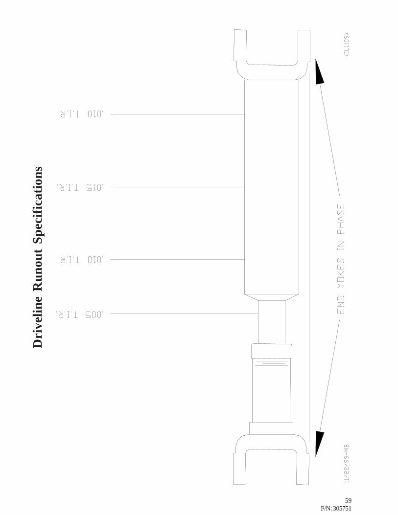
Dri
velin
e R
unou
t Sp
ecifi
catio
ns

60P/N: 305751
Driveline Installation Techniques1. U-JOINT OPERATING ANGLESEvery U-joint that operates at an angle createsvibration.
U-joint operating angles are probably the most commoncause for driveline vibration in vehicles that have beenreworked or that have had auxiliary equipmentinstalled.
When reworking a chassis or installing a newdriveshaft in a vehicle, make sure that you follow thebasic rules that apply to u-joint operating angles, asfollows:1.U-joint operating angles at each end of a shaft should
always be at least 1°.
2.U-joint operating angles on each end of a driveshaftshould always be equal within 1° of each other.
3.U-joint operating angles should not be larger than 3°.If more than 3°, make sure they do not exceed themaximum recommended angles for the RPM atwhich they will be operating.
A u-joint operating angle is the angle that occurs at each end of adriveshaft when the output shaft of the transmission and the inputshaft of the pump are not in line. See figure.
The connecting driveshaft operates with an angle ateach u-joint. It is that angle that creates a vibration.
REDUCING AND CANCELING VIBRATIONA key point to remember about u-joint operating angles:To reduce the amount of vibration, the angles on eachend of a driveshaft should always be SMALL.
To cancel an angle vibration, the u-joint operatingangles need to be EQUAL within 1° at each end of ashaft. See figure.
2. SINGLE PLANE AND COMPOUND U-JOINT OPERATING ANGLESThere are two types of u-joint operating angles, singleplane and compound.
SINGLE PLANESingle plane angles occur when the transmission andpump components are in line when viewed from eitherthe top or side, but not both.
Determine the u-joint operating angle in an applicationwhere the components are in line when viewed fromthe top, but not in line when viewed from the side, is assimple as measuring the slope of the components in theside view, and adding or subtracting those slopes todetermine the angle. See figure.
These angles should be SMALL and equal within 1°.
Determine the u-joint operating angles on a shaft that isstraight when viewed from the side and offset whenviewed from the top requires the use of a special chart(See accompanying chart). In this type of application,the centerlines of the connected components must beparallel when viewed from the top, as shown. Theseangles should also be SMALL and equal within 1°. Seefigure.
Look at the angle chart and note that the smaller theoffset, the smaller the resultant angle.
To reduce the possibility of vibration, keep any offsetbetween connected points to a minimum.

61P/N: 305751
Driveline Installation TechniquesThere are two things which can be done to make certainsingle plane angles are SMALL and EQUAL:
Make sure that the transmission and pump are mounted so that theircenterlines are parallel when viewed from both the side and the top.
Make sure the offset between them is mall in both views.
COMPOUND ANGLESCompound u-joint operating angles occur when thetransmission and pump are not in line when viewed fromboth, the top and side. Their centerlines, however, areparallel in both views. See figure.
TRUE U-JOINT OPERATING ANGLEThe true u-joint operating angle, which must becalculated for each end of the shaft with compoundangles, is a combination of the u-joint operating angle inthe top view, as determined from the chart, and themeasured u-joint operating angle in the side view.
To determine the true u-joint operating angle for one endof a shaft, (compound angle C° in the formula shown infigure below) insert the u-joint operating anglemeasurement obtained in the side view and the u-jointoperating angle obtained from the chart into the formula.
Do the same for the other end of the shaft. Compare theresultant calculated u-joint operating angle for each end.They should be EQUAL within 1°. If they are not, thedriveshaft will vibrate.
3. ELIMINATING COMPOUND ANGLE IN-DUCED VIBRATIONS
Compound u-joint operating angles are one of the mostcommon causes for driveline vibration. To avoid theaseproblems, remember these important considerations:
When setting up an application that requires compound u-jointoperating angles, always keep the centerlines of the transmission andpump parallel in both views.
Always keep the offset between their horizontal and verticalcenterlines small.
NOTECENTERLINES OF TRANSMISSION AND AXLE MUST BEPARALLEL IN BOTH TOP AND SIDE VIEWS TO USE THISMETHOD OF DETERMINING TRUE U-JOINT OPERATINGANGLE. CONTACT BOSS TECHNICAL SUPPORT IF YOUHAVE AN APPLICATION WHICH CANNOT BE INSTALLEDWITH THEIR CENTERLINES PARALLEL.
62P/N: 305751
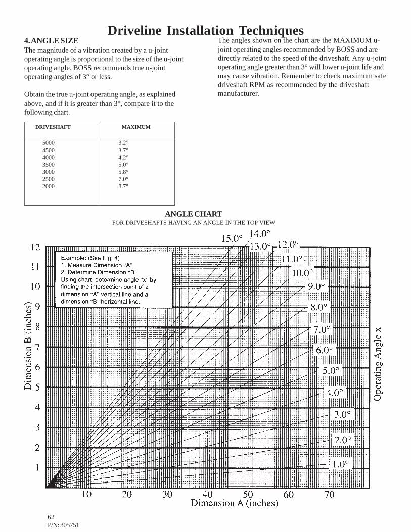
Driveline Installation Techniques4. ANGLE SIZEThe magnitude of a vibration created by a u-jointoperating angle is proportional to the size of the u-jointoperating angle. BOSS recommends true u-jointoperating angles of 3° or less.
Obtain the true u-joint operating angle, as explainedabove, and if it is greater than 3°, compare it to thefollowing chart.
The angles shown on the chart are the MAXIMUM u-joint operating angles recommended by BOSS and aredirectly related to the speed of the driveshaft. Any u-jointoperating angle greater than 3° will lower u-joint life andmay cause vibration. Remember to check maximum safedriveshaft RPM as recommended by the driveshaftmanufacturer.
DRIVESHAFT MAXIMUM
5000 3.2°4500 3.7°4000 4.2°3500 5.0°3000 5.8°2500 7.0°2000 8.7°
ANGLE CHARTFOR DRIVESHAFTS HAVING AN ANGLE IN THE TOP VIEW

63P/N: 305751

64P/N: 305751

65P/N: 305751
WARRANTY SECTION
66P/N: 305751
BOSS INDUSTRIES, INC.1761 Genesis Drive
LAPORTE, IN 46350(800)635-6587 TOLL FREE PHONE
BOSS INDUSTRIES, Inc. warrants that this Rotary Screw Compressor unit conforms to applicabledrawings and specifications approved in writing by BOSS. The unit assembly will be free fromdefects in material and workmanship for a period of two (2) years from the date of initial operationor thirty (30) months from the date of shipment, whichever period first expires. All other componentsand parts of BOSS manufacture, will be free from defects in material and workmanship for aperiod of one (1) year from the date of initial operation or eighteen (18) months from the date ofshipment, whichever period first expires. If within such period BOSS receives from the Buyerwritten notice of and alleged defect in or nonconformance of the unit, all other components andparts of BOSS manufacture and if in the judgment of BOSS these items do not conform or arefound to be defective in material of workmanship, BOSS will at its option either, (a) furnish aService Representative to correct defective workmanship, or (b) upon return of the item F.O.B.BOSS original shipping point, repair or replace the item or issue credit for the replacement itemordered by Buyer, (Defective material must be returned within thirty (30) days of return shippinginstructions from BOSS. Failure to do so within specified time will result in forfeiture of claim), or(c) refund the full purchase price for the item without interest. Factory installed units will alsoinclude warranty on installation for a period of one (1) year. This warranty does not cover damagecaused by accident, misuse or negligence. If the compressor unit is disassembled the warranty isvoid. BOSS’s sole responsibility and Buyer’s exclusive remedy hereunder is limited to such repair,replacement, or repayment of the purchase price. Parts not of BOSS manufacture are warrantedonly to the extent that they are warranted by the original manufacture. BOSS shall have noresponsibility for any cost or expense incurred by Buyer from inability of BOSS to repair undersaid warranty when such inability is beyond the control of BOSS or caused solely by Buyer.
There are no other warranties, express, statutory or implied, including those ofmerchantability and of fitness of purpose; nor any affirmation of fact or representationwhich extends beyond the description of the face hereof.
This warranty shall be void and BOSS shall have no responsibility to repair, replace, or repay thepurchase price of defective or damaged parts or components resulting directly or indirectly fromthe use of repair or replacement parts not of BOSS manufacture or approved by BOSS or fromBuyer’s failure to store, install, maintain, and operate the compressor according to therecommendations contained in the Operating and Parts Manual and good engineering practice.The total responsibility of BOSS for claims, losses, liabilities or damages, whether in contract ortort, arising out of or related to its products shall not exceed the purchase price. In no event shallBOSS be liable for any special, indirect, incidental or consequential damages of any charter, including,but not limited to, loss of use of productive facilities or equipment, loss of profits, property damage,expenses incurred in reliance on the performance of BOSS, or lost production, whether sufferedby Buyer or any third party.
WARRANTY INFORMATION

67P/N: 305751
SUMMARY OF MAIN WARRANTY PROVISIONS
As claims, policies and procedure are governed by the terms of the BOSS INDUSTRIES, Inc. warranty,it is necessary to outline some of the more important provisions.
The BOSS warranty applies only to new and unused products which, after shipment from the factory, havenot been altered, changed, repaired or mistreated in any manner whatsoever. Normal maintenance itemssuch as lubricants and filters are not warrantable items.
Parts not of BOSS manufacture are warranted only to the extent they are warranted by the originalmanufacturer.
Damage resulting from abuse, neglect, misapplication or overloading of a machine, accessory or part is notcovered under warranty.
Deterioration or wear occasioned by chemical and/or abrasive action or excessive heat shall not constitutedefects.
Parts replacement and/or correction of defective workmanship will normally be handled by BOSS or theirauthorized distributor.
Failure to file a detailed warranty claim/service report for each occurrence of material defect of defectiveworkmanship will cause warranty claim to be rejected.
Defective material must be returned within 30 days of receipt of shipping instructions. Failure to do sowithin specified time will result in forfeiture of claim.
The distributor is responsible for the initial investigation and write up of the warranty claim.
Distributor shall be allowed no more than 30 days from date of repair to file a warranty claim/servicereport.
Warranty for failure of BOSS replacement parts covers the net cost of the party only, not labor andmileage.
The BOSS warranty does not cover diagnostic calls and travel. That is time spent traveling to the machineto analyze the problem and returning with the proper tools and parts to correct the problem.
BOSS will deduct from allowable credits for excess freight caused by sender failing to follow returnshipping instructions.
Distributors or end-users automatically deducting the value of a warranty claim from outstanding balancesdue and payable to BOSS prior to receiving written notification of BOSS approval of the warranty claimmay be subject to forfeiture of the entire claim.

68P/N: 305751
WARRANTY/RETURN GOODS INSTRUCTIONS
The warranty/return procedure outlined below is provided to give the claimant the information necessaryto file a warranty/return claim, and enable BOSS INDUSTRIES the ability to best serve its’ customers.
Please see the following instructions to initiate a return:
Contact BOSS INDUSTRIES Returns Department by telephone at 219.324.7776 or via email [email protected]. You may also send a fax at 219.324.7470.
WARRANTY CLAIMS – PREPARATION OF PART RETURN
Parts returned to the factory must be properly packaged to prevent damage during shipment. Damage toa part as a result of improper handling or packing could be cause for denial. When addressing the packagefor shipment, the following information must be on the outside of, or tagged clearly, to the package.
1. Return Goods Authorization #.2. Distributor or end-users return address.3. Correct factory address.4. Number of packages pertaining to each claim.
NOTE: Our warranty requires that all defective parts be returned to BOSS INDUSTRIES freightprepaid. Items sent without RGA number will not be accepted. Unauthorized Returns Will ImmediatelyBe Refused At Dock.
RETURN OR WARRANTY CLAIMS – FILING PROCEDURES
1. Initiate through a purchase order for warranty part or request for credit.2. RGA will accompany replacement part.3. BOSS INDUSTRIES will confirm disposition of failed part within 30 days of receipt and or
request additional information.4. Claim denial will result in issuance of a letter of denial.5. BOSS INDUSTRIES will consider each claim on its’ own merit and reserves the right to accept
or reject claim request. In case of air-ends, these will be returned to the manufacturer for theiranalysis/input.
6. Send Warranty Claim to:BOSS INDUSTRIES, INC.1761 Genesis DriveLaPorte, IN 46350Attn: Returns Dept.
69P/N: 305751
GENERAL
An approved claim depends on the following provision:
1. An RGA # must be issued by BOSS INDUSTRIES. (See filing procedures.)2. Failed part must be returned within 30 days of original invoice date, freight prepaid, with RGA #.3. Part is determined to be defective.4. Workmanship is determined to be defective.5. Machine is within warranty period.6. Machine has been operated within design conditions.
Claims made through distributors must be verified by distributor prior to contacting BOSS INDUSTRIES.
DAMAGE IN TRANSIT
Do not return damaged merchandise to BOSS INDUSTRIES, please follow claim procedure.
1. Loss in transit:The merchandise in our kit or provided in our factory installations has been thoroughly inspectedor carefully installed and tested before leaving our plant. However, regardless of the care taken atthe factory, there is a possibility that damage may occur in shipment. For this reason, it isrecommended that the unit be carefully inspected for evidence of possible damage or malfunctionduring the first few hours of operation. Responsibility for the safe delivery of the kit or factoryinstalled unit was assumed by the carrier at the time of shipment. Therefore, claims for loss ordamage to the contents of the kit or factory installed unit should be made upon the carrier.
2. Concealed loss or damage:Concealed loss or damage means loss or damage, which does not become apparent until the kit isunpacked or the factory-installed unit is run by the end-user. The contents of the kit or factoryinstalled unit may be damaged due to rough handling while in route to its destination, even thoughtthe kit or factory installed unit shows no external damage. When the damage is discovered uponunpacking, make a written request for inspection by the carrier agent within fifteen days of deliverydate. Then file a claim with the carrier since such damage is the carrier’s responsibility.
By following these instructions carefully, we guarantee our full support of your claims, to protect youagainst loss from concealed damage.
3. Visible Loss or DamageAny external evidence of loss or damage must be noted on the Freight Bill or Express Receipt, andsigned by the carrier’s agent. Failure to adequately describe such external evidence of loss, ordamage may result in the carrier refusing to honor a damage claim. The carrier will supply the formrequired to file such a claim.

70P/N: 305751
SCREW COMPRESSOR AIR-END EXCHANGE PROGRAM
Replacement air-ends are available from the factory. For current prices and availability, contact BOSSINDUSTRIES, Inc. or an authorized BOSS INDUSTRIES distributor. Prices are F.O.B. shippingpoint. Prices do not include labor for removal or installation.