3. frame - monosem inc.monosem-inc.com/pdfs/manuals/ng+4/3.5x5.frame.pdftire size = 5.90” x15”...
TRANSCRIPT
TABLE OF CONTENTS_____________________________________________________________________________
1. SAFETY
2. PREPARATION
3. FRAME
4. TRANSMISSION
5. DRIVE
6. ROW UNIT
7. OPTIONAL EQUIPMENT
This is a downloadable version of the manual. A partial download may not contain all pertinent information. Make Sure to read Chapter 1, Safety! Due to ongoing upgrades specifications may change without notice, contact a Monosem Rep for current information.
© Monosem Inc. 2012

This is a downloadable version of the manual. A partial download may not contain all pertinent information. Make Sure to read Chapter 1, Safety! Due to ongoing upgrades specifications may change without notice, contact a Monosem Rep for current information.
© Monosem Inc. 2012
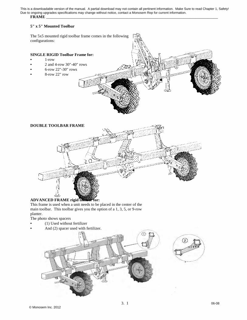
FRAME _____________________________________________________________________________________ 5" x 5" Mounted Toolbar
3. 1 06-08
The 5x5 mounted rigid toolbar frame comes in the following configurations: SINGLE RIGID Toolbar Frame for: • 1-row • 2 and 4-row 30"-40" rows • 6-row 22"-30" rows • 8-row 22" row DOUBLE TOOLBAR FRAME ADVANCED FRAME rigid toolbar for: This frame is used when a unit needs to be placed in the center of the main toolbar. This toolbar gives you the option of a 1, 3, 5, or 9-row planter. The photo shows spacers • (1) Used without fertilizer • And (2) spacer used with fertilizer.
This is a downloadable version of the manual. A partial download may not contain all pertinent information. Make Sure to read Chapter 1, Safety! Due to ongoing upgrades specifications may change without notice, contact a Monosem Rep for current information.
© Monosem Inc. 2012
FRAME _____________________________________________________________________________________ 5" x 5" Mounted Toolbar
3. 2 06-08
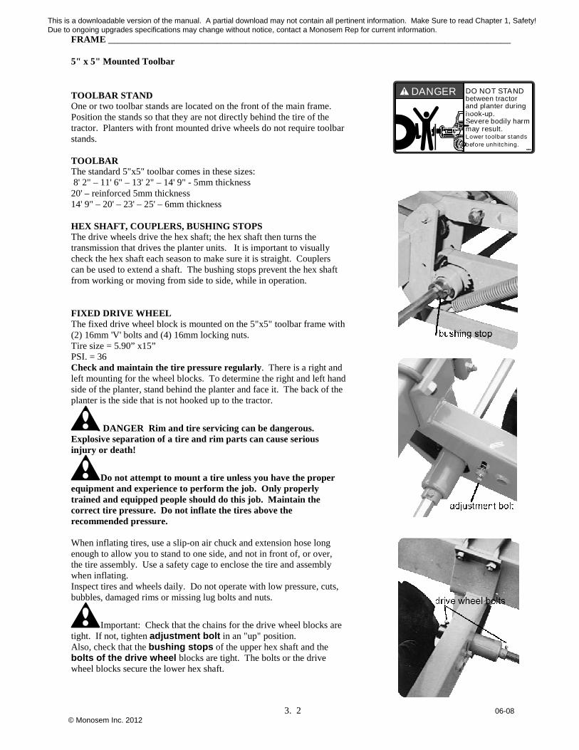
TOOLBAR STAND One or two toolbar stands are located on the front of the main frame. Position the stands so that they are not directly behind the tire of the tractor. Planters with front mounted drive wheels do not require toolbar stands. TOOLBAR The standard 5"x5" toolbar comes in these sizes: 8' 2" – 11' 6" – 13' 2" – 14' 9" - 5mm thickness 20' – reinforced 5mm thickness 14' 9" – 20' – 23' – 25' – 6mm thickness HEX SHAFT, COUPLERS, BUSHING STOPS The drive wheels drive the hex shaft; the hex shaft then turns the transmission that drives the planter units. It is important to visually check the hex shaft each season to make sure it is straight. Couplers can be used to extend a shaft. The bushing stops prevent the hex shaft from working or moving from side to side, while in operation. FIXED DRIVE WHEEL The fixed drive wheel block is mounted on the 5"x5" toolbar frame with (2) 16mm 'V' bolts and (4) 16mm locking nuts. Tire size = 5.90” x15” PSI. = 36 Check and maintain the tire pressure regularly. There is a right and left mounting for the wheel blocks. To determine the right and left hand side of the planter, stand behind the planter and face it. The back of the planter is the side that is not hooked up to the tractor.
DANGER Rim and tire servicing can be dangerous. Explosive separation of a tire and rim parts can cause serious injury or death!
Do not attempt to mount a tire unless you have the proper equipment and experience to perform the job. Only properly trained and equipped people should do this job. Maintain the correct tire pressure. Do not inflate the tires above the recommended pressure. When inflating tires, use a slip-on air chuck and extension hose long enough to allow you to stand to one side, and not in front of, or over, the tire assembly. Use a safety cage to enclose the tire and assembly when inflating. Inspect tires and wheels daily. Do not operate with low pressure, cuts, bubbles, damaged rims or missing lug bolts and nuts.
Important: Check that the chains for the drive wheel blocks are tight. If not, tighten adjustment bolt in an "up" position. Also, check that the bushing stops of the upper hex shaft and the bolts of the drive wheel blocks are tight. The bolts or the drive wheel blocks secure the lower hex shaft.
DO NOT STANDbetween tractorand planter duringhook-up.Severe bodily harmmay result.Lower toolbar standsbefore unhitching.
DANGER
This is a downloadable version of the manual. A partial download may not contain all pertinent information. Make Sure to read Chapter 1, Safety! Due to ongoing upgrades specifications may change without notice, contact a Monosem Rep for current information.
© Monosem Inc. 2012

FRAME _____________________________________________________________________________________ 5" x 5" Mounted Toolbar
3. 3 06-08
ADJUSTABLE DRIVE WHEEL The adjustable drive wheel block is mounted on the 5"x5" toolbar frame with a counter clamp. The adjustable drive wheel block allows you to adjust the level of the toolbar and adjust the height for variances in the seed bed. Either a screw-type or a newer spring-loaded adjustment regulates the wheel block. They are both interchangeable within the wheel block. The screw-type adjustment is rigid, while the spring-loaded adjustment acts as a 'shock absorber’ and allows for a flex up and down of the wheel to ride the contours of the land. The spring-loaded adjustment can also be made rigid by tightening the nylon locknut clockwise on top of the housing. This will compress the spring inside the housing and minimize any upward or downward travel of the wheel block. ADJUSTING THE DRIVE WHEEL To lower the drive wheel, turn the hand wheel counterclockwise. To raise the drive wheel turn the hand wheel clockwise. There is a right and left mounting for the wheel blocks which is determined by standing behind the planter as it would be hooked up to the tractor. Tire size = 5.90” x 15” and PSI = 36 The tire pressure should be checked and regularly maintained.
DANGER Rim and tire servicing can be dangerous. Explosive separation of a tire and rim parts can cause serious injury or death!
Do not attempt to mount a tire unless you have the proper equipment and experience to perform the job. Only properly trained and equipped people should do this job. Maintain the correct tire pressure. Do not inflate the tires above the recommended pressure.
SINGLE TOOLBAR HITCH The single toolbar hitch consists of two lower hitch brackets (right and left) and one main heavy-duty center mast with tie brace and straps. The lower mounting brackets are delivered with a Cat. II pin. A Cat. I pin or a bushing for a Cat. III pin is also available. If necessary, the lower mounting brackets of the standard hitch can be mounted as a counter clamp of the planting unit. DOUBLE TOOLBAR HITCH & SPACER The planter hitch of the double toolbar consists of two lower hitch brackets (right and left) and one upper mounting bracket. The double toolbar hitch is delivered with a Cat. II hitch pin. This bracket can also be positioned to fit a Cat. III 3-point or quick hitch. The double toolbar hitch is generally used with two spacers for extra support. ADVANCED HITCH The advanced hitch allows for the placement of a unit in the center of the main toolbar. This feature gives you the option for an odd number of units on the main frame. Included in the advanced hitch are mounting brackets for placement of the gearbox in an advanced position. The hitch bar (4365.a) is semi-automatic.
CAUTION Make sure that the tractor, when placed in front of the planter, does not interfere with the lock bar of the hitch. This could result in the unlocking of the hitch.
This is a downloadable version of the manual. A partial download may not contain all pertinent information. Make Sure to read Chapter 1, Safety! Due to ongoing upgrades specifications may change without notice, contact a Monosem Rep for current information.
© Monosem Inc. 2012
FRAME__________________________________________________________________________________________
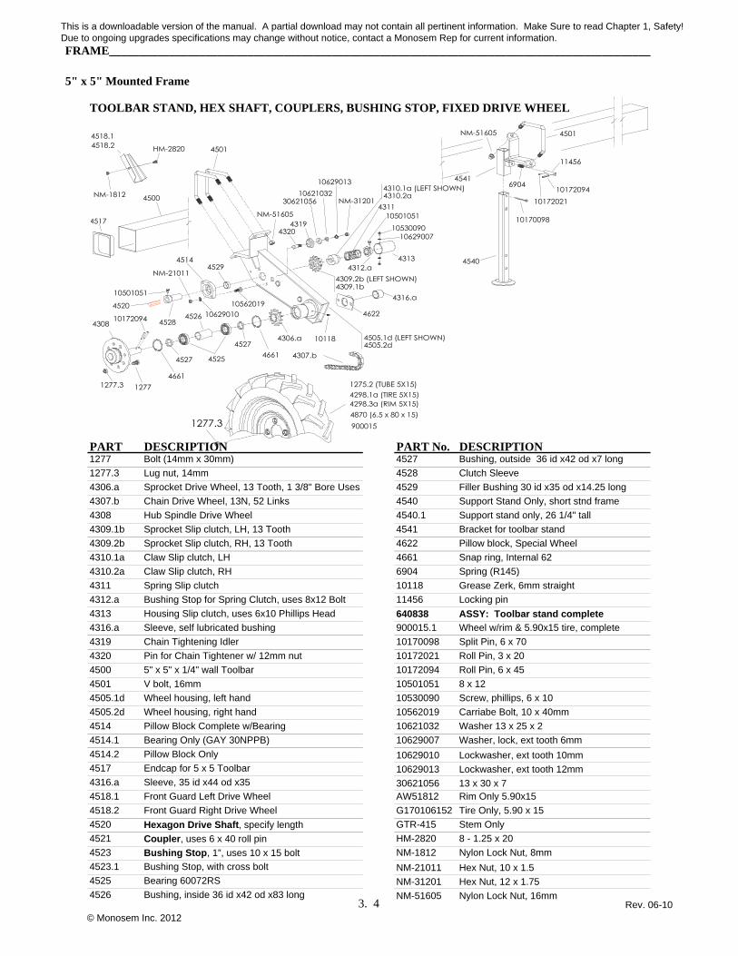
5" x 5" Mounted Frame
TOOLBAR STAND, HEX SHAFT, COUPLERS, BUSHING STOP, FIXED DRIVE WHEEL
PART DESCRIPTION PART No. DESCRIPTION1277 Bolt (14mm x 30mm) 4527 Bushing, outside 36 id x42 od x7 long
1277.3 Lug nut, 14mm 4528 Clutch Sleeve
4306.a Sprocket Drive Wheel, 13 Tooth, 1 3/8" Bore Uses 4529 Filler Bushing 30 id x35 od x14.25 long
4307.b Chain Drive Wheel, 13N, 52 Links 4540 Support Stand Only, short stnd frame
4308 Hub Spindle Drive Wheel 4540.1 Support stand only, 26 1/4" tall
4309.1b Sprocket Slip clutch, LH, 13 Tooth 4541 Bracket for toolbar stand
4309.2b Sprocket Slip clutch, RH, 13 Tooth 4622 Pillow block, Special Wheel
4310.1a Claw Slip clutch, LH 4661 Snap ring, Internal 62
4310.2a Claw Slip clutch, RH 6904 Spring (R145)
4311 Spring Slip clutch 10118 Grease Zerk, 6mm straight
4312.a Bushing Stop for Spring Clutch, uses 8x12 Bolt 11456 Locking pin
4313 Housing Slip clutch, uses 6x10 Phillips Head 640838 ASSY: Toolbar stand complete
4316.a Sleeve, self lubricated bushing 900015.1 Wheel w/rim & 5.90x15 tire, complete
4319 Chain Tightening Idler 10170098 Split Pin, 6 x 70
4320 Pin for Chain Tightener w/ 12mm nut 10172021 Roll Pin, 3 x 20
4500 5" x 5" x 1/4" wall Toolbar 10172094 Roll Pin, 6 x 45
4501 V bolt, 16mm 10501051 8 x 12
4505.1d Wheel housing, left hand 10530090 Screw, phillips, 6 x 10
4505.2d Wheel housing, right hand 10562019 Carriabe Bolt, 10 x 40mm
4514 Pillow Block Complete w/Bearing 10621032 Washer 13 x 25 x 2
4514.1 Bearing Only (GAY 30NPPB) 10629007 Washer, lock, ext tooth 6mm
4514.2 Pillow Block Only 10629010 Lockwasher, ext tooth 10mm4517 Endcap for 5 x 5 Toolbar 10629013 Lockwasher, ext tooth 12mm4316.a Sleeve, 35 id x44 od x35 30621056 13 x 30 x 74518.1 Front Guard Left Drive Wheel AW51812 Rim Only 5.90x15
4518.2 Front Guard Right Drive Wheel G170106152 Tire Only, 5.90 x 15
4520 Hexagon Drive Shaft, specify length GTR-415 Stem Only
4521 Coupler, uses 6 x 40 roll pin HM-2820 8 - 1.25 x 20
4523 Bushing Stop, 1”, uses 10 x 15 bolt NM-1812 Nylon Lock Nut, 8mm
4523.1 Bushing Stop, with cross bolt NM-21011 Hex Nut, 10 x 1.54525 Bearing 60072RS NM-31201 Hex Nut, 12 x 1.754526 Bushing, inside 36 id x42 od x83 long NM-51605 Nylon Lock Nut, 16mm
3. 4 Rev. 06-10
This is a downloadable version of the manual. A partial download may not contain all pertinent information. Make Sure to read Chapter 1, Safety! Due to ongoing upgrades specifications may change without notice, contact a Monosem Rep for current information.
© Monosem Inc. 2012

FRAME__________________________________________________________________________________________
5" x 5" Mounted Frame
ADJUSTABLE DRIVE WHEEL
PART No. DESCRIPTION PART No. DESCRIPTION1277 Lug nut and bolt (14mm x 30mm) 7083 Threaded handwheel
1277.3 Lug nut 14mm 9658 Bushing (7mm ID x 25mm long)
1534.A Counter clamp (120mm wide) 10118.A Grease zerk, 6mm, 45 degree
1538 Spacer bushing, 12x18x10mm long 11476 Lynch pin, 9mm dia.
4309.1B Sprocket slipclutch, LH, 13 teeth, mates with 4310.1a 11483 Pin, 19mm dia.
4309.2B Sprocket slipclutch, RH,13 teeth, shown above 900015.1 Tire & rim assembly (5.90x15)
4310.1A Claw slipclutch, lefthand (C12A on casting) AW51812 Rim only
4310.2A Claw slipclutch, righthand (C12B on casting) shown G170106152 Tire only (5.90x15)
4311 Spring for slipclutch HM-2816 Bolt, 8x16
4312.A Bushing & spring stop (uses 8x12 bolt) HM-2820 Bolt, 8x20
4313 Housing for slipclutch (fastens with 10530090) HM-61225 Bolt, 12x25
4317.3 Hex bushing (33mm wide) HM-61250 Bolt, 12x50
4319 Chain tightening idler HM-81670 Bolt, 16x70
4320 Pin for chain tightening idler, w/12mm nut NM-1801 8mm nut
4467.D Clutch assembly complete RH (w/4309.2b & 4310.2a) NM-31201 12mm nylon locknut
4467.G Clutch assembly complete LH (w/4309.1b & 4310.1a) NM-51605 16mm nylon locknut
4653 Hub, drive wheel NM-72005 20mm nylon locknut
4654 Spindle, hex shaped 10172067 Roll pin, 5x40
4655 See #4655.1 & #4655.2 10172091 Roll pin, 6x30
4655.1 Bearing only (S207FF ref. #) 10172092 Roll pin, 6x35
4655.2 Pillow block only (01LCTE 07 marking on cast housing) 10173020 Roll pin, 8x40
4656.A Rear sprocket, 13T, hex bore, takes a 8x40 roll pin 10200191 Plastic Washer, Black
4657.A Chain, 13N (66 links w/conn. link) 10530090 Screw, 6x10 phillips head
4658.A Drive chain shield 10561053 Carriage head bolt, 8x18
4659 Bearing (205KRR2 ref. #) 10620063 Washer, 8.5X16X1.5
4660 Snapring, internal (52mm) 10620064 Washer, 8.5x16x2
4710.1B Support frame, w/clutch to the right (since 1994) 10621055 Washer, 13x30x5
4710.2B Support frame, w/clutch to the left (since 1994) 10621056 Washer, 13x30x6
4711 Spacer bushing 10621061 Washer, 13x40x4
4714 Threaded rod, standard adjustment 10623003 Washer, 20.5x40x2
4715 Threaded pivot pin 10629007 External tooth locking washer, 6mm
4716 Spacer for spindle (hex bore, 8mm wide) 10629013 External tooth locking washer, 12mm
4717 Pivot pin (takes 12x25 bolt) 66005778 Trunnion Asm.
4726 Threaded rod, spring loaded adjustment 66005779 Trunnion Pin
4727 Housing for spring & shaft 650610
4728 Hex nut, 20mm, w/6mm hole
5666.2 Spring 653611 Complete ASSY: Screw adjust
Complete ASSY:Screw adjust, spring loaded
3. 5 Rev. 06-10
This is a downloadable version of the manual. A partial download may not contain all pertinent information. Make Sure to read Chapter 1, Safety! Due to ongoing upgrades specifications may change without notice, contact a Monosem Rep for current information.
© Monosem Inc. 2012

FRAME__________________________________________________________________________________________
5" x 5" Mounted FramePART No. DESCRIPTION
SINGLE TOOLBAR HITCH 1534.A Counter Clamp 120mm w/4 holes
4365.a Hitch Bar, Semi-Automtc Hitch (A12)
4366.c Locking Rod for Hitch Bar
4369 Sleeve Locking Rod
4370 Locking Spring
4480.2 Upper Hitch Pin, 1" DIA. X 3-3/4"
4480.3 Upper Hitch Pin, 1" DIA. X 5-3/8"4502 U Bolt, 16mm4517 5x5 Toolbar Endcap4530.2 Heavy-duty Mast
4531.1 Lower 3 Pt. Bracket, Left
4531.2 Lower 3 Pt. Bracket, Right
4532 Turbofan support Straps, 3 Pt. Hitch
4535.1 Hitch Pin, Cat. 1
4535.2 Hitch Pin, Cat. 2
4535.3 Hitch Pin, CAT II
4536 Bushing for Cat. 3
4549 Plastic Cap
DOUBLE TOOLBAR HITCH 4585 Reinforced Hitch Plate
4586 Bolt, 20x180mm
4587 Bushing, 20 id x30 od x60mm long
4603.a Upper Bar Advanced Hitch, 2.20m
4603.1a Upper Bar Advanced Hitch, 2.60m
4604.1 Support Bracket Turbofan Left
4604.2 Support Bracket Turbofan Right
4606.1 Toolbar Spacer, upper
4606.2 Toolbar Spacer, lower
4610.1B Hitch/ Spacer bracket
4611 Upper 3-Point Hitch Bracket
4612 Counter Clamp 140 mm w/ 4 holes
6968.1 T-bolt, 16mm
4612.2 Counter Clamp 140mm w/ 6 holes
11476 Lynch Pin
11476.1 Lynch Pin w/ Chain
10159069 Endcap Metal clip
10200182 Endcap, Plastic only10621046 Washer, 13x27x2
10622069 Washer, 17.5 x 30 x 4mm
ADVANCED HITCH H-6451 Bolt, 7/8" x 4-1/2"
HM-41025 Bolt, 10 x 25mm
HM-71445 Bolt, 14 x 45mm
HM-81640 Bolt, 16 x 40mm
HM-81670 Bolt, 16 x 70mm
HM-81680 Bolt, 16 x 80mm
N-6101 Nylock, 3/4-10"
NM-21015 Nylock, 10mm
NM-31205 Nylock, 12mm
NM-41205 Nylock, 14mmNM-51605 Nylock, 16mm
NM-72005 Nylock, 20mm
3. 6 Rev. 06-10
This is a downloadable version of the manual. A partial download may not contain all pertinent information. Make Sure to read Chapter 1, Safety! Due to ongoing upgrades specifications may change without notice, contact a Monosem Rep for current information.
© Monosem Inc. 2012