2013 daytona race kit manual h series issue 1
TRANSCRIPT

Page 1 Publication part number A9900675 issue 1, ADC12359 © Triumph Designs Ltd. 2013
2013 Daytona 675 and Daytona 675 R
(From VIN 564948)
Motorcycle Race Kit Manual
FOR CLOSED-CIRCUIT USE ONLY
Table of Contents
Page 2
General Information . . . . . . . . . . . . . . . . . . . . . . . . . . . . . . . . . . . . . . . . . . . . . . . . . . . . . . .3
Engine Parts . . . . . . . . . . . . . . . . . . . . . . . . . . . . . . . . . . . . . . . . . . . . . . . . . . . . . . . . . . . . . .5
Cylinder Head and Cylinder Base Gaskets . . . . . . . . . . . . . . . . . . . . . . . . . . . . . . . . . . . . . . . . . . . . . . . . . . . . . . .5
Camshaft and Valve Spring Kits . . . . . . . . . . . . . . . . . . . . . . . . . . . . . . . . . . . . . . . . . . . . . . . . . . . . . . . . . . . . . . .7
Manually Adjustable Camshaft Drive Chain Tensioner . . . . . . . . . . . . . . . . . . . . . . . . . . . . . . . . . . . . . . . . . . . . .9
Exhaust Valve Kit . . . . . . . . . . . . . . . . . . . . . . . . . . . . . . . . . . . . . . . . . . . . . . . . . . . . . . . . . . . . . . . . . . . . . . . . . .11
Secondary Air Injection (SAI) Blanking Kit . . . . . . . . . . . . . . . . . . . . . . . . . . . . . . . . . . . . . . . . . . . . . . . . . . . . . .12
Exhaust System, Race (Arrow) . . . . . . . . . . . . . . . . . . . . . . . . . . . . . . . . . . . . . . . . . . . . . . . . . . . . . . . . . . . . . . .14
Air Filter Kit . . . . . . . . . . . . . . . . . . . . . . . . . . . . . . . . . . . . . . . . . . . . . . . . . . . . . . . . . . . . . . . . . . . . . . . . . . . . . .18
Manual Idle Speed Adjuster Kit . . . . . . . . . . . . . . . . . . . . . . . . . . . . . . . . . . . . . . . . . . . . . . . . . . . . . . . . . . . . . .19
Cover Protectors Kit (Superstock) . . . . . . . . . . . . . . . . . . . . . . . . . . . . . . . . . . . . . . . . . . . . . . . . . . . . . . . . . . . . .20
Cover Protectors Kit (Supersport) . . . . . . . . . . . . . . . . . . . . . . . . . . . . . . . . . . . . . . . . . . . . . . . . . . . . . . . . . . . . .21
Electrical Parts . . . . . . . . . . . . . . . . . . . . . . . . . . . . . . . . . . . . . . . . . . . . . . . . . . . . . . . . . . .22
Race Alternator Kit . . . . . . . . . . . . . . . . . . . . . . . . . . . . . . . . . . . . . . . . . . . . . . . . . . . . . . . . . . . . . . . . . . . . . . . . .22
Race Engine Control Module (ECM) . . . . . . . . . . . . . . . . . . . . . . . . . . . . . . . . . . . . . . . . . . . . . . . . . . . . . . . . . .24
Race Harness Kit . . . . . . . . . . . . . . . . . . . . . . . . . . . . . . . . . . . . . . . . . . . . . . . . . . . . . . . . . . . . . . . . . . . . . . . . . .26
Chassis Parts . . . . . . . . . . . . . . . . . . . . . . . . . . . . . . . . . . . . . . . . . . . . . . . . . . . . . . . . . . . .29
Quickshifter, Race . . . . . . . . . . . . . . . . . . . . . . . . . . . . . . . . . . . . . . . . . . . . . . . . . . . . . . . . . . . . . . . . . . . . . . . . .29
Race Wheel Kit . . . . . . . . . . . . . . . . . . . . . . . . . . . . . . . . . . . . . . . . . . . . . . . . . . . . . . . . . . . . . . . . . . . . . . . . . . .30
Race Frame Protector Kit . . . . . . . . . . . . . . . . . . . . . . . . . . . . . . . . . . . . . . . . . . . . . . . . . . . . . . . . . . . . . . . . . . . .31
Page 3
General Information
Please note:
• The Race Kit parts detailed in this publication are made in accordance with FIM technical regulations and areNOT road legal.
• The Race Kit parts covered in this publication are intended for racing purposes only and any Triumphmotorcycle fitted with such kits MUST NOT be used on public roads.
• The Race Kit parts detailed in this publication may only be used on a closed-circuit in the hands of experiencedriders.
• Before fitting any Race Kit parts, customers should check the technical regulations of their race class to ensureconformity.
• The information provided in this publication should always be used together with the official Triumph Daytona675 service manual.
• Completely read all the instructions before commencing the installation and set up of the Race Kit in order tobecome thoroughly familiar with the kit’s features and the installation process.
• When removing components which incorporate a gasket ALWAYS ensure a new gasket is fitted on re-assembly.
• The Race Kit parts detailed in this publication are not covered by any warranty.
• Specifications are subject to change without notice.
• The information contained in this publication is accurate at the time of final approval, however, TriumphMotorcycles LTD reserves the right to amend the information at any time without notice.
• Whilst every effort is made to include the latest information in the service manual, this is not always possible.The latest information and technical changes are provided to authorised Triumph dealers via Technical News. Itis recommended you contact an authorised Triumph dealer to request this information.
Warnings, Cautions and Notes
Throughout this publication particularly important information is presented in the following form:
Note:
• This note symbol indicates points of particular interest for more efficient and convenient operation.
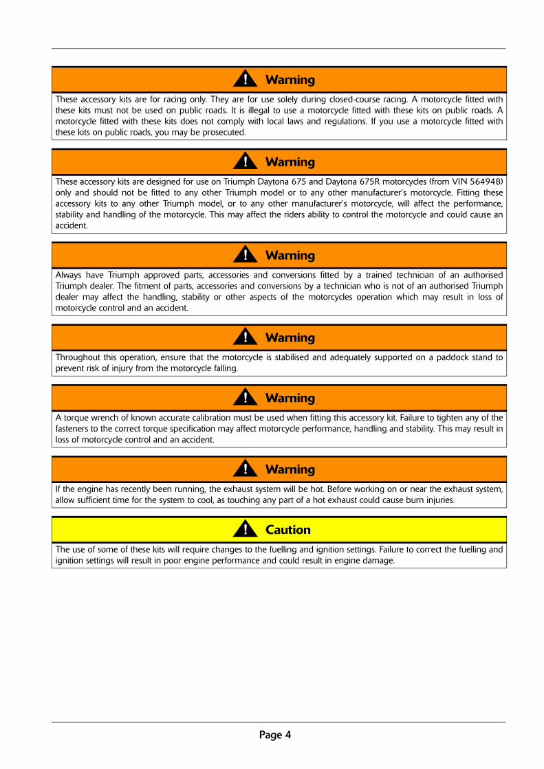
WarningThis warning symbol identifies special instructions or procedures, which if not correctly followed could result in personalinjury, or loss of life.
CautionThis caution symbol identifies special instructions or procedures, which if not strictly observed, could result in damage to,or destruction of, equipment.
Page 4
WarningThese accessory kits are for racing only. They are for use solely during closed-course racing. A motorcycle fitted withthese kits must not be used on public roads. It is illegal to use a motorcycle fitted with these kits on public roads. Amotorcycle fitted with these kits does not comply with local laws and regulations. If you use a motorcycle fitted withthese kits on public roads, you may be prosecuted.
WarningThese accessory kits are designed for use on Triumph Daytona 675 and Daytona 675R motorcycles (from VIN 564948)only and should not be fitted to any other Triumph model or to any other manufacturer’s motorcycle. Fitting theseaccessory kits to any other Triumph model, or to any other manufacturer’s motorcycle, will affect the performance,stability and handling of the motorcycle. This may affect the riders ability to control the motorcycle and could cause anaccident.
WarningAlways have Triumph approved parts, accessories and conversions fitted by a trained technician of an authorisedTriumph dealer. The fitment of parts, accessories and conversions by a technician who is not of an authorised Triumphdealer may affect the handling, stability or other aspects of the motorcycles operation which may result in loss ofmotorcycle control and an accident.
WarningThroughout this operation, ensure that the motorcycle is stabilised and adequately supported on a paddock stand toprevent risk of injury from the motorcycle falling.
WarningA torque wrench of known accurate calibration must be used when fitting this accessory kit. Failure to tighten any of thefasteners to the correct torque specification may affect motorcycle performance, handling and stability. This may result inloss of motorcycle control and an accident.
WarningIf the engine has recently been running, the exhaust system will be hot. Before working on or near the exhaust system,allow sufficient time for the system to cool, as touching any part of a hot exhaust could cause burn injuries.
CautionThe use of some of these kits will require changes to the fuelling and ignition settings. Failure to correct the fuelling andignition settings will result in poor engine performance and could result in engine damage.
Page 5
Engine Parts
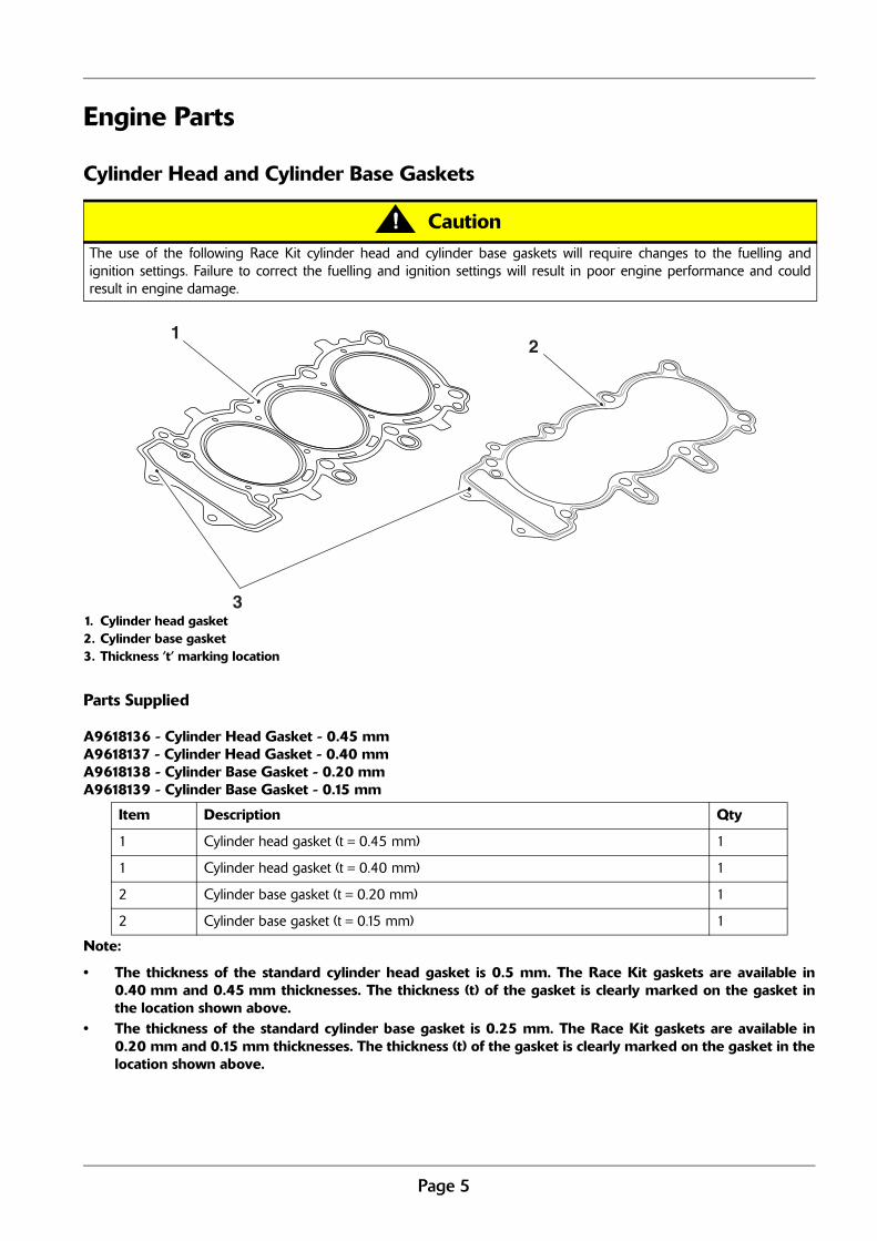
Cylinder Head and Cylinder Base Gaskets
1. Cylinder head gasket2. Cylinder base gasket3. Thickness ’t’ marking location
Parts Supplied
A9618136 - Cylinder Head Gasket - 0.45 mmA9618137 - Cylinder Head Gasket - 0.40 mmA9618138 - Cylinder Base Gasket - 0.20 mm A9618139 - Cylinder Base Gasket - 0.15 mm
Note:
• The thickness of the standard cylinder head gasket is 0.5 mm. The Race Kit gaskets are available in0.40 mm and 0.45 mm thicknesses. The thickness (t) of the gasket is clearly marked on the gasket inthe location shown above.
• The thickness of the standard cylinder base gasket is 0.25 mm. The Race Kit gaskets are available in0.20 mm and 0.15 mm thicknesses. The thickness (t) of the gasket is clearly marked on the gasket in thelocation shown above.
CautionThe use of the following Race Kit cylinder head and cylinder base gaskets will require changes to the fuelling andignition settings. Failure to correct the fuelling and ignition settings will result in poor engine performance and couldresult in engine damage.
Item Description Qty
1 Cylinder head gasket (t = 0.45 mm) 1
1 Cylinder head gasket (t = 0.40 mm) 1
2 Cylinder base gasket (t = 0.20 mm) 1
2 Cylinder base gasket (t = 0.15 mm) 1
21
3
Page 6
Note:
• Due to variation in production tolerances, theRace Kit cylinder head and cylinder basegaskets may not be suitable for all engines. Usethe appropriate gaskets to adjust the squishheight (the squish height is the gap betweenthe flat portion of the piston and the cylinderhead).
• In some cases, it may be necessary to use thestandard gaskets to achieve the correct squishclearance. Always ensure that the chosengaskets provide a minimum squish clearance of0.75 mm.
1. Remove the cylinder head in line with theprocedures detailed in the Daytona 675 servicemanual.
2. Position a piece of solder (with a diameter ofapproximately 1.3 mm) on the four squish surfacesof each piston and hold in place with a small amountof grease. Ensure the solder is positioned in line withthe corresponding squish surfaces on the cylinderhead.
3. Refit the cylinder head with the original cylinderhead and base gaskets.
4. Slowly turn the engine over, by hand, to compressthe solder to the same height as the squishclearance.
5. Remove the cylinder head and measure thecompressed thickness of the solder. Therecommended minimum squish clearance is0.75 mm.
6. Select the appropriate gasket thicknesses to achievethe correct squish clearance. For example:
• If the minimum squish clearance is measured at0.90 mm with the standard 0.50 mm headgasket and 0.25 mm base gasket fitted.
• Fit the 0.40 mm head gasket and the 0.20 mmbase gasket to achieve a squish clearance of0.75 mm.
Note:
• In some cases, it may be necessary to use thestandard gaskets to achieve the correct squishclearance.
7. Fit the chosen cylinder head and base gasketsfollowing the procedures detailed in the Daytona675 service manual.
WarningRunning the engine at less than the minimumrecommended squish height can lead to the pistonscontacting the cylinder head and valves, causing majorengine damage. This could cause loss of motorcyclecontrol and an accident.
Page 7
Camshaft and Valve Spring Kits
Parts Supplied
Camshaft, Inlet - A9618160
Camshaft, Exhaust - A9618161
Valve Spring Kit - A9618086
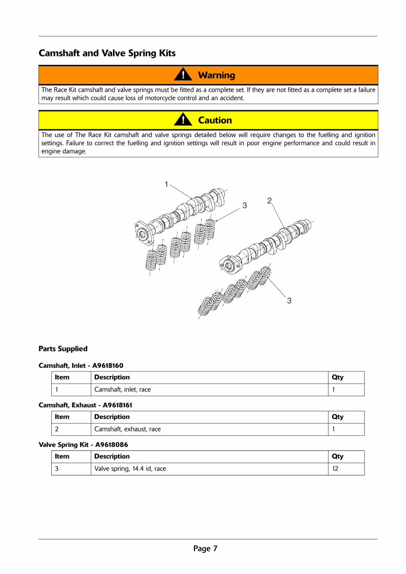
WarningThe Race Kit camshaft and valve springs must be fitted as a complete set. If they are not fitted as a complete set a failuremay result which could cause loss of motorcycle control and an accident.
CautionThe use of The Race Kit camshaft and valve springs detailed below will require changes to the fuelling and ignitionsettings. Failure to correct the fuelling and ignition settings will result in poor engine performance and could result inengine damage.
Item Description Qty
1 Camshaft, inlet, race 1
Item Description Qty
2 Camshaft, exhaust, race 1
Item Description Qty
3 Valve spring, 14.4 id, race 12
1
23
3
Page 8
Note:
• The standard inlet cam is 9.40 mm max lift and 258.98° duration. The Race Kit inlet cam is 9.40 mmmax lift and 265° duration.
• The standard exhaust cam is 8.70 mm max lift and 247.08° duration. The Race Kit exhaust cam is8.70 mm max lift and 260° duration.
• The Race Kit valve spring must be used in conjunction with the standard spring platforms and retainers.The fitted length of the race springs is the same as the standard spring.
1. The Race Kit valve springs should be assembled inthe same manner as the standard valve springs.Follow the procedure detailed in section 3 of theDaytona 675 service manual. Ensure the springs areinstalled with the close wound, colour coded end ofthe springs facing downwards, towards the piston.
2. The Race Kit camshafts should be assembled in thesame manner as the standard camshafts. Follow theprocedure detailed in section 3 of the Daytona 675service manual.
3. Assemble the original camshaft sprockets to the RaceKit camshafts following the procedure detailed insection 3 of the Daytona 675 service manual.
4. The camshafts should be timed using camdegreeing equipment which typically consists of adegree wheel, pointer, dial indicator and piston stop.Optimum cam timing will depend on the exactspecification of the engine, but a recommendedstarting point is as follows:
• Inlet Maximum Opening Point (IMOP) 108°After Top Dead Centre (ATDC).
• Exhaust Maximum Opening Point (EMOP)108º Before Top Dead Centre (BTDC).
5. Always check the inlet and exhaust piston to valveclearance for the timing selected to use, beforerunning the engine. You must ensure bothclearances are adequate. As a guide, the standardnominal piston to valve clearance is 1.0 mm inlet &1.4 mm exhaust.
6. When the desired timing has been set, the sprocketretaining fixings should be tightened to 22 Nm.
Note:
• If the sprocket retaining fixings are released forany reason they must be discarded andreplaced with new fixings. Apply ThreeBond1305 to the threads before tightening.

Page 9
Manually Adjustable Camshaft Drive Chain Tensioner
Parts Supplied - A9618108
1. Remove the standard tensioner following theprocedure detailed in the Daytona 675 servicemanual. Discard the gasket and retain the fixings forre-use.
2. Remove the camshafts following the proceduredetailed in the Daytona 675 service manual.
3. Remove the pin locating the tensioner blade to thecrankcase, retain the pin for re-use. Remove thetensioner blade from the top of the camshaft drivechain chest.
4. Lower the new tensioner blade provided into thecamshaft drive chain chest, from the top. Locate inposition with the original pin.
5. Refit the camshafts following the procedure detailedin the Daytona 675 service manual.
6. Thoroughly clean the tensioner mounting surface onthe cylinder head.
1
2
Item Description Qty
1 Manual camshaft drive chain tensioner assembly 1
2 Camshaft drive chain tensioner blade 1
CautionDo not start the motorcycle engine with the tensionerremoved. If the motorcycle engine is started with thetensioner removed it could result in engine damage.

Page 10
7. Back off the plunger locknut on the new tensionerassembly before installation.
1. Plunger locknut
8. Lightly coat the two large O-rings with oil, and fit anew gasket.
9. Install the new tensioner assembly and secure withthe original fixings.
10. Tighten the tensioner fixings to a torque value of9 Nm.
11. Finger tighten the plunger on the new tensionerwhile turning the crankshaft by hand. At certainpoints during engine rotation you will feel theplunger tighten as it takes up the slack in thecamshaft drive chain. DO NOT force the plunger,continue steady finger tightening only to take up theslack in the chain as you rotate the crankshaft.
1. Plunger2. Plunger locknut
12. When the slack in the camshaft drive chain has beencompletely taken up, back off the plunger by 1/4turn.
13. While holding the plunger in position, tighten theplunger locknut to a torque value of 9 Nm. Ensurethe plunger is not allowed to turn while tighteningthe locknut.
14. Re-check the chain tension.
15. Fit a new gasket to the right hand crank cover.
16. Refit the crank cover, tightening the fixings to10 Nm.
1. Crank cover2. Fixings
17. Following the procedure detailed in the Daytona 675service manual, check the valve clearances andadjust as necessary.
18. Refit the camshaft cover, as described in the Daytona675 service manual.
1
12
chwx
2
2
2
2
1
Page 11
Exhaust Valve Kit
Parts Supplied - A9618162
Note:
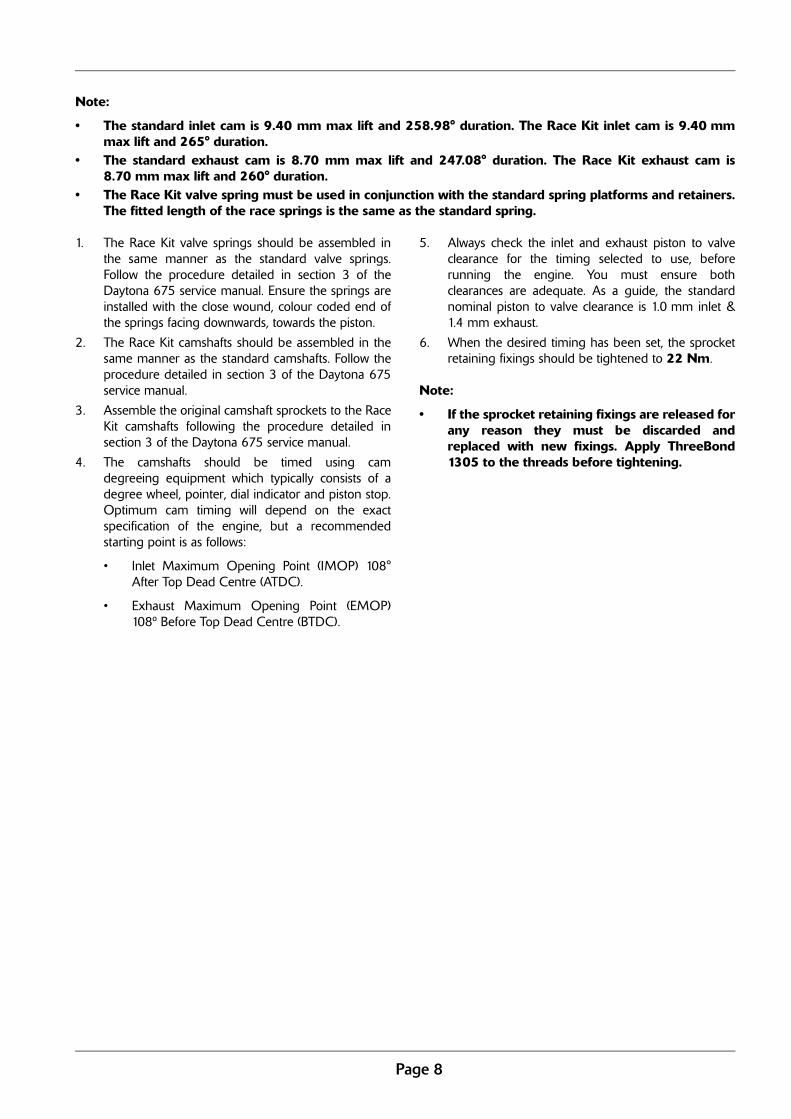
• The valves supplied in the Race Kit are used to increase compression ratio, by having a flat face on thecombustion chamber side.
1. Remove the existing inlet and exhaust valvesfollowing the procedure detailed in section 3 of theDaytona 675 service manual.
2. Assemble the original inlet valves and Race exhaustvalves, following the procedure detailed in section 3of the Daytona 675 service manual.
CautionThe use of the following Race Kit exhaust valves will require changes to the fuelling and ignition settings. Failure tocorrect the fuelling and ignition settings will result in poor engine performance and could result in engine damage.
1
Item Description Qty
1 Exhaust valve, 24.2 dia 6

Page 12
Secondary Air Injection (SAI) Blanking Kit
Parts Supplied - A9618094
Note:
• This kit includes the necessary components to blank-off the secondary air injection channels in thecylinder head when the system is removed from the motorcycle.
• Refer to the appropriate sections in the Daytona 675 service manual to carry out the proceduresoutlined in steps 1 to 11 overleaf.
Item Description Qty
1 Reed valve cover, single 1
2 Reed valve cover, double 1
3 Dowel, solid 3
4 Sealing cap, air box 1
5 Bolt, M6 x 16 mm 4
6 Washer 2
7 Flanged sleeve 2
1
4
2
537
6
Page 13
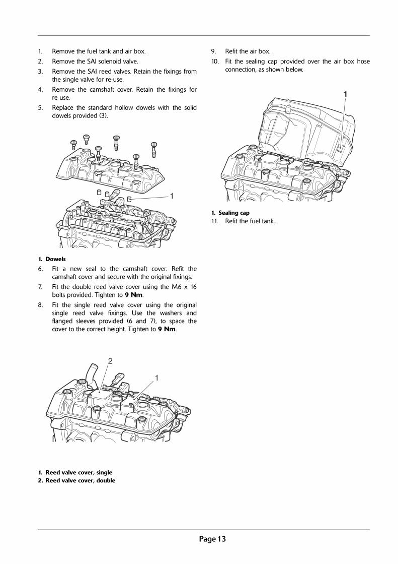
1. Remove the fuel tank and air box.
2. Remove the SAI solenoid valve.
3. Remove the SAI reed valves. Retain the fixings fromthe single valve for re-use.
4. Remove the camshaft cover. Retain the fixings forre-use.
5. Replace the standard hollow dowels with the soliddowels provided (3).
1. Dowels
6. Fit a new seal to the camshaft cover. Refit thecamshaft cover and secure with the original fixings.
7. Fit the double reed valve cover using the M6 x 16bolts provided. Tighten to 9 Nm.
8. Fit the single reed valve cover using the originalsingle reed valve fixings. Use the washers andflanged sleeves provided (6 and 7), to space thecover to the correct height. Tighten to 9 Nm.
1. Reed valve cover, single2. Reed valve cover, double
9. Refit the air box.
10. Fit the sealing cap provided over the air box hoseconnection, as shown below.
1. Sealing cap11. Refit the fuel tank.
1
1
2
1
Page 14
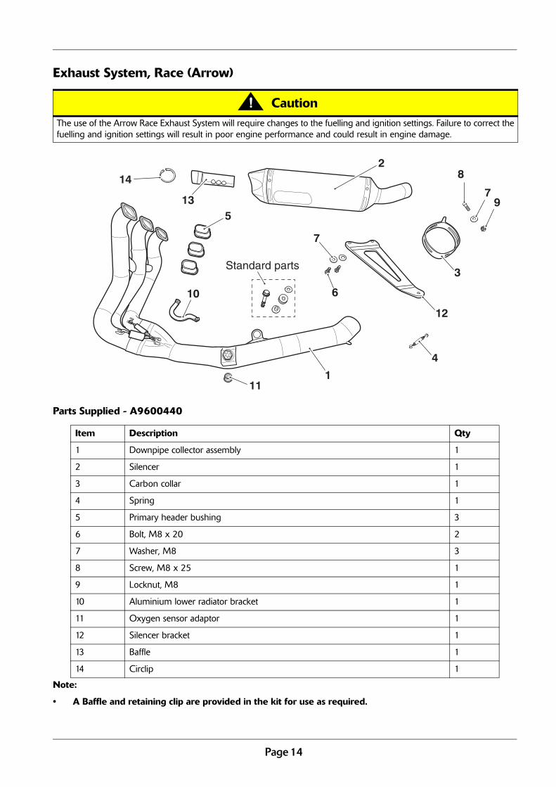
Exhaust System, Race (Arrow)
Parts Supplied - A9600440
Note:
• A Baffle and retaining clip are provided in the kit for use as required.
CautionThe use of the Arrow Race Exhaust System will require changes to the fuelling and ignition settings. Failure to correct thefuelling and ignition settings will result in poor engine performance and could result in engine damage.
Item Description Qty
1 Downpipe collector assembly 1
2 Silencer 1
3 Carbon collar 1
4 Spring 1
5 Primary header bushing 3
6 Bolt, M8 x 20 2
7 Washer, M8 3
8 Screw, M8 x 25 1
9 Locknut, M8 1
10 Aluminium lower radiator bracket 1
11 Oxygen sensor adaptor 1
12 Silencer bracket 1
13 Baffle 1
14 Circlip 1
1
2
3
4
5
8
7
6
12
10
7
11
Standard parts
913
14

Page 15
1. Remove the seat and battery following theprocedures detailed in the Daytona 675 servicemanual.
2. Remove the lower fairings, cockpit infill panels,radiator infill panels, radiator, pillion foot resthangers, right hand control plate, transmissionlinkage, sprocket cover, left hand frame finisher,purge valve, exhaust system and the exhaustbutterfly valve actuator and actuator cables followingthe procedures detailed in the Daytona 675 servicemanual.
3. Retain the exhaust header nuts for re-use. Replace ifrequired.
4. Remove and discard the exhaust header seals.Renew exhaust header seals if required.
1. Seals
5. Retain the washer, grommet and flanged sleevefrom the left hand side mount and the M8 x 50fixing from the left hand side mount for re-use.
6. Remove the lower radiator mounting bracket, retainthe fixing and compression limiter for re-use.
Note:
• To obtain maximum performance the exhaustport should be machined, removing materialfrom the area shown in red. The exhaust portshape should match the inside surface of theprimary header bush.
7. Fit new exhaust header seals (if required) ensuringthat the face of the seal with the tab is facing thecylinder head.
1. Seals2. Seal tab
8. Thoroughly clean the mating surfaces of the primaryheader bushings (5) and downpipe collectorassembly (1).
9. Apply silicone sealant to the mating surface of thethree primary header bushings. The recommendedsealant is Dow Corning Firestop 700 white silicone.
10. Insert the primary header bushings into thedownpipe collector assembly.
1. Header bushings2. Downpipe collector assembly3. Mating surfaces
Note:
• The primary header bushings should beorientated such that none of the exhaust portopening is obscured.
11. Position the downpipe collector assembly to thecylinder head and align the header pipe flanges tothe fixing points. Fit the exhaust header nutsretained from disassembly, do not fully tighten at thisstage.
1
2
1
1
2
3

Page 16
12. Loosely secure the downpipe collector assemblylower mounting point to the frame using the originalfixings retained from the left and right hand sidemounts.
1. Fixing
13. Secure the silencer bracket (12) to the right handrear footrest hanger mounting points using the twoM8 x 20 Bolts (6) and washers (7) provided. Tightento 22 Nm.
1. Silencer bracket
14. Place the carbon collar (3) onto the silencer (2).
15. Push the silencer onto the downpipe collectorassembly and secure using the spring provided (4).
16. Align the carbon collar with the outside of thesilencer bracket and secure using the M8 x 25 screw(8), M8 washer (7) and M8 locknut (9) provided.Tighten to 9 Nm.
1. Downpipe collector assembly2. Silencer3. Spring4. Carbon collar5. Silencer bracket6. Capscrew, washer and nut
1
1
1
25
6
4
3
Page 17
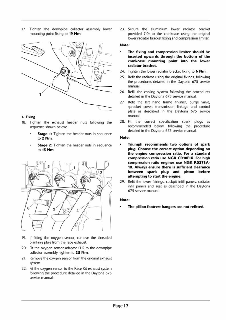
17. Tighten the downpipe collector assembly lowermounting point fixing to 19 Nm.
1. Fixing
18. Tighten the exhaust header nuts following thesequence shown below:
• Stage 1: Tighten the header nuts in sequenceto 2 Nm.
• Stage 2: Tighten the header nuts in sequenceto 15 Nm.
19. If fitting the oxygen sensor, remove the threadedblanking plug from the race exhaust.
20. Fit the oxygen sensor adaptor (11) to the downpipecollector assembly. tighten to 25 Nm.
21. Remove the oxygen sensor from the original exhaustsystem.
22. Fit the oxygen sensor to the Race Kit exhaust systemfollowing the procedure detailed in the Daytona 675service manual.
23. Secure the aluminium lower radiator bracketprovided (10) to the crankcase using the originallower radiator bracket fixing and compression limiter.
Note:
• The fixing and compression limiter should beinserted upwards through the bottom of thecrankcase mounting point into the lowerradiator bracket.
24. Tighten the lower radiator bracket fixing to 6 Nm.
25. Refit the radiator using the original fixings, followingthe procedures detailed in the Daytona 675 servicemanual.
26. Refill the cooling system following the proceduresdetailed in the Daytona 675 service manual.
27. Refit the left hand frame finisher, purge valve,sprocket cover, transmission linkage and controlplate as described in the Daytona 675 servicemanual.
28. Fit the correct specification spark plugs asrecommended below, following the proceduredetailed in the Daytona 675 service manual.
Note:
• Triumph recommends two options of sparkplug. Choose the correct option depending onthe engine compression ratio. For a standardcompression ratio use NGK CR10EIX. For highcompression ratio engines use NGK R0373A-10. Always ensure there is sufficient clearancebetween spark plug and piston beforeattempting to start the engine.
29. Refit the lower fairings, cockpit infill panels, radiatorinfill panels and seat as described in the Daytona675 service manual.
Note:
• The pillion footrest hangers are not refitted.
1
cicg_1
5 13
6 2 4
Page 18
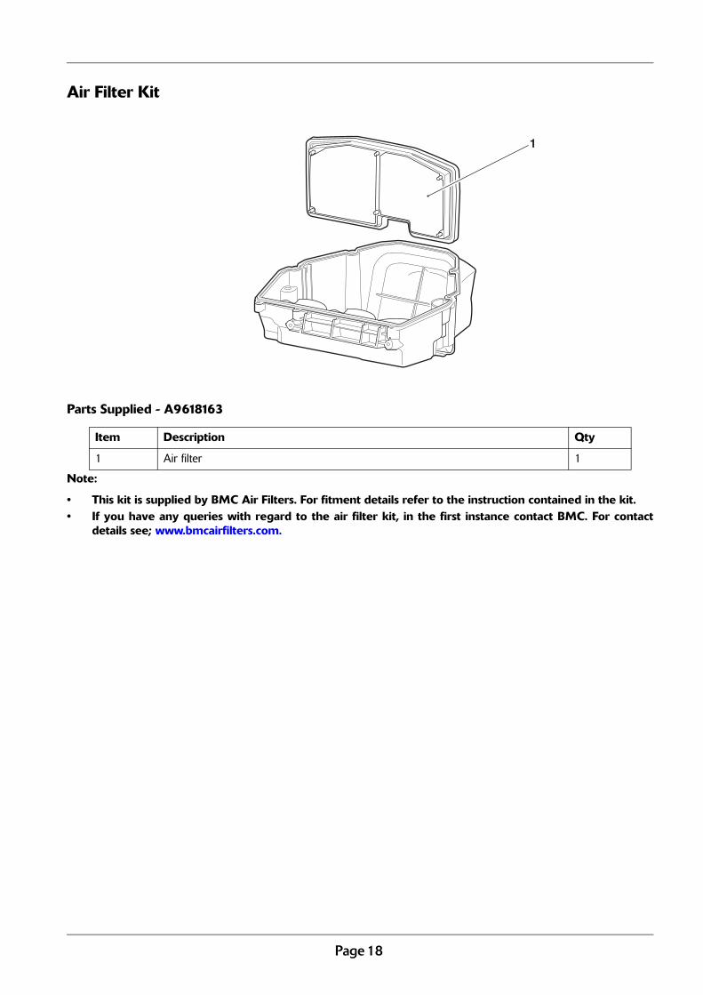
Air Filter Kit
Parts Supplied - A9618163
Note:
• This kit is supplied by BMC Air Filters. For fitment details refer to the instruction contained in the kit.• If you have any queries with regard to the air filter kit, in the first instance contact BMC. For contact
details see; www.bmcairfilters.com.
Item Description Qty
1 Air filter 1
1

Page 19
Manual Idle Speed Adjuster Kit
Parts Supplied - A9618076
1. Remove the throttle body assembly following theprocedure detailed in the Daytona 675 servicemanual.
2. Remove the throttle stop screw and nut from thethrottle body assembly.
3. Fit the manual adjuster screw and compressionspring supplied (items 1 & 2).
4. Refit the throttle body assembly following theprocedure detailed in the Daytona 675 servicemanual.
5. Adjust the idle speed using the manual adjusterscrew (item 1) as required.
1
2
Standard Parts
Item Description Qty
1 Screw, manual adjuster 1
2 Spring, compression coil 1

Page 20
Cover Protectors Kit (Superstock)
Parts Supplied - A9618132
Note:
• For fitment, refer to the comprehensive fitting instructions supplied with the Cover Protectors Kit.
Item Description Qty
1 Alternator cover protector 1
2 Clutch cover protector 1
3 Crank cover protector 1
4 Bolt, M6 x 1 x 30 8
5 Bolt, M6 x 1 x 20 1
1
2
3
4
5
cifa

Page 21
Cover Protectors Kit (Supersport)
Parts Supplied - A9618172
Note:
• For fitment, go to www.triumphinstructions.com and enter the kit number A9618132. Follow Steps 1 to6 of the comprehensive fitting instructions.
Item Description Qty
1 Clutch cover protector 1
2 Crank cover protector 1
3 Bolt, M6 x 1 x 30 5
4 Bolt, M6 x 1 x 20 1
1
2
3
4

Page 22
Electrical Parts
Race Alternator Kit
Parts Supplied - A9618154
Alternator Puller Tool - A3880206
Item Description Qty
1 Rotor, race AC Generator 1
2 Stator, race AC Generator (includes crank sensor) 1
3 Screw, caphead, M6 x 1 x 12, ENC (to retain sprag clutch housing) 6
4 Screw, skt hd cap, M5 x 0.8 x 20 4
5 Screw, skt hd cap, M5 x 0.8 x 10, ENC 7
6 Plate, wire retainer 1
7 Gasket, alternator cover (standard part) 1
8 Cover, alternator (unpainted sand casting) 1
9 Protector 1
10 Screw, cap/hd, M6 x 1 x 20 3
11 Bracket, cable guide, ACG stator 1
Item Description Qty
1 Puller tool, alternator 1
1
3
5
5
6
StandardPart
11
2
7 8
9
10
10
4
Standard Part120 Nm
StandardPart
Page 23
1. Remove the alternator as described in section 17 ofthe service manual.
2. Remove the starter drive gear and sprag clutch fromthe alternator rotor as described in section 7 of theservice manual. Discard the original fixings.
3. Using the M6 x 12 mm screws provided (3), fit thesprag clutch and starter drive gear to the race rotor(1) following the procedure detailed in section 7 ofthe service manual.
4. Remove all grease and oil from the taper surfaces onboth the crankshaft and rotor before assembly.
5. Assemble the race rotor and sprag clutch assemblyto the crankshaft following the procedure detailed insection 17 of the service manual.
6. Using the M5 x 20 mm screws provided (4),assemble the race stator (2) to the alternator coverprovided (8). Tighten to 12 Nm.
7. Apply silicone sealant to the cable grommet(ThreeBond 1215 is recommended), and align thecable to the exit slot.
8. Using two of the M5 x 10 mm screws provided (5),assemble the crankshaft sensor to the alternatorcover. Tighten to 6 Nm.
9. Fit the original wire retaining plate and the wireretaining plates supplied in the race kit (6 & 11) tothe alternator cover and secure with the remainingM5 x 10 mm screws provided (5). Tighten to 6 Nm.
10. Position the new gasket provided (7) to thecrankshaft dowels, then fit the race alternator coverand stator assembly to the crankcase following theprocedure detailed in the service manual.
11. Using the M6 x 20 screws provided (11), assemblethe alternator cover protector (10) to the alternatorcover. Tighten to 9 Nm.
Rotor Removal - Race AC Generator
1. Clean the alternator rotor removing all traces of oil.
2. Fit the service tool T3880375 to the outsidediameter of the rotor. Retain the tool to prevent thecrankshaft from rotating and remove the centre boltfrom the crankshaft.
3. With the crankshaft bolt removed, locate the spigotof the thrust pad supplied with service toolA3880206 into the end of the crankshaft.
4. Assemble the threaded portion of service toolA3880206 into the threaded portion of the rotor.Ensure the thrust pad does not fall out duringassembly of the service tool.
5. Hold the service tool T3880375 to prevent rotationof the rotor, then tighten service tool A3880206 torelease the taper seating of the rotor from thecrankshaft.
6. Withdraw the rotor and service tools as an assemblyand then separate the tools from the rotor. Collectthe woodruff key and the service tool thrust padfrom the crankshaft.
CautionDo not use tools of any kind to tighten the service toolT3880375. Tighten the tool by hand only. Over-tightening of the service tool will lead to damage of thealternator rotor.
Page 24
Race Engine Control Module (ECM)
Part supplied - A9828019
Note:
• The Race ECM will only work with the Race Harnesses A9828020 (non ABS) and A9828021 (ABS).• The Race ECM is pre-programmed for use with the following set of Race Kits: Inlet & Exhaust
Camshafts, Exhaust Valves, Air Filter Kit and Arrow Race Exhaust System. The tune has been developedto suit a compression ratio of 14:1 with enlarged and polished inlet ports and the exhaust ports modifiedas recommended on page 15.
• The rev limit on the race ECM has been increased from 14400 RPM to 15500 RPM.• The indicated speed shown on the instruments is calibrated for the standard gearbox. If the final drive
ratio is changed, the indicated speed will be incorrect.• Idle speed should be set to between 1,500 and 1,800 RPM.
ECM Malfunction Indicator Light:
• This will flash a sequence of error codes if any faults are present.• Flash codes have a long flash for the first digit and a short flash for the second digit. For example; fault
code “32” would be: long, long, long, short, short. • When a fault has been identified and rectified, the ECM can be cleared by the following sequence: full
throttle, ignition ON; flick the engine stop switch off/on/off/on/off.
CautionThe Race ECM MUST be used with the following Race Kits; A9618160 Camshaft - Inlet, A9618161 Camshaft - Exhaust,A9618162 Exhaust Valves, A9618086 Valve Spring Kit, A9600440 Arrow Race Exhaust System, A9618163 Air Filter Kitand A9828020 (non ABS) or A9828021 (ABS) Race Harness Kit. Failure to use the Race ECM with the Race kits listedabove will result in incorrect fuelling and ignition settings.
Item Description Qty
1 Race ECM 1

Page 25
Fault Code Table
CautionNo ECM faults should be present during motorcycle operation. If the motorcycle is used with ECM faults present it willbe operating in default ‘limp home’ mode only which will produce inconsistent operation.
Flash Code Problem
02 Crank position sensor
06 Throttle position sensor
09 Map sensor
12 Coolant temperature sensor
13 Intake air temperature sensor
14 Atmospheric air pressure sensor
15 Roll-over sensor
22 Gear position sensor
24 Ignition switch circuit
25 Battery voltage supply
26 5V sensor supply
27 5V sensor supply
33 Lower injector # 1
34 Lower injector # 2
35 Lower injector # 3
37 Ignition coil # 1
38 Ignition coil # 2
39 Ignition coil # 3
41 Fuel pump
43 Cooling fan relay
65 EEPROM error
66 Instrument communication error
68 MAP sensor pipe disconnected
70 Vehicle speed sensor
76 Instrument communication error
96 Upper injector # 1
97 Upper injector # 2
98 Upper injector # 3
Continuous Short Flash
Harness or instruments incompatible

Page 26
Race Harness Kit
Parts Supplied:
Race Harness Kit (Where donor motorcycle is Non ABS) - A9828020Race Harness Kit (Where donor motorcycle is ABS) - A9828021
Note:
• The Race Harness will not work without the Race ECM A9828019.• The regulator unit (item 8) must be relocated from its original position, within the fairing, to a new
position under the seat where the alarm unit would be located. This is to allow fitment of racebodywork. The original fixing bolts (item 5) should be retained for re-use.
• The above Race Harness Kits do not support ABS. The ABS function will not operate on ABS donormotorcycles once the Race Harness Kit has been fitted.
Item Description Qty
1 Main harness, race 1
2 Sensor, road speed (ABS kit only) 1
3 Bolt, M6 x 16 (ABS kit only) 1
4 Regulator bracket 1
5 Bolt, M6 x 12 2
6 Nut, captive, M6 2
7 Well nut, M5 x 13 shank 2
8 Rectifier/regulator 1
9 Bolt, M5 x 15 2
10 Screw, S/Tap, HHF, 5 x 20.5 1
1
2
3
4
(5)
6
Standard Part
Standard Part
7
(8)
9
10
Page 27
All Models:
1. Disconnect the battery and remove fairings followingthe procedures detailed in the Daytona 675 servicemanual.
2. Remove the regulator from the original bracket,retain the bolts for re-use. Retain the bracket andlock nuts if the motorcycle is to be returned to itsoriginal condition.
3. Remove the seat support. Retain the seat support ifthe motorcycle is to be returned to its originalcondition.
4. Remove the bolt connecting the battery tray to thebridge pressing and retain for re-use.
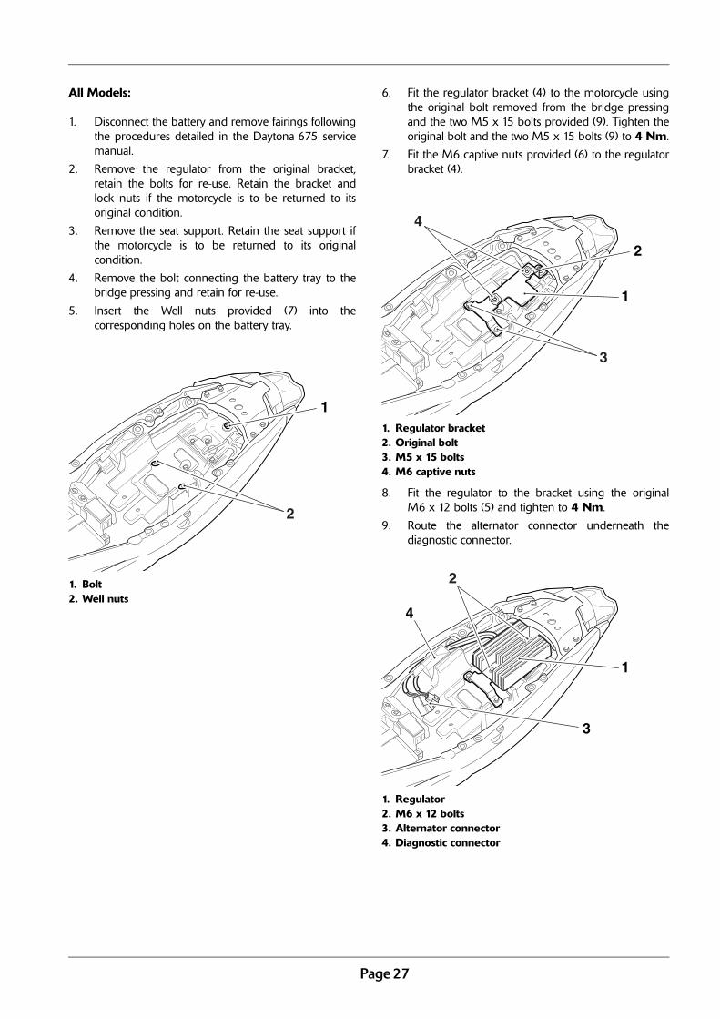
5. Insert the Well nuts provided (7) into thecorresponding holes on the battery tray.
1. Bolt2. Well nuts
6. Fit the regulator bracket (4) to the motorcycle usingthe original bolt removed from the bridge pressingand the two M5 x 15 bolts provided (9). Tighten theoriginal bolt and the two M5 x 15 bolts (9) to 4 Nm.
7. Fit the M6 captive nuts provided (6) to the regulatorbracket (4).
1. Regulator bracket2. Original bolt3. M5 x 15 bolts4. M6 captive nuts
8. Fit the regulator to the bracket using the originalM6 x 12 bolts (5) and tighten to 4 Nm.
9. Route the alternator connector underneath thediagnostic connector.
1. Regulator2. M6 x 12 bolts3. Alternator connector4. Diagnostic connector
2
1
3
1
2
4
1
3
2
4
Page 28
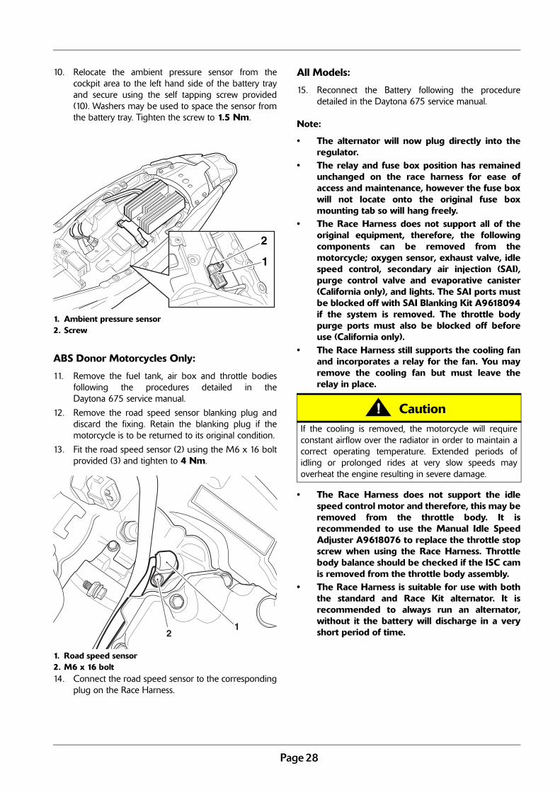
10. Relocate the ambient pressure sensor from thecockpit area to the left hand side of the battery trayand secure using the self tapping screw provided(10). Washers may be used to space the sensor fromthe battery tray. Tighten the screw to 1.5 Nm.
1. Ambient pressure sensor2. Screw
ABS Donor Motorcycles Only:
11. Remove the fuel tank, air box and throttle bodiesfollowing the procedures detailed in theDaytona 675 service manual.
12. Remove the road speed sensor blanking plug anddiscard the fixing. Retain the blanking plug if themotorcycle is to be returned to its original condition.
13. Fit the road speed sensor (2) using the M6 x 16 boltprovided (3) and tighten to 4 Nm.
1. Road speed sensor2. M6 x 16 bolt14. Connect the road speed sensor to the corresponding
plug on the Race Harness.
All Models:
15. Reconnect the Battery following the proceduredetailed in the Daytona 675 service manual.
Note:
• The alternator will now plug directly into theregulator.
• The relay and fuse box position has remainedunchanged on the race harness for ease ofaccess and maintenance, however the fuse boxwill not locate onto the original fuse boxmounting tab so will hang freely.
• The Race Harness does not support all of theoriginal equipment, therefore, the followingcomponents can be removed from themotorcycle; oxygen sensor, exhaust valve, idlespeed control, secondary air injection (SAI),purge control valve and evaporative canister(California only), and lights. The SAI ports mustbe blocked off with SAI Blanking Kit A9618094if the system is removed. The throttle bodypurge ports must also be blocked off beforeuse (California only).
• The Race Harness still supports the cooling fanand incorporates a relay for the fan. You mayremove the cooling fan but must leave therelay in place.
• The Race Harness does not support the idlespeed control motor and therefore, this may beremoved from the throttle body. It isrecommended to use the Manual Idle SpeedAdjuster A9618076 to replace the throttle stopscrew when using the Race Harness. Throttlebody balance should be checked if the ISC camis removed from the throttle body assembly.
• The Race Harness is suitable for use with boththe standard and Race Kit alternator. It isrecommended to always run an alternator,without it the battery will discharge in a veryshort period of time.
1
2
12
CautionIf the cooling is removed, the motorcycle will requireconstant airflow over the radiator in order to maintain acorrect operating temperature. Extended periods ofidling or prolonged rides at very slow speeds mayoverheat the engine resulting in severe damage.
Page 29
Chassis Parts
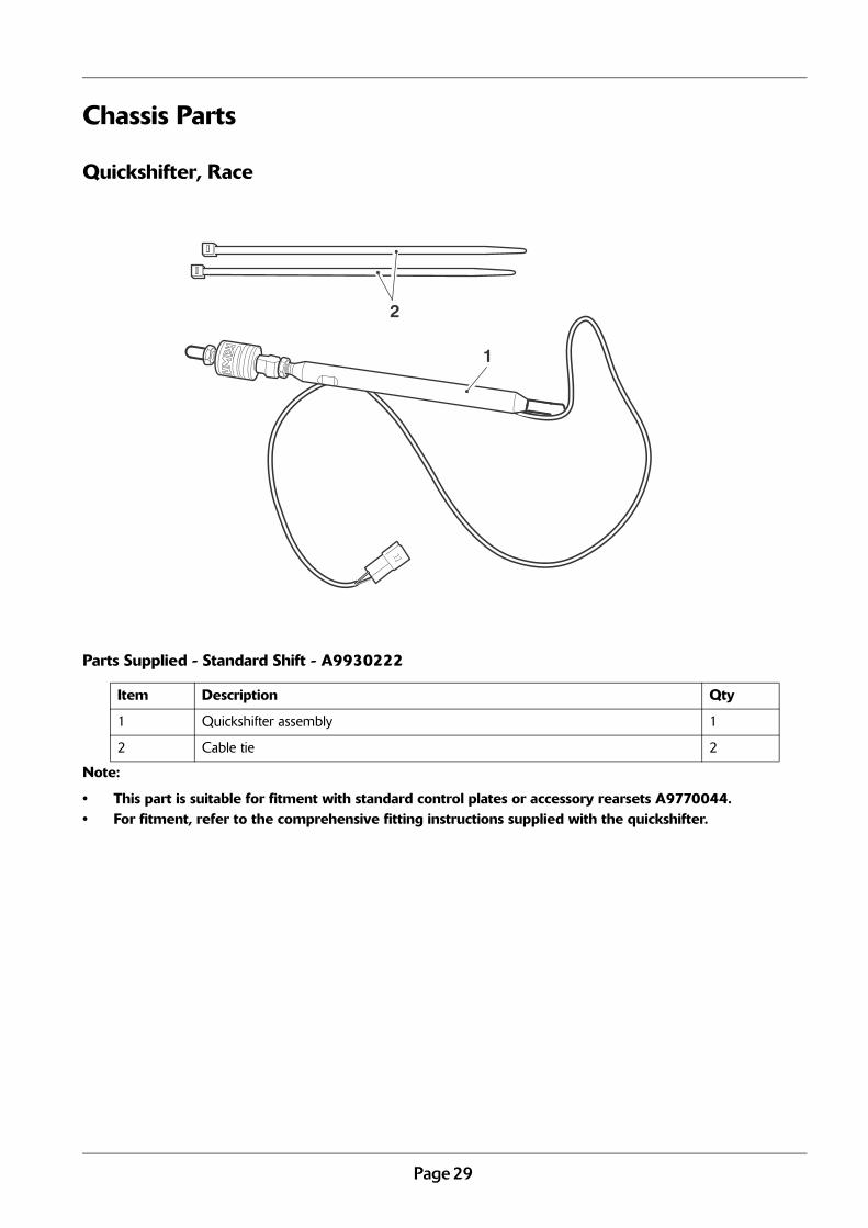
Quickshifter, Race
Parts Supplied - Standard Shift - A9930222
Note:
• This part is suitable for fitment with standard control plates or accessory rearsets A9770044.• For fitment, refer to the comprehensive fitting instructions supplied with the quickshifter.
Item Description Qty
1 Quickshifter assembly 1
2 Cable tie 2
2
1

Page 30
Race Wheel Kit
Parts Supplied - Wheel Kit, Pair, Race - A9648032
Note:
• For fitment refer to the procedures detailed in section 15 of the Daytona 675 service manual.
Item Description Qty
1 Wheel assembly, Front, 17 x MT3.5 1
2 Wheel assembly, Rear, 17 x MT5.5 1
3 Bolt, Disc, M8 x 1.25 x 30, Slv 14
1
2
3
Page 31
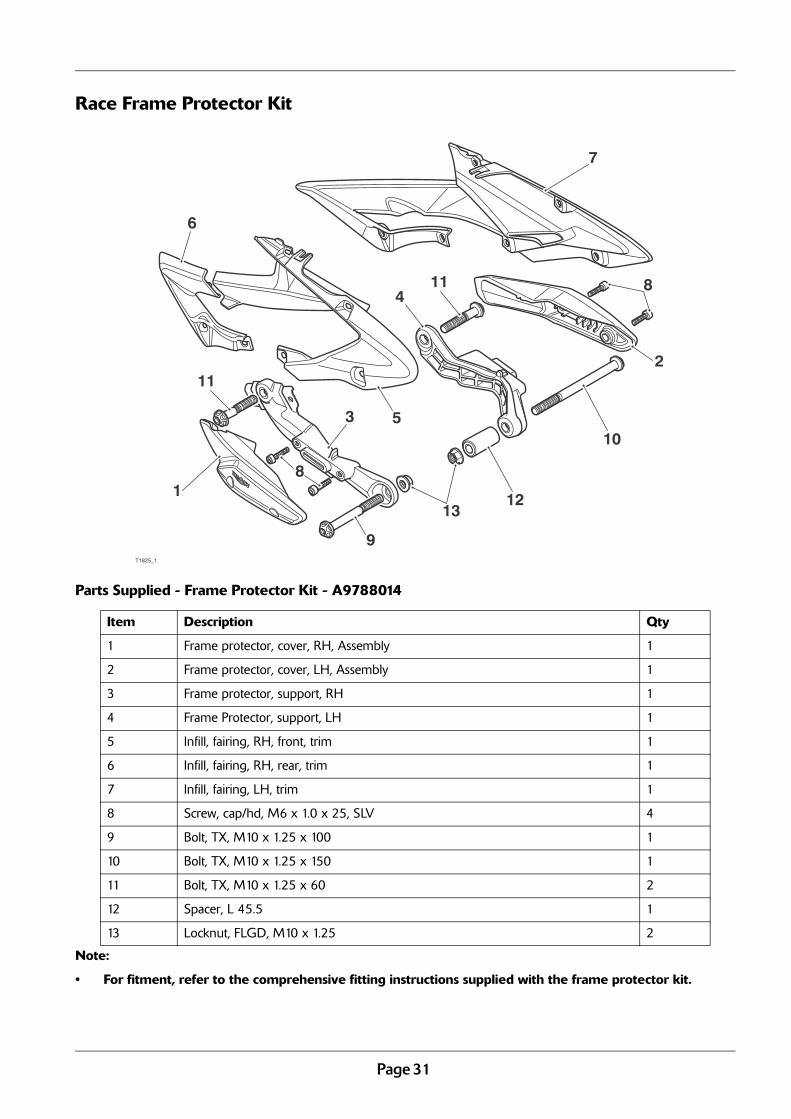
Race Frame Protector Kit
Parts Supplied - Frame Protector Kit - A9788014
Note:
• For fitment, refer to the comprehensive fitting instructions supplied with the frame protector kit.
Item Description Qty
1 Frame protector, cover, RH, Assembly 1
2 Frame protector, cover, LH, Assembly 1
3 Frame protector, support, RH 1
4 Frame Protector, support, LH 1
5 Infill, fairing, RH, front, trim 1
6 Infill, fairing, RH, rear, trim 1
7 Infill, fairing, LH, trim 1
8 Screw, cap/hd, M6 x 1.0 x 25, SLV 4
9 Bolt, TX, M10 x 1.25 x 100 1
10 Bolt, TX, M10 x 1.25 x 150 1
11 Bolt, TX, M10 x 1.25 x 60 2
12 Spacer, L 45.5 1
13 Locknut, FLGD, M10 x 1.25 2
T1825_1
2
1
3
4
7
5
6
8
12
9
10
11
811
13
Page 32
NO WARRANTIES ARE PROVIDED FOR THIS RACING KIT. TRIUMPH MOTORCYCLES DOES NOT PROVIDE ANYWARRANTIES FOR THIS RACING KIT OR FOR ANY OF THE PARTS IN THIS RACING KIT. ALL WARRANTIES,EXPRESS OR IMPLIED, ARE SPECIFICALLY DISCLAIMED. TRIUMPH MOTORCYCLES DOES NOT PROVIDE ANYWARRANTIES OF MERCHANTABILITY OR FITNESS FOR A PARTICULAR PURPOSE. IN NO EVENT SHALLTRIUMPH MOTORCYCLES, ITS RELATED COMPANIES OR UNITED STATES REPRESENTATIVES BE LIABLE FORANY ALLEGED BREACH OF WARRANTIES INCLUDING WARRANTIES OF MERCHANTABILITY OR WARRANTIESOF FITNESS FOR A PARTICULAR PURPOSE. TRIUMPH MOTORCYCLES LTD, ITS RELATED COMPANIES AND ITSREPRESENTATIVES IN THE UNITED STATES, SPECIFICALLY DISCLAIM ALL LIABILITY ARISING OUT OF THE USEOF THIS RACING KIT. IN NO EVENT SHALL TRIUMPH MOTORCYCLES LTD, ITS RELATED COMPANIES OR ITSUNITED STATES REPRESENTATIVES BE LIABLE FOR ANY DAMAGES ARISING OUT OF THE USE OF THIS RACINGKIT. THIS MEANS THAT, IN NO EVENT, SHALL TRIUMPH MOTORCYCLES LTD, ITS RELATED COMPANIES OR ITSUNITED STATES REPRESENTATIVES BE LIABLE FOR ANY GENERAL, INDIRECT OR CONSEQUENTIAL DAMAGESARISING OUT OF THE USE OF THIS RACING KIT.