2011 thermoelectrics applications workshop · 2011 thermoelectrics applications workshop ... •...
TRANSCRIPT

2011 THERMOELECTRICS APPLICATIONS WORKSHOP
Thermoelectrics: From Space Power Systems to Terrestrial Waste Heat Recovery Applications
Jean-Pierre Fleurial, Thierry Caillat, Bill J. Nesmith, Richard C. Ewell, David F. Woerner, Gregory C. Carr and Loren E. Jones
Jet Propulsion Laboratory/California Institute of Technology
San Diego, CaliforniaJanuary 3 - 6, 2011

Outline
• U.S. RTG-powered NASA Science & Exploration Missions
• MMRTG-powered Mars Science Laboratory mission – Overview of power subsystem architecture
• Development of high temperature TE couple technology for next generation RTGs– Need for 2x to 4x improvement in RTG conversion
efficiency and specific power (W/kg)
• Potential of new TE technology for terrestrial applications– High grade waste heat sources
DOE TEAW 01/03/2011 JPF - 2

3
RTG Technology - Missions
Mission RTG TE Destination Launch Year
Mission Length
Transit 4A SNAP-3B7(1) PbTe Earth Orbit 1961 15
Transit 4B SNAP-3B8 (1) PbTe Earth Orbit 1962 9Apollo 12 SNAP-27 RTG (1) PbTe Lunar Surface 1969 8Pioneer 10 SNAP-19 RTG (4) PbTe Outer Planets 1972 34Triad-01-1X SNAP-9A (1) PbTe Earth Orbit 1972 15Pioneer 11 SNAP-19 RTG (4) PbTe Outer Planets 1973 35Viking 1 SNAP-19 RTG (2) PbTe Mars Surface 1975 4Viking 2 SNAP-19 RTG (2) PbTe Mars Surface 1975 6LES 8 MHW-RTG (4) Si-Ge Earth Orbit 1976 15LES 9 MHW-RTG (4) Si-Ge Earth Orbit 1976 15Voyager 1 MHW-RTG (3) Si-Ge Outer Planets 1977 31
Voyager 2 MHW-RTG (3) Si-Ge Outer Planets 1977 31
Galileo GPHS-RTG (2)RHU(120)
Si-Ge Outer Planets 1989 14
Ulysses GPHS-RTG (1) Si-Ge Outer Planets/Sun
1990 18
Cassini GPHS-RTG (3)RHU(117)
Si-Ge Outer Planets 1997 11
New Horizons GPHS-RTG (1) Si-Ge Outer Planets 2005 3 (17)
MSL MMRTG (1) PbTe Mars Surface 2011 3
RTGs have been successfully used on a number of long-life missions
158 We, 4.2 W/kg6.5% EfficiencyDeep space operation30 Year life demonstrated
MHW-RTG
285 We, 5.1 W/kg6.5% EfficiencyDeep space operation> 18 Year life demonstrated
GPHS-RTG
SNAP-19
MMRTG
40 We, 3 W/kg6.3% EfficiencyDeep space and planetarysurface operation30 Year life demonstrated
120 We, 2.8 W/kg6.3% EfficiencyDeep space and planetarysurface operation
PbTe-based SiGe-based
DOE TEAW 01/03/2011 JPF - 3

MMRTG-powered Mars Science Laboratory mission
DOE TEAW 01/03/2011 JPF - 4
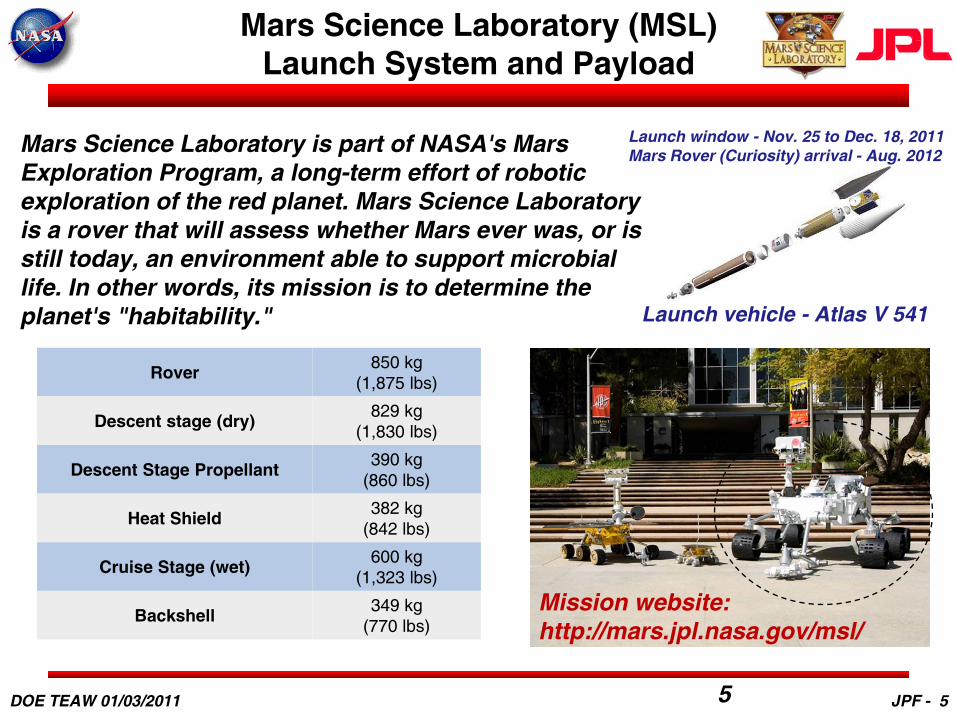
Mars Science Laboratory (MSL)Launch System and Payload
5
Rover 850 kg(1,875 lbs)
Descent stage (dry) 829 kg(1,830 lbs)
Descent Stage Propellant 390 kg(860 lbs)
Heat Shield 382 kg (842 lbs)
Cruise Stage (wet) 600 kg(1,323 lbs)
Backshell 349 kg(770 lbs)
Mars Science Laboratory is part of NASA's Mars Exploration Program, a long-term effort of robotic exploration of the red planet. Mars Science Laboratory is a rover that will assess whether Mars ever was, or is still today, an environment able to support microbial life. In other words, its mission is to determine the planet's "habitability." Launch vehicle - Atlas V 541
Mission website: http://mars.jpl.nasa.gov/msl/
Launch window - Nov. 25 to Dec. 18, 2011Mars Rover (Curiosity) arrival - Aug. 2012
DOE TEAW 01/03/2011 JPF - 5

Cruise Stage
Cruise
Heatshield
Rover(Stowed)Backshell
Sky Crane
Solar Array (SA)
Multi-Mission RadioisotopeThermoelectric Generator (MMRTG)
Secondary Batteries &Power Bus Control
DOE TEAW 01/03/2011

Entry, Descent, and Landing Stage
7
All eight throttleable retrorockets on the descent stage, called Mars Landing Engines (MLE's), begin firing for the powered descent phase
DOE TEAW 01/03/2011 JPF - 7

Surface Stage: MSL Science Instruments
8DOE TEAW 01/03/2011

Overview of MSL Avionics Control Hardware- Power Subsystem Architecture Design Challenges -
• MSL has three stages that share one primary power bus– First time that RTG, Battery and Solar Array elements are on same power bus– Bus stability over various configurations of the vehicle– Large solar array capable of high battery charge currents
• Power system must function nominally in all three stages during all phases of the mission• Descent and Rover stages
are separated with cable cutters and must continue to function
• Varying Power Bus configuration during MSL mission lifetime• Large currents required
throughout the vehicle and delivered to loads
DOE TEAW 01/03/2011 JPF - 9

MSL Power System Configurations
• Cruise configuration– All three stages physically and electrically connected. – Solar Array + MMRTG power supports all loads.
• Entry-Descent-Landing configuration– All three stages electrically separated via mechanical relays opening.
Cruise Stage physically separated and non-functional at this point.– Descent Stage loads powered by thermal batteries. – Rover loads powered by MMRTG + Li-Ion Batteries. – During descent the Rover and Descent Stage are physically separated
• Surface configuration– Descent stage non-functional. – Rover loads are powered by MMRTG + Li-Ion Batteries.
10DOE TEAW 01/03/2011 JPF - 10

MSL Power System Modeling
Power system modeling is performed two ways
• High fidelity predictions using a custom tool called MMPAT.– Multi Mission Power Analysis Tool (MMPAT)
• Uses table based models for power sources– Battery voltage: Function of Temp, Current & state of charge (SOC)– Solar array: test data driven at solar cell level– MMRTG: table based on JPL DEGRA software tool
Tables are accessed through:» Age of Radioisotope Heat Source» Age of Generator since fueling» Generator Fin Root Temperature
• Load power tracked in database style table– Each device has load power states defined in table– Device states are used to simulate mission scenarios
• Simple power system analysis is performed using spreadsheet models
11DOE TEAW 01/03/2011 JPF - 11

12
MMPAT Overview
• Software Simulation of Spacecraft Electrical Power & Thermal Subsystems– Models the behavior of a power source and an energy storage device as they
interact with the spacecraft loads over the mission timeline.
• Models Multiple Mission Types– Planetary Lander, Planetary Orbiter, Heliocentric Orbiter
• Used by Deep Impact (DI), MER, MRO & MSL Flight Projects.– Integrated with APGEN (mission planning tool) for MER & DI Operations
planning
Power Bus
Battery&
Battery Charger
Solar Array
PEL
General Thermal
Solar Thermal
Orbital Dynamics&
Insolation
PlanetaryEnvironment
Shunt Limiter
ThermostaticallyControlled
Heaters
DOE TEAW 01/03/2011 JPF - 12
Surface Phase Bus Voltage Predictions
• Bus voltage during surface follows battery discharge and recharge curves– Unlike Cruise where solar array produces more than enough power to
remain power positive and able to regulate the bus voltage
• Battery performance varies with temperature and discharge rate
• Therefore, bus voltage predictions will vary for similar surface scenarios depending on Martian season and change in load power (usually heaters)
13DOE TEAW 01/03/2011 JPF - 13

MMRTG Power Model WorkshopModeled Seasonal Variation
– Spring• Highest expected MMRTG power output• Highest battery capacity• Average heat energy required
– Summer• Above average MMRTG power output• Above average battery capacity• Lowest heat energy required
– Fall• Below average expected MMRTG power output• Below average battery capacity• Average heat energy required
– Winter• Lowest MMRTG power output• Lowest battery capacity• Highest heat energy required
MMRTG
MM
RTG
Vol
tage
(V)
Rover Surface Time (sols)
~ 33 V
~ 28 V
DOE TEAW 01/03/2011 JPF - 14

Multi-Mission RTG Overview
768 <PbTe + TAGS/PbSnTe> couples
Beginning of Life Performance~ 125 W ~ 2.8 W/kg
• Ability to operate in vacuum and planetary atmospheres– 23-36 V DC capability, series-parallel circuitry
• 17 years lifetime requirement– Up to 3 years of storage and up to 14 years of operation
• Ability to withstand high mechanical loads– ~ 0.3 g2/Hz (random vibrations)– Up to 6000 g (pyrotechnic shock)
DOE TEAW 01/03/2011 JPF - 15

High Temperature TE Couple Technology Developmentfor next generation RTGs
DOE TEAW 01/03/2011 JPF - 16

Impact of Advanced High Temperature Materials onThermoelectric Power Systems for Space Exploration
Ultimate goal: > 15% efficient, 10 We/kg Advanced RTGs
Thot = 1100 K to 1275 K(higher is better!)
Lower System Mass and Conversion Efficiency Needed (x2 to 4)
0
2
4
6
8
10
12
14
0 5 10 15
RTG
Spe
cific
Pow
er (W
/kg)
RTG System Conversion Efficiency (%)
x 3 ImprovementZTave ~ 1.65
ZTave ~ 2.0
x 2 ImprovementZTave ~ 1.14
"GPHS-RTG" Si-GeZTave ~ 0.55
Thot = 1275 KTcold = 575 K
ATEC ZTave ~ 0.80
NASA's Advanced TE Performance Goal
"MMRTG" PbTe/TAGS
ZTave ~ 0.85
Advanced RTG Specific Power vs. System Conversion Efficiency(Based on radiatively coupled vacuum operation unicouple based RTG concept)
y ( )
DOE TEAW 01/03/2011 JPF - 17

High Efficiency = High ZT & Wide ∆T
• Need to combine several TE materials
• Segmenting vs. Cascading – Segmented Thermoelectric• Constrained by constant current
– u = I/Qc ≈ Constant
– Cascaded Thermoelectric• Independent circuits for each stage
– Current different in each stage– Heat different in each leg– u optimized for each stage
Load
p-CeFe4Sb12 n-CoSb3
p-β-Zn4Sb3p-Bi0.4Sb1.6Te3 n-Bi2Te2.95Se0.05300K
475K
975K
675K
I constantQc constant
u = I/Qc constant
Segmented TE Generator
Cascaded TE Generators
I different Qc different
u = I/Qc adjustable
Hot
Cold
n p
i1
R Load,1
n p
R Load,2
i2
I constantQc different
u = I/Qc adjustable
Both methods maximize ZT (efficiency) across wide ∆T, but segmenting has been preferred method for space systems (use couples, not modules)
JPF - 18DOE TEAW 01/03/2011

Thermal/Mechanical Considerations forDevelopment of High Temperature TE Converters
• Critical Structural Integrity Issues–Coefficient of thermal expansion mismatches within TE device stack (including segments), and between stack and heat exchangers (cold and hot “shoes”)
– “Bowing” of TE legs due to large ∆T–Surviving fabrication and assembly steps – and operation
–Typically for space RTGs, only a few cycles (< 20)–Hundreds to thousands for terrestrial applications
DOE TEAW 01/03/2011
Stresses during high temperaturefabrication steps
Stresses back at room temperature after fabrication Stresses when operating across large ∆T
Bonded to hot and cold side heat exchangers
JPF - 19

High Temperature Mechanical Propertiesof TE Materials
Determination of key mechanical properties required for prediction of short and long-term performance of thermoelectric devices: Strength, Stiffness and Toughness
Internal capabilities and external collaborations Types of measurements: flexural (4-point, biaxial),
dynamic modulii, RUS, compression, etc High temperature flexural and modulus
measurements Thermoelectric materials tested to date:
Skutterudites Nanostructured silicon-germanium Yb14MnSb11 (Zintl) and lanthanum telluride Now evaluating advanced PbTe
See 2009 publication for some of the results
Dynamic Young’s Modulus - n-type CoSb3 Young’s modulus at 20°C = 137 - 141 GPa E decreases as T increases, reaching 127 GPa at 400°C
DOE TEAW 01/03/2011 JPF - 20

Projected Performance for Segmented Couple using Current Set of Advanced Materials: Zintl, La3-xTe4 and Skutterudites
• Using current in-house JPL-produced materials– Yb14MnSb11 Zintl, La3-xTe4 and filled skutterudites (SKD)– All materials are produced in 50-100 g batches
• Predicted efficiencies of up to ~ 14%– Fixed temperatures for SKD segments (873 to 473 K)
• 15% efficiency with Advanced PbTe– Hot side couple temperatures from 1073 K to 1273 K
Temperatures Performance
Hot Sidep-type segment
interface
n-type segment interface Cold Side
Device Efficiency
(K) (K) (K) (K) (%)
1273 unsegmented 473 10.2
1273 834 873 473 13.7
1173 837 873 473 12.4
1073 844 873 473 11.2
Cold
nHT pHT
n-leg:La3-xTe4/Filled
Skutterudite
R L
∆T
V
nLT pLT
Hot p-leg:Zintl/Filled Skutterudite
Segmented couple
DOE TEAW 01/03/2011 JPF - 21
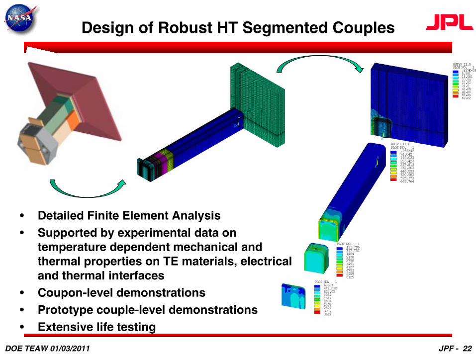
Design of Robust HT Segmented Couples
• Detailed Finite Element Analysis• Supported by experimental data on
temperature dependent mechanical and thermal properties on TE materials, electrical and thermal interfaces
• Coupon-level demonstrations• Prototype couple-level demonstrations • Extensive life testing
DOE TEAW 01/03/2011 JPF - 22

Zintl Leg
La3-xTe4
Leg
Hot Shoe/Heat Collector
Cold Shoes/Heat Sink
Sublimation Control
Couple Configurations in Development
Zintl (Yb14MnSb11) / NanoSiGe Couple (2007-2009)
Zintl (Yb14MnSb11) / La3-xTe4Couple (2009-2010)
P-type Zintl
N-type NanoBulk SiGe
Zintl/SKD // La3-xTe4/SKD Segmented Couple (2010)
Zintl/Adv.PbTe // La3-xTe4/Adv.PbTeSegmented Couple (2011)
p-Zintl with sublimation suppression coating
n-SKD with sublimation suppression coating
n-SKD with sublimation suppression coating
n-La3-xTe4(bare)
ATEC segmented couple (1073K – 473 K operation)
Zintl // La3-xTe4 Cantilevered and Spring-loaded Segmented Couples for Life Performance validation(2012-2014)
DOE TEAW 01/03/2011 JPF - 23

Maturity of Advanced Materials for Potential Infusion into Advanced Converters
Nanostructured Si-Ge (p & n)
14-1-11 Zintl(p)
La3-xTe4(n)
Skutterudite(p & n)
Advanced PbTe(n & p)
Heritage PbTe (n) TAGS (p)
Target ∆T (K) for operation
1273-573 1273-773 1273-773 873-473 773-473 n: 773-473p: 673-473
Average ZT across relevant ∆T
n: 0.73p: 0.55
p: 0.98 n: 0.88 n: 1.01p: 0.78
n: 1.14p: 1.28
n: 0.75p: 1.06
Reproducible TE properties
Scale-up of synthesis (100 g batches)
(15-50 g batches)
(50-100 g batches)
(100-200 g batches)
(30-200 g batches)
(MMRTG Production line)
Thermally stable TE properties
(>12,000 hrs at 1273 K)
(> 12,000 hrs at 1273 K)
(>2,500 hrs at 1273 K)
(>10,000 hrs at 873 K)
(only preliminary data > 300 h)
( 750 K for TAGS, 825 K for PbTe)
Sublimation suppression feasibility demonstrated
(same as heritage SiGe)
(coating, up to 10,000hrs at 1273 K)
(not required up to 1173 K)
(aerogel, up to 9,000hrs at 1273 K)
(Ar atm., assumes same as for heritage PbTe)
(Ar atm., limited to 673 K for TAGS, 825 K for PbTe)
Stable low resistance metallizations
(> 1000h at 1273 K)
(> 5000h at 1273 K)
(> 1000h at 1273 K)
(>1500h at 873 K)
(baseline is heritage PbTe)
(> 200,000 hrs)
Temperature dependent mechanical properties
CTE: 4.5 ppm
CTE: 16-19 ppm
CTE: 17-20 ppm
CTE: 12-14 ppm
CTE: 19-21 ppm
CTE: 19-21 ppm
DOE TEAW 01/03/2011JPF - 24

Yb14MnSb11/Nanobulk Si0.8Ge0.2 & Yb14MnSb11/La3-xTe4HT TE Couple Technology Development
0.0
0.2
0.4
0.6
0.8
1.0
1.2
1.4
1.6
200 300 400 500 600 700 800 900 10001100120013001400
ZT
T(K)
Average Yb14MnSb11 ball-milledYMS1002-3 6months at 1273KYMS 998-3 6months at 1273K
1.00E-07
1.00E-06
1.00E-05
1.00E-04
1.00E-03
1.00E-02
0 2000 4000 6000 8000
Subl
imat
ion
rate
(g/
cm2/
hr)
Time (hr)
Uncoated Zintl
Sublimation rate goal
Powder Metallurgy Synthesis Scale-up and Reproducible TE properties
Thermal Stability of TE Materials and Low Electrical Contact Resistance Metallizations
y = -0.7883x + 0.2597
0.1
0.15
0.2
0.25
0.3
-0.05 0 0.05 0.1 0.15 0.2
Travel (cm)R
esis
tan
ce (
mo
hm
. cm
2)
0.0
0.2
0.4
0.6
0.8
1.0
1.2
1.4
1.6
200 300 400 500 600 700 800 900 1000 1100 1200 1300
ZT
T (K)
LTP6-3
LTP6-4
LTP12-3
LTP13-3
LTP18-2
MA La3-xTe4
6-month stability of Zintl at 1275 K
Metallized Leg Fabrication
La3-xTe4Filled SkutteruditesYb14MnSb11 Zintl
2-month stability of Zintl Metallization at 1275 K
18-month stability of Zintl Sublimation Barrier Coating at 1275 K
DOE TEAW 01/03/2011 JPF - 25

DOE TEAW 01/03/2011
ATEC Segmented Couples ~ 11% Efficiency(Zintl/LaTe/SKD segmented couple testing – Thot = 1073K)
p-Zintl with sublimation suppression coating
n-SKD with sublimation suppression coating
n-SKD with sublimation suppression coating
n-La3-xTe4(bare)
ATEC segmented couple (1073K – 473 K operation)
•Assembled several couples•Long life operation at 800 C predicted
• Testing was initiated in late 2010(600 hours of test to date, stable performance)
• Internal device resistance within 2% of predict• Open circuit voltage within 9% of predict• ~ 11% couple conversion efficiency
0
100
200
300
400
500
600
700
800
900
1000
0
50
100
150
200
250
0 1 2 3 4 5 6 7 8 9 10 11 12
P (m
W)
E (m
V)
I (A)
800 C (overall), 1 day
E (mV)
P (mW)
70
75
80
85
90
95
100
105
110
0 100 200 300 400 500 600
Sust
aine
d po
wer
rati
o (P
/Po)
(%)
Time (hour)
Maximum Power Output vs. Time
ATEC couple 4 (overall)
ATEC couple 4 (p-leg)
ATEC couple 4 (n-leg)
JPF - 26

14-15% Efficient Segmented Couple Demonstration
• Completed beginning-of-life performance test of 1275 K segmented couple
– First demonstration of segmented couple across full temperature range of interest• Spring loaded configuration (similar to MMRTG TE converter)
• Legs sized for operation at 1273 K
• Uses Yb14MnSb11 (Zintl) and La3-xTe4 for high temperature segments
• Uses filled skutterudites for “low” temperature segments
• ~ 15% efficiency achieved with cold side temperature of 453 K
– Excellent agreement between experimental and predicted performance• Internal resistance within 1%, open circuit voltage within 1.5%
• Maximum power output within 3%
High Temperature Segmented Zintl/La3-xTe4/SKD Couple Spring-loaded Performance Test Configuration
Beginning-of-Life (BOL)Experimental vs. Predicted I-V and I-P curves
For Advanced TE Couple
14-1-11 Zintl
La3-xTe4
Double-filledn-SKDNear
fully-filledp-SKD 0
200
400
600
800
1000
1200
1400
1600
1800
0
50
100
150
200
250
300
350
0 2 4 6 8 10 12 14 16
Pow
er (m
W)
Volt
age
(mV
)Current (A)
Voltage
Power
Prediction
p-leg: 14-1-11 Zintl/SKDn-leg: La3-xTe4/SKDThot ~ 1273 KTcold ~ 373 KEfficiency ~ 15.3%
DOE TEAW 01/03/2011 JPF - 27

Potential for Terrestrial High GradeWaste Heat Recovery Applications
DOE TEAW 01/03/2011 JPF - 28

Some “Large Scale” Opportunities for High Grade Waste Heat Recovery TE Power Systems
• Thermoelectrics cannot compete “head-on” with dynamic technologies, but…
• …Some industrial processes are potentially attractive for TE systems
• For near term applications in the US alone, between 0.9 and 2.8 TWh of electricity might be produced each year for materials with average ZT values ranging from 1 to 2– Medium to high grade heat for aluminum, glass,
metal casting, non-metal melting, ceramic sintering and steel manufacturing
– Thot > 1000 K– Limited opportunity to reuse the waste heat to
improve process end-to-end efficiency – Difficulties in effectively transporting that heat to
separate energy conversion systems TE as a “passive “heat exchanger system in a
stationary WHR system (no mass constraint!! fewer thermal cycles!)
Fluid Heating
Curing & Forming
Drying
Non-metal MeltingDistillation
Columns & Boilers
Steel SmeltingMetal and Non-metal Heating
AluminumMelting & Smelting
Smelting
Agglomeration/Sintering
Metal Heat Treating
Thermal Oxidizers
Calcining
400 K 1900 K1200 K
Automobile Exhaust
Adapted from: Hendricks, T., Choate, W. T., Industrial Technologies Program, “Engineering Scoping Study of Thermoelectric Generator Systems for Industrial Waste Heat Recovery” (U.S. Department of Energy, 1-76, 2006).
Same need for ZTaveof 1.5 to 2- Lower temperatures- But mass & volume
constraints- 1000s of thermal cycles
JPF - 29

TE systems for High Power Applications – NASA perspective
Nuclear Electric Propulsion for Space Exploration Science Missions• Technology development was focused on arrays of thermoelectric couples grouped
into power converter assemblies• Used liquid metal heat exchangers to interface with reactor heat source and radiator
heat sinks
ALIPGSA
ColdSecondary
HotSecondary
PCATCA PCSTE Module
Thermoelectric Converter Assembly
Power Converter Assembly
Hot side liquidmetal HX inlet
Hot side liquidmetal HX outlet
Cold side liquidmetal HX outlet
Cold side liquidmetal HX outlet
Cold side liquidmetal HX inlet
Cold side liquidmetal HX inlet
Cold side HX
Cold side HX
Hot side HXSTMC Elements
Sapphire insulator
Development of robust high temperature thermoelectric module technology is critical to all applications• Using low cost, practical fabrication
techniques and relatively inexpensive materials (including thermoelectrics)• Ability to integrate with various heat
exchangers• Ability to reliably survive thermal/mechanical
stresses
DOE TEAW 01/03/2011 JPF - 30

Assembly and Test of Aerogel-FilledSkutterudite TE Modules
Stacked & Aligned Components
Die Fixture
Assembled 2x4 Module after bonding cycle and egg-crate vaporized
Module Technologies Developed under NASA/SMDIn-Space Propulsion Program in 2004-2005 250W Heater
Mo Calorimeter
SS 304 Calorimeter
Water-cooled Cu Heat sink
LT-TMC
LT-TMC
0.0
0.2
0.4
0.6
0.8
1.0
1.2
0 5 10 15 20Iout (A)
Pout
(W)
0
15
30
45
60
75
90
105
120
135
150
165
180
Vout
(mV)
Power - Experimental
Power - Prediction
Voltage - Experimental
Performance Test
Designed for integration with flat plate HXs
DOE TEAW 01/03/2011 JPF - 31

Summary and Conclusions
• Thermoelectrics have unique advantages for integration into selected high temperature waste heat recovery applications
– TWh-class opportunities available for some energy intensive industrial processes• TE materials efficiency is critical to TEG performance:
– x 2 to 3 increase in ZTave needed, especially for low to medium grade waste heat– But cost, environmental friendliness and availability are also key parameters (potential issues with
elements such as Ge, Pb, Tl)– Terrestrial technology to date has used some form of encapsulation for the TE converters (no air
operation) which reliability has been proven• Most of the technology risk lies in development of rugged TE couple & modular devices
and is a must to enable new applications– Without life, high ZT does not matter!– High temperature TE device development requires considerable, sustained support
• Converter & heat exchanger designs are critical to efficient system implementation– Typical heat fluxes delivered to the TE devices is in 5-30 W/cm2 range– Efficient operation under large ∆T requires leg height > 5-10 mm
• Demonstrated 10% to 15% efficient new high temperature couples based on new TE materials developed in last 5-10 years
– Extended performance testing and lifetime validation still require extensive work– Now developing segmented couples for more efficient next generation converters
DOE TEAW 01/03/2011 JPF - 32

Acknowledgments
• Part of this work was performed at the Jet Propulsion Laboratory, California Institute of Technology under contract with the National Aeronautics and Space Administration
• Part of this work has been supported by the Office of Naval Research, the Defense Advanced Research Project Agency and the Department of Energy
• The work presented here benefited from contributions from a number of collaborators in the past few years– California Institute of Technology– University of California at Los Angeles, University of California at Davis– California State Polytechnic University, Pomona– Ole Miss, University of Southern California– Boston College, Massachusetts Institute of Technology – Michigan State University– Teledyne Energy Systems– HS Rocketdyne
DOE TEAW 01/03/2011 JPF - 33
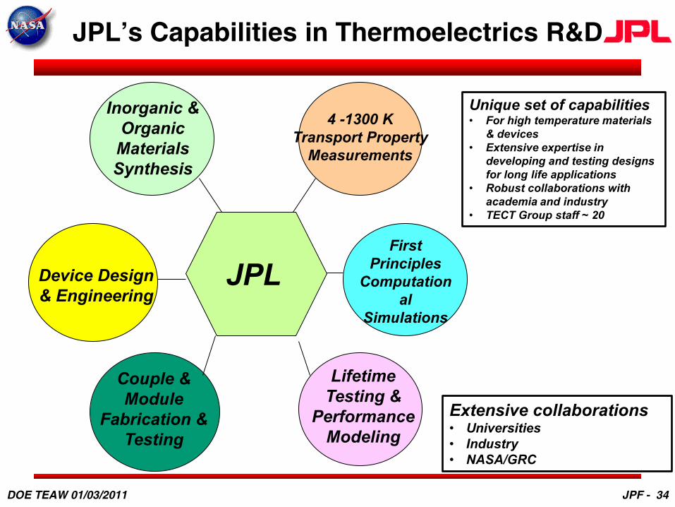
JPL’s Capabilities in Thermoelectrics R&D
Inorganic & Organic Materials Synthesis
4 -1300 KTransport Property
Measurements
First Principles
Computational
Simulations
Lifetime Testing &
Performance Modeling
Couple & Module
Fabrication & Testing
JPLDevice Design & Engineering
Unique set of capabilities• For high temperature materials
& devices• Extensive expertise in
developing and testing designs for long life applications
• Robust collaborations with academia and industry
• TECT Group staff ~ 20
Extensive collaborations• Universities• Industry• NASA/GRC
DOE TEAW 01/03/2011 JPF - 34