2006 cadillac escalade ext owner manual...
TRANSCRIPT

Seats and Restraint Systems ........................... 1-1Front Seats ............................................... 1-2Rear Seats ............................................... 1-7Safety Belts .............................................. 1-8Child Restraints ....................................... 1-27Airbag System ......................................... 1-52Restraint System Check ............................ 1-66
Features and Controls ..................................... 2-1Keys ........................................................ 2-3Doors and Locks ....................................... 2-8Windows ................................................. 2-21Theft-Deterrent Systems ............................ 2-23Starting and Operating Your Vehicle ........... 2-25Mirrors .................................................... 2-38OnStar® System ...................................... 2-46Universal Home Remote System ................ 2-48Storage Areas ......................................... 2-53Sunroof .................................................. 2-73Vehicle Personalization ............................. 2-74
Instrument Panel ............................................. 3-1Instrument Panel Overview .......................... 3-4Climate Controls ...................................... 3-22Warning Lights, Gages, and Indicators ........ 3-28Driver Information Center (DIC) .................. 3-45Audio System(s) ....................................... 3-63
Driving Your Vehicle ....................................... 4-1Your Driving, the Road, and Your Vehicle ........ 4-2Towing ................................................... 4-50
Service and Appearance Care .......................... 5-1Service ..................................................... 5-3Fuel ......................................................... 5-5Checking Things Under the Hood ............... 5-10All-Wheel Drive ........................................ 5-45Rear Axle ............................................... 5-46Front Axle ............................................... 5-47Headlamp Aiming ..................................... 5-48Bulb Replacement .................................... 5-52Windshield Wiper Blade Replacement ......... 5-59Tires ...................................................... 5-60Appearance Care ................................... 5-100Vehicle Identification ............................... 5-108Electrical System .................................... 5-109Capacities and Specifications ................... 5-119
Maintenance Schedule ..................................... 6-1Maintenance Schedule ................................ 6-2
Customer Assistance and Information .............. 7-1Customer Assistance and Information ........... 7-2Reporting Safety Defects ........................... 7-13
Index ................................................................ 1
2006 Cadillac Escalade EXT Owner Manual M
Information Provided by:
GENERAL MOTORS, GM, the GM Emblem, CADILLAC,the CADILLAC Crest & Wreath, and the namesESCALADE and EXT are registered trademarks ofGeneral Motors Corporation.
This manual includes the latest information at the time itwas printed. We reserve the right to make changesafter that time without notice. For vehicles first sold inCanada, substitute the name “General Motors of CanadaLimited” for Cadillac Motor Car Division whenever itappears in this manual.
Keep this manual in the vehicle, so it will be there if it isever needed while you are on the road. If the vehicleis sold, leave this manual in the vehicle.
Canadian OwnersA French language copy of this manual can be obtainedfrom your dealer or from:
Helm, IncorporatedP.O. Box 07130Detroit, MI 48207
How to Use This ManualMany people read the owner manual from beginning toend when they first receive their new vehicle. If thisis done, it can help you learn about the featuresand controls for the vehicle. Pictures and words worktogether in the owner manual to explain things.
Litho in U.S.A.Part No. 06ESCALEXT A First Printing ©2005 General Motors Corporation. All Rights Reserved.
iiInformation Provided by:

IndexA good place to quickly locate information about thevehicle is the Index in the back of the manual. It is analphabetical list of what is in the manual and thepage number where it can be found.
Safety Warnings and SymbolsThere are a number of safety cautions in this book.We use a box and the word CAUTION to tell aboutthings that could hurt you if you were to ignorethe warning.
{CAUTION:
These mean there is something that could hurtyou or other people.
In the caution area, we tell you what the hazard is.Then we tell you what to do to help avoid or reducethe hazard. Please read these cautions. If you do not,you or others could be hurt.
You will also find a circlewith a slash through it inthis book. This safetysymbol means “Do Not,”“Do Not do this” or“Do Not let this happen.”
iiiInformation Provided by:
Vehicle Damage WarningsAlso, in this manual you will find these notices:
Notice: These mean there is something that coulddamage your vehicle.
A notice tells about something that can damage thevehicle. Many times, this damage would not be coveredby your vehicle’s warranty, and it could be costly.But the notice will tell what to do to help avoidthe damage.
When you read other manuals, you might seeCAUTION and NOTICE warnings in different colorsor in different words.
There are also warning labels on the vehicle.They use the same words, CAUTION or NOTICE.
Vehicle SymbolsThe vehicle has components and labels that usesymbols instead of text. Symbols are shown along withthe text describing the operation or informationrelating to a specific component, control, message,gage, or indicator.
If you need help figuring out a specific name of acomponent, gage, or indicator, reference thefollowing topics:
• Seats and Restraint Systems in Section 1
• Features and Controls in Section 2
• Instrument Panel Overview in Section 3
• Climate Controls in Section 3
• Warning Lights, Gages, and Indicators in Section 3
• Audio System(s) in Section 3
• Engine Compartment Overview in Section 5
ivInformation Provided by:
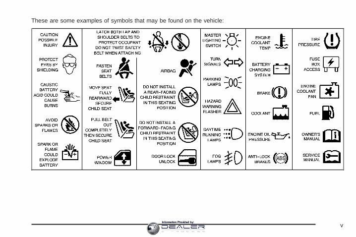
These are some examples of symbols that may be found on the vehicle:
vInformation Provided by:

✍ NOTES
viInformation Provided by:

Front Seats ......................................................1-2Power Seats ..................................................1-2Power Lumbar ...............................................1-3Heated Seats .................................................1-4Reclining Seatbacks ........................................1-5Head Restraints .............................................1-6
Rear Seats .......................................................1-7Rear Seat Operation .......................................1-7
Safety Belts .....................................................1-8Safety Belts: They Are for Everyone .................1-8Questions and Answers About Safety Belts ......1-13How to Wear Safety Belts Properly .................1-14Driver Position ..............................................1-14Safety Belt Use During Pregnancy ..................1-21Right Front Passenger Position .......................1-22Rear Seat Passengers ..................................1-22Rear Safety Belt Comfort Guides ....................1-25Safety Belt Extender .....................................1-26
Child Restraints .............................................1-27Older Children ..............................................1-27Infants and Young Children ............................1-30Child Restraint Systems .................................1-33
Where to Put the Restraint .............................1-38Lower Anchors and Tethers for
Children (LATCH) ......................................1-39Securing a Child Restraint in a
Rear Seat Position ....................................1-46Securing a Child Restraint in the
Right Front Seat Position ............................1-48Airbag System ...............................................1-52
Where Are the Airbags? ................................1-54When Should an Airbag Inflate? .....................1-57What Makes an Airbag Inflate? .......................1-58How Does an Airbag Restrain? .......................1-58What Will You See After an Airbag Inflates? ........1-59Passenger Sensing System ............................1-60Servicing Your Airbag-Equipped Vehicle ...........1-64Adding Equipment to Your Airbag-Equipped
Vehicle ....................................................1-65
Restraint System Check ..................................1-66Checking the Restraint Systems ......................1-66Replacing Restraint System Parts
After a Crash ............................................1-67
Section 1 Seats and Restraint Systems
1-1Information Provided by:
Front Seats
Power Seats
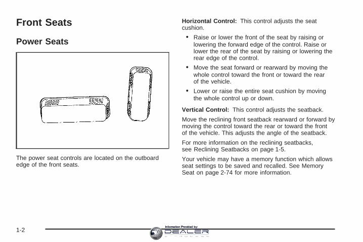
The power seat controls are located on the outboardedge of the front seats.
Horizontal Control: This control adjusts the seatcushion.
• Raise or lower the front of the seat by raising orlowering the forward edge of the control. Raise orlower the rear of the seat by raising or lowering therear edge of the control.
• Move the seat forward or rearward by moving thewhole control toward the front or toward the rearof the vehicle.
• Lower or raise the entire seat cushion by movingthe whole control up or down.
Vertical Control: This control adjusts the seatback.
Move the reclining front seatback rearward or forward bymoving the control toward the rear or toward the frontof the vehicle. This adjusts the angle of the seatback.
For more information on the reclining seatbacks,see Reclining Seatbacks on page 1-5.
Your vehicle may have a memory function which allowsseat settings to be saved and recalled. See MemorySeat on page 2-74 for more information.
1-2Information Provided by:

Power LumbarYour vehicle’s seats may be equipped with powerlumbar.
You can increase ordecrease lumbar supportin an area of the lowerseatback with this control,located on the outboardsides of the front seat(s).
To increase support, press and hold the front of thecontrol. To decrease support, press and hold the rearof the control. Let go of the control when the lowerseatback reaches the desired level of support.
You can also reshape the side wing area of the lowerseatback for more lateral support.
To increase support, press and hold the top of thecontrol. To decrease support, press and hold the bottomof the control. Let go of the control when the lowerseatback reaches the desired level of support.
Your vehicle may have a memory function which allowsseat settings to be saved and recalled. See MemorySeat on page 2-74 for more information.
1-3Information Provided by:

Heated Seats
The buttons used tocontrol this feature arelocated on the front doors.The engine must berunning for the heatedseats to work.
To heat the entire seat, press the horizontal button withthe heated seat and seatback symbol. Press the button tocycle through the temperature settings of high, mediumand low and to turn the heated seat off. Indicator lightswill be lit to designate the level of heat selected: three forhigh, two for medium, and one for low.
To heat only the seatback, press the vertical button withthe heated seatback symbol. An indicator light on theseatback button will be lit to designate that only theseatback is being heated. Additional presses ofthe seatback button will cycle through the heat levels forthe seatback only. Press the horizontal button againto heat the whole seat.
The heated front seats will be canceled after the ignitionis turned off. If you still want to use the heated frontseat feature after you restart your vehicle, you will needto press the heated seat button again.
1-4Information Provided by:

Reclining SeatbacksThe front seats have a recline feature which is describedearlier. See Power Seats on page 1-2.
{CAUTION:
Sitting in a reclined position when your vehicleis in motion can be dangerous. Even if youbuckle up, your safety belts cannot do theirjob when you are reclined like this.
The shoulder belt cannot do its job. In a crash,you could go into it, receiving neck or otherinjuries.
The lap belt cannot do its job either. In a crashthe belt could go up over your abdomen.The belt forces would be there, not at yourpelvic bones. This could cause seriousinternal injuries.
For proper protection when the vehicle isin motion, have the seatback upright.Then sit well back in the seat and wearyour safety belt properly.
Do not have a seatback reclined if your vehicle is moving.
1-5Information Provided by:
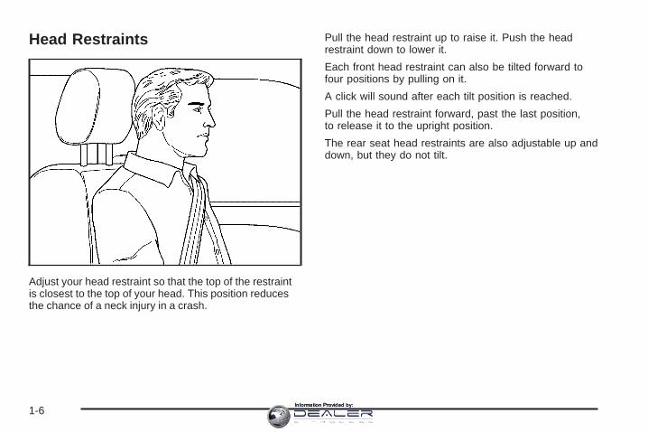
Head Restraints
Adjust your head restraint so that the top of the restraintis closest to the top of your head. This position reducesthe chance of a neck injury in a crash.
Pull the head restraint up to raise it. Push the headrestraint down to lower it.
Each front head restraint can also be tilted forward tofour positions by pulling on it.
A click will sound after each tilt position is reached.
Pull the head restraint forward, past the last position,to release it to the upright position.
The rear seat head restraints are also adjustable up anddown, but they do not tilt.
1-6Information Provided by:

Rear Seats
Rear Seat OperationThe rear seat is a 60/40 split bench seat that can befolded to give you more cargo space and access to thefolding midgate. See Midgate® on page 2-11 formore information on operation of the folding midgate.
To fold either side of the seat do the following:
1. Push the rear seat head restraints all the way down.
2. Pull the seat looplocated where theseatback andseat cushion meet.The seat cushion willrelease and allowyou to tilt it toward thefront of the vehicle.
3. Fold the seatback forward until it is flat. You mayhave to move the front seats forward slightly todo this.
4. Repeat the procedure for the other side.
1-7Information Provided by:
To return the seats to the normal position, push theseatback up and fold the seat cushion down.
{CAUTION:
If the seatback is not locked, it could moveforward in a sudden stop or crash. That couldcause injury to the person sitting there. Alwaysbe sure to press the rear of the seat cushiondown. This action locks the seatback in place.
Push and pull on the seatback to make sure it is locked.Raise the head restraint.
{CAUTION:
A safety belt that is improperly routed, notproperly attached, or twisted will not providethe protection needed in a crash. The personwearing the belt could be seriously injured.After raising the rear seatback, always checkto be sure that the safety belts are properlyrouted and attached, and are not twisted.
Safety Belts
Safety Belts: They Are for EveryoneThis part of the manual tells you how to use safetybelts properly. It also tells you some things you shouldnot do with safety belts.
{CAUTION:
Do not let anyone ride where he or she cannotwear a safety belt properly. If you are in acrash and you are not wearing a safety belt,your injuries can be much worse. You can hitthings inside the vehicle or be ejected from it.You can be seriously injured or killed. In thesame crash, you might not be, if you arebuckled up. Always fasten your safety belt,and check that your passengers’ belts arefastened properly too.
1-8Information Provided by:
{CAUTION:
It is extremely dangerous to ride in a cargoarea, inside or outside of a vehicle. In acollision, people riding in these areas are morelikely to be seriously injured or killed. Do notallow people to ride in any area of your vehiclethat is not equipped with seats and safetybelts. Be sure everyone in your vehicle is in aseat and using a safety belt properly.
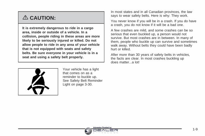
Your vehicle has a lightthat comes on as areminder to buckle up.See Safety Belt ReminderLight on page 3-30.
In most states and in all Canadian provinces, the lawsays to wear safety belts. Here is why: They work.
You never know if you will be in a crash. If you do havea crash, you do not know if it will be a bad one.
A few crashes are mild, and some crashes can be soserious that even buckled up, a person would notsurvive. But most crashes are in between. In many ofthem, people who buckle up can survive and sometimeswalk away. Without belts they could have been badlyhurt or killed.
After more than 30 years of safety belts in vehicles,the facts are clear. In most crashes buckling updoes matter...a lot!
1-9Information Provided by:
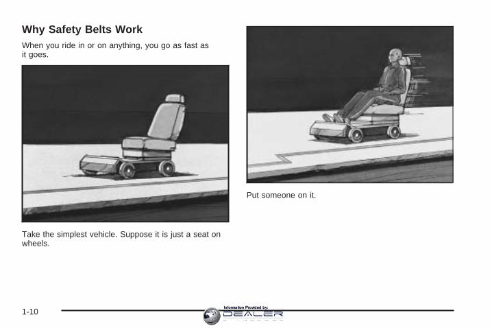
Why Safety Belts WorkWhen you ride in or on anything, you go as fast asit goes.
Take the simplest vehicle. Suppose it is just a seat onwheels.
Put someone on it.
1-10Information Provided by:
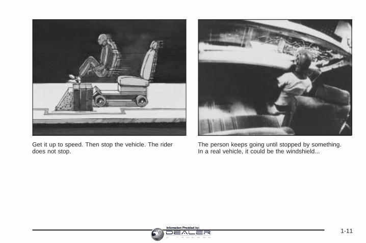
Get it up to speed. Then stop the vehicle. The riderdoes not stop.
The person keeps going until stopped by something.In a real vehicle, it could be the windshield...
1-11Information Provided by:

or the instrument panel... or the safety belts!
With safety belts, you slow down as the vehicle does.You get more time to stop. You stop over more distance,and your strongest bones take the forces. That is whysafety belts make such good sense.
1-12Information Provided by:

Questions and Answers AboutSafety Belts
Q: Will I be trapped in the vehicle after an accidentif I am wearing a safety belt?
A: You could be — whether you are wearing a safetybelt or not. But you can unbuckle a safety belt,even if you are upside down. And your chance ofbeing conscious during and after an accident,so you can unbuckle and get out, is much greaterif you are belted.
Q: If my vehicle has airbags, why should I have towear safety belts?
A: Airbags are in many vehicles today and will bein most of them in the future. But they aresupplemental systems only; so they work withsafety belts — not instead of them. Every airbagsystem ever offered for sale has required the use ofsafety belts. Even if you are in a vehicle that hasairbags, you still have to buckle up to get the mostprotection. That is true not only in frontal collisions,but especially in side and other collisions.
Q: If I am a good driver, and I never drive far fromhome, why should I wear safety belts?
A: You may be an excellent driver, but if you are in anaccident — even one that is not your fault — youand your passengers can be hurt. Being a gooddriver does not protect you from things beyond yourcontrol, such as bad drivers.
Most accidents occur within 25 miles (40 km) ofhome. And the greatest number of seriousinjuries and deaths occur at speeds of less than40 mph (65 km/h).
Safety belts are for everyone.
1-13Information Provided by:

How to Wear Safety Belts ProperlyThis part is only for people of adult size.
Be aware that there are special things to know aboutsafety belts and children. And there are different rules forsmaller children and babies. If a child will be riding in yourvehicle, see Older Children on page 1-27 or Infants andYoung Children on page 1-30. Follow those rules foreveryone’s protection.
First, you will want to know which restraint systems yourvehicle has.
We will start with the driver position.
Driver Position
Lap-Shoulder BeltThe driver has a lap-shoulder belt. Here is how to wearit properly.
1. Close and lock the door.
2. Adjust the seat so you can sit up straight. To seehow, see “Seats” in the Index.
3. Pick up the latch plate and pull the belt across you.Do not let it get twisted.The shoulder belt may lock if you pull the beltacross you very quickly. If this happens, let the beltgo back slightly to unlock it. Then pull the beltacross you more slowly.
4. Push the latch plate into the buckle until it clicks.Pull up on the latch plate to make sure it is secure.If the belt is not long enough, see Safety BeltExtender on page 1-26.Make sure the release button on the buckle ispositioned so you would be able to unbuckle thesafety belt quickly if you ever had to.
1-14Information Provided by:

5. To make the lap part tight, pull up on theshoulder belt.
The lap part of the belt should be worn low and snug onthe hips, just touching the thighs. In a crash, this appliesforce to the strong pelvic bones. And you would be lesslikely to slide under the lap belt. If you slid under it, thebelt would apply force at your abdomen. This could causeserious or even fatal injuries. The shoulder belt should goover the shoulder and across the chest. These parts ofthe body are best able to take belt restraining forces.
The safety belt locks if there is a sudden stop or crash,or if you pull the belt very quickly out of the retractor.
1-15Information Provided by:

Q: What is wrong with this?
A: The shoulder belt is too loose. It will not give nearlyas much protection this way.
{CAUTION:
You can be seriously hurt if your shoulder beltis too loose. In a crash, you would moveforward too much, which could increase injury.The shoulder belt should fit against your body.
1-16Information Provided by:

Q: What is wrong with this?
A: The belt is buckled in the wrong place.
{CAUTION:
You can be seriously injured if your belt isbuckled in the wrong place like this. In acrash, the belt would go up over yourabdomen. The belt forces would be there, notat the pelvic bones. This could cause seriousinternal injuries. Always buckle your belt intothe buckle nearest you.
1-17Information Provided by:

Q: What is wrong with this?
A: The belt is over an armrest.
{CAUTION:
You can be seriously injured if your belt goesover an armrest like this. The belt would bemuch too high. In a crash, you can slide underthe belt. The belt force would then be appliedat the abdomen, not at the pelvic bones, andthat could cause serious or fatal injuries.Be sure the belt goes under the armrests.
1-18Information Provided by:

Q: What is wrong with this?
A: The shoulder belt is worn under the arm. It shouldbe worn over the shoulder at all times.
{CAUTION:
You can be seriously injured if you wear theshoulder belt under your arm. In a crash, yourbody would move too far forward, which wouldincrease the chance of head and neck injury.Also, the belt would apply too much force tothe ribs, which are not as strong as shoulderbones. You could also severely injure internalorgans like your liver or spleen.
1-19Information Provided by:

Q: What is wrong with this?
A: The belt is twisted across the body.
{CAUTION:
You can be seriously injured by a twisted belt.In a crash, you would not have the full widthof the belt to spread impact forces. If a beltis twisted, make it straight so it can workproperly, or ask your dealer to fix it.
1-20Information Provided by:

To unlatch the belt, just push the button on the buckle.The belt should go back out of the way.
Before you close the door, be sure the belt is out ofthe way. If you slam the door on it, you can damageboth the belt and your vehicle.
Safety Belt Use During PregnancySafety belts work for everyone, including pregnantwomen. Like all occupants, they are more likely to beseriously injured if they do not wear safety belts.
A pregnant woman should wear a lap-shoulder belt, andthe lap portion should be worn as low as possible,below the rounding, throughout the pregnancy.
The best way to protect the fetus is to protect the mother.When a safety belt is worn properly, it is more likely thatthe fetus will not be hurt in a crash. For pregnant women,as for anyone, the key to making safety belts effective iswearing them properly.
1-21Information Provided by:

Right Front Passenger PositionTo learn how to wear the right front passenger’s safetybelt properly, see Driver Position on page 1-14.
The right front passenger’s safety belt works the sameway as the driver’s safety belt — except for one thing.If you ever pull the shoulder portion of the belt out all theway, you will engage the child restraint locking featurewhich may turn off the passenger’s frontal airbag.If this happens unintentionally, just let the belt go backall the way and start again.
Rear Seat PassengersIt is very important for rear seat passengers to buckleup! Accident statistics show that unbelted people inthe rear seat are hurt more often in crashes than thosewho are wearing safety belts.
Rear passengers who are not safety belted can bethrown out of the vehicle in a crash. And they can strikeothers in the vehicle who are wearing safety belts.
Lap-Shoulder BeltAll rear seat positions have lap-shoulder belts.Here is how to wear one properly.
1. Pick up the latch plate and pull the belt across you.Do not let it get twisted.The shoulder belt may lock if you pull the beltacross you very quickly. If this happens, let the beltgo back slightly to unlock it. Then pull the beltacross you more slowly.
1-22Information Provided by:

2. Push the latch plate into the buckle until it clicks.Pull up on the latch plate to make sure it is secure.When the shoulder belt is pulled out all the way,it will lock. If it does, let it go back all the way andstart again.If the belt is not long enough, see Safety BeltExtender on page 1-26.Make sure the release button on the buckle ispositioned so you would be able to unbuckle thesafety belt quickly if you ever had to.
3. To make the lap part tight, pull up on theshoulder part.
1-23Information Provided by:

The lap part of the belt should be worn low and snug onthe hips, just touching the thighs. In a crash, this appliesforce to the strong pelvic bones. And you would be lesslikely to slide under the lap belt. If you slid under it, thebelt would apply force at your abdomen. This could causeserious or even fatal injuries. The shoulder belt should goover the shoulder and across the chest. These parts ofthe body are best able to take belt restraining forces.
The safety belt locks if there is a sudden stop or a crash,or if you pull the belt very quickly out of the retractor.
{CAUTION:
You can be seriously hurt if your shoulder beltis too loose. In a crash, you would moveforward too much, which could increase injury.The shoulder belt should fit against your body.
To unlatch the belt, push the button on the buckle.
1-24Information Provided by:

Rear Safety Belt Comfort GuidesRear shoulder belt comfort guides may provide addedsafety belt comfort for older children who have outgrownbooster seats and for some adults. When installed ona shoulder belt, the comfort guide positions the beltaway from the neck and head.
There is one guide for each passenger in the rear seat.Here is how to install a comfort guide and use thesafety belt:
1. Remove the guide from the storage clip on the sideof the rear seatback.
2. Place the guide over the belt and insert thetwo edges of the belt into the slots of the guide.
3. Be sure that the belt is not twisted and it lies flat.The guide must be on top of the belt.
1-25Information Provided by:
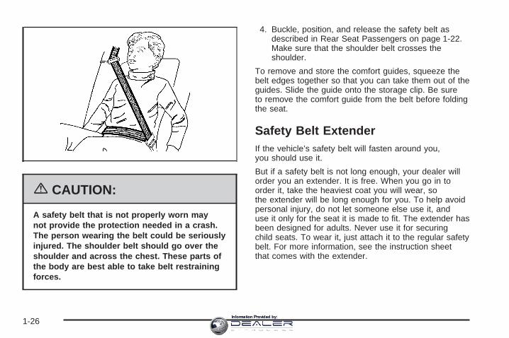
{CAUTION:
A safety belt that is not properly worn maynot provide the protection needed in a crash.The person wearing the belt could be seriouslyinjured. The shoulder belt should go over theshoulder and across the chest. These parts ofthe body are best able to take belt restrainingforces.
4. Buckle, position, and release the safety belt asdescribed in Rear Seat Passengers on page 1-22.Make sure that the shoulder belt crosses theshoulder.
To remove and store the comfort guides, squeeze thebelt edges together so that you can take them out of theguides. Slide the guide onto the storage clip. Be sureto remove the comfort guide from the belt before foldingthe seat.
Safety Belt ExtenderIf the vehicle’s safety belt will fasten around you,you should use it.
But if a safety belt is not long enough, your dealer willorder you an extender. It is free. When you go in toorder it, take the heaviest coat you will wear, sothe extender will be long enough for you. To help avoidpersonal injury, do not let someone else use it, anduse it only for the seat it is made to fit. The extender hasbeen designed for adults. Never use it for securingchild seats. To wear it, just attach it to the regular safetybelt. For more information, see the instruction sheetthat comes with the extender.
1-26Information Provided by:

Child Restraints
Older Children
Older children who have outgrown booster seats shouldwear the vehicle’s safety belts.
Q: What is the proper way to wear safety belts?
A: An older child should wear a lap-shoulder belt andget the additional restraint a shoulder belt canprovide. The shoulder belt should not cross the faceor neck. The lap belt should fit snugly below thehips, just touching the top of the thighs. It shouldnever be worn over the abdomen, which couldcause severe or even fatal internal injuries ina crash.
Accident statistics show that children are safer if theyare restrained in the rear seat.
In a crash, children who are not buckled up can strikeother people who are buckled up, or can be thrownout of the vehicle. Older children need to use safetybelts properly.
1-27Information Provided by:

{CAUTION:
Never do this.
Here two children are wearing the same belt.The belt can not properly spread the impactforces. In a crash, the two children can becrushed together and seriously injured. A beltmust be used by only one person at a time.
Q: What if a child is wearing a lap-shoulder belt,but the child is so small that the shoulder beltis very close to the child’s face or neck?
A: If the child is sitting in a seat next to a window,move the child toward the center of the vehicle.If the child is sitting in the center rear seatpassenger position, move the child toward thesafety belt buckle. Also see Rear Safety BeltComfort Guides on page 1-25. In either case, besure that the shoulder belt still is on the child’sshoulder, so that in a crash the child’s upper bodywould have the restraint that belts provide.
1-28Information Provided by:

{CAUTION:
Never do this.
Here a child is sitting in a seat that has alap-shoulder belt, but the shoulder part isbehind the child. If the child wears the belt inthis way, in a crash the child might slide underthe belt. The belt’s force would then be appliedright on the child’s abdomen. That could causeserious or fatal injuries.
The lap portion of the belt should be worn low and snugon the hips, just touching the child’s thighs. This appliesbelt force to the child’s pelvic bones in a crash.
1-29Information Provided by:

Infants and Young ChildrenEveryone in a vehicle needs protection! This includesinfants and all other children. Neither the distancetraveled nor the age and size of the traveler changesthe need, for everyone, to use safety restraints. In fact,the law in every state in the United States and inevery Canadian province says children up to some agemust be restrained while in a vehicle.
Every time infants and young children ride in vehicles,they should have the protection provided by appropriaterestraints. Young children should not use the vehicle’sadult safety belts alone, unless there is no other choice.Instead, they need to use a child restraint.
{CAUTION:
People should never hold a baby in their armswhile riding in a vehicle. A baby does notweigh much — until a crash. During a crash ababy will become so heavy it is not possible tohold it. For example, in a crash at only 25 mph(40 km/h), a 12 lb (5.5 kg) baby will suddenlybecome a 240 lb (110 kg) force on a person’sarms. A baby should be secured in anappropriate restraint.
1-30Information Provided by:

{CAUTION:
Children who are up against, or very close to,any airbag when it inflates can be seriouslyinjured or killed. Airbags plus lap-shoulderbelts offer protection for adults and olderchildren, but not for young children andinfants. Neither the vehicle’s safety belt systemnor its airbag system is designed for them.Young children and infants need the protectionthat a child restraint system can provide.
1-31Information Provided by:

Q: What are the different types of add-on childrestraints?
A: Add-on child restraints, which are purchased by thevehicle’s owner, are available in four basic types.Selection of a particular restraint should takeinto consideration not only the child’s weight, heightand age but also whether or not the restraint willbe compatible with the motor vehicle in which it willbe used.
For most basic types of child restraints, there aremany different models available. When purchasing achild restraint, be sure it is designed to be usedin a motor vehicle. If it is, the restraint will have alabel saying that it meets federal motor vehiclesafety standards.
The restraint manufacturer’s instructions that comewith the restraint, state the weight and heightlimitations for a particular child restraint. In addition,there are many kinds of restraints available forchildren with special needs.
{CAUTION:
Newborn infants need complete support,including support for the head and neck.This is necessary because a newborn infant’sneck is weak and its head weighs so muchcompared with the rest of its body. In a crash,an infant in a rear-facing seat settles intothe restraint, so the crash forces can bedistributed across the strongest part of aninfant’s body, the back and shoulders.Infants always should be secured inappropriate infant restraints.
1-32Information Provided by:

{CAUTION:
The body structure of a young child is quiteunlike that of an adult or older child, for whomthe safety belts are designed. A young child’ship bones are still so small that the vehicle’sregular safety belt may not remain low on thehip bones, as it should. Instead, it may settleup around the child’s abdomen. In a crash,the belt would apply force on a body areathat is unprotected by any bony structure.This alone could cause serious or fatalinjuries. Young children always should besecured in appropriate child restraints.
Child Restraint Systems
An infant car bed (A), a special bed made for use in amotor vehicle, is an infant restraint system designedto restrain or position a child on a continuous flatsurface. Make sure that the infant’s head rests towardthe center of the vehicle.
1-33Information Provided by:

A rear-facing infant seat (B) provides restraint withthe seating surface against the back of the infant.The harness system holds the infant in place and,in a crash, acts to keep the infant positioned inthe restraint.
A forward-facing child seat (C-E) provides restraint forthe child’s body with the harness and also sometimeswith surfaces such as T-shaped or shelf-like shields.
1-34Information Provided by:
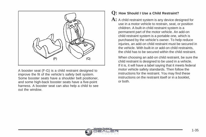
A booster seat (F-G) is a child restraint designed toimprove the fit of the vehicle’s safety belt system.Some booster seats have a shoulder belt positioner,and some high-back booster seats have a five-pointharness. A booster seat can also help a child to seeout the window.
Q: How Should I Use a Child Restraint?
A: A child restraint system is any device designed foruse in a motor vehicle to restrain, seat, or positionchildren. A built-in child restraint system is apermanent part of the motor vehicle. An add-onchild restraint system is a portable one, which ispurchased by the vehicle’s owner. To help reduceinjuries, an add-on child restraint must be secured inthe vehicle. With built-in or add-on child restraints,the child has to be secured within the child restraint.
When choosing an add-on child restraint, be sure thechild restraint is designed to be used in a vehicle.If it is, it will have a label saying that it meets federalmotor vehicle safety standards. Then follow theinstructions for the restraint. You may find theseinstructions on the restraint itself or in a booklet,or both.
1-35Information Provided by:
Securing an Add-on Child Restraint inthe Vehicle
{CAUTION:
A child can be seriously injured or killed in acrash if the child restraint is not properlysecured in the vehicle. Make sure the childrestraint is properly installed in the vehicleusing the vehicle’s safety belt or LATCHsystem, following the instructions that camewith that restraint, and also the instructions inthis manual.
To help reduce the chance of injury, the child restraintmust be secured in the vehicle. Child restraint systemsmust be secured in vehicle seats by lap belts or thelap belt portion of a lap-shoulder belt, or by the LATCHsystem. See Lower Anchors and Tethers for Children(LATCH) on page 1-39 for more information. A child canbe endangered in a crash if the child restraint is notproperly secured in the vehicle.
When securing an add-on child restraint, refer to theinstructions that come with the restraint which may be onthe restraint itself or in a booklet, or both, and to thismanual. The child restraint instructions are important,so if they are not available, obtain a replacementcopy from the manufacturer.
Keep in mind that an unsecured child restraint canmove around in a collision or sudden stop and injurepeople in the vehicle. Be sure to properly secureany child restraint in your vehicle — even when nochild is in it.
1-36Information Provided by:
Securing the Child Within theChild RestraintThere are several systems for securing the child withinthe child restraint. One system, the three-pointharness, has straps that come down over each of theinfant’s shoulders and buckle together at the crotch.The five-point harness system has two shoulder straps,two hip straps, and a crotch strap. A shield may takethe place of hip straps. A T-shaped shield has shoulderstraps that are attached to a flat pad which rests lowagainst the child’s body. A shelf- or armrest-type shieldhas straps that are attached to a wide, shelf-likeshield that swings up or to the side.
{CAUTION:
A child can be seriously injured or killed in acrash if the child is not properly secured in thechild restraint. Make sure the child is properlysecured, following the instructions that camewith that restraint.
Because there are different systems, it is important torefer to the instructions that come with the restraint.A child can be endangered in a crash if the child is notproperly secured in the child restraint.
1-37Information Provided by:
Where to Put the RestraintAccident statistics show that children are safer if theyare restrained in the rear rather than the front seat.We recommend that child restraints be secured in a rearseat, including an infant riding in a rear-facing infantseat, a child riding in a forward-facing child seat and anolder child riding in a booster seat.
Your vehicle has a rear seat that will accommodate arear-facing child restraint. A label on your sun visor says,“Never put a rear-facing child seat in the front.” This isbecause the risk to the rear-facing child is so great,if the airbag deploys.
{CAUTION:
A child in a rear-facing child restraint can beseriously injured or killed if the right frontpassenger’s airbag inflates. This is becausethe back of the rear-facing child restraintwould be very close to the inflating airbag.
Even though the passenger sensing system isdesigned to turn off the passenger’s frontalairbag if the system detects a rear-facing child
CAUTION: (Continued)
CAUTION: (Continued)
restraint, no system is fail-safe, and no onecan guarantee that an airbag will not deployunder some unusual circumstance, eventhough it is turned off. We recommend thatrear-facing child restraints be secured in therear seat, even if the airbag is off.
If you need to secure a forward-facing childrestraint in the right front seat, always movethe front passenger seat as far back as it willgo. It is better to secure the child restraint in arear seat.
Wherever you install a child restraint, be sure to securethe child restraint properly.
Keep in mind that an unsecured child restraint canmove around in a collision or sudden stop and injurepeople in the vehicle. Be sure to properly secureany child restraint in your vehicle — even when nochild is in it.
1-38Information Provided by:

Lower Anchors and Tethers forChildren (LATCH)Your vehicle has the LATCH system. The LATCHsystem holds a child restraint during driving or in acrash. This system is designed to make installationof a child restraint easier. The LATCH system usesanchors in the vehicle and attachments on thechild restraint that are made for use with theLATCH system.
Make sure that a LATCH-compatible child restraint isproperly installed using the anchors, or use the vehicle’ssafety belts to secure the restraint, following theinstructions that came with that restraint, and also theinstructions in this manual. When installing a childrestraint with a top tether, you must also use either thelower anchors or the safety belts to properly securethe child restraint. A child restraint must never beinstalled using only the top tether and anchor.
In order to use the LATCH system in your vehicle,you need a child restraint equipped with LATCHattachments. The child restraint manufacturer willprovide you with instructions on how to use the childrestraint and its attachments. The following explains howto attach a child restraint with these attachments inyour vehicle.
Your vehicle has lower anchors and top tether anchors.Your child restraint may have lower attachments anda top tether.
Not all vehicle seating positions or child restraints havelower anchors and attachments or top tether anchorsand attachments.
1-39Information Provided by:
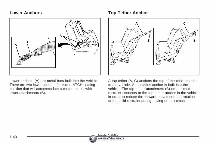
Lower Anchors
Lower anchors (A) are metal bars built into the vehicle.There are two lower anchors for each LATCH seatingposition that will accommodate a child restraint withlower attachments (B).
Top Tether Anchor
A top tether (A, C) anchors the top of the child restraintto the vehicle. A top tether anchor is built into thevehicle. The top tether attachment (B) on the childrestraint connects to the top tether anchor in the vehiclein order to reduce the forward movement and rotationof the child restraint during driving or in a crash.
1-40Information Provided by:

Your child restraint may have a single tether (A) or adual tether (C). Either will have a single attachment (B)to secure the top tether to the anchor.
Some top tether-equipped child restraints are designedfor use with or without the top tether being attached.Others require the top tether always to be attached.In Canada, the law requires that forward-facingchild restraints have a top tether, and that the tether beattached. In the United States, some child restraintsalso have a top tether. Be sure to read and follow theinstructions for your child restraint.
If the child restraint does not have a top tether, one canbe obtained, in kit form, for many child restraints. Askthe child restraint manufacturer whether or not a kitis available.
Lower Anchor and Top Tether AnchorLocations
i (Top Tether Anchor):Seating positions withtop tether anchors.
j (Lower Anchor):Seating positions withtwo lower anchors.
The right side rear passenger and center seatingpositions have exposed metal anchors located in thecrease between the seatback and the seat cushion.
Rear Seat
1-41Information Provided by:

The top tether anchors are located on the back of therear seat frame above the floor for each rear seatingposition. Fold down the rear seatback(s) to accessthe anchors. See Rear Seat Operation on page 1-7.Be sure to use an anchor located on the same side ofthe vehicle as the seating position where the childrestraint will be placed.
Do not secure a child restraint in the right frontpassenger’s position if a national or local law requiresthat the top tether be attached, or if the instructions thatcome with the child restraint say that the top tethermust be attached. There is no place to attach the toptether in this position.
Accident statistics show that children are safer if theyare restrained in the rear rather than the front seat.See Where to Put the Restraint on page 1-38 foradditional information.
1-42Information Provided by:

Securing a Child Restraint Designed forthe LATCH System
{CAUTION:
If a LATCH-type child restraint is not attached toanchors, the restraint will not be able to protectthe child correctly. In a crash, the child could beseriously injured or killed. Make sure that aLATCH-type child restraint is properly installedusing the anchors, or use the vehicle’s safetybelts to secure the restraint, following theinstructions that came with that restraint, andalso the instructions in this manual.
{CAUTION:
Each top tether anchor and lower anchor inthe vehicle is designed to hold only one childrestraint. Attaching more than one childrestraint to a single anchor could cause theanchor or attachment to come loose or evenbreak during a crash. A child or others could beinjured if this happens. To help prevent injury topeople and damage to your vehicle, attach onlyone child restraint per anchor.
1. If the child restraint manufacturer recommends thatthe top tether be attached, attach the top tether tothe top tether anchor, if equipped. Refer to thechild restraint instructions and the following steps:
1.1. To access the top tether anchors, raisethe seat cushion by pulling up on the straploop at the rear of the seat cushion andfold the seat cushion forward. Then fold theseatback forward until it is flat. See RearSeat Operation on page 1-7 for additionalinformation.
1.2. Place the child restraint in the vehicle, nearthe seating position that you are using.
1-43Information Provided by:

1.3. Route the top tether according to your childrestraint instructions and the followinginstructions:
If the position you areusing does not have ahead restraint and you areusing a single tether,route the tether over theseatback.
If the position you areusing does not have ahead restraint and youare using a dual tether,route the tether overthe seatback.
If the position you areusing has an adjustablehead restraint and you areusing a dual tether, routethe tether around thehead restraint.
If the position you are usinghas an adjustable headrestraint and you are usinga single tether, raise thehead restraint and route thetether under the headrestraint and in between thehead restraint posts.
1.4. Attach the top tether attachment to the toptether anchor.
1-44Information Provided by:
{CAUTION:
If the seatback is not locked, it could moveforward in a sudden stop or crash. That couldcause injury to the person sitting there. Alwayspush and pull on the seatback to be sure it islocked.
1.5. Lift the seatback up and push it rearward.Then lower the seat cushion until theseatback and the seat cushion lock intoposition.
2. Attach the lower attachments to the lower anchors.If the child restraint does not have lowerattachments or the desired seating position doesnot have lower anchors, secure the child restraintwith the top tether and the safety belts. Refer toyour child restraint manufacturer instructionsand the instructions in this manual.
2.1. Find the lower anchors for the desiredseating position.
2.2. Put the child restraint on the seat.2.3. Attach and tighten the lower attachments
on the child restraint to the lower anchors.
3. Tighten the top tether.
4. Push and pull the child restraint in differentdirections to be sure it is secure.
1-45Information Provided by:
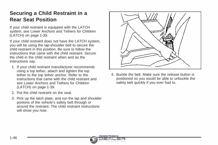
Securing a Child Restraint in aRear Seat PositionIf your child restraint is equipped with the LATCHsystem, see Lower Anchors and Tethers for Children(LATCH) on page 1-39.
If your child restraint does not have the LATCH system,you will be using the lap-shoulder belt to secure thechild restraint in this position. Be sure to follow theinstructions that came with the child restraint. Securethe child in the child restraint when and as theinstructions say.
1. If your child restraint manufacturer recommendsusing a top tether, attach and tighten the toptether to the top tether anchor. Refer to theinstructions that came with the child restraint andsee Lower Anchors and Tethers for Children(LATCH) on page 1-39.
2. Put the child restraint on the seat.
3. Pick up the latch plate, and run the lap and shoulderportions of the vehicle’s safety belt through oraround the restraint. The child restraint instructionswill show you how.
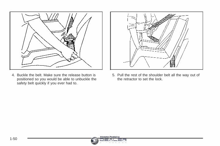
4. Buckle the belt. Make sure the release button ispositioned so you would be able to unbuckle thesafety belt quickly if you ever had to.
1-46Information Provided by:

5. Pull the rest of the shoulder belt all the way out ofthe retractor to set the lock.
6. To tighten the belt, push down on the child restraint,pull the shoulder portion of the belt to tighten thelap portion of the belt and feed the shoulderbelt back into the retractor. If you are using aforward-facing child restraint, you may find ithelpful to use your knee to push down on thechild restraint as you tighten the belt.
7. Push and pull the child restraint in differentdirections to be sure it is secure.
To remove the child restraint, unbuckle the vehicle’ssafety belt and let it go back all the way. The safety beltwill move freely again and be ready to work for anadult or larger child passenger. If the top tetheris attached to the top tether anchor, disconnect it.
1-47Information Provided by:

Securing a Child Restraint in theRight Front Seat PositionYour vehicle has a right front passenger’s airbag. A rearseat is a safer place to secure a forward-facing childrestraint. See Where to Put the Restraint on page 1-38.
In addition, your vehicle may have the passengersensing system. The passenger sensing system isdesigned to turn off the right front passenger’s frontalairbag when an infant in a rear-facing infant seator a small child in a forward-facing child restraint orbooster seat is detected. See Passenger SensingSystem on page 1-60 and Passenger Airbag StatusIndicator on page 3-32 for more information onthis including important safety information.
A label on your sun visor says, “Never put a rear-facingchild seat in the front.” This is because the risk to therear-facing child is so great, if the airbag deploys.
{CAUTION:
A child in a rear-facing child restraint can beseriously injured or killed if the right frontpassenger’s airbag inflates. This is becausethe back of the rear-facing child restraintwould be very close to the inflating airbag.
Even though the passenger sensing system isdesigned to turn off the passenger’s frontalairbag if the system detects a rear-facing childrestraint, no system is fail-safe, and no onecan guarantee that an airbag will not deployunder some unusual circumstance, eventhough it is turned off. We recommend thatrear-facing child restraints be secured in therear seat, even if the airbag is off.
1-48Information Provided by:

If you need to secure a forward-facing child restraint inthe right front seat position, move the seat as farback as it will go before securing the forward-facingchild restraint. See Power Seats on page 1-2.
If your child restraint is equipped with the LATCHsystem, see Lower Anchors and Tethers for Children(LATCH) on page 1-39.
There is no top tether anchor in the right frontpassenger’s position. Do not secure a child seat in thisposition if a national or local law requires that thetop tether be anchored, or if the instructions that comewith the child restraint say that the top tether mustbe anchored. See Lower Anchors and Tethers forChildren (LATCH) on page 1-39 if the child restraint hasa top tether.
You will be using the lap-shoulder belt to secure thechild restraint in this position. Be sure to follow theinstructions that came with the child restraint.Secure the child in the child restraint when and as theinstructions say.
1. Your vehicle has a right front passenger’s frontalairbag. See Passenger Sensing System onpage 1-60. General Motors recommends thatrear-facing child restraints be secured in a rear seat,even if the airbag is off. If your child restraint isforward-facing, move the seat as far back as it willgo before securing the child restraint in thisseat. See Power Seats on page 1-2.When the passenger sensing system has turned offthe right front passenger’s frontal airbag, the offindicator in the passenger airbag status indicatorshould light and stay lit when you turn the ignition toRUN or START. See Passenger Airbag StatusIndicator on page 3-32.
2. Put the child restraint on the seat.
3. Pick up the latch plate, and run the lap and shoulderportions of the vehicle’s safety belt through oraround the restraint. The child restraint instructionswill show you how.
1-49Information Provided by:
4. Buckle the belt. Make sure the release button ispositioned so you would be able to unbuckle thesafety belt quickly if you ever had to.
5. Pull the rest of the shoulder belt all the way out ofthe retractor to set the lock.
1-50Information Provided by:

6. To tighten the belt, push down on the child restraint,pull the shoulder portion of the belt to tighten thelap portion of the belt and feed the shoulderbelt back into the retractor. If you are using aforward-facing child restraint, you may find it helpfulto use your knee to push down on the childrestraint as you tighten the belt. You should not beable to pull more of the belt from the retractoronce the lock has been set.
7. Push and pull the child restraint in differentdirections to be sure it is secure.
8. If your vehicle has the passenger sensing systemand the airbag is off, the off indicator will be lit andstay lit in the inside rearview mirror when thekey is turned to RUN or START.
If a child restraint has been installed and the onindicator is lit, turn the vehicle off. Remove the childrestraint from the vehicle and reinstall the child restraint.
If after reinstalling the child restraint and restartingthe vehicle, the on indicator is still lit, check to makesure that the vehicle’s seatback is not pressing the childrestraint into the seat cushion. If this happens, slightlyrecline the vehicle’s seatback and adjust the seatcushion if possible. Also make sure the child restraint isnot trapped under the vehicle head restraint. If thishappens, adjust the head restraint.
If the on indicator is still lit, secure the child in the childrestraint in a rear seat position in the vehicle andcheck with your dealer.
To remove the child restraint, just unbuckle the vehicle’ssafety belt and let it go back all the way. The safetybelt will move freely again and be ready to work for anadult or larger child passenger.
1-51Information Provided by:
Airbag SystemYour vehicle has a frontal airbag for the driver, a frontalairbag for the right front passenger, a side impactairbag for the driver, and a side impact airbag for theright front passenger.
Frontal airbags are designed to help reduce the risk ofinjury from the force of an inflating frontal airbag.But these airbags must inflate very quickly to do theirjob and comply with federal regulations.
Here are the most important things to know about theairbag system:
{CAUTION:
You can be severely injured or killed in a crashif you are not wearing your safety belt — evenif you have airbags. Wearing your safety beltduring a crash helps reduce your chance ofhitting things inside the vehicle or beingejected from it. Airbags are “supplementalrestraints” to the safety belts. Airbags aredesigned to work with safety belts but do notreplace them.
CAUTION: (Continued)
CAUTION: (Continued)
Frontal airbags for the driver and right frontpassenger are designed to deploy in moderateto severe frontal and near frontal crashes.They are not designed to inflate in rollover,rear crashes, or in many side crashes. And, forsome unrestrained occupants, frontal airbagsmay provide less protection in frontal crashesthan more forceful airbags have provided inthe past.
Side impact airbags are designed to inflate inmoderate to severe crashes where somethinghits the side of your vehicle. They are notdesigned to inflate in frontal, in rollover or inrear crashes.
Everyone in your vehicle should wear a safetybelt properly — whether or not there is anairbag for that person.
1-52Information Provided by:
{CAUTION:
Both frontal and side impact airbags inflatewith great force, faster than the blink of aneye. If you are too close to an inflating airbag,as you would be if you were leaning forward,it could seriously injure you. Safety belts helpkeep you in position for airbag inflation beforeand during a crash. Always wear your safetybelt, even with frontal airbags. The drivershould sit as far back as possible whilestill maintaining control of the vehicle.Front occupants should not lean on orsleep against the door.
{CAUTION:
Anyone who is up against, or very close to,any airbag when it inflates can be seriouslyinjured or killed. Airbags plus lap-shoulderbelts offer the best protection for adults, butnot for young children and infants. Neither thevehicle’s safety belt system nor its airbagsystem is designed for them. Young childrenand infants need the protection that a childrestraint system can provide. Always securechildren properly in your vehicle. To read how,see Older Children on page 1-27 or Infants andYoung Children on page 1-30.
1-53Information Provided by:

There is an airbagreadiness light on theinstrument panel cluster,which shows the airbagsymbol.
The system checks the airbag electrical system formalfunctions. The light tells you if there is an electricalproblem. See Airbag Readiness Light on page 3-31for more information.
Where Are the Airbags?
The driver’s frontal airbag is in the middle of thesteering wheel.
1-54Information Provided by:

The right front passenger’s frontal airbag is in theinstrument panel on the passenger’s side.
The driver’s side impact airbag is in the side of thedriver’s seatback closest to the door.
1-55Information Provided by:
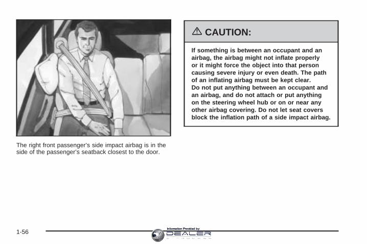
The right front passenger’s side impact airbag is in theside of the passenger’s seatback closest to the door.
{CAUTION:
If something is between an occupant and anairbag, the airbag might not inflate properlyor it might force the object into that personcausing severe injury or even death. The pathof an inflating airbag must be kept clear.Do not put anything between an occupant andan airbag, and do not attach or put anythingon the steering wheel hub or on or near anyother airbag covering. Do not let seat coversblock the inflation path of a side impact airbag.
1-56Information Provided by:

When Should an Airbag Inflate?The driver’s and right front passenger’s frontal airbagsare designed to inflate in moderate to severe frontalor near-frontal crashes. But they are designed to inflateonly if the impact exceeds a predetermined deploymentthreshold. Deployment thresholds take into accounta variety of desired deployment and non-deploymentevents and are used to predict how severe a crashis likely to be in time for the airbags to inflate and helprestrain the occupants. Whether your frontal airbagswill or should deploy is not based on how fast yourvehicle is traveling. It depends largely on what you hit,the direction of the impact and how quickly yourvehicle slows down.
In addition, your vehicle has “dual stage” frontal airbags,which adjust the restraint according to crash severity.Your vehicle is equipped with electronic frontal sensorswhich help the sensing system distinguish betweena moderate and a more severe frontal impact. Formoderate frontal impacts, these airbags inflate at a levelless than full deployment. For more severe frontalimpacts, full deployment occurs. If the front of yourvehicle goes straight into a wall that does not move ordeform, the threshold level for the reduced deployment isabout 10 to 16 mph (16 to 25 km/h), and the thresholdlevel for a full deployment is about 20 to 30 mph(32 to 48 km/h). (The threshold level can vary, however,with specific vehicle design, so that it can be somewhatabove or below this range.)
Frontal airbags may inflate at different crash speeds.For example:• If the vehicle hits a stationary object, the airbags
could inflate at a different crash speed than if thevehicle hits a moving object.
• If the vehicle hits an object that deforms, theairbags could inflate at a different crash speed thanif the vehicle hits an object that does not deform.
• If the vehicle hits a narrow object (like a pole) theairbags could inflate at a different crash speedthan if the vehicle hits a wide object (like a wall).
• If the vehicle goes into an object at an angle theairbags could inflate at a different crash speedthan if the vehicle goes straight into the object.
The frontal airbags (driver and right front passenger)are not intended to inflate during vehicle rollovers,rear impacts, or in many side impacts.
Side impact airbags are intended to inflate in moderateto severe side crashes. A side impact airbag willinflate if the crash severity is above the system’sdesigned “threshold level.” The threshold level can varywith specific vehicle design. Side impact airbags arenot intended to inflate in frontal or near-frontal impacts,rollovers or rear impacts, because inflation wouldnot likely help the occupant. A side impact airbag isintended to deploy on the side of the vehicle thatis struck.
1-57Information Provided by:

Vehicle’s with dual stage airbags are also equipped withspecial sensors which enable the sensing system tomonitor the position of both the driver and passengerfront seats. The seat position sensor providesinformation which is used to determine if the airbagsshould deploy at a reduced level or at full deployment.
In any particular crash, no one can say whether an airbagshould have inflated simply because of the damage to avehicle or because of what the repair costs were.For frontal airbags, inflation is determined by what thevehicle hits, the angle of the impact, and how quickly thevehicle slows down. For side impact airbags, inflation isdetermined by the location and severity of the impact.
The airbag system is designed to work properly under awide range of conditions, including off-road usage.Observe safe driving speeds, especially on roughterrain. As always, wear your safety belt. See Off-RoadDriving on page 4-17 for tips on off-road driving.
What Makes an Airbag Inflate?In an impact of sufficient severity, the airbag sensingsystem detects that the vehicle is in a crash.The sensing system triggers a release of gas from theinflator, which inflates the airbag. The inflator, the airbagand related hardware are all part of the airbag modulesinside the steering wheel, the instrument panel, andthe side of the front seatbacks closest to the door.
How Does an Airbag Restrain?In moderate to severe frontal or near frontal collisions,even belted occupants can contact the steering wheelor the instrument panel. In moderate to severe sidecollisions, even belted occupants can contact the insideof the vehicle. The airbag supplements the protectionprovided by safety belts. Airbags distribute the force ofthe impact more evenly over the occupant’s upper body,stopping the occupant more gradually. But the frontalairbags would not help you in many types of collisions,including rollovers, rear impacts, and many side impacts,primarily because an occupant’s motion is not towardthe airbag. Side impact airbags would not help youin many types of collisions, including many frontal ornear frontal collisions, and rear impacts, primarilybecause an occupant’s motion is not toward thoseairbags. Airbags should never be regarded as anythingmore than a supplement to safety belts, and thenonly in moderate to severe frontal or near-frontalcollisions for the frontal airbags, and only in moderateto severe side collisions for vehicles with a sideimpact airbag.
1-58Information Provided by:
What Will You See After anAirbag Inflates?After the airbag inflates, it quickly deflates, so quicklythat some people may not even realize the airbaginflated. Some components of the airbag module maybe hot for a short time. These components includethe steering wheel hub for the driver’s frontal airbag andthe instrument panel for the right front passenger’sfrontal airbag. For side impact airbags, the side of theseatback closest to the driver’s and/or right frontpassenger’s door may be hot. The parts of the bag thatcome into contact with you may be warm, but not toohot to touch. There will be some smoke and dust comingfrom the vents in the deflated airbags. Airbag inflationdoes not prevent the driver from seeing or being able tosteer the vehicle, nor does it stop people from leavingthe vehicle.
{CAUTION:
When an airbag inflates, there is dust in theair. This dust could cause breathing problemsfor people with a history of asthma or otherbreathing trouble. To avoid this, everyone inthe vehicle should get out as soon as it is safeto do so. If you have breathing problems butcannot get out of the vehicle after an airbaginflates, then get fresh air by opening awindow or a door. If you experience breathingproblems following an airbag deployment,you should seek medical attention.
1-59Information Provided by:
In many crashes severe enough to inflate an airbag,windshields are broken by vehicle deformation.Additional windshield breakage may also occur fromthe right front passenger airbag.
• Airbags are designed to inflate only once. After anairbag inflates, you will need some new parts foryour airbag system. If you do not get them,the airbag system will not be there to help protectyou in another crash. A new system will includeairbag modules and possibly other parts. Theservice manual for your vehicle covers the need toreplace other parts.
• Your vehicle is equipped with a crash sensing anddiagnostic module which records information aftera crash. See Vehicle Data Collection and EventData Recorders on page 7-9.
• Let only qualified technicians work on your airbagsystem. Improper service can mean that anairbag system will not work properly. See yourdealer for service.
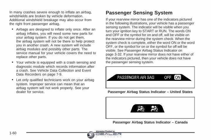
Passenger Sensing SystemIf your rearview mirror has one of the indicators picturedin the following illustrations, your vehicle has a passengersensing system. The indicator will be visible when youturn your ignition key to START or RUN. The words ONand OFF or the symbol for on and off, will be visible onthe rearview mirror during the system check. When thesystem check is complete, either the word ON or the wordOFF, or the symbol for on or the symbol for off will bevisible. See Passenger Airbag Status Indicator onpage 3-32. If your rearview mirror does not have either ofthe indicators pictured, then your vehicle does not havethe passenger sensing system.
Passenger Airbag Status Indicator – United States
Passenger Airbag Status Indicator – Canada
1-60Information Provided by:
The passenger sensing system will turn off the rightfront passenger’s frontal airbag under certain conditions.The driver’s airbag and the side airbags are not partof the passenger sensing system.
The passenger sensing system works with sensors thatare part of the right front passenger’s seat and safetybelt. The sensors are designed to detect the presence ofa properly-seated occupant and determine if thepassenger’s frontal airbag should be enabled(may inflate) or not.
Accident statistics show that children are safer if theyare restrained in the rear rather than the front seat.General Motors recommends that child restraintsbe secured in a rear seat, including an infant riding in arear-facing infant seat, a child riding in a forward-facingchild seat and an older child riding in a booster seat.
Your vehicle has a rear seat that will accommodatea rear-facing child restraint. A label on your sun visorsays, “Never put a rear-facing child seat in thefront.” This is because the risk to the rear-facing child isso great, if the airbag deploys.
{CAUTION:
A child in a rear-facing child restraint can beseriously injured or killed if the right frontpassenger’s airbag inflates. This is becausethe back of the rear-facing child restraintwould be very close to the inflating airbag.
Even though the passenger sensing system isdesigned to turn off the passenger’s frontalairbag if the system detects a rear-facing childrestraint, no system is fail-safe, and no onecan guarantee that an airbag will not deployunder some unusual circumstance, eventhough it is turned off. We recommend thatrear-facing child restraints be secured in therear seat, even if the airbag is off.
If you need to secure a forward-facing childrestraint in the right front seat, always movethe front passenger seat as far back as it willgo. It is better to secure the child restraint in arear seat.
1-61Information Provided by:

The passenger sensing system is designed to turn offthe right front passenger’s frontal airbag if:
• the right front passenger seat is unoccupied
• the system determines that an infant is present in arear-facing infant seat
• the system determines that a small child is presentin a forward-facing child restraint
• the system determines that a small child is presentin a booster seat
• a right front passenger takes his/her weight off ofthe seat for a period of time
• the right front passenger seat is occupied by asmaller person, such as a child who has outgrownchild restraints
• or if there is a critical problem with the airbagsystem or the passenger sensing system.
When the passenger sensing system has turned off thepassenger’s frontal airbag, the off indicator will lightand stay lit to remind you that the airbag is off.
If a child restraint has been installed and the on indicatoris lit, turn the vehicle off. Remove the child restraintfrom the vehicle and reinstall the child restraint followingthe child restraint manufacturer’s directions and referto Securing a Child Restraint in the Right FrontSeat Position on page 1-48.
If after reinstalling the child restraint and restarting thevehicle, the on indicator is still lit, check to makesure that the vehicle’s seatback is not pressing the childrestraint into the seat cushion. If this happens, slightlyrecline the vehicle’s seatback and adjust the seatcushion if possible. Also make sure the child restraintis not trapped under the vehicle head restraint.If this happens, adjust the head restraint.
If the on indicator is still lit, secure the child in the childrestraint in a rear seat position in the vehicle andcheck with your dealer.
The passenger sensing system is designed to enable(may inflate) the right front passenger’s frontalairbag anytime the system senses that a person of adultsize is sitting properly in the right front passenger’sseat. When the passenger sensing system has allowedthe airbag to be enabled, the on indicator will lightand stay lit to remind you that the airbag is active.
For some children who have outgrown child restraintsand for very small adults, the passenger sensing systemmay or may not turn off the right front passenger’sfrontal airbag, depending upon the person’s seatingposture and body build. Everyone in your vehicle whohas outgrown child restraints should wear a safetybelt properly — whether or not there is an airbag forthat person.
1-62Information Provided by:
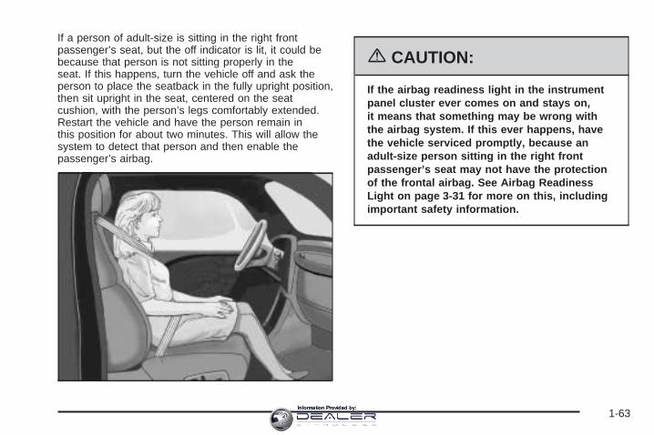
If a person of adult-size is sitting in the right frontpassenger’s seat, but the off indicator is lit, it could bebecause that person is not sitting properly in theseat. If this happens, turn the vehicle off and ask theperson to place the seatback in the fully upright position,then sit upright in the seat, centered on the seatcushion, with the person’s legs comfortably extended.Restart the vehicle and have the person remain inthis position for about two minutes. This will allow thesystem to detect that person and then enable thepassenger’s airbag.
{CAUTION:
If the airbag readiness light in the instrumentpanel cluster ever comes on and stays on,it means that something may be wrong withthe airbag system. If this ever happens, havethe vehicle serviced promptly, because anadult-size person sitting in the right frontpassenger’s seat may not have the protectionof the frontal airbag. See Airbag ReadinessLight on page 3-31 for more on this, includingimportant safety information.
1-63Information Provided by:

Aftermarket equipment, such as seat covers, can affecthow well the passenger sensing system operates.You may want to consider not using seat covers or otheraftermarket equipment if your vehicle has the passengersensing system. See Adding Equipment to YourAirbag-Equipped Vehicle on page 1-65 for moreinformation about modifications that can affect how thesystem operates.
{CAUTION:
Stowing of articles under the passenger’s seator between the passenger’s seat cushion andseatback may interfere with the properoperation of the passenger sensing system.
Servicing Your Airbag-EquippedVehicleAirbags affect how your vehicle should be serviced.There are airbag system parts in several places aroundyour vehicle. You do not want the system to inflate whilesomeone is working on your vehicle. Your dealer and theservice manual have information about servicing yourvehicle and the airbag system. To purchase a servicemanual, see Service Publications Ordering Informationon page 7-14.
{CAUTION:
For up to 10 seconds after the ignition key isturned off and the battery is disconnected, anairbag can still inflate during improper service.You can be injured if you are close to anairbag when it inflates. Avoid yellowconnectors. They are probably part of theairbag system. Be sure to follow properservice procedures, and make sure the personperforming work for you is qualified to do so.
The airbag system does not need regular maintenance.
1-64Information Provided by:

Adding Equipment to YourAirbag-Equipped Vehicle
Q: Is there anything I might add to the front orsides of the vehicle that could keep theairbags from working properly?
A: Yes. If you add things that change your vehicle’sframe, bumper system, front end or side sheetmetal or height, they may keep the airbag systemfrom working properly. Also, the airbag system maynot work properly if you relocate any of the airbagsensors. If you have any questions about this,you should contact Customer Assistance beforeyou modify your vehicle. The phone numbersand addresses for Customer Assistance are inStep Two of the Customer Satisfaction Procedurein this manual. See Customer SatisfactionProcedure on page 7-2.
Q: Because I have a disability, I have to get myvehicle modified. How can I find out whetherthis will affect my advanced airbag system?
A: Changing or moving any parts of the front seats,safety belts, the airbag sensing and diagnosticmodule (located under the driver’s seat), orthe inside rearview mirror can affect the operationof the advanced airbag system. If you havequestions, call Customer Assistance. The phonenumbers and addresses for Customer Assistanceare in Step Two of the Customer SatisfactionProcedure in this manual. See CustomerSatisfaction Procedure on page 7-2.
1-65Information Provided by:
Restraint System Check
Checking the Restraint SystemsNow and then, make sure the safety belt reminder lightand all your belts, buckles, latch plates, retractorsand anchorages are working properly. Look for any otherloose or damaged safety belt system parts. If you seeanything that might keep a safety belt system from doingits job, have it repaired.
Torn or frayed safety belts may not protect you in acrash. They can rip apart under impact forces. If a beltis torn or frayed, get a new one right away.
Also look for any opened or broken airbag covers, andhave them repaired or replaced. (The airbag systemdoes not need regular maintenance.)
Notice: If you damage the covering for a frontalairbag, or an airbag covering on a seatback,the airbag may not work properly. You may have toreplace the airbag module in the steering wheel,both the airbag module and the instrument panel forthe right front passenger’s frontal airbag, or boththe airbag module and seatback for seatingpositions with a side impact airbag. Do not openor break the airbag coverings.
1-66Information Provided by:

Replacing Restraint System PartsAfter a Crash
{CAUTION:
A crash can damage the restraint systems inyour vehicle. A damaged restraint systemmay not properly protect the person using it,resulting in serious injury or even death in acrash. To help make sure your restraintsystems are working properly after a crash,have them inspected and any necessaryreplacements made as soon as possible.
If you have had a crash, do you need new belts orLATCH system parts?
After a very minor collision, nothing may be necessary.But if the belts were stretched, as they would be ifworn during a more severe crash, then you neednew parts.
If the LATCH system was being used during a moresevere crash, you may need new LATCH system parts.
If belts are cut or damaged, replace them. Collisiondamage also may mean you will need to have LATCHsystem, safety belt or seat parts repaired or replaced.New parts and repairs may be necessary even if the beltor LATCH system was not being used at the time ofthe collision.
If an airbag inflates, you will need to replace airbagsystem parts. See the part on the airbag system earlierin this section.
1-67Information Provided by:

✍ NOTES
1-68Information Provided by:
Keys ...............................................................2-3Remote Keyless Entry System .........................2-4Remote Keyless Entry System Operation ...........2-5
Doors and Locks .............................................2-8Door Locks ....................................................2-8Power Door Locks ..........................................2-9Delayed Locking .............................................2-9Programmable Automatic Door Locks ..............2-10Rear Door Security Locks ..............................2-10Lockout Protection ........................................2-10Midgate® .....................................................2-11Tailgate .......................................................2-19
Windows ........................................................2-21Power Windows ............................................2-22Sun Visors ...................................................2-23
Theft-Deterrent Systems ..................................2-23Content Theft-Deterrent .................................2-23Passlock® ....................................................2-25
Starting and Operating Your Vehicle ................2-25New Vehicle Break-In ....................................2-25Ignition Positions ..........................................2-26Retained Accessory Power (RAP) ...................2-26Starting the Engine .......................................2-27
Adjustable Throttle and Brake Pedal ................2-28Engine Coolant Heater ..................................2-28Automatic Transmission Operation ...................2-30Tow/Haul Mode ............................................2-32Parking Brake ..............................................2-33Shifting Into Park (P) .....................................2-34Shifting Out of Park (P) .................................2-35Parking Over Things That Burn .......................2-36Engine Exhaust ............................................2-36Running the Engine While Parked ...................2-37
Mirrors ...........................................................2-38Automatic Dimming Rearview Mirror
with OnStar® and Compass ........................2-38Automatic Dimming Rearview Mirror
with OnStar®, Compass andTemperature Display ..................................2-39
Automatic Dimming Rearview Mirrorwith Compass ...........................................2-42
Outside Power Mirrors ...................................2-43Outside Convex Mirror ...................................2-44Outside Heated Mirrors ..................................2-45Outside Automatic Dimming Mirror with
Curb View Assist .......................................2-45
Section 2 Features and Controls
2-1Information Provided by:

OnStar ® System .............................................2-46Universal Home Remote System ......................2-48
Universal Home Remote System Operation ......2-49Storage Areas ................................................2-53
Glove Box ...................................................2-53Cupholder(s) ................................................2-53Instrument Panel Storage Area .......................2-53Center Console Storage Area .........................2-53
Luggage Carrier ...........................................2-54Rear Seat Armrest ........................................2-55Cargo Cover Panels ......................................2-55All-Weather Cargo Area .................................2-68Top-Box Storage ..........................................2-72
Sunroof .........................................................2-73Vehicle Personalization ...................................2-74
Memory Seat ...............................................2-74
Section 2 Features and Controls
2-2Information Provided by:

Keys
{CAUTION:
Leaving children in a vehicle with the ignitionkey is dangerous for many reasons. They couldoperate the power windows or other controls oreven make the vehicle move. The children orothers could be badly injured or even killed.Do not leave the keys in a vehicle with children.
2-3Information Provided by:
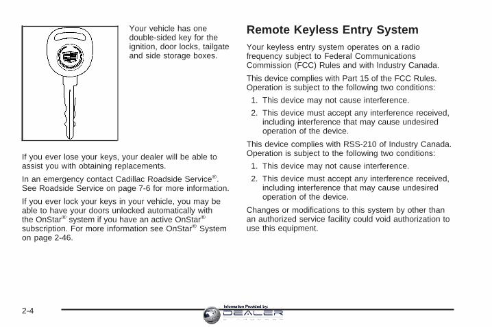
Your vehicle has onedouble-sided key for theignition, door locks, tailgateand side storage boxes.
If you ever lose your keys, your dealer will be able toassist you with obtaining replacements.
In an emergency contact Cadillac Roadside Service®.See Roadside Service on page 7-6 for more information.
If you ever lock your keys in your vehicle, you may beable to have your doors unlocked automatically withthe OnStar® system if you have an active OnStar®
subscription. For more information see OnStar® Systemon page 2-46.
Remote Keyless Entry SystemYour keyless entry system operates on a radiofrequency subject to Federal CommunicationsCommission (FCC) Rules and with Industry Canada.
This device complies with Part 15 of the FCC Rules.Operation is subject to the following two conditions:
1. This device may not cause interference.
2. This device must accept any interference received,including interference that may cause undesiredoperation of the device.
This device complies with RSS-210 of Industry Canada.Operation is subject to the following two conditions:
1. This device may not cause interference.
2. This device must accept any interference received,including interference that may cause undesiredoperation of the device.
Changes or modifications to this system by other thanan authorized service facility could void authorization touse this equipment.
2-4Information Provided by:

At times you may notice a decrease in range. This isnormal for any remote keyless entry system. If thetransmitter does not work or if you have to stand closerto your vehicle for the transmitter to work, try this:
• Check the distance. You may be too far from yourvehicle. You may need to stand closer duringrainy or snowy weather.
• Check the location. Other vehicles or objects maybe blocking the signal. Take a few steps to theleft or right, hold the transmitter higher, andtry again.
• Check to determine if battery replacement isnecessary. See “Battery Replacement” underRemote Keyless Entry System Operation onpage 2-5.
• If you are still having trouble, see your dealer or aqualified technician for service.
Remote Keyless Entry SystemOperationYou can lock and unlock your doors from about 3 feet(1 m) up to 100 feet (30 m) away using the remotekeyless entry transmitter supplied with your vehicle.
K (Unlock): Press thisbutton once to unlockthe driver’s door.The interior lamps willcome on. Pressing unlockagain within three secondswill cause the remainingdoors to unlock.
You can choose different feedback options for eachpress of the unlock button. See “Lock Feedback” and“Unlock Feedback” under DIC Vehicle Customization onpage 3-57 for more information.
2-5Information Provided by:

Q (Lock): Press this button once to lock all of thedoors. Pressing lock again within three secondsmay cause the horn to chirp for lock confirmation.You can choose different feedback options for eachpress of the lock button. See “Lock Feedback” and“Unlock Feedback” under DIC Vehicle Customization onpage 3-57 for more information.
L (Panic): Press this button to sound the horn andflash the headlamps and taillamps for up to 30 seconds.Panic can be turned off by pressing the button again,by waiting for 30 seconds, or by starting the vehicle.
Matching Transmitter(s) to Your VehicleEach remote keyless entry transmitter is coded toprevent another transmitter from unlocking your vehicle.If a transmitter is lost or stolen, a replacement canbe purchased through your dealer. Remember to bringany remaining transmitters with you when you go toyour dealer. When the dealer matches the replacementtransmitter to your vehicle, any remaining transmittersmust also be matched. Once your dealer has coded thenew transmitter, the lost transmitter will not unlockyour vehicle. Each vehicle can have a maximum offour transmitters matched to it.
Battery ReplacementUnder normal use, the battery in your remote keylessentry transmitter should last about two years.
You can tell the battery is weak if the transmitter will notwork at the normal range in any location. If you haveto get close to your vehicle before the transmitter works,it is probably time to change the battery.
Notice: When replacing the battery, use care not totouch any of the circuitry. Static from your bodytransferred to these surfaces may damage thetransmitter.
2-6Information Provided by:
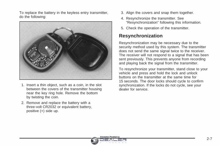
To replace the battery in the keyless entry transmitter,do the following:
1. Insert a thin object, such as a coin, in the slotbetween the covers of the transmitter housingnear the key ring hole. Remove the bottomby twisting the coin.
2. Remove and replace the battery with athree-volt CR2032 or equivalent battery,positive (+) side up.
3. Align the covers and snap them together.
4. Resynchronize the transmitter. See“Resynchronization” following this information.
5. Check the operation of the transmitter.
ResynchronizationResynchronization may be necessary due to thesecurity method used by this system. The transmitterdoes not send the same signal twice to the receiver.The receiver will not respond to a signal that has beensent previously. This prevents anyone from recordingand playing back the signal from the transmitter.
To resynchronize your transmitter, stand close to yourvehicle and press and hold the lock and unlockbuttons on the transmitter at the same time for15 seconds. The door locks should cycle to confirmsynchronization. If the locks do not cycle, see yourdealer for service.
2-7Information Provided by:
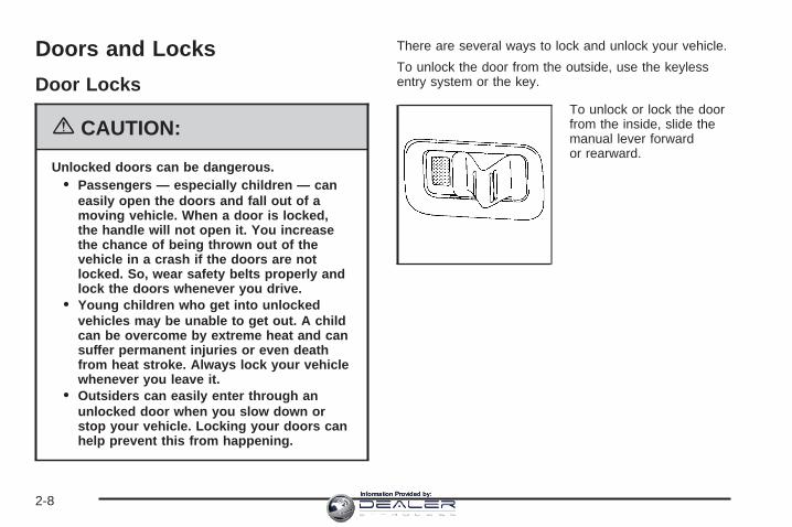
Doors and Locks
Door Locks
{CAUTION:
Unlocked doors can be dangerous.• Passengers — especially children — can
easily open the doors and fall out of amoving vehicle. When a door is locked,the handle will not open it. You increasethe chance of being thrown out of thevehicle in a crash if the doors are notlocked. So, wear safety belts properly andlock the doors whenever you drive.
• Young children who get into unlockedvehicles may be unable to get out. A childcan be overcome by extreme heat and cansuffer permanent injuries or even deathfrom heat stroke. Always lock your vehiclewhenever you leave it.
• Outsiders can easily enter through anunlocked door when you slow down orstop your vehicle. Locking your doors canhelp prevent this from happening.
There are several ways to lock and unlock your vehicle.
To unlock the door from the outside, use the keylessentry system or the key.
To unlock or lock the doorfrom the inside, slide themanual lever forwardor rearward.
2-8Information Provided by:
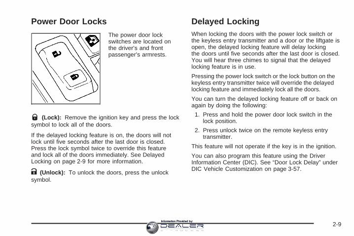
Power Door LocksThe power door lockswitches are located onthe driver’s and frontpassenger’s armrests.
Q (Lock): Remove the ignition key and press the locksymbol to lock all of the doors.
If the delayed locking feature is on, the doors will notlock until five seconds after the last door is closed.Press the lock symbol twice to override this featureand lock all of the doors immediately. See DelayedLocking on page 2-9 for more information.
K (Unlock): To unlock the doors, press the unlocksymbol.
Delayed LockingWhen locking the doors with the power lock switch orthe keyless entry transmitter and a door or the liftgate isopen, the delayed locking feature will delay lockingthe doors until five seconds after the last door is closed.You will hear three chimes to signal that the delayedlocking feature is in use.
Pressing the power lock switch or the lock button on thekeyless entry transmitter twice will override the delayedlocking feature and immediately lock all the doors.
You can turn the delayed locking feature off or back onagain by doing the following:
1. Press and hold the power door lock switch in thelock position.
2. Press unlock twice on the remote keyless entrytransmitter.
This feature will not operate if the key is in the ignition.
You can also program this feature using the DriverInformation Center (DIC). See “Door Lock Delay” underDIC Vehicle Customization on page 3-57.
2-9Information Provided by:
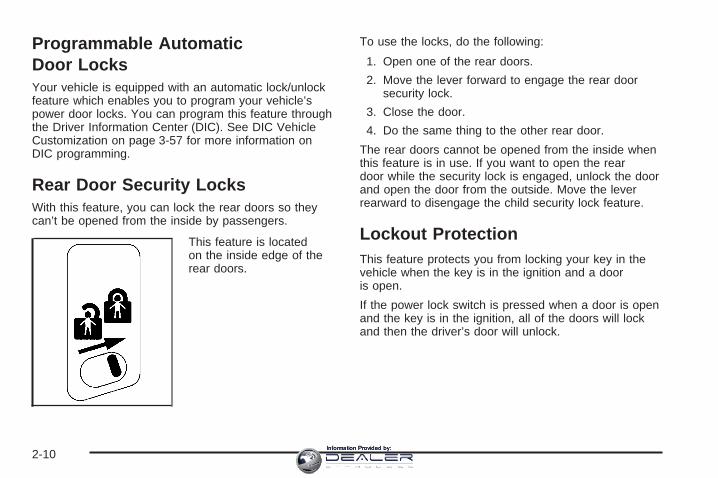
Programmable AutomaticDoor LocksYour vehicle is equipped with an automatic lock/unlockfeature which enables you to program your vehicle’spower door locks. You can program this feature throughthe Driver Information Center (DIC). See DIC VehicleCustomization on page 3-57 for more information onDIC programming.
Rear Door Security LocksWith this feature, you can lock the rear doors so theycan’t be opened from the inside by passengers.
This feature is locatedon the inside edge of therear doors.
To use the locks, do the following:
1. Open one of the rear doors.
2. Move the lever forward to engage the rear doorsecurity lock.
3. Close the door.
4. Do the same thing to the other rear door.
The rear doors cannot be opened from the inside whenthis feature is in use. If you want to open the reardoor while the security lock is engaged, unlock the doorand open the door from the outside. Move the leverrearward to disengage the child security lock feature.
Lockout ProtectionThis feature protects you from locking your key in thevehicle when the key is in the ignition and a dooris open.
If the power lock switch is pressed when a door is openand the key is in the ignition, all of the doors will lockand then the driver’s door will unlock.
2-10Information Provided by:

Midgate ®
{CAUTION:
It can be dangerous to drive with the cargoarea covered and the tailgate and the midgate ®
open because carbon monoxide (CO) gas cancome into your vehicle. You can not see orsmell CO. It can cause unconsciousness andeven death. If you must drive with the cargocovers on and the tailgate and midgate ®
open or if electrical wiring or other cableconnections must pass through the sealbetween the body and the midgate ®:
• Make sure all windows are shut.• Turn the fan on your heating or cooling
system to its highest speed on the settingthat brings in outside air. This will forceoutside air into your vehicle. See DualAutomatic Climate Control System onpage 3-22.
• If you have air outlets on or under theinstrument panel, open them all the way.See Engine Exhaust on page 2-36.
Midgate ® OperationYour vehicle is equipped with a midgate and a removablerear glass panel. The midgate allows you to extend thelength of your vehicle’s cargo area.
The following are the main components of the midgatesystem:
A. Latch LeversB. Grab HandlesC. Glass-Catch
Release Button
D. Glass Lock KnobsE. Window Retaining TabsF. Midgate Release HandleG. Window Alignment Arrows
2-11Information Provided by:

Rear Glass Removal and Storage
{CAUTION:
If the removable rear glass is not storedproperly, it could be thrown about the vehiclein a crash or sudden maneuver. People in thevehicle could be injured. Whenever you storethe rear glass in the vehicle, always be surethat it is stored securely in the midgatestorage pocket.
Do not remove the rear glass when the rear defroster ison. If you remove the rear glass with the rear defrosteron, you may see a discharge spark coming fromthe latch area.
To remove the rear glass do the following:1. Fold the rear seats. See Rear Seat Operation on
page 1-7 for more information. The front seatsmay have to be moved forward slightly to allow therear seats to fold completely.Although the rear glass can be removed withoutfolding the rear seats, you will not be able to accessthe rear glass storage pocket. Be sure to fold theseats before removing the rear glass.
2. Squeeze and pull down the latch levers (A), locatednear the upper corners of the rear glass, to unlatch.Once unlatched, the glass-catch release button (C)will catch the rear glass and prevent it fromfalling forward.
2-12Information Provided by:

3. While holding the rear glass in place, press theglass-catch release button (C) and pull the topof the rear glass toward you using the grabhandle(s) (B) located at the top of the rear glass.
4. With the rear glass tilted toward you, lift it out fromthe lower window frame channel. Use the grabhandles to assist you in removing the rear glass.
2-13Information Provided by:

5. Load the rear glass into the storage pocket in themidgate, guiding the lower edge of the rear glassbehind the three rear glass retaining tabs (E).Hold the rear glass flat against the storage pocket,with grab handles facing you, until the next step.
6. Turn both glass lock knobs (D), located at bothtop corners of the storage pocket, to the lockedposition. Push in on the corner of the rear glass toallow the lock knob to engage more easily.
2-14Information Provided by:

Once both glass lock knobs are in the lockedposition, the rear glass is securely stored.
7. Push both latch levers up to the locked position.You should hear a click when each latch leverlocks correctly.The rear seats can be returned to the normalposition when the rear glass is out and storedproperly in the storage pocket.
Reinstalling the Rear GlassTo reinstall the rear glass, do the following:
1. Squeeze and pull down the latch levers (A), locatednear the upper corners of the rear glass, to unlatch.
2. Hold the rear glass in place with one hand and turnthe glass lock knobs, located at both top corners ofthe glass storage pocket, to the unlocked position.
3. Pull the rear glass out from the storage pocket usingthe grab handles.
2-15Information Provided by:
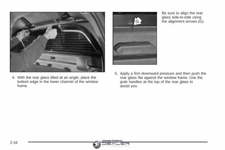
4. With the rear glass tilted at an angle, place thebottom edge in the lower channel of the windowframe.
Be sure to align the rearglass side-to-side usingthe alignment arrows (G).
5. Apply a firm downward pressure and then push therear glass flat against the window frame. Use thegrab handles at the top of the rear glass toassist you.
2-16Information Provided by:
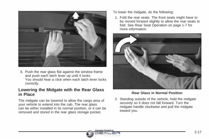
6. Push the rear glass flat against the window frameand push each latch lever up until it locks.You should hear a click when each latch lever lockscorrectly.
Lowering the Midgate with the Rear Glassin PlaceThe midgate can be lowered to allow the cargo area ofyour vehicle to extend into the cab. The rear glasscan be either installed in its normal position, or it can beremoved and stored in the rear glass storage pocket.
To lower the midgate, do the following:
1. Fold the rear seats. The front seats might have tobe moved forward slightly to allow the rear seats tofold. See Rear Seat Operation on page 1-7 formore information.
2. Standing outside of the vehicle, hold the midgatesecurely so it does not fall forward. Turn themidgate handle clockwise and pull the midgatetoward you.
Rear Glass in Normal Position
2-17Information Provided by:

3. Lower the midgate until it is flat.
Lowering the Midgate with the Rear Glassin the Storage Pocket
Rear Glass Stored in Glass Storage Pocket
2-18Information Provided by:

This procedure works the same as the proceduredescribed previously, but when you lower the midgatewith the rear glass in the stored position, you will noticethat the entire crossbar will lower with the midgate.This is completely normal; however, since the crossbarlowers with the midgate, it will be heavier. As youlower the midgate be ready for the extra weight and donot let the midgate fall as you lower it.
Raising the MidgateTo return the midgate to its normal position, raise themidgate up with a firm swinging motion until it latchesinto place securely. This will help to ensure that themidgate closes with enough force to engage the latches.
If the rear glass is removed and you would like to putit back, do so using the instructions given previously.
TailgateUse the ignition/door key to unlock/lock the tailgate.
Open the tailgate by lifting up on its handle while pullingthe tailgate toward you.
To shut the tailgate, firmly push it upward until itlatches. Push and pull on the tailgate to be sure it islatched securely.
Midgate Lowered with Crossbar Attached
2-19Information Provided by:

Tailgate RemovalThe tailgate can be removed to allow for differentloading situations. Although the tailgate can be removedwithout assistance, you may want someone to assistyou with the removal to avoid possible damage tothe vehicle.
To remove the tailgate, do the following:
1. Hold the tailgate up, slightly raised.
2. Release the retainingcable clip by lifting thecable so it is levelwith the ground andthen push the cable cliptoward the vehicle. 3. Raise the tailgate at a slight upward angle,
pull back on the tailgate at the right edge soit releases from the block hinge and then move thetailgate to the right to release the left edge.
Reverse the above procedure to reinstall. Make sure thetailgate is secure.
2-20Information Provided by:
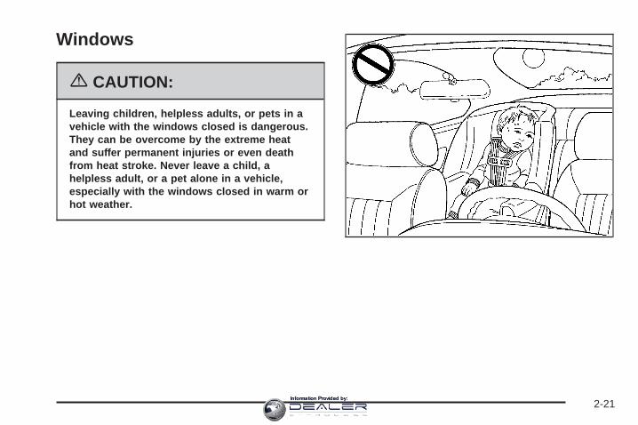
Windows
{CAUTION:
Leaving children, helpless adults, or pets in avehicle with the windows closed is dangerous.They can be overcome by the extreme heatand suffer permanent injuries or even deathfrom heat stroke. Never leave a child, ahelpless adult, or a pet alone in a vehicle,especially with the windows closed in warm orhot weather.
2-21Information Provided by:

Power Windows
The controls for the power windows are located on thearmrest on each of the side doors. The switchesoperate the windows when the ignition is in RUN,ACCESSORY or while Retained Accessory Power(RAP) is active. See Retained Accessory Power (RAP)on page 2-26.
The driver’s door also has a switch for each of thepassenger’s windows.
Press the top of the switch to lower the window.Pull up the top of the switch to raise the window.
Express-Down WindowsThe driver and front passenger windows also have anexpress-down feature that allows the windows tobe lowered without holding the switch. Press down fullyon the window switch, then release, to activate theexpress-down mode. This mode can be canceled at anytime by pulling up on the switch. To open the windowpartway, press the switch to the first position untilthe window is at the desired position.
Window Lockout
o (Window Lockout): Press the lockout switch toprevent passengers from operating the power windowsfrom their switches. A light in the lockout switch willcome on to show that the switch has been activated.Press the lockout switch again to return to normaloperation.
2-22Information Provided by:
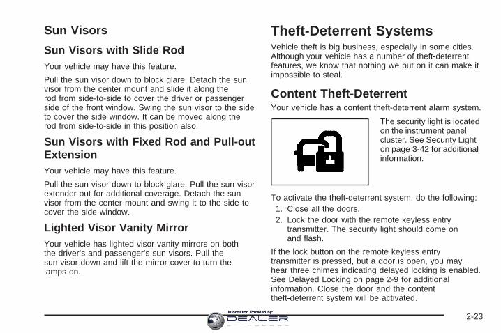
Sun Visors
Sun Visors with Slide RodYour vehicle may have this feature.
Pull the sun visor down to block glare. Detach the sunvisor from the center mount and slide it along therod from side-to-side to cover the driver or passengerside of the front window. Swing the sun visor to the sideto cover the side window. It can be moved along therod from side-to-side in this position also.
Sun Visors with Fixed Rod and Pull-outExtensionYour vehicle may have this feature.
Pull the sun visor down to block glare. Pull the sun visorextender out for additional coverage. Detach the sunvisor from the center mount and swing it to the side tocover the side window.
Lighted Visor Vanity MirrorYour vehicle has lighted visor vanity mirrors on boththe driver’s and passenger’s sun visors. Pull thesun visor down and lift the mirror cover to turn thelamps on.
Theft-Deterrent SystemsVehicle theft is big business, especially in some cities.Although your vehicle has a number of theft-deterrentfeatures, we know that nothing we put on it can make itimpossible to steal.
Content Theft-DeterrentYour vehicle has a content theft-deterrent alarm system.
The security light is locatedon the instrument panelcluster. See Security Lighton page 3-42 for additionalinformation.
To activate the theft-deterrent system, do the following:1. Close all the doors.2. Lock the door with the remote keyless entry
transmitter. The security light should come onand flash.
If the lock button on the remote keyless entrytransmitter is pressed, but a door is open, you mayhear three chimes indicating delayed locking is enabled.See Delayed Locking on page 2-9 for additionalinformation. Close the door and the contenttheft-deterrent system will be activated.
2-23Information Provided by:

If a locked door is opened without using the remotekeyless entry transmitter or OnStar, if equipped with anactive subscription, the alarm will go off. Your vehicle’slamps will flash and the horn will sound for abouttwo minutes, then will turn off to save the battery power.If this occurs, you can turn off the alarm by pressingunlock on the remote keyless entry transmitter orby placing the key in the ignition and turning itto START.
If your vehicle has a Driver Information Center (DIC),you can customize your alarm warning. See DICVehicle Customization on page 3-57 for additionalinformation.
The horn may chirp for 10 seconds before the alarmgoes off if the theft-deterrent system is activated usingthe remote keyless entry transmitter and the driver’sdoor is opened. If this occurs, you can turn off the alarmby pressing unlock on the remote keyless entrytransmitter or by placing the key in the ignition andturning it to START.
Here is how to avoid setting off the alarm by accident:• If you do not want to activate the theft-deterrent
system, the vehicle should be locked with thedoor key after the doors are closed.
• Always unlock a door with the remote keyless entrytransmitter.
If you set off the alarm by accident, turn off the alarmby pressing unlock on the remote keyless entrytransmitter or by placing the key in the ignition andturning it to START.
Testing the AlarmThe alarm can be tested by following these steps:
1. From inside the vehicle, activate the system bylocking the doors with the remote keyless entrytransmitter.
2. Wait for the security light to go out.
3. Unlock the door with the manual door lock andopen the door. This should set off the alarm.
4. Turn off the alarm by pressing unlock on the remotekeyless entry transmitter or by placing the key inthe ignition and turning it to START.
If the alarm does not sound when it should, but thevehicle’s headlamps flash, check to see if the hornworks. The horn fuse may be blown. To replace thefuse, see Instrument Panel Fuse Block on page 5-110and Underhood Fuse Block on page 5-113.
If the alarm does not sound or the vehicle’s headlampsdo not flash, see your dealer for service.
2-24Information Provided by:

Passlock ®
Your vehicle is equipped with the Passlock®
theft-deterrent system.
Passlock® is a passive theft-deterrent system.Passlock® enables fuel if the ignition lock cylinder isturned with a valid key. If a correct key is not used or theignition lock cylinder is tampered with, the fuel systemis disabled and the vehicle will not start.
During normal operation, the security light will turn offapproximately five seconds after the key is turned to RUN.
If the engine stalls and the security light flashes, waitabout 10 minutes until the light stops flashing beforetrying to restart the engine. Remember to releasethe key from START as soon as the engine starts.
If the engine does not start after three tries, the vehicleneeds service.
If the engine is running and the security light comes on,you will be able to restart the engine if you turn theengine off. However, your Passlock® system is notworking properly and must be serviced by your dealer.Your vehicle is not protected by Passlock® at this time.You may also want to check the fuse. See Fuses andCircuit Breakers on page 5-109. See your dealer forservice.
In an emergency, call the Roadside Assistance Center.See Roadside Service on page 7-6.
Starting and OperatingYour Vehicle
New Vehicle Break-InNotice: Your vehicle does not need an elaboratebreak-in. But it will perform better in the long run ifyou follow these guidelines:• Keep your speed at 55 mph (88 km/h) or less for
the first 500 miles (805 km).• Do not drive at any one constant speed, fast or
slow, for the first 500 miles (805 km). Do notmake full-throttle starts. Avoid downshifting tobrake, or slow, the vehicle.
• Avoid making hard stops for the first 200 miles(322 km) or so. During this time your new brakelinings are not yet broken in. Hard stops with newlinings can mean premature wear and earlierreplacement. Follow this breaking-in guidelineevery time you get new brake linings.
• Do not tow a trailer during break-in. See Towinga Trailer on page 4-50 for the trailer towingcapabilities of your vehicle and moreinformation.
Following break-in, engine speed and load can begradually increased.
2-25Information Provided by:

Ignition Positions
Use the key to turn the ignition switch to four differentpositions.
A (LOCK): This position locks the ignition andtransmission. It is a theft-deterrent feature. You will onlybe able to remove the key when the ignition is turnedto LOCK.
Notice: Using a tool to force the key from theignition switch could cause damage or break thekey. Use the correct key and turn the key only withyour hand. Make sure the key is all the way in.
If it is, turn the steering wheel left and right whileyou turn the key hard. If none of this works,then your vehicle needs service.
B (ACCESSORY): This position lets you use thingslike the radio and the windshield wipers when theengine is off.
Notice: Lengthy operation of features such as theradio in the accessory ignition position may drainthe battery and prevent your vehicle from starting.Do not operate your vehicle in the accessory ignitionposition for a long period of time.
C (RUN): This is the position for driving.
D (START): This position starts the engine.
Retained Accessory Power (RAP)The Retained Accessory Power (RAP) feature will allowcertain features on your vehicle to continue to workfor up to 10 minutes after the ignition key is turned toLOCK or until one of the doors is opened.
2-26Information Provided by:

Starting the EngineYour vehicle is equipped with Starter Motor Control.This feature assists in starting the engine and protectsthe electrical system. This feature may cause the engineto crank even after the ignition key is not in START.
Move your shift lever to PARK (P) or NEUTRAL (N).Your engine will not start in any other position — that isa safety feature. To restart when you are alreadymoving, use NEUTRAL (N) only.
Notice: Do not try to shift to PARK (P) if yourvehicle is moving. If you do, you could damage thetransmission. Shift to PARK (P) only when yourvehicle is stopped.
1. With your foot off the accelerator pedal, turn theignition key to START. When the engine starts,let go of the key. The idle speed will go down asyour engine gets warm.
Notice: Holding your key in START for longer than15 seconds at a time will disengage the startermotor, cause your battery to be drained muchsooner, and add excessive heat that can damageyour starter motor. Try not to hold the key inSTART for longer than 15 seconds and wait about15 seconds between each try to help avoid drainingyour battery or damaging your starter.
2. If it does not start within 10 seconds, push theaccelerator pedal all the way to the floor, while youhold the ignition key in START. When the enginestarts, let go of the key and let up on the acceleratorpedal. Wait about 15 seconds between each try.
When starting your engine in very cold weather(below 0°F or −18°C), do this:
1. With your foot off the accelerator pedal, turn theignition key to START and hold it there up to15 seconds. When the engine starts, let go ofthe key.
2. If your engine still will not start, or starts but thenstops, it could be flooded with too much gasoline.Try pushing your accelerator pedal all the way to thefloor and holding it there as you hold the key inSTART for about three seconds. When the enginestarts, let go of the key and accelerator. If thevehicle starts briefly but then stops again, do thesame thing, but this time keep the pedal downfor five or six seconds. This clears the extragasoline from the engine.
Notice: Your engine is designed to work with theelectronics in your vehicle. If you add electricalparts or accessories, you could change the way theengine operates. Before adding electrical equipment,check with your dealer. If you do not, your enginemight not perform properly. Any resulting damagewould not be covered by your vehicle’s warranty.
2-27Information Provided by:
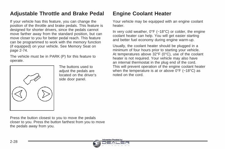
Adjustable Throttle and Brake PedalIf your vehicle has this feature, you can change theposition of the throttle and brake pedals. This feature isdesigned for shorter drivers, since the pedals cannotmove farther away from the standard position, but canmove closer to you for better pedal reach. This featurecan be programmed to work with the memory function(if equipped) on your vehicle. See Memory Seat onpage 2-74.
The vehicle must be in PARK (P) for this feature tooperate.
The buttons used toadjust the pedals arelocated on the driver’sside door panel.
Press the button closest to you to move the pedalscloser to you. Press the button farthest from you to movethe pedals away from you.
Engine Coolant HeaterYour vehicle may be equipped with an engine coolantheater.
In very cold weather, 0°F (−18°C) or colder, the enginecoolant heater can help. You will get easier startingand better fuel economy during engine warm-up.
Usually, the coolant heater should be plugged in aminimum of four hours prior to starting your vehicle.At temperatures above 32°F (0°C), use of the coolantheater is not required. Your vehicle may also havean internal thermostat in the plug end of the cord.This will prevent operation of the engine coolant heaterwhen the temperature is at or above 0°F (−18°C) asnoted on the cord.
2-28Information Provided by:

To Use the Engine Coolant Heater1. Turn off the engine.
2. Open the hood and unwrap the electrical cord.The cord is located on the driver’s side of theengine compartment, near the power steering fluidreservoir.
3. Plug it into a normal, grounded 110-volt AC outlet.
{CAUTION:
Plugging the cord into an ungrounded outletcould cause an electrical shock. Also, thewrong kind of extension cord could overheatand cause a fire. You could be seriouslyinjured. Plug the cord into a properly groundedthree-prong 110-volt AC outlet. If the cord willnot reach, use a heavy-duty three-prongextension cord rated for at least 15 amps.
4. Before starting the engine, be sure to unplug andstore the cord as it was before to keep it awayfrom moving engine parts. If you do not, it couldbe damaged.
How long should you keep the coolant heater pluggedin? The answer depends on the outside temperature,the kind of oil you have, and some other things.Instead of trying to list everything here, we ask thatyou contact your dealer in the area where you will beparking your vehicle. The dealer can give you thebest advice for that particular area.
2-29Information Provided by:

Automatic Transmission OperationYour vehicle is equipped with an automatic transmissionand features an electronic shift position indicatorlocated within the instrument panel cluster.
There are several different positions for your shift lever.
PARK (P): This position locks your drive wheels.It is the best position to use when you start yourengine because your vehicle cannot move easily.
{CAUTION:
It is dangerous to get out of your vehicle if theshift lever is not fully in PARK (P) with theparking brake firmly set. Your vehicle can roll.
Do not leave your vehicle when the engine isrunning unless you have to. If you have left theengine running, the vehicle can move suddenly.You or others could be injured. To be sure yourvehicle will not move, even when you are onfairly level ground, always set your parkingbrake and move the shift lever to PARK (P).See Shifting Into Park (P) on page 2-34. If youare pulling a trailer, see Towing a Trailer onpage 4-50.
2-30Information Provided by:

REVERSE (R): Use this gear to back up.
Notice: Shifting to REVERSE (R) while your vehicleis moving forward could damage the transmission.The repairs would not be covered by your warranty.Shift to REVERSE (R) only after your vehicle isstopped.
To rock your vehicle back and forth to get out of snow,ice or sand without damaging your transmission,see If Your Vehicle is Stuck in Sand, Mud, Ice or Snowon page 4-42.
NEUTRAL (N): In this position, your engine does notconnect with the wheels. To restart when you arealready moving, use NEUTRAL (N) only.
{CAUTION:
Shifting into a drive gear while your engine isrunning at high speed is dangerous. Unlessyour foot is firmly on the brake pedal, yourvehicle could move very rapidly. You couldlose control and hit people or objects. Do notshift into a drive gear while your engine isrunning at high speed.
Notice: Shifting out of PARK (P) or NEUTRAL (N)with the engine running at high speed may damagethe transmission. The repairs would not be coveredby your warranty. Be sure the engine is not runningat high speed when shifting your vehicle.
DRIVE (D): This position is for normal driving. If youneed more power for passing, and you are:
• Going less than about 35 mph (55 km/h),push your accelerator pedal about halfway down.
• Going about 35 mph (55 km/h) or more,push the accelerator all the way down.
You will shift down to the next gear and have morepower.
DRIVE (D) can be used when towing a trailer, carrying aheavy load, driving on steep hills or for off-road driving.You may want to shift the transmission to THIRD (3) or,if necessary, a lower gear selection if the transmissionshifts too often.
THIRD (3): This position is also used for normal driving,however it offers more power and lower fuel economythan DRIVE (D).
2-31Information Provided by:

SECOND (2): This position gives you more power butlower fuel economy. You can use SECOND (2) onhills. It can help control your speed as you go downsteep mountain roads, but then you would also want touse your brakes off and on.
If you manually select SECOND (2), the transmissionwill drive in second gear. You may use this featurefor reducing the speed of the rear wheels when you aretrying to start your vehicle from a stop on slipperyroad surfaces. Once the vehicle is moving, shift intoDRIVE (D).
FIRST (1): This position gives you even more power,but lower fuel economy than SECOND (2). You can useit on very steep hills, or in deep snow or mud. If theshift lever is put in FIRST (1) while the vehicle is movingforward, the vehicle will not shift into first gear untilthe vehicle is going slowly enough.
Notice: Spinning the tires or holding the vehicle inone place on a hill using only the acceleratorpedal may damage the transmission. If you arestuck, do not spin the tires. When stopping on a hill,use the brakes to hold the vehicle in place.
On cold days, approximately 32°F (0°C) or colder, yourtransmission is designed to shift differently until theengine reaches normal operating temperature. This isintended to improve heater performance.
Tow/Haul ModeYour vehicle is equippedwith a tow/haul mode.The button for this featureis located on the end ofthe column shift lever.
You can use this feature to assist when towing orhauling a heavy load. See “Tow/Haul Mode” underTowing a Trailer on page 4-50 for more information.
The tow/haul mode also interacts with the Road SensingSuspension (RSS) feature to enhance the ride whentrailering or with a loaded vehicle. See Road SensingSuspension on page 4-9.
2-32Information Provided by:

Parking BrakeTo set the parking brake, hold the regular brake pedaldown with your right foot. Push down the parkingbrake pedal with your left foot.
A chime will activate and the warning light will flashwhen the parking brake is applied and the vehicleis moving at least 3 mph (5 km/h) for at leastthree seconds.
To release the parking brake, hold the regular brakepedal down. Pull the bottom edge of the lever, locatedabove the parking brake pedal, with the parkingbrake symbol, to release the parking brake.
If the ignition is on when the parking brake is released,the brake system warning light will go off.
Notice: Driving with the parking brake on canoverheat the brake system and cause prematurewear or damage to brake system parts. Verify thatthe parking brake is fully released and the brakewarning light is off before driving.
If you are towing a trailer and are parking on any hill,see Towing a Trailer on page 4-50.
2-33Information Provided by:
Shifting Into Park (P)
{CAUTION:
It can be dangerous to get out of your vehicle ifthe shift lever is not fully in PARK (P) with theparking brake firmly set. Your vehicle can roll.If you have left the engine running, the vehiclecan move suddenly. You or others could beinjured. To be sure your vehicle will not move,even when you are on fairly level ground, usethe steps that follow. If you are pulling a trailer,see Towing a Trailer on page 4-50.
1. Hold the brake pedal down with your right foot andset the parking brake with your left foot.
2. Move the shift lever into PARK (P) by pulling theshift lever toward you and moving it up as far as itwill go.
3. Turn the ignition key to LOCK.
4. Remove the key and take it with you. If you canleave your vehicle with the ignition key in yourhand, your vehicle is in PARK (P).
Leaving Your Vehicle With the EngineRunning
{CAUTION:
It can be dangerous to leave your vehicle withthe engine running. Your vehicle could movesuddenly if the shift lever is not fully inPARK (P) with the parking brake firmly set.And, if you leave the vehicle with the enginerunning, it could overheat and even catch fire.You or others could be injured. Do not leaveyour vehicle with the engine running.
If you have to leave your vehicle with the enginerunning, be sure your vehicle is in PARK (P) and theparking brake is firmly set before you leave it. After youmove the shift lever into PARK (P), hold the regularbrake pedal down. Then, see if you can move theshift lever away from PARK (P) without first pulling ittoward you. If you can, it means that the shift leverwas not fully locked into PARK (P).
2-34Information Provided by:

Torque LockIf you are parking on a hill and you do not shift yourvehicle into PARK (P) properly, the weight of the vehiclemay put too much force on the parking pawl in thetransmission. You may find it difficult to pull the shiftlever out of PARK (P). This is called torque lock.To prevent torque lock, set the parking brake and thenshift into PARK (P) properly before you leave thedriver’s seat. To find out how, see Shifting Into Park (P)on page 2-34.
When you are ready to drive, move the shift lever out ofPARK (P) before you release the parking brake.
If torque lock does occur, you may need to have anothervehicle push yours a little uphill to take some of thepressure from the parking pawl in the transmission,so you can pull the shift lever out of PARK (P).
Shifting Out of Park (P)Your vehicle has an automatic transmission shift lockcontrol system. You have to fully apply your regularbrakes before you can shift from PARK (P) when theignition is in RUN. See Automatic TransmissionOperation on page 2-30.
If you cannot shift out of PARK (P), ease pressure onthe shift lever and push the shift lever all the way upinto PARK (P) as you maintain brake application.Then, move the shift lever into the gear you want.
If you ever hold the brake pedal down but still cannotshift out of PARK (P), try this:
1. Turn the key to ACCESSORY. There is no shiftinterlock in this key position.
2. Apply and hold the brake until the end of Step 4.
3. Shift the vehicle to NEUTRAL (N).
4. Start the vehicle and then shift to the drive gearyou want.
5. Have the system fixed as soon as possible.
2-35Information Provided by:

Parking Over Things That Burn
{CAUTION:
Things that can burn could touch hot exhaustparts under your vehicle and ignite. Do notpark over papers, leaves, dry grass, or otherthings that can burn.
Engine Exhaust
{CAUTION:
Engine exhaust can kill. It contains the gascarbon monoxide (CO), which you cannot see orsmell. It can cause unconsciousness and death.
You might have exhaust coming in if:• Your exhaust system sounds strange or
different.• Your vehicle gets rusty underneath.• Your vehicle was damaged in a collision.• Your vehicle was damaged when driving
over high points on the road or over roaddebris.
• Repairs were not done correctly.• Your vehicle or exhaust system had been
modified improperly.
If you ever suspect exhaust is coming into yourvehicle:
• Drive it only with all the windows down toblow out any CO; and
• Have your vehicle fixed immediately.
2-36Information Provided by:

Running the Engine While ParkedIt is better not to park with the engine running. But if youever have to, here are some things to know.
{CAUTION:
Idling the engine with the climate controlsystem off could allow dangerous exhaust intoyour vehicle. See the earlier caution underEngine Exhaust on page 2-36.
Also, idling in a closed-in place can let deadlycarbon monoxide (CO) into your vehicle even ifthe climate control fan is at the highest setting.One place this can happen is a garage.Exhaust — with CO — can come in easily.NEVER park in a garage with the enginerunning.
Another closed-in place can be a blizzard.See Winter Driving on page 4-38.
{CAUTION:
It can be dangerous to get out of your vehicleif the shift lever is not fully in PARK (P) withthe parking brake firmly set. Your vehicle canroll. Do not leave your vehicle when the engineis running unless you have to. If you have leftthe engine running, the vehicle can movesuddenly. You or others could be injured.To be sure your vehicle will not move, evenwhen you are on fairly level ground, always setyour parking brake and move the shift leverto PARK (P).
Follow the proper steps to be sure your vehicle will notmove. See Shifting Into Park (P) on page 2-34.
If you are pulling a trailer, see Towing a Trailer onpage 4-50.
2-37Information Provided by:
Mirrors
Automatic Dimming Rearview Mirrorwith OnStar ® and CompassYour vehicle may have an automatic-dimming rearviewmirror with a compass and the OnStar® system.
There are three additional buttons for the OnStar®
system. See your dealer for more information on thesystem and how to subscribe to OnStar®. See OnStar®
System on page 2-46 for more information about theservices OnStar® provides.
Mirror OperationWhen turned on, this mirror automatically dims to theproper level to minimize glare from any headlampsbehind you after dark.
P(On/Off): This is the on/off button for the automaticdimming feature and compass. Press the far leftbutton, located below the mirror face, for up tothree seconds to turn the feature on and off. A light onthe mirror will be lit while the feature is turned on.
Compass OperationPress the on/off button once to turn the compasson or off.
There is a compass display in the window in the upperright corner of the mirror face. The compass displaysa maximum of two characters. For example, “NE”is displayed for north-east.
Compass CalibrationPress and hold the on/off button down for nine secondsto activate the compass calibration mode. CAL willbe displayed in the compass window on the mirror.
The compass can be calibrated by driving the vehiclein circles at 5 mph (8 km/h) or less until the displayreads a direction.
Compass VarianceCompass variance is the difference between earth’smagnetic north and true geographic north. The mirror isset to zone eight upon leaving the factory. It will benecessary to adjust the compass to compensatefor compass variance if you live outside zone eight.Under certain circumstances, such as during a longdistance cross-country trip, it will be necessary to adjustfor compass variance. If not adjusted to account forcompass variance, your compass could give falsereadings.
2-38Information Provided by:

To adjust for compass variance, do the following:1. Find your current location and variance zone
number on the map.
2. Press and hold the on/off button for six seconds.Release the button when ZONE is displayed.The number shown is the current zone number.
3. Scroll through the zone numbers that appear in thecompass/temperature window on the mirror bypressing the on/off button. Once you find yourzone number, release the button. After aboutfour seconds, the mirror will return to the compassdisplay, and the new zone number will be set.
Automatic Dimming Rearview Mirrorwith OnStar ®, Compass andTemperature DisplayYour vehicle may have this feature. When on, theautomatic dimming mirror dims to the proper level tominimize glare from lights behind you after dark.
The mirror has a dual display in the upper right cornerof the mirror face that shows the compass readingand the outside temperature.
Control buttons for the OnStar® system are at thebottom of the mirror. See OnStar® System onpage 2-46 for more information about the servicesOnStar® provides.
P (On/Off): This is the on/off button.
2-39Information Provided by:

Temperature and Compass DisplayPress the on/off button, located to the far left, briefly toturn the compass/temperature display on or off.
If the display reads CAL, the compass needs to becalibrated. For more information, see “CompassCalibration” following.
To adjust between Fahrenheit and Celsius, do thefollowing:
1. Press and hold the on/off button for approximatelyfour seconds until either a flashing F or C appears.
2. Press the button again to change the display to thedesired unit of measurement. After approximatelyfour seconds of inactivity, the new unit will be lockedin and the compass/temperature display will return.
If an abnormal temperature reading is displayed for anextended period of time, please see your GM dealer.Under certain circumstances, a delay in updatingthe temperature is normal.
Automatic Dimming Mirror OperationThe automatic dimming mirror function is turned onautomatically each time the ignition is started. To operatethe automatic dimming mirror, do the following:
1. Make sure the green indicator light, located to the leftof the on/off button, is lit. If it is not, press and holdthe on/off button for approximately six seconds untilthe green light comes on, indicating that the mirror isin automatic dimming mode.
2. Turn off the automatic dimming mirror functionby pressing and holding the on/off button forapproximately six seconds, until the green indicatorlight turns off.
Compass VarianceThe mirror is set in zone eight upon leaving the factory.It will be necessary to adjust the compass tocompensate for compass variance if the vehicle isoutside of zone eight. Under certain circumstances, asduring a long distance cross-country trip, it will benecessary to adjust for compass variance. Compassvariance is the difference between earth’s magneticnorth and true geographic north. If not adjustedto account for compass variance, the compass couldgive false readings.
2-40Information Provided by:

To adjust for compass variance, do the following:1. Find your current location and variance zone
number on the following zone map.
2. Press and hold the on/off button until a Z and azone number appears in the display. The compassis now in zone mode.
3. Keep pressing the on/off button until the desiredzone number appears in the display. Release thebutton. After approximately four seconds ofinactivity, the new zone number will be locked inand the compass/temperature display will return.
4. Calibrate the compass as described next.
Compass CalibrationThe compass may need calibration if one of thefollowing occurs:
• After approximately five seconds, the display doesnot show a compass heading, N for North, forexample, there may be a strong magnetic fieldinterfering with the compass. Such interference maybe caused by a magnetic antenna mount, magneticnote pad holder, or a similar magnetic item.
• The compass does not display the correct headingand the compass zone variance is set correctly.
In order to calibrate, CAL must be displayed in themirror compass windows. If CAL is not displayed, pushthe on/off button for approximately 12 seconds oruntil CAL is displayed.
The compass can be calibrated by driving the vehiclein circles at 5 mph (8 km/h) or less until the displayreads a direction.
2-41Information Provided by:
Passenger Airbag IndicatorThe vehicle may be equipped with a passenger airbagindicator, on the mirror glass, just above the buttons.For more information, see Passenger Sensing Systemon page 1-60 and Passenger Airbag Status Indicatoron page 3-32.
Cleaning the MirrorWhen cleaning the mirror, use a paper towel or similarmaterial dampened with glass cleaner. Do not sprayglass cleaner directly on the mirror as that may causethe liquid cleaner to enter the mirror housing.
Automatic Dimming Rearview Mirrorwith CompassYour vehicle may have an automatic-dimming rearviewmirror with a compass.
Mirror OperationWhen turned on, this mirror automatically dims to theproper level to minimize glare from any headlampsbehind you after dark.
P(On/Off): This is the on/off button for the automaticdimming feature and compass. Press the far leftbutton, located below the mirror face, for up tothree seconds to turn the feature on and off. A light onthe mirror will be lit while the feature is turned on.
Compass OperationPress the on/off button once to turn the compasson or off.
There is a compass display in the window in the upperright corner of the mirror face. The compass displaysa maximum of two characters. For example, “NE”is displayed for north-east.
Compass CalibrationPress and hold the on/off button down for nine secondsto activate the compass calibration mode. CAL willbe displayed in the compass window on the mirror.
The compass can be calibrated by driving the vehicle incircles at 5 mph (8 km/h) or less until the displayreads a direction.
Compass VarianceCompass variance is the difference between earth’smagnetic north and true geographic north. The mirror isset to zone eight upon leaving the factory. It will benecessary to adjust the compass to compensatefor compass variance if you live outside zone eight.Under certain circumstances, such as during a longdistance cross-country trip, it will be necessary to adjustfor compass variance. If not adjusted to account forcompass variance, your compass could give falsereadings.
2-42Information Provided by:

To adjust for compass variance, do the following:1. Find your current location and variance zone
number on the map.
2. Press and hold the on/off button for six seconds.Release the button when ZONE is displayed.The number shown is the current zone number.
3. Scroll through the zone numbers that appear in thecompass/temperature window on the mirror bypressing the on/off button. Once you find yourzone number, release the button. After aboutfour seconds, the mirror will return to the compassdisplay, and the new zone number will be set.
Outside Power MirrorsThe controls are locatedon the driver’s doorarmrest.
Move the upper selector switch to the left or right tochoose the mirror to be adjusted, then press the dots,located below the selector switch on the four-way controlpad, to adjust the direction of each mirror.
The mirrors may also include a memory functionwhich works in conjunction with the memory seats.See Memory Seat on page 2-74 for more information.
2-43Information Provided by:

Power Folding MirrorsTo fold or unfold the mirrors, move the selector switch,located above the mirror control, to the middle position.The mirror control will illuminate. Press the right orleft side of the mirror control to fold or unfold the mirrors.The mirror will adjust as it folds in and will repositionitself once it is unfolded.
If the mirrors are accidentally folded/unfolded manually,they may shake or flutter at normal driving speedsand may not stay in the unfolded position. If thishappens, the mirrors need to be reset. See “Resettingthe Power Folding Mirrors” next.
Resetting the Power Folding MirrorsThe power folding mirrors will need to be reset if:
• They are accidently manually folded/unfolded.
• The mirrors will not stay in the unfolded position.
• The mirrors shake and flutter at normal drivingspeeds.
To reset the power folding mirrors, fold and unfold themat least three times using the mirror controls. This willreset them to their normal detent position.
Outside Convex Mirror
{CAUTION:
A convex mirror can make things (like othervehicles) look farther away than they really are.If you cut too sharply into the right lane, youcould hit a vehicle on your right. Check yourinside mirror or glance over your shoulderbefore changing lanes.
The passenger’s side mirror is convex. A convexmirror’s surface is curved so more can be seen fromthe driver’s seat. It makes things in the mirror appearfarther away than they really are.
2-44Information Provided by:
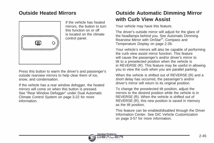
Outside Heated Mirrors
If the vehicle has heatedmirrors, the button to turnthis function on or offis located on the climatecontrol panel.
Press this button to warm the driver’s and passenger’soutside rearview mirrors to help clear them of ice,snow, and condensation.
If the vehicle has a rear window defogger, the heatedmirrors will come on when this button is pressed.See “Rear Window Defogger” under Dual AutomaticClimate Control System on page 3-22 for moreinformation.
Outside Automatic Dimming Mirrorwith Curb View AssistYour vehicle may have this feature.
The driver’s outside mirror will adjust for the glare ofthe headlamps behind you. See Automatic DimmingRearview Mirror with OnStar®, Compass andTemperature Display on page 2-39.
Your vehicle’s mirrors will also be capable of performingthe curb view assist mirror function. This featurewill cause the passenger’s and/or driver’s mirror totilt to a preselected position when the vehicle isin REVERSE (R). This feature may be useful in allowingyou to view the curb when you are parallel parking.
When the vehicle is shifted out of REVERSE (R) and ashort delay has occurred, the passenger’s and/ordriver’s mirror will return to its original position.
To change the preselected tilt position, adjust themirrors to the desired position while the vehicle is inREVERSE (R). When the vehicle is shifted out ofREVERSE (R), this new position is saved in memoryas the tilt position.
This feature can be enabled/disabled through the DriverInformation Center. See DIC Vehicle Customizationon page 3-57 for more information.
2-45Information Provided by:
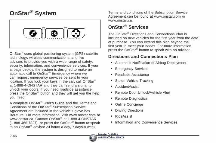
OnStar ® System
OnStar® uses global positioning system (GPS) satellitetechnology, wireless communications, and liveadvisors to provide you with a wide range of safety,security, information, and convenience services. If yourairbags deploy, the system is designed to make anautomatic call to OnStar® Emergency where wecan request emergency services be sent to yourlocation. If you lock your keys in the car, call OnStar®
at 1-888-4-ONSTAR and they can send a signal tounlock your doors. if you need roadside assistance,press the OnStar® button and they will get you the helpyou need.
A complete OnStar® User’s Guide and the Terms andConditions of the OnStar® Subscription ServiceAgreement are included in the vehicle’s glove boxliterature. For more information, visit www.onstar.com orwww.onstar.ca. Contact OnStar® at 1-888-4-ONSTAR(1-888-466-7827), or press the OnStar® button to speakto an OnStar® advisor 24 hours a day, 7 days a week.
Terms and conditions of the Subscription ServiceAgreement can be found at www.onstar.com orwww.onstar.ca.
OnStar ® ServicesThe OnStar® Directions and Connections Plan isincluded on new vehicles for the first year from the dateof purchase. You can extend this plan beyond thefirst year to meet your needs. For more information,press the OnStar® button to speak with an advisor.
Directions and Connections Plan• Automatic Notification of Airbag Deployment
• Emergency Services
• Roadside Assistance
• Stolen Vehicle Tracking
• AccidentAssist
• Remote Door Unlock/Vehicle Alert
• Remote Diagnostics
• Online Concierge
• Driving Directions
• RideAssist
• Information and Convenience Services
2-46Information Provided by:

OnStar ® Personal CallingAs an OnStar® subscriber, the Personal Callingcapability allows you to make hands-free calls using awireless system that is integrated into the vehicle.Calls can be placed nationwide using simple voicecommands with no additional contracts and no additionalroaming charges. To find out more about OnStar®
Personal Calling, refer to the OnStar® User’s Guidein the vehicle’s glove box, visit www.onstar.comor www.onstar.ca, or speak to an OnStar® advisor bypressing the OnStar® button or calling 1-888-4-ONSTAR(1-888-466-7827).
OnStar ® Virtual AdvisorYour vehicle may have Virtual Advisor. It is a feature ofOnStar® Personal Calling that uses your minutes toaccess weather, local traffic reports and sports updates.By pressing the phone button and giving a few simplevoice commands, you can browse through thevarious topics. Customize your information profile atwww.myonstar.com. See the OnStar® user’s guide formore information.
OnStar ® Steering Wheel Controls
Your vehicle may beequipped with a Talk/Mutebutton that can be usedto interact with OnStar®.See Audio Steering WheelControls on page 3-98for more information.
When calling into voice mail systems or to dial directorynumbers, press the control, wait for the “numberplease” response, say the number(s) to be dialed, waitfor the number(s) to be repeated and then say “dial.”
See the OnStar® User’s Guide for more information.
2-47Information Provided by:
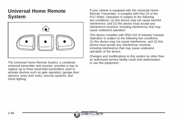
Universal Home RemoteSystem
The Universal Home Remote System, a combineduniversal transmitter and receiver, provides a way toreplace up to three hand-held transmitters used toactivate devices such as gate operators, garage dooropeners, entry door locks, security systems, andhome lighting.
If your vehicle is equipped with the Universal HomeRemote Transmitter, it complies with Part 15 of theFCC Rules. Operation is subject to the followingtwo conditions: (1) this device may not cause harmfulinterference, and (2) this device must accept anyinterference received, including interference that maycause undesired operation.
This device complies with RSS-210 of Industry Canada.Operation is subject to the following two conditions:(1) this device may not cause interference, and (2) thisdevice must accept any interference received,including interference that may cause undesiredoperation of the device.
Changes and modifications to this system by other thanan authorized service facility could void authorizationto use this equipment.
2-48Information Provided by:

Universal Home Remote SystemOperationDo not use the Universal Home Remote with anygarage door opener that does not have the “stop andreverse” feature. This includes any garage door openermodel manufactured before April 1, 1982. If youhave a newer garage door opener with rolling codes,please be sure to follow Steps 6 through 8 to completethe programming of your Universal Home RemoteTransmitter.
Read the instructions completely before attempting toprogram the Universal Home Remote. Because ofthe steps involved, it may be helpful to have anotherperson available to assist you in the programming steps.
Keep the original hand-held transmitter for use in othervehicles as well as for future Universal Home Remoteprogramming. It is also recommended that upon thesale of the vehicle, the programmed Universal HomeRemote buttons should be erased for security purposes.See “Erasing Universal Home Remote Buttons” laterin this section or, for assistance, see CustomerAssistance Offices on page 7-4.
Be sure that people and objects are clear of thegarage door or gate operator you are programming.When programming a garage door, it is advised to parkoutside of the garage.
It is recommended that a new battery be installed inyour hand-held transmitter for quicker and moreaccurate transmission of the radio-frequency signal.
2-49Information Provided by:

Programming Universal Home RemoteFollow these steps to program up to three channels:
1. Press and hold down the two outside UniversalHome Remote buttons, releasing only when theUniversal Home Remote indicator light beginsto flash, after 20 seconds. Do not hold down thebuttons for longer than 30 seconds and do notrepeat this step to program a second and/or thirdhand-held transmitter to the remaining two UniversalHome Remote buttons.
2. Position the end of your hand-held transmitterabout 1 to 3 inches (3 to 8 cm) away from theUniversal Home Remote buttons while keeping theindicator light in view.
3. Simultaneously press and hold both the desiredUniversal Home Remote button and the hand-heldtransmitter button. Do not release the buttonsuntil Step 4 has been completed.Some entry gates and garage door openers mayrequire you to substitute Step 3 with the procedurenoted in “Gate Operator and CanadianProgramming” later in this section.
4. The indicator light will flash slowly at first and thenrapidly after Universal Home Remote successfullyreceives the frequency signal from the hand-heldtransmitter. Release both buttons.
5. Press and hold the newly-trained Universal HomeRemote button and observe the indicator light.If the indicator light stays on constantly,programming is complete and your device shouldactivate when the Universal Home Remote buttonis pressed and released.To program the remaining two Universal HomeRemote buttons, begin with Step 2 under“Programming Universal Home Remote.”Do not repeat Step 1 as this will erase all of theprogrammed channels.If the indicator light blinks rapidly for two secondsand then turns to a constant light, continue withSteps 6 through 8 following to complete theprogramming of a rolling-code equipped device,most commonly, a garage door opener.
2-50Information Provided by:

6. Locate in the garage, the garage door openerreceiver (motor-head unit). Locate the “Learn”or “Smart” button. This can usually be found wherethe hanging antenna wire is attached to themotor-head unit.
7. Firmly press and release the “Learn” or “Smart”button. The name and color of the button mayvary by manufacturer.You will have 30 seconds to start Step 8.
8. Return to the vehicle. Firmly press and hold theprogrammed Universal Home Remote button fortwo seconds, then release. Repeat thepress/hold/release sequence a second time, anddepending on the brand of the garage door opener,or other rolling code device, repeat this sequencea third time to complete the programming.The Universal Home Remote should now activateyour rolling-code equipped device.
To program the remaining two Universal Home Remotebuttons, begin with Step 2 of “Programming UniversalHome Remote.” You do not want to repeat Step 1,as this will erase all previous programming fromthe Universal Home Remote buttons.
Gate Operator and CanadianProgrammingCanadian radio-frequency laws require transmittersignals to time out or quit after several seconds oftransmission. This may not be long enough for UniversalHome Remote to pick up the signal during programming.Similarly, some U.S. gate operators are manufacturedto time out in the same manner.
If you live in Canada, or you are having difficultyprogramming a gate operator or garage door openerby using the “Programming Universal Home Remote”procedures, regardless of where you live, replaceStep 3 under “Programming Universal Home Remote”with the following:
Continue to press and hold the Universal Home Remotebutton while you press and release every two seconds(cycle) the hand-held transmitter button until thefrequency signal has been successfully accepted by theUniversal Home Remote. The Universal Home Remoteindicator light will flash slowly at first and then rapidly.Proceed with Step 4 under “Programming UniversalHome Remote” to complete.
2-51Information Provided by:

Using Universal Home RemotePress and hold the appropriate Universal Home Remotebutton for at least half of a second. The indicator lightwill come on while the signal is being transmitted.
Erasing Universal Home RemoteButtonsTo erase programming from the three Universal HomeRemote buttons do the following:
1. Press and hold down the two outside buttons untilthe indicator light begins to flash, after 20 seconds.Do not hold the two outside buttons for longerthan 30 seconds.
2. Release both buttons.
The Universal Home Remote is now in the train(learning) mode and can be programmed at any timebeginning with Step 2 under “Programming UniversalHome Remote” shown earlier in this section.
Individual buttons cannot be erased, but they can bereprogrammed. See “Reprogramming a Single UniversalHome Remote Button” following this section.
Reprogramming a Single UniversalHome Remote ButtonTo program a device to Universal Home Remote usinga Universal Home Remote button previously trained,follow these steps:
1. Press and hold the desired Universal HomeRemote button. Do not release the button.
2. The indicator light will begin to flash after20 seconds. While still holding the UniversalHome Remote button, proceed with Step 2 under“Programming Universal Home Remote” shownearlier in this section.
For additional information on Universal Home Remote,see Customer Assistance Offices on page 7-4.
2-52Information Provided by:

Storage Areas
Glove BoxOpen the glove box by pulling the bottom of thehandle upward.
Cupholder(s)Your vehicle is equipped with cupholders for the frontand rear passengers.
The cupholders are located in the center console for thefront passengers and on the rear of the center consolefor the rear passengers.
To use the front cupholders, press down on the accessdoor and release. The door will then open. Push thedoor back down to close it.
To use the rear cupholders, pull down on the doorlocated on the back of the console.
The front cupholder may be removed for cleaning bypushing down and then back on the cupholder.
Instrument Panel Storage AreaYour vehicle may have a closed storage area on theinstrument panel above the compact disc changer.You can open the storage area by pressing in thebottom of the lid and the lid will automatically raise up.Press down on the lid to close the storage area.
Center Console Storage AreaYour vehicle has a console compartment between thebucket seats.
To open it, press the button on the side of the consoleand swing the console lid open.
The console may be equipped with an accessory poweroutlet inside. See Accessory Power Outlet(s) onpage 3-21.
The rear of the console also has a cupholder thatswings down for the rear seat passengers to use.
2-53Information Provided by:

Luggage CarrierYou can load things on top of your vehicle if it hasthis feature.
The luggage carrier has slats and siderails attached tothe roof and may have crossrails which can be movedback and forth to help secure cargo. Tie the load to thesiderails or siderail supports.
Notice: Loading cargo on the luggage carrier thatweighs more than 200 lbs (91 kg) or hangs overthe rear or sides of the vehicle may damage yourvehicle. Load cargo so that it rests on the slatsas far forward as possible and against the side rails,making sure to fasten it securely.
Don’t exceed the maximum vehicle capacity whenloading your vehicle. For more information on vehiclecapacity and loading, see Loading Your Vehicle onpage 4-44.
To prevent damage or loss of cargo as you’re leaving,check now and then to make sure the luggage andcargo are still securely fastened.
Be sure the cargo is properly loaded.• If small heavy objects are placed on the roof cut a
piece of 3/8 inch plywood to fit inside the crossrailsand siderails to spread the load. If plywood isused, tie it to the siderail supports.
• Tie the load to the crossrails or the siderail supports.Use the crossrails only to keep the load fromsliding. To move a crossrail, turn the release knobs,on both sides of the rail, counterclockwise toloosen it. Slide the crossrail to the desired positionbalancing the force side to side. Turn the releaseknobs, on both sides of the rail, clockwise to tightenit and try to slide the crossrail back and forthslightly to be sure it is tight.
• If you need to carry long items, move the crossrailsas far apart as they will go. Tie the load to thecrossrails and the siderails or siderail supports.Also tie the load to the bumpers. Do not tie theload so tightly that the crossrails or siderailsare damaged.
• After moving a crossrail, be sure it is securelylocked into the siderail.
2-54Information Provided by:

Your vehicle has a Center High-Mounted Stoplamp(CHMSL) located above the rear glass.
If items are loaded on the roof of the vehicle,care should be taken not to block or damage theCHMSL unit.
Rear Seat ArmrestYour vehicle’s second row seat may have anarmrest/storage compartment.
Pull the loop at the top of the armrest out to lowerthe armrest.
To open the compartment, if equipped, push the buttonon the front of the armrest and pull the top open.
Cargo Cover Panels
{CAUTION:
Improperly stored cargo cover panels could bethrown about the vehicle during a collision orsudden maneuver. You or others could beinjured. If you remove a panel, always store itin the proper storage location. When youput it back, always be sure that is securelyreattached.
Notice: Exceeding the weight limit of 250 lbs(113 kg) can damage the cargo covers, and therepairs would not be covered by your warranty.Do not put anything on top of the cargo coversover the weight limit.
Your vehicle is equipped with a three-piece cargo coversystem. The cargo panels can be removed andstored in the cargo area of the vehicle with the cargopanel storage bag.
2-55Information Provided by:

To remove a cargo panel(s), do the following:1. Lower the tailgate. Use the ignition/door key to
unlock the tailgate if it is locked. See Tailgate onpage 2-19 for more information on the tailgate.
Before removing the cargo panel(s), notice thenumbers embossed on the upper center portion ofeach panel. The panels are labeled 1, 2 and 3.There are also numbered labels on the bottom ofthe panels. The numbers on the top and bottom ofthe panels will be used as reference whenremoving, storing and reinstalling the panels.
2. Remove cargo panel 3 by pulling the left and rightcargo panel latches, located on the bottom of eachcargo panel, toward you to unlock the cargopanel latches.
3. Pull the cargo panel up and then out from the siderails and set it aside. You only need to remove asmany cargo panels as needed for your cargocarrying needs.
2-56Information Provided by:

4. Remove cargo panel 2 in the same way andset it aside.
5. Remove cargo panel 1, but notice that thereare four latches to release (two left-side andtwo right-side latches). Set the panel aside.
After you have removed each cargo panel you can storeit within the cargo storage area using the cargo panelstorage system.
2-57Information Provided by:
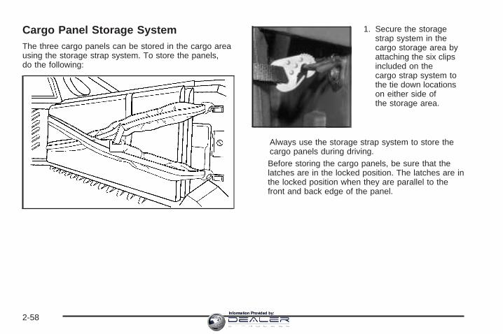
Cargo Panel Storage SystemThe three cargo panels can be stored in the cargo areausing the storage strap system. To store the panels,do the following:
1. Secure the storagestrap system in thecargo storage area byattaching the six clipsincluded on thecargo strap system tothe tie down locationson either side ofthe storage area.
Always use the storage strap system to store thecargo panels during driving.Before storing the cargo panels, be sure that thelatches are in the locked position. The latches are inthe locked position when they are parallel to thefront and back edge of the panel.
2-58Information Provided by:
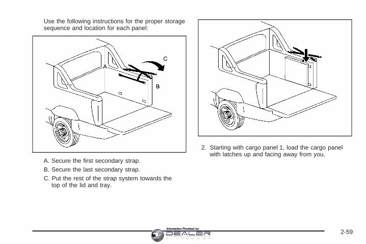
Use the following instructions for the proper storagesequence and location for each panel:
A. Secure the first secondary strap.B. Secure the last secondary strap.C. Put the rest of the strap system towards the
top of the lid and tray.
2. Starting with cargo panel 1, load the cargo panelwith latches up and facing away from you.
2-59Information Provided by:

3. Store cargo panel 2 by loading the cargo panel withlatches down and facing toward you.
4. Store cargo panel 3 by loading the cargo panel withlatches up and facing away from you.
2-60Information Provided by:

5. Move the rest of the strap system inside thecargo box, covering the three cargo covers (A).Fasten the four strap clips (B).
6. Tighten all straps by pulling on the free end ofeach strap.
2-61Information Provided by:
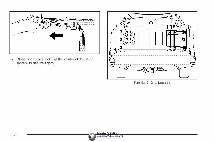
7. Close both cross locks at the center of the strapsystem to secure tightly.
Panels 3, 2, 1 Loaded
2-62Information Provided by:
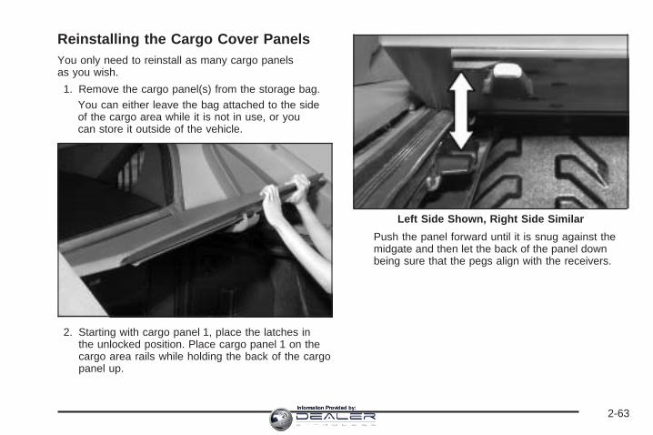
Reinstalling the Cargo Cover PanelsYou only need to reinstall as many cargo panelsas you wish.
1. Remove the cargo panel(s) from the storage bag.You can either leave the bag attached to the sideof the cargo area while it is not in use, or youcan store it outside of the vehicle.
2. Starting with cargo panel 1, place the latches inthe unlocked position. Place cargo panel 1 on thecargo area rails while holding the back of the cargopanel up.
Push the panel forward until it is snug against themidgate and then let the back of the panel downbeing sure that the pegs align with the receivers.
Left Side Shown, Right Side Similar
2-63Information Provided by:

3. Push both left latches away from you to lock thelatches (remember that there are two latches oneach side for panel 1). You should hear a clickwhen each latch locks correctly. Lock the remainingtwo right latches on panel 1.For any cargo cover panel you must lock the leftlatch in place before you can lock the right latch.If you do not follow this exactly, the cargo coverpanels may not lock in place correctly.
4. Install cargo cover 2 next. Place the latches in theunlocked position. Place the cargo cover panel onthe cargo area rails while holding the back ofthe cargo panel up.
Push the panel forward until it is snug against theother panel and then let the back of the panel downbeing sure that the pegs align with the receivers.
Left Side Shown, Right Side Similar
2-64Information Provided by:
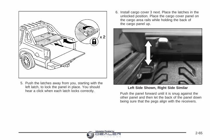
5. Push the latches away from you, starting with theleft latch, to lock the panel in place. You shouldhear a click when each latch locks correctly.
6. Install cargo cover 3 next. Place the latches in theunlocked position. Place the cargo cover panel onthe cargo area rails while holding the back ofthe cargo panel up.
Push the panel forward until it is snug against theother panel and then let the back of the panel downbeing sure that the pegs align with the receivers.
Left Side Shown, Right Side Similar
2-65Information Provided by:
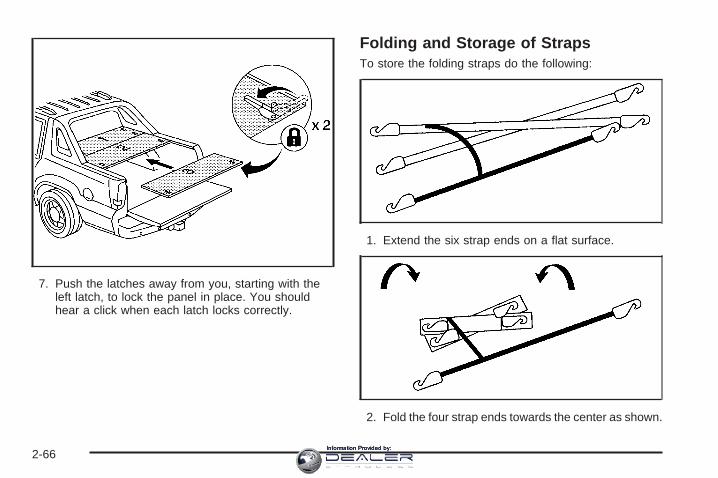
7. Push the latches away from you, starting with theleft latch, to lock the panel in place. You shouldhear a click when each latch locks correctly.
Folding and Storage of StrapsTo store the folding straps do the following:
1. Extend the six strap ends on a flat surface.
2. Fold the four strap ends towards the center as shown.
2-66Information Provided by:

3. Take the short strap and surround the foldedwebbing, forming a package.
4. Take the long strap and wrap it around the packageFinally, attach the hooks to the webbing.
Cargo Tie Downs
There are cargo tie downs in the rear cargo area thatyou can use to strap cargo in. The tie downs arealso used to secure the cargo cover panel storage bag.For more information see “Cargo Cover Panels”earlier in this section.
2-67Information Provided by:
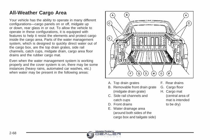
All-Weather Cargo AreaYour vehicle has the ability to operate in many differentconfigurations—cargo panels on or off, midgate upor down, rear glass in or out. To allow the vehicle tooperate in these configurations, it is equipped withfeatures to help it resist the elements and protect cargoinside the cargo area. Parts of the water managementsystem, which is designed to quickly direct water out ofthe cargo box, are the top drain grates, side railchannels, catch cups, midgate drain, cargo area floordrains and the rubber cargo mat.
Even when the water management system is workingproperly and the cover system is on, there may be someinstances (heavy rains, automated car washes, etc.)when water may be present in the following areas:
A. Top drain gratesB. Removable front drain grate
(midgate drain grate)C. Side rail channels and
catch cupsD. Front drainsE. Water drainage area
(around both sides of thecargo box and tailgate side)
F. Rear drainsG. Cargo floorH. Cargo mat
(central area ofmat is intendedto be dry)
2-68Information Provided by:

Maintenance and CleaningTo ensure that the water management system performsproperly, be sure that the midgate, tailgate and coversystem are fully closed and that each element of thewater management system is clean and not blockedwith debris. Follow the instructions given next in thissection for the proper procedures on cleaning each itemof the water management system.
Top Drain Grates – Removal andCleaning
The top drain grates are located near the rear glass onboth sides of the vehicle. You may need to clean thegrates and drains if there seems to be blockage.
To remove each drain grate, do the following:1. Remove the cargo panels. See Cargo Cover Panels
on page 2-55 for more information.
2. Grasp the edges of the grate and pull it out fromthe vehicle. Flush the drain with clean water.
2-69Information Provided by:
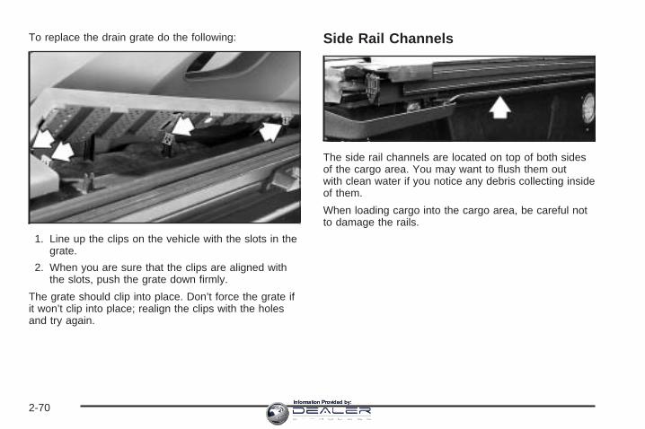
To replace the drain grate do the following:
1. Line up the clips on the vehicle with the slots in thegrate.
2. When you are sure that the clips are aligned withthe slots, push the grate down firmly.
The grate should clip into place. Don’t force the grate ifit won’t clip into place; realign the clips with the holesand try again.
Side Rail Channels
The side rail channels are located on top of both sidesof the cargo area. You may want to flush them outwith clean water if you notice any debris collecting insideof them.
When loading cargo into the cargo area, be careful notto damage the rails.
2-70Information Provided by:

Midgate Drain Grate Removal andCleaning
The midgate drain grate is located near the base of themidgate in the cargo area. You will find a removabledrain grate covering the drain.
After hauling dirt, wood chips, pebbles etc. you willneed to flush the midgate drain with water. But firstyou will have to remove the drain grate by usingthe following steps:
1. Lower the midgate. See Midgate® on page 2-11for more information.
2. Pull up on the rear side of the drain grate.
3. Tilt the drain grate away from you and pull itstraight out.
Reverse the procedure to reinstall the drain grate.
2-71Information Provided by:

Cargo Area Floor Drains
Your vehicle also has four cargo-area floor drainslocated under the cargo mat near the sides of the cargoarea. These drains should be cleaned periodically toallow water to exit the cargo area.
The cargo mat has cutouts for the drains. You can flushthe drains through the cutouts, but if the cargo areais extremely dirty you can lift up the edges of the cargofloor mat or take the whole mat out and flush the drainswith water.
Top-Box Storage
Your vehicle is equipped with top-box storage units onboth side of the vehicle. The passenger side top boxcontains the tools you will need to change a flat tire.
Use the ignition/door key to unlock/lock it. Press the keycylinder button and swing the lid open. Turn on thecargo lamps, if equipped, if you need more light inside.See Exterior Cargo Lamps on page 3-17 for moreinformation.
2-72Information Provided by:
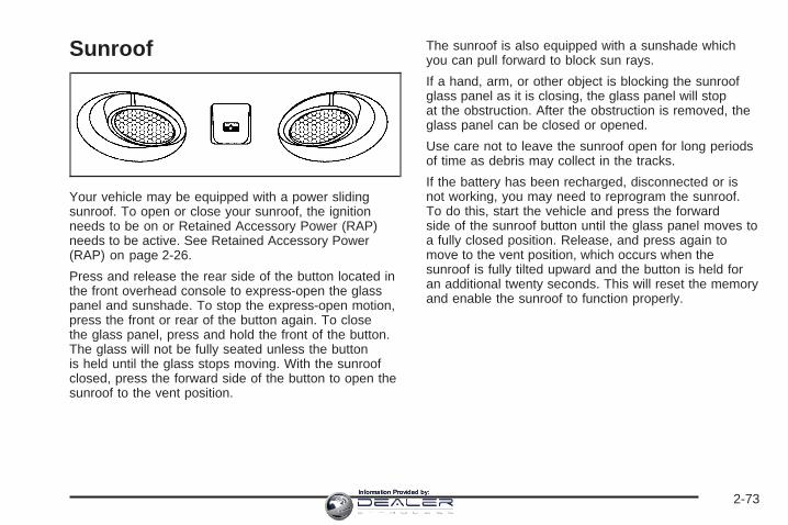
Sunroof
Your vehicle may be equipped with a power slidingsunroof. To open or close your sunroof, the ignitionneeds to be on or Retained Accessory Power (RAP)needs to be active. See Retained Accessory Power(RAP) on page 2-26.
Press and release the rear side of the button located inthe front overhead console to express-open the glasspanel and sunshade. To stop the express-open motion,press the front or rear of the button again. To closethe glass panel, press and hold the front of the button.The glass will not be fully seated unless the buttonis held until the glass stops moving. With the sunroofclosed, press the forward side of the button to open thesunroof to the vent position.
The sunroof is also equipped with a sunshade whichyou can pull forward to block sun rays.
If a hand, arm, or other object is blocking the sunroofglass panel as it is closing, the glass panel will stopat the obstruction. After the obstruction is removed, theglass panel can be closed or opened.
Use care not to leave the sunroof open for long periodsof time as debris may collect in the tracks.
If the battery has been recharged, disconnected or isnot working, you may need to reprogram the sunroof.To do this, start the vehicle and press the forwardside of the sunroof button until the glass panel moves toa fully closed position. Release, and press again tomove to the vent position, which occurs when thesunroof is fully tilted upward and the button is held foran additional twenty seconds. This will reset the memoryand enable the sunroof to function properly.
2-73Information Provided by:
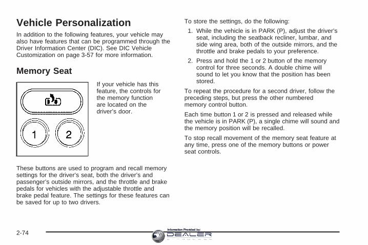
Vehicle PersonalizationIn addition to the following features, your vehicle mayalso have features that can be programmed through theDriver Information Center (DIC). See DIC VehicleCustomization on page 3-57 for more information.
Memory SeatIf your vehicle has thisfeature, the controls forthe memory functionare located on thedriver’s door.
These buttons are used to program and recall memorysettings for the driver’s seat, both the driver’s andpassenger’s outside mirrors, and the throttle and brakepedals for vehicles with the adjustable throttle andbrake pedal feature. The settings for these features canbe saved for up to two drivers.
To store the settings, do the following:
1. While the vehicle is in PARK (P), adjust the driver’sseat, including the seatback recliner, lumbar, andside wing area, both of the outside mirrors, and thethrottle and brake pedals to your preference.
2. Press and hold the 1 or 2 button of the memorycontrol for three seconds. A double chime willsound to let you know that the position has beenstored.
To repeat the procedure for a second driver, follow thepreceding steps, but press the other numberedmemory control button.
Each time button 1 or 2 is pressed and released whilethe vehicle is in PARK (P), a single chime will sound andthe memory position will be recalled.
To stop recall movement of the memory seat feature atany time, press one of the memory buttons or powerseat controls.
2-74Information Provided by:

Easy Exit SeatThe controls for this memory function are located onthe driver’s door.
B (Easy Exit Seat): This button is used to programand recall the desired driver’s seat position when exitingor entering the vehicle. The seat position can besaved for up to two drivers.
To store the seat exit position, do the following:
1. Press and release the 1 or 2 button. The seat willmove to the stored memory position.
2. Adjust the seat to the desired exit position.
3. Press and hold the exit button of the memorycontrol for three seconds. A double chime will soundto let you know that the position has been storedfor the selected button (1 or 2).
To repeat the procedure for a second driver,follow the preceding steps, but press the othernumbered memory control button.
To use the seat exit position, do one of the following:
• Press the exit button on the memory control.
• If this feature is activated in the Driver InformationCenter (DIC), removing the key from the ignitionwill move the seat to the exit position.
See “Easy Exit Seat” under DIC Vehicle Customizationon page 3-57 for more information on activating thisfeature in the DIC.
2-75Information Provided by:

✍ NOTES
2-76Information Provided by:
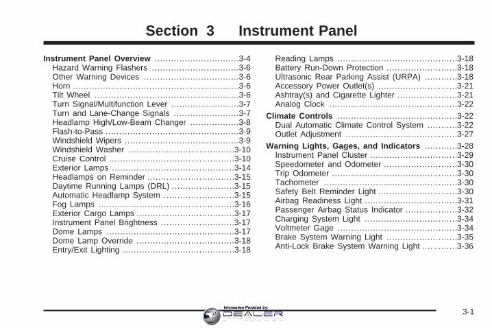
Instrument Panel Overview ...............................3-4Hazard Warning Flashers ................................3-6Other Warning Devices ...................................3-6Horn .............................................................3-6Tilt Wheel .....................................................3-6Turn Signal/Multifunction Lever .........................3-7Turn and Lane-Change Signals ........................3-7Headlamp High/Low-Beam Changer ..................3-8Flash-to-Pass .................................................3-9Windshield Wipers ..........................................3-9Windshield Washer .......................................3-10Cruise Control ..............................................3-10Exterior Lamps .............................................3-14Headlamps on Reminder ................................3-15Daytime Running Lamps (DRL) .......................3-15Automatic Headlamp System ..........................3-15Fog Lamps ..................................................3-16Exterior Cargo Lamps ....................................3-17Instrument Panel Brightness ...........................3-17Dome Lamps ...............................................3-17Dome Lamp Override ....................................3-18Entry/Exit Lighting .........................................3-18
Reading Lamps ............................................3-18Battery Run-Down Protection ..........................3-18Ultrasonic Rear Parking Assist (URPA) ............3-18Accessory Power Outlet(s) .............................3-21Ashtray(s) and Cigarette Lighter ......................3-21Analog Clock ...............................................3-22
Climate Controls ............................................3-22Dual Automatic Climate Control System ...........3-22Outlet Adjustment .........................................3-27
Warning Lights, Gages, and Indicators ............3-28Instrument Panel Cluster ................................3-29Speedometer and Odometer ...........................3-30Trip Odometer ..............................................3-30Tachometer .................................................3-30Safety Belt Reminder Light .............................3-30Airbag Readiness Light ..................................3-31Passenger Airbag Status Indicator ...................3-32Charging System Light ..................................3-34Voltmeter Gage ............................................3-34Brake System Warning Light ..........................3-35Anti-Lock Brake System Warning Light .............3-36
Section 3 Instrument Panel
3-1Information Provided by:
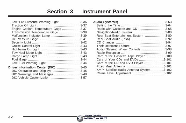
Low Tire Pressure Warning Light ....................3-36Traction Off Light ..........................................3-37Engine Coolant Temperature Gage ..................3-37Transmission Temperature Gage .....................3-38Malfunction Indicator Lamp .............................3-39Oil Pressure Gage ........................................3-41Security Light ...............................................3-42Cruise Control Light ......................................3-43Highbeam On Light .......................................3-43Tow/Haul Mode Light ....................................3-43Cargo Lamp Light .........................................3-43Fuel Gage ...................................................3-44Low Fuel Warning Light .................................3-44
Driver Information Center (DIC) .......................3-45DIC Operation and Displays ...........................3-45DIC Warnings and Messages .........................3-48DIC Vehicle Customization .............................3-57
Audio System(s) .............................................3-63Setting the Time ...........................................3-64Radio with Cassette and CD ..........................3-65Navigation/Radio System ...............................3-80Rear Seat Entertainment System ....................3-80Rear Seat Audio (RSA) .................................3-92CD Changer ................................................3-94Theft-Deterrent Feature ..................................3-97Audio Steering Wheel Controls .......................3-98Radio Reception ...........................................3-99Care of the Cassette Tape Player .................3-100Care of Your CDs and DVDs ........................3-101Care of the CD and DVD Player ...................3-101Fixed Mast Antenna ....................................3-101XM™ Satellite Radio Antenna System ............3-102Chime Level Adjustment ...............................3-102
Section 3 Instrument Panel
3-2Information Provided by:

✍ NOTES
3-3Information Provided by:

Instrument Panel Overview
3-4Information Provided by:
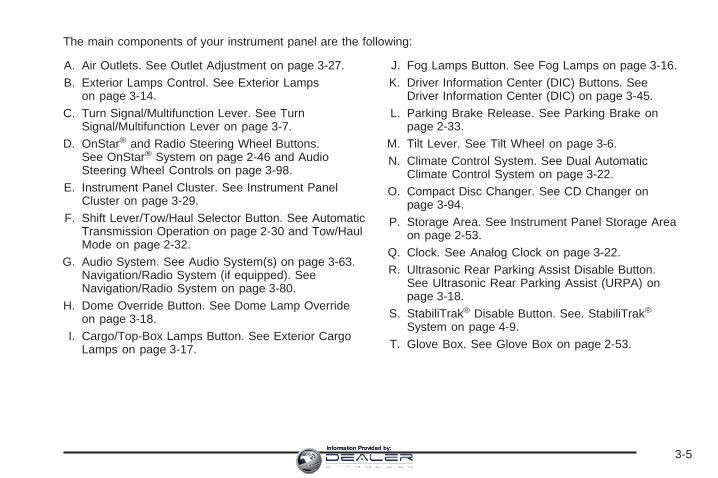
The main components of your instrument panel are the following:
A. Air Outlets. See Outlet Adjustment on page 3-27.B. Exterior Lamps Control. See Exterior Lamps
on page 3-14.C. Turn Signal/Multifunction Lever. See Turn
Signal/Multifunction Lever on page 3-7.D. OnStar® and Radio Steering Wheel Buttons.
See OnStar® System on page 2-46 and AudioSteering Wheel Controls on page 3-98.
E. Instrument Panel Cluster. See Instrument PanelCluster on page 3-29.
F. Shift Lever/Tow/Haul Selector Button. See AutomaticTransmission Operation on page 2-30 and Tow/HaulMode on page 2-32.
G. Audio System. See Audio System(s) on page 3-63.Navigation/Radio System (if equipped). SeeNavigation/Radio System on page 3-80.
H. Dome Override Button. See Dome Lamp Overrideon page 3-18.
I. Cargo/Top-Box Lamps Button. See Exterior CargoLamps on page 3-17.
J. Fog Lamps Button. See Fog Lamps on page 3-16.K. Driver Information Center (DIC) Buttons. See
Driver Information Center (DIC) on page 3-45.L. Parking Brake Release. See Parking Brake on
page 2-33.M. Tilt Lever. See Tilt Wheel on page 3-6.N. Climate Control System. See Dual Automatic
Climate Control System on page 3-22.O. Compact Disc Changer. See CD Changer on
page 3-94.P. Storage Area. See Instrument Panel Storage Area
on page 2-53.Q. Clock. See Analog Clock on page 3-22.R. Ultrasonic Rear Parking Assist Disable Button.
See Ultrasonic Rear Parking Assist (URPA) onpage 3-18.
S. StabiliTrak® Disable Button. See. StabiliTrak®
System on page 4-9.T. Glove Box. See Glove Box on page 2-53.
3-5Information Provided by:

Hazard Warning FlashersYour hazard warning flashers let you warn others. Theyalso let police know you have a problem. Your frontand rear turn signal lamps will flash on and off.
The hazard warningflasher button islocated on top of thesteering column.
Your hazard warning flashers work no matter whatposition your key is in, and even if the key is not inthe ignition.Press the button to make the front and rear turn signallamps flash on and off. Press the button again toturn the flashers off.When the hazard warning flashers are on, your turnsignals will not work.
Other Warning DevicesIf you carry reflective triangles, you can set them up atthe side of the road about 300 feet (100 m) behindyour vehicle.
HornTo sound the horn, press the center pad on thesteering wheel.
Tilt WheelThe tilt steering wheel allows you to adjust the steeringwheel before you drive. You can raise it to the highestlevel to give your legs more room when you enterand exit the vehicle.
The tilt lever is located on the driver’s side of thesteering column under the turn signal lever.
To tilt the wheel, hold the steering wheel and pull thelever. Move the steering wheel to a comfortablelevel, then release the lever to lock the wheel in place.
3-6Information Provided by:

Turn Signal/Multifunction Lever
The lever on the left side of the steering columnincludes the following:
• G Turn and Lane Change Signals. Turn andLane-Change Signals on page 3-7.
• 53 Headlamp High/Low-Beam Changer.Headlamp High/Low-Beam Changer on page 3-8.
• Flash-to-Pass Feature. See Flash-to-Pass onpage 3-9.
• N Windshield Wipers. See Windshield Wipers onpage 3-9.
• L Windshield Washer. See Windshield Washeron page 3-10.
• I Cruise Control. Cruise Control on page 3-10.
For information on the exterior lamps, see ExteriorLamps on page 3-14 later in this section.
Turn and Lane-Change SignalsThe turn signal has two upward (for right) andtwo downward (for left) positions. These positionsallow you to signal a turn or a lane change.
To signal a turn, move the lever all the way up ordown. When the turn is finished, the lever will returnautomatically.
To signal a lane change, just raise or lower the leveruntil the arrow starts to flash. Hold it there until youcomplete your lane change. The lever will return by itselfwhen you release it.
3-7Information Provided by:
An arrow on the instrumentpanel cluster will flash inthe direction of theturn or lane change.
As you signal a turn or a lane change, if the arrows flashmore quickly than normal, a signal bulb may be burnedout and other drivers won’t see your turn signal.
If a bulb is burned out, replace it to help avoid anaccident. If the arrows don’t go on at all when you signala turn, check for burned-out bulbs and a blown fuse.See Instrument Panel Fuse Block on page 5-110and Underhood Fuse Block on page 5-113.
Turn Signal On ChimeIf your turn signal is left on for more than 3/4 of a mile(1.2 km), a chime will sound at each flash of the turnsignal and the message TURN SIGNAL ON will alsoappear in the DIC. See DIC Warnings and Messages onpage 3-48. To turn the chime and message off, move theturn signal lever to the off position.
Headlamp High/Low-Beam Changer
53(Headlamp High/Low Beam Changer): Tochange the headlamps from low to high beam, push thelever toward the instrument panel. To return tolow-beam headlamps, pull the multifunction lever towardyou. Then release it.
When the high beams areon, this indicator light onthe instrument panelcluster will also be on.
3-8Information Provided by:

Flash-to-PassThis feature lets you use your high-beam headlampsto signal a driver in front of you that you want topass. It works even if your headlamps are in theautomatic position.
To use it, pull the turn signal lever toward you, thenrelease it.
If your headlamps are in the automatic position or onlow beam, your high-beam headlamps will turn on.They’ll stay on as long as you hold the lever toward you.The high-beam indicator on the instrument panelcluster will come on. Release the lever to return tonormal operation.
Windshield WipersYou control the windshield wipers by turning the bandwith the wiper symbol on it.
8(Mist): For a single wiping cycle, turn the band tomist. Hold it there until the wipers start. Then let go.The wipers will stop after one wipe. If you wantmore wipes, hold the band on mist longer.
N(Delay): You can set the wiper speed for a long orshort delay between wipes. This can be very usefulin light rain or snow. Turn the band to choose the delaytime. The closer to the top of the lever, the shorterthe delay.
6 (Low Speed): For steady wiping at low speed,turn the band away from you to the first solid band pastthe delay settings.
1 (High Speed): For high-speed wiping, turn theband further, to the second solid band past thedelay settings.
9(Off): To stop the wipers, move the band to off.
Be sure to clear ice and snow from the wiper bladesbefore using them. If they’re frozen to the windshield,carefully loosen or thaw them. If your blades do becomeworn or damaged, get new blades or blade inserts.
3-9Information Provided by:

Windshield Washer
L(Washer Fluid): There is a paddle marked with thewindshield washer symbol at the top of the multifunctionlever. To spray washer fluid on the windshield, pushthe paddle. The wipers will clear the window and theneither stop or return to your preset speed.
{CAUTION:
In freezing weather, do not use your washeruntil the windshield is warmed. Otherwise thewasher fluid can form ice on the windshield,blocking your vision.
Cruise Control
9(Off): This positionturns the system off.
R(On): This position activates the system.
+ (Resume/Accelerate): Push the lever to this symbolto make the vehicle accelerate or resume to apreviously set speed.
r SET I (Set): Press this button to set the speed.
With cruise control, you can maintain a speed ofabout 25 mph (40 km/h) or more without keeping yourfoot on the accelerator. This can really help on long trips.Cruise control does not work at speeds below about25 mph (40 km/h).
3-10Information Provided by:

If you apply your brakes, the cruise control will shut off.
{CAUTION:
Cruise control can be dangerous where youcannot drive safely at a steady speed. So, donot use your cruise control on winding roadsor in heavy traffic.
Cruise control can be dangerous on slipperyroads. On such roads, fast changes in tiretraction can cause needless wheel spinning,and you could lose control. Do not use cruisecontrol on slippery roads.
Setting Cruise Control
{CAUTION:
If you leave your cruise control on when youare not using cruise, you might hit a buttonand go into cruise when you do not want to.You could be startled and even lose control.Keep the cruise control switch off until youwant to use cruise control.
1. Move the cruise control switch to on.
2. Get up to the speed you want.
3. Press in the set button at the end of the lever andrelease it.
4. Take your foot off the accelerator pedal.
The cruise light on theinstrument panel willilluminate when the cruisecontrol is engaged.
3-11Information Provided by:

Resuming a Set SpeedSuppose you set your cruise control at a desiredspeed and then you apply the brake. This, of course,disengages the cruise control. But you do not needto reset it.
Once you’re going about 25 mph (40 km/h) or more,you can move the cruise control switch briefly from on toresume/accelerate.
You will go right back up to your chosen speed andstay there.
If you hold the switch at resume/accelerate the vehiclewill keep going faster until you release the switch orapply the brake. So unless you want to go faster, do nothold the switch at resume/accelerate.
Increasing Speed While Using CruiseControlThere are two ways to go to a higher speed:
• Use the accelerator pedal to get to the higherspeed. Press the set button at the end of the lever,then release the button and the acceleratorpedal. You will now cruise at the higher speed.If the accelerator pedal is held longer than60 seconds, cruise control will turn off.
• Move the cruise switch from on toresume/accelerate. Hold it there until you get up tothe speed you want, and then release the switch.To increase your speed in very small amounts,move the switch briefly to resume/accelerate.Each time you do this, your vehicle will go about1 mph (1.6 km/h) faster.
3-12Information Provided by:
Reducing Speed While Using CruiseControl• Press in the button at the end of the lever until you
reach the lower speed you want, then release it.
• To slow down in very small amounts, briefly pressthe set button. Each time you do this, you will goabout 1 mph (1.6 km/h) slower.
Passing Another Vehicle While UsingCruise ControlUse the accelerator pedal to increase your speed.When you take your foot off the pedal, your vehicle willslow down to the cruise control speed you set earlier.
Using Cruise Control on HillsHow well your cruise control will work on hills dependsupon your speed, load and the steepness of thehills. When going up steep hills, you may want to stepon the accelerator pedal to maintain your speed.When going downhill, you may have to brake or shift toa lower gear to keep your speed down. Of course,applying the brake takes you out of cruise control.Many drivers find this to be too much trouble and do notuse cruise control on steep hills.
Ending Cruise ControlTo turn off the cruise control, do one of the following:
• Step lightly on the brake pedal,
• move the cruise control switch to off, or
• shift the transmission to NEUTRAL (N).
• If your vehicle has the StabiliTrak® feature, cruisecontrol will turn off if road conditions causeStabiliTrak® to activate.
• If the accelerator pedal is held longer than60 seconds, cruise control will turn off.
The cruise control will turn off automatically if thetraction control system or StabiliTrak® system activate,if your vehicle is equipped with either feature.
Erasing Speed MemoryWhen you turn off the cruise control or the ignition,your cruise control set speed memory is erased.
3-13Information Provided by:

Exterior Lamps
The control on the driver’s side of your instrument paneloperates the exterior lamps.
The exterior lamp control has four positions:
9(Off): Turn the knob to this position and release it toturn off all exterior lamps including the DRL. To turn anylamps back on when in the off mode, turn the knob to thedesired lamp mode. To return to the AUTO mode, turnthe knob to the off position and release it. The off orAUTO mode will also cancel and the lamps will return tothe AUTO when the vehicle is turned off. This mode is notavailable for vehicles sold in Canada.
AUTO: Turn the control to this position to put thesystem into automatic headlamp mode. The DaytimeRunning Lamps (DRL) will also be activated if it is lightenough outside.
;(Parking Lamps): Turn the control to this position toturn on the parking lamps, together with the following:
• Sidemarker Lamps
• Taillamps
• License Plate Lamps
• Instrument Panel Lights
2(Headlamps): Turn the control to this position toturn on the headlamps, together with the previouslylisted lamps and lights.
When the vehicle is turned off and the headlamps are inAUTO, the headlamps may automatically remain onfor a set time. You can change this delay time using theDIC. See Driver Information Center (DIC) on page 3-45.
You can switch your headlamps from low to high-beamby pushing the turn signal/multifunction lever towardthe instrument panel.
3-14Information Provided by:
Headlamps on ReminderIf a door is open, a reminder chime will sound when yourheadlamps or parking lamps are manually turned on andyour key is out of the ignition. To turn off the chime, turnthe headlamp switch to off or AUTO and then back on. Inthe AUTO mode, the headlamps turn off once the ignitionis in LOCK or may remain on until the headlamp delayends (if enabled in the DIC).
Daytime Running Lamps (DRL)Daytime Running Lamps (DRL) can make it easier forothers to see the front of your vehicle during theday. DRL can be helpful in many different drivingconditions, but they can be especially helpful in the shortperiods after dawn and before sunset. Fully functionaldaytime running lamps are required on all vehiclesfirst sold in Canada.
The DRL system will come on when the followingconditions are met:
• The ignition is on,
• the exterior lamps control is in AUTO,
• the transmission is not in PARK (P), and
• the light sensor determines it is daytime.
When the DRL are on, only your DRL lamps will be on.The taillamps, sidemarker and other lamps won’t beon. The instrument panel won’t be lit up either.
When it begins to get dark, the automatic headlampsystem will switch from DRL to the headlamps.
As with any vehicle, you should turn on the regularheadlamp system when you need it.
Automatic Headlamp SystemWhen it is dark enough outside and the headlampswitch is in AUTO, your automatic headlamp system willturn on your headlamps at the normal brightnessalong with other lamps such as the taillamps,sidemarker, parking lamps, roof marker lamps and theinstrument panel lights. The radio lights will also be dim.
To turn off the automatic headlamp system, turn theexterior lamps switch to the off position and then release.Turning off the automatic headlamp system with theheadlamp switch is not available for vehicles first sold inCanada. For vehicles first sold in Canada, you can turnoff the automatic headlamp system when parked at nightby applying the parking brake before starting yourvehicle. The headlamps will remain off once the vehicle isstarted for as long as you are parked. If you release theparking brake, the lights will turn on. If the parking brakeis not released before you begin to drive, the exteriorlamps will turn on above 2 mph (3.2 km/h).
3-15Information Provided by:

Your vehicle has a light sensor located on the top of theinstrument panel. Be sure it is not covered, or thesystem will be on whenever the ignition is on.
The system may also turn on your headlamps whendriving through a parking garage, heavy overcastweather or a tunnel. This is normal.
There is a delay in the transition between the daytimeand nighttime operation of the Daytime RunningLamps (DRL) and the automatic headlamp systems sothat driving under bridges or bright overhead streetlights does not affect the system. The DRL andautomatic headlamp system will only be affected whenthe light sensor sees a change in lighting lastinglonger than the delay.
If you start your vehicle in a dark garage, the automaticheadlamp system will come on immediately. Onceyou leave the garage, it will take approximatelyone minute for the automatic headlamp system tochange to DRL if it is light outside. During that delay,your instrument panel cluster may not be as brightas usual. Make sure your instrument panel brightnesscontrol is in the full bright position. See Instrument PanelBrightness on page 3-17.
Fog LampsIf your vehicle has fog lamps you can use them forbetter vision in foggy or misty conditions. Your parkinglamps and/or low-beam headlamps must be on foryour fog lamps to work.
The fog lamp button islocated on the left side ofyour instrument panel.
Press the button to turn the fog lamps on while theheadlamps or parking lamps are on. Press the buttonagain to turn them off. An indicator light will glownear the button when the fog lamps are on.
Remember, fog lamps alone will not give off as muchlight as your headlamps. Never use your fog lampsin the dark without turning on the headlamps.
3-16Information Provided by:

The fog lamps will go off whenever your high-beamheadlamps come on. When the high beams go off, thefog lamps will come on again.
The fog lamps will be cancelled after the ignition isturned off. If you still want to use the fog lamps afteryou restart the vehicle, you will need to press thefog lamp button again.
Some localities have laws that require the headlamps tobe on along with the fog lamps.
Exterior Cargo LampsYou can use the cargo lamp if you need more light inthe cargo area of your vehicle or in the top-box storageunits. Some vehicles will only have a cargo lamp inthe passenger side top box.
Press the button, with thissymbol to turn the cargolamps on or off.
The cargo lamps symbol light will come on in theinstrument panel cluster when the cargo lamps are onand the ignition key is turned to run.
Instrument Panel BrightnessThe thumbwheel for this feature is located next to theexterior lamps control.
D (Instrument Panel Lights): Turn the thumbwheelup or down to brighten or dim the instrument panellights and the radio display. This will only work ifthe headlamps or parking lamps are on.
To turn on the dome lamps, with the vehicle doorsclosed, turn the thumbwheel all the way up.
Dome LampsThe dome lamps will come on when you open a door orthe midgate, if equipped, and will turn off when alldoors or midgate are closed.
You can also turn the dome lamps on by turning thethumbwheel, located next to the exterior lamp control,all the way up. In this position, the dome lamps willremain on whether a door is opened or closed.
3-17Information Provided by:

Dome Lamp OverrideE (Dome Lamp Override): You can use the domeoverride button, located below the exterior lamps control,to set the dome lamps to come on automatically when adoor is opened, or to remain off. To turn the lamps off,press the button into the in position. With the button inthis position, the dome lamps will remain off when thedoors are open. To return the lamps to automaticoperation, press the button again and return it to the outposition. With the button in this position, the dome lampswill come on when you open a door.
Entry/Exit LightingYour vehicle is equipped with an illuminatedentry/exit feature.
When a door is opened or the key is removed from theignition, the dome lamps will come on if the domeoverride button is in the out position.
Reading LampsIf your vehicle has reading lamps, press the buttonlocated next to the lamp to turn it on or off. The lamps canbe adjusted to point in the direction you want.Your vehicle may also have reading lamps in otherlocations. To turn on or off, press the button located nextto the lamp. The lamps cannot be adjusted.
Battery Run-Down ProtectionThis feature shuts off the dome lamps if they are left onfor more than 10 minutes when the ignition is inLOCK. This will keep your battery from running down.
Ultrasonic Rear ParkingAssist (URPA)The Ultrasonic Rear Parking Assist (URPA) system isdesigned to help you park, while the vehicle is inREVERSE (R). It operates only at very low speeds, lessthan 3 mph (5 km/h). URPA can help make parkingeasier and to help you avoid colliding with objects suchas parked vehicles. The URPA system can detectobjects up to 5 feet (1.5 m) behind the vehicle, andtell you how close these objects are from yourrear bumper.
Your vehicle’s URPA operates when the shift lever ismoved into REVERSE (R) and the vehicle speed is lessthan 3 mph (5 km/h). Four ultrasonic sensors locatedat the rear bumper are used to detect the distance tothe object.
3-18Information Provided by:

The URPA display islocated inside the vehicle,near the rear window.It has three color-codedlights used to providedistance and systeminformation to the driver.
URPA can be turned off bypressing the rear park aiddisable button locatednear the climate controlsystem and radio. You willnot see any lights onthe rear display if URPA isturned off.
{CAUTION:
Even with the Ultrasonic Rear Park Assistsystem, the driver must check carefully beforebacking up. The system does not operate abovetypical backing speeds of 3 mph (5 km/h) whileparking. And, the system does not detectobjects that are more than 5 feet (1.5 meters)behind the vehicle.
So, unless you check carefully behind youbefore and when you back up, you could strikechildren, pedestrians, bicyclists or pets behindyou, and they could be injured or killed.
Whether or not you are using rear park assist,always check carefully behind your vehiclebefore you back up and then watch closely asyou do.
3-19Information Provided by:

How the System WorksUnless disabled, the URPA will turn on automaticallywhen the shift lever is moved into REVERSE (R). Whenthe system turns on, the three lights on the displaywill illuminate for one and a half seconds to let you knowthat the system is working. If your vehicle is moving inREVERSE (R) at a speed greater than 3 mph (5 km/h),the red light will flash to remind you that the systemdoes not work at a speed greater than 3 mph (5 km/h).
If an object is detected at a REVERSE (R) speed ofless than 3 mph (5 km/h), one of the following will occur:
A chime will sound the first time an object is detectedbetween 20 inches (0.5 m) and 5 feet (1.5 m) away.
Description English Metricamber light 5 ft. 1.5 m
amber/amber lights 40 in. 1.0 mamber/amber/red lights &
continuous chime 20 in. 0.5 m
amber/amber/red lightsflashing &
continuous chime1 ft 0.3 m
URPA cannot detect objects that are above tailgate level.In order for the rear sensors to recognize an object, itmust be within detection range behind the vehicle.
Notice: If you use URPA while the tailgate islowered, it may not detect an object behind yourvehicle, and you might back into the object anddamage your vehicle. Always verify the tailgate isclosed when using URPA or turn off URPA whendriving with the tailgate lowered.
When the System Does Not Seem toWork ProperlyThe light may flash red when the vehicle is inREVERSE (R) if the ultrasonic sensors are not keptclean. So be sure to keep your rear bumper free of mud,dirt, snow, ice and slush. Other conditions that mayaffect system performance include things like thevibrations from a jackhammer or the compression ofair brakes on a very large truck. If after cleaningthe rear bumper and then driving forward at least15 mph (25 km/h), the display continues to flash red,see your dealer.
If a trailer was attached to your vehicle, or a bicycle oran object was on the back of, or hanging out of yourcargo area during your last drive cycle, the lightmay also flash red. The light will continue to flashwhenever in REVERSE (R) until your vehicle is drivenforward at least 15 mph (25 km/h) without anyobstructions behind the vehicle.
For cleaning instructions, see Washing Your Vehicle onpage 5-103.
3-20Information Provided by:

Accessory Power Outlet(s)Your vehicle is equipped with many accessorypower outlets.
One outlet is located in the center console. Press thebutton on the side of the console door to accessthe outlet.
There may also be an accessory power outlet locatedon the back of the center console above the cupholder.
Do not try to put the cigarette lighter in any of theaccessory outlets.
Notice: Adding any electrical equipment to yourvehicle may damage it or keep other componentsfrom working as they should. The repairs would notbe covered by your warranty. Do not use equipmentexceeding maximum amperage rating. Checkwith your dealer before adding electrical equipment.
Certain power accessory plugs may not be compatiblewith the accessory power outlets and could resultin blown vehicle or adapter fuses. If you experience aproblem, see your dealer for additional informationon the accessory power plugs.
Notice: Improper use of the power outlet can causedamage not covered by your warranty. Do nothang any type of accessory or accessory bracketfrom the plug because the power outlets aredesigned for accessory power plugs only.
Ashtray(s) and Cigarette LighterThe front ashtray and lighter are located in the centerconsole near the cupholders, if equipped. Press onthe access door to open it and use the ashtrayand lighter.
Notice: If you put papers, pins, or other flammableitems in the ashtray, hot cigarettes or othersmoking materials could ignite them and possiblydamage your vehicle. Never put flammable items inthe ashtray.
To remove the ashtray, pull it from the center console.Slide it back in and push down to be sure it is secure.
To use the cigarette lighter, push it in all the way, andlet go. When it’s ready, it will pop back out by itself.
Notice: Holding a cigarette lighter in while itis heating will not allow the lighter to back awayfrom the heating element when it is hot. Damagefrom overheating may occur to the lighter or heatingelement, or a fuse could be blown. Do not hold acigarette lighter in while it is heating.
3-21Information Provided by:
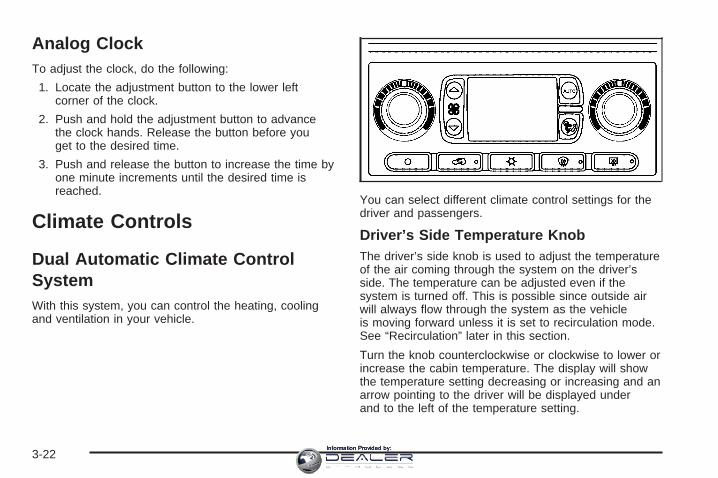
Analog ClockTo adjust the clock, do the following:
1. Locate the adjustment button to the lower leftcorner of the clock.
2. Push and hold the adjustment button to advancethe clock hands. Release the button before youget to the desired time.
3. Push and release the button to increase the time byone minute increments until the desired time isreached.
Climate Controls
Dual Automatic Climate ControlSystemWith this system, you can control the heating, coolingand ventilation in your vehicle.
You can select different climate control settings for thedriver and passengers.
Driver’s Side Temperature KnobThe driver’s side knob is used to adjust the temperatureof the air coming through the system on the driver’sside. The temperature can be adjusted even if thesystem is turned off. This is possible since outside airwill always flow through the system as the vehicleis moving forward unless it is set to recirculation mode.See “Recirculation” later in this section.
Turn the knob counterclockwise or clockwise to lower orincrease the cabin temperature. The display will showthe temperature setting decreasing or increasing and anarrow pointing to the driver will be displayed underand to the left of the temperature setting.
3-22Information Provided by:

Passenger’s Side Temperature KnobThe passenger’s side knob can be used to change thetemperature of the air coming through the systemon the passenger’s side of the vehicle. The temperaturecan be adjusted even if the system is turned off. Thisis possible since outside air will always flow through thesystem as the vehicle is moving forward unless it isset to recirculation mode. See “Recirculation” later inthis section.
Turn the knob counterclockwise or clockwise to lower orincrease the cabin temperature. The display will showthe temperature setting decreasing or increasing and anarrow pointing to the passenger will be displayedunder and to the right of the temperature setting.
The passenger’s temperature setting can be set tomatch the driver’s temperature setting by pressing andholding the AUTO button for four seconds. Both thedriver and passenger arrows will be displayed.
Automatic Operation
AUTO (Automatic): When automatic operation isactive the system will control the inside temperature,the air delivery, and the fan speed.
Use the steps below to place the entire system inautomatic mode:
1. Press the AUTO button.When AUTO is selected, the display will change toshow the current driver’s set temperature, deliverymode and fan speed. Press the AUTO button againwithin five seconds to display the passenger’s settemperature.If the driver’s and passenger’s temperature settingsare the same when AUTO is pressed, thetemperature setting and both arrows will bedisplayed for five seconds along with the automaticair delivery mode and fan speed. After thefive-second update, the display will change to showthe temperature setting, both arrows and AUTO.If the driver’s and passenger’s temperature settingsare not the same, the opposite side temperaturesetting will be displayed for an additionalfive seconds. To make the passenger’s temperaturethe same as the driver’s press and hold theAUTO button for about four seconds.When auto is selected, the air conditioningoperation and air inlet will be automaticallycontrolled. The air conditioning compressor willrun when the outside temperature is over about40°F (4°C). The air inlet will normally be set tooutside air. If it’s hot outside, the air inlet mayautomatically switch to recirculate inside air to helpquickly cool down your vehicle. The light on thebutton will illuminate in recirculation.
3-23Information Provided by:
2. Set the driver’s and passenger’s temperature.To find your comfort setting, start with a 74°F (23°C)temperature setting and allow about 20 minutesfor the system to regulate. Turn the driver’s orpassenger’s side temperature knob to adjust thetemperature setting as necessary. If you choose thetemperature setting of 60°F (15°C) the systemwill remain at the maximum cooling setting. If youchoose the temperature setting of 90°F (32°C)the system will remain at the maximum heat setting.Choosing either maximum setting will not causethe vehicle to heat or cool any faster.Be careful not to cover the sensor located on thetop of the instrument panel near the windshield.This sensor regulates air temperature based onsun load, and also turns on your headlamps.To avoid blowing cold air in cold weather, thesystem will delay turning on the fan until warm air isavailable. The length of delay depends on theengine coolant temperature. Pressing the fan switchwill override this delay and change the fan to aselected speed.
9(Off): Press this button to turn off the entire climatecontrol system. Outside air will still enter the vehicle,and will be directed to the floor. This direction canbe changed by pressing the mode button. Thetemperature can also be adjusted using eithertemperature knob. Press the up or down arrows on thefan switch, the defrost button, the AUTO button, orthe air conditioning button to turn the system on whenit is off.
Manual OperationYou may manually adjust the air delivery mode orfan speed.
w9x (Fan): The switch with the fan symbol allowsyou to manually adjust the fan speed. Press the uparrow to increase fan speed and the down arrowto decrease fan speed.
Pressing this button when the system is off will turn thesystem on.
3-24Information Provided by:

C (Mode): Press this button to manually changethe direction of the airflow in your vehicle. Repeatedlypress the button until the desired mode appears onthe display.
If you press the mode button to select an air deliverymode, the display will change to show you the selectedair mode delivery. The display will then show thecurrent status of the system. When the system is turnedoff, the display will go blank after displaying thecurrent status of the system.
H (Panel): This setting will deliver air to theinstrument panel outlets.
)(Bi-Level): This setting will deliver warmer air to thefloor and cooler air to the instrument panel outlets.
6 (Floor): This setting will deliver air to thefloor outlets.
- (Defog): See “Defogging and Defrosting” later inthis section.
@(Recirculation): Press this button to limit theamount of outside air entering your vehicle. The light onthe recirculation button will glow. This is helpful when youare trying to limit odors entering your vehicle and formaximum air conditioning performance in hot weather.Press this button again to allow outside air to enter thevehicle. The light on the recirculation button will go off.
Pressing this button also cancels the auto recirculationfeature. To resume the auto recirculation function, pressthe AUTO button. Each time the vehicle is started, thesystem will revert to the auto recirculation function.
If you select recirculation while in defrost, defog or floor,the light in the button will flash and then go out to let youknow that this is not allowed. This is normal and helps toprevent fogging.
When the weather is cool or damp, operating the systemin recirculation for extended periods of time may causefogging of the vehicle’s windows. To clear the fog, selecteither defog or front defrost.
You may also notice that the A/C compressor will runwhile in recirculation mode. This is normal and helps toprevent fogging.
3-25Information Provided by:

#(Air Conditioning): Press this button to turn the airconditioning (A/C) compressor on and off. Thesnowflake symbol will appear on the display when theA/C is on and will turn off when the air conditioning is off.
Pressing this button when the outside temperature istoo cool for air conditioning to be effective will make thesnowflake symbol flash three times and then turn offto let you know that the air conditioning mode isnot available. If the air conditioning is on and the outsidetemperature drops below a temperature which is toocool for air conditioning to be effective, the snowflakesymbol will turn off to let you know that the airconditioning mode has been canceled.
When air conditioning is selected or in AUTO mode, thesystem will run the air conditioning automatically to cooland dehumidify the air entering the vehicle. If you selectA/C off while in front defrost, defog or recirculation, theA/C snowflake symbol will turn off, but the A/Ccompressor will still run to help prevent fogging.
On hot days, open the windows long enough to let hotinside air escape. This reduces the time it takes foryour vehicle to cool down. Then keep your windowsclosed for the air conditioner to work its best.
On cool, but sunny days while using manual operationof the automatic system, use bi-level to deliver warmair to the floor and cooler air to the instrumentpanel outlets. To warm or cool the air delivered, turn thetemperature knob to the desired setting.
In AUTO mode the system will cool and dehumidify theair inside the vehicle. Also while in AUTO mode, thesystem will maximize its performance by usingrecirculation as necessary.
9(Off): Press this button to turn off the entire climatecontrol system. Outside air will still enter the vehicle, andwill be directed to the floor. This direction can be changedby pressing the mode button. The temperature can alsobe adjusted using either temperature knob. Press the upor down arrows on the fan switch, the defrost button, theAUTO button, or the air conditioning button to turn thesystem on when it is off.
3-26Information Provided by:
Defogging and DefrostingYou can use either defog or front defrost to clear fog orfrost from your windshield. Use the defog mode toclear the windows of fog or moisture. Use the frontdefrost button to defrost the front windshield.
-(Defog): Use this setting to clear the windows of fogor moisture. Press the mode button to select thissetting. This setting will deliver air to the floor andwindshield outlets.
0 (Defrost): Press this button to defrost thewindshield. The system will automatically control the fanspeed if you select defrost from AUTO mode. If theoutside temperature is 40°F (4°C) or warmer, your airconditioning compressor will automatically run tohelp dehumidify the air and dry the windshield.
Rear Window DefoggerIf your vehicle has this feature, the lines you see on therear window warm the glass. The rear windowdefogger uses a warming grid to remove fog from therear window.
<(Rear): Press this button to turn the rear windowdefogger on or off. An indicator light in the buttonwill come on to let you know that the rear windowdefogger is activated.
The rear window defogger will turn off about 10 minutesafter the button is pressed. If you need additionalwarming time, press the button again.
If your vehicle is equipped with heated mirrors, thisbutton will activate them.
Notice: Do not use a razor blade or sharp object toclear the inside rear window. Do not adhereanything to the defogger grid lines in the rear glass.These actions may damage the rear defogger.Repairs would not be covered by your warranty.
Outlet AdjustmentYour vehicle has air outlets located in the center and onthe side of your instrument panel that allow you to adjustthe direction and amount of airflow inside the vehicle.Move the louvers up or down. Use the thumbwheel nextto or underneath the outlet to close the louvers. For themost efficient airflow and temperature control, keep theoutlet in the fully opened position.
3-27Information Provided by:

Operation Tips• Keep the hood and front air inlets free of ice, snow,
or any other obstruction (such as leaves). Theheater and defroster will work far better, reducingthe chance of fogging the inside of your windows.
• Keep the air path under the front seats clearof objects. This helps air to circulate throughout yourvehicle.
• Adding outside equipment to the front of yourvehicle, such as hood-air deflectors, etc., may affectthe performance of the heating and air conditioningsystem. Check with your dealer before addingequipment to the outside of your vehicle.
Warning Lights, Gages, andIndicatorsThis part describes the warning lights and gages onyour vehicle. The pictures will help you locate them.
Warning lights and gages can signal that something iswrong before it becomes serious enough to causean expensive repair or replacement. Paying attention toyour warning lights and gages could also save youor others from injury.
Warning lights come on when there may be or is aproblem with one of your vehicle’s functions. As you willsee in the details on the next few pages, somewarning lights come on briefly when you start theengine just to let you know they are working. If you arefamiliar with this section, you should not be alarmedwhen this happens.
Gages can indicate when there may be or is a problemwith one of your vehicle’s functions. Often gagesand warning lights work together to let you know whenthere is a problem with your vehicle.
When one of the warning lights comes on and stays onwhen you are driving, or when one of the gagesshows there may be a problem, check the sectionthat tells you what to do about it. Please follow thismanual’s advice. Waiting to do repairs can becostly – and even dangerous. So please get to knowyour warning lights and gages. They are a big help.
Your vehicle also has a Driver Information Center (DIC)that works along with warning lights and gages.See DIC Warnings and Messages on page 3-48.
3-28Information Provided by:
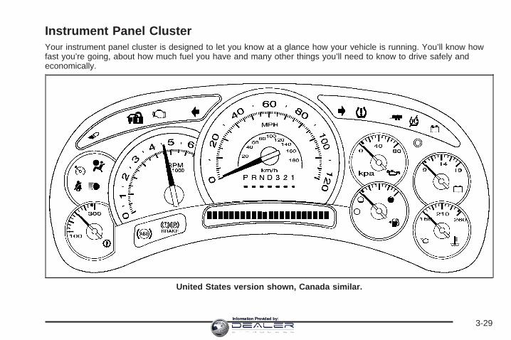
Instrument Panel ClusterYour instrument panel cluster is designed to let you know at a glance how your vehicle is running. You’ll know howfast you’re going, about how much fuel you have and many other things you’ll need to know to drive safely andeconomically.
United States version shown, Canada similar.
3-29Information Provided by:

Speedometer and OdometerYour speedometer lets you see your speed in bothmiles per hour (mph) and kilometers per hour (km/h).
Your vehicle’s odometer works together with thedriver information center. You can set a Trip A andTrip B odometer. See “Trip Information” under DICOperation and Displays on page 3-45.
The odometer mileage can be checked without thevehicle running. Simply press the trip stem on theinstrument panel cluster.
If your vehicle ever needs a new odometer installed, thenew one will be set to the correct mileage total of theold odometer.
Trip OdometerThe trip odometer can tell you how far your vehicle hasbeen driven since you last set the trip odometer to zero.
Press the reset button, located on the instrument panelcluster next to the trip odometer display, to togglebetween the trip odometer and the regular odometer.Holding the reset button for approximately one secondwhile the trip odometer is displayed will reset it.
To display the odometer reading with the ignition off,press the reset button.
TachometerYour tachometer displays the engine speed inrevolutions per minute (rpm).
Safety Belt Reminder LightWhen the key is turned to RUN or START, a chime willbe provided for several seconds to remind people tobuckle their safety belts. The driver safety belt light willalso be provided and stay on for several seconds,then it will flash for several more. You should buckleyour seat belt.
This chime and light will berepeated if the driverremains unbuckled and thevehicle is in motion.
See DIC Warnings and Messages on page 3-48 formore information on driver and passenger safetybelt reminders.
If the driver’s belt is buckled, neither the chime nor thelight will come on.
See Passenger Sensing System on page 1-60 for moreinformation.
3-30Information Provided by:

Airbag Readiness LightThere is an airbag readiness light on the instrumentpanel, which shows the airbag symbol. The systemchecks the airbag’s electrical system for malfunctions.The light tells you if there is an electrical problem.The system check includes the airbag sensors, theairbag modules, the wiring and the crash sensing anddiagnostic module. For more information on theairbag system, see Airbag System on page 1-52.
This light will come onwhen you start yourvehicle, and it will flash fora few seconds. Then thelight should go out. Thismeans the system is ready.
If the airbag readiness light stays on after you start thevehicle or comes on when you are driving, yourairbag system may not work properly. Have your vehicleserviced right away.
{CAUTION:
If the airbag readiness light stays on after youstart your vehicle, it means the airbag systemmay not be working properly. The airbags inyour vehicle may not inflate in a crash, or theycould even inflate without a crash. To help avoidinjury to yourself or others, have your vehicleserviced right away if the airbag readiness lightstays on after you start your vehicle.
The airbag readiness light should flash for a fewseconds when you turn the ignition key to RUN. If thelight doesn’t come on then, have it fixed so it willbe ready to warn you if there is a problem.
3-31Information Provided by:

Passenger Airbag Status IndicatorIf your vehicle has a passenger sensing system, yourrearview mirror will have a passenger airbag statusindicator.
When the ignition key is turned to RUN or START, thepassenger airbag status indicator will light ON andOFF, or the symbol for on and off, for several secondsas a system check. Then, after several more seconds,the status indicator will light either ON or OFF, or eitherthe on or off symbol to let you know the status of theright front passenger’s frontal airbag.
If the word ON or the on symbol is lit on the passengerairbag status indicator, it means that the right frontpassenger’s frontal airbag is enabled (may inflate).
{CAUTION:
If the on indicator comes on when you have arear-facing child restraint installed in the rightfront passenger’s seat, it means that thepassenger sensing system has not turned offthe passenger’s frontal airbag. A child in arear-facing child restraint can be seriouslyinjured or killed if the right front passenger’sairbag inflates. This is because the back of therear-facing child restraint would be very closeto the inflating airbag. Do not use a rear-facingchild restraint in the right front passenger’sseat if the airbag is turned on.
Passenger Airbag Status Indicator – United States
Passenger Airbag Status Indicator – Canada
3-32Information Provided by:

Your vehicle has a rear seat that will accommodate arear-facing child restraint. A label on your sun visor says,“Never put a rear-facing child seat in the front.” This isbecause the risk to the rear-facing child is so great,if the airbag deploys.
{CAUTION:
Even though the passenger sensing system isdesigned to turn off the passenger’s frontalairbag if the system detects a rear-facing childrestraint, no system is failsafe, and no one canguarantee that an airbag will not deploy undersome unusual circumstance, even though it isturned off. We recommend that rear-facingchild restraints be secured in the rear seat,even if the airbag is off.
If the word OFF or the off symbol is lit on the airbagstatus indicator, it means that the passenger sensingsystem has turned off the right front passenger’s frontalairbag. See Passenger Sensing System on page 1-60for more on this, including important safety information.
If, after several seconds, all status indicator lightsremain on, or if there are no lights at all, there may be aproblem with the lights or the passenger sensingsystem. See your dealer for service.
{CAUTION:
If the off indicator and the airbag readinesslight ever come on together, it means thatsomething may be wrong with the airbagsystem. If this ever happens, have the vehicleserviced promptly, because an adult-sizeperson sitting in the right front passenger seatmay not have the protection of the frontalairbag. See Airbag Readiness Light onpage 3-31.
3-33Information Provided by:
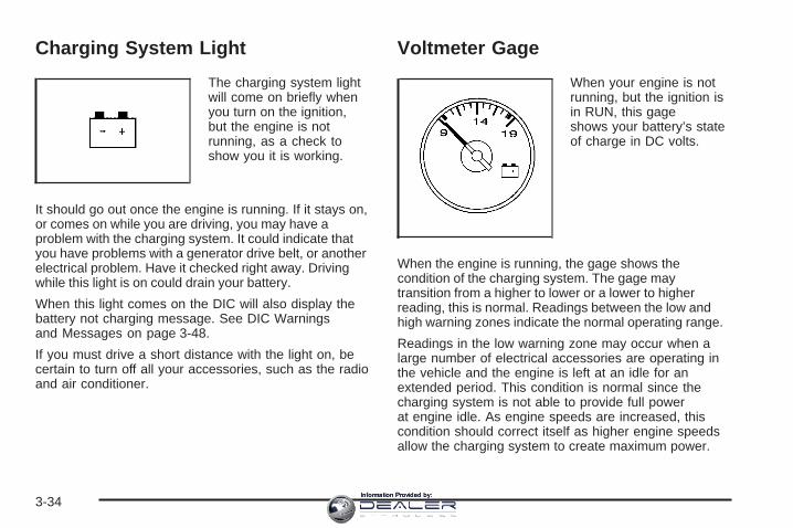
Charging System Light
The charging system lightwill come on briefly whenyou turn on the ignition,but the engine is notrunning, as a check toshow you it is working.
It should go out once the engine is running. If it stays on,or comes on while you are driving, you may have aproblem with the charging system. It could indicate thatyou have problems with a generator drive belt, or anotherelectrical problem. Have it checked right away. Drivingwhile this light is on could drain your battery.
When this light comes on the DIC will also display thebattery not charging message. See DIC Warningsand Messages on page 3-48.
If you must drive a short distance with the light on, becertain to turn off all your accessories, such as the radioand air conditioner.
Voltmeter Gage
When your engine is notrunning, but the ignition isin RUN, this gageshows your battery’s stateof charge in DC volts.
When the engine is running, the gage shows thecondition of the charging system. The gage maytransition from a higher to lower or a lower to higherreading, this is normal. Readings between the low andhigh warning zones indicate the normal operating range.
Readings in the low warning zone may occur when alarge number of electrical accessories are operating inthe vehicle and the engine is left at an idle for anextended period. This condition is normal since thecharging system is not able to provide full powerat engine idle. As engine speeds are increased, thiscondition should correct itself as higher engine speedsallow the charging system to create maximum power.
3-34Information Provided by:
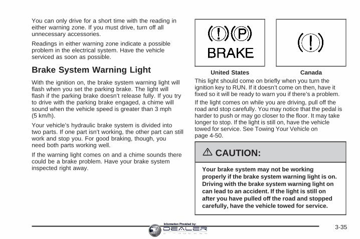
You can only drive for a short time with the reading ineither warning zone. If you must drive, turn off allunnecessary accessories.
Readings in either warning zone indicate a possibleproblem in the electrical system. Have the vehicleserviced as soon as possible.
Brake System Warning LightWith the ignition on, the brake system warning light willflash when you set the parking brake. The light willflash if the parking brake doesn’t release fully. If you tryto drive with the parking brake engaged, a chime willsound when the vehicle speed is greater than 3 mph(5 km/h).
Your vehicle’s hydraulic brake system is divided intotwo parts. If one part isn’t working, the other part can stillwork and stop you. For good braking, though, youneed both parts working well.
If the warning light comes on and a chime sounds therecould be a brake problem. Have your brake systeminspected right away.
This light should come on briefly when you turn theignition key to RUN. If it doesn’t come on then, have itfixed so it will be ready to warn you if there’s a problem.If the light comes on while you are driving, pull off theroad and stop carefully. You may notice that the pedal isharder to push or may go closer to the floor. It may takelonger to stop. If the light is still on, have the vehicletowed for service. See Towing Your Vehicle onpage 4-50.
{CAUTION:
Your brake system may not be workingproperly if the brake system warning light is on.Driving with the brake system warning light oncan lead to an accident. If the light is still onafter you have pulled off the road and stoppedcarefully, have the vehicle towed for service.
United States Canada
3-35Information Provided by:

Anti-Lock Brake SystemWarning Light
With the anti-lock brakesystem, this light will comeon when you start yourengine and may stay on forseveral seconds.
That’s normal. If the light doesn’t come on then, have itfixed so it will be ready to warn you if there is a problem.
If the light stays on, or comes on when you’re driving,your vehicle needs service. You will also hear achime sound when the light is on steady. If the regularbrake system warning light isn’t on, you still havebrakes, but you don’t have anti-lock brakes. If theregular brake system warning light is also on you don’thave anti-lock brakes and there’s a problem withyour regular brakes. In addition to both lights, you willalso hear a chime sound on the first occurrence ofa problem and each time the vehicle is shut off and thenrestarted. See Brake System Warning Light onpage 3-35.
Low Tire Pressure Warning Light
This light and a chime willcome on along with theCHECK TIRE PRESSUREmessage in the DICwhen one or more of yourtires is significantlyunder-inflated.
This light will also come on briefly when you startthe engine.
See “CHECK TIRE PRESSURE” under DIC Warningsand Messages on page 3-48 for more information.
Stop and check your tires as soon as possible,and inflate them to the proper pressure as indicated onthe vehicle’s certification/tire label. See Tires onpage 5-60 for more information on your vehicle’s tires.
3-36Information Provided by:

Traction Off Light
If you have theStabiliTrak® system, thislight should come on brieflywhen you turn theignition to RUN.
If the light doesn’t come on then, the system mayrequire service; have it fixed so it will be there to warnyou if the system is turned off.
For more information on the traction off light, seeStabiliTrak® System on page 4-9.
Engine Coolant Temperature Gage
This gage shows the engine coolant temperature.
It also provides an indicator of how hard your vehicle isworking. During a majority of the operation, the gagewill read 210°F (100°C) or less. If you are pulling a loador going up hills, it is normal for the temperature tofluctuate and approach the 250°F (122°C) mark. If thegage reaches the 260°F (125°C) mark, it indicatesthat the cooling system is working beyond its capacity.
See Engine Overheating on page 5-26.
United States Canada
3-37Information Provided by:

Transmission Temperature Gage
Your vehicle is equipped with a transmissiontemperature gage.
When your ignition is on, the gage shows thetemperature of the transmission fluid. The normaloperating range is from 180°F (82°C) to about200°F (93°C).
At approximately 265°F (130°C), the DIC will display aTRANSMISSION HOT message and the transmissionwill enter a transmission protection mode. Whenthe transmission enters the protection mode, you maynotice a change in the transmission shifting patterns.The transmission will return to normal shifting patternswhen the transmission fluid temperature falls below260°F (127°C).
See Driver Information Center (DIC) on page 3-45 forfurther information.If the transmission fluid reaches temperatures ofapproximately 275°F (135°C) or greater, the DIC willdisplay a TRANS HOT IDLE ENGINE warning messageand a chime will sound. Pull the vehicle off theroadway when it is safe to do so. Set the parking brake,place the transmission in PARK (P) and allow theengine to idle until the transmission temperature fallsbelow 260°F (127°C). If the transmission continuesto operate above 265°F (130°C), please contact yournearest dealer or the Roadside Assistance Center. SeeRoadside Service on page 7-6 for more information.
Notice: If you drive your vehicle with thetransmission temperature gage above normaloperating range, you can damage the transmission.This could lead to costly repairs that would notbe covered by your warranty. Do not drive yourvehicle while the transmission temperature gagereading is above normal. See your dealer for service.The following situations can cause the transmission tooperate at higher temperatures:• Towing a trailer,• hot outside air temperatures,• hauling a large or heavy load,• low transmission fluid level,• high transmission fluid level,• restricted air flow to the radiator.
United States Canada
3-38Information Provided by:

Malfunction Indicator Lamp
Check Engine LightYour vehicle is equippedwith a computer whichmonitors operation of thefuel, ignition, and emissioncontrol systems.
This system is called OBD II (On-BoardDiagnostics-Second Generation) and is intended toassure that emissions are at acceptable levels for thelife of the vehicle, helping to produce a cleanerenvironment. The check engine light comes on toindicate that there is a problem and service is required.Malfunctions often will be indicated by the systembefore any problem is apparent. This may prevent moreserious damage to your vehicle. This system is alsodesigned to assist your service technician in correctlydiagnosing any malfunction.
Notice: If you keep driving your vehicle with thislight on, after awhile, your emission controlsmay not work as well, your fuel economy may notbe as good, and your engine may not run assmoothly. This could lead to costly repairs thatmay not be covered by your warranty.
Notice: Modifications made to the engine,transmission, exhaust, intake, or fuel system ofyour vehicle or the replacement of the original tireswith other than those of the same Tire PerformanceCriteria (TPC) can affect your vehicle’s emissioncontrols and may cause this light to come on.Modifications to these systems could lead to costlyrepairs not covered by your warranty. This mayalso result in a failure to pass a required EmissionInspection/Maintenance test. See Accessoriesand Modifications on page 5-3.
This light should come on, as a check to show you it isworking, when the ignition is on and the engine isnot running. If the light does not come on, have itrepaired. This light will also come on during amalfunction in one of two ways:
• Light Flashing — A misfire condition has beendetected. A misfire increases vehicle emissionsand may damage the emission control system onyour vehicle. Diagnosis and service may berequired.
• Light On Steady — An emission control systemmalfunction has been detected on your vehicle.Diagnosis and service may be required.
3-39Information Provided by:

If the Light is FlashingThe following may prevent more serious damage toyour vehicle:
• Reducing vehicle speed
• Avoiding hard accelerations
• Avoiding steep uphill grades
• If you are towing a trailer, reduce the amount ofcargo being hauled as soon as it is possible
If the light stops flashing and remains on steady,see “If the Light Is On Steady” following.
If the light continues to flash, when it is safe to do so,stop the vehicle. Find a safe place to park your vehicle.Turn the key off, wait at least 10 seconds and restartthe engine. If the light remains on steady, see “If theLight Is On Steady” following. If the light is still flashing,follow the previous steps, and see your dealer forservice as soon as possible.
If the Light Is On SteadyYou may be able to correct the emission systemmalfunction by considering the following:
Did you recently put fuel into your vehicle?
If so, reinstall the fuel cap, making sure to fully installthe cap. See Filling the Tank on page 5-8. Thediagnostic system can determine if the fuel cap has
been left off or improperly installed. A loose or missingfuel cap will allow fuel to evaporate into the atmosphere.A few driving trips with the cap properly installedshould turn the light off.
Did you just drive through a deep puddle of water?
If so, your electrical system may be wet. The conditionwill usually be corrected when the electrical systemdries out. A few driving trips should turn the light off.
Have you recently changed brands of fuel?
If so, be sure to fuel your vehicle with quality fuel. SeeGasoline Octane on page 5-5. Poor fuel quality willcause your engine not to run as efficiently as designed.You may notice this as stalling after start-up, stallingwhen you put the vehicle into gear, misfiring, hesitationon acceleration, or stumbling on acceleration. (Theseconditions may go away once the engine is warmed up.)This will be detected by the system and cause thelight to turn on.
If you experience one or more of these conditions,change the fuel brand you use. It will require at leastone full tank of the proper fuel to turn the light off.
If none of the above steps have made the light turn off,your dealer can check the vehicle. Your dealer has theproper test equipment and diagnostic tools to fix anymechanical or electrical problems that may havedeveloped.
3-40Information Provided by:

Emissions Inspection andMaintenance ProgramsSome state/provincial and local governments have ormay begin programs to inspect the emission controlequipment on your vehicle. Failure to pass thisinspection could prevent you from getting a vehicleregistration.
Here are some things you need to know to help yourvehicle pass an inspection:
Your vehicle will not pass this inspection if the checkengine light is on or not working properly.
Your vehicle will not pass this inspection if the OBD(on-board diagnostic) system determines that criticalemission control systems have not been completelydiagnosed by the system. The vehicle would beconsidered not ready for inspection. This can happen ifyou have recently replaced your battery or if yourbattery has run down. The diagnostic system isdesigned to evaluate critical emission control systemsduring normal driving. This may take several daysof routine driving. If you have done this and your vehiclestill does not pass the inspection for lack of OBDsystem readiness, your GM dealer can prepare thevehicle for inspection.
Oil Pressure Gage
The oil pressure gage shows the engine oil pressurein psi (pounds per square inch) when the engineis running. Canadian vehicles indicate pressure inkPa (kilopascals).
Oil pressure may vary with engine speed, outsidetemperature and oil viscosity, but readings above thelow pressure zone indicate the normal operating range.
United States Canada
3-41Information Provided by:

A reading in the low pressure zone may be caused by adangerously low oil level or some other problemcausing low oil pressure. Check your oil as soon aspossible. See DIC Warnings and Messages onpage 3-48.
{CAUTION:
Do not keep driving if the oil pressure is low.If you do, your engine can become so hot thatit catches fire. You or others could be burned.Check your oil as soon as possible and haveyour vehicle serviced.
Notice: Lack of proper engine oil maintenance maydamage the engine. The repairs would not be coveredby your warranty. Always follow the maintenanceschedule in this manual for changing engine oil.
Security Light
This light will come onbriefly when you turnthe key toward START.The light will stay onuntil the engine starts.
If the light flashes, the Passlock® system has entered atamper mode. If the vehicle fails to start, see Passlock®
on page 2-25.
If the light comes on continuously while driving andstays on, there may be a problem with the Passlock®
system. Your vehicle will not be protected by Passlock®,and you should see your dealer.
Also, see Content Theft-Deterrent on page 2-23 foradditional information regarding the security light.
3-42Information Provided by:

Cruise Control Light
This light comes onwhenever you set yourcruise control.
The light will go out when the cruise control isturned off. See Cruise Control on page 3-10 formore information.
Highbeam On Light
This light will come onwhen the high-beamheadlamps are in use.
See Headlamp High/Low-Beam Changer on page 3-8.
Tow/Haul Mode Light
This light is displayedwhen the tow/haul modehas been activated.
For more information, see “Tow/Haul Mode” underTowing a Trailer on page 4-50.
Cargo Lamp Light
This light will come onwhen the cargo lamp is inuse. For more informationsee Exterior CargoLamps on page 3-17.
3-43Information Provided by:

Fuel Gage
When the ignition is on,the fuel gage tells youabout how much fuel youhave left in your tank.
The gage will first indicate empty before you areout of fuel, and you should get more fuel as soonas possible.
Here are some situations you may experience with yourfuel gage. None of these indicate a problem with thefuel gage.
• At the gas station, the fuel pump shuts off beforethe gage reads full.
• It takes a little more or less fuel to fill up than thefuel gage indicated. For example, the gage mayhave indicated the tank was half full, but it actuallytook a little more or less than half the tank’scapacity to fill the tank.
• The gage goes back to empty when you turn off theignition.
Low Fuel Warning LightThe light next to the fuel gage will come on briefly whenyou are starting the engine.
This light comes on when the fuel tank is low on fuel.To turn it off, add fuel to the fuel tank. See Fuel onpage 5-5.
3-44Information Provided by:

Driver Information Center (DIC)The Driver Information Center (DIC) display is locatedon the instrument panel cluster, below the speedometer.The DIC buttons are located on the steering wheel.The DIC can display information such as the tripodometer, fuel economy, customization features, andwarning/status messages.
3 (Trip Information): Press this button to displaythe odometer, trip odometers, tire pressure for vehicleswith a tire pressure monitor, timer, and engine hours.
t (Fuel Information): Press this button to display thecurrent range, fuel used, average fuel economy, andengine oil life.
4 (Customization): Press this button to access thevehicle settings menu and customize the personalsettings on your vehicle.
r (Select): Press this button to reset certain DICfunctions and set your customization settings.
Pressing any of the four DIC buttons or the trip odometerreset stem will acknowledge DIC messages and clearthem from the DIC display.
DIC Operation and DisplaysThe Driver Information Center (DIC) comes on when theignition is on. After a short delay, the DIC will displaythe information that was last displayed before the enginewas turned off.
The DIC has different modes which can be accessed bypressing the four DIC buttons located on the steeringwheel. These buttons are trip information, fuelinformation, customization, and select. The buttonfunctions are detailed in the following pages.
3-45Information Provided by:

Trip Information Button
3 (Trip Information): Press the trip informationbutton to scroll through the ODOMETER, TRIP A,TRIP B, TIRE PRESSURES, TIMER, andENGINE HOURS.
Odometer: Press the trip information button untilODOMETER appears on the display. This mode showsthe total distance the vehicle has been driven ineither miles or kilometers. Pressing the reset stemlocated on the instrument cluster with the vehicle off willalso display the odometer.
Trip A: Press the trip information button until TRIP Aappears on the display. This mode shows the currentdistance traveled since the last reset for TRIP A in eithermiles or kilometers.
Trip B: Press the trip information button until TRIP Bappears on the display. This mode shows the currentdistance traveled since the last reset for TRIP B in eithermiles or kilometers.
To reset TRIP A or TRIP B information, press and holdthe select button for one second while in one of thetrip modes. This will reset the information for TRIP Aor TRIP B.
You can also reset TRIP A or TRIP B while they aredisplayed by pressing the reset stem on the cluster.If you press and hold the reset stem or the select buttonfor four seconds, the display will show the distancetraveled since the last ignition cycle for TRIP A orTRIP B.
See Trip Odometer on page 3-30 for more information.
Tire Pressures: The tire pressure mode is availableonly on vehicles equipped with a tire pressure monitor.Press the trip information button until TIRE PRESSURESappears on the display. This mode shows the tirepressure in pounds per square inch (psi) or kilopascals(kPa). Press the select button to scroll through thefollowing information:
• LF TIRE shows the tire pressure for the front driver’sside tire.
• RF TIRE shows the tire pressure for the frontpassenger’s side tire.
• LR TIRE shows the tire pressure for the rear driver’sside tire.
• RR TIRE shows the tire pressure for the rearpassenger’s side tire.
3-46Information Provided by:

Timer: The DIC can be used as a timer. Press theselect button while TIMER is displayed to start the timer.The display will show the amount of time that haspassed since the timer was last reset, not including timethe ignition is off. Time will continue to be counted aslong as the ignition is on, even if another display is beingshown on the DIC. The timer will record up to 99 hours,59 minutes and 59 seconds (99:59:59) after whichthe display will roll back to zero.
To stop the counting of time, press the select buttonbriefly while TIMER is displayed.
To reset the timer to zero, press and hold the selectbutton while TIMER is displayed.
Engine Hours: Press the trip information button untilENGINE HOURS appears on the display. Thismode shows the total number of hours the engine hasrun. Pressing and holding the reset stem located onthe instrument cluster for about four seconds will alsodisplay the engine hour information after the odometer isdisplayed when the vehicle is off.
Fuel Information Buttont (Fuel Information): Press the fuel informationbutton to scroll through the range, fuel used, averagefuel economy, and the engine oil life system.
Fuel Range: Press the fuel information button untilRANGE appears on the display. This mode shows theremaining distance you can drive without refueling. It isbased on fuel economy and the fuel remaining in the fueltank. The display will show LOW if the fuel level is low.
The fuel economy data used to determine fuel range is anaverage of recent driving conditions. As your drivingconditions change, this data is gradually updated.Fuel range cannot be reset.
Fuel Used: Press the fuel information button untilFUEL USED appears on the display. This mode showsthe number of gallons or liters of fuel used since thelast reset of this menu item. To reset the fuel usedinformation, press and hold the select button forone second while FUEL USED is displayed.
Average Fuel Economy: Press the fuel informationbutton until AVG ECON appears on the display.This mode shows how many miles per gallon (MPG) orliters per 100 kilometers (L/100 km) your vehicle isgetting based on current and past driving conditions.
Press and hold the select button for one second whileAVG ECON is displayed to reset the average fueleconomy. Average fuel economy will then be calculatedstarting from that point. If the average fuel economy is notreset, it will be continually updated each time you drive.
3-47Information Provided by:

Engine Oil Life System: Press the fuel informationbutton until ENGINE OIL LIFE appears on the display.The engine oil life system shows an estimate of theoil’s remaining useful life. It will show 100% when thesystem is reset after an oil change. It will alert youto change your oil on a schedule consistent with yourdriving conditions.Always reset the engine oil life system after an oilchange. To reset the engine oil life system, see EngineOil Life System on page 5-17.
In addition to the engine oil life system monitoring theoil life, additional maintenance is recommended in theMaintenance Schedule in this manual. See Engine Oil onpage 5-14 and Scheduled Maintenance on page 6-4.
Customization Button4 (Customization): Press the customization button toaccess the VEHICLE SETTINGS menu and customizethe settings to your vehicle. See DIC VehicleCustomization on page 3-57 for more information.
Select Buttonr (Select): Press the select button to reset certainDIC functions and set your customization settings.For example, this button will reset the trip odometersand enables you to scroll through and select thelanguage in which the DIC information will appear.
DIC Warnings and MessagesWarning messages are displayed on the DriverInformation Center (DIC) to notify the driver that thestatus of the vehicle has changed and that some actionmay be needed by the driver to correct the condition.If there is more than one message that needs to bedisplayed they will appear one after another. Somemessages may not require immediate action, but youshould press any of the four DIC buttons on the steeringwheel or the trip odometer reset stem on the instrumentpanel cluster to acknowledge that you received themessages and to clear them from the display. Somemessages cannot be cleared from the display becausethey are more urgent. These messages require actionbefore they can be removed from the DIC display. Youshould take any messages that appear on the displayseriously and remember that clearing the messages willonly make the messages disappear, not correct theproblem. The following are the possible messages thatcan be displayed and some information about them.
3-48Information Provided by:

BATTERY NOT CHARGINGOn some vehicles, if the battery is not charging duringoperation, this message will appear on the DIC.Driving with this problem could drain your battery. Havethe electrical system checked by your GM dealer assoon as possible. Pressing any of the four DIC buttonsor the trip odometer reset stem will clear the messagefrom the DIC display. See Charging System Lighton page 3-34 and Voltmeter Gage on page 3-34.
BUCKLE PASSENGERIf your vehicle has the passenger sensing system, thismessage reminds you to buckle the passenger’sseat belt. See Passenger Sensing System on page 1-60.
This message will display and a chime will sound whenthe ignition is on, the driver’s seat belt is buckled, thepassenger’s seat belt is unbuckled with the passengerairbag enabled, and the vehicle is in motion. You shouldhave the passenger buckle their seat belt.
This reminder will be repeated if the ignition is on, thevehicle is in motion, the driver is buckled and thepassenger is still unbuckled, and the passenger airbagis enabled. If the passenger’s seat belt is alreadybuckled, this message and chime will not come on.
Pressing any of the four DIC buttons or the trip odometerreset stem will acknowledge the message and clear itfrom the DIC display.
BUCKLE SEATBELTIf your vehicle has the passenger sensing system, thismessage reminds you to buckle the driver’s seatbelt. See Passenger Sensing System on page 1-60.
This message will display and a chime will sound whenthe ignition is on, the driver’s seat belt is unbuckled,and the vehicle is in motion. You should buckleyour seat belt.
If the driver remains unbuckled when the ignition is onand the vehicle is in motion, the reminder will berepeated. If the driver’s seat belt is already buckled, thismessage and chime will not come on.
This message is an additional reminder to the SafetyBelt Reminder Light in the instrument panel cluster. SeeSafety Belt Reminder Light on page 3-30.
Pressing any of the four DIC buttons or the trip odometerreset stem will acknowledge the message and clear itfrom the DIC display.
3-49Information Provided by:

CHANGE ENGINE OILThis message is displayed when the engine oil needs tobe changed and service is required for your vehicle.See your GM dealer. See Scheduled Maintenanceon page 6-4 and Engine Oil on page 5-14 for moreinformation. Also see Engine Oil Life System onpage 5-17 for information on how to reset the message.This message will clear itself after 10 seconds untilthe next ignition cycle.
CHARGING SYSTEM FAILUREOn some vehicles, if there is a problem with thegenerator and battery charging system, this message willappear on the DIC, a chime will sound and the chargingsystem light on the instrument panel cluster will come on.See Charging System Light on page 3-34 and VoltmeterGage on page 3-34 for more information. Driving with thisproblem could drain your battery. Turn off all unnecessaryaccessories. Stop and turn off the vehicle as soon as it issafe to do so. Have the electrical system checked by yourGM dealer immediately.
CHECK OIL LEVELIf the oil level in the vehicle is low, this message willappear on the DIC. Check the oil level and correct it asnecessary. You may need to let the vehicle cool orwarm up and cycle the ignition to be sure this message
will clear. Once the problem is corrected, pressing anyof the four DIC buttons or the trip odometer resetstem will clear the message from the DIC display.This message will clear itself after 10 seconds until thenext ignition cycle.
CHECK TIRE PRESSUREIf low tire pressure is detected in any of the vehicle’stires, this message will appear on the DIC, along with achime and a low tire pressure warning light. See LowTire Pressure Warning Light on page 3-36. Pressing anyof the four DIC buttons or the trip odometer resetstem will clear the message from the DIC display. It willappear at each ignition cycle until the tires are inflatedto the correct inflation pressure.
See Tire Pressure Monitor System on page 5-69 formore information on tires and the correct inflationpressures.
CHECK WASHER FLUIDIf the washer fluid level is low, this message will appearon the DIC. Adding washer fluid to the windshieldwasher reservoir will clear the message. See WindshieldWasher Fluid on page 5-35. Pressing any of thefour DIC buttons or the trip odometer reset stemwill clear the message from the DIC display. Thismessage will clear itself after 10 seconds until the nextignition cycle.
3-50Information Provided by:

DRIVER DOOR AJARIf the driver’s door is not fully closed and the vehicle isin a drive gear, this message will appear on thedisplay and you will hear a chime. Stop and turn off thevehicle, check the door for obstacles, and close thedoor again. Check to see if the message still appears onthe DIC. Pressing any of the four DIC buttons or thetrip odometer reset stem will clear the message from theDIC display.
ENGINE COOLANT HOTIf the cooling system temperature gets hot, this messagewill appear in the DIC. Turn off the air conditioning.If the message is still on, or if the engine coolanttemperature gage continues to rise, pull the vehicleover when it is safe to do so. See Engine CoolantTemperature Gage on page 3-37 for more information.Stop the vehicle and let the engine idle in PARK (P)for a few minutes to allow the coolant to reach asafe temperature. This message will clear when thecoolant temperature drops to a safe operatingtemperature. Pressing any of the four DIC buttons orthe trip odometer reset stem will clear the message fromthe DIC display.
ENGINE OVERHEATED
Notice: If you drive your vehicle while the engine isoverheating, severe engine damage may occur.If an overheat warning appears on the instrumentpanel cluster and/or DIC, stop the vehicle as soon aspossible. Do not increase the engine speed abovenormal idling speed. See Engine Overheatingon page 5-26 for more information.
If the engine cooling system reaches unsafetemperatures for operation, this message will appear inthe DIC and you will hear a chime. Stop and turn offthe vehicle as soon as it is safe to do so to avoid severedamage. This message will clear when the enginehas cooled to a safe operating temperature.
FUEL LEVEL LOWIf the fuel level is low, this message will appear on theDIC and you will hear a chime. Refuel as soon aspossible. Pressing any of the four DIC buttons or thetrip odometer reset stem will clear the message from theDIC display. It will also clear itself after 10 secondsuntil the next ignition cycle. The low fuel light near thefuel gage will still remain on in either case. See LowFuel Warning Light on page 3-44, Fuel Gage onpage 3-44, and Fuel on page 5-5.
3-51Information Provided by:

KEYFOB X BATTERY LOWIf a remote keyless entry transmitter battery is low,this message will appear on the DIC. The batteryneeds to be replaced in the transmitter. See “BatteryReplacement” under Remote Keyless Entry SystemOperation on page 2-5. Pressing any of the four DICbuttons or the trip odometer reset stem will clear themessage from the DIC display.
LEFT REAR DOOR AJARIf the driver’s side rear door is not fully closed and thevehicle is in a drive gear, this message will appearon the display and you will hear a chime. Stop and turnoff the vehicle, check the door for obstacles, andclose the door again. Check to see if the message stillappears on the DIC. Pressing any of the four DICbuttons or the trip odometer reset stem will clear themessage from the DIC display.
OIL LIFE RESETThis message will appear on the display for about10 seconds after resetting the change engine oilmessage. See “Engine Oil Life System” under DICOperation and Displays on page 3-45 and Engine Oilon page 5-14.
OIL PRESSURE LOW
Notice: If you drive your vehicle while the engineoil pressure is low, severe engine damage mayoccur. If a low oil pressure warning appears on theDriver Information Center (DIC), stop the vehicleas soon as possible. Do not drive the vehicle untilthe cause of the low oil pressure is corrected.See Engine Oil on page 5-14 for more information.
If low oil pressure levels occur, this message willbe displayed on the DIC and a chime will sound.Stop the vehicle as soon as safely possible and do notoperate it until the cause of the low oil pressure hasbeen corrected. Check your oil as soon as possible andhave your vehicle serviced by your GM dealer.
PASSENGER DOOR AJARIf the passenger’s door is not fully closed and thevehicle is in a drive gear, this message will appear onthe display and you will hear a chime. Stop and turn offthe vehicle, check the door for obstacles, and closethe door again. Check to see if the message stillappears on the DIC. Pressing any of the four DICbuttons or the trip odometer reset stem will clear themessage from the DIC display.
3-52Information Provided by:

REDUCED ENGINE POWERThis message is displayed and a chime will sound whenthe cooling system temperature gets too hot and theengine further enters the engine coolant protectionmode. See Engine Overheating on page 5-26 forfurther information.
You may also see this message when the vehicledetermines a problem with the electronic throttle control.See your GM dealer for service.
RIGHT REAR DOOR AJARIf the passenger’s side rear door is not fully closed andthe vehicle is in a drive gear, this message willappear on the display and you will hear a chime.Stop and turn off the vehicle, check the door forobstacles, and close the door again. Check to see if themessage still appears on the DIC. Pressing any ofthe four DIC buttons or the trip odometer reset stem willclear the message from the DIC display.
SERVICE 4WD (Four-Wheel-Drive)If a problem occurs with the all-wheel-drive system,this message will appear on the DIC. If this messageappears, stop as soon as possible and turn off thevehicle. Restart the vehicle and check for the message
on the DIC display. If the message is still displayedor appears again when you begin driving, theall-wheel-drive system needs service. See yourGM dealer. Pressing any of the four DIC buttons or thetrip odometer reset stem will clear the message fromthe DIC display.
SERVICE AIR BAGIf there is a problem with the airbag system, thismessage will be displayed on the DIC. Have yourGM dealer inspect the system for problems. See AirbagReadiness Light on page 3-31 and Airbag System onpage 1-52 for more information. Pressing any of thefour DIC buttons or the trip odometer reset stemwill clear the message from the DIC display.
SERVICE BRAKE SYSTEMIf a problem occurs with the brake system, this messagewill appear on the DIC. If this message appears, stopas soon as possible and turn off the vehicle. Restart thevehicle and check for the message on the DIC display.If the message is still displayed or appears againwhen you begin driving, the brake system needs service.See your GM dealer. Pressing any of the four DICbuttons or the trip odometer reset stem will clear themessage from the DIC display.
3-53Information Provided by:
SERVICE CHARGING SYSTEMOn some vehicles, if there is a problem with the batterycharging system, this message will appear on the DIC.Under certain conditions, the charging system light mayalso turn on in the instrument panel cluster. See ChargingSystem Light on page 3-34. The battery will not becharging at an optimal rate and the vehicle will lose theability to enter the fuel economy mode. The vehicle issafe to drive, however you should have the electricalsystem checked by your GM dealer. Pressing any of thefour DIC buttons or the trip odometer reset stem will clearthe message from the DIC display.
SERVICE RIDE CONTROLIf a problem occurs with the suspension system, thismessage will appear on the DIC. See your GM dealer.Pressing any of the four DIC buttons or the tripodometer reset stem will clear the message from theDIC display.
SERVICE STABILITYIf you ever see the SERVICE STABILITY message, itmeans there may be a problem with your StabiliTrak®
system. If you see this message, try to reset the system.Stop; turn off the engine; then start the engine again.
If the SERVICE STABILITY message still comes on,it means there is a problem. You should see yourGM dealer for service. The vehicle is safe to drive,however, you do not have the benefit of StabiliTrak®,so reduce your speed and drive accordingly.
For more information on the StabiliTrak® system,see StabiliTrak® System on page 4-9.
SERVICE TIRE MONITORThis message will be displayed if any of the tire monitorsensors have malfunctioned, if the tire monitor sensorshave not been programmed or if the recommendedtire pressures are not programmed. See your GM dealer.Pressing any of the four DIC buttons or the tripodometer reset stem will clear the message from theDIC display.
STABILITY SYS (System) ACTIVEYou may see the STABILITY SYS ACTIVE message onthe DIC. It means that an advanced computer-controlledsystem has come on to help your vehicle continue togo in the direction in which you are steering.
For more information on the StabiliTrak® system,see StabiliTrak® System on page 4-9.
3-54Information Provided by:

STABILITY SYS (System) DISABLEDThe STABILITY SYS DISABLED message will turn onwhen you press the StabiliTrak® button or when thestability control has been automatically disabled.There are four conditions that can cause this messageto appear.
• One condition is overheating, which could occur ifStabiliTrak® activates continuously for an extendedperiod of time.
• The message will also be displayed if the brakesystem warning light is on. See Brake SystemWarning Light on page 3-35.
• The message could be displayed if the stabilitysystem takes longer than usual to complete itsdiagnostic checks due to driving conditions.
• Also, if an engine or vehicle related problem hasbeen detected, and the vehicle needs service, themessage will appear.
The message will turn off as soon as the conditionsthat caused the message to be displayed are nolonger present.
For more information on the StabiliTrak® system, seeStabiliTrak® System on page 4-9.
TIGHTEN FUEL CAPIf the vehicle’s fuel cap is not tightened properly thismessage may appear along with the check engine lighton the instrument panel. See Malfunction IndicatorLamp on page 3-39. Reinstall the fuel cap, making sureto fully install the cap. See Filling the Tank onpage 5-8. The diagnostic system can determine if thefuel cap has been left off or improperly installed. A looseor missing fuel cap will allow fuel to evaporate intothe atmosphere. A few driving trips with the cap properlyinstalled should turn the light and message off.
TRACTION ACTIVEWhen the traction control system has detected that anyof the vehicle’s wheels are slipping, the tractioncontrol system will activate and this message will appearon the DIC. See StabiliTrak® System on page 4-9 formore information.
TRACTION SYS (System) LIMITEDIf the brake traction control system activates constantlyor if the brakes have heated up due to high-speedbraking, brake traction control will be disabled and theTRACTION SYS LIMITED message will be displayed.The system will return to normal operation after thebrakes have cooled. See StabiliTrak® System onpage 4-9 for more information.
3-55Information Provided by:

TRANS (Transmission) HOT IDLEENGINE
Notice: If you drive your vehicle while thetransmission fluid is overheating and thetransmission temperature warning is displayed onthe instrument panel cluster and/or DIC, youcan damage the transmission. This could lead tocostly repairs that would not be covered byyour warranty. Do not drive your vehicle withoverheated transmission fluid or while thetransmission temperature warning is displayed.
If the transmission fluid in the vehicle gets hot,this message will appear on the DIC along with acontinuous chime. Driving with the transmission fluidtemperature high can cause damage to the vehicle.Stop the vehicle and let it idle to allow the transmissionto cool. This message will clear and the chime willstop when the fluid temperature reaches a safe level.See Transmission Temperature Gage on page 3-38.
TRANSMISSION HOT
Notice: If you drive your vehicle while thetransmission fluid is overheating and thetransmission temperature warning is displayed onthe instrument panel cluster and/or DIC, youcan damage the transmission. This could lead tocostly repairs that would not be covered byyour warranty. Do not drive your vehicle withoverheated transmission fluid or while thetransmission temperature warning is displayed.
If the transmission fluid temperature becomes high,this message will appear on the DIC display.
When the transmission enters the protection mode,you may notice a change in the transmission shiftingpatterns. When the transmission fluid temperaturereturns to normal, the display will turn off and thetransmission shifting patterns will return to normal.
3-56Information Provided by:
If the vehicle has the Tow/Haul mode, use this feature ifthe transmission is operating at higher temperaturesand/or the following situations exist, which can cause thetransmission to operate at higher temperatures:
• Towing a trailer
• Hot outside air temperatures
• Hauling a large or heavy load
• Over-loading
• Low transmission fluid level
• High transmission fluid level
• Restricted air flow to the radiator
A temporary solution to hotter transmission operatingtemperatures may be to let the transmission cool down.If the transmission is operated at higher temperatureson a frequent basis, see Scheduled Maintenanceon page 6-4 for the transmission your vehicle isequipped with for the proper transmission maintenanceintervals. Also see Transmission Temperature Gageon page 3-38 for more information.
TURN SIGNAL ONIf a turn signal is left on for 3/4 of a mile (1.2 km), thismessage will appear on the display and you will hear achime. Move the turn signal/multifunction lever to theoff position. Pressing any of the four DIC buttons or thetrip odometer reset stem will clear the message fromthe DIC display.
DIC Vehicle CustomizationYour vehicle may have customization capabilities thatallow you to program some features to one settingbased on your preference. All of the customizableoptions listed may not be available on your vehicle.Only the options available will be displayed onyour Driver Information Center (DIC).
The default settings for the customization features wereset when your vehicle left the factory, but may havebeen changed from their default state since then.
To change feature preferences, make sure the ignitionis on and the vehicle is in PARK (P). Press thecustomization button to scroll through the availablecustomizable options.
After pressing the customization button, VEHICLESETTINGS will momentarily display before going to acustomization option.
3-57Information Provided by:
Lock DoorsPress the customization button until LOCK DOORSappears in the display. To select your preferencefor automatic locking, press the select button whileLOCK DOORS is displayed on the DIC. Pressing theselect button will scroll through the following choices:
LOCK DOORS: IN GEAR (default): The doors will lockwhen the vehicle is shifted out of PARK (P).
LOCK DOORS: WITH SPEED: The doors will lockwhen the vehicle speed is above 8 mph (13 km/h) forthree seconds.
Choose one of the available options and press thecustomization button while it is displayed on the DIC toselect it and move on to the next feature.
Unlock DoorsPress the customization button until UNLOCK DOORSappears in the display. To select your preference forautomatic unlocking, press the select button whileUNLOCK DOORS is displayed on the DIC. Pressing theselect button will scroll through the following choices:
UNLOCK DOORS: IN PARK (default): All of the doorswill unlock when the vehicle is shifted into PARK (P).
UNLOCK DRIVER: IN PARK: The driver’s door will beunlocked when the vehicle is shifted into PARK (P).
UNLOCK DOORS: KEY OUT: All of the doors willunlock when the key is taken out of the ignition.
UNLOCK DOORS: MANUALLY: The doors will not beunlocked automatically.
Choose one of the available options and press thecustomization button while it is displayed on the DIC toselect it and move on to the next feature.
Door Lock DelayIf your DIC does not have this feature, you can stillprogram the delayed locking feature. See DelayedLocking on page 2-9 for more information.
When locking the doors with the power lock switch orthe remote keyless entry transmitter and a door orthe tailgate is open, the delayed locking featurewill delay locking the doors and tailgate untilfive seconds after the last door is closed.
Press the customization button until DOOR LOCKDELAY appears in the display. To select yourpreference for delayed locking, press the select buttonwhile DOOR LOCK DELAY is displayed on the DIC.Pressing the select button will scroll through thefollowing choices:
DOOR LOCK DELAY: OFF (default): The doors willlock immediately when pressing the power lock switch orthe lock button on the remote keyless entry transmitter.
3-58Information Provided by:

DOOR LOCK DELAY: ON: The doors will not lock untilfive seconds after the last door or the tailgate isclosed. You will hear three chimes to signal that thedelayed locking feature is in use. You can temporarilyoverride delayed locking by pressing the lock buttonon the door or the remote keyless entry transmitter asecond time.Choose one of the available options and press thecustomization button while it is displayed on the DIC toselect it and move on to the next feature.This feature will not operate if the key is in the ignition.
Lock FeedbackPress the customization button until LOCK FEEDBACKappears in the display. To select your preference forthe feedback you receive when locking the vehicle withthe remote keyless entry transmitter, press the selectbutton while LOCK FEEDBACK is displayed on the DIC.Pressing the select button will scroll through thefollowing choices:
LOCK FEEDBACK: BOTH (default): The parkinglamps will flash each time you press the button with thelock symbol on the remote keyless entry transmitterand the horn will chirp the second time you press thelock button.
LOCK FEEDBACK: LAMPS: The parking lamps willflash each time you press the button with the locksymbol on the remote keyless entry transmitter.
LOCK FEEDBACK: HORN: The horn will chirp thesecond time you press the button with the lock symbolon the remote keyless entry transmitter.
LOCK FEEDBACK: OFF: There will be no feedbackwhen locking the vehicle.
Choose one of the available options and press thecustomization button while it is displayed on the DIC toselect it and move on to the next feature.
Unlock FeedbackPress the customization button until UNLOCKFEEDBACK appears in the display. To select yourpreference for the feedback you will receive whenunlocking the vehicle with the remote keyless entrytransmitter, press the select button while UNLOCKFEEDBACK is displayed on the DIC. Pressing the selectbutton will scroll through the following choices:
UNLOCK FEEDBACK: LAMPS (default): The parkinglamps will flash each time you press the button withthe unlock symbol on the remote keyless entrytransmitter.
UNLOCK FEEDBACK: HORN: The horn will chirp thesecond time you press the button with the unlocksymbol on the remote keyless entry transmitter.
3-59Information Provided by:

UNLOCK FEEDBACK: BOTH: The parking lamps willflash each time you press the button with the unlocksymbol on the remote keyless entry transmitter andthe horn will chirp the second time you press theunlock button.
UNLOCK FEEDBACK: OFF: There will be no feedbackwhen unlocking the vehicle.Choose one of the available options and press thecustomization button while it is displayed on the DIC toselect it and move on to the next feature.
Headlamp DelayPress the customization button until HEADLAMPDELAY appears in the display. To select yourpreference for how long the headlamps will stay onwhen you turn off the vehicle, press the select buttonwhile HEADLAMP DELAY is displayed on the DIC.Pressing the select button will scroll through thefollowing choices:• HEADLAMP DELAY: 10 SEC (Seconds) (default)• HEADLAMP DELAY: 20 SEC• HEADLAMP DELAY: 40 SEC• HEADLAMP DELAY: 1 MIN (Minute)• HEADLAMP DELAY: 2 MIN• HEADLAMP DELAY: 3 MIN• HEADLAMP DELAY: OFF
The amount of time you choose will be the amount oftime that the headlamps stay on after you turn offthe vehicle. If you choose off, the headlamps will turnoff as soon as you turn off the vehicle.
Choose one of the available options and press thecustomization button while it is displayed on the DIC toselect it and move on to the next feature.
Perimeter LightsPress the customization button until PERIMETERLIGHTS appears in the display. To select yourpreference for perimeter lighting, press the select buttonwhile PERIMETER LIGHTS is displayed on the DIC.Pressing the select button will scroll through thefollowing choices:
PERIMETER LIGHTS: ON (default): The headlampsand back-up lamps will come on for 40 seconds, ifit is dark enough outside, when you unlock the vehiclewith the remote keyless entry transmitter.
PERIMETER LIGHTS: OFF: The perimeter lights willnot come on when you unlock the vehicle with theremote keyless entry transmitter.
Choose one of the available options and press thecustomization button while it is displayed on the DIC toselect it and move on to the next feature.
3-60Information Provided by:

Easy Exit SeatPress the customization button until EASY EXIT SEATappears in the display. To select your preference forseat position exit, press the select button whileEASY EXIT SEAT is displayed on the DIC. Pressing theselect button will scroll through the following choices:
EASY EXIT SEAT: OFF (default): No seat exitrecall will occur.
EASY EXIT SEAT: ON: The driver’s seat will moveto the exit position when the key is removed fromthe ignition.
Choose one of the available options and press thecustomization button while it is displayed on the DIC toselect it and move on to the next feature. For moreinformation on seat position exit, see Memory Seat onpage 2-74.
Curb ViewPress the customization button until CURB VIEWappears in the display. To select your preference forcurb view, press the select button while CURB VIEW isdisplayed on the DIC. Pressing the select button willscroll through the following choices:
CURB VIEW: OFF (default): Neither outside mirrorwill be tilted down when the vehicle is shifted intoREVERSE (R).
CURB VIEW: PASSENGER: The passenger’s outsidemirror will be tilted down when the vehicle is shiftedinto REVERSE (R).
CURB VIEW: DRIVER: The driver’s outside mirrorwill be tilted down when the vehicle is shifted intoREVERSE (R).
CURB VIEW: BOTH: The driver’s and passenger’soutside mirrors will be tilted down when the vehicle isshifted into REVERSE (R).Choose one of the available options and press thecustomization button while it is displayed on the DIC toselect it and move on to the next feature. For moreinformation on tilt mirror in reverse, see OutsideAutomatic Dimming Mirror with Curb View Assist onpage 2-45.
Alarm WarningPress the customization button until ALARM WARNINGappears in the display. To select your preference foralarm warning, press the select button while ALARMWARNING is displayed on the DIC. Pressing the selectbutton will scroll through the following choices:
ALARM WARNING: BOTH (default): Theheadlamps will flash and the horn will chirp whenthe alarm is active.
ALARM WARNING: OFF: There will be no alarmwarning on activation.
3-61Information Provided by:

ALARM WARNING: HORN: The horn will chirp whenthe alarm is active.
ALARM WARNING: LAMPS: The headlamps will flashwhen the alarm is active.
Choose one of the available options and press thecustomization button while your choice is displayed onthe DIC to select it and move on to the next feature.For more information on alarm warning type, seeContent Theft-Deterrent on page 2-23.
LanguageTo select your preference for display language, pressthe select button while LANGUAGE is displayed on theDIC. Pressing the select button will scroll through thefollowing languages:
• ENGLISH
• FRANCAIS (French)
• ESPANOL (Spanish)
Choose one of the available options and press thecustomization button while it is displayed on the DIC toselect it.
If you accidentally choose a language that you do notwant or understand, press and hold the customizationbutton and the trip information button at the same time.
The DIC will begin scrolling through the languages in theirparticular language. English will be in English, Francaiswill be in French and Espanol will be in Spanish. Whenyou see the language that you would like, release bothbuttons. The DIC will then display the information in thelanguage you chose.
You can also scroll through the different languagesby pressing and holding the trip reset stem forfour seconds, as long as you are in the odometer mode.
Display UnitsPress the customization button until DISPLAY UNITSappears in the display. To select English or metric, pressthe select button while DISPLAY UNITS is displayedon the DIC. Pressing the select button will scroll throughthe following choices:
• DISPLAY UNITS: ENGLISH
• DISPLAY UNITS: METRIC
If you choose English, all information will be displayedin English units. For example, distance in miles and fueleconomy in miles per gallon. If you choose metric, allinformation will be displayed in metric units. Forexample, distance in kilometers and fuel economy inliters per 100 kilometers.
Choose one of the available options and press thecustomization button while it is displayed on the DIC toselect it and end out of the customizable options.
3-62Information Provided by:
Audio System(s)Determine which radio your vehicle has and thenread the pages following to familiarize yourself withits features.Driving without distraction is a necessity for a saferdriving experience. See Defensive Driving on page 4-2.By taking a few moments to read this manual andget familiar with your vehicle’s audio system, you canuse it with less effort, as well as take advantage ofits features. While your vehicle is parked, set up youraudio system by presetting your favorite radio stations,setting the tone and adjusting the speakers. Then,when driving conditions permit, you can tune to yourfavorite stations using the presets and steeringwheel controls (if equipped).
{CAUTION:
This system provides you with a far greateraccess to audio stations and song listings.Giving extended attention to entertainmenttasks while driving can cause a crash and youor others can be injured or killed. Always keepyour eyes on the road and your mind on thedrive — avoid engaging in extended searchingwhile driving.
Keeping your mind on the drive is important for safedriving. For more information, see Defensive Drivingon page 4-2. Get familiar with your vehicle’s audiosystem so you can use it with less effort and take fulladvantage of its features.
3-63Information Provided by:

Here are some ways in which you can help avoiddistraction while driving.
While your vehicle is parked:• Familiarize yourself with all of its controls.• Familiarize yourself with its operation.• Set up your audio system by presetting your
favorite radio stations, setting the tone, andadjusting the speakers. Then, when drivingconditions permit, you can tune to your favoriteradio stations using the presets and steering wheelcontrols (if equipped).
Notice: Before adding any sound equipment toyour vehicle, such as an audio system, CD player,CB radio, mobile telephone, or two-way radio, makesure that it can be added by checking with yourdealer. Also, check federal rules covering mobileradio and telephone units. If sound equipment canbe added, it is very important to do it properly.Added sound equipment may interfere withthe operation of your vehicle’s engine, radio, orother systems, and even damage them. Yourvehicle’s systems may interfere with the operationof sound equipment that has been added.
Notice: The chime signals related to safety belts,parking brake, and other functions of your vehicleoperate through the GM radio/entertainment system.
If that equipment is replaced or additional equipmentis added to your vehicle, the chimes may not work.Make sure that replacement or additional equipmentis compatible with your vehicle before installing it.See Accessories and Modifications on page 5-3.
Your vehicle has a feature called Retained AccessoryPower (RAP). With RAP, the audio system can beplayed even after the ignition is turned off. See RetainedAccessory Power (RAP) on page 2-26 for moreinformation.
Setting the TimePress and hold the HR button until the correct hourappears on the display. Press and hold the MN buttonuntil the correct minute appears on the display. The timecan be set with the ignition on or off.
To synchronize the time with an FM station broadcastingRadio Data System (RDS) information, press and holdthe hour and minute buttons at the same time until RDSTIME appears on the display. To accept this time, pressand hold the hour and minute buttons, at the same time,for another two seconds. If the time is not available fromthe station, NO UPDAT will appear on the display.
RDS time is broadcast once a minute. After tuning to anRDS broadcast station, it may take a few minutes forthe time to update.
3-64Information Provided by:

Radio with Cassette and CD
Radio Data System (RDS)The audio system has a Radio Data System (RDS).RDS features are available for use only on FM stationsthat broadcast RDS information.
With RDS, the radio can do the following:
• Seek to stations broadcasting the selected type ofprogramming
• Receive announcements concerning local andnational emergencies
• Display messages from radio stations
This system relies upon receiving specific informationfrom these stations and will only work when theinformation is available. In rare cases, a radio stationmay broadcast incorrect information that will causethe radio features to work improperly. If this happens,contact the radio station.
While the radio is tuned to an RDS station, the stationname or call letters will appear on the display instead ofthe frequency. RDS stations may also provide thetime of day, a program type (PTY) for currentprogramming, and the name of the program beingbroadcast.
XM™ Satellite Radio ServiceXM™ is a satellite radio service that is based in the48 contiguous United States and in Canada (if available).XM™ offers over 100 coast-to-coast channels includingmusic, news, sports, talk, and children’s programming.XM™ provides digital quality audio and text informationthat includes song title and artist name. A service fee isrequired in order to receive the XM™ service. For moreinformation, contact XM™ at www.xmradio.com or call1-800-852-XMXM (9696).
3-65Information Provided by:

Playing the Radio
PWR (Power): Press this knob to turn the system onand off.
o VOL p (Volume): Turn this knob to increase or todecrease the volume.
INFO (Information): When the ignition is off, press thisknob to display the time.
For RDS, press the INFO knob to change what appearson the display while using RDS. The display optionsare station name, RDS station frequency, PTY, and thename of the program (if available).
For XM™ (if equipped), press the INFO knob while inXM™ mode to retrieve four different categories ofinformation related to the current song or channel:Artist, Song Title, Category or PTY, ChannelNumber/Channel Name.
To change the default on the display, press the INFOknob until you see the display you want, then holdthe knob until you hear a beep. The selected display willnow be the default.
AUTO VOL (Automatic Volume): If your vehicle isequipped with a Bose® audio system, it includes BoseAudioPilot® noise compensation technology. Whenturned on, AudioPilot® continuously adjusts the audiosystem equalization, to compensate for backgroundnoise, so that your music always sounds the same at theset volume level.
This feature is most effective at lower radio volumesettings where background noise can affect how wellyou hear the music being played through your vehicle’saudio system. At higher volume settings, where themusic is much louder than the background noise, theremay be little or no adjustments by AudioPilot®.
To use AudioPilot®, set the radio volume at a low tomoderate listening level. Begin listening while the vehicleis stopped with the motor running; turn the AudioPilot®
on by pressing the AUTO VOL button until AVOLON appears on the display. Then, resume driving,gradually increasing the vehicle speed. You will noticethat your music sounds the same regardless ofbackground noises; such as road noise, tire hum, orwind. With the AudioPilot® turned off, repeat this processagain without adjusting the volume or tone controls.you will notice that background noise is now audible,and will prevent you from hearing softer passages of themusic. To turn AudioPilot® off, press AUTO VOL untilAVOL OFF appears on the display. For additionalinformation on AudioPilot®, please visit www.bose.com.
3-66Information Provided by:

Finding a StationBAND: Press this button to switch between FM1, FM2,AM, or XM1 or XM2 (if equipped). The display willshow the selection.
o TUNE p: Turn this knob to select radio stations.
© SEEK ¨: Press either the SEEK or the TYPEarrows to go to the next or to the previous station andstay there.
The radio will only seek stations with a strong signalthat are in the selected band.
© SCAN ¨: Press and hold either the SCAN or theTYPE arrows for two seconds until SCAN appearson the display and you hear a beep. The radio will go toa station, play for a few seconds, then go on to thenext station. Press either the SCAN or the TYPE arrowsagain to stop scanning.
To scan preset stations, press and hold either theSCAN or the TYPE arrows for more than four seconds.PSCN will appear on the display and you will hear adouble beep. The radio will go to a preset station, playfor a few seconds, then go on to the next presetstation. Press either the SCAN or the TYPE arrowsagain to stop scanning presets.
The radio will only scan stations with a strong signalthat are in the selected band.
Setting Preset StationsUp to 30 stations (six FM1, six FM2, and six AM,six XM1 and six XM2 (if equipped), can be programmedon the six numbered pushbuttons, by performing thefollowing steps:
1. Turn the radio on.
2. Press BAND to select FM1, FM2, AM, or XM1or XM2.
3. Tune in the desired station.
4. Press and hold one of the six numberedpushbuttons until you hear a beep. Whenever thatnumbered pushbutton is pressed, the stationthat was set will return for that pushbutton.
5. Repeat the steps for each pushbutton.
To store an equalization setting to a preset stationperform the following:
1. Tune to the preset station.
2. Press and release the AUTO EQ button to selectthe equalization setting.Once the equalization no longer appears onthe display, the equalization will be set for thatpreset station.
3-67Information Provided by:

Setting the Tone (Bass/Treble)
AUDIO: Push and release the AUDIO knob until BASSor TREB appears on the display. Turn the knob toincrease or to decrease. The display will show the bassor treble level. If a station is weak or noisy, decreasethe treble.
To adjust the bass or treble to the middle position whileit is displayed, push and hold the AUDIO knob. Theradio will produce one beep and adjust the display levelto the middle position.
To adjust all tone and speaker controls to the middleposition, push and hold the AUDIO knob when no toneor speaker control is displayed. ALL CENTERED willappear on the display, you will hear a beep, andthe display level will be adjusted to the middle position.
AUTO EQ (Automatic Equalization): Press thisbutton to enhance the audio performance for differentpassengers in the vehicle.
The setting last chosen will appear on the display whenyou first press AUTO EQ. Each time you press thisbutton, another setting will appear on the display andAUTO EQ will switch to one of the preset settings listed.
The audio system allows you to choose fromfour different equalization settings: normal, driver, rearand spacious. These settings can be used whilelistening to the radio, cassette or the CD player.
NORMAL: This setting provides the best overall vehiclesound quality for all seating locations.
DRIVER: This setting gives the driver the bestsound quality.
REAR: This setting gives the rear seat passengers thebest sound quality.
SPACIOUS: This setting makes the listening spaceseem larger.
The radio can save separate AUTO EQ settings foreach preset and source.
3-68Information Provided by:

Adjusting the Speakers (Balance/Fade)
AUDIO: To adjust the balance between the rightand the left speakers, push and release the AUDIOknob until BAL appears on the display. Turn the knob tomove the sound toward the right or the left speakers.
To adjust the fade between the front and the rearspeakers, push and release the AUDIO knob until FADEappears on the display. Turn the knob to move thesound toward the front or the rear speakers.
To adjust the balance or fade to the middle positionwhile it is displayed, push the AUDIO knob, then push itagain and hold it until the radio produces one beep.The balance or fade will be adjusted to the middleposition and the display will show the speaker balance.
To adjust all tone and speaker controls to the middleposition, push and hold the AUDIO knob when no toneor speaker control is displayed. ALL CENTERED willappear on the display, you will hear a beep, andthe display level will be adjusted to the middle position.
Finding a Program Type (PTY) Station(RDS and XM™)To select and find a desired PTY perform the following:
1. Press the TYPE button to activate program typeselect mode. TYPE and a PTY will appear onthe display.
2. Turn the TYPE knob or press and release theTYPE button to select a PTY.
3. Once the desired PTY is displayed, press andrelease either the TYPE or the SEEK arrows toselect and to take you to the PTY’s first station.
4. To go to another station within that PTY and thePTY is displayed, press either TYPE or SEEKarrow once. If the PTY is not displayed, go backto Step 1.
5. Press either the TYPE or the SEEK arrows to exitprogram type select mode.
If the radio cannot find the desired program type, NONEwill appear on the display and the radio will return tothe last station you were listening to.
3-69Information Provided by:

SCAN: Scan the stations within a PTY by performingthe following:
1. Press the TYPE button to activate program typeselect mode. TYPE and the last selected PTY willappear on the display.
2. Turn the TYPE knob or press and release theTYPE button to select a PTY.
3. Once the desired PTY is displayed, press andhold either the TYPE or the SCAN arrows fortwo seconds, and the radio will begin scanning thestations in the PTY.
4. Press either the TYPE or the SCAN arrows to stopat a station.
BAND (Alternate Frequency): Alternate frequencyallows the radio to switch to a stronger station with thesame program type. To turn alternate frequency on,press and hold BAND for two seconds. AF ON willappear on the display. The radio may switch to stationswith a stronger frequency.
To turn alternate frequency off, press and hold BANDagain for two seconds. AF OFF will appear on thedisplay. The radio will not switch to other stations.
This function does not apply for XM™ SatelliteRadio Service.
Setting Preset PTYs (RDS Only)These buttons have factory PTY presets. Up to 12 PTYs(six FM1 and six FM2), can be programmed on thesix numbered pushbuttons, by performing thefollowing steps:
1. Press BAND to select FM1 or FM2.
2. Press the TYPE button to activate program typeselect mode. TYPE and the last selected PTY willappear on the display.
3. Turn the TYPE knob or press and release theTYPE button to select a PTY.
4. Press and hold one of the six numberedpushbuttons until you hear a beep. Whenever thatnumbered pushbutton is pressed, the PTY thatwas set will return.
5. Repeat the steps for each pushbutton.
3-70Information Provided by:

RDS Messages
INFO (Information): If the current station has amessage, the information symbol will appear on thedisplay. Press this button to see the message.The message may display the artist, song title,call in phone numbers, etc.
If the entire message is not displayed, parts of themessage will appear every three seconds. To scrollthrough the message, press and release the INFObutton. A new group of words will appear on the displayafter every press of the button. Once the completemessage has been displayed, the information symbolwill disappear from the display until another newmessage is received. The last message can bedisplayed by pressing the INFO button. You can viewthe last message until a new message is receivedor a different station is tuned to.
Radio Messages
CAL ERR (Calibration Error): The audio system hasbeen calibrated for your vehicle from the factory.If CAL ERR appears on the display, it means thatthe radio has not been configured properly for thevehicle and must be returned to your GM dealerfor service.
LOCKED: This message is displayed when theTHEFTLOCK® system has locked up. Take the vehicleto your GM dealer for service.
If any error occurs repeatedly, or if an error cannot becorrected, contact your GM dealer.
3-71Information Provided by:

XM™ Radio MessagesRadio Display
Message Condition Action Required
XL (Explicit LanguageChannels)
XL on the radio display,after the channel name,indicates content withexplicit language.
These channels, or any others, can be blocked at acustomer’s request, by calling 1-800-852-XMXM (9696).
Updating Updatingencryption code
The encryption code in the receiver is being updated, andno action is required. This process should take no longerthan 30 seconds.
No Signal Loss of signal The system is functioning correctly, but the vehicle is in alocation that is blocking the XM™ signal. When you moveinto an open area, the signal should return.
Loading XM Acquiring channel audio(after 4 second delay)
The audio system is acquiring and processing audio andtext data. No action is needed. This message shoulddisappear shortly.
CH Off Air Channel not in service This channel is not currently in service. Tune toanother channel.
CH Unavail Channel nolonger available
This previously assigned channel is no longer assigned.Tune to another station. If this station was one of thepresets, choose another station for that preset button.
No Info Artist Name/Featurenot available
No artist information is available at this time on this channel.The system is working properly.
No Info Song/Program Titlenot available
No song title information is available at this time on thischannel. The system is working properly.
3-72Information Provided by:
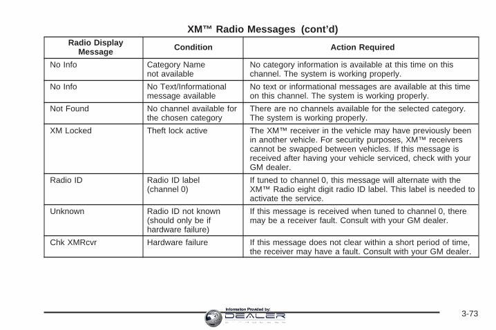
XM™ Radio Messages (cont’d)Radio Display
Message Condition Action Required
No Info Category Namenot available
No category information is available at this time on thischannel. The system is working properly.
No Info No Text/Informationalmessage available
No text or informational messages are available at this timeon this channel. The system is working properly.
Not Found No channel available forthe chosen category
There are no channels available for the selected category.The system is working properly.
XM Locked Theft lock active The XM™ receiver in the vehicle may have previously beenin another vehicle. For security purposes, XM™ receiverscannot be swapped between vehicles. If this message isreceived after having your vehicle serviced, check with yourGM dealer.
Radio ID Radio ID label(channel 0)
If tuned to channel 0, this message will alternate with theXM™ Radio eight digit radio ID label. This label is needed toactivate the service.
Unknown Radio ID not known(should only be ifhardware failure)
If this message is received when tuned to channel 0, theremay be a receiver fault. Consult with your GM dealer.
Chk XMRcvr Hardware failure If this message does not clear within a short period of time,the receiver may have a fault. Consult with your GM dealer.
3-73Information Provided by:

Playing a Cassette TapeThe tape player is built to work best with tapes that areup to 30 to 45 minutes long on each side. Tapeslonger than that are so thin they may not work well inthis player. The longer side with the tape visible shouldface to the right. If you hear nothing or hear a garbledsound, the tape may not be in squarely. Press the ejectbutton to remove the tape and start over.
If the ignition and radio are off, the tape can be inserted,but will not play until the ignition and radio are on.If the ignition is on and the radio is off, the tape can beinserted and will begin playing.
While the tape is playing, use the VOL, AUDIO, andSEEK controls just as you do for the radio. The cassettetape symbol will appear on the display and an arrowshowing which side of the tape is playing. The tapeplayer will play the other side of the tape when itreaches the end.
Cassette tape adapter kits for portable CD players willwork in the cassette tape player. See “CD Adapter Kits”later for more information.
The tape bias is set automatically when a metal orchrome tape is inserted.
If an error appears on the display, see “Cassette TapeMessages” later in this section.
1 PREV (Previous): The tape must have at leastthree seconds of silence between each selection forprevious to work. Press this pushbutton to go tothe previous selection on the tape if the current selectionhas been playing for less than three seconds. If pressedwhen the current selection has been playing fromthree to 13 seconds, it will go to the beginning of theprevious selection or the beginning of the currentselection, depending on the position on the tape.If pressed when the current selection has been playingfor more than 13 seconds, it will go to the beginningof the current selection.
SEEK and a negative number will appear on the displaywhile the cassette player is in the previous mode.Pressing this pushbutton multiple times will increase thenumber of selections to be searched back, up to −9.
2 NEXT: The tape must have at least three seconds ofsilence between each selection for next to work.Press this pushbutton to go to the next selection on thetape. Pressing this pushbutton multiple times, in nextmode, will increase the number of selections to besearched forward. SEEK and a positive numberwill appear on the display.
3-74Information Provided by:

3 REV (Reverse): Press this pushbutton to quicklyreverse the tape. The radio will play while the tapereverses. Press it again to return to playing speed.The station frequency and REV will appear on thedisplay. Select stations during reverse operation byusing TUNE and SEEK.
4 FWD (Forward): Press this pushbutton to quicklyadvance the tape. The radio will play while thetape advances. Press this pushbutton again to return toplaying speed. The station frequency and FWD willappear on the display. Select stations during forwardoperation by using TUNE and SEEK.
5 X SIDE: Press this pushbutton to play the other sideof the tape.
© SEEK ¨: The right arrow is the same as theNEXT pushbutton, and the left arrow is the same as thePREV pushbutton. If either arrow is held or pressedmore than once, the player will continue moving forwardor backward through the tape. SEEK and a positiveor negative number will appear on the display.
© SCAN ¨: Press and hold either the SCAN or theTYPE arrows for more than two seconds until SCANappears on the display and you hear a beep. The radiowill go to the next selection, play for 10 seconds,then go on to the next selection. Press either the SCANor the TYPE arrows again, to stop scanning. The tapemust have at least three seconds of silence betweeneach selection for scan to work.
BAND: Press this button to listen to the radio when acassette tape or CD is playing. The inactive tape or CDwill remain safely inside the radio for future listening.
TAPE DISC: Press this button to play a cassette tape orCD when listening to the radio. The inactive tape orCD will remain safely inside the radio for future listening.
Z (Eject): Press this button to stop and eject atape when it is playing or to eject a tape when it is notplaying. Eject may be activated with the radio off.
3-75Information Provided by:

Cassette Tape MessagesCHK TAPE (Check Tape): If this message appears onthe display, the tape will not play due to one of thefollowing errors:• The tape is tight and the player cannot turn the
tape hubs. Remove the tape. Hold the tape withthe open end down and try to turn the righthub counterclockwise with a pencil. Turn the tapeover and repeat. If the hubs do not turn easily,the tape may be damaged and should not be usedin the player. Try a new tape to make sure yourplayer is working properly.
• The tape is broken. Try a new tape.• The tape is wrapped around the tape head.
Attempt to get the cassette out. Try a new tape.
CLEAN: If this message appears on the display, thecassette tape player needs to be cleaned. It will still playtapes, but it should be cleaned as soon as possible toprevent damage to the tapes and player. See Careof the Cassette Tape Player on page 3-100.
If the cassette tape is not playing correctly, for any otherreason, try a known good cassette.
If any error occurs repeatedly or if an error cannot becorrected, contact your GM dealer. If the radio displaysan error message, write it down and provide it toyour GM dealer when reporting the problem.
CD Adapter KitsIt is possible to use a portable CD player with thecassette tape player after activating the bypass featureon your tape player.
To activate the bypass feature, perform thefollowing steps:
1. Turn the ignition on.
2. Turn the radio off.
3. Press and hold the TAPE DISC button forfive seconds. READY will appear on the display andthe tape symbol on the display will flash, indicatingthe feature is active.
4. Insert the adapter into the cassette tape slot. It willpower up the radio and begin playing.
The override feature will remain active until the ejectbutton is pressed.
Playing a CDInsert a CD partway into the slot, label side up.The player will pull it in and the CD should begin playing.If you want to insert a CD with the ignition off, firstpress the eject button or the INFO knob.
3-76Information Provided by:

If the ignition or radio is turned off with the CD in theplayer, it will stay in the player. When the ignitionor radio is turned on, the CD will start playing where itstopped, if it was the last selected audio source.
When a CD is inserted, the CD symbol will appear onthe display. As each new track starts to play, thetrack number will appear on the display.
The CD player can play the smaller 3 inch (8 cm)single CDs with an adapter ring. Full-size CDs and thesmaller CDs are loaded in the same manner.
If playing a CD-R, the sound quality may be reduceddue to CD-R quality, the method of recording, the qualityof the music that has been recorded, and the way theCD-R has been handled. There may be an increasein skipping, difficulty in finding tracks, and/or difficulty inloading and ejecting. If these problems occur, checkthe bottom surface of the CD. If the surface of the CD isdamaged, such as cracked, broken, or scratched, theCD will not play properly. If the surface of the CDis soiled, see Care of Your CDs and DVDs onpage 3-101 for more information.
If there is no apparent damage, try a known good CD.
Do not add any label to a CD, it could get caught in theCD player. If a CD is recorded on a personal computerand a description label is needed, try labeling the top ofthe recorded CD with a marking pen instead.
Notice: If you add any label to a CD, insert morethan one CD into the slot at a time, or attemptto play scratched or damaged CDs, you coulddamage the CD player. When using the CD player,use only CDs in good condition without anylabel, load one CD at a time, and keep the CD playerand the loading slot free of foreign materials,liquids, and debris.
If an error appears on the display, see “CD Messages”later in this section.
1 PREV (Previous): Press this pushbutton to goto the beginning of the current track if more thaneight seconds have played. TRACK and the tracknumber will appear on the display. If this pushbutton isheld or pressed more than once, the player willcontinue moving backward through the CD.
2 NEXT: Press this pushbutton to go to the next track.TRACK and the track number will appear on thedisplay. If this pushbutton is held or pressed more thanonce, the player will continue moving forward throughthe CD.
3-77Information Provided by:

3 REV (Reverse): Press and hold this pushbutton toquickly reverse within a track. Press and hold thispushbutton for less than two seconds to reverse atsix times the normal playing speed. Press and hold it formore than two seconds to reverse at 17 times thenormal playing speed. Release this pushbutton to playthe passage. ET and the elapsed time of the trackwill appear on the display.
4 FWD (Forward): Press and hold this pushbutton toquickly advance within a track. Press and hold thispushbutton for less than two seconds to advance atsix times the normal playing speed. Press and hold it formore than two seconds to advance at 17 times thenormal playing speed. Release this pushbutton to playthe passage. ET and the elapsed time of the trackwill appear on the display.
6 RDM (Random): Press this pushbutton to hear thetracks in random, rather than sequential, order. RDM ONwill appear on the display. RDM T and the tracknumber will appear on the display when each trackstarts to play. Press this pushbutton again to turnoff random play. RDM OFF will appear on the display.
© SEEK ¨: Press the left arrow to go to the startof the current or to the previous track. Press theright arrow to go to the start of the next track. If eitherarrow is held or pressed more than once, the player willcontinue moving backward or forward through the CD.
© SCAN ¨: Press and hold either the SCAN or theTYPE arrows for more than two seconds until SCANappears on the display and you hear a beep. The radiowill go to the next track, play for 10 seconds, then goon to the next track. Press either the SCAN or the TYPEarrows again, to stop scanning.
INFO (Information): Press this knob to see how longthe current track has been playing. ET and the elapsedtime will appear on the display. To change the defaulton the display, track or elapsed time, press theknob until you see the display you want, then holdthe knob for two seconds. The radio will produceone beep and the selected display will now bethe default.
BAND: Press this button to listen to the radio when acassette tape or CD is playing. The inactive tape or CDwill remain safely inside the radio for future listening.
TAPE DISC: Press this button to play a cassette tape orCD when listening to the radio. The inactive tape orCD will remain safely inside the radio forfuture listening.
Z (Eject): Press this button to stop and eject a CDwhen it is playing or to eject a CD when it is not playing.Eject may be activated with either the ignition or radiooff. CDs may be loaded with the radio and ignition off ifthis button is pressed first.
3-78Information Provided by:

CD MessagesIf the CD comes out, it could be for one of the followingreasons:
• It is very hot. When the temperature returns tonormal, the CD should play.
• You are driving on a very rough road. When theroad becomes smoother, the CD should play.
• The CD is dirty, scratched, wet, or upside down.
• The air is very humid. If so, wait about an hour andtry again.
• There may have been a problem while burningthe CD.
• The label may be caught in the CD player.
If the CD is not playing correctly, for any other reason,try a known good CD.
If any error occurs repeatedly or if an error cannot becorrected, contact your GM dealer. If the radio displaysan error message, write it down and provide it toyour GM dealer when reporting the problem.
Listening to a DVDIf your vehicle has the Rear Seat Entertainment (RSE)system and a DVD is playing, the DVD symbol willappear on the radio display indicating that the DVDis available and can be listened to through yourvehicle’s speakers.
To listen to the DVD, press the TAPE DISC button untilRSE appears on the radio display. The current radiosource will stop and the DVD sound will come throughthe speakers.
To stop listening to the DVD, press the TAPE DISCbutton, if a cassette tape or a CD is loaded, or press theBAND button to select a different source.
When the RSE system is turned off, the DVD symbolwill go off of the radio display and the radio will displayRSE OFF. The radio will return to the last radiosource that you were listening to.
See Rear Seat Entertainment System on page 3-80 formore information.
3-79Information Provided by:

Navigation/Radio SystemYour vehicle may have a navigation radio system.The navigation system has built-in features intended tominimize driver distraction. Technology alone, nomatter how advanced, can never replace your ownjudgment. See the navigation system manual for sometips to help you reduce distractions while driving.
Rear Seat Entertainment SystemYour vehicle may have a DVD Rear Seat Entertainment(RSE) system. The RSE system includes a DVDplayer, a video display screen, two sets of wirelessheadphones, and a remote control.
Parental ControlThis button is located behind the video screen. Press thisbutton while a DVD or CD is playing to freeze the videoand mute the audio. The video screen will displayParental Control ON and the power indicator light on theDVD player will flash. It will also disable all other buttonoperations from the remote control and the DVD player,with the exception of the eject button. Press this buttonagain to restore operation of the DVD player.This button may also be used to turn the DVD playerpower on and automatically resume play if the ignition isin RUN, ACCESSORY, or if RAP is active.
Before You DriveThe RSE system is for rear seat passengers only.The driver cannot safely view the video screen whiledriving and should not try to do so.
HeadphonesThe RSE system includes two sets of wirelessheadphones.Each set of headphones has an ON/OFF control.An indicator light will illuminate on the headphoneswhen they are on. If the light does not illuminate, thebatteries may need to be replaced. See “BatteryReplacement” following for more information.Each set of headphones has a volume knob. To adjustthe volume, adjust this knob.The transmitters are located below the video displayscreen. The headphones will shut off automaticallyif they lose the signal from the system after aboutfour minutes to save battery power. The signal may belost if the system is turned off or if the headphonesare out of range of the transmitters.When using the wired headphones, if the front seatpassengers play a CD in the Radio with Six-Disc CD(if equipped) or use XM™ Satellite Radio Service(if equipped), you will hear the audio for these sources,instead of the DVD or CD that is currently playingthrough the RSE.
3-80Information Provided by:

Notice: Do not store the headphones in heat ordirect sunlight. This could damage the headphonesand repairs will not be covered by your warranty.Keep the headphones stored in a cool, dry place.Both sets of rear seat headphones may include foam earpads that can be replaced.Foam ear pads on these headphones may becomeworn or damaged. The headphone foam ear pads canbecome damaged if they are not handled or storedproperly. If the foam ear pads do become damaged orworn out, the pads can be replaced separately fromthe headphone set. It is not necessary to replacethe complete headphone set.The headphone replacement foam ear pads can beordered in pairs. See your dealer for more information.
Battery ReplacementTo change the batteries, do the following:
1. Loosen the screw on the battery compartment doorlocated on the left side of the headphone earpiece.
2. Replace the two AAA batteries in the compartment.Make sure that they are installed correctly, usingthe diagram on the inside of the batterycompartment.
3. Tighten the screw to close the compartment door.If the headphones are to be stored for a long periodof time, remove the batteries and keep them in a cool,dry place.
Stereo RCA JacksThe RCA jacks are located behind the video screen.The RCA jacks allow audio and video signals tobe connected from an auxiliary device such as acamcorder or a video game unit to the RSE system.Standard RCA cables, not included, are neededto connect the auxiliary device to the RCA jacks. Theyellow connector inputs video and the red and whiteconnectors input right and left audio. Refer to themanufacturer’s instructions for proper connection of theauxiliary device.
To use the auxiliary inputs on the RSE system, connectan external auxiliary device to the color-coded RCAjacks and turn both the auxiliary device and theRSE system power on. If the RSE system had beenpreviously in the DVD player mode, pressing the SRCEbutton on the faceplate or the remote control willswitch the RSE system between the auxiliary deviceand the DVD player.
3-81Information Provided by:

How to Change the Video Format when inthe Auxiliary ModeThe auxiliary input video format is preset to NTSC.In some countries, the video format may be in thePAL system. To change the video format, perform thefollowing:
1. Press the display menu button.
2. Press the down arrow button to highlight the VideoFormat option.
3. Press the enter button to select Video Format.
4. Press the right or left arrow button to selectthe desired video format.
5. Press the enter button to accept the change.
Audio OutputAudio from the DVD player or auxiliary inputs may beheard through the following possible sources:
• Wireless Headphones
• Vehicle Speakers
• Vehicle wired headphone jacks on the Rear SeatAudio system (if equipped)
The RSE system will always transmit the audio signalby infrared to the wireless headphones, if there is audioavailable. See “Headphones” previously for moreinformation.
The RSE system is capable of outputting audio to thevehicle speakers by using the radio. The RSE systemmay be selected as an audio source on the radio ifthe RSE system power is on. Once the RSE system isselected as an audio source on the radio, adjust thespeaker volume on the radio, if necessary. If the RSEsystem power is not on, the RSE system will not bean available source on the radio. Refer to the radioinformation for the radio that your vehicle has for moreinformation.
The RSE system is capable of outputting audio to thewired headphone jacks on the rear seat audio system(if equipped). The RSE system may be selected asan audio source on the rear seat audio system ifthe RSE system power is on. Refer to Rear SeatAudio (RSA) on page 3-92 for more information.
3-82Information Provided by:

Video ScreenThe video screen is located in the overhead console.To use the video screen, push forward on the releaselatch and the screen will fold down. Adjust the screen’sposition as desired. When the video screen is not inuse, push it up into its latched position.
The DVD player and display will continue to operatewhen the screen is in the up or the down position.The video screen contains the transmitters for thewireless headphones and the remote control. If thescreen is in the closed position, the signals will not beavailable for the operation of the headphones orthe remote control.
Notice: Avoid directly touching the video screen,as damage may occur. See “Cleaning the VideoScreen” later in this section for more information.
DVD PlayerThe DVD player is located in the overhead console.The DVD player can be controlled by the buttons onthe DVD player and/or by the buttons on the remotecontrol. See “Remote Control” later in this sectionfor more information.
The DVD player power may be turned on when theignition is in RUN, ACCESSORY, or when RetainedAccessory Power (RAP) is active.
The RSE system DVD player is only compatible withDVDs of the appropriate region code for the country thatthe vehicle was sold in. The DVD region code isprinted on the jacket of most DVDs.
Standard audio CDs, CD-R, CD-RW, Video CD andPhoto CD/CD-R media are fully supported by this DVDplayer. DVD-R and DVD-RW media is supported ifformatted as DVD-Video. DVD+R and DVD+RW mediamay or may not be supported by the DVD player.The DVD player does not support DVD-RAM,DVD-ROM, and DVD Audio media. An error messagewill appear on the display if this type of media is insertedinto the DVD player.
3-83Information Provided by:

When using the wired headphones, not included, if thefront seat passengers play a CD in the Radio withSix-Disc CD (if equipped) or use XM™ Satellite RadioService (if equipped), you will hear the audio forthese sources, instead of the DVD or CD that is currentlyplaying through the RSE.
If an error message appears on the video screen, see“DVD Messages” later in this section.
DVD Player ButtonsO(Power): Press this button to turn the RSE systemon and off. The power indicator light will illuminatewhen the power is on.
X (Eject): Press this button to eject a DVD or CD.
SRCE (Source): Press this button to switch betweenthe DVD player and an auxiliary source.
c(Stop): Press this button to stop playing, rewinding,or fast forwarding a DVD or CD. Press this buttontwice to return to the beginning of the DVD.
s (Play/Pause): Press this button to start play of aDVD or CD. Press this button while a DVD or CD isplaying to pause it. Press this button again to continuethe play of the DVD or CD.
y (Main DVD Menu): Press this button to access theDVD menu. The DVD menu is different on everyDVD. Use the up, down, left, and right arrow buttons tomove the cursor around the DVD menu. After makinga selection press the enter button. This button onlyoperates when playing a DVD.
z (Set-up Menu): Press this button to adjust thecolor, tint, brightness, contrast, display mode, anddynamic range compression. The dynamic rangecompression feature can be used to reduce loud audioand increase low audio produced by some DVDs.
3-84Information Provided by:

To change a feature back to the factory default setting,press this button to display the feature, then pressand hold this button. The default setting will appear onthe display.
While playing an Audio or DVD disc, press andhold this button to display and to remove the trackand time information.
n, q, p, o (Menu Navigation Arrows): Use thearrow buttons to navigate through a menu.
r (Enter): Press this button to select the choicesthat are highlighted in any menu.
Playing a DiscTo play a disc, gently insert the disc with the labelside up into the loading slot. The DVD player willcontinue loading the disc and the player willautomatically start, if the vehicle is in RUN,ACCESSORY, or when RAP is active.
If a disc is already in the player, press the play/pausebutton on the DVD player faceplate or on the remotecontrol.
Some DVDs will not allow fast forwarding or skipping ofthe copyright information or the previews. SomeDVDs will begin playing after the previews have finished.If the DVD does not begin to play the main title, referto the on-screen instructions.
Stopping and Resuming PlaybackTo stop playing a disc, press and release the stopbutton on the DVD player faceplate or the remote control.
To resume playback, press the play/pause button onthe DVD player faceplate or the remote control.The movie should resume play from where it was laststopped, if the disc has not been ejected and thestop button has not been pressed twice. If the disc hasbeen ejected or if the stop button has been pressedtwice, the disc will resume play at the beginning.
Ejecting a DiscPress the eject button on the DVD player faceplateto eject the disc. There is not an eject button onthe remote control.
If a disc is ejected from the player, but is not removed,the DVD player will reload the disc after a short period oftime. The disc will be stored in the DVD player. The DVDplayer will not resume play of the disc automatically.
3-85Information Provided by:

Remote ControlTo use the remote control, aim it at the transmitterwindow below the video screen and press the desiredbutton. Direct sunlight or very bright light may affect theability of the RSE system to receive signals from theremote control. If the remote control does not seem tobe working, the batteries may need to be replaced.See “Battery Replacement” later in this section.
Objects blocking the line of sight may also affect thefunction of the remote control.
Notice: Storing the remote control in a hot area orin direct sunlight may damage it, and the repairswill not be covered by your warranty. Keep theremote control stored in a cool, dry place.
To extend the life of the batteries, the remote controldoes not have a press and hold feature.
Remote Control Buttons
O (Power): Press this button to turn the DVD playeron and off.
v (Title): Press this button to return the DVD to themain menu of the DVD.
n, q, p, o (Menu Navigation Arrows): Use thearrow buttons to navigate through a menu.
3-86Information Provided by:

z (Set-up Menu): Press this button to adjust thecolor, tint, brightness, contrast, display mode, anddynamic range compression. The dynamic rangecompression feature can be used to reduce loud audioand increase low audio produced by some DVDs.
e (Audio): Press this button to display a menu thatwill only appear when a DVD is being played. The formatand content of this function will vary for each disc.
r (Fast Reverse): Press this button to fast reversethe DVD or CD. To stop fast reversing, press this buttonagain. This button may not work when the DVD isplaying the copyright information or the previews.
SRCE (Source): Press this button to switch betweenthe DVD player and an auxiliary source.
c (Stop): Press this button to stop playing, rewinding,or fast forwarding a DVD or CD. Press this buttontwice to return to the beginning of the DVD.
t (Previous Track/Chapter): Press this button toreturn to the start of the current track or chapter. Pressthis button again to return to the previous track orchapter. This button may not work when the DVD isplaying the copyright information or the previews.
1 through 0 (Numeric Keypad): The numeric keypadprovides you with the capability of direct chapter,title, and track number selection.
}10 (Double Digit Entries): Press this button toselect chapter, title, and track numbers greater than 9.Press this button before inputting the number.
\ (Clear): Press this button within three seconds afterinputting a number to clear the number(s).
P (Illumination): Press this button to turn the remotecontrol backlight on. The backlight will time out afterabout 7 to 10 seconds if no other button is pressed whilethe backlight is on.
y (Main DVD Menu): Press this button to access theDVD menu. The DVD menu is different on everyDVD. Use the up, down, left, and right arrow buttons tomove the cursor around the DVD menu. After makinga selection press the enter button. This button onlyoperates when playing a DVD.
r (Enter): Press this button to select the choicesthat are highlighted in any menu.
3-87Information Provided by:
q (Return): Press this button to exit the currentactive menu and return to the previous menu. Thisbutton will operate only when a DVD is playing and amenu is active.
| (Camera Angle): Press this button to changecamera angles on DVDs that have this feature when aDVD is playing. The format and content of thisfunction will vary for each disc.
{ (Subtitle): Press this button to turn on subtitles andto move through subtitle options when a DVD isplaying. The format and content of this function will varyfor each disc.
[ (Fast Forward): Press this button to fast forwardthe DVD or CD. To stop fast forwarding, press thisbutton again. This button may not work when the DVDis playing the copyright information or the previews.
s (Play/Pause): Press this button to start play of aDVD or CD. Press this button while a DVD or CD isplaying to pause it. Press this button again to continuethe play of the DVD or CD.
When the DVD is playing, press the pause button thenpress the fast forward button. The DVD will continueplaying in a slow play mode. To cancel slow play mode,press the play/pause button.
u (Next Track/Chapter): Press this button to advanceto the beginning of the next track or chapter. Thisbutton may not work when the DVD is playing thecopyright information or the previews.
Battery ReplacementTo change the batteries, do the following:
1. Remove the battery compartment door located onthe bottom of the remote control.
2. Replace the two AA batteries in the compartment.Make sure that they are installed correctly, usingthe diagram on the inside of the batterycompartment.
3. Close the battery door securely.
If the remote control is to be stored for a long period oftime, remove the batteries and keep them in a cool,dry place.
3-88Information Provided by:

Problem Recommended ActionNo power. The ignition might not be
in on or accessory.The parental controlbutton might have beenturned on. The powerindicator light will flash.
Disc will not play. The system might be off.The parental controlbutton might have beenturned on. The powerindicator light will flash.The system might be inauxiliary mode.The disc is upside downor is not compatible.
The picture does not fillthe screen. There areblack borders on thetop and bottom or onboth sides or it looksstretched out.
Check the displaymode settings in thedisplay menu.
The disc was ejected, butit was pulled back intothe DVD player.
The disc is being storedin the DVD player. Pressthe eject button again toeject the disc.
Problem Recommended ActionIn auxiliary mode, thepicture moves or scrolls.
Check the auxiliaryinput connections atboth devices.Change the VideoFormat to PAL or NTSC.See “Stereo RCA Jacks”previously for how tochange the video format.
The language in theaudio or on the screenis wrong.
Check the audio orlanguage selection in themain DVD menu.
The remote control doesnot work.
Check to make surethere is no obstructionbetween the remotecontrol and thetransmitter window.Check the batteries tomake sure they are notdead or installedincorrectly.The parental controlbutton might have beenturned on. The powerindicator light will flash.
3-89Information Provided by:

Problem Recommended ActionAfter stopping the player,I push Play butsometimes the DVDstarts where I left offand sometimes atthe beginning.
If the stop button waspressed one time, theDVD player will resumeplaying where the DVDwas stopped. If the stopbutton was pressedtwo times the DVD playerwill begin to play from thebeginning of the DVD.
The auxiliary source isrunning but there is nopicture or sound.
Check that the DVDplayer is in the auxiliarysource mode.Check the auxiliaryinput connections atboth devices.
My disc is stuck in theplayer. The Load/Ejectbutton does not work.
Turn the DVD power off,then on, then press theload/eject button on theDVD player.Do not attempt to forciblyremove the disc from theDVD player. This couldpermanently damage thedisc and DVD player.
Problem Recommended ActionSometimes the wirelessheadphone audio cutsout or buzzes.
Check for obstructions,low batteries, receptionrange, and interferencefrom cellular telephonetowers or by using yourcellular telephone inthe vehicle.Check that theheadphones are facingthe front of the vehicle.
I lost the remote and/orthe headphones.
See your dealerfor assistance.
The DVD is playing,but there is no pictureor sound.
Check that the DVDplayer is in DVD mode.
The audio/video skipsor jumps.
The DVD or CD couldbe dirty, scratched,or damaged.
The audio from the radiofor the Radio withSix-Disc CD and XM™has taken over the audiofrom the DVD or CDwhen using the wiredheadphones.
The RSE isworking correctly.Use the wirelessheadphones or havethe front seatpassengers listen toanother audio source.
3-90Information Provided by:

DVD MessagesThe following errors may be displayed on thevideo screen:
Disc Format Error: This message will be displayed if adisc is inserted upside down, if the disc is not readable,or if the format is not compatible with the DVD player.
Load/Eject Error: This message will be displayed if thedisc is not properly loaded or ejected.
Disc Play Error: This message will be displayed if theDVD player cannot play the disc. Scratched ordamaged discs will cause this error.
Region Code Error: This message will be displayed ifthe region code of the DVD is not compatible withthe region code of the DVD player.
No Disc: This message will be displayed if any of thebuttons on the DVD faceplate or remote control arepressed and no disc is present in the DVD player.
DVD DistortionThere may be an experience with audio distortion in thewireless headphones when operating cellular phones,scanners, CB radios, Global Positioning Systems (GPS)*,two-way radios, mobile fax, or walkie talkies.
It may be necessary to turn off the DVD player whenoperating one of these devices in or near the vehicle.
* Excludes the OnStar® System.
Cleaning the Video ScreenPour some isopropyl or rubbing alcohol on a clean clothand gently wipe the video screen. Do not spraydirectly onto the screen and do not press too hard ortoo long on the video screen.
3-91Information Provided by:

Rear Seat Audio (RSA)This feature allows rear seat passengers to listen to anyof the sources: radio, cassette tapes, CDs, or DVDs.However, the rear seat passengers can only control thesources that the front seat passengers are notlistening to. For example, rear seat passengers maylisten to and control CDs or DVDs through theheadphones while the driver listens to the radio throughthe front speakers. The rear seat passengers havecontrol of the volume for each set of headphones.
The front seat audio controls always have priority overthe RSA controls. If the front seat passengers switch thesource for the main radio to a remote source, the RSA willnot be able to control the source. You can operate therear seat audio when the main radio is off.
P (Power): Press this button to turn the system on oroff. The rear speakers will be muted when the poweris turned on unless your vehicle is equipped withthe Bose® audio system.
3-92Information Provided by:
u (Volume): Turn this knob to increase or todecrease the volume. The left knob controls the leftheadphones and the right knob controls the rightheadphones.
SRC (Source): Press this button to select a source:radio, CDs, or DVDs.
x SEEK w: When listening to FM1, FM2, or AM,press the up or the down arrow to go to the next or to theprevious station and stay there. This function is inactive ifthe front seat passengers are listening to the radio.
When a cassette is playing, press the up or the downarrow to go to the next or the previous selection. Thisfunction is inactive if the front seat passengers arelistening to a cassette tape.
When a CD is playing, press the up arrow to go to thenext track on the CD. Press the down arrow to go to thestart of the current track if more than eight seconds haveplayed. This function is inactive if the front seatpassengers are listening to a CD.
PROG (Program): Press this button to go to the nextpreset radio station set on the pushbuttons on themain radio. This function is inactive if the front seatpassengers are listening to the radio.
When a cassette tape is playing, press this buttonto go to the other side of the tape. This functionis inactive if the front seat passengers are listeningto a cassette tape.
When a CD is playing, press this button to go to thebeginning of the CD. This function is inactive if the frontseat passengers are listening to a CD.
When a CD is playing in the six-disc CD changer, pressthis button to select the next CD, if multiple CDs areloaded. This function is inactive if the front seatpassengers are listening to a CD.
3-93Information Provided by:

CD Changer
The CD changer plays up to six standard size CDscontinuously. Individual CDs may be loaded or ejectedinto or from any position.
An amber light on each numbered button indicates aCD is loaded in the respective position. A green light ona numbered button indicates that a CD is playing.When loading CDs, the loading slot indicators turn greento indicate that the player is ready to accept a CD.CDs can be loaded or ejected with the radio orthe ignition off.
You must load CDs with the label side up. If you do not,the player will automatically eject the CDs.
Notice: Loading CDs with adhesive labels willdamage the player.
To load a CD, perform the following steps:1. Press the LOAD button. Available positions will
blink green.2. Select a position by pressing the numbered button
with the green blinking light. If a button is notpressed within five seconds, the changer will go tothe lowest available position.
3. Load the CD when the loading slot indicators turngreen. An internal door will open allowing a singleCD to be inserted into the changer. Afterapproximately 10 seconds the changer will beready to play.
3-94Information Provided by:

To load two or more CDs, perform the following steps:
1. Press and hold the LOAD button. The firstCD will be loaded into the lowest numberedempty position.
2. Load a single CD when the loading slot indicatorsturn green. After about 10 seconds the changer willcycle to the next available position.
3. Repeat Step 2 until all CDs are loaded into all ofthe desired positions. If you do not wish to load allof the positions, cancel loading by pressing andreleasing the load button or wait 25 seconds for thechanger to time out.
To eject a single CD, perform the following steps:
1. Press the eject button (upward pointing arrow).The buttons with loaded CDs will blink green.
2. Press one of the green blinking buttons toselect the location of the CD you want to eject.The changer will move to that location and eject theCD. If you do not remove the CD from the playerwithin 25 seconds, it will be reloaded. If theeject button is pressed and a numbered locationbutton is not pressed within five seconds, thecurrent or last played CD will be ejected.
To eject all CDs, press and hold the eject button.
To play a CD, perform one of the following:
• With the radio on, press the numbered button withan amber indicator light on the CD changer.
• Press the TAPE CD button on the radio. The CDchanger will go to its last played position.
3-95Information Provided by:
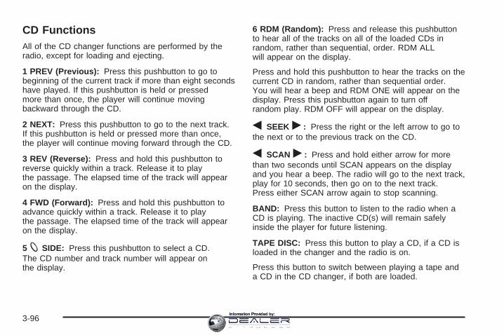
CD FunctionsAll of the CD changer functions are performed by theradio, except for loading and ejecting.
1 PREV (Previous): Press this pushbutton to go tobeginning of the current track if more than eight secondshave played. If this pushbutton is held or pressedmore than once, the player will continue movingbackward through the CD.
2 NEXT: Press this pushbutton to go to the next track.If this pushbutton is held or pressed more than once,the player will continue moving forward through the CD.
3 REV (Reverse): Press and hold this pushbutton toreverse quickly within a track. Release it to playthe passage. The elapsed time of the track will appearon the display.
4 FWD (Forward): Press and hold this pushbutton toadvance quickly within a track. Release it to playthe passage. The elapsed time of the track will appearon the display.
5 X SIDE: Press this pushbutton to select a CD.The CD number and track number will appear onthe display.
6 RDM (Random): Press and release this pushbuttonto hear all of the tracks on all of the loaded CDs inrandom, rather than sequential, order. RDM ALLwill appear on the display.
Press and hold this pushbutton to hear the tracks on thecurrent CD in random, rather than sequential order.You will hear a beep and RDM ONE will appear on thedisplay. Press this pushbutton again to turn offrandom play. RDM OFF will appear on the display.
q SEEK r: Press the right or the left arrow to go tothe next or to the previous track on the CD.
q SCAN r: Press and hold either arrow for morethan two seconds until SCAN appears on the displayand you hear a beep. The radio will go to the next track,play for 10 seconds, then go on to the next track.Press either SCAN arrow again to stop scanning.
BAND: Press this button to listen to the radio when aCD is playing. The inactive CD(s) will remain safelyinside the player for future listening.
TAPE DISC: Press this button to play a CD, if a CD isloaded in the changer and the radio is on.
Press this button to switch between playing a tape anda CD in the CD changer, if both are loaded.
3-96Information Provided by:

CD Changer Errors
CHK CD (Check): If this message appears on thedisplay, it could be for one of the following reasons:
• It is very hot. When the temperature returns tonormal, the CD should play.
• You are driving on a very rough road. When theroad becomes smoother, the CD should play.
• The CD is dirty, scratched, wet, or upside down.
• The air is very humid. If so, wait about an hour andtry again.
• There may have been a problem while burningthe CD.
• The label may be caught in the CD player.
• The CD player is very hot.
Notice: If you add any label to a CD, insert morethan one CD into the slot at a time, or attemptto play scratched or damaged CDs, you coulddamage the CD player. When using the CD player,use only CDs in good condition without anylabel, load one CD at a time, and keep the CD playerand the loading slot free of foreign materials,liquids, and debris.
If the CD is not playing correctly, for any other reason,try a known good CD.
If any error occurs repeatedly or if an error cannot becorrected, contact your GM dealer. If the radio displaysan error message, write it down and provide it toyour GM dealer when reporting the problem.
Theft-Deterrent FeatureTHEFTLOCK® is designed to discourage theft ofyour vehicle’s radio. The feature works automaticallyby learning a portion of the Vehicle IdentificationNumber (VIN). If the radio is moved to a differentvehicle, it will not operate and LOCKED will appear onthe display.
When the radio and vehicle are turned off, the blinkingred light indicates that THEFTLOCK® is armed.
With THEFTLOCK® activated, the radio will not operateif stolen.
3-97Information Provided by:

Audio Steering Wheel Controls
Some audio controls can be adjusted at the steeringwheel. They include the following:
g (OnStar ®/Mute): If your vehicle has OnStar, pressthis button to interact with the OnStar system. Seethe OnStar® System on page 2-46 in this manual formore information.
If your vehicle does not have OnStar, press this buttonto silence the system. Press it again, or any otherradio button, to turn on the sound.
PROG (Program): Press this button to play a stationyou have programmed on the radio preset pushbuttons.The radio will only seek preset stations with a strongsignal that are in the selected band.
When a CD is playing in the CD changer, press thisbutton to go to the next available CD, if multiple CDsare loaded.
Q SOURCE R: Press this button to switch betweenFM1, FM2, AM, or XM1 or XM2 (if equipped), or aCD. If a CD is loaded the CD symbol will appear onthe display.
Q SEEK R: Press the up or the down arrow to go tothe next or to the previous radio station and staythere. The radio will only seek stations with a strongsignal that are in the selected band.
When a CD is playing, press the up or the down arrowto fast forward or reverse.
Q VOL R (Volume): Press the up or the down arrowto increase or to decrease the volume.
3-98Information Provided by:

Radio ReceptionYou may experience frequency interference and staticduring normal radio reception if items such as cellphonechargers, vehicle convenience accessories, andexternal electronic devices are plugged into theaccessory power outlet. If there is interference or static,unplug the item from the accessory power outlet.
AMThe range for most AM stations is greater than for FM,especially at night. The longer range can causestation frequencies to interfere with each other. Forbetter radio reception, most AM radio stations will boostthe power levels during the day, and then reducethese levels during the night. Static can also occur whenthings like storms and power lines interfere with radioreception. When this happens, try reducing the treble onyour radio.
FM StereoFM stereo will give the best sound, but FM signals willreach only about 10 to 40 miles (16 to 65 km). Tallbuildings or hills can interfere with FM signals, causingthe sound to fade in and out.
XM™ Satellite Radio ServiceXM™ Satellite Radio Service gives digital radioreception from coast-to-coast in the 48 contiguousUnited States, and in Canada (if available). Just as withFM, tall buildings or hills can interfere with satelliteradio signals, causing the sound to fade in and out.In addition, traveling or standing under heavy foliage,bridges, garages, or tunnels may cause loss of theXM™ signal for a period of time. The radio may displayNO SIGNAL to indicate interference.
3-99Information Provided by:
Care of the Cassette Tape PlayerA tape player that is not cleaned regularly can causereduced sound quality, ruined cassettes, or a damagedmechanism. Cassette tapes should be stored in theircases away from contaminants, direct sunlight, andextreme heat. If they are not, they may not operateproperly or may cause failure of the tape player.
The tape player should be cleaned regularly after every50 hours of use. The radio may display CLEAN toindicate that the tape player has been used for 50 hourswithout resetting the tape clean timer. If this messageappears on the display, the cassette tape playerneeds to be cleaned. It will still play tapes, but it shouldbe cleaned as soon as possible to prevent damageto the tapes and player. If there is a reduction in soundquality, try a known good cassette to see if the tapeor the tape player is at fault. If this other cassette has noimprovement in sound quality, clean the tape player.
For best results, use a scrubbing action, non-abrasivecleaning cassette with pads which scrub the tapehead as the hubs of the cleaner cassette turn.The recommended cleaning cassette is availablethrough your dealer.
When cleaning the cassette tape player with therecommended non-abrasive cleaning cassette, it ispossible that the cassette may eject, because the cuttape detection feature on the radio may recognize it as abroken tape, in error. To prevent the cleaning cassettefrom being ejected, use the following steps:
1. Turn the ignition on.
2. Turn the radio off.
3. Press and hold the TAPE DISC button forfive seconds. READY will appear on the displayand the cassette symbol will flash for five seconds.
4. Insert the scrubbing action cleaning cassette.
5. Eject the cleaning cassette after the manufacturer’srecommended cleaning time.When the cleaning cassette has been ejected, thecut tape detection feature will be active again.
A non-scrubbing action, wet-type cleaner which uses acassette with a fabric belt to clean the tape headcan be used. This type of cleaning cassette will noteject on its own. A non-scrubbing action cleaner may notclean as thoroughly as the scrubbing type cleaner.The use of a non-scrubbing action, dry-type cleaningcassette is not recommended.
3-100Information Provided by:

After the player is cleaned, press and hold the ejectbutton for five seconds to reset the CLEAN indicator.The radio will display --- or CLEANED to show theindicator was reset.
Cassettes are subject to wear and the soundquality may degrade over time. Always make sure thecassette tape is in good condition before the tape playeris serviced.
Care of Your CDs and DVDsHandle CDs carefully. Store them in their original casesor other protective cases and away from directsunlight and dust. The CD player scans the bottomsurface of the disc. If the surface of a CD is damaged,such as cracked, broken, or scratched, the CD willnot play properly or not at all. If the surface of a CD issoiled, take a soft, lint free cloth or dampen a clean, softcloth in a mild, neutral detergent solution mixed withwater, and clean it. Make sure the wiping process startsfrom the center to the edge.
Do not touch the bottom side of a CD while handling it;this could damage the surface. Pick up CDs bygrasping the outer edges or the edge of the hole andthe outer edge.
Care of the CD and DVD PlayerThe use of CD lens cleaners for CDs is not advised,due to the risk of contaminating the lens of the CD opticswith lubricants internal to the CD mechanism.
Fixed Mast AntennaThe fixed mast antenna can withstand most car washeswithout being damaged. If the mast should everbecome slightly bent, straighten it out by hand. If themast is badly bent, replace it.
Check occasionally to make sure the mast is stilltightened to the cowl. If tightening is required,tighten by hand, then with a wrench one quarter turn.
3-101Information Provided by:

XM™ Satellite RadioAntenna SystemThe XM™ Satellite Radio antenna is located on the roofof your vehicle. Keep this antenna clear of snow andice build up for clear radio reception.
If your vehicle has a sunroof, the performance of theXM™ system may be affected if the sunroof is open.
Loading items onto the roof of your vehicle can interferewith the performance of the XM™ system. Make surethe XM™ Satellite Radio antenna is not obstructed.
Chime Level AdjustmentThe radio is used to adjust the vehicle’s chime level.To change the volume level of the chime, press and holdpushbutton 6 with the ignition on and the radio poweroff. The volume level will change from the normallevel to loud, and LOUD will appear on the radio display.To change back to the default or normal setting,press and hold pushbutton 6 again. The volume levelwill change from the loud level to normal, and NORMALwill appear on the radio display. Each time the chimevolume is changed, three chimes will sound as anexample of the new volume selected. Removing theradio and not replacing it with a factory radio or chimemodule will disable vehicle chimes.
3-102Information Provided by:

Your Driving, the Road, and Your Vehicle ..........4-2Defensive Driving ...........................................4-2Drunken Driving .............................................4-3Control of a Vehicle ........................................4-5Braking .........................................................4-6Anti-Lock Brake System (ABS) .........................4-7Braking in Emergencies ...................................4-8Road Sensing Suspension ...............................4-9StabiliTrak® System ........................................4-9All-Wheel Drive (AWD) System .......................4-12Steering ......................................................4-12Off-Road Recovery .......................................4-14Passing .......................................................4-14Loss of Control .............................................4-16Off-Road Driving ...........................................4-17Driving at Night ............................................4-30Driving in Rain and on Wet Roads ..................4-31
City Driving ..................................................4-33Freeway Driving ...........................................4-34Before Leaving on a Long Trip .......................4-35Highway Hypnosis ........................................4-35Hill and Mountain Roads ................................4-36Winter Driving ..............................................4-38If Your Vehicle is Stuck in Sand, Mud,
Ice or Snow ..............................................4-42Rocking Your Vehicle to Get It Out .................4-42Recovery Hooks ...........................................4-43Loading Your Vehicle ....................................4-44Truck-Camper Loading Information ..................4-49
Towing ..........................................................4-50Towing Your Vehicle .....................................4-50Recreational Vehicle Towing ...........................4-50Towing a Trailer ...........................................4-50Trailer Recommendations ...............................4-63
Section 4 Driving Your Vehicle
4-1Information Provided by:

Your Driving, the Road, andYour Vehicle
Defensive DrivingThe best advice anyone can give about driving is:Drive defensively.
Please start with a very important safety device in yourvehicle: Buckle up. See Safety Belts: They Are forEveryone on page 1-8.
{CAUTION:
Defensive driving really means “Be ready foranything.” On city streets, rural roads, orexpressways, it means “Always expect theunexpected.” Assume that pedestrians or otherdrivers are going to be careless and makemistakes. Anticipate what they might do andbe ready. Rear-end collisions are about themost preventable of accidents. Yet they arecommon. Allow enough following distance.Defensive driving requires that a driverconcentrate on the driving task. Anything thatdistracts from the driving task makes properdefensive driving more difficult and can evencause a collision, with resulting injury. Ask apassenger to help do these things, or pull offthe road in a safe place to do them. Thesesimple defensive driving techniques couldsave your life.
4-2Information Provided by:

Drunken DrivingDeath and injury associated with drinking and driving isa national tragedy. It is the number one contributorto the highway death toll, claiming thousands of victimsevery year.
Alcohol affects four things that anyone needs to drivea vehicle:
• Judgment
• Muscular Coordination
• Vision
• Attentiveness
Police records show that almost half of all motorvehicle-related deaths involve alcohol. In most cases,these deaths are the result of someone who wasdrinking and driving. In recent years, more than16,000 annual motor vehicle-related deaths have beenassociated with the use of alcohol, with more than300,000 people injured.
Many adults — by some estimates, nearly half the adultpopulation — choose never to drink alcohol, so theynever drive after drinking. For persons under 21,it is against the law in every U.S. state to drink alcohol.There are good medical, psychological, anddevelopmental reasons for these laws.
The obvious way to eliminate the leading highwaysafety problem is for people never to drink alcoholand then drive. But what if people do? How much is“too much” if someone plans to drive? It is a lot less thanmany might think. Although it depends on each personand situation, here is some general information onthe problem.
The Blood Alcohol Concentration (BAC) of someonewho is drinking depends upon four things:
• The amount of alcohol consumed
• The drinker’s body weight
• The amount of food that is consumed before andduring drinking
• The length of time it has taken the drinker toconsume the alcohol
4-3Information Provided by:
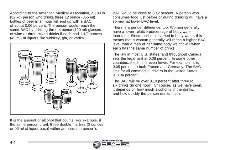
According to the American Medical Association, a 180 lb(82 kg) person who drinks three 12 ounce (355 ml)bottles of beer in an hour will end up with a BACof about 0.06 percent. The person would reach thesame BAC by drinking three 4 ounce (120 ml) glassesof wine or three mixed drinks if each had 1-1/2 ounces(45 ml) of liquors like whiskey, gin, or vodka.
It is the amount of alcohol that counts. For example, ifthe same person drank three double martinis (3 ouncesor 90 ml of liquor each) within an hour, the person’s
BAC would be close to 0.12 percent. A person whoconsumes food just before or during drinking will have asomewhat lower BAC level.
There is a gender difference, too. Women generallyhave a lower relative percentage of body waterthan men. Since alcohol is carried in body water, thismeans that a woman generally will reach a higher BAClevel than a man of her same body weight will wheneach has the same number of drinks.
The law in most U.S. states, and throughout Canada,sets the legal limit at 0.08 percent. In some othercountries, the limit is even lower. For example, it is0.05 percent in both France and Germany. The BAClimit for all commercial drivers in the United Statesis 0.04 percent.
The BAC will be over 0.10 percent after three tosix drinks (in one hour). Of course, as we have seen,it depends on how much alcohol is in the drinks,and how quickly the person drinks them.
4-4Information Provided by:

But the ability to drive is affected well below a BAC of0.10 percent. Research shows that the driving skillsof many people are impaired at a BAC approaching0.05 percent, and that the effects are worse at night. Alldrivers are impaired at BAC levels above 0.05 percent.Statistics show that the chance of being in a collisionincreases sharply for drivers who have a BAC of0.05 percent or above. A driver with a BAC level of0.06 percent has doubled his or her chance of having acollision. At a BAC level of 0.10 percent, the chanceof this driver having a collision is 12 times greater; at alevel of 0.15 percent, the chance is 25 times greater!
The body takes about an hour to rid itself of the alcoholin one drink. No amount of coffee or number of coldshowers will speed that up. “I will be careful” is not theright answer. What if there is an emergency, a need totake sudden action, as when a child darts into the street?A person with even a moderate BAC might not be able toreact quickly enough to avoid the collision.
There is something else about drinking and driving thatmany people do not know. Medical research shows thatalcohol in a person’s system can make crash injuriesworse, especially injuries to the brain, spinal cord, orheart. This means that when anyone who has beendrinking — driver or passenger — is in a crash, thatperson’s chance of being killed or permanently disabledis higher than if the person had not been drinking.
{CAUTION:
Drinking and then driving is very dangerous.Your reflexes, perceptions, attentiveness, andjudgment can be affected by even a smallamount of alcohol. You can have a serious — oreven fatal — collision if you drive after drinking.Please do not drink and drive or ride with adriver who has been drinking. Ride home in acab; or if you are with a group, designate adriver who will not drink.
Control of a VehicleYou have three systems that make your vehicle go whereyou want it to go. They are the brakes, the steering, andthe accelerator. All three systems have to do their work atthe places where the tires meet the road.Sometimes, as when you are driving on snow or ice, it iseasy to ask more of those control systems than the tiresand road can provide. That means you can lose control ofyour vehicle. See StabiliTrak® System on page 4-9.
Adding non-GM accessories can affect your vehicle’sperformance. See Accessories and Modificationson page 5-3.
4-5Information Provided by:

BrakingSee Brake System Warning Light on page 3-35.
Braking action involves perception time andreaction time.
First, you have to decide to push on the brake pedal.That is perception time. Then you have to bring up yourfoot and do it. That is reaction time.
Average reaction time is about three-fourths of asecond. But that is only an average. It might be lesswith one driver and as long as two or three seconds ormore with another. Age, physical condition, alertness,coordination, and eyesight all play a part. So do alcohol,drugs, and frustration. But even in three-fourths of asecond, a vehicle moving at 60 mph (100 km/h) travels66 feet (20 m). That could be a lot of distance in anemergency, so keeping enough space betweenyour vehicle and others is important.
And, of course, actual stopping distances vary greatlywith the surface of the road, whether it is pavementor gravel; the condition of the road, whether it iswet, dry, or icy; tire tread; the condition of your brakes;the weight of the vehicle; and the amount of brakeforce applied.
Avoid needless heavy braking. Some people drivein spurts — heavy acceleration followed by heavybraking — rather than keeping pace with traffic. This isa mistake. Your brakes may not have time to coolbetween hard stops. Your brakes will wear out muchfaster if you do a lot of heavy braking. If you keep pacewith the traffic and allow realistic following distances,you will eliminate a lot of unnecessary braking.That means better braking and longer brake life.
If your engine ever stops while you are driving, brakenormally but do not pump your brakes. If you do,the pedal may get harder to push down. If your enginestops, you will still have some power brake assist.But you will use it when you brake. Once the powerassist is used up, it may take longer to stop andthe brake pedal will be harder to push.
Adding non-GM accessories can affect your vehicle’sperformance. See Accessories and Modificationson page 5-3.
4-6Information Provided by:

Anti-Lock Brake System (ABS)Your vehicle has anti-lock brakes. ABS is an advancedelectronic braking system that will help prevent abraking skid.
When you start your engine and begin to drive away,your anti-lock brake system will check itself. You mayhear a momentary motor or clicking noise while this testis going on. This is normal.
If there is a problem withthe anti-lock brake system,this warning light willstay on. See Anti-LockBrake System WarningLight on page 3-36.
Along with ABS, your vehicle has a Dynamic RearProportioning (DRP) system. If there is a DRP problem,both the brake and ABS warning lights will come onaccompanied by a 10-second chime. The lightsand chime will come on each time the ignition isturned on until the problem is repaired. See yourdealer for service.
Let us say the road is wet and you are driving safely.Suddenly, an animal jumps out in front of you. You slamon the brakes and continue braking. Here is whathappens with ABS:
A computer senses that wheels are slowing down.If one of the wheels is about to stop rolling, the computerwill separately work the brakes at each front wheeland at both rear wheels.
4-7Information Provided by:

The anti-lock system can change the brake pressurefaster than any driver could. The computer isprogrammed to make the most of available tire and roadconditions. This can help you steer around the obstaclewhile braking hard.
As you brake, your computer keeps receiving updateson wheel speed and controls braking pressureaccordingly.
Remember: Anti-lock does not change the time youneed to get your foot up to the brake pedal or alwaysdecrease stopping distance. If you get too close tothe vehicle in front of you, you will not have time to applyyour brakes if that vehicle suddenly slows or stops.Always leave enough room up ahead to stop, eventhough you have anti-lock brakes.
Using Anti-LockDo not pump the brakes. Just hold the brake pedaldown firmly and let anti-lock work for you. You may feelthe brakes vibrate, or you may notice some noise,but this is normal.
Braking in EmergenciesWith anti-lock brakes, you can steer and brake at thesame time. In many emergencies, steering can help youmore than even the very best braking.
4-8Information Provided by:

Road Sensing SuspensionThe Road Sensing Suspension (RSS) feature providessuperior vehicle ride and handling under a variety ofpassenger and loading conditions.
The system is fully automatic and uses a computercontroller to continuously monitor vehicle speed, wheelto body position, lift/dive and steering position of thevehicle. The controller then sends signals to each shockabsorber to independently adjust the damping level toprovide the optimum vehicle ride.
RSS also interacts with the tow/haul mode that, whenengaged, will provide additional control of the shockabsorbers. This additional control results in better rideand handling characteristics when the vehicle isloaded or towing a trailer. See “Tow/Haul Mode” underTowing a Trailer on page 4-50.
StabiliTrak ® SystemYour vehicle is equipped with StabiliTrak®, whichcombines antilock brake, traction and stability controlsystems and helps the driver maintain directional controlof the vehicle in most driving conditions.
When you first start your vehicle and begin to driveaway, the system performs several diagnostic checks toinsure there are no problems. You may hear or feel thesystem working. This is normal and does not mean there
is a problem with your vehicle. The system shouldinitialize before the vehicle reaches 20 mph(32 km/h). In some cases, it may take approximatelytwo miles of driving before the system initializes.
If the system fails to turn on or activate, the STABILITYSYS DISABLED or SERVICE STABILITY messagewill be displayed. If the vehicle has gone through heavyacceleration or braking or multiple turns during thefirst two miles of driving after starting your vehicle, theSTABILITY SYS DISABLED message may appear.If this is the case, your vehicle does not need servicing.You will need to turn the vehicle off and then restartit to initialize StabiliTrak®. If either message appears onthe Driver Information Center (DIC), and your vehiclehasn’t gone through hard acceleration, braking ormultiple turns in the first two miles of driving, yourvehicle should be taken in for service.
The STABILITY SYS ACTIVE message will appear onthe Driver Information Center (DIC) only when thesystem is both on and activated. It means that anadvanced computer-controlled system has come on tohelp your vehicle continue to go in the direction in whichyou’re steering. StabiliTrak® activates when thecomputer senses that your vehicle is just starting tospin, as it might if you hit a patch of ice or other slipperyspot on the road. When the system activates, youmay hear a noise or feel a vibration in the brake pedal.
4-9Information Provided by:

This is normal. When the STABILITY SYS ACTIVEmessage is on, you should continue to steer inthe direction you want to go. The system is designed tohelp you in bad weather or other difficult drivingsituations by making the most of whatever roadconditions will permit. For more information on thestability messages, see Driver Information Center (DIC)on page 3-45.
StabiliTrak® and part ofthe traction control systemcan be turned off orback on by pressing theStabiliTrak® button locatedon the instrument panel.
When the system is turned off, the traction off light willilluminate, and the STABILITY SYS DISABLEDmessage will appear on the DIC to warn the driver thatboth the stability system and part of the tractioncontrol system are disabled. Your vehicle will still havebrake-traction control when StabiliTrak® is off, butwill not be able to use the engine speed managementsystem. See “Traction Control Operation” next formore information.
When the StabiliTrak® system has been turned off youmay still hear system noises as a result of thebrake-traction control coming on.
To limit wheel spin and realize the full benefits of thestability enhancement system, you should normallyleave StabiliTrak® on, but it may be necessary to turnthe system off if your vehicle is stuck in sand, mud,ice or snow, and you want to “rock” your vehicleto attempt to free it. It may also be necessary to turn offthe system when driving in extreme off-road conditionswhere high wheel spin is required. See If Your Vehicle isStuck in Sand, Mud, Ice or Snow on page 4-42.
Traction Control OperationThe traction control system is part of the StabiliTrak®
system. Traction control limits wheel spin by reducingengine power to the wheels (engine speed management)and by applying brakes to each individual wheel(brake-traction control) as necessary.
The traction control system is enabled automaticallywhen you start your vehicle, and it will activateand display the TRACTION ACTIVE message in theDriver Information Center (DIC) if it senses that any ofthe wheels are spinning or beginning to lose tractionwhile driving. If you turn off StabiliTrak®, only thebrake-traction control portion of traction control will work.
4-10Information Provided by:

The engine speed management will be disabled. In thisstate, engine power is not reduced automatically andthe driven wheels can spin more freely. This can causethe brake-traction control to activate constantly. Formore information on the traction active message, seeDriver Information Center (DIC) on page 3-45.
Notice: If the traction off light comes on due toheavy braking and/or because the traction controlsystem has been continuously active, do notallow the wheel(s) of one axle to spin excessively.If you do, you may be causing damage to thetransfer case. This could lead to costly repairs notcovered by your warranty.
If the brake traction-control system activates constantlyor if the brakes have heated up due to high-speedbraking, brake traction-control will be disabled and theTRACTION SYS LIMITED message will be displayed.In the limited mode, the traction control system will onlyuse engine traction-control and is limited in its abilityto provide optimal performance since the system will notutilize brake traction-control to control slip on thedrive wheels. The system will return to normal operationafter the brakes have cooled. This can take up totwo minutes or longer depending on brake usage.
Notice: If you allow the wheel(s) of one axle tospin excessively while the traction system is off,ABS and brake warning lights and the SERVICESTABILITY message are displayed, you coulddamage the transfer case. The repairs would not becovered by your warranty. Reduce engine powerand do not spin the wheel(s) excessively while theselights and this message are displayed.
The traction control system may activate on dry orrough roads or under conditions such as heavyacceleration while turning or abrupt upshifts/downshiftsof the transmission. When this happens you maynotice a reduction in acceleration, or may hear a noiseor vibration. This is normal.
If your vehicle is in cruise control when the systemactivates, the STABILITY SYS ACTIVE message willappear on the Driver Information Center and the cruisecontrol will automatically disengage. When roadconditions allow you to use cruise again, you mayre-engage the cruise control. See Cruise Control onpage 3-10.
StabiliTrak® may also turn off automatically if itdetermines that a problem exists with the system.If the problem does not clear itself after restarting thevehicle, you should see your dealer for service.
Adding non-GM accessories can affect your vehicle’sperformance. See Accessories and Modificationson page 5-3 for more information.
4-11Information Provided by:

All-Wheel Drive (AWD) SystemWith this feature, engine power is sent to all four wheelsat all times. This is like four-wheel drive, but there isno separate lever or switch to engage or disengage thefront axle. It is fully automatic, and adjusts itself asneeded for road conditions. See StabiliTrak® System onpage 4-9 for more information.
Steering
Power SteeringIf you lose power steering assist because the enginestops or the system is not functioning, you can steer butit will take much more effort.
Steering TipsIt is important to take curves at a reasonable speed.A lot of the “driver lost control” accidents mentioned onthe news happen on curves. Here is why:Experienced driver or beginner, each of us is subject tothe same laws of physics when driving on curves.The traction of the tires against the road surface makesit possible for the vehicle to change its path whenyou turn the front wheels. If there is no traction, inertiawill keep the vehicle going in the same direction. Ifyou have ever tried to steer a vehicle on wet ice, youwill understand this.
The traction you can get in a curve depends on thecondition of your tires and the road surface, the angle atwhich the curve is banked, and your speed. Whileyou are in a curve, speed is the one factor youcan control.
Suppose you are steering through a sharp curve.Then you suddenly accelerate. Both controlsystems — steering and acceleration — have to dotheir work where the tires meet the road. Addingthe sudden acceleration can demand too much of thoseplaces. You can lose control. See StabiliTrak® Systemon page 4-9.
What should you do if this ever happens? Ease up onthe accelerator pedal, steer the vehicle the way youwant it to go, and slow down.
You may see the STABILITY SYSTEM ACTIVEmessage on the message center. See “Stability SystemActive Message” under DIC Warnings and Messageson page 3-48.
Speed limit signs near curves warn that you shouldadjust your speed. Of course, the posted speedsare based on good weather and road conditions. Underless favorable conditions you will want to go slower.
If you need to reduce your speed as you approacha curve, do it before you enter the curve, while your frontwheels are straight ahead.
4-12Information Provided by:
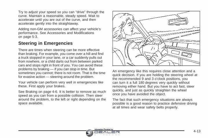
Try to adjust your speed so you can “drive” through thecurve. Maintain a reasonable, steady speed. Wait toaccelerate until you are out of the curve, and thenaccelerate gently into the straightaway.
Adding non-GM accessories can affect your vehicle’sperformance. See Accessories and Modificationson page 5-3.
Steering in EmergenciesThere are times when steering can be more effectivethan braking. For example, you come over a hill and finda truck stopped in your lane, or a car suddenly pulls outfrom nowhere, or a child darts out from between parkedcars and stops right in front of you. You can avoid theseproblems by braking — if you can stop in time. Butsometimes you cannot; there is not room. That is the timefor evasive action — steering around the problem.
Your vehicle can perform very well in emergencies likethese. First apply your brakes.
See Braking on page 4-6. It is better to remove as muchspeed as you can from a possible collision. Then steeraround the problem, to the left or right depending on thespace available.
An emergency like this requires close attention and aquick decision. If you are holding the steering wheel atthe recommended 9 and 3 o’clock positions, youcan turn it a full 180 degrees very quickly withoutremoving either hand. But you have to act fast, steerquickly, and just as quickly straighten the wheelonce you have avoided the object.
The fact that such emergency situations are alwayspossible is a good reason to practice defensive drivingat all times and wear safety belts properly.
4-13Information Provided by:

Off-Road RecoveryYou may find that your right wheels have droppedoff the edge of a road onto the shoulder while youare driving.
If the level of the shoulder is only slightly below thepavement, recovery should be fairly easy. Ease off theaccelerator and then, if there is nothing in the way,steer so that your vehicle straddles the edge ofthe pavement. You can turn the steering wheel up toone-quarter turn until the right front tire contactsthe pavement edge. Then turn your steering wheel to gostraight down the roadway.
PassingThe driver of a vehicle about to pass another on atwo-lane highway waits for just the right moment,accelerates, moves around the vehicle ahead, thengoes back into the right lane again. A simple maneuver?
Not necessarily! Passing another vehicle on a two-lanehighway is a potentially dangerous move, since thepassing vehicle occupies the same lane as oncomingtraffic for several seconds. A miscalculation, an error injudgment, or a brief surrender to frustration or angercan suddenly put the passing driver face to face with theworst of all traffic accidents — the head-on collision.
So here are some tips for passing:
• Drive ahead. Look down the road, to the sidesand to crossroads for situations that might affectyour passing patterns. If you have any doubtwhatsoever about making a successful pass, waitfor a better time.
• Watch for traffic signs, pavement markings andlines. If you can see a sign up ahead that mightindicate a turn or an intersection, delay your pass.A broken center line usually indicates it is allright to pass, providing the road ahead is clear.Never cross a solid line on your side of the lane ora double solid line, even if the road seems emptyof approaching traffic.
4-14Information Provided by:
• Do not get too close to the vehicle you want topass while you are awaiting an opportunity. Forone thing, following too closely reduces your areaof vision, especially if you are following a largervehicle. Also, you will not have adequate space ifthe vehicle ahead suddenly slows or stops.Keep back a reasonable distance.
• When it looks like a chance to pass is coming up,start to accelerate but stay in the right lane and donot get too close. Time your move so you will beincreasing speed as the time comes to move into theother lane. If the way is clear to pass, you will have arunning start that more than makes up for thedistance you would lose by dropping back. And ifsomething happens to cause you to cancel yourpass, you need only slow down and drop back againand wait for another opportunity.
• If other vehicles are lined up to pass a slow vehicle,wait your turn. But take care that someone is nottrying to pass you as you pull out to pass the slowvehicle. Remember to glance over your shoulder andcheck the blind spot.
• Check your mirrors, glance over your shoulder andstart your left lane change signal before moving outof the right lane to pass. When you are far enoughahead of the passed vehicle to see its front in yourinside mirror, activate your right lane change signaland move back into the right lane. Remember that ifyour passenger side outside mirror is convex, thevehicle you just passed may seem to be farther awayfrom you than it really is.
• Try not to pass more than one vehicle at a time ontwo-lane roads. Reconsider before passing thenext vehicle.
• Do not overtake a slowly moving vehicle too rapidly.Even though the brake lamps are not flashing, it maybe slowing down or starting to turn.
• If you are being passed, make it easy for thefollowing driver to get ahead of you. Perhaps you canease a little to the right.
4-15Information Provided by:
Loss of ControlLet us review what driving experts say about whathappens when the three control systems — brakes,steering, and acceleration — do not have enoughfriction where the tires meet the road to do what thedriver has asked.
In any emergency, do not give up. Keep trying tosteer and constantly seek an escape route or area ofless danger.
SkiddingIn a skid, a driver can lose control of the vehicle.Defensive drivers avoid most skids by taking reasonablecare suited to existing conditions, and by not overdrivingthose conditions. But skids are always possible.
The three types of skids correspond to your vehicle’sthree control systems. In the braking skid, your wheelsare not rolling. In the steering or cornering skid, too muchspeed or steering in a curve causes tires to slip and losecornering force. And in the acceleration skid, too muchthrottle causes the driving wheels to spin.
A cornering skid is best handled by easing your foot offthe accelerator pedal.
Remember: Any traction control system helps avoid onlythe acceleration skid. If your traction control system isoff, then an acceleration skid is also best handledby easing your foot off the accelerator pedal.
If your vehicle starts to slide, ease your foot off theaccelerator pedal and quickly steer the way you wantthe vehicle to go. If you start steering quickly enough,your vehicle may straighten out. Always be readyfor a second skid if it occurs.
Of course, traction is reduced when water, snow, ice,gravel, or other material is on the road. For safety, youwill want to slow down and adjust your driving tothese conditions. It is important to slow down on slipperysurfaces because stopping distance will be longer andvehicle control more limited.
While driving on a surface with reduced traction, tryyour best to avoid sudden steering, acceleration,or braking, including engine braking by shifting to alower gear. Any sudden changes could cause the tiresto slide. You may not realize the surface is slipperyuntil your vehicle is skidding. Learn to recognize warningclues — such as enough water, ice, or packed snowon the road to make a mirrored surface — andslow down when you have any doubt.
Remember: Any Anti-Lock Brake System (ABS) helpsavoid only the braking skid.
4-16Information Provided by:

Off-Road DrivingMany of the same design features that help make yourvehicle responsive on paved roads during poor weatherconditions — features like all-wheel drive — help make itmuch better suited for off-road use than a conventionalpassenger car. Its higher ground clearance also helpsyour vehicle step over some off-road obstacles. But yourvehicle does not have features like special underbodyshielding and a transfer case low gear range, things thatare usually thought necessary for extended or severeoff-road service. This guide is for operating your vehicleoff paved roads.
Also, see Braking on page 4-6.
Off-road driving can be great fun. But it does havesome definite hazards. The greatest of these isthe terrain itself.
“Off-roading” means you have left the great NorthAmerican road system behind. Traffic lanes are notmarked. Curves are not banked. There are noroad signs. Surfaces can be slippery, rough, uphill, ordownhill. In short, you have gone right back to nature.
Off-road driving involves some new skills. And that iswhy it is very important that you read this guide. You willfind many driving tips and suggestions. These will helpmake your off-road driving safer and more enjoyable.
Before You Go Off-RoadingThere are some things to do before you go out.For example, be sure to have all necessary maintenanceand service work done. Check to make sure allunderbody shields, if equipped, are properly attached.Is there enough fuel? Is the spare tire fully inflated?Are the fluid levels up where they should be? What arethe local laws that apply to off-roading where youwill be driving? If you do not know, you should checkwith law enforcement people in the area. Will you be onsomeone’s private land? If so, be sure to get thenecessary permission.
4-17Information Provided by:

Loading Your Vehicle for Off-RoadDrivingThere are some important things to remember abouthow to load your vehicle.
• The heaviest things should be on the load floor andforward of the rear axle. Put heavier items as farforward as you can.
• Be sure the load is secured properly, so driving onthe off-road terrain does not toss things around.
{CAUTION:
• Cargo on the load floor piled higher thanthe seatbacks can be thrown forwardduring a sudden stop. You or yourpassengers could be injured. Keep cargobelow the top of the seatbacks.
CAUTION: (Continued)
CAUTION: (Continued)
• Unsecured cargo on the load floor can betossed about when driving over roughterrain. You or your passengers can bestruck by flying objects. Secure thecargo properly.
• Heavy loads on the roof raise the vehicle’scenter of gravity, making it more likely toroll over. You can be seriously or fatallyinjured if the vehicle rolls over. Put heavyloads inside the cargo area, not on theroof. Keep cargo in the cargo area as farforward and low as possible.
You will find other important information in this manual.See Loading Your Vehicle on page 4-44 and Tireson page 5-60.
4-18Information Provided by:
Environmental ConcernsOff-road driving can provide wholesome and satisfyingrecreation. However, it also raises environmentalconcerns. We recognize these concerns and urge everyoff-roader to follow these basic rules for protectingthe environment:
• Always use established trails, roads, and areas thathave been specially set aside for public off-roadrecreational driving; obey all posted regulations.
• Avoid any driving practice that could damagethe environment — shrubs, flowers, trees,grasses — or disturb wildlife (this includeswheel-spinning, breaking down trees, orunnecessary driving through streams or oversoft ground).
• Always carry a litter bag — make sure all refuse isremoved from any campsite before leaving.
• Take extreme care with open fires where permitted,camp stoves, and lanterns.
• Never park your vehicle over dry grass or othercombustible materials that could catch fire fromthe heat of the vehicle’s exhaust system.
Traveling to Remote AreasIt makes sense to plan your trip, especially when goingto a remote area. Know the terrain and plan yourroute. You are much less likely to get bad surprises.Get accurate maps of trails and terrain. Try to learn ofany blocked or closed roads.
It is also a good idea to travel with at least one othervehicle. If something happens to one of them, the othercan help quickly.
Getting Familiar with Off-Road DrivingIt is a good idea to practice in an area that is safeand close to home before you go into the wilderness.Off-road driving does require some new and differentdriving skills. Here is what we mean.
Tune your senses to different kinds of signals. Youreyes, for example, need to constantly sweep the terrainfor unexpected obstacles. Your ears need to listenfor unusual tire or engine sounds. With your arms,hands, feet, and body, you will need to respond tovibrations and vehicle bounce.
4-19Information Provided by:

Controlling your vehicle is the key to successful off-roaddriving. One of the best ways to control your vehicleis to control your speed. Here are some things to keepin mind. At higher speeds:
• You approach things faster and you have less timeto scan the terrain for obstacles.
• You have less time to react.
• You have more vehicle bounce when you driveover obstacles.
• You will need more distance for braking, especiallysince you are on an unpaved surface.
{CAUTION:
When you are driving off-road, bouncing andquick changes in direction can easily throwyou out of position. This could cause you tolose control and crash. So, whether you aredriving on or off the road, you and yourpassengers should wear safety belts.
Scanning the TerrainOff-road driving can take you over many differentkinds of terrain. You need to be familiar with theterrain and its many different features. Here aresome things to consider.
Surface Conditions: Off-roading can take you overhard-packed dirt, gravel, rocks, grass, sand, mud, snow,or ice. Each of these surfaces affects the steering,acceleration, and braking of your vehicle in differentways. Depending upon the kind of surface you are on,you may experience slipping, sliding, wheel spinning,delayed acceleration, poor traction, and longerbraking distances.
Surface Obstacles: Unseen or hidden obstacles canbe hazardous. A rock, log, hole, rut, or bump can startleyou if you are not prepared for them. Often theseobstacles are hidden by grass, bushes, snow, or eventhe rise and fall of the terrain itself. Here are somethings to consider:
• Is the path ahead clear?
• Will the surface texture change abruptly up ahead?
• Does the travel take you uphill or downhill?There is more discussion of these subjects later.
• Will you have to stop suddenly or changedirection quickly?
4-20Information Provided by:
When you drive over obstacles or rough terrain, keep afirm grip on the steering wheel. Ruts, troughs, orother surface features can jerk the wheel out of yourhands if you are not prepared.
When you drive over bumps, rocks, or other obstacles,the wheels can leave the ground. If this happens,even with one or two wheels, you cannot control thevehicle as well or at all.
Because you will be on an unpaved surface, it isespecially important to avoid sudden acceleration,sudden turns, or sudden braking.
In a way, off-road driving requires a different kind ofalertness from driving on paved roads and highways.There are no road signs, posted speed limits, or signallights. You have to use your own good judgmentabout what is safe and what is not.
Drinking and driving can be very dangerous on anyroad. And this is certainly true for off-road driving.At the very time you need special alertness and drivingskills, your reflexes, perceptions, and judgment canbe affected by even a small amount of alcohol.You could have a serious — or even fatal — accident ifyou drink and drive or ride with a driver who hasbeen drinking. See Drunken Driving on page 4-3.
Driving on Off-Road HillsOff-road driving often takes you up, down, or across ahill. Driving safely on hills requires good judgmentand an understanding of what your vehicle can andcannot do. There are some hills that simply cannot bedriven, no matter how well built the vehicle.
{CAUTION:
Many hills are simply too steep for any vehicle.If you drive up them, you will stall. If you drivedown them, you cannot control your speed.If you drive across them, you will roll over.You could be seriously injured or killed. If youhave any doubt about the steepness, do notdrive the hill.
4-21Information Provided by:
Approaching a HillWhen you approach a hill, you need to decide if it isone of those hills that is just too steep to climb, descend,or cross. Steepness can be hard to judge. On a verysmall hill, for example, there may be a smooth, constantincline with only a small change in elevation whereyou can easily see all the way to the top. On a large hill,the incline may get steeper as you near the top, butyou may not see this because the crest of the hillis hidden by bushes, grass, or shrubs.Here are some other things to consider as you approacha hill.• Is there a constant incline, or does the hill get
sharply steeper in places?• Is there good traction on the hillside, or will the
surface cause tire slipping?• Is there a straight path up or down the hill so you
will not have to make turning maneuvers?• Are there obstructions on the hill that can block your
path, such as boulders, trees, logs, or ruts?• What is beyond the hill? Is there a cliff, an
embankment, a drop-off, a fence? Get out andwalk the hill if you do not know. It is the smart wayto find out.
• Is the hill simply too rough? Steep hills often haveruts, gullies, troughs, and exposed rocks becausethey are more susceptible to the effects of erosion.
Driving UphillOnce you decide you can safely drive up the hill,you need to take some special steps.• Use a low gear and get a firm grip on the
steering wheel.• Get a smooth start up the hill and try to maintain
your speed. Do not use more power than youneed, because you do not want the wheels to startspinning or sliding.
• Try to drive straight up the hill if at all possible.If the path twists and turns, you might want tofind another route.
{CAUTION:
Turning or driving across steep hills can bedangerous. You could lose traction, slidesideways, and possibly roll over. You could beseriously injured or killed. When driving uphills, always try to go straight up.
4-22Information Provided by:

• Ease up on your speed as you approach the top ofthe hill.
• Attach a flag to the vehicle to make you morevisible to approaching traffic on trails or hills.
• Sound the horn as you approach the top of the hillto let opposing traffic know you are there.
• Use the headlamps even during the day.They make you more visible to oncoming traffic.
{CAUTION:
Driving to the top (crest) of a hill at full speedcan cause an accident. There could be adrop-off, embankment, cliff, or even anothervehicle. You could be seriously injured orkilled. As you near the top of a hill, slow downand stay alert.
Q: What should I do if my vehicle stalls, or is aboutto stall, and I cannot make it up the hill?
A: If this happens, there are some things you shoulddo, and there are some things you must not do.First, here is what you should do:
• Push the brake pedal to stop the vehicle andkeep it from rolling backwards. Also, apply theparking brake.
• If the engine is still running, shift the transmission toREVERSE (R), release the parking brake, andslowly back down the hill in REVERSE (R).
• If the engine has stopped running, you will need torestart it. With the brake pedal pressed and theparking brake still applied, shift the transmission toPARK (P) and restart the engine. Then, shift toREVERSE (R), release the parking brake, andslowly back down the hill as straight as possible inREVERSE (R).
• As you are backing down the hill, put your left handon the steering wheel at the 12 o’clock position.This way, you will be able to tell if the wheels arestraight and maneuver as you back down. It isbest that you back down the hill with the wheelsstraight rather than in the left or right direction.Turning the wheel too far to the left or rightwill increase the possibility of a rollover.
4-23Information Provided by:

Here are some things you must not do if you stall, orare about to stall, when going up a hill.
• Never attempt to prevent a stall by shifting intoNEUTRAL (N) to rev-up the engine and regainforward momentum. This will not work. Your vehiclewill roll backwards very quickly and you could goout of control.Instead, apply the regular brake to stop the vehicle.Then apply the parking brake. Shift toREVERSE (R), release the parking brake, andslowly back straight down.
• Never attempt to turn around if you are about tostall when going up a hill. If the hill is steepenough to stall your vehicle, it is steep enough tocause you to roll over if you turn around. If youcannot make it up the hill, you must back straightdown the hill.
Q: Suppose, after stalling, I try to back down thehill and decide I just cannot do it. What shouldI do?
A: Set the parking brake, put the transmission inPARK (P) and turn off the engine. Leave thevehicle and go get some help. Exit on the uphillside and stay clear of the path the vehicle wouldtake if it rolled downhill.
Driving DownhillWhen off-roading takes you downhill, you will want toconsider a number of things:
• How steep is the downhill? Will I be able to maintainvehicle control?
• What is the surface like? Smooth? Rough?Slippery? Hard-packed dirt? Gravel?
• Are there hidden surface obstacles? Ruts?Logs? Boulders?
• What is at the bottom of the hill? Is there a hiddencreek bank or even a river bottom with large rocks?
If you decide you can go down a hill safely, then try tokeep your vehicle headed straight down, and use alow gear. This way, engine drag can help the brakes andthey will not have to do all the work. Descend slowly,keeping your vehicle under control at all times.
4-24Information Provided by:

{CAUTION:
Heavy braking when going down a hill cancause your brakes to overheat and fade. Thiscould cause loss of control and a seriousaccident. Apply the brakes lightly whendescending a hill and use a low gear to keepvehicle speed under control.
Q: Are there some things I should not do whendriving down a hill?
A: Yes! These are important because if you ignorethem you could lose control and have a seriousaccident.
• When driving downhill, avoid turns that take youacross the incline of the hill. A hill that is not toosteep to drive down may be too steep to driveacross. You could roll over if you do not drivestraight down.
• Never go downhill with the transmission inNEUTRAL (N). This is called “free-wheeling.”The brakes will have to do all the work andcould overheat and fade.
Q: Am I likely to stall when going downhill?
A: It is much more likely to happen going uphill. But ifit happens going downhill, here is what to do.
1. Stop your vehicle by applying the regular brakes.Apply the parking brake.
2. Shift to PARK (P) and, while still braking, restart theengine.
3. Shift back to a low gear, release the parking brake,and drive straight down.
4. If the engine will not start, get out and get help.
4-25Information Provided by:
Driving Across an InclineSooner or later, an off-road trail will probably go acrossthe incline of a hill. If this happens, you have todecide whether to try to drive across the incline. Hereare some things to consider:
• A hill that can be driven straight up or down may betoo steep to drive across. When you go straight up ordown a hill, the length of the wheel base — thedistance from the front wheels to the rearwheels — reduces the likelihood the vehicle willtumble end over end. But when you drive across anincline, the much more narrow track width — thedistance between the left and right wheels — maynot prevent the vehicle from tilting and rolling over.Also, driving across an incline puts more weight onthe downhill wheels. This could cause a downhillslide or a rollover.
• Surface conditions can be a problem when you driveacross a hill. Loose gravel, muddy spots, or even wetgrass can cause your tires to slip sideways, downhill.If the vehicle slips sideways, it can hit something thatwill trip it — a rock, a rut, etc. — and roll over.
• Hidden obstacles can make the steepness of theincline even worse. If you drive across a rock with theuphill wheels, or if the downhill wheels drop into a rutor depression, your vehicle can tilt even more.
For reasons like these, you need to decide carefullywhether to try to drive across an incline. Just because thetrail goes across the incline does not mean you have todrive it. The last vehicle to try it might have rolled over.
{CAUTION:
Driving across an incline that is too steep willmake your vehicle roll over. You could beseriously injured or killed. If you have anydoubt about the steepness of the incline, donot drive across it. Find another route instead.
Q: What if I am driving across an incline that is nottoo steep, but I hit some loose gravel and startto slide downhill. What should I do?
A: If you feel your vehicle starting to slide sideways,turn downhill. This should help straighten out thevehicle and prevent the side slipping. However,a much better way to prevent this is to get out and“walk the course” so you know what the surfaceis like before you drive it.
4-26Information Provided by:

Stalling on an InclineIf your vehicle stalls when you are crossing an incline,be sure you, and any passengers, get out on theuphill side, even if the door there is harder to open. Ifyou get out on the downhill side and the vehicle starts toroll over, you will be right in its path.
If you have to walk down the slope, stay out of the paththe vehicle will take if it does roll over.
{CAUTION:
Getting out on the downhill (low) side of avehicle stopped across an incline isdangerous. If the vehicle rolls over, you couldbe crushed or killed. Always get out on theuphill (high) side of the vehicle and stay wellclear of the rollover path.
Driving in Mud, Sand, Snow, or IceWhen you drive in mud, snow, or sand, the wheels willnot get good traction. You cannot accelerate asquickly, turning is more difficult, and you will need longerbraking distances.
It is best to use a low gear when you are in mud — thedeeper the mud, the lower the gear. In really deepmud, the idea is to keep your vehicle moving so you donot get stuck.
4-27Information Provided by:
When you drive on sand, you will sense a change inwheel traction. But it will depend upon how looselypacked the sand is. On loosely packed sand, such ason beaches or sand dunes, the tires will tend to sink intothe sand. This has an effect on steering, accelerating,and braking. Drive at a reduced speed and avoid sharpturns or abrupt maneuvers.
Hard packed snow and ice offer the worst tire traction.On these surfaces, it is very easy to lose control.On wet ice, for example, the traction is so poor that youwill have difficulty accelerating. And if you do getmoving, poor steering and difficult braking can causeyou to slide out of control.
{CAUTION:
Driving on frozen lakes, ponds, or rivers canbe dangerous. Underwater springs, currentsunder the ice, or sudden thaws can weaken theice. Your vehicle could fall through the ice andyou and your passengers could drown. Driveyour vehicle on safe surfaces only.
Driving in WaterHeavy rain can mean flash flooding, and flood watersdemand extreme caution.
Find out how deep the water is before you drive throughit. If it is deep enough to cover the wheel hubs, axles,or exhaust pipe, do not try it — you probably will not getthrough. Also, water that deep can damage the axleand other vehicle parts.
If the water is not too deep, drive slowly through it.At faster speeds, water splashes on the ignition systemand your vehicle can stall. Stalling can also occur ifyou get the tailpipe under water. And, as long asthe tailpipe is under water, you will never be able tostart the engine. When you go through water, rememberthat when the brakes get wet, it may take you longerto stop.
4-28Information Provided by:

{CAUTION:
Driving through rushing water can bedangerous. Deep water can sweep yourvehicle downstream and you and yourpassengers could drown. If it is only shallowwater, it can still wash away the ground fromunder your tires, and you could lose tractionand roll the vehicle over. Do not drive throughrushing water.
See Driving in Rain and on Wet Roads on page 4-31 formore information on driving through water.
After Off-Road DrivingRemove any brush or debris that has collected on theunderbody, chassis, or under the hood. Theseaccumulations can be a fire hazard.
After operation in mud or sand, have the brake liningscleaned and checked. These substances can causeglazing and uneven braking. Check the body structure,steering, suspension, wheels, tires, and exhaustsystem for damage. Also, check the fuel lines andcooling system for any leakage.
Your vehicle will require more frequent service due tooff-road use. Refer to the Maintenance Schedulefor additional information.
4-29Information Provided by:

Driving at NightNight driving is more dangerous than day driving.One reason is that some drivers are likely to beimpaired — by alcohol or drugs, with night visionproblems, or by fatigue.
Here are some tips on night driving.
• Drive defensively.
• Do not drink and drive.
• Adjust the inside rearview mirror to reduce the glarefrom headlamps behind you.
• Since you cannot see as well, you may need toslow down and keep more space between youand other vehicles.
• Slow down, especially on higher speed roads.Your vehicle’s headlamps can light up only somuch road ahead.
• In remote areas, watch for animals.
• If you are tired, pull off the road in a safe placeand rest.
No one can see as well at night as in the daytime.But as we get older these differences increase.A 50-year-old driver may require at least twice as muchlight to see the same thing at night as a 20-year-old.
What you do in the daytime can also affect your nightvision. For example, if you spend the day in brightsunshine you are wise to wear sunglasses. Your eyeswill have less trouble adjusting to night. But if youare driving, do not wear sunglasses at night. They maycut down on glare from headlamps, but they alsomake a lot of things invisible.
You can be temporarily blinded by approachingheadlamps. It can take a second or two, or even severalseconds, for your eyes to re-adjust to the dark. Whenyou are faced with severe glare, as from a driverwho does not lower the high beams, or a vehicle withmisaimed headlamps, slow down a little. Avoidstaring directly into the approaching headlamps.
Keep the windshield and all the glass on your vehicleclean — inside and out. Glare at night is made muchworse by dirt on the glass. Even the inside of the glasscan build up a film caused by dust. Dirty glass makeslights dazzle and flash more than clean glass would,making the pupils of your eyes contract repeatedly.
Remember that the headlamps light up far less of aroadway when you are in a turn or curve. Keep youreyes moving; that way, it is easier to pick out dimlylighted objects. Just as the headlamps should bechecked regularly for proper aim, so should your eyesbe examined regularly. Some drivers suffer fromnight blindness — the inability to see in dim light — andare not even aware of it.
4-30Information Provided by:

Driving in Rain and on Wet Roads
Rain and wet roads can mean driving trouble. On a wetroad, you cannot stop, accelerate, or turn as wellbecause your tire-to-road traction is not as good as ondry roads. And, if your tires do not have much treadleft, you will get even less traction. It is always wise togo slower and be cautious if rain starts to fall whileyou are driving. The surface may get wet suddenly whenyour reflexes are tuned for driving on dry pavement.
The heavier the rain, the harder it is to see. Even if yourwindshield wiper blades are in good shape, a heavyrain can make it harder to see road signs andtraffic signals, pavement markings, the edge of the road,and even people walking.It is wise to keep your wiping equipment in good shapeand keep your windshield washer fluid reservoir filledwith washer fluid. Replace your windshield wiper insertswhen they show signs of streaking or missing areason the windshield, or when strips of rubber startto separate from the inserts.
{CAUTION:
Wet brakes can cause accidents. They will notwork as well in a quick stop and may causepulling to one side. You could lose control ofthe vehicle.After driving through a large puddle of wateror a car wash, apply your brake pedal lightlyuntil your brakes work normally.
Driving too fast through large water puddles or evengoing through some car washes can cause problems,too. The water may affect your brakes. Try to avoidpuddles. But if you cannot, try to slow down beforeyou hit them.
4-31Information Provided by:

HydroplaningHydroplaning is dangerous. So much water can build upunder your tires that they can actually ride on thewater. This can happen if the road is wet enough andyou are going fast enough. When your vehicle ishydroplaning, it has little or no contact with the road.
Hydroplaning does not happen often. But it can if yourtires do not have much tread or if the pressure inone or more is low. It can happen if a lot of water isstanding on the road. If you can see reflectionsfrom trees, telephone poles, or other vehicles, andraindrops dimple the water’s surface, there couldbe hydroplaning.
Hydroplaning usually happens at higher speeds. Therejust is not a hard and fast rule about hydroplaning.The best advice is to slow down when it is raining.
Driving Through Deep Standing Water
Notice: If you drive too quickly through deeppuddles or standing water, water can come inthrough your engine’s air intake and badly damageyour engine. Never drive through water that isslightly lower than the underbody of your vehicle. Ifyou cannot avoid deep puddles or standing water,drive through them very slowly.
Driving Through Flowing Water
{CAUTION:
Flowing or rushing water creates strong forces.If you try to drive through flowing water, as youmight at a low water crossing, your vehicle canbe carried away. As little as six inches offlowing water can carry away a smaller vehicle.If this happens, you and other vehicleoccupants could drown. Do not ignore policewarning signs, and otherwise be very cautiousabout trying to drive through flowing water.
Some Other Rainy Weather Tips• Turn on your low-beam headlamps — not just
your parking lamps — to help make you morevisible to others.
• Besides slowing down, allow some extra followingdistance. And be especially careful when youpass another vehicle. Allow yourself more clearroom ahead, and be prepared to have yourview restricted by road spray.
• Have good tires with proper tread depth. See Tireson page 5-60.
4-32Information Provided by:

City Driving
One of the biggest problems with city streets is theamount of traffic on them. You will want to watch out forwhat the other drivers are doing and pay attention totraffic signals.
Here are ways to increase your safety in city driving:
• Know the best way to get to where you aregoing. Get a city map and plan your trip intoan unknown part of the city just as you would for across-country trip.
• Try to use the freeways that rim and crisscrossmost large cities. You will save time and energy.See Freeway Driving on page 4-34.
• Treat a green light as a warning signal. A trafficlight is there because the corner is busy enoughto need it. When a light turns green, and just beforeyou start to move, check both ways for vehiclesthat have not cleared the intersection or maybe running the red light.
4-33Information Provided by:

Freeway Driving
Mile for mile, freeways — also called thruways, parkways,expressways, turnpikes, or superhighways — are thesafest of all roads. But they have their own special rules.
The most important advice on freeway driving is: Keepup with traffic and keep to the right. Drive at thesame speed most of the other drivers are driving.Too-fast or too-slow driving breaks a smooth traffic flow.Treat the left lane on a freeway as a passing lane.
At the entrance, there is usually a ramp that leads to thefreeway. If you have a clear view of the freeway as youdrive along the entrance ramp, you should begin to checktraffic. Try to determine where you expect to blend withthe flow. Try to merge into the gap at close to theprevailing speed. Switch on your turn signal, check yourmirrors, and glance over your shoulder as often asnecessary. Try to blend smoothly with the traffic flow.Once you are on the freeway, adjust your speed to theposted limit or to the prevailing rate if it is slower.Stay in the right lane unless you want to pass.Before changing lanes, check your mirrors. Then useyour turn signal.Just before you leave the lane, glance quickly over yourshoulder to make sure there is not another vehicle inyour blind spot.Once you are moving on the freeway, make certain youallow a reasonable following distance. Expect tomove slightly slower at night.When you want to leave the freeway, move to theproper lane well in advance. If you miss your exit, donot, under any circumstances, stop and back up. Driveon to the next exit.The exit ramp can be curved, sometimes quite sharply.The exit speed is usually posted.Reduce your speed according to your speedometer, notto your sense of motion. After driving for any distanceat higher speeds, you may tend to think you aregoing slower than you actually are.
4-34Information Provided by:

Before Leaving on a Long TripMake sure you are ready. Try to be well rested. If youmust start when you are not fresh — such as aftera day’s work — do not plan to make too many miles thatfirst part of the journey. Wear comfortable clothingand shoes you can easily drive in.Is your vehicle ready for a long trip? If you keep itserviced and maintained, it is ready to go. If it needsservice, have it done before starting out. Of course,you will find experienced and able service experts inGM dealerships all across North America. They will beready and willing to help if you need it.Here are some things you can check before a trip:• Windshield Washer Fluid: Is the reservoir full?
Are all windows clean inside and outside?• Wiper Blades: Are they in good shape?• Fuel, Engine Oil, Other Fluids: Have you checked
all levels?• Lamps: Are they all working? Are the lenses clean?• Tires: They are vitally important to a safe,
trouble-free trip. Is the tread good enough forlong-distance driving? Are the tires all inflated to therecommended pressure?
• Weather Forecasts: What is the weather outlookalong your route? Should you delay your trip ashort time to avoid a major storm system?
• Maps: Do you have up-to-date maps?
Highway HypnosisIs there actually such a condition as highway hypnosis?Or is it just plain falling asleep at the wheel? Call ithighway hypnosis, lack of awareness, or whatever.
There is something about an easy stretch of road withthe same scenery, along with the hum of the tires on theroad, the drone of the engine, and the rush of thewind against the vehicle that can make you sleepy.Do not let it happen to you! If it does, your vehicle canleave the road in less than a second, and you couldcrash and be injured.
What can you do about highway hypnosis? First, beaware that it can happen.
Then here are some tips:
• Make sure your vehicle is well ventilated, with acomfortably cool interior.
• Keep your eyes moving. Scan the road ahead andto the sides. Check your mirrors and yourinstruments frequently.
• If you get sleepy, pull off the road into a rest,service, or parking area and take a nap, get someexercise, or both. For safety, treat drowsinesson the highway as an emergency.
4-35Information Provided by:

Hill and Mountain Roads
Driving on steep hills or mountains is different fromdriving in flat or rolling terrain.
If you drive regularly in steep country, or if you areplanning to visit there, here are some tips that can makeyour trips safer and more enjoyable. See Off-RoadDriving on page 4-17 for information about drivingoff-road.
• Keep your vehicle in good shape. Check all fluidlevels and also the brakes, tires, cooling system,and transmission. These parts can work hardon mountain roads.
{CAUTION:
If you do not shift down, your brakes could getso hot that they would not work well. Youwould then have poor braking or even nonegoing down a hill. You could crash. Shift downto let your engine assist your brakes on asteep downhill slope.
4-36Information Provided by:

{CAUTION:
Coasting downhill in NEUTRAL (N) or with theignition off is dangerous. Your brakes will haveto do all the work of slowing down. They couldget so hot that they would not work well. Youwould then have poor braking or even nonegoing down a hill. You could crash. Alwayshave your engine running and your vehicle ingear when you go downhill.
• Know how to go down hills. The most importantthing to know is this: let your engine do some ofthe slowing down. Shift to a lower gear when you godown a steep or long hill.
• Know how to go uphill. You may want to shift downto a lower gear. The lower gears help cool yourengine and transmission, and you can climb thehill better.
• Stay in your own lane when driving on two-laneroads in hills or mountains. Do not swing wideor cut across the center of the road. Drive at speedsthat let you stay in your own lane.
• As you go over the top of a hill, be alert. Therecould be something in your lane, like a stalled car oran accident.
• You may see highway signs on mountains thatwarn of special problems. Examples are longgrades, passing or no-passing zones, a falling rocksarea, or winding roads. Be alert to these and takeappropriate action.
4-37Information Provided by:

Winter Driving
Here are some tips for winter driving:
• Have your vehicle in good shape for winter.
• You may want to put winter emergency supplies inyour vehicle.
Also see Tires on page 5-60.
Include an ice scraper, a small brush or broom, asupply of windshield washer fluid, a rag, some winterouter clothing, a small shovel, a flashlight, a redcloth, and a couple of reflective warning triangles. And,if you will be driving under severe conditions, includea small bag of sand, a piece of old carpet, or a couple ofburlap bags to help provide traction. Be sure youproperly secure these items in your vehicle.
Driving on Snow or IceMost of the time, those places where the tires meet theroad probably have good traction.
However, if there is snow or ice between the tires andthe road, you can have a very slippery situation. You willhave a lot less traction, or grip, and will need to bevery careful.
4-38Information Provided by:

What is the worst time for this? Wet ice. Very cold snowor ice can be slick and hard to drive on. But wet icecan be even more trouble because it may offer the leasttraction of all. You can get wet ice when it is aboutfreezing, 32°F (0°C), and freezing rain begins to fall.Try to avoid driving on wet ice until salt and sand crewscan get there.
Whatever the condition — smooth ice, packed, blowing,or loose snow — drive with caution.
Accelerate gently. Try not to break the fragile traction.If you accelerate too fast, the drive wheels will spin andpolish the surface under the tires even more.
Your Anti-Lock Brake System (ABS) improves yourvehicle’s stability when you make a hard stop ona slippery road. Even though you have ABS, you willwant to begin stopping sooner than you would ondry pavement. See Anti-Lock Brake System (ABS) onpage 4-7.
• Allow greater following distance on anyslippery road.
• Watch for slippery spots. The road might be fineuntil you hit a spot that is covered with ice.On an otherwise clear road, ice patches may appearin shaded areas where the sun cannot reach,such as around clumps of trees, behind buildings,or under bridges. Sometimes the surface of acurve or an overpass may remain icy when thesurrounding roads are clear. If you see a patch ofice ahead of you, brake before you are on it. Try notto brake while you are actually on the ice, andavoid sudden steering maneuvers.
4-39Information Provided by:
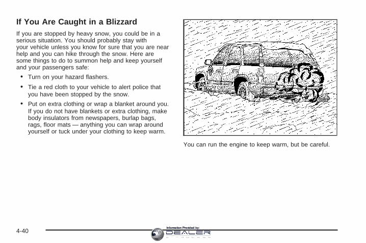
If You Are Caught in a BlizzardIf you are stopped by heavy snow, you could be in aserious situation. You should probably stay withyour vehicle unless you know for sure that you are nearhelp and you can hike through the snow. Here aresome things to do to summon help and keep yourselfand your passengers safe:
• Turn on your hazard flashers.
• Tie a red cloth to your vehicle to alert police thatyou have been stopped by the snow.
• Put on extra clothing or wrap a blanket around you.If you do not have blankets or extra clothing, makebody insulators from newspapers, burlap bags,rags, floor mats — anything you can wrap aroundyourself or tuck under your clothing to keep warm.
You can run the engine to keep warm, but be careful.
4-40Information Provided by:

{CAUTION:
Snow can trap exhaust gases under yourvehicle. This can cause deadly CO (carbonmonoxide) gas to get inside. CO couldovercome you and kill you. You cannot see itor smell it, so you might not know it is in yourvehicle. Clear away snow from around thebase of your vehicle, especially any that isblocking your exhaust pipe. And check aroundagain from time to time to be sure snow doesnot collect there.
Open a window just a little on the side of thevehicle that is away from the wind. This willhelp keep CO out.
Run your engine only as long as you must. This savesfuel. When you run the engine, make it go a littlefaster than just idle. That is, push the acceleratorslightly. This uses less fuel for the heat that you getand it keeps the battery charged. You will need awell-charged battery to restart the vehicle, and possiblyfor signaling later on with your headlamps. Let theheater run for a while.
Then, shut the engine off and close the window almostall the way to preserve the heat. Start the engineagain and repeat this only when you feel reallyuncomfortable from the cold. But do it as little aspossible. Preserve the fuel as long as you can. Tohelp keep warm, you can get out of the vehicle and dosome fairly vigorous exercises every half hour or sountil help comes.
4-41Information Provided by:

If Your Vehicle is Stuck in Sand,Mud, Ice or SnowIn order to free your vehicle when it is stuck, you willneed to spin the wheels, but you do not want tospin your wheels too fast. The method known as rockingcan help you get out when you are stuck, but youmust use caution.
{CAUTION:
If you let your tires spin at high speed, they canexplode, and you or others could be injured.And, the transmission or other parts of thevehicle can overheat. That could cause anengine compartment fire or other damage.When you are stuck, spin the wheels as little aspossible. Do not spin the wheels above 35 mph(55 km/h) as shown on the speedometer.
Notice: Spinning your wheels can destroy parts ofyour vehicle as well as the tires. If you spin thewheels too fast while shifting your transmissionback and forth, you can destroy your transmission.
For more information about using tire chains on yourvehicle, see Tire Chains on page 5-79.
Rocking Your Vehicle to Get It OutFirst, turn your steering wheel left and right. That willclear the area around your front wheels. If your vehiclehas the StabiliTrak® System, turn the system off bypressing the StabiliTrak® button so that the STABILITYSYS DISABLED message and the traction off lightare illuminated on the instrument panel cluster. Thenshift back and forth between REVERSE (R) and aforward gear, spinning the wheels as little as possible.Release the accelerator pedal while you shift, and presslightly on the accelerator pedal when the transmissionis in gear. By slowly spinning your wheels in the forwardand reverse directions, you will cause a rockingmotion that may free your vehicle. If that does not getyou out after a few tries, you may need to be towed out.Or, you can use your recovery hooks. If you do needto be towed out, see Towing Your Vehicle on page 4-50.
4-42Information Provided by:

Recovery Hooks
{CAUTION:
These hooks, when used, are under a lot offorce. Always pull the vehicle straight out.Never pull on the hooks at a sideways angle.The hooks could break off and you or otherscould be injured from the chain or cablesnapping back.
Notice: Never use recovery hooks to tow thevehicle. Your vehicle could be damaged and it wouldnot be covered by warranty.
Your vehicle has recovery hooks at the front of thevehicle. You may need to use them if you are stuckoff-road and need to be pulled to some place where youcan continue driving.
4-43Information Provided by:

Loading Your VehicleIt is very important to know how much weight yourvehicle can carry. This weight is called the vehiclecapacity weight and includes the weight of all occupants,cargo, and all nonfactory-installed options. Two labelson your vehicle show how much weight it was designedto carry, the Tire and Loading Information label andthe Certification/Tire label.
{CAUTION:
Do not load your vehicle any heavier than theGross Vehicle Weight Rating (GVWR), or eitherthe maximum front or rear Gross Axle WeightRating (GAWR). If you do, parts on yourvehicle can break, and it can change the wayyour vehicle handles. These could cause youto lose control and crash. Also, overloadingcan shorten the life of your vehicle.
Tire and Loading Information Label
A vehicle specific Tire and Loading Information label isattached to the center pillar (B-pillar). With the driver’sdoor open, you will find the label attached belowthe door lock post (striker). The tire and loadinginformation label shows the number of occupant seatingpositions (A), and the maximum vehicle capacityweight (B) in kilograms and pounds.The Tire and Loading Information label also shows thesize of the original equipment tires (C) and therecommended cold tire inflation pressures (D). For moreinformation on tires and inflation see Tires on page 5-60and Inflation - Tire Pressure on page 5-66.
Label Example
4-44Information Provided by:
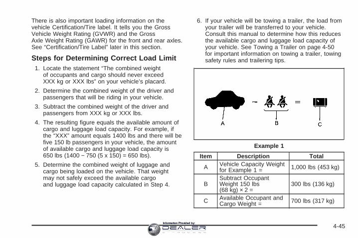
There is also important loading information on thevehicle Certification/Tire label. It tells you the GrossVehicle Weight Rating (GVWR) and the GrossAxle Weight Rating (GAWR) for the front and rear axles.See “Certification/Tire Label” later in this section.
Steps for Determining Correct Load Limit1. Locate the statement “The combined weight
of occupants and cargo should never exceedXXX kg or XXX lbs” on your vehicle’s placard.
2. Determine the combined weight of the driver andpassengers that will be riding in your vehicle.
3. Subtract the combined weight of the driver andpassengers from XXX kg or XXX lbs.
4. The resulting figure equals the available amount ofcargo and luggage load capacity. For example, ifthe “XXX” amount equals 1400 lbs and there will befive 150 lb passengers in your vehicle, the amountof available cargo and luggage load capacity is650 lbs (1400 − 750 (5 x 150) = 650 lbs).
5. Determine the combined weight of luggage andcargo being loaded on the vehicle. That weightmay not safely exceed the available cargoand luggage load capacity calculated in Step 4.
6. If your vehicle will be towing a trailer, the load fromyour trailer will be transferred to your vehicle.Consult this manual to determine how this reducesthe available cargo and luggage load capacity ofyour vehicle. See Towing a Trailer on page 4-50for important information on towing a trailer, towingsafety rules and trailering tips.
Item Description Total
A Vehicle Capacity Weightfor Example 1 = 1,000 lbs (453 kg)
BSubtract OccupantWeight 150 lbs(68 kg) × 2 =
300 lbs (136 kg)
C Available Occupant andCargo Weight = 700 lbs (317 kg)
Example 1
4-45Information Provided by:

Item Description Total
A Vehicle Capacity Weightfor Example 2 = 1,000 lbs (453 kg)
BSubtract OccupantWeight 150 lbs(68 kg) × 5 =
750 lbs (136 kg)
C Available CargoWeight = 250 lbs (113 kg)
Item Description Total
A Vehicle Capacity Weightfor Example 3 = 1,000 lbs (453 kg)
BSubtract OccupantWeight 200 lbs(91 kg) × 5 =
1,000 lbs (453 kg)
C Available CargoWeight = 0 lbs (0 kg)
Refer to your vehicle’s tire and loading information labelfor specific information about your vehicle’s capacityweight and seating positions. The combined weight ofthe driver, passengers and cargo should neverexceed your vehicle’s capacity weight.
Example 2 Example 3
4-46Information Provided by:

Certification/Tire Label
A vehicle specific Certification/Tire label is attached tothe rear edge of the driver’s door. The label showsthe size of your vehicle’s original tires and the inflationpressures needed to obtain the gross weight capacityof your vehicle. This is called Gross Vehicle WeightRating (GVWR). The GVWR includes the weight of thevehicle, all occupants, fuel, and cargo.
The Certification/Tire label also tells you the maximumweights for the front and rear axles, called Gross AxleWeight Rating (GAWR). To find out the actual loads onyour front and rear axles, you need to go to a weighstation and weigh your vehicle. Your dealer can help youwith this. Be sure to spread out your load equally onboth sides of the center line.
Never exceed the GVWR for your vehicle, or the GAWRfor either the front or rear axle.
And, if you do have a heavy load, you should spreadit out.
{CAUTION:
In the case of a sudden stop or collision,things carried in the bed of your truck couldshift forward and come into the passengerarea, injuring you and others. If you put thingsin the bed of your truck, you should make surethey are properly secured.
4-47Information Provided by:

{CAUTION:
Do not load your vehicle any heavier than theGross Vehicle Weight Rating (GVWR), or eitherthe maximum front or rear Gross Axle WeightRating (GAWR). If you do, parts on yourvehicle can break, and it can change the wayyour vehicle handles. These could cause youto lose control and crash. Also, overloadingcan shorten the life of your vehicle.
Your warranty does not cover parts or components thatfail because of overloading.
The label will help you decide how much cargo andinstalled equipment your truck can carry.
Using heavier suspension components to get addeddurability might not change your weight ratings. Ask yourdealer to help you load your vehicle the right way.
If you put things inside your vehicle — like suitcases,tools, packages, or anything else — they go as fastas the vehicle goes. If you have to stop or turn quickly,or if there is a crash, they will keep going.
{CAUTION:
Things you put inside your vehicle can strikeand injure people in a sudden stop or turn, orin a crash.
• Put things in the cargo area of yourvehicle. Try to spread the weight evenly.
• Never stack heavier things, like suitcases,inside the vehicle so that some of themare above the tops of the seats.
• Do not leave an unsecured child restraintin your vehicle.
• When you carry something inside thevehicle, secure it whenever you can.
• Do not leave a seat folded down unlessyou need to.
There is also important loading information for off-roaddriving in this manual. See “Loading Your Vehiclefor Off-Road Driving” under Off-Road Driving onpage 4-17.
4-48Information Provided by:
Add-On EquipmentWhen you carry removable items, you may need to puta limit on how many people you can carry insideyour vehicle. Be sure to weigh your vehicle before youbuy and install the new equipment.
Notice: Overloading your vehicle may causedamage. Repairs would not be covered by yourwarranty. Do not overload your vehicle.
Remember not to exceed the Gross Axle Weight Rating(GAWR) of the front or rear axle.
The Cargo Weight Rating (CWR) is the maximumweight of the load your vehicle can carry. It does notinclude the weight of the people inside. But youcan figure about 150 lbs (68 kg) for each seat.
The total cargo load must not be more than yourvehicle’s CWR.
Automatic Level ControlThe automatic level control rear suspension comes as apart of the Road Sensing Suspension. See RoadSensing Suspension on page 4-9.
This type of level control is fully automatic and willprovide a better leveled riding position as well as betterhandling under a variety of passenger and loadingconditions. An air compressor connected to the rearshocks will raise or lower the rear of the vehicle tomaintain proper vehicle height. The system is activatedwhen the ignition key is turned to RUN and willautomatically adjust vehicle height thereafter. The systemmay exhaust (lower vehicle height) for up to 10 minutesafter the ignition key has been turned to LOCK. You mayhear the air compressor operating when the height isbeing adjusted.
If a weight-distributing hitch is being used, it isrecommended to allow the shocks to inflate, therebyleveling the vehicle prior to adjusting the height.See “Weight Distributing Hitches and Weight CarryingHitches” under Towing a Trailer on page 4-50.
Truck-Camper Loading InformationYour vehicle was neither designed nor intended to carrya slide-in type camper.
Notice: Adding a slide-in camper or similarequipment to your vehicle can damage it, and therepairs would not be covered by your warranty.Do not install a slide-in camper or similar equipmenton your vehicle.
4-49Information Provided by:

Towing
Towing Your VehicleConsult your dealer or a professional towing service ifyou need to have your disabled vehicle towed.See Roadside Service on page 7-6.If you want to tow your vehicle behind another vehiclefor recreational purposes (such as behind a motorhome),see Recreational Vehicle Towing following.
Recreational Vehicle TowingRecreational vehicle towing means towing your vehiclebehind another vehicle — such as behind a motorhome.The two most common types of recreational vehicletowing are known as “dinghy towing” (towing your vehiclewith all four wheels on the ground) and “dolly towing”(towing your vehicle with two wheels on the ground andtwo wheels up on a device known as a “dolly”).
Dinghy Towing and Dolly TowingAll-Wheel Drive VehiclesNotice: Towing an all-wheel-drive vehicle with allfour wheels on the ground, or even with only two ofits wheels on the ground, will damage drivetraincomponents. Do not tow an all-wheel-drive vehicle ifany of its wheels will be on the ground.
Your vehicle is not designed to be towed with any of thewheels on the ground. If your vehicle must be towed,see Towing Your Vehicle on page 4-50.
Towing a TrailerDo not tow a trailer during break-in. See New VehicleBreak-In on page 2-25 for more information.
4-50Information Provided by:

{CAUTION:
If you do not use the correct equipment anddrive properly, you can lose control when youpull a trailer. For example, if the trailer is tooheavy, the brakes may not work well — or evenat all. You and your passengers could beseriously injured. Pull a trailer only if you havefollowed all the steps in this section. Ask yourdealer for advice and information about towinga trailer with your vehicle.
Notice: Pulling a trailer improperly can damageyour vehicle and result in costly repairs not coveredby your warranty. To pull a trailer correctly, followthe advice in this part, and see your dealer forimportant information about towing a trailer withyour vehicle.
To identify the trailering capacity of your vehicle, youshould read the information in “Weight of the Trailer” thatappears later in this section.
Trailering is different than just driving your vehicle byitself. Trailering means changes in handling,acceleration, braking, durability and fuel economy.Successful, safe trailering takes correct equipment, andit has to be used properly.
That’s the reason for this part. In it are many time-tested,important trailering tips and safety rules. Many ofthese are important for your safety and that of yourpassengers. So please read this section carefully beforeyou pull a trailer.
4-51Information Provided by:

If You Do Decide To Pull A TrailerIf you do, here are some important points:• There are many different laws, including speed limit
restrictions, having to do with trailering. Make sureyour rig will be legal, not only where you livebut also where you’ll be driving. A good source forthis information can be state or provincial police.
• Consider using a sway control. See “Hitches” laterin this section.
• Don’t tow a trailer at all during the first 500 miles(800 km) your new vehicle is driven. Your engine,axle or other parts could be damaged.
• Then, during the first 500 miles (800 km) that youtow a trailer, don’t drive over 50 mph (80 km/h)and don’t make starts at full throttle. This helps yourengine and other parts of your vehicle wear in atthe heavier loads.
• You can tow in DRIVE (D). You may want to shiftthe transmission to THIRD (3) or, if necessary, alower gear selection if the transmission shiftstoo often (e.g., under heavy loads and/or hillyconditions). See “Tow/Haul Mode” following.
Three important considerations have to do with weight:• the weight of the trailer• the weight of the trailer tongue• and the weight on your vehicle’s tires
Tow/Haul ModeTow/haul is designed to assist while your vehicle ispulling a large or heavy load or trailer. Tow/haul is mostuseful while pulling such a load in rolling terrain, instop-and-go traffic, or when you need improvedlow-speed control, such as when parking. The purposeof the tow/haul mode is to do the following:
• Reduce the frequency and improve the predictabilityof transmission shifts when pulling a heavy trailer ora large or heavy load.
• Provide the same solid shift feel when pulling aheavy trailer or a large or heavy load as whenthe vehicle is unloaded.
• Improve control of vehicle speed while requiringless throttle pedal activity when pulling a heavytrailer or a large or heavy load.
Tow/haul is designed to be most effective when thevehicle and trailer combined weight is at least 75 percentof the vehicle’s Gross Combination Weight Rating(GCWR). See “Weight of the Trailer” later in this section.
4-52Information Provided by:

Press the button at theend of the shift lever toenable/disable thetow/haul mode.
A light on the instrumentpanel will illuminate toindicate that tow/haulmode has been selected.
The vehicle will automatically turn off tow/haul everytime it is started.
Operating the vehicle in tow/haul when lightly loaded orwith no trailer at all will not cause damage. However,there is no benefit to the selection of tow/haul when thevehicle is unloaded. Such a selection when unloadedmay result in unpleasant engine and transmission drivingcharacteristics and reduced fuel economy. Tow/haulis recommended only when pulling a heavy trailer or alarge or heavy load.
4-53Information Provided by:

Weight of the TrailerHow heavy can a trailer safely be?
It depends on how you plan to use your rig. For example,speed, altitude, road grades, outside temperature andhow much your vehicle is used to pull a trailer are allimportant. It can also depend on any special equipmentthat you have on your vehicle, and the amount of tongueweight the vehicle can carry. See “Weight of the TrailerTongue” later in this section for more information.
Maximum trailer weight is calculated assumingonly the driver is in the tow vehicle and it has all therequired trailering equipment.
The weight of additional optional equipment, passengersand cargo in the tow vehicle must be subtracted fromthe maximum trailer weight.
Use the following chart to determine how much yourvehicle can weigh, based upon your vehiclemodel and options.
Notice: Using a fifth-wheel or goose-neck hitchdevice on your vehicle could damage the vehicle.The repairs would not be covered by your warranty.Do not use a fifth-wheel or goose-neck hitchdevice on your vehicle.
Vehicle Axle Ratio Maximum Trailer Weight **GCWRAWD 6.0L 3.73 7,500 lbs (3 402 kg) 14,000 lbs (6 350 kg)**The Gross Combination Weight Rating (GCWR) in the total allowable weight of the completely loaded vehicle andtrailer including any passengers, cargo, equipment and conversions. The GCWR for your vehicle should not beexceeded.
You can ask your dealer for our trailering information oradvice, or you can write us at the address listed inyour Warranty and Owner Assistance InformationBooklet.
In Canada, write to:
General Motors of Canada LimitedCustomer Communication Centre, 163-0051908 Colonel Sam DriveOshawa, Ontario L1H 8P7
4-54Information Provided by:
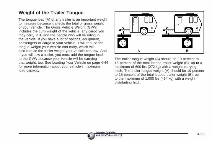
Weight of the Trailer TongueThe tongue load (A) of any trailer is an important weightto measure because it affects the total or gross weightof your vehicle. The Gross Vehicle Weight (GVW)includes the curb weight of the vehicle, any cargo youmay carry in it, and the people who will be riding inthe vehicle. If you have a lot of options, equipment,passengers or cargo in your vehicle, it will reduce thetongue weight your vehicle can carry, which willalso reduce the trailer weight your vehicle can tow. Andif you will tow a trailer, you must add the tongue loadto the GVW because your vehicle will be carryingthat weight, too. See Loading Your Vehicle on page 4-44for more information about your vehicle’s maximumload capacity.
The trailer tongue weight (A) should be 10 percent to15 percent of the total loaded trailer weight (B), up to amaximum of 600 lbs (272 kg) with a weight carryinghitch. The trailer tongue weight (A) should be 10 percentto 15 percent of the total loaded trailer weight (B), upto the maximum of 1,000 lbs (454 kg) with a weightdistributing hitch.
4-55Information Provided by:

Do not exceed the maximum allowable tongue weightfor your vehicle. Choose the shortest hitch extensionthat will position the hitch ball closest to the vehicle.This will help reduce the effect of trailer tongue weighton the rear axle.
After you’ve loaded your trailer, weigh the trailer andthen the tongue, separately, to see if the weightsare proper. If they aren’t, you may be able to getthem right simply by moving some items around inthe trailer.
Trailering may be limited by the vehicle’s ability to carrytongue weight. Tongue weight cannot cause thevehicle to exceed the GVWR (Gross Vehicle WeightRating) or the RGAWR (Rear Gross Axle WeightRating). The effect of additional weight may reduceyour trailering capacity more than the total of theadditional weight.
Consider the following example:
A vehicle model base weight is 5,500 lbs (2 495 kg);2,800 lbs (1 270 kg) at the front axle and 2,700 lbs(1 225 kg) at the rear axle. It has a GVWR of 7,200 lbs(3 266 kg), a RGAWR of 4,000 lbs (1 814 kg) and aGCWR (Gross Combination Weight Rating) of14,000 lbs (6 350 kg). The trailer rating should be:
You can expect tongue weight to be at least 10 percentof trailer weight (850 lbs (386 kg)) and because theweight is applied well behind the rear axle, the effect onthe rear axle will be greater than just the weightitself, as much as 1.5 times as much. The weight at therear axle could be 850 lbs (386 kg) X 1.5 = 1,275 lbs(578 kg). Since the rear axle already weighs 2,700 lbs(1 225 kg), adding 1,275 lbs (578 kg) brings thetotal to 3,975 lbs (1 803 kg). This is very close to, butwithin the limit for RGAWR as well. The vehicle is set totrailer up to 8,500 lbs (3 856 kg).
4-56Information Provided by:

But let’s say your specific vehicle is equipped with someof the latest options and you have a front seat passengerand two rear seat passengers with some luggage andgear in the vehicle as well. You may add 300 lbs (136 kg)to the front axle weight and 400 lbs (181 kg) to the rearaxle weight. Your vehicle now weighs:
Weight is still below 7,200 lbs (3 266 kg) and you maythink that you should subtract 700 additional pounds(318 kg) from your trailering capacity to stay withinGCWR limits. Your maximum trailer would only be7,800 lbs (3 538 kg). You may go further and think youmust limit tongue weight to less than 1,000 lbs (454 kg) toavoid exceeding GVWR. But, you must still consider theeffect on the rear axle. Because your rear axle nowweighs 3,100 lbs (1 406 kg), you can only put 900 lbs(408 kg) on the rear axle without exceeding RGAWR. Theeffect of tongue weight is about 1.5 times the actualweight. Dividing the 900 lbs (408 kg) by 1.5 leaves you
with being able to handle only 600 lbs (272 kg) of tongueweight. Since tongue weight is usually at least 10 percentof total loaded trailer weight, you can expect that thelargest trailer your vehicle can properly handle is6,000 lbs (2 721 kg).
It is important that you make sure your vehicle does notexceed any of its ratings — GCWR, GVWR, RGAWR,Maximum Trailer Rating or Tongue Weight. Theonly way to be sure you are not exceeding any of theseratings is to weigh your vehicle and trailer.
Total Weight on Your Vehicle’s TiresBe sure your vehicle’s tires are inflated to the upper limitfor cold tires. You’ll find these numbers on theCertification label at the rear edge of the driver’s door orsee Loading Your Vehicle on page 4-44. Then besure you don t go over the GVW limit for your vehicle,or the GAWR, including the weight of the trailertongue. If you use a weight distributing hitch, make sureyou don’t go over the rear axle limit before you applythe weight distribution spring bars.
HitchesIt’s important to have the correct hitch equipment.Crosswinds, large trucks going by and rough roads area few reasons why you’ll need the right hitch.
4-57Information Provided by:

Weight-Distributing Hitches and WeightCarrying Hitches
When using a weight-distributing hitch, the hitch mustbe adjusted so that the distance (A) remains thesame both before and after coupling the trailer to thetow vehicle.
If you’ll be pulling a trailer that, when loaded, will weighmore than 5,000 lbs (2 270 kg) be sure to use aproperly mounted weight-distributing hitch and swaycontrol of the proper size. This equipment is veryimportant for proper vehicle loading and good handlingwhen driving. You should always use a sway controlif your trailer will weigh more than these limits. You canask a hitch dealer about sway controls.
Safety ChainsYou should always attach chains between your vehicleand your trailer. Cross the safety chains under thetongue of the trailer to help prevent the tongue fromcontacting the road if it becomes separated fromthe hitch. Always leave just enough slack so you canturn with your rig. Never allow safety chains to drag onthe ground.
Trailer BrakesIf your trailer weighs more than 2,000 lbs (900 kg)loaded, then it needs its own brakes – and they must beadequate. Be sure to read and follow the instructionsfor the trailer brakes so you’ll be able to install,adjust and maintain them properly.
Since your vehicle is equipped with StabiliTrak®, yourtrailer brake system cannot tap into the vehicle’shydraulic brake system.
(A) Body-to-Ground Distance (B) Front of Vehicle
4-58Information Provided by:

Driving with a TrailerTowing a trailer requires a certain amount of experience.Before setting out for the open road, you’ll want to getto know your rig. Acquaint yourself with the feel ofhandling and braking with the added weight of the trailer.And always keep in mind that the vehicle you aredriving is now a good deal longer and not nearly asresponsive as your vehicle is by itself.
Before you start, check all trailer hitch parts andattachments, safety chains, electrical connector, lamps,tires and mirror adjustment. If the trailer has electricbrakes, start your vehicle and trailer moving and thenapply the trailer brake controller by hand to be surethe brakes are working. This lets you check yourelectrical connection at the same time.
During your trip, check occasionally to be sure that theload is secure, and that the lamps and any trailerbrakes are still working.
Following DistanceStay at least twice as far behind the vehicle ahead asyou would when driving your vehicle without a trailer.This can help you avoid situations that requireheavy braking and sudden turns.
PassingYou’ll need more passing distance up ahead whenyou’re towing a trailer. And, because you’re a good deallonger, you’ll need to go much farther beyond thepassed vehicle before you can return to your lane.
Backing UpHold the bottom of the steering wheel with one hand.Then, to move the trailer to the left, just move that handto the left. To move the trailer to the right, move yourhand to the right. Always back up slowly and, if possible,have someone guide you.
Making Turns
Notice: Making very sharp turns while traileringcould cause the trailer to come in contact with thevehicle. Your vehicle could be damaged. Avoidmaking very sharp turns while trailering.
When you’re turning with a trailer, make wider turns thannormal. Do this so your trailer won’t strike soft shoulders,curbs, road signs, trees or other objects. Avoid jerky orsudden maneuvers. Signal well in advance.
4-59Information Provided by:
Turn Signals When Towing a TrailerThe arrows on your instrument panel will flash wheneveryou signal a turn or lane change. Properly hooked up,the trailer lamps will also flash, telling other driversyou’re about to turn, change lanes or stop.
When towing a trailer, the arrows on your instrumentpanel will flash for turns even if the bulbs on the trailerare burned out. Thus, you may think drivers behindyou are seeing your signal when they are not. It’simportant to check occasionally to be sure the trailerbulbs are still working.
Driving On GradesReduce speed and shift to a lower gear before you startdown a long or steep downgrade. If you don’t shiftdown, you might have to use your brakes so much thatthey would get hot and no longer work well.
You can tow in DRIVE (D). You may want to shiftthe transmission to THIRD (3) or, if necessary, a lowergear selection if the transmission shifts too often(e.g., under heavy loads and/or hilly conditions).
You may also want to activate the tow/haul mode ifthe transmission shifts too often. See “Tow/HaulMode” earlier.
When towing at high altitude on steep uphill grades,consider the following: Engine coolant at or nearsea level will boil at a lower temperature than at higheraltitudes. If you turn your engine off immediatelyafter towing at high altitude on steep uphill grades, yourvehicle may show signs similar to engine overheating.To avoid this, let the engine run while parked (preferablyon level ground) with the automatic transmission inPARK (P) for a few minutes before turning the engineoff. If you do get the overheat warning, see EngineOverheating on page 5-26.
4-60Information Provided by:
Parking on Hills
{CAUTION:
You really should not park your vehicle, with atrailer attached, on a hill. If something goeswrong, your rig could start to move. Peoplecan be injured, and both your vehicle and thetrailer can be damaged.
But if you ever have to park your rig on a hill, here’show to do it:
1. Apply your regular brakes, but don’t shift intoPARK (P) yet.
2. Have someone place chocks under thetrailer wheels.
3. When the wheel chocks are in place, release theregular brakes until the chocks absorb the load.
4. Reapply the regular brakes. Then apply yourparking brake and shift into PARK (P).
5. Release the regular brakes.
When You Are Ready to Leave AfterParking on a Hill
1. Apply your regular brakes and hold the pedal downwhile you:
• start your engine,
• shift into a gear, and
• release the parking brake.
2. Let up on the brake pedal.
3. Drive slowly until the trailer is clear of the chocks.
4. Stop and have someone pick up and storethe chocks.
Maintenance When Trailer TowingYour vehicle will need service more often when you’repulling a trailer. See the Maintenance Schedule for moreon this. Things that are especially important in traileroperation are automatic transmission fluid (don’t overfill),engine oil, axle lubricant, belts, cooling system and brakesystem. Each of these is covered in this manual, and theIndex will help you find them quickly. If you’re trailering,it’s a good idea to review these sections before you startyour trip.
Check periodically to see that all hitch nuts and boltsare tight.
4-61Information Provided by:

Trailer Wiring HarnessHeavy-Duty Trailer Wiring Package
Your vehicle is equipped with the seven-wire trailertowing harness. This harness with a seven-pin universalheavy-duty trailer connector is attached to a bracketon the hitch platform.
The Center High-Mounted Stoplamp (CHMSL) wireis tied next to the trailer wiring harness for use witha trailer.
The seven-wire harness contains the followingtrailer circuits:
• Yellow: Left Stop/Turn Signal
• Dark Green: Right Stop/Turn Signal
• Brown: Taillamps
• White: Ground
• Light Green: Back-up Lamps
• Red: Battery Feed
• Dark Blue: Trailer Brake
4-62Information Provided by:

Electric Brake Control Jumper
This harness may be included with your vehicle as partof the heavy-duty trailer wiring package.
This harness is for an electric brake controller andincludes a trailer battery feed fuse. It should be installedby your dealer or a qualified service center.
Trailer RecommendationsYou must subtract your hitch loads from the CargoWeight Rating (CWR). CWR is the maximum weight ofthe load your vehicle can carry. It doesn’t includethe weight of the people inside, but you can figure about150 lbs. (68 kg) for each seat. The total cargo loadmust not be more than your vehicles CWR.
Weigh your vehicle with your trailer attached, so thatyou won’t go over the GVWR or GAWR. If you are usinga weight-distributing hitch, weigh the vehicle withoutthe spring bars in place.
You’ll get the best performance if you spread out theweight of your load the right way, and if you choose thecorrect hitch and trailer brakes.
For more information see Towing a Trailer on page 4-50.
4-63Information Provided by:

✍ NOTES
4-64Information Provided by:

Service ............................................................5-3Accessories and Modifications ..........................5-3California Proposition 65 Warning .....................5-3Doing Your Own Service Work .........................5-4Adding Equipment to the Outside of
Your Vehicle ..............................................5-4Fuel ................................................................5-5
Gasoline Octane ............................................5-5Gasoline Specifications ....................................5-5California Fuel ...............................................5-6Additives .......................................................5-6Fuels in Foreign Countries ...............................5-7Filling the Tank ..............................................5-8Filling a Portable Fuel Container .....................5-10
Checking Things Under the Hood ....................5-10Hood Release ..............................................5-11Engine Compartment Overview .......................5-12Engine Oil ...................................................5-14Engine Oil Life System ..................................5-17Engine Air Cleaner/Filter ................................5-19Automatic Transmission Fluid .........................5-21Engine Coolant .............................................5-24Coolant Surge Tank Pressure Cap ..................5-26Engine Overheating .......................................5-26Overheated Engine Protection
Operating Mode ........................................5-28Cooling System ............................................5-28
Engine Fan Noise .........................................5-33Power Steering Fluid .....................................5-34Windshield Washer Fluid ................................5-35Brakes ........................................................5-36Battery ........................................................5-39Jump Starting ...............................................5-40
All-Wheel Drive ..............................................5-45Rear Axle .......................................................5-46Front Axle ......................................................5-47Headlamp Aiming ...........................................5-48
Headlamp Horizontal Aiming ...........................5-49Headlamp Vertical Aiming ..............................5-50
Bulb Replacement ..........................................5-52High Intensity Discharge (HID) Lighting ............5-52Halogen Bulbs ..............................................5-52Headlamps ..................................................5-53Front Turn Signal, Sidemarker and
Daytime Running Lamps .............................5-56Taillamps, Turn Signal, Stoplamps and
Back-up Lamps .........................................5-57Replacement Bulbs .......................................5-58
Windshield Wiper Blade Replacement ..............5-59Tires ..............................................................5-60
Tire Sidewall Labeling ...................................5-61Tire Terminology and Definitions .....................5-64Inflation - Tire Pressure .................................5-66
Section 5 Service and Appearance Care
5-1Information Provided by:

Tire Pressure Monitor System .........................5-69Tire Inspection and Rotation ...........................5-72When It Is Time for New Tires .......................5-74Buying New Tires .........................................5-74Different Size Tires and Wheels ......................5-76Uniform Tire Quality Grading ..........................5-76Wheel Alignment and Tire Balance ..................5-78Wheel Replacement ......................................5-78Tire Chains ..................................................5-79If a Tire Goes Flat ........................................5-80Changing a Flat Tire .....................................5-81Removing the Spare Tire and Tools ................5-82Removing the Flat Tire and Installing the
Spare Tire ................................................5-86Secondary Latch System ...............................5-93Storing a Flat or Spare Tire and Tools ............5-96Spare Tire ...................................................5-99
Appearance Care ..........................................5-100Cleaning the Inside of Your Vehicle ...............5-100Fabric/Carpet ..............................................5-101Leather ......................................................5-102Instrument Panel, Vinyl, and Other
Plastic Surfaces .......................................5-102Wood Panels ..............................................5-103Speaker Covers ..........................................5-103Care of Safety Belts ....................................5-103
Weatherstrips .............................................5-103Washing Your Vehicle ..................................5-103Cleaning Exterior Lamps/Lenses ....................5-104Finish Care ................................................5-104Windshield and Wiper Blades .......................5-105Aluminum or Chrome-Plated Wheels ..............5-105Tires .........................................................5-106Sheet Metal Damage ...................................5-106Finish Damage ...........................................5-106Underbody Maintenance ...............................5-106Chemical Paint Spotting ...............................5-106Vehicle Care/Appearance Materials ................5-107
Vehicle Identification .....................................5-108Vehicle Identification Number (VIN) ................5-108Service Parts Identification Label ...................5-108
Electrical System ..........................................5-109Add-On Electrical Equipment .........................5-109Windshield Wiper Fuses ...............................5-109Power Windows and Other Power Options ......5-109Fuses and Circuit Breakers ..........................5-109Instrument Panel Fuse Block ........................5-110Center Instrument Panel Fuse Block ..............5-112Underhood Fuse Block ................................5-113
Capacities and Specifications ........................5-119
Section 5 Service and Appearance Care
5-2Information Provided by:

ServiceYour dealer knows your vehicle best and wants you tobe happy with it. We hope you will go to your dealerfor all your service needs. You will get genuine GM partsand GM-trained and supported service people.
We hope you will want to keep your GM vehicle all GM.Genuine GM parts have one of these marks:
Accessories and ModificationsWhen you add non-GM accessories to your vehicle theycan affect your vehicle’s performance and safety,including such things as, braking, stability, ride andhandling, emissions systems, aerodynamics, durability,and electronic systems like antilock brakes, tractioncontrol and stability control. Some of these accessoriesmay even cause malfunction or damage not coveredby warranty.
GM Accessories are designed to complement andfunction with other systems on your vehicle. Your GMdealer can accessorize your vehicle using genuineGM Accessories. When you go to your GM dealer andask for GM Accessories, you will know that GM-trainedand supported service technicians will perform thework using genuine GM Accessories.
California Proposition 65 WarningMost motor vehicles, including this one, contain and/oremit chemicals known to the State of California tocause cancer and birth defects or other reproductiveharm. Engine exhaust, many parts and systems(including some inside the vehicle), many fluids, andsome component wear by-products contain and/or emitthese chemicals.
5-3Information Provided by:

Doing Your Own Service Work
{CAUTION:
You can be injured and your vehicle could bedamaged if you try to do service work on avehicle without knowing enough about it.
• Be sure you have sufficient knowledge,experience, the proper replacement parts,and tools before you attempt any vehiclemaintenance task.
• Be sure to use the proper nuts, bolts, andother fasteners. English and metricfasteners can be easily confused. If youuse the wrong fasteners, parts can laterbreak or fall off. You could be hurt.
If you want to do some of your own service work, youwill want to use the proper service manual. It tellsyou much more about how to service your vehicle thanthis manual can. To order the proper service manual,see Service Publications Ordering Information onpage 7-14.
Your vehicle has an airbag system. Before attemptingto do your own service work, see Servicing YourAirbag-Equipped Vehicle on page 1-64.
You should keep a record with all parts receipts andlist the mileage and the date of any service workyou perform. See Maintenance Record on page 6-15.
Adding Equipment to the Outsideof Your VehicleThings you might add to the outside of your vehiclecan affect the airflow around it. This may causewind noise and affect windshield washer performance.Check with your dealer before adding equipment tothe outside of your vehicle.
5-4Information Provided by:

FuelUse of the recommended fuel is an important part of theproper maintenance of your vehicle.
Gasoline OctaneUse premium unleaded gasoline with a posted octanerating of 91 or higher. You may also use regularunleaded gasoline rated at 87 octane or higher, butyour vehicle’s acceleration may be slightly reduced,and you may notice a slight audible knocking noise,commonly referred to as spark knock. If the octane isless than 87, you may notice a heavy knockingnoise when you drive. If this occurs, use a gasolinerated at 87 octane or higher as soon as possible.Otherwise, you might damage your engine. If you areusing gasoline rated at 87 octane or higher and you hearheavy knocking, your engine needs service.
Gasoline SpecificationsAt a minimum, gasoline should meet ASTMspecification D 4814 in the United States orCAN/CGSB-3.5 in Canada. Some gasolines maycontain an octane-enhancing additive calledmethylcyclopentadienyl manganese tricarbonyl (MMT).General Motors recommends against the use ofgasolines containing MMT. See Additives on page 5-6for additional information.
5-5Information Provided by:

California FuelIf your vehicle is certified to meet California EmissionsStandards, it is designed to operate on fuels thatmeet California specifications. See the underhoodemission control label. If this fuel is not availablein states adopting California emissions standards,your vehicle will operate satisfactorily on fuels meetingfederal specifications, but emission control systemperformance may be affected. The malfunction indicatorlamp may turn on and your vehicle may fail asmog-check test. See Malfunction Indicator Lamp onpage 3-39. If this occurs, return to your authorizedGM dealer for diagnosis. If it is determined thatthe condition is caused by the type of fuel used,repairs may not be covered by your warranty.
AdditivesTo provide cleaner air, all gasolines in the United Statesare now required to contain additives that will helpprevent engine and fuel system deposits from forming,allowing your emission control system to work properly.In most cases, you should not have to add anythingto your fuel. However, some gasolines contain only theminimum amount of additive required to meet U.S.Environmental Protection Agency regulations. To helpkeep fuel injectors and intake valves clean, or ifyour vehicle experiences problems due to dirty injectorsor valves, look for gasoline that is advertised asTOP TIER Detergent Gasoline. Also, your GM dealerhas additives that will help correct and prevent mostdeposit-related problems.
Gasolines containing oxygenates, such as ethers andethanol, and reformulated gasolines may be available inyour area. General Motors recommends that you usethese gasolines if they comply with the specificationsdescribed earlier. However, E85 (85% ethanol)and other fuels containing more than 10% ethanol mustnot be used in vehicles that were not designed forthose fuels.
5-6Information Provided by:
Notice: Your vehicle was not designed for fuel thatcontains methanol. Do not use fuel containingmethanol. It can corrode metal parts in your fuelsystem and also damage the plastic and rubberparts. That damage would not be covered underyour warranty.
Some gasolines that are not reformulated for lowemissions may contain an octane-enhancing additivecalled methylcyclopentadienyl manganese tricarbonyl(MMT); ask the attendant where you buy gasolinewhether the fuel contains MMT. General Motorsrecommends against the use of such gasolines.Fuels containing MMT can reduce the life of spark plugsand the performance of the emission control systemmay be affected. The malfunction indicator lampmay turn on. If this occurs, return to your authorizedGM dealer for service.
Fuels in Foreign CountriesIf you plan on driving in another country outside theUnited States or Canada, the proper fuel may be hardto find. Never use leaded gasoline or any other fuelnot recommended in the previous text on fuel.Costly repairs caused by use of improper fuel would notbe covered by your warranty.
To check the fuel availability, ask an auto club, orcontact a major oil company that does business in thecountry where you will be driving.
5-7Information Provided by:

Filling the Tank
{CAUTION:
Fuel vapor burns violently and a fuel fire cancause bad injuries. To help avoid injuries to youand others, read and follow all the instructionson the pump island. Turn off your engine whenyou are refueling. Do not smoke if you are nearfuel or refueling your vehicle. Keep sparks,flames, and smoking materials away from fuel.Do not leave the fuel pump unattended whenrefueling your vehicle — this is against the lawin some places. Keep children away from thefuel pump; never let children pump fuel.
The tethered fuel cap is located behind a hinged fueldoor on the driver’s side of the vehicle.
To remove the fuel cap, turn it slowly counterclockwise.It will require more effort to turn the fuel cap on thelast turn as you loosen it.
{CAUTION:
If you spill fuel and then something ignites it,you could be badly burned. Fuel can spray outon you if you open the fuel cap too quickly.This spray can happen if your tank is nearlyfull, and is more likely in hot weather. Openthe fuel cap slowly and wait for any hiss noiseto stop. Then unscrew the cap all the way.
5-8Information Provided by:

Be careful not to spill fuel. Do not top off or overfill thetank and wait a few seconds after you have finishedpumping before removing the nozzle. Clean fuelfrom painted surfaces as soon as possible.See Washing Your Vehicle on page 5-103.
When replacing the fuel cap, turn it clockwise until itclicks. It will require more effort to turn the fuel cap onthe last turn as you tighten it. Make sure the cap isfully installed. The diagnostic system can determine ifthe fuel cap has been left off or improperly installed.This would allow fuel to evaporate into the atmosphere.See Malfunction Indicator Lamp on page 3-39.
The TIGHTEN FUEL CAP message will be displayed onthe Driver Information Center (DIC) if the fuel cap isnot properly installed. See DIC Warnings and Messageson page 3-48 for more information.
{CAUTION:
If a fire starts while you are refueling, do notremove the nozzle. Shut off the flow of fuel byshutting off the pump or by notifying thestation attendant. Leave the area immediately.
Notice: If you need a new fuel cap, be sure to getthe right type. Your dealer can get one for you.If you get the wrong type, it may not fit properly.This may cause your malfunction indicator lamp tolight and may damage your fuel tank and emissionssystem. See Malfunction Indicator Lamp onpage 3-39.
5-9Information Provided by:
Filling a Portable Fuel Container
{CAUTION:
Never fill a portable fuel container while it is inyour vehicle. Static electricity discharge fromthe container can ignite the gasoline vapor.You can be badly burned and your vehicledamaged if this occurs. To help avoid injury toyou and others:
• Dispense gasoline only into approvedcontainers.
• Do not fill a container while it is inside avehicle, in a vehicle’s trunk, pickup bed, oron any surface other than the ground.
• Bring the fill nozzle in contact with theinside of the fill opening before operatingthe nozzle. Contact should be maintaineduntil the filling is complete.
• Do not smoke while pumping gasoline.
Checking Things Underthe Hood
{CAUTION:
An electric fan under the hood can start upand injure you even when the engine is notrunning. Keep hands, clothing and tools awayfrom any underhood electric fan.
{CAUTION:
Things that burn can get on hot engine partsand start a fire. These include liquids like fuel,oil, coolant, brake fluid, windshield washer andother fluids, and plastic or rubber. You orothers could be burned. Be careful not to dropor spill things that will burn onto a hot engine.
5-10Information Provided by:

Hood ReleaseTo open the hood do the following:
1. Pull the handle withthis symbol on it. It islocated inside thevehicle to the lower leftof the steering wheel.
2. Then go to the front of the vehicle and pull up onthe secondary hood release located near thecenter of the grille.
3. Lift the hood.Before closing the hood, be sure all the filler capsare on properly. Then pull down the hood and closeit firmly.
5-11Information Provided by:
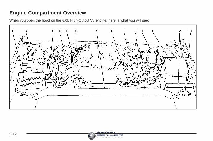
Engine Compartment OverviewWhen you open the hood on the 6.0L High-Output V8 engine, here is what you will see:
5-12Information Provided by:
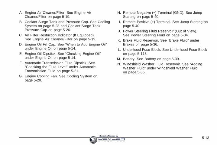
A. Engine Air Cleaner/Filter. See Engine AirCleaner/Filter on page 5-19.
B. Coolant Surge Tank and Pressure Cap. See CoolingSystem on page 5-28 and Coolant Surge TankPressure Cap on page 5-26.
C. Air Filter Restriction Indicator (If Equipped).See Engine Air Cleaner/Filter on page 5-19.
D. Engine Oil Fill Cap. See “When to Add Engine Oil”under Engine Oil on page 5-14.
E. Engine Oil Dipstick. See “Checking Engine Oil”under Engine Oil on page 5-14.
F. Automatic Transmission Fluid Dipstick. See“Checking the Fluid Level” under AutomaticTransmission Fluid on page 5-21.
G. Engine Cooling Fan. See Cooling System onpage 5-28.
H. Remote Negative (−) Terminal (GND). See JumpStarting on page 5-40.
I. Remote Positive (+) Terminal. See Jump Starting onpage 5-40.
J. Power Steering Fluid Reservoir (Out of View).See Power Steering Fluid on page 5-34.
K. Brake Fluid Reservoir. See “Brake Fluid” underBrakes on page 5-36.
L. Underhood Fuse Block. See Underhood Fuse Blockon page 5-113.
M. Battery. See Battery on page 5-39.N. Windshield Washer Fluid Reservoir. See “Adding
Washer Fluid” under Windshield Washer Fluidon page 5-35.
5-13Information Provided by:

Engine OilIf the CHECK OIL LEVEL message appears on theDriver Information Center (DIC), it means you need tocheck your engine oil level right away. For moreinformation, see CHECK OIL LEVEL underDIC Warnings and Messages on page 3-48.
You should check your engine oil level regularly;this is an added reminder.
Checking Engine OilIt is a good idea to check your engine oil every time youget fuel. In order to get an accurate reading, the oilmust be warm and the vehicle must be on level ground.
The engine oil dipstick handle is a yellow loop.See Engine Compartment Overview on page 5-12for the location of the engine oil dipstick.
1. Turn off the engine and give the oil several minutesto drain back into the oil pan. If you do not do this,the oil dipstick might not show the actual level.
2. Pull out the dipstick and clean it with a paper towelor cloth, then push it back in all the way. Remove itagain, keeping the tip down, and check the level.
5-14Information Provided by:

When to Add Engine Oil
If the oil is below the cross-hatched area at the tip of thedipstick, you will need to add at least one quart/liter of oil.But you must use the right kind. This section explainswhat kind of oil to use. For engine oil crankcase capacity,see Capacities and Specifications on page 5-119.
Notice: Do not add too much oil. If the engine hasso much oil that the oil level gets above thecross-hatched area that shows the proper operatingrange, the engine could be damaged.
See Engine CompartmentOverview on page 5-12for the location of theengine oil fill cap.
Be sure to add enough oil to put the level somewherein the proper operating range. Push the dipstick allthe way back in when you are through.
5-15Information Provided by:
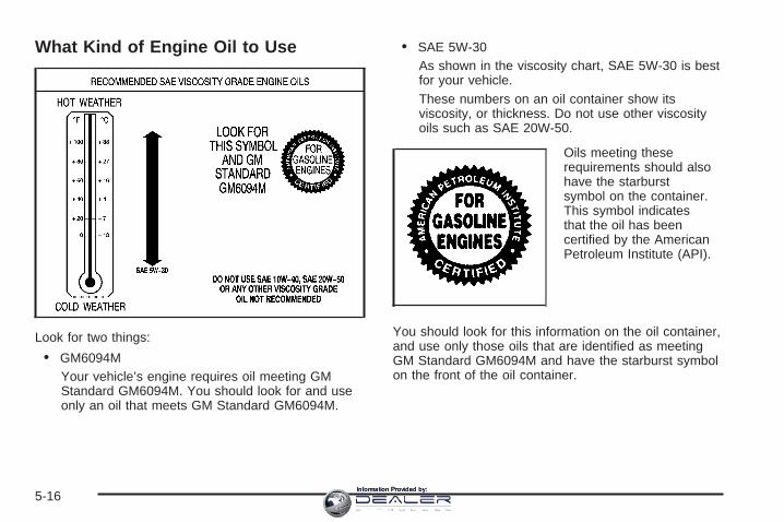
What Kind of Engine Oil to Use
Look for two things:
• GM6094MYour vehicle’s engine requires oil meeting GMStandard GM6094M. You should look for and useonly an oil that meets GM Standard GM6094M.
• SAE 5W-30As shown in the viscosity chart, SAE 5W-30 is bestfor your vehicle.These numbers on an oil container show itsviscosity, or thickness. Do not use other viscosityoils such as SAE 20W-50.
Oils meeting theserequirements should alsohave the starburstsymbol on the container.This symbol indicatesthat the oil has beencertified by the AmericanPetroleum Institute (API).
You should look for this information on the oil container,and use only those oils that are identified as meetingGM Standard GM6094M and have the starburst symbolon the front of the oil container.
5-16Information Provided by:
Notice: Use only engine oil identified as meetingGM Standard GM6094M and showing the AmericanPetroleum Institute Certified For Gasoline Enginesstarburst symbol. Failure to use the recommendedoil can result in engine damage not covered byyour warranty.
GM Goodwrench® oil meets all the requirements foryour vehicle.
If you are in an area of extreme cold, where thetemperature falls below −20°F (−29°C), it isrecommended that you use either an SAE 5W-30synthetic oil or an SAE 0W-30 oil. Both will provideeasier cold starting and better protection for your engineat extremely low temperatures.
Engine Oil AdditivesDo not add anything to your oil. The recommended oilswith the starburst symbol that meet GM StandardGM6094M are all you will need for good performanceand engine protection.
Engine Oil Life SystemWhen to Change Engine OilYour vehicle has a computer system that lets you knowwhen to change the engine oil and filter. This is basedon engine revolutions and engine temperature, and noton mileage. Based on driving conditions, the mileageat which an oil change will be indicated can varyconsiderably. For the oil life system to work properly,you must reset the system every time the oil is changed.
When the system has calculated that oil life has beendiminished, it will indicate that an oil change isnecessary. A CHANGE ENGINE OIL message willcome on. Change your oil as soon as possible withinthe next 600 miles (1 000 km). It is possible that, if youare driving under the best conditions, the oil lifesystem may not indicate that an oil change is necessaryfor over a year. However, your engine oil and filtermust be changed at least once a year and at this timethe system must be reset. Your dealer has GM-trainedservice people who will perform this work usinggenuine GM parts and reset the system. It is alsoimportant to check your oil regularly and keep it at theproper level.
If the system is ever reset accidentally, you mustchange your oil at 3,000 miles (5 000 km) since yourlast oil change. Remember to reset the oil life systemwhenever the oil is changed.
5-17Information Provided by:

How to Reset the Engine Oil LifeSystemThe Engine Oil Life System calculates when to changeyour engine oil and filter based on vehicle use.Anytime your oil is changed, reset the system so it cancalculate when the next oil change is required. If asituation occurs where you change your oil prior to aCHANGE ENGINE OIL message being turned on, resetthe system.
To reset the CHANGE ENGINE OIL message, see“Engine Oil Life System” under DIC Operation andDisplays on page 3-45 for vehicles equipped with theDIC, or do the following:
1. Turn the ignition key to RUN with the engine off.
2. Fully press and release the accelerator pedalslowly three times within five seconds.If the OIL LIFE RESET message flashes for10 seconds, the system is resetting.
3. Turn the key to LOCK.
If the CHANGE ENGINE OIL message comes back onwhen you start your vehicle, the engine oil life systemhas not reset. Repeat the procedure. If it still doesnot reset, see your dealer for service.
What to Do with Used OilUsed engine oil contains certain elements that may beunhealthy for your skin and could even cause cancer.Do not let used oil stay on your skin for very long.Clean your skin and nails with soap and water, or agood hand cleaner. Wash or properly dispose ofclothing or rags containing used engine oil. See themanufacturer’s warnings about the use and disposal ofoil products.
Used oil can be a threat to the environment. If youchange your own oil, be sure to drain all the oil fromthe filter before disposal. Never dispose of oil by puttingit in the trash, pouring it on the ground, into sewers,or into streams or bodies of water. Instead, recycle it bytaking it to a place that collects used oil. If you havea problem properly disposing of your used oil,ask your dealer, a service station or a local recyclingcenter for help.
5-18Information Provided by:

Engine Air Cleaner/FilterSee Engine CompartmentOverview on page 5-12for the location of theengine air cleaner/filterand the air filter restrictionindicator, if equipped.
When to Inspect the EngineAir Cleaner/FilterIf your vehicle is equipped with an air filter restrictionindicator, it lets you know when the engine aircleaner/filter needs to be replaced. On vehicles with arestriction indicator, you should inspect the air filterrestriction indicator at every oil change and replace theengine air cleaner/filter when the indicator tells you to.
On vehicles without an air filter restriction indicator,inspect the air cleaner/filter at the Maintenance IIintervals and replace it at the first oil change aftereach 50,000 mile (83 000 km) interval. See ScheduledMaintenance on page 6-4 for more information.If you are driving in dusty/dirty conditions, inspect thefilter at each engine oil change.
How to Inspect the Engine AirCleaner/Filter
Vehicles With an Air Filter RestrictionIndicatorLocate the air filter restriction indicator on the engine aircleaner/filter cover. When the indicator turns black oris in the red/orange “change” zone, replace the filter andreset the indicator. See the steps following to replacethe engine air cleaner/filter and to reset the air filterrestriction indicator.
Vehicles Without an Air Filter RestrictionIndicatorTo inspect the air cleaner/filter, remove the engine aircleaner/filter from the vehicle using the steps following.When you have the engine air cleaner/filter removed,lightly shake it to release loose dust and dirt. If theengine air cleaner/filter remains caked with dirt, a newfilter is required.
5-19Information Provided by:
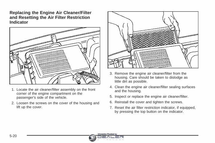
Replacing the Engine Air Cleaner/Filterand Resetting the Air Filter RestrictionIndicator
1. Locate the air cleaner/filter assembly on the frontcorner of the engine compartment on thepassenger’s side of the vehicle.
2. Loosen the screws on the cover of the housing andlift up the cover.
3. Remove the engine air cleaner/filter from thehousing. Care should be taken to dislodge aslittle dirt as possible.
4. Clean the engine air cleaner/filter sealing surfacesand the housing.
5. Inspect or replace the engine air cleaner/filter.
6. Reinstall the cover and tighten the screws.
7. Reset the air filter restriction indicator, if equipped,by pressing the top button on the indicator.
5-20Information Provided by:

{CAUTION:
Operating the engine with the air cleaner/filteroff can cause you or others to be burned.The air cleaner not only cleans the air; it helpsto stop flames if the engine backfires. If it isnot there and the engine backfires, you couldbe burned. Do not drive with it off, and becareful working on the engine with the aircleaner/filter off.
Automatic Transmission FluidWhen to Check and ChangeAutomatic Transmission FluidA good time to check your automatic transmission fluidlevel is when the engine oil is changed.
Change the fluid and filter at the intervals listed inAdditional Required Services on page 6-6, and be sureto use the transmission fluid listed in RecommendedFluids and Lubricants on page 6-12.
How to Check AutomaticTransmission FluidBecause this operation can be a little difficult, you maychoose to have this done at the dealership servicedepartment.
If you do it yourself, be sure to follow all the instructionshere, or you could get a false reading on the dipstick.
Notice: Too much or too little fluid can damageyour transmission. Too much can mean that someof the fluid could come out and fall on hot enginepart or exhaust system parts, starting a fire.Too little fluid could cause the transmission tooverheat. Be sure to get an accurate reading if youcheck your transmission fluid.
Wait at least 30 minutes before checking thetransmission fluid level if you have been driving:
• When outside temperatures are above 90°F (32°C).
• At high speed for quite a while.
• In heavy traffic — especially in hot weather.
• While pulling a trailer.
5-21Information Provided by:

To get the right reading, the fluid should be at normaloperating temperature, which is 180°F to 200°F(82°C to 93°C).
Get the vehicle warmed up by driving about 15 miles(24 km) when outside temperatures are above50°F (10°C). If it is colder than 50°F (10°C), drive thevehicle in THIRD (3) until the engine temperaturegage moves and then remains steady for 10 minutes.
A cold fluid check can be made after the vehiclehas been sitting for eight hours or more with the engineoff, but this is used only as a reference. Let theengine run at idle for five minutes if outsidetemperatures are 50°F (10°C) or more. If it is colderthan 50°F (10°C), you may have to idle the enginelonger. Should the fluid level be low during this coldcheck, you must check the fluid hot before adding fluid.Checking the fluid hot will give you a more accuratereading of the fluid level.
Checking the Fluid LevelPrepare your vehicle as follows:
1. Park your vehicle on a level place. Keep the enginerunning.
2. With the parking brake applied, place the shift leverin PARK (P).
3. With your foot on the brake pedal, move the shiftlever through each gear range, pausing for aboutthree seconds in each range. Then, positionthe shift lever in PARK (P).
4. Let the engine run at idle for three minutes or more.
Then, without shutting off the engine, follow these steps:
The transmission dipstickhandle with this graphic islocated at the rear ofthe engine compartment,on the passenger’sside of the vehicle.
See Engine Compartment Overview on page 5-12for more information on location.
1. Flip the handle up and then pull out the dipstickand wipe it with a clean rag or paper towel.
2. Push it back in all the way, wait three seconds andthen pull it back out again.
5-22Information Provided by:
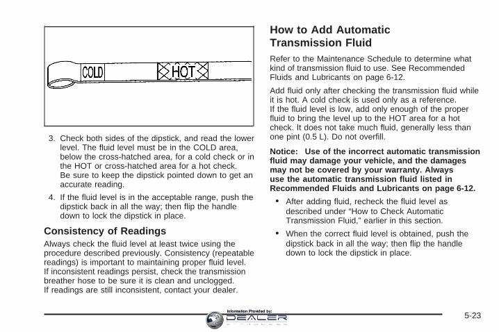
3. Check both sides of the dipstick, and read the lowerlevel. The fluid level must be in the COLD area,below the cross-hatched area, for a cold check or inthe HOT or cross-hatched area for a hot check.Be sure to keep the dipstick pointed down to get anaccurate reading.
4. If the fluid level is in the acceptable range, push thedipstick back in all the way; then flip the handledown to lock the dipstick in place.
Consistency of ReadingsAlways check the fluid level at least twice using theprocedure described previously. Consistency (repeatablereadings) is important to maintaining proper fluid level.If inconsistent readings persist, check the transmissionbreather hose to be sure it is clean and unclogged.If readings are still inconsistent, contact your dealer.
How to Add AutomaticTransmission FluidRefer to the Maintenance Schedule to determine whatkind of transmission fluid to use. See RecommendedFluids and Lubricants on page 6-12.
Add fluid only after checking the transmission fluid whileit is hot. A cold check is used only as a reference.If the fluid level is low, add only enough of the properfluid to bring the level up to the HOT area for a hotcheck. It does not take much fluid, generally less thanone pint (0.5 L). Do not overfill.
Notice: Use of the incorrect automatic transmissionfluid may damage your vehicle, and the damagesmay not be covered by your warranty. Alwaysuse the automatic transmission fluid listed inRecommended Fluids and Lubricants on page 6-12.
• After adding fluid, recheck the fluid level asdescribed under “How to Check AutomaticTransmission Fluid,” earlier in this section.
• When the correct fluid level is obtained, push thedipstick back in all the way; then flip the handledown to lock the dipstick in place.
5-23Information Provided by:

Engine CoolantThe cooling system in your vehicle is filled withDEX-COOL® engine coolant. This coolant is designedto remain in your vehicle for five years or 150,000 miles(240 000 km), whichever occurs first, if you add onlyDEX-COOL® extended life coolant.
The following explains your cooling system and how toadd coolant when it is low. If you have a problemwith engine overheating, see Engine Overheating onpage 5-26.
A 50/50 mixture of clean, drinkable water andDEX-COOL® coolant will:
• Give freezing protection down to −34°F (−37°C).
• Give boiling protection up to 265°F (129°C).
• Protect against rust and corrosion.
• Help keep the proper engine temperature.
• Let the warning lights and gages work as they should.
Notice: Using coolant other than DEX-COOL ® maycause premature engine, heater core, or radiatorcorrosion. In addition, the engine coolant mayrequire changing sooner, at the first maintenanceservice after each 25,000 miles (41 500 km) or24 months, whichever occurs first. Any repairswould not be covered by your warranty. Always useDEX-COOL® (silicate-free) coolant in your vehicle.
What to UseUse a mixture of one-half clean, drinkable water andone-half DEX-COOL® coolant which will not damagealuminum parts. If you use this coolant mixture, you donot need to add anything else.
{CAUTION:
Adding only plain water to your coolingsystem can be dangerous. Plain water, orsome other liquid such as alcohol, can boilbefore the proper coolant mixture will. Yourvehicle’s coolant warning system is set for theproper coolant mixture. With plain water or thewrong mixture, your engine could get too hotbut you would not get the overheat warning.Your engine could catch fire and you or otherscould be burned. Use a 50/50 mixture of clean,drinkable water and DEX-COOL ® coolant.
Notice: If you use an improper coolant mixture,your engine could overheat and be badly damaged.The repair cost would not be covered by yourwarranty. Too much water in the mixture can freezeand crack the engine, radiator, heater core andother parts.
5-24Information Provided by:

If you have to add coolant more than four times a year,have your dealer check your cooling system.
Notice: If you use extra inhibitors and/or additivesin your vehicle’s cooling system, you coulddamage your vehicle. Use only the proper mixtureof the engine coolant listed in this manual forthe cooling system. See Recommended Fluids andLubricants on page 6-12 for more information.
Checking CoolantThe coolant surge tank is located in the enginecompartment on the passenger’s side of the vehicle.See Engine Compartment Overview on page 5-12for more information on location.
{CAUTION:
Turning the surge tank pressure cap when theengine and radiator are hot can allow steamand scalding liquids to blow out and burn youbadly. Never turn the surge tank pressurecap — even a little — when the engine andradiator are hot.
The vehicle must be on a level surface. When yourengine is cold, the coolant level should be at theFULL COLD mark.
Adding CoolantIf you need more coolant, add the proper DEX-COOL®
coolant mixture at the surge tank, but only when theengine is cool.
{CAUTION:
You can be burned if you spill coolant on hotengine parts. Coolant contains ethylene glycol,and it will burn if the engine parts are hotenough. Do not spill coolant on a hot engine.
When replacing the pressure cap, make sure it ishand-tight and fully seated.
5-25Information Provided by:

Coolant Surge Tank Pressure CapNotice: If the pressure cap is not tightly installed,coolant loss and possible engine damage mayoccur. Be sure the cap is properly and tightlysecured.
The coolant surge tank pressure cap must be fullyinstalled on the coolant surge tank. See EngineCompartment Overview on page 5-12 for moreinformation on location.
Engine OverheatingYou will find a coolant temperature gage on yourvehicle’s instrument panel cluster. See Engine CoolantTemperature Gage on page 3-37.
In addition, you will find an ENGINE COOLANT HOT,ENGINE OVERHEATED and a REDUCED ENGINEPOWER message in the Driver Information Center (DIC)on the instrument panel. See DIC Warnings andMessages on page 3-48.
If Steam Is Coming From Your Engine
{CAUTION:
Steam from an overheated engine can burnyou badly, even if you just open the hood.Stay away from the engine if you see or hearsteam coming from it. Just turn it off and geteveryone away from the vehicle until it coolsdown. Wait until there is no sign of steam orcoolant before you open the hood.If you keep driving when your engine isoverheated, the liquids in it can catch fire.You or others could be badly burned.Stop your engine if it overheats, and get outof the vehicle until the engine is cool.See Overheated Engine Protection OperatingMode on page 5-28 for information on drivingto a safe place in an emergency.
Notice: If your engine catches fire because you keepdriving with no coolant, your vehicle can be badlydamaged. The costly repairs would not be covered byyour warranty. See Overheated Engine ProtectionOperating Mode on page 5-28 for information ondriving to a safe place in an emergency.
5-26Information Provided by:
If No Steam Is Coming From YourEngineThe ENGINE COOLANT HOT message, along with alow coolant condition, can indicate a serious problem.
If you get an engine overheat warning, but see orhear no steam, the problem may not be too serious.Sometimes the engine can get a little too hot when you:
• Climb a long hill on a hot day.
• Stop after high-speed driving.
• Idle for long periods in traffic.
• Tow a trailer. See Towing a Trailer on page 4-50.
If you get the ENGINE COOLANT HOT message withno sign of steam, try this for a minute or so:
1. If your air conditioner is on, turn it off.
2. Turn on your heater to full hot at the highest fanspeed and open the windows as necessary.
3. If you are in a traffic jam, shift to NEUTRAL (N);otherwise, shift to the highest gear whiledriving — DRIVE (D).
If you no longer have the overheat warning, you candrive. Just to be safe, drive slower for about 10 minutes.If the warning does not come back on, you can drivenormally.
If the warning continues, pull over, stop, park, and fastidle your vehicle right away.
If there is still no sign of steam and your vehicle isequipped with an engine-driven cooling fan, push downthe accelerator until the engine speed is about twiceas fast as normal idle speed for at least three minuteswhile you are parked.
If there is still no sign of steam and your vehicle isequipped with an electric engine cooling fan, idle theengine for three minutes while you are parked.
If you still have the warning, turn off the engine and geteveryone out of the vehicle until it cools down. Also,see “Overheated Engine Protection Operating Mode”later in this section.
You may decide not to lift the hood but to get servicehelp right away.
5-27Information Provided by:
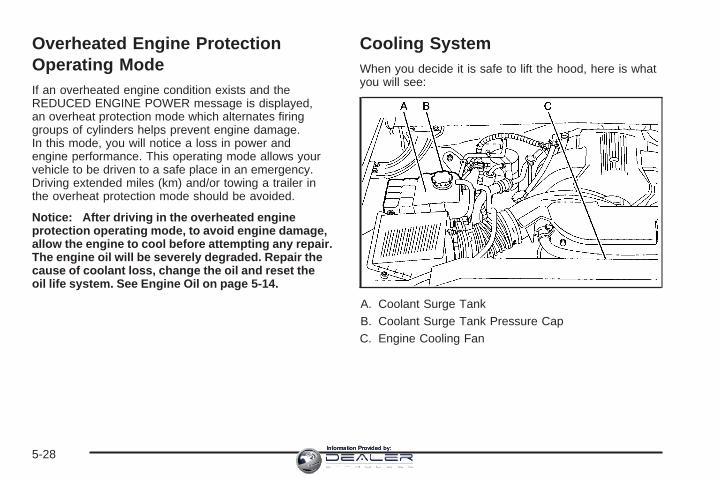
Overheated Engine ProtectionOperating ModeIf an overheated engine condition exists and theREDUCED ENGINE POWER message is displayed,an overheat protection mode which alternates firinggroups of cylinders helps prevent engine damage.In this mode, you will notice a loss in power andengine performance. This operating mode allows yourvehicle to be driven to a safe place in an emergency.Driving extended miles (km) and/or towing a trailer inthe overheat protection mode should be avoided.
Notice: After driving in the overheated engineprotection operating mode, to avoid engine damage,allow the engine to cool before attempting any repair.The engine oil will be severely degraded. Repair thecause of coolant loss, change the oil and reset theoil life system. See Engine Oil on page 5-14.
Cooling SystemWhen you decide it is safe to lift the hood, here is whatyou will see:
A. Coolant Surge TankB. Coolant Surge Tank Pressure CapC. Engine Cooling Fan
5-28Information Provided by:

{CAUTION:
An electric engine cooling fan under the hoodcan start up even when the engine is notrunning and can injure you. Keep hands,clothing and tools away from any underhoodelectric fan.
If the coolant inside the coolant surge tank is boiling,do not do anything else until it cools down. The vehicleshould be parked on a level surface. Check thecoolant level after the system cools down. Some amountof coolant may be lost due to overheating.
The coolant level shouldbe at or above the FULLCOLD mark. If it is not,you may have a leak at thepressure cap or in theradiator hoses, heaterhoses, radiator, waterpump or somewhere elsein the cooling system.
{CAUTION:
Heater and radiator hoses, and other engineparts, can be very hot. Do not touch them.If you do, you can be burned.
Do not run the engine if there is a leak. If yourun the engine, it could lose all coolant. Thatcould cause an engine fire, and you could beburned. Get any leak fixed before you drive thevehicle.
5-29Information Provided by:

If your vehicle is equipped with an electric enginecooling fan, check the coolant temperature gage. If thecoolant temperature is approximately 232°F (111°C),the electric cooling fan should be running. If it isnot, your vehicle needs service. Turn off the engine.
If your vehicle is equipped with an engine-driven coolingfan, start the engine again and see if the fan speedincreases when idle speed is doubled by pushing theaccelerator pedal down. If it does not, your vehicleneeds service. Turn off the engine.
Notice: Engine damage from running your enginewithout coolant is not covered by your warranty.See Overheated Engine Protection Operating Modeon page 5-28 for information on driving to a safeplace in an emergency.
Notice: Using coolant other than DEX-COOL ® maycause premature engine, heater core or radiatorcorrosion. In addition, the engine coolant mayrequire changing sooner, at 30,000 miles (50 000 km)or 24 months, whichever occurs first. Any repairswould not be covered by your warranty. Always useDEX-COOL® (silicate-free) coolant in your vehicle.
How to Add Coolant to the CoolantSurge TankIf you have not found a problem yet, check to see ifcoolant is visible in the surge tank. If coolant is visiblebut the coolant level is not at or above the FULL COLDmark, add a 50/50 mixture of clean, drinkable waterand DEX-COOL® coolant at the coolant surge tank,but be sure the cooling system, including the coolantsurge tank pressure cap, is cool before you do it.See Engine Coolant on page 5-24 for more information.
If no coolant is visible in the surge tank, add coolantas follows:
{CAUTION:
Steam and scalding liquids from a hot coolingsystem can blow out and burn you badly. Theyare under pressure, and if you turn the radiatorpressure cap — even a little — they can comeout at high speed. Never turn the cap when thecooling system, including the radiator pressurecap, is hot. Wait for the cooling system andradiator pressure cap to cool if you ever haveto turn the pressure cap.
5-30Information Provided by:
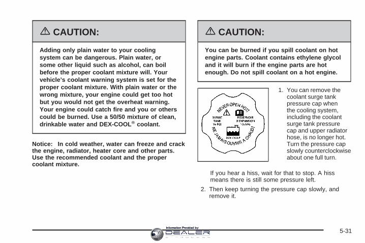
{CAUTION:
Adding only plain water to your coolingsystem can be dangerous. Plain water, orsome other liquid such as alcohol, can boilbefore the proper coolant mixture will. Yourvehicle’s coolant warning system is set for theproper coolant mixture. With plain water or thewrong mixture, your engine could get too hotbut you would not get the overheat warning.Your engine could catch fire and you or otherscould be burned. Use a 50/50 mixture of clean,drinkable water and DEX-COOL ® coolant.
Notice: In cold weather, water can freeze and crackthe engine, radiator, heater core and other parts.Use the recommended coolant and the propercoolant mixture.
{CAUTION:
You can be burned if you spill coolant on hotengine parts. Coolant contains ethylene glycoland it will burn if the engine parts are hotenough. Do not spill coolant on a hot engine.
1. You can remove thecoolant surge tankpressure cap whenthe cooling system,including the coolantsurge tank pressurecap and upper radiatorhose, is no longer hot.Turn the pressure capslowly counterclockwiseabout one full turn.
If you hear a hiss, wait for that to stop. A hissmeans there is still some pressure left.
2. Then keep turning the pressure cap slowly, andremove it.
5-31Information Provided by:

3. Fill the coolant surge tank with the proper mixture,to the FULL COLD mark.
4. With the coolant surge tank pressure cap off, startthe engine and let it run until you can feel the upperradiator hose getting hot. Watch out for theengine cooling fan.By this time, the coolant level inside the coolantsurge tank may be lower. If the level is lower, addmore of the proper mixture to the coolant surge tankuntil the level reaches the FULL COLD mark.
5. Then replace the pressure cap. Be sure thepressure cap is hand-tight and fully seated.
5-32Information Provided by:

Engine Fan NoiseIf your vehicle is equipped with a clutched enginecooling fan, when the clutch is engaged, the fan spinsfaster to provide more air to cool the engine. In mosteveryday driving conditions, the fan is spinning slowerand the clutch is not fully engaged. This improvesfuel economy and reduces fan noise. Under heavyvehicle loading, trailer towing, and/or high outsidetemperatures, the fan speed increases as the clutchmore fully engages, so you may hear an increasein fan noise. This is normal and should not bemistaken as the transmission slipping or making extrashifts. It is merely the cooling system functioningproperly. The fan will slow down when additional coolingis not required and the clutch disengages.
You may also hear this fan noise when you start theengine. It will go away as the fan clutch partiallydisengages.
If your vehicle is equipped with electric cooling fans,you may hear the fans spinning at low speed duringmost everyday driving. The fans may turn off if nocooling is required. Under heavy vehicle loading,trailer towing, and/or high outside temperatures, or ifyou are operating your air conditioning system, the fanschange to high speed and you may hear an increasein fan noise. This is normal and indicates that thecooling system is functioning properly. The fans willchange to low speed when additional cooling isno longer required.
5-33Information Provided by:

Power Steering FluidSee Engine CompartmentOverview on page 5-12for reservoir location.
When to Check Power Steering FluidIt is not necessary to regularly check power steering fluidunless you suspect there is a leak in the system oryou hear an unusual noise. A fluid loss in this systemcould indicate a problem. Have the system inspectedand repaired.
How to Check Power Steering FluidTo check the power steering fluid, do the following:
1. Turn the key off and let the engine compartmentcool down.
2. Wipe the cap and the top of the reservoir clean.
3. Unscrew the cap and wipe the dipstick with aclean rag.
4. Replace the cap and completely tighten it.
5. Remove the cap again and look at the fluid levelon the dipstick.
The level should be at the FULL COLD mark.If necessary, add only enough fluid to bring thelevel up to the mark.
What to UseTo determine what kind of fluid to use, seeRecommended Fluids and Lubricants on page 6-12.Always use the proper fluid. Failure to use the properfluid can cause leaks and damage hoses and seals.
5-34Information Provided by:

Windshield Washer Fluid
What to UseWhen you need windshield washer fluid, be sure to readthe manufacturer’s instructions before use. If you willbe operating your vehicle in an area where thetemperature may fall below freezing, use a fluid that hassufficient protection against freezing.
Adding Washer FluidYour vehicle has a message that comes on when thewasher fluid is low. The message is displayed for15 seconds at the start of each ignition cycle. When theCHECK WASHER FLUID message is displayed, youwill need to add washer fluid to the windshield washerfluid reservoir. See DIC Warnings and Messageson page 3-48 for more information.
Open the cap with thewasher symbol on it.Add washer fluid until thetank is full. See EngineCompartment Overview onpage 5-12 for reservoirlocation.
Notice:
• When using concentrated washer fluid, follow themanufacturer’s instructions for adding water.
• Do not mix water with ready-to-use washer fluid.Water can cause the solution to freeze anddamage your washer fluid tank and other parts ofthe washer system. Also, water does not clean aswell as washer fluid.
• Fill your washer fluid tank only three-quarters fullwhen it is very cold. This allows for expansion iffreezing occurs, which could damage the tank ifit is completely full.
• Do not use engine coolant (antifreeze) in yourwindshield washer. It can damage your washersystem and paint.
5-35Information Provided by:

Brakes
Brake FluidYour brake master cylinderreservoir is filled withDOT-3 brake fluid.See Engine CompartmentOverview on page 5-12for the location of thereservoir.
There are only two reasons why the brake fluid level inthe reservoir might go down. The first is that thebrake fluid goes down to an acceptable level duringnormal brake lining wear. When new linings are put in,the fluid level goes back up. The other reason isthat fluid is leaking out of the brake system. If it is,you should have your brake system fixed, since a leakmeans that sooner or later your brakes will not workwell, or will not work at all.
So, it is not a good idea to top off your brake fluid.Adding brake fluid will not correct a leak. If you add fluidwhen your linings are worn, then you will have toomuch fluid when you get new brake linings. You shouldadd or remove brake fluid, as necessary, only whenwork is done on the brake hydraulic system.
{CAUTION:
If you have too much brake fluid, it can spill onthe engine. The fluid will burn if the engine ishot enough. You or others could be burned,and your vehicle could be damaged. Add brakefluid only when work is done on the brakehydraulic system. See “Checking Brake Fluid”in this section.
Refer to the Maintenance Schedule to determine whento check your brake fluid. See Scheduled Maintenanceon page 6-4.
5-36Information Provided by:

Checking Brake FluidYou can check the brake fluid without taking off the cap.
Look at the brake fluidreservoir. The fluid levelshould be above MIN.If it is not, have your brakesystem checked to seeif there is a leak.
After work is done on the brake hydraulic system,make sure the level is above the MIN but not over theMAX mark.
What to AddWhen you do need brake fluid, use only DOT-3 brakefluid. Use new brake fluid from a sealed containeronly. See Recommended Fluids and Lubricants onpage 6-12.
Always clean the brake fluid reservoir cap and the areaaround the cap before removing it. This will helpkeep dirt from entering the reservoir.
{CAUTION:
With the wrong kind of fluid in your brakesystem, your brakes may not work well, or theymay not even work at all. This could cause acrash. Always use the proper brake fluid.
Notice:
• Using the wrong fluid can badly damage brakesystem parts. For example, just a few drops ofmineral-based oil, such as engine oil, in yourbrake system can damage brake system parts sobadly that they will have to be replaced. Do notlet someone put in the wrong kind of fluid.
• If you spill brake fluid on your vehicle’s paintedsurfaces, the paint finish can be damaged.Be careful not to spill brake fluid on yourvehicle. If you do, wash it off immediately.See Washing Your Vehicle on page 5-103.
5-37Information Provided by:

Brake WearYour vehicle has four-wheel disc brakes.
Disc brake pads have built-in wear indicators that makea high-pitched warning sound when the brake padsare worn and new pads are needed. The soundmay come and go or be heard all the time your vehicleis moving, except when you are pushing on thebrake pedal firmly.
{CAUTION:
The brake wear warning sound means thatsoon your brakes will not work well. Thatcould lead to an accident. When you hear thebrake wear warning sound, have your vehicleserviced.
Notice: Continuing to drive with worn-out brakepads could result in costly brake repair.
Some driving conditions or climates may cause a brakesqueal when the brakes are first applied or lightlyapplied. This does not mean something is wrong withyour brakes.
Properly torqued wheel nuts are necessary to helpprevent brake pulsation. When tires are rotated, inspectbrake pads for wear and evenly tighten wheel nuts inthe proper sequence to GM torque specifications.
Brake linings should always be replaced as completeaxle sets.
Brake Pedal TravelSee your dealer if the brake pedal does not return tonormal height, or if there is a rapid increase inpedal travel. This could be a sign of brake trouble.
Brake AdjustmentEvery time you make a brake stop, your disc brakesadjust for wear.
5-38Information Provided by:

Replacing Brake System PartsThe braking system on a vehicle is complex. Its manyparts have to be of top quality and work well together ifthe vehicle is to have really good braking. Your vehiclewas designed and tested with top-quality GM brakeparts. When you replace parts of your brakingsystem — for example, when your brake linings weardown and you need new ones put in — be sure you getnew approved GM replacement parts. If you do not,your brakes may no longer work properly. For example,if someone puts in brake linings that are wrong foryour vehicle, the balance between your front and rearbrakes can change — for the worse. The brakingperformance you have come to expect can change inmany other ways if someone puts in the wrongreplacement brake parts.
BatteryYour vehicle has a maintenance free battery.When it is time for a new battery, get one that hasthe replacement number shown on the original battery’slabel. We recommend an ACDelco® replacementbattery. See Engine Compartment Overview onpage 5-12 for battery location.
Warning: Battery posts, terminals, and relatedaccessories contain lead and lead compounds,chemicals known to the State of California to causecancer and reproductive harm. Wash hands afterhandling.
Vehicle StorageIf you are not going to drive your vehicle for 25 daysor more, remove the black, negative (−) cable fromthe battery. This will help keep your battery fromrunning down.
{CAUTION:
Batteries have acid that can burn you and gasthat can explode. You can be badly hurt ifyou are not careful. See Jump Starting onpage 5-40 for tips on working around a batterywithout getting hurt.
To reprogram your sunroof (if equipped), see Sunroofon page 2-73.
5-39Information Provided by:

Jump StartingIf your vehicle’s battery has run down, you may want touse another vehicle and some jumper cables to startyour vehicle. Be sure to use the following steps todo it safely.
{CAUTION:
Batteries can hurt you. They can be dangerousbecause:
• They contain acid that can burn you.• They contain gas that can explode or
ignite.• They contain enough electricity to burn
you.
If you do not follow these steps exactly, someor all of these things can hurt you.
Notice: Ignoring these steps could result in costlydamage to your vehicle that would not be coveredby your warranty.
Trying to start your vehicle by pushing or pulling itwill not work, and it could damage your vehicle.
1. Check the other vehicle. It must have a 12-voltbattery with a negative ground system.
Notice: If the other vehicle’s system is not a 12-voltsystem with a negative ground, both vehicles canbe damaged. Only use vehicles with 12-volt systemswith negative grounds to jump start your vehicle.
2. Get the vehicles close enough so the jumper cablescan reach, but be sure the vehicles are not touchingeach other. If they are, it could cause a groundconnection you do not want. You would not be ableto start your vehicle, and the bad groundingcould damage the electrical systems.To avoid the possibility of the vehicles rolling, setthe parking brake firmly on both vehicles involved inthe jump start procedure. Put an automatictransmission in PARK (P) or a manual transmissionin NEUTRAL before setting the parking brake.
5-40Information Provided by:

Notice: If you leave your radio or other accessorieson during the jump starting procedure, they couldbe damaged. The repairs would not be coveredby your warranty. Always turn off your radio andother accessories when jump starting your vehicle.
3. Turn off the ignition on both vehicles. Unplugunnecessary accessories plugged into the cigarettelighter or accessory power outlets. Turn off theradio and all lamps that are not needed. This willavoid sparks and help save both batteries.And it could save your radio!
4. Open the hoods and locate the positive (+) andnegative (−) terminal locations of the other vehicle.Your vehicle has a remote positive (+) jump startingterminal and a remote negative (−) jump startingterminal. You should always use these remoteterminals instead of the terminals on the battery.
The remote positive (+)terminal is located near theengine accessory drivebracket. On some vehicles,the terminal may becovered by a red plasticcover. To access theremote positive (+)terminal, open the cover,if equipped.
The remote negative (−)terminal is located on theengine accessory drivebracket and is markedGND (Ground).
See Engine Compartment Overview on page 5-12for more information on the location of theremote terminals.
5-41Information Provided by:

{CAUTION:
Using a match near a battery can cause batterygas to explode. People have been hurt doingthis, and some have been blinded. Use aflashlight if you need more light.
Be sure the battery has enough water. You donot need to add water to the battery installedin your new vehicle. But if a battery has fillercaps, be sure the right amount of fluid is there.If it is low, add water to take care of that first.If you do not, explosive gas could be present.
Battery fluid contains acid that can burn you.Do not get it on you. If you accidentally get itin your eyes or on your skin, flush the placewith water and get medical help immediately.
5. Check that the jumper cables do not have loose ormissing insulation. If they do, you could get ashock. The vehicles could be damaged too.Before you connect the cables, here are somebasic things you should know. Positive (+) will go topositive (+) or to a remote positive terminal (+) ifthe vehicle has one. Negative (−) will go to a heavy,unpainted metal engine part or to a remotenegative (−) terminal, if the vehicle has one.Do not connect positive (+) to negative (−) or youwill get a short that would damage the batteryand maybe other parts too.
{CAUTION:
Fans or other moving engine parts can injureyou badly. Keep your hands away from movingparts once the engine is running.
5-42Information Provided by:

6. Connect the red positive (+) cable to the positive (+)terminal of the dead battery. Use a remotepositive (+) terminal if the vehicle has one.
7. Do not let the other end touch metal. Connect it tothe positive (+) terminal of the good battery. Use aremote positive (+) terminal if the vehicle has one.
8. Now connect the black negative (−) cable to thenegative (−) terminal of the good battery. Use aremote negative (−) terminal if the vehicle has one.Do not let the other end touch anything until thenext step. The other end of the negative (−) cabledoes not go to the dead battery. It goes to aheavy, unpainted metal engine part or to a remotenegative (−) terminal on the vehicle with thedead battery.
9. Connect the other end of the negative (−) cable atleast 18 inches (45 cm) away from the dead battery,but not near engine parts that move. The electricalconnection is just as good there, and the chanceof sparks getting back to the battery is much less.Use a remote negative (−) terminal if the vehicle hasone. Your vehicle’s remote negative (−) terminalis marked GND.
10. Now start the vehicle with the good battery and runthe engine for awhile.
11. Try to start the vehicle that had the dead battery.If it will not start after a few tries, it probablyneeds service.
5-43Information Provided by:
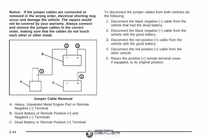
Notice: If the jumper cables are connected orremoved in the wrong order, electrical shorting mayoccur and damage the vehicle. The repairs wouldnot be covered by your warranty. Always connectand remove the jumper cables in the correctorder, making sure that the cables do not toucheach other or other metal.
A. Heavy, Unpainted Metal Engine Part or RemoteNegative (−) Terminal
B. Good Battery or Remote Positive (+) andNegative (−) Terminals
C. Dead Battery or Remote Positive (+) Terminal
To disconnect the jumper cables from both vehicles dothe following:
1. Disconnect the black negative (−) cable from thevehicle that had the dead battery.
2. Disconnect the black negative (−) cable from thevehicle with the good battery.
3. Disconnect the red positive (+) cable from thevehicle with the good battery.
4. Disconnect the red positive (+) cable from theother vehicle.
5. Return the positive (+) remote terminal cover,if equipped, to its original position.
Jumper Cable Removal
5-44Information Provided by:

All-Wheel DriveTransfer CaseBe sure to perform the lubricant checks described inthis section. There are two additional systems thatneed lubrication.
When to Check LubricantRefer to the Maintenance Schedule to determinehow often to check the lubricant. See ScheduledMaintenance on page 6-4.
How to Check Lubricant
To get an accurate reading, the vehicle should be on alevel surface.If the level is below the bottom of the filler plug hole,located on the transfer case, you’ll need to addsome lubricant. Add enough lubricant to raise the levelto the bottom of the filler plug hole. Use care not toovertighten the plug.
What to UseRefer to the Maintenance Schedule to determine whatkind of lubricant to use. See Recommended Fluidsand Lubricants on page 6-12.
(A) Drain Plug (B) Filler Plug
5-45Information Provided by:

Rear AxleWhen to Check LubricantIt is not necessary to regularly check rear axle fluidunless you suspect there is a leak or you hear anunusual noise. A fluid loss could indicate a problem.Have it inspected and repaired.
All axle assemblies are filled by volume of fluid duringproduction. They are not filled to reach a certainlevel. When checking the fluid level on any axle,variations in the readings can be caused by factory filldifferences between the minimum and the maximumfluid volume. Also, if a vehicle has just been drivenbefore checking the fluid level, it may appear lower thannormal because fluid has traveled out along the axletubes and has not drained back to the sump area.Therefore, a reading taken five minutes after the vehiclehas been driven will appear to have a lower fluidlevel than a vehicle that has been stationary for anhour or two. Remember that the rear axle assemblymust be supported to get a true reading.
How to Check Lubricant
To get an accurate reading, the vehicle should be on alevel surface.
The proper level is from 5/8 inch to 1-5/8 inch (15 mm to40 mm) below the bottom of the filler plug hole,located on the rear axle. Add only enough fluid to reachthe proper level.
What to UseRefer to the Maintenance Schedule to determine whatkind of lubricant to use. See Recommended Fluidsand Lubricants on page 6-12.
5-46Information Provided by:
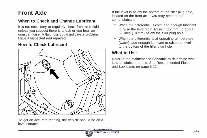
Front AxleWhen to Check and Change LubricantIt is not necessary to regularly check front axle fluidunless you suspect there is a leak or you hear anunusual noise. A fluid loss could indicate a problem.Have it inspected and repaired.
How to Check Lubricant
To get an accurate reading, the vehicle should be on alevel surface.
If the level is below the bottom of the filler plug hole,located on the front axle, you may need to addsome lubricant:
• When the differential is cold, add enough lubricantto raise the level from 1/2 inch (12 mm) to about5/8 inch (18 mm) below the filler plug hole.
• When the differential is at operating temperature(warm), add enough lubricant to raise the levelto the bottom of the filler plug hole.
What to UseRefer to the Maintenance Schedule to determine whatkind of lubricant to use. See Recommended Fluidsand Lubricants on page 6-12.
5-47Information Provided by:
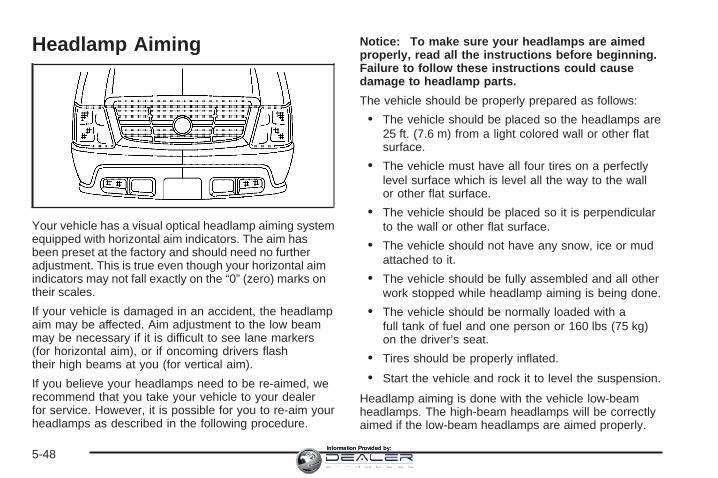
Headlamp Aiming
Your vehicle has a visual optical headlamp aiming systemequipped with horizontal aim indicators. The aim hasbeen preset at the factory and should need no furtheradjustment. This is true even though your horizontal aimindicators may not fall exactly on the “0” (zero) marks ontheir scales.
If your vehicle is damaged in an accident, the headlampaim may be affected. Aim adjustment to the low beammay be necessary if it is difficult to see lane markers(for horizontal aim), or if oncoming drivers flashtheir high beams at you (for vertical aim).
If you believe your headlamps need to be re-aimed, werecommend that you take your vehicle to your dealerfor service. However, it is possible for you to re-aim yourheadlamps as described in the following procedure.
Notice: To make sure your headlamps are aimedproperly, read all the instructions before beginning.Failure to follow these instructions could causedamage to headlamp parts.
The vehicle should be properly prepared as follows:
• The vehicle should be placed so the headlamps are25 ft. (7.6 m) from a light colored wall or other flatsurface.
• The vehicle must have all four tires on a perfectlylevel surface which is level all the way to the wallor other flat surface.
• The vehicle should be placed so it is perpendicularto the wall or other flat surface.
• The vehicle should not have any snow, ice or mudattached to it.
• The vehicle should be fully assembled and all otherwork stopped while headlamp aiming is being done.
• The vehicle should be normally loaded with afull tank of fuel and one person or 160 lbs (75 kg)on the driver’s seat.
• Tires should be properly inflated.
• Start the vehicle and rock it to level the suspension.
Headlamp aiming is done with the vehicle low-beamheadlamps. The high-beam headlamps will be correctlyaimed if the low-beam headlamps are aimed properly.
5-48Information Provided by:

The headlamp aiming devices are under the hood nearthe headlamps.
If you believe your headlamps need horizontal (H)(left/right) adjustment, follow the horizontal aimingprocedure. If you believe your headlamps need onlyvertical (V) (up/down) adjustment, follow only the verticalaiming procedure.
Adjustment screws can be turned with an E8 Torx®
socket or T15 Torx® screwdriver.
Headlamp Horizontal AimingTurn the horizontal aiming screw (A) until theindicator (B) is lined up with zero.
Once the horizontal aim is adjusted, then adjust thevertical aim.
5-49Information Provided by:

Headlamp Vertical AimingNotice: Horizontal aiming must be performedbefore making any adjustments to the vertical aim.Adjusting the vertical aim first will result in anincorrect headlamp aim.
1. Find the aim dot on the lens of the low-beamheadlamps.
2. Measure the distance from the ground to the aimdot on each low-beam headlamp. Record thisdistance.
3. At the wall or other flat surface, measure from theground upward the recorded distance from Step 2and draw or tape a horizontal line the width ofthe vehicle.
Notice: Do not cover a headlamp to improve beamcut-off when aiming. Covering a headlamp maycause excessive heat build-up which may causedamage to the headlamp.
5-50Information Provided by:
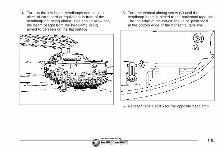
4. Turn on the low-beam headlamps and place apiece of cardboard or equivalent in front of theheadlamp not being aimed. This should allow onlythe beam of light from the headlamp beingaimed to be seen on the flat surface.
5. Turn the vertical aiming screw (V) until theheadlamp beam is aimed to the horizontal tape line.The top edge of the cut-off should be positionedat the bottom edge of the horizontal tape line.
6. Repeat Steps 4 and 5 for the opposite headlamp.
5-51Information Provided by:
Bulb ReplacementFor the proper type of replacement bulbs, seeReplacement Bulbs on page 5-58.
For any bulb changing procedure not listed in thissection, contact your dealer.
High Intensity Discharge (HID)Lighting
{CAUTION:
The low beam high intensity discharge lightingsystem operates at a very high voltage. If youtry to service any of the system components,you could be seriously injured. Have yourdealer or a qualified technician service them.
Your vehicle has HID low-beam headlamps. After yourvehicle’s HID headlamp bulb has been replaced,you may notice that the beam is a slightly differentshade than it was originally. This is normal.
Halogen Bulbs
{CAUTION:
Halogen bulbs have pressurized gas insideand can burst if you drop or scratch the bulb.You or others could be injured. Be sure toread and follow the instructions on the bulbpackage.
5-52Information Provided by:

Headlamps
A. Low-Beam HeadlampB. Daytime Running
Lamp (DRL)C. Sidemarker Lamp
D. High-BeamHeadlamp
E. Front Parking/TurnSignal Lamp
To replace a headlamp bulb, do the following:
1. Open the hood of the vehicle. See Hood Releaseon page 5-11 for more information.
2. Pry up the eight fastener plugs on the radiatorcover and pull the fasteners out.
3. Lift off the radiator cover.
5-53Information Provided by:

4. Pull the top left or right corner of the grill out so theclips release. This will give you the neededclearance for removing the headlamp assembly.
5. Remove the horizontal pin from the headlampassembly by lifting the end of the pin upwarduntil it unsnaps and then pulling it toward the centerof the vehicle.
5-54Information Provided by:

6. Remove the vertical pin from the headlampassembly by turning the end of the pin away fromyou until it unsnaps and then pulling it upward.
7. Remove the headlamp assembly by lifting it up andthen pulling it out and away from the front of thevehicle.
8. Disconnect the electrical connector from the lowercorner of the headlamp assembly. This will give youbetter access to the headlamp assembly.
9. Remove the rubber,circular-shaped bulbcap of the affected bulbfrom the headlampassembly.
10. Turn the bulb connector counterclockwise andremove it with the old bulb from the headlampassembly.
11. Unplug the electrical connector from the old bulb.
12. Plug in the electrical connector to the new bulb,using care not to touch the bulb with your hands,fingers or anything damp or oily.
5-55Information Provided by:

13. Place the headlamp assembly back into the vehicle,being sure to align the lower locator tab with thepocket on the vehicle (see arrow). Push theheadlamp assembly straight in and then down intoposition.
14. Install the two pins and snap the ends into theirlocked position.
15. Reinstall the grille and radiator cover by reversingthe removal procedure described previously.
Front Turn Signal, Sidemarker andDaytime Running Lamps
A. Low-Beam HeadlampB. Daytime Running
Lamp (DRL)C. Sidemarker Lamp
D. High-BeamHeadlamp
E. Front Parking/TurnSignal Lamp
5-56Information Provided by:

To replace a front turn signal, sidemarker or DRL bulb,do the following:
1. Remove the headlamp assembly as describedpreviously. See Headlamps on page 5-53 formore information.
2. Remove the rubber, circular-shaped bulb cap forthe affected bulb from the headlamp assembly.
3. Press the locking release lever, turn the bulbsocket counterclockwise and remove it from theheadlamp assembly. (There is no lock for thesidemarker lamp.)
4. Remove the old bulb from the bulb socket.
5. Put the new bulb into the bulb socket.
6. Put the bulb socket into the turn signal housingand turn it clockwise until it locks. (There is nolock for the sidemarker lamp.)
7. Reverse the steps to reinstall.
Taillamps, Turn Signal, Stoplampsand Back-up LampsTo replace one of these bulbs, do the following:
A. Stoplamp/TaillampB. Turn Signal
Lamp/TaillampC. Back-up Lamp
1. Open the tailgate. See Tailgate on page 2-19for more information.
5-57Information Provided by:
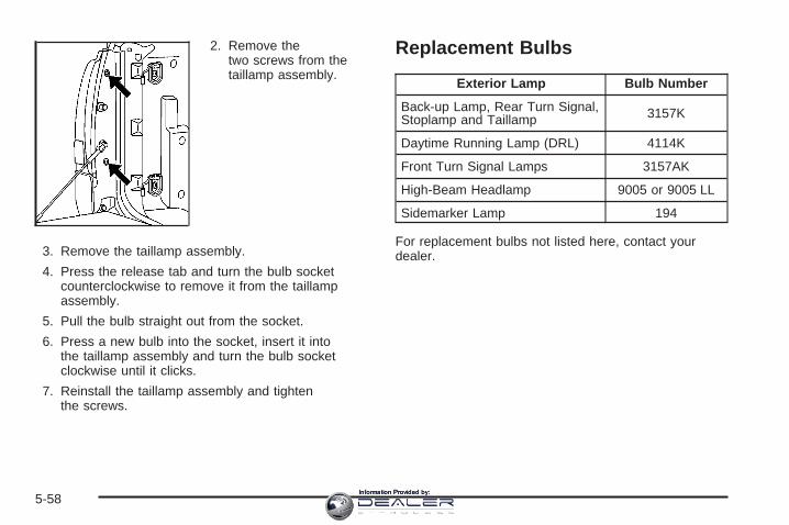
2. Remove thetwo screws from thetaillamp assembly.
3. Remove the taillamp assembly.
4. Press the release tab and turn the bulb socketcounterclockwise to remove it from the taillampassembly.
5. Pull the bulb straight out from the socket.
6. Press a new bulb into the socket, insert it intothe taillamp assembly and turn the bulb socketclockwise until it clicks.
7. Reinstall the taillamp assembly and tightenthe screws.
Replacement Bulbs
Exterior Lamp Bulb Number
Back-up Lamp, Rear Turn Signal,Stoplamp and Taillamp 3157K
Daytime Running Lamp (DRL) 4114K
Front Turn Signal Lamps 3157AK
High-Beam Headlamp 9005 or 9005 LL
Sidemarker Lamp 194
For replacement bulbs not listed here, contact yourdealer.
5-58Information Provided by:

Windshield Wiper BladeReplacementWindshield wiper blades should be inspected for wearand cracking. See Scheduled Maintenance on page 6-4for more information.
Replacement blades come in different types and areremoved in different ways. For proper type and length,see Normal Maintenance Replacement Parts onpage 6-14.
To replace the windshield wiper blade assemblydo the following:
1. Lift the wiper arm away from the windshield.
2. Push the release lever (B) to disengage the hookand push the wiper arm (A) out of the blade (C).
3. Push the new wiper blade securely on the wiperarm until you hear the release lever click intoplace.
5-59Information Provided by:

TiresYour new vehicle comes with high-quality tires made bya leading tire manufacturer. If you ever have questionsabout your tire warranty and where to obtain service,see your GM Warranty booklet for details. For additionalinformation refer to the tire manufacturer’s bookletincluded with your vehicle’s Owner Manual.
{CAUTION:
Poorly maintained and improperly used tiresare dangerous.
• Overloading your tires can causeoverheating as a result of too muchfriction. You could have an air-out and aserious accident. See Loading YourVehicle on page 4-44.
CAUTION: (Continued)
CAUTION: (Continued)
• Underinflated tires pose the same dangeras overloaded tires. The resulting accidentcould cause serious injury. Check all tiresfrequently to maintain the recommendedpressure. Tire pressure should be checkedwhen your tires are cold. See Inflation - TirePressure on page 5-66.
• Overinflated tires are more likely to becut, punctured, or broken by a suddenimpact — such as when you hit a pothole.Keep tires at the recommended pressure.
• Worn, old tires can cause accidents. If yourtread is badly worn, or if your tires havebeen damaged, replace them.
5-60Information Provided by:
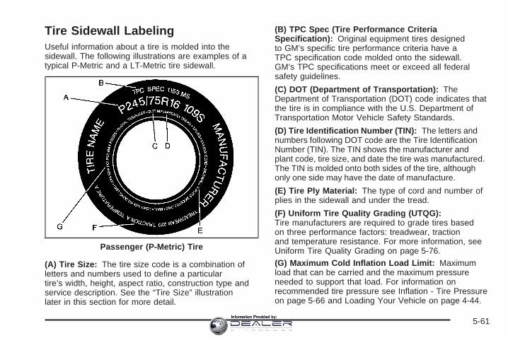
Tire Sidewall LabelingUseful information about a tire is molded into thesidewall. The following illustrations are examples of atypical P-Metric and a LT-Metric tire sidewall.
(A) Tire Size: The tire size code is a combination ofletters and numbers used to define a particulartire’s width, height, aspect ratio, construction type andservice description. See the “Tire Size” illustrationlater in this section for more detail.
(B) TPC Spec (Tire Performance CriteriaSpecification): Original equipment tires designedto GM’s specific tire performance criteria have aTPC specification code molded onto the sidewall.GM’s TPC specifications meet or exceed all federalsafety guidelines.
(C) DOT (Department of Transportation): TheDepartment of Transportation (DOT) code indicates thatthe tire is in compliance with the U.S. Department ofTransportation Motor Vehicle Safety Standards.
(D) Tire Identification Number (TIN): The letters andnumbers following DOT code are the Tire IdentificationNumber (TIN). The TIN shows the manufacturer andplant code, tire size, and date the tire was manufactured.The TIN is molded onto both sides of the tire, althoughonly one side may have the date of manufacture.
(E) Tire Ply Material: The type of cord and number ofplies in the sidewall and under the tread.
(F) Uniform Tire Quality Grading (UTQG):Tire manufacturers are required to grade tires basedon three performance factors: treadwear, tractionand temperature resistance. For more information, seeUniform Tire Quality Grading on page 5-76.(G) Maximum Cold Inflation Load Limit: Maximumload that can be carried and the maximum pressureneeded to support that load. For information onrecommended tire pressure see Inflation - Tire Pressureon page 5-66 and Loading Your Vehicle on page 4-44.
Passenger (P-Metric) Tire
5-61Information Provided by:

(A) Tire Size: The tire size code is a combination ofletters and numbers used to define a particulartire’s width, height, aspect ratio, construction type andservice description. See the “Tire Size” illustrationlater in this section for more detail.
(B) TPC Spec (Tire Performance CriteriaSpecification): Original equipment tires designedto GM’s specific tire performance criteria have aTPC specification code molded onto the sidewall.
GM’s TPC specifications meet or exceed all federalsafety guidelines.
(C) Dual Tire Maximum Load: Maximum load thatcan be carried and the maximum pressure needed tosupport that load when used in a dual configuration.For information on recommended tire pressure seeInflation - Tire Pressure on page 5-66 and Loading YourVehicle on page 4-44.
(D) DOT (Department of Transportation): TheDepartment of Transportation (DOT) code indicates thatthe tire is in compliance with the U.S. Department ofTransportation Motor Vehicle Safety Standards.
(E) Tire Identification Number (TIN): The letters andnumbers following DOT code are the Tire IdentificationNumber (TIN). The TIN shows the manufacturer andplant code, tire size, and date the tire was manufactured.The TIN is molded onto both sides of the tire, althoughonly one side may have the date of manufacture.
(F) Tire Ply Material: The type of cord and number ofplies in the sidewall and under the tread.
(G) Single Tire Maximum Load: Maximum load thatcan be carried and the maximum pressure needed tosupport that load when used as a single. For informationon recommended tire pressure see Inflation - TirePressure on page 5-66 and Loading Your Vehicle onpage 4-44.
Light Truck (LT-Metric) Tire
5-62Information Provided by:

Tire SizeThe following examples show the different parts of a tiresize.
(A) Passenger (P-Metric) Tire: The United Statesversion of a metric tire sizing system. The letter P asthe first character in the tire size means a passengervehicle tire engineered to standards set by the U.S. Tireand Rim Association.
(A) Light Truck (LT-Metric) Tire: The United Statesversion of a metric tire sizing system. The letters LT asthe first two characters in the tire size means a lighttruck tire engineered to standards set by the U.S. Tireand Rim Association.
(B) Tire Width: The three-digit number indicates thetire section width in millimeters from sidewall to sidewall.
(C) Aspect Ratio: A two-digit number that indicatesthe tire height-to-width measurements. For example, ifthe tire size aspect ratio is 75, as shown in item C of thelight truck (LT-Metric) tire illustration, it would meanthat the tire’s sidewall is 75% as high as it is wide.
(D) Construction Code: A letter code is used toindicate the type of ply construction in the tire.The letter R means radial ply construction;the letter D means diagonal or bias ply construction;and the letter B means belted-bias ply construction.
(E) Rim Diameter: Diameter of the wheel in inches.
(F) Service Description: The service descriptionindicates the load range and speed rating of a tire.The load index can range from 1 to 279. Speed ratingsrange from A to Z.
Passenger (P-Metric) Tire
Light Truck (LT-Metric) Tire
5-63Information Provided by:
Tire Terminology and DefinitionsAir Pressure: The amount of air inside the tire pressingoutward on each square inch of the tire. Air pressureis expressed in pounds per square inch (psi) orkilopascal (kPa).
Accessory Weight: This means the combined weightof optional accessories. Some examples of optionalaccessories are, automatic transmission, power steering,power brakes, power windows, power seats, and airconditioning.
Aspect Ratio: The relationship of a tire’s height toits width.
Belt: A rubber coated layer of cords that is locatedbetween the plies and the tread. Cords may be madefrom steel or other reinforcing materials.
Bead: The tire bead contains steel wires wrapped bysteel cords that hold the tire onto the rim.
Bias Ply Tire: A pneumatic tire in which the plies arelaid at alternate angles less than 90 degrees to thecenterline of the tread.
Cold Inflation Pressure: The amount of air pressurein a tire, measured in pounds per square inch (psi)or kilopascals (kPa) before a tire has built up heat fromdriving. See Inflation - Tire Pressure on page 5-66.
Curb Weight: This means the weight of a motorvehicle with standard and optional equipment includingthe maximum capacity of fuel, oil and coolant, butwithout passengers and cargo.
DOT Markings: A code molded into the sidewall of atire signifying that the tire is in compliance with theU.S. Department of Transportation (DOT) motor vehiclesafety standards. The DOT code includes the TireIdentification Number (TIN), an alphanumeric designatorwhich can also identify the tire manufacturer, productionplant, brand and date of production.
GVWR: Gross Vehicle Weight Rating, see LoadingYour Vehicle on page 4-44.
GAWR FRT: Gross Axle Weight Rating for the frontaxle, see Loading Your Vehicle on page 4-44.
GAWR RR: Gross Axle Weight Rating for the rear axle,see Loading Your Vehicle on page 4-44.
Intended Outboard Sidewall: The side of anasymmetrical tire, that must always face outward whenmounted on a vehicle.
Kilopascal (kPa): The metric unit for air pressure.
Light Truck (LT-Metric) Tire: A tire used on light dutytrucks and some multipurpose passenger vehicles.
5-64Information Provided by:

Load Index: An assigned number ranging from 1 to 279that corresponds to the load carrying capacity of a tire.
Maximum Inflation Pressure: The maximum airpressure to which a cold tire may be inflated.The maximum air pressure is molded onto the sidewall.
Maximum Load Rating: The load rating for a tire atthe maximum permissible inflation pressure for that tire.
Maximum Loaded Vehicle Weight: The sum ofcurb weight; accessory weight; vehicle capacity weight;and production options weight.
Normal Occupant Weight: The number of occupants avehicle is designed to seat multiplied by 150 lbs (68 kg).See Loading Your Vehicle on page 4-44.
Occupant Distribution: Designated seating positions.
Outward Facing Sidewall: The side of anasymmetrical tire that has a particular side that facesoutward when mounted on a vehicle. The side of the tirethat contains a whitewall, bears white lettering, orbears manufacturer, brand, and/or model name moldingthat is higher or deeper than the same moldings onthe other sidewall of the tire.
Passenger (P-Metric) Tire: A tire used on passengercars and some light duty trucks and multipurposevehicles.
Recommended Inflation Pressure: Vehiclemanufacturer’s recommended tire inflation pressure andshown on the tire placard. See Inflation - Tire Pressureon page 5-66 and Loading Your Vehicle on page 4-44.
Radial Ply Tire: A pneumatic tire in which the ply cordsthat extend to the beads are laid at 90 degrees to thecenterline of the tread.
Rim: A metal support for a tire and upon which the tirebeads are seated.
Sidewall: The portion of a tire between the tread andthe bead.
Speed Rating: An alphanumeric code assigned to atire indicating the maximum speed at which a tirecan operate.
Traction: The friction between the tire and the roadsurface. The amount of grip provided.
Tread: The portion of a tire that comes into contactwith the road.
5-65Information Provided by:

Treadwear Indicators: Narrow bands, sometimescalled wear bars, that show across the tread of a tirewhen only 1/16 inch (1.6 mm) of tread remains.See When It Is Time for New Tires on page 5-74.
UTQGS (Uniform Tire Quality Grading Standards):A tire information system that provides consumerswith ratings for a tire’s traction, temperature, andtreadwear. Ratings are determined by tire manufacturersusing government testing procedures. The ratings aremolded into the sidewall of the tire. See UniformTire Quality Grading on page 5-76.
Vehicle Capacity Weight: The number of designatedseating positions multiplied by 150 lbs (68 kg) plusthe rated cargo load. See Loading Your Vehicleon page 4-44.
Vehicle Maximum Load on the Tire: Load on anindividual tire due to curb weight, accessory weight,occupant weight, and cargo weight.
Vehicle Placard: A label permanently attached to avehicle showing the vehicle’s capacity weight andthe original equipment tire size and recommendedinflation pressure. See “Tire and Loading InformationLabel” under Loading Your Vehicle on page 4-44.
Inflation - Tire PressureTires need the correct amount of air pressure to operateeffectively.
Notice: Do not let anyone tell you thatunder-inflation or over-inflation is all right. It is not.If your tires do not have enough air (under-inflation),you can get the following:
• Too much flexing
• Too much heat
• Tire overloading
• Premature or irregular wear
• Poor handling
• Reduced fuel economy
If your tires have too much air (over-inflation),you can get the following:
• Unusual wear
• Poor handling
• Rough ride
• Needless damage from road hazards
5-66Information Provided by:

A Tire and Loading Information label is attached to thevehicle’s center pillar (B-pillar), below the driver’sdoor lock post (striker). This label lists your vehicle’soriginal equipment tires and their recommended coldtire inflation pressures. The recommended cold tireinflation pressure, shown on the label, is the minimumamount of air pressure needed to support your vehicle’smaximum load carrying capacity.
For additional information regarding how much weightyour vehicle can carry, and an example of the tireand loading information label, see Loading Your Vehicleon page 4-44.
When to CheckCheck your tires once a month or more. Do not forgetto check the spare tire. For additional informationregarding the spare tire, see Spare Tire on page 5-99.
How to CheckUse a good quality pocket-type gage to check tirepressure. You cannot tell if your tires are properlyinflated simply by looking at them. Radial tires maylook properly inflated even when they are underinflated.Check the tire’s inflation pressure when the tires arecold. Cold means your vehicle has been sittingfor at least three hours or driven no more than1 mile (1.6 km).
Remove the valve cap from the tire valve stem. Pressthe tire gage firmly onto the valve to get a pressuremeasurement. If the cold tire inflation pressure matchesthe recommended pressure on the Tire and LoadingInformation label, no further adjustment is necessary.If the inflation pressure is low, add air until you reach therecommended amount.
If you overfill the tire, release air by pushing on themetal stem in the center of the tire valve. Recheck thetire pressure with the tire gage.
Be sure to put the valve caps back on the valve stems.They help prevent leaks by keeping out dirt and moisture.
5-67Information Provided by:

High Speed Operation
{CAUTION:
Driving at high speeds, 100 mph (160 km/h) orhigher, puts an additional strain on tires.Sustained high-speed driving causes excessiveheat build up and can cause sudden tire failure.You could have a crash and you or others couldbe killed. Some high-speed rated tires requireinflation pressure adjustment for high speedoperation. When speed limits and roadconditions are such that a vehicle can be drivenat high speeds, make sure the tires are rated forhigh speed operation, in excellent condition,and set to the correct cold tire inflation pressurefor the vehicle load.
If your vehicle has P265/70R17 AL2 size tires and youwill be driving at high speeds, speeds of 100 mph(160 km/h) or higher, set the cold inflation pressure tothe maximum inflation pressure shown on the tiresidewall, or 38 psi (265 kPa), whichever is lower.See the example following. When you end thishigh-speed driving, return the tires to the cold inflationpressure shown on the Tire and Loading Informationlabel. See Loading Your Vehicle on page 4-44.
Example:
You will find the maximum load and inflation pressuremolded on the tire’s sidewall, in small letters, nearthe rim flange. It will read something like this: Maximumload 690 kg (1521 lbs) 300 kPa (44 psi) Max. Press.
For this example, you would set the inflation pressurefor high-speed driving at 38 psi (265 kPa).
5-68Information Provided by:

Tire Pressure Monitor SystemThe Tire Pressure Monitor System (TPMS) uses radioand sensor technology to check tire pressure levels.If your vehicle has this feature, sensors are mounted oneach tire and wheel assembly, except the spare tire.The TPMS sensors monitor the air pressure in yourvehicle’s tires and transmit tire pressure readings to areceiver located in the vehicle.
The TPMS is designed to alert the driver, if a low tirepressure condition exists. This system also allowsthe driver to check tire pressure levels using theDriver Information Center (DIC).
When a low tire pressure condition is detected, the TPMSdisplays the CHECK TIRE PRESSURE warning messageon the DIC, and at the same time illuminates the low tirepressure warning symbol. For additional information anddetails about the DIC operation and displays see DICOperation and Displays on page 3-45 and DIC Warningsand Messages on page 3-48.
You may notice, during cooler weather conditions,that the tire pressure monitor light, located on theinstrument panel cluster, and the CHECK TIREPRESSURE message will appear when the vehicle isfirst started and then turn off as you start to drivethe vehicle. This could be an early indicator that the tirepressures are getting low and need to be inflated tothe proper pressure.
Each tire, including the spare (if provided), should bechecked monthly when cold and inflated to the inflationpressure recommended by the vehicle manufactureron the vehicle placard or tire inflation pressure label.(If your vehicle has tires of a different size than thesize indicated on the vehicle placard or tire inflationpressure label, you should determine the proper inflationpressure for those tires.)
As an added safetyfeature, your vehicle hasbeen equipped with atire pressure monitoringsystem (TPMS) thatilluminates a low tirepressure telltale when oneor more of your tires issignificantly under-inflated.
Accordingly, When the low tire pressure telltaleilluminates, you should stop and check your tires assoon as possible, and inflate them to the properpressure. Driving on a significantly under-inflated tirecauses the tire to overheat and can lead to tire failure.Under-inflation also reduces fuel efficiency and tiretread life, and may affect the vehicle’s handlingand stopping ability.
5-69Information Provided by:

Please note that the TPMS is not a substitute for propertire maintenance, and it is the driver’s responsibility tomaintain correct tire pressure, even if under-inflation hasnot reached the level to trigger illumination of theTPMS low tire pressure telltale.
The CHECK TIRE PRESSURE warning message andlow tire pressure light (telltale) will appear at eachignition cycle until the tires are inflated to the correctinflation pressure.
The Tire and Loading Information label (tire informationplacard) shows the size of your vehicle’s originaltires and the correct inflation pressure for your vehicle’stires when they are cold. See Inflation - Tire Pressureon page 5-66. For the location of the tire and loadinginformation label, see Loading Your Vehicle onpage 4-44.
Your vehicle’s TPMS can alert you about a low tirepressure condition but it does not replace normal tiremaintenance. See Tire Inspection and Rotation onpage 5-72 and Tires on page 5-60.
Notice: Do not use a tire sealant if your vehiclehas Tire Pressure Monitors. The liquid sealant candamage the tire pressure monitor sensors.
Resetting the TPMS Identification CodesEach TPMS sensor has a unique identificationcode. Any time you rotate your vehicle’s tires or replaceone or more of the TPMS sensors, the identificationcodes will need to be matched to the new tire/wheelposition. Each tire/wheel position is matched to asensor, by increasing or decreasing the tire’s airpressure. The sensors are matched to the tire/wheelpositions in the following order: LF TIRE (left front tire onthe driver’s side of the vehicle), RF TIRE (right fronttire on the passengers side of the vehicle), RR TIRE(right rear tire on the passengers side of the vehicle),and LR TIRE (left rear tire on the driver’s side ofthe vehicle).
You will have one minute to match the first tire/wheelposition, and five minutes overall to match all fourtire/wheel positions. If it takes longer than one minute,to match the first tire and wheel, or more than fiveminutes to match all four tire and wheel positions thematching process stops and you will need to start over.
5-70Information Provided by:
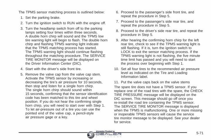
The TPMS sensor matching process is outlined below:
1. Set the parking brake.
2. Turn the ignition switch to RUN with the engine off.
3. Turn the headlamp switch from off to the parkinglamps setting four times within three seconds.A double horn chirp will sound and the TPMS lowtire warning light will begin to flash. The double hornchirp and flashing TPMS warning light indicatethat the TPMS matching process has started.The TPMS warning light should continue flashingthroughout the matching procedure. The SERVICETIRE MONITOR message will be displayed onthe Driver Information Center (DIC).
4. Start with the driver’s side front tire.
5. Remove the valve cap from the valve cap stem.Activate the TPMS sensor by increasing ordecreasing the tire’s air pressure for 10 seconds,then stop and listen for a single horn chirp.The single horn chirp should sound within15 seconds, confirming that the sensor identificationcode has been matched to this tire and wheelposition. If you do not hear the confirming singlehorn chirp, you will need to start over with Step 1.To let air-pressure out of a tire you can use thepointed end of the valve cap, a pencil-styleair pressure gage or a key.
6. Proceed to the passenger’s side front tire, andrepeat the procedure in Step 5.
7. Proceed to the passenger’s side rear tire, andrepeat the procedure in Step 5.
8. Proceed to the driver’s side rear tire, and repeat theprocedure in Step 5.
9. After hearing the confirming horn chirp for the leftrear tire, check to see if the TPMS warning light isstill flashing. If it is, turn the ignition switch toLOCK to exit the sensor matching process. If theTPMS warning light is not flashing, the five minutetime limit has passed and you will need to startthe process over beginning with Step 1.
10. Set all four tires to the recommended air pressurelevel as indicated on the Tire and LoadingInformation label.
11. Put the valve caps back on the valve stemsThe spare tire does not have a TPMS sensor. If youreplace one of the road tires with the spare, the CHECKTIRE PRESSURE message will be displayed on theDIC screen. This message should go off once youre-install the road tire containing the TPMS sensor.The SERVICE TIRE MONITOR message is displayedwhen the TPMS is malfunctioning. One or more missingor inoperable TPMS sensors will cause the servicetire monitor message to be displayed. See your dealerfor service.
5-71Information Provided by:

Federal Communications Commission(FCC) and Industry and Science CanadaThe Tire Pressure Monitor System (TPMS) operates ona radio frequency and complies with Part 15 of theFCC Rules. Operation is subject to the followingtwo conditions:
1. This device may not cause harmful interference.
2. This device must accept any interference received,including interference that may cause undesiredoperation.
The Tire Pressure Monitor System (TPMS) operateson a radio frequency and complies with RSS-210of Industry and Science Canada. Operation is subject tothe following two conditions:
1. This device may not cause interference.
2. This device must accept any interference received,including interference that may cause undesiredoperation of the device.
Changes or modifications to this system by other thanan authorized service facility could void authorization touse this equipment.
Tire Inspection and RotationTires should be rotated every 5,000 to 8,000 miles(8 000 to 13 000 km).
Any time you notice unusual wear, rotate your tires assoon as possible and check wheel alignment. Alsocheck for damaged tires or wheels. See When It Is Timefor New Tires on page 5-74 and Wheel Replacementon page 5-78 for more information.
Make sure the spare tire is stored securely. Push, pull,and then try to rotate or turn the tire. If it moves,use the ratchet/wheel wrench to tighten the cable.See Changing a Flat Tire on page 5-81.
The purpose of regular rotation is to achieve moreuniform wear for all tires on the vehicle. The first rotationis the most important. See Scheduled Maintenanceon page 6-4.
5-72Information Provided by:

When rotating your vehicle’s tires, always use thecorrect rotation pattern shown here.
Do not include the spare tire in the tire rotation.
After the tires have been rotated, adjust the front andrear inflation pressures as shown on the tire and loadinginformation label. See Loading Your Vehicle onpage 4-44 and Inflation - Tire Pressure on page 5-66,for more information.
Vehicles that have the Tire Pressure Monitor System(TPMS) will need to have the TPMS sensors reset aftera tire rotation. See “TPMS Sensor IdentificationCodes” under Tire Pressure Monitor System onpage 5-69.
Make certain that all wheel nuts are properly tightened.See “Wheel Nut Torque” under Capacities andSpecifications on page 5-119.
{CAUTION:
Rust or dirt on a wheel, or on the parts towhich it is fastened, can make wheel nutsbecome loose after a time. The wheel couldcome off and cause an accident. When youchange a wheel, remove any rust or dirt fromplaces where the wheel attaches to the vehicle.In an emergency, you can use a cloth or apaper towel to do this; but be sure to use ascraper or wire brush later, if needed, to get allthe rust or dirt off. See Changing a Flat Tire onpage 5-81.
5-73Information Provided by:

When It Is Time for New TiresOne way to tell when it istime for new tires is tocheck the treadwearindicators, which willappear when your tireshave only 1/16 inch(1.6 mm) or less oftread remaining.Some commercial trucktires may not havetreadwear indicators.
You need a new tire if any of the following statementsare true:• You can see the indicators at three or more places
around the tire.• You can see cord or fabric showing through the
tire’s rubber.• The tread or sidewall is cracked, cut or snagged
deep enough to show cord or fabric.• The tire has a bump, bulge, or split.• The tire has a puncture, cut, or other damage that
cannot be repaired well because of the size orlocation of the damage.
Buying New TiresGM has developed and matched specific tires for yourvehicle. The original equipment tires installed onyour vehicle, when it was new, were designed to meetGeneral Motors Tire Performance Criteria Specification(TPC spec) system rating. If you need replacementtires, GM strongly recommends that you get tires withthe same TPC Spec rating. This way, your vehiclewill continue to have tires that are designed to give thesame performance and vehicle safety, during normaluse, as the original tires.
GM’s exclusive TPC Spec system considers over adozen critical specifications that impact the overallperformance of your vehicle, including brake systemperformance, ride and handling, traction control, and tirepressure monitoring performance. GM’s TPC Specnumber is molded onto the tire’s sidewall by thetire manufacturer. If the tires have an all-season treaddesign, the TPC spec number will be followed by anMS for mud and snow. See Tire Sidewall Labelingon page 5-61 for additional information.
5-74Information Provided by:
{CAUTION:
Mixing tires could cause you to lose controlwhile driving. If you mix tires of different sizes,brands or types (radial and bias-belted tires),the vehicle may not handle properly, and youcould have a crash. Using tires of differentsizes, brands or types may also cause damageto your vehicle. Be sure to use the same size,brand, and type tires on all wheels.
Your vehicle may have a different size sparethan the road tires (those originally installedon your vehicle). When new, your vehicleincluded a spare tire and wheel assembly witha similar overall diameter as your vehicle’sroad tires and wheels, so it is all right to driveon it. Because this spare was developed foruse on your vehicle, it will not affect vehiclehandling.
{CAUTION:
If you use bias-ply tires on your vehicle, thewheel rim flanges could develop cracks aftermany miles of driving. A tire and/or wheelcould fail suddenly, causing a crash. Use onlyradial-ply tires with the wheels on your vehicle.
If you must replace your vehicle’s tires with those thatdo not have a TPC Spec number, make sure theyare the same size, load range, speed rating, andconstruction type (radial and bias-belted tires) as yourvehicle’s original tires.
Vehicles that have a tire pressure monitoring systemmay give an inaccurate low-pressure warning if non-TPCspec rated tires are installed on your vehicle. Non-TPCSpec rated tires may give a low-pressure warningthat is higher or lower than the proper warning levelyou would get with TPC Spec rated tires. See TirePressure Monitor System on page 5-69.
Your vehicle’s original equipment tires are listed on theTire and Loading Information Label. This label isattached to the vehicle’s center pillar (B-pillar). SeeLoading Your Vehicle on page 4-44, for more informationabout the Tire and Loading Information Label and itslocation on your vehicle.
5-75Information Provided by:

Different Size Tires and WheelsIf you add wheels or tires that are a different size thanyour original equipment wheels and tires, this mayaffect the way your vehicle performs, including itsbraking, ride and handling characteristics, stability andresistance to rollover. Additionally, if your vehiclehas electronic systems such as, antilock brakes; tractioncontrol; and electronic stability control, the performanceof these systems can be affected.
{CAUTION:
If you add different sized wheels, your vehiclemay not provide an acceptable level ofperformance and safety if tires notrecommended for those wheels are selected.You may increase the chance that you willcrash and suffer serious injury. Only use GMspecific wheel and tire systems developed foryour vehicle, and have them properly installedby a GM certified technician.
See Buying New Tires on page 5-74 and Accessoriesand Modifications on page 5-3 for additional information.
Uniform Tire Quality GradingQuality grades can be found where applicable on thetire sidewall between tread shoulder and maximumsection width. For example:
Treadwear 200 Traction AA Temperature AThe following information relates to the systemdeveloped by the United States National HighwayTraffic Safety Administration, which grades tires bytreadwear, traction and temperature performance.(This applies only to vehicles sold in the United States.)The grades are molded on the sidewalls of mostpassenger car tires. The Uniform Tire Quality Gradingsystem does not apply to deep tread, winter-typesnow tires, space-saver or temporary use spare tires,tires with nominal rim diameters of 10 to 12 inches(25 to 30 cm), or to some limited-production tires.
While the tires available on General Motors passengercars and light trucks may vary with respect to thesegrades, they must also conform to federal safetyrequirements and additional General Motors TirePerformance Criteria (TPC) standards.
5-76Information Provided by:

TreadwearThe treadwear grade is a comparative rating based onthe wear rate of the tire when tested under controlledconditions on a specified government test course.For example, a tire graded 150 would wear one anda half (1.5) times as well on the government course asa tire graded 100. The relative performance of tiresdepends upon the actual conditions of their use,however, and may depart significantly from the normdue to variations in driving habits, service practices anddifferences in road characteristics and climate.
Traction – AA, A, B, CThe traction grades, from highest to lowest, are AA, A,B, and C. Those grades represent the tire’s abilityto stop on wet pavement as measured under controlledconditions on specified government test surfaces ofasphalt and concrete. A tire marked C may have poortraction performance. Warning: The traction gradeassigned to this tire is based on straight-ahead brakingtraction tests, and does not include acceleration,cornering, hydroplaning, or peak traction characteristics.
Temperature – A, B, CThe temperature grades are A (the highest), B, and C,representing the tire’s resistance to the generationof heat and its ability to dissipate heat when testedunder controlled conditions on a specified indoorlaboratory test wheel. Sustained high temperature cancause the material of the tire to degenerate andreduce tire life, and excessive temperature can lead tosudden tire failure. The grade C corresponds to alevel of performance which all passenger car tires mustmeet under the Federal Motor Vehicle Safety StandardNo. 109. Grades B and A represent higher levels ofperformance on the laboratory test wheel than theminimum required by law.
Warning: The temperature grade for this tire isestablished for a tire that is properly inflated and notoverloaded. Excessive speed, underinflation, orexcessive loading, either separately or in combination,can cause heat buildup and possible tire failure.
5-77Information Provided by:
Wheel Alignment and Tire BalanceThe tires and wheels on your vehicle were alignedand balanced carefully at the factory to give you thelongest tire life and best overall performance.Adjustments to wheel alignment and tire balancing willnot be necessary on a regular basis. However, ifyou notice unusual tire wear or your vehicle pulling toone side or the other, the alignment may need tobe checked. If you notice your vehicle vibrating whendriving on a smooth road, your tires and wheelsmay need to be rebalanced. See your dealer for properdiagnosis.
Wheel ReplacementReplace any wheel that is bent, cracked or badly rustedor corroded. If wheel nuts keep coming loose, thewheel, wheel bolts and wheel nuts should be replaced.If the wheel leaks air, replace it (except somealuminum wheels, which can sometimes be repaired).See your dealer if any of these conditions exist.
Your dealer will know the kind of wheel you need.
Each new wheel should have the same load-carryingcapacity, diameter, width, offset and be mountedthe same way as the one it replaces.
If you need to replace any of your wheels, wheel boltsor wheel nuts, replace them only with new GM originalequipment parts. This way, you will be sure to havethe right wheel, wheel bolts and wheel nuts foryour vehicle.
{CAUTION:
Using the wrong replacement wheels, wheelbolts, or wheel nuts on your vehicle can bedangerous. It could affect the braking andhandling of your vehicle, make your tires loseair and make you lose control. You could havea collision in which you or others could beinjured. Always use the correct wheel, wheelbolts and wheel nuts for replacement.
5-78Information Provided by:

Notice: The wrong wheel can also cause problemswith bearing life, brake cooling, speedometer orodometer calibration, headlamp aim, bumper height,vehicle ground clearance, and tire or tire chainclearance to the body and chassis.
See Changing a Flat Tire on page 5-81 for moreinformation.
Used Replacement Wheels
{CAUTION:
Putting a used wheel on your vehicle isdangerous. You cannot know how it has beenused or how far it has been driven. It could failsuddenly and cause a crash. If you have toreplace a wheel, use a new GM originalequipment wheel.
Tire Chains
{CAUTION:
Do not use tire chains. There is not enoughclearance. Tire chains used on a vehiclewithout the proper amount of clearance cancause damage to the brakes, suspension orother vehicle parts. The area damaged by thetire chains could cause you to lose control ofyour vehicle and you or others may be injuredin a crash. Use another type of traction deviceonly if its manufacturer recommends it for useon your vehicle and tire size combination androad conditions. Follow that manufacturer’sinstructions. To help avoid damage to yourvehicle, drive slowly, re-adjust or remove thedevice if it is contacting your vehicle, anddo not spin your wheels. If you do findtraction devices that will fit, install them onthe rear tires.
5-79Information Provided by:

If a Tire Goes FlatIt is unusual for a tire to blowout while you are driving,especially if you maintain your vehicle’s tires properly.If air goes out of a tire, it is much more likely to leak outslowly. But if you should ever have a blowout, hereare a few tips about what to expect and what to do:
If a front tire fails, the flat tire will create a drag that pullsthe vehicle toward that side. Take your foot off theaccelerator pedal and grip the steering wheel firmly.Steer to maintain lane position, and then gently brake toa stop well out of the traffic lane.
A rear blowout, particularly on a curve, acts much like askid and may require the same correction you woulduse in a skid. In any rear blowout remove your foot fromthe accelerator pedal. Get the vehicle under controlby steering the way you want the vehicle to go. It maybe very bumpy and noisy, but you can still steer.Gently brake to a stop, well off the road if possible.
{CAUTION:
Lifting a vehicle and getting under it to domaintenance or repairs is dangerous withoutthe appropriate safety equipment and training.The jack provided with your vehicle isdesigned only for changing a flat tire. If it isused for anything else, you or others could bebadly injured or killed if the vehicle slips offthe jack. Use the jack provided with yourvehicle only for changing a flat tire.
If a tire goes flat, the next part shows how to use thejacking equipment to change a flat tire safely.
5-80Information Provided by:

Changing a Flat TireIf a tire goes flat, avoid further tire and wheel damageby driving slowly to a level place. Turn on your vehicle’shazard warning flashers. See Hazard Warning Flasherson page 3-6 for more information.
{CAUTION:
Changing a tire can be dangerous. The vehiclecan slip off the jack and roll over or fall on youor other people. You and they could be badlyinjured or even killed. Find a level place tochange your tire. To help prevent the vehiclefrom moving:
1. Set the parking brake firmly.2. Put the shift lever in PARK (P).3. Turn off the engine and do not restart
while the vehicle is raised.4. Do not allow passengers to remain in the
vehicle.To be even more certain the vehicle will notmove, you should put blocks at the front andrear of the tire farthest away from the onebeing changed. That would be the tire, on theother side, at the opposite end of the vehicle.
When your vehicle has a flat tire, use the followingexample as a guide to assist you in the placement ofwheel blocks.
The following information will tell you next how to usethe jack and change a tire.
5-81Information Provided by:
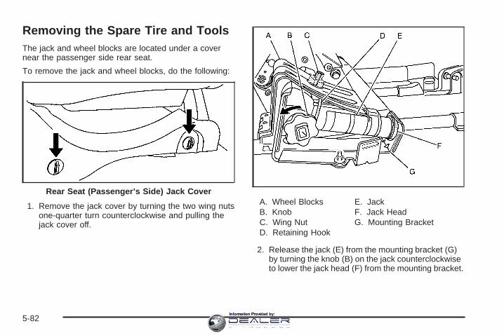
Removing the Spare Tire and ToolsThe jack and wheel blocks are located under a covernear the passenger side rear seat.
To remove the jack and wheel blocks, do the following:
1. Remove the jack cover by turning the two wing nutsone-quarter turn counterclockwise and pulling thejack cover off.
A. Wheel BlocksB. KnobC. Wing NutD. Retaining Hook
E. JackF. Jack HeadG. Mounting Bracket
2. Release the jack (E) from the mounting bracket (G)by turning the knob (B) on the jack counterclockwiseto lower the jack head (F) from the mounting bracket.
Rear Seat (Passenger’s Side) Jack Cover
5-82Information Provided by:
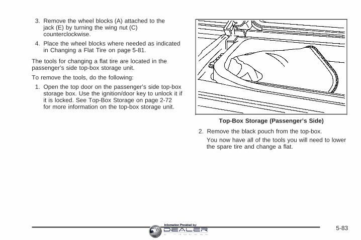
3. Remove the wheel blocks (A) attached to thejack (E) by turning the wing nut (C)counterclockwise.
4. Place the wheel blocks where needed as indicatedin Changing a Flat Tire on page 5-81.
The tools for changing a flat tire are located in thepassenger’s side top-box storage unit.
To remove the tools, do the following:
1. Open the top door on the passenger’s side top-boxstorage box. Use the ignition/door key to unlock it ifit is locked. See Top-Box Storage on page 2-72for more information on the top-box storage unit.
2. Remove the black pouch from the top-box.You now have all of the tools you will need to lowerthe spare tire and change a flat.
Top-Box Storage (Passenger’s Side)
5-83Information Provided by:

You will use the jack handle extensions and the wheelwrench to remove the underbody-mounted spare tire.
A. Spare Tire (ValveStem Pointed Down)
B. Hoist AssemblyC. Hoist CableD. Tire RetainerE. Hoist ShaftF. Hoist End of
Extension Tool
G. Hoist ShaftAccess Hole
H. Wheel WrenchI. Jack Handle
ExtensionsJ. Spare Tire Lock
(If Equipped)
To lower the spare tire, do the following:
1. Your vehicle may be equipped with a spare tirelock (J). Open the spare tire lock cover on thebumper and use the ignition key to remove the lock.
2. Assemble the wheel wrench (H) and the two jackhandle extensions (I) as shown.
5-84Information Provided by:

3. Insert the hoist end(open end) (F) of theextension throughthe hole (G) in therear bumper.
Be sure the hoist end of the extension connects tothe hoist shaft (E). The ribbed square end of theextension is used to lower the spare tire.
4. Turn the wheel wrench (H) counterclockwise tolower the spare tire to the ground. Continue toturn the wheel wrench until the spare tire can bepulled out from under the vehicle.If the spare tire does not lower to the ground,the secondary latch is engaged causing the tirenot to lower. See Secondary Latch Systemon page 5-93.
5. Pull the spare tiretowards you. Thewheel wrench has ahook that allows you topull the hoist cabletowards you to assistin reaching thespare tire.
6. Tilt the retainer at theend of the cable whenthe tire has beenlowered, so it can bepulled up throughthe wheel opening.
7. Put the spare tire near the flat tire.
5-85Information Provided by:
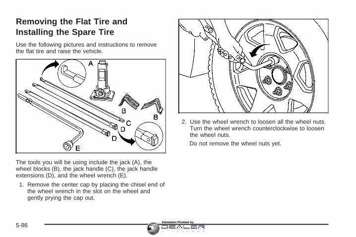
Removing the Flat Tire andInstalling the Spare TireUse the following pictures and instructions to removethe flat tire and raise the vehicle.
The tools you will be using include the jack (A), thewheel blocks (B), the jack handle (C), the jack handleextensions (D), and the wheel wrench (E).
1. Remove the center cap by placing the chisel end ofthe wheel wrench in the slot on the wheel andgently prying the cap out.
2. Use the wheel wrench to loosen all the wheel nuts.Turn the wheel wrench counterclockwise to loosenthe wheel nuts.Do not remove the wheel nuts yet.
5-86Information Provided by:

3. Refer to the above graphic which shows thegeneral area of jack placement, front position (A),and rear position (B). See the text and art followingfor the exact jack placement.
{CAUTION:
Getting under a vehicle when it is jacked up isdangerous. If the vehicle slips off the jack youcould be badly injured or killed. Never get undera vehicle when it is supported only by a jack.
Jack Positions (Overall View)
5-87Information Provided by:
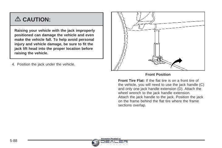
{CAUTION:
Raising your vehicle with the jack improperlypositioned can damage the vehicle and evenmake the vehicle fall. To help avoid personalinjury and vehicle damage, be sure to fit thejack lift head into the proper location beforeraising the vehicle.
4. Position the jack under the vehicle.
Front Tire Flat: If the flat tire is on a front tire ofthe vehicle, you will need to use the jack handle (C)and only one jack handle extension (D). Attach thewheel wrench to the jack handle extension.Attach the jack handle to the jack. Position the jackon the frame behind the flat tire where the framesections overlap.
Front Position
5-88Information Provided by:

Rear Tire Flat: If the flattire is on a rear tire of thevehicle, you will needto use the jack handle (C)and both jack handleextensions (D). Attach thewheel wrench to thejack handle extensions.Attach the jack handle tothe jack. Use thejacking pad provided onthe rear axle.
5. Turn the wheel wrench clockwise to raise thevehicle. Raise the vehicle far enough off the groundso there is enough room for the spare tire toclear the ground.
6. Remove all the wheelnuts and take off theflat tire.
Rear Position
5-89Information Provided by:

{CAUTION:
Rust or dirt on the wheel, or on the parts towhich it is fastened, can make the wheel nutsbecome loose after a time. The wheel couldcome off and cause an accident. When youchange a wheel, remove any rust or dirt fromthe places where the wheel attaches to thevehicle. In an emergency, you can use a clothor a paper towel to do this; but be sure to usea scraper or wire brush later, if needed, to getall the rust or dirt off.
7. Remove any rust or dirtfrom the wheel bolts,mounting surfacesand spare wheel.
8. Install the spare tire.
{CAUTION:
Never use oil or grease on studs or nuts. If youdo, the nuts might come loose. Your wheelcould fall off, causing a serious accident.
5-90Information Provided by:

9. Put the wheel nuts back on with the rounded end ofthe nuts toward the wheel after mounting the spare.
10. Tighten each wheel nut by hand. Then use thewheel wrench to tighten the wheel nuts until thewheel is held against the hub.
11. Turn the wheel wrenchcounterclockwise tolower the vehicle.Lower the jackcompletely.
Front Position
Rear Position1500 Series
5-91Information Provided by:

{CAUTION:
Incorrect wheel nuts or improperly tightenedwheel nuts can cause the wheel to come looseand even come off. This could lead to anaccident. Be sure to use the correct wheelnuts. If you have to replace them, be sure toget new GM original equipment wheel nuts.Stop somewhere as soon as you can and havethe nuts tightened with a torque wrench to theproper torque specification. See Capacitiesand Specifications on page 5-119 for wheel nuttorque specification.
Notice: Improperly tightened wheel nuts can leadto brake pulsation and rotor damage. To avoidexpensive brake repairs, evenly tighten the wheelnuts in the proper sequence and to the propertorque specification. See Capacities andSpecifications on page 5-119 for the wheel nuttorque specification.
12. Tighten the nuts firmlyin a crisscrosssequence as shown byturning the wheelwrench clockwise.
When you reinstall the regular wheel and tire, you mustalso reinstall the center cap. Place the cap on thewheel and tap it into place until it seats flush with thewheel. The cap only goes on one way. Be sure to line upthe tab on the center cap with the indentation on thewheel.
5-92Information Provided by:
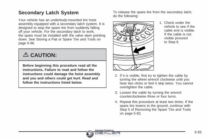
Secondary Latch SystemYour vehicle has an underbody-mounted tire hoistassembly equipped with a secondary latch system. It isdesigned to stop the spare tire from suddenly fallingoff your vehicle. For the secondary latch to work,the spare must be installed with the valve stem pointingdown. See Storing a Flat or Spare Tire and Tools onpage 5-96.
{CAUTION:
Before beginning this procedure read all theinstructions. Failure to read and follow theinstructions could damage the hoist assemblyand you and others could get hurt. Read andfollow the instructions listed below.
To release the spare tire from the secondary latch,do the following:
1. Check under thevehicle to see if thecable end is visible.If the cable is notvisible proceedto Step 6.
2. If it is visible, first try to tighten the cable byturning the wheel wrench clockwise until youhear two clicks or feel it skip twice. You cannotovertighten the cable.
3. Loosen the cable by turning the wrenchcounterclockwise three or four turns.
4. Repeat this procedure at least two times. If thespare tire lowers to the ground, continue withStep 5 of Removing the Spare Tire and Toolson page 5-82.
5-93Information Provided by:

5. If the spare does not lower, turn the wrenchcounterclockwise until approximately 6 inches(15 cm) of cable is exposed.
6. Stand the wheel blocks on their shortest ends,with the backs facing each other.
7. Place the bottom edgeof the jack (A) on thewheel blocks (B),separating them so thatthe jack is balancedsecurely.
8. Attach the jack handle, extension, and wheelwrench to the jack and place it (with the wheelblocks) under the vehicle toward the front of therear bumper.
5-94Information Provided by:

9. Position the center lift point of the jack under thecenter of the spare tire.
10. Turn the wrench clockwise to raise the jack until itlifts the end fitting.
11. Continue raising the jack until the spare tire stopsmoving upward and is held firmly in place.The secondary latch has released and the sparetire is balancing on the jack.
12. Lower the jack by turning the wheel wrenchcounterclockwise. Keep lowering the jack until thespare tire slides off the jack or is hanging bythe cable.
{CAUTION:
Someone standing too close during theprocedure could be injured by the jack. If thespare tire does not slide off the jack completely,make sure no one is behind you or on eitherside of you as you pull the jack out fromthe spare.
13. Disconnect the jack handle from the jack andcarefully remove the jack. Use one hand topush against the spare while firmly pulling the jackout from under the spare tire with the other hand.If the spare tire is hanging from the cable, insert thehoist handle, extension and wheel wrench intothe hoist shaft hole in the bumper and turnthe wheel wrench counterclockwise to lower thespare the rest of the way.
5-95Information Provided by:

14. Tilt the retainer at theend of the cable andpull it through thewheel opening. Pull thetire out from underthe vehicle.
15. Turn the wheel wrench in the hoist shaft hole in thebumper clockwise to raise the cable back up if thecable is hanging under the vehicle.
Have the hoist assembly inspected as soon as you can.You will not be able to store a spare or flat tire usingthe hoist assembly until it has been replaced.
To continue changing the flat tire, see Removing theFlat Tire and Installing the Spare Tire on page 5-86.
Storing a Flat or Spare Tireand Tools
{CAUTION:
Storing a jack, a tire, or other equipment in thepassenger compartment of the vehicle couldcause injury. In a sudden stop or collision,loose equipment could strike someone.Store all these in the proper place.
Notice: Storing an aluminum wheel with a flat tireunder your vehicle for an extended period of time orwith the valve stem pointing up may damage thewheel. Always stow the wheel with the valvestem pointing down and have the wheel/tire repairedas soon as possible.
5-96Information Provided by:

Store the tire under the rear of the vehicle in the sparetire carrier. Use the art and text following to help you:
A. Spare Tire (ValveStem Pointed Down)
B. Hoist AssemblyC. Hoist CableD. Tire RetainerE. Hoist ShaftF. Hoist End of
Extension Tool
G. Hoist ShaftAccess Hole
H. Wheel WrenchI. Jack Handle
ExtensionsJ. Spare Tire Lock
(If Equipped)
1. Put the tire on the ground at the rear of the vehiclewith the valve stem pointed down and toward therear of the vehicle.
2. Tilt the retainerdownward and throughthe wheel opening.Make sure the retaineris fully seated acrossthe underside ofthe wheel.
3. Attach the wheel wrench (H) and extensions (I)together.
5-97Information Provided by:

4. Insert the hoist end (F)through the hole (G) inthe rear bumper andinto the hoist shaft.
5. Raise the tire partway upward. Make sure theretainer is seated in the wheel opening.
6. Raise the tire fully against the underside of thevehicle by turning the wheel wrench clockwiseuntil you hear two clicks or feel it skip twice.The cable cannot be overtightened.
7. Make sure the tire is stored securely. Push, pull (A),and then try to turn (B) the tire. If the tire moves,use the wheel wrench to tighten the cable. Reinstallthe spare tire lock (if equipped).
5-98Information Provided by:

To store the jack and tools, do the following:
1. Return the tools to the tool bag and place it back inthe top-box storage area.
2. Assemble the wheel blocks and jack together withthe wing nut by reversing Step 2 under Removingthe Spare Tire and Tools on page 5-82.
3. Replace the jack cover and tighten the jack-coverwing nuts.
Spare TireYour vehicle, when new, had a fully-inflated spare tire.A spare tire may lose air over time, so check itsinflation pressure regularly. See Inflation - Tire Pressureon page 5-66 and Loading Your Vehicle on page 4-44for information regarding proper tire inflation and loadingyour vehicle. For instruction on how to remove, installor store a spare tire, see Removing the Flat Tireand Installing the Spare Tire on page 5-86 and Storinga Flat or Spare Tire and Tools on page 5-96.
After installing the spare tire on your vehicle, you shouldstop as soon as possible and make sure the spare iscorrectly inflated. Have the damaged or flat roadtire repaired or replaced as soon as you can andinstalled back onto your vehicle. This way, a spare tirewill be available in case you need it again.
Your vehicle may have a different size spare tire thanthe road tires, those originally installed on your vehicle.This spare tire was developed for use on your vehicle,so it is all right to drive on it.
5-99Information Provided by:

Appearance Care
Cleaning the Inside of Your VehicleYour vehicle’s interior will continue to look its best ifit is cleaned often. Although not always visible, dust anddirt can accumulate on your upholstery. Dirt candamage carpet, fabric, leather, and plastic surfaces.Regular vacuuming is recommended to remove particlesfrom your upholstery. It is important to keep yourupholstery from becoming and remaining heavily soiled.Soils should be removed as quickly as possible.Your vehicle’s interior may experience extremes of heatthat could cause stains to set rapidly.
Lighter colored interiors may require more frequentcleaning. Use care because newspapers and garmentsthat transfer color to your home furnishings may alsotransfer color to your vehicle’s interior.
When cleaning your vehicle’s interior, only use cleanersspecifically designed for the surfaces being cleaned.Permanent damage may result from using cleanerson surfaces for which they were not intended.
Use glass cleaner only on glass. Remove any accidentalover-spray from other surfaces immediately. To preventover-spray, apply cleaner directly to the cleaning cloth.
Notice: If you use abrasive cleaners when cleaningglass surfaces on your vehicle, you could scratchthe glass and/or cause damage to the rear windowdefogger. When cleaning the glass on yourvehicle, use only a soft cloth and glass cleaner.
Many cleaners contain solvents that may becomeconcentrated in your vehicle’s breathing space.Before using cleaners, read and adhere to all safetyinstructions on the label. While cleaning your vehicle’sinterior, maintain adequate ventilation by openingyour vehicle’s doors and windows.
Dust may be removed from small buttons and knobsusing a small brush with soft bristles.
Your GM dealer has a product for cleaning yourvehicle’s glass. Should it become necessary, you canalso obtain a product from your GM dealer to removeodors from your vehicle’s upholstery.
5-100Information Provided by:

Do not clean your vehicle using the following cleanersor techniques:
• Never use a knife or any other sharp object toremove a soil from any interior surface.
• Never use a stiff brush. It can cause damage toyour vehicle’s interior surfaces.
• Never apply heavy pressure or rub aggressivelywith a cleaning cloth. Use of heavy pressurecan damage your interior and does not improve theeffectiveness of soil removal.
• Use only mild, neutral-pH soaps. Avoid laundrydetergents or dishwashing soaps with degreasers.Using too much soap will leave a residue thatleaves streaks and attracts dirt. For liquid cleaners,about 20 drops per gallon (3.78 L) of water is agood guide.
• Do not heavily saturate your upholstery whilecleaning.
• Damage to your vehicle’s interior may result fromthe use of many organic solvents such as naptha,alcohol, etc.
Fabric/CarpetUse a vacuum cleaner with a soft brush attachmentfrequently to remove dust and loose dirt. A canistervacuum with a beater bar in the nozzle may only be usedon floor carpet and carpeted floor mats. For soils, alwaystry to remove them first with plain water or club soda.Before cleaning, gently remove as much of the soil aspossible using one of the following techniques:• For liquids: gently blot the remaining soil with a
paper towel. Allow the soil to absorb into the papertowel until no more can be removed.
• For solid dry soils: remove as much as possible andthen vacuum.
To clean, use the following instructions:
1. Saturate a lint-free, clean white cloth with water orclub soda.
2. Wring the cloth to remove excess moisture.
3. Start on the outside edge of the soil and gently rubtoward the center. Continue cleaning, using a cleanarea of the cloth each time it becomes soiled.
4. Continue to gently rub the soiled area until thecleaning cloth remains clean.
5. If the soil is not completely removed, use a mildsoap solution and repeat the cleaning processthat was used with plain water.
5-101Information Provided by:

If any of the soil remains, a commercial fabric cleaner orspot lifter may be necessary. When a commercialupholstery cleaner or spot lifter is to be used, test asmall hidden area for colorfastness first. If the locallycleaned area gives any impression that a ring formationmay result, clean the entire surface.
After the cleaning process has been completed, a papertowel can be used to blot excess moisture from thefabric or carpet.
LeatherA soft cloth dampened with water may be used toremove dust. If a more thorough cleaning is necessary,a soft cloth dampened with a mild soap solution canbe used. Allow the leather to dry naturally. Do not useheat to dry. Never use steam to clean leather. Neveruse spot lifters or spot removers on leather. Manycommercial leather cleaners and coatings that are soldto preserve and protect leather may permanentlychange the appearance and feel of your leather and arenot recommended. Do not use silicone or wax-basedproducts, or those containing organic solvents to cleanyour vehicle’s interior because they can alter theappearance by increasing the gloss in a non-uniformmanner. Never use shoe polish on your leather.
Instrument Panel, Vinyl, and OtherPlastic SurfacesA soft cloth dampened with water may be used toremove dust. If a more thorough cleaning is necessary,a clean soft cloth dampened with a mild soap solutioncan be used to gently remove dust and dirt. Never usespot lifters or removers on plastic surfaces. Manycommercial cleaners and coatings that are sold topreserve and protect soft plastic surfaces maypermanently change the appearance and feel of yourinterior and are not recommended. Do not use siliconeor wax-based products, or those containing organicsolvents to clean your vehicle’s interior becausethey can alter the appearance by increasing the gloss ina non-uniform manner.
Some commercial products may increase gloss on yourinstrument panel. The increase in gloss may causeannoying reflections in the windshield and even make itdifficult to see through the windshield under certainconditions.
5-102Information Provided by:

Wood PanelsUse a clean cloth moistened in warm, soapy water(use mild dish washing soap). Dry the wood immediatelywith a clean cloth.
Speaker CoversVacuum around a speaker cover gently, so that thespeaker will not be damaged. Clean spots withjust water and mild soap.
Care of Safety BeltsKeep belts clean and dry.
{CAUTION:
Do not bleach or dye safety belts. If you do,it may severely weaken them. In a crash,they might not be able to provide adequateprotection. Clean safety belts only with mildsoap and lukewarm water.
WeatherstripsSilicone grease on weatherstrips will make them lastlonger, seal better, and not stick or squeak. Applysilicone grease with a clean cloth. During very cold,damp weather frequent application may be required.See Recommended Fluids and Lubricants on page 6-12.
Washing Your VehicleThe paint finish on the vehicle provides beauty, depth ofcolor, gloss retention, and durability.
The best way to preserve the vehicle’s finish is to keep itclean by washing it often with lukewarm or cold water.
Do not wash the vehicle in the direct rays of the sun.Use a car washing soap. Do not use strong soapsor chemical detergents. Be sure to rinse the vehicle well,removing all soap residue completely. GM-approvedcleaning products can be obtained from your dealer.See Vehicle Care/Appearance Materials on page 5-107.Do not use cleaning agents that are petroleum based,or that contain acid or abrasives. All cleaning agentsshould be flushed promptly and not allowed to dry on thesurface, or they could stain. Dry the finish with a soft,clean chamois or an all-cotton towel to avoid surfacescratches and water spotting.
High pressure car washes may cause water to enterthe vehicle.
5-103Information Provided by:

Cleaning Exterior Lamps/LensesUse only lukewarm or cold water, a soft cloth and acar washing soap to clean exterior lamps and lenses.Follow instructions under Washing Your Vehicle onpage 5-103.
Finish CareOccasional waxing or mild polishing of your vehicle byhand may be necessary to remove residue from thepaint finish. You can get GM-approved cleaning productsfrom your dealer. See Vehicle Care/AppearanceMaterials on page 5-107.
If your vehicle has a “basecoat/clearcoat” paint finish,the clearcoat gives more depth and gloss to the coloredbasecoat. Always use waxes and polishes that arenon-abrasive and made for a basecoat/clearcoatpaint finish.
Notice: Machine compounding or aggressivepolishing on a basecoat/clearcoat paint finish maydamage it. Use only non-abrasive waxes andpolishes that are made for a basecoat/clearcoatpaint finish on your vehicle.
Foreign materials such as calcium chloride and othersalts, ice melting agents, road oil and tar, tree sap, birddroppings, chemicals from industrial chimneys, etc.,can damage your vehicle’s finish if they remainon painted surfaces. Wash the vehicle as soon aspossible. If necessary, use non-abrasive cleaners thatare marked safe for painted surfaces to removeforeign matter.
Exterior painted surfaces are subject to aging, weatherand chemical fallout that can take their toll over aperiod of years. You can help to keep the paint finishlooking new by keeping your vehicle garaged or coveredwhenever possible.
Protecting Exterior Bright Metal PartsBright metal parts should be cleaned regularly to keeptheir luster. Washing with water is all that is usuallyneeded. However, you may use chrome polish onchrome or stainless steel trim, if necessary.
Use special care with aluminum trim. To avoid damagingprotective trim, never use auto or chrome polish,steam or caustic soap to clean aluminum. A coating ofwax, rubbed to high polish, is recommended for allbright metal parts.
5-104Information Provided by:

Windshield and Wiper BladesIf the windshield is not clear after using the windshieldwasher, or if the wiper blade chatters when running, wax,sap, or other material may be on the blade or windshield.
Clean the outside of the windshield with a glass cleaningliquid or powder and water solution. The windshield isclean if beads do not form when it is rinsed with water.
Grime from the windshield will stick to the wiper bladesand affect their performance. Clean the blade by wipingvigorously with a cloth soaked in full-strength windshieldwasher solvent. Then rinse the blade with water.
Check the wiper blades and clean them as necessary;replace blades that look worn.
Aluminum or Chrome-Plated WheelsThe vehicle may be equipped with either aluminum orchrome-plated wheels.
Keep the wheels clean using a soft clean cloth with mildsoap and water. Rinse with clean water. After rinsingthoroughly, dry with a soft clean towel. A wax may thenbe applied.
Notice: If you use strong soaps, chemicals,abrasive polishes, cleaners, brushes, or cleanersthat contain acid on aluminum or chrome-platedwheels, you could damage the surface of the
wheel(s). The repairs would not be covered by yourwarranty. Use only GM-approved cleaners onaluminum or chrome-plated wheels.
The surface of these wheels is similar to the paintedsurface of your vehicle. Do not use strong soaps,chemicals, abrasive polishes, abrasive cleaners,cleaners with acid, or abrasive cleaning brushes onthem because you could damage the surface. Do notuse chrome polish on aluminum wheels.
Notice: Using chrome polish on aluminum wheelscould damage the wheels. The repairs would notbe covered by your warranty. Use chrome polish onchrome wheels only.
Use chrome polish only on chrome-plated wheels, butavoid any painted surface of the wheel, and buff offimmediately after application.
Notice: If you drive your vehicle through anautomatic car wash that has silicone carbide tirecleaning brushes, you could damage the aluminumor chrome-plated wheels. The repairs would notbe covered by your warranty. Never drive a vehicleequipped with aluminum or chrome-plated wheelsthrough an automatic car wash that uses siliconecarbide tire cleaning brushes.
Do not take your vehicle through an automatic car washthat has silicone carbide tire cleaning brushes. Thesebrushes can also damage the surface of these wheels.
5-105Information Provided by:

TiresTo clean the tires, use a stiff brush with tire cleaner.
Notice: Using petroleum-based tire dressingproducts on your vehicle may damage the paintfinish and/or tires. When applying a tire dressing,always wipe off any overspray from all paintedsurfaces on your vehicle.
Sheet Metal DamageIf the vehicle is damaged and requires sheet metalrepair or replacement, make sure the body repair shopapplies anti-corrosion material to parts repaired orreplaced to restore corrosion protection.
Original manufacturer replacement parts will provide thecorrosion protection while maintaining the warranty.
Finish DamageAny stone chips, fractures or deep scratches in the finishshould be repaired right away. Bare metal will corrodequickly and may develop into major repair expense.
Minor chips and scratches can be repaired with touch-upmaterials available from your GM dealer. Larger areasof finish damage can be corrected in your GM dealer’sbody and paint shop.
Underbody MaintenanceChemicals used for ice and snow removal and dustcontrol can collect on the underbody. If these are notremoved, corrosion and rust can develop on theunderbody parts such as fuel lines, frame, floor pan,and exhaust system even though they have corrosionprotection.
At least every spring, flush these materials from theunderbody with plain water. Clean any areas where mudand debris can collect. Dirt packed in close areas ofthe frame should be loosened before being flushed.Your dealer or an underbody car washing system cando this for you.
Chemical Paint SpottingSome weather and atmospheric conditions can create achemical fallout. Airborne pollutants can fall upon andattack painted surfaces on the vehicle. This damage cantake two forms: blotchy, ring-shaped discolorations, andsmall, irregular dark spots etched into the paint surface.
Although no defect in the paint job causes this, GM willrepair, at no charge to the owner, the surfaces ofnew vehicles damaged by this fallout condition within12 months or 12,000 miles (20 000 km) of purchase,whichever occurs first.
5-106Information Provided by:
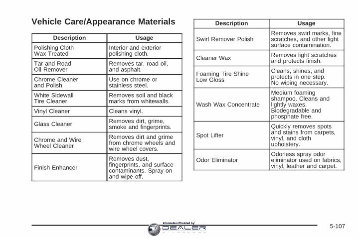
Vehicle Care/Appearance Materials
Description Usage
Polishing ClothWax-Treated
Interior and exteriorpolishing cloth.
Tar and RoadOil Remover
Removes tar, road oil,and asphalt.
Chrome Cleanerand Polish
Use on chrome orstainless steel.
White SidewallTire Cleaner
Removes soil and blackmarks from whitewalls.
Vinyl Cleaner Cleans vinyl.
Glass Cleaner Removes dirt, grime,smoke and fingerprints.
Chrome and WireWheel Cleaner
Removes dirt and grimefrom chrome wheels andwire wheel covers.
Finish Enhancer
Removes dust,fingerprints, and surfacecontaminants. Spray onand wipe off.
Description Usage
Swirl Remover PolishRemoves swirl marks, finescratches, and other lightsurface contamination.
Cleaner Wax Removes light scratchesand protects finish.
Foaming Tire ShineLow Gloss
Cleans, shines, andprotects in one step.No wiping necessary.
Wash Wax Concentrate
Medium foamingshampoo. Cleans andlightly waxes.Biodegradable andphosphate free.
Spot Lifter
Quickly removes spotsand stains from carpets,vinyl, and clothupholstery.
Odor EliminatorOdorless spray odoreliminator used on fabrics,vinyl, leather and carpet.
5-107Information Provided by:

Vehicle Identification
Vehicle Identification Number (VIN)
This is the legal identifier for your vehicle. It appears ona plate in the front corner of the instrument panel, onthe driver’s side. You can see it if you look through thewindshield from outside your vehicle. The VIN alsoappears on the Vehicle Certification and Service Partslabels and the certificates of title and registration.
Engine IdentificationThe eighth character in the VIN is the engine code.This code will help you identify your vehicle’s engine,specifications, and replacement parts.
Service Parts Identification LabelYou will find this label on the inside of the glove box.It is very helpful if you ever need to order parts.On this label, you will find the following:
• VIN
• Model designation
• Paint information
• Production options and special equipment
Be sure that this label is not removed from the vehicle.
5-108Information Provided by:
Electrical System
Add-On Electrical EquipmentNotice: Don’t add anything electrical to yourvehicle unless you check with your dealer first.Some electrical equipment can damage your vehicleand the damage wouldn’t be covered by yourwarranty. Some add-on electrical equipment cankeep other components from working as theyshould.
Your vehicle has an airbag system. Before attempting toadd anything electrical to your vehicle, see ServicingYour Airbag-Equipped Vehicle on page 1-64.
Windshield Wiper FusesThe windshield wiper motor is protected by an internalcircuit breaker and a fuse. If the motor overheats due toheavy snow, etc., the wiper will stop until the motorcools. If the overload is caused by some electricalproblem and not snow, etc., be sure to get it fixed.
Power Windows and OtherPower OptionsCircuit breakers protect the power windows and otherpower accessories. When the current load is too heavy,the circuit breaker opens and closes, protecting thecircuit until the problem is fixed or goes away.
Fuses and Circuit BreakersThe wiring circuits in your vehicle are protected fromshort circuits by a combination of fuses, circuit breakersand fusible thermal links. This greatly reduces thechance of fires caused by electrical problems.
Look at the silver-colored band inside the fuse. If theband is broken or melted, replace the fuse. Be sure youreplace a bad fuse with a new one of the identicalsize and rating.
If you ever have a problem on the road and don’t havea spare fuse, you can borrow one that has the sameamperage. Just pick some feature of your vehiclethat you can get along without – like the radio orcigarette lighter – and use its fuse, if it is the correctamperage. Replace it as soon as you can.
5-109Information Provided by:

Instrument Panel Fuse BlockThe fuse block accessdoor is on the driver’s sideedge of the instrumentpanel. Pull off the cover toaccess the fuse block.
To remove fuses if you don’t have a fuse extractor, holdthe end of the fuse between your thumb and indexfinger and pull straight out.
You may have spare fuses located behind the fuseblock access door. These can be used to replace a badfuse. However, make sure it is of the correct amperage.
Fuses Usage
RR Wiper Not Used
SEO ACCY Special Equipment OptionAccessory
WS WPR Windshield Wipers
5-110Information Provided by:
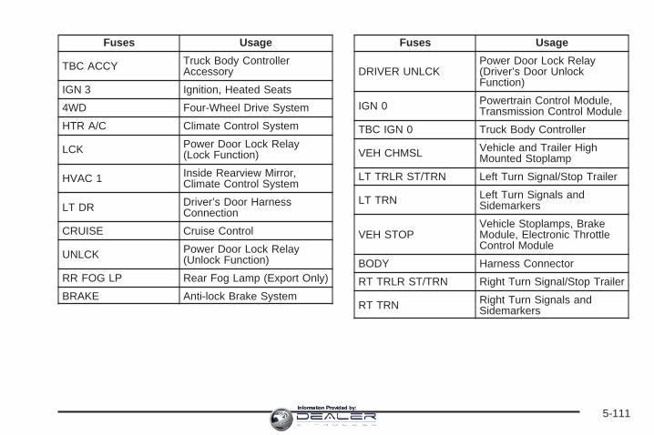
Fuses Usage
TBC ACCY Truck Body ControllerAccessory
IGN 3 Ignition, Heated Seats
4WD Four-Wheel Drive System
HTR A/C Climate Control System
LCK Power Door Lock Relay(Lock Function)
HVAC 1 Inside Rearview Mirror,Climate Control System
LT DR Driver’s Door HarnessConnection
CRUISE Cruise Control
UNLCK Power Door Lock Relay(Unlock Function)
RR FOG LP Rear Fog Lamp (Export Only)
BRAKE Anti-lock Brake System
Fuses Usage
DRIVER UNLCKPower Door Lock Relay(Driver’s Door UnlockFunction)
IGN 0 Powertrain Control Module,Transmission Control Module
TBC IGN 0 Truck Body Controller
VEH CHMSL Vehicle and Trailer HighMounted Stoplamp
LT TRLR ST/TRN Left Turn Signal/Stop Trailer
LT TRN Left Turn Signals andSidemarkers
VEH STOPVehicle Stoplamps, BrakeModule, Electronic ThrottleControl Module
BODY Harness Connector
RT TRLR ST/TRN Right Turn Signal/Stop Trailer
RT TRN Right Turn Signals andSidemarkers
5-111Information Provided by:

Fuses Usage
DDM Driver Door Module
AUX PWR 2, M/GATE Rear Cargo Area PowerOutlets, Midgate
LCKS Power Door Lock System
ECC, TPM
Rear Electronic ClimateControl, Tire PressureMonitoring System(If Equipped)
TBC 2C Truck Body Controller
HAZRD Flasher Module
CB LT DRS Left Power WindowCircuit Breaker
TBC 2B Truck Body Controller
TBC 2A Truck Body Controller
Center Instrument Panel Fuse BlockThe center instrument panel utility block is locatedunderneath the instrument panel, to the left of thesteering column.
5-112Information Provided by:
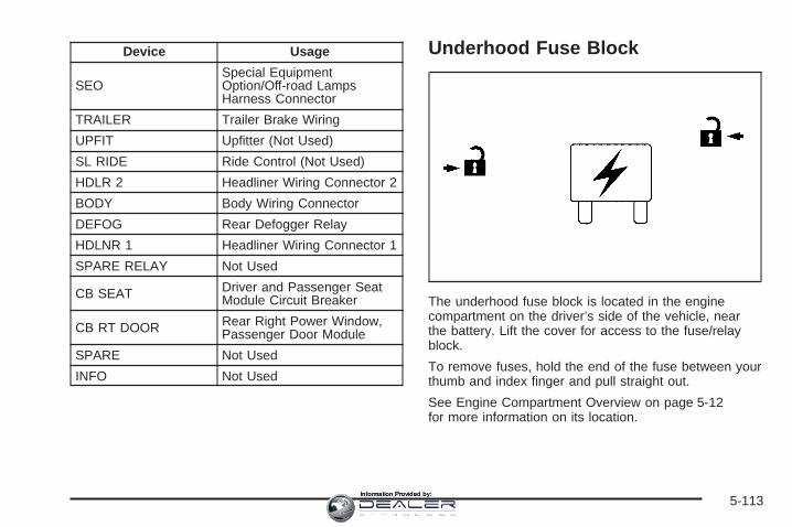
Device Usage
SEOSpecial EquipmentOption/Off-road LampsHarness Connector
TRAILER Trailer Brake Wiring
UPFIT Upfitter (Not Used)
SL RIDE Ride Control (Not Used)
HDLR 2 Headliner Wiring Connector 2
BODY Body Wiring Connector
DEFOG Rear Defogger Relay
HDLNR 1 Headliner Wiring Connector 1
SPARE RELAY Not Used
CB SEAT Driver and Passenger SeatModule Circuit Breaker
CB RT DOOR Rear Right Power Window,Passenger Door Module
SPARE Not Used
INFO Not Used
Underhood Fuse Block
The underhood fuse block is located in the enginecompartment on the driver’s side of the vehicle, nearthe battery. Lift the cover for access to the fuse/relayblock.
To remove fuses, hold the end of the fuse between yourthumb and index finger and pull straight out.
See Engine Compartment Overview on page 5-12for more information on its location.
5-113Information Provided by:

5-114Information Provided by:

*1 — Gasoline Engine and Fuel Injection Rail #2.
*2 — Gasoline Engine and Fuel Injection Rail #1.
*3 — Gasoline Engine; Oxygen Sensors.
*4 — Gasoline Engine; Oxygen Sensors.
*5 — Ignition 1
*6 — Powertrain Control Module, Fuel Pump.
*7 — Rear Climate Control.
*8 — Sunroof.
Fuses Usage
GLOW PLUG Not Used
CUST FEED Accessory Power
HYBRID Not Used
STUD #1 Auxiliary Power
MBECMid-Bussed Electrical CenterPower Feed, Front Seats,Right Doors
BLWR Front Climate Control Fan
Fuses Usage
LBEC
Left Bussed Electrical Center,Door Modules, Door Locks,Auxiliary Power Outlet—RearCargo Area and InstrumentPanel
STUD #2* Accessory Power/TrailerWiring Brake Feed
ABS Anti-lock Brakes
VSES/ECAS Automatic Level Control(ALC) Compressor
IGN A Ignition Power
IGN B Ignition Power
LBEC 1Left Bussed Electrical Center,Left Doors, Truck BodyController, Flasher Module
TRL PARK Parking Lamps Trailer Wiring
RR PARK Right Rear Parking andSidemarker Lamps
LR PARK Left Rear Parking andSidemarker Lamps
5-115Information Provided by:

Fuses Usage
PARK LP Parking Lamps Relay
STRTR Starter Relay
INTPARK Interior Lamps
STOP LP Stoplamps
TBC BATT Truck Body ControllerBattery Feed
SEO B2 Off-Road Lamps
4WS Not Used
AUX PWR Accessory PowerOutlet — Console
PCM 1 Powertrain Control Module
ETC/ECM Electronic Throttle Control,Electronic Brake Controller
IGN E
Instrument Panel Cluster,Air Conditioning Relay,Turn Signal/Hazard Switch,Starter Relay
RTDElectronic SuspensionControl, Automatic LevelControl (ALC) Exhaust
TRL B/U Backup Lamps Trailer Wiring
Fuses Usage
F/PMP Fuel Pump (Relay)
B/U LPBack-up Lamps, AutomaticTransmission Shift LockControl System
RR DEFOG Rear Window Defogger
HDLP-HI Headlamp High Beam Relay
PRIME Not Used
AIRBAG Supplemental InflatableRestraint System
FRT PARK Front Parking Lamps,Sidemarker Lamps
DRL Daytime Running LampsRelay
SEO IGN Rear Defog Relay
TBC IGN1 Truck Body Controller Ignition
HI HDLP-LT Driver’s Side High BeamHeadlamp
LH HID Left Hand High IntensityDischarge Lamps
DRL Daytime Running Lamps
5-116Information Provided by:

Fuses Usage
RVC Regulated Voltage Control
IPC/DICInstrument PanelCluster/Driver InformationCenter
HVAC/ECAS Climate Control Controller
CIG LTR Cigarette Lighter
HI HDLP-RT Passenger’s Side High BeamHeadlamp
HDLP-LOW Headlamp Low Beam Relay
A/C COMP Air Conditioning CompressorRelay
A/C COMP Air Conditioning Compressor
TCMB Transmission Control Module
RR WPR Not Used
RADIO Audio System
SEO B1Mid Bussed Electrical Center,Universal Home RemoteSystem, Rear Heated Seats
LO HDLP-LT Driver’s Side HeadlampLow Beam
Fuses Usage
BTSI Brake Transmission ShiftInterlock System
CRNK Starting System
LO HDLP-RT Passenger’s Side HeadlampLow Beam
FOG LP Fog Lamp Relay
FOG LP Fog Lamps
HORN Horn Relay
W/S WASH Not Used
W/S WASH Not Used
INFO OnStar®/Rear SeatEntertainment
RADIO AMP Radio Amplifier
RH HID Right Hand High IntensityDischarge Lamp
HORN Horn Fuse
EAP Electric Adjustable Pedals
TREC All-Wheel Drive Module(If Equipped)
SBA Supplemental Brake Assist
5-117Information Provided by:
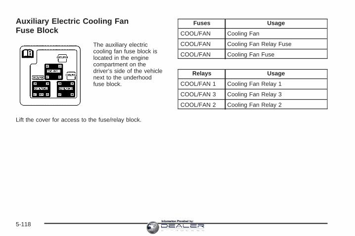
Auxiliary Electric Cooling FanFuse Block
The auxiliary electriccooling fan fuse block islocated in the enginecompartment on thedriver’s side of the vehiclenext to the underhoodfuse block.
Lift the cover for access to the fuse/relay block.
Fuses Usage
COOL/FAN Cooling Fan
COOL/FAN Cooling Fan Relay Fuse
COOL/FAN Cooling Fan Fuse
Relays Usage
COOL/FAN 1 Cooling Fan Relay 1
COOL/FAN 3 Cooling Fan Relay 3
COOL/FAN 2 Cooling Fan Relay 2
5-118Information Provided by:
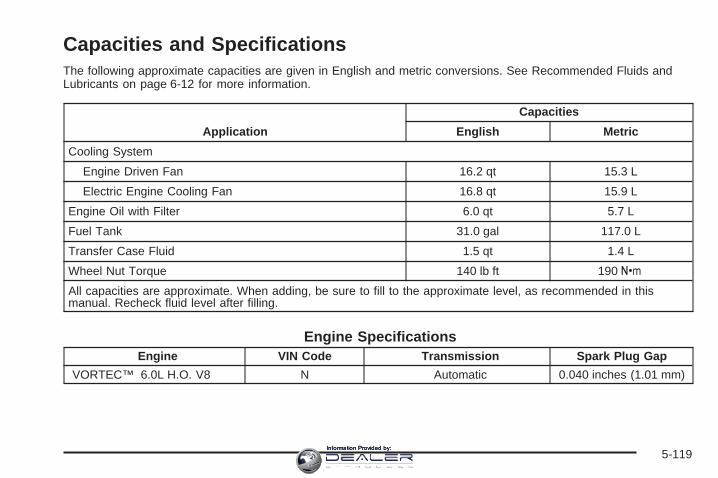
Capacities and SpecificationsThe following approximate capacities are given in English and metric conversions. See Recommended Fluids andLubricants on page 6-12 for more information.
Application
Capacities
English Metric
Cooling System
Engine Driven Fan 16.2 qt 15.3 L
Electric Engine Cooling Fan 16.8 qt 15.9 L
Engine Oil with Filter 6.0 qt 5.7 L
Fuel Tank 31.0 gal 117.0 L
Transfer Case Fluid 1.5 qt 1.4 L
Wheel Nut Torque 140 lb ft 190 Y
All capacities are approximate. When adding, be sure to fill to the approximate level, as recommended in thismanual. Recheck fluid level after filling.
Engine SpecificationsEngine VIN Code Transmission Spark Plug Gap
VORTEC™ 6.0L H.O. V8 N Automatic 0.040 inches (1.01 mm)
5-119Information Provided by:

✍ NOTES
5-120Information Provided by:
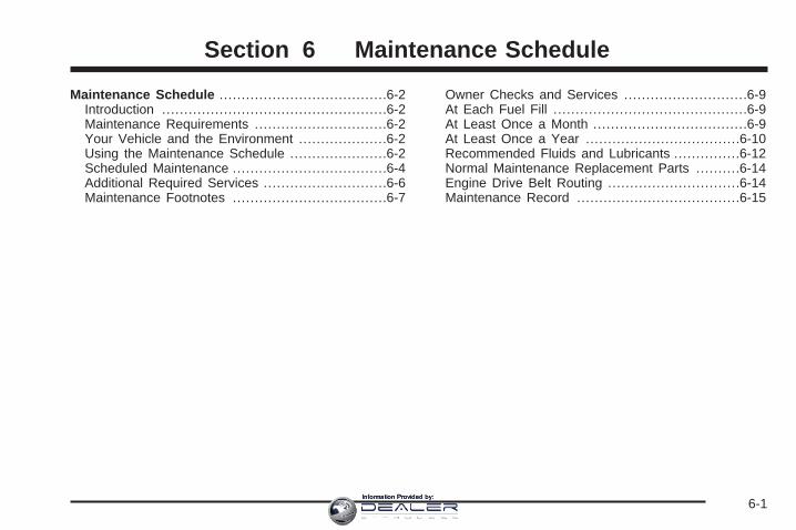
Maintenance Schedule ......................................6-2Introduction ...................................................6-2Maintenance Requirements ..............................6-2Your Vehicle and the Environment ....................6-2Using the Maintenance Schedule ......................6-2Scheduled Maintenance ...................................6-4Additional Required Services ............................6-6Maintenance Footnotes ...................................6-7
Owner Checks and Services ............................6-9At Each Fuel Fill ............................................6-9At Least Once a Month ...................................6-9At Least Once a Year ...................................6-10Recommended Fluids and Lubricants ...............6-12Normal Maintenance Replacement Parts ..........6-14Engine Drive Belt Routing ..............................6-14Maintenance Record .....................................6-15
Section 6 Maintenance Schedule
6-1Information Provided by:

Maintenance Schedule
IntroductionImportant: Keep engine oil at the proper level andchange as recommended.
Have you purchased the GM Protection Plan? The Plansupplements your new vehicle warranties. See yourWarranty and Owner Assistance booklet or your dealerfor details.
Maintenance RequirementsNotice: Maintenance intervals, checks, inspections,replacement parts, and recommended fluids andlubricants as prescribed in this manual are necessaryto keep your vehicle in good working condition.Any damage caused by failure to follow scheduledmaintenance may not be covered by warranty.
Your Vehicle and the EnvironmentProper vehicle maintenance not only helps to keep yourvehicle in good working condition, but also helps theenvironment. All recommended maintenance isimportant. Improper vehicle maintenance can evenaffect the quality of the air we breathe. Improper fluidlevels or the wrong tire inflation can increase the level ofemissions from your vehicle. To help protect ourenvironment, and to keep your vehicle in good condition,be sure to maintain your vehicle properly.
Using the Maintenance ScheduleWe at General Motors want to help you keep yourvehicle in good working condition. But we do not knowexactly how you will drive it. You may drive veryshort distances only a few times a week. Or you maydrive long distances all the time in very hot, dustyweather. You may use your vehicle in making deliveries.Or you may drive it to work, to do errands, or in manyother ways.
6-2Information Provided by:

Because of all the different ways people use theirvehicles, maintenance needs vary. You may need morefrequent checks and replacements. So please readthe following and note how you drive. If you have anyquestions on how to keep your vehicle in good condition,see your GM Goodwrench® dealer.
This schedule is for vehicles that:
• carry passengers and cargo within recommendedlimits. You will find these limits on the tire andloading information label. See Loading Your Vehicleon page 4-44.
• are driven on reasonable road surfaces within legaldriving limits.
• are driven off-road in the recommended manner.See Off-Road Driving on page 4-17.
• use the recommended fuel. See Gasoline Octaneon page 5-5.
The services in Scheduled Maintenance on page 6-4should be performed when indicated. See AdditionalRequired Services on page 6-6 and MaintenanceFootnotes on page 6-7 for further information.
{CAUTION:
Performing maintenance work on a vehiclecan be dangerous. In trying to do some jobs,you can be seriously injured. Do your ownmaintenance work only if you have the requiredknow-how and the proper tools and equipmentfor the job. If you have any doubt, see yourGM Goodwrench ® dealer to have a qualifiedtechnician do the work. See Doing Your OwnService Work on page 5-4.
Some maintenance services can be complex. So,unless you are technically qualified and have thenecessary equipment, you should have yourGM Goodwrench® dealer do these jobs.
When you go to your GM Goodwrench® dealer for yourservice needs, you will know that GM-trained andsupported service technicians will perform the workusing genuine GM parts.
If you want to purchase service information, see ServicePublications Ordering Information on page 7-14.
Owner Checks and Services on page 6-9 tells you whatshould be checked, when to check it, and what you caneasily do to help keep your vehicle in good condition.
6-3Information Provided by:

The proper replacement parts, fluids, and lubricants touse are listed in Recommended Fluids and Lubricantson page 6-12 and Normal Maintenance ReplacementParts on page 6-14. When your vehicle is serviced,make sure these are used. All parts should be replacedand all necessary repairs done before you or anyoneelse drives the vehicle. We recommend the use ofgenuine GM parts.
Scheduled MaintenanceWhen the CHANGE ENGINE OIL message comes on,it means that service is required for your vehicle.Have your vehicle serviced as soon as possible within thenext 600 miles (1 000 km). It is possible that, if you aredriving under the best conditions, the engine oil lifesystem may not indicate that vehicle service is necessaryfor over a year. However, your engine oil and filter mustbe changed at least once a year and at this time thesystem must be reset. Your GM Goodwrench® dealer hasGM-trained service technicians who will perform this workusing genuine GM parts and reset the system.
If the engine oil life system is ever reset accidentally,you must service your vehicle within 3,000 miles(5 000 km) since your last service. Remember to resetthe oil life system whenever the oil is changed. SeeEngine Oil Life System on page 5-17 for information onthe Engine Oil Life System and resetting the system.
When the CHANGE ENGINE OIL message appears,certain services, checks, and inspections are required.Required services are described in the following for“Maintenance I” and “Maintenance II.” Generally,it is recommended that your first service beMaintenance I, your second service be Maintenance II,and that you alternate Maintenance I and Maintenance IIthereafter. However, in some cases, Maintenance IImay be required more often.
Maintenance I — Use Maintenance I if the CHANGEENGINE OIL message comes on within 10 months sincethe vehicle was purchased or Maintenance II wasperformed.
Maintenance II — Use Maintenance II if the previousservice performed was Maintenance I. Always useMaintenance II whenever the message comes on10 months or more since the last service or if themessage has not come on at all for one year.
6-4Information Provided by:
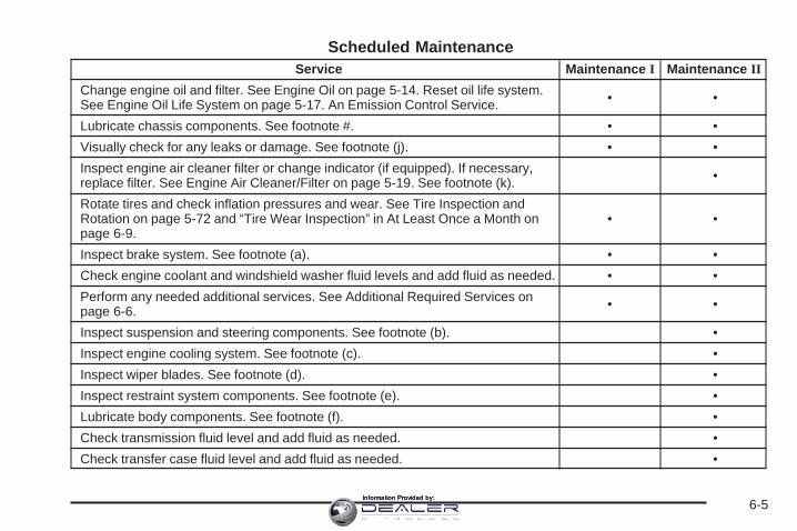
Scheduled MaintenanceService Maintenance I Maintenance II
Change engine oil and filter. See Engine Oil on page 5-14. Reset oil life system.See Engine Oil Life System on page 5-17. An Emission Control Service. • •
Lubricate chassis components. See footnote #. • •Visually check for any leaks or damage. See footnote (j). • •Inspect engine air cleaner filter or change indicator (if equipped). If necessary,replace filter. See Engine Air Cleaner/Filter on page 5-19. See footnote (k). •
Rotate tires and check inflation pressures and wear. See Tire Inspection andRotation on page 5-72 and “Tire Wear Inspection” in At Least Once a Month onpage 6-9.
• •
Inspect brake system. See footnote (a). • •Check engine coolant and windshield washer fluid levels and add fluid as needed. • •Perform any needed additional services. See Additional Required Services onpage 6-6. • •
Inspect suspension and steering components. See footnote (b). •Inspect engine cooling system. See footnote (c). •Inspect wiper blades. See footnote (d). •Inspect restraint system components. See footnote (e). •Lubricate body components. See footnote (f). •Check transmission fluid level and add fluid as needed. •Check transfer case fluid level and add fluid as needed. •
6-5Information Provided by:
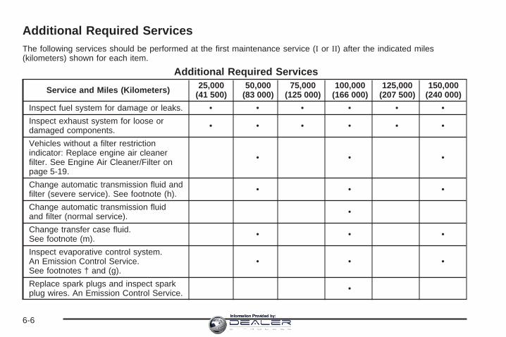
Additional Required ServicesThe following services should be performed at the first maintenance service (I or II) after the indicated miles(kilometers) shown for each item.
Additional Required Services
Service and Miles (Kilometers) 25,000(41 500)
50,000(83 000)
75,000(125 000)
100,000(166 000)
125,000(207 500)
150,000(240 000)
Inspect fuel system for damage or leaks. • • • • • •Inspect exhaust system for loose ordamaged components. • • • • • •
Vehicles without a filter restrictionindicator: Replace engine air cleanerfilter. See Engine Air Cleaner/Filter onpage 5-19.
• • •
Change automatic transmission fluid andfilter (severe service). See footnote (h). • • •
Change automatic transmission fluidand filter (normal service). •
Change transfer case fluid.See footnote (m). • • •
Inspect evaporative control system.An Emission Control Service.See footnotes † and (g).
• • •
Replace spark plugs and inspect sparkplug wires. An Emission Control Service. •
6-6Information Provided by:
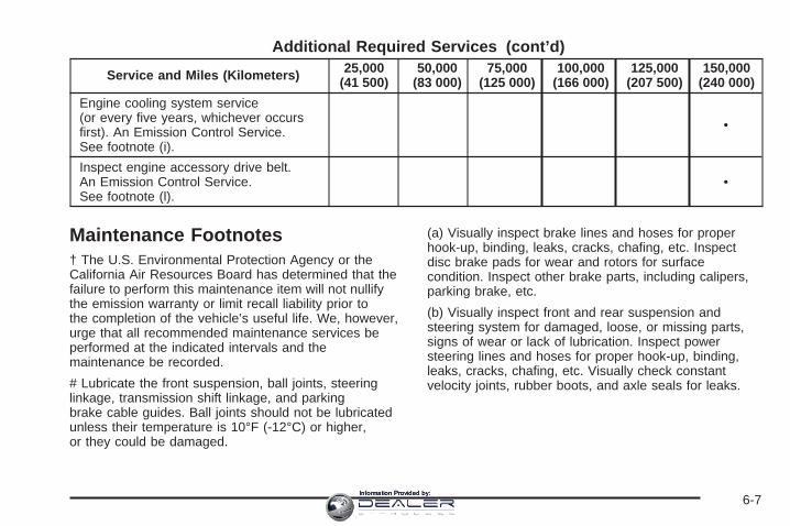
Additional Required Services (cont’d)
Service and Miles (Kilometers) 25,000(41 500)
50,000(83 000)
75,000(125 000)
100,000(166 000)
125,000(207 500)
150,000(240 000)
Engine cooling system service(or every five years, whichever occursfirst). An Emission Control Service.See footnote (i).
•
Inspect engine accessory drive belt.An Emission Control Service.See footnote (l).
•
Maintenance Footnotes† The U.S. Environmental Protection Agency or theCalifornia Air Resources Board has determined that thefailure to perform this maintenance item will not nullifythe emission warranty or limit recall liability prior tothe completion of the vehicle’s useful life. We, however,urge that all recommended maintenance services beperformed at the indicated intervals and themaintenance be recorded.
# Lubricate the front suspension, ball joints, steeringlinkage, transmission shift linkage, and parkingbrake cable guides. Ball joints should not be lubricatedunless their temperature is 10°F (-12°C) or higher,or they could be damaged.
(a) Visually inspect brake lines and hoses for properhook-up, binding, leaks, cracks, chafing, etc. Inspectdisc brake pads for wear and rotors for surfacecondition. Inspect other brake parts, including calipers,parking brake, etc.
(b) Visually inspect front and rear suspension andsteering system for damaged, loose, or missing parts,signs of wear or lack of lubrication. Inspect powersteering lines and hoses for proper hook-up, binding,leaks, cracks, chafing, etc. Visually check constantvelocity joints, rubber boots, and axle seals for leaks.
6-7Information Provided by:

(c) Visually inspect hoses and have them replaced ifthey are cracked, swollen, or deteriorated. Inspectall pipes, fittings, and clamps; replace with genuineGM parts as needed. To help ensure proper operation,a pressure test of the cooling system and pressurecap and cleaning the outside of the radiator andair conditioning condenser is recommended at leastonce a year.
(d) Visually inspect wiper blades for wear or cracking.Replace wiper blades that appear worn or damagedor that streak or miss areas of the windshield.
(e) Make sure the safety belt reminder light and all yourbelts, buckles, latch plates, retractors, and anchoragesare working properly. Look for any other loose ordamaged safety belt system parts. If you see anythingthat might keep a safety belt system from doing itsjob, have it repaired. Have any torn or frayed safety beltsreplaced. Also look for any opened or broken airbagcoverings, and have them repaired or replaced.The airbag system does not need regular maintenance.
(f) Lubricate all key lock cylinders, hood latchassembly, secondary latch, pivots, spring anchor,release pawl, rear compartment hinges, outer tailgatehandle pivot points, latch bolt, fuel door hinge, andfolding seat hardware. More frequent lubrication may berequired when exposed to a corrosive environment.Applying silicone grease on weatherstrips with a cleancloth will make them last longer, seal better, andnot stick or squeak.
(g) Inspect system. Check all fuel and vapor lines andhoses for proper hook-up, routing, and condition.Check that the purge valve works properly, if equipped.Replace as needed.
(h) Change automatic transmission fluid and filter if thevehicle is mainly driven under one or more of theseconditions:
− In heavy city traffic where the outside temperatureregularly reaches 90°F (32°C) or higher.
− In hilly or mountainous terrain.− When doing frequent trailer towing.− Uses such as found in taxi, police, or delivery
service.
(i) Drain, flush, and refill cooling system. This servicecan be complex; you should have your dealer performthis service. See Engine Coolant on page 5-24 forwhat to use. Inspect hoses. Clean radiator, condenser,pressure cap, and filler neck. Pressure test thecooling system and pressure cap.(j) A fluid loss in any vehicle system could indicate aproblem. Have the system inspected and repaired andthe fluid level checked. Add fluid if needed.(k) If you drive regularly under dusty conditions, inspectthe filter at each engine oil change.
(l) Visually inspect belt for fraying, excessive cracks, orobvious damage. Replace belt if necessary.(m) Check vent hose at transfer case for kinks andproper installation.
6-8Information Provided by:
Owner Checks and ServicesThese owner checks and services should be performedat the intervals specified to help ensure the safety,dependability, and emission control performance of yourvehicle. Your GM Goodwrench® dealer can assist youwith these checks and services.
Be sure any necessary repairs are completed at once.Whenever any fluids or lubricants are added to yourvehicle, make sure they are the proper ones, as shownin Recommended Fluids and Lubricants on page 6-12.
At Each Fuel FillIt is important to perform these underhood checks ateach fuel fill.
Engine Oil Level CheckCheck the engine oil level and add the proper oil ifnecessary. See Engine Oil on page 5-14 for furtherdetails.
Notice: It is important to check your oil regularlyand keep it at the proper level. Failure to keep yourengine oil at the proper level can cause damageto your engine not covered by your warranty.
Engine Coolant Level CheckCheck the engine coolant level and add DEX-COOL®
coolant mixture if necessary. See Engine Coolanton page 5-24 for further details.
Windshield Washer Fluid Level CheckCheck the windshield washer fluid level in the windshieldwasher fluid reservoir and add the proper fluid ifnecessary.
At Least Once a Month
Tire Inflation CheckVisually inspect your vehicle’s tires and make sure theyare inflated to the correct pressures. Do not forget tocheck the spare tire. See Tires on page 5-60 for furtherdetails. Check to make sure the spare tire is storedsecurely. See Changing a Flat Tire on page 5-81.
Tire Wear InspectionTire rotation may be required for high mileage highwaydrivers prior to the Engine Oil Life System servicenotification. Check the tires for wear and, if necessary,rotate the tires. See Tire Inspection and Rotation onpage 5-72.
6-9Information Provided by:
At Least Once a Year
Starter Switch Check
{CAUTION:
When you are doing this inspection, thevehicle could move suddenly. If the vehiclemoves, you or others could be injured.
1. Before you start, be sure you have enough roomaround the vehicle.
2. Firmly apply both the parking brake and the regularbrake. See Parking Brake on page 2-33.Do not use the accelerator pedal, and be ready toturn off the engine immediately if it starts.
3. Try to start the engine in each gear. The vehicleshould start only in PARK (P) or NEUTRAL (N).If the vehicle starts in any other position, contactyour GM Goodwrench® dealer for service.
Automatic Transmission Shift LockControl System Check
{CAUTION:
When you are doing this inspection, thevehicle could move suddenly. If the vehiclemoves, you or others could be injured.
1. Before you start, be sure you have enough roomaround the vehicle. It should be parked on a levelsurface.
2. Firmly apply the parking brake. See Parking Brakeon page 2-33.Be ready to apply the regular brake immediately ifthe vehicle begins to move.
3. With the engine off, turn the ignition to RUN, but donot start the engine. Without applying the regularbrake, try to move the shift lever out of PARK (P)with normal effort. If the shift lever moves outof PARK (P), contact your GM Goodwrench® dealerfor service.
6-10Information Provided by:

Ignition Transmission Lock CheckWhile parked, and with the parking brake set, try to turnthe ignition to LOCK in each shift lever position.
• The ignition should turn to LOCK only when theshift lever is in PARK (P).
• The key should come out only in LOCK.
Contact your GM Goodwrench® dealer if service isrequired.
Parking Brake and AutomaticTransmission Park (P) Mechanism Check
{CAUTION:
When you are doing this check, your vehiclecould begin to move. You or others could beinjured and property could be damaged.Make sure there is room in front of yourvehicle in case it begins to roll. Be ready toapply the regular brake at once should thevehicle begin to move.
Park on a fairly steep hill, with the vehicle facingdownhill. Keeping your foot on the regular brake,set the parking brake.
• To check the parking brake’s holding ability:With the engine running and transmission inNEUTRAL (N), slowly remove foot pressure fromthe regular brake pedal. Do this until the vehicle isheld by the parking brake only.
• To check the PARK (P) mechanism’s holding ability:With the engine running, shift to PARK (P).Then release the parking brake followed by theregular brake.
Contact your GM Goodwrench® dealer if service isrequired.
Underbody Flushing ServiceAt least every spring, use plain water to flush anycorrosive materials from the underbody. Take careto clean thoroughly any areas where mud and otherdebris can collect.
6-11Information Provided by:

Recommended Fluids andLubricantsFluids and lubricants identified below by name, partnumber, or specification may be obtained fromyour dealer.
Usage Fluid/Lubricant
Engine Oil
Engine oil which meetsGM Standard GM6094M anddisplays the American PetroleumInstitute Certified for GasolineEngines starburst symbol.GM Goodwrench® oil meets allthe requirements for your vehicle.To determine the proper viscosityfor your vehicle’s engine,see Engine Oil on page 5-14.
Engine Coolant
50/50 mixture of clean, drinkablewater and use only DEX-COOL®
Coolant. See Engine Coolant onpage 5-24.
Usage Fluid/Lubricant
Hydraulic BrakeSystem
Delco® Supreme 11 Brake Fluid orequivalent DOT-3 brake fluid.
WindshieldWasher GM Optikleen® Washer Solvent.
Power SteeringSystem
GM Power Steering Fluid(GM Part No. U.S. 89021184,in Canada 89021186).
AutomaticTransmission
DEXRON®-VI AutomaticTransmission Fluid.
Key LockCylinders
Multi-Purpose Lubricant, Superlube(GM Part No. U.S. 12346241,in Canada 10953474).
ChassisLubrication
Chassis Lubricant(GM Part No. U.S. 12377985,in Canada 88901242) or lubricantmeeting requirements of NLGI #2,Category LB or GC-LB.
6-12Information Provided by:

Usage Fluid/Lubricant
Front andRear Axle
SAE 75W-90 SyntheticAxle Lubricant(GM Part No. U.S. 12378261,in Canada 10953455) meetingGM Specification 9986115.
Transfer Case
DEXRON®-III AutomaticTransmission Fluid. Look for“Approved for the H-Specification”on the label.
Front AxlePropshaft
Spline
Spline Lubricant, Special Lubricant(GM Part No. U.S. 12345879,in Canada 10953511) orlubricant meeting requirementsof GM 9985830.
Usage Fluid/Lubricant
Hood HingesMulti-Purpose Lubricant, Superlube(GM Part No. U.S. 12346241,in Canada 10953474).
Outer TailgateHandle Pivot
Points
Multi-Purpose Lubricant, Superlube(GM Part No. U.S. 12346241,in Canada 10953474).
WeatherstripConditioning
Dielectric Silicone Grease(GM Part No. U.S. 12345579,in Canada 992887).
WeatherstripSqueaks
Synthetic Grease withTeflon, Superlube(GM Part No. U.S. 12371287,in Canada 10953437).
6-13Information Provided by:

Normal Maintenance Replacement PartsReplacement parts listed below by name, part number or specification can be obtained from your GM dealer.
Part GM Part Number ACDelco ® Part NumberEngine Air Cleaner/Filter 10368768 A1518COil Filter 88984215 PF46Spark Plugs 12571164 41-985Windshield Wiper Blades
22.0 inches (56.0 cm) 15153642 —
Engine Drive Belt Routing
(A) Air Conditioning Compressor
6-14Information Provided by:

Maintenance RecordAfter the scheduled services are performed, record the date, odometer reading, who performed the service, and thetype of services performed in the boxes provided. See Maintenance Requirements on page 6-2. Any additionalinformation from Owner Checks and Services on page 6-9 can be added on the following record pages. You shouldretain all maintenance receipts.
Maintenance Record
Date OdometerReading Serviced By Maintenance I or
Maintenance II Services Performed
6-15Information Provided by:

Maintenance Record (cont’d)
Date OdometerReading Serviced By Maintenance I or
Maintenance II Services Performed
6-16Information Provided by:
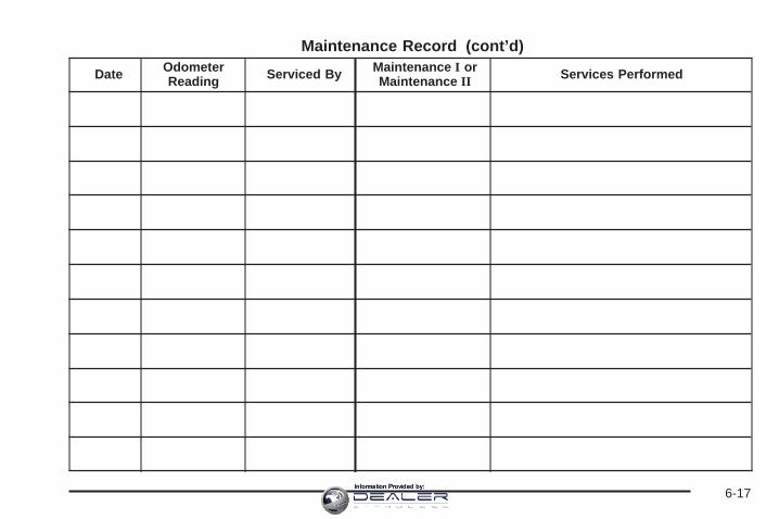
Maintenance Record (cont’d)
Date OdometerReading Serviced By Maintenance I or
Maintenance II Services Performed
6-17Information Provided by:

Maintenance Record (cont’d)
Date OdometerReading Serviced By Maintenance I or
Maintenance II Services Performed
6-18Information Provided by:
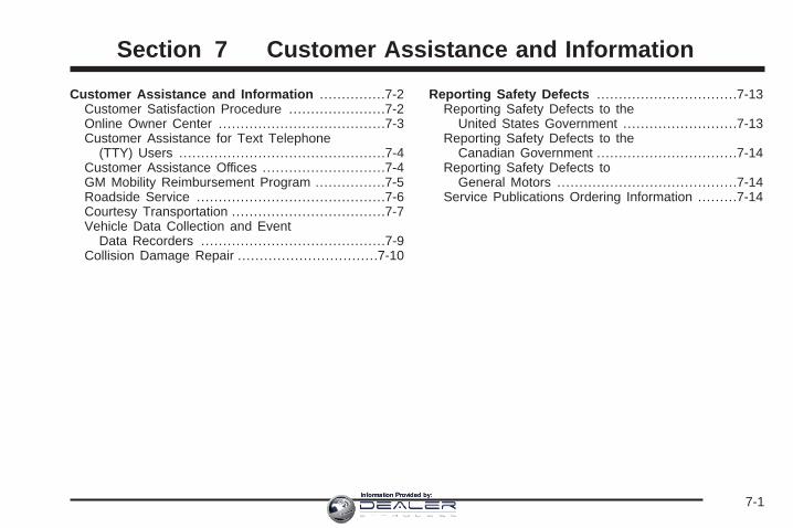
Customer Assistance and Information ...............7-2Customer Satisfaction Procedure ......................7-2Online Owner Center ......................................7-3Customer Assistance for Text Telephone
(TTY) Users ...............................................7-4Customer Assistance Offices ............................7-4GM Mobility Reimbursement Program ................7-5Roadside Service ...........................................7-6Courtesy Transportation ...................................7-7Vehicle Data Collection and Event
Data Recorders ..........................................7-9Collision Damage Repair ................................7-10
Reporting Safety Defects ................................7-13Reporting Safety Defects to the
United States Government ..........................7-13Reporting Safety Defects to the
Canadian Government ................................7-14Reporting Safety Defects to
General Motors .........................................7-14Service Publications Ordering Information .........7-14
Section 7 Customer Assistance and Information
7-1Information Provided by:
Customer Assistance andInformation
Customer Satisfaction ProcedureYour satisfaction and goodwill are important toyour dealer and to Cadillac. Normally, any concernswith the sales transaction or the operation of yourvehicle will be resolved by your dealer’s sales or servicedepartments. Sometimes, however, despite the bestintentions of all concerned, misunderstandings canoccur. If your concern has not been resolved to yoursatisfaction, the following steps should be taken:
STEP ONE: Discuss your concern with a member ofdealership management. Normally, concerns canbe quickly resolved at that level. If the matter hasalready been reviewed with the sales, service or partsmanager, contact the owner of the dealership orthe general manager.
STEP TWO: If after contacting a member of dealershipmanagement, it appears your concern cannot beresolved by the dealership without further help, contactthe Cadillac Customer Assistance Center, 24 hoursa day, by calling 1-800-458-8006. In Canada, contactthe Canadian Cadillac Customer Communication Centreby calling 1-888-446-2000.
We encourage you to call the toll-free number in orderto give your inquiry prompt attention. Please havethe following information available to give the CustomerAssistance Representative:
• Vehicle Identification Number (VIN). This isavailable from the vehicle registration or title, or theplate at the top left of the instrument panel andvisible through the windshield.
• Dealership name and location.
• Vehicle delivery date and present mileage.
When contacting Cadillac, please remember that yourconcern will likely be resolved at a dealer’s facility.That is why we suggest you follow Step One first if youhave a concern.
STEP THREE: Both General Motors and your dealerare committed to making sure you are completelysatisfied with your new vehicle. However, if you continueto remain unsatisfied after following the procedureoutlined in Steps One and Two, you should file with theBBB Auto Line Program to enforce any additionalrights you may have. Canadian owners refer to yourWarranty and Owner Assistance Information booklet forinformation on the Canadian Motor Vehicle ArbitrationPlan (CAMVAP).
7-2Information Provided by:

The BBB Auto Line Program is an out of court programadministered by the Council of Better BusinessBureaus to settle automotive disputes regarding vehiclerepairs or the interpretation of the New VehicleLimited Warranty. Although you may be required toresort to this informal dispute resolution program prior tofiling a court action, use of the program is free ofcharge and your case will generally be heard within40 days. If you do not agree with the decision given inyour case, you may reject it and proceed with any othervenue for relief available to you.
You may contact the BBB Auto Line Program using thetoll-free telephone number or write them at thefollowing address:
BBB Auto Line ProgramCouncil of Better Business Bureaus, Inc.4200 Wilson BoulevardSuite 800Arlington, VA 22203-1838
Telephone: 1-800-955-5100
This program is available in all 50 states and theDistrict of Columbia. Eligibility is limited by vehicle age,mileage and other factors. General Motors reservesthe right to change eligibility limitations and/ordiscontinue its participation in this program.
Online Owner CenterThe Owner Center is a resource for your GM ownershipneeds. Specific vehicle information can be found inone place.
The Online Owner Center allows you to:
• Get e-mail service reminders.
• Access information about your specific vehicle,including tips and videos and an electronicversion of this owner’s manual (United States only).
• Keep track of your vehicle’s service history andmaintenance schedule.
• Find GM dealers for service nationwide.
• Receive special promotions and privileges onlyavailable to members (United States only).
Refer to the web for updated information.
To register your vehicle, visit www.MyGMLink.com(United States) or My GM Canada withinwww.gmcanada.com (Canada).
7-3Information Provided by:

Customer Assistance for TextTelephone (TTY) UsersTo assist customers who are deaf, hard of hearing, orspeech-impaired and who use Text Telephones (TTYs),Cadillac has TTY equipment available at its CustomerAssistance Center. Any TTY user can communicatewith Cadillac by dialing: 1-800-833-CMCC (2622).(TTY users in Canada can dial 1-800-263-3830.)
Customer Assistance OfficesCadillac encourages customers to call the toll-freenumber for assistance. However, if a customer wishesto write or e-mail Cadillac, refer to the addresses below.
United States — Customer AssistanceCadillac Customer Assistance CenterCadillac Motor Car DivisionP.O. Box 33169Detroit, MI 48232-5169
www.Cadillac.com1-800-458-80061-800-833-2622 (For Text Telephone devices (TTYs))Roadside Assistance: 1-800-882-1112Fax Number: 313-381-0022
From Puerto Rico:1-800-496-9992 (English)1-800-496-9993 (Spanish)Fax Number: 313-381-0022
From U.S. Virgin Islands:1-800-496-9994Fax Number: 313-381-0022
Canada — Customer AssistanceGeneral Motors of Canada LimitedCanadian Cadillac Customer CommunicationCentre, 163-0051908 Colonel Sam DriveOshawa, Ontario L1H 8P7
1-888-446-20001-800-263-3830 (For Text Telephone devices (TTYs))Roadside Assistance: 1-800-882-1112
7-4Information Provided by:

Overseas — Customer AssistancePlease contact the local General Motors Business Unit.
Mexico, Central America andCaribbean Islands/Countries(Except Puerto Rico and U.S. VirginIslands) — Customer Assistance
General Motors de Mexico, S. de R.L. de C.V.Customer Assistance CenterPaseo de la Reforma # 2740Col. Lomas de BezaresC.P. 11910, Mexico, D.F.01-800-508-0000Long Distance: 011-52-53 29 0 800
GM Mobility ReimbursementProgram
This program, available to qualified applicants, canreimburse you up to $1,000 of the cost of eligibleaftermarket adaptive equipment required for your vehicle,such as hand controls or a wheelchair/scooter lift.
The offer is available for a very limited period of timefrom the date of vehicle purchase/lease. For moredetails, or to determine your vehicle’s eligibility, visitgmmobility.com or call the GM Mobility AssistanceCenter at 1-800-323-9935. Text telephone (TTY) users,call 1-800-833-9935.
GM of Canada also has a Mobility Program.Call 1-800-GM-DRIVE (463-7483) for details.TTY users call 1-800-263-3830.
7-5Information Provided by:

Roadside ServiceCadillac’s exceptional Roadside Service is more than anauto club or towing service. It provides every Cadillacowner with the advantage of contacting a Cadillacadvisor and, where available, a Cadillac trained dealertechnician who can provide on-site service.
Each technician travels with a specially equippedservice vehicle complete with the necessary Cadillacparts and tools required to handle most roadside repairs.
Cadillac Roadside Service® can be reached by dialing1-800-882-1112, 24 hours a day, 365 days a year.This service is provided at no charge for any situationcovered by the base warranty coverage and at anominal charge if the Cadillac is no longer covered bythe base warranty. Roadside Service is available only inthe United States and Canada.
Cadillac Owner Privileges™Roadside Service provides several Cadillac OwnerPrivileges™ at “no charge,” throughout your CadillacWarranty Period — 48 months/50,000 miles (80 000 km).
Emergency Road Service is performed on site for thefollowing situations:
• Towing Service
• Battery Jump Starting
• Lock Out Assistance
• Fuel Delivery
• Flat Tire Change (Covers change only)
• Trip Interruption — If your trip is interrupted due toa warranty failure, incidental expenses may bereimbursed during the 48 months/50,000 miles(80 000 km) warranty period. Items coveredare hotel, meals, and rental car.
7-6Information Provided by:

Roadside Service AvailabilityWherever you drive in the United States or Canada,an advisor is available to assist you over the phone.A dealer technician, if available, can travel to yourlocation within a 30 mile (50 km) radius of a participatingCadillac dealership. If beyond this radius, we willarrange to have your car towed to the nearest Cadillacdealership.
Reaching Roadside ServiceDial the toll-free Roadside Service number:1-800-882-1112. A Roadside Service Advisor will assistyou and request the following information:
• A description of the problem
• Name, home address, home telephone number
• Location of your Cadillac and number you arecalling from
• The model year, Vehicle Identification Number(VIN), mileage, and date of delivery
Roadside Service for the Hearing orSpeech ImpairedRoadside Service is prepared to assist owners who havehearing difficulties or are speech impaired. Cadillac hasinstalled special telecommunication devices calledText Telephone (TTY) in the Roadside Service Center.
Any customer who has access to a (TTY) or aconventional teletypewriter can communicate withCadillac by dialing from the United States or Canada1-888-889-2438 — daily, 24 hours.
Courtesy TransportationTo enhance your ownership experience, we and ourparticipating dealers are proud to offer CourtesyTransportation, a customer support program fornew vehicles.
The Courtesy Transportation program is offered tocustomers in conjunction with the Bumper-to-Bumpercoverage provided by the New Vehicle Limited Warranty.Several transportation options are available whenwarranty repairs are required. This will reduce yourinconvenience during warranty repairs.
7-7Information Provided by:
Scheduling Service AppointmentsWhen your vehicle requires warranty service, you shouldcontact your dealer and request an appointment.By scheduling a service appointment and advising yourservice consultant of your transportation needs, yourdealer can help minimize your inconvenience.
If your vehicle cannot be scheduled into the servicedepartment immediately, keep driving it until it can bescheduled for service, unless, of course, the problemis safety-related. If it is, please call your dealership,let them know this, and ask for instructions.
If the dealer requests that you simply drop the vehicle offfor service, you are urged to do so as early in the workday as possible to allow for the same day repair.
Transportation OptionsWarranty service can generally be completed while youwait. However, if you are unable to wait, GM helpsto minimize your inconvenience by providing severaltransportation options. Depending on the circumstances,your dealer can offer you one of the following:
Shuttle ServiceParticipating dealers can provide you with shuttleservice to get you to your destination with minimalinterruption of your daily schedule. This includesone-way or round trip shuttle service to a destinationup to 10 miles (16 km) from the dealership.
Public Transportation or FuelReimbursementIf your vehicle requires warranty repairs, reimbursementof public transportation expenses may be available,for up to a maximum of five days. In addition, should youarrange transportation through a friend or relative,reimbursement for reasonable fuel expenses may beavailable, up to a five-day maximum. Claim amountsshould reflect actual costs and be supported by originalreceipts.
Courtesy Rental VehicleYour dealer may arrange to provide you with a courtesyrental vehicle or reimburse you for a rental vehiclethat you obtain if your vehicle is kept for a warrantyrepair. Reimbursement will be limited to a maximumamount per day and must be supported by receipts. Thisrequires that you sign and complete a rental agreementand meet state, local and rental vehicle providerrequirements. Requirements vary and may includeminimum age requirements, insurance coverage, creditcard, etc. You are responsible for fuel usage chargesand may also be responsible for taxes, levies,usage fees, excessive mileage or rental usage beyondthe completion of the repair.
Generally it is not possible to provide a like-vehicle as acourtesy rental.
7-8Information Provided by:

Additional Program InformationCourtesy Transportation is available during theBumper-to-Bumper warranty coverage period,but it is not part of the New Vehicle Limited Warranty.A separate booklet entitled Warranty and OwnerAssistance Information furnished with each new vehicleprovides detailed warranty coverage information.
Courtesy Transportation is available only at participatingdealers and all program options, such as shuttle service,may not be available at every dealer. Please contactyour dealer for specific information about availability.All Courtesy Transportation arrangements will beadministered by appropriate dealer personnel.
Canadian Vehicles: For warranty repairs during theComplete Vehicle Coverage period of theGeneral Motors of Canada New Vehicle LimitedWarranty, alternative transportation may be availableunder the Courtesy Transportation Program.Please consult your dealer for details.
General Motors reserves the right to unilaterally modify,change or discontinue Courtesy Transportation atany time and to resolve all questions of claim eligibilitypursuant to the terms and conditions describedherein at its sole discretion.
Vehicle Data Collection andEvent Data RecordersYour vehicle, like other modern motor vehicles, has anumber of sophisticated computer systems thatmonitor and control several aspects of the vehicle’sperformance. Your vehicle uses on-board vehiclecomputers to monitor emission control components tooptimize fuel economy, to monitor conditions for airbagdeployment and, if so equipped, to provide anti-lockbraking and to help the driver control the vehicle indifficult driving situations. Some information may bestored during regular operations to facilitate repair ofdetected malfunctions; other information is stored only ina crash event by computer systems, such as thosecommonly called event data recorders (EDR).In a crash event, computer systems, such as theAirbag Sensing and Diagnostic Module (SDM) in yourvehicle may record information about the condition of thevehicle and how it was operated, such as data relatedto engine speed, brake application, throttle position,vehicle speed, safety belt usage, airbag readiness,airbag performance, and the severity of a collision.If your vehicle is equipped with StabiliTrak®, steeringperformance, including yaw rate, steering wheelangle, and lateral acceleration, is also recorded.This information has been used to improve vehiclecrash performance and may be used to improve crashperformance of future vehicles and driving safety.
7-9Information Provided by:
Unlike the data recorders on many airplanes, theseon-board systems do not record sounds, such asconversation of vehicle occupants.
To read this information, special equipment is neededand access to the vehicle or the device that storesthe data is required. GM will not access informationabout a crash event or share it with others other than:
• with the consent of the vehicle owner or, if thevehicle is leased, with the consent of the lessee,
• in response to an official request of police or similargovernment office,
• as part of GM’s defense of litigation through thediscovery process, or
• as required by law.
In addition, once GM collects or receives data, GM may:
• use the data for GM research needs,
• make it available for research where appropriateconfidentiality is to be maintained and need isshown, or
• share summary data which is not tied to a specificvehicle with non-GM organizations for researchpurposes.
Others, such as law enforcement, may have access tothe special equipment that can read the informationif they have access to the vehicle or the devicethat stores the data.
If your vehicle is equipped with OnStar®, please checkthe OnStar® subscription service agreement ormanual for information on its operations and datacollection.
Collision Damage RepairIf your vehicle is involved in a collision and it is damaged,have the damage repaired by a qualified technician usingthe proper equipment and quality replacement parts.Poorly performed collision repairs will diminish yourvehicle’s resale value, and safety performance can becompromised in subsequent collisions.
Collision PartsGenuine GM Collision parts are new parts made withthe same materials and construction methods asthe parts with which your vehicle was originally built.Genuine GM Collision parts are your best choiceto assure that your vehicle’s designed appearance,durability and safety are preserved. The use of GenuineGM parts can help maintain your GM New VehicleWarranty.
7-10Information Provided by:
Recycled original equipment parts may also be used forrepair. These parts are typically removed from vehiclesthat were total losses in prior accidents. In mostcases, the parts being recycled are from undamagedsections of the vehicle. A recycled original equipmentGM part, may be an acceptable choice to maintain yourvehicle’s originally designed appearance and safetyperformance, however, the history of these parts is notknown. Such parts are not covered by your GM NewVehicle Limited Warranty, and any related failuresare not covered by that warranty.
Aftermarket collision parts are also available. These aremade by companies other than GM and may not havebeen tested for your vehicle. As a result, these parts mayfit poorly, exhibit premature durability/corrosion problems,and may not perform properly in subsequent collisions.Aftermarket parts are not covered by your GM NewVehicle Limited Warranty, and any vehicle failure relatedto such parts are not covered by that warranty.
Repair FacilityGM also recommends that you choose a collision repairfacility that meets your needs before you ever needcollision repairs. Your GM dealer may have a collisionrepair center with GM-trained technicians and stateof the art equipment, or be able to recommend acollision repair center that has GM-trained techniciansand comparable equipment.
Insuring Your VehicleProtect your investment in your GM vehicle withcomprehensive and collision insurance coverage.There are significant differences in the quality ofcoverage afforded by various insurance policy terms.Many insurance policies provide reduced protectionto your GM vehicle by limiting compensation fordamage repairs by using aftermarket collision parts.Some insurance companies will not specify aftermarketcollision parts. When purchasing insurance, werecommend that you assure your vehicle will be repairedwith GM original equipment collision parts. If suchinsurance coverage is not available from your currentinsurance carrier, consider switching to anotherinsurance carrier.
If your vehicle is leased, the leasing company mayrequire you to have insurance that assures repairs withGenuine GM Original Equipment Manufacturer (OEM)parts or Genuine Manufacturer replacement parts.Read your lease carefully, as you may be charged atthe end of your lease for poor quality repairs.
7-11Information Provided by:
If an Accident OccursHere is what to do if you are involved in an accident.
• Try to relax and then check to make sure you are allright. If you are uninjured, make sure that no one elsein your vehicle, or the other vehicle, is injured.
• If there has been an injury, call 911 for help. Do notleave the scene of an accident until all matters havebeen taken care of. Move your vehicle only if itsposition puts you in danger or you are instructed tomove it by a police officer.
• Give only the necessary and requested informationto police and other parties involved in the accident.Do not discuss your personal condition, mental frameof mind, or anything unrelated to the accident. Thiswill help guard against post-accident legal action.
• If you need roadside assistance, call GM RoadsideAssistance. See Roadside Service on page 7-6 formore information.
• If your vehicle cannot be driven, know where thetowing service will be taking it. Get a card from thetow truck operator or write down the driver’s name,the service’s name, and the phone number.
• Remove any valuables from your vehicle before it istowed away. Make sure this includes your insuranceinformation and registration if you keep these itemsin your vehicle.
• Gather the important information you will need fromthe other driver. Things like name, address, phonenumber, driver’s license number, vehicle licenseplate, vehicle make, model and model year, VehicleIdentification Number (VIN), insurance company andpolicy number, and a general description of thedamage to the other vehicle.
• If possible, call your insurance company from thescene of the accident. They will walk you throughthe information they will need. If they ask for apolice report, phone or go to the police departmentheadquarters the next day and you can get a copy ofthe report for a nominal fee. In some states with“no fault” insurance laws, a report may not benecessary. This is especially true if there are noinjuries and both vehicles are driveable.
• Choose a reputable collision repair facility for yourvehicle. Whether you select a GM dealer or a privatecollision repair facility to fix the damage, make sureyou are comfortable with them. Remember, you willhave to feel comfortable with their work for along time.
• Once you have an estimate, read it carefully andmake sure you understand what work will beperformed on your vehicle. If you have a question,ask for an explanation. Reputable shops welcomethis opportunity.
7-12Information Provided by:

Managing the Vehicle DamageRepair ProcessIn the event that your vehicle requires damage repairs,GM recommends that you take an active role in itsrepair. If you have a pre-determined repair facility ofchoice, take your vehicle there, or have it towed there.Specify to the facility that any required replacementcollision parts be original equipment parts, either newGenuine GM parts or recycled original GM parts.Remember, recycled parts will not be covered byyour GM vehicle warranty.
Insurance pays the bill for the repair, but you mustlive with the repair. Depending on your policy limits,your insurance company may initially value the repairusing aftermarket parts. Discuss this with your repairprofessional, and insist on Genuine GM parts.Remember if your vehicle is leased you may beobligated to have the vehicle repaired with GenuineGM parts, even if your insurance coverage does not paythe full cost.
If another party’s insurance company is paying for therepairs, you are not obligated to accept a repairvaluation based on that insurance company’s collisionpolicy repair limits, as you have no contractual limits withthat company. In such cases, you can have control ofthe repair and parts choices as long as cost stays withinreasonable limits.
Reporting Safety Defects
Reporting Safety Defects to theUnited States GovernmentIf you believe that your vehicle has a defect which couldcause a crash or could cause injury or death, youshould immediately inform the National Highway TrafficSafety Administration (NHTSA), in addition to notifyingGeneral Motors.
If NHTSA receives similar complaints, it may open aninvestigation, and if it finds that a safety defect exists ina group of vehicles, it may order a recall and remedycampaign. However, NHTSA cannot become involvedin individual problems between you, your dealer, orGeneral Motors.
To contact NHTSA, you may either call the Auto SafetyHotline toll-free at 1-800-424-9393 (or 366-0123 inthe Washington, D.C. area) or write to:
NHTSA, U.S. Department of TransportationWashington, D.C. 20590
You can also obtain other information about motorvehicle safety from the hotline.
7-13Information Provided by:

Reporting Safety Defects to theCanadian GovernmentIf you live in Canada, and you believe that your vehiclehas a safety defect, you should immediately notifyTransport Canada, in addition to notifying GeneralMotors of Canada Limited. You may call them at1-800-333-0510 or write to:
Transport CanadaPlace de Ville Tower C330 Sparks StreetOttawa, Ontario K1A 0N5
Reporting Safety Defects toGeneral MotorsIn addition to notifying NHTSA (or Transport Canada) ina situation like this, we certainly hope you will notifyus. Please call us at 1-800-458-8006, or write:
Cadillac Customer Assistance CenterCadillac Motor Car DivisionP.O. Box 33169Detroit, MI 48232-5169
In Canada, please call us at 1-888-446-2000. Or, write:Canadian Cadillac Customer CommunicationCentre, 163-005General Motors of Canada Limited1908 Colonel Sam DriveOshawa, Ontario L1H 8P7
Service Publications OrderingInformation
Service ManualsService Manuals have the diagnosis and repairinformation on engines, transmission, axle suspension,brakes, electrical, steering, body, etc.
Transmission, Transaxle, TransferCase Unit Repair ManualThis manual provides information on unit repair serviceprocedures, adjustments, and specifications forGM transmissions, transaxles, and transfer cases.
Service BulletinsService Bulletins give technical service informationneeded to knowledgeably service General Motors carsand trucks. Each bulletin contains instructions toassist in the diagnosis and service of your vehicle.
In Canada, information pertaining to Product ServiceBulletins can be obtained by contacting your GeneralMotors dealer or by calling 1-800-GM-DRIVE(1-800-463-7483).
7-14Information Provided by:
Owner’s InformationOwner publications are written specifically for ownersand intended to provide basic operational informationabout the vehicle. The owner’s manual will includethe Maintenance Schedule for all models.
In-Portfolio: Includes a Portfolio, Owner’s Manual, andWarranty Booklet.
RETAIL SELL PRICE: $35.00
Without Portfolio: Owner’s Manual only.
RETAIL SELL PRICE: $25.00
Current and Past Model Order FormsService Publications are available for current andpast model GM vehicles. To request an order form,please specify year and model name of the vehicle.
ORDER TOLL FREE: 1-800-551-4123Monday-Friday 8:00 AM - 6:00 PMEastern TimeFor Credit Card Orders Only(VISA-MasterCard-Discover), visit Helm, Inc. on theWorld Wide Web at: www.helminc.com
Or you can write to:
Helm, IncorporatedP.O. Box 07130Detroit, MI 48207
Prices are subject to change without notice and withoutincurring obligation. Allow ample time for delivery.
Note to Canadian Customers: All listed prices arequoted in U.S. funds. Canadian residents are to makechecks payable in U.S. funds.
7-15Information Provided by:

✍ NOTES
7-16Information Provided by:

AAccessories and Modifications ............................ 5-3Accessory Power Outlet(s) ............................... 3-21Adding Equipment to Your Airbag-Equipped
Vehicle ....................................................... 1-65Additives, Fuel ................................................. 5-6Add-On Electrical Equipment ........................... 5-109Adjustable Throttle and Brake Pedal .................. 2-28Air Cleaner/Filter, Engine ................................. 5-19Air Conditioning .............................................. 3-22Airbag
Passenger Status Indicator ........................... 3-32Readiness Light .......................................... 3-31
Airbag Sensing and Diagnostic Module (SDM) ......... 7-9Airbag System ................................................ 1-52
Adding Equipment to Your Airbag-EquippedVehicle ................................................... 1-65
How Does an Airbag Restrain? ...................... 1-58Passenger Sensing System ........................... 1-60Servicing Your Airbag-Equipped Vehicle .......... 1-64What Makes an Airbag Inflate? ...................... 1-58What Will You See After an Airbag Inflates? ........ 1-59When Should an Airbag Inflate? .................... 1-57Where Are the Airbags? ............................... 1-54
All-Wheel Drive ............................................... 5-45All-Wheel-Drive (AWD) System ......................... 4-12
Analog Clock .................................................. 3-22Antenna, Fixed Mast ...................................... 3-101Antenna, XM™ Satellite Radio
Antenna System ........................................ 3-102Anti-Lock Brake System (ABS) ........................... 4-7Anti-Lock Brake, System Warning Light .............. 3-36Appearance Care
Aluminum or Chrome-Plated Wheels ............. 5-105Care of Safety Belts ................................... 5-103Chemical Paint Spotting .............................. 5-106Cleaning Exterior Lamps/Lenses .................. 5-104Cleaning the Inside of Your Vehicle .............. 5-100Fabric/Carpet ............................................ 5-101Finish Care ............................................... 5-104Finish Damage .......................................... 5-106Instrument Panel, Vinyl, and Other Plastic
Surfaces ............................................... 5-102Leather .................................................... 5-102Sheet Metal Damage .................................. 5-106Speaker Covers ......................................... 5-103Tires ........................................................ 5-106Underbody Maintenance ............................. 5-106Vehicle Care/Appearance Materials ............... 5-107Washing Your Vehicle ................................. 5-103Weatherstrips ............................................ 5-103Windshield and Wiper Blades ...................... 5-105Wood Panels ............................................ 5-103
1Information Provided by:
Ashtray(s) ...................................................... 3-21Audio System(s) ............................................. 3-63
Audio Steering Wheel Controls ...................... 3-98Care of Your Cassette Tape Player ............... 3-100Care of Your CD and DVD Player ................ 3-101Care of Your CDs and DVDs ....................... 3-101CD Changer ............................................... 3-94Chime Level Adjustment ............................. 3-102Fixed Mast Antenna ................................... 3-101Navigation/Radio System, see Navigation
Manual ................................................... 3-80Radio with Cassette and CD ......................... 3-65Rear Seat Audio (RSA) ................................ 3-92Setting the Time .......................................... 3-64Theft-Deterrent Feature ................................ 3-97Understanding Radio Reception ..................... 3-99XM™ Satellite Radio Antenna System ........... 3-102
Automatic Headlamp System ............................ 3-15Automatic Transmission
Fluid .......................................................... 5-21Operation ................................................... 2-30
BBattery .......................................................... 5-39
Run-Down Protection ................................... 3-18Before Leaving on a Long Trip ......................... 4-35Brake
Anti-Lock Brake System (ABS) ........................ 4-7Emergencies ................................................ 4-8Parking ...................................................... 2-33System Warning Light .................................. 3-35
Brake Pedal, Throttle ....................................... 2-28Brakes .......................................................... 5-36Braking ........................................................... 4-6Braking in Emergencies ..................................... 4-8Break-In, New Vehicle ..................................... 2-25Bulb Replacement ........................................... 5-52
Front Turn Signal, Sidemarker andDaytime Running Lamps ........................... 5-56
Halogen Bulbs ............................................ 5-52Headlamp Aiming ........................................ 5-48Headlamps ................................................. 5-53High Intensity Discharge (HID) Lighting ........... 5-52Replacement Bulbs ...................................... 5-58Taillamps, Turn Signal, Stoplamps and
Back-up Lamps ........................................ 5-57Buying New Tires ........................................... 5-74
2Information Provided by:

CCalifornia Fuel .................................................. 5-6California Proposition 65 Warning ....................... 5-3Canadian Owners ................................................ iiCapacities and Specifications .......................... 5-119Carbon Monoxide ........... 2-11, 2-19, 2-36, 4-38, 4-50Care of
Safety Belts .............................................. 5-103Your Cassette Tape Player .......................... 3-100Your CD and DVD Player ........................... 3-101Your CDs and DVDs .................................. 3-101
Cargo Area, All-Weather .................................. 2-68Cargo Cover Panels ........................................ 2-55Cargo Lamp Light ........................................... 3-43CD Changer ................................................... 3-94Center Console Storage Area ........................... 2-53Chains, Tire ................................................... 5-79Charging System Light .................................... 3-34Check
Engine Light ............................................... 3-39Checking Things Under the Hood ...................... 5-10Chemical Paint Spotting ................................. 5-106Child Restraints
Child Restraint Systems ............................... 1-33Infants and Young Children ........................... 1-30Lower Anchors and Tethers for
Children .................................................. 1-39
Child Restraints (cont.)Older Children ............................................. 1-27Securing a Child Restraint in a
Rear Seat Position ................................... 1-46Securing a Child Restraint in the
Right Front Seat Position .......................... 1-48Where to Put the Restraint ........................... 1-38
Chime Level Adjustment ................................. 3-102Cigarette Lighter ............................................. 3-21Cleaning
Aluminum or Chrome-Plated Wheels ............. 5-105Exterior Lamps/Lenses ................................ 5-104Fabric/Carpet ............................................ 5-101Finish Care ............................................... 5-104Inside of Your Vehicle ................................. 5-100Instrument Panel, Vinyl, and Other Plastic
Surfaces ............................................... 5-102Leather .................................................... 5-102Speaker Covers ......................................... 5-103Tires ........................................................ 5-106Underbody Maintenance ............................. 5-106Washing Your Vehicle ................................. 5-103Weatherstrips ............................................ 5-103Windshield and Wiper Blades ...................... 5-105Wood Panels ............................................ 5-103
Climate Control SystemDual Automatic ............................................ 3-22Outlet Adjustment ........................................ 3-27
3Information Provided by:

Clock ............................................................ 3-22Collision Damage Repair .................................. 7-10Comfort Guides, Rear Safety Belt ..................... 1-25Content Theft-Deterrent .................................... 2-23Control of a Vehicle .......................................... 4-5Coolant
Engine Temperature Gage ............................ 3-37Heater, Engine ............................................ 2-28Surge Tank Pressure Cap ............................. 5-26
Cooling System .............................................. 5-28Cruise Control ................................................ 3-10Cruise Control Light ........................................ 3-43Cupholder(s) .................................................. 2-53Customer Assistance Information
Courtesy Transportation .................................. 7-7Customer Assistance for Text
Telephone (TTY) Users ............................... 7-4Customer Assistance Offices ........................... 7-4Customer Satisfaction Procedure ..................... 7-2GM Mobility Reimbursement Program ............... 7-5Reporting Safety Defects to
General Motors ........................................ 7-14Reporting Safety Defects to the
Canadian Government .............................. 7-14Reporting Safety Defects to the
United States Government ......................... 7-13Roadside Service .......................................... 7-6Service Publications Ordering Information ........ 7-14
DDaytime Running Lamps .................................. 3-15Defensive Driving ............................................. 4-2Delayed Locking ............................................... 2-9Doing Your Own Service Work ........................... 5-4Dome Lamp Override ...................................... 3-18Dome Lamps ................................................. 3-17Door
Delayed Locking ........................................... 2-9Locks .......................................................... 2-8Power Door Locks ......................................... 2-9Programmable Automatic Door Locks ............. 2-10Rear Door Security Locks ............................. 2-10
DriverPosition, Safety Belt ..................................... 1-14
Driver Information Center (DIC) ......................... 3-45DIC Operation and Displays .......................... 3-45DIC Vehicle Customization ............................ 3-57DIC Warnings and Messages ........................ 3-48
DrivingAt Night ..................................................... 4-30City ........................................................... 4-33Defensive ..................................................... 4-2Drunken ....................................................... 4-3Freeway ..................................................... 4-34Hill and Mountain Roads .............................. 4-36In Rain and on Wet Roads ........................... 4-31
4Information Provided by:

Driving (cont.)Off-Road .................................................... 4-17Recovery Hooks .......................................... 4-43Rocking Your Vehicle to Get it Out ................. 4-42Winter ........................................................ 4-38
Dual Automatic Climate Control System ............. 3-22DVD
Rear Seat Entertainment System ................... 3-80
EElectrical System
Add-On Equipment ..................................... 5-109Center Instrument Panel Fuse Block ............. 5-112Fuses and Circuit Breakers ......................... 5-109Instrument Panel Fuse Block ....................... 5-110Power Windows and Other Power Options .... 5-109Underhood Fuse Block ............................... 5-113Windshield Wiper Fuses ............................. 5-109
EngineAir Cleaner/Filter ......................................... 5-19Battery ....................................................... 5-39Check and Service Engine Soon Light ............ 3-39Coolant ...................................................... 5-24Coolant Heater ............................................ 2-28Coolant Temperature Gage ........................... 3-37Drive Belt Routing ....................................... 6-14Engine Compartment Overview ...................... 5-12
Engine (cont.)Exhaust ..................................................... 2-36Fan Noise .................................................. 5-33Oil ............................................................. 5-14Oil Life System ........................................... 5-17Overheated Protection Operating Mode ........... 5-28Overheating ................................................ 5-26Starting ...................................................... 2-27
Entry/Exit Lighting ........................................... 3-18Event Data Recorders (EDR) ............................. 7-9Extender, Safety Belt ....................................... 1-26Exterior Cargo Lamps ...................................... 3-17Exterior Lamps ............................................... 3-14
FFilter
Engine Air Cleaner ...................................... 5-19Finish Damage ............................................. 5-106Fixed Mast Antenna ....................................... 3-101Flash-to-Pass ................................................... 3-9Flat Tire ........................................................ 5-80Flat Tire, Changing ......................................... 5-81Flat Tire, Storing ............................................. 5-96Fluid
Automatic Transmission ................................ 5-21Power Steering ........................................... 5-34Windshield Washer ...................................... 5-35
5Information Provided by:
Fog Lamps .................................................... 3-16Front Axle ...................................................... 5-47Fuel ............................................................... 5-5
Additives ...................................................... 5-6California Fuel .............................................. 5-6Filling a Portable Fuel Container .................... 5-10Filling Your Tank ........................................... 5-8Fuels in Foreign Countries .............................. 5-7Gage ......................................................... 3-44Gasoline Octane ........................................... 5-5Gasoline Specifications .................................. 5-5Low Warning Light ....................................... 3-44
FusesCenter Instrument Panel Fuse Block ............. 5-112Fuses and Circuit Breakers ......................... 5-109Instrument Panel Fuse Block ....................... 5-110Underhood Fuse Block ............................... 5-113Windshield Wiper ....................................... 5-109
GGage
Engine Coolant Temperature ......................... 3-37Fuel .......................................................... 3-44Oil Pressure ............................................... 3-41Speedometer .............................................. 3-30
Gage (cont.)Tachometer ................................................. 3-30Transmission Temperature ............................. 3-38Voltmeter Gage ........................................... 3-34
Garage Door Opener ....................................... 2-48Gasoline
Octane ........................................................ 5-5Specifications ............................................... 5-5
Glove Box ..................................................... 2-53GM Mobility Reimbursement Program .................. 7-5
HHazard Warning Flashers ................................... 3-6Head Restraints ............................................... 1-6Headlamp
Aiming ....................................................... 5-48Horizontal Aiming ......................................... 5-49Vertical Aiming ............................................ 5-50
Headlamps .................................................... 5-53Automatic Headlamp System ......................... 3-15Bulb Replacement ....................................... 5-52Daytime Running Lamps ............................... 3-15Flash-to-Pass ............................................... 3-9Front Turn Signal, Sidemarker and Daytime
Running Lamps ........................................ 5-56
6Information Provided by:
Headlamps (cont.)Halogen Bulbs ............................................ 5-52High Intensity Discharge (HID) Lighting ........... 5-52High/Low Beam Changer ................................ 3-8On Reminder .............................................. 3-15
Heated Seats ................................................... 1-4Heater ........................................................... 3-22Highbeam On Light ......................................... 3-43Highway Hypnosis ........................................... 4-35Hill and Mountain Roads .................................. 4-36Hood
Checking Things Under ................................ 5-10Release ..................................................... 5-11
Horn ............................................................... 3-6How to Use This Manual ...................................... iiHow to Wear Safety Belts Properly ................... 1-14
IIgnition Positions ............................................. 2-26Infants and Young Children, Restraints ............... 1-30Inflation -- Tire Pressure .................................. 5-66Instrument Panel
Overview ..................................................... 3-4Storage Area .............................................. 2-53
Instrument Panel (I/P)Brightness .................................................. 3-17Cluster ....................................................... 3-29
JJump Starting ................................................. 5-40
KKeyless Entry System ....................................... 2-4Keys ............................................................... 2-3
LLabeling, Tire Sidewall ..................................... 5-61Lamps
Battery Run-Down Protection ......................... 3-18Dome ........................................................ 3-17Dome Lamp Override ................................... 3-18Exterior ...................................................... 3-14Exterior Cargo ............................................. 3-17Fog ........................................................... 3-16Reading ..................................................... 3-18
LATCH SystemChild Restraints ........................................... 1-39
LightAirbag Readiness ........................................ 3-31Anti-Lock Brake System Warning ................... 3-36Brake System Warning ................................. 3-35Cargo Lamp ............................................... 3-43
7Information Provided by:

Light (cont.)Charging System ......................................... 3-34Cruise Control ............................................. 3-43Highbeam On ............................................. 3-43Low Fuel Warning ....................................... 3-44Low Tire Pressure Warning Light ................... 3-36Malfunction Indicator .................................... 3-39Passenger Airbag Status Indicator .................. 3-32Safety Belt Reminder ................................... 3-30Security ..................................................... 3-42Tow/Haul Mode ........................................... 3-43Traction Off ................................................ 3-37
LightingEntry/Exit ................................................... 3-18
Loading Your Vehicle ....................................... 4-44Lockout Protection .......................................... 2-10Locks
Delayed Locking ........................................... 2-9Door ........................................................... 2-8Lockout Protection ....................................... 2-10Power Door .................................................. 2-9Programmable Automatic Door Locks ............. 2-10Rear Door Security Locks ............................. 2-10
Loss of Control ............................................... 4-16Low Fuel Warning Light ................................... 3-44Luggage Carrier .............................................. 2-54Lumbar
Power Controls ............................................. 1-3
MMaintenance Schedule
Additional Required Services ........................... 6-6At Each Fuel Fill ........................................... 6-9At Least Once a Month .................................. 6-9At Least Once a Year .................................. 6-10Introduction .................................................. 6-2Maintenance Footnotes .................................. 6-7Maintenance Record .................................... 6-15Maintenance Requirements ............................. 6-2Normal Maintenance Replacement Parts ......... 6-14Owner Checks and Services ........................... 6-9Recommended Fluids and Lubricants ............. 6-12Scheduled Maintenance ................................. 6-4Using .......................................................... 6-2Your Vehicle and the Environment ................... 6-2
Malfunction Indicator Light ................................ 3-39Memory Seat ................................................. 2-74Message
DIC Warnings and Messages ........................ 3-48Midgate ......................................................... 2-11Mirrors
Automatic Dimming Rearview with Compass ...... 2-42Automatic Dimming Rearview with OnStar®
and Compass ........................................... 2-38Automatic Dimming Rearview with OnStar®,
Compass and Temperature Display .............. 2-39
8Information Provided by:

Mirrors (cont.)Outside Automatic Dimming Mirror with
Curb View Assist ...................................... 2-45Outside Convex Mirror ................................. 2-44Outside Heated Mirrors ................................ 2-45Outside Power Mirrors .................................. 2-43
MyGMLink.com ................................................ 7-3
NNavigation/Radio System, see Navigation
Manual ...................................................... 3-80New Vehicle Break-In ...................................... 2-25Normal Maintenance Replacement Parts ............ 6-14
OOdometer ...................................................... 3-30Odometer, Trip ............................................... 3-30Off-Road Driving ............................................. 4-17Off-Road Recovery .......................................... 4-14Oil
Engine ....................................................... 5-14Pressure Gage ............................................ 3-41
Oil, Engine Oil Life System .............................. 5-17
Older Children, Restraints ................................ 1-27Online Owner Center ........................................ 7-3OnStar® System, see OnStar® Manual ............... 2-46Other Warning Devices ...................................... 3-6Outlet Adjustment ............................................ 3-27Outside
Automatic Dimming Mirror withCurb View Assist ...................................... 2-45
Convex Mirror ............................................. 2-44Heated Mirrors ............................................ 2-45Power Mirrors ............................................. 2-43
Overheated Engine Protection Operating Mode ..... 5-28Owner Checks and Services .............................. 6-9Owners, Canadian ............................................... ii
PPark Aid ........................................................ 3-18Park (P)
Shifting Into ................................................ 2-34Shifting Out of ............................................ 2-35
ParkingAssist ........................................................ 3-18Brake ........................................................ 2-33Over Things That Burn ................................. 2-36
Passenger Airbag Status Indicator ..................... 3-32
9Information Provided by:

Passenger Sensing System .............................. 1-60Passing ......................................................... 4-14Passlock® ...................................................... 2-25Power
Accessory Outlet(s) ...................................... 3-21Door Locks .................................................. 2-9Electrical System ....................................... 5-109Lumbar Controls ........................................... 1-3Retained Accessory (RAP) ............................ 2-26Seat ............................................................ 1-2Steering Fluid ............................................. 5-34Windows .................................................... 2-22
Programmable Automatic Door Locks ................. 2-10
QQuestions and Answers About Safety Belts ......... 1-13
RRadios .......................................................... 3-63
Care of Your Cassette Tape Player ............... 3-100Care of Your CD and DVD Player ................ 3-101Care of Your CDs and DVDs ....................... 3-101CD Changer ............................................... 3-94Navigation/Radio System, see Navigation
Manual ................................................... 3-80
Radios (cont.)Radio with Cassette and CD ......................... 3-65Rear Seat Audio .......................................... 3-92Setting the Time .......................................... 3-64Theft-Deterrent ............................................ 3-97Understanding Reception .............................. 3-99
Reading Lamps .............................................. 3-18Rear Axle ...................................................... 5-46Rear Door Security Locks ................................ 2-10Rear Safety Belt Comfort Guides ...................... 1-25Rear Seat Armrest .......................................... 2-55Rear Seat Audio (RSA) .................................... 3-92Rear Seat Entertainment System ....................... 3-80Rear Seat Operation ......................................... 1-7Rear Seat Passengers, Safety Belts .................. 1-22Rearview Mirror, Automatic Dimming with
Compass .................................................... 2-42Rearview Mirror, Automatic Dimming with OnStar®
and Compass .............................................. 2-38Rearview Mirror, Automatic Dimming with OnStar®,
Compass and Temperature Display .................. 2-39Reclining Seatbacks .......................................... 1-5Recommended Fluids and Lubricants ................. 6-12Recovery Hooks ............................................. 4-43Recreational Vehicle Towing ............................. 4-50Remote Keyless Entry System ............................ 2-4Remote Keyless Entry System, Operation ............ 2-5
10Information Provided by:

Removing the Flat Tire and Installing theSpare Tire .................................................. 5-86
Removing the Spare Tire and Tools ................... 5-82Replacement Bulbs ......................................... 5-58Reporting Safety Defects
Canadian Government .................................. 7-14General Motors ........................................... 7-14United States Government ............................ 7-13
Restraint System CheckChecking the Restraint Systems .................... 1-66Replacing Restraint System Parts
After a Crash .......................................... 1-67Retained Accessory Power (RAP) ...................... 2-26Right Front Passenger Position, Safety Belts ......... 1-22Road Sensing Suspension ................................. 4-9Roadside
Service ........................................................ 7-6Rocking Your Vehicle to Get it Out .................... 4-42Routing, Engine Drive Belt ............................... 6-14Running the Engine While Parked ..................... 2-37
SSafety Belt
Reminder Light ............................................ 3-30Safety Belts
Care of .................................................... 5-103Driver Position ............................................ 1-14How to Wear Safety Belts Properly ................ 1-14
Safety Belts (cont.)Questions and Answers About Safety Belts ........ 1-13Rear Safety Belt Comfort Guides ................... 1-25Rear Seat Passengers ................................. 1-22Right Front Passenger Position ...................... 1-22Safety Belt Extender .................................... 1-26Safety Belt Use During Pregnancy ................. 1-21Safety Belts Are for Everyone ......................... 1-8
Safety Warnings and Symbols .............................. iiiScheduled Maintenance ..................................... 6-4Seats
Head Restraints ............................................ 1-6Heated Seats ............................................... 1-4Memory ..................................................... 2-74Power Lumbar .............................................. 1-3Power Seats ................................................. 1-2Rear Seat Operation ...................................... 1-7Reclining Seatbacks ...................................... 1-5
Secondary Latch System ................................. 5-93Securing a Child Restraint
Rear Seat Position ...................................... 1-46Right Front Seat Position .............................. 1-48
Security Light ................................................. 3-42Service ........................................................... 5-3
Accessories and Modifications ......................... 5-3Adding Equipment to the Outside of
Your Vehicle .............................................. 5-4California Proposition 65 Warning .................... 5-3
11Information Provided by:

Service (cont.)Doing Your Own Work ................................... 5-4Engine Soon Light ....................................... 3-39Publications Ordering Information ................... 7-14
Servicing Your Airbag-Equipped Vehicle .............. 1-64Setting the Time ............................................. 3-64Sheet Metal Damage ..................................... 5-106Shifting Into Park (P) ....................................... 2-34Shifting Out of Park (P) ................................... 2-35Signals, Turn and Lane-Change .......................... 3-7Spare Tire ..................................................... 5-99
Installing .................................................... 5-86Removing ................................................... 5-82Storing ....................................................... 5-96
Specifications, Capacities ............................... 5-119Speedometer .................................................. 3-30StabiliTrak® System .......................................... 4-9Starting Your Engine ....................................... 2-27Steering ........................................................ 4-12Steering Wheel Controls, Audio ......................... 3-98Steering Wheel, Tilt Wheel ................................. 3-6Storage Areas
All-Weather Cargo Area ................................ 2-68Center Console Storage Area ........................ 2-53Cupholder(s) ............................................... 2-53Glove Box .................................................. 2-53Instrument Panel Storage Area ...................... 2-53
Storage Areas (cont.)Luggage Carrier .......................................... 2-54Rear Seat Armrest ....................................... 2-55Top-Box Storage .......................................... 2-72
Stuck in Sand, Mud, Ice or Snow ...................... 4-42Sun Visors ..................................................... 2-23Sunroof ......................................................... 2-73
TTachometer .................................................... 3-30Tailgate ......................................................... 2-19Taillamps
Turn Signal, Stoplamps and Back-up Lamps ...... 5-57Theft-Deterrent, Radio ..................................... 3-97Theft-Deterrent Systems ................................... 2-23
Content Theft-Deterrent ................................ 2-23Passlock® ................................................... 2-25
Throttle, Adjustable .......................................... 2-28Tilt Wheel ........................................................ 3-6Tires ............................................................. 5-60
Aluminum or Chrome-Plated Wheels,Cleaning ............................................... 5-105
Buying New Tires ........................................ 5-74Chains ....................................................... 5-79Changing a Flat Tire .................................... 5-81Cleaning ................................................... 5-106
12Information Provided by:
Tires (cont.)Different Size .............................................. 5-76If a Tire Goes Flat ....................................... 5-80Inflation -- Tire Pressure ............................... 5-66Inspection and Rotation ................................ 5-72Installing the Spare Tire ................................ 5-86Pressure Monitor System .............................. 5-69Removing the Flat Tire ................................. 5-86Removing the Spare Tire and Tools ............... 5-82Secondary Latch System .............................. 5-93Spare Tire .................................................. 5-99Storing a Flat or Spare Tire and Tools ............ 5-96Tire Sidewall Labeling .................................. 5-61Tire Terminology and Definitions .................... 5-64Uniform Tire Quality Grading ......................... 5-76Wheel Alignment and Tire Balance ................. 5-78Wheel Replacement ..................................... 5-78When It Is Time for New Tires ...................... 5-74
Top-Box Storage ............................................. 2-72Tow/Haul Mode ............................................... 2-32Tow/Haul Mode Light ....................................... 3-43Towing
Recreational Vehicle ..................................... 4-50Towing a Trailer .......................................... 4-50Your Vehicle ............................................... 4-50
TractionOff Light ..................................................... 3-37Road Sensing Suspension .............................. 4-9StabiliTrak® System ....................................... 4-9
TrailerRecommendations ....................................... 4-63
TransmissionFluid, Automatic ........................................... 5-21Temperature Gage ....................................... 3-38
Transmission Operation, Automatic .................... 2-30Trip Odometer ................................................ 3-30Truck-Camper Loading Information .................... 4-49Turn and Lane-Change Signals .......................... 3-7Turn Signal/Multifunction Lever ........................... 3-7
UUltrasonic Rear Parking Assist (URPA) ............... 3-18Understanding Radio Reception ........................ 3-99Uniform Tire Quality Grading ............................ 5-76Universal Home Remote System ....................... 2-48
Operation ................................................... 2-49
VVehicle
Control ........................................................ 4-5Damage Warnings ........................................... ivLoading ...................................................... 4-44Symbols ......................................................... iv
Vehicle Customization, DIC .............................. 3-57
13Information Provided by:

Vehicle Data Collection and Event DataRecorders .................................................... 7-9
Vehicle IdentificationNumber (VIN) ............................................ 5-108Service Parts Identification Label .................. 5-108
Vehicle Personalization .................................... 2-74Memory Seat .............................................. 2-74
Ventilation Adjustment ...................................... 3-27Visors ........................................................... 2-23Voltmeter Gage .............................................. 3-34
WWarning Lights, Gages and Indicators ................ 3-28Warnings
DIC Warnings and Messages ........................ 3-48Hazard Warning Flashers ............................... 3-6Other Warning Devices .................................. 3-6Safety and Symbols ......................................... iiiVehicle Damage .............................................. iv
WheelsAlignment and Tire Balance .......................... 5-78Different Size .............................................. 5-76Replacement ............................................... 5-78
Where to Put the Restraint ............................... 1-38Windows ....................................................... 2-21
Power ........................................................ 2-22Windshield
Washer ...................................................... 3-10Washer Fluid .............................................. 5-35Wiper Blade Replacement ............................. 5-59Wiper Blades, Cleaning .............................. 5-105Wiper Fuses ............................................. 5-109Wipers ......................................................... 3-9
Winter Driving ................................................ 4-38
XXM™ Satellite Radio Antenna System .............. 3-102
YYour Vehicle and the Environment ....................... 6-2
14Information Provided by: