1992 life support systems analysis workshop · the 1992 life support systems analysis workshop was...
TRANSCRIPT
CR 4467
1992LIFE SUPPORT SYSTEMS ANALYSIS
WORKSHOP
Houston, Texas
May 12-14, 1992
WORKSHOP REPORT
December 1, 1992
Peggy L. EvanichThomas M. Crabb
Charles F. Gartrell
Office of Aeronautics and Space Technology
National Aeronautics and Space AdministrationWashington, D.C. 20546
All references to commercial products are comments expressed by the
workshop participants and do not represent a position taken by the U.S.Government.
https://ntrs.nasa.gov/search.jsp?R=19930017912 2018-07-08T22:20:04+00:00Z

NASA 1992 Life Support Systems Analysis Workshop
TABLE OF CONTENTS
1.0
2.0
3.0
4.0
5.0
6.0
1992 Workshop Objectives and Summary ............................. 1
Summary of 1992 Conclusions and Recommendations ................... 9
Systems Analysis Modeling and Experimental Validation/Verification ....... 15
Application of Systems Analysis to Process Controls ................... 21
Integration of Component, Subsystem, System and Mission Level Models .... 29
Systems Analysis Approaches and Evaluation Criteria .................. 35
APPENDICES ..................................................... 39
o
1
3.
o
5.
LIST OF FIGURES
Recommended Co-Development of Analysis Models and Hardware
Prototypes ................................................... 18
Control System Complexity Relates to the Number of Control Parameters ... 23
Life Support Systems Operational Performance Can Be Increased Through
Increased Control Sophistication .................................. 25
Modeling Capabilities Relate Directly to the Function of Modeling Level .... 31
Modeling Approaches Recommended for Various Levels of Analysis ........ 32

NASA 1992 Life Support Systems Analysis Workshop
DEFINITIONS OF ACRONYMS
ACSL
ARC
CGRC
EDC
EDO
EVA
gIVA
JPL
JSC
kgKSCkW
kWh
I/OLiSSA
LSS
m
MDM
MEN
NASAOAST
PID
PMC
RDDT&ESDP
SIRF
SISO
SSF
STS
VPGC
Advanced Continuous Simulation LanguageAmes Research Center
Crop Growth Research Chamberelectrochemical depolarized carbon dioxideExtended Duration Orbiter
extra-vehicular activity
measure of force of gravity
intra-vehicular activity
Jet Propulsion LaboratoryJohnson Space Center
kilogramKennedy Space Centerkilowatt
kilowatt hour
input/output
Life Support Systems Analysis
life support systemmeter
multipurpose data microprocessorMass Exchange Network
National Aeronautics and Space Administration
Office of Aeronautics and Space Technology
position integral derivative
permanently manned configurationresearch, design, development, testing and evaluation
standard data processors
Systems Integration Research Facility
single input, single output
Space Station Freedomspace transportation systemVariable Pressure Growth Chamber
ii
NASA 1992 l_Me Support Systems Analysis Workshop
1.0 1992 WORKSHOP OBJECTIVES AND SUMMARY
The 1992 Life Support Systems Analysis Workshop was sponsored by NASA's Office of
Aeronautics and Space Technology (OAST) to integrate the inputs from, disseminate
information to, and foster communication among NASA, industry, and academic specialists.
Life support technologies will require a broad base of systems modeling experience with
adequate validation of models through experimentation. As life support systems approach
closure, NASA will need the capability to better understand and predict performance and
operation of the life support system in more detail.
The goal of this workshop was to continue discussion and definition of key issues identified
in the 1991 workshop, including: (1) modeling and experimental validation; (2) definition
of systems analysis evaluation criteria; (3) integration of modeling at multiple levels; and (4)
assessment of process control modeling approaches. Through both the 1991 and 1992
workshops, NASA has continued to seek input from industry/university chemical process
modeling and analysis expertise, and to introduce and utilize new systems analysis
approaches to life support systems technologies.
1.1 Workshop Overview
The workshop was held over a 3-day period, 12-14 May 1992, in Houston, Texas near the
Johnson Space Center. The program included technical presentations, discussions, and
interactive planning, with sufficient time allocated for discussion of both technology status
and technology development recommendations. Key personnel currently involved with life
support technology developments from NASA, industry, and academia provided input to the
status and priorities of current and future technologies. The detailed agenda is presented
in Appendix A, pages 43-46.
The real-time model demonstrations were held at the Johnson Space Center. Models that
were available for one-on-one and small-group experiences included: Life Support Systems
Analysis (LiSSA) Tool, ASPEN PLUS, Advanced Continuous Simulation Language (ACSL),
SimuSolv, Speedup, and the NASA Life Support Data Base. These models include dynamic
simulation, component steady-state chemical processing analysis systems, and a data base of
the various existing life support technologies.
Tours of the Johnson Space Center facilities included:
• Regenerative Life Support System Test Bed -- Ten Foot Chamber
• Systems Integration Research Facility (SIRF) -- Twenty Foot Chamber
• Advanced Life Support Laboratory -- Room 2004- Solid Amine Test Stand
- Waste Water Membrane Test Stand
- Air Membrane Test Stand
• Hybrid Regenerative Water Recovery System -- Building 241.
NASA 1992 I._e Support Systems Analysis Workshop
1.2 Overview of Working Groups at the 1992 Workshop
Four working groups were formed. A summary of the working group output is provided in
Section 2 of this report, with more detailed discussion following in Sections 3 through 6. The
presented results of the working groups are provided in Appendices C.1 through C.4.
1.2.1 Systems A_nalysis Modeling and Experimental Validation/Verification
1991 working group results cited the importance of iteration between systems analysis
modeling and experimental validation and verification. The 1992 working group investigated,
in more detail, the specifics of data exchange and performance validation and software
verification procedures between systems analysis modeling and hardware
development/testing. This working group also discussed the issue of scale-up as it applies to
this modeling and test bed iteration. Group Leader: Dr. Liese Dall-Bauman, NASA/JSC.
1.2.2 Application of Systems Ajlalysis to Process Controls
Systems analysis based on steady state operation is adequate to assess system parameters
such as mass, volume, average power demand, and other valuable resources. However,
stable operation within any given control envelope during start-up, shut-down, and other
transients, as well as during various emergency conditions, requires dynamic process
modeling and analysis of dynamic system behavior. This working group attempted to identify
dynamic systems attributes to be estimated through dynamic process models and interactive
control models, and discussed the relationship of dynamic systems attributes to actual
systems control. Group Leader: Dr. P.K. Seshan, JPL.
1.2.3 Integration of Component, Subsystem, System, and Mission Level Models
Life support systems analysis modeling must integrate and coordinate data (both inputs and
outputs) of modeling at subsystem and component levels as well as the integrated systems
levels. Modeling must also support production of performance and operational
characteristics for technologies at varied levels of development. This working group focused
on ways to make modeling algorithms, input data, and output data more compatible at
different levels of analysis. Group Leader: Dr. Chin Lin, NASA/JSC.
1.2.4 Evaluation Criteria
The definition of the evaluation criteria for assessment of life support systems is crucial to
selection of proper system configuration, subsystems technologies, and component designs.
This Working group defined classes of evaluation criteria which satisfy performance and
operational requirements that are carried down from top-level mission requirements to the
component level, and performance at and across individual subsystems and components.
Group Leader: William Likens, NASA/ARC.
1.3 Overview of Presentations at the 1992 Workshop
2
NASA 1992 Life Support Systems Analysis Workshop
1.3.1 NASA's Life Suvport Systems Analysis (LiSSA) Tool
Dr. P.K. Seshan provided an overview of the systems analysis capability of the LiSSA. LiSSA
combines chemical process analysis through generic modular flow schematics, simulation of
mass and energy flows with ASPEN PLUS, scale-up correlations, and integration of mission-
related parameters in a Lotus 1-2-3 user tool. LiSSA is planned to be released for Beta
testing in December 1992. The ultimate objective of LiSSA is to provide an integrated
simulation and trade tool for the analysis and assessment of system and technology
alternatives for life support mission applications. The modeling structure provides a rigorous
accounting of mass and energy exchanges among process units, subsystems, and systems
through accurate computation of flow rates, compositions, temperatures, pressures and other
flow stream characteristics. Thus, this approach eliminates general use of empirical data and
"rules of thumb" in developing mass, power, and volume estimates of future integrated life
support systems.
1.3.2 Experimental Evaluation of Systems Analysis Models
Papers were presented which highlighted experiences, lessons learned, and plans for
developing test bed activities that utilize and validate systems analysis analytical models.
Papers discussed use of test data to validate subsystem and process models, and use of
laboratory data to provide kinetic and transport data of process models. Presenters
identified specific benefits, disadvantages, and methods of iterating systems analysis and
experimental test beds.
Systems Analysis for System Integration Research Facility (SIRF) Test Bed
Dr. Naresh Rohatgi, JPL, and Dr. Liese Dall-Bauman, NASA/JSC
The SIRF is designed to provide system-level integration, operational test experience, and
performance data necessary to proceed with the design, development, fabrication, test, and
certification of a regenerative physical/chemical life support system required for future
human space exploration. Various technologies may be tested in the facility and compared
against modeling results. Current and planned technologies within SIRF and related
modeling using the LiSSA tool were reviewed. To date, LiSSA has been used to estimate
mass, volume, power, and resupply requirements for LSS configurations supporting a crew
of four for ninety days. A total of thirty cases were evaluated (although only 27 have been
completed at this time) to incorporate various combinations of technologies for air
revitalization (CO 2 removal and reduction and 02 generation) and water treatment (potable,
hygiene, and urine water recovery).
Bench Scale Testing and Modeling of Mass and Heat Transfers in the Adsorption of CO 2 and
H20 Vapor on Solid Amine
Frank F. Jeng, Lockheed ESC and Fred Ouellette, NASA/JSC
A solid amine CO 2 removal technology is being developed for the Extended Duration
Orbiter (EDO) and consists of a two-bed system with chemical adsorption and regeneration
3
NASA 1992 Life Support Systems Analysis Workshop
through vacuum desorption. The presentation summarized prototype testing and analytical
model development. Both an adsorption model and a heat transfer model were developed
to estimate the performance of the test bed. Issues of scale-up were also addressed.
1.3.3 Analogous Systems Analysis Approaches and Tools
Systems analysis not directly related to life support systems and operations can provide
significant input to the development and implementation of life support systems analysis.
Papers described the analysis methods used in non-space and non-life support areas and how
these methods might be applied to life support systems analysis.
Availability Analysis as a Design Tool for Closed-Loop Life Support Systems
Dr. Richard C. Seagrave and Sharmista Chatterjee, Iowa State University
Availability analysis, or exergy analysis, utilizes the first and second laws of thermodynamics
to characterize the thermodynamic efficiency of energy conversion systems, or other systems
in which entropy is generated in a quantifiable way. Long-duration, closed-loop life support
systems are ideal candidates for such an approach, since the ultimate goal of the designer
must be not only to conserve mass and energy, but also to limit the production of entropy
to a level compatible with organized life. Living systems require a source of negative
entropy, in addition to material and energy requirements. Availability analysis is useful in
putting this need in perspective, as well as in evaluating competing technologies for water
and air treatment, waste processing, food production, and air conditioning. The dosed
nature of life support systems allows thermodynamic analysis to proceed more effectively
than in many other engineering applications, although the application to such systems is
fairly recent.
Dynamics Modeling and Optimization Approaches and Examples Using Speed-Up
Dr. Glen Dissinger and Scott A. Ray, ASPEN Technologies
An overview of Speed-Up was presented including the dynamic simulation, steady state
modeling, process optimization, parameter estimation, and data reconciliation capabilities.
An overall description of the capabilities was provided, as well as process analysis and
simulation examples.
Dynamics Modeling Approaches and Examples Using SimuSolv
Dr. Patrick S. McCroskey, Dow Chemical
SimuSolv is an integrated, multi-functional software package for modeling and analyzing the
dynamic behavior of various physical systems through simulation of system characteristics
and behavior, estimating model parameters, and optimizing model performance. The model
is based on the Advanced Continuous Simulation Language, with additional libraries of basic
processes and commonly needed functions and a macro language. The model allows input
from experimental data, numerical integration, optimization, sensitivity analysis, statistical
analysis, and graphical presentation of results.
4

NASA 1992 Life Support Systems Analysis Workshop
1.3.4 Anal_ical Modelin_ for Process Dynamics and Control
Papers focused on past, current, and future methods and approaches to process control.
Control hierarchies and methodologies need to address potential levels of stability, effects
of off-nominal operation, levels of sensing and monitoring needed, potential for singularities
and instabilities, and control mechanisms for safety, redundancy, and reliability.
Experiences and Modeling Approaches for Dynamic Systems Analysis
Dr. Robert J. Farrell, Polytechnic University of New York
Dr. Farrell provided a review of systems analysis approaches used in the chemical processing
industries. He discussed the status of process design and control systems design, including
computational requirements, modeling tools, limitations, and current practices. He also
presented examples of applications of complex dynamic models including a multi-pass heat
exchanger, distillation columns and absorbers, reactors, and crystallizers. Dr. Farrell
summarized the solid amine CO 2 removal system modeling results he obtained using ACSL.
The approaches used by the chemical processing industries are most appropriate for analysis
of life support systems processes and technologies.
Dynamic Evaluation of Technologies for Life Support Systems
Dr. Vasilios Manousiouthakis, University of California at Los Angeles
Dr. Manousiouthakis described the Mass Exchange Network (MEN) Synthesis approach as
it applies to life support systems analysis and discussed the need for simultaneously optimal
control. The MEN Synthesis supports the assessment of the best approach to transfer mass
from the rich streams within a flow to the lean streams, minimizing pre-defined evaluation
parameters under built-in constraints and flow stream characteristics. This technique works
extremely well with multi-component systems and flow streams. Control of life support
systems can similarly be addressed to optimize the control over several variables and
operational circumstances.
Modeling and Simulation Tools for Process Control Analysis
Stephen Rowe, Allied Signal
Computer-aided engineering tools and approaches used by AiResearch controls engineers
for modeling and simulation process control problems were reviewed. Software packages
included simulation of dynamic systems and pre- and post-processing of simulation data.
An Approach to the Integration of a Closed Ecological Life Support System
Dr. W. Lo, C.H. Lin, Dr. G. Tsao; Purdue University
This paper presented an approach to the integration of a closed controlled ecological life
support system. A hybrid conceptual design of closed controlled ecological life support
systems that incorporated both physical and bioregenerative technologies was established for
simulation and integration. A top-down functional framework was employed to classify the
NASA 1992 Life Support Systems Analysis Workshop
life support system into four subsystems: crew chamber, biomass production, waste
management, and food processing. The proposed conceptual design was integrated using
an approach which recognizes the crew chamber subsystem as the central subsystem setting
the performance of all other subsystems. A chemical process simulation tool, ASPEN PLUS,
was employed to perform steady-state simulations and manipulated to perform quasi-
transient simulations. A simple dynamic crew chamber model is integrated with pseudo-
steady-state subsystem models for system assessment and analysis.
1.3.5 Various Approaches to Systems Analysis
Papers discussed various approaches and special topic issues related to life support systems
analysis. The ultimate goal is to provide quantitative estimation of life support system
performance in terms of mass, power, volume, thermal control, resupply, reliability, and
maintainability.
Probabilistic Risk Assessment
William C. Likens; NASA/ARC
This paper addressed a fault-tree approach to quantify the safety and reliability of a life
support system. Safety and reliability "rules of thumb" were identified.
Integration of Detailed User Component Models in ASPEN PLUS Simulations
Dr. Kevin E. Lange; Lockheed ESC
Detailed FORTRAN models of life support system components can be interfaced with the
chemical process simulator ASPEN PLUS in cases where the built-in models are inadequate
to describe detailed component behavior. Model integration can take the form of a user
unit operation model, or one or more user subroutines employed with a built-in unit
operation model, such as a chemical reactor. User models have access to the extensive
thermodynamic- and physical-property estimation methods and data banks. Capabilities for
process optimization and design specifications (feedback control) can also be applied to user
models. These features, as well as requirements and techniques for interfacing user models
with ASPEN PLUS, were illustrated for a detailed model of an electrochemical depolarized
carbon dioxide (EDC) concentrator and a detailed one-dimensional model of a catalytic
combustor.
6

NASA 1992 Life Suppon Systems Analysis Workshop
Modeling of Metabolic Species Mass Flow Rates in an Engineered Closed�Controlled Ecosystem
- Human Model
Dr. Willy Z. Sadeh, Colorado State University
An overview of a human model characterized the metabolic species flow rates, input/output
metabolic species, human body mass, and physical activity categories. In a closed/controlled
ecosystem, the human requirements are the driving force for performance of the system.
The overall goal of the ecosystem design and operation is to economically sustain human life.
Data and relationships developed for and used in the model were presented and integrated
into an overall ecosystem flow stream.
7

NASA 1992 Life Support Systems Analysis Workshop
THIS PAGE INTENTIONALLY LEFT BLANK
8
NASA 1992 Life Support Systems Analysis Workshop
2.0 SUMMARY OF 1992 CONCLUSIONS AND RECOMMENDATIONS
The 1992 NASA Life Support Systems Analysis Workshop assembled government, industry
and university expertise to collaborate on analysis modeling and prototype testing of
advanced regenerative life support technologies. The contributions of expertise in many
disciplines yielded valuable results, which are summarized in this section. Overall results are
provided below, followed by summaries of more specific results of each of the four working
groups and the summary panel.
@ Life support systems analysis to date has lacked the input of rigorous chemical
process analysis.
Chemical engineering and process industry talents and expertise are available to
support such analysis and should be utilized for the life support application.
Other innovative analyses (e.g., thermodynamic) may be valuable for technology
trade-offs and sensitivity studies.
A wide range of chemical process analysis is needed from steady state for initial
simulation to dynamic simulation for control system studies.
Commonality of assumptions and data inputs is necessary to make valid comparisons
of various technologies, subsystems, and systems.
Weight, power, and volume considerations may be adequate for initial analyses, but
other considerations, including those related to operational characteristics, should be
raised early in the technology development stages.
Working groups highlighted the need for guidelines in which systems analysis data
and tools are developed, implemented, and validated.
The workshop environment supported communication between NASA center,
university, and industrial participants and encouraged continued communication.
2.1 Summary of System Analysis Modeling and Experimental Validation
The results of the 1991 workshop working groups cited the importance of iteration between
systems analysis modeling and experimental validation and verification. During the 1992
workshop, this working group investigated in more detail specifics of data exchange and
performance validation and software verification procedures between systems analysis
modeling and hardware development and testing. This working group also discussed the
issue of scale-up as it applies to this modeling and test bed iteration.
PRECEO,N S ANKNOrF'L.EO9
NASA 1992 Life Support Systems Analysis Workshop
Parameters to be validated are dependent on the subsystem (e.g., in/out flow streams,
materials/media).Minimum data set must be defined to assure validation
Fundamental operating principles and trends should be validated
Performance over lifetime should be validated
Establish baseline guidelines for subsystems process/prototype.
Test conditions which represent actual application conditions
Standardized feed compositions
Minimum acceptable scale
Modeling tools and prototype hardware should be "co-developed."
Requirements and acceptable bounds on performance parameters
Data uncertainty
Instrumentation and sampling frequency
- Baseline assumptions in modeling and testing
Additional information is needed to adequately scale-up hardware.
Characterization of each component (e.g., throughput, materials, drawings)
- Expected non-linearities and boundary conditions in scale-up
• Guidelines for experimentation and model validation are needed.
Communication protocol is needed between modeling and experimentation efforts,
and among the modeling/experimentation efforts at the various organizations.
2.2 Application of Systems Analysis to Process Control
Systems analysis based on steady state operation is adequate to assess system parameters
such as mass, volume, average power demand, and other valuable resources. However,
stable operation within any given control envelope during start-up, shut-down, and other
transients, as well as during various emergency conditions, requires dynamic process
modeling and analysis of dynamic system behavior. This working group attempted to identify
dynamic systems attributes to be estimated through dynamic process models and interactive
control models, and also discussed the relationship of dynamic systems attributes to actual
systems control.
The number of control variables changes with the mission duration, the degree of
closure of the life support system, and the degree of integration with other systems.
- Shuttle - CO 2, humidity, temperature, and pressure
- SSF - 02, CO2, H20 (vapor and liquid), temperature, and pressure- Minimum short duration mission
02, CO2, H20 (vapor and liquid), temperature, and pressure
- Technology specific species
Key toxins in crew quarters
10

NASA 1992 Life Support Systems Analysis Workshop
• The controls methodology must be robust and provide adequate system health
management.
• The controls methodology must balance control system strategy and complexity with
available on-board computational resources.
• Control system modeling is needed to address trade-offs and sensitivities.
A dynamic simulation tool must be developed to address nonlinear, interactive
systems.
2.3 Integration of Compo_tenl_ Subsystem, System, and Mission Models
Life support systems analysis modeling must integrate and coordinate data (both inputs and
outputs) of modeling at subsystem and component levels, as well as modeling at the
integrated systems levels. This working group focused on ways to make modeling algorithms,
input data, and output data more compatible at different levels of analysis.
• A wide variety of tools is used for various levels of detail and various systems levels
Many of the tools are developed independently, which makes integration of the data
input and output difficult or impossible.
• A standard set of tools for all system levels and all levels of detail is impractical.
Guidelines should be established for modeling objectives at the various levels and for
tools used at the various levels.
Assumptions
Physical/chemical data
- Data input/output flows from one level to another
2.4 Evaluation Criteria
Defining the evaluation criteria for assessment of life support systems is crucial to the
selection of proper system configuration, subsystems technologies, and component designs.
This working group defined classes of evaluation criteria which satisfy performance and
operational requirements carried down from top-level mission requirements to the
component level, and performance at and across individual subsystems and components.
Quantitative systems analysis methodologies
- Safety: failure, hazard, and repair
- Equivalent mass: mass, pressurized volume, energy, heat rejection, manpower
- Research, design, development, testing and evaluation (RDDT&E) and life
cycle cost
11
NASA 1992 Life SupportSystemsAnalysisWorkshop
Establish accessible standard data
Conversion factors for mass equivalents
Human requirementsWaste streams
Uncertainty factors
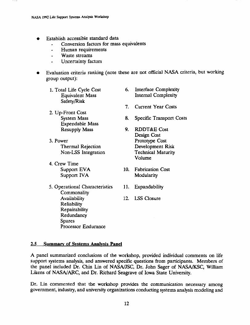
Evaluation criteria ranking (note these are not official NASA criteria, but working
group output):
1. Total Life Cycle Cost
Equivalent Mass
Safety/Risk
2. Up-Front Cost
System Mass
Expendable Mass
Resupply Mass
3. Power
Thermal Rejection
Non-LSS Integration
4. Crew Time
Support EVA
Support IVA
,
.
8.
9.
Interface Complexity
Internal Complexity
Current Year Costs
Specific Transport Costs
RDDT&E Cost
Design Cost
Prototype Cost
Development Risk
Technical MaturityVolume
10. Fabrication Cost
Modularity
5. Operational Characteristics
Commonality
Availability
Reliability
Repairability
Redundancy
SparesProcessor Endurance
11. Expandability
12. LSS Closure
2.5 Summary of Systems Analysis Panel
A panel summarized conclusions of the workshop, provided individual comments on life
support systems analysis, and answered specific questions from participants. Members of
the panel included Dr. Chin Lin of NASA/JSC, Dr. John Sager of NASA/KSC, William
Likens of NASA/ARC, and Dr. Richard Seagrave of Iowa State University.
Dr. Lin commented that the workshop provides the communication necessary among
government, industry, and university organizations conducting systems analysis modeling and
12
NASA 1992l._eSupportSystemsAnalysLsWorkshop
testing. However, activity reports from NASA would have been valuable to this
communication. He recommended follow-up working relationships be pursued as necessary
for increasing the effectiveness of life support systems modeling and testing efforts. These
continued communications and working relationships may alleviate some of the very strong
problems of obtaining data for various systems and technologies because of "proprietary"
type data.
William Likens indicated that the working groups made progress far beyond that made
during the 1991 workshop. He reinforced the ideas resulting from all four working groups
that testing and modeling guidelines are necessary for comparisons and integration of efforts
throughout government, industry, and university organizations. He recommended that flight
testing and data collection be conducted at early stages of research and development. Aneffort should be made to list the various tests that should be conducted in the next five years
aboard reduced gravity simulation aircraft, such as the KC-135, and the Shuttle. Dr. Lin
added that the majority of testing on systems to date has been short-duration 1-g testing
which needs to evolve to longer-duration 1-g testing and flight testing.
Dr. Richard Seagrave commented that more communication is needed at the working level
for integration of data and requirements. He indicated that additional focus toward
gathering consistent data on the requirements and goals of application missions should be
applied. He noted that there appears to be a lack of regard for analysis and testing of
integrated components, subsystem and system elements. Such integration analysis must
include trade-off and sensitivity studies on the various technologies and variabilities on the
human element. Life support systems analysis must be much more extensively integrated
into the design and development process.
Dr. John Sager reinforced the need for parallel modeling and testing. Although the
development approaches used in the systems analysis community have improved significantly
even from one year ago, he feels that we tend to lock into the old technologies because of
the lack of available data on new technologies. On this comment, Dr. Seagrave added that
the life support systems must push technology development in areas identified as being high
pay-off rather than being pulled by technology developers. A basic scientific research base
should be "shored up" to support such a transition. Dr. Sager also commented that the
development of guidelines and standards should not be "splintered off' into an effort by a
separate NASA committee but, instead, be developed by experts with actual experience in
modeling, testing, and operating life support systems.
Additional comments from workshop participants are summarized as follows:
Chemical process engineering talent, techniques, and tools must be much more
prominent in future systems analysis. These resources are not new and have been
proven and refined by the chemical processing industry and supporting university
community. The life support systems analysis problems are not very different from
standard analysis done for researching, evaluating, and developing commercial
chemical processing plants.
13
NASA 1992 Life Supporl Syslems Analysis Workshop
Both physical/chemical and biological life support technologies must be analyzed in
similar manners and compared across similar baseline assumptions. Ultimately, the
optimum system may be a hybrid of the two classes of technology.
When analysis is conducted, the results should be accompanied by a rigorous and
complete set of assumptions such that the results are not misinterpreted or unfairly
compared to results of other analyses.
The problem of analyzing, developing, and implementing a regenerative life support
system is so multi-disciplinary that civil and developmental engineering firms may be
valuable contributors to future workshops.
14
NASA 1992 Life Support Systems Analysis Workshop
3.0 SYSTEMS ANALYSIS MODELING
AND EXPERIMENTAL VALIDATION/VERIFICATION
The basic premise for prototype testing and systems analysis is to determine and predict
component, subsystem, and system performance accurately over a wide range of operating
conditions. Analysis and modeling can support the understanding of performance with great
versatility in assessing operational, design, and technology alternatives; however, analysis and
modeling is not fully reliable in providing solutions that correspond in all instances to real
hardware performance. On the other hand, prototype testing provides actual experience and
performance data, but cannot cost-effectively be conducted to determine performance over
a wide range of operational, design, or technology alternatives. Thus, both approaches must
be used interactively to provide a performance estimation capability that is both accurate
to actual hardware/software implementations and flexible to address a wide range ofalternatives.
The importance of iteration between systems analysis modeling and experimental validation
and verification was initially cited by working groups during the 1991 workshop. During the
1992 workshop, this working group investigated in more detail specifics of data exchange and
performance validation and software verification procedures between systems analysis
modeling and hardware development/testing. The working group also discussed the issue of
scale-up as it applies to this modeling/test bed iteration. The working group report is
contained in Appendix C.1. A summary of the working group results is followed by morein-depth discussion.
Q Parameters to be validated are dependent on the subsystem (e.g., in/out flow streams,
materials/media).
Minimum data set must be defined to assure validation
Fundamental operating principles and trends should be validated
Performance over lifetime should be validated
Establish baseline guidelines for subsystems process/prototype.
"Real" application conditions
- Standardized feed compositions
- Minimum acceptable scale
Model and prototype hardware should be "co-developed."
- Requirements and acceptable bounds on performance parameters
- Data uncertainty
- Instrumentation and sampling frequency
Baseline assumptions in modeling and testing
Additional information is needed to adequately scale-up hardware.
Characterization of each component (e.g., throughput, materials, drawings)
- Expected non-linearities and boundary conditions in scale-up
15

NASA 1992 Life Support Systems Analysis Workshop
• Guidelines for experimentation and model validation are needed.
Communication protocol is needed between groups involved in modeling and
experimentation efforts, and among the modeling/experimentation effort at the
various organizations.
3.1 Validation Parameters
The working group discussed test data which would be necessary to assure that a particular
model or analysis tool was valid. Several factors influence the needed data items including
the inputs, assumptions, and actual modeling parameters being used, the data needed to
determine performance, definition of the data that can be collected from the tests, and data
that represent or are indicative of the basic performance of the technology. Much of this
data identification is specific to the technology being modeled and tested, and would be
defined by the fundamental operating principles of the technology. This data could be
refined through sensitivity analysis to determine which data most influences the ultimate
performance.
The working group recommended that a minimum number of data be identified and
compared between models and hardware tests that would assure that the analysis models
will predict accurate results. Basic parameters necessary for validation include: (1)
characterization of the flow streams in and out of the component, (2) power consumption,
and (3) thermal control requirements. Additional data should be taken to characterize the
flow or performance of any special materials or media used such as sorbents, membranes,
etc. Performance validation data must be addressed over the lifetime of the component.
3.2 Guidelines for Prototype Development and Testing
Prototypes must be developed to yield test data that are meaningful to "real" applications.
The working group identified potential problems that have been existent in developing and
testing hardware prototypes, and made recommendations that would alleviate some of these
problems. Past prototypes have been designed at a much smaller scale than needed for their
ultimate applications, and appropriate data has been used to scale up hardware. Feed
compositions have been relatively pure and theoretically optimal with little investigation of
the performance sensitivity of the prototype under the suboptimal feed compositions that
are much more likely to occur in true application.
The working group recommended that guidelines be developed and implemented for
developing and testing prototypes. These guidelines would support determination of the
appropriate sizes of prototypes, compositions of feed stocks, and test conditions. The
guidelines for sizing should include recommendations based on the mission applications
(such as the number of persons to support, and the mission duration) and integration
considerations with other components and other systems. The working group felt that there
was some minimum prototype size that could be identified as the smallest scale prototype
for any given life support technology. Guidelines on feed stock compositions should outline
16
NASA 1992 Life Support System-¢ Analysis Workshop
baseline feed stocks for various components, as well as feed stock variances from the
baseline that represent potential real application conditions. These feed stocks would also
accommodate sensitivity studies on the variable aspects of humans as processing elements.
3.3 Co-Development of Models and Development Hardware
The working group recommended that analysis models and hardware prototypes be
developed in parallel and interactively. In this way, modeling could influence hardware
testing designs to accommodate appropriate instrumentation, while hardware development
could influence modeling through identification of specific performance requirements and
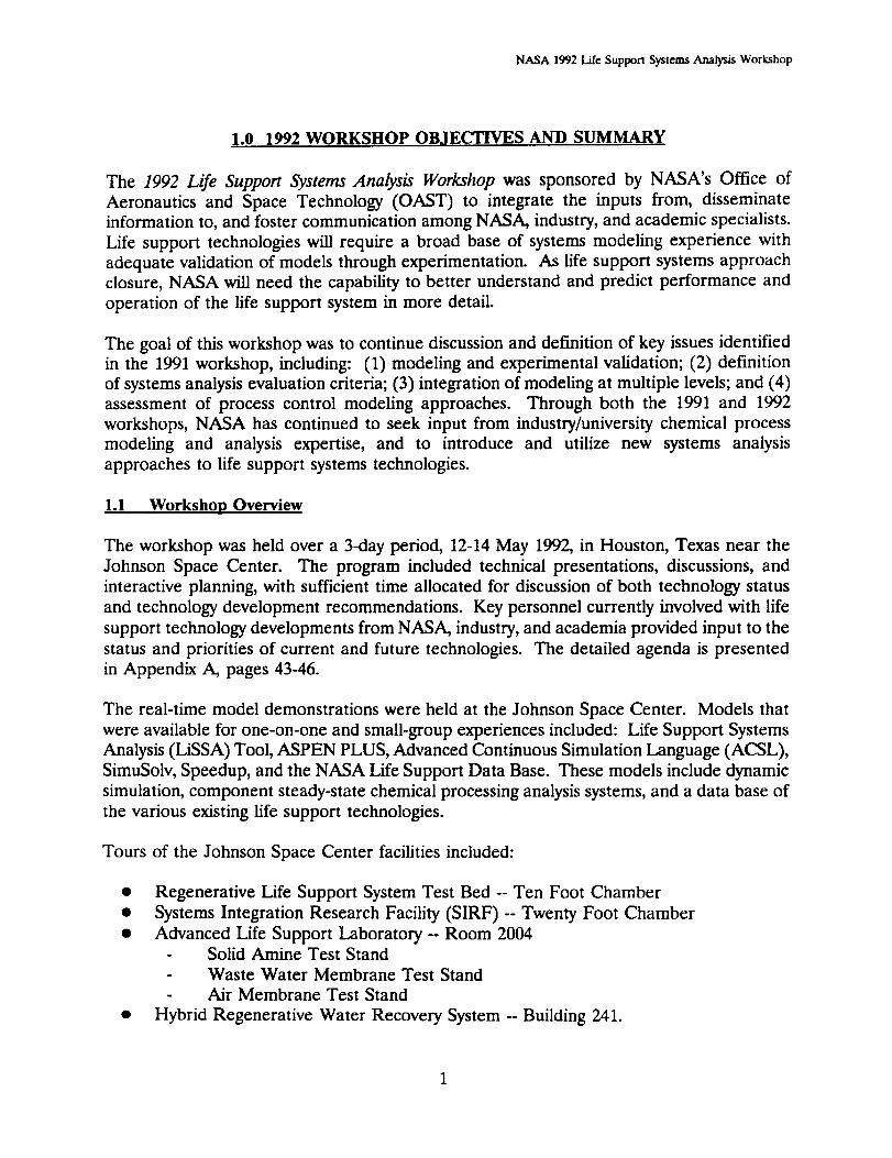
operational/design boundary conditions and envelopes. Figure 1 provides a recommended
track of co-development of analysis/models and hardware prototypes. The level of detail in
testing and modeling increases for both the models and the hardware as one approaches
implementation.
Modeling and analysis results will provide insight to high pay-off operation and design
approached to be tested and verified. This should more rapidly evolve the technology
development to higher performance. Hardware testing verifies the accuracy of modeling
results and predictions, and also gives indication of estimation uncertainties and accuracies.
Through this parallelism and interaction, NASA may be assured to have modeled the best
solution to the entire problem that can realistically be developed and operated with the
predicted performance. Likewise, hardware developments will not proceed to final stages
without consideration of operations and design alternatives that increase performance at the
component, system, or mission level.
A recommended approach in data generation and collection in the co-development of
hardware and model is as follows:
• Establish a minimum data set needed to validate model (see Section 3.1)
• Quantify acceptable bounds of operation and data collection
• Determine and record uncertainty of data predicted and collected
• Establish appropriate method for instrumentation of chemical analysis
• Determine most appropriate sensors and sites for measuring parameters
• Establish appropriate sampling frequency
• Verify accuracy of predicted vs. actual results between test and model
- Experimental protocol should be well documented
- Model assumptions should agree with test protocol
- Protocol should incorporate minimum number of trials required for statistical
significance
A rigorous communication protocol is needed between modeling and experimentation efforts
within the same organization and among government, industry, and university sectors. Not
only will this promote more coordinated modeling and testing, but it will also reduce
duplication of effort, and enhance the comparability of results from various sources.
17

NASA 1992 Life Support Systems Analysis Workshop
CO-DEVELOPMENT OF HARDWARE AND ANALYTICAL TOOLS
HARDWARE TESTING
COLLECT ENGINEERING DATA
I POSSIBLE FLIGHT TEST
[LABORATORY PROTOTYPE ]_
SELECT BASIC CONFIGURATIONANCOLLECT ENGINEERING DATA
POSSIBLE FLIGHT TEST
SUBSYSTEM/PROCESS PROTOTYPE I_
SCALE UPSUBSYSTEMSAND TEST
!
I FULL SCALE INTEGRATED TESTW/O AND W/HUMAN SUBJECTS
INCORPORATE PROCESS CONTROLINCORPORATE PERFORMANCE CRITERIAMINIMUM SCALE ESTABLISHEDMIMIC INTENDED APPLICATION
ENDURANCE TESTINGUSE REAL FEEDSPERTUBATION TESTINGCONTINUOUS RECYCLING
OSSIBLE FLIGHT TEST
_ BREADBOARD/ 1_INTEGRATED TESTBED
SENSITIVITY STUDIESINTEGRATION STUDIESOPTIMIZE CONTROL
I
Figure 1.
MODELING
,._. [ REACTION MODEL/
""- [ MOLECULAR SIMULATION
"-["1 BASIC MODEL ]
.-_- IREFINED MODEL ]
SUPPORT HARDWAREPROCESS CONTROLWARNING FLAGS
_ [ INTEGRATED MODEL ]
_.._[ INTEGRATE MODEL W1TH ]HUMAN SIMULATION
Analysis Models and Hardware Prototypes Should Be Co-Developed
18
NASA 1992 Life Support Systems Analysis Workshop
Guidelines instituted by NASA would help establish the communication protocol and
promote more standardized and integrated modeling and validation efforts within the life
support community. The result would be improved and more accurate modeling and testing
results, more usable and reliable data from research for modeling and analysis, and
integration of more trade-off and sensitivity studies within the testing and experimentation.
3.4 Data Necessary for Scale-up
Accurate scaling analysis within life support systems analysis is very important to increase
the versatility of the model and to address a wide range of mission and systems applications.
Scaling up fi'om small-scale prototype results can be very inaccurate, and is especially
inaccurate if the proper data is not considered. Each component needs to be considered
during the scaling process with at least the following information:
• Dimensioned engineering drawings
• Mass, energy, and composition throughputs• Construction materials
• Data base of user experience
In addition, the component small-scale prototypes should include identification of limits of
applicable scaling, including non-linearities and boundaries, for which extrapolation are no
longer realistic. For example, a certain technology may have been prototyped at a ¼ scale
of a 4-person lunar base. Of course, non-linear scaling laws must be followed where
necessary to include volumes of storage vessels and flow system masses. Scaling of that
prototype may be valid for the 4-person crew but not valid for a 16-person crew, where a
significantly different technology would be used within the system.
3.5 Additional Analysis and Effort Needed for Planned Experimentation
The working group identified several areas of study and analysis efforts that should be
integrated with currently planned tests and experiments:
Variable Pressure Growth Chamber (VPGC)
- Characterization of local chamber environment (e.g., irradiance, temperature,
nutrient distribution, etc.)
- Predict effect of local environment on plants- Substrate-nutrient solution interactions
- Effect of plant-produced contaminants on physiochemical hardware and vice-versa
Systems Integration Research Facility (SIRF)- Nominal mass balance assessment
- Determine measurements and instrumentation
- Mass, energy, and chemical interactions of plants and humans
- Determination of metabolic profile and approach of the human simulator
19
NASA 1992 Life Support Systems Analysis Workshop
3.6
Crop Growth Research Chamber (CGRC)
- Total systems characterization and modeling
- Definition of limits of performance from biological interactions of multiple
species
General Life Support System Experimentation
- Identify and prioritize goals of the life support systems developments (i.e.,
strategic plan)
- Identify, in more detail and with more standard assumptions, the input and
output flow streams of the existing life support system components
- Identify standard instrumentation and measurement approaches
- Total systems characterization of the prototypes and test beds- Determination of control schemes
- Collect as much existing data as possible and integrate into the modeling.
Systems Analysis Modeling and Experimental Validation/Verification Working Grouu
Participants
Dr. Liese DaU-Bauman (Lead)Grant Bue
Dr. Susan Fuhs
Stephen Gustavino
Gary Hudman
Dr. Jimmy L. Humphrey
Frank F. Jeng
Kevin E. Lange
Andrew McGough
Dr. Naresh Rohatgi
Firooz Rasouli
Dr. John C. Sager
Dr. Jack M. Spurlock
NASA Johnson Space CenterLockheed
AiResearch
McDonnell Douglas
Space Biosphere Ventures
JL Humphrey & AssociatesLockheed
Lockheed
Aspen TechnologyJPL
ElectroCom GARD
NASA KSC
S&A Automated Systems
20
NASA 1992 I__e Support Systems Analysis Workshop
4.0 APPLICATION OF SYSTEMS ANALYSIS TO PROCESS CONTROLS
The control system for any life support system can range from a totally automated, quick-
response system with system health management and evasive action capability to a very
simple open loop control system with significant human interaction. The degree of
automation, level of control, and sophistication of the control system are major decisions that
can be made only with accurate data on the effects of these alternatives on life support
system performance, trade-off and sensitivity analysis relating to the power, mass,
computation, human, and other resources required by the control system as a function of the
reliability, operational performance (nominal operation as well as start-up, shut-down, and
other transients), and maintainability of the system.
Systems analysis based on steady state operation is adequate to assess system parameters
such as mass, volume, average power demand, and other valuable resources for a given state
of operation. However, stable operation within any given control envelope during start-up,
shut-down, and other transients, as well as during various emergency conditions, requires
dynamic process modeling and analysis of dynamic system behavior. This working group
attempted to identify dynamic systems attributes to be estimated through dynamic process
models and interactive control models, and also discussed the relationship of dynamic
systems attributes to actual systems control.
Definition of the parts of the system that should be controlled, and the degree to which the
system should be controlled, are the first issues which must be addressed. Systems analysis
and modeling of the control system could address key considerations against the resource
expenditure required to develop and provide various levels of control. Key designconsiderations include:
How many control parameters are necessary for reliable life support systemoperation?
How simplistic can the method of control be while maintaining adequate robustness
and providing adequate system health management?
What level of sophistication is needed and desired given limited computationalresources available on-board?
Is operational control optimization necessary?
- Optimization on which parameters?
- Do these parameters change in different operating regimes?
- How many parameters are necessary for optimization?
21
NASA 1992 Life Support Systems Analysis Workshop
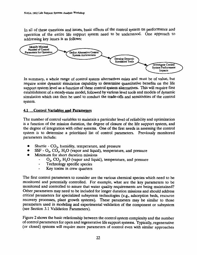
In all of these questions and issues, basic effects of the control system on performance and
operation of the entire life support system need to be understood. One approach to
addressing key issues is as follows:
of Conm31 _
for_
In summary, a whole range of control system alternatives exists and must be of value, but
require some dynamic simulation capability to determine quantitative benefits on the life
support system level as a function of these control system alternatives. This will require first
establishment of a steady-state model, followed by various level tools and models of dynamicsimulation which can then be used to conduct the trade-offs and sensitivities of the control
system.
4.1 Control Variables and Parameters
The number of control variables to maintain a particular level of reliability and optimization
is a function of the mission duration, the degree of closure of the life support system, and
the degree of integration with other systems. One of the first needs in assessing the control
system is to determine a prioritized list of control parameters. Previously monitored
parameters include:
Shuttle - CO2, humidity, temperature, and pressure
SSF - 02, CO2, H20 (vapor and liquid), temperature, and pressureMinimum for short duration missions
- 02, CO2, H20 (vapor and liquid), temperature, and pressure
- Technology specific species
- Key toxins in crew quarters
The first control parameters to consider are the various chemical species which need to be
monitored and potentially controlled. For example, what are the key parameters to be
monitored and controlled to assure that water quality requirements are being maintained?
Other parameters may need to be included for longer duration missions and should address
critical parameters for specialized subsystem technologies (e.g., adsorption beds, resource
recovery processes, plant growth systems). These parameters may be similar to those
parameters used in modeling and experimental validation of the component or subsystem
(see Section 3.1 Validation Parameters).
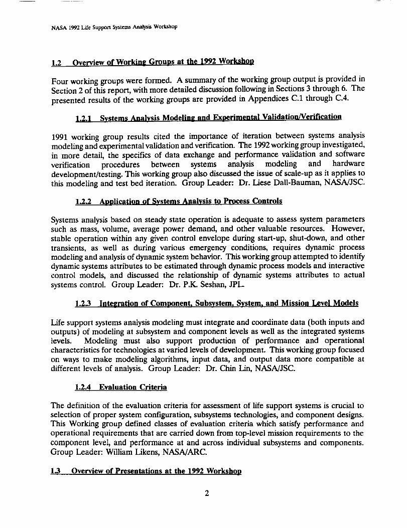
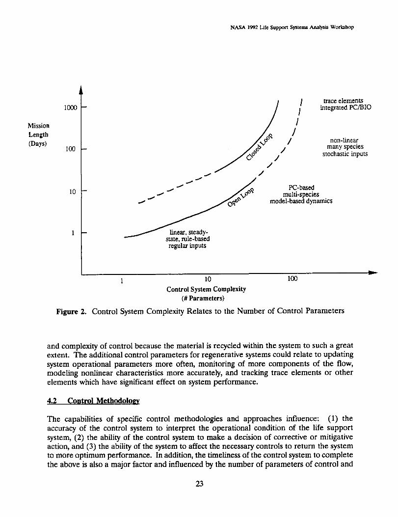
Figure 2 shows the basic relationship between the control system complexity and the number
of control parameters for open and regenerative life support systems. Typically, regenerative
(or closed) systems will require more parameters of control even with similar approaches
22
NASA 1992 Life Support Systems Analysis Workshop
Mission
Length
(Days)
1000
100
10
J<>° //jJ /
_ linear, steady-state, rule-bas_regular inputs
/
III
//
traceelementsintegratedPC/BIO
non-linearmany species
stochastic inputs
PC-basedmulti-species
model-based dynamics
v
Figure 2.
1 10 100
Control System Complexity
(# Parameters)
Control System Complexity Relates to the Number of Control Parameters
and complexity of control because the material is recycled within the system to such a great
extent. The additional control parameters for regenerative systems could relate to updating
system operational parameters more often, monitoring of more components of the flow,
modeling nonlinear characteristics more accurately, and tracking trace elements or other
elements which have significant effect on system performance.
4.2 Control Methodology
The capabilities of specific control methodologies and approaches influence: (1) the
accuracy of the control system to interpret the operational condition of the life support
system, (2) the ability of the control system to make a decision of corrective or mitigative
action, and (3) the ability of the system to affect the necessary controls to return the system
to more optimum performance. In addition, the timeliness of the control system to complete
the above is also a major factor and influenced by the number of parameters of control and
23

NASA 1992 Life Support Systems Analysis Workshop
optimization, and the level of computational capability allotted to the control system. More
sophisticated control methodologies and approaches can improve the performance (including
reliability and robustness) of the overall life support system.
Figure 3 shows a trend of expected operational cost of the life support system as a function
of the control system sophistication. The reductions of operational performance may be
accomplished through: (1) closer maintenance of system operation to optimum performance;
(2) increased operational bandwidth and increased knowledge of the system that allows the
ability to respond to variances; and (3) reduced crew time and other support resources to
conduct health management and maintenance of the system. Several different control
methods may be implemented from the more rudimentary equation-based architectures such
as position-integral-derivative (PID) and single-input, single-output (SISO) to the more
model-based and rule-based control approaches, and from centralized control to
Operational Cost vs. Control System Sophistication
OperationalCost RULE-BASED
OPID _ BLOCK
Required BufferDeviation from Optimal Operation
MODEL-BASED
CENTRALIZED
0
v
Control System Sophistication
Figure 3. Life Support Systems Operational Performance
Can Be Increased Through Increased Control Sophistication
24

NASA 1992 Life Support Systems Analysis Workshop
decentralized control. The ultimate goal of choosing a specific control approach will be to:
(1) optimize performance of the life support system; (2) and maximize the reliability,
robustness and maintainability of the life support system; and (3) minimize the requirements
of computational resources and other support resources. Trade-off and sensitivity analysesneed to be conducted on the various methods and approaches and the specific
implementations of the control system within these approaches to identify the overall
benefits to the life support system. This will require dynamic simulation tools to model the
control system and life support subsystems which are discussed in the next section.
4.3 Dynamic Simulation
Modeling and assessment of the control system of the life support system will require some
degree of dynamic simulation. Dynamics modeling can provide significant insight and
prediction of operational performance during start-up, shut-down and transient conditions
in operations within the life support system. Dynamic simulation of the control system will
also allow identification of life support system design parameters that may be changed or
altered to allow easier control of the system with higher control performance or reduced
research requirements needed for control. However, the degree of dynamic simulation is
not yet well determined. The level of dynamic simulation required will depend on the time
frame and frequency resonance of the interacting flows and components within the life
support system, the linearity of the life support system as a whole or the ability to assemble
linear sub-models within the life support system, and the level of detail of the results desired
and the input data available. Typically, in the chemical process industry, dynamic modeling
of a chemical process begins with an accurate steady-state model from which point designs
and point conditions can be validated in experimentation by also be used to validate the
dynamic model under certain constraining conditions. Currently, the life support systems do
not have a valid full-scale steady-state model representation that is validated through
experimentation. Thus, this should be the first step in developing dynamic modeling:
develop a good steady-state model of the life support system.
Once the steady-state model is established and verified, dynamic modeling can reliably
evolve; however, it is undetermined what level of detail is required or what level of
sophistication within the dynamics control dynamic modeling is required to adequately
understand and represent the life support system hardware. The level of detail required will
only be determined through an iteration of dynamic modeling and experimentation beginning
at a top-level of detail to verify accurate results of such dynamic modeling. If accurate
modeling can be accomplished with a top-level dynamic model, more detailed modeling may
not be required. Through this iteration, developers will learn whether linear representation
of certain components and subsystems is adequate and where non-linearities exist, and also
where non-linearities do and do not affect significantly the performance of the system.
Developers will also learn whether simple equation-based control systems may be adequate
over model-based control systems.
Determination of whether the life support system is dynamically stable enough to run with
open-loop control can be made in this iteration of dynamic modeling and experimentation.
25

NASA 1992 Life Support Systems Analysis Workshop
Determination of whether the life support system is dynamically stable enough to run with
open-loop control can be made in this iteration of dynamic modeling and experimentation.
Ultimately, the appropriate degree of closed-loop control necessary to provide reliable
operation can be determined through such modeling and testing. This assessment can be
done at the life support system level, subsystem level, and component level. An indication
of this degree of closure is a resiliency index, where P represents parameters of control and
C represents the complexity of control, which can be used to compare controllability of one
control system to another:
Resiliency index = min f(P,C)<I and max t { yl{t) Y2(t)} <12 , 2
Once the level of necessary dynamic simulation is defined and the modeling is pursued to
the point of verification with experimentation, trade-off and sensitivity analyses may proceed
to determine the performance benefits as a function of the control methodology and
approach.
4.4 Control System Modeling to address Trade-offs and Sensitivities
The dynamic simulation discussed above should be used to address control system
alternatives in the overall performance of the life support system. As was shown in Figure
3, operational performances can be increased through use of more sophisticated control
methodologies and approaches; however, there are additional costs such as computational
resources and development resources which must be also considered in these trade-off and
sensitivity analyses. Ideally, the value of each of the various control methods and
approaches would be assessed and their relative value would be determined; however,
investigation of trends from a few baseline alternatives may be sufficient. In other words,
we need to quantify such things as the impacts of different control approaches (e.g., model-
based control, position-integral-derivative control).
Another trade-off which needs to be considered in these analyses is: how much of the
control system needs to be real-time and on-board vs. off-loading some of the control system
to off-line ground-based systems that are activated on an as-needed basis.
26

NASA 1992 Life Support Systems Analysis Workshop
4.5 Application of Systems Analysis to Process Controls Working Group Participants
Dr. P.IC Seshan (Lead)Dr. Richard Chu
Thomas M. Crabb
Gani Ganipathi
Dr. Patrick McCroskeyCarl McFadden
Dr. Robert Farrell
Linda JerngDr. Thomas Lo
Dr. Vasilios Manousiouthakis
Dr. Richard Seagrave
Dr. Randy StahlSteve Rowe
JPL
Lockheed
ORBITEC
JPL
Dow Chemical
McDonnell Douglas
NY Polytechnic UniversityLockheed
Purdue UniversityUCLA
Iowa State University
NASA JSC (currently at Texas A&M)AiResearch
27

NASA 1992 Life Support Systems Analysis Workshop
THIS PAGE INTENTIONALLY LEFT BLANK
28 4

NASA 1992 Life Suppor[ Systems Analysts WorkShop
5.0 INTEGRATION OF COMPONENT, SUBSYSTEM, SYSTEM
AND MISSION LEVEL MODELS
Several levels of modeling are required to assess a technology. The basic performance and
operational characteristics can be modeled through chemical process models in static and
dynamic conditions. The components may be integrated into subsystem and system models
for estimation of performance. These integrated models may take many forms, ranging from
detailed static and dynamic chemical process models to flow sheets, relational spreadsheets
and data bases. In all life support systems analysis modeling, the models must integrate and
coordinate modeling data (both inputs and outputs) of modeling at subsystem and
component levels, as well as the modeling at the integrated systems levels. This working
group focused on ways to make modeling algorithms, input data, and output data more
compatible at different levels of analysis. The following statements summarize the discussion
results of the working group.
• A wide variety of tools is used for various levels of detail and various systems levels.
Many of the tools are developed independently of one another which makes
integration of the data input and output difficult or impossible.
Attempting to generate a standard set of tools for all system levels and all levels of
detail may be difficult.
Guidelines should be established for the modeling objectives at the various levels and
for the tools used at the various levels.
- Assumptions
- Physical/Chemical Data
Data input/output flows from one level to another
5.1 Wide Variety of Tools
The wide range of modeling from detailed chemical process analysis to mission-level trades
of life support technologies requires an equally wide variety of tools. Some of the detailed
modeling may be substituted by bench testing. In some cases, bench testing may be required
to support rigorous detailed chemical process modeling. However, the chemical process
industry does not attempt a large-scale experiment without some basic theoretical
understanding of the process through modeling.
For life support applications, some modeling at the detailed level has been accomplished for
the air revitalization applications including ASPEN PLUS models of chemical processes used
in CO 2 collection and reduction and water electrolysis. Less detailed modeling and analysis
can be found for the water systems for space application.
The working group resolved that additional detailed modeling of the components should be
pursued but integrated into the higher level modeling and the testing efforts../
PRE6EDING PAGE BLANK NOT FILMED 29 _,_"_/ _fi2_h_3_ < '_- . ....................... _.

NASA 1992 Life Support Systems Analy_ Workshop
Modeling is required for analysis at several levels of design and technology development.
The working group divided the levels of modeling into four major areas where modeling
parameters and approaches may be grouped and categorized. These include:
Technology Assessment / Mission Analysis: The screening of technologies and
subsystems designs on a top-level-type analysis. This analysis is used for sensitivity
and trade-off studies based on mission requirements.
System Flowsheet Analysis: A more detailed performance assessment and subsystem
sizing of integrated subsystems (can also be used to assess integration alternatives but
requires use of detailed process data). This type of analysis is typical of Phase A andPhase B studies.
System Level Detailed Modeling: A detailed analysis and modeling of integrated
subsystems and components for system design verification and validation for meeting
mission requirements and system operation support. These models do not typically
include their own process models for the integration of components and are used inPhase C/D.
Detailed Component and Subsystems Modeling: The detailed chemical process
modeling to predict performance and fundamental characteristics of the component
or subsystem level. This type of analysis and modeling is used for hardware
performance and operational verification.
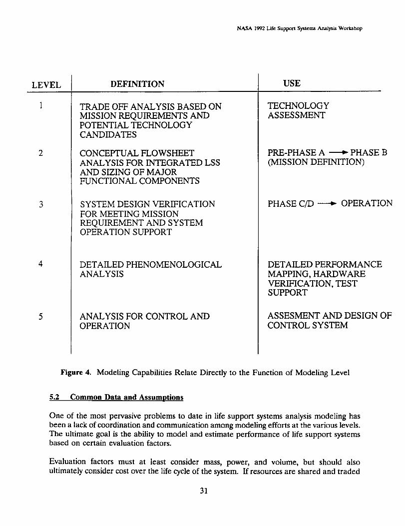
Figure 4 shows the modeling tools cited by the working group (not an all-inclusive list) to
characterize some general capabilities at the various levels of analysis. In this figure, an
indication is made as to whether certain models apply with a static, transient, or dynamic
capability. The recommendation made by the working group included an agreement that
various approaches and analysis capabilities should contain the standardized guidelines for
anyone conducting life support systems analysis. This recommendation does not necessarily
mandate a single tool as the standard, but suggests that certain analytical calculations be
made for certain levels and for certain types of modeling applications. Figure 5 shows the
working group's approach for modeling at different levels of analysis.
Another problem cited by the working group was the lack of input data available from the
original developers of component hardware. In some cases, no modeling was required by
the procuring contract and, thus, either none was available, or the modeling and results were
considered proprietary and non-releasable. Every contractor has an approach to modeling
and testing hardware that includes the conduct of sensitivity/trade-off studies and validation
of performance. Each approach includes use of several tools, some of which are unique to
the supplier. Future contracting for hardware should requilr_ sorlrle baseline level of
modeling and reporting of data. including assumptions, basic modeling algorithms, andresults.
30
NASA 1992 Life Support Systems Analysis Workshop
LEVEL
2
3
4
5
DEFINITION
TRADE OFF ANALYSIS BASED ON
MISSION REQUIREMENTS ANDPOTENTIAL TECHNOLOGY
CANDIDATES
CONCEPTUAL FLOWSHEET
ANALYSIS FOR INTEGRATED LSS
AND SIZING OF MAJORFUNCTIONAL COMPONENTS
SYSTEM DESIGN VERIFICATION
FOR MEETING MISSION
REQUIREMENT AND SYSTEMOPERATION SUPPORT
DETAILED PHENOMENOLOGICALANALYSIS
ANALYSIS FOR CONTROL AND
OPERATION
USE
TECHNOLOGY
ASSESSMENT
PRE-PHASE A _ PHASE B
(MISSION DEFINITION)
PHASE C/D _ OPERATION
DETAILED PERFORMANCE
MAPPING, HARDWARE
VERIFICATION, TESTSUPPORT
ASSESMENT AND DESIGN OF
CONTROL SYSTEM
Figure 4. Modeling Capabilities Relate Directly to the Function of Modeling Level
5.2 Common Data and Assumptions
One of the most pervasive problems to date in life support systems analysis modeling has
been a lack of coordination and communication among modeling efforts at the various levels.The ultimate goal is the ability to model and estimate performance of life support systemsbased on certain evaluation factors.
Evaluation factors must at least consider mass, power, and volume, but should also
ultimately consider cost over the life cycle of the system. If resources are shared and traded
31

NASA 1992 Life Support Systems Analysis Workshop
LEVEL 12 3 4
SYSTEM SIZING &FLOWSHEET
BALANCE (LiSSA)
SYSTEMINTEGRATIONEVALUATION
CANDIDATESUBSYSTEM/TECHNOLOGY
MISSIONPARAMETERSLEVEL 1 TOLEVEL 2
SIZING ANDINTEGRATIONVERIFICATION
MISSIONPARAMETERS
INTERFACE REQ.IDENTIFICATIONBETWEENCOMPONENTS
FEED STREAMDATA
i
INTERFACE REQ.IDENTIFICATION
FEED STREAMDATA
DETAILEDCHARACTERISTICSOF INTERFACE/OPERATING REQs
TECHNOLOGYDATAUPDATE
SIZINGFEEDBACK
PERFORMANCEMAPS
DETAILEDCHARACTERISTICSOF INTERFACES
Figure 5.Modeling Approaches Recommended for Various Levels of Analysis
32
NASA 1992 Life Support Systems Analysis Workshop
among components and subsystems, the consideration of where to optimize performance iscritical. In some cases like these, the optimum performance of the system does not rely on
optimum performance of each component, but more on the integrated performance. Only
analysis with an integrated system level model can optimize the integrated performance.
Data may emanate from a large number of diverse sources. The modelers must be assured
that the input data is valid and accurate. If this is not fully achievable, then the next best
step is to assure that all modelers have access to the same data for input, such that the base
assumptions and underlying data from which the results emanate are similar and
comparable. This data includes standard physical and chemical properties which are
essential to comparable modeling results. The working group has had experience with
ASPEN PLUS, which provides a "clearinghouse" service from basic properties. Collection
and use of data in this manner should be explored for use in future modeling efforts.
Guidelines should be established for the modeling objectives and tools used at the various
levels. Assumptions must be standardized or, at the minimum, be listed as a part of the
results such that the results of various analyses are not unjustifiably compared. Physical and
chemical properties and data must also be standardized for similar reasons. Standardized
flow stream assumptions would also improve the consistency and comparability of analyses.
Documented guidelines for analysis could be developed throughout the modeling and
analysis community.
5.3 Integration of Conlponent, Subsystem, System and Mission Level Models WorkinR
Group Participants
Dr. Chin Lin (Lead)
Allen BacskayDr. Hal Couch
Joe Ferrall
Scott Gilley
Matt Kolodney
Roger von JouannaSassan Yerushalmi
NASA Johnson Space Center
NASA Marshall Space Flight CenterHamilton Standard
Jet Propulsion Laboratory
SverdrupLockheed ESC
BoeingLockheed ESC
33

NASA 1992 I.Me Support Systems Analysis Workshop
THIS PAGE INTENTIONALLY LEFT BLANK
34

NASA 1992 Life Support Systems Analysis Workshop
6.0 SYSTEMS ANALYSIS APPROACHES AND EVALUATION CRITERIA
Evaluation criteria that quantify the performance of life support systems must adequately
represent the mission and system requirements throughout the analysis and testing efforts.
Proper determination and prioritization of the criteria will support proper selection of
technologies through the sensitivity and trade-off analyses, and also guide the modeling,
testing, and control system development through definition of important parameters to be
modeled and monitored. Thus, subjective criteria are to be avoided, and quantifiable criteria
should form the basis of all analysis and testing.
Within the trade-off and sensitivity studies, the definition of the evaluation criteria for
assessment of life support systems is crucial to selection of proper system configuration,
subsystems technologies, and component designs. This working group defined classes of
evaluation criteria which satisfy performance and operational requirements carried down
from top-level mission requirements to the component level, and performance at and across
individual subsystems and components. A summary of the working group recommendations
follows:
Evaluation criteria ranking must not be subjective and must be quantifiable, indicating
the performance of the life support system with respect to life cycle costs.
Quantitative systems analysis methodologies
Safety: failure, hazard, and repair
Equivalent mass: mass, pressurized volume, energy, heat rejection, manpower
Research, design, development, testing and evaluation (RDDT&E) and life
cycle cost
Established accessible standard data
- Conversion factors for mass equivalents
- Human requirements
- Waste strew!ms
- Uncertainty factors
6.1 Evaluation Criteria Selection
The basis for all evaluation criteria should, at a minimum, consider mass, power, and
volume, with an ultimate tie to life cycle cost of the life support system. The life support
system may be divided into the RDDT&E, operations, and supportability. The RDDT&E
costs must be amortized across the life of the system. Typically, a system or technology
which has a high RDDT&E cost must have low operation and support costs to justify the
initial costs. Safety considerations are also very important to consider in the life support
system and must be quantifiable in the evaluation criteria. The working group went throughan exhaustive effort to list possible evaluation criteria and then prioritized them. The results
follow:
PRECEDING PAGE BLANK NOT FILMED 35

NASA 1992 Life Support Systems AnaJysi.s Workshop
1. Total Life Cycle Cost
Equivalent Mass
Safety/Risk
2. Up-Front Cost
System Mass
Expendable Mass
Resupply Mass
3. Power
Thermal Rejection
Non-LSS Integration
4. Crew Time
Support EVA
Support IVA
.
.
8.
9.
Interface. Complexity
Internal Complexity
Current Year Costs
Specific Transport Costs
RDDT&E Cost
Design Cost
Prototype Cost
Development Risk
Technical MaturityVolume
10. Fabrication Cost
Modularity
5. Operational Characteristics
Commonality
Availability
Reliability
Repairability
Redundancy
SparesProcessor Endurance
11. Expandability
12. LSS Closure
A system of components will not be evaluated on all of the above criteria. A consideration
of refinement to the evaluation criteria listed above must address the overlapping nature of
several of the criteria. One solution is to convert or define equivalences among variousevaluation criteria.
6.2 Standardized and Accessible Data
The working group endorsed provision of standardized data, including conversion factors,
human requirements, waste stream compositions and flow rate and uncertainty factors, would
support more comparable results in quantifying performance and the related evaluationcriteria.
Relationships among evaluation criteria may be used to quantify equivalents among those
criteria through the specific system technologies and designs. Conversions to mass
equivalents from power, volume, heat rejection, manpower (IVA and EVA), and other
important parameters would allow technology, component, and systems on a single
parameter, with some basic historical relationships between system mass and development,
launch, and operations. In addition, standardized human performance data should be
considered in these conversion efficiencies. Key conversion factors to consider include:
36

NASA 1992 Life Support Systems Analysis Workshop
Pressurized volume (in kg/m3): SSF, Skylab, and inflatable prototypes may be used
in development of example conversion parameters.
Energy (in kg/kWh): solar, battery, regenerative fuel cells, and nuclear may be used
in development of standard conversion parameters.
Heat rejection (in kg/kWh): two-phase radiator, cold plates, and various heat
exchangers may be used in development of standard conversion parameters.
Crew hours (in kg/crew-hour): IVA and EVA costs may be accumulated to some pre-
defined level for the development of standard conversion parameters.
Human characteristics should also be standardized including metabolic inputs and outputs
for nominal conditions and a nominal size crew, and for off-nominal conditioned. In this
way, the evaluations of technologies, components, and systems may be considered in bothnominal and off-nominal conditions to determine flexibility and robustness of the
performance. The same standards and variances of composition and flow rates must be
considered for flow streams among components and subsystems.
Uncertainty of input data and resulting output should be included with the data. Such
estimates and error bars are required to indicate the resolution of sensitivity and trade-off
studies such that evaluation conclusions are not drawn when results fall under the error of
the analysis.
6.3 Analysis Methodologies for Specific Criteria
Standardized or recommended analysis methodologies were identified by the working group
in areas of safety, equivalent mass, and RDDT&E costs. Safety analysis methodologies
require failure rates by failure mode, hazards, and repair rates. Equivalent mass analysis
methodologies must define specific scope for calculation of the equivalents such as:
• mass (kg): spares, systems hardware, process & distribution, expendables,consumables
• pressurized volume (m3): volumes for storage, operations, hardware
energy (kWh): power generation/collection, storage, and distribution for average and
peak levels
manpower (crew-hour): crew time for maintenance, operation, regeneration, or other
similar function during EVA and IVA
heat rejection (kWh): heat collection, transfer/distribution, and rejection for average
and peak levels.
37
NASA 1992I..ifcSupport SystemsAnalysisWorkshop
RDDT&E costs must have a well-defined scope of what is included and not included. These
costs should be cast in the terms of a "return on investment" analysis. Significant support
from the contractors to provide actual anticipated RDDT&E costs for various components
would provide a more accurate data base on these costs.
6.4 Evaluation Criteria Working Group Participants
William Likens (Lead)
Susan Doll
Dr. Alan Drysdale
Marybeth Edecn
Martha Evert
Robert Henson
KristinMcCarthy
Dr. Willy Sadch
Paul Shafcr
NASA Ames Research Center
Boeing
McDonnell Douglas
NASA Johnson Space CenterLockheed ESC
Lockheed ESC
Rockwell International
Colorado State UniversityLockheed ESC
38

NASA 1992LifeSupportSystemsAnalysisWorkshop
APPENDICES
A.
Be
Co
Do
Detailed Agenda ................................ 41
Workshop Participants ............................ 47
Working Group Presentations ....................... 51
Workshop Report Distribution ...................... 85
39

NASA 1992 l.Me Support SyT,tems Analysis Workshop
THIS PAGE INTENTIONALLY LEFT BLANK
40
NASA 1992 I.Jfc Supporl Systems Analysis Workshop
APPENDIX A Detailed Agenda
41
PREeEDING P/_IGE BLANK blOT F!LMED

NASA 1992 Life Support Systems Anal_is Workshop
THIS PAGE INTENTIONALLY LEFT BLANK
42
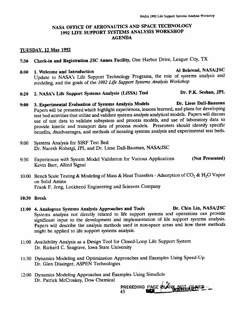
NASA 1992 Life Support Systems Analysis Workshop
NASA OFFICE OF AERONAUTICS AND SPACE TECHNOLOGY
1992 LIFE SUPPORT SYSTEMS ANALYSIS WORKSHOP
AGENDA
TUESDAY, 12 May 1992
7:30 Check-in and Registration JSC Annex Facility, One Harbor Drive, League City, TX
8:00 1. Welcome and Introduction Ai Behrend, NASMJSC
Update to NASA's Life Support Technology Programs, the role of systems analysis and
modeling, and the goals of the 1992 Life Support Systems Analysis Workshop
8:20 2. NASA's Life Support Systems Analysis (LiSSA) Tool Dr. P.IC Seshan, JPL
9:00 3. Experimental Evaluation of Systems Analysis Models Dr. Liese Dall-Bauman
Papers will be presented which highlight experiences, lessons learned, and plans for developingtest bed activities that utilize and validate systems analysis analytical models. Papers will discuss
use of test data to validate subsystem and process models, and use of laboratory data to
provide kinetic and transport data of process models. Presenters should identify specific
benefits, disadvantages, and methods of iterating systems analysis and experimental test beds.
9:00 Systems Analysis for SIRF Test Bed
Dr. Naresh Rohatgi, JPL and Dr. Liese Dall-Bauman, NASA/JSC
9:30 Experiences with System Model Validation for Various Applications
Kevin Barr, Allied Signal
(Not Presented)
10:00 Bench Scale Testing & Modeling of Mass & Heat Transfers - Adsorption of CO 2 & H20 Vapor
on Solid Amine
Frank F. Jeng, Lockheed Engineering and Sciences Company
10:30 Break
11:00 4. Analogous Systems Analysis Approaches and Tools Dr. Chin Lin, NASA/JSC
Systems analysis not directly related to life support systems and operations can provide
significant input to the development and implementation of life support systems analysis.
Papers will describe the analysis methods used in non-space areas and how these methods
might be applied to life support systems analysis.
11:00 Availability Analysis as a Design Tool for Closed-Loop Life Support System
Dr. Richard C. Seagrave, Iowa State University
11:30 Dynamics Modeling and Optimization Approaches and Examples Using Speed-Up
Dr. Glen Dissinger, ASPEN Technologies
12:00 Dynamics Modeling Approaches and Examples Using SimuSolv
Dr. Patrick McCroskey, Dow Chemical
PRE6EDING _{}[_ E_._ L,...PAGE43 ..
NASA 1992 Life Supporl Systems Analysis Workshop
12".30 Lunch
1"30 - 5:00 5. Working Group Meetings - ParaLlel working session #1 for the Working Groups
Systems Analysis Modeling and Experimental Validation/Verification - The importance of
iteration between systems analysis modeling and experimental validation and verification was
cited by working groups at last year's workshop. This working group will investigate in more
detail specifics of data exchange and performance validation and software verification
procedures between systems analysis modeling and hardware development/testing. This working
group should also discuss the issue of scale-up as it applies to this modeling/test bed iteration.
Group Leader: Dr. Liese Dall-Bauman, NASA/JSC.
Evaluation Criteria - The definition of the evaluation criteria for assessment of life support
systems is crucial to selection of proper system configuration, subsystems technologies, and
component designs. This Working group will work toward defining classes of evaluation criteria
which satisfy performance and operational requirements that are carried down from top-level
mission requirements to the component level, and performance at and across individual
subsystems and components. Group Leader: Vince Bilardo, NASA/ARC.
Integration of Component, Subsystem, System, and Mission Level Models - Life support
systems analysis modeling must integrate and coordinate data (both inputs and outputs) of
modeling at subsystem and component levels as well as the modeling at the integrated systems
levels. This working group will focus on means in which to make modeling algorithms, input
data, and output data more compatible at different levels of analysis. Group Leader: Dr. Chin
Lin, NASA/JSC.
Application of Systems Analysis to Process Control - Systems analysis based on steady state
operation is adequate to assess system parameters such as mass, volume, average power
demand, and other valuable resources. However, stable operation within any given control
envelope during start-up, shut-down, and other transients, as well as during various emergency
conditions, requires dynamic process modeling and analysis of dynamic system behavior. This
working group will attempt to identify dynamic systems attributes to be estimated through
dynamic process models and interactive control models, and will also discuss the relationship
of dynamic systems attributes to actual systems control. Group Leader: Dr. P.K. Seshan, JPL.
6:00 Dinner and Speaker
William Huffstetler, Manager, New Initiatives Office, NASA/JSC
South Shore Harbor
44
NASA 1992 Life Support Systems Analysis Workshop
WEDNESDAY, 13 May 1992
8:00 6. Dynamics Analytical Modeling and Process Control Dr. P.IL Seshan, JPL
Papers will focus on the past, current, and future methods and approaches to process control.Control hierarchies and methodologies should address potential levels of stability; effects of off-
nominal operation; levels of sensing and monitoring needed; potential for singularities and
instabilities; and control mechanisms for safety, redundancy, and reliability.
8:05 Steady State and Dynamic Systems Analysis in the Chemical Process Industries
Dr. Robert J. Farrell, Polytechnic University
8:35 Dynamic Evaluation of Technologies for Life Support Systems
Dr. Vasilios Manousiouthakis, UCLA
9:05 Modeling and Simulation Tools for Process Control Analysis
Stephen Rowe, Allied Signal
9:35 An Approach to the Integration of a Closed Ecological Life Support System
Dr. W. Lo, Dr. C.H. Lin, Dr. George Tsao; Purdue University
10:00 Break
10-..30 7. Systems Analysis Approaches & Evaluation Criteria William Likens, NASA/ARC
Papers will discuss various approaches and special topic issues related to life support systems
analysis. The ultimate goal is to provide quantitative estimation of life support system
performance in terms of mass, power, volume, thermal, resupply, reliability, and maintainability.
10:30 Future Development of Life Support Systems Evaluation Criteria
Vince Bilardo, NASA/ARC
(Not Presented)
10:50 Probabilistic Risk Assessment (PRA)
William C. Likens; NASA/ARC
11:10 Integration of Detailed User Component Models in ASPEN PLUS Simulations
Dr. Kevin E. Lange; Lockheed Engineering and Sciences Company
11:30 Modeling of Metabolic Flow-rates in a Closed Ecosystem
Dr. Willy Z. Sadeh; Colorado State University
11:50 Lunch
12:30 - 4-.30 8. Working Group Meetings - Parallel working session #2 for the Working Groups
5:00 9. Model Demonstrations - small groups and one-on-one
On-site demonstrations of models will be available for individuals and small groups that desire
to investigate general modeling capabilities, specific modeling approaches, specific model
examples.
45
NASA 1992 Life Support Systems Analysis Workshop
TItURSDAY, 14 May 1992
8:00 10. Working Group Presentations
Each of the working groups will present a list of key issues, a description of the status, and
recommendations for future efforts and developments within their respective scope.
10:00 Break
10:30 11. Systems Analysis Panel Wrap.Up
A panel will summarize conclusions of the workshop, provide individualized comments on life
support systems analysis, and to answer specific questions from participants.
11:30 Bus from Annex to Johnson Space Center
(Bus will provide return transportation back to Annex)
12:00 12. Tour of NASA Johnson Space Center Life Support Facilities NASA/JSC
12:00 Tour Building 7: SIR, 10-foot chamber (plants), and life support laboratory.
1:00 Depart Building 7
1:10 Tour Building 241: Hybrid regenerative water recovery system site.
1-.30 ADJOURN
46

NASA 1992 Life Support Systems Analysis Workshop
APPENDIX B Workshop Participants
47

NASA 1992 Life Support Syztems Anal_s Workshop
THIS PAGE INTENTIONALLY LEFT BLANK
48
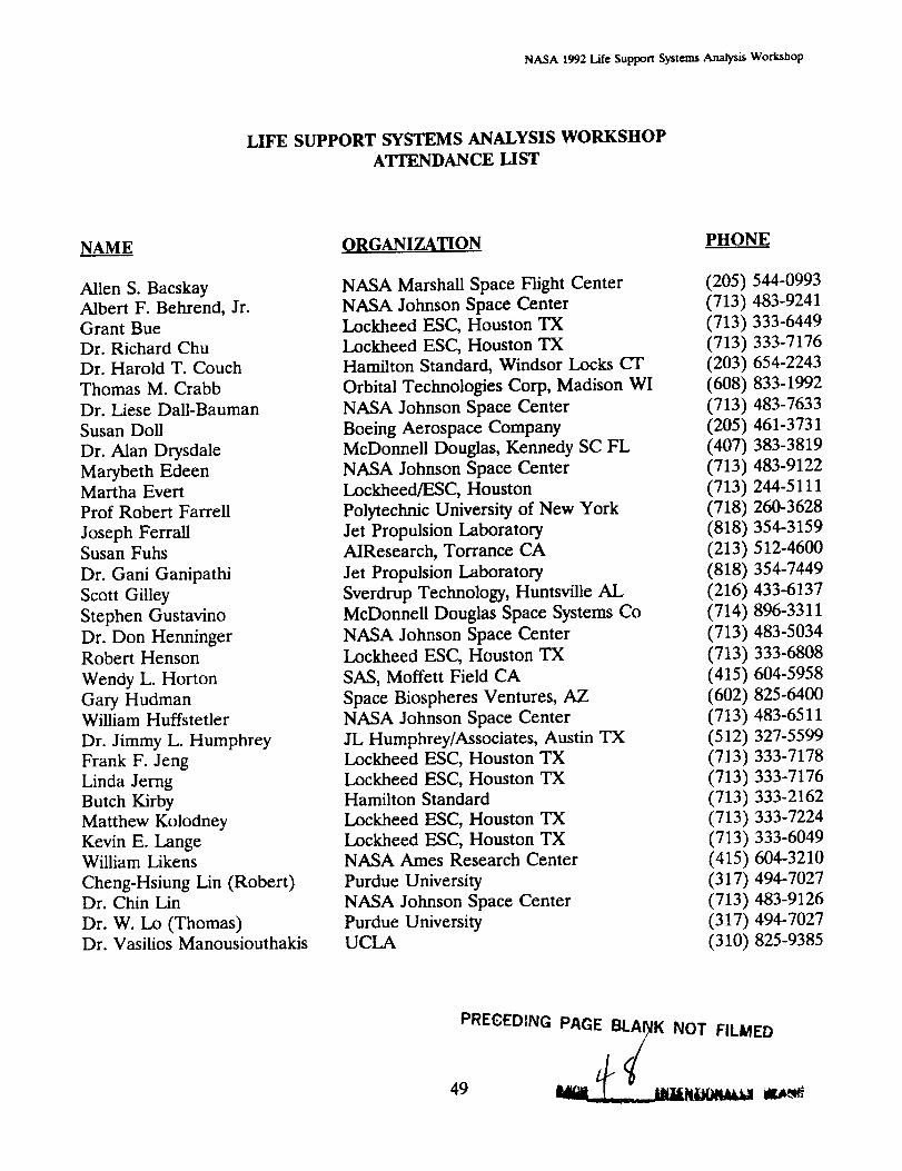
NASA 1992 Life Support Systems Analysis Workshop
LIFE SUPPORT SYSTEMS ANALYSIS WORKSHOP
ATTENDANCE LIST
NAME
Allen S. Bacskay
Albert F. Behrend, Jr.
Grant Bue
Dr. Richard Chu
Dr. Harold T. Couch
Thomas M. Crabb
Dr. Liese Dall-Bauman
Susan Doll
Dr. Alan Drysdale
Marybeth Edeen
Martha Evert
Prof Robert Farrell
Joseph FerraUSusan Fuhs
Dr. Gani Ganipathi
Scott Gilley
Stephen Gustavino
Dr. Don Henninger
Robert Henson
Wendy L. Horton
Gary HudmanWilliam Huffstetler
Dr. Jimmy L. Humphrey
Frank F. Jeng
Linda Jerng
Butch Kirby
Matthew Kolodney
Kevin E. LangeWilliam Likens
Cheng-Hsiung Lin (Robert)Dr. Chin Lin
Dr. W. Lo (Thomas)Dr. Vasilios Manousiouthakis
ORGANIZATION
NASA Marshall Space Flight Center
NASA Johnson Space Center
Lockheed ESC, Houston TX
Lockheed ESC, Houston TX
Hamilton Standard, Windsor Locks CT
Orbital Technologies Corp, Madison WI
NASA Johnson Space Center
Boeing Aerospace Company
McDonnell Douglas, Kennedy SC FL
NASA Johnson Space Center
Lockheed/ESC, Houston
Polytechnic University of New York
Jet Propulsion Laboratory
AIResearch, Torrance CA
Jet Propulsion Laboratory
Sverdrup Technology, Huntsville AL
McDonnell Douglas Space Systems Co
NASA Johnson Space Center
Lockheed ESC, Houston TX
SAS, Moffett Field CA
Space Biospheres Ventures, AZ
NASA Johnson Space Center
JL Humphrey/Associates, Austin TX
Lockheed ESC, Houston TX
Lockheed ESC, Houston TXHamilton Standard
Lockheed ESC, Houston TX
Lockheed ESC, Houston TXNASA Ames Research Center
Purdue University
NASA Johnson Space Center
Purdue UniversityUCLA
PHONE
(205) 544-0993
(713) 483-9241
(713) 333-6449
(713) 333-7176
(203) 654-2243
(608) 833-1992
(713) 483-7633
(205) 461-3731
(407) 383-3819
(713) 483-9122
(713) 244-5111
(718) 260-3628
(818) 354-3159
(213) 512-4600
(818) 354-7449
(216) 433-6137
(714) 896-3311
(713) 483-5034
(713) 333-6808
(415) 604-5958
(602) 825-6400
(713) 483-6511
(512) 327-5599
(713) 333-7178
(713) 333-7176
(713) 333-2162
(713) 333-7224
(713) 333-6049
(415) 604-3210
(317) 494-7027
(713) 483-9126
(317) 494-7027
(310) 825-9385
PRECEDING PAGE BL_K NOT FILMED
49 __....lt_lligklttt_ llfat.'_

NASA 1992 Life Support Systems Analysis Workshop
LIFE SUPPORT SYSTEMS ANALYSIS WORKSHOP
ATrENDANCE LIST
NAME
Kristin McCarthy
Dr. Patrick McCroskey
Carl McFadden
Andrew McGoughDr. Firooz Rasouli
Scott Ray
Daniel Reeves
Dr. Naresh Rohatgi
Stephen A. Rowe
Dr. Willy Sadeh
Dr. John Sager
Dr. Richard Seagrave
Dr. P.K. Seshan
Paul Shafer
Dr. Jack Spurlock
Paul Spurlock
Dr. Randy Stahl
Roger yon JouannaSassan Yerushalmi
ORGANIZATION
Rockwell International, Downey CA
The Dow Chemical Company, Midland MI
McDonnell Douglas, Houston TX
Aspen Technology, Houston TXChamberlain GARD
Aspen Technology
Boeing, Huntsville AL
Jet Propulsion Laboratory
AIResearch, Torrance CA
Colorado State University
NASA Kennedy Space Center
Iowa State University
Jet Propulsion Laboratory
Sterling SoftwareS&A Automated Systems, Inc.
S&A Automated Systems, Inc.
NASA JSC (currently at Texas A&M)
Boeing, Huntsville AL
Lockheed ESC, Houston TX
PHONE
(310) 922-3063
(517) 636-9826
(713) 335-4214
(713) 641-0940
(312) 647-9000
(713) 64 1-0940
(205) 561-5797
(818) 354-3073
(310) 323-9500
(303) 491-6057
(407) 853-5142
(515) 294-0518
(818) 354-7215
(415) 604-1420
(407) 750-8786
(407) 750-8786
(409) 845-9572
(205) 461-5792
(713) 333-6509
WORKSHOP SUPPORT
Marie L. Davis (Orbital Technologies Corporation)
Wynona Ellison (Lockheed ESC)
Barbara Angelo (Lockheed ESC)
5O

NASA 1992LifeSupportSystemsAnalysisWorkshop
APPENDIX C Original Working Group Presentations
C.1 Working Group 1: Systems Analysis Modeling and ExperimentalValidation/Verification
C.2 Working Group 2: Application of Systems Analysis to ProcessControl
C.3 Working Group 3: Integration of Component, Subsystem, System,and Mission Level Models
C.4 Working Group 4: Evaluation Criteria
51

NASA 1992 Life Support Systems Analysis Workshop
THIS PAGE INTENTIONALLY LEFT BLANK
52

NASA 1992 LLf¢ Support Systems Analysis Workshop
WORKING GROUP PARTICIPANTS
Systems Analysis Modelingand Experimental ValidationNerification
Chair: LIESE DALL-BAUMAN, NASA Johnson Space Center (713) 483-7633
NAME
Grant Bue
Susan Fuhs
Stephen Gustavino
Gary Hudman
Jimmy L. Humphrey
Frank F. Jeng
AFFILIATION
Lockheed
AiResearch
McDonnell Douglas
Space Biosphere Ven.
JL Humphrey & Assoc.
Lockheed
PHONE
713/333-6449
310/512-4600
714/896-3311
602/825-6400
512/327-5599
713/333-7178
Kevin E. Lange Lockheed 713/333-6049
Andrew McGough Aspen Technology 713/641-0940
Naresh Rohatgi JPL 818/354-3073
Firooz Rasouli ElectroCom GARD 708/647-3244
John C. Sager NASA KSC 407/750-5142
Jack M. Spurlock S&A Automated Sys 407/750-8786
PRE_ED{NG P,_CE BLANK NOT FILMED
53

NASA 1992 Life Support Systems Analysis Workshop
THIS PAGE INTENTIONALLY LEFT BLANK
54
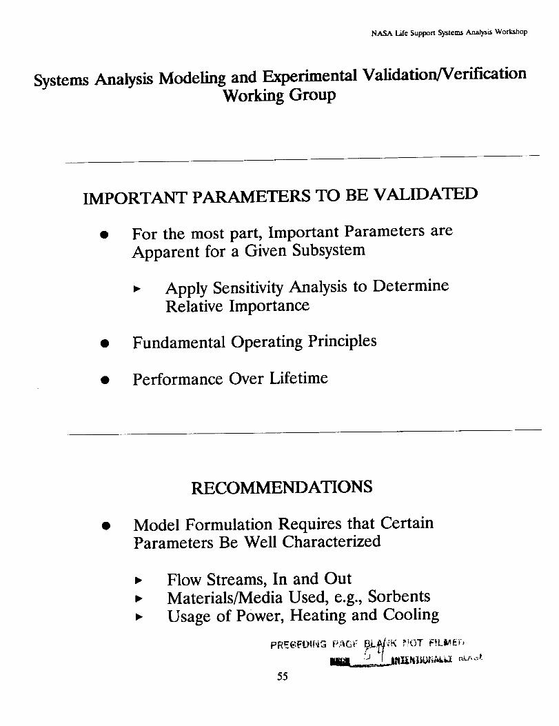
NASA Life Support Systems Analysis Workshop
Systems Analysis Modeling and Experimental Validation/VerificationWorking Group
IMPORTANT PARAMETERS TO BE VALIDATED
For the most part, Important Parameters areApparent for a Given Subsystem
Apply Sensitivity Analysis to DetermineRelative Importance
• Fundamental Operating Principles
• Performance Over Lifetime
RECOMMENDATIONS
Model Formulation Requires that CertainParameters Be Well Characterized
Flow Streams, In and Out
Materials/Media Used, e.g., SorbentsUsage of Power, Heating and Cooling
PREGEOI[,i_ P,-_Gi-- BLA/'_K _.!OT F!Li_,E¢,K
55
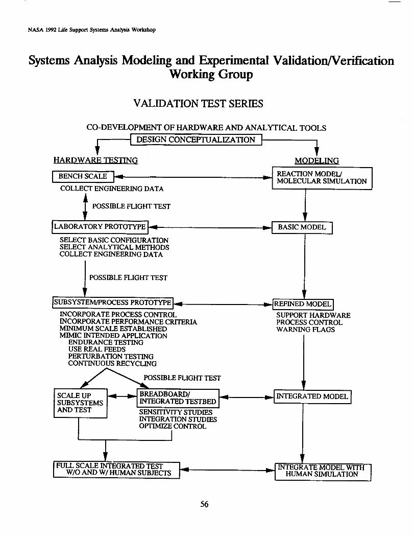
NASA 1992 Life Support Systems AJ_dysis Workshop
Systems Analysis Modeling and Experimental ValidationNerificafionWorking Group
VALIDATION TEST SERIES
CO-DEVELOPMENT OF HARDWARE AND ANALYTICAL TOOLS
HARDWARE TESTINQ
I BENCH SCALE I_.,
COLLECT ENGINEERING DATA
I POSSIBLE FLIGHT TEST
[LABORATORY PROTOTYPE I_'_
A AL AL .OD COLL TE O E ,,ODATA
POSSIBLE FLIGHT TEST
ISUBSYSTEM/PROCESS PROTOTYPE I_
INCORPORATE PROCESS CONTROLINCORPORATE PERFORMANCE CRITERIAMINIMUM SCALE ESTABLISHEDMIMIC INTENDED APPLICATION
ENDURANCE TESTINGUSE REAL FEEDSPERTURBATION TESTINGCONTINUOUS RECYCLING
POSSIBLE FLIGHT TEST
SCALE UPSUBSYSTEMSAND TEST
I
FULL SCALE INTEGRATED TESTW/O AND W/HUMAN SUBIECTS
iv--_ BREADBOARD/ ]INTEGRATED TESTBED
SENSITIVITY STUDIESINTEGRATION STUDIESOPTIMIZE CONTROL
I
MODELING
,.. ] REACTION MODEL/
v I MOLECULAR SIMULATION
lvt'-I BASICMODEL ]
v_--IREFINED MODEL ]
SUPPORT HARDWAREPROCESS CONTROLWARNING FLAGS
r
,,..._I INTEGRATED MODEL [I
-Ir
INTEGRATE MODEL WITH IHUMAN SIMULATION I
56
NASA Life Support Systems Analysis Workshop
Systems Analysis Modeling and Experimental Validation/VerificationWorking Group
RECOMMENDATIONS FORVALIDATION TEST SERIES
Establish Standardized Feed Compositions for all
Components at Each Level of Testing
Establish Minimum Scale Size for
Subsystem/Process Prototype
Conduct Flight Testing, if necessary, at EarliestPossible Developmental Stage
57
NASA 1992I._¢SupportSystcm,sAnaJy_s Workshop
Systems Analysis Modeling and Experimental Validation/VerificationWorking Group
ESTABLISH BASELINE
"Real" Application Conditions, e.g., Duration ofTest
Well Defined Feed Compositions, including TraceContaminants
• Minimum Scale
• Operating Conditions (Environment)
• Product Specifications
58
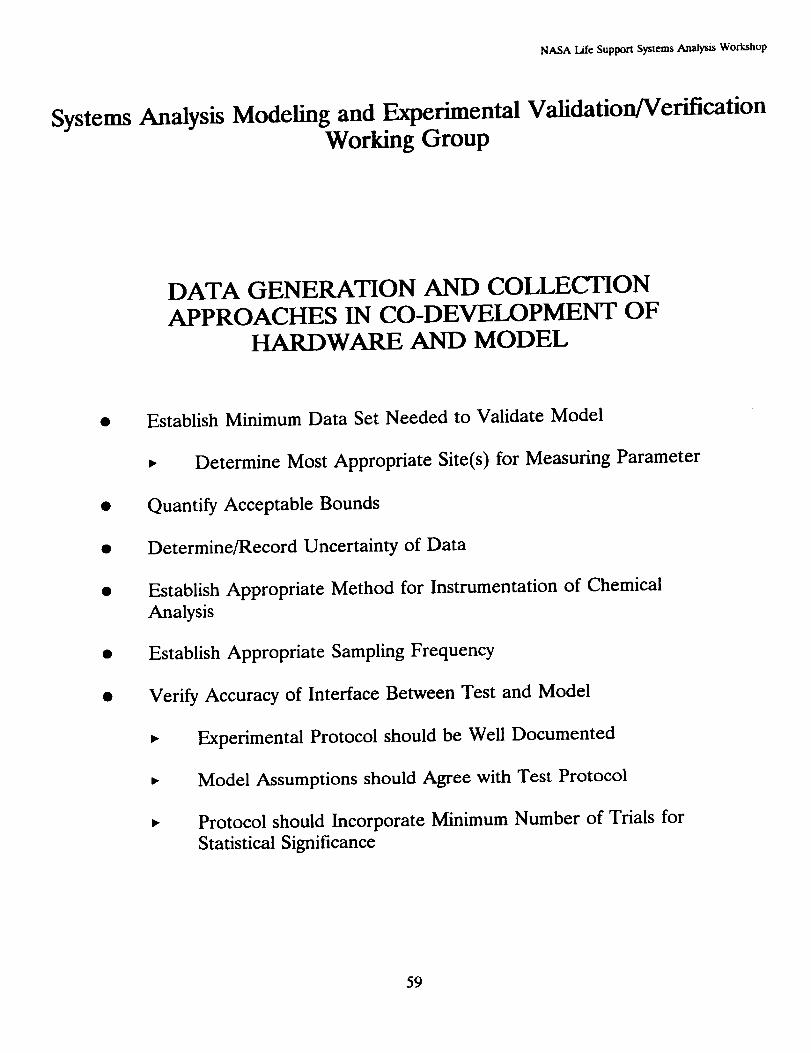
NASA Life Support Systems Analysis Workshop
Systems Analysis Modeling and Experimental Validation/VerificationWorking Group
DATA GENERATION AND COLLECTION
APPROACHES IN CO-DEVELOPMENT OFHARDWARE AND MODEL
Establish Minimum Data Set Needed to Validate Model
• Determine Most Appropriate Site(s) for Measuring Parameter
Quantify Acceptable Bounds
Determine/Record Uncertainty of Data
Establish Appropriate Method for Instrumentation of Chemical
Analysis
Establish Appropriate Sampling Frequency
Verify Accuracy of Interface Between Test and Model
• Experimental Protocol should be Well Documented
• Model Assumptions should Agree with Test Protocol
• Protocol should Incorporate Minimum Number of Trials for
Statistical Significance
59

NASA 1992 Life Support Systems Analysis Workshop
Systems Analysis Modeling and Experimental ValidationNerificationWorking Group
INFORMATION NEEDED FORSCALE-UP OF MODEL
• Characterize Each Component in System
• Dimensioned Engineering Drawings
• Throughputs
• Construction Materials
• Use Experience Base
Determine Nonlinearities and Boundaries in
Process Scaling
60
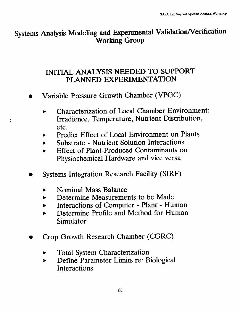
NASA Lilt Support Systems Analysis Workshop
Systems Analysis Modeling and Experimental Validation/VerificationWorking Group
INITIAL ANALYSIS NEEDED TO SUPPORTPLANNED EXPERIMENTATION
• Variable Pressure Growth Chamber (VPGC)
Characterization of Local Chamber Environment:
Irradience, Temperature, Nutrient Distribution,etc.Predict Effect of Local Environment on PlantsSubstrate - Nutrient Solution InteractionsEffect of Plant-Produced Contaminants on
Physiochemical Hardware and vice versa
Systems Integration Research Facility (SIRF)
Nominal Mass BalanceDetermine Measurements to be Made
Interactions of Computer - Plant- HumanDetermine Profile and Method for HumanSimulator
Crop Growth Research Chamber (CGRC)
Total System CharacterizationDefine Parameter Limits re: BiologicalInteractions
61
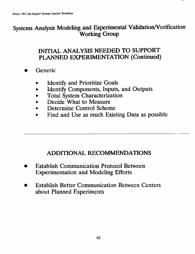
NASA 1992 Life Support Systems Analysis Workshop
Systems Analysis Modeling and Experimental Validation/VerificationWorking Group
INITIAL ANALYSIS NEEDED TO SUPPORT
PLANNED EXPERIMENTATION (Continued)
• Generic
Identify and Prioritize GoalsIdentify Components, Inputs, and OutputsTotal System CharacterizationDecide What to MeasureDetermine Control Scheme
Find and Use as much Existing Data as possible
ADDITIONAL RECOMMENDATIONS
Establish Communication Protocol Between
Experimentation and Modeling Efforts
Establish Better Communication Between Centers
about Planned Experiments
62
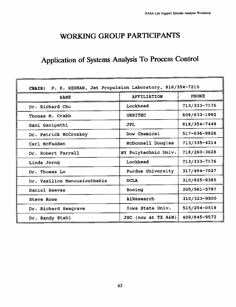
NASA Life Suppon Systems Analysis Workshop
WORKING GROUP PARTICIPANTS
Application of Systems Analysis To Process Control
CHAIR: P. K. SESHAN, Jet Propulsion Laboratory, 818/354-7215
NAME AFFILIATION PHONE
Dr. Richard Chu Lockheed 713/333-7176
Thomas M. Crabb ORBITEC 608/833-1992
Gani Ganipathi JPL 818/354-7449
Dr. Patrick McCroskey Dow Chemical 517-636-9826
Carl McFadden McDonnell Douglas 713/335-4214
Dr. Robert Farrell NY Polytechnic Univ. 718/260-3628
Linda Jerng Lockheed 713/333-7176
Dr. Thomas Lo Purdue University 317/494-7027
Dr. Vasilios Manousiouthakis UCLA 310/825-9385
Daniel Reeves Boeing 205/561-5797
Steve Rowe AiResearch 310/323-9500
Dr. Richard Seagrave Iowa State Univ. 515/294-0518
Dr. Randy Stahl JSC (now at TX A&M) 409/845-9572
63

NASA 1992LifeSupportSystemsAnalysisWorkshop
THIS PAGE INTENTIONALLY LEFT BLANK
64
_ tare sapln_ syue_ Aeatym wo,t_op
APPLICATION OF SYSTEMS ANALYSIS TO PROCESS CONTROLWORKING GROUP
TOPIC/ISSUE: List All Controlled Variables
STATEMENT OF PROBLEM:
The number of measurements needed for control is highly dependent on the mission
duration and the degree of closure. Key measurement parameters of control need to be
identified and defined as a function of degree of life support system closure.
DESCRIPTION OF STATE OF THE ART:
For Shuttle: CO2, Humidity, Temperature, and Pressure
For Space Station: 02, H20 (both vapor and liquid), CO 2, temperature, and pressure
(reported 5 measurements currently tracked by the Space Station
Program for developing control algorithms).
OBSERVATIONS:
The general consensus in identifying the control parameters is to first identify and track
by computer: (1) the number of desirable chemical species and (2) all possible toxins
and/or undesirable by-products produced from the individual subsystems during the
technology development stage. Adhering to the quality standards of certain equipment
(i.e., fuel cell water) can also dictate the number and t_es of chemical species to betracked.
RECOMMENDATIONS FOR RESEARCH AND TECHNOLOGY DEVELOPMENT:
Minimum variables for short-duration mission:
• Technology specific species
• Toxins to crew quarters
CO2, n20 , 02, N2, and Pressure
• For long-duration mission: Number of variables is highly dependent on the missionduration.
65
PRE6EDING PAGE E_LANK NOT FILMED

_ supi_rt _ _m_/m wor_
APPLICATION OF SYSTEMS ANALYSIS TO PROCESS CONTROLWORKING GROUP
TOPIC/ISSUE: Control Methodology
STATEMENT OF PROBLEM: Selection of Control Methodology
DESCRIPTION OF STATE OF THE ART:
Space Station Freedom: 1553 serial interface
- connected to: 6 MDMs
2 SDPs
3 386/486s
w/firmware controllers
• Chevron E1 Segundo Refinery: block decentralization
OBSERVATIONS:
One commented that a totally centralized control system is the best way to achieve
maximum performance, provided that there is no limitation on the computer resources.
Another commented that a distributed system is the most feasible methodology that
permits systems flexibilities (e.g., diagnostic purposes) and may reduce computer resource
requirements. It was generally agreed that a high-fidelity integrated model is the top
priority for off-line stimulating and characterizing behavior of the systems. One noted
that, during the development of one single subsystem, 80 percent of the control
algorithms are devoted to fault detection, safeguarding the equipment, and process
performance.
RECOMMENDATIONS FOR RESEARCH AND TECHNOLOGY DEVELOPMENT:
• Develop high-fidelity integrated model
• Start from simplest control method and add degrees of sophistication as needed
• For a non-linear system: use non-linear model predictive method
For a highly-interactive system: use state-space linear system method
• Total centralized control methodology results in better control, but is not feasible
for large systems
66
NmSAUteSeppmSr_mmAea_isWoaahap
APPLICATION OF SYSTEMS ANALYSIS TO PRO_ CONTROL
WORKING GROUP
TOPIC/ISSUE: Dynamic Simulation Tool
STATEMENT OF PROBLEM:
What dynamic simulation model is best suited for life support systems?
DESCRIPTION OF STATE OF THE ART:
GENERAL PURPOSE CHEMICAL PROCESS
ACSL
MatrixX/SYSTEM BUILD
MATLAB/SIMULAB
CACSD
XANALOG
Others
SPEEDUP
EASY5
Japanese ApproachOthers
OBSERVATIONS:
One participant favored pull-down, menu-driven interface to the simulation computer.
Another commented that a general purpose computer that allowed a high degree of user
programmable capabilities is absolutely necessary. One commented that SPEEDUP,
which is equation driven, may not predict adequate initial guesses and has limited user
programmable capability. However, SPEEDUP has the advantage of built-in dynamic
modeling and control capabilities. Simulation tools listed under the General Purpose
category require massive modeling efforts as they are offered as a "shell" only to dynamic
modeling. One suggested that the rigorous dynamic modeling would be the first and
good approach to controlling non-linear, interactive systems.
RECOMMENDATION FOR RESEARCH AND TECHNOLOGY DEVELOPMENT:
Development of a more open and adaptive dynamic simulation tool is highly desirable.
67
_ tat.saatmas',/_nm.'um_ wG_ta_,
APPLICATION OF SYSTEMS ANALYSIS TO PROCESS CONTROLWORKING GROUP
TOPIC/ISSUE: Control Technology Development
STATEMENT OF PROBLEM:
What are the benefits of increasing the sophistication of control technology within the life
support system?
OBSERVATIONS:
Potential benefits of highly sophisticated control algorithms include, but are not limited
to: increased safety measure, reduction in crew maintenance time, reduction in buffer
size, utility savings, possible weight savings (increased performance). However, risk
associated with a system that relies highly on the control system must be properly
assessed. Subjects on the stability and resiliency or degree of robustness of any complex
control system should be fully investigated.
RECOMMENDATIONS FOR RESEARCH AND TECHNOLOGY DEVELOPMENT:
Conduct quantitative analyses of trade-offs and sensitivities of control system
complexity and sophistication with respect to life support system performance and
reliability.
• Determine minimum requirements of control system approach for regenerative life
support systems.
68

l_LSA Li_ Sanm_ S,/ramm,_a_m Wottanop
APPLICATION OF SYSTEMS ANALYSIS TO PROCESS CONTROLWORKING GROUP
Mission
Length
(Days)
lo00
I00
10
] trace elements
] integrated PC/BIO
1/
,,_b%,o°q / non-linearmany species/ stochastic inputs
_J
linear, steady-state, rule-basedregular inputs
PC-basedmulti-species
model-based dynamics
v
I0
Control System Complexity
(# Parameters)
IO0
MISSION LENGTH vs. CONTROL SYSTEMS COMPLEXITY
69
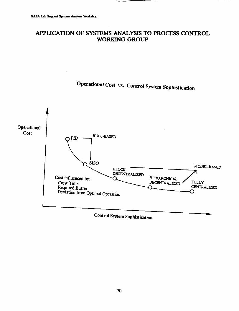
tUlSA Li_ S_ma Sr_ tum_ Wottt_
APPLICATION OF SYSTEMS ANALYSIS TO PRO_ CONTROLWORKING GROUP
Operational Cost vs. Control System Sophistication
OperationalCost RULE-BASED
__O__ BLOCK MODEL-BASED
C_st_fl?_cedby: __'__R_IT_D /FULLYCENTR.ALLZED
Required Buffer O
Deviation from Optimal Operation
lb...._v
Control System Sophistication
7O
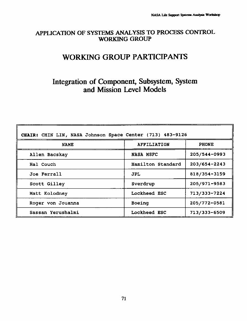
APPLICATION OF SYSTEMS ANALYSIS TO PROCF__S CONTROL
WORKING GROUP
WORKING GROUP PARTICIPANTS
Integration of Component, Subsystem, Systemand Mission Level Models
CHAIR: CHIN LIN, NASA Johnson Space Center (713) 483-9126
NAME AFFILIATION PHONE
Allen Bacskay NASA MSFC 205/544-0993
Hal Couch Hamilton Standard 203/654-2243
Joe Ferrall JPL 818/354-3159
Scott Gilley Sverdrup 205/971-9583
Matt Kolodney Lockheed ESC 713/333-7224
Roger von Jouanna Boeing 205/772-0581
Sassan Yerushalmi Lockheed ESC 713/333-6509
71

NASA 1992 Life Support Systems Analysis Workshop
THIS PAGE INTENTIONALLY LEFT BLANK
72
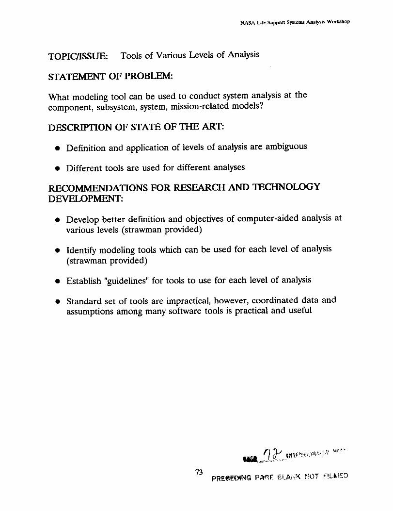
NASA L./f¢ Supporli Syslems Analysis Workshop
TOPIC/ISSUE: Tools of Various Levels of Analysis
STATEMENT OF PROBLEM:
What modeling tool can be used to conduct system analysis at the
component, subsystem, system, mission-related models?
DESCRIFHON OF STATE OF THE ART:
• Definition and application of levels of analysis are ambiguous
• Different tools are used for different analyses
RECOMMENDATIONS FOR RESEARCH AND TECHNOLOGY
DEVELOPMENT:
• Develop better definition and objectives of computer-aided analysis at
various levels (strawman provided)
• Identify modeling tools which can be used for each level of analysis
(strawman provided)
• Establish "guidelines" for tools to use for each level of analysis
• Standard set of tools are impractical, however, coordinated data and
assumptions among many software tools is practical and useful
73pRE_,,EOtNG i;._¢_._E _l_A.i'--."g ,_.!OT f'Ll_';£_

NASA l_.ile Support Systems Analysis Workshop
INTEGRATION OF COMPONENT, SUBSYSTEM, SYSTEM AND
MISSION LEVEL MODELS WORKING GROUP
LEVEL
2
3
4
DEFINITION
TRADE OFF ANALYSIS BASED ON
MISSION REQUIREMENTS ANDPOTENTIAL TECHNOLOGY
CANDIDATES
CONCEPTUAL FLOWSHEET
ANALYSIS FOR INTEGRATED LSSAND SIZING OF MAJORFUNCTIONAL COMPONENTS
SYSTEM DESIGN VERIFICATION
FOR MEETING MISSION
REQUIREMENT AND SYSTEMOPERATION SUPPORT
DETAILED PHENOMENOLOGICALANALYSIS
ANALYSIS FOR CONTROL ANDOPERATION
USE
TECHNOLOGY
ASSESSMENT
PRE-PHASE A _ PHASE B
(MISSION DEFINITION)
PHASE C/D _ OPERATION
DETAILED PERFORMANCE
MAPPING, HARDWARE
VERIFICATION, TESTSUPPORT
ASSESMENT AND DESIGN OF
CONTROL SYSTEM
74
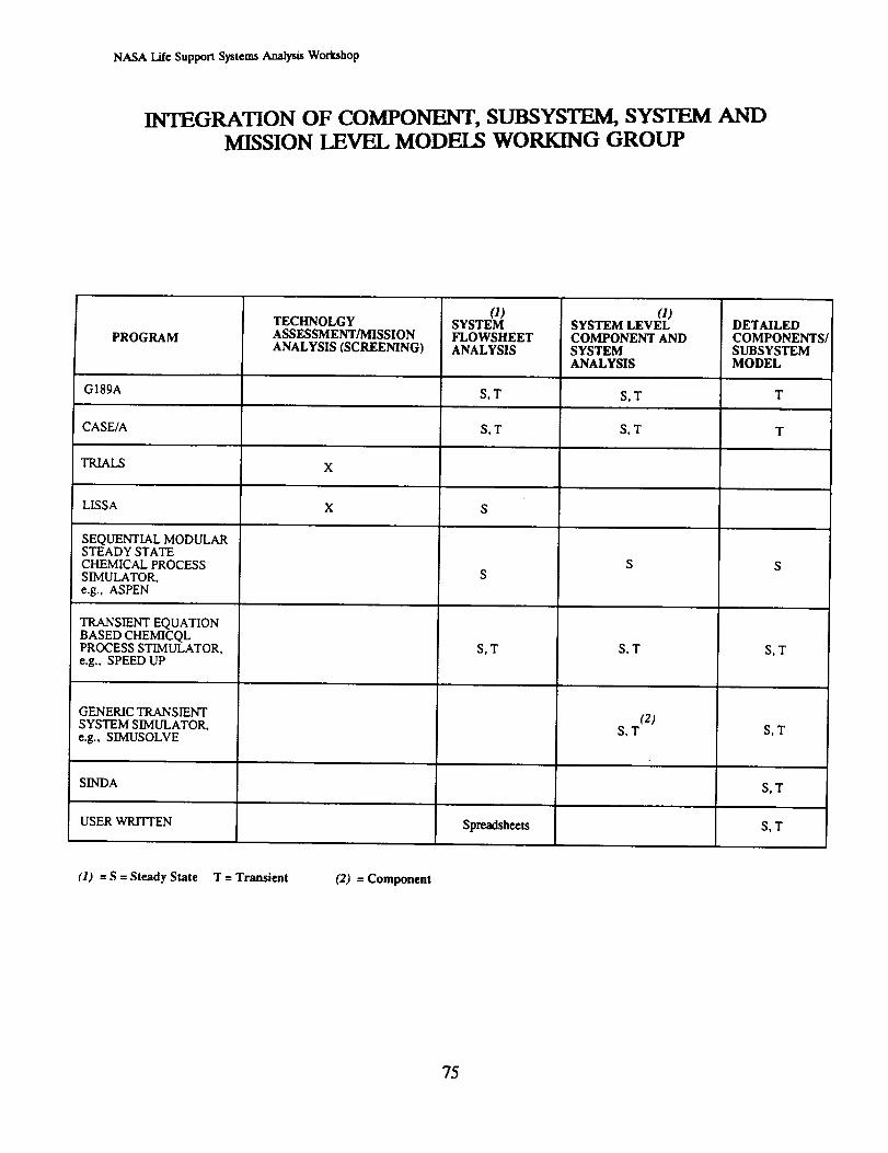
NASA Lile Support Systems Analysis Workshop
INTEGRATION OF COMPONENT, SUBSYSTEM, SYSTEM AND
MISSION LEVEL MODELS WORKING GROUP
PROGRAM
TECHNOLGYASSESSMENT/MISSIONANALYSIS (SCREENING)
G189A
CASE/A
TRIALS X
LISSA
SEQUENTIAL MODULARSTEADY STATECHEMICAL PROCESSSIMULATOR,e.g., ASPEN
TRANSIENT EQUATIONBASED CHEMICQLPROCESS STIMULATOR,e.g., SPEED UP
GENERIC TRANSIENT
SYSTEM SIMULATOR,e.g., SIMUSOLVE
SINDA
USER WRITTEN
X S
SYSTEMFLOWSHEETANALYSIS
_)SYSTEM LEVELCOMPONENT ANDSYSTEMANALYSIS
S,T S,T
S,T S,T
S
S,T
Spreadsheets
S,T
(2)S,T
DETAILEDCOMPONENTSJSUBSYSTEMMODEL
T
T
S,T
S,T
S,T
S,T
(1) = S = Steady State T = Transient (2) = Component
75

NASA Life Support Systems Analysis Workshop
INTEGRATION OF COMPONENT, SUBSYSTEM, SYSTEM ANDMISSION LEVEL MODELS WORKING GROUP
TOPIC/ISSUE: Integration of Various Levels of Analysis
STATEMENT OF PROBLEM:
What interface guidelines and standards are necessary and appropriate to
allow integration of modeling output or directly interfacing analyticalmodels?
DESCRIFHON OF STATE OF THE ART:
• Models at various levels are mostly developed independently
• Very little flow of data and information among models
RECOMMENDATIONS FOR RESEARCH AND TECHNOLOGY
DEVELOPMENT:
• Establish common (non-conflicting) assumptions among models
• Establish standard physical/chemical data for common use by models
• Regular update of models at various levels with technology advances
• When defining requirements for model development, provide
input/output requirements for flow of information between models
(see strawman requirements chart)
• Improve flow of information throughout various levels
• Identify limitations, assumptions, and constraints for models at all levels
76
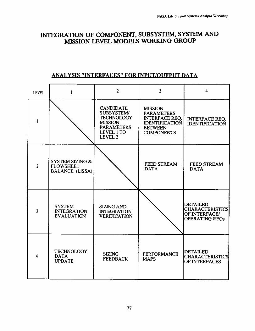
NASA lAIe Support Systems Analysis Workshop
INTEGRATION OF COMPONENT, SUBSYSTEM, SYSTEM AND
MISSION LEVEL MODELS WORKING GROUP
ANALYSIS "INTERFACES" FOR INPUT/OUTPUT DATA
LEVEL
SYSTEM SIZING &FLOWSHEET
BALANCE (LiSSA)
SYSTEMINTEGRATIONEVALUATION
TECHNOLOGYDATAUPDATE
CANDIDATE
SUBSYSTEM/TECHNOLOGYMISSIONPARAMETERSLEVEL 1 TOLEVEL 2
SIZING ANDINTEGRATIONVERIFICATION
MISSIONPARAMETERS
INTERFACE REQ.IDENTIFICATIONBETWEENCOMPONENTS
FEED STREAMDATA
SIZINGFEEDBACK
PERFORMANCEMAPS
INTERFACE REQ.IDENTIFICATION
FEED STREAMDATA
DETAILEDCHARACTERISTICSOF INTERFACE/
OPERATING REQs
DETAILEDCHARACTERISTICSOF INTERFACES
77

NASA Life Support Systems Analysis Workshop
INTEGRATION OF COMPONENT, SUBSYSTEM, SYSTEM ANDMISSION LEVEL MODELS WORKING GROUP
THIS PAGE INTENTIONALLY LEFT BLANK
78

NASA Life Support Systems Analysis Workshop
WORKING GROUP PARTICIPANTS
Evaluation Criteria
Chair: WILLIAM LIKENS, NASA Ames Research Center (415) 604-32210
NAME AFFILIATION PHONE
Susan Doll Boeing, Huntsville 205/461-3731
Alan Drysdale McDonnell Douglas 407/383-3819
Marybeth Edeen NASA JSC 713/483-9122
Martha Evert Lockheed ESC 713/244-5111
Robert Henson Lockheed ESC 713/333-6808
Kristin McCarthy Rockwell Int'l 310/922-3063
Willy Sadeh Colorado State Univ. 303/491-2001
Paul Sharer Lockheed ESC 713/333-6808

NASA 1992 Life Support Systems Analysis Workshop
THIS PAGE INTENTIONALLY LEFT BLANK
80
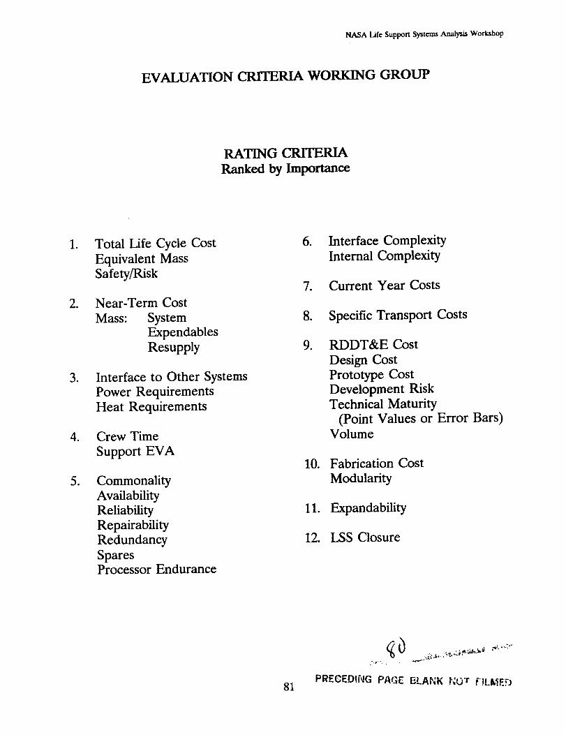
NASA Life Support Systems Analysis Workshop
EVALUATION CRITERIA WORKING GROUP
RATING CRITERIA
Rankexl by Importance
.
*
*
g
.
Total Life Cycle Cost
Equivalent Mass
Safety/Risk
Near-Term Cost
Mass: System
Expendables
Resupply
Interface to Other Systems
Power RequirementsHeat Requirements
Crew Time
Support EVA
Commonality
Availability
Reliability
Repairability
Redundancy
SparesProcessor Endurance
,
.
.
,
Interface Complexity
Internal Complexity
Current Year Costs
Specific Transport Costs
RDDT&E Cost
Design Cost
Prototype Cost
Development Risk
Technical Maturity
(Point Values or Error Bars)Volume
10. Fabrication Cost
Modularity
11. Expandability
12. LSS Closure
,)
PRECEDING PAGE ELANK NOT FtLlt,'_ED81
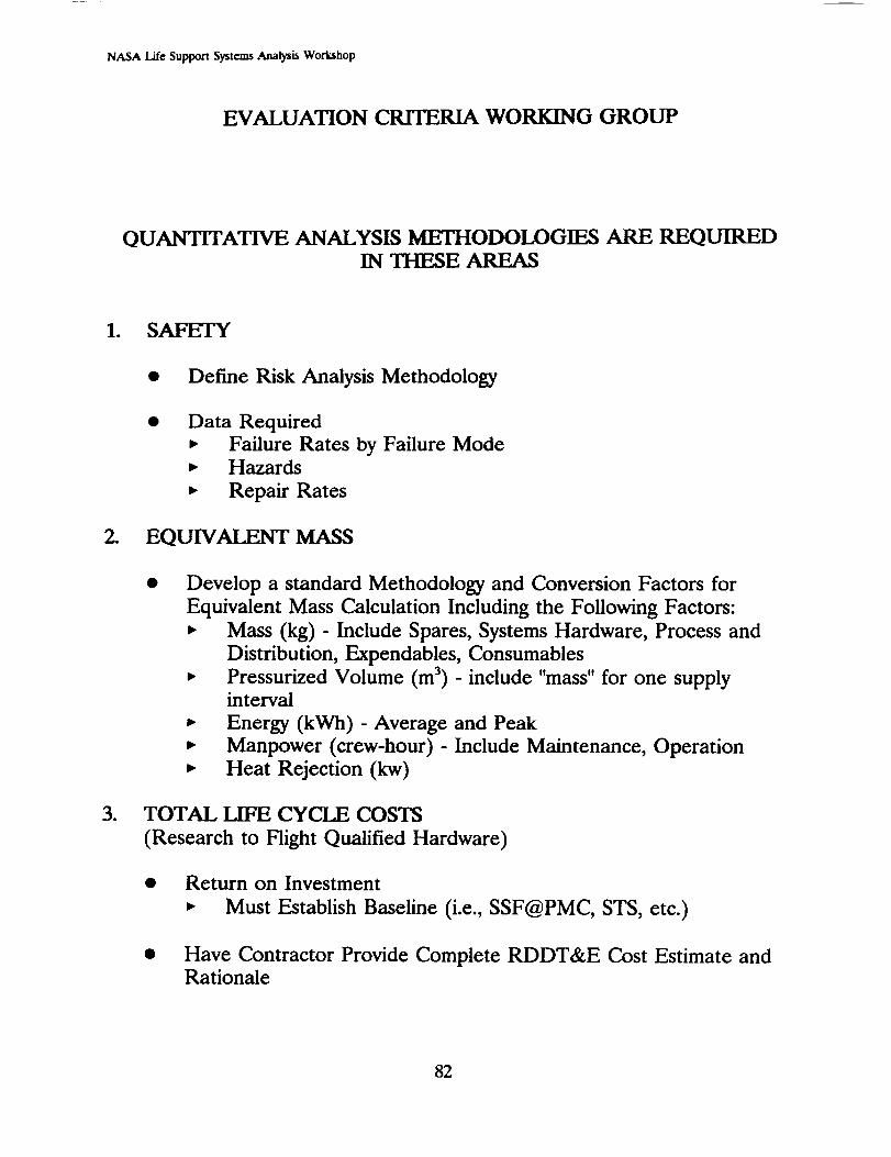
NASA Life Support Systems Analysis Workshop
EVALUATION CRITERIA WORKING GROUP
QUANTITATIVE ANALYSIS METHODOLOGIF__ ARE REQUIREDIN THESE AREAS
1. SAFETY
o
.
• Define Risk Analysis Methodology
Data Required
,, Failure Rates by Failure Mode• Hazards
• Repair Rates
EQU1V MASS
Develop a standard Methodology and Conversion Factors for
Equivalent Mass Calculation Including the Following Factors:
,. Mass (kg) - Include Spares, Systems Hardware, Process and
Distribution, Expendables, Consumables
• Pressurized Volume (m 3) - include "mass" for one supplyinterval
• Energy (kWh) - Average and Peak
• Manpower (crew-hour) - Include Maintenance, Operation
• Heat Rejection (kw)
TOTAL LIFE CYCLE COSTS
(Research to Hight Qualified Hardware)
Return on Investment
• Must Establish Baseline (i.e., SSF@PMC, STS, etc.)
Have Contractor Provide Complete RDDT&E Cost Estimate andRationale
82
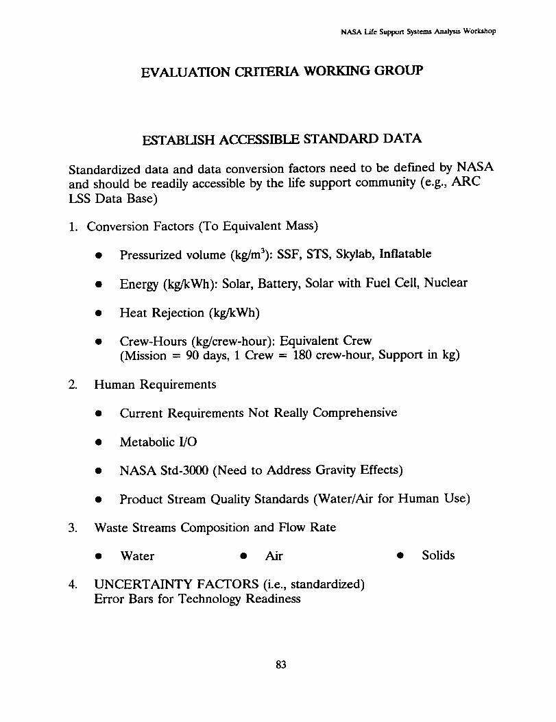
NASA Life Support Systems Analysis Workshop
EVALUATION CRITERIA WORKING GROUP
ESTABLISH ACCESSIBLE STANDARD DATA
Standardized data and data conversion factors need to be defined by NASA
and should be readily accessible by the life support community (e.g., ARC
LSS Data Base)
1. Conversion Factors (To Equivalent Mass)
• Pressurized volume (kg/m3): SSF, STS, Skylab, Inflatable
• Energy (kg/kWh): Solar, Battery, Solar with Fuel Cell, Nuclear
• Heat Rejection (kg/kWh)
• Crew-Hours (kg/crew-hour): Equivalent Crew
(Mission = 90 days, 1 Crew = 180 crew-hour, Support in kg)
2. Human Requirements
°
.
Current Requirements Not Really Comprehensive
Metabolic I/O
NASA Std-3000 (Need to Address Gravity Effects)
Product Stream Quality Standards (Water/Air for Human Use)
Waste Streams Composition and Flow Rate
• Water • Air
UNCERTAINTY FACTORS (i.e., standardized)
Error Bars for Technology Readiness
• Solids
83
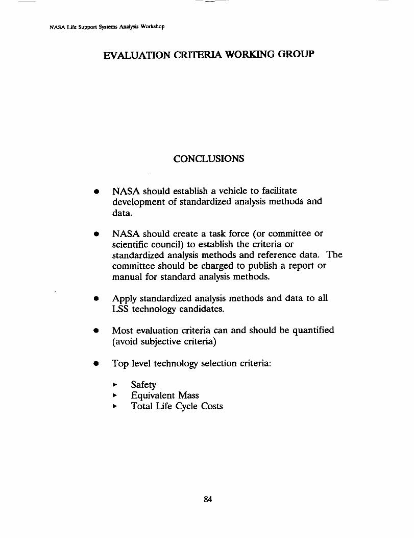
NASA Life Support Systems Analysis Workshop
EVALUATION CRITERIA WORKING GROUP
CONCLUSIONS
NASA should establish a vehicle to facilitate
development of standardized analysis methods anddata.
NASA should create a task force (or committee or
scientific council) to establish the criteria or
standardized analysis methods and reference data. Thecommittee should be charged to publish a report or
manual for standard analysis methods.
Apply standardized analysis methods and data to all
LSS technology candidates.
Most evaluation criteria can and should be quantified
(avoid subjective criteria)
• Top level technology selection criteria:
Safety
Equivalent Mass
Total Life Cycle Costs
84
NASA 1992 Life Support Systems Analysis Workshop
APPENDIX D Workshop Report Distribution
85

NASA 1992 Life Support Systems Anal_ Workshop
THIS PAGE INTENTIONALLY LEFT BLANK
DISTRIBUTION
Dr. Mel Averner
Code SBR
NASA HeadquartersWashington, D.C. 20546
Grant BueLockheed2400 NASA Road 1, C70Houston, TX 77058-3799
Dr. Alan DrysdaleMcDonnell DouglasP.O. Box 21233
Kennedy Space Ctr, FL 32815
Allen S. BacskayCode ED62, Bldg 'I"285NASA MSFC
MSFC, AL 35812
Mark G. BallinCode SAS, M/S 239-8NASA Ames Research Center
Moffett Field, CA 94035
Dr. W.B. Bedwell
Allied Signal50 E. Algonquin RdDes Plaines, IL 60017-5016
Albert F. Behrend, Jr.NASA Johnson Space Center2101 NASA Road 1CODE EC3
Houston, TX 77058
Dr. Larry BieglerCarnegie Mellon UniversityDougherty HallPittsburgh, PA 15213
Dr. Attilio BisioBox 1367Mountainside, NJ 07092
Joan F. Brennecke
University of Notre DameDept of Chemical EngineeringNotre Dame, IN 46556
Dr. Paul BuchananCode MD
NASA Kennedy Space CenterKSC, FL 32899
Mr. Norm Chaffee
NASA Johnson Space Center2101 NASA Road 1CODE XEHouston, TX 77058
Richard ChuLockheed ESCCode 0702400 NASA Road 1Houston, TX 77058
Ms. Carolyn CooleyMartin Marietta Civil & SpaceCommunicationsP.O. Box 179, M/S DC8001Denver, CO 80201
Dr. Harold T. CouchHamilton StandardOne Hamilton Road
Windsor Locks, CT 06096-1010
Mr. Robert DaLee
McDonnell Douglas689 Discovery Drive, Mail Code 12C'3Huntsville, AL 35806
Dr. Liese Dall-BaumanNASA JSC2101 NASA Road 1Code EC
Houston, TX 77058
Dr. Glenn DissingerAspen Technology7007 Gulf Freeway, Ste 133Houston, 'IX 77087
Ms. Susan Doll
Boeing Aerospace CompanyM/S JX-23P.O. Box 240002Huntsville, AL 35824-6402
Marybeth EdeenNASA Johnson Space Center2101 NASA Road 1Code EC'7
Houston, TX 77058
Mr. Wit Ellis
NASA Johnson Space Center2101 NASA Road 1, Code ECHouston, TX 77058
Peggy L. EvanichNASA HeadquartersOASTCode RSR
Washington, DC 20546
Larry EvansAspen Technologies, Inc.251 Vassar Street
Cambridge, MA 02139
Martha EvertLockheeA/ESC2400 NASA Road 1MC-C44
Houston, TX 77058
Dr. Robert Farrell
Polytechnic University333 Jay StreetBrooklyn, NY 11201
Mr. Jeffrey FaszczaHamilton StandardMS 1A2 W66One Hamilton Road
Windsor Locks, CT 06096
Dr. Michael FehlingTerman Engineering CenterStanford UniversityStanford, CA 94305-4025

Mr.JosephFerrallMAIL CODE 125-224
Jet Propulsion Laboratory4800 Oak Grove Drive
Pasadena, CA 91109
Mr. John Fisher
Code SAR, M/S 239-11NASA Ames Research Center
Moffett Field, CA 94035
Dr. Edwin ForceCode SANASA Ames Research Center
Moffett Field, CA 94035
Ms. Susan FulLs
AIResearch/Allied SignalDept 93190/T-41P.O. Box 2960Torrance, CA 90509-2960
Oani B. OanipathiJet Propulsion Lab4800 Oak Grove Dr
M/S 125-224Pasadena, CA 91109
Mr. Scott GilleySverdrup Technology620 Discovery DriveHuntsville, AL 35806
Mr. Stephen GustavinoMcDonnell Douglas5301 Bolsa AvenueMail Code 17-B
Huntington Beach, CA 92647
Dr. Donald HenningerNASA Johnson Space Center2101 NASA Road 1Code EC3
Houston, TX 77058
Robert HensonLockheed ESC2400 NASA Road 1Code C70
Houston, TX 77058
Mr. Joseph HomaHamilton StandardOne Hamilton Road
M/S 1A-2-W66
Windsor Locks, CT 06096
Wendy L HortonSAS
M/S 239--8Moffett Field, CA 94035-1000
Gary HudrnanSpace Biospheres VenturesP.O. Box 689Oracle, AZ 85623
William HuffstetlerMail Code IA
NASA Johnson Space CenterHouston, 'IX 77058
Dr. Jimmy L. HumphreyJL Humphrey & Associates3605 Needles DriveAustin, 'IX 78746
Frank F. JengLockheed ESCESPO, C70P.O. Box 53561
Houston, TX 77258-8561
Linda JerngLockheed2400 NASA Road 1
Houston, TX 77058-3799
Butch KirbyHamilton Standard
2200 Space Park #I00Houston, TX 77058
Dr. William KnottNASA KSCCode MD-RES
Hangar L, Room 218Kennedy Six: Ctr, FL 32899
Mr. Matthew KolodneyLockheed EngineeringM/C C702400 NASA Road 1
Houston, TX 77058
Mr. Dick LamparterCode SARNASA Ames Research CenterM/S 239-11
Moffett Field, CA 94035
Kevin E. Lange
Lockheed EngineeringM/C C702400 NASA Road 1
Houston, TX 77058
Dr. Norman Li
Allied Signal50 E. Algonquin RdDes Plaines, IL 60017
William LikensNASA Ames Research Center
Code SAS, M/S 239-8Moffett Field, CA 94035
Dr. Chin Lin
NASA Johnson Space CenterCode EC72101 NASA Road 1
Houston, 'IX 77058
Mr. Robert Lin
Purdue University1295 Potter BuildingWest Lafayette, IN 47907
Dr. Waihung (Thomas) LoLab of Renewable Resources EngrgPurdue UniversityLorre/Potter Center, Rm 220West Lafayette, IN 47907
Mr. Allen MacKnightAIResearch - LA Division2525 W. 19th StreetBox 2960Torrence, CA 90509-2960
Dr. Vasilios ManousiouthakisUCLA
Department of Chemi_l Engineering5531 Boelter Hall
Los Angeles, CA 90024
Ms. Kristin McCarthyRockwell International SSD12214 Lakewood BlvdMC AD38
Downey, CA 90241
Dr. Patrick S. McCroskeyThe Dow Chemical Company1707 BuildingMidland, MI 48674

Mr. CarlMcFaddenMcDonnellDouglasSpace Sys16055 Space Center BlvdHouston, TX 77062-6208
Mr. Andrew McGough
Aspen Technology7007 Gulf Freeway, Ste 133Houston, TX 77087
Dr. David Ollis
Chemical Engineering DeptNorth Carolina State University
Raleigh, NC 27695
Dr. Richard Olson
Boeing Defense & Space GroupP.O. Box 3999M/S 8J-73Seattle, WA 98124-2499
Firooz RasouliElectroCom GARD7449 N. Natchez Avenue
Niles, IL 60648-3892
Scott A. Ray
Applications EngineerAspen Technology7007 Gulf Freeway, Ste 133Houston, TX 77087
Daniel R. Reeves
Boeing499 Boeing BlvdHuntsville, AL 35802
Mr. Richard ReysaBoeing AerospaceMS HC-18P.O. Box 58747
Houston, TX 77258-8747
Mr. Barney RobertsNASA Johnson Space Center2101 NASA Road 1Code IE2Houston, TX 77058
Anthony T. RodriguezNaval Ship Research & DevelopmentCenterCode 2836
Annapolis, MD 21402
Dr. Naresh Rohatgi
Jet Propulsion Laboratory4800 Oak Grove DriveM/S 125-224Pasadena, CA 91109
Stephen A. RoweAIResearch/Allied SignalDept 93190/T-41P.O. Box 2960Torrance, CA 90509-2960
Dr. Willy SadehDept of Civil EngineeringColorado State UniversityFort Collins, CO 80523
Dr. John SagerCode MD-RES
NASA Kennedy Space CenterKSC, FL 32899
philip A. SaighChamberlain GARD7449 N. Natchez Avenue
Niles, IL 60648-3892
Franz H. Schubert
Life Systems, Inc.24755 Highpoint RoadCleveland, OH 44122
Dr. Steve SchwartzkopfLockheed Missiles & SpaceORG 6N-12/B580P.O. Box 3504
Sunnyvale, CA 94088-3504
Dr. Richard Seagra_eIowa State UniversityDept of Chemical EngineeringSweeney Hall, Room 238Ames, IA 50011
Dr. P.K. Seshan
Jet Propulsion Laboratory4800 Oak Grove Drive
M/S 125-224Pasadena, CA 91109
Tracy ShadleNAVC 56Y13
Crystal DriveCentury Bldg 307Arlington, VA
Mr. Paul sharer
Sterling SoftwareNASA ARC M/S 239-8Moffett Field, CA 94035
Professor M. L. Shuler
Cot'nell University340 Olin Hall
Ithaca, NY 14853
Dr. Charles Simonds
Lockheed Missiles and SpaceM/C A231150 Gemini Avenue
Houston, TX 77058-2742
Dr. Robert Sirko
McDonnell Douglas Space5301 Bolsa AvenueMail Code 13-2
Huntington Beach, CA 92647
Mr. Thomas Slavin
Boeing AerospaceM/S 84-15P.O. Box 3999
Seattle, WA 98124
Dr. Jack SpurlockS&A Automated Systems, Inc.123 NW 13th Street13th Floor, Suite 222Boca Raton, FL 33432
Dr. Randy StahlCenter for Bio Sys ModelingDept of Industrial EngineeringTexas A & M
College Sta, TX 77843-3131
Dr. Ted Tibbitts
University of WisconsinRoom 327, HorticultureMadison, WI 53706
Dr. George TsaoPurdue UniversityPotter Building-1295West Lafayette, IN 47907
Dr. Tyler VolkDepartment of Applied ScienceNew York University26 Stuyvesant StreetNew York, NY 10003

Roger von JouannaBoeing DSG, Missiles & Space Div499 Boeing Blvd,M/S JR-34P.O. Box 240002
Huntsville, AL 35824-6402
Dr. Bruce WebbonNASA Ames Research CenterCode SAE
Moffett Field, CA 94035
Raymond M. WheelerNASA Kennedy Space CenterCode MD-RES
KSC, FL 32899
Dr. Lionel Whitmer
Boeing Missiles and Space499 Boeing Bird, M/S JR-34P.O. Box 240002
Huntsville,AL 35824-6402
Versie L. Wilson
Boeing Missiles and Space Div499 Boeing Blvd, M/S JR-34P.O. Box 240002Huntsville, AL 35824--6402
Dr. Bruce WrightBoeing Missiles and Space499 Boeing Blvd, M/S JR-34P.O. Box 240002Huntsville, AL 35824-6402
Jeff WyattNaval Research LabCode 6117
Washington, DC 20375
Sassan YerashalmiLockheed2400 NASA Road 1
Houston, 'IX 77058-3799

REPORT DOCUMENTATION PAGErUI;I; _'_J_IUVUU
OMB No. 0704-0188
Public reporting burden 1or this collection of '.._;u,._ltJon is estimated to average 1 hour per response, Inclu(:lmg the brne for rewew=ng msb-uctions, searching ex=sting data sources.
gathering and maintaining the data needed, and completing and rewewing the collection of informabon. Send comments regarding this bur0en estimate or any other aspect of this
collection of information, including suggestions for re0ucing tt_s I_rden, to Washington Headquarters Sen_ces, D,'ectorate for infommtion Operations and Reports, 1215 Jefferson
Davis Highway, Suite 1204, Arlington. VA 22202-4302, and to the Office of Management and Budget, Paperwork Reductx_n
1. AGENCY USE ONLY (Leave blank) 12. REPORT DATE
I 1 December 1992
4. TITLE AND SUB[HLE
1992 Life Support Systems Analysis Workshop
Workshop Report
6, AUTHOR(S)
Evanich, Peggy L.; NASA Headquarters
Crabb, Thomas M.; Orbital Technologies CorporationGartrell, Charles; General Research Corporation
7. PERFORMING ORGANIZATION NAME(S) AND ADDRESS(ES)
Orbital Technologies Corporation402 Gammon Place, Suite 10Madison, Wisconsin 53719
i 9. SPONSORING/MONITORING AGENCY NAMES(S) AND ADDRESS(ES)
Office of Aeronautics and Space TechnologyNational Aeronautics and Space AdministrationWashington, DC 20546
11. SUPPLEMENTARY NOYE_
P_ (07_1_), Washingt_, DC _503.
3. REPORTTYPEAND DATES COVERED
Final - 1992 Report
5. FUNDING NUMBERS
Contract #NASW-4470
8. PERFORMING ORGANIZATIONREPORTNUMBER
N/A
10. SPONSORING/MONITORING
AGENCY REPORTNUMBER
NASA CR 4467
12a. DISTRIBUTION/AVAILABILITY STATEMENT
Unclassified - Unlimited
Subject Category 54
12b. DISTRIBUTION CODE
13. ABSTRACT (Maximum 2OO words)
The 1992 Life Support Systems Analysis Workshop was sponsored by NASA's Office of Aeronautics andSpace Technology (OAST) to integrate the inputs from, disseminate information to, and foster communication
among NASA, industry, and academic specialists. The workshop continued discussion and definition of key
issues identified in the 1991 workshop, including: (1) modeling and experimental validation; (2) definition
of systems analysis evaluation criteria; (3) integration of modeling at multiple levels; and (4) assessment of
process control modeling approaches. Through both the 1991 and 1992 workshops, NASA has continued toseek input from industry and university chemical process modeling and analysis experts, and to introduce and
apply new systems analysis approaches to life support systems. The workshop included technical
presentations, discussions, and interactive planning, with sufficient time allocated for discussion of both
technology status and technology development recommendations. Key personnel currently involved with life
support technology developments from NASA, industry, and academia provided input to the status and
priorities of current and future systems analysis methods and requirements.
14. SUBJECT TERMS
space
life support17. SECURITY CLASSIFICATION
OF REPORT
Unclassified
NSN 7540-01-280-5500
modeling
systems analysis18. SECURITY CLASSIFICATION
OF THIS PAGE
Unclassified
simulation
analysis
19. SEeU._YCLASSreA_O.OF ABSTRACT
Unclassified
15. NUMBER OF PAGES
16. PRICE CODE90
AO5
20. LIMrrATION OF ABSTRACT
Unlimited
Standard Form 298 (Rev. 2-89)Prescribed by ANSI Sld. Z39-18
298-102
