1947 center street building renovation specification no
TRANSCRIPT


1947 Center Street Building Renovation Specification No. 16-10967-C Phase 1: PRC, Engineering & Transportation Berkeley CA 94704
DOCUMENT 00003
TABLE OF CONTENTS Document Title INTRODUCTORY INFORMATION
00001 Title Page 00003 Table of Contents 00004 List of Drawings, Tables and Schedules 00006 Location Map
BIDDING REQUIREMENTS
00020 Invitation to Bid 00100 Instructions to Bidders 00150 Bid Contents, Evaluation, Selection and Award 00240 Hazardous Material Surveys 00300 Bid Form 00411 Bond Accompanying Bid 00430 Subcontractors List 00481 Non-collusion Affidavit
CONTRACT FORMS
00510 Agreement 00520 Escrow Agreement for Security Deposits in Lieu of Retention 00530 Agreement and Release of Any and All Claims 00610 Construction Performance Bond 00620 Construction Labor and Material Payment Bond
00680 City of Berkeley Contracting Policies 00681 Community Workforce Agreement CONDITIONS OF THE CONTRACT
00700 General Conditions 00810 Supplemental General Conditions 00811 Supplemental General Conditions-HazMat 00812 Supplemental General Conditions-City of Berkeley Contracting Policies 00822 Apprenticeship Program 00900 Addenda
Table of Contents (10-01) 00003-1

1947 Center Street Building Renovation Specification No. 16-10967-C Phase 1: PRC, Engineering & Transportation Berkeley CA 94704 SPECIFICATIONS Division Section Title 1 GENERAL REQUIREMENTS
01000 Summary of Work 01025 Measurement and Payment 01035 Modification Procedures 01036 Requests for Information 01040 Project Coordination 01060 Regulatory Requirements 01061 Regulatory Requirements--Hazardous Waste 01090 References and Definitions 01200 Project Meetings 01300 Submittals 01310 Progress Schedules and Reports 01400 Testing and Inspection 01505 Construction Waste Management 01510 Temporary Facilities 01560 Noise Control 01600 Product Requirements 01630 Product Options and Substitutions 01700 Contract Closeout 01710 Project Cleaning 01720 Project Record Documents 01732 Cutting and Patching 019113 Commissioning General Requirements 019114 Commissioning Plan
2 EXISTING CONDITIONS 024114 Selective Building Demolition
3 THRU 4 NOT USED
5 METALS 6 NOT USED
054500 Metal Support Assemblies
7 THERMAL AND MOISTURE PROTECTION 072101 Building Insulation 078400 Firestopping 079200 Joint Sealants
Table of Contents (10-01) 00003-2

1947 Center Street Building Renovation Specification No. 16-10967-C Phase 1: PRC, Engineering & Transportation Berkeley CA 94704 8 OPENINGS
081113 Hollow Metal Doors and Frames 081216 Interior Aluminum Doors and Frames 081416 Flush Wood Doors 087100 Door Hardware 088000 Glazing
9 FINISHES 092900 Gypsum Board 095100 Acoustical Ceilings 096513.13 Resilient Base 096813 Tile Carpeting 099000 Painting and Coating
10 SPECIALTIES 101400 Signage
11 NOT USED 12 FURNISHINGS
123661.16 Solid Surfacing Countertops
13 THRU 20 NOT USED 21 FIRE SUPPRESSION
211313 Wet-Pipe Sprinkler Systems
22 NOT USED 23 HEATING, VENTILATING, AND AIR CONDITIONING (HVAC)
230130.51 HVAC Air-Distribution System Cleaning 230513 Common Motor Requirements for HVAC Equipment 230517 Sleeves and Sleeve Seals for HVAC Piping 230518 Escutcheons for HVAC Piping 230519 Meters and Gages for HVAC Piping 230523 General-Duty Valves for HVAC Piping 230529 Hangers and Supports for HVAC Piping and Equipment 230553 Identification for HVAC Piping and Equipment 230593 Testing, Adjusting, and Balancing for HVAC 230713 Duct Insulation 230719 HVAC Piping Insulation
230800 Commissioning of HVAC 230923 Direct Digital Control System for HVAC 230923.11 Control Valves 232113 Hydronic Piping 232116 Hydronic Piping Specialties
Table of Contents (10-01) 00003-3

1947 Center Street Building Renovation Specification No. 16-10967-C Phase 1: PRC, Engineering & Transportation Berkeley CA 94704
233113 Metal Ducts 233300 Air Duct Accessories 233713 Diffusers, Registers, and Grilles 234100 Particulate Air Filtration 238146 Water-Source Unitary Heat Pumps
24 THRU 25 NOT USED 26 ELECTRICAL
260500 Basic Electrical Requirements 260800 Testing 262700 Basic Electrical materials and Methods 265101 Lighting 265700 Low Voltage Lighting Control System 270000 Voice and Data Communication System
APPENDICES Appendix A Limited Asbestos Survey for Facility Repairs – Dated July 2015 Appendix B Community Workforce Agreement Appendix C Bidding & Contracting Under the Community Workforce Agreement (CWA) Appendix D City Council Resolution No. 67,111-N.S. (Re: Community Workforce Agreement)
END OF DOCUMENT
Table of Contents (10-01) 00003-4

1947 Center Street Building Renovation Specification No. 16-10967-C Phase 1: PRC, Engineering & Transportation Berkeley CA 94704
DOCUMENT 00004
LIST OF DRAWINGS G0.00.1 Cover Sheet G0.01.1 Abbreviations, Symbols, and Index of Sheets G1.01.1 Occupancy/Exiting Plans – First Floor G1.04.1 Occupancy/Exiting Plans – Fourth Floor G2.00.1 Accessibility Standards and Signage A2.10.1 First Floor – Plan – Area of Work A2.11.1 First Floor – PRC Plan & RCP – Demo A2.13.1 First Floor – PRC Plan & RCP – New Work A2.41.1 Fourth Floor – Plan – Demo A2.42.1 Fourth Floor – RCP – Demo A2.43.1 Fourth Floor – Plan – New Work A2.44.1 Fourth Floor – RCP – New Work A5.01.1 Interior Elevations Room Finish Schedule A8.00.1 Interior Details – Typ Metal Framing A8.01.1 Interior Details – Partition Details, Typ Metal Framing A8.02.1 Interior Details – Typical Metal Framing A8.10.1 Door, Window and Casework Details A8.40.1 Interior Details – Suspended Acoustical Ceiling A8.41.1 Interior Details – Suspended Gyp Board Ceiling A9.01.1 Door and Window Schedule A11.24.1 Fourth Floor – Furniture (For Reference Only) P0.1.1 Plumbing Legends, Notes and Schedules P1.14.1 Fourth Floor Plumbing Demo Plan P2.24.1 Fourth Floor Plumbing Plan FP0.1.1 Fire Protection Legends, Notes and Schedules FP2.21.1 First Floor Fire Protection Plan FP2.24.1 Fourth Floor Fire Protection Plan M0.0.1 Mechanical Legend, Abbreviations, and Notes M0.1.1 Mechanical Schedules M0.2.1 Fourth, Partial First and Basement HVAC Improvements Work Areas M1.11.1 First Floor HVAC Demo Plan M1.14.1 Fourth Floor HVAC Demo Plan M1.17.1 Roof Plan M2.21.1 Partial First and Basement Plans M2.24.1 Fourth Floor HVAC Plan M5.0.1 Mechanical Details M5.1.1 Mechanical Details M6.0.1 Mechanical Controls M6.1.1 Mechanical Controls M6.2.1 Mechanical Controls T0.1.1 Title 24 Forms E0.01.1 Symbols List, General Notes + List of Drawings E0.02.1
E0.03.1 Luminaire Schedule Title 24 Construction Documents
E0.04.1 Title 24 Construction Documents E2.21.1 First Floor Plan – Power + Signal
List of Drawings, Tables and Schedules (10-01) 00004 - 1

1947 Center Street Building Renovation Specification No. 16-10967-C Phase 1: PRC, Engineering & Transportation Berkeley CA 94704 E2.24.1 Fourth Floor Plan – Power + Signal E2.41.1 First Floor Plan - Lighting E2.44.1 Fourth Floor Plan - Lighting E7.11.1 Details E7.11.2 Details
END OF DOCUMENT
List of Drawings, Tables and Schedules (10-01) 00004 - 2

1947 Center Street Building Renovation Specification No. 16-10967-C Phase 1: PRC, Engineering & Transportation Berkeley CA 94704
1947 Center Street, BERKELEY CA
Location Map 00006-4

1947 Center Street Building Renovation Specification No. 16-10967-C Phase 1: PRC, Engineering & Transportation Berkeley CA 94704 DOCUMENT 00020 INVITATION TO BID City of Berkeley ("City"), will receive sealed Bids at City of Berkeley, Purchasing Manager's Office, located at the Martin Luther King, Jr. Civic Center, 2180 Milvia Street, Third Floor, Berkeley, CA 94704, Telephone (510) 981-7320 until 2:00 p.m. on October 1, 2015, for the following public work. Specification No. 16-10967-C
CITY OF BERKELEY 1947 Center Street Building Renovation
Phase 1: PRC, Engineering & Transportation
Scope of Work: Work of Contract comprises the interior building renovations for the PRC, Engineering and Transportation Departments as part of the 1947 Center Street Renovation Project for the City of Berkeley (“City”), located at 1947 Center Street, Berkeley, California 94704; including all work shown on the drawings listed in Document 00004 - List of Drawings and all work described in the Specifications, and ancillary work in accordance with the terms and conditions of the Contract Documents. A California “B” General Building contractor's license is required to bid this contract. Joint ventures must secure a joint venture license prior to award of this Contract. Bidders must use City-supplied forms, including but not limited to, Document 00300 Bid Form, Document 00430 Subcontractors List, Document 00481 Noncollusion Affidavit and Document 00411 Bond Accompanying Bid, in submitting bids. Bidders must present a sealed envelope containing
1) Bid Form;
2) A cashier's check, certified check, or corporate surety bond of not less than 10% of the amount bid, including additive alternates;
3) Subcontractors List; and
4) Noncollusion Affidavit
for deposit into the Bid Box located at the Purchasing Manager's Office no later than 2:00 p.m, Thursday, October 1, 2015. City will conduct a MANDATORY Pre-bid Conference and Site Visit at 10:00 a.m., Thursday, September 17, 2015 at 1947 Center Street, 4th Floor, Berkeley, CA. Bidders may obtain Contract Documents from: http://www.cityofberkeley.info/Finance/Home/Current_Bid_and_Proposal_Opportunities.aspx For information pertaining to the Contract Documents, please contact Paul Kaushal, Supervising Civil Engineer, at (510) 981-6396 or [email protected]. Bidders are solely responsible for the cost of preparing their Bids. City specifically reserves the right, in its sole discretion, to reject any or all Bids, or re-bid, or to waive inconsequential defects in bidding not involving time, price or quality of the work. The successful Bidder and its Subcontractors will be required to follow the nondiscrimination requirements set forth in
Invitation To Bid (11-02) 00020 - 1

1947 Center Street Building Renovation Specification No. 16-10967-C Phase 1: PRC, Engineering & Transportation Berkeley CA 94704 the Bidding Documents and to pay prevailing wage rates at the location of the Work. Contract retention under the Contract shall be Five Percent (5%). This contract will be subject to the Community Workforce Agreement approved by the Berkeley City Council on June 23, 2015 (See Document 0812). The successful bidder and all subcontractors, at any tier, will be required to sign an Agreement to be Bound as a condition precedent to entering into any contract for this project. END OF DOCUMENT
Invitation To Bid
(11-02) 00020 - 2

1947 Center Street Building Renovation Specification No. 16-10967-C Phase 1: PRC, Engineering & Transportation Berkeley CA 94704 DOCUMENT 00100 INSTRUCTIONS TO BIDDERS Bids are requested for a general construction contract, or work described in general, as follows:
SPECIFICATION# 16-10967-C CITY OF BERKELEY
1947 Center Street Building Renovation Phase 1: PRC, Engineering & Transportation
1. RECEIPT OF BIDS. City will receive sealed bids from Bidders until 2:00 p.m., on Thursday, October 1,
2015. City will reject any bid received after this time. 2. DETERMINATION OF LOW BIDDER. The low Bidder for purposes of award will be the conforming
responsible Bidder offering the lowest total amount for the bid item(s) shown in the Bid Form. 3. REQUIRED BID FORM. Bidders must submit bids on Document 00300 Bid Form. City will reject as non-
responsive any bid not submitted on the required form. Bids must be full and complete. Bidders must complete all bid items and supply all information required by Bid documents and specifications. City reserves the right in its sole discretion to reject any bid as non-responsive as a result of any error or omission in the Bid. Bidders must submit clearly written bids, and City reserves the right to reject any bid not clearly written. Bidders may not modify the Bid Form or qualify their Bids.
4. REQUIRED BID SECURITY. Bidders must submit with their bids, a cashier's check, a certified check, or a
corporate surety bond of not less than ten percent (10%) of amount bid, including additive alternates, payable to City. City will provide the required form of corporate surety bond, Document 00411 Bond Accompanying Bid. City will reject as non-responsive any bid submitted without the necessary bid security.
5. REQUIRED SUBCONTRACTORS LIST. Bidders must submit with their bids, the names of all
subcontractors and their respective bid item sub-bids on Document 00430 Subcontractors List for those subcontractors who will perform any portion of work, including labor, rendering of service, or specially fabricating and installing a portion of the work or improvement according to detailed drawings contained in the plans and specifications, in excess of one half of one percent (0.5%) of total bid. Any violation of this requirement may result in Bid being deemed non-responsive and not being considered.
6. REQUIRED NONCOLLUSION AFFIDAVIT. Bidders must submit with their bids Document 00481
Noncollusion Affidavit. City will reject as non-responsive any bid submitted without the Noncollusion Affidavit.
7. MANDATORY PRE-BID CONFERENCE AND SITE VISIT. City will conduct a Pre-bid Conference and
Site Visit at 10:00 a.m., Thursday, September 17, 2015 at 1947 Center Street, 4th Floor, Berkeley, CA, to clarify such matters as Bidders may request.
8. REQUIREMENTS PRIOR TO BIDDING. Submission of Bid signifies careful examination of Contract
Documents and complete understanding of the nature, extent and location of Work to be performed. Bidder must complete the tasks listed in Document 00510 (Agreement), Article 5, as a condition to bidding, and submission of Bid shall constitute the Bidder's express representation to City that Bidder has fully completed these tasks.
9. ADDENDA. Bidders must direct all questions about the meaning or intent of the Contract Documents to
City’s Project Manager or his or her assigned Agent, Paul Kaushal, Supervising Civil Engineer, via email at [email protected]. Interpretations or clarifications considered necessary by the Project Manager
Instruction To Bidders (10-01) 00100 - 1

1947 Center Street Building Renovation Specification No. 16-10967-C Phase 1: PRC, Engineering & Transportation Berkeley CA 94704
in response to such questions will be issued by Addenda posted to the City’s website. It is the contractor’s responsibility to check the City’s website for Addenda prior to submitting their bid. Questions received less than seven (7) days prior to the date for opening Bids may not be answered. Only questions answered by formal written Addenda will be binding. Oral and other interpretations or clarifications will be without legal effect.
a. Addenda may also be issued to modify the Bidding Documents as deemed advisable by the Project
Manager.
b. Addenda shall be acknowledged in Bid Form by number and shall be part of the Contract Documents. A complete listing of Addenda may be secured from the Project Manager.
11. WAGE RATES. Copies of the general prevailing rates of per diem wages for each craft, classification, or type
of worker needed to execute the Contract, as determined by Director of the State of California Department of Industrial Relations, are deemed included in the bid documents and on file at City's office. Upon request, City will make available copies to any interested party.
12. BID SUBMISSION. Bidders shall submit an envelope containing forms listed herein. Envelope shall be hand
delivered to Purchasing Manager, City of Berkeley, Martin Luther King, Jr. Civic Center Building, 2180 Milvia Street, Third Floor, Berkeley, CA 94704. Bidder shall submit bid in an opaque, 10" x 13"envelope, sealed and marked as follows:
Purchasing Manager City of Berkeley Martin Luther King, Jr. Civic Center Building 2180 Milvia Street, Third Floor Berkeley, CA 94704
BID FOR CITY SPECIFICATION #16-10967-C 1947 Center Street Building Renovation Phase 1: PRC, Engineering & Transportation
Bids must contain the following, fully executed documents:
1) Document 00300 (Bid Form).
2) Cashier's check, certified check, or corporate surety bond of not less than 10% of the amount bid,
including additive alternates. Bidder and its surety must execute Document 00411, if submitted.
3) Document 00430 Subcontractors List: If Bidder intends to employ subcontractors, Bidder must furnish the information required on this form, in accordance with instructions contained herein.
4) Document 00481 Noncollusion Affidavit.
13. BID OPENING. City shall time stamp bids on receipt, and shall open bids bearing a time stamp showing their
receipt up to and including the time and date specified. Bids will be opened in a designated conference room at City offices. On submission of bids, all bid envelopes will be time stamped to accurately reflect their submittal time. Envelopes will be opened at the date and time noted in Paragraph 1 of this Document.
14. POST-NOTICE OF AWARD REQUIREMENTS. The Apparent Low Bidder must execute and submit the
following documents after bids have been opened and duly inspected. The Apparent Low Bidder's failure to properly and timely submit these documents entitles City to reject the bid and retain the Bid Bond per
Instruction To Bidders (10-01) 00100 - 2

1947 Center Street Building Renovation Specification No. 16-10967-C Phase 1: PRC, Engineering & Transportation Berkeley CA 94704
Paragraph 15 herein.
a. Submit the following documents to the Project Manager by 5 o'clock p.m. of the tenth (10th) business day following NOTICE OF INTENT TO AWARD. Award of contract depends upon approval of these documents:
1) Document 00510 Agreement: To be executed by successful Bidder. Submit three (3) copies, each
bearing an original signature.
2) Document 00610 Performance Bond: To be executed by successful Bidder and surety, in the amount set forth in Document 00700, Paragraph 4.
3) Document 00620 Labor and Material Bond: To be executed by successful Bidder and surety, in the
amount set forth in Document 00700, Paragraph 4.
4) Insurance Certificates and Endorsements required by Document 00700 General Conditions Paragraph 4.B.
5) Certification of compliance with the following provisions of the Berkeley Municipal Code and
resolutions of the City Council of the City:
(A) Resolution No. 59,853-N.S. (Oppressive States); (B) Resolution No.l 58,291-N.S. (Tropical Rainforests); (C) B.M.C. Chapter 3.64 (Nuclear Free Zone); (D) Council Directive of October 29, 1996 Re: Virgin Redwoods; (E) Section 36, Article VII of City Charter (Conflict of Interest); (F) B.M.C. Chapter 13.26 (Non-Discrimination) (G) B.M.C. Chapter 13.29 (Equal Benefits Ordinance) (H) Right to Audit
6) Copy of City of Berkeley Business License 7) Taxpayer Identification Report as set forth in Document 00680: To be executed by selected Bidder.
8) Agreement to be Bound required by the Community Workforce Agreement attached to document
0812 and Document 0680. 15. If Bidder to whom Contract is awarded shall for ten (10) business days after such award fail or neglect to enter
into Contract and file required bonds or other documents, City may deposit surety bond, cashier's check or certified check for collection, and proceeds thereof may be retained by City as liquidated damages for failure of Bidder to enter into Contract, in the sole discretion of City. It is agreed that calculation of damages City may suffer as a result of Bidder's failure to enter into the Contract would be extremely difficult and impractical and that the amount of the Bidder's required bid security shall be the agreed and presumed amount of damages.
16. Prior to the issuance of the Notice to Proceed, the apparent low bidder and its known principal contractors
including, but not limited to, those performing major items of work such as heating, electrical, and plumbing, may be required to attend a conference for the purpose of ascertaining compliance with B.M.C Chapter 13.26 relating to non-discrimination
17. No contractor or subcontractor may be listed on a bid proposal for a public works project (submitted on or after
March 1, 2015) unless registered with the Department of Industrial Relations pursuant to Labor Code section 1725.5 [with limited exceptions from this requirement for bid purposes only under Labor Code section 1771.1(a)].
Instruction To Bidders (10-01) 00100 - 3

1947 Center Street Building Renovation Specification No. 16-10967-C Phase 1: PRC, Engineering & Transportation Berkeley CA 94704 No contractor or subcontractor may be awarded a contract for public work on a public works project (awarded
on or after April 1, 2015) unless registered with the Department of Industrial Relations pursuant to Labor Code section 1725.5.
This project is subject to compliance monitoring and enforcement by the Department of Industrial Relations. 18. AWARD. If the contract is to be awarded, it will be awarded to the lowest responsible responsive Bidder.
END OF DOCUMENT
Instruction To Bidders (10-01) 00100 - 4
1947 Center Street Building Renovation Specification No. 16-10967-C Phase 1: PRC, Engineering & Transportation Berkeley CA 94704
DOCUMENT 00150 BID CONTENTS, EVALUATION, SELECTION AND AWARD 1. This Document summarizes the procedures by which the City will open and evaluate Bids and make award
for: Specification No. 16-10967-C
CITY OF BERKELEY
1947 Center Street Building Renovation Phase 1: PRC, Engineering & Transportation
2. All abbreviations and definitions of terms used herein are defined in the Division 1 Specifications, Section
01090 (References). 3. Bids shall not include any commercial, technical, legal or other conditions, exceptions, alternatives,
reservations and understandings, and any such terms so included shall have no force and effect, and, at the City's option, shall be grounds to declare a Bid non-responsive. Any such terms not discovered during the evaluations shall have no legal effect and Bidder, if awarded the Contract, will perform all requirements of the Contract Documents as if such conditions, exceptions, alternatives, reservations and understandings were not stated.
4. Not used. 5. CONTENTS OF BID. Bid proposal shall include the following:
A. Document 00300 (Bid Form): Must be filled in and signed by Bidder. All Bid prices shall be fixed and not subject to any escalation, such as for inflation or currency exchange. All prices shall be in United States Dollars. Bidders may not modify this form and for each item therein must provide firm prices not subject to change for any reason.
B. Document 00411 (Bond Accompanying Bid): Document 00411 is to be executed by Bidder and its
surety. The Bid Security amount shall not be less than ten percent (10%) of the total of all bid prices, including additive alternates.
C. Document 00430 (Subcontractors and Subcontractors List): If Bidder intends to utilize
subcontractors, it is necessary to furnish information required on this form, in accordance with instructions contained herein. Bidder must list all subcontractors including lower tier subcontractors who will perform or render service to the Contractor in excess of one-half of one percent (0.5%) of the total bid, excluding options, in accordance with the requirements of Document 00430 (Subcontractors List).
D. Document 00481 Noncollusion Affidavit
6. EVALUATION OF BID PACKAGE
Bid Package will be opened and initially evaluated according to the following sequence and procedures:
1. City will assemble all Bid Packages on the bid table unopened.
Bid Contents, Evaluation, Selection and Award (10-01) 00150 - 1
1947 Center Street Building Renovation Specification No. 16-10967-C Phase 1: PRC, Engineering & Transportation Berkeley CA 94704
2. For each Bid, City will read aloud the name of its submitter and then open its Bid Package and
preliminarily check the enclosures for responsiveness to the requirements of the Document 00100 (Instructions to Bidders) and this Document.
3. The City will then determine the Apparent Low Bidder based upon each responsive Bidder's
Schedule of Bid Prices contained in Document 00300.
4. A report will be prepared documenting the receipt of submissions, opening of Bids and initial Bid Package evaluations.
5. Initial determinations of Bid Package responsiveness at this time will not be final. Detailed
evaluations will be made subsequently, following the Bid Opening. 7. NOT USED 8. EVALUATION OF BIDDER RESPONSIBILITY
In determining Bidder's responsibility, the City may consider information provided by sources other than Bidder and conduct such investigations as the City deems necessary to assist in the evaluation of Bidder's responsibility, qualifications and financial ability, as well as proposed subcontractors, suppliers and other persons and organizations.
In determining Bidders responsibility, City may consider, among other matters, the organization and management responsiveness of the Bidder according to the following criteria:
a. Appropriateness and sufficiency of proposed organizational structure and management
plan to accomplish the Work in accordance with the term of the contract and the proposed schedule;
b. Sufficiency of proposed key personnel qualifications to accomplish the work of proposed
positions;
c. Sufficiency of proposed quality assurance plan to meet the requirements of the Contract Documents;
d. Contractors safety record; and
e. Schedule responsiveness to meet the specified schedule for completion specified and for
sufficient breakdown of activities in accordance with the required Bid Itemization.
The following are the minimum requirements for a Bidder to be found responsible to perform the Work:
1. Sufficient financial strength, stability and resources as measured by Bidder's equity, debt to assets ratio, and capability to finance the Work to be performed.
2. Ability to secure, in accordance with this Document, the required form of Performance Bond and
Payment Bond. Bidder shall include authorization that gives the City the right to verify with the surety that the surety will, based upon the Bid prices, issue the required bonds under the conditions stated.
3. Ability to obtain required insurance with coverage values that meet minimum requirements and
required letter from insurer.
Bid Contents, Evaluation, Selection and Award (10-01) 00150 - 2

1947 Center Street Building Renovation Specification No. 16-10967-C Phase 1: PRC, Engineering & Transportation Berkeley CA 94704
4. Evidence that Bidder and its team have the human and physical resources of sufficient quantity and quality to perform the Contract in a timely and specification compliant manner, to include:
(a) Construction and management organizations with sufficient personnel and requisite
disciplines, licenses, skills, experience, and equipment for the Project.
(b) Minimum experience requirements of the prime contractor include the completion of three projects of similar size and complexity involving construction amounts in excess of $500,000.00 (Five Hundred Thousand Dollars).
(c) A field organization with skills, experience, and equipment sufficient to perform all on-
site work and necessary scheduling.
(d) Expertise of key personnel to accomplish the duties and responsibilities required to perform the Contract. Minimum experience requirements of key personnel shall be the completion of five projects of similar size and complexity and having five years of experience on projects of similar size and complexity.
END OF DOCUMENT
Bid Contents, Evaluation, Selection and Award (10-01) 00150 - 3
1947 Center Street Building Renovation Specification No. 16-10967-C Phase 1: PRC, Engineering & Transportation Berkeley CA 94704 DOCUMENT 00240 HAZARDOUS MATERIAL SURVEYS 1.01 This Document describes hazardous material surveys included in or with the contract manual and use of data
therein. 1.02 REPORTS AND INFORMATION
A. City, its consultants, contractors and tenants have prepared documents providing a general description of the Site and locations of hazardous materials subject of the Work. These documents consist of surveys included in or with this contract manual, or made available for review and copying. The surveys are the following:
1. Limited Asbestos Survey for Facility Repairs – dated July 2015
Prepared by Acumen Industrial Hygiene Inc 1.03 USE OF DATA
A. Data regarding the locations of hazardous materials was obtained only for use of City and its consultants, contractors, and tenants for planning and design and are not part of Contract Documents. Bidder may rely on this information for its general accuracy regarding the locations of potentially hazardous materials subject of the Work. Otherwise, the provisions of Document 00220, Geotechnical Data And Existing Conditions, apply to the Work.
B. City does not warrant and makes no representation regarding the accuracy or thoroughness of any
other data regarding existing conditions or hazardous materials, including, but not limited to, quantities, characteristics, volumes, structural features, location of Underground Facilities or connections thereto, or any information verifiable by visual inspection. Bidder represents and agrees that in submitting a Bid it is not relying on any data regarding existing conditions supplied by City, except as it may respect the general location of potentially hazardous materials.
1.04 INVESTIGATIONS
A. Before submitting a Bid, each Bidder will be responsible for obtaining such additional or supplementary examinations, investigations, explorations, tests, studies and data concerning conditions (surface, subsurface, and Underground Facilities) at or contiguous to the Site or otherwise which may affect cost, progress, performance or furnishing of Work or which relate to any aspect of the means, methods, techniques, sequences or procedures of construction to be employed by Bidder and safety precautions and programs or projects incident thereto or which Bidder deems necessary to determine its Bid for performing and furnishing Work in accordance with the time, price and other terms and conditions of the Contract Documents.
B. City has provided time in the period prior to bidding for Bidder to perform these investigations.
C. On request, City will provide each Bidder access to Site to conduct such examinations, investigations,
explorations, tests and studies as each Bidder deems necessary for submission of a Bid. Bidder must fill all holes and clean up and restore the Site to its former condition upon completion of such explorations, investigations, tests and studies. Any investigation performed by Contractor to verify hazardous materials/waste conditions must comply with the provisions of Document 00810 (Supplemental General Conditions), including but not limited to the requirements regarding
Hazardous Material Survey (10-01) 00240 - 1
1947 Center Street Building Renovation Specification No. 16-10967-C Phase 1: PRC, Engineering & Transportation Berkeley CA 94704
compliance with all laws, permits, giving of all notices, and indemnification. Bidders shall also present proof of insurance satisfactory to City.
END OF DOCUMENT
Hazardous Material Survey (10-01) 00240 - 2

1947 Center Street Building Renovation Specification No. 16-10967-C Phase 1: PRC, Engineering & Transportation Berkeley CA 94704 DOCUMENT 00300 BID FORM To be submitted by 2:00 p.m., on Thursday, October 1, 2015. CITY OF BERKELEY
PURCHASING MANAGERS OFFICE Martin Luther King, Jr. Civic Center
2180 Milvia Street, Third Floor Berkeley, CA 94704
Telephone (510) 981-7320 Attn: Paul Kaushal, Project Manager Re: Specification No. 16-10967-C
CITY OF BERKELEY
1947 Center Street Building Renovation Phase 1: PRC, Engineering & Transportation
1. The undersigned Bidder proposes and agrees, if this Bid is accepted, to enter into an agreement with the
City of Berkeley ("City") in the form included in the Contract Documents, Document 00510 Agreement, to perform and furnish all Work as specified or indicated in the Contract Documents for the Contract Sum and within the Contract Time indicated in this Bid and in accordance with all other terms and conditions of the Contract Documents.
2. Bidder accepts all of the terms and conditions of the Contract Documents and the Invitation to Bid and
Instructions to Bidders, including without limitation, those dealing with the disposition of Bid security. This Bid will remain subject to acceptance for sixty (60) calendar days after the day of Bid Opening. Bidder will sign and submit the Agreement with Bonds and other documents required by Document 00100 Instructions to Bidders, within ten (10) business days after receipt of City's Notice of Intent to Award.
3. In submitting this Bid, Bidder represents: (a) Bidder has examined all of the Contract Documents and of the following Addenda (receipt of all of
which is hereby acknowledged). Date Number (b) Bidder has visited the site and performed all tasks, research, investigation, reviews, examinations,
analysis, and given notices, regarding the Project and the Site, as set forth in Document 00510 (Agreement), Article 5.
4. Based on the foregoing, Bidder proposes and agrees to fully perform the Work within the time stated and in
strict accordance with the Contract Documents for the following sum of money listed in the following Bid Schedule:
Bid Form (10-01) 00300 - 1

1947 Center Street Building Renovation Specification No. 16-10967-C Phase 1: PRC, Engineering & Transportation Berkeley CA 94704 SCHEDULE OF BID PRICES All bid items, including lump sums, unit prices, and additive alternates must be filled in completely. Quote in words and numerals. Scope of Work is listed in Section 01000 of the Contract Documents. BASE BID: All labor, materials, services and equipment necessary for the completion of all of the Work shown in the attached plans, specifications and other Contract Documents, except for that work called for in the Additive Bid Items (if any): _____________________________________________________________Dollars $_______________________ 5. Subcontractors and their sub-bids for work included in all bid items and additive or deductive alternates are
listed on the attached Document 00430 Subcontractors List. 6. The undersigned understands that City reserves the right to reject this Bid, but that this Bid shall remain
open and shall not be withdrawn for a period of sixty (60) calendar days from the date prescribed for its opening.
7. If written notice of the acceptance of this Bid, hereinafter referred to as Notice of Award, is mailed or
delivered to the Undersigned within sixty (60) calendar days after the date set for the opening of this Bid, or at any other time thereafter before it is withdrawn, the undersigned will execute and deliver the documents required by Document 00100 Instructions to Bidders including, but not limited to, Document 00510 Agreement, Document 00610 Performance Bond, and Document 00620 Labor and Material Bond, all within ten (10) business days after personal delivery or after receipt in the mails of the Notice of Intent to Award.
8. Notice of Award or request for additional information may be addressed to the undersigned at the address
set forth below. 9. The undersigned herewith encloses a cashier's check, certified check, or corporate surety bond in the
amount of ten percent (10%) of the total of the Base Bid and made payable to: City of Berkeley. 10. The undersigned agrees to commence work under this Contract on the date established in Document 00700
General Conditions and to complete all work within the time specified in Document 00510 Agreement. 11. The undersigned agrees that, in accordance with Document 00700 General Conditions, Paragraph 15.E,
liquidated damages for failure to complete all work in the contract within the time specified in Paragraph 10 above shall be as set forth in Document 00510 Agreement.
12. The names of all persons interested in the foregoing Bid as principals are:
(IMPORTANT NOTICE: If Bidder or other interested person is a corporation, give the legal name of corporation, state where incorporated, and names of president and secretary thereof; if a partnership, give name of the firm and names of all individual co-partners composing the firm; if Bidder or other interested person is an individual, give first and last names in full).
Bid Form (10-01) 00300 - 2

1947 Center Street Building Renovation Specification No. 16-10967-C Phase 1: PRC, Engineering & Transportation Berkeley CA 94704
NAME OF BIDDER licensed in accordance with an act for the registration of Contractors, and with license number:
Signature of Bidder
NOTE: If Bidder is a corporation, set forth the legal name of the corporation together with the signature of the officer or officers authorized to sign contracts on behalf of the corporation. If Bidder is a partnership, set forth the name of the firm together with the signature of the partner or partners authorized to sign contracts on behalf of the partnership. Business Address:
_________________________________________________________ _________________________________________________________ _________________________________________________________
Telephone Numbers: _________________________________________________________ Date of Bid: ________________________________________________________________ END OF DOCUMENT
Bid Form (10-01) 00300 - 3
1947 Center Street Building Renovation Specification No. 16-10967-C Phase 1: PRC, Engineering & Transportation Berkeley CA 94704 DOCUMENT 00411 BOND ACCOMPANYING BID KNOW ALL BY THESE PRESENTS:
That the undersigned __________________________________________ as Principal and the undersigned
_________________________________________________as Surety are held and firmly bound unto the City of
Berkeley, a public entity, as obligee, in the penal sum of _____________________________________________
______________________ Dollars ($ __________________ ) lawful money of the United States of
America, for the payment of which, well and truly to be made, we bind ourselves, our successors, executors,
administrators, and assigns, jointly and severally, firmly by these presents.
WHEREAS, the said Principal is submitting a bid for the City SPECIFICATION# 16-10967-C 1947
Center Street Building Renovation, Phase 1: PRC, Engineering & Transportation, Berkeley CA 94704
THE CONDITION OF THIS OBLIGATION IS SUCH that if the bid submitted by the said Principal be accepted and the contract be awarded to said Principal and said Principal shall within a period of ten (10) business days after such award enter into the contract so awarded and provide the required Performance Bond and provide the required Labor and Material Payment Bond, and timely provide all other endorsements, forms and documents required under Document 00100 Instructions to Bidders, then this obligation shall be void, otherwise to remain in full force and effect.
IN WITNESS WHEREOF, The above bounden parties have executed this instrument this __________ day of , 20_____.
(Corporate Seal)
By Principal Surety
(Corporate Seal)
By Attorney in Fact END OF DOCUMENT
Bond Accompanying Bid (10-01) 00411 - 1

1947 Center Street Building Renovation Specification No. 16-10967-C Phase 1: PRC, Engineering & Transportation Berkeley CA 94704 DOCUMENT 00430 SUBCONTRACTORS LIST Bidder submits the following information as to the subcontractors Bidder intends to employ if awarded the contract.
Name and Address of Subcontractor and
Location of Mill or Shop
Description of Work: Reference to
Contract Items
Prices Under Subcontract
(Bidder to attach additional sheets if necessary) END OF DOCUMENT
Subcontractors List (10-02) 00430 - 1

1947 Center Street Building Renovation Specification No. 16-10967-C Phase 1: PRC, Engineering & Transportation Berkeley CA 94704 DOCUMENT 00481 NON-COLLUSION AFFIDAVIT Public Contract Code ' 7106
NON-COLLUSION AFFIDAVIT TO BE EXECUTED BY BIDDER AND SUBMITTED WITH BID
STATE OF CALIFORNIA )
) ss. CITY OF BERKELEY ) , being first duly sworn, deposes and says (Name of Principal of Bidder) that he or she is of , (Office of Affiant) (Name of Bidder) the party making the foregoing bid, that the bid is not made in the interest of, or on behalf of, any undisclosed person, partnership, company, association, organization, or corporation; that the bid is genuine and not collusive or sham; that Bidder has not directly or indirectly induced or solicited any other bidder to put in a false or sham bid, and has not directly or indirectly colluded, conspired, connived or agreed with any bidder or anyone else to put in a sham bid, or that anyone shall refrain from bidding, and "that the bidder" has not in any manner, directly or indirectly, sought by agreement, communication or conference with anyone to fix the bid price of Bidder or any other bidder, or to fix any overhead, profit or cost element of the bid price, or of that of any other bidder, or to secure any advantage against the City, or anyone interested in the proposed contract; that all statements "contained" in the bid are true; and further, that Bidder has not, directly or indirectly, submitted its bid price or any breakdown thereof, or the contents thereof, or divulged information or data relative thereto, or paid, and will not pay, any fee to any corporation, partnership, company association, organization, bid depository, or to any member or agent thereof to effectuate a collusive or sham bid.
___________________________________________
___________________________________________ END OF DOCUMENT
Non-Collusion Affidavit (10-01) 00481 - 1
1947 Center Street Building Renovation Specification No. 16-10967-C Phase 1: PRC, Engineering & Transportation Berkeley CA 94704 DOCUMENT 00510 AGREEMENT
THIS AGREEMENT, made this day of , __ by and between , whose place of business is located at , hereinafter referred to as “Contractor”, and the City of Berkeley hereinafter referred to as "City", acting under and by virtue of the authority vested in City by the City Charter and the laws of the State of California.
WHEREAS, the City, by its Resolution No. _________________– N.S. adopted on the ___ day of _____________, ______, awarded to Contractor the following contract:
Specification No. 16-10967-C
1947 Center Street Building Renovation Phase 1: PRC, Engineering & Transportation
NOW, THEREFORE, in consideration of the mutual covenants hereinafter set forth, Contractor and City agree
as follows: Article I. Work 1.1 Contractor shall complete all Work specified in the Contract Documents, in strict accord with the plans,
specifications, and all other terms and conditions of the Contract Documents. Article II. Architect, Project Manager, Construction Manager 2.1 The Project has been designed by, and specifications have been furnished by Noll & Tam Architects, who
shall have the rights assigned to Architect/Engineer in the Contract Documents. 2.2 City hereby designates Phil Harrington, Acting Director of Public Works as the Project Manager, and that
person will assume all duties and responsibilities and have the rights and authorities assigned to the Project Manager in the Contract Documents. Project Manager shall have final authority over all matters pertaining to the Contract, and shall have sole authority to modify the Contract on behalf of City, to accept work, and to make decisions or actions binding on City, and shall have sole signature authority on behalf of City. The Project Manager may assign all or part of the Project Manager's rights, responsibilities and duties to a Construction Manager.
Article III. Contract Time and Liquidated Damages 3.1 Contract Time.
The Work will be Substantially Complete within 60 (sixty) calendar days from the date when the Contract Time commences to run as provided in Document 00700 General Conditions.
The Work will be Finally Complete and ready for final payment in accordance with Section 01700 (Contract Closeout) 90 (ninety) calendar days from the date when the Contract Time commences to run as provided in Document 00700 General Conditions.
Agreement (07-02) 00510 - 1

1947 Center Street Building Renovation Specification No. 16-10967-C Phase 1: PRC, Engineering & Transportation Berkeley CA 94704
3.2 Liquidated Damages.
City and Contractor recognize that time is of the essence of this Agreement and that City will suffer financial loss in the form of contract administration expenses (including project management and consultant's expenses), if Work is not completed within the time specified above, plus any extensions thereof allowed in accordance with the Contract Documents. Consistent with Paragraph 15 of Document 00700 General Conditions, Contractor and City agree that because of the nature of the Project, it would be impractical or extremely difficult to fix the amount of actual damages incurred by City because of a delay in completion of the Work. Accordingly, City and Contractor agree that as liquidated damages for delay Contractor shall pay City:
3.2.1 One Thousand Two Hundred dollars ($1,200.00) for each day that expires after the time specified
herein for Contractor to achieve Substantial Completion, until Work is Substantially Complete; and,
3.2.2 Five Hundred dollars ($500.00) for each day that expires after the time specified herein for Contractor to achieve Final Completion, until Work is Finally Complete.
These measures of liquidated damages shall apply cumulatively and shall be presumed to be, except as provided below, the damages suffered by City resulting from delay in completion of the Work.
3.3 Liquidated damages for delay shall only cover administrative, overhead, interest on bonds, lost revenues and
general loss of public use damages suffered by City as a result of delay. Liquidated damages shall not cover the cost of completion of the Work, damages resulting from defective work, costs of substitute facilities, or damages suffered by others who then seek to recover their damages from City (for example, delay claims of other contractors, subcontractors, tenants, or other third-parties), and defense costs thereof.
Article IV. Contract Price 4.1 City shall pay Contractor the Contract Sum for completion of Work in accordance with Contract Documents as
follows: [HERE INSERT LUMP SUM, UNIT PRICES, OR CONTRACTOR'S BID]. Article V. Contractor's Representations
In order to induce City to enter into this Agreement, Contractor makes the following representations and warranties:
5.1 Contractor has visited the site and has examined thoroughly and understood the nature and extent of the
Contract Documents, Work, Site, locality, actual conditions, as-built conditions, and all local conditions, and federal, state and local laws and regulations that in any manner may affect cost, progress, performance or furnishing of Work or which relate to any aspect of the means, methods, techniques, sequences or procedures of construction to be employed by Contractor and safety precautions and programs incident thereto.
5.2 Contractor has examined thoroughly and understood all reports of exploration and tests of subsurface
conditions, as built-drawings, drawings or reports, available for Bidding purposes, of physical conditions, including Underground Facilities, identified in the Bid Documents, or which may appear in the Drawings, and accepts the determination set forth in these documents and Document 00700 General Conditions of the limited extent of the information contained in such reports and drawings upon which the Contractor may be entitled to rely. Contractor agrees that except for the information so identified, Contractor does not and shall not rely on any other information contained in such reports and drawings.
5.3 Contractor has conducted or obtained and has understood all such examinations, investigations, explorations,
tests, reports and studies (in addition to or to supplement those referred to in Article 5.2 above) which pertain
Agreement (07-02) 00510 - 2

1947 Center Street Building Renovation Specification No. 16-10967-C Phase 1: PRC, Engineering & Transportation Berkeley CA 94704
to the subsurface conditions, as-built conditions, Underground Facilities and all other physical conditions at or contiguous to the site or otherwise which may affect the cost, progress, performance or furnishing of Work, as Contractor considers necessary for the performance or furnishing of Work at the Contract Sum, within the Contract Time and in accordance with the other terms and conditions of the Contract Documents, including specifically the provisions of the General Conditions; and no additional examinations, investigations, explorations, tests, reports, studies or similar information or data are or will be required by Contractor for such purposes.
5.4 Contractor has correlated its knowledge and the results of all such observations, examinations, investigations,
explorations, tests, reports and studies with the terms and conditions of the Contract Documents. 5.5 Contractor has given the Project Manager prompt written notice of all conflicts, errors, ambiguities or
discrepancies that it has discovered in or among the Contract Documents and as-built and actual conditions and the written resolution thereof through Addenda issued by Project Manager is acceptable to Contractor.
Article VI. Contract Documents
The Contract Documents which comprise the entire agreement between City and Contractor concerning the Work consist of the following:
6.1 Contract Documents consist of the following documents, including all changes, addenda and modifications
thereto, as listed on Document 00003 Table of Contents:
Document 00510 Agreement Document 00520 Escrow Agreement For Security Deposit In Lieu of Retention Document 00530 Agreement and Release of Any and All Claims Document 00610 Performance Bond Document 00620 Labor and Material Bond Document 00680 City of Berkeley Contracting Policies Document 00700 General Conditions Document 00810 Supplemental General Conditions Document 00812 Supplemental General Conditions B City of Berkeley Contracting Policies Document 00822 Apprenticeship Program Document 00900 Addenda Specifications Divisions 1 thru 26 Drawings, Tables and Schedules listed in Document 00004
6.2 There are no Contract Documents other than those listed above in this Article VI. The Contract Documents
may only be amended, modified or supplemented as provided in Document 00700 General Conditions. Article VII. Miscellaneous
7.1 Terms used in this Agreement are defined in Document 00700 General Conditions and will have the meaning indicated therein.
7.2 It is understood and agreed that in no instance is any party, signing this Agreement for or on behalf of City or
acting as an employee or representative of City, liable on this Contract, or upon any warranty of authority, or otherwise, and it is further understood and agreed that liability of City is limited and confined to such liability as authorized or imposed by the Contract Documents or applicable law.
7.3 The Contract Sum includes all allowances and accepted alternates. Accepted alternates are: N/A.
Agreement (07-02) 00510 - 3

1947 Center Street Building Renovation Specification No. 16-10967-C Phase 1: PRC, Engineering & Transportation Berkeley CA 94704 7.4 In entering into a public works contract or a sub-contract to supply goods, services or materials pursuant to a
public works contract, the Contractor or subcontractor offers and agrees to assign to the awarding body all rights, title and interest in and to all causes of action it may have under Section 4 of the Clayton Act (15 U.S.C. § 15) or under the Cartwright Act, (Chapter 2 (commencing with Section 16700) of Part 2 of Division 7 of the Business and Professions Code), arising from purchases of goods, services or materials pursuant to the public works contract or the sub-contract. This assignment shall be made and become effective at the time City tenders final payment to the Contractor, without further acknowledgment by the parties.
7.5 No contractor or subcontractor may be listed on a bid proposal for a public works project (submitted on or
after March 1, 2015) unless registered with the Department of Industrial Relations pursuant to Labor Code section 1725.5 [with limited exceptions from this requirement for bid purposes only under Labor Code section 1771.1(a)].
No contractor or subcontractor may be awarded a contract for public work on a public works project (awarded on or after April 1, 2015) unless registered with the Department of Industrial Relations pursuant to Labor Code section 1725.5. This project is subject to compliance monitoring and enforcement by the Department of Industrial Relations.
7.6 Copies of the general prevailing rates of per diem wages for each craft, classification, or type of worker needed
to execute the Contract, as determined by Director of the State of California Department of Industrial Relations, are deemed included in the Contract Manual and on file at City's offices, and shall be made available to any interested party on request. Pursuant to Section 1861 of the Labor Code, Contractor represents that it is aware of the provisions of Section 3700 of the Labor Code which require every employer to be insured against liability for worker's compensation or to undertake self-insurance in accordance with the provisions of that Code, and Contractor shall comply with such provisions before commencing the performance of the work of the contract.
7.6 This Agreement shall be deemed to have been entered into in the City of Berkeley, County of Alameda, State of
California, and governed in all respects by California law. IN WITNESS WHEREOF the parties to these presents have hereunto set their hands and seals and have executed this contract in triplicate the day and year first above written. CITY OF BERKELEY By_______________________________ [INSERT CONTRACTOR NAME]:
Agreement (07-02) 00510 - 4

1947 Center Street Building Renovation Specification No. 16-10967-C Phase 1: PRC, Engineering & Transportation Berkeley CA 94704 City Manager By______________________________________ ATTEST: __________________, President CITY OF BERKELEY By_________________________________ By______________________________________ City Clerk __________________, Secretary (Corporate seal when required) REGISTERED BY By_________________________________ City Auditor COPY OF RESOLUTION NO. __________– N.S. Adopted _______________, _____ by the City of Berkeley Pre-approved as to form: CITY ATTORNEY 7/2002 END OF DOCUMENT
Agreement (07-02) 00510 - 5

1947 Center Street Building Renovation Specification No. 16-10967-C Phase 1: PRC, Engineering & Transportation Berkeley CA 94704 DOCUMENT 00520
P.C.C. '22300
ESCROW AGREEMENT FOR SECURITY DEPOSITS IN LIEU OF RETENTION
This Escrow Agreement ("Escrow Agreement") is made and entered into this day of , __ by and between the City of Berkeley (A City@), whose address is 2180 Milvia Street, Berkeley, California 94704; ("Contractor"), whose place of business is located at ; and , a state or federally chartered bank in the state of California, whose place of business is located at ("Escrow Agent"). For the consideration hereinafter set forth, City, Contractor and Escrow Agent agree as follows: 1. Pursuant to Section 22300 of Public Contract Code of the State of California, Contractor has the option to
deposit securities with Escrow Agent as a substitute for retention earnings required to be withheld by City pursuant to the Construction Contract [ CONTRACT # ] entered into between City and Contractor for 1947 Center Street Building Renovation, Phase 1: PRC, Engineering & Transportation, Berkeley, California 94704 in the amount of $ dated (the "Contract"). Alternatively, on written request of Contractor, City shall make payments of the retention earnings directly to Escrow Agent. When Contractor deposits the securities as a substitute for Contract earnings, Escrow Agent shall notify City within ten (10) calendar days of the deposit. The market value of the securities at the time of substitution shall be at least equal to the cash amount then required to be withheld as retention under terms of Contract between City and Contractor. Securities shall be held in name of , and shall designate Contractor as the beneficial owner.
2. City shall make progress payments to Contractor for those funds which otherwise would be withheld from
progress payments pursuant to Contract provisions, provided that Escrow Agent holds securities in form and amount specified above.
3. When City makes payment of retention earned directly to Escrow Agent, Escrow Agent shall hold them for the
benefit of Contractor until the time that the escrow created under this Escrow Agreement is terminated. Contractor may direct the investment of the payments into securities. All terms and conditions of this Escrow Agreement and the rights and responsibilities of the Parties shall be equally applicable and binding when City pays Escrow Agent directly.
4. Contractor shall be responsible for paying all fees for the expenses incurred by Escrow Agent in administering
the Escrow Account, and all expenses of City. Such expenses and payment terms shall be determined by City, Contractor and Escrow Agent.
5. Interest earned on securities or money market accounts held in escrow and all interest earned on that interest
shall be for sole account of Contractor and shall be subject to withdrawal by Contractor at any time and from time to time without notice to City.
6. Contractor shall have the right to withdraw all or any part of the principal in the Escrow Account only by
written notice to Escrow Agent accompanied by written authorization from City to Escrow Agent that City consents to withdrawal of amount sought to be withdrawn by Contractor.
7. City shall have the right to draw upon the securities in event of default by Contractor. Upon seven (7) days
written notice to Escrow Agent from City of the default, Escrow Agent shall immediately convert the securities to cash and shall distribute the cash as instructed by City.
Escrow Agreement for Security in Lieu of Retention (10-01) 00520 - 1

1947 Center Street Building Renovation Specification No. 16-10967-C Phase 1: PRC, Engineering & Transportation Berkeley CA 94704 8. Upon receipt of written notification from City certifying that the Contract is final and complete, and that
Contractor has complied with all requirements and procedures applicable to the Contract, Escrow Agent shall release to Contractor all securities and interest on deposit less escrow fees and charges of the Escrow Account. The escrow shall be closed immediately upon disbursement of all monies and securities on deposit and payments of fees and charges.
9. Escrow Agent shall rely on written notifications from City and Contractor pursuant to Paragraphs 5 through 8,
inclusive, of this Escrow Agreement and City and Contractor shall hold Escrow Agent harmless from Escrow Agent's release and disbursement of securities and interest as set forth above.
10. Names of persons who are authorized to give written notice or to receive written notice on behalf of City and on
behalf of Contractor in connection with the foregoing, and exemplars of their respective signatures are as follows:
On behalf of City: On behalf of Contractor: _____________________________________ _______________________________________ Title Title _____________________________________ _______________________________________ Name Name _____________________________________ _______________________________________ Signature Signature _____________________________________ _______________________________________ Address Address On behalf of Escrow Agent: ____________________________________ Title ____________________________________ Name ____________________________________ Signature ____________________________________ Address At the time the Escrow Account is opened, City and Contractor shall deliver to Escrow Agent a fully executed counterpart of this Agreement.
Escrow Agreement for Security in Lieu of Retention (10-01) 00520 - 2

1947 Center Street Building Renovation Specification No. 16-10967-C Phase 1: PRC, Engineering & Transportation Berkeley CA 94704
IN WITNESS WHEREOF, the parties have executed this Agreement by their proper officers on the date first set forth above. City Contractor ____________________________________ _______________________________________ ____________________________________ _______________________________________ Title Title ____________________________________ _______________________________________ Name Name ____________________________________ _______________________________________ Signature Signature Escrow Agent ____________________________________ ____________________________________ Title ____________________________________ Name ____________________________________ Signature END OF DOCUMENT
Escrow Agreement for Security in Lieu of Retention (10-01) 00520 - 3

1947 Center Street Building Renovation Specification No. 16-10967-C Phase 1: PRC, Engineering & Transportation Berkeley CA 94704 DOCUMENT 00530 AGREEMENT AND RELEASE OF ANY AND ALL CLAIMS This Agreement and Release of Claims ("Agreement and Release"), made and entered into this day of , , by and between the City of Berkeley (A City"), and ("Contractor"), whose place of business is at . RECITALS 1. City and Contractor entered into Contract # (“Contract”) in the City of Berkeley, County of
Alameda, State of California. 2. The Work under Contract has been completed.
Now, therefore, it is mutually agreed between City and Contractor as follows: AGREEMENT 3. Contractor will not be assessed liquidated damages except as detailed below:
Original Contract Sum $ ___________________________________
Modified Contract Sum $ ___________________________________
Payment to Date $ ___________________________________
Liquidated Damages $ ___________________________________
Payment Due Contractor $ ___________________________________ 4. Subject to the provisions of this Agreement and Release, City shall forthwith pay to Contractor the sum of $
( Dollars ) under Contract, less any amounts withheld under the Contract or represented by any Notice to Withhold Funds on file with City as of the date of such payment.
5. Contractor acknowledges and hereby agrees that there are no unresolved or outstanding claims in dispute
against City arising from the performance of work under Contract, except for the claims described in Paragraph 6, and continuing obligations described in Paragraph 8, below. It is the intention of the parties in executing this Agreement and Release that this Agreement and Release shall be effective as a full, final and general release of all claims, demands, actions, causes of action, obligations, costs, expenses, damages, losses and liabilities of Contractor against City, all its respective agents, employees, inspectors, assignees and transferees except for the Disputed Claims set forth in Paragraph 6, and continuing obligations described in Paragraph 8, below.
6. The following claims are disputed (hereinafter, the "Disputed Claims") and are specifically excluded from the
operation of this Agreement and Release:
Claim No. Date Submitted Description of Claim Amount of Claim
Agreement and Release of Any and All Claims (10-01) 00530 - 1

1947 Center Street Building Renovation Specification No. 16-10967-C Phase 1: PRC, Engineering & Transportation Berkeley CA 94704 7. Consistent with California Public Contract Code Section 7100, Contractor hereby agrees that, in consideration
of the payment set forth in Paragraph 4, above, Contractor hereby releases and forever discharges City, all its agents, employees, inspectors, assignees and transferees from any and all liability, claims, demands, actions or causes of action of whatever kind or nature arising out of or in any way concerned with the work under the Contract.
8. Guarantees and warranties for the Work, and any other continuing obligation of Contractor, shall remain in full
force and effect as specified in the Contract Documents. 9. Contractor shall immediately defend, indemnify and hold harmless City, all its respective agents, employees,
inspectors, assignees and transferees from any and all claims, demands, actions, causes of action, obligations, costs, expenses, damages, losses and liabilities that may be asserted against them by any of Contractor's suppliers and/or subcontractors of any tier and/or any suppliers to them for any and all labor, materials, supplies and equipment used, or contemplated to be used in the performance of Contract, except for the Disputed Claims set forth in Paragraph 6, above.
10. Contractor hereby waives the provisions of California Civil Code Section 1542 which provides as follows:
A general release does not extend to claims which the creditor does not know or suspect to exist in his favor at the time of executing the release, which if known by him, must have materially affected his settlement with the debtor.
11. The provisions of this Agreement and Release are contractual in nature and not mere recitals and shall be
considered independent and severable, and if any such provision or any part thereof shall be at any time held invalid in whole or in part under any federal, state, City, municipal or other law, ruling or regulations, then such provision, or part thereof shall remain in force and effect only to the extent permitted by law, and the remaining provisions of this Agreement and Release shall also remain in full force and effect, and shall be enforceable.
12. All rights of City shall survive completion of the Work or termination of Contract, and execution of this
Release. * * * CAUTION: THIS IS A RELEASE - READ BEFORE EXECUTING * * * City CONTRACTOR BY:_____________________________________ BY:_________________________________________ Its__________________________________________
END OF DOCUMENT
Agreement and Release of Any and All Claims (10-01) 00530 - 2

1947 Center Street Building Renovation Specification No. 16-10967-C Phase 1: PRC, Engineering & Transportation Berkeley CA 94704 DOCUMENT 00610 CONSTRUCTION PERFORMANCE BOND This Construction Performance Bond (“Bond”) is dated , is in the penal sum of $_______________________ (Contract Price), and is entered into by and between the parties listed below to ensure the faithful performance of the Construction Contract listed below. This Bond consists of this page and the Bond Terms and Conditions, Paragraphs 1 through 12, attached to this page. Any singular reference to ("Contractor"), ("Surety"), the City of Berkeley ("City") or other party shall be considered plural where applicable. CONTRACTOR: SURETY: ___________________________________ _____________________________________ Name Name ___________________________________ _____________________________________ Address Principal Place of Business CITY OF BERKELEY CONSTRUCTION CONTRACT:
1947 Center Street Building Renovation Phase 1
___________________________________ Address
The Contract Specification No. 16-10967-C 1947 Center Street Building Renovations Phase 1: PRC, Engineering & Transportation
DATED , ______ in the amount of $________________________.
CONTRACTOR AS PRINCIPAL SURETY Company: (Corp. Seal) Company: (Corp. Seal) Signature: Signature: ____________________________ _________________________________ Name and Title: Name and Title:
Construction Performance Bond (10-01) 00610 - 1

1947 Center Street Building Renovation Specification No. 16-10967-C Phase 1: PRC, Engineering & Transportation Berkeley CA 94704
BOND TERMS AND CONDITIONS 1. The Contractor and the Surety, jointly and severally, bind themselves, their heirs, executors, administrators,
successors and assigns to City for the complete and proper performance of the Construction Contract, which is incorporated herein by reference.
2. If the Contractor completely and properly performs all of its obligations under the Construction Contract,
the Surety and the Contractor shall have no obligation under this Bond. 3. If there is no City Default, the Surety's obligation under this Bond shall arise after:
3.1 City has declared a Contractor Default under the Construction Contract pursuant to the terms of the Construction Contract; and
3.2 City has agreed to pay the Balance of the Contract Sum to:
3.2.1 The Surety in accordance with the terms of this Bond and the Construction Contract; or
3.2.2 To a contractor selected to perform the Construction Contract in accordance with the
terms of this Bond and the Construction Contract. 4. When City has satisfied the conditions of Paragraph 3, the Surety shall promptly (within thirty (30) days)
and at the Surety's expense elect to take one of the following actions:
4.1 Arrange for the Contractor, with consent of City, to perform and complete the Construction Contract (but City may withhold consent, in which case the Surety must elect an option described in paragraphs 4.2, 4.3 or 4.4, below); or
4.2 Undertake to perform and complete the Construction Contract itself, through its agents or through
independent contractors; or
4.3 Obtain bids from qualified contractors acceptable to City for a contract for performance and completion of the Construction Contract, and, upon determination by City of the lowest responsible bidder, arrange for a contract to be prepared for execution by City and the contractor selected with City's concurrence, to be secured with performance and payment bonds executed by a qualified surety equivalent to the bonds issued on the Construction Contract; and, if the Surety's obligations defined in Paragraph 6, below, exceed the Balance of the Contract Sum, then the Surety shall pay to City the amount of such excess; or
4.4 Waive its right to perform and complete, arrange for completion, or obtain a new contractor and
with reasonable promptness under the circumstances, and, after investigation and consultation with City, determine in good faith the amount for which it may then be liable to City under Paragraph 6, below, for the performance and completion of the Construction Contract and, as soon as practicable after the amount is determined, tender payment therefor to City with full explanation of the payment's calculation. If City accepts the Surety's tender under this paragraph 4.4, City may still hold Surety liable for future damages then unknown or unliquidated resulting from the Contractor Default. If City disputes the amount of Surety's tender under this paragraph 4.4, City may exercise all remedies available to it at law to enforce the Surety's liability under paragraph 6, below.
Construction Performance Bond (10-01) 00610 - 2

1947 Center Street Building Renovation Specification No. 16-10967-C Phase 1: PRC, Engineering & Transportation Berkeley CA 94704 5. If the Surety does not proceed as provided in Paragraph 4, above, then the Surety shall be deemed to be in
default on this Bond ten (10) days after receipt of an additional written notice from City to the Surety demanding that the Surety perform its obligations under this Bond. At all times City shall be entitled to enforce any remedy available to City at law or under the Construction Contract including, without limitation, and by way of example only, rights to perform work, protect work, mitigate damages, or coordinate work with other consultants or contractors.
6. The Surety's monetary obligation under this Bond is limited by the amount of this Bond. Subject to these
limits, the Surety's obligations under this Bond are commensurate with the obligations of the Contractor under the Construction Contract. The Surety's obligations shall include, but are not limited to:
6.1 The responsibilities of the Contractor under the Construction Contract for completion of the
Construction Contract and correction of defective work;
6.2 The responsibilities of the Contractor under the Construction Contract to pay liquidated damages, and for damages for which no liquidated damages are specified in the Construction Contract, actual damages caused by non-performance of the Construction Contract, including but not limited to, all valid and proper backcharges, offsets, payments, indemnities, or other damages;
6.3 Additional legal, design professional and delay costs resulting from the Contractor Default or
resulting from the actions or failure to act of the Surety under Paragraph 4, above. 7. No right of action shall accrue on this Bond to any person or entity other than City or its heirs, executors,
administrators, or successors. 8. The Surety hereby waives notice of any change, alteration or addition to the Construction Contract or to
related subcontracts, purchase orders and other obligations, including changes of time. The Surety consents to all terms of the Construction Contract, including provisions on changes to the Contract. No extension of time, change, alteration, modification, deletion, or addition to the Contract Documents, or of the work required thereunder, shall release or exonerate Surety on this Bond or in any way affect the obligations of Surety on this Bond.
9. Any proceeding, legal or equitable, under this Bond shall be instituted in any court of competent
jurisdiction where a proceeding is pending between City and the Contractor regarding the Construction Contract, or in the courts of the City of Berkeley, or in a court of competent jurisdiction in the location in which the work is located.
10. Notice to the Surety, City or the Contractor shall be mailed or delivered to the address shown on the
signature page. 11. Any provision in this Bond conflicting with any statutory or regulatory requirement shall be deemed
deleted herefrom and provisions conforming to such statutory requirement shall be deemed incorporated herein.
12. Definitions.
12.1 Balance of the Contract Sum: The total amount payable by City to the Contractor pursuant to the
terms of the Construction Contract after all proper adjustments have been made under the Construction Contract, for example, deductions for progress payments made, and increases/decreases for approved modifications to the Construction Contract.
12.2 Construction Contract: The agreement between City and the Contractor identified on the signature
page, including all Contract Documents and changes thereto.
Construction Performance Bond (10-01) 00610 - 3

1947 Center Street Building Renovation Specification No. 16-10967-C Phase 1: PRC, Engineering & Transportation Berkeley CA 94704
12.3 Contractor Default: Material failure of the Contractor, which has neither been remedied nor
waived, to perform or otherwise to comply with the terms of the Construction Contract, including but not limited to, the provisions of Paragraph 1.13.G of Document 00700 General Conditions.
12.4 City Default: Material failure of City, which has neither been remedied nor waived, to pay the
Contractor progress payments due under the Construction Contract or to perform other material terms of the Construction Contract, if such failure is the cause of the asserted Contractor Default and is sufficient to justify Contractor termination of the Construction Contract.
END OF DOCUMENT
Construction Performance Bond (10-01) 00610 - 4

1947 Center Street Building Renovation Specification No. 16-10967-C Phase 1: PRC, Engineering & Transportation Berkeley CA 94704 DOCUMENT 00620 CONSTRUCTION LABOR AND MATERIAL PAYMENT BOND This Construction Labor and Material Payment Bond ("Bond") is dated , is in the penal sum of $ (Contract Price), and is entered into by and between the parties listed below to ensure the payment of claimants under of the Construction Contract listed below. This Bond consists of this page and the Bond Terms and Conditions, Paragraphs 1 through 13, attached to this page. Any singular reference to ("Contractor"), ("Surety"), City of Berkeley ("City") or other party shall be considered plural where applicable. CONTRACTOR: SURETY: Name Name Address Principal Place of Business
CONSTRUCTION CONTRACT CITY OF BERKELEY 1947 Center Street Building Renovation Phase 1 Address The Contract Specification No. 16-10967-C 1947 Center Street Building Renovation Phase 1: PRC,
Engineering & Transportation
DATED , ___ in the amount of $ . CONTRACTOR AS PRINCIPAL SURETY Company: (Corp. Seal) Company: (Corp. Seal) Signature: Signature: Name and Title: Name and Title:
Construction labor And Material Bond (10-01) 00620 - 1

1947 Center Street Building Renovation Specification No. 16-10967-C Phase 1: PRC, Engineering & Transportation Berkeley CA 94704 BOND TERMS AND CONDITIONS 1. The Contractor and the Surety, jointly and severally, bind themselves, their heirs, executors, administrators,
successors and assigns to City and to Claimants, to pay for labor, materials and equipment furnished for use in the performance of the Construction Contract, which is incorporated herein by reference.
2. With respect to City, this obligation shall be null and void if the Contractor:
2.1 Promptly makes payment, directly or indirectly, for all sums due Claimants, and
2.2 Defends, indemnifies and holds harmless City from all claims, demands, liens or suits by any person or entity who furnished labor, materials or equipment for use in the performance of the Construction Contact, provided City has promptly notified the Contractor and the Surety (at the address described in Paragraph 11) of any claims, demands, liens or suits and tendered defense of such claims, demands, liens or suits to the Contractor and the Surety, and provided there is no City Default.
3. With respect to Claimants, this obligation shall be null and void if the Contractor promptly makes payment,
directly or indirectly through its subcontractors, for all sums due Claimants. However, if Contractor or its subcontractors fail to pay any of the persons named in Section 3181 of the California Civil Code, or amounts due under the Unemployment Insurance Code with respect to work or labor performed under the Contract, or for any amounts required to be deducted, withheld, and paid over to the Employment Development Department from the wages of employees of Contractor or subcontractors pursuant to Section 13020 of the Unemployment Insurance Code, with respect to such work and labor, then Surety will pay for the same, and also, in case suit is brought upon this bond, a reasonable attorney's fee, to be fixed by the court.
4. Consistent with the California Mechanic's Lien Law, Civil Code '3082, et seq., the Surety shall have no
obligation to Claimants under this Bond unless the Claimant has satisfied all applicable notice requirements. 5. The Surety's total obligation shall not exceed the amount of this Bond, and the amount of this Bond shall be
credited for any payments made in good faith by the Surety under this Bond. 6. Amounts due the Contractor under the Construction Contract shall be applied first to satisfy claims, if any,
under any Construction Performance Bond and second, to satisfy obligations of the Contractor and the Surety under this Bond.
7. City shall not be liable for payment of any costs, expenses, or attorney's fees of any Claimant under this bond,
and shall have under this Bond no obligations to make payments to, give notices on behalf of, or otherwise have obligations to Claimants under this Bond.
8. The Surety hereby waives notice of any change, including changes of time, to the Construction Contract or to
related subcontracts, purchase orders and other obligations. 9. Suit against Surety on this Payment Bond may be brought by any Claimant, or its assigns, at any time after the
Claimant has furnished the last of the labor or materials, or both, but, per Civil Code '3249, must be commenced before the expiration of six months after the period in which stop notices may be filed as provided in Civil Code '3184.
10. Notice to the Surety, City or the Contractor shall be mailed or delivered to the address shown on the signature
page. Actual receipt of notice by Surety, City or the Contractor, however accomplished, shall be sufficient compliance as of the date received at the address shown on the signature page.
Construction labor And Material Bond (10-01) 00620 - 2

1947 Center Street Building Renovation Specification No. 16-10967-C Phase 1: PRC, Engineering & Transportation Berkeley CA 94704 11. This Bond has been furnished to comply with the California Mechanic's Lien Law, including, but not limited to,
Civil Code ''3247, 3248, et seq. Any provision in this Bond conflicting with said statutory requirements shall be deemed deleted herefrom and provisions conforming to such statutory or other legal requirements shall be deemed incorporated herein. The intent is, that this Bond shall be construed as a statutory bond and not as a common law bond.
12. Upon request by any person or entity appearing to be a potential beneficiary of this Bond, the Contractor shall
promptly furnish a copy of this Bond or shall permit a copy to be made. 13. DEFINITIONS
13.1.1 Claimant: An individual or entity having a direct contract with this Contractor or with a subcontractor of the Contractor to furnish labor, materials or equipment for use in the performance of the Contract, as further defined in California Civil Code '3181. The intent of this Bond shall be to include without limitation in the terms "labor, materials or equipment" that part of water, gas, power, light, heat, oil, gasoline, telephone service or rental equipment used in the Construction Contract, architectural and engineering services required for performance of the work of the Contractor and the Contractor's subcontractors, and all other items for which a stop notice might be asserted. The term Claimant shall also include the Unemployment Development Department as referred to in Civil Code '3248(b).
13.1.2 Construction Contract: The agreement between City and the Contractor identified on the signature
page, including all Contract Documents and changes thereto.
13.1.3 City Default: Material failure of City, which has neither been remedied nor waived, to pay the Contractor as required by the Construction Contract, provided that failure is the cause of the failure of Contractor to pay the Claimants and is sufficient to justify termination of the Construction Contract.
END OF DOCUMENT
Construction labor And Material Bond (10-01) 00620 - 3

1947 Center Street Building Renovation Specification No. 16-10967-C Phase 1: PRC, Engineering & Transportation Berkeley CA 94704
DOCUMENT 00680
CITY OF BERKELEY CONTRACTING POLICIES Contractor shall comply with the City of Berkeley’s adopted employment policies applying to City construction projects as described in Document 00812. The following certifications/forms shall be submitted in accordance with Document 00100 Instructions to Bidders: • Memorandum of Understanding • Workforce Composition Form • Agreement for Change in Subcontractors • Nuclear Free Zone Disclosure Form • Oppressive States Compliance Statement • Hardwood Disclosure Form • Certification Of Compliance With Equal Benefits Ordinance • Taxpayer Identification Report
• Right To Audit
• Agreement to be Bound
City of Berkeley – Contracting Policy (11-02) 00680-1

1947 Center Street Building Renovation Specification No. 16-10967-C Phase 1: PRC, Engineering & Transportation Berkeley CA 94704
CITY OF BERKELEY MEMORANDUM OF UNDERSTANDING
(MOU) 1. The Contractor (and all Subcontractors) agree not to discriminate pursuant to City Ordinance No.
5876. 2. The Contractor agrees that he/she is also responsible for his/her Subcontractors' compliance with
City of Berkeley Ordinance No. 5876. 3. For contracts over $100,000, the Contractor agrees to comply with Ordinance No. 5876 as
applied to the First Source Program (see Section 8 of Ordinance 5876). The Contractor agrees to submit periodic employment and wage reports to the City's Contract Compliance Officer upon reasonable request. ________________________________ Contractor Paul Kaushal, Supervising Civil Engineer Date _________________________ Date ________________________________
City of Berkeley – Contracting Policy (11-02) 00680-2

CITY OF BERKELEY AGREEMENT FOR CHANGE IN SUB-CONTRACTORS I agree to use the Subcontractor(s) listed in the signed contract with the City of Berkeley. If it should become necessary to change Subcontractors, I will notify the Capital Projects Manager by completing the following information:
Signed by: Verified by: __________________________________________________ Prime Contractor Subcontractor Paul Kaushal, Supervising Civil Engineer Date: Date: Date: ___________
Current Subcontractor(s) Alternate Subcontractors Reason for Change Date
City of B
erkeley Contracting Policies - A
greement for C
hange in Sub-Contractors
(11-02) 00680-3
1947 Center Street B
uilding Renovation
Specification No. 16-10967-C
Phase 1: PR
C, E
ngineering & T
ransportation
2680 Shattu
A
venue B
erkel

City of B
erkeley Contracting Policies - W
orkforce Com
position Form
(11-02) 00680-4
1947 Center Street B
uilding Renovation
Specification No. 16-10967-C
Phase 1: PR
C, E
ngineering & T
ransportation
2680 Shattuc
A
venue B
erkele
CITY OF BERKELEY WORKFORCE COMPOSITION FORM FOR ALL CONSTRUCTION CONTRACTS This form is to be completed and submitted prior to the Contract Compliance Conference. The Contractor and all Subcontractors who will do work valued at $3,000 or more are required to submit this form. Weekly payroll reports will be compared to this listing to monitor for compliance with the First Source Agreement. A payroll printout or other listing of employees providing the same information will be accepted. Name of Contractor/Subcontractor: Project:
Name
Race*
Sex**
Trade/Craft
Basic Hourly Rate
Hire Date
Employees to be used on this job
* A=Asian or Pacific Islander **M = Male Signature: Date: AI=American Indian **F = Female Contractor/Subcontractor B=Afro American C=Caucasian H=Hispanic (Mexican, Puerto Rican, Verified By: Date: Spanish, Cuban, Chicano, Central City of Berkeley or South American) Paul Kaushal, Supervising Civil Engineer
8/91

1947 Center Street Building Renovation Specification No. 16-10967-C Phase 1: PRC, Engineering & Transportation Berkeley CA 94704
CITY OF BERKELEY NUCLEAR FREE ZONE DISCLOSURE FORM
I (we) certify that: 1. I am (we are) fully cognizant of any and all contracts held, products made or otherwise handled by this business entity, and of any such that are anticipated to be entered into, produced or handled for the duration of its contract(s) with the City of Berkeley. (To this end, this disclosure form may be signed by more than one individual, if a description of which type of contracts each individual is cognizant is attached.) 2. I (we) understand that Section 12.90.070 of the Nuclear Free Berkeley Act (Berkeley Municipal Code Ch. 12.90; Ordinance No. 5784-N.S.) prohibits the City of Berkeley from contracting with any person or business that knowingly engages in work for nuclear weapons. 3. I (we) understand the meaning of the following terms as set forth in Berkeley Municipal Code section 12.90.130:
"Work for nuclear weapons" is any work the purpose of which is the development, testing, production, maintenance or storage of nuclear weapons or the components of nuclear weapons; or any secret or classified research or evaluation of nuclear weapons; or any operation, management or administration of such work.
"Nuclear weapon" is any device, the intended explosion of which results from the energy released by reactions involving atomic nuclei, either fission or fusion or both. This definition of nuclear weapons includes the means of transporting, guiding, propelling or triggering the weapon if and only if such means is destroyed or rendered useless in the normal propelling, triggering, or detonation of the weapon.
"Component of a nuclear weapon" is any device, radioactive or non-radioactive, the primary intended function of which is to contribute to the operation of a nuclear weapon (or be a part of a nuclear weapon).
4. Neither this business entity nor its parent nor any of its subsidiaries engages in work for nuclear weapons or anticipates entering into such work for the duration of its contract(s) with the City of Berkeley. I (we) declare under penalty of perjury of the laws of the State of California that the foregoing is true and correct. Signed: Date: Printed Name and Title(s): Company:
City of Berkeley – Contracting Policy (11-02) 00680-5

1947 Center Street Building Renovation Specification No. 16-10967-C Phase 1: PRC, Engineering & Transportation Berkeley CA 94704
CITY OF BERKELEY Oppressive States Compliance Statement
The undersigned, an authorized agent of (hereafter "Contractor"), has had an opportunity to review the requirements of Berkeley City Council Resolution No. 59,853-N.S (hereafter "Resolution"). Contractor understands and agrees that the City may choose with whom it will maintain business relations and may refrain from contracting with those Business Entities which maintain business relationships with morally repugnant regimes. Contractor understands the meaning of the following terms used in the Resolution: "Business Entity" means "any individual, firm, partnership, corporation, association, or any other
commercial organization, including parent-entities and wholly-owned subsidiaries" (to the extent that their operations are related to the purpose of the contract with the City).
"Personal Services" means "the performance of any work or labor and shall also include acting as
an independent contractor or providing any consulting advice or assistance, or otherwise acting as an agent pursuant to a contractual relationship."
"Oppressive State" means: 1) Tibet Autonomous Region and the Provinces of Ado, Kham, and U-Tsang. Contractor understands that it is not eligible to receive or retain a City contract if at the time the contract is executed, or at any time during the term of the contract, it provides Personal Services to: a. The governing regime in any Oppressive State. b. Any business or corporation organized under the authority of the governing
regime of any Oppressive State. c. Any person for the express purpose of assisting in business operations or trading
with any public or private entity located in any Oppressive State. Contractor further understands and agrees that Contractor's failure to comply with the Resolution shall constitute a default of the contract and the City Manager may terminate the contract and bar Contractor from bidding on future contracts with the City for five (5) years from the effective date of the contract termination. The undersigned is familiar with, or has made a reasonable effort to become familiar with, Contractor's business structure and the geographic extent of its operations. By executing this Statement, Contractor certifies that it complies with the requirements of the Resolution and that if any time during the term of the contract it ceases to comply, Contractor will promptly notify the City Manager in writing. Based on the foregoing, the undersigned declares under penalty of perjury under the laws of the State of California that the foregoing is true and correct. Printed Name: Title: _________________________________ Signed: Date: __________________________________ Business Entity: Contract description 1947 Center Street Building Renovation Phase 1: PRC, Engineering & Transportation Specification No. 16-10967-C
City of Berkeley – Contracting Policy (11-02) 00680-6
1947 Center Street Building Renovation Specification No. 16-10967-C Phase 1: PRC, Engineering & Transportation Berkeley CA 94704 I am unable to execute this Statement; however, Contractor is exempt under Section VII of the Resolution. I have attached a separate statement explaining the reason(s) Contractor cannot comply and the basis for any requested exemption. Signed: ________________________________ Date: ________________________________
City of Berkeley – Contracting Policy (11-02) 00680-7

1947 Center Street Building Renovation Specification No. 16-10967-C Phase 1: PRC, Engineering & Transportation Berkeley CA 94704 CITY OF BERKELEY HARDWOOD DISCLOSURE FORM For use by vendors on contracts utilizing lumber 1. I understand that on December 12, 1995, the City Council directed staff not to
purchase lumber from companies that purchase or sell wood or paper products that come from tropical rainforests. I understand that wood species with tropical origins include, but are not limited to: Apitong, Banak, Bocote, Bubinga, Cocobolo, Cordia, Ebony, Goncalo alves, Greenheart, Iroko, Jelutang, Koa, Luauan, Mahogany, Meranti, Padauk, Purpleheart, Ramin, Rosewood, Satinwood, Teak, Virola, Wenge, and Zebrawood.
2. I am knowledgeable about the wood and paper products purchased and sold by
this company. 3. This company does not currently purchase or sell wood or paper products having
their origins in tropical rainforests. In addition, this company will not, for the duration of its contract with the City of Berkeley, purchase or sell wood or paper products having their origins in tropical rainforests.
I declare under penalty of perjury of the laws of the State of California that the foregoing is true and correct. Signed: Date: Printed Name & Title: Company: I am unable to sign this disclosure form for the following reason(s):
City of Berkeley – Contracting Policy (11-02) 00680-8

1947 Center Street Building Renovation Specification No. 16-10967-C Phase 1: PRC, Engineering & Transportation Berkeley CA 94704
Certification of Compliance With Equal Benefits Ordinance City of Berkeley – Contracting Policy
(11-02) 00680-9
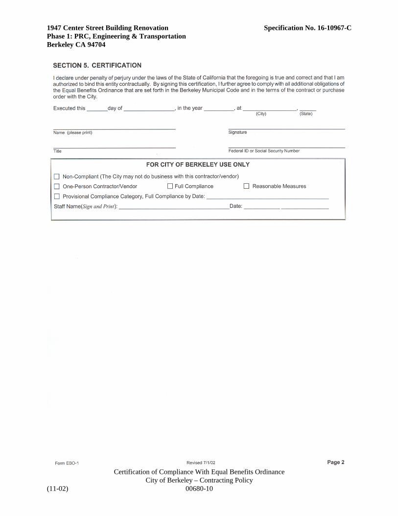
1947 Center Street Building Renovation Specification No. 16-10967-C Phase 1: PRC, Engineering & Transportation Berkeley CA 94704
Certification of Compliance With Equal Benefits Ordinance City of Berkeley – Contracting Policy
(11-02) 00680-10

1947 Center Street Building Renovation Specification No. 16-10967-C Phase 1: PRC, Engineering & Transportation Berkeley CA 94704
TAXPAYER IDENTIFICATION REPORT NAME/COMPANY'S NAME: MAILING ADDRESS: SOCIAL SECURITY NO.: OR EMPLOYER IDENTIFICATION NO.: My Company is a Corporation [ ] My Company is not a Corporation [ ] I certify that the above information is true and correct: (Signature) (Title) The Tax Equity and Fiscal Responsibility Act of 1982 (Public Law 97-248) requires the above reporting information be furnished to the City. Persons who do not furnish their tax information numbers become subject to backup withholding by the City at a rate of 20% from each disbursement made to the recipient.
END OF DOCUMENT
City of Berkeley – Contracting Policy (11-02) 00680-11

1947 Center Street Building Renovation Specification No. 16-10967-C Phase 1: PRC, Engineering & Transportation Berkeley CA 94704
CITY OF BERKELEY RIGHT TO AUDIT FORM
The Contractor agrees that pursuant to Section 61 of the Berkeley City Charter, the City Auditor's office may conduct an audit of Contractor's financial, performance and compliance records maintained in connection with the operations and services performed under this contract. In the event of such audit, Contractor agrees to provide the Auditor with reasonable access to Contractor's employees and make all such financial, performance and compliance records available to the Auditor's office. City agrees to provide Contractor an opportunity to discuss and respond to any findings before a final audit report is filed. Contractor's signature _____________________________ Date: _________________ Print Name and Title: ______________________________________________________ Company: _____________________________________________________________
City of Berkeley – Contracting Policy (11-02) 00680-12

AGREEMENT TO BE BOUND
The undersigned, as a Contractor or Subcontractor (“Contractor”) on a City Project (“Project”), for
and in consideration of the award to it of a contract to perform work on said Project, and in further
consideration of the mutual promises made in the Project’s Community Workforce Agreement
(“Agreement”), a copy of which was received and is acknowledged, hereby:
1. Accepts and agrees to be bound by the terms and conditions of the Agreement, together with
any and all amendments and supplements now existing or which are later made to said
Agreement.
2. Certifies that it has no commitments or agreements which would preclude its full and complete
compliance with the terms and conditions of said Agreement;
3. Agrees to secure from any Contractor (as defined in said Agreement) which is or becomes a
subcontractor (of any tier to it, and from any successors, a duly executed Agreement to be
bound in form identical to this document.
4. Contractor agrees that it shall be bound by all applicable trust agreements and plans for the
provision of such fringe benefits as accrue to the direct benefit of the construction persons,
including Health and Welfare, Pension, Training, Vacation, and/or other direct benefits
provided pursuant to the appropriate craft agreement contained in Schedule “A” of Agreement.
Date:
Company Name:
Name of Prime Contractor or Higher Level Subcontractor:
Name of Project:
Signature:
Print Name:
Title:
Contractor’s License #:
Motor Carrier Permit (CA) #:

1947 Center Street Building Renovation Specification No. 16-10967-C Phase 1: PRC, Engineering & Transportation Berkeley CA 94704
DOCUMENT 00681
COMMUNITY WORKFORCE AGREEMENT Contractor shall comply with the City of Berkeley’s adopted employment policies applying to City construction projects as described in Document 00812. The following documents pertain to the Community Workforce Agreement: • City Council Item from June 23, 2015 Agenda – Contract: Community Workforce Agreement with
Building Trades council, et. al. for Construction Projects at or Above $500,000.
• City Council Resolution No. 67,111-N.S.
• Community Workforce Agreement
• Agreement to Be Bound
• Bidding & Contracting Under the Community Workforce Agreement (CWA)
• Community Workforce Agreement Hiring Plan
• Cumulative CWA Workforce Utilization Report
City of Berkeley – Community Workforce Agreement (11-02) 00681-1

1947 Center Street Building Renovation Specification No. 16-10967-C Phase 1: PRC, Engineering & Transportation Berkeley CA 94704
City of Berkeley – Community Workforce Agreement (11-02) 00681-2

1947 Center Street Building Renovation Specification No. 16-10967-C Phase 1: PRC, Engineering & Transportation Berkeley CA 94704
DOCUMENT 00700
GENERAL CONDITIONS TABLE OF CONTENTS 1. General A. Documents B. Exercise of Contract Responsibilities 2. Bidding A. Bid Submissions B. Investigation Prior To Bidding C. Subcontractors 3. Contract Award and Commencement Of The Work A. Award of Contract B. Commencement of Work 4. Bonds and Insurance A. Bonds B. Insurance 5. Drawings and Specifications A. Intent B. Drawing Details C. Interpretation of Drawings and Specifications D. Checking of Drawings E. Standards to Apply Where Detailed Specifications Are Not Furnished F. Deviations from Specifications and Drawings G. Precedence of Documents H. Ownership and Use of Drawings, Specifications and Other Contract Documents 6. Construction by City or by Separate Contractors A. City's Right to Perform Construction and to Award Separate Contracts B. Mutual Responsibility C. Project Manager Authority Over Coordination 7. City and Payment A. City's Representatives B. Means and Methods of Construction C. Receipt and Processing of Applications for Payment 8. Control of the Work A. Supervision of Work by Contractor B. Observation of Work by Project Manager and Architect/Engineer C. Access to Work Site D. Existing Utilities 9. Warranty, Guarantee and Inspection of Work A. Warranty and Guarantee
General Conditions (10-01) 00700 - 1
1947 Center Street Building Renovation Specification No. 16-10967-C Phase 1: PRC, Engineering & Transportation Berkeley CA 94704 B. Inspection of Work C. Correction of Defective Work D. Acceptance and Correction of Defective Work by City E. Rights upon Inspection or Correction F. Samples and Tests of Materials and Work G. Proof of Compliance with Contract Provisions H. Acceptance 10. Contractor's Organization and Equipment A. Contractor's Legal Address B. Contractor's Office at the Work Site C. Contractor's Superintendents or Forepersons D. Proficiency in English E. Contractor's Employees F. Contractor to Supply Sufficient Workers and Materials G. Contractor to List Trades Working 11. Prosecution and Progress of the Work A. Schedules and Examination of Contract Documents B. Lines and Grades, Measurements C. Cost Data 12. Claims by Contractor A. General B. Procedure C. Claim Format D. Exclusive Remedy E. Mediation 13. Legal and Miscellaneous A. Laws and Regulations B. Permits and Taxes C. Responsibility of Contractor and Indemnification D. Notice of Concealed or Unknown Conditions E. Notice of Hazardous Waste or Materials Conditions F. Suspension of Work G. Termination of Contract for Cause H. Termination of Contract for Convenience I. Contingent Assignment of Subcontractors J. Remedies K. Patents L. Substitution for Patented and Specified Articles M. Interest of Public Officers N. Limit of Liability
O. Severability P. Press Release and Confidentiality Q. No Third Party Beneficiaries R. City Acting in its Proprietary Capacity S. Municipal Affairs
14. Modifications of Contract A. Alterations, Modifications and Force-Account Work B. Entire Agreement
General Conditions (10-01) 00700 - 2

1947 Center Street Building Renovation Specification No. 16-10967-C Phase 1: PRC, Engineering & Transportation Berkeley CA 94704 C. Effect of Waivers 15. Time Allowances A. Time Allowance for Performance Of Contract B. Change of Contract Times C. Notice of Delay D. No Damage for Contractor Caused Delay E. Liquidated Damages 16. Working Conditions and Prevailing Wages A. Use of Site/Sanitary Rules B. Protection of Work, Person and Property C. Responsibility for Safety and Health D. Emergencies E. Use of Roadways and Walkways F. Nondiscrimination
G. Prevailing Wages H. Public Convenience
General Conditions (10-01) 00700 - 3

1947 Center Street Building Renovation Specification No. 16-10967-C Phase 1: PRC, Engineering & Transportation Berkeley CA 94704 GENERAL CONDITIONS 1. GENERAL A. DOCUMENTS
The Contract Documents shall not be construed to create a contractual relationship of any kind (1) between Architect/Engineer or Construction Manager and Contractor, (2) between City or its representatives and a Subcontractor or Sub-sub-contractor or (3) between any persons or entities other than City and Contractor. Contractor is fully responsible for all acts and omissions of its Subcontractors, suppliers and other persons and organizations performing or furnishing any of the Work under a direct or indirect contract with Contractor just as Contractor is responsible for Contractor's own acts and omissions.
B. EXERCISE OF CONTRACT RESPONSIBILITIES
City, and Project Manager, as City's representative, do not, in exercising their responsibilities and authorities under the Contract Documents, assume any duties or responsibilities to any subcontractor or supplier, nor do City or Project Manager assume any duty of care to Contractor, its subcontractors, or suppliers. Architect/Engineer and/or Construction Manager, in exercising their responsibilities and authorities under the Contract Documents, do not assume any duties or responsibilities to any subcontractor or supplier, nor do they assume any duty of care to Contractor, its Subcontractors, or suppliers, except as expressly set forth in the Contract Documents. However, Architect/Engineer and/or Construction Manager shall be entitled to performance and enforcement of obligations under the Contract intended to facilitate performance of their duties.
2. BIDDING A. BID SUBMISSIONS
Contractors shall follow the instructions in Document 00100, Instructions to Bidders, and shall submit all documents, forms and information required for consideration of a bid. City will evaluate qualification information submitted by apparent low Bidder and, if incomplete or unsatisfactory to City, Bidder's bid may be rejected, in the sole discretion of City.
B. INVESTIGATION PRIOR TO BIDDING
1. Bidders must, prior to bidding, perform the work, investigations, research and analysis required by Article V of Document 00510 Agreement. Contractor under this Contract is charged with all information and knowledge that a reasonable bidder would ascertain from having performed this required work, investigation, research and analysis. Bid prices must include entire cost of all work "incidental" to completion of the Work, as that term is defined in Paragraph 5 of this Document.
2. Conditions Shown on the Contract Documents: Information as to underground conditions, as-built
conditions, or other conditions or obstructions, indicated in the Contract Documents, e.g., on Drawings or in Specifications, has been obtained with reasonable care, and has been recorded in good faith. However, City only warrants, and Contractor may only rely, on the accuracy of limited types of information.
a. As to above-ground conditions the Contractor is required to carefully examine the site of the
work and satisfy himself as to the as-built conditions. The Contractor is charged with the knowledge that would be obtained by a reasonable, independent investigation of the site. The submission of a Bid will be conclusive evidence that the Bidder has investigated and is fully aware of the conditions and difficulties to be encountered, of the character, quality and quantities of work to be performed and materials to be furnished.
General Conditions (10-01) 00700 - 4

1947 Center Street Building Renovation Specification No. 16-10967-C Phase 1: PRC, Engineering & Transportation Berkeley CA 94704
b. As to any subsurface condition shown or indicated in the Contract Documents, Contractor may rely only upon the general accuracy of actual reported depths, actual reported character of materials, actual reported soil types, actual reported water conditions, or actual obstructions shown or indicated. City is not responsible for the completeness of such information for bidding or construction; nor is City responsible in any way for any conclusions or opinions of Contractor drawn from such information.
3. Conditions Shown In Reports and Drawings Supplied for Informational Purposes: Reference is made to
Document 00220 Geotechnical Data and Existing Conditions for identification of geotechnical reports, "as built" information, and other drawings or other documents describing physical conditions in or relating to existing surface or subsurface conditions or structures at or contiguous to the Site.
These reports and drawings are not Contract Documents and, except for any "technical data" regarding subsurface conditions specifically identified in Document 00220 Geotechnical Data and Existing Conditions, and "Underground Facilities" data (as limited in Document 00220), Contractor may not in any manner rely on the information in these reports and drawings unless Contractor has made its own reasonable independent investigation of all conditions affecting the Work. Any perceived error, omission, conflict or ambiguity observed by the Contractor during his investigation shall be immediately brought to the attention of the Project Manager. Contractor shall not be entitled to additional compensation if a reasonable review and comparison of the documents listed in Document 220 and the Contract Documents would have uncovered the error, omission, conflict or ambiguity. [City reserves the right not to use Document 00220 if such information is not available.]
C. SUBCONTRACTORS
In accordance with Public Contract Code Section 4101 et seq., Contractor shall not substitute any other person or firm as a subcontractor in place of any of those listed in bid, nor shall any subcontractor assign or transfer subcontract, or permit the same to be performed by any other contractor without written approval of City. At City's request, Contractor shall provide City with a complete copy of all executed subcontracts or other final contractual agreements with subcontractors and/or suppliers.
3. CONTRACT AWARD AND COMMENCEMENT OF THE WORK A. AWARD OF CONTRACT
City will make the Award of Contract by issuing a Notice of Award. Contractor will be allowed ten (10) business days after receipt of the Notice of Award to deliver to City the Contract with signature affixed thereto, together with bonds prescribed by this Agreement. (See Paragraphs on surety bonds and certificates of insurance.) City will return to the Contractor a fully executed Contract within twenty (20) business days of its receipt from Contractor.
B. COMMENCEMENT OF WORK
The Contract Times will commence to run on the thirtieth (30th) day after the issuance of the Notice of Award, or, if a Notice to Proceed is given, on the day indicated in the Notice to Proceed. City may give a Notice to Proceed at any time within thirty (30) days after the Notice of Award. City reserves the right to set the commencement date at any time within sixty (60) days of Contract Award if a Notice to Proceed is given. See also Paragraph 15 hereof. Contractor shall start to perform the Work on the date when the Contract Times commence to run, but no work shall be done at the Site prior to the date on which the Contract Times commence to run.
General Conditions (10-01) 00700 - 5
1947 Center Street Building Renovation Specification No. 16-10967-C Phase 1: PRC, Engineering & Transportation Berkeley CA 94704 4. BONDS AND INSURANCE A. BONDS
1. At or before 5 o'clock p.m. of the tenth (10) business day following Notice of Award of Contract, Contractor must file with City the following bonds:
a. Corporate surety bond, in the form of Document 00610 Performance Bond, in a sum not less than
100 percent of amount of Contract, to guarantee faithful performance of Contract ("Performance Bond"); and
b. Corporate surety bond, in the form of Document 00620 Labor and Material Bond, in a sum not
less than 100 percent of amount of Contract, to guarantee payment of wages for services engaged and of bills contracted for materials, supplies, and equipment used in performance of Contract ("Labor and Material Bond").
2. Corporate sureties on these bonds and on bonds accompanying Bids must be legally authorized to
engage in business of furnishing surety bonds in State of California. Sureties must be satisfactory to City.
3. Amount of Contract, as used to determine amounts of bonds, shall be total amount fixed in
Contractor's Bid for performance of required Work (or corrected total if errors are found.) B. INSURANCE
1. By 5 o'clock p.m. of the tenth (10) business day following Notice of Award of Contract, Contractor shall furnish to City satisfactory proof that Contractor has taken out for the entire period covered by proposed contract the following types of insurance with an insurance carrier having an A.M. Best rating of VII or higher:
a. Comprehensive general liability insurance with limits as specified in Document 00810,
Supplemental General Conditions, each occurrence Bodily Injury and as specified in Document 00810, each occurrence Property Damage, including contractual liability, explosion, collapse and underground (XCU), broadform property damages, City's and Contractor's protective, and completed operations coverages. No subsidence exclusion will be accepted.
b. Comprehensive automobile liability insurance with limits as specified in Document 00810, each
person Bodily Injury, as specified in Document 00810, each occurrence Bodily Injury and as specified in Document 00810, each occurrence Property Damage, including coverage for owned, non-owned and hired vehicles.
c. All-risk course of construction insurance in an amount as specified in Document 00810, including
fire damage to property owned by City, contractor or third parties. Any deductible shall not exceed the amount specified in Document 00810, each loss and shall be borne by Contractor.
d. Environmental Liability Insurance, with limits as specified in Document 810 each occurrence,
including environmental impairment and remediation coverage, pollution liability, asbestos liability, lead paint removal, and hazardous material transportation coverages. Said policy shall cover claims arising out of hazardous material and hazardous waste remediation, storage, transportation and disposal. Said policy shall provide Bodily Injury and Property Damage Liability coverage with respect to environmental pollution damage resulting from the
General Conditions (10-01) 00700 - 6

1947 Center Street Building Renovation Specification No. 16-10967-C Phase 1: PRC, Engineering & Transportation Berkeley CA 94704
contractor=s asbestos or hazardous materials abatement activities at the project site and shall include Completed Operations coverage.
e. Full workers' compensation insurance for all persons whom Bidder may employ in carrying out
Work contemplated under Contract, in accordance with Act of Legislature of State of California, known as "Workers' Compensation Insurance and Safety Act", approved May 26, 1913, and All Acts amendatory or supplemental thereto. Workers' compensation policy shall include Employer Liability Insurance with limits as specified in Document 00810, each accident.
2. Insurance policies shall contain an endorsement containing the following terms:
a. City, their employees, representatives and agents, construction managers and Architect/Engineer,
shall be named as additional insureds, but only with respect to liability arising out of the activities of the named insured.
b. The policies shall apply separately to each insured against whom claim is made or suit is brought
except with respect to the limits of the company's liability.
c. Written notice of cancellation or of any limits reduction change in said policy shall be mailed to the City, the Project Manager and the Construction Manager thirty (30) days in advance of the effective date thereof, and ten (10) days written notice to the same in advance of payment of any insurance claims under such policies to any person, firm or entity
d. Contractor's insurance shall be primary insurance and no other insurance or self insured retention
carried or held by City shall be called upon to contribute to a loss covered by insurance for the named insured. Policies shall include cross-liability and severability of interest clauses or endorsements.
e. Automobile liability insurance coverage carried by Contractor , or by any sub-hauler hired by
Contractor, shall include Endorsement MCS 90, or its equivalent, with limits of not less than $1 million per accident, to cover liability for transportation of hazardous material.
3. Certificates of Insurance and Endorsements shall have clearly typed thereon City Contract number
and title of Contract.
4. At time of making application for extension of time, Contractor shall submit evidence that insurance policies will be in effect during requested additional period of time.
5. Nothing herein contained shall be construed as limiting in any way the extent to which Contractor
or any sub-contractor may be held responsible for payment of damages resulting from their operations.
6. Required minimum amounts of insurance may be increased should conditions of Work, in opinion
of City, warrant such increase, and Contractor shall increase amounts of insurance required herein when so directed by City to such higher amounts as City may direct.
7. Insurance shall be maintained by Contractor in full force and effect during entire period of
performance of Contract and shall be kept in force during warranty and guarantee periods, except:
a. All-risk course of construction insurance may be discontinued after final payment.
b. If Environmental Liability coverage is written on a AClaims Made@ basis, coverage must be maintained for a minimum of three years following Final Completion of the contract, and any
General Conditions (10-01) 00700 - 7

1947 Center Street Building Renovation Specification No. 16-10967-C Phase 1: PRC, Engineering & Transportation Berkeley CA 94704
Retroactive Date in the original policy covering this Contract, or in any successive policies required herein, shall not be later than the effective date of the construction contract. (In lieu of maintaining successive policies after Final Completion of the project, the contractor may elect to provide in the original policy an extended discovery period of not less than 36 months after Final Completion.)
8. If Contractor fails to maintain insurance, City may take out insurance to cover any damages of the
above mentioned classes for which City might be held liable on account of Contractor's failure to pay such damages, or compensation which City might be liable to under provisions of Workers' Compensation Insurance and Safety Act, by reason of employee of Contractor being injured or killed, and deduct and retain amount of premium from any sums due Contractor under Contract.
9. If injury occurs to employee of Contractor for which employee, or employee's dependents in the
event of employee's death, is entitled to compensation from City under provisions of Workers' Compensation Insurance and Safety Act as amended, or for which compensation is claimed from City, City may retain out of sums due Contractor under Contract, amount sufficient to cover such compensation, as fixed by Act as amended, until such compensation is paid, or until it is determined that no compensation is due, and if City is compelled to pay compensation, City will deduct and retain from such sums amount so paid.
5. DRAWINGS AND SPECIFICATIONS A. INTENT The Contract Documents are complementary; what is called for by one is as binding as if called for by all. It is the
intent of the Drawings and Specifications to describe a functionally complete and operable Project (and all parts thereof) to be constructed in accordance with the requirements of the Contract Documents. Any work, materials or equipment that may reasonably be inferred from the requirements of the Contract Documents or from prevailing custom or trade usage as being required to produce this intended result will be furnished and performed whether or not specifically called for. When words or phrases which have a well-known technical or construction industry or trade meaning are used to describe Work, materials or equipment, such words or phrases shall be interpreted in accordance with that meaning. The intent of the Drawings specifically includes the intent to depict construction that complies with all applicable laws, codes and standards. The Divisions and Sections of the Specifications and the identifications of any Drawings shall not control Contractor in dividing the Work among Subcontractors or suppliers or delineating the work to be performed by any specific trade.
Reasonably implied parts of the Work shall be performed as "incidental work" even though absent from the
Drawings and Specifications. "Incidental" work shall be performed by Contractor without extra cost to City. Incidental work includes any work not shown on Drawings nor described in Specifications, but which is necessary or normally or customarily required as a part of the Work shown on the Drawings or described in the Specifications, or is necessary or required to make each installation satisfactory, legally operable, functional, consistent with the intent of the Drawings and Specifications or the requirements of the Contract Documents. Incidental work shall be treated as if fully described in Specifications and shown on Drawings, and expense thereof shall be included in price bid. Incidental work includes, but is not limited to, tasks required to be performed under Division 1 of Specifications.
General Conditions (10-01) 00700 - 8

1947 Center Street Building Renovation Specification No. 16-10967-C Phase 1: PRC, Engineering & Transportation Berkeley CA 94704 B. DRAWING DETAILS A typical or representative detail on the Drawings shall constitute the standard for workmanship and material
throughout corresponding parts of Work. Where necessary, and where reasonably inferable from the Drawings, Contractor shall adapt such representative detail for application to such corresponding parts of Work. Repetitive features shown in outline on the Drawing shall be in exact accordance with corresponding features completely shown.
C. INTERPRETATION OF DRAWINGS AND SPECIFICATIONS Should any discrepancy appear or any misunderstanding arise as to the import of anything contained in the
Drawings and Specifications prepared by Architect/Engineer, the matter shall be referred to the Project Manager in writing, with a copy to Architect/Engineer. Architect/Engineer shall issue with reasonable promptness such written clarifications or interpretations of the requirements of the Drawings and Specifications as Architect/Engineer may determine necessary, which shall be consistent with the intent of and reasonably inferable from the Drawings and Specifications. Such written clarifications and interpretations will be binding upon Contractor, unless City in its discretion directs otherwise. Contractor shall not carry on work except with the knowledge of Project Manager. If Contractor believes that a written clarification or interpretation justifies an adjustment in the Contract Sum or Contract Times and the parties are unable to agree to the amount or extent thereof, if any, then Contractor shall perform the Work subject to the clarification and may make a written claim therefor as provided in Paragraph 12.
D. CHECKING OF DRAWINGS Before undertaking each part of the Work, Contractor shall carefully study and compare the Contract Documents
and check and verify pertinent figures shown thereon and all applicable field measurements. Contractor shall be responsible for any errors which might have been avoided by such comparison. Figures shown on Drawings shall be followed; do not scale measurements. The Contractor shall promptly report in writing to the Project Manager and Architect/Engineer, any conflict, error, ambiguity or discrepancy which Contractor may discover and shall obtain a written interpretation or clarification from Architect/Engineer before proceeding with any Work affected thereby.
E. STANDARDS TO APPLY WHERE DETAILED SPECIFICATIONS ARE NOT FURNISHED Wherever in Specifications, or in any orders given by Project Manager or Architect/Engineer pursuant to or
supplementing Specifications, it is provided that Contractor shall furnish materials or manufactured articles or shall do work for which no detailed specifications are set forth, the following general specifications shall apply. Materials or manufactured articles shall be of the best grade, in quality and workmanship, obtainable in the market from firms of established good reputation, or, if not ordinarily carried in stock, shall conform to the usual standards for first-class materials or articles of the kind required, with due consideration of the use to which they are to be put. Work for which no detailed specifications are set forth herein shall conform to the usual standards for first-class work of the kind required. Contractor shall specify in writing to Project Manager the materials used or work performed under this section no later than five (5) business days prior to furnishing such materials or performance of such work.
F. DEVIATIONS FROM SPECIFICATIONS AND DRAWINGS 1. No modification or deviation from the drawings and specifications will be permitted. Contractor must
perform work in strict accord with Drawings and Specifications. No order for any alteration, modification or extra which shall increase or decrease the cost of work shall be valid unless the resulting increase or decrease in price shall have been agreed upon in writing, and the order signed by Contractor and Project Manager (or other authorized officer representing City). Deviations from Drawings and from the dimensions therein given, or from the Specifications, whether or not error is believed to exist, shall be made only when approved in writing by Project Manager.
General Conditions (10-01) 00700 - 9
1947 Center Street Building Renovation Specification No. 16-10967-C Phase 1: PRC, Engineering & Transportation Berkeley CA 94704 2. Project Manager may order that locations, lines and grades for Work vary from those shown on Drawings.
Changes may be made in location, lines or grades for Work under any item of Contract. No extra payment in addition to unit price fixed in Contract for Work under respective items will be allowed on account of variations from Drawings in unit price items. In lump sum contracts, or where there are no unit price items covering work affected by variations of locations, lines or grades, all changes in Contract will be made in accordance with Paragraph 14, Modifications.
G. PRECEDENCE OF DOCUMENTS In the case of discrepancy or ambiguity in the Contract Documents, the following order of precedence shall
prevail: 1. Modifications in inverse chronological order, and in the same order as specific portions they are
modifying. 2. Signed Agreement, and terms and conditions referenced therein. 3. Supplementary or Special Conditions. 4. General Conditions. 5. Division 1 Specifications. 6. Division 2 through 16 Specifications and Drawings. 7. Written numbers over figures, unless obviously incorrect. 8. Figured dimensions over scaled dimensions. 9. Large-scale Drawings over small-scale Drawings. However, in the case of discrepancy or ambiguity solely between and among the Drawings and Specifications
referenced in item 6 immediately above, the discrepancy or ambiguity shall be resolved in favor of the interpretation that will provide City with the functionally complete and operable Project described in the Drawings and Specifications and if that does not resolve the discrepancy or ambiguity, then the Specifications govern over the Drawings.
H. OWNERSHIP AND USE OF DRAWINGS, SPECIFICATIONS AND OTHER CONTRACT DOCUMENTS The Contract Documents were prepared for use for the Work of this Contract only. No part of the Contract
Documents shall be used for any other construction or for any other purpose except with the written consent of City. Any unauthorized use of the Contract Documents is prohibited and at the sole liability of the user.
General Conditions (10-01) 00700 - 10

1947 Center Street Building Renovation Specification No. 16-10967-C Phase 1: PRC, Engineering & Transportation Berkeley CA 94704 6. CONSTRUCTION BY CITY OR BY SEPARATE CONTRACTORS A. CITY'S RIGHT TO PERFORM CONSTRUCTION AND TO AWARD SEPARATE CONTRACTS City may perform construction or operations related to the Project with its own forces, or award separate contracts
in connection with other portions of the Project or other construction or operations, on the site or areas contiguous to the site, under Conditions of the Contract similar to these (including those portions related to insurance and waiver of subrogation), or have other work performed by utility owners. When separate contracts are awarded for different portions of the Project or other construction or operations on the site, the term "Contractor" in the Contract Documents in each case shall mean the Contractor who executes each separate City/Contractor Agreement.
B. MUTUAL RESPONSIBILITY 1. Contractor shall afford all other contractors, utility owners, and City (if City is performing work with its own
forces), proper and safe access to the site, and reasonable opportunity for the installation and storage of their materials, shall ensure that the execution of its Work properly connects and coordinates with their work, and shall cooperate with them to facilitate the progress of the Work.
2. Contractor shall coordinate its work with the work of other separate contractors, City, and utility owners, including the holding monthly of coordination meetings with them. City or its designee shall have the right to participate in these coordination meetings, and shall be advised of the results of these coordination meetings at the Progress Meeting.
3. Unless otherwise provided in the Contract Documents, Contractor shall do all cutting, fitting and patching of
the Work that may be required to make its several parts come together properly and integrate with such other work. Contractor shall not endanger any work of others by cutting, excavating or otherwise altering their work and will only cut or alter their work with the written consent of Project Manager and the others whose work will be affected.
4. The duties and responsibilities of Contractor under paragraphs 6.B.1 to 6.B.3 above are for the benefit of
City and also for the benefit of such utility owners and other contractors working at the site to the extent that there are comparable provisions for the benefit of Contractor in said direct contracts between City and such utility owners and other contractors.
5. To the extent that any part of Contractor's Work is to interface with work performed or installed by other
contractors, Contractor shall inspect and measure the in-place work and promptly report to Project Manager in writing any defect in such in-place work that will impede or increase the cost of Contractor's interface unless corrected. Project Manager and/or its authorized representative will require the Contractor responsible for the defective work to make corrections so as to conform to its contract requirements, or, if the defect is the result of an error or omission in the Contract Documents, issue a change order. If Contractor fails to measure, inspect and/or report to Project Manager in writing defects that are reasonably discoverable, all costs of accomplishing the interface acceptably shall be borne by Contractor. This provision shall be included in any and all other contracts or subcontracts for Work to be performed where such a conflict could exist.
General Conditions (10-01) 00700 - 11

1947 Center Street Building Renovation Specification No. 16-10967-C Phase 1: PRC, Engineering & Transportation Berkeley CA 94704 C. PROJECT MANAGER AUTHORITY OVER COORDINATION 1. Project Manager shall have authority over coordination of the activities of multiple contractors in those cases
where City contracts with others for the performance of other work on the Project, City performs work with its own forces, or utilities perform work on the site. (The authority of Project Manager with respect to coordination of the activities of multiple prime contractors and utility owners, however, shall not in any manner relieve Contractor of its obligation to other contractors and utility owners to coordinate its work with utility owners and other contractors as specified above.) Contractor shall promptly notify Project Manager in writing when another contractor on this Project fails to coordinate its work with the Work of this Contract.
2. Contractor shall suspend any part of the Work herein specified or shall carry on the same in such manner if
directed by Project Manager when such suspension or prosecution is necessary to facilitate the work of other contractors or workers. No damages or claims by Contractor will be allowed therefor if the suspension or work change is due in whole or in part to Contractor's failure to perform its obligation herein specified to coordinate its work with utility owners and other contractors. If the suspension or work change is due in whole or in part to the failure of another contractor to coordinate its work with Contractor and other contractors and utility owners, then resulting damages or claims by Contractor will be allowed only to the extent of fault by City. City reserves the right to backcharge Contractor for any damages or claims of other contractors incurred as a result of Contractor's failure to perform its obligations to coordinate with other contractors and utility owners, and in its discretion, may interplead funds retained and Contractor releases City of further liability for such funds.
3. City may at any time and in its sole discretion, designate a person, firm or corporation other than the Project
Manager, to have authority over the coordination of the activities among the various prime contractors. 7. CITY AND PAYMENT A. CITY'S REPRESENTATIVES City's designated authorized representatives will have limited authority to act on behalf of City as set forth in the
Contract Documents. Except as otherwise provided in these General Conditions, City shall issue all communications to Contractor through Project Manager, and Contractor shall issue all communications to the City through Project Manager. All communications between Contractor and Architect/Engineer shall be confirmed in writing and copied to Project Manager.
B. MEANS AND METHODS OF CONSTRUCTION Subject to those rights specifically reserved in the Contract Documents, City and Project Manager shall not
supervise, direct, or have control over, or be responsible for, Contractor's means, methods, techniques, sequences or procedures of construction or for the safety precautions and programs incident thereto, or for any failure of Contractor to comply with laws and regulations applicable to the furnishing or performance of Work. City and Project Manager shall not be responsible for Contractor's failure to perform or furnish the Work in accordance with Contract Documents.
C. RECEIPT AND PROCESSING OF APPLICATIONS FOR PAYMENT Contractor shall prepare the necessary schedules required by Section 01025 Measurement and Payment, submit
applications for progress payments or final payments, and warrant title to all Work covered by each application for payment, as required by Section 01025 Measurement and Payment. City shall review Contractor's applications for payment and make payment thereon as required by Section 01025 Measurement and Payment.
General Conditions (10-01) 00700 - 12

1947 Center Street Building Renovation Specification No. 16-10967-C Phase 1: PRC, Engineering & Transportation Berkeley CA 94704 8. CONTROL OF THE WORK A. SUPERVISION OF WORK BY CONTRACTOR Contractor shall supervise, inspect and direct the work competently and efficiently, devoting such attention thereto
and applying such personal skills and expertise as may be required and necessary to perform the Work in accordance with the Contract Documents. Contractor shall be solely responsible for the means, methods, techniques, sequences and procedures of construction. The Contractor shall be responsible to see that the completed Work complies accurately with the Contract Documents.
Contractor shall keep on the Site at all times during Work progress a competent resident Superintendent, who shall
not be replaced without the express written consent of City. The Superintendent will be Contractor's representative at the site and shall have complete authority to act on behalf of Contractor. All communications to the Superintendent shall be as binding as if given to the Contractor.
B. OBSERVATION OF WORK BY PROJECT MANAGER AND ARCHITECT/ENGINEER 1. Work shall be performed under the general observation and administration of Project Manager. Contractor
shall immediately comply with orders and instructions given in accordance with terms of Contract by Project Manager, or by any authorized assistant, inspector or other representative of Project Manager acting within scope of duties entrusted, but nothing herein contained shall be taken to relieve Contractor of obligations or liabilities under Contract.
2. Architect/Engineer may provide administration of Contract and observation of the Work as hereinafter
described. 3. Architect/Engineer may advise and consult with Project Manager. Architect/Engineer may have authority to
act on behalf of City to extent provided in Contract Documents. 4. Architect/Engineer may visit Site at intervals appropriate to stage of construction to become familiar
generally with progress and quality of Work and to determine in general if Work is proceeding in accordance with Contract Documents. However, Architect/Engineer will not be required to make exhaustive or continuous on-site inspections to check quality or quantity of Work. On basis of on-site observations, Architect/Engineer will keep Project Manager informed of progress of Work, and will endeavor to guard City against defects and deficiencies in work of Contractor.
5. Architect/Engineer will not be responsible for and will not have control or charge of construction means,
methods, techniques, sequences or procedures, or for safety precautions and programs in connection with the work.
6. Architect/Engineer will not be responsible for or have control or charge over acts or omissions of Contractor,
subcontractors, or any of their agents or employees, or any other persons performing Work. 7. Architect/Engineer may review Contractor's submittals such as Shop Drawings, Product Data and Samples,
but only for conformance with design concept of Work and with information given in Contract Documents. 8. Architect/Engineer may conduct inspections to determine dates of Substantial Completion and Final
Completion, may receive and forward to Project Manager for review written warranties and related documents required by Contract and assembled by Contractor.
9. If City and Architect/Engineer agree, Architect/Engineer will furnish a Resident Project Representative to
assist Architect/Engineer in providing more continuous observation of the Work. The responsibilities and authority and limitations thereof of any Resident Project Representative and assistant will be provided in the Supplementary General Conditions or in written communication to Contractor.
General Conditions (10-01) 00700 - 13

1947 Center Street Building Renovation Specification No. 16-10967-C Phase 1: PRC, Engineering & Transportation Berkeley CA 94704 10. Architect/Engineer may issue such written clarifications or interpretations of the requirements of the Contract
Documents (in the form of Drawings and Specifications or otherwise) as Architect/Engineer may determine necessary, which shall be consistent with the intent of and reasonably inferable from the Contract Documents. Such written clarifications and interpretations will be binding on the Contractor, unless City in its discretion directs otherwise. If Contractor believes that a written clarification or interpretation justifies an adjustment in the Contract Sum or the Contract Times, Contractor must notify Project Manager, in writing, before proceeding with the work. If the parties are unable to agree to the amount or extent thereof, if any, then Contractor shall perform the Work as so clarified or interpreted and may make a written claim therefor as provided in Paragraph 12.
11. Based on the observations of Architect/Engineer, Architect/Engineer may make recommendations to Project
Manager to disapprove or reject Work which Architect/Engineer believes to be defective, or that Architect/Engineer believes will not produce a complete Project that conforms to the Contract Documents or that will prejudice the integrity of the design concept of the completed Project as a functioning whole as indicated by the Contract Documents. Architect/Engineer will also have authority to require special inspection or testing of Work, whether or not the work is fabricated, installed or completed.
C. ACCESS TO WORK SITE During performance of Work, City and its agents, consultants, and employees may at any time enter upon Work,
shops where any part of Work may be in preparation, or factories where any materials for use in Work are being or are to be manufactured, and Contractor shall provide proper and safe facilities therefor, and shall make arrangements with manufacturers to facilitate inspection of their processes and products to such extent as City's interests may require. Other contractors performing work for City may also, for all purposes required by their respective contracts, enter upon Work. Subject to this right, Contractor shall have sole care, custody and control of its work areas.
D. EXISTING UTILITIES 1. Pursuant to Government Code Section 4215, City shall be responsible, as between City and Contractor, for
the timely removal, relocation or protection of existing main or trunk line utility facilities located on the project site, if, and only if, such utilities are not identified in the drawings and specifications made a part of the invitation for bids. City shall compensate Contractor for the cost of locating and repairing damage not due to the failure of Contractor to exercise reasonable care, and removing and relocating such utility facilities not indicated on the drawings and specifications with reasonable accuracy, and for equipment on the project necessarily idled during such work, such compensation to be determined in accordance with the provisions of these General Conditions.
2. Nothing herein shall be deemed to require City to indicate the presence of existing service laterals or
appurtenances whenever the presence of such utilities on the site can be inferred from the presence of other visible facilities, such as buildings, meters and junction boxes, on or adjacent to the site of the construction. If Contractor, while performing Contract, discovers utility facilities not identified by City in the contract drawings or specifications, it shall immediately notify City and the utility in writing.
General Conditions (10-01) 00700 - 14

1947 Center Street Building Renovation Specification No. 16-10967-C Phase 1: PRC, Engineering & Transportation Berkeley CA 94704 9. WARRANTY, GUARANTEE AND INSPECTION OF WORK A. WARRANTY AND GUARANTEE 1. Contractor represents and warrants that it is and will be at all times fully qualified and capable of performing
every phase of the Work to complete the Work in accordance with the terms of the Contract Documents. Contractor warrants that all construction work and construction services shall be performed in accordance with generally accepted professional standards of good and sound construction practices and all requirements of the Contract Documents. Subject to the last sentence of this paragraph, Contractor warrants that the Work, including but not limited to each item of materials and equipment incorporated therein, shall be new, shall be of suitable grade of its respective kind for its intended use, shall be free from defects in design, engineering, materials, construction and workmanship, and shall conform in all respects with all applicable requirements of federal, state and local laws, licenses, and permits, the Drawings and Specifications and all descriptions set forth therein, applicable construction codes and standards, and all other requirements of the Contract Documents. Notwithstanding the foregoing, Contractor shall not be responsible for the negligence of others in the specification of specific equipment, materials, design parameters, means or methods of construction, where that is specifically shown and expressly required by the Contract Documents.
2. Extended Guarantees: If any guaranty exceeding one year is provided by the supplier or manufacturer of any
equipment used in this Project, then the guarantee for such materials shall be extended for such term. Contractor expressly agrees to act as co-guarantor of such equipment and materials, and contractor shall supply Owner with all warranty and guarantee documents relative to equipment and materials incorporated in the job and guaranteed by their suppliers or manufacturers.
3. Environmental and Toxics Warranty: The covenants, warranties and representations contained in this section
9.A.3 will be effective on the date of recording of the Notice of Completion or, if no such Notice is filed, then on the date of Final Completion and will, survive completion of the project. Contractor covenants, warrants and represents to Owner that:
a. No litigation is pending or, to Contractor's knowledge, proposed, threatened or anticipated with respect
to the Contractor, or with respect to any other matter affecting the Project or the operation thereof. b. To Contractor's knowledge after due inquiry, no lead or asbestos-containing materials were installed or
were discovered in the Project at any time during Contractor's construction thereof. If any such materials were discovered, Contractor made immediate written disclosure to City.
c. To Contractor's knowledge after due inquiry, no electrical transformers, light fixtures with ballasts or
other equipment containing PCB's are or were located on the Project at any time during Contractor's construction thereof.
d. To Contractor's knowledge after due inquiry, no storage tanks for gasoline or any other toxic substance
are or were located on the Project at any time during Contractor's construction thereof. e. Contractor's operations concerning the Project are and were not in violation of any applicable
environmental federal, state, or local statute, law or regulation dealing with hazardous materials substances or toxic substances, and no notice from any governmental body has been served upon Contractor claiming any violation of any such law, ordinance, code or regulation, or requiring or calling attention to the need for, any work, repairs, construction, alteration, or installation on or in connection with the Project in order to comply with any such laws, ordinances, codes or regulations, with which Contractor has not complied. If there are any such notices with which Contractor has complied, Contractor shall provide City with copies thereof.
General Conditions (10-01) 00700 - 15

1947 Center Street Building Renovation Specification No. 16-10967-C Phase 1: PRC, Engineering & Transportation Berkeley CA 94704 B. INSPECTION OF WORK 1. All materials, equipment and workmanship used in the Work shall be subject to inspection or testing at all
times during construction and/or manufacture in accordance with the terms of this Contract. Work and materials, and manufacture and preparation of materials, from beginning of construction until Final Completion and acceptance of Work, shall be subject to inspection and rejection by Project Manager, its agents, or independent contractors retained by Project Manager to perform inspection services, or governmental agencies with jurisdictional interests. Contractor shall provide them proper and safe conditions for such access and advise them of Contractor's site safety procedures and program so that they may comply therewith as applicable.
2. Contractor shall give Project Manager timely notice of readiness of the Work for all required inspections,
tests or approvals, and shall cooperate with inspection and testing personnel to facilitate required inspections or tests.
3. If applicable laws or regulations of any public body having jurisdiction require any Work (or part thereof)
specifically to be inspected, tested or approved by an employee or other representative of such public body, Contractor shall assume full responsibility for arranging and obtaining such inspections, tests or approvals, and furnish Project Manager with the required certificates of inspection, or approval. City shall pay the cost of initial testing and Contractor shall pay all costs in connection with any follow up or additional testing. Contractor shall also be responsible for arranging and obtaining and shall pay all costs in connection with any inspections, tests or approvals required for Project Manager's and/or Architect/Engineer's acceptance of materials or equipment to be incorporated in the Work, or of materials, mixed designs, or equipment submitted for approval prior to Contractor's purchase thereof for incorporation in the Work.
4. If any Work (or the work of others) that is required to be inspected, tested or approved is covered by
Contractor prior to such inspection, testing or approval, without written approval of Project Manager, it must, if requested by Project Manager, be uncovered. Uncovering Work shall be at Contractor's expense unless Contractor has given Project Manager timely notice of Contractor's intention to cover the same and Project Manager has given its written approval of the covering of the Work.
5. In any case where Work is covered contrary to the written request of Project Manager, it must, if requested
by Project Manager, be uncovered for Project Manager's observation or inspection at Contractor's expense. 6. Whenever required by Project Manager, Contractor shall furnish tools, labor and materials necessary to make
examination of Work that may be completed or in progress, even to extent of uncovering or taking down portions of finished Work. Should Work be found unsatisfactory, cost of making examination and of reconstruction shall be borne by Contractor. If Work is found to be satisfactory, examination will be paid for by City in manner herein prescribed for paying for alterations, modifications and extra work, except as otherwise herein specified.
C. CORRECTION OF DEFECTIVE WORK 1. If the Work is defective, or Contractor fails to supply sufficient skilled workers or suitable materials or
equipment, or fails to furnish or perform the Work in such a way that the completed Work will conform to the Contract Documents, the Project Manager may order Contractor to replace the defective work or to stop the Work, or any portion thereof, until the cause for such order has been eliminated; however, this right of Project Manager to stop the Work shall not give rise to any duty on the part of Project Manager to exercise this right for the benefit of Contractor or any other party.
2. If required by Project Manager, Contractor shall promptly, as directed by Project Manager, without cost to
City and in accordance with Project Manager's written instructions, (i) correct such defective Work, whether or not fabricated, installed or completed, or, if it has been rejected by Project Manager, remove it from the
General Conditions (10-01) 00700 - 16

1947 Center Street Building Renovation Specification No. 16-10967-C Phase 1: PRC, Engineering & Transportation Berkeley CA 94704
Site and replace it with Work that is not defective, and (ii) satisfactorily correct or remove and replace any damage to other Work or the work of others resulting therefrom. All claims, costs, losses, and damages caused by or resulting from such correction or removal (including but not limited to all costs of repair or replacement of work of others) as well as all costs of City incurred in exercising such rights and remedies (including, but not limited to, the costs incurred in the examination, evaluation and determination that such defective Work should be corrected or removed and replaced) will be the responsibility of Contractor and a change order will be issued incorporating the necessary revisions in the Contract Documents with respect to Work and the Contract Sum. If the parties are unable to agree on the amount of an appropriate decrease in the Contract Sum, City may deduct from monies due Contractor all claims, costs, losses, and damages caused by or resulting from such correction or removal (including but not limited to all costs of repair or replacement of work of others) as well as all costs of City incurred in exercising such rights and remedies (including, but not limited to, the costs incurred in the examination, evaluation and determination that such defective Work should be corrected or removed and replaced). If Contractor disagrees with City's calculation, it may make a claim as provided in Paragraph 12. City's rights under this paragraph shall be in addition to any other rights it may have under the Contract Documents, including, without means of limitation, in Paragraph 9.C.3 and 9.D.
3. Correction Period: If within one year after the date of Final Completion or such longer period of time as may
be prescribed by laws or regulations or by the terms of any applicable special guarantee required by the Contract Documents or by any specific provision of the Contract Documents, any Work is found to be defective, Contractor shall promptly, without cost to City and in accordance with City or Project Manager's written instructions, (i) correct such defective Work or, if it has been rejected by City or Project Manager, remove it from the site and replace it with Work that is not defective, and (ii) satisfactorily correct or remove and replace any damage to other Work or the work of others resulting therefrom. If Contractor does not promptly comply with the terms of such instructions, or in an emergency where delay would cause serious risk of loss or damage, City may have the defective Work corrected or the rejected Work removed and replaced, and all claims, costs, losses and damages caused by or resulting from such removal and replacement (including but not limited to all costs of repair or replacement of work of others) shall be paid by Contractor.
4. In special circumstances where a part of the Work is occupied or a particular item of equipment is placed in
continuous service before Final Completion of all the Work, the correction period for that part of the Work or that item may start to run from an earlier date if so provided by Contract Modification.
5. Where defective or rejected Work (and damage to other work resulting therefrom) has been corrected,
removed or replaced under this provision after the commencement of the correction period, the correction period hereunder with respect to such Work will be extended for an additional period of one year after such correction or removal and replacement has been satisfactorily completed.
D. ACCEPTANCE AND CORRECTION OF DEFECTIVE WORK BY CITY 1. City may accept defective Work: If, instead of requiring correction or removal and replacement of defective
Work, City (and, prior to final payment, also Project Manager) prefers to accept it, City may do so. Contractor shall pay all claims, costs, losses and damages attributable to City's evaluation of and determination to accept such defective Work. If any such acceptance occurs prior to final payment, a change order will be issued incorporating the necessary revisions in the Contract Documents with respect to Work, unless the parties are unable to agree upon an appropriate decrease in the Contract Sum, in which case City may deduct from monies due Contractor the amount of any and all claims, costs, losses (including diminution in value), damages, expenses and liabilities attributable to the defective work. If Contractor disagrees with the deduction, the Contractor may make a claim as provided in Paragraph 12. If the acceptance occurs after Final Payment, an appropriate amount shall be paid by Contractor as determined by City.
2. City may correct untimely or defective Work: If Contractor fails within five (5) days after written notice
General Conditions (10-01) 00700 - 17

1947 Center Street Building Renovation Specification No. 16-10967-C Phase 1: PRC, Engineering & Transportation Berkeley CA 94704
from City or Project Manager to correct defective Work or to remove and replace rejected Work as required by Project Manager in accordance with paragraph 9.C.2, or provide a plan for correction of defective Work acceptable to City, or if Contractor otherwise fails to perform the Work in accordance with Contract Documents (including material delays from approved schedules), City may (at its sole option), after seven (7) days written notice to Contractor, correct and remedy any deficiency. In connection with such corrective and remedial action, City may exclude Contractor from all or part of the site, take possession of all or part of the Work, and suspend Contractor's work related thereto, take possession of all or part of Contractor's tools, appliances, construction equipment and machinery at the site, and incorporate in the Work any materials and equipment stored at the site or for which City has paid Contractor but which are stored elsewhere. Contractor shall allow City, its representatives, agents, employees, and other contractors and Architect/Engineer's consultants access to the site to enable City to exercise the rights and remedies under this paragraph. All claims, costs, losses (including diminution in value), damages, expenses and liabilities incurred or sustained by City in exercising such rights and remedies will be the responsibility of Contractor and a change order will be issued incorporating the necessary revisions in the Contract Documents with respect to Work and the Contract Sum. If the parties are unable to agree on the amount of an appropriate decrease in the Contract Sum, City may deduct from monies due Contractor all claims, costs, losses (including diminution in value), expenses, damages and liabilities attributable to the defective Work, including all costs of repair or replacement of work of others destroyed or damaged by correction, removal or replacement of Contractor's defective Work. (If Contractor disagrees with City's calculation, it may make a claim as provided in Paragraph 12.)
E. RIGHTS UPON INSPECTION OR CORRECTION 1. The Contractor shall not be allowed an extension of the Contract Times (or any milestones) because of any
delay in the performance of Work attributable to the exercise by City of its rights and remedies under this Paragraph. Where City exercises its rights under this paragraph, it retains all other rights it has by law or under the Contract Documents, including but not limited to, the right to terminate the Contract and/or make a claim or backcharge where a change order cannot be agreed upon.
2. Inspection shall not relieve the Contractor of its obligation to have furnished material and workmanship in
accordance with Contract Documents. Payment for work completed through periodic progress payments or otherwise shall not operate to waive the City's right to require full compliance with the Contract Documents and shall in no way be deemed as acceptance of the Work paid therefor. Contractor's obligation to complete the Work in accordance with the Contract Documents shall be absolute, unless City agrees otherwise in writing.
F. SAMPLES AND TESTS OF MATERIALS AND WORK 1. Samples or test specimens of all materials to be used or offered for use in connection with this work shall be
prepared at expense of Contractor and furnished to Project Manager and Architect/Engineer in such quantities and sizes as may be required for proper examination and tests.
2. All samples shall be submitted in ample time to enable Project Manager and Architect/Engineer to make any
tests, analyses or examinations necessary before the time at which it is desired to incorporate the material into the work.
3. Project Manager and Architect/Engineer may refuse consideration of further samples of same brand or make
of material or product previously determined as unsatisfactory for testing, analysis or examination. 4. Test samples or specimens of material for testing shall be taken by Architect/Engineer, his or her
representative, Project Inspector or representative of the testing agency. G. PROOF OF COMPLIANCE WITH CONTRACT PROVISIONS
General Conditions (10-01) 00700 - 18

1947 Center Street Building Renovation Specification No. 16-10967-C Phase 1: PRC, Engineering & Transportation Berkeley CA 94704 In order that City or Project Manager may determine whether Contractor has complied or is complying with
requirements of Contract not readily enforceable through inspection and tests of Work and materials, Contractor shall at any time when requested submit to City or Project Manager properly authenticated documents or other satisfactory proofs of compliance with requirements.
H. ACCEPTANCE Neither inspection by City or its authorized agents or representatives, nor any order or certificate for the payment
of money, nor any payment, nor acceptance of the whole or any part of the Work by City, nor any extension of time, nor any position taken by City or its authorized agents or representatives shall operate as a waiver of any provisions of this Contract, or of any power herein reserved City or any right to damage herein provided, nor shall any waiver of any breach of this Contract be held to be a waiver of any other subsequent breach.
10. CONTRACTOR'S ORGANIZATION AND EQUIPMENT A. CONTRACTOR'S LEGAL ADDRESS Address and telecopy number given in bid is hereby designated as legal address and telecopy number of
Contractor, but such address and/or number may be changed at any time by notice in writing, delivered to City, which in conspicuous language advises City of a change in legal address or telecopy number. Delivery to Contractor's legal address or depositing in any post office or post office box regularly maintained by United States Postal Service, in a postpaid wrapper, directed to Contractor at legal address, of any drawing, notice, letter or other communication, shall be deemed legal and sufficient service thereof upon Contractor. Telecopy to Contractor's designated telecopy number of any letter, memorandum, or other communication on standard or legal sized paper, with proof of telecopy transmission, shall be deemed legal and sufficient service thereof upon Contractor.
B. CONTRACTOR'S OFFICE AT THE WORK SITE Contractor is required to maintain an office at Site, which office shall be headquarters of representative authorized
to transmit and receive instructions, drawings or other communications to and from Project Manager. Instructions, drawings, or other communications given to Contractor's representative or delivered at work-site office in representative's absence shall be deemed to have been given to Contractor.
C. CONTRACTOR'S SUPERINTENDENT Contractor shall at all times be represented on Site by one or more superintendents authorized and competent to
receive and carry out any instructions that may be given to them by Project Manager and Contractor shall be liable for faithful observance of instructions delivered to Contractor or to authorized representative or representatives on Site.
D. PROFICIENCY IN ENGLISH Supervisors, security guards, safety personnel and employees who have unescorted access to the Site must possess
proficiency in the English language in order to understand, receive and carry out oral and written communications or instructions relating to their job functions, including safety and security requirements.
General Conditions (10-01) 00700 - 19

1947 Center Street Building Renovation Specification No. 16-10967-C Phase 1: PRC, Engineering & Transportation Berkeley CA 94704 E. CONTRACTOR'S EMPLOYEES Contractor shall employ only competent and skillful personnel to do work. If Project Manager shall notify
Contractor that any person on Work is incompetent, unfaithful or disorderly, or fails to observe customary standards of conduct or refuses to carry out provisions of Contract, or uses threatening or abusive language to any person on Work representing City, or violates sanitary rules, or is otherwise unsatisfactory, and if Project Manager requests that such person be discharged from the work, then such person shall be immediately discharged from Work and shall not be employed again on it except with consent of Project Manager.
F. CONTRACTOR TO SUPPLY SUFFICIENT WORKERS AND MATERIALS 1. Unless otherwise required by City pursuant to the terms of the Contract Documents, Contractor shall at all
times keep on the premises a sufficient amount of materials and employ a sufficient number of qualified workers to prosecute Work at a rate and in a sequence and manner necessary to complete Work herein required within the Contract Times. This obligation shall remain in full force and effect notwithstanding disputes or claims of any type.
2. Should Contractor at any time during progress of Work refuse, neglect, or be unable to supply sufficient
materials or qualified workers to prosecute Work as required, then upon receipt of notice to that effect from Project Manager, City or its designee may notify Contractor, at no cost to City, to accelerate the Work and/or furnish additional qualified workers or materials as Project Manager may consider necessary, and if Contractor does not comply with notice from Project Manager, City or City's designee within 3 business days of date of service thereof, City shall have right but not a duty to provide materials and qualified workers to finish the Work or any affected portion of the Work, as City may elect. Sums necessary to meet expenses thereby incurred shall be deducted from monies due or which may thereafter become due under Contract, and paid to persons supplying materials and doing work. Amount of such payments shall be deducted from fund or appropriation set aside for purposes of Contract and charged to Contractor as if paid to Contractor. Contractor shall remain liable for resulting delay, including liquidated damages and indemnification of City from claims of others.
3. Exercise by City or Project Manager of the rights conferred upon them in paragraph 2, immediately above, is
entirely discretionary on the part of City and Project Manager. Neither City nor Project Manager shall have any duty or obligation to exercise the rights referred to in paragraph 2 above, and the failure to exercise such rights shall not be deemed an approval of existing work progress or a waiver or limitation of City's or Project Manager's right to exercise such rights in other concurrent or future similar circumstances. The rights conferred upon City under paragraph 2 above are cumulative to City's other rights under the Contract Documents.
4. All machinery and equipment owned or controlled by Contractor which is proposed to be employed by
him on the work shall be of a type and of sufficient size, quantity and condition to produce a satisfactory quality of work within the time provided for the completion of the work.
G. CONTRACTOR TO LIST TRADES WORKING To assist inspectors and Project Manager, Contractor shall list on a daily basis what trades are working on the Site
and their scheduled activities.
General Conditions (10-01) 00700 - 20

1947 Center Street Building Renovation Specification No. 16-10967-C Phase 1: PRC, Engineering & Transportation Berkeley CA 94704 11. PROSECUTION AND PROGRESS OF THE WORK A. SCHEDULES AND EXAMINATION OF CONTRACT DOCUMENTS 1. Before undertaking each part of Work, Contractor shall carefully study and compare the Contract Documents
and check and verify pertinent figures shown thereon and all applicable field measurements and all actual conditions. Contractor shall promptly report in writing to Project Manager and Architect/Engineer any conflict, error, ambiguity or discrepancy which Contractor may discover and shall obtain a written interpretation or clarification from Architect/Engineer before proceeding with any Work affected thereby.
2. Contractor shall submit to Project Manager and Architect/Engineer for review: a. Progress schedules and reports shall be submitted as required by Specification Sections 01300 and
01310. Contractor shall utilize the Progress Schedule in planning, scheduling, coordinating, per-forming and controlling the work (including all activities of Subcontractors, assigned contractors, equipment vendors and suppliers). Contractor shall update Progress Schedule on a monthly basis for purpose of recording and monitoring the progress of Work and evaluating and preparing Contractor's monthly progress payments.
b. Within ten (10) business days after the Notice of Award, Contractor shall submit a preliminary
schedule of Shop Drawing and Sample submittals which will list each required submittal and the times for submitting, reviewing and processing such submittal, as required by Specification Section 01300. If no such schedule is agreed upon, then all Shop Drawings, Samples and product data submittals shall be completed and submitted within thirty (30) business days after receipt of Notice to Proceed from City.
c. Within ten (10) business days after the Notice of Award, Contractor shall submit a preliminary
schedule of values for all the Work which will include quantities and prices of items aggregating the Contract Sum and will subdivide each schedule of value into component activities in sufficient detail to serve as the basis for progress payments during construction. Such Schedule of Values will include an appropriate amount of overhead and profit applicable to each item of work, will include a line item for project record documents, and a line item for project scheduling, and will conform to Specification Section 01025, Measurement and Payment.
3. Unless otherwise provided in the Contract Documents, at least fifteen (15) days before submission of the
First Application for Payment, a conference attended by Contractor, Architect/ Engineer, Project Manager, and others as appropriate, will be held to review for acceptability the schedules submitted in accordance with the above subparagraph 2. The Contractor shall have an additional fifteen (15) days to make corrections and adjustments and to complete and resubmit the schedules. Schedules shall be updated and completed as required by Specification Sections 01025, 01300 and 01310. No progress payment shall be due or owing to Contractor until the schedules are submitted to and acceptable to Project Manager as meeting the requirements of the Contract Documents (including Specification Sections 01025, 01300 and 01310.) Project Manager's acceptance of Contractor's schedules will not create any duty of care or impose on City or Project Manager any responsibility for the sequencing, scheduling or progress of Work nor will it interfere with or relieve Contractor from Contractor's full responsibility therefor.
4. Before commencing any portion of Work, Contractor shall inform Project Manager in writing as to time and
place at which Contractor wishes to commence Work, and nature of work to be done, in order that proper provision for inspection of Work may occur, and to assure measurements necessary for record and payment. Information shall be given to Project Manager a reasonable time in advance of time at which Contractor proposes to begin Work, so that Project Manager may make necessary preliminary work without inconvenience or delay to Contractor.
5. Contractor shall submit submittals and shop drawings to Architect/Engineer for review in strict accordance
General Conditions (10-01) 00700 - 21

1947 Center Street Building Renovation Specification No. 16-10967-C Phase 1: PRC, Engineering & Transportation Berkeley CA 94704
with Section 01300 Submittals. Submission of a Shop Drawing shall constitute Contractor's representation that all requirements of Section 01300 Submittals have been complied with. All submittals will be identified as Architect/Engineer may require and in the number of copies specified in Section 01300 Submittals.
6. Contractor shall not perform work requiring submission of a Shop Drawing or Sample or other submittal
prior to submission and favorable review of the Shop Drawing or Sample or submittal. Where a Shop Drawing or Sample or other submittal is required by the Contract Documents or the final schedule of Shop Drawing and Sample submissions accepted by Project Manager and Architect/Engineer, any related Work performed prior to Architect/Engineer's approval of the pertinent submittal will be at the sole expense, responsibility and risk of Contractor.
B. LINES AND GRADES, MEASUREMENTS 1. Work shall be done to lines and grades established by Contractor at Contractor's cost in accordance with
Contract Documents, unless Project Manager, in its sole discretion, directs otherwise. 2. At request of Project Manager, Contractor shall, without charge, provide workers from Contractor's force,
and tools and materials, to assist Project Manager temporarily in making measurements and surveys and in establishing temporary or permanent reference marks. At times it may be necessary to discontinue portions of Contractor's work in order for Project Manager to make measurements or surveys without interruptions or other interference that might impair accuracy of results. At any time, on request of Project Manager, Contractor shall discontinue work to such extent as may be necessary for purposes of Project Manager.
3. No direct payment will be made for cost to Contractor of any work or delay occasioned by establishing or
checking lines and grades or making other measurements, or by inspection, and no extension of time will be allowed for such delays.
C. COST DATA 1. Contractor shall maintain full and correct information as to number of workers employed in connection with
each subdivision of Work, classification and rate of pay of each worker in form of certified payrolls, cost to Contractor of each class of materials, tools and appliances used by Contractor in Work, and amount of each class of materials used in each subdivision of Work. Contractor shall provide Project Manager with written monthly summaries of this information. If Contractor maintains summaries or reports comparing actual project costs with bid estimates or budgets, it shall provide Project Manager with a copy of such report whenever it is generated.
2. Contractor shall submit to City daily job reports recording all significant activity on the job, including the
number of workers on site, work activities, problems encountered and delays. Contractor shall take monthly progress photographs of all areas of the Work. Contractor shall maintain copies of all correspondence with sub-contractors and records of meetings with subcontractors. Contractor shall report to the surety promptly upon receiving requests from the surety to provide reporting. Contractor shall provide daily job reports as required by City and/or specified in Section 01310.
3. City shall have the right to audit Contractor's books and records and to inspect the site, including Contractor's
trailer, or other job site office, and this requirement shall be contained in the subcontracts of subcontractors working on site. City shall have the right to inspect and obtain copies of the following documents at all times: all contract documents, all planning and design documents, all Bid proposal and negotiation documents, all design modification proposals, all value engineering or other cost reduction proposals, all revisions made to the original design, and to all job progress reports, daily reports, correspondence and photographs.
4. Contractor shall maintain in a safe place at the site one record copy of all Drawings, Specifications, Addenda,
General Conditions (10-01) 00700 - 22

1947 Center Street Building Renovation Specification No. 16-10967-C Phase 1: PRC, Engineering & Transportation Berkeley CA 94704
Contract Modifications, Change Orders, Work Directives, Force Account orders, and written interpretations and clarifications in good order and annotated to show all changes made during construction. These record documents together with all approved Samples and a counterpart of all approved Shop Drawings shall be maintained and be available to Project Manager for reference. Prior to Final Completion of the Work, these Record Documents, Samples and Shop Drawings shall be delivered to Project Manager.
5. City and City Auditor, and his or her designee, shall have the right to inspect all information and documents
maintained under this provision at any time during the Project and for a period of five years following Substantial Completion. This right of inspection shall be specifically enforceable in a court of law, either independently, or in conjunction with enforcement of any other rights in the Contract Documents. City's right of inspection shall not relieve contractor of its duties and obligations under this contract.
12. CLAIMS BY CONTRACTOR A. GENERAL 1. Contract Interpretation Disputes: Should it appear to Contractor that the Work to be performed or any of the
matters relative to the Contract Documents are not satisfactorily detailed or explained therein, or should any questions arise as to the meaning or intent of the Contract Documents, the Contractor shall give written notice to City through Project Manager. Contractor shall bear all costs incurred in the giving of such notice. All issues regarding the interpretation of the Drawings or Specifications shall be referred to Architect/Engineer for interpretation. City shall have the right, but not the obligation, to affirm or disaffirm Architect/Engineer interpretation, which affirmance or disaffirmance shall be final. All issues regarding the General Conditions, General Specifications or non-engineering or non-technical aspects of the Work shall be determined by City whose determination shall be final. If the Contractor should disagree with City's decision, the Contractor's sole and exclusive remedy is to file a claim in accordance with this Paragraph. Notwithstanding and pending the resolution of any claim, the Contractor shall diligently prosecute the disputed Work to Final Completion.
2. Work Disputes: Should any dispute arise under this Contract respecting the true value of any Work
performed, of any Work omitted, of any extra Work which the Contractor may be required to perform, time extensions, respecting the size of any payment to the Contractor during the performance of this Contract, or of compliance with Contract procedures, said dispute shall be decided by City and its decision shall be final and conclusive. If the Contractor should disagree with City's decision, the Contractor's sole and exclusive remedy is to file a claim in accordance with this Paragraph. Notwithstanding and pending the resolution of any claim, the Contractor shall diligently prosecute the disputed Work to Final Completion.
3. "Claim" means a written demand or written assertion by Contractor seeking, as a matter of right, the payment
of money, the adjustment or interpretation of Contract terms, or other relief arising under or relating to the Contract Documents. In order to qualify as a "claim," the written demand must state that it is a claim submitted under Paragraph 12 of Document 00700 General Conditions.
4. A voucher, invoice, payment application, or other routine or authorized form of request for payment is not a
claim under the Contract. If such request is disputed as to liability or amount, then the disputed portion of the submission may be converted to a claim under the Contract by submitting a separate claim in compliance with claim submission requirements.
5. The provisions of this paragraph survive termination or Final Completion of this Contract. Contractor shall
bear all costs incurred in the preparation and submission of a claim.
General Conditions (10-01) 00700 - 23

1947 Center Street Building Renovation Specification No. 16-10967-C Phase 1: PRC, Engineering & Transportation Berkeley CA 94704 B. PROCEDURE 1. Should any clarification, determination, action or inaction by City or Architect/Engineer, work, or any other
event, in the opinion of Contractor, exceed the requirements of or not comply with the Contract Documents, or otherwise result in Contractor seeking additional compensation for any reason (collectively "disputed Work"), then Contractor and City shall make good faith attempts to resolve any and all such issues, claims and/or disputes. Before commencing the disputed Work, or within seven (7) calendar days after such demand is made or instruction is given, whichever is earlier, Contractor must file a written notice of the disputed work with Project Manager stating clearly and in detail its objection and reasons for contending the Work or interpretation is outside the requirements of the Contract Documents. If a written notice of disputed work is not issued within this time period, or if Contractor proceeds with the disputed Work without first having given the notice required by this paragraph, Contractor shall waive its rights to further claim on the specific issue.
2. City will review Contractor's timely notice of disputed Work and provide a decision. If, after receiving the
decision, Contractor disagrees with it or still considers the Work required of it to be outside of the requirements of the Contract, it shall so notify Project Manager, in writing, within seven (7) calendar days after receiving the decision, that a formal claim will be issued. Within thirty (30) calendar days of receiving the decision, Contractor shall submit its claim in the form specified herein and all arguments, justification, cost or estimates, schedule analysis, and detailed documentation supporting its position. Contractor's failure to furnish notification within seven (7) calendar days and all justifying documentation within thirty (30) calendar days will result in Contractor waiving its right to the subject claim. If disputed Work persists longer than thirty (30) days, then Contractor shall, every thirty (30) days until the disputed Work ceases, submit to City a document titled "Claim Update" which shall update and quantify all elements of the Claim. Contractor's failure to submit a Claim Update or to quantify costs every thirty (30) days shall result in waiver of the claim for that thirty (30) day period. Claims or claim updates stating that damages will be determined at a later date shall not comply with this paragraph and shall result in Contractor waiving its claim(s).
3. Upon receipt of Contractor's formal claim including all arguments, justifications, cost or estimates, schedule
analysis, and documentation supporting its position as previously stipulated, City or its designee will review the issue and render a final determination. If Contractor's claims at Final Completion total less than $375,000, then claims resolution shall proceed in the manner prescribed by Article 1.5, Chapter 1, Part 3 of Division 2 of the California Public Contract Code.
4. Claims shall be calculated in the same manner as Change Orders. EXCEPT WHERE PROVIDED BY
LAW, OR ELSEWHERE IN THESE CONTRACT DOCUMENTS (IF APPLICABLE), CITY SHALL NOT BE LIABLE FOR SPECIAL OR CONSEQUENTIAL DAMAGES, AND CLAIMS SHALL NOT INCLUDE SPECIAL OR CONSEQUENTIAL DAMAGES.
C. CLAIM FORMAT Contractor shall submit the claim justification in the following format: (a) Cover letter and certification, (b)
summary of claim including underlying facts, entitlement, quantum calculations, contract provisions supporting relief, (c) list of documents relating to claim including specifications, drawings, clarifications/requests for information, schedules, other, (d) chronology of events and correspondence, (e) analysis of claim merit, (f) analysis of claim cost, (g) attach supporting documents referenced in (c).
General Conditions (10-01) 00700 - 24

1947 Center Street Building Renovation Specification No. 16-10967-C Phase 1: PRC, Engineering & Transportation Berkeley CA 94704 D. EXCLUSIVE REMEDY Contractor's performance of its duties and obligations specified in this Paragraph 12 and submission of a claim as
provided in this Paragraph 12 is Contractor's sole and exclusive remedy for the payment of money, extension of time, the adjustment or interpretation of Contract terms or other contractual or tort relief arising from this Contract. This exclusive remedy and the limitation of liability (expressed herein and elsewhere throughout this Agreement) apply notwithstanding the completion, termination, suspension, cancellation, breach or rescission of the Work or this Agreement, negligence or strict liability by City, its representatives, consultants or agents, or the transfer of the Work or the Project to City for any reason whatsoever. Contractor waives all claims of waiver, estoppel, release, bar, or any other type of excuse for non-compliance with the claim submission requirements. Compliance with the notice and claim submission procedures described in this Paragraph 12 is a condition precedent to the right to commence litigation, file a Government Code Claim, or commence any other legal action. No claim or issues not raised in a timely protest and timely claim submitted under this Paragraph may be asserted in any Government Code Claim, subsequent litigation, or legal action.
E. MEDIATION All Claims not subject to the claim resolution procedures set forth in Section 01060 (Regulatory requirements),
paragraph 1.05, shall, as a condition precedent to litigation thereon, first be mediated. Mediation shall be non-binding and utilize the services of a mediator mutually acceptable to the parties, and, if the parties cannot agree, then shall utilize the services of a mediator selected by the American Arbitration Association from its panel of approved mediators trained in construction industry mediation. All statutes of limitation shall be tolled from the date of the demand for mediation until a date two weeks following the mediation's conclusion. All pending claims shall be submitted to the same mediator. The cost of the mediation shall be paid in equal parts by City and Contractor.
13. LEGAL AND MISCELLANEOUS A. LAWS AND REGULATIONS Contractor shall keep fully informed of and shall comply with all laws, ordinances, regulations and orders of any
properly constituted authority affecting Contract, Work to be done, and persons connected with Work, and shall protect and indemnify City and its officers, employees, consultants and agents against any claim or liability, including attorney's fees, arising from or based on violation of law, ordinance, regulation or order, whether by Contractor or by subcontractors, employees or agents. Authorized persons may at any time enter upon any part of Work to ascertain whether laws, ordinances, rules or orders are being complied with.
Whenever the Drawings and Specifications require large sizes or higher standards than are required by the
regulations, the Drawings and Specifications shall govern. Whenever the Drawings and Specifications require something which will violate such laws, ordinances, regulations or orders, then such laws, ordinances, regulations or orders shall govern.
B. PERMITS AND TAXES Contractor shall procure all permits and licenses, pay all charges and fees, including fees for street opening and
closing permits, and give all notices necessary and incident to due and lawful prosecution of Work, unless otherwise provided herein. City will pay applicable building permits, school, sanitation, and permanent water connection fees except as otherwise provided in the Contract Documents. Contractor shall pay all sales taxes levied on materials, supplies, or equipment purchased and used on or incorporated into Work, and all other taxes properly assessed against equipment or other property used in connection with Work. Contractor shall make necessary arrangements with proper authorities having jurisdiction over roads, streets, pipelines, navigable waterways, railroads and other works in advance of operations, even though permits for Work may have already been obtained by City.
General Conditions (10-01) 00700 - 25

1947 Center Street Building Renovation Specification No. 16-10967-C Phase 1: PRC, Engineering & Transportation Berkeley CA 94704 C. RESPONSIBILITY OF CONTRACTOR AND INDEMNIFICATION 1. City and all of its officers and employees associated with Work, including, but not limited to, Project
Manager, and each representative of City, including its officers, consultants, agents, and employees, respectively, shall not be liable or accountable in any manner for:
a. loss or damage that may happen to Work or any part thereof; b. loss or damage to materials or other things used or employed in performing Work; c. injury, sickness, disease, or death of any person, including, but not limited to, workers and the public;
or d. damage to property; resulting from any cause whatsoever except their sole negligence or active negligence, attributable to
performance or character of Work, and Contractor releases said parties from any and all such claims. 2. To the furthest extent permitted by California Civil Code Section 2782, Contractor shall assume defense of,
and indemnify, and hold harmless City and all of its officers and employees connected with Work, Project Manager and all other representatives of City, and their officers, consultants, agents, and employees, from claims, suits, actions, losses and liability of every kind, nature and description, including but not limited to attorney's fees and consultant's fees, directly or indirectly arising out of, connected with or resulting from performance of Work, failure to perform Work, or condition of Work which is caused in whole or part by any act or omission of Contractor, subcontractors, any one directly or indirectly employed by any of them or any one for whose acts any of them may be liable, regardless of whether it is caused in part by the negligence of City or any party required to be indemnified hereunder.
3. With respect to third party claims against Contractor, Contractor waives any and all rights to any type of
express or implied indemnity against City and all of its officers and employees connected with Work, including Project Manager and each representative of City, and their officers, consultants, agents, and employees.
4. Approval or Purchase of any insurance contracts or policies shall in no way relieve from liability nor limit the
liability of Contractor, its subcontractors of any tier, or the officers or agents of any of them. 5. To the furthest extent permitted by Civil Code Section 2782, the indemnities, releases of liability and
limitations of liability, and limitations of remedy expressed throughout this Contract shall apply even in the event of breach of Contract, negligence (active or passive), fault or strict liability of the party indemnified, released, or limited in liability, and shall survive the termination, rescission, breach, or completion of this Contract. If Contractor fails to perform any of these defense or indemnity obligations, City may in its discretion backcharge Contractor for its costs and damages resulting therefrom and withhold such sums from progress payments or other contract monies which may become due.
D. NOTICE OF CONCEALED OR UNKNOWN CONDITIONS 1. Before commencing work of digging trenches or excavation, Contractor shall review all information
available regarding subsurface conditions, including but not limited to, information supplied in Document 00220 Geotechnical Data and Existing Conditions, and subject to the terms and conditions of these documents, Contractor shall also contact Underground Service Alert ("USA") and secure from it all information in its possession regarding underground conditions, including Underground Facilities at the Site. Contractor is charged with knowledge of all subsurface conditions reflected in USA records. Prior to
General Conditions (10-01) 00700 - 26

1947 Center Street Building Renovation Specification No. 16-10967-C Phase 1: PRC, Engineering & Transportation Berkeley CA 94704
commencing excavation or trenching work, Contractor shall provide City with copies of all USA records secured by Contractor. Contractor shall advise City of any conflict between information provided in Document 00220 Geotechnical Data and Existing Conditions and that provided by USA records.
2. If either of the following conditions is encountered at Site, notice by Contractor shall be given in writing to
Project Manager promptly before conditions are disturbed (except in an emergency as required by paragraph 16.D), and in no event later than seven (7) days after first observance of:
a. Subsurface or latent physical conditions which differ materially from those indicated in the Contract
Documents. b. Unknown physical conditions of an unusual nature, different materially from those ordinarily
encountered and generally recognized as inherent in work of the character provided for in Contract Documents.
3. In response to Contractor's written notice, Project Manager will investigate the identified conditions, and if
they differ materially and cause increase or decrease in Contractor's cost of, or time required for, performance of any part of Work, Project Manager will issue a change order under the procedures described in the Contract Documents.
4. If Project Manager determines that physical conditions at Site are not latent or are not materially different
from those indicated in the Contract Documents or that no change in terms of Contract is justified, Project Manager shall so notify Contractor in writing, stating reasons. If City and Contractor do not agree on an adjustment in Contract Sum or Contract Times, Contractor shall proceed with Work as directed by Project Manager and may file a claim as provided for in Paragraph 12.
5. Contractor shall not be entitled to any adjustment in the Contract Sum or Times regarding claimed latent or
materially different site conditions if: a. Contractor knew of the existence of such conditions at the time Contractor submitted its bid; or b. Contractor should have known of the existence of such condition as a result of having fully complied
with the requirements of Paragraph 2 herein; or c. The information or conditions claimed by Contractor to be latent or materially different consist of
information, conclusions, opinions or deductions of the kind that Paragraph 2 herein precludes reliance upon; or
d. If Contractor failed to give the written notice within the time required above. 6. If City and Contractor are unable to agree on entitlement to or as to the amount or length of any adjustment in
the Contract Sum or Contract Times required under this paragraph, Contractor may make a claim as provided in Paragraph 12.
7. The cost of all of the following will be included in the Contract Sum and Contractor shall have full
responsibility for: a. Reviewing and checking all available information and data, including but not limited to, Document
00220 Geotechnical Data and Existing Conditions, and information on file at USA; b. Locating all Underground Facilities shown or indicated in Contract Documents, available information,
or indicated by visual observation, including but not limited to, and by way of example only, engaging qualified locating services and all necessary backhoeing and potholing.
General Conditions (10-01) 00700 - 27

1947 Center Street Building Renovation Specification No. 16-10967-C Phase 1: PRC, Engineering & Transportation Berkeley CA 94704 c. Coordination of Work with the owners of such Underground Facilities during construction, and d. The safety and protection of all such Underground Facilities and repairing any damage thereto resulting
from Work. 8. If an Underground Facility is uncovered or revealed at or contiguous to the site which was not shown or
indicated in the materials supplied by City or in information on file at USA, Contractor shall, promptly after becoming aware thereof and before further disturbing conditions affected thereby (and in no event later than seven (7) days), and prior to performing any Work in connection therewith (except in an emergency as required by paragraph 16.D), identify the owner of such Underground Facility and give written notice to that owner and to Project Manager. During such time, Contractor shall be responsible for the safety and protection of such Underground Facility as provided in paragraph 11.D.
9. Contractor shall be allowed an increase in the Contract Sum or an extension of the Contract Times, or both,
to the extent that they are attributable to the existence of any Underground Facility that is owned and was built by City only where the Underground Facility:
a. Was not shown or indicated in the Contract Documents or in the information supplied pursuant to
Document 00220 Geotechnical Data and Existing Conditions, or in information on file at USA; and b. The Contractor did not know of it; and c. The Contractor could not reasonably have been expected to be aware of it or to have anticipated it from
the information available. (For example, if surface conditions such as pavement repairs, valve covers, or other markings, indicate the presence of an Underground Facility, then a Change Order will not be due, even if the Underground Facility was not indicated in the Contract Documents or in the information supplied to the Contractor pursuant to Document 00220 Geotechnical Data and Existing Conditions, or in information on file at USA.)
10. Contractor shall bear the risk that Underground Facilities not owned or built by City may differ in nature or
locations shown in information made available by City pursuant to Document 00220 Geotechnical Data and Existing Conditions, or in information on file at USA. Underground Facilities are inherent in construction involving digging of trenches or other excavations and Contractor is to apply its skill and industry to verify the information available.
11. Paragraphs 13.D.2 through 13.D.4 shall only apply to contracts involving digging of trenches or excavations
of greater than four (4) feet in depth, and, for purposes of Public Contract Code Section 7104, specifically identified "technical data" shall be treated as information "indicated" by the Contract Documents.
E. NOTICE OF HAZARDOUS WASTE OR MATERIALS CONDITIONS 1. Notice by Contractor shall be given in writing to Project Manager promptly, before any of the following
conditions are disturbed (except in an emergency as required by Paragraph 16.D), and in no event later than 24 hours after first observance, of any:
a. material that Contractor believes may be material that is hazardous waste or hazardous material, as
defined in Section 25117 of the Health and Safety Code, that is required to be removed to a Class I, Class II, or Class III disposal site in accordance with provisions of existing law;
b. other material which may present a substantial danger to persons or property exposed thereto in
connection with Work at the site.
General Conditions (10-01) 00700 - 28

1947 Center Street Building Renovation Specification No. 16-10967-C Phase 1: PRC, Engineering & Transportation Berkeley CA 94704 Except as otherwise provided in the Contract Documents or as provided by applicable law, no notice shall be
required to be given by the Contractor for the disturbance or observation of any such hazardous waste or hazardous material where such material is disturbed or observed as part of the scope of Work under the Contract (such as hazardous waste or hazardous material investigation, remediation or disposal activities which are identified as the subject of Work under the Contract), where Contractor complies with all requirements in Contract Documents respecting such materials.
2. Contractor's written notice shall indicate whether the hazardous waste or material was shown or indicated in
the Contract Documents to be within the scope of Work, and whether the materials were brought to the site by Contractor, its Subcontractors, suppliers, or anyone else for whom Contractor is responsible. As used in this section the term "hazardous materials" shall include asbestos, lead, PCBs, petroleum and related hydrocarbons, and radioactive material.
3. In response to Contractor's written notice, Project Manager shall promptly investigate the identified
conditions, and if finding that conditions do involve hazardous waste or hazardous materials which cause decrease or increase in Contractor's cost of, or time required for, performance of any part of Work, Project Manager will issue a change order under the procedures required by the Contract Documents.
4. If Project Manager determines that conditions do not involve hazardous materials or that no change in terms
of Contract is justified, Project Manager shall so notify Contractor in writing, stating reasons. If City and Contractor cannot agree on an adjustment in Contract Sum or Contract Times, Contractor shall proceed with Work as directed by Project Manager and may file a claim as provided under Paragraph 12.
5. Contractor shall not be entitled to any adjustment in the Contract Sum or Times regarding claimed hazardous
waste or hazardous materials if: a. Contractor knew of the existence of such hazardous material or hazardous waste at the time Contractor
submitted its bid, including information supplied in Document 00220 Hazardous Material Surveys or information obtained by Consultant as a result of Consultant's additional or supplementary examinations, investigations, explorations, tests, studies and data concerning the conditions at or contiguous to the Site prior to submitting its bid; or
b. Contractor should have known of the existence of such hazardous material or hazardous waste as a
result of its having the responsibility to obtain additional or supplementary examinations, investigation, explorations, tests, studies and data concerning the conditions at or contiguous to the Site prior to submitting its bid; or
c. If Contractor failed to give the written notice within the time required above. 6. If after receipt of notice from Project Manager, Contractor does not agree to resume work based on a
reasonable belief it is unsafe, or does not agree to resume work under special conditions, then City may order such portion of Work that is in connection with such hazardous condition or such affected area to be deleted from the Work, or performed by others, or City may invoke its rights to terminate the Contract in whole or in part. City will determine entitlement to or the amount or extent of an adjustment, if any, in Contract Sum or Contract Times as a result of deleting such portion of Work, or performing the Work by others. If Contractor does not agree with City's determination, it may make a claim therefore as provided in Paragraph 12.
7. If Contractor stops Work in connection with any hazardous condition and in any area affected thereby,
Contractor shall immediately redeploy its workmen, equipment and materials, as necessary, to other portions of the Work to minimize delay and disruption.
General Conditions (10-01) 00700 - 29

1947 Center Street Building Renovation Specification No. 16-10967-C Phase 1: PRC, Engineering & Transportation Berkeley CA 94704 F. SUSPENSION OF WORK City may, without cause, order Contractor in writing to suspend, delay or interrupt Work in whole or in part for
such period of time as City may determine. An adjustment shall be made for increases in cost of performance of Contract caused by any such suspension, delay or interruption. No adjustment shall be made to extent: (a) that performance is, was or would have been so suspended, delayed or interrupted by another cause for which Contractor is responsible; or (b) that an equitable adjustment is made or denied under another provision of Contract; or (c) that the suspension of work was the direct or indirect result of Contractor's failure to perform any of its obligations hereunder. Adjustments made in cost of performance may have a mutually agreed fixed or percentage fee.
G. TERMINATION OF CONTRACT FOR CAUSE 1. Contractor shall be in default of this Contract and City may terminate Contractor's right to proceed under the
Contract Documents, for cause: a. Should Contractor make an assignment for the benefit of creditors, admit in writing its inability to pay
its debts as they become due, file a voluntary petition in bankruptcy, be adjudged a bankrupt or insolvent, file a petition or answer seeking for itself any reorganization, arrangement, composition, readjustment, liquidation, dissolution, or similar relief under any present or future statute, law, or regulation, filing any answer admitting or not contesting the material allegations of a petition filed against Contractor in any such proceeding, or seek, consent to, or acquiesce in, the appointment of any trustee, receiver, custodian or liquidator of Contractor or of all or any substantial part of the properties of Contractor, or if Contractor, its directors or shareholders, take action to dissolve or liquidate Contractor; or
b. Should Contractor commit a material breach of this Agreement and not cure such failure within ten (10)
calendar days of the date of notice from City to Contractor demanding such cure; or, if such failure is curable but not curable within such ten (10) day period, within such period of time as is reasonably necessary to accomplish such cure. (In order for Contractor to avail itself of a time period in excess of 10 calendar days, Contractor must provide City within the 10 day period with a written plan acceptable to City to cure said breach, and then diligently commence and continue such cure according to the written plan); or
c. Should Contractor violate or allow a violation of any valid law, statute, regulation, rule, ordinance,
permit, license or order of any governmental agency applicable to the Project or Work and does not cure such violation within ten (10) days of the date of the notice from City to Contractor demanding such cure; or, if such failure is curable but not curable within such ten (10) day period, within such period of time as is reasonably necessary to accomplish such cure. (In order for Contractor to avail itself of a time period in excess of 10 calendar days, Contractor must provide City within the 10 day period with a written plan to cure said violation acceptable to City, and then diligently commence and continue performance of such cure according to the written plan.)
2. If City at any time reasonably believes that Contractor is or may be in default under its Contract, as defined
above, City may in its sole discretion notify Contractor of this fact and request written assurances from Contractor of performance of the Contract and a written plan from Contractor to remedy any failures to perform the terms of the Contract which City may advise the Contractor of in writing. Failure of the Contractor to provide written assurances of performance as required herein will constitute a material breach of this Contract sufficient to invoke paragraph 13.G.1.b above.
3. In event of termination for cause, City shall immediately serve written notice thereof upon Surety and
Contractor. Surety shall have the rights and obligations set forth in the Performance Bond. Subject to the Surety's rights under the Performance Bond (which rights are waived upon a default under the Performance
General Conditions (10-01) 00700 - 30

1947 Center Street Building Renovation Specification No. 16-10967-C Phase 1: PRC, Engineering & Transportation Berkeley CA 94704
Bond), City may take over Work and prosecute it to completion by contract or by any other methods it may deem advisable.
4. In the event of termination by City as provided in subparagraph (1) above for cause, a. City shall compensate Contractor for the value of the Work delivered to City upon termination as
determined in accordance with the Contract Documents, subject to all rights of offset and backcharges, and provided that Contractor provides City with updated as built and project record documents showing the work performed up to the date of termination. However, City shall not compensate Contractor for its costs in terminating the Work or any cancellation charges owed to third parties;
b. Contractor shall deliver to City possession of the Work in its then condition, including but not limited
to, all designs, engineering, project records, cost data of all types, Drawings and Specifications and contracts with vendors and subcontractors, and all other documentation associated with the Project, and all construction supplies and aids dedicated solely to performing Work which, in the normal course of construction, would be consumed or only have salvage value at the end of the construction period. The Contractor shall remain fully liable for the failure of any Work completed and materials and equipment provided through the date of such termination to comply with the provisions of the Contract Documents. The provisions of this Paragraph shall not be interpreted to diminish any right which City may have to claim and recover damages for any breach of this Agreement, but rather, Contractor shall compensate City for all loss, cost, damage, expense, and/or liability suffered by City as a result of such termination and failure to comply with the Contract Documents.
5. In the event a termination for cause is determined to have been made wrongfully or without cause, then the
termination shall be treated as a termination for convenience, and Contractor shall have no greater rights than it would have had if a termination for convenience had been effected. Any Contractor claim arising out of a termination for default shall be made in accord with the provisions of the Contract Documents on claims and calculated in accordance with the provisions of the Contract Documents on Change Orders and claims. No other loss, cost, damage, expense or liability may be claimed, requested or recovered by Contractor.
H. TERMINATION OF CONTRACT FOR CONVENIENCE 1. City may terminate performance of Work under Contract in accordance with this clause in whole, or from
time to time in part, whenever City shall determine that termination is in best interest of City. Termination shall be effected by delivery to Contractor of notice of termination specifying extent to which performance of Work under Contract is terminated, and date upon which termination becomes effective.
2. After receipt of notice of termination, and except as otherwise directed by City, Contractor shall: a. Stop Work under Contract on date and to extent specified in notice of termination; b. Place no further orders or subcontracts for materials, services, or facilities except as necessary to
complete portion of Work under Contract which is not terminated; c. Terminate all orders and subcontracts to extent that they relate to performance of Work terminated by
notice of termination; d. Assign to City in manner, at times, and to extent directed by City, all right, title, and interest of
Contractor under orders and subcontracts so terminated. City shall have right, in its discretion, to settle or pay any or all claims arising out of termination of orders and subcontracts;
e. Settle all outstanding liabilities and all claims arising out of such termination of orders and
subcontracts, with approval or ratification of City to extent City may require. City's approval or
General Conditions (10-01) 00700 - 31

1947 Center Street Building Renovation Specification No. 16-10967-C Phase 1: PRC, Engineering & Transportation Berkeley CA 94704
ratification shall be final for purposes of this clause; f. Transfer title to City, and deliver in manner, at times, and to extent, if any, directed by City, fabricated
or unfabricated parts, Work in process, completed Work, supplies, and other material produced as part of, or acquired in connection with performance of, Work terminated by notice of termination, and completed or partially completed drawings, drawings,information, and other property which, if Contract had been completed, would have been required to be furnished to City;
g. Use best efforts to sell, in manner, at times, to extent, and at price or prices that City directs or
authorizes, any property of types referred to in Paragraph 13.H.2.f. above, but Contractor shall not be required to extend credit to any purchaser, and may acquire any such property under conditions prescribed and at price or prices approved by City. Proceeds of transfer or disposition shall be applied in reduction of payments to be made by City to Contractor under Contract or shall otherwise be credited to price or cost of Work covered by Contract or paid in such other manner as City may direct;
h. Complete performance of part of Work as shall not have been terminated by notice of termination; and i. Take such action as may be necessary, or as City may direct, for protection and preservation of
property related to Contract which is in possession of Contractor and in which City has or may acquire interest.
3. After receipt of notice of termination, Contractor shall submit to City termination claim, in form and with
certification City prescribes. Claim shall be submitted promptly but in no event later than 6 months from effective date of termination. Contractor and City may agree upon whole or part of amount or amounts to be paid to Contractor because of total or partial termination of Work under this clause. If Contractor and City fail to agree, on whole amount to be paid to Contractor because of termination of Work under this clause, City shall determine, on basis of information available to it, amount, if any, due to Contractor by reason of termination and shall pay to Contractor for Work specified in Contract which is performed before effective date of notice of termination, total (without duplication of any items) of -
a. Reasonable cost to Contractor, without profit, for all Work performed prior to notice of termination,
including Work done to secure project for termination. In determining reasonable cost, deductions will be made for cost of materials to be retained by Contractor, amounts realized by sale of materials, and for other appropriate credits against cost of Work. Reasonable cost will include reasonable allowance for project overhead and general administrative overhead not to exceed a total of 10 percent of direct costs of such work.
b. When, in opinion of City, cost of contract item of work is excessively high due to costs incurred to
remedy or replace defective or rejected work, reasonable cost to be allowed will be estimated reasonable cost of performing work in compliance with requirements of Drawings and Specifications and excessive actual cost shall be disallowed.
c. Reasonable allowance for profit on cost of Work performed as determined under Paragraph 13.H.1,
provided Contractor establishes to satisfaction of City that Contractor would have made a profit had Contract been completed and provided further, that profit allowed shall not exceed 5 percent of cost.
d. Reasonable cost to Contractor of handling material returned to vendor, delivered to City or otherwise
disposed of as directed by City. e. Reasonable allowance for Contractor's administrative costs in preparing termination claim. f. City shall have no obligation to pay Contractor under this paragraph 13.H unless and until Contractor
provides City with updated and acceptable as-builts and project record documents for work completed
General Conditions (10-01) 00700 - 32

1947 Center Street Building Renovation Specification No. 16-10967-C Phase 1: PRC, Engineering & Transportation Berkeley CA 94704
prior to termination. In no event shall City be liable for costs incurred by Contractor or subcontractors after receipt of a notice of
termination. Such non-recoverable costs include, but are not limited to, anticipated profits on Contract, post-termination employee salaries, post-termination administrative expenses, post-termination overhead or unabsorbed overhead, costs of preparing and submitting bid, attorney's fees or other costs relating to prosecution of claim or lawsuit.
4. In arriving at amount due Contractor under this clause there shall be deducted: a. all unliquidated advance or other payments on account theretofore made to Contractor, applicable to
terminated portion of Contract, b. any claim which City may have against Contractor in connection with Contract, and c. the agreed price for, or proceeds of sale of, any materials, supplies, or other things kept by Contractor
or sold, under provisions of this clause, and not otherwise recovered by or credited to City. I. CONTINGENT ASSIGNMENT OF SUBCONTRACTORS Each subcontract agreement for a portion of the Work is assigned by Contractor to City provided that: 1. Assignment is effective only after termination of Contract by City for cause pursuant to Paragraph 13.G
above or for convenience pursuant to Paragraph 13.H above; and, 2. Assignment is effective only for those subcontract agreements which City accepts by notifying the
Subcontractor in writing; and 3. Assignment is subject to the prior rights, if any, of the surety, obligated by the bond provided under the
Contract, where the Surety exercises its rights to complete the Contract. J. REMEDIES Subject to the Contract provisions regarding Contractor claims, claim review, and claim resolution, and subject to
the limitations therein, all claims, counter-claims, disputes and other matters in question between City and Contractor arising out of or relating to this agreement or its breach will be decided in a court of competent jurisdiction within the State of California, County of Alameda. All City remedies provided in this Contract shall be taken and construed as cumulative; that is, in addition to each and every other remedy herein provided; and City shall have any and all equitable and legal remedies which it would have according to law.
K. PATENTS Fees or claims for any patented invention, article or arrangement that may be used upon or in any manner
connected with performance of Work or any part thereof, shall be included in price bid for doing Work. Contractor shall save, keep, bear harmless, and fully indemnify City, and any of its officers, employees, agents, or consultants from all damages, claims for damages, costs or expenses in law or equity, including attorney's fees, that may at any time arise or be set up for any infringement of the patent rights, copyright, trade name, trademark, service mark, trade secret or other like intellectual property of any person or persons in consequence of use by City, or any of its officers, agents, or consultants of articles to be supplied under the contract and of which Contractor is not patentee or assignee or has not lawful right to sell the same. Such costs or expenses for which Contractor agrees to indemnify and hold harmless the above indemnities includes but is not limited to any and all license fees, whether such fees are agreed to indemnitee or ordered by a court or administrative body of competent jurisdiction.
General Conditions (10-01) 00700 - 33

1947 Center Street Building Renovation Specification No. 16-10967-C Phase 1: PRC, Engineering & Transportation Berkeley CA 94704 L. SUBSTITUTION FOR PATENTED AND SPECIFIED ARTICLES Except as noted specifically in Specifications, whenever in Specifications, material or process is designated by
patent or proprietary name or by name of manufacturer, such designation shall be deemed to be used for purpose of facilitating description of material and process desired, and shall be deemed to be followed by the words "or equivalent", and Contractor may offer any substitute material or process which Contractor considers equal in every respect to that so designated, and if material, or process, offered by Contractor is, in opinion of Project Manager, equal in every respect to that so designated, its use will be approved. Contractor shall submit to Project Manager a separate request for substitution pursuant to Section 1630 Substitutions of the Specifications.
M. INTEREST OF PUBLIC OFFICERS No representative, officer, or employee of City, no member of the governing body of the locality in which the
Project is situated, and no other public official of such locality or localities who exercises any functions or responsibilities with respect to the Project, during the tenure of the official or for one year thereafter, shall have any interest, direct or indirect, in this contract or the proceeds thereof.
N. LIMIT OF LIABILITY CITY, ITS EMPLOYEES, OFFICERS, DIRECTORS, CONSULTANTS OR AGENTS SHALL HAVE NO
LIABILITY TO CONTRACTOR FOR SPECIAL, CONSEQUENTIAL OR INCIDENTAL DAMAGES, EXCEPT TO THE LIMITED EXTENT THAT THESE CONTRACT DOCUMENTS OR APPLICABLE PUBLIC CONTRACTING STATUTES MAY SPECIFY THEIR RECOVERY.
O. SEVERABILITY Any provisions or portions thereof of this Agreement prohibited by, unlawful, or unenforceable under any
applicable law of any jurisdiction shall as to such jurisdiction be ineffective without affecting other provisions or portions thereof in this Agreement. If the provisions of such applicable law may be waived, they are hereby waived to the end that this Agreement may be deemed to be a valid and binding agreement enforceable in accordance with its terms. If any provisions or portion thereof of this Agreement are prohibited by, unlawful, or unenforceable under any applicable law and are therefore stricken or deemed waived, the remainder of the provisions and this Agreement shall be interpreted to achieve the goals or intent of the stricken or waived provisions or portions thereof to the extent such interpretation is consistent with applicable law.
P. PRESS RELEASE AND CONFIDENTIALITY
1. Contractor agrees that no press releases, articles for professional journals, speeches, confidential information, or other kinds of publicity concerning the project shall be released, made, or generated by Contractor or its employees or agents without the prior written consent of the City.
2. The term "Confidential Information" means all unpublished information obtained or received from the
during the term of this Contract which relates to the City's business affairs. Contractor shall not disclose confidential information to any person, except to its employees and subcontractors to the extent that they require it in the performance of their work, during the term of this Contract and until authorized by the in writing. Contractor and its subcontractors shall hold all confidential information in trust and confidence for the City, and shall use confidential information only for the purpose of this Contract. Contractor and its subcontractors shall require all of their employees to whom confidential information is revealed to comply with these provisions. Contractor shall have an agreement with each Subcontractor and supplier requiring their compliance with the foregoing.
General Conditions (10-01) 00700 - 34

1947 Center Street Building Renovation Specification No. 16-10967-C Phase 1: PRC, Engineering & Transportation Berkeley CA 94704 Q. NO THIRD PARTY BENEFICIARIES This Agreement is entered into solely for the benefit of the City. Nothing herein is intended to benefit, directly
or indirectly, any third party, including, but not limited to, employees, sub-contractors, or bidders. R. CITY ACTING IN ITS PROPRIETARY CAPACITY
Contractor acknowledges and agrees that City is entering this Contract solely in its proprietary capacity, completely separate and distinct from any regulatory capacity. Therefore, delays or additional costs, if any, resulting from their exercise and performance of police powers by any Department of the City shall in no way constitute a delay or justification for claims for which the City, as contractee, is responsible.
S. MUNICIPAL AFFAIRS
The Work described in this Contract constitutes a municipal affair of the City of Berkeley, a charter city existing pursuant to Article 11, Section 5 of the California Constitution. Except as expressly required by the City Charter, applicable ordinances, or this Contract, the terms of the California Public Contract Code shall be deemed inapplicable hereto.
14. MODIFICATIONS OF CONTRACT A. ALTERATIONS, MODIFICATIONS AND FORCE-ACCOUNT WORK
1. No modification or deviation from the Contract Documents will be permitted except by written addenda,
written change order or written Supplemental Instruction. 2. Project Manager, before the date of Final Completion of Work, may order changes in Work or Contract
Times herein required, and may order extra materials and extra work in connection with performance of Contract, and Contractor shall promptly comply with such orders. Any such orders shall be diligently carried out by Contractor in accordance with the Contract Documents. If changes ordered in design, workmanship or materials are of such a nature as to increase or decrease cost of any part of Work, price fixed in Contract shall be increased or decreased by amount as Contractor and City may agree upon as reasonable and proper allowance for increase or decrease in cost of Work. If agreement cannot be reached, then City shall reach a determination, which shall be final, subject to Contractor's rights under Paragraph 12 herein.
3. Alterations, modifications or extras which result in change in Contract Sum or Contract Times or both, shall
be effected by written Contract Modification which has been approved by City or Project Manager. Those alterations or modifications which do not result in change in Contract Sum or Contract Times, and do not substantially change Drawings or Specifications, shall be effected only by written directive to Contractor from Project Manager.
4. Contractor shall, upon request by City, permit inspection of the original unaltered Contract bid estimate,
subcontract agreements, and purchase orders relating to the change; and documents substantiating all costs associated with the cost proposal.
5. Changes in the Work made pursuant to this Paragraph and extensions of Contract time necessary by reason
thereof shall not in any way release the guarantees/warranties given by Contractor pursuant to provisions of the Contract Documents, nor shall such changes in the Work relieve or release the sureties of bonds executed pursuant to said provisions. The sureties, in executing such bonds, shall be deemed to have expressly agreed to any such change in the Work and to any extension of time made by reason thereof.
6. Procedures for Modifications of Contract are given in Section 01035 Modification Procedures of the
Specifications.
General Conditions (10-01) 00700 - 35

1947 Center Street Building Renovation Specification No. 16-10967-C Phase 1: PRC, Engineering & Transportation Berkeley CA 94704 B. ENTIRE AGREEMENT The Contract Documents, and any Contract Modifications, shall represent the entire and integrated agreement
between City and Contractor regarding the subject matter of this agreement and shall constitute the exclusive statement of the terms of the parties' agreement. The Contract Documents, and any Contract Modifications, shall supersede any and all prior negotiations, representations or agreements, either written or oral, express or implied, that relate in any way to the subject matter of this agreement or written modifications. City and Contractor represent and agree that they are entering into this agreement and any subsequent written modification in sole reliance upon the information set forth in the Contract Documents or Contract Modifications and the parties are not and will not rely on any other information.
C. EFFECT OF WAIVERS Either party's waiver of any breach or failure to enforce any of the terms, covenants, conditions or other provisions
of the Contract Documents at any time shall not in any way affect, limit, modify or waive that party's right thereafter to enforce or compel strict compliance with every term, covenant, condition or other provision hereof, any course of dealing or custom of the trade or oral representations notwithstanding.
15. TIME ALLOWANCES A. TIME ALLOWANCE FOR PERFORMANCE OF CONTRACT 1. When Contract has been signed by Contractor and City, City will serve a Notice to Proceed upon Contractor
to that effect, either by depositing notice in a post office or post office box regularly maintained by United States Postal Service in a postpaid wrapper directed to Contractor at legal address, or (at City's option) by delivery by other means at legal address.
2. Start date for Contract Times shall be on the date indicated in the Notice to Proceed. If no date is indicated,
then the start date for Contract Times shall be the fifth (5th) calendar day from date that Contractor receives, by hand delivery or by facsimile transmission, Project Manager's written Notice to Proceed, unless the Notice to Proceed is served by mail only, then the Start Date under the Contract shall be the tenth (10th) calendar day following the date of mailing. Total number of calendar days for Substantial and Final Completion of Work on Contract shall be as provided in Document 00510.
B. CHANGE OF CONTRACT TIMES 1. The Contract Times (or milestones) may only be changed by Change Order or Written Amendment and all
time limits stated in the Contract Documents are of the essence of the Agreement. The Contract Times (or milestones) will be adjusted in an amount equal to the time lost due to the following:
a. Changes in the Work ordered by City; b. Acts or neglect by City, or its Project Manager, acts or neglect of utility owners, acts or neglect of other
Contractors performing other Work, provided Contractor has fully and completely performed its responsibilities under the Contract Documents, including but not limited to, its cooperation and coordination responsibilities required by the Contract Documents;
c. Fires, floods, unusually severe weather conditions, earthquakes, civil disturbances, or acts of God,
provided damage resulting therefrom is not the result of Contractor's failure to properly protect the Work as required by the Contract Documents.
Notwithstanding the foregoing, the Contract Times (or milestones) shall not be extended unless Contractor
General Conditions (10-01) 00700 - 36

1947 Center Street Building Renovation Specification No. 16-10967-C Phase 1: PRC, Engineering & Transportation Berkeley CA 94704
has actually been prevented from completing any part of the Work within the Contract Times (or milestones) due to delay which is (i) beyond the control of Contractor and (ii) due to reasons for which Contractor is not responsible and (iii) a claim for delay is made as provided for herein. Delays attributable to and within the control of a Subcontractor, or its subcontractors, or supplier shall be deemed to be delays within the control of Contractor.
2. Where Contractor is prevented from completing any part of the Work within the Contract Times (or
milestones) due to delay beyond the control of both City and Contractor, an extension of Contract Times (or milestones) in an amount equal to the time loss due to such delay shall be the Contractor's sole and exclusive remedy for such delay. City shall not be liable to Contractor, any Subcontractor, any supplier, or any other person or organization, or to any surety for or employee or agent of any of them, for damages or extra costs of any type arising out of or resulting from (i) delays caused by or within the control of Contractor, or (ii) delays beyond the control of both parties including but not limited to fires, floods, epidemics, unusually severe weather conditions, earthquakes and acts of God or acts or neglect by utility owners or other Contractors performing other work as contemplated by Paragraph 6.
3. a. Time of completion will be extended for the number of calendar days in excess of the average
number of days of unseasonable, inclement weather, as defined below, providing the Contractor is either required to completely suspend the controlling operation(s), or if he is prevented by the unseasonable, inclement weather, or conditions resulting immediately therefrom, from proceeding with at least 75 percent of the normal labor and equipment force engaged on such operation(s) for at least 60 percent of the work day. The controlling operation(s) shall mean any activity, or combination of activities, on the critical path for the project which, if delayed, will delay the completion of the contract.
b. Unseasonable, inclement weather (a.k.a.: unusually severe weather) shall mean any weather condition
sufficient to prevent construction from proceeding, the duration or magnitude of which exceeds the average conditions expected at the location of the work by at least 10 percent, as determined from U.S. Weather Bureau records for the 10-year period immediately preceding the event. No extensions of time will be allowed for any inclement weather that could have been reasonably predicted from such weather records existing at the time of submitting the Contractor’s bid. It shall be the Contractor’s responsibility to collect and submit such records as may be necessary to justify any time extensions requested under this paragraph.
C. NOTICE OF DELAY Within seven (7) calendar days of the beginning of any delay Contractor shall notify Project Manager, in writing,
of all anticipated delays resulting from the delay event in question. 1. Notice shall constitute application for extension of time only if notice requests extension and sets forth the
impact of the delay on the critical path and Contractor's estimate of additional time required together with full recital of causes of delays as defined in Paragraph 15.B.1 above.
2. After receipt of a request for a time extension, with verifiable documents and justifications included, Project
Manager will make decision thereon, and will advise Contractor in writing. No time extensions shall be considered without related documents and justifications necessary for Project Manager to make determination.
3. No time extensions shall be granted for delays for which Contractor fails to give timely notice and Contractor
hereby waives any and all damages for delay for which timely notice is not given. Any request for extension of time shall be accompanied by the claimant's written statement that the adjustment
claimed is the entire adjustment to which the claimant is entitled as a result of the occurrence of said event. All
General Conditions (10-01) 00700 - 37

1947 Center Street Building Renovation Specification No. 16-10967-C Phase 1: PRC, Engineering & Transportation Berkeley CA 94704
claims and adjustments in the Contract Times (or milestones) shall be determined by Project Manager. No claim for an adjustment in the Contract Times (or milestones) will be valid and such claim will be waived if not submitted in accordance with the requirements of this paragraph.
D. NO DAMAGE FOR CONTRACTOR CAUSED DELAY Contractor shall not be entitled to any time extension or compensation, including but not limited to extended field
or home office overhead, field supervision, costs of capital, interest, escalation charges, acceleration costs or other impacts for any delays caused in whole or in part by Contractor's failure to perform its obligations under this Contract, or during periods of delay concurrently caused by Contractor and either City or others. Contractor may receive time extension and be compensated for delays caused directly and solely by City except that Contractor shall not be entitled to damages for delay to the Work caused by the following reasons:
1. City's right to sequence Work in manner which would avoid disruption to the City's tenants and their
contractors or other prime contractors and their respective subcontractors, exercised as a result of Contractor's failure to perform its cooperation and coordination responsibilities required by this Contract; City's enforcement of government act or regulation, or the provisions of the Contract Documents;
2. For concealed or unknown site conditions, as defined in Paragraph 13.D, that are beyond contemplation of
parties, except that City may approve direct costs associated with unknown conditions but not costs or damages which are result of such delays; and
3. Extensive requests for clarifications to construction documents or modifications to contract, provided such
clarifications or modifications are processed by City or its consultants in a reasonable time commensurate with provisions of Contract requirements.
E. LIQUIDATED DAMAGES 1. Contract may provide time within which Work or portions thereof shall be completed and may provide for
payment of agreed liquidated damages to City for every calendar day thereafter during which Work shall be uncompleted.
2. Execution of Contract by Contractor shall constitute acknowledgement by Contractor that Contractor
understands, has ascertained and agrees that City will actually sustain damages in the amount fixed in Contract for each and every calendar day during which completion of Work required is delayed beyond expiration of time fixed for completion or extensions of time as have been allowed pursuant to provisions hereof. Contractor and City agree that such damages shall be presumed to be the damages actually sustained by City as defined below, and that because of the nature of the project, it would be impracticable or extremely difficult to fix the actual damages.
3. There shall be deducted from any money due or to become due to Contractor subsequent to time for
completion of entire Work and extensions of time allowed pursuant to provisions hereof, a sum representing the then accrued liquidated damages.
4. Liquidated damages shall be considered not as a penalty but as agreed monetary damage sustained by City
for increased project administration expenses, including extra inspection, construction management and architectural and engineering expenses, interest expenses, related to this Contract because Contractor failed to perform and complete Work within time fixed for completion or extensions of time as have been allowed pursuant to provisions hereof. Liquidated damages shall not be deemed to include within their scope additional damages arising from defective work, lost revenues, cost of completion of the contract, cost of substitute facilities, or damages suffered by others or other forms of liability claimed against City as a result of delay (e.g., delay or delay related claims of other contractors, subcontractors or tenants), and defense costs
General Conditions (10-01) 00700 - 38
1947 Center Street Building Renovation Specification No. 16-10967-C Phase 1: PRC, Engineering & Transportation Berkeley CA 94704
thereof; Contractor shall be responsible for the actual amount of any such damages. 5. Should Contractor fall behind approved Progress schedule, City reserves right to deduct liquidated damages
based on estimated period of late completion. City need not wait until Contract completion to withhold liquidated damages from Contractor's progress payments. Should money due or to become due to Contractor be insufficient to cover agreed liquidated damages, then Contractor forthwith shall pay remainder to City.
16. WORKING CONDITIONS AND PREVAILING WAGES A. USE OF SITE/SANITARY RULES 1. All portions of Work, and adjacent areas affected by the Work, shall be maintained at all times in neat, clean
and sanitary condition. Toilets shall be furnished by Contractor where needed, for use of employees on Site, and their use shall be strictly enforced. They shall be properly secluded from public observation, and shall be located, constructed and maintained subject to approval of Project Manager.
2. Contractor shall confine construction equipment, the storage of materials and equipment and the operations of workers to the site and land areas identified in and permitted by the Contract Documents and other land and areas permitted by applicable laws and regulations, rights of way, permits and easements, or as designated by Project Manager, and shall not unreasonably encumber the premises with construction equipment or other materials or equipment. Contractor shall assume full responsibility for any damage to any such land or area, or to the owner or occupant thereof or of any adjacent land or areas, resulting from the performance of Work.
3. During the progress of Work, Contractor shall keep the Site free from accumulations of waste materials,
rubbish and other debris resulting from the Work. At the completion of the Work, Contractor shall remove all waste materials, rubbish and debris from and about the Site as well as all tools, appliances, construction equipment and machinery and surplus materials. Contractor shall leave the site clean and ready for occupancy by City at Substantial Completion of Work. The Contractor shall restore to original condition all property not designated for alteration by Contract Documents.
4. Contractor shall not load nor permit any part of any structure or pavement to be loaded in any manner that
will endanger the structure or pavement, nor shall Contractor subject any part of Work or adjacent property to stresses or pressures that will endanger it. Contractor will conduct all necessary existing conditions investigation regarding structural, mechanical, electrical or any other system existing, shall perform its work consistent with such existing conditions, and shall have full responsibility for insufficiencies or damage resulting from insufficiencies of existing systems, equipment or structures to accommodate performing the Work.
B. PROTECTION OF WORK, PERSONS AND PROPERTY 1. Contractor shall be responsible for initiating, maintaining and supervising all safety precautions and
programs in connection with Work. Contractor shall comply with all safety requirements specified in any safety program established by City in consultation with Contractor. Contractor shall be responsible for all damage to Work, property or structures, and all injuries to persons, arising from the performance of the Contract. Contractor shall take all necessary precautions for the safety of, and shall provide the necessary protection to prevent damage, injury or loss to:
a. All persons on Work site, adjacent work sites, and any other person who may be affected by the Work; b. All the Work and materials and equipment to be incorporated therein, whether in storage on or off the
site; and c. All work, property or structures at the site or adjacent thereto, including trees, shrubs, lawns, walks,
General Conditions (10-01) 00700 - 39

1947 Center Street Building Renovation Specification No. 16-10967-C Phase 1: PRC, Engineering & Transportation Berkeley CA 94704
pavements, roadways, structures, utilities and Underground Facilities, not designated for removal, relocation or replacement in the course of construction.
In particular, but without limiting the foregoing, Contractor shall, on a daily basis, remove or paint over all
graffiti, posters, bills or other disfigurements on any and all portions of the Work, construction equipment, materials, fencing, signs and any other property related to the construction of the Work.
2. Where necessary, Contractor shall furnish guards, fences, warning signs, walks and lights and take all
necessary precautions to prevent damage or injury. Safety orders, rules and recommendations of Division of Industrial Safety of California or City of Berkeley applicable to Work shall be obeyed and enforced by Contractor.
3. Contractor shall comply with all applicable laws and regulations of any public body having jurisdiction for
safety of persons or property or to protect them from damage, injury or loss; and shall erect and maintain all necessary safeguards for such safety and protection. Contractor shall notify owners of adjacent property and of Underground Facilities and utility owners when prosecution of the Work may affect them, and shall cooperate with them in the protection, removal, relocation and replacement of their property.
4. All damage, injury or loss to any property referred to in subparagraph (b) or (c) of paragraph 16.B.1 above,
caused, directly or indirectly, in whole or in part, by Contractor, any Subcontractor, supplier, or any other person or organization directly or indirectly employed by any of them to perform or furnish any Work or anyone for whose acts any of them may be liable, shall be remedied by Contractor. Contractor's duties and responsibilities for safety and for protection of Work shall continue until such time as all the Work is completed and Final Acceptance of the Work. Neither City nor any of its agents assume any responsibility for collecting indemnity from any person or persons causing damage to work of Contractor. The existence of insurance coverage for any damage so incurred shall in no way limit Contractor's liability or City's rights of indemnity.
5. Contractor shall designate a qualified and experienced safety representative at the site whose duties and
responsibilities shall be the prevention of accidents and the maintaining and supervising of safety precautions and programs.
6. Contractor shall be responsible for coordinating any exchange of material safety data sheets or other hazard
communication information required to be made available to or exchanged between or among employers at the site in accordance with laws or regulations.
7. City may, at its option, retain such moneys due under Contract as City deems necessary until any and all
suits or claims against Contractor for injury to persons or property shall have been settled and satisfactory evidence to that effect furnished.
C. RESPONSIBILITY FOR SAFETY AND HEALTH 1. Contractor shall insure that Contractor, Contractor's employees, agents, invitees, subcontractors and their
employees, agents and invitees while at Site comply with applicable health and safety laws including without limitation, Occupational Safety and Health Act of 1970 and rules and regulations issued pursuant thereto, and City's safety regulations, as amended from time to time. Contractor shall further comply with all directions of City regarding protective clothing, head covering, eye protection, etc.
2. Safety of all persons employed by Contractor or subcontractors and their respective agents and invitees on
Site shall be the full responsibility of Contractor. Contractor shall notify Project Manager, in writing, of existence of hazardous conditions, property or equipment at Site which are not under Contractor's control. However, it shall be Contractor's responsibility to take necessary precautions against injury to persons or damage to the property of Contractor, subcontractors or persons from recognized hazards until corrected by
General Conditions (10-01) 00700 - 40

1947 Center Street Building Renovation Specification No. 16-10967-C Phase 1: PRC, Engineering & Transportation Berkeley CA 94704
responsible party. 3. Contractor shall confine all persons under Contractor's employ or employ of subcontractors or any other
person acting on behalf of Contractor or subcontractors to that portion of Site where work under Contract is to be performed, to routes to be designated by City for ingress and egress thereto and to any other areas City may expressly permit Contractor to use. Within such areas, except those routes for ingress and egress over which Contractor has no right of control, Contractor shall provide safe means of access to all places at which persons may at any time have occasion to be present.
D. EMERGENCIES In emergencies affecting the safety or protection of persons or the Work or property at the site or adjacent thereto,
Contractor, without special instruction or authorization from Project Manager or City, is obligated to act to prevent threat and damage, injury or loss, until directed otherwise by City or Project Manager. Contractor shall give Project Manager prompt written notice if Contractor believes that any significant changes in the Work or variations from Contract Documents have been caused thereby. If Project Manager determines that a change in the Contract Documents is required because of the action taken by Contractor in response to such an emergency, a Contract Modification, Change Order or work directive will be issued to document the consequences of such action.
E. USE OF ROADWAYS AND WALKWAYS Contractor shall not unnecessarily interfere with use of any roadway, walkway or other facility for vehicular or
pedestrian traffic. Wherever interference becomes necessary for proper and convenient performance of Work, and no satisfactory detour route exists, Contractor shall, before beginning interference, provide satisfactory detour, temporary bridge, or other proper facility in accordance with the controlling agency’s requirements, for traffic to pass around or over interference and shall maintain it in satisfactory condition as long as interference continues, all without direct payment unless otherwise provided in Contract Documents.
F. NONDISCRIMINATION No discrimination shall be made in the employment of persons upon public works because of race, religious creed,
color, national origin, ancestry, physical disability, mental disability, medical condition, marital status, sexual preference, or gender of such persons, except as provided in section 12940 of the Government Code, and every contractor for public works violating the provisions of Section 1735 of the Labor Code is subject to all the penalties imposed for a violation of Chapter 1, Part 7, Division 2 of the Labor Code.
G. PREVAILING WAGES 1. Pursuant to Labor Code Sections 1770 et seq., Contractor shall pay to persons performing labor in and about
Work provided for in Contract not less than the general prevailing rate of per diem wages for work of a similar character in the locality in which the Work is performed, and not less than the general prevailing rate of per diem wages for legal holiday and overtime work in said locality, which per diem wages shall not be less than the stipulated rates contained in a schedule thereof which has been ascertained and determined by the Director of the State Department of Industrial Relations and City to be the general prevailing rate of per diem wages for each craft or type of workman or mechanic needed to execute this contract.
2. Contractor shall forfeit, as a penalty to City, Fifty Dollars ($50.00) for each laborer, workman, or mechanic
employed for each calendar day, or portion thereof, of such laborer, workman or mechanic is paid less than the said stipulated rates for any work done under this contract by him or her or by any subcontractor under him or her, in violation of Articles 1 and 2 of Chapter 1 of Part 7 of Division II of the California Labor Code. The sums and amounts which shall be forfeited pursuant this paragraph 2 and the terms of the Labor Code shall be withheld and retained from payments due to Contractor under said contract, pursuant to this contract, and the terms of the Labor Code, but no sum shall be so withheld, retained or forfeited except from the final
General Conditions (10-01) 00700 - 41
1947 Center Street Building Renovation Specification No. 16-10967-C Phase 1: PRC, Engineering & Transportation Berkeley CA 94704
payment without a full investigation by either the State Department of Industrial Relations or by City. The final amount of forfeiture shall be determined by the Labor Commissioner pursuant to Labor Code section 1775.
3. Contractor shall insert in every subcontract or other arrangement which Contractor may make for
performance of work or labor on Work provided for in Contract, provision that subcontractor shall pay persons performing labor or rendering service under subcontract or other arrangement not less than the general prevailing rate of per diem wages for work of a similar character in the locality in which the Work is performed, and not less than the general prevailing rate of per diem wages for holiday and overtime work fixed as provided in the Labor Code.
H. PUBLIC CONVENIENCE
A. Contractor shall conduct operations to offer least possible obstruction and inconvenience to public traffic; spillage resulting from hauling operations shall be removed immediately.
B. Contractor shall keep existing traffic signals and right of way lighting systems in operation during
progress of work, and City forces shall be allowed to continue routine maintenance of existing systems. C. Convenience of adjacent City’s and Project Occupants shall be provided for; access to driveways, houses,
and buildings adjacent to work shall be maintained and temporary approaches provided and kept in good condition.
D. Contractor shall be responsible for the necessary cleaning, dust control and repairing of adjacent drives
and streets resulting from Contractor's operations. Cleaning shall occur immediately on a daily basis. E. Contractor shall ascertain any restrictive traffic conditions and shall comply with requests of local
authorities and the City in the use and operation of its trucks and equipment on the site and public roads. Contractor shall protect existing curbs, walks, overhead utilities, underground utilities or other improvements from damage by heavy equipment. Damage to existing site structures resulting from Contractor's carelessness or negligence shall be repaired at Contractor's expense.
F. Contractor shall be responsible for the necessary cleaning and repairing or replacing of damaged curbs,
sidewalks, entrance driveways, ramps, corridors, overhead or underground utilities, etc. resulting from Contractor's operations excluding work indicated to be removed or demolished elsewhere in the Contract Documents.
G. If Contractor excavates across an access road, walkway, or parking area, Contractor shall backfill and
compact its excavation and resurface the road or parking area to match the existing surface. Contractor shall comply with all applicable Specifications when so doing. Unless otherwise specified, all pavements, walks, curbs, etc. shall be saw cut and resurfaced to match existing thicknesses and colors.
I. Contractor shall arrange deliveries to the site in accordance with the requirements of the relevant
regulatory and local authority, regulations as may govern off-peak traffic hours, and/or other regulations. Contractor is advised and hereby agrees, that the first priority for all Work on the Project shall be the safety of the general public and the maintenance, without interruption, of continued operation of all adjacent facilities. Consequently, Contractor's working hours, site access, equipment noise and vibration levels, etc. shall be subject to the reasonable constraints of City's on-going facility operations without additional cost to the City.
I. Contractor shall not disturb or alter any existing trees, shrubs or other landscaping without the express
written consent of the City.
END OF DOCUMENT
General Conditions (10-01) 00700 - 42

1947 Center Street Building Renovation Specification No. 16-10967-C Phase 1: PRC, Engineering & Transportation Berkeley CA 94704 DOCUMENT 00810 SUPPLEMENTAL GENERAL CONDITIONS PART 1 GENERAL 1.01 DESCRIPTION
This document includes requirements which supplement the sections of Document 00700 General Conditions. 1.02 SUPPLEMENTS
A. SUPPLEMENT TO PARAGRAPH 4 (Bonds and Insurance)
1. Subparagraph 4.B.1.a: Comprehensive general liability insurance coverage is $2,000,000 each occurrence Bodily Injury and $1,000,000 each occurrence Property Damage, with defense costs payable in addition to policy limits.
2. Subparagraph 4.B.1.b: Comprehensive automobile liability insurance is $1,000,000 each
person Bodily Injury, $1,000,000 each occurrence Bodily Injury and $1,000,000 each occurrence Property Damage.
3. Subparagraph 4.B.1.c: All-risk course of construction insurance amount is 100% of the
completed value of the work to be done under this contract. Deductible is $25,000.
4. Not used.
5. Subparagraph 4.B.1.e: Employer Liability Insurance is $1,000,000 each accident, with defense cost payable in addition to policy limits.
6. Not used.
PART 2 PRODUCTS
Not applicable to this section. PART 3 EXECUTION
Not applicable to this section. END OF DOCUMENT
Supplemental General Conditions (10-01) 00810 - 1
1947 Center Street Building Renovation Specification No. 16-10967-C Phase 1: PRC, Engineering & Transportation Berkeley CA 94704 DOCUMENT 00811 SUPPLEMENTAL GENERAL CONDITIONS--HAZMAT 1. This document includes requirements which supplement the articles of Document 00700, GENERAL
CONDITIONS as they apply to location, removal, remediation and disposal of hazardous materials and hazardous waste.
2. SUPPLEMENT TO PARAGRAPH 2, Bidding.
a. Document 00240 (Hazardous Materials Survey) is included as a bidding document, subject to Paragraph 2.A. Bidder may rely on data made available under and described in Document 00240 (Hazardous Materials Survey) regarding the general location of hazardous materials in the same manner and to the extent that Bidder may rely on technical data@ under Paragraph 2.B.3. Bidders shall advise City in writing of any discovered discrepancies or lack of information regarding data supplied under Document 00240 (Hazardous Materials Survey) promptly upon knowledge.
3. SUPPLEMENT TO PARAGRAPH 5.G, Precedence of Documents.
a. Should any provision or requirement of any Contract Document conflict with another provision or requirement in the Contract Documents on subject matters of hazardous waste abatement, clean up, disposal, or required safety standards or methods, then the most stringent provision or requirement shall control.
4. SUPPLEMENT TO PARAGRAPH 7.B, Means and Methods of Construction.
a. Nothing contained in these Contract Documents or inferable therefrom shall be deemed or construed (1) to make Contractor the agent, servant or employee of City, or (2) to create any partnership, joint venture or other association between City and Contractor.
5. SUPPLEMENT TO PARAGRAPH 8, Control of the Work.
a. Paragraph 8.B: City shall exercise administration on Contract. City has employed a consultant to assist in the preparation of the contract specifications. City reserves the right to assign or delegate to this consultant, or any other consultant ("Consultant") any or all of the responsibilities of the Architect/Engineer under the Contract Documents, or alternatively, to act as City's representative.
Contractor shall cooperate with Consultant as directed by City. Consultant's duties may include observing the Contractor's health and safety program and practices, observing the abatement construction activities, observing the contractor's abatement work practices for compliance with the Contract Documents, observing the extent of material removed from each job site, reviewing payment requests, reviewing reports required by governmental or quasi-governmental agencies or the Contract Documents, and providing clearance tests after abatement is completed. No action, omission to act, approval, or failure to advise Contractor as to any matter by Consultant shall in any way relieve the Contractor from its responsibility for the performance of the Work in strict accordance with the Contract Documents and applicable Law.
6. SUPPLEMENT TO PARAGRAPH 9, Warranty, Guarantee and Inspection of Work.
a. With respect to hazardous materials/waste removal, abatement or disposal, the last sentence of paragraph 9.A.1, beginning with the words "Notwithstanding the foregoing" is deleted, and the first clause in the second sentence "Subject to the last sentence of this paragraph" is deleted.
Supplemental General conditions – Hazmat (10-01) 00811 - 1

1947 Center Street Building Renovation Specification No. 16-10967-C Phase 1: PRC, Engineering & Transportation Berkeley CA 94704
b. Add to the end of paragraph 9.A the following additional warranties and representations:
"Additional Warranties and Representations:
a. Contractor represents and warrants that it, its employees and its subcontractors and their employees, shall at all times have the required levels of familiarity with the Site and the Work, training and ability to comply fully with all applicable Law and contract requirements for safe and expeditious performance of the Work, including whatever training is or may be required regarding the activities to be performed (including, but not limited to, all training required to adequately address the actual or potential dangers of contract performance).
b. Contractor represents and warrants that it, its employees and its subcontractors and their
employees, shall at all times have and maintain in good standing any and all certifications and licenses required by applicable federal, state and other governmental and quasi-governmental requirements applicable to the Work.
c. Contractor represents and warrants that it has studied carefully all requirements of the
specifications regarding procedures for demolition, hazardous waste abatement, or safety practices, specified in this contract, and prior submitting its bid, has either (a) verified to its satisfaction that the specified procedures are adequate and sufficient to achieve the results intended by the Contract Documents, or (b) by way of approved "or equal" request or request for clarification and written Addenda, secured changes to the specified procedures sufficient to achieve the results intended by the Contract Documents. Contractor accepts the risk that any specified procedure will result in a completed project in full compliance with the contract requirements.
c. Add a new paragraph 9.F.5:
5. a. City reserves the right, in its sole discretion, to conduct air monitoring, earth monitoring,
work monitoring, and any other tests (in addition to testing required under the agreement or applicable law), to monitor contract requirements of safe and statutory compliant work methods and (where applicable) safe re-entry level air standards under State and Federal law upon completion of the job, and compliance of the work with periodic and final inspection of public and quasi-public entities having jurisdiction.
b. Contractor acknowledges that City also has the right to perform, or cause to be
performed, various activities and tests including, but not limited to, pre-abatement, during abatement and post-abatement air monitoring, provided that City shall have no obligation to perform said activities and tests, and that a portion of said activities and tests may take place prior to the completion of the Work by Contractor. In the event City elects to perform these activities and tests, Contractor shall afford City ample access to the Site and all areas of the Work as may be necessary for the performance of these activities and tests. Contractor will include the potential impact of these activities for tests by City in the Contract Sum and the Scheduled Completion Date.
Notwithstanding City's rights granted by this paragraph, Contractor shall retain its own industrial hygiene consultant and shall have primary responsibility for collecting samples and perform all applicable, relevant or appropriate activities and tests including, but not limited to, pre-abatement, during abatement and post-abatement air monitoring, required or suggested by the Contract Documents, the Law, or both, and City reserves the right to request documentation of all such activities and tests performed by Contractor relating to the Work.
Supplemental General conditions – Hazmat (10-01) 00811 - 2

1947 Center Street Building Renovation Specification No. 16-10967-C Phase 1: PRC, Engineering & Transportation Berkeley CA 94704 7. SUPPLEMENT TO PARAGRAPH 11.C, Cost data.
6. Contractor shall obtain and maintain and shall furnish to City on completion of the Work or at any other time requested by City, all necessary permits, licenses, approvals, authorizations, notifications, training certificates, respirator certificates, reports, correspondence, test results, air monitoring certificates, forms, medical records, medical certificates, notes and photographs of work conditions, approved shipping and disposal facility receipts, manifests, and all other documentation required by the Contract Documents or applicable Law, or both.
Contractor shall provide City with copies of each such document as it is generated and shall, as a condition to final payment, provide City with a complete set of such documents (bound, organized and indexed) at the conclusion of the Work. Contractor shall keep and maintain in retrievable files true and correct copies of all such documents for a period of not less than thirty (30) years after final completion of the Work. City shall have the right to inspect or photocopy these records and, if Contractor should cease business operations, then it shall furnish these records to City.
8. SUPPLEMENT TO PARAGRAPH 13.A
a. Add new paragraphs to Paragraph 13.A, which read:
"COMPLIANCE WITH LAWS. Contractor represents that it is familiar with shall comply with all laws applicable to the Work or completed Work including, but not limited to, all federal, state and local laws, statutes standards, rules, regulations and ordinances applicable to the Work (collectively, the "Law") relating to:
(1) the protection of the public health, welfare and environment,
(2) storage, handling or use of asbestos, PCB, lead, petroleum based products or other hazardous materials,
(3) the generation, processing, treatment, storage, transport, disposal, destruction or other management of asbestos, PCB, lead, petroleum or hazardous waste materials or other waste materials of any kind, or
(4) the protection of environmentally sensitive areas such as wetlands.
DISPOSAL. Contractor has the sole responsibility for determining current waste storage, handling, transportation and disposal regulations for the jobsite and for each waste disposal facility. Contractor must comply fully at its sole cost and expense with these regulations and any applicable Law. City, may, but is not obligated to, require submittals with this information for it to review consistent with the Contract Documents.
Contractor shall develop and implement a system acceptable to City to track hazardous waste from the site to disposals, including appropriate "Hazardous Waste Manifests" on the EPA form, so that City may track the volume of waste it put in each landfill and receive from each landfill a certificate of receipt.
Contractor shall provide City with the name and address of each waste disposal facility prior to any disposal, and City shall have the express right to reject any proposed disposal facility. Contractor shall not use any disposal facility to which City has objected. Contractor shall document actual disposal or destruction of waste at a designated facility by completing a disposal certificate or certificate of destruction forwarding the original to the general contractor.
Supplemental General conditions – Hazmat (10-01) 00811 - 3

1947 Center Street Building Renovation Specification No. 16-10967-C Phase 1: PRC, Engineering & Transportation Berkeley CA 94704 9. SUPPLEMENT TO PARAGRAPH 13.B, Permits and Taxes.
a. Permits. Before performing any of the Work, and at such other times as may be required by applicable Law, Contractor shall deliver all requisite notices and obtain the approval of all governmental and quasi-governmental authorities having jurisdiction over the Work. Contractor shall submit evidence satisfactory to City that it and any disposal facility (1) have obtained all required permits, approvals and the like in a timely manner both prior to commencement of the Work and thereafter as and when required by applicable Law, and (2) are in compliance with all such permits, approvals and the like. For example, before commencing any work in connection with the Work involving asbestos-containing materials or PCB subject to regulation, Contractor agrees to provide the required notice of intent to renovate or demolish to the appropriate state or federal agency having jurisdiction, by certified mail, return receipt requested, or by some other method of transmittal for which a return receipt is obtained, and to send a copy of that notice to City. Contractor shall not conduct any Work involving asbestos-containing materials or PCB unless Contractor has first confirmed that the appropriate agency having jurisdiction is in receipt of the required notification. All permits, licenses, bonds required by governmental or quasi-governmental authorities, fees, deposits, tap fees, offsite easements and asbestos and PCB disposal facilities necessary for the prosecution of the Work shall be procured and paid for by Contractor. Contractor shall give all notices and comply with the Law bearing on the conduct of the Work as drawn and specified. If Contractor observes or reasonably should have observed that Plans and Specifications and other Contract Documents are at variance therewith, it shall be responsible for promptly notifying City in writing of such fact. If Contractor performs any Work contrary to the Law without such notice to City, it shall bear all costs arising therefrom.
In the case of any permits or notices held in City's name or of necessity to be made in City's name, City shall cooperate with Contractor in securing the permit or giving the notice, but the Contractor shall prepare for City's review and execution upon approval, all necessary applications, notices and other materials.
10. SUPPLEMENT TO PARAGRAPH 13.C, Responsibility of Contractor and Indemnification.
a. Indemnification. To the extent permitted by law, the indemnities and limitations of liability expressed throughout the Contract Documents apply with equal force and effect to any claims or liabilities imposed or existing by virtue of the removal, abatement and disposal of hazardous waste. This includes liabilities connected to the selection and use of a waste disposal facility, personal injury, property damage, loss of use of property, damage to the environment or natural resources, or "disposal" and "release" of materials associated with the Work (as defined in 42 U.S.C. '' 9601 et seq).
11. SUPPLEMENT TO PARAGRAPH 13.G, Termination of Contract for Cause.
a. Notwithstanding anything in Paragraph 13.G to the contrary, City shall have an absolute right to terminate for default immediately without ten days notice and without an opportunity to cure should Contractor knowingly or recklessly commit a material breach of the terms of the Contract Documents or the Law, on any matter involving the exposure of persons or property to hazardous waste. However, if the breach of contract exposing persons or property to hazardous waste is due solely to an ordinary, unintentional and non-reckless failure to exercise reasonable care, then the procedures in Paragraph 13.G for termination for default shall apply without modification.
12. SUPPLEMENT TO PARAGRAPH 16.B, Protection of Work, Persons and Property.
a. Contractor shall perform safe, expeditious and orderly work in accordance with the best practices and the highest standards in the hazardous waste abatement, removal and disposal industry, the Law (as herein defined), and the Contract Documents, including, but not limited to, all
Supplemental General conditions – Hazmat (10-01) 00811 - 4

1947 Center Street Building Renovation Specification No. 16-10967-C Phase 1: PRC, Engineering & Transportation Berkeley CA 94704
responsibilities relating to the preparation and return of waste shipment records, all requirements of the Law, delivering of all requisite notices, and obtaining all necessary governmental and quasi governmental approvals.
END OF DOCUMENT
Supplemental General conditions – Hazmat (10-01) 00811 - 5

1947 Center Street Building Renovation Specification No. 16-10967-C Phase 1: PRC, Engineering & Transportation Berkeley CA 94704
DOCUMENT 00812
SUPPLEMENTAL GENERAL CONDITIONS
CITY OF BERKELEY CONTRACTING POLICES PART 1 - GENERAL 1.01 DESCRIPTION
A. This document includes requirements which supplement the sections of the General Conditions. 1.02 PROHIBITED DISCRIMINATION. The following paragraphs shall be added to the General Conditions as
a new Section 17. A, and with the additions set forth in Sections 1.03 through 1.08, below, shall constitute a new Section 17 of the General Conditions, entitled “17: City of Berkeley Contracting Policies”.
“17. A PROHIBITED DISCRIMINATION: During prosecution of the Work to be done under the
Contract, Contractor agrees to comply with the provisions of Berkeley Municipal Code (“B.M.C.”) Chapter 13.26, including, but not limited to, the following:
1. Contractor shall not discriminate against any employee or applicant for employment because
of race, color, religion, ancestry, national origin, age (over 40), sex, pregnancy, marital status, disability, sexual orientation or AIDS.
2. Contractor shall permit the City access to records of employment, employment
advertisements, application forms, EEO-1 forms, affirmative action plans and any other documents which, in the opinion of the City, are necessary to monitor compliance with this non-discrimination provision. In addition, Contractor shall submit forms supplied by the City to monitor this non-discrimination provision.”
1.03 CONFLICTS OF INTEREST PROHIBITED. The following paragraphs shall be added to the General
Conditions as a new Section:
“17. B CONFLICTS OF INTEREST PROHIBITED:
1. In accordance with Government Code section 1090, Berkeley City Charter section 36 and B.M.C. Chapter 3.64, neither Contractor nor any employee, officer, director, partner or member of Contractor or immediate family member of any of the preceding, shall have served as an elected officer, an employee, or a City board, committee or commission member, who has directly or indirectly influenced the making of the Agreement.
2. In accordance with Government Code section 1090 and the Political Reform Act, Government
Code section 87100 et seq., no person who is a director, officer, partner, trustee, employee or consultant of the Contractor, or immediate family member of any of the preceding, shall make or participate in a decision made by the City or a City board, commission or committee, if it is reasonably foreseeable that the decision will have a material effect on any source of income, investment or interest in real property of that person or Contractor.
a. Interpretation of this section shall be governed by the definitions and provisions used in
the Political Reform Act, Government Code section 87100 et seq., its implementing regulations, manuals and codes, Government Code section 1090, Berkeley City Charter section 36 and B.M.C. Chapter 3.64.”
Supplemental General Conditions City of Berkeley Contracting Policies
(01-03) 00812 - 1

1947 Center Street Building Renovation Specification No. 16-10967-C Phase 1: PRC, Engineering & Transportation Berkeley CA 94704 1.04 NUCLEAR FREE BERKELEY ORDINANCE. The following paragraphs shall be added to the General
Conditions as a new Section:
“17. C NUCLEAR FREE BERKELEY ORDINANCE:
1. Contractor agrees to comply with B.M.C. Chapter 12.90, the Nuclear Free Berkeley Act, as amended from time to time.”
1.05 CONTRACTUAL RELATIONS WITH PROHIBITED ENTITIES. The following paragraphs shall be
added to the General Conditions as a new Section:
“17. D CONTRACTUAL RELATIONS WITH PROHIBITED ENTITIES
1. OPPRESSIVE STATES
a. In accordance with Resolution No. 59,853-N.S. (Appendix 00812-A), Contractor certifies that it has no contractual relations with, and agrees during the term of this agreement to forego contractual relations to provide personal services to, the following entities:
1. The governing regime in any Oppressive State. 2. Any business or corporation organized under the authority of the governing regime
of any Oppressive State. 3. Any individual, firm, partnership, corporation, association, or any other
commercial organization, and including parent-entities and wholly-owned subsidiaries (to the extent that their operations are related to the purpose of its contract with the City), for the express purpose of assisting in business operations or trading with any public or private entity located in any Oppressive State.
b. Appendix A to Resolution No. 59,853-N.S. designates the following as Oppressive States
for the purposes of this Contract:
1. Tibet Autonomous Region and the provinces of Ado, Kham, and U-Tsang.
c. Contractor’s failure to comply with this section shall constitute a default of this Contract and City may terminate this Contract pursuant to Section 00700, Subsection 1.13(G).
1. In the event that the City terminates Contractor due to a default under this
provision, City may deem Contractor a non-responsible bidder for five (5) years from the date this Contract is terminated.”
1.06 REQUIRED AND PROHIBITED WORK MATERIALS. The following paragraphs are added to the
General Conditions as a new Section:
“17. E REQUIRED AND PROHIBITED WORK MATERIALS
1. RECYCLED PAPER
a. If Contractor is required by this Agreement to prepare a written report or study, Contractor shall use recycled paper for said report or study when such paper is available at a cost of not more than ten percent more than the cost of virgin paper, and when such paper is available at the time it is needed. For the purposes of this Agreement, recycled
Supplemental General Conditions City of Berkeley Contracting Policies
(01-03) 00812 - 2
1947 Center Street Building Renovation Specification No. 16-10967-C Phase 1: PRC, Engineering & Transportation Berkeley CA 94704
paper is paper that contains at least 50% recycled product. If recycled paper is not
available, Contractor shall use white paper. Written reports or studies prepared under this Agreement shall be printed on both sides of the page whenever practical.
2. TROPICAL HARDWOODS
a. Contractor shall comply with the terms of Resolution No. 58,291-N.S. (Appendix 00812-
B) prohibiting the use of any tropical hardwood or wood product, including, but not limited to, those enumerated in Resolution No. 58,291-N.S. Contractor must submit, with its bid, a statement Tropical Hardwood Disclosure form.
b. Except as expressly permitted by the application of Sections 3.B and 4.B. of Resolution
No. 58,291-N.S., Contractor shall not provide any items to the City in performance of this contract which are tropical hardwoods or tropical wood products.
c. Contractor's failure to comply with this section shall constitute a default of this
Agreement and Contractor agrees that City may take any of the following actions:
1. terminate this Agreement pursuant to Paragraph 14.3 of the General Conditions; 2. withhold funds due the Contractor under any contract with the City; 3. order revision of the Agreement based upon a material breach of Agreement
provisions or pertaining to representations made in bidding, execution or performance of the Agreement;
4. disqualify the Contractor from eligibility for providing commodities or services to
the City for a period not to exceed five (5) years, with a right to review and reconsideration by the City after two (2) years upon a showing of corrective action, indicating violations are not likely to recur.
d. Notwithstanding the provisions of Section 3.2 of the Agreement, Contractor
acknowledges and agrees that its failure to comply with this requirement justifies liquidated damages in an amount equal to Contractor's net profit, or five percent (5%) of the total contract amount, whichever is greater.
1. Liquidated damages under this provision shall be payable to the City upon demand
and may be set off against any monies due to the Contractor from any contract with the City.
3. VIRGIN REDWOOD
a. Contractor agrees to comply with the City Council's October
29, 1996, directive not to purchase virgin redwood for the prosecution of the work to be done under this Contract and in its place purchase and use:
1. Redwood that has been previously used or 2. certified, sustainable-harvested redwood as the preferred alternative to virgin and
non-certified redwood, and not pressure-treated lumber of other species as an alternative to redwood.”
Supplemental General Conditions City of Berkeley Contracting Policies
(01-03) 00812 - 3
1947 Center Street Building Renovation Specification No. 16-10967-C Phase 1: PRC, Engineering & Transportation Berkeley CA 94704
4. TREATED WOOD
a. Contractor shall comply with the terms of Resolution No. 61,724-N.S. (Appendix 00812-E) prohibiting the use of Pentachlorophenol, arsenic and creosote treated wood. No such wood shall be used by the contractor in this or any other City project without the express written consent of the City Council.
1.07 COMMUNITY WORKFORCE AGREEMENT. The following paragraph shall be added to Document
00700 (General Conditions) as a new Section.
“17.F COMMUNITY WORKFORCE AGREEMENT
1. Contractor and any subcontractor at any tier shall comply with the City’s Community Workforce Agreement set forth in the Appendix 00812 C.
2. Under the Community Workforce Agreement, Contractor must sign and comply with the
Agreement to be Bound prior to execution of the Contract. Subcontractors at any tier must also sign and comply with an Agreement to be Bound prior to execution of their respective subcontracts. The signing of an Agreement to be Bound is a condition precedent to entering into any contract for this project.”
1.08 EQUAL BENEFITS ORDINANCE. The following paragraph shall be added to Document 00700 (General
Conditions) as a new Section: “17.G EQUAL BENEFITS ORDINANCE:
1. Contractor hereby agrees to comply with the provisions of the Berkeley Equal Benefits Ordinance, B.M.C. Chapter 13.29 (Appendix 00812-D). If Contractor is currently subject to the Berkeley Equal Benefits Ordinance, as indicated by the Equal Benefits Certification form, as contained in Document 00680, Contractor will be required to provide all eligible employees with City mandated equal benefits, as defined in B.M.C. Chapter 13.29, during the term of this contract, as well as comply with the terms enumerated herein.
2. If Contractor is currently or becomes subject to the Berkeley Equal Benefits Ordinance,
Contractor agrees to provide the City with all records the City deems necessary to determine compliance with this provision. These records are expressly subject to the auditing terms described in Document 00700, Section 11.C of this contract.
3. If Contractor fails to comply with the requirements of this Section, City shall have the rights
and remedies described in this Section, in addition to any rights and remedies provided by law or equity.
4. Contractor’s failure to comply with this Section shall constitute a material breach of the
Contract, upon which City may terminate this contract pursuant to Document 00700, Sections 13G and H, as applicable. In the event the City terminates this contract due to a default by
Contractor under this provision, the City may deem Contractor a non-responsible bidder for not more than five (5) years from the date this Contract is terminated.
Supplemental General Conditions City of Berkeley Contracting Policies
(01-03) 00812 - 4
1947 Center Street Building Renovation Specification No. 16-10967-C Phase 1: PRC, Engineering & Transportation Berkeley CA 94704
In addition, at City’s sole discretion, Contractor may be responsible for liquidated damages in
the amount of $50.00 per employee per day for each and every instance of violation of this Section. It is mutually understood and agreed that Contractor’s failure to provide its employees with equal benefits will result in damages being sustained by City; that the nature and amount of these damages will be extremely difficult and impractical to fix; that the liquidated damages set forth herein is the nearest and most exact measure of damages for such breach that can be fixed at this time; and that the liquidated damage amount is not intended as a penalty or forfeiture for Contractor’s breach. City may deduct any assessed liquidated damages from any payments otherwise due Contractor.”
Supplemental General Conditions City of Berkeley Contracting Policies
(01-03) 00812 - 5

1947 Center Street Building Renovation Specification No. 16-10967-C Phase 1: PRC, Engineering & Transportation Berkeley CA 94704 SCHEDULE OF APPENDECES
TO MODIFICATIONS TO GENERAL CONDITIONS
Schedule of Exhibits: (the following Exhibits are on file at the Berkeley City Clerk’s office and will be made available on request to any interested party)
A. City Council Resolution No. 59,853-N.S. (Re: Oppressive States).
B. City Council Resolution No. 58,291-N.S. (Re: Tropical Hardwoods).
C. City Council Resolution No. 67,111-N.S. (Re: Community Workforce Agreement). D. Berkeley Municipal Code, Chapter 13.29, Equal Benefits Ordinance E. City Council Resolution No. 61,724-N.S. (Re: Treated Wood).
END OF DOCUMENT
Supplemental General Conditions City of Berkeley Contracting Policies
(01-03) 00812 - 6

1947 Center Street Building Renovation Specification No. 16-10967-C Phase 1: PRC, Engineering & Transportation Berkeley CA 94704 DOCUMENT 00822 APPRENTICESHIP PROGRAM Contractor and subcontractors shall comply with the requirements of California Labor Code Sections 1776, 1777.5 and 1777.6 concerning the employment of apprentices by Contractor or subcontractors. Willful failure to comply may result in penalties, including loss of the right to bid on or receive public works contracts. Section 1777.5, as amended, requires a Contractor or subcontractor employing tradespersons in any apprenticeable occupation to apply to the joint apprenticeship committee nearest the site of a public works project and which administers the apprenticeship program in that trade for a certification of approval. The certificate will also fix the ratio of apprentices to journeypersons that will be used in performance of the Contract. The ratio of work performed by apprentices to journeypersons in such cases shall not be less than one hour of apprentices work for every five hours of labor performed by journeypersons (the minimum ratio for the land surveyor classification shall not be less than one apprentice for each five journeypersons), except: A. When unemployment for the previous three-month period in the area exceeds an average of 15 percent; B. When the number of apprentices in training in the area exceeds a ratio of one to five; C. When a trade can show that it is replacing at least 1/30 of its membership through apprenticeship training on an
annual basis state-wide or locally; or D. Assignment of an apprentice to any work performed under a public works contract would create a condition
which would jeopardize his or her life or the life, safety, or property of fellow employees or the public at large or if the specific task to which the apprentice is to be assigned is of such a nature that training cannot be provided by a journeyperson.
Contractor is required to make contributions to funds established for administration of apprenticeship programs if Contractor employs registered apprentices or journeypersons in any apprenticeable trade on such contracts and if other contractors on the public works site are making such contributions. Information relative to apprenticeship standards, wage schedules, and other requirements may be obtained from the Director of the California Department of Industrial Relations, or from the Division of Apprenticeship Standards and its branch offices. END OF DOCUMENT
Apprenticeship Program (10-01) 00822 - 1

1947 Center Street Building Renovation Specification No. 16-10967-C Phase 1: PRC, Engineering & Transportation Berkeley CA 94704 DOCUMENT 00900 ADDENDA
[DOCUMENT TO BE COMPLETED AS ADDENDA DURING BID PERIOD] END OF DOCUMENT
Addenda (10-01) 00900 - 1
1947 Center Street Building Renovation Specification No. 16-10967-C Phase 1: PRC, Engineering & Transportation Berkeley CA 94704
DIVISION 1 - GENERAL SPECIFICATIONS
SECTION 01000
SUMMARY OF WORK
PART 1 GENERAL 1.01 SUMMARY
A. This section includes summary of work including:
1. Work Covered By Contract Documents 2. Bid items, Allowances and Alternates 3. Work Under Other Contracts 4. Future Work 5. Work Sequence 6. Cooperation of Contractor and Coordination with Other Work 7. Maintenance 8. Occupancy Requirements 9. Reference Standards 10. Products Ordered In Advance 11. City-Furnished Products
1.02 WORK COVERED BY CONTRACT DOCUMENTS
A. Work of Contract comprises the Interior Building Renovations Phase 1: PRC, Engineering & Transportation for the City of Berkeley (“City”), located at 1947 Center Street Berkeley, California 94704 and ancillary work in accordance with the terms and conditions of the Contract Documents.
B. Unless provided otherwise in the Contract Documents, all risk of loss to Work covered by Contract
Documents shall rest with Contractor until Final Completion and Acceptance of the Work.
1.03 BID ITEMS A. Any bid item may be deleted in total or in part prior to or after award of Contract without
compensation in any form or adjustment of other bid items or prices therefore.
B. Descriptions:
1. Bid Item 1: Base Bid: Under this item, furnish and install all work shown on Drawings and described in Specifications and all other Contract Documents, including connections to existing systems for complete and operational new facilities.
C. Allowances: NOT APPLICABLE
1. Allowance work shall be done as change orders. Contractor shall identify Allowance Items
(See Document 00300 Bid Form) work on the Progress Schedules and on Requests For Payment.
2. The amount given on the Bid Form under each Allowance Item is the sum of money set
aside for each Allowance. These amounts shall be included in the Contract Price on the Bid Form.
Summary of Work (10-01) 01000 - 1

1947 Center Street Building Renovation Specification No. 16-10967-C Phase 1: PRC, Engineering & Transportation Berkeley CA 94704
3. If the cost of work done under any Allowance Item is less than the amount given on the Bid Form under that Allowance Item, the Contract Sum shall be reduced by the difference between the amount given in the Bid Form and the cost of work actually done.
4. Scope of Allowances:
a. NOT APPLICABLE
D. Alternates:
1. Alternates will be exercised at the option of City.
2. Contractor must coordinate related work and modify surrounding work as required to
complete Work, including changes under each Alternate designated in Document 00510 Agreement.
3. Scope of Alternates:
a. NOT APPLICABLE
1.04 WORK UNDER OTHER CONTRACTS A. The City will be contracting separately with a furniture vendor to furnish and install furniture
systems, including new workstations and office furniture shown on Sheet A11.24.1. 1.05 FUTURE WORK
A. Phase 2 of this interior renovation will be done under separate contract, with construction scheduled to start in January 2016. Phase 2 will include interior renovation work to the basement through fourth floors and new fire sprinkler systems to the fifth and sixth floors.
1.06 WORK SEQUENCE
A. Work will be executed in an occupied building. “Cutover” to new systems shall be done over weekends to minimize disruption to building occupants.
1.07 COOPERATION OF CONTRACTOR AND COORDINATION WITH OTHER WORK.
Contractor shall coordinate with City and any City forces, or other contractors and forces, as required by Document 00700 General Conditions, Paragraph 1.06
1.08 MAINTENANCE
Cost of maintenance of systems and equipment prior to Final Acceptance will be considered as included in prices bid and no direct or additional payment will be made therefor.
1.09 OCCUPANCY REQUIREMENTS
A. Whenever, in the opinion of Project Manager, Work or any part thereof is in a condition suitable for use, and the best interest of City requires such use, City may take beneficial occupancy of and connect to, open for public use, or use the Work or such part thereof. In such case, City will inspect the Work or part thereof, and issue a Certificate of Substantial Completion for that part of Work.
Summary of Work (10-01) 01000 - 2

1947 Center Street Building Renovation Specification No. 16-10967-C Phase 1: PRC, Engineering & Transportation Berkeley CA 94704
B. Prior to date of Final Acceptance of the Work by City, all necessary repairs or renewals in Work or
part thereof so used, not due to ordinary wear and tear, but due to defective materials or workmanship or to operations of Contractor, shall be made at expense of Contractor, as required in Document 00700 General Conditions.
C. Use by City of Work or part thereof as contemplated by this section shall in no case be construed
as constituting acceptance of Work or any part thereof. Such use shall neither relieve Contractor of any responsibilities under Contract, nor act as waiver by City of any of the conditions thereof.
D. City may specify in the Contract Documents that portions of the Work, including electrical and
mechanical systems or separate structures, shall be substantially completed on milestone dates prior to substantial completion of all of the Work. Contractor shall notify Project Manager in writing when Contractor considers any such part of the Work ready for its intended use and substantially complete and request Project Manager to issue a Certificate of Substantial Completion for that part of the Work.
PART 2 PRODUCTS
2.01 REFERENCE STANDARDS
For products specified by association or trade standards, comply with requirements of standard, except where more rigid requirements are specified or are required by applicable codes.
2.02 PRODUCTS ORDERED IN ADVANCE – NOT APPLICABLE
2.03 CITY FURNISHED PRODUCTS
A. Furniture Systems – to be furnished and installed under separate contract.
PART 3 EXECUTION Not applicable to this section
END OF SECTION
Summary of Work (10-01) 01000 - 3

1947 Center Street Building Renovation Specification No. 16-10967-C Phase 1: PRC, Engineering & Transportation Berkeley CA 94704
DIVISION 1 - GENERAL SPECIFICATIONS
SECTION 01025
MEASUREMENT AND PAYMENT PART 1 GENERAL
1.01 SUMMARY
A. This section describes requirements and procedures for determining amount of work done and for obtaining payment for work done.
B. Related Sections.
1. Section 01000: Summary of Work 2. Section 01035: Modification Procedures 3. Section 01300: Submittals 3. Section 01310: Progress Schedule 4. Section 01700: Contract Closeout
1.02 REFERENCES
California Public Contract Code 1.03 SCOPE OF WORK
Work under Contract, or under any bid item, allowance or alternate, shall include all labor, materials, transport, handling, storage, supervision, administration and all other items necessary for the satisfactory completion of Work, whether or not expressly specified or shown.
1.04 DETERMINATION OF QUANTITIES
Quantity of work to be paid for under any item for which a unit price is fixed in Contract shall be number, as determined by Project Manager, of units of work satisfactorily completed in accordance with the Contract Documents and as directed pursuant to the Contract Documents. Unless otherwise provided, determination of number of units of work so completed will be based, so far as practicable, on actual measurement or count within prescribed or ordered limits, and no payment will be made for work done outside of limits. Measurements and computations will be made by methods as Project Manager may consider appropriate for class of work measured.
1.05 SCOPE OF PAYMENT
A. Except as otherwise expressly stipulated in Section 01000 Summary of Work, payment to Contractor at the unit price or other price fixed in the contract for performing the work required under any item, or (if the contract is on a lump sum price basis) at the lump sum price fixed in the contract for performing all work required under the contract, and as either may be adjusted pursuant to any approved change order, shall be full compensation for completing, in accordance with the Contract Documents, all work required under the item or under the contract, and for all expense incurred by Contractor for any purpose in connection with the performance and completion of said work, including all incidental work necessary for completion of the Work.
B. The Contract Sum, whether lump sum, unit price or otherwise, shall be deemed to include all costs necessary
to complete required Work, shall also include any costs for loss or damage arising from nature of Work or, prosecution of the Work, or from action of elements. Unless the Contract Documents expressly provide otherwise, the Contract Sum shall be deemed to include:
Measurement and Payment (10-01) 01025 - 1

1947 Center Street Building Renovation Specification No. 16-10967-C Phase 1: PRC, Engineering & Transportation Berkeley CA 94704
1. Any and all costs arising from any unforeseen difficulties which may be encountered during, and all risks of any description connected with, prosecution of Work until acceptance by City;
2. All expenses incurred due to suspension, or discontinuance of Work as provided in Contract;
3. Escalation to allow for cost increases between time of Contract Award and completion of Work.
C. Whenever it is specified herein that Contractor is to do work or furnish materials of any class for which no
price is fixed in the Contract, it shall be understood that Contractor is to do such work or furnish such materials without extra charge or allowance or direct payment of any sort, and that cost of doing work or furnishing materials is to be included in price bid, unless it is expressly specified herein, in particular cases, that work or material is to be paid for as extra work.
D. No payment shall be made for materials or equipment not yet incorporated into the Work, except as specified
in Section 01000:
E. For the materials and equipment referenced in Section 01000 as subject to payment prior to incorporation into the work, where Contractor requests payment on the basis of such materials and equipment not incorporated in the Work, Contractor must satisfy the following conditions:
1. The materials and/or equipment shall be delivered and suitably stored at the site or at another local
location agreed to in writing, for example, a mutually acceptable warehouse;
2. Full title to the materials and/or equipment shall vest in City at the time of delivery to the site, warehouse or other storage location;
3. Contractor shall obtain a negotiable warehouse receipt, endorsed over to City for materials and/or
equipment stored in an off-site warehouse. No payment shall be made until such endorsed receipts are delivered to Project Manager;
4. Stockpiled materials and/or equipment shall be available for City inspection. Materials and/or
equipment shall be segregated and labeled or tagged to specifically identify this specific Contract;
5. After delivery of materials and/or equipment, if any inherent or acquired defects are discovered, defective materials and/or equipment shall be removed and replaced with suitable materials and/or equipment at Contractor's expense;
6. At its expense, Contractor shall insure the materials and/or equipment against theft, fire, vandalism, and
malicious mischief, as well as any other coverages required under the Contract Documents;
7. Contractor's application for payment shall be accompanied by a bill of sale, invoice or other documentation warranting that City has received the materials and equipment free and clear of all liens and evidence that the materials and equipment are covered by appropriate property insurance and other arrangements to protect City's interest therein, all of which must be satisfactory to City.
1.06 BASIS OF PAYMENT
A. Unit Pay Quantities: When estimated quantity for specific portions of Work is listed in Bid Form, quantity of work to be paid for shall be actual number of units satisfactorily completed in accordance with the Contract Documents.
B. Lump Sum: When estimated quantity for specific portion of Work is not indicated and unit is designated as
Lump Sum, payment will be on a Lump Sum basis for Work satisfactorily completed in accordance with the Contract Documents.
Measurement and Payment (10-01) 01025 - 2

1947 Center Street Building Renovation Specification No. 16-10967-C Phase 1: PRC, Engineering & Transportation Berkeley CA 94704
C. Allowances: Allowance items will be paid for as provided in Section 01000 Summary of Work. Funds authorized for Allowance work will not be released for contract payments unless Allowance work has been authorized in writing by City.
D. City does not expressly, or by implication, agree, warrant, or represent in any manner, that actual amount of
Work will correspond with amount shown or estimated and reserves right to increase or decrease amount of any class or portion of Work, to leave out entire Bid Item or Items, or to add work not included in Bid, when in its judgment such change is in best interest of City. No change in Work shall be considered waiver of any other condition of Contract. No claim shall be made for anticipated profit, for loss of profit, for damages, or for extra payment whatever, except as otherwise expressly provided for in Contract Documents, because of any differences between amount of work actually done and estimated amount as set forth herein, or for elimination of extra Bid Items.
1.07 PROGRESS PAYMENTS
A. If requested by Contractor, progress payments will be made monthly.
B. Schedule of Values.
1. Within ten (10) calendar days from issuance of Notice of Award and prior to the Contractor's application for the first progress payment, the Contractor shall submit a detailed breakdown of its bid by scheduled Work items and/or activities, including coordination responsibilities and project record document responsibilities. Where more than one subcontractor comprises the work of a work item or activity, the Schedule of Values shall show a separate line item for each subcontract. The Contractor shall furnish such breakdown, of the total Contract Sum, by assigning dollar values (cost estimates) to each applicable Progress Schedule network activity, which cumulative sum equals the total Contract Sum. The format and detail of the breakdown shall be as directed by Project Manager to facilitate and clarify future progress payments to Contractor for direct Contract Work. This breakdown shall be referred to as the Schedule of Values.
2. Contractor's overhead, profit, insurance, cost of bonds and/or other financing, as well as "general
conditions costs," (e.g., site cleanup and maintenance, temporary roads and access, off site access roads, temporary power and lighting, security and the like), shall be prorated through all activities so that the sum of all the Schedule of Values line items equal Contractor's total Contract Sum, less any allowances designated by Project Manager.
3. Project Manager will review the breakdown in conjunction with the Progress Schedule to ensure that
the dollar amounts of this Schedule of Values are, in fact, fair market cost allocations for the Work items listed. Upon favorable review by Project Manager, this Schedule of Values will be accepted for use by Project Manager. City and Project Manager shall be the sole judges of fair market cost allocations.
4. Any attempt to increase the cost of early activities, i.e., "front loading," will be rejected by City,
resulting in a complete reallocation of monies until such "front loading" is corrected. Repeated attempts at "front loading" may result in suspension or termination of the Work or refusal to process progress payments, until such time as the Schedule of Values is acceptable to City.
C. Payment Requests
1. On or before the twenty-fifth (25) day of each month, Contractor shall submit to Project Manager three
(3) copies of a request for payment for the cost of the Work put in place during the period from the 26th day of the previous month to the 25th day of the current month. Such requests for progress payments shall be based upon Schedule of Values prices of all labor and materials incorporated in the Work up until midnight of the last day of that one month period, less the aggregate of previous payments. If
Measurement and Payment (10-01) 01025 - 3

1947 Center Street Building Renovation Specification No. 16-10967-C Phase 1: PRC, Engineering & Transportation Berkeley CA 94704
Contractor is late submitting its payment request, that payment request may be processed at any time during the succeeding one month period, resulting in processing of Contractor's payment request being delayed for more than a day for day basis.
2. Payment requests may include, but are not necessarily limited to the following:
a. Material, equipment and labor incorporated into the Work, less any previous payments for the
same;
b. Up to eighty percent (80%) of the cost of major equipment identified in paragraph 1.05.D above, if purchased and delivered to the site or stored off site, as may be approved by Project Manager.
3. Contractor shall, at the time any payment request is submitted, certify in writing the accuracy of the
payment request and that Contractor has fulfilled all scheduling requirements of Document 00700 General Conditions and Section 01310 Progress Schedules and Reports, including updates and revisions. The certification shall be executed by a responsible officer of the Contractor.
4. No progress payment will be processed prior to Project Manager receiving all requested, acceptable
schedule update information.
5. Each payment request shall list each Change Order executed prior to date of submission, including the Change Order Number, and a description of the work activities, consistent with the descriptions of original work activities. Contractor shall submit a monthly Change Order status log to Project Manager.
6. If Project Manager requires substantiating data, Contractor shall submit information requested by
Project Manager, with cover letter identifying Project, payment request number and date, and detailed list of enclosures. Contractor shall submit one copy of substantiating data and cover letter for each copy Payment request submitted.
7. Monthly progress payments shall be made, based on total value of activities completed or partially
completed, as determined by City with participation of Contractor, and based upon approved activity costs. Accumulated retainage will be shown as separate item in payment summary. If Contractor fails or refuses to participate in construction progress evaluation with City, Contractor shall not receive current payment until Contractor has participated fully in providing construction progress information and schedule update information for City.
D. Progress Payments
1. Upon receiving Contractor's payment request, Project Manager will review the payment request and
make necessary adjustments to percent of completion of each activity. One copy will be returned to Contractor with description of adjustments made. All parties will update percentage of completion values in the same manner, i.e., express value of an accumulated percentage of completion to date.
2. The payment request may be reviewed by Project Manager, Architect/Engineer and/or inspectors, for
the purpose of determining that the payment request is a proper payment request, and shall be rejected, revised or approved by Project Manager pursuant to the cost breakdown prepared in accordance with Section 1.07(B) of this Section.
3. If it is determined that the payment request is not a proper payment request suitable for payment,
Project Manager shall return it to the Contractor as soon as practicable, but no later than seven (7) days after receipt, together with a document setting forth in writing the reasons why the payment request is not proper. If Project Manager determines that portions of the payment request is not proper or not due
Measurement and Payment (10-01) 01025 - 4

1947 Center Street Building Renovation Specification No. 16-10967-C Phase 1: PRC, Engineering & Transportation Berkeley CA 94704
under the Contract Documents, then Project Manager may approve the other portions of the payment request, and in the case of disputed items or defective work not remedied, may withhold up to 150% of the disputed amount from the progress payment.
4. Pursuant to Public Contract Code Section 20104.50, if City fails to make any progress payment within
thirty (30) days after receipt of an undisputed and properly submitted payment request from a contractor, City shall pay interest to the Contractor equivalent to the legal rates set forth in subdivision (a) of Section 685.010 of the Code of Civil Procedure. The thirty (30) day period shall be reduced by the number of days by which City exceeds the seven (7) day return requirement set forth herein.
5. As soon as practicable after approval of each request for progress payment, City will pay to Contractor
in manner provided by law, an amount equal to ninety percent (90%) of Project Manager's estimate, or a lesser amount if so provided in Contract Documents, provided that payments may at any time be withheld if, in judgment of Project Manager, Work is not proceeding in accordance with Contract, or Contractor is not complying with requirements of Contract, or to comply with stop notices or to offset liquidated damages accruing or expected.
6. Not used.
7. Before any progress payment or final payment is made, the Contractor may be required to submit
satisfactory evidence that Contractor is not delinquent in payments to employees, subcontractors, suppliers, or creditors for labor and materials incorporated into Work.
8. City reserves and shall have the right to withhold payment for any equipment and/or specifically
fabricated materials that, in the sole judgment of Project Manager, is not adequately and properly protected against weather and/or damage, prior to or following incorporation into the Work.
9. Granting of progress payment or payments by City, or receipt thereof by Contractor, shall not be
understood as constituting in any sense acceptance of Work or of any portion thereof, and shall in no way lessen liability of Contractor to replace unsatisfactory work or material, though unsatisfactory character of work or material may have been apparent or detected at time payment was made.
10. When City shall charge sum of money against Contractor under any provision of Contract, amount of
charge shall be deducted and retained by City from amount of next succeeding progress payment or from any other moneys due or that may become due Contractor under Contract. If, on completion or termination of Contract, such moneys due Contractor are found insufficient to cover City's charges against it, City shall have right to recover balance from Contractor or Sureties.
1.08 SUBSTITUTION OF SECURITIES IN LIEU OF RETENTION
Pursuant to provisions of Public Contract Code Section 22300, substitution of securities for any monies withheld under Contract to insure performance is permitted under following conditions:
1. At request and expense of Contractor, securities listed in Section 16430 of the Government Code, bank or
savings and loan certificates of deposit, interest bearing demand deposit accounts, standby letters of credit, or any other security mutually agreed to by Contractor and City which are equivalent to the amount withheld under retention provisions of Contract shall be deposited with Controller or with a state or federally chartered bank in California, as the escrow agent, who shall then pay such monies to Contractor. Upon satisfactory completion of Contract, securities shall be returned to Contractor.
2. Alternatively, Contractor may request and City shall make payment of retentions earned directly to the escrow
agent at the expense of the Contractor. At the expense of the Contractor, the Contractor may direct the investment of the payments into securities and the Contractor shall receive the interest earned on the investments upon the same terms provided for in this section for securities deposited by the Contractor. Upon
Measurement and Payment (10-01) 01025 - 5

1947 Center Street Building Renovation Specification No. 16-10967-C Phase 1: PRC, Engineering & Transportation Berkeley CA 94704
satisfactory completion of the Contract, the Contractor shall receive from escrow agent all securities, interest, and payments received by the escrow agent from City, pursuant to the terms of this section. The Contractor shall pay to each subcontractor, not later than twenty (20) days after receipt of the payment, the respective amount of interest earned, net of costs attributed to retention withheld from each subcontractor, on the amount of retention withheld to insure the performance of the Contractor.
3. Contractor shall be beneficial owner of securities substituted for monies withheld and shall receive any interest
thereon.
4. Contractor shall enter into escrow agreement with Controller according to Document 00520, Escrow Agreement, as authorized under Public Contract Code Section 22300, specifying amount of securities to be deposited, terms and conditions of conversion to cash in case of default of Contractor, and termination of escrow upon completion of Contract.
1.09 FINAL PAYMENT
A. As soon as practicable after all required Work is completed in accordance with Contract, including Contractor maintenance after Final Acceptance, City will pay to Contractor, in manner provided by law, unpaid balance of contract price of Work, or whole contract price of Work if no progress payment has been made, determined in accordance with terms of Contract, less sums as may be lawfully retained under any provisions of Contract or by law.
B. Prior progress payments shall be subject to correction in the final payment. Project Manager's determination of
amount due as final payment shall be final and conclusive evidence of amount of Work performed by Contractor under Contract, and shall be full measure of compensation to be received by Contractor.
C. Contractor and each assignee under an assignment in effect at time of final payment shall execute and deliver
at time of final payment and as a condition precedent to final payment, Document 00530, Agreement and Release of Any and All Claims, discharging City, its officers, agents, employees and consultants of and from liabilities, obligations, and claims arising under Contract.
1.10 EFFECT OF PAYMENT
Payment will be made by City, based on Project Manager's and Architect/Engineer's observations at the site and the data comprising the Application for Payment. Payment will not be a representation that Project Manager and Architect/Engineer has:
1. made exhaustive or continuous on-site inspections to check the quality or quantity of Work;
2. reviewed construction means, methods, techniques, sequences or procedures;
3. reviewed copies of requisitions received from subcontractors and material suppliers and other data requested
by City to substantiate Contractor's right to payment; or
4. made examination to ascertain how or for what purpose Contractor has used money previously paid on account of the Contract Sum.
PART 2 – PRODUCTS Not applicable to this section. PART 3 – EXECUTION Not applicable to this section. END OF SECTION
Measurement and Payment (10-01) 01025 - 6

1947 Center Street Building Renovation Specification No. 16-10967-C Phase 1: PRC, Engineering & Transportation Berkeley CA 94704
DIVISION 1 - GENERAL SPECIFICATIONS
SECTION 01035
MODIFICATION PROCEDURES
PART 1 GENERAL 1.01 SUMMARY
A. This section describes general procedural requirements for alterations, modifications and extras.
B. Related Sections
1. Section 01000: Summary of Work 2. Section 01025: Measurement and Payment
1.02 GENERAL
A. Any change in scope of work or deviation from Contract Documents shall be accomplished only when authorized in writing by Project Manager.
B. Changes in scope of Work or deviation from Contract Documents may be initiated only by Contractor
or Project Manager.
1. Contractor may initiate changes by submitting Requests For Information (RFI), Requests For Substitution (RFS), Notice of Concealed or Unknown Conditions, or Notice of Hazardous Waste Conditions.
a. RFIs shall be submitted to seek clarification of Contract Documents.
b. RFSs shall be submitted in accordance with Document 00700 General Conditions to
request substitution of materials or methods of execution.
c. Notices of Concealed or Unknown Conditions shall be submitted in accordance with Document 00700, General Conditions.
d. Notices of Hazardous Waste Conditions shall be submitted in accordance with Document
00700, General Conditions.
2. Contractor shall be responsible for its costs to implement and administer RFIs and RFSs throughout the Contract duration. Regardless of the number of RFIs submitted, Contractor will not be entitled to additional compensation. Contractor shall be responsible for both City's and Architect/Engineer's administrative costs for answering its RFIs where the answer could reasonably be found by reviewing the Contract Documents, as determined by City; such costs will be deducted from progress payments.
3. Architect/Engineer may initiate changes by issuing a Supplemental Instruction (which shall
require written approval of Project Manager).
4. Project Manager may initiate changes in the Work or Contract Times by issuing Requests For Proposal (RFP) to Contractor. Such RFPs will detail all proposed changes in the Work and request a quotation of changes in Contract Sum and Contract Times from Contractor.
Modification Procedures (10-01) 01035 - 1

1947 Center Street Building Renovation Specification No. 16-10967-C Phase 1: PRC, Engineering & Transportation Berkeley CA 94704 1.03 PROCEDURE
A. Contractor shall submit RFI to Architect/Engineer and Project Manager in compliance with Section 01036 (Requests for Information). Contractor shall reference each RFI to an activity of Progress Schedule and shall note time criticality of the RFI, indicating time within which a response is required. Project Manager shall respond by issuing a Clarification.
1. If Contractor is satisfied with the Clarification and does not request change in Contract Sum or
Contract Times, then the Clarification shall be executed without a change.
2. If Contractor believes that the Clarification results in change in Contract Sum or Contract Times, Contractor shall notify Project Manager and submit a Change Order Request (COR). Project Manager may then deny request for change, modify or rescind the Clarification or issue a Change Order.
B. Contractor shall submit RFS to Project Manager who may then deny request or issue RFP.
C. Contractor shall submit Notices of Concealed or Unknown Conditions to resolve unanticipated
conditions incurred in the execution of the Work. Procedures in Paragraph 13.D of Document 00700, General Conditions, shall be followed. If Project Manager determines that a change in Contract Sum or contract Times is justified, Project Manager shall issue RFP or direct additional work under the Force Account provisions of the Contract.
D. Contractor shall submit Notices of Hazardous Waste Conditions to resolve problems regarding
hazardous materials encountered in the execution of the Work. Procedures in Paragraph 13.E of Document 00700, General Conditions, shall be followed. If Project Manager determines that a change in Contract Sum or contract Times is justified, Project Manager shall issue RFP or direct additional work under the Force Account provisions of the Contract.
E. Architect/Engineer may issue Supplemental Instruction to Contractor. Contractor shall not proceed
with Supplemental Instruction until Project Manager approves it in writing.
1. If Contractor is satisfied with Supplemental Instruction and does not request change in Contract Sum or Contract Times, then Supplemental Instruction shall be executed without a Change Order.
2. If Contractor believes that Supplemental Instruction results in change in Contract Sum or
Contract Times, Contractor shall notify Project Manager. Project Manager may then deny request for change, cancel or modify the Supplemental Instruction or issue RFP.
F. Responses by recipients shall be within a reasonable time.
G. Contractor shall respond to Project Manager's RFP within fifteen (15) working days by furnishing a
complete breakdown of costs of credits, deducts and extras; itemizing materials, labor, taxes, overhead and profit. Subcontract work shall be so indicated.
H. Upon approval of RFP, Project Manager will issue a Change Order directing Contractor to proceed
with extra work. If the parties do not agree on the price for an RFP, the Project Manager may decide the issue per Document 00700 (General Conditions), Paragraph 12.
I. Payment shall be made as follows:
Modification Procedures (10-01) 01035 - 2
1947 Center Street Building Renovation Specification No. 16-10967-C Phase 1: PRC, Engineering & Transportation Berkeley CA 94704
1. Change Orders approved by the Project manager which increase or decrease the Contract Sum or Contract Times shall be shown in next Progress payment Request.
2. Payment shall be made for Change Order work along with other work in progress payment
following completion of Change Order work. Partial completion of Change Order work shall be paid for that part completed during the period covered by the monthly payment request.
1.04 COST DETERMINATION
A. Total cost of extra work or of work omitted shall be the sum of labor costs, material costs, equipment rental costs and specialist costs as defined herein plus overhead and profit as allowed herein. This limit applies in all cases of claims for extra work, whether calculating Change Orders, RFPs, or calculating claims of all types, and applies even in the event of fault, negligence, strict liability, or tort claims of all kinds, including strict liability or negligence. No other costs arising out of or connected with the performance of extra work, of any nature, may be recovered by Contractor. No special, incidental or consequential damages may be claimed or recovered against City, its representatives or agents, whether arising from breach of contract, negligence or strict liability, unless specifically authorized in the Contract Documents.
B. Overhead and Profit:
1. Overhead shall be as defined in Article 1.08.
2. Overhead and profit on labor for extra work shall not exceed 17 percent (17%). 3. Overhead and profit on materials for extra work shall not exceed 12 percent (12%).
4. Overhead and profit on equipment rental for extra work shall exceed 12 percent (12%).
5. When extra work is performed by a first tier subcontractor, Contractor shall receive a 5 percent
(5%) markup on subcontractors' total costs of extra work.
6. When extra work is performed by a lower tier subcontractor, Contractor shall receive a total of 10 percent (10%) markup on the lower tier subcontractors' total costs of extra work. Contractor and first tier subcontractors and lower tier subcontractors shall divide the 10% markup as mutually agreed.
C. Taxes:
1. Alameda County Sales Tax should be included. 2. Federal and Excise Tax shall not be included.
D. Owner Operated Equipment
When owner-operated equipment is used to perform extra work, Contractor will be paid for equipment and operator as follows:
1. Payment for equipment will be made in accordance with Paragraph 1.05.C. 2. Payment for cost of labor will be made at no more than rates of such labor established by
collective bargaining agreements for type of worker and location of work, whether or not owner-operator is actually covered by such an agreement.
Modification Procedures (10-01) 01035 - 3

1947 Center Street Building Renovation Specification No. 16-10967-C Phase 1: PRC, Engineering & Transportation Berkeley CA 94704 1.05 COST BREAKDOWN
A. Labor - Contractor will be paid cost of labor for workers (including forepersons when authorized by Project Manager) used in actual and direct performance of extra work. Labor rate, whether employer is Contractor, subcontractor or other forces, will be sum of following:
1. Actual Wages - Actual wages paid shall include any employer payments to or on behalf of
workers for health and welfare, pension, vacation and similar purposes.
2. Labor surcharge - Payments imposed by City, City, State and Federal laws and ordinances, and other payments made to, or on behalf of, workers, other than actual wages as defined in subparagraph 1 above, such as taxes and insurance. Labor surcharge shall be as set forth in California Department of Transportation official labor surcharges schedule which is in effect on date upon which extra work is accomplished and which schedule is incorporated herein by reference as though fully set forth herein.
B. Material - Only materials furnished by Contractor and necessarily used in performance of extra work
will be paid for. Cost of such materials will be cost, including sales tax, to purchaser (Contractor, subcontractor or other forces) from supplier thereof, except as the following are applicable:
1. If cash or trade discount by actual supplier is offered or available to purchaser, it shall be
credited to City notwithstanding fact that such discount may not have been taken.
2. For materials salvaged upon completion of extra work, salvage value of materials shall be deducted from cost, less discount, of materials.
3. If cost of a material is, in opinion of Project Manager, excessive, then cost of material shall be
deemed to be lowest current wholesale price at which material is available in quantities concerned delivered to Site, less any discounts as provided in subparagraph 1 above.
C. Equipment Rental
For Contractor or subcontractor-owned equipment, payment will be made at rental rates listed for equipment in California Department of Transportation official equipment rental rate schedule which is in effect on date upon which extra work is accomplished and which schedule is incorporated herein by reference as though fully set forth herein. For rented equipment, payment will be made based on actual rental invoices. Equipment used on extra work shall be of proper size and type. If, however, equipment of unwarranted size or type and cost is used, cost of use of equipment shall be calculated at rental rate for equipment of proper size and type. Rental rates paid shall be deemed to cover cost of fuel, oil, lubrication, supplies, small tools, necessary attachments, repairs and maintenance of any kind, depreciation, storage, insurance, and all incidentals. Unless otherwise specified, manufacturer's ratings, and manufacturer approved modifications, shall be used to classify equipment for determination of applicable rental rates. Individual pieces of equipment or tools not listed in said publication and having a replacement value of three hundred dollars ($300) or less, whether or not consumed by use, shall be considered to be small tools and no payment will be made therefor as payment is included in payment for labor. Rental time will not be allowed while equipment is inoperative due to breakdowns.
1. For equipment on Site, rental time to be paid for equipment shall be time equipment is in
operation on extra work being performed or on standby as approved by Project Manager. The following shall be used in computing rental time of equipment:
a. When hourly rates are listed, less than thirty (30) minutes of operation shall be
Modification Procedures (10-01) 01035 - 4

1947 Center Street Building Renovation Specification No. 16-10967-C Phase 1: PRC, Engineering & Transportation Berkeley CA 94704
considered to be one-half (1/2) hour of operation.
b. When daily rates are listed, less than four (4) hours of operation shall be considered to be one-half (1/2) day of operation.
2. For equipment which must be brought to Site to be used exclusively on extra work, cost of
transporting equipment to Site and its return to its original location shall be determined as follows:
a. City will pay for costs of loading and unloading equipment.
b. Cost of transporting equipment in low bed trailers shall not exceed hourly rates charged
by established haulers. c. Cost of transporting equipment shall not exceed applicable minimum established rates of
California Public Utilities Commission. d. Payment for transporting, and loading and unloading equipment as above provided will
not be made if equipment is used on Work in any other way than upon extra work.
3. Rental period shall begin at time equipment is unloaded at Site of extra work and terminate at end of day on which Project Manager directs Contractor to discontinue use of equipment. Excluding Saturdays, Sundays, and legal holidays, unless equipment is used to perform extra work on such days, rental time to be paid per day shall be four (4) hours for zero (0) hours of operation, six (6) hours for four (4) hours of operation and eight (8) hours for eight (8) hours of operation, time being prorated between these parameters. Hours to be paid for equipment which is operated less than eight (8) hours due to breakdowns, shall not exceed eight (8) less number of hours equipment is inoperative due to breakdowns.
D. Work Performed by Special Forces or Other Special Services
When Project Manager and Contractor, by agreement, determine that special service or item of extra work cannot be performed by forces of Contractor or those of any subcontractors, service or extra work item may be performed by specialist. Invoices for service or item of extra work on basis of current market price thereof may be accepted without complete itemization of labor, material, and equipment rental costs when it is impracticable and not in accordance with established practice of special service industry to provide complete itemization. In those instances wherein Contractor is required to perform extra work necessitating a fabrication or machining process in a fabrication or machine shop facility away from Site, charges for that portion of extra work performed in such facility may, by agreement, be accepted as a specialist billing. Project Manager must be notified in advance of all off-site work. To specialist invoice price, less credit to City for any cash or trade discount offered or available, whether or not such discount may have been taken, will be added 15 percent (15%) in lieu of overhead and profit provided in Paragraph 1.04.B.
1.06 FORCE-ACCOUNT
A. If it is impracticable because of nature of work, or for any other reason, to fix an increase or decrease in price definitely in advance, the Contractor may be directed to proceed at a not-to-exceed (NTE) maximum price which shall not under any circumstances be exceeded. Subject to such limitation, such extra work shall be paid for at actual necessary cost for Force-Account Work or at the negotiated cost, as determined by the City. The cost for Force-Account Work shall be determined pursuant to Article 1.04 except that the allowable overhead and profit mark-ups noted in Paragraph 1.04.B shall be reduced by 4 percentage points for each line item in Paragraphs 1.04.B.2 through 1.04.B.4.
Modification Procedures (10-01) 01035 - 5

1947 Center Street Building Renovation Specification No. 16-10967-C Phase 1: PRC, Engineering & Transportation Berkeley CA 94704
B. Force Account Work shall be used when it is not possible or practical to price out the changed work prior to the start of that work. In these cases, either Force Account Work will be utilized during the pricing and negotiation phase of the change. Once negotiations have been concluded and a bilateral agreement has been reached, the tracking of the work under Force Account is no longer necessary. Force Account Work shall also be used when negotiations between the City and the Contractor have broken apart and a bilateral agreement on the value of the changed work cannot be reached. Other uses of Force Account Work may be approved by the City's Project Manager.
C. Whenever any Force-Account Work is in progress, definite price for which has not been agreed on in
advance, Contractor shall report to Project Manager each day in writing and in detail the amount and cost of labor, material and equipment used, and any other expense incurred in Force-Account Work on preceding work day as required herein. No claim for compensation for Force-Account Work will be allowed unless report shall have been made.
D. Whenever Force-Account Work is in progress, definite price for which has not been agreed on in
advance, the Contractor shall report to Project Manager when 75% of the not-to-exceed amount has been expended.
E. Force Account Work shall be paid as extra work under this Section. Above described methods of
determining payment for work and materials shall not apply to performance of work or furnishings of material which, in judgment of Project Manager, may properly be classified under items for which prices are established in Contract.
1.07 CITY FURNISHED MATERIALS
City reserves right to furnish materials as it deems advisable, and Contractor shall have no claims for costs and overhead and profit on such materials.
1.08 OVERHEAD DEFINED
The following constitutes charges that are deemed included in overhead for all contract modifications, including Force-Account Work, whether incurred by Contractor, subcontractors, or suppliers:
1. Drawings: record drawings, field drawings, shop drawings, etc. including submissions of drawings 2. Routine field inspection of work proposed 3. General Superintendence 4. General administration and preparation of change orders 5. Computer services 6. Reproduction services 7 Salaries of project engineer, project manager, superintendent, timekeeper, storekeeper and secretaries 8. Janitorial services 9. Temporary on-site facilities
a. Offices b. Telephones c. Plumbing d. Electrical: Power, lighting e. Platforms f. Fencing, etc.
10. Home office expenses. 11. Insurance and Bond premiums. 12. Procurement and use of vehicles and fuel used coincidentally in base bid work. 13. Surveying
Modification Procedures (10-01) 01035 - 6
1947 Center Street Building Renovation Specification No. 16-10967-C Phase 1: PRC, Engineering & Transportation Berkeley CA 94704
14. Estimating 15. Protection of work 16. Final cleanup 17. Other incidental work
1.09 RECORDS AND CERTIFICATION
A. Force-Account (cost reimbursement) charges shall be recorded daily upon City supplied form. Contractor or authorized representative shall complete and sign form. Form shall provide names and classifications of workers and hours worked by each, itemize materials used, and also list size type and identification number of equipment, and hours operated, and shall indicate work done by specialists.
B. No payment for Force-Account Work shall be made until Contractor submits original invoices
substantiating materials and specialists charges.
C. City shall have the right to audit all records in possession of Contractor relating to activities covered by Contractor's claims for modification of Contract, including Force-Account Work, as set forth in Document 0700 General Conditions.
D. Further, City shall have right to audit, inspect, or copy all records maintained in connection with this
Contract, including financial records, in possession of Contractor relating to any transaction or activity occurring or arising out of, or by virtue of, Contract. If Contractor is a joint venture, right of City shall apply collaterally to same extent to records of joint venture sponsor, and of each individual joint venture member.
PART 2 PRODUCTS Not applicable to this section. PART 3 EXECUTION Not applicable to this section. END OF SECTION
Modification Procedures (10-01) 01035 - 7

1947 Center Street Building Renovation Specification No. 16-10967-C Phase 1: PRC, Engineering & Transportation Berkeley CA 94704
DIVISION 1 - GENERAL SPECIFICATIONS
SECTION 01036
REQUESTS FOR INFORMATION PART 1 GENERAL 1.01 REQUEST FOR INFORMATION
A. Contractor request for information shall be requested on a "Request For Information" (RFI) form approved by the City. This form must have, as a minimum, a "Contractors Recommended Solution" section along with a project impact section. Failure to submit questions on this form or failure to complete “Contractors Recommended Solution” will be cause for rejection of the Request for Information by the City. The Contractor must indicate if there will be a cost or time impact for the complete "Contractors Recommended Solution", at the time of submission. Contractor is not obligated to identify the extent of cost or time impact at the time of submission.
B. The Contractor shall maintain an RFI log to track information pertaining to the RFI and its response.
This Log shall be reviewed at each progress meeting and copies given to all members of the construction team on a monthly basis, as a minimum.
C. All RFI's will be graded at the time a response is generated and the RFI is returned to the Contractor.
RFI's will be graded as follows:
1. Grade 1 - A Request For Information that is not required to be answered by the Architect. Issues defined to be under the control and coordination of the Contractor by the Contract Documents. Contractor is prohibited from claims for delay or cost for any RFI responses that are in this category.
2. Grade 2 - A Request For Information where the Contractor is directed to an existing response or
answer within the Contract Documents. This category includes issues where the Contractor has not exhausted their capabilities to find the information within the Contract Documents, including referenced standards incorporated and made part of the Contract Documents. Contractor is prohibited from claims for delay or cost for any RFI responses that are in this category.
3. Grade 3 - A Request For Information that the Architect is required to respond to with a
clarification or modification to the Contract Documents, which results in a no cost or time change to the Contract. If Contractor considers that the response will have a cost or time impact and therefore should not be graded into this category, Contractor must notify the City, in writing, prior to proceeding with the modified work. Unless Contractor makes such a notification, Contractor is prohibited from claims for delay or cost for any RFI responses that are in this category.
4. Grade 4 - A Request For Information that the Architect is required to respond to with a
clarification or modification to the Contract Documents, which results in a cost or time change to the Contract. Contractor shall address claims for delay or cost, if any, by responding to RFI’s in this category with a Change Order Proposal prior to proceeding with the modification. A Change Order or a directive to proceed under Force Account will be required to proceed with the work.
Request For Information (10-01) 01036 - 1

1947 Center Street Building Renovation Specification No. 16-10967-C Phase 1: PRC, Engineering & Transportation Berkeley CA 94704
D. Review and response to all RFI's of Grade 3 & 4 will be included in the Architect/Engineer’s scope. If
review and response to Grade 1 & 2 RFI's exceeds 10% of the entire RFI quantity at the completion of the project, City, at its sole discretion, may consider those to be additional services which shall be paid by Contractor to City at rates established in the contract between the Architect/Engineer and the City.
E. Quantity of RFI's shall not be considered a reason in and of itself for claims for time or money
(cumulative or direct) on the part of the Contractor. All Claims for time and money must be associated with specific RFI’s and documented with a schedule analysis as outlined in Section 01310.
F. Architect will endeavor to respond to RFI's within 7 working days from the date the RFI is received
from the Contractor. Failure to respond to RFI's within this time frame will not be considered grounds for Contractor to claim for time impact, unless substantial evidence is provided as outlined in section 01310 - PROJECT SCHEDULES. Failure of the Contractor to perform coordination efforts required to generate RFI in a timely fashion, so as not to adversely impact the schedule, will constitute forfeiture of the right to any resulting delay claims.
END OF SECTION
Request For Information (10-01) 01036 - 2

1947 Center Street Building Renovation Specification No. 16-10967-C Phase 1: PRC, Engineering & Transportation Berkeley CA 94704
DIVISION 1 - GENERAL SPECIFICATIONS
SECTION 01040
PROJECT COORDINATION
PART 1 GENERAL 1.01 COORDINATION
A. The Contractor shall be responsible for all Project coordination.
B. Duties of Contractor:
1. Coordinate Work of all subcontractors.
2. Establish on-site lines of authority and communication. Schedule and conduct progress meetings among subcontractors.
3. Construction schedules:
Prepare detailed schedule of operations of all subcontractors on Project. Monitor schedules as Work progresses. Observe Work to monitor compliance with schedule.
4. Temporary facilities:
Allocate space for temporary structures furnished by subcontractors. Monitor use of temporary utilities. Verify that adequate services are provided to comply with requirements for Work and climatic conditions. Administer traffic and parking controls.
5. [Not used.]
6. Changes:
Recommend necessary or desirable changes to City. Review subcontractor's request for changes and for substitutions. Submit recommendations to City. Process Change Orders.
7. Permits and fees: Verify that subcontractors have obtained permits for inspections.
8. Review all Shop Drawings, Product Data, and Samples for compliance with Contract Documents
prior to submittal to Architect/Engineer.
9. Interpretation of Contract Documents:
Consult with Architect/Engineer to obtain interpretations. Assist in resolution of questions which may arise. Transmit written interpretations to concerned parties.
Project Coordination (10-01) 01040 - 1

1947 Center Street Building Renovation Specification No. 16-10967-C Phase 1: PRC, Engineering & Transportation Berkeley CA 94704
10. Maintain reports and records at Project Site.
Daily log progress of Work, submit daily to City. Records:
Contracts. Purchases. Materials and equipment. Applicable handbooks, codes and standards.
Obtain information from subcontractors, and maintain record documents. Assemble documentation for handling of claims and disputes.
11. Verify that specified cleaning is done during progress of Work and at completion of each contract.
12. Start-up:
Direct the check-out of utilities, operational systems and equipment. Assist in initial start-up testing. Record dates of start of operation of systems and equipment. Submit to City written notice of beginning of Warranty period for equipment put in service.
13. [Not used.]
14. [Not used.]
1.02 COORDINATION REQUIREMENTS
A. Coordination: Contractor shall coordinate the Work as stated in the General Conditions of the Contract. Contractor shall also coordinate Work under the Contract with work under separate contracts by City. Contractor shall cooperate with City and others as directed by City in scheduling and sequencing the incorporation into the Work of City Furnished/Contractor installed products identified in the Contract Drawings and Specifications.
B. Relationship of Contract Documents: Drawings, Specifications and other Contract Documents in the
Project Manual are intended to be complementary. What is required by one shall be as if required by all. What is shown or required, or may be reasonably inferred to be required, or which is usually and customarily provided for similar work, shall be included in the Work.
C. Discrepancies in Contract Documents: In the event of error, omission, ambiguity or conflict in Drawings or
Specifications, Contractor shall bring the matter to the Architect/Engineers attention in a timely manner, for the Architect/Engineers determination and direction in accordance with provisions of the General Conditions of the Contract.
D. Construction Interfacing and Coordination: Layout, scheduling and sequencing of Work shall be solely
Contractor's responsibility. Contractor shall bring together the various parts, components, systems and assemblies as required for the correct interfacing and integration of all elements of Work.
1. Contractor shall coordinate Work to correctly and accurately connect abutting adjoining,
overlapping and related elements, including work under separate contracts by City, utility agencies and companies.
Project Coordination (10-01) 01040 - 2

1947 Center Street Building Renovation Specification No. 16-10967-C Phase 1: PRC, Engineering & Transportation Berkeley CA 94704 1.03 COORDINATION OF SUBCONTRACTS AND SEPARATE CONTRACTS
A. Superintendence of Work: Contractor shall appoint a field superintendent who shall directly and full time supervises and coordinate all Work shown on the Drawings and in the Specifications. In order to maintain an uninterrupted construction schedule, the field superintendent shall not be replaced by the Contractor, for other than extenuating circumstances, without prior approval by the City.
B. Subcontractors, Trades and Materials Suppliers: Contractor shall require all subcontractors, trades, crafts
and suppliers to coordinate their portions of Work with the Superintendent, Architect/Engineer and Construction Project Manager to prevent scheduling, sequencing, dimensional and other conflicts and omissions.
C. Coordination with Work Under Separate Contracts: Contractor shall coordinate and schedule Work under
the Contract with work being performed for Project under separate contracts by City, serving utilities and public agencies. Contractor shall make direct contacts with parties responsible for work of the Project under separate contracts, in order to provide timely notifications and to facilitate information exchanges.
END OF SECTION
Project Coordination (10-01) 01040 - 3

1947 Center Street Building Renovation Specification No. 16-10967-C Phase 1: PRC, Engineering & Transportation Berkeley CA 94704
DIVISION 1 - GENERAL SPECIFICATIONS
SECTION 01060
REGULATORY REQUIREMENTS
PART 1 GENERAL 1.01 SUMMARY
This section includes regulatory requirements applicable to Contract. 1.02 REFERENCES TO REGULATORY REQUIREMENTS
A. Codes, laws, ordinances, rules and regulations referred to shall have full force and effect as though printed in full in these specifications.
B. Conform to referenced codes, laws, ordinances, rules and regulations which are in effect on date of
receipt of bids.
C. References on the Drawings or in the Specifications to "code" or "building code" not otherwise identified shall mean the codes specified below, together with all additions, amendments, changes, and interpretations adopted by code authorities of the jurisdiction.
1.03 CODES
Codes which apply to Contract include, but are not limited to, the following:
A. Cal. Building Code (Part 2, Title 24, C.C.R., including, without means of limitation, sections 16A, 102A.23, 308, 420A, 504-506, 904.2.6, 1019 and 1604)
B. Cal. Electrical Code (Part 3, Title 24, C.C.R.) C. Cal. Mechanical Code (Part 4, Title 24, C.C.R.) D. Cal. Plumbing Code (Part 5, Title 24, C.C.R), E. State Elevator Safety Regulations (Part 7, Title 24, C.C.R.) F. Uniform Building Code G. Uniform Plumbing Code H. Uniform Mechanical Code I. National Electrical Code
1.04 LAWS, ORDINANCES, RULES AND REGULATIONS
A. During prosecution of Work to be done under Contract, comply with applicable laws, ordinances, rules and regulations, including, but not limited to, the following:
B. Federal
1. Americans with Disabilities Act 2. 29 CFR, Section 1910.1001, Asbestos 3. 40 CFR, Subpart M, National Emission Standards for Asbestos 4. Executive Order 11246
Regulatory Requirements (10-01) 01060 - 1

1947 Center Street Building Renovation Specification No. 16-10967-C Phase 1: PRC, Engineering & Transportation Berkeley CA 94704
C. State of California 1. California Code of Regulations, Titles 5, 8, 19, 21, 22, 24 and 25 2. California Education Code 3. California Public Contract Code 4. California Health and Safety Code 5. California Government Code 6. California Labor Code 7. California Civil Code 8. California Code of Civil Procedure 9 CPUC General Order 95, Rules for Overhead Electric Line Construction 10. CPUC General Order 128, Rules for Construction of Underground Electric Supply and
Communications Systems 11. California Occupational Safety and Health Administration (Cal OSHA) 12. Occupational Safety and Health Administration (OSHA): Hazard Communications Standards.
D. State of California Agencies
1. State and Consumer Services Agency 2. Office of the State Fire Marshall 3. Office of Statewide Health Planning and Development
E. Local Agencies: 1. Bay Area Air Quality Management District 2. City of Berkeley 3. County of Alameda
F. Other Requirements:
1. National Fire Protection Association (NFPA): Pamphlet 101, Life Safety. G. City of Berkeley:
(1) Resolution No. 59,853-N.S. (Re: Oppressive States); (2) Resolution No. 58,291-N.S. (Re: Tropical Rainforests); (3) B.M.C. Chapter 1290 (Nuclear Free Berkeley Act); (4) Counsel Directive of October 29, 1996 Re: Virgin Redwoods; (5) Section 36, Article VII of City Charter; (6) B.M.C. Chapter 3.64 (Conflicts of Interest); (7) B.M.C. Chapter 13.26 (Non-Discrimination) (8) B.M.C. ' 13.40 (Re: Community Noise Standards); (9) B.M.C. ' 12.44 (Re: Trees); (10) B.M.C. Chapter 13.29 (Equal Benefits Ordinance); (11) Specifications for First Source Construction Program.
1.05 REQUIRED PROVISIONS ON CONTRACT CLAIM RESOLUTION
A. The California Public Contracts Code specifies required provisions on resolving contract claims less than $375,000, which are set forth below, and constitute a part of this Contract.
For the purposes of this section, "CLAIM" means a separate demand by Contractor of $375,000 or less for (1) a time extension, (2) payment or money or damages arising from work done by or on behalf of
Regulatory Requirements (10-01) 01060 - 2

1947 Center Street Building Renovation Specification No. 16-10967-C Phase 1: PRC, Engineering & Transportation Berkeley CA 94704
Contractor arising under the Contract Documents and payment of which is not otherwise expressly provided for or the claimant is not otherwise entitled to, or (c) an amount the payment of which is disputed by City. In order to qualify as a CLAIM, the written demand must state that it is a claim submitted under Paragraph 12 of Document 00700 General Conditions and be submitted in compliance with all requirements of Paragraph 12 of Document 00700 General Conditions. Separate claims which total more than $375,000 do not qualify as a "separate demand of $375,000 or less", as referenced above, and are not subject to this section.
A voucher, invoice, payment application, or other routine or authorized form of request for payment is not a claim under the Contract. If such request is disputed as to liability or amount, then the disputed portion of the submission may be converted to a claim under the Contract by submitting a separate claim in compliance with Contract claim submission requirements.
CAUTION: This section does not apply to tort claims and nothing in this section is intended nor shall be construed to change the time periods for filing tort claims or actions specified by Chapter 1 and Chapter 2 of Part 3 of Division 3.6 of Title 1 of the California Government Code.
B. PROCEDURE
1. The CLAIM must be in writing, submitted in compliance with all requirements of Paragraph 12
of Document 00700 General Conditions, including, but not limited to, the time prescribed by and including the documents necessary to substantiate the CLAIM, pursuant to Article 12D of Document 00700 (General Conditions). CLAIMS must be filed on or before the day of final payment. Nothing in this section is intended to extend the time limit or supersede notice requirements for the filing of claims as set forth in Paragraph 12 of Document 00700 General Conditions or elsewhere in the Contract Documents.
2. For CLAIMS of fifty thousand dollars ($50,000) or less
a. City shall respond in writing within 45 days of receipt of the CLAIM, or
b. City may request in writing within 30 days of receipt of the CLAIM, any additional
documentation supporting the CLAIM or relating to any defenses or claims City may have against Claimant.
1. If additional information is thereafter required, it shall be requested and provided
in accordance with this section, upon mutual agreement of City and Claimant.
2. City's written response to the CLAIM, as further documented, shall be submitted to Claimant within 15 days after receipt of further documentation or within a period of time no greater than taken by Claimant in producing the additional information, whichever is greater.
3. For CLAIMS over fifty thousand dollars ($50,000) and less than or equal to $375,000:
a. City shall respond in writing within 60 days of receipt of the CLAIM, or
b. City may request in writing within 30 days of receipt of the CLAIM, any additional
documentation supporting the CLAIM or relating to any defenses or claims City may have against Claimant.
1. If additional information is thereafter required, it shall be requested and provided
in accordance with this section, upon mutual agreement of City and Claimant;
Regulatory Requirements (10-01) 01060 - 3

1947 Center Street Building Renovation Specification No. 16-10967-C Phase 1: PRC, Engineering & Transportation Berkeley CA 94704
2. City's written response to the CLAIM, as further documented, shall be submitted to Claimant within 30 days after receipt of further documentation or within a period of time no greater than taken by Claimant in producing the additional information, whichever is greater.
4. Meet and Confer
a. If Claimant disputes City's written response, or City fails to respond within the time
prescribed above, Claimant shall notify City, in writing, either 15 days of receipt of City's response or within 15 days of City's failure to timely respond, and demand an informal conference to meet and confer for settlement of the issues in dispute. Upon demand City will schedule a meet and confer conference within 30 days for settlement of the dispute.
b. Following the meet and confer conference, if the CLAIM or any portion remains in
dispute, Claimant may file a claim as provided in Chapter 1 (commencing with Section 900) and Chapter 2 (commencing with Section 910) of Part 3 of Division 3.6 of Title 1 of the California Government Code. For purposes of those provisions, the running of the period of time within which a claim must be filed shall be tolled from the time Claimant submits his or her written claim as set forth above in Document 00700, Article 12B.1, until the time that CLAIM is denied as a result of the meet and confer process, including any period of time utilized by the meet and confer process.
1.06 COMPLIANCE WITH AMERICANS WITH DISABILITIES ACT
A. Contractor acknowledges that, pursuant to the Americans with Disabilities Act (ADA), programs, services and other activities provided by a public entity to the public, whether directly or through a contractor, must be accessible to the disabled public. Contractor shall provide the services specified in this Agreement in a manner that complies with the ADA and any and all other applicable federal, state and local disability rights legislation. Contractor agrees not to discriminate against disabled persons in the provision of services, benefits or activities provided under this Agreement and further agrees that any violation of this prohibition on the part of Contractor, its employees, agents or assigns shall constitute a material breach of this Agreement.
PART 2 PRODUCTS Not applicable to this section. PART 3 EXECUTION Not applicable to this section. END OF SECTION
Regulatory Requirements (10-01) 01060 - 4
1947 Center Street Building Renovation Specification No. 16-10967-C Phase 1: PRC, Engineering & Transportation Berkeley CA 94704
DIVISION 1 - GENERAL SPECIFICATIONS SECTION 01061 REGULATORY REQUIREMENTS--HAZARDOUS WASTE PART 1 GENERAL 1.01 SUMMARY
A. This section includes regulatory requirements applicable to Contract work in connection with hazardous waste abatement and disposal, including, but not limited to, asbestos and asbestos containing materials, lead based paint, polychlorinated biphenyls, petroleum contaminated soils and materials, construction and demolition debris and any other hazardous substance or hazardous waste.
B. This section supplements Section 01060 and the work specific listings of applicable regulatory
requirements elsewhere in the specifications.
C. Related Sections.
1. Section 01060: Regulatory Requirements. 1.02 REFERENCES TO REGULATORY REQUIREMENTS
A. Codes, laws, ordinances, rules and regulations applicable to the Work shall have full force and effect as though printed in full in the Contract. Codes, laws, ordinances, rules and regulations are not furnished to Contractor, since Contractor is assumed to be familiar with their requirements. The listing herein of applicable codes, laws and regulations for hazardous waste abatement work is supplied to Contractor as a courtesy and shall not limit Contractor's responsibility for complying with all applicable laws, regulations or ordinances having application to the Work. Where conflict among the requirements or with these specifications exists, the most stringent requirements shall be used.
B. Contractor's work shall conform to all applicable codes, laws, ordinances, rules and regulations which are
in effect on date of contracting.
1.03 LAWS, ORDINANCES, RULES AND REGULATIONS
A. During prosecution of Work under Contract, Contractor shall comply with applicable laws, ordinances, rules and regulations, including, but not limited to, those listed below.
B. Federal:
1. Statutory Requirements:
a. Resource Conservation and Recovery Act, 42 U.S.C. '' 6901 et seq. b. Comprehensive Environmental Response, Compensation and Liability Act of 1980, as
amended by the Superfund Amendments and Reauthorization Act of 1986, 42 U.S.C. '' 9601 et seq.
c. Toxic Substances Control Act of 1976, 15 U.S.C. '' 2601 et seq. d. Hazardous Materials Transportation Act of 1975, 49 U.S.C. '' 1801 et seq. e. Clean Water Act, 33 U.S.C. '' 1251 et seq.
Regulatory Requirements – Hazardous Waste (10-01) 01061 - 1

1947 Center Street Building Renovation Specification No. 16-10967-C Phase 1: PRC, Engineering & Transportation Berkeley CA 94704
f. Safe Drinking Water Act, 42 U.S.C. ''3001 et seq. g. Clean Air Act, section 112, 42 U.S.C. '7412 h. Occupational Safety and Health Act of 1970, 29 U.S.C. '' 651 et seq. i. Underground Storage Tank Law, 42 U.S.C. ''6991 et seq. j. The Emergency Planning and Community Right to Know Act of 1986, 42 U.S.C. '' 11001
et seq.
2. Environmental Protection Agency (EPA):
a. 40 C.F.R. Parts. 260, 264, 265, 268, 270 b. 40 C.F.R. Parts 258 et seq. c. 40 C.F.R. Part 761 d. 40 C.F.R. Parts 122-124
3. Occupational Safety and Health Administration (OSHA):
a. OSHA Worker Protection Standards, Title 29 CFR Part 1926.58, Construction Standards
and 29 CFR 1910.1001 General Industry Standard b. OSHA, 29 C.F.R. Part 1926.1101, Construction Standards for Asbestos c. OSHA, Lead Exposure in Construction: Interim Final Rule, 29 C.F.R. 1926.62 d. National Emission Standard for Hazardous Air Pollutants, Title 40 CFR Part 61 e. Asbestos Hazardous Emergency Response Act, Title 40 C.F.R. 763
4. Department of Transportation:
a. Title 49 C.F.R. 173.1090 b. Title 49 C.F.R. 172 c. Title 49 C.F.R. 173 d. DOT, HM 181 and MH126f
C. State of California Requirements:
1. Statutory Law:
a. The Carpenter-Presley-Tanner Hazardous Substance Account Act, Cal. Health & Saf. Code
''25300 et seq. b. Health and Safety Code ' 25359.4 c. Hazardous Waste Control Law, Health & Safety Code ''25100 et seq. d. Porter Cologne Water Quality Control Act, Cal. Water Code ''13000 et seq. e. Health and Safety Code ''25915-25924 f. Cal. Labor Code Chapter 6, including, without limitation, '' 6382, 6501.5-6501.9, 6503.5,
9021.5, 9080 g. Cal. Bus. and Prof. Code, including without limitation, ''7058.5, 7065.01, 7118.5. h. Underground Storage of Hazardous Substance Act, Cal. Health & Saf. Code ''25280 et
seq. i. Petroleum Underground Storage Tank Cleanup, Health and Safety Code ''25299.10 et seq. j. Safe Drinking Water and Toxic Enforcement Act of 1986, Health & Saf. Code ''25249.5 et
seq. (Proposition 65) k. Above Ground Petroleum Storage Act, Health and Safety Code '' 25270 et seq. l. Hazardous Materials Release Response Plans and Inventory, California Health and Safety
Code Chapter 6.95.
2. Administrative Code and Regulations:
Regulatory Requirements – Hazardous Waste (10-01) 01061 - 2

1947 Center Street Building Renovation Specification No. 16-10967-C Phase 1: PRC, Engineering & Transportation Berkeley CA 94704
a. Title 22 C.C.R. Division 4.5, Environmental Health Standards for the Management of Hazardous Waste ' 6600 et seq.
b. Cal OSHA Worker Protection Standards, Title 8 C.C.R. ''1529, 5208 c. Title 8 C.C.R. '1532.1, Lead in Construction
Title 23 C.C.R. '2610 et seq. 3. Local Agency Requirements:
a. Bay Area Air Quality Management District, Fugitive Dust Rules b. Bay Area Air Quality Management District Regulation 11-2-303 c. State Water Resource Control Board, General Construction Activity Stormwater Permit
Requirements (Order 92-OS DWQ)
4. City and County Requirements:
a. Berkeley Fire Department b. City Ordinances c. County ordinances
1.04 PERMITS
A. Contractor shall comply with, implement and acknowledge effectiveness of all the permits applicable to the Work, and initiate and cooperate in securing all required notifications or approvals therefore, including but not limited to permits affecting environmental work.
PART 2 PRODUCTS Not applicable to this section. PART 3 EXECUTION Not applicable to this section. END OF SECTION
Regulatory Requirements – Hazardous Waste (10-01) 01061 - 3

1947 Center Street Building Renovation Specification No. 16-10967-C Phase 1: PRC, Engineering & Transportation Berkeley CA 94704
SECTION 01090
REFERENCES AND DEFINITIONS
PART 1 GENERAL 1.01 SUMMARY
A. This section includes reference standards, abbreviations, symbols and definitions used in Contract Documents.
B. Full titles and edition dates are given in this section for standards cited in other sections of Specifications.
C. Material and workmanship specified by reference to number, symbol, or title of specific standard such as
state standard, commercial standard, federal specifications, technical society, or trade association standard, or other similar standard shall comply with requirements of standards except when more rigid requirements are specified or required by applicable codes.
D. Standards referred to, except as modified herein, shall have full force and effect as though printed in the
Contract Documents. Standards are not furnished to Contractor, since manufacturers and trades involved are assumed to be familiar with their requirements.
1.02 REFERENCE TO STANDARDS AND SPECIFICATIONS OF TECHNICAL SOCIETIES; REPORTING AND RESOLVING DISCREPANCIES:
A. Reference to standards, specifications, manuals or codes of any technical society, organization or association,
or to the laws or regulations of any governmental authority, whether such reference be specific or by implication, shall mean the latest standard, specification, manual, code or laws or regulations in effect at the time of opening of Bids, except as may be otherwise specifically stated in the Contract Documents.
B. If during the performance of the Work, Contractor discovers any conflict, error, ambiguity or discrepancy
within the Contract Documents or between the Contract Documents and any provision of any such law or regulation applicable to the performance of the Work or of any such standard, specification, manual or code or of any instruction of any supplier, Contractor shall report it in writing at once to Project Manager and Architect/Engineer, and Contractor shall not proceed with the Work affected thereby until consent to do so is given by Project Manager.
C. Except as otherwise specifically stated in the Contract Documents or as may be provided by Change Order, or
supplemental instruction, the provisions of the Contract Documents shall take precedence in resolving any conflict, error, ambiguity or discrepancy between the provisions of the Contract Documents and: 1. The provisions of any such standard, specification, manual, code, or instruction (whether or not
specifically incorporated by reference in the Contract Documents); or
2. The provisions of any such laws or regulations applicable to the performance of the Work (unless such an interpretation of the provisions of the Contract Documents would result in violation of such law or regulation).
No provision of any such standard, specification, manual, code or instruction shall be effective to change the duties and responsibilities of City, Contractor, Project Manager, or Architect/Engineer, or any of their subcontractors, consultants, agents, or employees, from those set forth in the Contract Documents, nor shall it be effective to assign to City, Architect/Engineer, Project Manager, or any of their consultants, agents or employees any duty or authority to supervise or direct the furnishing or performance of the Work or any duty
References and Definitions (10-01) 01090-1

1947 Center Street Building Renovation Specification No. 16-10967-C Phase 1: PRC, Engineering & Transportation Berkeley CA 94704
or authority to undertake responsibility inconsistent with the provisions of the Contract Documents. D. Contractor shall comply with the applicable portions of standards and specifications published by the
technical societies, institutions, associates and governmental agencies referred to in Specifications.
1. Comply with referenced standards and specifications; latest revision in effect at the time the Agreement is executed, unless otherwise identified by date.
a. Exception: Comply with issues in effect as listed in governing legal requirements.
E. Referenced Grades Classes and Types: Where an alternative or optional grade, class or type of product or execution is
included in a reference but is not identified in the Drawings or Specifications, provide the highest, best and greatest of the alternatives or options for the intended use and prevailing conditions.
F. Jobsite Copies:
1. Contractor shall obtain and maintain at the Project site copies of reference standards identified on the
Drawings and in the Specifications in order to properly execute the Work.
2. At a minimum, the following shall be readily available at the site:
a. Model Codes: Uniform Building Code (UBC), Uniform Fire Code (UFC), Uniform Mechanical Code (UMC), Uniform Plumbing Code (UPC), NFPA 70-National Electric Code (NEC) and NFPA 101-Life Safety Code, including applicable amendments for jurisdiction in which Project is located.
b. State Codes: California Code of Regulations, Division of Industrial Safety regulations.
c. Safety Codes: State of California, Division of Industrial Safety regulations.
d. General Standards: UBC Standards, other model code standards, UL Building Products Listing, FM
Approval Guide and ASTM Standards in Building Codes.
e. Fire and Life Safety Standards: All referenced standards pertaining to fire rated construction and exiting.
f. Common Materials Standards: American Concrete Institute (ACI), American Institute of Steel
Construction (AISC), American Welding Society (AWS), Gypsum Association (GA), National Fire Protection Association (NFPA), Tile Council of America (TCA) and Woodwork Institute of California (WIC) standards to the extent referenced within the Specifications.
g. Research Reports: ICBO Research Reports and CABO National Evaluation Service Reports (NER)
for all products used.
H. Edition Date of References:
1. When an edition or effective date of a reference is not given, it shall be understood to be the current edition or latest revision published as of the date of the Agreement.
2. All amendments, changes, errata and supplements as of the effective date shall be included.
I. ASTM and ANSI References: Specifications and Standards of the American Society for Testing and
Materials (ASTM) and the American National Standards Institute (ANSI) are identified in the Drawings and Specifications by abbreviation and number only and may not be further identified by title, date, revision or
References and Definitions (10-01) 01090-2

1947 Center Street Building Renovation Specification No. 16-10967-C Phase 1: PRC, Engineering & Transportation Berkeley CA 94704
amendment. It is presumed that the Contractor is familiar with and has access to these nationally-and industry-recognized specifications and standards.
1.03 STANDARDS
A. ACI (American Concrete Institute)
Standard 318, Building Code Requirements for Reinforced Concrete
B. AISC (American Institute of Steel Construction
Specifications and Code of Standard Practice for Steel Buildings and Bridges
C. ANSI (American National Standards Institute, formerly American Standards Association)
Standard C2, NESC (National Electrical Safety Code)
D. ASTM (American Society for Testing and Materials)
1. C31, Making and Curing Concrete Test Specimens in the Field
2. C42, Obtaining and Testing Drilled Cores and Sawed Beams of Concrete
3. C143, Test Method for Slump of Portland Cement Concrete
E. IAPMO (International Association of Plumbing and Mechanical Officials)
1. UMC (Uniform Mechanical Code)
2. UPC (Uniform Plumbing Code)
F. ICBO (International Conference of Building Officials)
1. UBC (Uniform Building Code)
2. UBC Standard 26-8, Welding Reinforcing Steel, Sheet Metal inserts and Connections in Reinforced Concrete Construction
3. UBC Standard 26-10, Concrete Tests
4. UFC (Uniform Fire Code)
G. NEMA (National Electric Manufacturer's Association)
H. NFPA (National Fire Protection Association)
1. Pamphlet 1, Fire Prevention Code 2. Pamphlet 13, Sprinkler Systems, Installation 3. Pamphlet 24, Private Fire Service Mains 4. Pamphlet 70, NEC (National Electric Code) 5. Pamphlet 71, Signaling Systems, Central Station
References and Definitions (10-01) 01090-3

1947 Center Street Building Renovation Specification No. 16-10967-C Phase 1: PRC, Engineering & Transportation Berkeley CA 94704
6. Pamphlet 80, Fire Doors and Windows 7. Pamphlet 101, Life Safety Code
I. UL (Underwriters' Laboratories, Inc.)
1.04 ABBREVIATIONS
A. Listed hereinafter are the various organizations or references which may appear in the Contract Documents, along with their respective acronyms and/or abbreviations:
AA Aluminum Association AABC Associated Air Balance Council AAMA Architectural Aluminum Manufacturers Association AAP Affirmative Action Program AASHTO American Association of State Highway and Transportation Officials ABMA American Boiler Manufacturers Association ABPA American Board Products Association ACI American Concrete Institute AGA American Gas Association AISC American Institute of Steel Construction AISI American Iron and Steel Institute AITC American Institute of Timber Construction ANSI American National Standards Institute (formerly American Standards Association) AMCA Air Moving and Conditioning Association, Inc. ANSI American National Standards Institute APA American Plywood Association ARI Air Conditioning and Refrigeration Institute ASHRAE American Society of Heating, Refrigeration and Air Conditioning Engineers ASI Architect's Supplemental Instructions ASME American Society of Mechanical Engineers ASTM American Society for Testing and Materials AWCI Association of the Wall and Ceiling Industries AWPA American Wood Preserves Association AWPB American Wood Preservers Bureau AWS American Welding Society AWWA American Water Works Association BIL Basic Insulation Level Cal/OSHA California Occupational Safety and Health Administration CCD Construction Change Directive CCR California Code of Regulations CFR Code of Federal Regulations CISPI Cast Iron Soil Pipe Institute CLMFI Chain Link Manufacturers Institute CO Change Order CPM Critical Path Method CPUC California Public Utilities Commission CRA California Redwood Association CRSI Concrete Reinforcing Steel Institute CS Commercial Standards, U.S. Department of Commerce CTI Ceramic Tile Institute DHI Door and Hardware Institute FGMA Flat Glass Marketing Association
References and Definitions (10-01) 01090-4

1947 Center Street Building Renovation Specification No. 16-10967-C Phase 1: PRC, Engineering & Transportation Berkeley CA 94704
FM Factory Mutual FS Federal Specifications GA Gypsum Association HPMA Hardwood Plywood Manufacturers Association HVAC Heating, Ventilating and Air Conditioning IACS International Annealed Copper Standards IAPMO International Association of Plumbing and Mechanical Officials ICBO International Conference of Building Officials ICEA Insulated Cable Engineers Association I.D. Identification IEEE Institute of Electrical and Electronic Engineers, Inc. IES Illuminating Engineering Society JATC Joint Apprenticeship Training Committee JV Joint Venture Kw Kilowatt LBE Local Business Enterprise MBE Minority Business Enterprise M.I. Middle Initial MIA Masonry Institute of America MIA Marble Institute of America ml milliliter MLSFA Metal Lath/Steel Framing Association mm millimeter MS Military Specifications MSS Manufacturers Standardization Society of the Valve & Fitting Industry M/WBE Minority and Woman-Owned Business Enterprise NAAMM National Association of Architectural Manufacturers NBS National Bureau of Standards NEC National Electric Code NEMA National Electric Manufacturer's Association NESC National Electrical Safety Code NFPA National Fire Protection Association NFPA National Forest Products Association NOFMA National Oak Flooring Manufacturers Association NSF National Sanitation Foundation NTMA National Terrazzo & Mosaic Association NWWDA National Wood Windows and Doors Association OSA Division of State Architect (formerly known as the Office of the State Architect) PCA Portland Cement Association PCI Prestressed Concrete Institute PDI Plumbing and Drainage Institute PM Preventive Maintenance PR Proposal Request PS Product Standard, U. S. Department of Commerce RFI Request for Information RFS Request for Substitution RIS Redwood Inspection Service SDI Steel Deck Institute SFM State of California, Office of State Fire Marshal SIGMA Sealed Insulating Glass Manufacturers Association SJI Steel Joint Institute SMACNA Sheet Metal and Air Conditioning Contractors National Association
References and Definitions (10-01) 01090-5

1947 Center Street Building Renovation Specification No. 16-10967-C Phase 1: PRC, Engineering & Transportation Berkeley CA 94704
SPIB Southern Pine Inspection Bureau SSPC Steel Structures Painting Council SWI Steel Window Institute TCA Tile Council of America UBC Uniform Building Code UFC Uniform Fire Code UL Underwriters' Laboratories, Inc. UMC Uniform Mechanical Code UPC Uniform Plumbing Code WCLIB West Coast Lumber Inspection Bureau WIC Woodwork Institute of California WHI Warnock Hersey International WWPA Western Wood Products Association
B. ABBREVIATIONS IN SPECIFICATIONS
accord accordance Co. Company Corp. Corporation cu. cubic Div. Division dia. diameter ft. foot (feet) gal. gallon (gallons) hr. hour in. inch (inches) Inc. Incorporated lbs. pounds Mfg. Manufacturing No. number o.c. on centers O.D. outside diameter psi pounds per square inch psf pounds per square foot sq. square T & G tongue and groove U.S. United States yd. yard (yards)
C. ABBREVIATIONS IN DRAWINGS
Additional abbreviations, used only on drawings, are listed thereon.
1.05 SYMBOLS
A. SYMBOLS IN SPECIFICATIONS
: "shall be" or "shall" - where used within sentences or paragraphs #1 number 1# pound & and % percent
References and Definitions (10-01) 01090-6

1947 Center Street Building Renovation Specification No. 16-10967-C Phase 1: PRC, Engineering & Transportation Berkeley CA 94704
C. Centigrade F. Fahrenheit ` degree / per, except where used to combine words; example: power/fuel. " inch (inches) ' foot (feet) @ at
B. SYMBOLS IN DRAWINGS
Symbols, used only on Drawings, are shown thereon.
1.06 DEFINITIONS
A. Wherever any of the words or phrases defined below, or a pronoun used in place thereof, is used in any part of the Contract Documents, it shall have the meaning here set forth:
ADDENDA: Written or graphic instruments issued prior to the opening of Bids which clarify, correct or change the bidding requirements or the Contract Documents. Addenda shall not include the minutes of the Pre-bid Conference and Site Visit.
ADDITIVE BID: The sum to be added to the Base Bid if the change in scope of work as described in Additive Bid is accepted by City.
AGREEMENT (Document 00510): Agreement is the basic contract document that binds the parties to construction Work. Agreement defines relationships and obligations between City and Contractor and by reference incorporates Conditions of Contract, Drawings, Specifications and contains Addenda and all Modifications subsequent to execution of Contract.
ALTERNATE: Work added to or deducted from the Base Bid, if accepted by City.
APPROVED EQUAL: Approved in writing by City as being of equivalent quality, utility and appearance.
ARCHITECT, ARCHITECT/ENGINEER, or ENGINEER: A representative of the City, whose firm has been designated within the Contract Documents as the Architect, Architect/Engineer, or Engineer, to provide architectural and/or engineering services on the Project, and whom may have engaged subconsultants to provide services on Project.
When the Architect, Architect/Engineer, or Engineer is referred to within the Contract Documents and no such individual or firm has been designated by the City, then the matter shall be referred to City. The terms Architect, Architect/Engineer, or Engineer shall be construed to include all his or her consultants retained for the Project, as well its employees. When the designated Architect, Architect/Engineer, or Engineer is an employee of City, his or her authorized representatives on the Project will be included under the terms Architect, Architect/Engineer, or Engineer. BID: The offer or proposal of the Bidder submitted on the prescribed form setting forth the prices for the Work to be performed.
BIDDER: One who submits a Bid.
BY CITY: Work that will be performed by City or its agents at the City's expense.
BY OTHERS: Work that is outside scope of Work to be performed by Contractor under this Contract, which will
References and Definitions (10-01) 01090-7

1947 Center Street Building Renovation Specification No. 16-10967-C Phase 1: PRC, Engineering & Transportation Berkeley CA 94704
be performed by City, other contractors, or other means.
CHANGE ORDER: A written instrument prepared by City and signed by City and Contractor, stating their agreement upon all of the following:
a. a change in the Work,
b. the amount of the adjustment in the Contract Sum, if any, and
c. the amount of the adjustment in the Contract Time, if any.
CONCEALED: Work not exposed to view in the finished Work, including within or behind various construction elements.
CONTRACT CONDITIONS: Conditions of Contract define basic rights, responsibilities and relationships of Contractor and City and consists of two parts: General Conditions and Supplementary Conditions.
a. General Conditions are general clauses which are common to the City Contracts.
b. Supplementary conditions modify or supplement General Conditions to meet specific requirements for this
Contract.
CONTRACT DOCUMENTS: Contract Documents shall consist of the documents identified as the Contract Documents in Document 00510 Agreement, plus all changes, addenda and modifications thereto.
CONTRACT MODIFICATION: Either:
a. a written amendment to Contract signed by Contractor and City; or
b. a Change Order; or
c. a written directive for a minor change in the Work issued by City.
CONTRACT SUM: The sum stated in the Agreement and, including authorized adjustments, the total amount payable by City to Contractor for performance of the Work and the Contract Documents. The Contract Sum is also referred to as the Contract Price or the Contract Amount.
CONTRACT TIMES: The number or numbers of days or the dates stated in the Agreement (i) to achieve Substantial Completion of the Work or designated milestones and/or (ii) to complete the Work so that it is ready for final payment and is accepted.
CONTRACTOR: The person or entity identified as such in the Agreement and referred to throughout the Contract Documents as if singular in number and neuter in gender. The term "Contractor" means the Contractor or its authorized representative. CONTRACTOR'S EMPLOYEES: Persons engaged in execution of Work under Contract as direct employees of Contractor, as subcontractors, or as employees of subcontractors.
CONSTRUCTION MANAGER: A representative of City with authority to act on behalf of City, as specified by City or Project Manager.
CITY: City of Berkeley or any of its authorized agents.
References and Definitions (10-01) 01090-8

1947 Center Street Building Renovation Specification No. 16-10967-C Phase 1: PRC, Engineering & Transportation Berkeley CA 94704
CITY-FURNISHED, CONTRACTOR-INSTALLED: Items furnished by City at its cost for installation by Contractor at its cost under this Contract.
CITY REPRESENTATIVE(S): The person or persons assigned by City to be City's agent(s) at the site. DATE OF SUBSTANTIAL COMPLETION: Date of Substantial Completion of Work or designated portion thereof is date certified by Project Manager when construction is sufficiently complete in accordance with Contract Documents for City to occupy Work or designated portion thereof and have beneficial use of it for the purposes intended. DAY: One calendar day, unless the word "day" is specifically modified to the contrary. DEFECTIVE: An adjective which, when modifying the word "Work", refers to Work that is unsatisfactory or unsuited for the use intended, faulty, or deficient, that it does not conform to the Contract Documents, or does not meet the requirements of any inspection, reference standard, test or approval referred to in the Contract Documents (including but not limited to approval of samples and "or equal" items), or has been damaged prior to final payment (unless responsibility for the protection thereof has been assumed by City). Project Manager is the judge of whether Work is defective. DRAWINGS: The graphic and pictorial portions of Contract Documents, wherever located and whenever issued, showing the design, location and dimensions of the Work, generally including plans, elevations, sections, details, schedules and diagrams. ENGINEER: See Architect, Architect/Engineer, or Engineer EQUAL: Equal in opinion of Project Manager. Burden of proof of equality is responsibility of Contractor. EXPOSED: Work exposed to view in the finished Work, including behind louvers, grilles, registers and various other construction elements. FINAL ACCEPTANCE or FINAL COMPLETION: City's acceptance of the Work as satisfactorily completed in accordance with Contract Documents. Requirements for Final Acceptance/Final Completion include, but are not limited to:
a. All Systems having been tested and accepted as having met requirements of Contract Documents.
b. All required instructions and training sessions having been given by Contractor.
c. All as-built drawings and operations and maintenance manuals and Machine Inventory Sheets having been
submitted by Contractor, reviewed by Project Manager and accepted by City.
d. All punch list work, as directed by City, having been completed by Contractor.
e. Generally all Work, except Contractor maintenance after Final Acceptance, having been completed to satisfaction of City.
FORCE ACCOUNT: Work directed to be performed without prior agreement as to lump sum or unit price cost thereof, and which is to be billed at cost for labor, materials, equipment, taxes, and other costs, plus a specified percentage for overhead and profit. FURNISH: Supply only, do not install.
References and Definitions (10-01) 01090-9

1947 Center Street Building Renovation Specification No. 16-10967-C Phase 1: PRC, Engineering & Transportation Berkeley CA 94704
INDICATED: Shown or noted on the Drawings or in the Specifications. INSPECTOR: The person engaged by City to inspect the workmanship, materials, or manner of construction of buildings or portions of buildings, to determine if such construction complies with the Contract Documents and applicable codes.
INSTALL: Install or apply only, do not furnish. LATENT: Not apparent by reasonable inspection, including but not limited to, the inspections and research required as a condition to bidding under the General Conditions.
MATERIAL OR MATERIALS: These words shall be construed to embrace machinery, manufactured articles, materials of construction (fabricated or otherwise), and any other classes of material to be furnished in connection with Contract, except where a more limited meaning is indicated by context. MILESTONE: A principal event specified in Contract Documents relating to an intermediate completion date or time prior to Substantial Completion of all Work.
MODIFICATION: Same as Contract Modification. NOT IN CONTRACT: Work that is outside the scope of work to be performed by Contractor under this Contract.
NOTICE OF AWARD: A written notice given by City to lowest responsive, responsible bidder advising that Bidder's bid and other qualifying information is acceptable to City, requiring Bidder to fulfill the requirements of Article 3.A of Document 00700 General Conditions. NOTICE TO PROCEED: A written notice given by City to Contractor fixing the date on which the Contract Time will commence to run and on which contractor shall start to perform Contractor's obligations under the Contract Documents.
OFF SITE: Outside geographical location of the Project.
OWNER: City of Berkeley or its authorized agents.
PROGRESS REPORT: a periodic report submitted by Contractor to City with progress payment invoices accompanying actual work accomplished to the Program Schedule. See Section 01310 Progress Schedules and Reports of Document 00700 General Conditions.
PROJECT: Total construction of which Work performed under this Contract may be whole or part.
PROJECT MANAGER: City's authorized agent representing City on all matters of the Contract. Project Manager may authorize agents and representatives to act in carrying out Project Manager's duties, including a "Construction Manager", to act under the authority of the Project Manager. As City's agent, the Project Manager is the beneficiary of all contract obligations of Contractor to City, including without limitation, all releases and indemnities. PROJECT MANUAL: Project Manual consists of Bidding Requirements, Agreement, Bonds, Certificates, Contract Conditions, and Specifications.
PROVIDE: Furnish and install. REQUEST FOR INFORMATION ("RFI"): A document prepared by Contractor requesting information regarding the Project or Contract Documents. The RFI system is also a means for City and Architect/Engineer to submit
References and Definitions (10-01) 01090-10
1947 Center Street Building Renovation Specification No. 16-10967-C Phase 1: PRC, Engineering & Transportation Berkeley CA 94704
Contract Document clarifications or supplements to Contractor.
REQUEST FOR SUBSTITUTION ("RFS"): A document prepared by Contractor requesting substitution of any unlisted materials in lieu of materials named in the specifications or approved for use in addenda.
RFI-REPLY: A document consisting of supplementary details, instructions or information issued by the Project Manager or Architect/Engineer which clarifies or supplements Contract Documents, and with which Contractor shall comply. RFI-Replies do not constitute changes in Contract Sum or Contract Times except as otherwise agreed in writing by City. RFI-Replies will be issued through the RFI administrative system.
SAMPLES: Physical examples of materials, equipment, or workmanship that are representative of some portion of the Work and which establish the standards by which such portion of the Work will be judged.
SHOP DRAWINGS: All drawings, diagrams, illustrations, schedules and other data or information which are specifically prepared or assembled by or for Contractor and submitted by Contractor to illustrate some portion of the work.
SHOWN: As indicated on Drawings.
SITE: The particular geographical location of Work performed pursuant to Contract. SPECIFICATIONS: The written portion of the Contract Documents consisting of requirements for materials, equipment, construction systems, standards and workmanship for the Work, and performance of related services; and are contained in Divisions 1 through 16.
SPECIFIED: As written in Specifications.
SUBCONTRACTOR: A person or entity who has a direct contract with Contractor to perform a portion of the Work at the site. The term "subcontractor" is referred to throughout the Contract Documents as if singular in number and neuter in gender and means a subcontractor or an authorized representative of the subcontractor. The term "subcontractor" does not include a separate contractor or subcontractors of a separate contractor.
SUBSTANTIAL COMPLETION: The Work (or a specified part thereof) has progressed to the point where, in the opinion of the Project Manager and Architect/Engineer as evidenced by a Certificate of Substantial Completion, the Work is sufficiently complete, in accordance with Contract Documents, so that the Work (or specified part) can be utilized for the purposes for which it is intended, or if no such certificate is issued, when the Work is complete and ready for final payment is evidenced by written recommendation of Project Manager and/or Architect/Engineer for final payment. The terms "substantially complete" and "substantially completed" as applied to all or part of the Work refer to Substantial Completion thereof.
SUPPLEMENTAL INSTRUCTION: A written work change directive to Contractor from Project Manager or Architect/Engineer, approved by Project Manager, ordering alterations or modifications which do not result in change in Contract Sum or Contract Times, and do not substantially change Drawings or Specifications.
UNDERGROUND FACILITIES: All pipelines, conduits, ducts, cables, wires, manholes, vaults, tanks, tunnels or other such facilities or attachments, and any encasements containing such facilities which have been installed underground to furnish any of the following services or materials: Electricity, gases, steam, liquid petroleum products, telephone or other communications, cable television, sewage and drainage removal, traffic or other control systems or water.
WORK: The entire completed construction or the various separately identifiable parts thereof required to be provided under the Contract Documents within the Contract Time. Work includes and is the result of performing or furnishing labor and furnishing and incorporating materials and equipment into the construction, and performing or
References and Definitions (10-01) 01090-11

1947 Center Street Building Renovation Specification No. 16-10967-C Phase 1: PRC, Engineering & Transportation Berkeley CA 94704
furnishing services and furnishing documents, all as required by the Contract Documents including the Plans and Specifications. Wherever the word "work" is used, rather than the word "Work", it shall be understood to have its ordinary and customary meaning.
B. Wherever words "as directed", "as required", "as permitted", or words of like effect are used, it shall be understood
that direction, requirements, or permission of City or Project Manager is intended. Words "sufficient", "necessary", "proper", and the like shall mean sufficient, necessary or proper in judgement of City or Project Manager. Words "approved", "acceptable", "satisfactory", "favorably reviewed" or words of like import, shall mean approved by, or acceptable to, or satisfactory to, or favorably reviewed by City or Project Manager.
C. Wherever the word "may" is used, the action to which it refers is discretionary. Wherever the word "shall" is used,
the action to which it refers is mandatory. PART 2 PRODUCTS
Not applicable to this section. PART 3 EXECUTION
Not applicable to this section.
END OF SECTION
References and Definitions (10-01) 01090-12

1947 Center Street Building Renovation Specification No. 16-10967-C Phase 1: PRC, Engineering & Transportation Berkeley CA 94704
DIVISION 1 - GENERAL SPECIFICATIONS
SECTION 01200
PROJECT MEETINGS PART 1 GENERAL 1.01 REQUIREMENTS INCLUDED
A. Preconstruction conferences.
B. Construction progress meetings.
C. Pre-installation conferences. 1.02 RELATED REQUIREMENTS
A. Section 01000 - Summary of the Work.
B. Section 01025 - Measurement and Payment.
C. Section 01035 - Contract Modification Procedures.
D. Section 01040 - Project Coordination.
E. Section 01400 - Quality Control. 1.03 NOT USED 1.04 PRECONSTRUCTION CONFERENCE
A. Preconstruction Conference: City will administer preconstruction conference at Project site for clarification of responsibilities of City, Architect/Engineer and Contractor, use of site and for review of administrative procedures.
B. Schedule: Preconstruction conference shall occur prior to start of any work on site.
C. Agenda: Preconstruction Conference shall cover the following topics as a minimum.
1. Special Project Procedures: Implementation of requirements of specified Special Project
procedures.
2. Subcontractors List: Distribute and discuss list of subcontractor and suppliers.
3. Construction Schedule: Distribute and discuss initial construction schedule and critical work sequencing of major elements of Work, including coordination of City-Furnished/ Contractor-Installed (CFCI) products and work under separate contracts by serving utility agencies and companies and City.
4. Designation of Key Personnel: Designate key personnel and update project directory for City,
Architect/Engineer, Architect/Engineer's consultants, City's consultants, Contractor, major
Project Meetings (10-01) 01200 - 1
1947 Center Street Building Renovation Specification No. 16-10967-C Phase 1: PRC, Engineering & Transportation Berkeley CA 94704
subcontractors, major materials suppliers, serving utility agencies and companies, other contractors performing work under separate contractor and governing authorities having jurisdiction.
5. Project Communication Procedures: Review requirements and administrative requirements for
written and oral communications.
6. Change Procedures: Review requirements and administrative procedures for Change Orders, Construction Change Directives, Architect/Engineer's supplemental instructions, Contractor's Requests for Information.
7. Coordination: Review requirements for Contractor's coordination of Work; review sequence and
schedule for work being performed for City under separate contracts.
8. Submittals Administration: Review administrative procedures for shop drawings, project data and samples submittals and review of preliminary submittals schedule.
9. Project Record Documents: Review requirements and procedures for project record drawings and
specifications.
10. Construction Facilities and Temporary Utilities: Designate storage and staging areas, construction office areas; review temporary utility provisions; present City's requirements for use of premises.
11. Materials and Equipment: Review substitution requirements; review schedule for major equipment
purchases and deliveries; review materials and equipment to be provided by City (CFCI products).
12. Site Access by City and Architect/Engineer: Review requirements and administrative procedures Contractor may wish to institute for identification and reporting purposes.
13. Testing and Inspection: Review tests and inspections by independent testing and inspection agency;
review tests, inspections and reports by manufacturers; review tests and inspections by governing authorities having jurisdiction.
14. Permits and Fees: Review Contract requirements; review schedule and process for obtaining
permits and paying fees. 1.05 CONSTRUCTION PROGRESS MEETINGS
A. Schedule: Project meetings shall be periodically scheduled throughout progress of the Work. Frequency shall be as determined necessary for progress of Work. Generally, it is intended that progress meetings be held at biweekly intervals, except for the final month when weekly meetings are expected in order to perform Contract Closeout.
B. Administration: Contractor shall make physical arrangements for meetings. Contractor shall submit
proposed agenda to participants. City will preside at meetings, record minutes and distribute copies within five days to Architect/Engineer, Contractor, participants and those affected by decisions made at meetings.
C. Attendance: Contractor's project manager and jobsite superintendent shall attend each meeting.
Contractor's subcontractors and supplier may attend as appropriate to subject under discussion. City will have a representative attend each meeting. Architect/Engineer and Architect/Engineer's consultants, as appropriate to agenda topics for each meeting and as provided in City-Architect/Engineer Agreement, will also attend.
D. Suggested Agenda for Progress Meetings:
Project Meetings (10-01) 01200 - 2

1947 Center Street Building Renovation Specification No. 16-10967-C Phase 1: PRC, Engineering & Transportation Berkeley CA 94704
1. Work progress, status of progress schedule and adjustments thereto.
2. Long-lead time equipment and materials delivery schedule.
3. Submittals status.
4. Maintenance of quality standards.
5. Pending changes and substitutions.
6. Review of Request for Information (RFI), field observations, problems and/or conflicts.
7. Revisions to construction schedule, including corrective measure and procedures to regain project schedule.
8. Review of minutes of previous meeting.
9. Other items affecting progress of Work.
1.06 PRE-INSTALLATION CONFERENCES
A. Pre-Installation Conferences: when required in individual specification Sections, convene a pre-installation conference prior to commencing Work specified in the Section.
1. Require attendance by representatives of firms whose activities directly affect or are affected by
Work specified in the Section.
2. Review conditions of installation, preparation and installation procedures and coordination with related Work and work under separate contracts.
END OF SECTION
Project Meetings (10-01) 01200 - 3

1947 Center Street Building Renovation Specification No. 16-10967-C Phase 1: PRC, Engineering & Transportation Berkeley CA 94704
DIVISION 1 - GENERAL SPECIFICATIONS
SECTION 01300
SUBMITTALS PART 1 GENERAL 1.01 SUMMARY
A. This section describes general requirements for submittals for the Work:
1. Procedures 2. Schedule of Shop Drawing and Sample Submittals 3. Safety Plan 4. Progress Schedule 5. Product Data 6. Shop drawings 7. Samples 9. Quality Control Submittals
a. Design Data b. Test Reports c. Certificates d. Manufacturers' Instructions
10. Machine Inventory Sheets 11. Operations and Maintenance Manuals 12. Computer Programs 13. Project Record Documents
B. Related Sections
1. Section 01000: Summary of Work 2. Section 01025: Measurement and Payment 3. Section 01035: Modification Procedures 4. Section 01310: Progress Schedules and Reports 5. Section 01700: Contract Closeout 6. Section 01720: Project Record Documents
1.02 PROCEDURES
A. Submit at own expense Schedule of Shop Drawing and Sample Submittals, Safety Plans, Progress Schedule, Product Data, Shop Drawings, Samples, Quality Control Data, Machine Inventory Sheets, Operations and Maintenance Manuals, Computer Programs, and Project Record Documents required by the Contract Documents. Submit these submittals to Project Manager and Architect/Engineer for review and approval in accordance with accepted schedule of Shop Drawings and Samples submittals. If no such schedule is agreed upon, or if the Contract Time is less than 100 days, then all Shop Drawing, Samples and product data submittals shall be completed within sixty (60) days after receipt of Notice to Proceed from City.
B. Transmit each item with a standard letter of transmittal in form approved by Project Manager. Identify
project, Contractor, subcontractor, major supplier, pertinent drawing sheet and detail number, and
Submittals (10-01) 01300 - 1

1947 Center Street Building Renovation Specification No. 16-10967-C Phase 1: PRC, Engineering & Transportation Berkeley CA 94704
specification section number as appropriate. Provide space for Contractor and A/E review stamps. Where manufacturer's standard drawings or data sheets are used, they shall be marked clearly to show those portions of the data which are applicable to this project. Submittals shall be submitted based on each technical specification section. Submittals containing information about more than one specification section will be returned for resubmittal. Submittals shall include all information requested by each specification section. (No partial submittals) Incomplete submittals will be returned not reviewed by the Architect/Engineer. Provide a log number and reference to Specifications Section and/or Drawing sheets and details, for each submittal for ease of identification of submittal.
C. The data shown on the Shop Drawings shall be complete with respect to quantities, dimensions,
specified performance and design criteria, materials and similar data to show Project Manager and Architect/Engineer the materials and equipment Contractor proposes to provide and to enable Project Manager and Architect/Engineer to review the information for the limited purposes specified below. Samples shall be identified clearly as to material, supplier, pertinent data such as catalog numbers and the use for which it is intended and otherwise as Project Manager and Architect/Engineer may require to enable Project Manager and Architect/Engineer to review the submittal. The number of each Sample to be submitted will be as specified in the Specifications.
D. At the time of each submission, Contractor shall give Project Manager and Architect/Engineer specific
written notice of all variations, if any, that the Shop Drawing or Sample submitted may have from the requirements of the Contract Documents, and the reasons therefore. This written notice shall be in a written communication separate from the submittal. In addition, Contractor shall cause a specific notation to be made on each Shop Drawing and Sample submitted to Project Manager and Architect/Engineer for review and approval of each such variation. If City accepts deviation, City shall issue appropriate Contract Modification.
E. Submittal coordination and verification is responsibility of Contractor; this responsibility shall not be
delegated in whole or in part to subcontractors or suppliers. Before submitting each Shop Drawing or Sample, Contractor apply a stamp with his signature to verify that he has reviewed and coordinated each Shop Drawing or Sample with other Shop Drawings and Samples and with the requirements of the Work and the Contract Documents, and shall have determined and verified:
1. All field measurements, quantities, dimensions, specified performance criteria, installation
requirements, materials, catalog numbers and similar information with respect thereto;
2. All materials with respect to intended use, fabrication, shipping, handling, storage, assembly and installation pertaining to the performance of the Work; and
3. All information relative to Contractor's sole responsibilities and of means, methods, techniques,
sequences and procedures of construction and safety precautions and programs incident thereto.
F. Contractor's submission to Project Manager and Architect/Engineer of a Shop Drawing or Sample submittal will constitute Contractor's representation that it has satisfied its obligations under the Contract Documents, and as set forth immediately above, with respect to Contractor's review and approval of that submittal.
G. Designation of work "by others", if shown in submittals, shall mean that work will be responsibility of
Contractor rather than subcontractor or supplier who has prepared submittals.
H. After review by Project Manager and Architect/Engineer of each of Contractor's submittals, one of set of duplicates of material will be returned to Contractor with actions defined as follows:
1. NO EXCEPTIONS TAKEN - Accepted subject to its compatibility with future submittals and
Submittals (10-01) 01300 - 2

1947 Center Street Building Renovation Specification No. 16-10967-C Phase 1: PRC, Engineering & Transportation Berkeley CA 94704
additional partial submittals for portions of the work not covered in this submittal. Does not constitute approval or deletion of specified or required items not shown on the submittal.
2. MAKE CORRECTIONS NOTED (NO RESUBMISSIONS REQUIRED) - Same as 1. above,
except that minor corrections as noted shall be made by Contractor.
3. AMEND AND RESUBMIT - Rejected because of major inconsistencies or errors which shall be resolved or corrected by Contractor prior to subsequent review by Project Manager and Architect/Engineer.
4. REJECTED - RESUBMIT - Submitted material does not conform to Contract Documents in
major respect, i.e.: wrong size, model, capacity, or material.
I. It is considered reasonable that Contractor shall make a complete and acceptable submittal at least by second submission. City reserves the right to deduct monies from payments due Contractor to cover additional costs of Project Manager's and Architect/Engineer's review beyond the second submission. Illegible submittals will be rejected and returned to Contractor for resubmission.
J. Favorable review will not constitute acceptance by Architect/Engineer or City of any responsibility for
the accuracy, coordination and completeness of the submittals. Accuracy, coordination, and completeness of Submittals shall be sole responsibility of Contractor, including responsibility to backcheck comments, corrections, and modifications from City's or Architect/ Engineer's review before fabrication. Submittals may be prepared by Contractor, subcontractors, or suppliers, but Contractor shall ascertain that submittals meet requirements of Contract Documents, while conforming to structural space and access conditions at point of installation. Project Manager and Architect/Engineer's review will be only to determine if the items covered by the submittals will, after installation or incorporation in the Work, conform to the information given in the Contract Documents and be compatible with the design concept of the completed Project as indicated by the Contract Documents. Favorable review of submittal, method of work, or information regarding materials and equipment Contractor proposes to furnish shall not relieve Contractor of responsibility for errors therein and shall not be regarded as assumption of risks or liability by Architect/Engineer or City, or any officer or employee thereof, and Contractor shall have no claim under Contract on account of failure or partial failure or inefficiency or insufficiency of any plan or method of work or material and equipment so accepted. Favorable review shall be considered to mean merely that Architect/Engineer or City has no objection to Contractor using, upon his own full responsibility, plan or method of work proposed, or furnishing materials and equipment proposed.
K. Project Manager's and Architect/Engineer's review will not extend the means, methods, techniques,
sequences or procedures of construction or to safety precautions or programs incident thereto. The review and approval of a separate item as such will not indicate approval of the assembly in which the item functions.
L. Submit complete initial submittal for those items where required by individual specification Sections.
Complete submittal shall contain sufficient data to demonstrate that items comply with Specifications, shall meet minimum requirements for submissions cited in technical specifications, shall include motor data and seismic anchorage certifications, where required, and shall include necessary revisions required for equipment other than first named. If Contractor submits incomplete initial submittal, when complete submittal is required, submittal may be returned to Contractor without review.
M. It shall be Contractor's responsibility to copy, conform and distribute reviewed submittals in sufficient
numbers for Contractor's files, subcontractors and vendors.
N. After Project Manager's and Architect/Engineer's review of submittal, revise and resubmit as required.
Submittals (10-01) 01300 - 3

1947 Center Street Building Renovation Specification No. 16-10967-C Phase 1: PRC, Engineering & Transportation Berkeley CA 94704
Identify changes made since previous submittal.
1. Begin no fabrication or work which require submittals until return of submittals not requiring resubmittal.
2. Normally, submittals will be processed and returned to Contractor within twenty (20) working
days of receipt.
O. Distribute copies of reviewed submittals to concerned persons. Instruct recipients to promptly report any inability to comply with provisions.
P. All shop drawings and submittals shall be number identified by the Contractor, prior to submission to
the Architect/Engineer, in accordance with the following:
a. The contractor shall use the Project Manual Specifications list as the basis for number identification of all shop drawings and submittals.
b. Affix the specification number under which each submittal is made on every copy of each shop
drawing, product data, sample, certification, O & M manual, etc. (i.e. overhead coiling doors shop drawings and data would bear the number "08330").
c. On the first type or group of submittals under each specification number, add the suffix
designation "1A" (i.e. overhead coiling doors shop drawings with its product data would be numbered 08330-1A). The number suffix indicates it is the first type or kind of submittal under that specification section, the letter suffix indicates whether it is the original submittal or a resubmittal.
d. All submittals shall include all information requested by each specification section. No partial
submittals will be accepted unless previously authorized by the Architect/Engineer. In the event a partial submittal is authorized, each subsequent different submittal (as opposed to resubmittal) is numbered sequentially. (i.e. if O & M manuals are submitted at a later date, they should have the number "2" (i.e. 08330-2A).
e. If a submittal is rejected, returned not reviewed or marked revise and resubmit, the subsequent
resubmittal is indicated by the letter suffix designation (i.e. the original overhead coiling door shop drawings were marked "revise and resubmit", the first resubmittal would be marked 08330-1B).
Q. Submission requirements:
1. Schedule submissions at least 30 days before dates reviewed submittals will be needed.
2. Submit one reproducible transparency and two blue line prints or photocopies of Shop Drawings
and number of copies of Product Data which Contractor requires for distribution plus three copies which will be retained by Architect/Engineer.
3. Submit three Samples, unless otherwise specified.
4. Accompany submittals with transmittal letter, in duplicate, containing:
Date, and revision date and submittal log number. Project title and Project number. Contractor's name and address.
Submittals (10-01) 01300 - 4

1947 Center Street Building Renovation Specification No. 16-10967-C Phase 1: PRC, Engineering & Transportation Berkeley CA 94704
Specification Section clearly identified. The quantity of each Sop Drawing, Product Datum, and Samples submitted. Materials safety data sheet (MSDS) for each item complying with OSHA's HazardCommunication Standard 29 CFR 1910.1200.
Other pertinent data.
5. Submittal shall include:
Date and revision dates. Revisions, if any, identified. Project Title and number. The names of: Architect/Engineer, Contractor, Subcontractor, Supplier, Manufacturer, and separate detailer, when pertinent. Identification of product material by location within the Project. Relation to adjacent structure or materials. Field dimensions, clearly identified as such. Specification Section number and applicable detail reference numbers on the drawings. Applicable standards, such as ASTM, ANSI, FS, NEMA, SMACNA or ACI. A blank space, on each Drawings or data sheet, 5" x 4" for the Architect/Engineer's stamp. Identification of deviations from Contract Documents. Contractor's stamp, initialed or signed, with language certifying the review of submittals, Verification of field measurements, construction criteria and technical standards in compliance with Contract Documents.
R. Resubmission requirements:
1. Shop Drawings:
a. Revise initial Shop Drawings as required and resubmit as specified for initial submittals.
b. Indicate on Shop Drawings any changes which have been made other than those
requested by Architect/Engineer.
2. Product Data and Samples: Submit new Data and Samples as required for initial submittals.
S. Number of resubmissions:
1. One reexamination of Contractor's submittals which have been returned for correction or replacement will be included in the Architect/Engineer's scope. Any additional reexamination of Contractor's submittals will be considered additional scope services to be paid by the Contractor through the City.
1.03 SCHEDULE OF SHOP DRAWING AND SAMPLE SUBMITTALS
A. Submit preliminary Schedule of Shop Drawing and Sample Submittals as required by Document 00700 General Conditions. Submit two (2) copies of final and accepted schedule of submittals of shop drawings and samples as required by Document 00700 General Conditions, no later than thirty (30) days following Notice to Proceed.
B. Schedule of Shop Drawing and Sample Submittals will be used by Project Manager and
Submittals (10-01) 01300 - 5

1947 Center Street Building Renovation Specification No. 16-10967-C Phase 1: PRC, Engineering & Transportation Berkeley CA 94704
Architect/Engineer to schedule their activities relating to review of submittals. Schedule of submittals shall indicate a spreading out of submittals and early submittals of long lead-time items and of items which require extensive review.
C. Schedule of Shop Drawing and Sample Submittals may be reviewed by Project Manager and shall be
revised and resubmitted until accepted by Project Manager. 1.04 SAFETY PLAN
A. Submit two (2) copies of Safety Plan specific to this Contract to Project Manager within fifteen (15) calendar days after Start Date of the Contract Times.
B. Not used.
C. No on-site work shall be started until Safety Plan has been submitted to City. Submission of Safety
Plan shall not affect Contractor's responsibility for maintaining a safe working place and instituting safety programs in connection with project.
1.05 PROGRESS SCHEDULE
A. See Section 01310, Progress Schedules and Reports, for schedule and report requirements.
B. Submit one (1) reproducible and three (3) print copies of schedule at each of the following times:
1. Initial CPM Schedule at the Preconstruction Conference (covering in detail first 60 days of contract performance, and at a summary level for remainder of contract).
2. Original CPM Schedule within ten (10) days of the Notice to Proceed date (covering in detail
entire Work of Contract to completion).
3. Adjustments to the CPM Schedule as required.
4. CPM Schedule updates monthly.
C. Submit four (4) copies of the reports listed in Section 01310, Progress Schedules and Reports, with:
1. Initial CPM Schedule 2. Original CPM Schedule 3. Each monthly Schedule update
D. Progress Schedules and Reports shall be submitted in electronic format in addition to hard copies
specified above. 1.06 PRODUCT DATA
A. Within twenty-one (21) calendar days after Notice to Proceed submit two (2) copies of complete list of major products proposed for use, with name of manufacturer, trade name, and model number of each product. Tabulate product data by specification section number.
B. For products specified only by reference standards, give manufacturer, trade name, model or catalog
designation, and reference standards.
C. Product or Catalog Data:
Submittals (10-01) 01300 - 6

1947 Center Street Building Renovation Specification No. 16-10967-C Phase 1: PRC, Engineering & Transportation Berkeley CA 94704
1. Manufacturers standard drawings shall be modified to delete non-applicable data or include applicable data.
2. Manufacturers catalog sheets, brochures, diagrams, schedules, charts, illustrations and other
standard descriptive data shall be:
a. Mark each copy to identify pertinent materials, products, or models.
b. Show dimensions and clearances required; performance characteristics and capacities; wiring diagrams and controls.
D. Supplemental Data:
1. Submit number of copies which Contractor requires, plus three (3) copies which will be retained
by Project Manager.
2. Mark each copy to identify applicable products, models, options, and other data. Supplement manufacturer's standard data to provide information unique to Project.
E. Provide copies for Project Record Documents described in Section 01700 Contract Closeout.
1.07 SHOP DRAWINGS
A. Minimum Sheet Size: 8-1/2 inches by 11 inches, 34 inches by 44 inches maximum.
B. For 8-1/2 inch by 11 inch and 11 inch by 17 inch sheets, submit number of copies which Contractor requires, plus four (4) copies which will be retained by Project Manager and Architect/Engineer.
C. For 17 inch by 22 inch through 34 inch by 44 inch sheets, submit 1 reproducible transparency and two
(2) prints. After review, reproduce and distribute.
D. Original sheet or reproducible transparency will be marked with Project Manager's and/or Architect/Engineer's review comments and returned to Contractor.
E. Mark each copy to identify applicable Products, models, options, and other data; supplement
manufacturers' standard data to provide information unique to Work.
F. Include manufacturers' installation instructions when required by specification section.
G. If Contractor submits shop drawings for items which shop drawings are not specified, Architect/Engineer will not be obliged to review them.
H. Contractor shall be responsible for procuring copies of shop drawing for its own use as he may require
for the progress of the work.
I. Shop drawings shall be drawn to scale and completely dimensioned, giving plan together with such sections as are necessary to clearly show construction detail and methods.
1.08 SAMPLES
A. Submit full range of manufacturers' standard colors, textures, and patterns for Project Manager's selection.
Submittals (10-01) 01300 - 7

1947 Center Street Building Renovation Specification No. 16-10967-C Phase 1: PRC, Engineering & Transportation Berkeley CA 94704
B. Submit samples to illustrate functional and aesthetic characteristics of Product, with integral parts and attachment devices. Coordinate submittal of different categories for interfacing work.
C. Include identification on each sample, giving full information.
D. Submit three (3) samples unless otherwise specified. Two (2) will be retained.
E. Sizes: Unless otherwise specified, provide the following:
1. Paint Chips: Manufacturers' standard 2. Flat or Sheet Products: Minimum 6 inches square, maximum 12 inches square 3. Linear Products: Minimum 6 inches, maximum 12 inches long 4. Bulk Products: Minimum 1 pint, maximum 1 gallon
F. Full size samples may be used in Work upon approval.
G. Field Samples and Mock-ups:
1. Erect field samples and mock-ups at Project site in accordance with requirements of
Specification sections.
2. Modify or make additional field samples and mock-ups as required to provide appearance and finishes approved by Project Manager.
3. Approved field samples and mock-ups may be used in Work upon approval.
4. Construct or prepare as many additional Samples as may be required, as directed by the
Architect/Engineer, until desired textures, finishes, and/or colors are obtained.
5. Accepted Samples and mock-up shall serve as the standard of quality for the various units of work.
H. No review of a Sample shall be taken in itself to change or modify the requirements in the Contract
Documents.
I. Finishes, materials, and workmanship in the completed building shall match accepted Samples. 1.09 COMPOSITE DRAWINGS
A. Contractor shall prepare composite drawings and installation layouts, where required, to solve field conditions.
B. Drawings shall consist of dimensioned plans and elevations and shall give complete information,
particularly as to size and location of sleeves, inserts, attachments, openings, conduit, ducts, boxes, and structural interferences.
C. Composite shop drawings and field installation layouts shall be coordinated in field by Contractor and
his or her subcontractors for proper relationship to work of applicable trades based on field conditions and shall be checked and approved by them for submission to Architect/Engineer for final acceptance.
1. Contractor shall have competent personnel readily available for coordinating and checking as
well as for supervision of field installation layouts.
Submittals (10-01) 01300 - 8

1947 Center Street Building Renovation Specification No. 16-10967-C Phase 1: PRC, Engineering & Transportation Berkeley CA 94704 1.10 QUALITY CONTROL SUBMITTALS
A. Design Data: [STATE ANY REQUIREMENTS FOR CONTRACTOR TO SUBMIT DESIGN DATA BEYOND THAT REQUIRED IN SHOP DRAWINGS, MANUFACTURER'S LITERATURE AND PRODUCT DATA, SAMPLES OR MOCK-UPS.]
B. Test Reports: Submit three (3) copies. If reports are unacceptable, one (1) copy will be marked with
Project Manager's and/or Architect/Engineer's review comments and returned to Contractor.
1. Indicate that material or product conforms to or exceeds specified requirements.
2. Reports may be from recent or previous tests on material or product, but must be acceptable to Project Manager. Comply with requirements of each individual specification Section.
C. Certificates: Sumbit three (3) copies. If certificates are unacceptable, one (1) copy will be marked with
Project Manager's and/or Architect/Engineer's review comments and returned to Contractor.
1. Indicate that material or product conforms to or exceeds specified requirements.
2. Submit supporting reference data, affidavits, and certifications as appropriate.
3. Certificates may be recent or from previous test results on material or product, but must be acceptable to Project Manager.
D. Manufacturers' Instructions: Submit three (3) copies. If instructions are unacceptable, one (1) copy will
be marked with Project Manager's and/or Architect/Engineer's review comments and returned to Contractor.
1. Include manufacturer's printed instructions for delivery, storage, assembly, installation, startup,
adjusting, and finishing.
2. Identify conflicts between manufacturer's instructions and Contract Documents. 1.11 NOT USED 1.12 OPERATIONS AND MAINTENANCE MANUALS
A. Submit one (1) hard copy and one (1) electronic copy of manufacturers' operations and maintenance manuals. If necessary, all copies will be marked with City's review comments and returned to Contractor for correction until satisfactory information is provided. City will retain satisfactorily corrected manuals for its own use.
B. Operations and maintenance manuals shall include the following as appropriate:
1. Operating instructions 2. Preventive maintenance instructions 3. Cleaning instructions 4. Safety precautions 5. Trouble shooting procedures 6. Theory of operation to discrete component level 7. Schematic diagrams, flow diagrams, wiring diagrams, logic diagrams, etc. to discrete
component level
Submittals (10-01) 01300 - 9

1947 Center Street Building Renovation Specification No. 16-10967-C Phase 1: PRC, Engineering & Transportation Berkeley CA 94704
8. Parts lists showing all discrete components with part number, current prices and availability 9. List of replaceable supplies; paper, ink, ribbon, etc. with part numbers, current prices and
availability 10. Recommended levels of spare parts and supplies to keep on hand 11. Manufacturers' service and maintenance technical manuals 12. Names, addresses and telephone numbers of service and repair firms for the equipment
C. Manuals shall be the same as are used by manufacturers' authorized technicians to completely service
and repair the equipment. 1.13 COMPUTER PROGRAMS
When any equipment requires operation by computer programs, submit copy of program on appropriate diskette plus all user manuals and guides for operating the programs and making changes in the programs for upgrading and expanding the databases. Program must be Windows 95 compatible. Provide required licenses to City at no additional cost.
1.14 PROJECT RECORD DOCUMENTS
Submit one copy of each of the Project Record Documents listed in Section 01700 Contract Closeout. 1.15 DELAY OF SUBMITTALS
Delay of submittals by Contractor is considered avoidable delay. Liquidated damages incurred because of late submittals will be assessed to Contractor.
PART 2 PRODUCTS
Not applicable to this section. PART 3 EXECUTION
Not applicable to this section.
END OF SECTION
Submittals (10-01) 01300 - 10

1947 Center Street Building Renovation Specification No. 16-10967-C Phase 1: PRC, Engineering & Transportation Berkeley CA 94704 DIVISION 1 GENERAL SPECIFICATIONS SECTION 01310 PROGRESS SCHEDULES AND REPORTS 1.01 SUMMARY
A. Scheduling of Work under this Contract shall be performed by Contractor in accordance with requirements of this Section.
1. Development of schedule, cost and resource loading of the schedule, monthly payment requests and
project status reporting requirements of the Contract shall employ computerized Critical Path Method (CPM) scheduling.
2. CPM Schedule shall be cost loaded based on Schedule of Values as approved by City. 3. Submit schedules and reports as specified in Document 00700 General Conditions. B. Upon Award of Contract, Contractor shall immediately commence development of Initial and Original
CPM Schedules to ensure compliance with CPM schedule submittal requirements. C. Related Sections: 1. Section 01000: Summary of Work 2. Section 01025: Measurement and Payment 3. Section 01200: Project Meetings 4. Section 01300: Submittals
1.02 QUALIFICATIONS
A. Contractor shall employ experienced scheduling personnel qualified to use the latest version of Primavera Project Planner. Experience level required is set forth below. Contractor may employ such personnel directly or may employ a consultant for this purpose. After bid opening, the apparent successful low bidder shall provide City a written verification that Contractor has the required personnel under its employ or that Contractor will employ the required CPM consultant.
1. The written statement shall identify individual who will perform CPM scheduling. 2. Capability and experience shall be verified by description of construction projects on which
individual has successfully applied computerized CPM. 3. Required level of experience shall include at least two projects of similar nature, scope and value
not less than three-fourths the Total Bid Price of this Project. The written statement shall provide contact persons for referenced projects with current telephone and address information.
B. City reserves right to approve Contractor's scheduler, or consultant, and right to reject them at any time.
City also reserves right to refuse replacement of Contractor's scheduler or consultant, if it believes such replacement will negatively affect Contract.
1.03 GENERAL
A. Progress Schedule shall be based on and incorporate milestone and completion dates specified in Contract
Progress Schedules and reports (10-01) 01310 - 1

1947 Center Street Building Renovation Specification No. 16-10967-C Phase 1: PRC, Engineering & Transportation Berkeley CA 94704
Documents. B. Overall time of completion and time of completion for each milestone shown on Progress Schedule shall
adhere to times in Document 00510 Agreement, unless an earlier (advanced) time of completion is requested by Contractor and agreed to by City. Any such agreement shall be formalized by a Change Order.
1. City is not required to accept an earlier (advanced) schedule, i.e., one that shows early completion dates for the Contract Times.
2. Contractor shall not be entitled to extra compensation in event agreement is reached on an earlier
(advanced) schedule and Contractor completes its Work, for whatever reason, beyond completion date shown in earlier (advanced) schedule but within the Contract Times.
3. A schedule showing the work completed in less than the Contract Times, which has been accepted
by City, shall be considered to have Project Float. The Project Float is the time between the scheduled completion of the work and Contract Substantial Completion. Project Float is a resource available to both City and the Contractor.
C. Float Ownership: Neither City nor Contractor owns float. The Project owns the float. As such, liability
for delay of the Substantial Completion Date rests with the party whose actions, last in time, actually cause delay to the Substantial Completion Date.
1. For example, if Party A uses some, but not all of the float and Party B later uses remainder of the
float as well as additional time beyond the float, Party B shall be liable for the time that represents a delay to the Substantial Completion Date.
2. Party A would not be responsible for the time since it did not consume all of the float and additional
float remained; therefore, the Substantial Completion Date was unaffected. D. Progress Schedule shall be the basis for evaluating job progress, payment requests, and time extension
requests. Responsibility for developing Contract CPM schedule and monitoring actual progress as compared to Progress Schedule rests with Contractor.
E. Failure of Progress Schedule to include any element of the Work or any inaccuracy in Progress Schedule
will not relieve Contractor from responsibility for accomplishing the Work in accordance with the Contract. City's acceptance of schedule shall be for its use in monitoring and evaluating job progress, payment requests, and time extension requests, and shall not, in any manner, impose a duty of care upon City, or act to relieve Contractor of its responsibility for means and methods of construction.
F. Use Primavera Project Planner for Windows, latest version. Such software shall be compatible with
Windows operating system. Contractor shall transmit contract file to City on 3.5-inch high density floppy disk at times requested by City.
G. Transmit each item under form approved by City. 1. Identify Project with City Contract number, and name of Contractor. 2. Provide space for Contractor's approval stamp and City's review stamps. 3. Submittals received from sources other than Contractor will be returned to the Contractor without
City's review.
1.04 INITIAL CPM SCHEDULE
Progress Schedules and reports (10-01) 01310 - 2

1947 Center Street Building Renovation Specification No. 16-10967-C Phase 1: PRC, Engineering & Transportation Berkeley CA 94704
A. Initial CPM Schedule submitted for review at the pre-construction conference shall serve as Contractor's schedule for up to sixty (60) calendar days after the Notice to Proceed.
B. Indicate detailed plan for the Work to be completed in first sixty (60) days of the Contract; details of
planned mobilization of plant and equipment; sequence of early operations; and procurement of materials and equipment. Show Work beyond ninety (90) calendar days in summary form.
C. Initial CPM Schedule shall be time-scaled. D. Initial CPM Schedule shall be cost and resource loaded. Accepted cost and resource loaded schedule will
be used as basis for monthly progress payments until acceptance of the Original CPM Schedule. Use of Initial CPM Schedule for progress payments shall not exceed sixty (60) calendar days.
E. City and Contractor shall meet to review and discuss the Initial CPM Schedule within five (5) working days
after it has been submitted to City. 1. City's review and comment on the schedule shall be limited to Contract conformance (with
sequencing, coordination, and milestone requirements). 2. Contractor shall make corrections to schedule necessary to comply with Contract requirements and
shall adjust schedule to incorporate any missing information requested by City. Contractor shall resubmit Initial CPM Schedule if requested by City.
F. If, during the first sixty (60) days after Notice-to-Proceed, the Contractor is of the opinion that any of the
Work included on its Initial CPM Schedule has been impacted, the Contractor shall submit to City a written Time Impact Evaluation (TIE) in accordance with Article 1.09 of this Section. The TIE shall be based on the most current update of the Initial CPM Schedule.
1.05 ORIGINAL CPM SCHEDULE
A. Submit a detailed proposed Original CPM Schedule presenting an orderly and realistic plan for completion of the Work, in conformance with requirements as specified herein.
B. Progress Schedule shall include or comply with following requirements: 1. Time scaled, cost and resource (labor and major equipment) loaded CPM schedule. 2. No activity on schedule shall have duration longer than fifteen (15) workdays, with exception of
submittal, approval, fabrication and procurement activities, unless otherwise approved by City. a. Activity durations shall be total number of actual work days required to perform that activity. 3. The start and completion dates of all items of Work, their major components, and milestone
completion dates, if any. 4. City-furnished materials and equipment, if any, identified as separate activities. 5. Activities for maintaining Project Record Documents. 6. Dependencies (or relationships) between activities. 7. Processing/approval of submittals and shop drawings for all Contract-required material and equipment.
Progress Schedules and reports (10-01) 01310 - 3

1947 Center Street Building Renovation Specification No. 16-10967-C Phase 1: PRC, Engineering & Transportation Berkeley CA 94704
Activities that are dependent on submittal acceptance or material delivery shall not be scheduled to start earlier than expected acceptance or delivery dates.
a. Include time for submittals, resubmittals, and reviews by City. Coordinate with accepted schedule
for submission of shop drawings, samples and other submittals. b. Contractor shall be responsible for all impacts resulting from resubmittal of shop drawings and
submittals. 8. Procurement of major equipment, through receipt and inspection at jobsite, identified as separate
activity. a. Include time for fabrication and delivery of manufactured products for the Work. b. Show dependencies between procurement and construction. 9. Activity description; what Work is to be accomplished and where. 10. The total cost of performing each activity shall be total of labor, material, equipment, including
overhead and profit of Contractor. Overhead and profit of the General Contractor shall be prorated equally into each activity in the schedule. Sum of cost for all activities shall equal total Contract value.
11. Resources required (labor and major equipment) to perform each activity. 12. Responsibility code for each activity corresponding to Contractor or Subcontractor responsible for
performing the Work. 13. Identify the activities which constitute the controlling operations or critical path. No more than twenty-
five (25%) of the activities shall be critical or near critical. Near critical is defined as float in the range of one (1) to (10) days.
14. Twenty (20) workdays for developing punch list(s), completion of punch list items, and final clean-up
for the Work or any designated portion thereof. No other activities shall be scheduled during this period.
15. Interface with the work of other contractors, City, and agencies such, as but not limited to, utility
companies. 16. Show detailed Subcontractor Work activities. In addition, furnish copies of Subcontractor schedules
upon which CPM was built. a. Also furnish for each Subcontractor, as determined by City, submitted on Subcontractor letterhead a
statement certifying that Subcontractor concurs with Contractor's Original CPM Schedule and that Subcontractor's related schedules have been incorporated, including activity duration, cost and resource loading.
b. Subcontractor schedules shall be independently derived and not a copy of Contractor's schedule. c. In addition to Contractor's schedule and resource loading, obtain from electrical, mechanical and
plumbing Subcontractors, and other subcontractors as required by City, productivity calculations common to their trades, such as units per person day, feet of pipe per day per person, feet of wiring per day per person, and similar information.
d. Furnish schedule for Contractor/Subcontractor CPM schedule meetings which shall be held prior to
Progress Schedules and reports (10-01) 01310 - 4

1947 Center Street Building Renovation Specification No. 16-10967-C Phase 1: PRC, Engineering & Transportation Berkeley CA 94704
submission of Original CPM schedule to City. City shall be permitted to attend scheduled meetings as an observer.
17. Activity durations shall be in Work days. 18. Submit with the schedule a list of anticipated non-Work days, such as weekends and holidays. The
Progress Schedule shall exclude in its Work day calendar all non-Work days on which Contractor anticipates critical Work will not be performed.
C. Original CPM Schedule Review Meeting: Contractor shall, within thirty (30) days from the Notice to
Proceed date, meet with City to review the Original CPM Schedule submittal. 1. Contractor shall have its Contract Manager, Project Superintendent, Project Scheduler, and key
Subcontractor representatives, as required by City, in attendance. The meeting will take place over a continuous one-day period.
2. City's review will be limited to submittal's conformance to Contract requirements, including, but not
limited to, coordination requirements. However, review may also include: a. Clarifications of Contract Requirements. b. Directions to include activities and information missing from submittal. c. Requests to Contractor to clarify its schedule. 3. Within five (5) days of the Schedule Review Meeting, Contractor shall respond in writing to all
questions and comments expressed by City at the Meeting.
1.06 ADJUSTMENTS TO CPM SCHEDULE
A. Adjustments to Original CPM Schedule: Contractor shall have adjusted the Original CPM Schedule submittal to address all review comments from original CPM Schedule review meeting and resubmit network diagrams and reports for City's review.
1. City, within ten (10) days from date that Contractor submitted the revised schedule, will either: a. accept schedule and cost and resource loaded activities as submitted, or b. advise Contractor in writing to review any part or parts of schedule which either do not meet
Contract requirements or are unsatisfactory for City to monitor Project's progress, resources and status or evaluate monthly payment request by Contractor.
2. City may accept schedule with conditions that the first monthly CPM schedule update be revised to
correct deficiencies identified. 3. When schedule is accepted, it shall be considered as the "Original CPM Schedule" which will then
be immediately updated to reflect the current status of the work. 4. City reserves right to require Contractor to adjust, add to, or clarify any portion of schedule which
may later be discovered to be insufficient for monitoring of Work or approval of partial payment requests. No additional compensation will be provided for such adjustments, additions, or clarifications.
B. Acceptance of Contractor's schedule by City will be based solely upon schedule's compliance with Contract
requirements.
Progress Schedules and reports (10-01) 01310 - 5

1947 Center Street Building Renovation Specification No. 16-10967-C Phase 1: PRC, Engineering & Transportation Berkeley CA 94704
1. By way of Contractor assigning activity durations and proposing sequence of Work, Contractor
agrees to utilize sufficient and necessary management and other resources to perform work in accordance with the schedule.
2. Upon submittal of schedule update, updated schedule shall be considered "current" CPM schedule. 3. Submission of Contractor's schedule to City shall not relieve Contractor of total responsibility for
scheduling, sequencing, and pursuing Work to comply with requirements of Contract Documents, including adverse effects such as delays resulting from ill-timed work.
C. Submittal of Original CPM Schedule, and subsequent schedule updates, shall be understood to be
Contractor's representation that the Schedule meets requirements of Contract Documents and that Work shall be executed in sequence indicated on the schedule.
D. Contractor shall distribute Original CPM Schedule to Subcontractors for review and written acceptance,
which shall be noted on Subcontractors' letterheads to Contractor and transmitted to City for the record.
1.07 MONTHLY CPM SCHEDULE UPDATE SUBMITTALS
A. Following acceptance of Contractor's Original CPM Schedule, Contractor shall monitor progress of Work and adjust schedule each month to reflect actual progress and any anticipated changes to planned activities.
1. Each schedule update submitted shall be complete, including all information requested for the
Original CPM Schedule submittal. 2. Each update shall continue to show all work activities including those already completed. These
completed activities shall accurately reflect "as built" information by indicating when activities were actually started and completed.
B. A meeting will be held on approximately the twenty-fifth (25th) of each month to review the schedule update submittal and progress payment application.
1. At this meeting, at a minimum, the following items will be reviewed: Percent complete of each
activity; Time impact evaluations for Change Orders and Time Extension Request; actual and anticipated activity sequence changes; actual and anticipated duration changes; and actual and anticipated contractor delays.
2. These meetings are considered a critical component of overall monthly schedule update submittal
and Contractor shall have appropriate personnel attend. At a minimum, these meetings shall be attended by Contractor's General Superintendent and Scheduler.
3. Contractor shall plan on the meeting taking no less than four (4) hours. C. Within five (5) working days after monthly schedule update meeting, Contractor shall submit the updated
CPM Schedule update. D. Within five (5) work days of receipt of above noted revised submittals, City will either accept or reject
monthly schedule update submittal. 1. If accepted, percent complete shown in monthly update will be basis for Application for Payment by
the Contractor. The schedule update shall be submitted as part of the Contractor's Application for Payment.
Progress Schedules and reports (10-01) 01310 - 6

1947 Center Street Building Renovation Specification No. 16-10967-C Phase 1: PRC, Engineering & Transportation Berkeley CA 94704
2. If rejected, update shall be corrected and resubmitted by Contractor before the Application for Payment is submitted.
E. Updating, changing or revising of any report, curve, schedule or narrative submitted to City by Contractor
under this Contract, nor City's review or acceptance of any such report, curve, schedule or narrative shall not have the effect of amending or modifying, in any way, the Contract Substantial Completion date or milestone dates or of modifying or limiting, in any way, Contractor's obligations under this Contract.
1.08 SCHEDULE REVISIONS
A. Updating the Schedule to reflect actual progress shall not be considered revisions to the Schedule. Since scheduling is a dynamic process, revisions to activity durations and sequences are expected on a monthly basis.
B. To reflect revisions to the schedule, the Contractor shall provide City with a written narrative with a full
description and reasons for each Work activity revised. For revisions affecting the sequence of work, the Contractor shall provide a schedule diagram which compares the original sequence to the revised sequence of work. The Contractor shall provide the written narrative and schedule diagram for revisions two (2) working days in advance of the monthly schedule update meeting.
C. Schedule revisions shall not be incorporated into any schedule update until the revisions have been
reviewed by City. City may request further information and justification for schedule revisions and Contractor shall, within three (3) days, provide City with a complete written narrative response to City's request.
D. If the Contractor's revision is still not accepted by City, and the Contractor disagrees with City's position,
the Contractor has seven (7) calendar days from receipt of City's letter rejecting the revision, to provide a written narrative providing full justification and explanation for the revision. The Contractor's failure to respond in writing within seven (7) calendar days of City's written rejection of a schedule revision shall be contractually interpreted as acceptance of City's position, and the Contractor waives its rights to subsequently dispute or file a claim regarding City's position.
E. At City's discretion, the Contractor can be required to provide subcontractor certifications of performance
regarding proposed schedule revisions affecting said subcontractors.
1.09 RECOVERY SCHEDULE
A. If the Schedule Update shows a substantial completion date twenty-one (21) calendar days beyond the Contract Substantial Completion date, or individual milestone completion dates, the Contractor shall submit to City the proposed revisions to recover the lost time within seven (7) calendar days. As part of this submittal, the Contractor shall provide a written narrative for each revision made to recapture the lost time. If the revisions include sequence changes, the Contractor shall provide a schedule diagram comparing the original sequence to the revised sequence of work.
B. The revisions shall not be incorporated into any schedule update until the revisions have been reviewed by
City. C. If the Contractor's revisions are not accepted by City and the Contractor shall follow the procedures in
paragraph 1.08.C, 1.08.D and 1.08.E above. D. At City's discretion, the Contractor can be required to provide subcontractor certifications for revisions
affecting said subcontractors.
Progress Schedules and reports (10-01) 01310 - 7

1947 Center Street Building Renovation Specification No. 16-10967-C Phase 1: PRC, Engineering & Transportation Berkeley CA 94704 1.10 TIME IMPACTS EVALUATION FOR CHANGE ORDERS, AND OTHER DELAYS
A. When Contractor is directed to proceed with changed work, the Contractor shall prepare and submit, within fourteen (14) calendar days from the direction to proceed, a time impact evaluation (TIE) which includes both a written narrative and a schedule diagram depicting how the changed work affects other schedule activities. The schedule diagram shall show how the Contractor proposes to incorporate the changed work in the schedule, and how it impacts the current schedule update critical path. The Contractor is also responsible for requesting time extensions based on the TIE's impact on the critical path. The diagram must be tied to the main sequence of schedule activities to enable City to evaluate the impact of changed work to the scheduled critical path.
B. Contractor shall be required to comply with the requirements of Paragraph 1.09.A for all types of delays
such as, but not limited to, Contractor/Subcontractor delays, adverse weather delays, strikes, procurement delays, fabrication delays, etc.
C. Contractor shall be responsible for all costs associated with the preparation of Time Impact Evaluations,
and the process of incorporating them into the current schedule update. The Contractor shall provide City with 4 copies of each TIE.
D. Once agreement has been reached on a TIE, the Contract Times will be adjusted accordingly. If agreement
is not reached on a TIE, the Contract Times may be extended in an amount City allows, and the Contractor may submit a claim for additional time claimed by contractor.
1.11 TIME EXTENSIONS
A. The Contractor is responsible for requesting time extensions for time impacts that, in the opinion of the Contractor, impact the critical path of the current schedule update. Notice of time impacts shall be given in accord with Articles 12 and 15 of Document 00700 General Conditions.
B. Where an event for which City is responsible impacts the projected Substantial Completion date, the
Contractor shall provide a written mitigation plan, including a schedule diagram, which explains how (e.g., increase crew size, overtime, etc.) the impact can be mitigated. The Contractor shall also include a detailed cost breakdown of the labor, equipment and material the Contractor would expend to mitigate City caused time impact. The Contractor shall submit its mitigation plan to City within 14 calendar days from the date of discovery of said impact. The Contractor is responsible for the cost to prepare the mitigation plan.
C. Failure to request time, provide TIE, or provide the required mitigation plan will result in Contractor
waiving its right to a time extension and cost to mitigate the delay. D. No time will be granted under this Contract for cumulative effect of changes. E. City will not be obligated to consider any time extension request unless requirements of Contract
Documents are complied with. F. Failure of the Contractor to perform in accordance with the current schedule update shall not be excused by
submittal of time extension requests. G. If the Contractor does not submit a TIE within the required fourteen (14) calendar days for any issue, it is
mutually agreed that the Contractor does not require a time extension for said issue.
1.12 SCHEDULE REPORTS
A. Submit four (4) copies of the following reports with the Initial CPM Schedule, the Original CPM Schedule, and each monthly update.
Progress Schedules and reports (10-01) 01310 - 8

1947 Center Street Building Renovation Specification No. 16-10967-C Phase 1: PRC, Engineering & Transportation Berkeley CA 94704
B. Required Reports: 1. Two activity listing reports: one sorted by activity number and one by total float. These reports shall
also include each activity's early/late and actual start and finish dates, original and remaining duration, float, responsibility code and the logic relationship of activities.
2. Cost report sorted by activity number including each activity's associated cost, percentage of Work
accomplished, earned value to-date, previous payments and amount earned for current update period. 3. Schedule plots presenting time scaled network diagram showing activities and their relationships
with the controlling operations or critical path clearly highlighted. 4. Cash flow report calculated by early start, late start and indicating actual progress. Provide an
exhibit depicting this information in graphic form. 5. Planned versus actual resource (i.e., labor) histogram calculated by early start and late start. C. Other Reports In addition to above reports, City may request, from month-to-month, any two of the following reports.
Submit four (4) copies of all reports. 1. Activities by early start 2. Activities by late start 3. Activities grouped by subcontractors or selected trades 4. Activities with scheduled early start dates in a given time frame, such as fifteen (15) or thirty (30)
day outlook 5. Any other report producible from the scheduling software. D. Furnish City with report files on 3.5-inch high density floppy disks containing all schedule files for each
report generated.
1.13 PROJECT STATUS REPORTING
A. In addition to submittal requirements for CPM scheduling identified in this Section, Contractor shall provide a monthly project status report (i.e., written narrative report) to be submitted in conjunction with each CPM Schedule as specified herein. Status reporting shall be in form specified below.
B. Contractor shall prepare monthly written narrative reports of status of Project for submission to City.
Written status reports shall include: 1. Status of major Project components (percent complete, amount of time ahead or behind schedule)
and an explanation of how Project will be brought back on schedule if delays have occurred. 2. Progress made on critical activities indicated on CPM schedule. 3. Explanations for any lack of work on critical path activities planned to be performed during last
month. 4. Explanations for any schedule changes, including changes to logic or to activity durations. 5. List of critical activities scheduled to be performed next month.
Progress Schedules and reports (10-01) 01310 - 9

1947 Center Street Building Renovation Specification No. 16-10967-C Phase 1: PRC, Engineering & Transportation Berkeley CA 94704
6. Status of major material and equipment procurement. 7. Any delays encountered during reporting period. 8. Contractor shall provide printed report indicating actual versus planned resource loading for each
trade and each activity. This report shall be provided on weekly and monthly basis. a. Actual resource shall be accumulated in field by Contractor, and shall be as noted on
Contractor's daily reports. These reports will be basis for information provided in computer generated monthly and weekly printed reports.
b. Contractor shall explain all variances and mitigation measures. 9. Contractor may include any other information pertinent to status of Project. Contractor shall include
additional status information requested by City at no additional cost. 10. Status reports, and the information contained therein, shall not be construed as claims, notice of
claims, notice of delay, or requests for changes or compensation.
1.14 WEEKLY SCHEDULE REPORT
At the Weekly Progress Meeting, the Contractor shall provide and present a time scaled two week look ahead schedule that is based and correlated by activity number to the current schedule (i.e., Initial, Original CPM, or Schedule Update).
1.15 DAILY CONSTRUCTION REPORTS
On a daily basis, Contractor shall submit a daily activity report to City for each workday, including weekends and holidays, when worked. Contractor shall develop the daily construction reports on a computer generated data-base capable of sorting daily Work, manpower and man hours by Contractor, Subcontractor, area, subarea, and change order work. Upon request of City, furnish computer disk of this data base. Obtain City's written approval of daily construction report data base format prior to implementation. Include in report: 1. Project name and Project number. 2. Contractor's name and address. 3. Weather, temperature and any unusual site conditions. 4. Brief description and location of the day's scheduled activities and any special problems and
accidents, including Work of Subcontractors. Descriptions shall be referenced to CPM scheduled activities.
5. Worker quantities for its own Work force and for Subcontractors of any tier. 6. Equipment, other than hand tools, utilized by Contractor and Subcontractors.
PART 2 PRODUCTS Not applicable to this section. PART 3 EXECUTION
Progress Schedules and reports (10-01) 01310 - 10

1947 Center Street Building Renovation Specification No. 16-10967-C Phase 1: PRC, Engineering & Transportation Berkeley CA 94704 Not applicable to this section. END OF SECTION
Progress Schedules and reports (10-01) 01310 - 11

1947 Center Street Building Renovation Specification No. 16-10967-C Phase 1: PRC, Engineering & Transportation Berkeley CA 94704
DIVISION 1 - GENERAL SPECIFICATIONS
SECTION 01400
TESTING AND INSPECTION PART 1 GENERAL 1.01 SECTION INCLUDES
A. Regulatory requirements for testing and inspection.
B. Contractor's quality control.
C. Quality of the Work.
D. Inspections and tests by governing authorities.
E. Inspections and tests by serving utilities.
F. Inspections and tests by manufacturer's representatives.
G. Inspections by Independent Testing and Inspection Agency. 1.02 RELATED SECTIONS
A. Section 01040-Coordination: Coordination of Work under Contract.
B. Section 01060-Regulatory Requirements: Compliance with applicable codes, ordinances and standards.
C. Section 01600-Product Requirements: Product Options, substitutions, transportation and handling requirements, storage and protection requirements, and system completeness requirements.
1.03 CONTRACTOR'S QUALITY CONTROL
A. Contractor's Quality Control: Contractor shall ensure that products, services, workmanship and site conditions comply with requirements of the Drawings and Specifications by coordinating, supervising, testing and inspecting the work and by utilizing only suitably qualified personnel.
B. Quality Requirements: Work shall be accomplished in accordance with quality requirements of the
Drawings and Specifications, including, by reference, all Codes, laws, rules, regulations and standards. When no quality basis is prescribed, the quality shall be in accordance with the best accepted practices of the construction industry for the locale of the Project, for projects of this type.
C. Quality Control Personnel: Contractor shall employ and assign knowledgeable and skilled personnel as
necessary to perform quality control functions to ensure that the Work is provided as required. 1.04 QUALITY OF THE WORK
A. Quality of Products: Unless otherwise indicated or specified, all products shall be new, free of defects and fit for the intended use.
Testing and Inspection (10-01) 01400 - 1

1947 Center Street Building Renovation Specification No. 16-10967-C Phase 1: PRC, Engineering & Transportation Berkeley CA 94704
B. Quality of Installation: All Work shall be produced plumb, level, square and true, or true to indicated angle, and with proper alignment and relationship between the various elements.
C. Protection of Completed Work: Take all measures necessary to preserve completed Work free from
damage, deterioration, soiling and staining, until Acceptance by the City.
D. Standards and Code Compliance and Manufacturer's Instructions and Recommendations: Unless more stringent requirements are indicated or specified, comply with manufacturer's instructions and recommendations, reference standards and building code research report requirements in preparing, fabricating erecting, installing, applying, connecting and finishing Work.
E. Deviations from Standards and Code Compliance and Manufacturer's Instructions and Recommendations:
Document and explain all deviations from reference standards and building code research report requirements and manufacturer's product installation instructions and recommendations, including acknowledgement by the manufacturer that such deviations are acceptable and appropriate for the Project.
F. Verification of Quality: Work shall be subject to verification of quality by City or Architect/Engineer in
accordance with provisions of the General Conditions of the Contract.
1. Contractor shall cooperate by making Work available for inspection by City, Architect/Engineer or their designated representatives.
2. Such verification may include mill, plant, shop, or field inspection as required.
3. Provide access to all parts of the Work, including plants where materials or equipment are
manufactured or fabricated.
4. Provide all information and assistance as required, including that by and from subcontractors, fabricators, materials suppliers and manufacturers, for verification of quality by City or Architect/Engineer.
5. Contract modifications, if any, resulting from such verification activities shall be governed by
applicable provisions in the General Conditions of the Contract.
G. Observations by Architect/Engineer: Periodic and occasional observations of Work in progress will be made by Architect/Engineer as deemed necessary to review progress of Work and general conformance with design intent.
H. Limitations on Inspection, Test and Observation: Neither employment of independent testing and
inspection agency nor observations by Architect/Engineer shall in way relieve Contractor of obligation to perform Work in full conformance to all requirements of Contract Documents.
I. Rejection of Work: City reserves the right to reject all Work not in conformance to the requirements of the
Drawings and Specifications.
J. Correction of Non-Conforming Work: Non-conforming Work shall be modified, replaced, repaired or redone by the Contractor at no change in Contract Sum or Contract Time.
K. Acceptance of Non-Conforming Work: Acceptance of nonconforming Work, without specific written
acknowledgement and approval of the City, shall not relieve the Contractor of the obligation to correct such Work.
L. Contract Adjustment for Non-Conforming Work: Should City determine it is not feasible or in City's
Testing and Inspection (10-01) 01400 - 2

1947 Center Street Building Renovation Specification No. 16-10967-C Phase 1: PRC, Engineering & Transportation Berkeley CA 94704
interest to require non-conforming Work to be repaired or replaced, an equitable reduction in Contract Sum shall be made by agreement between City and Contractor. If equitable amount cannot be agreed upon, a Construction Change Directive will be issued and the amount in dispute resolved in accordance with applicable provisions of the General Conditions.
1.05 INSPECTIONS AND TESTS BY GOVERNING AUTHORITIES
A. Regulatory Requirements for testing and Inspection: Comply with Uniform Building Code (UBC) requirements and all other requirements of governing authorities having jurisdiction.
B. Inspections and Tests by Governing Authorities: Contractor shall cause all tests and inspections required
by governing authorities having jurisdiction to be made for Work under this Contract.
1. Such authorities include Office of Statewide Health Planning Department (OSHPD) Public Works Department, Fire Department, and similar agencies.
2. Except as specifically noted, scheduling, conducting and paying for such inspections shall be solely
the Contractor's responsibility. 1.06 INSPECTIONS AND TESTS BY SERVING UTILITIES
A. Inspections and Tests by Serving Utilities: Contractor shall cause all tests and inspections required by serving utilities to be made for Work under this Contract. Scheduling conducting and paying for such inspections shall be solely the Contractor's responsibility.
1.07 INSPECTIONS AND TESTS BY MANUFACTURER'S REPRESENTATIVES
A. Inspections and Tests by Manufacturer's Representatives: Contractor shall cause all tests and inspections specified to be conducted by materials or systems manufacturers to be made. Additionally, all tests and inspections required by materials or systems manufacturers as conditions of warranty or certification of Work shall be made, the cost of which shall be included in the Contract Sum.
1.08 INSPECTIONS BY INDEPENDENT TESTING AND INSPECTION AGENCY
A. City will select an independent testing and inspection agency or agencies to conduct tests and inspections as indicated on Drawings, in Specifications and as required by governing authorities having jurisdiction.
B. Responsibility for payment for tests and inspections shall be as indicated in schedule below. All time and
costs for Contractor's service related to such tests and inspections shall be included in Contract Time and Contract Sum.
C. Contractor shall notify City and, if directed by City, testing and inspection agency, when Work is ready for
specified tests and inspections.
D. Contractor shall pay for all additional charges by testing and inspection agencies and governing authorities having jurisdiction due to the following:
1. Contractor's failure to properly schedule or notify testing and inspection agency or authorities
having jurisdiction.
2. Changes in sources, lots or suppliers of products after original tests or inspections.
3. Changes in means methods, techniques, sequences and procedures of construction which necessitate
Testing and Inspection (10-01) 01400 - 3

1947 Center Street Building Renovation Specification No. 16-10967-C Phase 1: PRC, Engineering & Transportation Berkeley CA 94704
additional testing, inspection and related services.
4. Changes in mix designs for concrete and mortar after review and acceptance of submitted mix design.
E. Tests and inspections shall include the following:
[SAMPLE Section Inspections and Tests Paid by
Section 03200- Reinforcement inspection Paid by City. Reinforcement
Reinforcement strength Paid by City.
Section 03300- Slump Tests Paid by City. Cast in Place
Concrete
Compressive strength Paid by City. tests
Section 05120- Welding inspection Paid by City. Structural Steel
High-strength bolting Paid by City. inspection. END OF SAMPLE]
F. Test and Inspection Reports: After each inspection and test, one copy of report shall be promptly
submitted each to Architect/Engineer, City, City's field representative, Contractor and to agency having jurisdiction (if required by Code).
1. Reports shall clearly identify the following:
a. Date issued. b. Project name and number. c. Identification of product and Specifications Section in which Work is specified. d. Name of inspector. e. Date and time of sampling or inspection. f. Location in Project where sampling or inspection was conducted. g. Type of inspection or test. h. Date of test. i. Results of tests. j. Comments concerning conformance with Contract Documents and other requirements.
2. Test reports shall indicate specified or required values and shall include statement whether test
results indicate satisfactory performance of products.
3. Samples taken but not tested shall be reported.
4. Test reports shall confirm that methods used for sampling and testing conform to specified test procedures.
Testing and Inspection (10-01) 01400 - 4

1947 Center Street Building Renovation Specification No. 16-10967-C Phase 1: PRC, Engineering & Transportation Berkeley CA 94704
5. When requested, testing and inspection agency shall provide interpretations of test results.
6. Verification reports shall be prepared and submitted, stating that tests and inspections specified or otherwise required for the project, have been completed and that material and workmanship comply with the Contract Drawings and Specifications. Verification reports shall be submitted at intervals not exceeding 6 months, at Substantial Completion of the Project, and at all times when Work of Project is suspended.
G. Contractor Responsibilities in Inspections and Tests:
1. Notify testing and inspection agencies 24 hours in advance of expected time for operations
requiring inspection and testing services.
2. Deliver to laboratory or designated location, adequate samples of materials proposed to be used which require advance testing, together with proposed mix designs.
3. Cooperate with testing and inspection agency personnel, City's field representative,
Architect/Engineer. Provide access to Work areas and off-site fabrication and assembly locations, including during weekends and after normal work hours.
4. Provide incidental labor and facilities to provide safe access to Work to be tested and inspected, to
obtain and handle samples at the Project site or at source of products to be tested, and to store and cure test samples.
5. Provide, at least 15 days in advance of first test or inspection of each type, a schedule of tests or
inspections indicating types of tests or inspections and their scheduled dates.
6. Provide 24 hours advance notice to the Project Manager, Architect/Engineer of each test and inspection, as directed.
a. When tests or inspections cannot be performed after such notice , reimburse City for Testing
Laboratory personnel and travel expenses incurred due to Contractor's negligence. 1.09 ADDITIONAL TESTING AND INSPECTION
A. If initial tests or inspections made by the Testing Laboratory reveal that materials do not comply with Contract Documents, or if City has reasonable doubt that materials do not comply with Contract Documents, additional tests and inspections shall be made as directed.
1. If additional tests and inspections establish that materials comply with Contract Documents, all
costs for such tests and inspections shall be paid by City.
2. If additional tests and inspections establish that materials do not comply with Contract Documents, all costs of such tests and inspections shall be deducted for Contract Sum.
END OF SECTION
Testing and Inspection (10-01) 01400 - 5

1947 Center Street Building Renovation Specification No. 16-10967-C Phase 1: PRC, Engineering & Transportation Berkeley CA 94704
DIVISION 1 - GENERAL SPECIFICATIONS
SECTION 01505
CONSTRUCTION WASTE MANAGEMENT 1.00 GENERAL 1.01 WASTE MANAGEMENT GOALS FOR THE PROJECT A. The City has established that this Project shall generate the least amount of waste possible and that
processes that ensure the generation of as little waste as possible due to overpackaging, error, poor planning, breakage, mishandling, contamination, or other factors shall be employed.
B. Of the inevitable waste that is generated, as many of the waste materials as economically feasible
shall be reused, salvaged, or recycled. Waste disposal in landfills shall be minimized.
C. With the exception of items listed for reuse by the City, the value of all salvaged and recycled items belongs to the Contractor.
1.02 SYSTEM DESCRIPTION
A. Performance Requirement: Divert a minimum of [50] percent by weight of construction [and demolition] waste and 100 percent by weight from landfill.
1.03 DEFINITIONS
A. "Conversion Rate" means the rate set forth in the standardized Conversion Rate Table approved by the City for use in estimating the weight of materials identified in the Waste Management Plan.
B. "Divert" means to use material for any purpose other than disposal in a landfill or transfer facility. C. "Good faith" shall be as defined by law. D. "Net cost" means that the following have been subtracted from the cost of separating and
recycling: 1. Revenue from the sale of recycled or salvaged materials 2. Landfill tipping fees saved due to diversion of materials from the landfill. E. "Recycling Service" means an off-site service that provides processing of material and diversion
from landfill. F. "Hauler" means the entity who transports construction and demolition debris to either a landfill or
a recycling service. 1.04 WASTE MANAGEMENT PLANS
A. Draft Waste Management Plan: Within 10 calendar days after receipt of Notice of Award of Bid, or prior to any waste removal, whichever occurs sooner, the Contractor shall submit to the City a Draft Waste Management Plan. Contractor shall submit a Draft waste management plan that will demonstrate how Contractor will divert from landfills that amount noted in Paragraph 1.02 of the building’s waste generated under the contract. The Draft Plan shall contain the following:
Construction Waste Management (03-03) 01505 - 1

1947 Center Street Building Renovation Specification No. 16-10967-C Phase 1: PRC, Engineering & Transportation Berkeley CA 94704
1. Analysis of the proposed jobsite waste to be generated, including types and quantities.
2. Alternatives to Landfilling: Contractor shall designate responsibility for preparing a list of each material proposed to be diverted during the course of the Project, the proposed local market for each material (consult local integrated waste management programs), and the estimated net cost savings or additional costs resulting from separating and recycling (versus land filling) each material
3. Landfill Options: The name of the landfill(s) where trash will be disposed of, the
applicable landfill tipping fee(s), and the projected cost of disposing of all Project waste in the landfill(s). Submit certification from recycling services that are not listed in Alameda County Waste Management Authority’s “Builders’ Guide to Reuse & Recycling, A Directory For Construction and Demolition Materials”. If not so listed, all recycling services must certify in writing that accepted waste will be diverted from landfill, not dumped illegally, or dumped at sea.
4. List of materials to be recycled, reused or returned to manufacturer shall include, at
minimum, the following materials:
a. Cardboard, paper, packaging b. Clean dimensional wood, palette wood c. Beverage containers d. Land clearing debris e. Concrete f. Bricks g. Concrete Masonry Units (CMU) h. Asphalt i. Metals from banding, stud trim, ductwork, piping, rebar, roofing, other trim,
steel, iron, galvanized sheet steel, stainless steel, aluminum, copper, zinc, lead, brass, and bronze.
j. Drywall k. Carpet and pad l. Paint m. Asphalt roofing shingles n. Rigid Foam o. Glass p. Plastics q. Reusable items r. [list other items specific to project]
B. Waste Management Plan: Once the City has determined which of the recycling options addressed
in the draft Waste Management Plan are acceptable, the Contractor shall submit, within 10 calendar days, a Waste Management Plan. The Waste Management Plan shall contain the following:
.
1. Analysis of the proposed jobsite waste to be generated, including types, quantities, and when during the job each type will be generated. Include means and methods for collecting and separating each type of debris deemed reusable or recyclable.
2. Include a "good faith" estimate of each type of construction waste that would be
generated if no diversion methods were implemented. Submit with calculations based
Construction Waste Management (03-03) 01505 - 2

1947 Center Street Building Renovation Specification No. 16-10967-C Phase 1: PRC, Engineering & Transportation Berkeley CA 94704
upon weight of each material The items noted in A.4 above are subject to the "good faith" estimate and diversion requirement.
3. Alternatives to Land Filling: A list of the waste materials from the Project that will be
separated for reuse, salvage, or recycling.
4. Landfill Options: The name of the landfill(s) where trash will be disposed of, the applicable landfill tipping fee(s), and the projected cost of disposing of all Project waste in the landfill(s).
5. Meetings: Contractor shall report status of Construction Waste Management at regular
meetings. Meetings shall include subcontractors affected by the Waste Management Plan. At a minimum, waste management goals and issues shall be discussed at the following meetings:
a. Pre-construction meeting b. Regular jobsite meetings
6. Materials Handling Procedures: A description of the means by which any waste materials
identified in paragraph 1.04-A.4 above, will be protected from contamination, and a description of the means to be employed in recycling the above materials consistent with requirements for acceptance by designated facilities.
7. Transportation: A description of the means of transportation of the recyclable materials
(whether materials will be site-separated and self-hauled to designated centers, or whether mixed materials will be collected by a waste hauler and removed from the site) and destination of materials. Provide an estimate of how often bins will need to be emptied.
8. Suppliers: A description of the means by which materials and equipment will be
delivered to the site. Provide an estimate of packaging materials generated and whether suppliers will eliminate or take back packaging.
9. Calculate quantities, and convert volume measurements to weights in accordance with the
defined Conversion Rate.
C. Waste Management Plan Implementation:
1. Maintain log of each load, of each category item diverted from landfill. Log in separately debris sent to a Class III landfill and materials sent to recycling facilities.
a. Include in log, type of load, load weight, name of hauling service; recycling service or landfill, and date accepted by recycling service or by landfill.
b. Owner reserves the right to audit the log at any time, retain and make available, all weight tickets, copies of receipts and invoices.
c. Units of measure: Use same units as stated in the approved plan "good faith" estimate of construction waste that would be generated if no remedial methods were implemented.
2. Material handling a. Separation facilities
1) Designate a specific on site area or areas to facilitate separation of materials for potential reuse, salvage, recycling, and return.
2) Keep waste bins and pile areas neat and clean. Clearly mark bins for each category of waste. Do not commingle non-recyclable waste with materials designated for reuse or recycling.
Construction Waste Management (03-03) 01505 - 3

1947 Center Street Building Renovation Specification No. 16-10967-C Phase 1: PRC, Engineering & Transportation Berkeley CA 94704
b. Environmental controls during handling, storage, or transport: Do not permit designated materials to become contaminated or to contaminate site or surrounding areas.
3. Training and coordination
a. Furnish copies of the Waste Management Plan to all on-site supervisors, each subcontractor, the Owner, and the Architect.
b. Instruction: Provide on-site instruction of appropriate separation, handling, and recycling, salvage, reuse, and return methods to be used by all entities at the appropriate stages of the Project.
4. Hazardous Wastes: Hazardous wastes shall be separated, stored, and disposed of according to
local regulations. 5. Application for Progress Payments: The Contractor shall submit with each Application for
Progress Payment a Summary of Waste Generated and Recycled by the Project. Failure to submit this information shall render the Application for Payment incomplete and shall delay Progress Payment. The Summary shall contain the following information:
a. The amount (in tons or cubic yards) of material landfilled from the Project, the
identity of the landfill, the total amount of tipping fees paid at the landfill, and the total disposal cost. Include manifests, weight tickets, receipt, and invoices.
b. For each material recycled, reused, or salvaged from the Project, include the
amount (in tons or cubic yards), the date removed from the jobsite, the receiving party, the transportation cost, the amount of any money paid or received for the recycled or salvaged material, and the net total cost or savings of salvage or recycling each material. Attach manifests, weight tickets, receipts, and/or invoices.
END OF SECTION
Construction Waste Management (03-03) 01505 - 4

1947 Center Street Building Renovation Specification No. 16-10967-C Phase 1: PRC, Engineering & Transportation Berkeley CA 94704
DIVISION 1 - GENERAL SPECIFICATIONS
SECTION 01510
TEMPORARY FACILITIES PART 1 GENERAL 1.00 RELATED DOCUMENTS A. Special Conditions Document 00800 1.01 SUMMARY This section describes the temporary facilities required for the Project site. The Project site shall be maintained
by Contractor as set forth in this section unless otherwise added to or superseded by the requirements of Special Conditions Document 00800.
1.02 TEMPORARY FACILITIES A. Contractor shall obtain permits for, install and maintain in safe condition, whatever scaffolds, hoisting
equipment, barricades, walkways, or other temporary structures which may be required to accomplish the work on the Project. Such structures shall be adequate for the intended use and capable of safely accepting all loads that may be imposed upon them. They shall be installed and maintained in accordance with all applicable State and local codes and regulations.
B. Contractor shall provide and maintain temporary heat from an approved source whenever in the course of
the Work it may become necessary for curing and drying of materials, or to warm spaces as may be required for the installation of materials or finishes.
C. Contractor shall provide and maintain any and all facilities that may be required for dewatering in order
that work may proceed on the Project. If it is necessary for dewatering to occur continually, Contractor shall have on hand whatever spare parts or equipment that may be required to prevent interruption of dewatering.
D. Contractor shall provide and maintain all utility services necessary to perform the work under this
Contract that Contractor may need in addition to those services provided under Special Conditions Document 00800, Paragraphs 1.40 and 1.41.
E. Materials, tools, accessories, etc., shall be stored only where directed by City. Storage area shall be kept
neat and clean. Security of stored items shall be Contractor's responsibility. F. When flammable materials are stored on site, extra precautions, including clear identification, shall be the
responsibility of Contractor. G. Contractor shall maintain an office at the Project site that will be his headquarters for the Project. Any
communications delivered to this office shall be considered as delivered to Contractor. Location and size of office shall be such that it will adequately serve the needs of Contractor's superintendent and assistants in the performance of their duties.
H. Contractor shall promptly remove all such temporary facilities when they are no longer needed for the
work or for completion of the Project, mutually agreed upon by Contractor and City.
Temporary Facilities (10-01) 01510 - 1

1947 Center Street Building Renovation Specification No. 16-10967-C Phase 1: PRC, Engineering & Transportation Berkeley CA 94704 1.03 SIGNS No signs may be displayed on or about the City's property (except those required by law) without the City's
specific approval; the size, content, and location to be as specified by the City. 1.04 USE OF ROADWAYS AND WALKWAYS
A. Contractor shall never block or interfere with use of any existing roadway, walkway or other facility for vehicular or pedestrian traffic, from any party entitled to use it. Wherever and whenever such interference becomes necessary for the proper and convenient performance of the Work, and no satisfactory detour route exists, Contractor shall, before beginning the interference, notify City and post signs at least 72 hours in advance of such interference, and provide a satisfactory detour, including temporary bridge if necessary, or other proper facility for traffic to pass around or over the interference. Contractor shall maintain the detour in a safe and satisfactory condition as long as the interference continues, all without extra payment unless otherwise expressly stipulated in the Specifications.
B. Contractor shall at all times comply with any and all requirements applying to the work under the
transportation, circulation and parking mitigation measures, truck and construction access plan and similar requirements applicable to the Project as set forth by City in Document 00800.
PART 2 PRODUCTS Not applicable to this section. PART 3 EXECUTION Not applicable to this section. END OF SECTION
Temporary Facilities (10-01) 01510 - 2
1947 Center Street Building Renovation Specification No. 16-10967-C Phase 1: PRC, Engineering & Transportation Berkeley CA 94704
DIVISION 1 - GENERAL SPECIFICATIONS
SECTION 01560
NOISE CONTROL PART 1 GENERAL 1.01 NOISE CONTROL
A. Equipment which operates with noise levels in excess of 85 decibels measured on the A-weighted scale defined in ANSI S-1.4 at a distance of 100 feet from the equipment is prohibited.
B. All equipment and impact tools shall have mufflers to comply with specified noise control.
C. Use of unusually noisy equipment, such as jackhammers and roto-hammers is prohibited.
D. Exterior construction work is limited to the hours of 8 AM to 5 PM.
E. Cooperate with City if an ongoing construction activity becomes objectionable by its longevity, or by
overlapping into an activity started later by the City. It is understood and agreed that both parties shall cooperate so that neither will be unduly inconvenienced by this requirement.
F. Comply by requirements specified in the various sections.
1.02 DIRT AND DUST CONTROL
A. Conduct earthwork operations in a manner to prevent windblown dust and dirt from interfering with the progress of the work or the City's activities.
B. Prevent dust and dirt from accumulating on walks, roadways, parking areas, and from washing into sewer
and storm drain lines. 1.03 POLLUTION CONTROL
A. Burning of refuse, debris, or other materials will not be permitted on the site.
B. Comply with regulatory requirements and anti-pollution ordinances during the conduct of construction and disposal operations.
END OF SECTION
Noise Control (10-01) 01560 - 1

1947 Center Street Building Renovation Specification No. 16-10967-C Phase 1: PRC, Engineering & Transportation Berkeley CA 94704
DIVISION 1 - GENERAL SPECIFICATIONS
SECTION 01600
PRODUCT REQUIREMENTS PART 1 GENERAL 1.01 SECTION INCLUDES
A. Transportation and Handling Requirements.
B. Storage and Protection.
C. System Completeness. 1.02 RELATED SECTIONS
A. Section 01060-Regulatory Requirements.
B. Section 01300-Shop Drawings, Product Data and Samples.
C. Section 01630-Substitutions and Products Options. 1.03 PRODUCTS
A. Product Selection: Provide products that comply with the Contract Documents, are undamaged and unused at installation.
B. Product Completeness: Provide products complete with all accessories, trim, finish, safety guards and
other devices and details needed for a complete installation and for the intended use and effect.
C. Products: Items purchased for incorporation in the work, whether purchased for the project or taken form previously purchased stock, and include materials, equipment, assemblies, fabrications and systems.
1. Named Products: Items identified by manufacturer's product name, including make or model
designations indicated in the manufacturer's published product data.
2. Materials: Products that are shaped, cut, worked, mixed, finished, refined or otherwise fabricated, processed or installed to form a part of the Work.
3. Equipment: A product with operating parts, whether motorized or manually operated, that requires
connections such as wiring or piping.
D. Specific Product Requirements: Refer to Divisions 2 through 16 for specific requirements for products.
E. Code Compliance: All products, other than commodity products prescribed by Code, shall have a current ICBO Research Report or CABO National Evaluation Report.
F. Minimum Requirements: Specified requirements are minimum requirements.
G. Interchangeability: To the fullest extent possible, provide products of the same kind from a single source.
Products required to be supplied in quantity shall be the same product and interchangeable throughout the
Product Requirements (10-01) 01600 - 1

1947 Center Street Building Renovation Specification No. 16-10967-C Phase 1: PRC, Engineering & Transportation Berkeley CA 94704
Work. When options are specified for the selection of any of two or more products, the product selected shall be compatible with products previously selected.
H. Nameplates: Except for required labels and operating data, do not attach manufacturer's nameplates or
trademarks on surfaces exposed to view in occupied spaces or on the exterior.
I. Equipment Nameplates: Provide a permanent nameplate on each item of service-connected or power-operated equipment. Locate on an inconspicuous accessible surface. The nameplate shall contain the following information and essential operating data:
Name of product and manufacturer. Model and serial number. Capacity. Speed. Ratings. Other pertinent information.
J. Standard Products: Where available, provide standard products of types that have been produced and used
successfully in similar situations on other projects. 1.04 TRANSPORTATION, DELIVERY AND HANDLING
A. Transport products by methods to avoid product damage.
B. Schedule delivery to minimize long-term storage and prevent overcrowding construction spaces. Coordinate with installation to ensure minimum holding time for items that are flammable, hazardous easily damaged, or sensitive to deterioration, theft and other losses.
C. Deliver products in undamaged condition in manufacturer's original sealed container or packaging system,
complete with labels and instructions for handling, storing, unpacking, protecting and installing.
D. Provide equipment and personnel to handle products by methods to prevent soiling, marring or other damage.
E. Promptly inspect products on delivery to ensure that products comply with contract documents, quantities
are correct, and to ensure that products are undamaged and properly protected. 1.05 STORAGE AND PROTECTION
A. Store products in accordance with manufacturer's instructions, with seals and labels intact and legible.
B. Store products to facilitate inspection and measurement of quantity or counting of units.
C. Store heavy materials away from the structure in a manner that will not endanger supporting construction.
D. Store sensitive products in weathertight enclosures. Store products subject to damage by the elements above ground, under cover in a weathertight enclosure, with ventilation adequate to prevent condensation. Maintain temperature and humidity within range required by manufacturer's instructions.
1. Maintain storage within temperature and humidity ranges required by manufacturer's instructions.
2. For exterior storage of fabricated products, place on sloped supports above ground.
Product Requirements (10-01) 01600 - 2
1947 Center Street Building Renovation Specification No. 16-10967-C Phase 1: PRC, Engineering & Transportation Berkeley CA 94704
3. Cover products subject to damage or deterioration with impervious sheet covering. Provide ventilation to avoid condensation.
4. Store loose granular materials on solid surfaces in a well-drained area. Prevent mixing with foreign
matter.
5. Arrange storage to provide access for inspection. Periodically inspect to assure products are undamaged, and are maintained under required conditions.
E. Protection:
1. Provide barriers, substantial coverings and notices to protect install Work from traffic and
subsequent construction operations.
2. Remove protective measures when no longer required and prior to Acceptance of the Work. 1.06 SYSTEM COMPLETENESS
A. The Contract Drawings and Specifications are not intended to be comprehensive directions on how to produce the Work. Rather, the Drawings and Specifications are instruments of service prepared to describe the design intent for the completed Work.
B. It is intended that equipment, systems and assemblies be complete and fully functional even though not
fully described. Provide all products and operations necessary to achieve the design intent described in the Contract Documents.
C. Contractor shall report to City immediately when elements essential to proper execution of the Work are
discovered to be missing or misdescribed in the Drawings and Specifications or if the design intent is unclear.
D. Should an essential be discovered as missing or misdescribed prior to receipt of bids or establishing
negotiated Contract Sum, an Addendum or Clarification will be issued so that all costs may be accounted in the Contract Sum.
E. Should an obvious omission or misdescription of a necessary element be discovered and reported after
execution of the Agreement, Contractor shall provide the element as though fully and correctly described and a no-cost Change Order will be issued.
2.00 - PRODUCTS. NOT USED 3.00 - EXECUTION 3.01 INSTALLATION OF PRODUCTS
A. Installation of Products:
1. Comply with manufacturer's instructions and recommendations for installation of products.
2. Anchor each product securely in place, accurately located and aligned with other Work. Clean exposed surfaces and protect to ensure freedom from damage and deterioration at time of Substantial Completion.
END OF SECTION
Product Requirements (10-01) 01600 - 3

1947 Center Street Building Renovation Specification No. 16-10967-C Phase 1: PRC, Engineering & Transportation Berkeley CA 94704
DIVISION 1 - GENERAL SPECIFICATIONS
SECTION 01630
PRODUCT OPTIONS AND SUBSTITUTIONS PART 1 GENERAL 1.01 SUMMARY
A. Procedures are described for selecting products and requesting substitutions of unlisted materials in lieu of materials named in the specifications or approved for use in addenda.
B. Related Sections
1. Section 01035: Modification Procedures 2. Section 01300: Submittals
1.02 CONTRACTOR'S OPTIONS
A. For products specified only by reference standard: Select any product meeting that standard.
B. For products specified by naming one or more products or manufacturers:
1. Select products of any named manufacturer meeting specifications.
2. For any product or manufacturer which is not specifically named submit Request for Substitution (RFS).
1.03 SUBSTITUTIONS
A. Within a period of 35 days after Award of Contract, Project Manager and Architect/Engineer will consider RFS from Contractor. After that period, requests will be considered only when product becomes unavailable due to no fault of Contractor. Requests for review of proposed substitute items will not be accepted from anyone other than Contractor. The RFS will state the extent, if any, to which the evaluation and acceptance of the proposed substitute will prejudice Contractor's achievement of substantial completion on time, whether or not acceptance of the substitute for use in the Work will require a change in any of the Contract Documents (or in the provisions of any other direct contract with the City for work on the Project).
B. Submit separate RFS (and four copies) for each product and support each request with:
1. Product identification
2. Manufacturer's literature
3. Samples, as applicable
4. Name and address of similar projects on which product has been used, and date of installation
5. Name, address and telephone number of manufacturer's representative or sales engineer
Product Options and Substitutions (10-01) 01630 - 1

1947 Center Street Building Renovation Specification No. 16-10967-C Phase 1: PRC, Engineering & Transportation Berkeley CA 94704
6. For construction methods: Detailed description of proposed method. Drawings illustrating methods.
C. Where required, itemize a comparison of the proposed substitution with product specified and list
significant variations, including but not limited to dimensions, weights, service requirements, and functional differences. If variation from product specified is not pointed out in submittal, variation will be rejected even though submittal was favorably reviewed.
D. State whether the substitute will require a change in any of the Contract documents (or provisions of any
other direct contract with the City for work on the Project) to adapt the design of the proposed substitute, and whether or not incorporation or use of the substitute in connection with Work is subject to payment of any license fee or royalty. Submit data relating to changes in construction schedule.
E. All variations of the proposed substitute from that specified will be identified in the RFS and available
maintenance, repair and replacement service will be indicated.
F. Include accurate cost data comparing proposed substitution with product and amount of net change in Contract price, including but not limited to, an itemized estimate of all costs or credits that will result directly or indirectly from acceptance of such substitute, including costs of redesign and claims of other contractors effected by the resulting change, all of which will be considered by Project Manager and Architect/Engineer in evaluating the proposed substitute. Project Manager and Architect/Engineer may require Contractor to furnish additional data about the proposed substitute.
G. Substitutions will not be considered for acceptance when:
1. They will result in delay meeting construction milestones or completion dates.
2. They are indicated or implied on submittals without formal request from Contractor.
3. They are requested directly by subcontractor or supplier.
4. Acceptance will require substantial revision of Contract Documents.
5 They disrupt Contractor's job rhythm or ability to perform efficiently.
H. Substitute products shall not be ordered without written acceptance of Project Manager and
Architect/Engineer.
I. Project Manager and Architect/Engineer will determine acceptability of proposed substitutions and reserve right to reject proposals due to insufficient information.
J. Accepted substitutions will be evidenced by a change order or Supplemental Instruction. All Contract
requirements apply to Work involving substitutions. 1.04 CONTRACTOR'S REPRESENTATION AND WARRANTY
A. Requests constitute a representation and warranty that Contractor:
1. Has investigated proposed product and determined that it meets or exceeds, in all respects, specified product
2. Will provide the same warranty for substitution as for specified product
Product Options and Substitutions (10-01) 01630 - 2

1947 Center Street Building Renovation Specification No. 16-10967-C Phase 1: PRC, Engineering & Transportation Berkeley CA 94704
3. Will coordinate installation and make other changes which may be required for Work to be complete in all respects
4. Waives claims for additional costs which may subsequently become apparent
5. Will compensate the City for additional redesign costs associated with substitution
6. Will be responsible for Construction Schedule slippage due to substitution
7. Will be responsible for Construction Schedule delay due to late ordering of available specified
products caused by requests for substitution which is subsequently rejected by Project Manager
8. Will compensate the City for all costs; including extra costs of Contract, extra cost to other contractors, and any claims brought against the City, caused by late requests for substitutions or late ordering of products.
1.05 PROJECT MANAGER'S AND ARCHITECT/ENGINEER'S DUTIES
A. Review Contractor's RFS with reasonable promptness.
B. Notify Contractor in writing of decision to accept or reject requested substitution. 1.06 COST OF REVIEW
A. Project Manager and Architect/Engineer will record time required in evaluating substitutes proposed or submitted by Contractor. Whether or not Project Manager or Architect/Engineer accepts the substitute item so proposed or submitted by Contractor, Contractor shall reimburse the City for the charges of Architect/Engineer and Project Manager for evaluating each such proposed substitute item.
B. The City reserves the right to waive the requirement of paragraph A above.
1.07 ADMINISTRATIVE REQUIREMENTS
Specified products, materials, or systems for Project may include engineering or on-file standards required by governing regulatory agencies or other authorities with jurisdiction. Contractor's substitution of products, materials or systems may require either additional engineering, testing, reviews, approvals, assurances, or other information for compliance with Regulatory Agency requirements or both. Contractor shall provide all agency approvals or other additional information required and pay additional costs for required and pay additional costs for required Architect/Engineer's services made necessary by the substitution at no increase in Contract Sum or schedule time, and as a part of substitution proposal.
PART 2 PRODUCTS
Not applicable to this section. PART 3 EXECUTION
Not applicable to this section. END OF SECTION
Product Options and Substitutions (10-01) 01630 - 3

1947 Center Street Building Renovation Specification No. 16-10967-C Phase 1: PRC, Engineering & Transportation Berkeley CA 94704
DIVISION 1 - GENERAL SPECIFICATIONS
SECTION 01700
CONTRACT CLOSEOUT PART 1 GENERAL 1.01 SUMMARY
This section describes contract closeout procedures including:
1. Removal of temporary construction facilities 2. Substantial completion 3. Final completion 4. Final cleaning 5. Project record documents 6. Material, equipment and finish data 7. Project guarantee 8. Warranties 9. Turn-in 10. Release of claims
1.02 REMOVAL OF TEMPORARY CONSTRUCTION FACILITIES
A. Remove temporary materials, equipment, services, and construction prior to Substantial Completion Inspection.
B. Clean and repair damage caused by installation or use of temporary facilities. C. Restore permanent facilities used during construction to specified condition.
1.03 SUBSTANTIAL COMPLETION A. When Contractor considers the Work or a designated portion thereof as substantially complete, submit a
written notice, with a list of items to be completed or corrected. B. Within a reasonable time, the Project Manager will inspect to determine status of completion. C. Should the Project Manager determine that the Work is not substantially complete, the Project
Manager will promptly notify Contractor in writing, listing all defects and omissions. D. Remedy deficiencies and send a second written notice of substantial completion. The Project
Manager will reinspect the Work. If deficiencies previously noted are not corrected on reinspection, then Contractor shall pay the cost of the reinspection.
E. When the Project Manager determines that the Work is substantially complete, the Project Manager
will issue a Certificate of Substantial Completion. F. Manufactured units, equipment and systems which require startup must have been started up and
operated successfully for periods prescribed by Project Manager before a Certificate of Substantial Completion will be issued. Start up period shall be a minimum of thirty (30) days of consecutive regular operations of the manufactured units, equipment and systems under operations similar to
Contract Closeout (10-01) 01700 - 1

1947 Center Street Building Renovation Specification No. 16-10967-C Phase 1: PRC, Engineering & Transportation Berkeley CA 94704
that to be encountered when the facility is utilized for the purposes intended.
1.04 FINAL COMPLETION
A. When Contractor considers the Work is complete, it shall submit a written certification that:
1. Contractor has inspected the Work for compliance with the Contract Documents.
2. The Work, except for Contractor maintenance after Final Acceptance, has been completed in accordance with the Contract Documents and all deficiencies listed in the Certificate of Substantial Completion have been corrected.
3. The Work is complete and ready for final inspection.
4. The requirements for Final Acceptance have been met.
B. In addition to Submittals required by conditions of the Contract, provide Submittals required by
governing authorities and submit a final statement of accounting giving total adjusted Contract Sum, previous payments, and the sum remaining due.
C. Upon Final Completion, the Project Manager may issue a final Change Order reflecting approved
adjustments to Contract Sum not previously made by Change Order. 1.05 FINAL CLEANING
A. Execute final cleaning prior to final inspection.
B. Clean interior and exterior surfaces exposed to view; remove temporary labels, stains and foreign substances, polish transparent and glossy surfaces, vacuum carpeted and soft surfaces.
1. Clean equipment and fixtures to a sanitary condition, clean or replace filters of mechanical
equipment operated during construction, clean ducts, blowers and coils of units operated without filters during construction.
2. Employ skilled workers for final cleaning.
C. Clean Site; mechanically sweep paved areas.
D. Remove waste and surplus materials, rubbish, and construction facilities from Site.
1.06 PROJECT GUARANTEE
A. Requirements for Contractor's guarantee of completed Work are included in Document 00700
General Conditions, Paragraph 9. Contractor shall guarantee the Work done under the Contract against failures, leaks or breaks or other unsatisfactory conditions due to defective equipment, materials or workmanship, and perform repair work or replacement required, at Contractor's sole expense, for a period of one (1) year from date of Final Acceptance, as required by Subparagraph 9.C.3 of Document 00700 General Conditions.
B. Neither recordation of notice of completion, final acceptance nor payment of final payment nor
provision of the Contract nor partial or entire use or occupancy of the premises by the City shall constitute acceptance of the Work not done in accordance with the Contract Documents nor relieve Contractor of liability in respect to express warranties or responsibility for faulty materials or
Contract Closeout (10-01) 01700 - 2

1947 Center Street Building Renovation Specification No. 16-10967-C Phase 1: PRC, Engineering & Transportation Berkeley CA 94704
workmanship. C. The City may make repairs to defective Work as set forth in Subparagraph 9.C.3 of Document
00700 General Conditions, if, within five (5) working days after mailing of written notice of defective work to Contractor or authorized agent, Contractor shall neglect to make or undertake with due diligence repairs; provided, however, that in case of leak or emergency where, in the opinion of the City, delay would cause hazard to health or serious loss or damage, repairs may be made without notice being sent to Contractor, and Contractor shall pay cost thereof.
D. If, after installation, operation or use of materials or equipment to be furnished under the Contract
proves to be unsatisfactory to the Project Manager, the City shall have the right to operate and use materials or equipment until it can, without damage to the City, be taken out of service for correction or replacement. The period of use of defective materials or equipment pending correction or replacement shall in no way decrease the guarantee period required for acceptable corrected or replaced items of materials or equipment.
E. Nothing in this Section shall be construed to limit, relieve or release Contractor's, Subcontractors'
and Subconsultants' and equipment suppliers' liability to the City for damages sustained as result of latent defects in equipment caused by their negligence or of their suppliers' agents, employees or subcontractors. Stated in another manner, warranty contained in the Contract Documents shall not amount to, nor shall it be deemed to be, a waiver by the City of any rights or remedies (or time limits in which to enforce such rights or remedies) it may have for defective design workmanship or defective materials under the laws of this State pertaining to acts of negligence.
1.07 WARRANTIES AND BONDS
A. Execute Contractor's Submittals and assemble documents executed by subcontractors, suppliers, and manufacturers.
1. Provide table of contents and assemble in 8-1/2 inch by 11 inch three-ring binder with
durable plastic cover. 2. Assemble in Specification Section order.
B. Submit material prior to final application for payment.
1. For equipment put into use with the City's permission during construction, submit within ten (10) working days after first operation.
2. For items of Work delayed materially beyond the Date of Substantial Completion, provide
updated submittal within ten (10) working days after acceptance, listing date of acceptance as start of warranty period.
C. Warranties are intended to protect the City against failure of the Work and against deficient,
defective and faulty design materials and workmanship, regardless of sources. D. Limitations: Warranties are not intended to cover failures which result from the following:
1. Unusual or abnormal phenomena of the elements 2. Vandalism after substantial completion 3. Insurrection or acts of aggression including war
E. Related Damages and Losses: Remove and replace all Work which is damaged as result of
defective Work, or which must be removed and replaced to provide access for correction of
Contract Closeout (10-01) 01700 - 3

1947 Center Street Building Renovation Specification No. 16-10967-C Phase 1: PRC, Engineering & Transportation Berkeley CA 94704
defective or warranted Work. F. Warranty Reinstatement: After correction of warranted Work, reinstate warranty for corrected
Work to the date of original warranty expiration or to a date not less than one (1) year after corrected Work was done, whichever is later.
G. Replacement Cost: Replace or restore failing warranted items without regard to anticipated useful
service lives. H. Warranty Forms: Submit drafts to the Project Manager for approval prior to execution. Forms shall
not detract from or confuse requirements or interpretations of Contract Documents.
1. Warranty shall be issued by manufacturers.
2. Where specified, warranty shall be countersigned by subcontractors, suppliers and installers.
I. Rejection of Warranties: The City reserves the right to reject unsolicited and coincidental product warranties which detract from or confuse requirements or interpretations of the Contract Documents.
J. Term of Warranties: For materials, equipment, systems and workmanship warranty period shall be
one (1) year minimum from date of Final Acceptance of entire Work except where:
1. Detailed specifications for certain materials, equipment or systems require longer warranty periods.
2. Materials, equipment or systems are put into beneficial use by the City prior to Substantial
Completion as agreed to in writing by the Project Manager.
K. Warranty of Title: No material, supplies or equipment for the Work under the Contract shall be purchased subject to any chattel mortgage, security agreement or under a conditional sale or other agreement by which an interest therein or any part thereof is retained by seller or supplier. Contractor warrants good title to all material, supplies, and equipment installed or incorporated in the Work and agrees upon completion of all the Work to deliver the premises, together with improvements and appurtenances constructed or placed thereon by Contractor, to the City free from any claim, liens, security interest, or charges, and further agrees that neither Contractor nor any person, firm, or corporation furnishing any materials or labor for any Work covered by the Contract shall have right to lien upon premises or improvement or appurtenances thereon. Nothing contained in this Subparagraph, however, shall defeat or impair the right of persons furnishing materials or labor under bond given by Contractor for their protection or any rights under law permitting persons to look to funds due Contractor in the hands of the City.
1.07 TURN-IN
The Contract will not be closed out and final payment will not be made until all personnel Identification Media, vehicle permits and keys issued to Contractor during prosecution of the Work are turned in to the City.
1.08 RELEASE OF CLAIMS
The Contract will not be closed out and final payment will not be made until Document 00530 Agreement and Release of Any and All Claims, is completed and executed by Contractor and the City.
Contract Closeout (10-01) 01700 - 4

1947 Center Street Building Renovation Specification No. 16-10967-C Phase 1: PRC, Engineering & Transportation Berkeley CA 94704 1.09 FIRE INSPECTION COORDINATION
Contractor shall coordinate fire inspection and secure sufficient notice to the City to permit convenient scheduling.
PART 2 PRODUCTS Not applicable to this section. PART 3 EXECUTION Not applicable to this section. END OF SECTION
Contract Closeout (10-01) 01700 - 5

1947 Center Street Building Renovation Specification No. 16-10967-C Phase 1: PRC, Engineering & Transportation Berkeley CA 94704
DIVISION 1 - GENERAL SPECIFICATIONS
SECTION 01710
PROJECT CLEANING PART 1 GENERAL 1.01 SUMMARY
A. Maintain Project Site, surrounding areas and public properties free from accumulations of waste, debris, and rubbish, caused by operations.
B. At completion of Work, remove waste materials, rubbish, tools, equipment, machinery and surplus
materials, and clean all sight-exposed surfaces; leave Project Site clean and ready for occupancy. 1.02 GENERAL
A. Conduct cleaning and disposal operation in accord with legal requirements.
1. Do not burn or bury rubbish and waste materials on Project Site.
2. Do not dispose of volatile wastes in storm or sanitary drains.
B. Hazards control:
1. Store volatile wastes in covered metal containers, and remove from premises daily.
2. Prevent accumulation of wastes which create hazardous conditions.
3. Provide adequate ventilation during use of volatile or noxious substances. Ventilation shall be other than hospital ventilation system.
Note: Care shall be taken that discharge of volatile or noxious exhaust shall be shielded from air intakes of hospital mechanical systems.
1.03 MATERIALS
A. Use only cleaning materials recommended by manufacturer of surface to be cleaned.
B. Use cleaning materials only on surfaces recommended by cleaning material manufacturer. 1.04 DUST CONTROL
A. Clean interior spaces prior to start of finish painting, and continue cleaning as required until painting is
completed.
B. Schedule operations to prevent dust and other resulting from cleaning operations from adhering to wet or newly-coated surfaces.
1.05 DURING CONSTRUCTION
Project Cleaning (10-01) 01710 - 1

1947 Center Street Building Renovation Specification No. 16-10967-C Phase 1: PRC, Engineering & Transportation Berkeley CA 94704
A. Execute cleaning daily to ensure Project Site, City's premises, adjacent and public properties are maintained free from accumulations of waste materials and rubbish.
B. Wet down dry materials and rubbish to control dust.
C. At reasonable intervals during progress of Work, clean Project Site and public properties, and dispose
of waste materials, debris and rubbish.
D. Provide on Project Site dump containers for collection of waste materials, debris and rubbish. Hospital waste containers shall not be used for construction waste.
E. Remove waste materials, debris and rubbish from City's premises and legally dispose of off City's
property.
F. Vacuum clean interior areas when ready to receive finish painting, and continue vacuum cleaning on an as-needed basis until building is ready for substantial completion or occupancy.
G. Handle materials in a controlled manner with as few handlings as possible. Do not drop or throw
materials.
H. Schedule cleaning operations so that dust and other contaminants resulting from cleaning process will not fall on wet, newly painted surfaces.
1.06 FINAL CLEANING
A. Employ experienced workers, or professional cleaners for final cleaning.
B. In preparation for Substantial Completion or occupancy, conduct final inspection of sight-exposed interior and exterior surfaces, and of accessible concealed spaces.
C. Remove grease, dust, dirt, stains, labels, fingerprints, and other foreign materials from sight-exposed
finished surfaces; polish surfaces so designated to shine finish.
D. Repair, patch and touch up marred surfaces to specified finish, and to match adjacent surfaces.
E. Broom clean paved surfaces.
F. Keep Project clean until it is occupied by the City.
G. Clean equipment and fixtures to a sanitary condition.
H. Clean or replace, if required, filters of operating equipment.
I. Clean Debris from roofs, gutters, downspouts and drainage systems. END OF SECTION
Project Cleaning (10-01) 01710 - 2

1947 Center Street Building Renovation Specification No. 16-10967-C Phase 1: PRC, Engineering & Transportation Berkeley CA 94704
DIVISION 1 - GENERAL SPECIFICATIONS
SECTION 01720
PROJECT RECORD DOCUMENTS PART 1 GENERAL 1.01 SUMMARY
A. This section specifies administrative and procedural requirements for Project Record Documents.
B. Project Record Documents required include:
1. Marked-up copies of Contract Drawings 2. Marked-up copies of Shop Drawings 3. Newly prepared Drawings 4. Marked-up copies of Specifications, Addenda and Change Orders 5. Marked-up Project Data submittals 6. Record Samples 7. Field records for variable and concealed conditions 8. Record information on Work that is recorded only schematically
C. Specific Project Record Documents requirements that expand requirements of this Section are included in
the individual Sections of Divisions 2 through 16. D. General Project closeout requirements are included in Section 01700, "Project Closeout."
E. Maintenance of Documents and Samples:
1. Store Project Record Documents and samples in the field office apart from Contract Documents
used for construction.
2. Do not permit Project Record Documents to be used for construction purposes.
3. Maintain Project Record Documents in good order, and in a clean, dry, legible condition.
4. Make documents and samples available at all times for inspection by Architect and Project Manager.
F. City will provide one set of sepias and one blueline set of the construction drawings and one project
manual for the Contractor's use and copying during construction. 1.02 PROJECT RECORD DRAWINGS
A. Mark-up Procedure: During the construction period, maintain a set of blueline or blackline prints of Contract Drawings and Shop Drawings for Project Record Document purposes. Label each document (on first sheet or page) "PROJECT RECORD" in 2 in. high printed letters. Keep record documents current. Note: A reference by number to a Change Order, RFI, RFQ, Field Order or other such document is not acceptable as sufficient record information on any record document. Do not permanently conceal any Work until required information has been recorded.
Project Record Documents (10-01) 01720 - 1

1947 Center Street Building Renovation Specification No. 16-10967-C Phase 1: PRC, Engineering & Transportation Berkeley CA 94704
1. Mark these Drawings to indicate the actual installation where the installation varies appreciably from the installation shown originally. Give particular attention to information on concealed elements which would be difficult to identify or measure and record later. Items required to be marked include but are not limited to:
a. Dimensional changes to the Drawings b. Revisions to details shown on the Drawings c. Depths of various elements of foundation in relation to main floor level or survey datum. d. Horizontal and vertical location of underground utilities and appurtenances referenced to
permanent surface improvements. e. Location of internal utilities and appurtenances concealed in construction referenced to
visible and accessible features of structure. f. Establish locations of underground work, points of connection with existing utilities, changes
in direction, valves, manholes, catch basins, capped stubouts, invert elevations, and similar items.
g. Provide actual numbering of each electrical circuit. h. Field changes of dimension and detail. i. Revisions to routing of piping and conduits j. Revisions to electrical circuitry k. Actual equipment locations l. Duct size and routing m. Changes made by Change Order n. Details not on original Contract Drawings
2. Mark completely and accurately Project Record Drawing prints of Contract Drawings or Shop
Drawings, whichever is the most capable of showing actual physical conditions. Where Shop Drawings are marked, show cross-reference on Contract Drawings location.
3. Mark Project Record Drawing sets with red erasable colored pencil; use other colors to distinguish
between changes for different categories of the Work at the same location.
4. Mark important additional information which was either shown schematically or omitted from original Drawings.
5. Note construction change directive numbers; alternate numbers; Change Order numbers and similar
identification.
6. Responsibility for Mark-up: Where feasible, the individual or entity who obtained Project Record Drawing data, whether the individual or entity is the installer, subcontractor, or similar entity, is required to prepare the mark-up on Project Record Drawings.
a. Accurately record information in an understandable and legible drawing technique.
b. Record data as soon as possible after it has been obtained. In the case of concealed
installations, record and check the mark-up prior to concealment.
B. Preparation of Transparencies: Immediately prior to inspection for Certification of Substantial Completion, review completed marked-up Project Record Drawings with the Project Manager]. When authorized, prepare a full set of correct transparencies of Contract Drawings and Shop Drawings.
1. Incorporate changes and additional information previously marked on print sets. Erase, redraw, and
add details and notations where applicable. Identify and date each Drawing; include the printed designation "PROJECT RECORD DRAWINGS" in a prominent location on each Drawing.
Project Record Documents (10-01) 01720 - 2

1947 Center Street Building Renovation Specification No. 16-10967-C Phase 1: PRC, Engineering & Transportation Berkeley CA 94704
2. Refer instances of uncertainty to the Project Manager for resolution. 3. Review of Transparencies: Before copying and distributing, submit corrected transparencies and
the original marked-up prints to the Project Manager and Architect/Engineer for review.
a. Transparencies and the original marked-up prints will be returned to the Contractor for organizing into sets, printing, binding, and final submittal.
4. Copies and Distribution: After completing the preparation of transparency Project Record
Drawings, print three blue-line or black-line prints of each Drawing, whether or not changes and additional information were recorded. Organize the copies into manageable sets. Bind each set with durable paper cover sheets, with appropriate identification, including titles, dates and other information on cover sheets.
1. Organize and bind original marked-up set of prints that were maintained during the
construction period in the same manner.
2. Organize Project Record Drawings transparencies into sets matching the print sets. Place these sets in durable tube-type drawing containers with end caps. Mark the end cap of each container with suitable identification.
C. DISTRIBUTION OF MARKED-UP DRAWINGS AND TRANSPARENCIES
Submit the marked-up Project Record Drawings set, transparencies, and five copy sets to the Project Manager for City's records.
D. Shop Drawings and Samples: Maintain as record documents; legibly annotate Shop Drawings and Samples
to record changes made after review.
E. In addition to requirements of this Section, comply with supplemental requirements of Divisions 15 and 16.
1. Division 15 and 16 of the specifications require the preparation of large scale, detailed Layout Drawings of the work of those divisions. These Layout Drawings are not shop drawings as defined by the General Conditions, but together with shop drawing or Layout Drawings of all other affected sections are used check, coordinate and integrate the work of the various sections
2. Include these Layout Drawings as part of the As Built Documents.
F. Delete Architect/Engineer title block and seal from documents.
G. As-Built Documents are subject to review and acceptance by the City and Architect/Engineer.
H. Submit documents to Project Manager with final Application for payment.
1.03 PROJECT RECORD SPECIFICATIONS
During the construction period, maintain one copy of the Project Specifications, including addenda and modifications issued, for Project Record Document purposes.
1. Mark the Project Record Specifications to indicate the actual installation where the installation varies
substantially from that indicated in Specifications and Modifications issued. Note related Project Record Drawing information, where applicable. Give particular attention to substitutions, selection of product options, change order work, and information on concealed installation that would be difficult to identify or
Project Record Documents (10-01) 01720 - 3

1947 Center Street Building Renovation Specification No. 16-10967-C Phase 1: PRC, Engineering & Transportation Berkeley CA 94704
measure and record later.
a. In each Specification Section where products, materials or units of equipment are specified or scheduled, mark the copy with the proprietary name and model number of the product furnished.
b. Record the name of the manufacturer, catalog number, supplier and installer, and other information necessary to provide a record of selections made and to document coordination with Project Record Product Data submittals and maintenance manuals.
c. Note related Project Record Product Data, where applicable, for each principal product specified,
indicate whether Project Record Product Data has been submitted in maintenance manual instead of submitted as Project Record Product Data.
2. Upon completion of mark-up, submit Project Record Specifications to the Project Manager for City's
records. 1.04 PROJECT RECORD PRODUCT DATA
A. During the construction period, maintain one copy of each Project Record Product Data submittal for Project Record Document purposes.
1. Mark Project Record Product Data to indicate the actual product installation where the installation
varies substantially from that indicated in Project Record Product Data submitted. Include significant changes in the product delivered to the site, and changes in manufacturer's instructions and recommendations for installation.
2. Give particular attention to information on concealed products and installations that cannot be
readily identified and recorded later.
3. Note related Change Orders and mark-up of Project Record Drawings, where applicable.
4. Upon completion of mark-up, submit a complete set of Project Record Product Data to the Project Manager for City's records.
5. Where Project Record Product Data is required as part of maintenance manuals, submit marked-up
Project Record Product Data as an insert in the manual, instead of submittal as Project Record Product Data.
6. Each prime Contractor is responsible for mark-up and submittal of record Project Record Product
Data for its own Work.
B. MATERIAL, EQUIPMENT AND FINISH DATA
1. Provide data for primary materials, equipment and finishes as required under each specification section.
2. Submit two sets prior to final inspection, bound in 8-1/2 inches by 11 inches three-ring binders with
durable plastic covers; provide typewritten table of contents for each volume.
3. Arrange by Specification division and give names, addresses, and telephone numbers of subcontractors and suppliers. List:
a. Trade names. b. Model or type numbers.
Project Record Documents (10-01) 01720 - 4
1947 Center Street Building Renovation Specification No. 16-10967-C Phase 1: PRC, Engineering & Transportation Berkeley CA 94704
c. Assembly diagrams. d. Operating instructions. e. Cleaning instructions. f. Maintenance instructions. g. Recommended spare parts. h. Product data.
1.05 MISCELLANEOUS PROJECT RECORD SUBMITTALS
Refer to other Specification Sections for miscellaneous record keeping requirements and submittals in connection with various construction activities. Immediately prior to Substantial Completion, complete miscellaneous records and place in good order, properly identified and bound or filed, ready for use and reference. Submit to the Project Manager for City's records. Categories of requirements resulting in miscellaneous records include, but are not limited to the following:
a. Field records on excavations and foundations b. Field records on underground construction and similar work c. Survey showing locations and elevations of underground lines d. Invert elevations of drainage piping e. Surveys establishing building lines and levels f. Authorized measurements utilizing unit prices or allowances g. Records of plant treatment h. Ambient and substrate condition tests i. Certifications received in lieu of labels on bulk products j. Batch mixing and bulk delivery records k. Testing and qualification of tradespersons l. Documented qualification of installation firms m. Load and performance testing n. Inspections and certifications by governing authorities o. Leakage and water-penetration tests p. Fire resistance and flame spread test results q. Final inspection and correction procedures
PART 2 PRODUCTS Not applicable to this section. PART 3 EXECUTION 3.01 RECORDING
Post changes and modifications to the Documents as they occur. Do not wait until the end of the Project. City may review Project Record Documents prior to each progress payment to see that the required information is being properly and faithfully recorded to assure compliance with this requirement. If Contractor has not complied with this requirement, the progress payment will be withheld until the Record Documents have been brought up to date.
3.02 SUBMITTAL
A. At completion of Project, deliver Record Documents to Project Manager.
Project Record Documents (10-01) 01720 - 5

1947 Center Street Building Renovation Specification No. 16-10967-C Phase 1: PRC, Engineering & Transportation Berkeley CA 94704
B. Accompany submittal with transmittal letter containing:
Date Project title and number Contractor's name and address Number and title of each record documents Certification that each document as submitted is complete and accurate, and signature of Contractor, or his authorized representative.
END OF SECTION
Project Record Documents (10-01) 01720 - 6

1947 Center Street Building Renovation Specification No. 16-10967-C Phase 1: PRC, Engineering & Transportation Berkeley CA 94704
DIVISION 1 - GENERAL SPECIFICATIONS
SECTION 01732
CUTTING AND PATCHING
PART 1 GENERAL 1.01 SUMMARY
A. Contractor shall be responsible for all cutting, fitting, and patching required to complete the work and to: 1. Make its several parts fit together properly, 2. Uncover portions of the work to provide for installation of ill-timed work, 3. Remove and replace defective work, 4. Remove and replace work not conforming to requirements of Contract Documents, 5. Provide routine penetrations of nonstructural surfaces for installation of electrical
conduit, plumbing, and ductwork, 6. Remove Samples of installed work as specified for testing.
1.02 SUBMITTALS
A. Submit a written request to Architect/Engineer well in advance of executing any cutting or alteration that affects the following and is not specifically indicated on the Drawings as part of the Scope of Work: 1. Work of the City or any separate contractor, 2. The structural value or integrity of any element of the completed building, 3. The integrity or effectiveness of weather-exposed or moisture-resistant elements or
systems, 4. The efficiency, operational life, maintenance, and safety of operational elements, 5. The visual qualities of sight-exposed elements.
B. The request shall include:
1. The necessity for cutting or alteration, 2. The effect on the work of the City or any separate contractor or on the structural or
weatherproof integrity of the building, 3. Description of the Proposed Work:
a. The scope of cutting, patching, alteration , or excavation, b. The trades who will execute the work, c. The products proposed to be used, d. The extent of refinishing to be done.
4. Alternatives to cutting and patching, 5. Cost proposal, when applicable, 6. Written permission of any separate contractor whose work will be affected.
C. Should conditions of the work or the schedule indicate a change of products from the original
installation, submit a request for substitution as specified in Section 01630, “Product Operations and Substitutions.”
D. Submit a written notice to Architect/Engineer designating the date and the time the work will be
performed. PART 2 PRODUCTS 2.01 MATERIALS
Cutting and Patching (10-01) 01732 - 1

1947 Center Street Building Renovation Specification No. 16-10967-C Phase 1: PRC, Engineering & Transportation Berkeley CA 94704
A. Comply with specifications and standards for each specific product involved. PART 3 EXECUTION 3.01 EXAMINATION
A. Examine existing conditions of the Project, including elements subject to damage or to movement during cutting and patching.
B. After uncovering work, examine the conditions affecting the installation of products or
performance of the Work.
C. Report unsatisfactory or questionable conditions to the Project Manager in writing. Do not proceed with the work until the Project Manager has provided further instructions.
3.02 PREPARATION
A. Provide adequate temporary support as necessary to assure the structural value or integrity of the affected portion of the work.
B. Provide devices and methods to protect other portions of the Project from damage.
C. Provide protection from the elements for that portion of the Project that may be exposed by cutting
and patching work. 3.03 PERFORMANCE
A. Execute cutting and demolition by methods that will prevent damage to other work and will provide proper surfaces to receive installation of repairs.
B. Execute fitting and adjustment of products to provide a finished installation to comply with
specified products, functions, tolerances, and finishes.
C. All plumbing, mechanical, and electrical system elements shall be concealed, unless indicated otherwise.
D. Restore work which has been cut or removed; install new products to provide completed work in
accordance with requirements of Contract Documents.
E. Fit work airtight to pipes, sleeves, ducts, conduit, and other penetrations through surfaces.
F. Refinish entire surfaces as necessary to provide an even finish to match adjacent finishes.
1. For continuous surfaces, refinish to nearest intersection. 2. For an assembly, refinish the entire unit.
END OF SECTION
Cutting and Patching (10-01) 01732 - 2

CITY OF BERKELEY Specification No. 16-10967-C 1947 CENTER STREET BUILDING RENOVATION PHASE 1: PRC, ENGINEERING & TRANSPORTATION Berkeley, California 94704
Section 01 91 13
PART 1 GENERAL
1.1 ABBREVIATIONS AND DEFINITIONS
A. The following are common abbreviations used in this document.
A/E- Architect and Design Engineers
FPT- Functional Performance Test
CxA- Commissioning Authority CCL- Construction Checklist CC- Controls Contractor MC- Mechanical Contractor CxC- Commissioning Coordinator Subs- Subcontractors to General Cx Plan- Commissioning Plan
Document TAB- Test and Balance Contractor
EC- Electrical Contractor OR- Owners (District) Representative GC- General Contractor
1.2 SUMMARY
A. Commissioning Objectives: The objective of commissioning is to verify that the commissioned systems are installed per contract documents, function and are operated as intended, are accurately documented for training and maintenance purposes.
B. Description: The Contractor shall be responsible for participation in the commissioning process as outlined herein, and in subsequent sectional references and attachments throughout the project documents. Commissioning procedures will be conducted under the direction of the Architect and coordinated by the Contractor. On this project, commissioning will be integrated into the routine contract administration process by expanding the following typical processes beyond what has historically been the industry norm:
1. Consultant Inspection
2. Contractor Training of District’s Staff
3. Functional Testing
C. Commissioning Authority (CxA): The Commissioning Authority leads commissioning meetings, monitors the commissioning process and reviews the contractor’s commissioning Work.
D. Commissioning Coordinator (CxC): The CxC shall be an employee the Contractor. And is responsible for the coordination, management and execution of all contractors’ commissioning responsibilities. The CxC shall participate in all Progress Meetings. The CxC shall be identified by the contractor before beginning construction.
E. Commissioned Systems: This section (019113) contains the general requirements for commissioning and a description of the commissioning process to be applied across all commissioned systems. Commissioning will apply to the following work. Specific commissioning requirements are identified in the individual specification sections.
1.3 RELATED SPECIFICATION SECTIONS
A. Section 019114 Commissioning Plan
(09/08) 019113 - 1

CITY OF BERKELEY Specification No. 16-10967-C 1947 CENTER STREET BUILDING RENOVATION PHASE 1: PRC, ENGINEERING & TRANSPORTATION Berkeley, California 94704
B. Section 23 80 00 Heating, Ventilating & Air Conditioning
C. Section 25 50 00 Integrated Automation Facility Controls
1.4 REFERENCES
A. N/A
1.5 SCHEDULE
A. The contractor is responsible for coordination and scheduling of all commissioning activities into the master schedule. The schedule shall contain the following activities and detail as a minimum.
1. Consultant progress inspection milestones
2. Startup activities by equipment and systems
3. Installation verification activities by equipment and systems
4. Testing activities
1.6 COMMISSIONING PROCESS
A. Meetings:
1. Progress Meetings: Commissioning shall be an agenda item at each Progress Meeting between Owner, Architect, Contractor and Inspector.
2. Trade Subcontractor Commissioning Meetings: Contractor shall schedule system specific meetings including CxC, Architect, Architect’s Consultant(s), District, Inspector, system trade subcontractor(s) as deemed necessary by CxC or CxA, to facilitate or monitor the commissioning process.
B. Submittal Process:
1. Initial Submittal: Initial submittal requirements called for in the various specification sections for commissioned systems are consistent with traditional project delivery.
2. Commissioning Submittal: Additional submittals will be required within 45 days of approval of initial submittal. Detailed requirements for commissioning submittals are specified in the various specification sections. Commissioning submittals typically include preliminary O&M Manuals, training plans, testing checklists and other documentation critical to timely finalization and implementation of the Commission Plan.
3. Closeout Submittal: The final system manual will incorporate the final O&M Manuals, commissioning documentation, training documentation, guarantees, certificates, etc., to be reviewed and approved by CxA prior to completion of Commissioning process.
4. As-Built Shop Drawings: Revised shop drawings for commissioned systems showing any deviation from the approved shop drawings shall also be submitted as part of close-out
C. Commissioning Plan: The Commissioning Plan is a detailed document prepared by the CxA that defines the entire commissioning process. A preliminary Commissioning Plan has been developed by the CxA and is included in these Contract Documents in Section 01912.3 – COMMISSIONING PLAN. After reviewing submittals and receiving input from the contractor, the CxA will develop the final Commissioning Plan.
(09/08) 019113 - 2

CITY OF BERKELEY Specification No. 16-10967-C 1947 CENTER STREET BUILDING RENOVATION PHASE 1: PRC, ENGINEERING & TRANSPORTATION Berkeley, California 94704
1. Project overview.
2. Commissioning Authority scope of work.
3. Commissioning Coordinator scope of work.
4. Roles and responsibilities of all commissioning participants.
5. A schedule and/or sequential description of all commissioning activities.
6. A complete list and description of all equipment and systems to be commissioned.
7. Functional performance test criteria, test forms and data forms for systems and equipment designated to be functionally tested including trending needed for the performance period.
8. Sample Commissioning Issues Log.
D. Training
1. Refer to individual specification sections for training requirements.
1.7 COMMISSIONING AUTHORITY (CxA)
A. The information provided herein regarding the Commissioning Authority’s responsibilities is provided to the contractor for information only and is not a part of the Contractor’s Work. The Commissioning Authority (CxA) with the support of the mechanical, electrical and low voltage design consultants.
B. Responsibilities: The CxA responsibilities include, but are not limited to the following:
1. The CxA shall maintain the Commissioning Issues Log. Any time an issue is discovered where the installation or performance of the commissioned system does not meet contract document requirements, an individual issue shall be generated. As issues are resolved and verified by additional inspections or tests, the issues list shall be updated. The issues list shall be a running history of the status of the issue.
2. Develop the functional test procedures for inclusion in the Commissioning Plan.
3. Conduct selected functional tests. Witness, spot check or otherwise verify successful completion of selected functional testing by contractor.
4. Prepare and submit the Final Cx report.
1.8 COMMISSIONING COORDINATOR (CxC)
A. Commissioning Coordinator Responsibilities:
1. Overall management and coordination of the commissioning work performed by the contractor including all responsibilities identified as the CxC’s responsibility in each section on commissioned systems.
2. Be available on site from the beginning of construction to final acceptance.
3. Coordinate Owner and Architect participation in all contractor commissioning activities. Notify District and Architect a minimum of five working days in advance of all commissioning activities.
4. Collect from subcontractors, review and submit all commissioning material and documentation to the Architect for approval prior to proceeding with commissioning activities.
(09/08) 019113 - 3

CITY OF BERKELEY Specification No. 16-10967-C 1947 CENTER STREET BUILDING RENOVATION PHASE 1: PRC, ENGINEERING & TRANSPORTATION Berkeley, California 94704
5. Develop, manage and update commissioning schedule. Integrate commissioning activities into master schedule. Provide a 3-week look-ahead schedule of commissioning activities, updated weekly or as scheduled commissioning activities change during 3-week period.
6. Distribute issues lists to subcontractors.
7. Attend regularly scheduled construction and District’s meetings and review commissioning activities with subcontractors and design team. Include commissioning activity items in construction meeting minutes.
8. Schedule and coordinate training of District’s staff.
1.9 DUTIES AND RESPONSIBLITIES OF OTHERS FOR COMMISSIONING
A. The commissioning process may require the active participation of persons qualified to represent the following interests: District, Project Manager, Architect, Mechanical Engineer, Electrical Engineer, General Contractor, Equipment Manufacturer’s Representatives, Mechanical Contractor, HVAC Contractor, Controls Contractor, TAB Contractor, Electrical Contractor and other specific Subcontractors, as deemed appropriate.
B. The General Contractor shall support the commissioning process by integrating it into the construction process and schedule.
C. The General Contractor will assure the participation and cooperation of the subcontractors under their jurisdiction, as required to complete the commissioning process as outlined in each section on commissioned systems.
1.10 SUBMITTAL REQUIREMENTS FOR COMMISSIONING
A. Normal Submittals:
1. The Commissioning Authority will receive a copy of the normal submittals for equipment to be commissioned.
B. Data For Commissioning:
1. The contractor will provide the Commissioning Authority with specific information needed about each piece of equipment or system. This will include tag number, manufacturer make and model number, full sequences of operation, performance data, any performance test procedures and control drawings, installation and startup, operating, troubleshooting and maintenance procedures, fan and pump curves and full warranty information. In addition, the installation and checkout materials that are actually shipped inside the equipment and the actual field checkout sheet forms to be used by the factory or field technicians shall be submitted to the Commissioning Authority.
2. The Commissioning Authority may request further documentation necessary for the commissioning process.
3. This data request may be made prior to normal submittals.
4. Much of the information identified above is required in the regular Operation and Maintenance manuals normally submitted in the project. However, this information will be required by the Commissioning Authority prior to the regular formal Operation and Maintenance Manual submittals.
C. Contractor’s responsibility for deviations in submittals from requirements of the Contract Documents is not relieved by the Commissioning Authority’s review.
1.11 FINAL REPORT
(09/08) 019113 - 4

CITY OF BERKELEY Specification No. 16-10967-C 1947 CENTER STREET BUILDING RENOVATION PHASE 1: PRC, ENGINEERING & TRANSPORTATION Berkeley, California 94704
A. The Commissioning Authority, with the assistance of the Commissioning Coordinator, shall compile the Final Report:
1. Submittals and Product Data: This section shall include all approved submittal data, cut sheets and appropriate shop drawings. If submittal was not required for approval, descriptive data shall be included.
2. Supplemental Data: Prepare written text and/or special drawings to provide necessary information, where manufacturer’s standard printed data is not available and information is necessary for a proper understanding and operation and maintenance of equipment or systems, or where it is necessary to provide additional information to supplemental data, included in the manual or project drawings.
3. Control Drawings: Include the control drawings for the piece of equipment and its components, including the as-built sequence of operation. This section will be provided by the Controls Trade Contractor. The drawings will be repeated in the Controls Trade Contractor’s Operation and Maintenance submittal. Recommended recalibration frequency of sensors and actuators by type and use.
4. Control Schedules and Point Information: This section shall include time and day schedules and schedule frequency, detailed point listings with ranges and initial setpoints.
5. Completed construction checklist test results. One set of blank construction checklist test forms.
6. Completed functional performance test results. One set of blank functional test forms.
PART 2 PRODUCTS
2.1 DOCUMENTATION REQUIREMENTS
A. Documentation requirements are specified in the various specifications sections for the commissioned systems.
PART 3 EXECUTION
3.1 EXECUTION OF COMMISSIONING
A. Execution of commissioning process is specified in Section 019113 Commissioning Plan.
3.2 WRITTEN WORK PRODUCTS
A. The commissioning process generates a number of written work products described in various parts of the Specifications. The Commissioning Plan will list all the formal written work products, will describe briefly their contents, who is responsible to create them, their due dates, who receives and approves them.
B. In summary, the written products are:
Product Developed By
1. Final Commissioning Plan Commissioning Authority
2. Meeting Minutes Commissioning Coordinator
3. Commissioning schedules CxC with the Commissioning Authority and the District
4. Equipment documentation submittals Trade Contractors
(09/08) 019113 - 5

CITY OF BERKELEY Specification No. 16-10967-C 1947 CENTER STREET BUILDING RENOVATION PHASE 1: PRC, ENGINEERING & TRANSPORTATION Berkeley, California 94704
Product Developed By
5. Final TAB report TAB Contractor
6. Issues List (deficiencies) Commissioning Authority
7. Functional test procedures Commissioning Authority with Trade Contractors
8. Filled out functional tests Commissioning Authority
9. Operation and Maintenance manuals Trade Contractors
END OF SECTION
(09/08) 019113 - 6

CITY OF BERKELEY Specification No. 16-10967-C 1947 CENTER STREET BUILDING RENOVATION PHASE 1: PRC, ENGINEERING & TRANSPORTATION Berkeley, California 94704
Section 01 91 14
PART 1 - GENERAL
1.1 THE PURPOSE OF THE COMMISSIONING PLAN
A. The purpose of the Design and Construction Phase Commissioning Plan is to:
1. Provide direction for the commissioning process during design and construction, particularly providing resolution for issues and providing details that cannot be, or were not, fully developed during earlier stages, such as scheduling, participation of various parties of this particular project, actual lines of reporting and approvals, coordination, etc.
1.2 COMMISSIONING GOALS
A. Commissioning is a systematic process of ensuring that all building systems are designed interactively according to the owner’s project requirements and the Owner’s operational needs and perform accordingly. This is achieved by beginning in the Design Phase, documenting the owner’s project requirements, reviewing design drawings and submittals and continuing through construction, acceptance and the warranty period with actual verification of performance.
B. Commissioning during the design and construction of this project is intended to achieve the following specific objectives according to the Contract Documents.
1. Confirm that applicable equipment and systems are chosen and installed properly and receive adequate operational checkout by installing contractors.
2. Verify and document proper performance of equipment and systems.
C. Ensure that the owner’s operating personnel are adequately trained.
1.3 PROJECT GENERAL INFORMATION
A. Interior renovations of an existing 6 level, plus basement building at 1947 Center Street, in Berkeley, CA.
1. Basement – New Alerton Workstation and Building Control Module (TCP)
2. 1st Floor – New tenant remodel, new controls on existing heat-pump with VFD. New VAV terminals with reheat valves. New controls on existing Air conditioning units
3. 4th Floor – New controls on existing 100% OSA air handler, new controls on existing reheat coils. New water-source heat-pumps
(09/08) 019114 - 1

CITY OF BERKELEY Specification No. 16-10967-C 1947 CENTER STREET BUILDING RENOVATION PHASE 1: PRC, ENGINEERING & TRANSPORTATION Berkeley, California 94704 1.4 COMMISSIONED SYSTEMS
A. The following systems will be commissioned in this project. All general references to equipment in this document refer only to equipment that is to be commissioned.
1. All equipment of HVAC systems listed as part of phase one connected to the new BAS
2. Central Building Automation System
B. For the range, extent and condition of tests to be performed on each system refer to Form C-15 at the end of this Section.
1.5 COMMISSIONING TEAM MEMBERS (PRIMARY PARTIES)
Team Member Company & Contact Names Contact Information
Owner City of Berkeley
General Contractor
Commissioning Coordinator
Commissioning Authority Capital Engineering
Consultants, Inc.
11020 Sun Center Drive, Suite 100 Rancho Cordova, Ca 95670
916-851-3500 Chuck Shinneman
Architect Noll & Tam
729 Heinz Avenue Berkeley, Ca 94710
510-542-2201
Mechanical Design Engineer Capital Engineering
Consultants, Inc.
11020 Sun Center Drive, Suite 100 Rancho Cordova, Ca 95670
916-851-3500 Mike Minge
Electrical Design Engineer
TAB Contractor
Controls Contractor
(09/08) 019114 - 2
CITY OF BERKELEY Specification No. 16-10967-C 1947 CENTER STREET BUILDING RENOVATION PHASE 1: PRC, ENGINEERING & TRANSPORTATION Berkeley, California 94704 PART 2 - RESPONSIBILITIES
2.1 TEAM MEMBERS
A. The members of the Commissioning Team consist of the Owner Representative (OR), the Commissioning Authority (CxA), the General Contractor (GC), the Commissioning Coordinator (CxC), the Architect and Design Engineers (A/E) (particularly the mechanical engineer), the Mechanical Contractor (MC), the Electrical Contractor (EC), TAB Contractor (TAB), the Controls Contractor (CC), any other installing Subcontractors (Subs) or suppliers of equipment. The Owner’s building or plant operator/engineer is also a member of the Commissioning Team.
2.2 GENERAL MANAGEMENT PLAN
A. The CxA was hired by the OR directly. In general, the CxA coordinates the commissioning activities and reports to the OR. All members work together to fulfill their contracted responsibilities and meet the objectives of the Contract Documents. Refer to the management protocols section below.
2.3 COMMISSIONED EQUIPMENT SUBMITTAL
A. Specific commissioning requirements are identified in specification section 01 91 13.1.08.
2.4 REFERENCES
1. N/A
2.5 GENERAL DESCRIPTIONS OF ROLES
A. General descriptions of the commissioning roles are as follows: A/E: Perform construction observation, approve operations and maintenance manual content
and assist in resolving problems CxA: Coordinates the commissioning process, reviews submittals for Cx’ed equipment, writes
tests, oversees performance testing, develops Systems Manual, verifies training CxC: Functions as a catalyst and initiator to disseminate information and assist the
Commissioning Team in the completion of the construction process Coordinates all commissioning activities with the Commissioning Team including
manufacturers, and equipment suppliers GC: Facilitates the commissioning process, approves test plans and signs-off on performance,
documents performance tests Ensure Subcontractors perform their responsibilities and integrates commissioning into the
construction process and schedule Attend commissioning team meetings, include commissioning process milestones in the
project schedule, implement the training program as detailed in the Contract Documents, provide submittals to the OR, A/E and CxA
Continuously maintain the Record Drawings and submit as detailed in the Contract
(09/08) 019114 - 3

CITY OF BERKELEY Specification No. 16-10967-C 1947 CENTER STREET BUILDING RENOVATION PHASE 1: PRC, ENGINEERING & TRANSPORTATION Berkeley, California 94704
Documents Mfr.: The equipment manufacturers and vendors provide documentation to facilitate the
commissioning work and perform contracted startup OR: Develop and commit to the owner’s project requirements for the facility and its use Assign O&M personnel and schedule them to participate in various meetings, training
sessions and observations including Design Phase and Construction Phase meetings, system testing verification meetings, Owner’s training sessions and verification demonstrations
Review and comment on CxA’s Commissioning Progress Reports, Verification Reports and Commissioning Process Report
Subs: Provide all information required for the O&M of the system or assembly as part of the initial submittal
Provide the requirements to maintain the warranty as part of the initial submittal Coordinate and accomplish factory tests as detailed in the Contract Documents Provide training as detailed in the training program Demonstrate operation and performance of the system or assembly as detailed in the
Contract Documents
PART 3 - COMMISSIONING PROCESS
3.1 COMMISSIONING SCHEDULE
A. The commissioning schedule is developed along with a detailed timeline; the timeline is fine-tuned as design and then construction progresses. In particular, thirty (30) days prior to submission of equipment submittals, the CxA meets with the OR, A/E and GC to develop a detailed commissioning schedule. The Commissioning Plan is approved by the GC and OR. The following commissioning milestones to be included in the master project schedule:
1. TAB Report review and comment 2. Setup and record trends 3. Functional testing 4. Onsite closeout visit
3.2 MISCELLANEOUS MANAGEMENT PROTOCOLS
A. The following protocols will be used on this project.
Issue Protocol
For Requests for Information (RFI) or formal documentation requests:
The CxA goes through the GC.
For minor or verbal information and clarifications:
The CxA goes direct to the informed party.
Notifying Contractor of deficiencies: The CxA documents deficiencies through the CxC, but may discuss deficiency issues with Subs prior to notifying the GC.
(09/08) 019114 - 4

CITY OF BERKELEY Specification No. 16-10967-C 1947 CENTER STREET BUILDING RENOVATION PHASE 1: PRC, ENGINEERING & TRANSPORTATION Berkeley, California 94704
For scheduling functional tests: The CxA provides input through the overall project schedule for coordination of training and testing, but does not dictate scheduling.
For scheduling commissioning meetings: The CxA selects the date and schedules through the CxC.
For making a request for significant changes:
The CxA has no authority to issue change orders. Comments will be made in the Commissioning Issues Log.
Subcontractors disagreeing with requests or interpretations by the CxA shall:
Try and resolve with the CxA first. Then work through GC who will work with CxA directly.
3.3 PROGRESS REPORTING
A. Progress Reports. The Master Equipment List (MEL) and Commissioning Issues Log makeup the progress report. The CxA provides the Commissioning Team with periodic commissioning progress reports. Thirty (30) days before functional testing of equipment begins, weekly progress reports are required until functional testing and all non- conformance issues are resolved. The GC may adjust the reporting frequency as needed. The progress reports contain: an update of the schedule with list of requested schedule changes and new items added to the schedule, a list of new and outstanding deficiencies. The CxA keeps a log of all commissioning related issues that require current or future attention using Commissioning Issues Log.
B. The CxA directly or through the CxC communicates with all members of the Commissioning Team, keeping them apprised of commissioning progress and scheduling issues through memos, progress reports, etc.
3.4 INITIAL SUBMITTALS AND DOCUMENTATION
A. Refer to Section 01 91 13 Commissioning General Requirements, Part 1.9 for guidance.
3.5 CONSTRUCTION TESTS AND STARTUP
A. TAB.
1. The TAB Contractor submits the outline of the TAB Plan and approach to the CxA and the CC eight (8) weeks prior to starting the TAB. Included in the approach, is an explanation of the intended use of the building control system. The CxA reviews the plan and approach for understanding and coordination issues and may comment, but does not “approve.” The CC reviews the feasibility of using the building control system for assistance in the TAB work. The TAB submits weekly written reports of discrepancies, contract interpretation requests and lists of completed tests to the CxA and GC. This facilitates quicker resolution of problems and will result in a more complete TAB before functional testing begins.
2. TAB work will not begin until the control system has been prefunctionally tested.
B. Controls Checkout Plan.
(09/08) 019114 - 5
CITY OF BERKELEY Specification No. 16-10967-C 1947 CENTER STREET BUILDING RENOVATION PHASE 1: PRC, ENGINEERING & TRANSPORTATION Berkeley, California 94704
1. The CC develops and submits a written step-by-step plan to the CxA which describes the process they intend to follow in checking out the control system and the forms on which they will document the process. The CC will also meet with the TAB prior to the start of TAB and review the TAB Plan to determine the capabilities of the control system for use in TAB. The CC shall also provide a technician qualified to operate the controls to assist the TAB in performing air and water TAB.
3.6 DEVELOPMENT OF FUNCTIONAL TESTS AND VERIFICATION PROCEDURES
A. Overview. Functional testing is the dynamic testing of systems (rather than just components) under full operation. Systems are tested under various modes, such as during low cooling or heating loads, high loads, component failures, unoccupied, varying outside air temperatures, etc. The systems are run through all of the control system’s sequences of operation and components are verified to be responding as the sequences state. The CxA develops the functional test procedures in a sequential written form and reviews actual testing, which is performed by the installing Contractor and/or vendor.
B. Scope of Testing. If specific testing requirements were not included in the bid documents and original specifications, they should be developed for this project for each piece of commissioned equipment. Form C-15 Functional Testing Scope Outline, describes the systems to be functionally tested.
C. Development Process.
1. Before test procedures are written, the CxA obtains all requested documentation and a current list of change orders affecting equipment or systems, including an updated points list, control sequences and set points. The CxA develops specific test procedures to verify proper operation of each piece of equipment and system and representative test procedure formats. The CxA obtains clarification, as needed, from Contractors and the A/E regarding sequences and operation to develop these tests. Prior to execution, the CxA provides a copy of the primary equipment tests to the installing Subcontractor (via the CxC) who reviews the tests for feasibility, safety, warranty and equipment protection. Blank copies of the functional performance tests will be provided in the Systems Manual for later use by operations staff. Refer to Appendix 2, Chart 2 for an illustration of the development of functional test forms and Chart 4 for the functional test submittal map.
2. Functional testing and verification may be achieved by manual testing (persons manipulate the equipment and observe performance) or by monitoring the performance and analyzing the results using the control system’s trend log capabilities or by stand-alone data-loggers. According to the Specifications, not all pieces of identical equipment receive in-depth testing. The CxA reviews Owner-contracted, factory or required Owner acceptance tests and determines what further testing may be required to comply with the Specifications. Redundancy is minimized. See 3.11.E for additional functional test sampling description.
3.7 EXECUTION OF FUNCTIONAL TESTING PROCEDURES
A. Overview and Process. The GC, CxC and CxA coordinate and schedule functional tests through the affiliated Subs. For any given system, prior to performing functional testing; the CxA waits until the CCLs has been submitted with the necessary signatures, confirming that the system is ready for functional testing. The CxA oversees, witnesses,
(09/08) 019114 - 6

CITY OF BERKELEY Specification No. 16-10967-C 1947 CENTER STREET BUILDING RENOVATION PHASE 1: PRC, ENGINEERING & TRANSPORTATION Berkeley, California 94704
and documents the functional testing of all equipment and systems according to the Commissioning Plan. The Subs execute the tests. The control system is tested before it is used to verify performance of other components or systems. The TAB is completed and debugged before functional testing of air and water related equipment or systems. Independent third party electrical testing agencies are scheduled, prequalified per the specifications and understand their role in the electrical functional performance testing. Testing proceeds from components to subsystems to systems and finally to interlocks and connections between systems. Refer to Form C-15 for details on Functional Testing Scope. Refer to Appendix 2, Chart 5, for a flow chart of the documentation process.
B. Deficiencies and Retesting. The CxA documents the results of the test. Corrections of minor deficiencies identified are made during the tests at the discretion of the CxA and GC. CxA has the right to holdup the functional performance test due to failure in part of the tests and request retest schedule to be provided by GC. Subs correct deficiencies, notify the GC and certify correction. The CxC schedules retesting. Decisions regarding deficiencies and corrections are made at as low a level as possible, preferably between GC and the Subs. For areas in dispute, final authority, besides the OR’s, resides with the A/E. The CxA gives final approval on each test. For tracking such deficiencies, Form C-5 Master Equipment List is provided which lists all tests and their present status.
C. The CxA shall back check and verify that all issues have been resolved.
D. Facility Staff Participation. The Owner’s facilities operating staff are encouraged to attend and participate in the testing process. The GC will notify the OR, who will then notify the facility staff when the commissioning events will occur. The Owner’s facility personnel cannot hold up the functional performance tests process under any condition. The functional test schedules are coordinated in such a way that does not conflict with project related major activities for Owner’s facility operators, such as training and project related operations.
E. Sampling. Multiple identical pieces of non-life-safety or otherwise non-critical equipment may be functionally tested using a sampling strategy. The Specifications specify the sampling strategies that are used on this project, with a summary listed in Form C-15 Functional Testing Scope Outline.
PART 4 - DELIVERABLES AND MILESTONES
4.1 WRITTEN WORK PRODUCTS
A. The written work products from all parties are described in Form C-16 Deliverables and Milestones with Details. The table describes each product, who is responsible for producing it, the general due date, the parties who receive it and who approves it, etc.
PART 5 - SCHEDULE
5.1 GENERAL ISSUES
A. The following sequential priorities are followed:
(09/08) 019114 - 7
CITY OF BERKELEY Specification No. 16-10967-C 1947 CENTER STREET BUILDING RENOVATION PHASE 1: PRC, ENGINEERING & TRANSPORTATION Berkeley, California 94704
1. Equipment is not “temporarily” started (for heating or cooling), until pre-start checklist items and all manufacturers’ pre-start procedures are completed and moisture, dust and other environmental and building integrity issues have been addressed.
2. Functional testing is not begun until prefunctional and startup and TAB is completed, for a given system (this does not preclude a phased approach).
3. The controls system and equipment it controls are not functionally tested until all points have been calibrated and prefunctional testing completed.
4. TAB is not performed until the controls system has been sufficiently functionally tested and approved by the CxA for TAB work.
5. TAB is not performed until the envelope is completely enclosed and ceiling complete, unless the return are is ducted.
(09/08) 019114 - 8

CITY OF BERKELEY Specification No. 16-10967-C 1947 CENTER STREET BUILDING RENOVATION PHASE 1: PRC, ENGINEERING & TRANSPORTATION Berkeley, California 94704
Part IV
Appendix 1
Construction Phase Application Forms
Forms Description
C-1 Commissioning Issues Log
C-7 Master Equipment List
C-15 Functional Testing Scope Outline
C-16 Deliverables and Milestones with Detail
(09/08) 019114 - 9

CITY OF BERKELEY Specification No. 16-10967-C 1947 CENTER STREET BUILDING RENOVATION PHASE 1: PRC, ENGINEERING & TRANSPORTATION Berkeley, California 94704
(09/08) 019114 - 10

CITY OF BERKELEY Specification No. 16-10967-C 1947 CENTER STREET BUILDING RENOVATION PHASE 1: PRC, ENGINEERING & TRANSPORTATION Berkeley, California 94704
Master Equipment List (Form C-7)
Functional Testing Scope Outline (Form C-15)
(09/08) 019114 - 11

CITY OF BERKELEY Specification No. 16-10967-C 1947 CENTER STREET BUILDING RENOVATION PHASE 1: PRC, ENGINEERING & TRANSPORTATION Berkeley, California 94704 Prepared by: Date:
Last Edit Date:
System or Equipment
Equipment or
Component Tested
General Description of Modes and
Functions to Test all included by not
limited to:
Testing Method (Manual, Trend-Log)
Who Executes
Test
Seasonal Test
Req’d
Testing, Adjusting and Balancing Work
Air side Selected TAB activities will be witnessed; TAB report will be reviewed
M and T TAB No
Building Automation System including HVAC Control System, Lighting control interface,
BMS workstation, global control panels, local control panels, point to point communication, servers,
Normal power, loss of power, loss of communication, control graphics, trends, schedules, logics, access levels and privileges, time delays, alarms
M and T Controls No
Ventilation Systems (Supply, Exhaust, Fume Hoods and specialty Fans)
Fan, VFD, sensors, gauges, safeties
All sequences of fans and related components (startup, shutdown, setup, unoccupied conditions, load changes, alarms, lockouts); power loss; communication loss; ventilation mode; schedules; emergency operation
M and T Cntrl leads with help from
Mech.
No
Variable Frequency Drives
Controls Startup, shutdown, setup, speed changes, max. and min. speed, alarms, lockouts, emergency, time delays, loss of power, loss of communication
M and T Cntrl leads with help from Elec. And
Mech.
No
(09/08) 019114 - 12

CITY OF BERKELEY Specification No. 16-10967-C 1947 CENTER STREET BUILDING RENOVATION PHASE 1: PRC, ENGINEERING & TRANSPORTATION Berkeley, California 94704
System or Equipment
Equipment or
Component Tested
General Description of Modes and
Functions to Test all included by not
limited to:
Testing Method (Manual, Trend-Log)
Who Executes
Test
Seasonal Test
Req’d
Packaged (AC & FC) Units
Supply fan, condensate pump, condenser fan, temperature controller, Furnace
Sequence of operation; validation of controllers and sensors; occupied; unoccupied; power loss; communication loss; schedules; alarms; vibration and noise; alarm
M and T Cntrl leads with help from
Mech.
No
Cooling Towers
Fan, VFD, valves, safeties, gauges
All sequences of chiller and related components (startup, shutdown, setup, load changes, full load, alarms, lockouts, emergency, unison or base-mode sequence); schedules; time delays; efficiency; vibration and sound; power loss; communication loss
M and T Cntrl leads with help from
Mech.
No
Boilers Fan, burner, VFD, valves, safeties, gauges, controls, dampers, damper actuators, water treatment
All sequences of chiller and related components (startup, shutdown, setup, load changes, full load, alarms, lockouts, emergency, unison or base-mode sequence); schedules; time delays; efficiency; vibration and sound; power loss; communication loss
M and T Cntrl leads with help from
Mech.
No
Pumps VFD, motor, gauges, controls, valves, safeties
Startup, shutdown, setup, load changes, full load, alarms, lockouts, emergency, unison or base-mode sequence, schedules, time delays, vibration and sound, loss of power,
M and T Cntrl leads with help from
Mech.
No
(09/08) 019114 - 13

CITY OF BERKELEY Specification No. 16-10967-C 1947 CENTER STREET BUILDING RENOVATION PHASE 1: PRC, ENGINEERING & TRANSPORTATION Berkeley, California 94704
System or Equipment
Equipment or
Component Tested
General Description of Modes and
Functions to Test all included by not
limited to:
Testing Method (Manual, Trend-Log)
Who Executes
Test
Seasonal Test
Req’d
loss of communication
Air Terminal Units
Damper actuator, sensors, coils
Startup, shutdown, setup, alarms, lockouts, time delays, loss of power, loss of communication
M and T Cntrl leads with help from
Mech.
No
(09/08) 019114 - 14

CITY OF BERKELEY Specification No. 16-10967-C 1947 CENTER STREET BUILDING RENOVATION PHASE 1: PRC, ENGINEERING & TRANSPORTATION Berkeley, California 94704
Deliverables and Milestones with Detail (Form C-16)
Commissioning Milestones Commissioning Deliverables Document Format for Delivery
Develop Cx Specification Commissioning requirements in construction documents
Prepare functional performance tests (FPT) Blank FPTs MS Word, PDF
Contractor reviews/comments FPT
Controls Contractor startup observation (point-to-point checkout)
TAB Report review and comment TAB Report PDF
Setup and record trends
Functional testing Recorded trends PDF
Review trends/schedules
Follow up on Cx Issues Log (ongoing)
Commissioning Report Complete Cx Report
(09/08) 019114 - 15

CITY OF BERKELEY Specification No. 16-10967-C 1947 CENTER STREET BUILDING RENOVATION PHASE 1: PRC, ENGINEERING & TRANSPORTATION Berkeley, California 94704
Part V
Appendix 2
Document and Test Development Flow Charts and Submittal Maps
Chart Description
Chart 1 Functional Test Form Development
Chart 2 Functional Test Submittal Map
Chart 3 Checklist and Functional Test Approving Process
(09/08) 019114 - 16

CITY OF BERKELEY Specification No. 16-10967-C 1947 CENTER STREET BUILDING RENOVATION PHASE 1: PRC, ENGINEERING & TRANSPORTATION Berkeley, California 94704
Chart 1 Functional Test Form Development
Specifications and Sequence of Operation
Representative Test Procedures
Functional Test Procedures and Forms
See FT Submittal Map (Chart 4)
CxA reviews sequences in specs; control drawings; mfr data; clarifies with A/E, etc.
CxA Develops
Subs Review, as requested
Functional Test Requirements
(09/08) 019114 - 17

CITY OF BERKELEY Specification No. 16-10967-C 1947 CENTER STREET BUILDING RENOVATION PHASE 1: PRC, ENGINEERING & TRANSPORTATION Berkeley, California 94704
Chart 2 Functional Test Submittal Map
CxA
GC
Sub
Courtesy Copy
Blank Form
OR
Sub Sub
GC
CxC
Approved
CxC
GC A/E
Subs
A/E
Submit Forms for Review
Approved Courtesy Copy
CxA
CxA = Commissioning AuthorityCxC = Commissioning CoordinatorGC = General ContractorSub = SubcontractorOR = Owner’s Representative
CxC
A/E
Chart 3 Checkout and Functional Testing Approval Process
(09/08) 019114 - 18

CITY OF BERKELEY Specification No. 16-10967-C 1947 CENTER STREET BUILDING RENOVATION PHASE 1: PRC, ENGINEERING & TRANSPORTATION Berkeley, California 94704
Non-Compliance reportfilled out by CxA and sent to CxC, who forwards to GC then to Subs,
A/E if needed. Recorded in Master Equipment List.
Corrections made by Sub
Statement of Correction by Sub on orig. submitted to CxA, via CxC and GC (with updated
pages of checkout, if a CCL)
CxA approves and submits to CxC.
Recorded inMaster Equipment List.
CxA stores all in Cx Record Book
CxA = Commissioning AgentCxC = Commissioning CoordinatorGC = General ContractorOR = Owner’s RepresentativeCCL= Construction ChecklistFPT = Functional Performance Test
CxA Reviews
CCL or StartupCompleted by Sub and forms submitted to CxA
Functional Performance TestExecuted by Sub, witness by GC
documents on GC test form
Fail or Deficiency
Approve
Corrected Construction Checklist or Startup
Functional Test Retest
END OF SECTION 01 91 14
(09/08) 019114 - 19

CITY OF BERKELEY 1947 Center Street
Building Renovation Phase 1: PRC, Engineering
& Transportation Berkeley, CA 94704
Specification No. 16-10967-C
PROJECT MANUAL September 8, 2015
NOLL & TAM ARCHITECTS 729 Heinz Avenue, #7 Berkeley, CA 94710 Tel: (510) 542-2200


CITY OF BERKELEY Specification No. 16-10967-C 1947 CENTER STREET BUILDING RENOVATION PHASE 1: PRC, ENGINEERING & TRANSPORTATION Berkeley, California 94704
Selective Building Demolition
09.08.15 02 41 14 - 1
SECTION 02 41 14
SELECTIVE BUILDING DEMOLITION PART 1 - GENERAL 1.01 SUMMARY
A. Section Includes: Selective demolition of building elements, including, but not limited to: 1. Protect items in place as indicated on the Drawings.
B. Drawings and general provisions of the Contract, including General and Supplementary
Conditions and Division 01 Specification Sections, apply to this Section. 1.02 DEFINITIONS
A. Remove: Remove and legally dispose of items except those indicated to be reinstalled, salvaged, or to remain the City’s property.
B. Remove and Salvage: Items indicated to be removed and salvaged remain the City’s
property. Remove, clean, and pack or crate items to protect against damage. Identify contents of containers and deliver to the City’s designated storage area.
C. Remove and Reinstall: Remove items indicated; clean, service, and otherwise prepare them
for reuse; store and protect against damage. Reinstall items in locations indicated.
D. Existing to Remain: Protect construction indicated to remain against damage and soiling during selective demolition. When permitted by the Architect, items may be removed to a suitable, protected storage location during selective demolition and then cleaned and reinstalled in their original locations.
E. Materials Ownership: Except for items or materials indicated to be reused, salvaged,
reinstalled, or otherwise indicated to remain the City’s property, demolished materials shall become the Contractor’s property and shall be removed from the site with further disposition at the Contractor’s option.
1.03 SUBMITTALS
A. Schedule of selective demolition activities indicating the following: 1. Interruption of utility services and security devices. 2. Coordination for shutoff, capping, and continuation of utility services and security
devices. 3. Removal and/or relocation of components and systems indicated on the Drawings and
as required for new work as shown.
B. Work Description: Submit proposed methods and operations of protection of existing finishes to the Architect for review and approval prior to the commencement of work. Mockups may be required.

CITY OF BERKELEY Specification No. 16-10967-C 1947 CENTER STREET BUILDING RENOVATION PHASE 1: PRC, ENGINEERING & TRANSPORTATION Berkeley, California 94704
Selective Building Demolition
09.08.15 02 41 14 - 2
1. Submit a complete set of shop drawings indicating the protection methods and materials. Include attachment and support details and all required dimensions. Include proposed method of protecting construction previously not exposed to the elements from adverse weather conditions until the building is weather tight.
2. Include an inventory of items to be removed and salvaged.
C. Photographs or videotape, sufficiently detailed, of existing conditions of adjoining construction and site improvements that might be misconstrued as damage caused by selective demolition operations.
D. Record drawings at Project closeout identifying and accurately locating capped utilities and
other subsurface structural, electrical, plumbing, mechanical, and security devices. 1.04 QUALITY ASSURANCE
A. Regulatory Requirements: Comply with hauling and disposal regulations of authorities having jurisdiction.
B. The Contractor is hereby directed to recognize the value and significance of the building,
and exercise special care during all phases of the work to ensure that the existing building, its details, materials and finishes that are to remain or to be salvaged for the intention of reinstallation are not damaged by the work being performed. 1. The Contractor shall be responsible for the actions of his/her personnel and of the
Contractor’s subcontractors. 1.05 PROJECT CONDITIONS
A. Conditions existing at time of inspection for bidding purposes will be maintained by the City as far as practical.
B. Coordinate the performance of work in this Section with related or adjacent work.
C. Protection of items should be completed prior to commencement of new construction and
demolition procedures. At the end of working day or during inclement weather, cover work exposed to weather with waterproof coverings, securely anchored.
D. Hazardous materials are not expected to be encountered in the Work. If any materials
suspected of containing asbestos or lead are encountered, do not disturb the materials. Immediately notify the Architect and the City’s Project Manager.
PART 2 - PRODUCTS 2.01 PROTECTION MATERIALS
A. Polyethylene Sheets: 4 mil.
B. Lumber: Species to be selected by the Contractor, with sizes to fit field conditions. Lumber shall be fire retardant treated.

CITY OF BERKELEY Specification No. 16-10967-C 1947 CENTER STREET BUILDING RENOVATION PHASE 1: PRC, ENGINEERING & TRANSPORTATION Berkeley, California 94704
Selective Building Demolition
09.08.15 02 41 14 - 3
C. Plywood: 1/2-inch or 3/4-inch fire retardant treated.
D. Soft Fiberboard 1. 1/2-inch Homasote. 2. 1/2-inch NCFR Homasote for exposed locations.
E. Neoprene: 1/4-inch or 1/2-inch strips stock sizes.
F. Polyurethane Foam Sheets: 4-inches thick.
G. Plastic Film Tape: As manufactured by 3M, “Scotch Brand No. 472”, or equal.
H. Kraft paper.
I. Accessories: Provide necessary and related parts, fasteners, devices and anchors required
for complete installation. PART 3 - EXECUTION 3.01 EXAMINATION
A. Verify that affected utilities have been disconnected and capped.
B. Survey existing conditions and correlate with requirements indicated to determine extent of selective demolition required. 1. Before selective demolition or removal of existing building elements that will be
reproduced or duplicated in final Work, make permanent record of measurements, materials, and construction details required to make exact reproduction.
2. Inventory and record the condition of items to be removed and reinstalled and items to be removed and salvaged.
C. When unanticipated plumbing, mechanical, electrical, security, or structural elements that
conflict with the intended function or design are encountered, investigate and measure the nature and extent of the conflict. Promptly submit a written report to the Architect.
D. Survey the condition of the buildings to determine whether removing any element might
result in structural deficiency or unplanned collapse of any portion of the structures during selective demolition.
E. Perform surveys as the Work progresses to detect hazards resulting from selective
demolition activities. 3.02 UTILITY SERVICES
A. General 1. Maintain existing utilities indicated to remain in service and protect them against
damage during selective demolition operations.

CITY OF BERKELEY Specification No. 16-10967-C 1947 CENTER STREET BUILDING RENOVATION PHASE 1: PRC, ENGINEERING & TRANSPORTATION Berkeley, California 94704
Selective Building Demolition
09.08.15 02 41 14 - 4
2. Do not interrupt existing utilities serving occupied or operating facilities, except when authorized by the City’s Project Manager.
3. Provide temporary services during interruptions to existing utilities, as acceptable to the City’s Project Manager and to governing authorities.
B. Conform to the City’s specific procedures relating to utility services where utility services
are required to be removed, relocated, or abandoned during selective building demolition. 3.03 PREPARATION
A. Conduct demolition operations and remove debris to ensure minimum interference with streets, walks, and other adjacent occupied and used facilities. 1. Do not close or obstruct streets, walks, or other adjacent occupied or used facilities
without permission from the City’s Project Manager and authorities having jurisdiction.
B. Conduct demolition operations to prevent injury to people and damage to adjacent buildings
and facilities to remain. Ensure safe passage of people around selective demolition area. 1. Erect temporary protection, such as walks, fences, railings, canopies, and covered
passageways, where required by authorities having jurisdiction. 2. Protect existing site improvements, appurtenances, and landscaping to remain. 3. Provide temporary weather protection, during interval between demolition and
removal of existing construction, on exterior surfaces to ensure that no water leakage or damage occurs to structure or interior areas.
4. Protect walls, ceilings, floors, and other existing finish work that are to remain and are exposed during selective demolition operations.
C. Provide and maintain interior and exterior bracing or structural support to preserve stability
and prevent movement, settlement, or collapse of portions of building to be selectively demolished. 1. Strengthen or add new supports when required during progress of selective
demolition. 3.04 POLLUTION CONTROLS
A. Use water mist, temporary enclosures, and other suitable methods to limit the spread of dust and dirt. Comply with governing environmental protection regulations.
B. Remove and transport debris in a manner that will prevent spillage on adjacent surfaces and
areas.
C. Clean adjacent site areas of dust, dirt, and debris caused by selective demolition operations. Return adjacent areas to condition existing before start of selective demolition.

CITY OF BERKELEY Specification No. 16-10967-C 1947 CENTER STREET BUILDING RENOVATION PHASE 1: PRC, ENGINEERING & TRANSPORTATION Berkeley, California 94704
Selective Building Demolition
09.08.15 02 41 14 - 5
3.05 INSTALLATION OF PROTECTION
A. General 1. Alternative methods to specified protection may be acceptable if equal or greater
protection is provided. Submit alternative methods to the Architect for review as specified. Do not proceed with alternative methods until specified approvals are secured. Mockups may be required.
2. Protection may be required to remain in place for the duration of the Project. As such, materials shall be installed to provide adequate protection throughout the full extent of construction activities. Repair or reinstall protection as required throughout the duration of construction. Changes to protection shall be proposed to the Architect for approval prior to making changes.
3. All protection assemblies should be self-supporting and self bracing, and secured at the base, unless otherwise noted.
3.06 SELECTIVE DEMOLITION
A. Demolish and remove existing construction only to the extent required by new construction and as indicated. Use methods required to complete Work within limitations of governing regulations and as follows: 1. Neatly cut openings and holes plumb, square, and true to dimensions required. Use
cutting methods least likely to damage construction to remain or adjoining construction. To minimize disturbance of adjacent surfaces, use hand or small power tools designed for sawing or grinding, not hammering and chopping. Temporarily cover openings to remain.
2. Cut or drill from the exposed or finished side into concealed surfaces to avoid marring existing finished surfaces.
3. Do not use cutting torches until work area is cleared of flammable materials. At concealed spaces, such as duct and pipe interiors, verify condition and contents of hidden space before starting flame-cutting operations. Maintain portable fire suppression devices during flame-cutting operations.
4. Maintain adequate ventilation when using cutting torches. 5. Remove decayed, vermin-infested, or otherwise dangerous or unsuitable materials and
promptly dispose of off-site. 6. Dispose of demolished items and materials promptly. 7. Return elements of construction and surfaces to remain to condition existing before
start of selective demolition operations.
B. Demolish concrete and masonry in small sections. Cut concrete and masonry at junctures with construction to remain, using power-driven masonry saw or hand tools; do not use power-driven impact tools. 1. Use a pacometer to locate all existing rebar within any existing concrete to be
demolished. Before drilling or cutting any rebar, obtain bar-by-bar permission in writing from the Architect.

CITY OF BERKELEY Specification No. 16-10967-C 1947 CENTER STREET BUILDING RENOVATION PHASE 1: PRC, ENGINEERING & TRANSPORTATION Berkeley, California 94704
Selective Building Demolition
09.08.15 02 41 14 - 6
3.07 CUTTING AND PATCHING
A. General: Employ skilled workmen to perform cutting and patching. Proceed with cutting and patching at the earliest feasible time and complete without delay. 1. Cut existing construction to provide for installation of other components or
performance of other construction activities and the subsequent fitting and patching required to restore surfaces to their original condition.
B. Cutting: Cut existing construction using methods least likely to damage elements retained or
adjoining construction. Where possible, review proposed procedures with the original installer; comply with the original installer’s recommendations. 1. In general, where cutting, use hand or small power tools designed for sawing or
grinding, not hammering and chopping. Cut holes and slots as small as possible, neatly to size required, and with minimum disturbance of adjacent surfaces. Temporarily cover openings when not in use.
2. To avoid marring existing finished surfaces, cut or drill from the exposed or finished side into concealed surfaces.
3. Cut through concrete and masonry using a cutting machine, such as a Carborundum saw or a diamond-core drill.
4. Comply with requirements of applicable Sections where cutting and patching requires excavating and backfilling.
5. Where services are required to be removed, relocated, or abandoned, by-pass utility services, such as pipe or conduit, before cutting. Cut-off pipe or conduit in walls or partitions to be removed. Cap, valve, or plug and seal the remaining portion of pipe or conduit to prevent entrance of moisture or other foreign matter after by-passing and cutting.
C. Patching: Patch with durable seams that are as invisible as possible. Comply with specified
tolerances. 1. Where feasible, inspect and test patched areas to demonstrate integrity of the
installation. 2. Restore exposed finishes of patched areas and extend finish restoration into retained
adjoining construction in a manner that will eliminate evidence of patching and refinishing.
3. Where removing walls or partitions extends one finished area into another, patch and repair floor and wall surfaces in the new space. Provide an even surface of uniform color and appearance. Remove existing floor and wall coverings and replace with new materials, if necessary, to achieve uniform color and appearance. a. Where patching occurs in a smooth painted surface, extend final paint coat over
entire unbroken surface containing the patch after the area has received primer and second coat.
4. Patch, repair, or rehang existing ceilings as necessary to provide an even-plane surface of uniform appearance.
3.08 DISPOSAL OF DEMOLISHED MATERIALS
A. General: Promptly dispose of demolished materials. Do not allow demolished materials to accumulate on-site.
CITY OF BERKELEY Specification No. 16-10967-C 1947 CENTER STREET BUILDING RENOVATION PHASE 1: PRC, ENGINEERING & TRANSPORTATION Berkeley, California 94704
Selective Building Demolition
09.08.15 02 41 14 - 7
B. Burning: Do not burn demolished materials.
C. Disposal 1. Transport demolished materials off the City’s property and legally dispose of them. 2. When hauling is done over highways or city streets, loads shall be trimmed and the
vehicle shelf areas cleaned after each loading. 3. Contractor shall pay all permit and disposal fees for off-hauled materials.
3.09 CLEANING
A. Sweep the building broom clean on completion of selective demolition operation.
B. All residue and debris from protection work shall be removed from existing construction leaving the premises clean and neat.
3.10 SELECTIVE DEMOLITION SCHEDULE
A. Remove the Following: Demolished site construction materials.
END OF SECTION
CITY OF BERKELEY Specification No. 16-10967-C 1947 CENTER STREET BUILDING RENOVATION PHASE 1: PRC, ENGINEERING & TRANSPORTATION Berkeley, California 94704
Selective Building Demolition
09.08.15 02 41 14 - 8
This Page Intentionally Left Blank

CITY OF BERKELEY Specification No. 16-10967-C 1947 CENTER STREET BUILDING RENOVATION PHASE 1: PRC, ENGINEERING & TRANSPORTATION Berkeley, California 94704
Metal Support Assemblies
09.08.15 05 45 00 - 1
SECTION 05 45 00
METAL SUPPORT ASSEMBLIES PART 1 - GENERAL 1.01 SUMMARY
A. Section Includes 1. Metal studs and furring for support of gypsum board. 2. Suspended framing system for interior suspended ceilings and soffits. 3. Backing for interior items to be attached to gypsum board and metal studs.
B. Drawings and general provisions of the Contract, including General and Supplementary
Conditions and Division 01 Specification Sections, apply to this Section.
C. Related Sections 1. Section 07 92 00 - Joint Sealants: Provision of acoustical sealant. 2. Section 09 29 00 - Gypsum Board: Provision of gypsum board.
1.02 REFERENCES
A. ASTM - American Society for Testing and Materials 1. A568 - Standard Specification for Steel, Sheet, Carbon, and High-Strength, Low-
Alloy, Hot-Rolled and Cold-Rolled, General Requirements for. 2. A653 - Standard Specification for Steel Sheet, Zinc-Coated (Galvanized) or Zinc-Iron
Alloy-Coated (Galvannealed) by the Hot-Dip Process. 3. C645 - Standard Specification for Non-Load (Axial) Bearing Steel Studs, Runners
(Track), and Rigid Furring Channels for Screw Application of Gypsum Board. 4. C754 - Standard Specification for Installation of Steel Framing Members to Receive
Screw-Attached Gypsum Board.
B. CBC - California Building Code, 2013 Edition
C. GA - Gypsum Association 1. 203 - Installation of Screw-Type Steel Framing Members to Receive Gypsum Board.
D. United States Gypsum Company
1. “Good Design Practices” systems folder SA-923, 1994 Edition. 1.03 SYSTEM DESCRIPTION
A. Design Requirements 1. Plumb, true, straight and rigid framing for support of attached materials. 2. Design system to accommodate construction tolerances, deflection of building
structural members, support of attached materials and clearances of intended openings in accordance with CBC.

CITY OF BERKELEY Specification No. 16-10967-C 1947 CENTER STREET BUILDING RENOVATION PHASE 1: PRC, ENGINEERING & TRANSPORTATION Berkeley, California 94704
Metal Support Assemblies
09.08.15 05 45 00 - 2
3. Gypsum board ceilings shall not support materials or building components other than grilles, light fixtures, small electrical conduits and small ducts. Such components shall be supported by supplemental framing which is supported by main runners. No vertical loads other than gypsum board dead load shall be applied to cross-furring.
1.04 SUBMITTALS
A. Shop Drawings: Submit shop drawings indicating component details, framed openings, anchorage to structure and accessories or items required of other related work. Include shop drawings for backing plates for cabinets, grab bars and other wall mounted items.
1.05 QUALITY ASSURANCE
A. Perform work in accordance with GA 203 and ASTM C754, governing laws, building code requirements, manufacturer’s printed recommendations and United States Gypsum Company, “Good Design Practices” systems folder SA-923, 1994 Edition.
1.06 DELIVERY, STORAGE, AND HANDLING
A. Storage and Protection 1. Deliver materials to job site and store in ventilated dry locations. If materials are
stored outdoors, stack materials off the ground, supported on a level platform, and fully protected from the weather.
2. Handle materials carefully to prevent damage. Remove damaged items and provide new items.
PART 2 - PRODUCTS 2.01 MANUFACTURERS
A. Acceptable Manufacturers 1. Steel Framing and Furring: Gold Bond Building Products Div., National Gypsum
Co.; Clark Steel Framing; Dietrich Industries, Inc., or equal. 2. Grid Suspension Assemblies: Chicago Metallic Corp.; USG Interiors, Inc.; National
Rolling Mills Co., or equal. 2.02 STEEL FRAMING FOR PARTITIONS
A. Studs: C-shaped, ASTM C645, with galvanized coating ASTM A653, G-90; non-load bearing rolled steel, channel shaped, punched for utility access. 1. Width: As appropriate for spanning distance in accordance with ASTM C645. 2. Thickness: 18 gauge throughout. 3. Tracks: Match stud grade. 4. Spacing: 16 inches on center throughout.
B. Deflection Tracks: Manufacturer’s standard top runner designed to prevent cracking of
gypsum board applied to interior partitions resulting from deflection of the structure above fabricated from steel sheet complying with ASTM A568 or ASTM A653. Thickness as

CITY OF BERKELEY Specification No. 16-10967-C 1947 CENTER STREET BUILDING RENOVATION PHASE 1: PRC, ENGINEERING & TRANSPORTATION Berkeley, California 94704
Metal Support Assemblies
09.08.15 05 45 00 - 3
indicated for studs and width to accommodate depth of studs and of the following configuration: 1. Top Runner with Slotted Flanges: 2-1/2 inch deep flanges with slots 1 inch on center,
as manufactured by SlipTrack, Inc., or equal.
C. Furring and Bracing Members: Same material and finish as studs, thickness to suit purpose.
D. Steel Rigid Furring Channels: ASTM C645, hat shaped, depth of 7/8-inch, and minimum thickness of base (uncoated) metal as follows: 1. Thickness: 0.0179-inch, unless otherwise indicated. 2. Protective Coating: ASTM A653, G 40 hot-dip galvanized coating.
E. Z-Furring Members: Manufacturer’s standard Z-shaped furring members with slotted or
nonslotted web, fabricated from steel sheet complying with ASTM A568 or ASTM A653; with a minimum base metal (uncoated) thickness of 0.0179-inch, face flange of 1-1/4 inch, wall-attachment flange of 7/8-inch, and of depth required to fit insulation thickness indicated.
F. Resilient Channels: 7/8-inch, as manufactured by Unimast, “RC Deluxe”; Cemco, “RC-1”;
Dale/Incor, “RFC-1”, or equal.
G. Fasteners: Galvanized, GA 203, self-drilling, self-tapping screws.
H. Expansion Bolts: Hilti Fastening Systems, “Kwik Bolt TZ Concrete Anchors (ICC ESR-1917)”, or equal.
I. Metal Backing Plates
1. Type 2 (Heavy Loads): As indicated on the Drawings. 2. Type 3 (300 Pounds and Up): As indicated on the Drawings.
J. Anchorage Devices: Provide drilled in anchors or powder driven fasteners, 0.118-inch
diameter with 1-inch embed, as manufactured by Hilti, “X-GN”, or equal.
K. Bracing: Provide cross diagonal straps, attached as indicated on the Drawings and per stud manufacturer’s specifications for frame stability.
2.03 STEEL FRAMING COMPONENTS FOR FRAMED AND FURRED CEILINGS
A. General: Provide components of sizes indicated but not less than that required to comply with CBC and ASTM C754 for conditions indicated.
B. Channels: Cold-rolled steel, 0.0598-inch minimum thickness of base (uncoated) metal and
7/16-inch wide flanges, and as follows: 1. Carrying Channels: 1-1/2 inches deep, 1.12 pound/foot minimum, hot rolled. 2. Furring Channels: 7/8-inch deep, 26 gauge, galvanized hat sections at 24 inches
maximum center to center.

CITY OF BERKELEY Specification No. 16-10967-C 1947 CENTER STREET BUILDING RENOVATION PHASE 1: PRC, ENGINEERING & TRANSPORTATION Berkeley, California 94704
Metal Support Assemblies
09.08.15 05 45 00 - 4
C. Steel Studs for Furring Channels: ASTM C645, with flange edges bent back 90 degrees and doubled over to form 3/16-inch minimum lip (return), minimum thickness of base (uncoated) metal and minimum depth as follows: 1. Thickness: 0.0179 inch, unless otherwise indicated. 2. Depth: 1-5/8 inch, unless otherwise indicated. 3. Protective Coating: ASTM A653, G40 hot-dip galvanized coating for framing for
ceiling suspension members in areas within 10 feet of exterior walls. 2.04 MISCELLANEOUS MATERIALS
A. Acoustical Sealant: As specified in Section 07 92 00.
B. Galvanized Finish Touch-Up Coating: Liquid zinc compound that bonds electrochemically to iron, steel and aluminum, as manufactured by ZRC Chemical Products, “ZRC Cold Galvanizing Compound”, or equal.
2.05 FINISHES
A. Galvanized Surfaces: Where galvanizing is removed by welding or other assembly procedures, clean area of any foreign matter by wire brushing and metal conditioner recommended by galvanized finish touch-up manufacturer. Apply galvanized touch-up coating by brush or spray with minimum coverage of 1.4 mils, dry film.
PART 3 - EXECUTION 3.01 EXAMINATION
A. Examine areas to receive metal support framing systems and verify the following: 1. Installation of building components located in walls is complete. 2. Backing plates are properly located for support of wall hung items.
B. Beginning of installation means installer accepts existing conditions.
3.02 PREPARATION
A. Ceiling Anchorages: Coordinate installation of ceiling suspension systems with installation of overhead structural assemblies to ensure that inserts and other provisions for anchorages to building structure have been installed to receive ceiling hangers that will develop their full strength and at spacing required to support ceilings. 1. Furnish concrete inserts and other devices indicated to other trades for installation
well in advance of time needed for coordination with other construction. 3.03 INSTALLING STEEL FRAMING FOR PARTITIONS
A. Stud Partitions - Typical 1. Align and secure top and bottom tracks. Place 2 beads of acoustic sealant between
tracks and substrate. 2. Fit tracks under and above openings; secure intermediate studs at spacing of wall studs.

CITY OF BERKELEY Specification No. 16-10967-C 1947 CENTER STREET BUILDING RENOVATION PHASE 1: PRC, ENGINEERING & TRANSPORTATION Berkeley, California 94704
Metal Support Assemblies
09.08.15 05 45 00 - 5
3. Install studs vertically at spacing as indicated. Place 2 beads of acoustic sealant between studs and adjacent vertical surfaces.
4. Connect studs to tracks using fastener method. 5. Construct corners using minimum 3 studs. 6. Double studs vertically at wall openings, door and window jambs and not more than 2
inches each side of openings, unless otherwise specified. Provide track and stud horizontally at wall, window head and sill openings.
7. Brace stud framing system and make rigid. 8. Coordinate erection of studs with requirements of door and window frame supports
and attachments. 9. Align stud web openings. 10. Coordinate installation of jamb anchors and metal backing plates with electrical and
mechanical work to be placed in or behind stud framing. 11. Coordinate placement of insulation in multiple stud spaces made inaccessible after
stud framing erection.
B. Backing in Stud Partitions or Furring 1. Verify that any pre-drilling of backing and attachment of spacers to prevent crushing
of attached material is done prior to application of attached material. 2. If it is determined by the Architect that backing was not provided for any items as
required, the Contractor shall remove the finish materials; install backing and shall patch and refinish surface to match adjacent area and surface at no additional cost to the City.
C. Installation Tolerances: Install each steel framing and furring member so that fastening
surfaces do not vary more than 1/8-inch from plane of faces of adjacent framing. 3.04 INSTALLING STEEL FRAMING FOR FRAMED AND FURRED CEILINGS
A. Install ceiling framing in accordance with reviewed shop drawings.
B. Light Fixture Support 1. Recessed or drop-in light fixtures shall be supported directly by main runners or by
supplemental framing which is supported by main runners. 2. Surface mounted fixtures shall be attached to main runner by positive clamping device
made of material with a minimum of 14 gauge. Rotational spring catches do not comply.
3. Light fixtures, HVAC diffusers, speakers, etc., shall have minimum 2 wires at opposite ends for support if ceiling should fail during seismic fault.
C. Installation Tolerances: Install steel framing components for ceilings so that cross-furring
members are level to within 1/8-inch in 12 feet as measured both lengthwise on each member and transversely between parallel members.
END OF SECTION

CITY OF BERKELEY Specification No. 16-10967-C 1947 CENTER STREET BUILDING RENOVATION PHASE 1: PRC, ENGINEERING & TRANSPORTATION Berkeley, California 94704
Metal Support Assemblies
09.08.15 05 45 00 - 6
This Page Intentionally Left Blank

CITY OF BERKELEY Specification No. 16-10967-C 1947 CENTER STREET BUILDING RENOVATION PHASE 1: PRC, ENGINEERING & TRANSPORTATION Berkeley, California 94704
Building Insulation
09.08.15 07 21 01 - 1
SECTION 07 21 01
BUILDING INSULATION PART 1 - GENERAL 1.01 SUMMARY
A. Section Includes: Acoustical building insulation.
B. Drawings and general provisions of the Contract, including General and Supplementary Conditions and Division 01 Specification Sections, apply to this Section.
1.02 REFERENCES
A. ASTM - American Society for Testing and Materials 1. C665 - Standard Specification for Mineral-Fiber Blanket Thermal Insulation for Light
Frame Construction and Manufactured Housing. 2. E84 - Standard Test Method for Surface Burning Characteristics of Building
Materials. 3. E136 - Standard Test Method for Behavior of Materials in a Vertical Tube Furnace at
750 Degrees C.
B. CBC - California Building Code, 2013 Edition 1.03 SUBMITTALS
A. Product Data: Submit manufacturer’s product data for insulation products specified.
B. Certifications: Submit certification that insulation was furnished and installed in accordance with CBC requirements.
1.04 DELIVERY, STORAGE, AND HANDLING
A. Storage and Protection: Protect insulation materials from physical damage and from deterioration by moisture, soiling, and other sources. Store inside and in a dry location. Comply with manufacturer’s recommendations for handling, storage, and protection during installation.
PART 2 - PRODUCTS 2.01 MATERIALS
A. Acoustical Insulation 1. Unfaced, 3-1/2 inches thick, friction-fit, flexible batt or blanket of fiberglass, width to
fit stud space, formaldehyde-free, conforming to ASTM C665, Type I, non-combustible when tested in accordance with ASTM E136 and having the following fire resistive requirements when tested in accordance with ASTM E84:

CITY OF BERKELEY Specification No. 16-10967-C 1947 CENTER STREET BUILDING RENOVATION PHASE 1: PRC, ENGINEERING & TRANSPORTATION Berkeley, California 94704
Building Insulation
09.08.15 07 21 01 - 2
a. Flame Spread: 25 or less. b. Smoke Developed: 50 or less.
2. Product: As manufactured by Owens-Corning Fiberglas Corp., “Sound Attenuation Batt Insulation”; Johns Manville Corp., or equal.
B. Accessories
1. Insulation Support: Galvanized springwire as required. 2. Acoustical Pads for Junction Boxes: As manufactured by Harry A. Lowry & Assoc.,
“Lowry’s Electrical Box Sealer”, or equal. PART 3 - EXECUTION 3.01 EXAMINATION
A. Examine substrates and conditions with installer present, for compliance with requirements of the Sections in which substrates and related work are specified and to determine if other conditions affecting performance of insulation are satisfactory. Do not proceed with installation of insulation until unsatisfactory conditions have been corrected.
3.02 INSTALLATION, GENERAL
A. Comply with insulation manufacturer’s instructions applicable to products and application indicated. If printed instructions are not available or do not apply to project conditions, consult manufacturer’s technical representative for specific recommendations before proceeding with installation of insulation.
B. Extend insulation full thickness as indicated to envelop entire area to be insulated. Cut and
fit tightly around obstructions, and fill voids with insulation. Remove projections that interfere with placement.
C. Apply a single layer of insulation of required thickness, unless otherwise shown or required
to make up total thickness. 3.03 INSTALLATION OF GENERAL BUILDING INSULATION
A. Apply insulation units to substrate by method indicated, complying with manufacturer’s recommendations. If no specific method is indicated, use mechanical anchorage to provide permanent placement and support of units.
B. Maintain required separations from electric fixtures and appliances.
3.04 PROTECTION
A. General: Protect installed insulation from damage due to harmful weather exposures, physical abuse, and other causes. Provide temporary coverings or enclosures where insulation will be subject to abuse and cannot be concealed and protected by permanent construction immediately after installation.
END OF SECTION

CITY OF BERKELEY Specification No. 16-10967-C 1947 CENTER STREET BUILDING RENOVATION PHASE 1: PRC, ENGINEERING & TRANSPORTATION Berkeley, California 94704
Firestopping
09.08.15 07 84 00 - 1
SECTION 07 84 00
FIRESTOPPING PART 1 - GENERAL 1.01 SUMMARY
A. Section Includes: Firestopping. 1. Each trade providing work which penetrates fire-rated walls shall provide closure of
voids of appropriate type as specified herein.
B. Drawings and general provisions of the Contract, including General and Supplementary Conditions and Division 01 Specification Sections, apply to this Section.
C. Related Sections
1. Division 22 - Plumbing: For plumbing work requiring firestopping. 2. Division 23 - Heating, Ventilating, and Air Conditioning (HVAC): For HVAC work
requiring firestopping. 3. Division 26 - Electrical: For electrical work requiring firestopping.
1.02 REFERENCES
A. ASTM - American Society for Testing and Materials 1. E814 - Standard Test Method for Fire Tests of Through-Penetration Fire Stops.
B. NFPA - National Fire Protection Association
1. 70 - National Electric Code.
C. UL - Underwriters Laboratories Inc. 1. 1479 - Standard for Fire Tests of Through-Penetration Firestops. 2. 2079 - Tests for Fire Resistance of Building Joint Systems.
1.03 SYSTEM DESCRIPTION
A. Design Criteria: Firestop and smokestop voids and openings in the following locations: 1. Ducts, cable, cable tray, conduit, piping, and other penetrations through fire-rated
existing and new walls and partitions. 2. Blank openings into or through fire-rated walls. 3. Other locations indicated or required by applicable codes to be firestopped.
B. Where insulated piping and duct penetrations occur, install firestopping systems intended for
use with type of insulation on penetrating item. If compatible firestop system is unavailable, remove insulation in area in contact with firestopping material.
C. Whenever finished firestop and smokestop materials are scheduled to receive finish paint or
other coatings, test compatibility of firestop materials with coatings to be applied.

CITY OF BERKELEY Specification No. 16-10967-C 1947 CENTER STREET BUILDING RENOVATION PHASE 1: PRC, ENGINEERING & TRANSPORTATION Berkeley, California 94704
Firestopping
09.08.15 07 84 00 - 2
D. Do not use any product containing solvents or that requires hazardous waste disposal.
E. Do not use firestop products which, after curing, dissolve in water. 1.04 SUBMITTALS
A. Product Data: Provide data on product characteristics, performance, and limitation criteria, and preparation and installation instruction.
B. Certificates
1. Manufacturer’s certificate that products meet or exceed specified requirements. 2. Provide certificate of compliance from authority having jurisdiction indicating
approval of materials and installation. 1.05 QUALITY ASSURANCE
A. Applicator’s Qualifications 1. Currently approved by the firstopping and smokestopping material manufacturer. 2. Minimum 3 years documented experience.
B. Regulatory Requirements
1. Firestopping system shall have approval of UL 1479 or ASTM E814 as part of a listed assembly.
2. Firestopping system will be inspected to ASTM E814 for through-penetrations or UL 2079 for joints. Provide UL listing details of each type of penetration or joint system.
3. Conform to “F” and “T” ratings required by authority having jurisdiction. 4. Comply with applicable building and fire codes and NFPA 70 requirement for fire
ratings and surface burning characteristics. 1.06 DELIVERY, STORAGE, AND HANDLING
A. Deliver materials to jobsite in factory-sealed containers bearing manufacturer’s name and address and UL labels.
1.07 PROJECT CONDITIONS
A. Do not apply materials when temperature of substrate material and ambient air is below 65 degrees Fahrenheit.
B. Verify compatibility of firestopping system to adjacent material.
1.08 SEQUENCING AND SCHEDULING
A. Schedule installation of firestopping after completion of work involving penetrating items, but prior to covering, concealing, or eliminating access to openings.
B. Sequence work to permit firestopping and smokestopping installation to be inspected and
approved prior to being concealed.

CITY OF BERKELEY Specification No. 16-10967-C 1947 CENTER STREET BUILDING RENOVATION PHASE 1: PRC, ENGINEERING & TRANSPORTATION Berkeley, California 94704
Firestopping
09.08.15 07 84 00 - 3
PART 2 - PRODUCTS 2.01 MANUFACTURERS
A. Acceptable Manufacturers: Hevi-Duty/Nelson, Unit of General Signal; 3M; Specified Technologies, Inc. - STI SpecSeal and Pensil; Hilti Construction Chemicals, Inc., or equal.
2.02 MATERIALS
A. General: Provide firestopping materials to meet applicable codes and installation requirements for each firestopping application. 1. Products using caulking, putties, wrap strips, mortars, composite boards, and/or
mechanical devices shall be used as appropriate for the specific condition.
B. Pipe Penetrations: Sealant complying with System No. WL5022 or equivalent system, as manufactured by Hilti, “FS611A”, or equal.
C. Fire-Barrier Sealant: 1-hour rating, 1-component neutral-cure silicone rubber, as
manufactured by 3M, “Fire Barrier 2000 or 2003 Sealant, Caulk Type CP25 or No. 303 Putty”; International Protective Coatings, “Flame-Safe FS500 or FSP1000 Putty”; Fipro, “A/D Silicone Firebarrier Sealant-SL”, or equal.
PART 3 - EXECUTION 3.01 EXAMINATION
A. Examine areas scheduled to receive firestopping to ensure protection against inclement weather and other hazards and to verify that work of preceding trades is completed.
B. Examine space allocated for firestopping for proper depth to receive material.
C. Verify that supporting devices have been installed on both sides of penetrated construction
as required by UL classification.
D. Proceed with installation when conditions are satisfactory. 3.02 PREPARATION
A. Clean substrate surfaces of dirt, dust, grease, oil, loose material, or other matter which may affect bond of firestopping material.
B. Remove incompatible materials which affect bond.
C. Install backing materials to arrest liquid material leakage.
3.03 INSTALLATION
A. Install in accordance with manufacturer’s instructions and UL classification requirements.

CITY OF BERKELEY Specification No. 16-10967-C 1947 CENTER STREET BUILDING RENOVATION PHASE 1: PRC, ENGINEERING & TRANSPORTATION Berkeley, California 94704
Firestopping
09.08.15 07 84 00 - 4
B. Apply firestopping material in sufficient thickness to achieve rating; maintain uniform density and texture. 1. Install firestopping and smokestopping material at walls or partition openings which
contain penetrating sleeves, piping, ductwork, conduit, and other items requiring firestopping and smokestopping.
2. Maintain integrity over entire area to form a continuous firestop system. 3.04 FIELD QUALITY CONTROL
A. Maintain areas of work accessible and notify code authorities and designated inspectors of work released for inspection.
B. Do not cover any penetration seal prior to required inspection.
C. Inspection Requirements: Examine firestopping for proper installation, adhesion, and curing
as appropriate for respective firestopping assembly. 3.05 ADJUSTING AND CLEANING
A. Remove and replace loose and damaged materials.
B. Clean adjacent surfaces of firestopping and smokestopping materials.
END OF SECTION
CITY OF BERKELEY Specification No. 16-10967-C 1947 CENTER STREET BUILDING RENOVATION PHASE 1: PRC, ENGINEERING & TRANSPORTATION Berkeley, California 94704
Joint Sealants
09.08.15 07 92 00 - 1
SECTION 07 92 00
JOINT SEALANTS PART 1 - GENERAL 1.01 SUMMARY
A. Section Includes: Joint sealants and backing systems for the following locations: 1. Interior joints in vertical surfaces and horizontal nontraffic surfaces as indicated. 2. Interior joints in horizontal traffic surfaces as indicated. 3. Acoustical sealant for concealed joints.
B. Drawings and general provisions of the Contract, including General and Supplementary
Conditions and Division 01 Specification Sections, apply to this Section.
C. Related Sections 1. Section 05 45 00 - Metal Support Assemblies: Provision of metal support assemblies. 2. Section 08 80 00 - Glazing: Provision of glass and glazing. 3. Section 09 29 00 - Gypsum Board: Provision of gypsum board. 4. Section 12 36 61.16 - Solid Surfacing Countertops: Provision of solid surfacing
countertops. 1.02 REFERENCES
A. ASTM - American Society for Testing and Materials 1. C834 - Standard Specification for Latex Sealants. 2. C919 - Standard Practice for Use of Sealants in Acoustical Applications. 3. C920 - Standard Specification for Elastomeric Joint Sealants. 4. C1193 - Standard Guide for Use of Joint Sealants. 5. D1056 - Standard Specification for Flexible Cellular Materials-Sponge or Expanded
Rubber.
B. CALGreen - California Green Building Standards, 2013 Edition
C. CFR - Code of Federal Regulations 1. 40 CFR Part 763, Subpart F, Appendix A, Section 1 - Polarized Light Microscopy.
D. EPA - Environmental Protection Agency
1. Method 24 - Determination of Volatile Matter Content, Water Content, Density, Volume Solids, and Weight Solids of Surface Coatings.
1.03 SYSTEM DESCRIPTION
A. Performance Requirements 1. Provide joint sealers that have been manufactured to establish and maintain watertight
and airtight continuous seals without causing staining or deterioration of joint substrates.

CITY OF BERKELEY Specification No. 16-10967-C 1947 CENTER STREET BUILDING RENOVATION PHASE 1: PRC, ENGINEERING & TRANSPORTATION Berkeley, California 94704
Joint Sealants
09.08.15 07 92 00 - 2
2. Sealants used on the Project shall comply with CALGreen Code Nonresidential Mandatory Measures, Chapter 5, Division 5.5, Section 5.504, Article 5.504.4.1.
1.04 SUBMITTALS
A. Product Data: Submit product data from manufacturers for each joint sealant product required.
B. Samples: Provide “dot” samples for verification purposes of each type and color of joint
sealant required. 1. Submit samples of all standard colors of sealant which is not paintable.
PART 2 - PRODUCTS 2.01 MATERIALS
A. General Requirements 1. Provide joint sealers compatible with one another and with substrates. 2. VOC Content of Interior Sealants: Provide interior sealants and sealant primers that
comply with the following limits for VOC content when calculated according to 40 CFR 59, Subpart D (EPA Method 24): a. Sealants: 250 g/L. b. Sealant Primers for Nonporous Substrates: 250 g/L.
3. Manufacturer’s standard color range shall permit matching sealants to color of contacting surfaces and future ability to paint.
B. Sealants and Caulks
1. Type A -One Part Neutral Cure Silicone Sealant a. ASTM C920, non-sag, one part, low modulus, elastomeric sealant. b. Color: As selected by the Architect. c. Product: As manufactured by Dow-Corning, “790”; Tremco, “Spectrum 1”, or
equal. 2. Type B - Acrylic Emulsion Sealant
a. ASTM C834 that accommodates joint movement of not more than 5 percent in both extension and compression for a total of 10 percent.
b. Color: As selected by the Architect. c. Product: As manufactured by Pecora Corp., “AC-20”; Tremco, Inc., “Tremco
Acrylic Latex 834”, or equal. 3. Type C - Acoustical Sealant
a. Non-hardening, non-skinning, for use in conjunction with gypsum board. b. Product: As manufactured by Tremco Manufacturing Co., “Tremco Acoustical
Sealant”; Pecora Corp., “BA-98 Acoustical Sealant”; or equal. 2.02 ACCESSORIES
A. Primer: Non-staining type recommended by sealant manufacturer to suit application.

CITY OF BERKELEY Specification No. 16-10967-C 1947 CENTER STREET BUILDING RENOVATION PHASE 1: PRC, ENGINEERING & TRANSPORTATION Berkeley, California 94704
Joint Sealants
09.08.15 07 92 00 - 3
B. Joint Cleaner: Non-corrosive and non-staining type, recommended by sealant manufacturer; compatible with joint forming materials.
C. Joint Backing: ASTM D1056 round, closed cell polyethylene foam rod; oversized 30 to 50
percent larger than joint width as recommended by manufacturer of sealant material.
D. Bond Breaker: Pressure sensitive tape recommended by sealant manufacturer to suit application.
PART 3 - EXECUTION 3.01 INSTALLATION OF JOINT SEALANTS
A. General: Comply with joint sealant manufacturer’s printed installation instructions applicable to products and applications indicated, except where more stringent requirements apply.
B. Sealant Installation Standard: Comply with recommendations of ASTM C1193 for use of
joint sealants as applicable to materials, applications, and conditions indicated.
C. Acoustical Sealant Application Standard: Comply with recommendations of ASTM C919 for use of joint sealants in acoustical applications as applicable to materials, applications, and conditions indicated.
D. Installation of Sealant Joint Backings: Install sealant joint backings to comply with the
following requirements: 1. Install joint fillers of type indicated to provide support of sealants during application
and at position required to produce the cross-sectional shapes and depths of installed sealants relative to joint widths that allow optimum sealant movement capability. a. Do not leave gaps between ends of joint fillers. b. Do not stretch, twist, puncture, or tear joint fillers. c. Remove absorbent joint fillers that have become wet prior to sealant application
and replace with dry material. 2. Install bond breaker tape between sealants where backer rods are not used between
sealants and joint fillers or back of joints for 2 opposing side adhesion only.
E. Installation of Sealants: Install sealants by proven techniques that result in sealants directly contacting and fully wetting joint substrates, completely filling recesses provided for each joint configuration and providing uniform, cross-sectional shapes and depths relative to joint widths that allow optimum sealant movement capability. Install sealants at the same time sealant backings are installed.
F. Tooling of Nonsag Sealants: Immediately after sealant application and prior to time
skinning or curing begins, tool sealants to form smooth, uniform beads of configuration indicated, to eliminate air pockets, and to ensure contact and adhesion of sealant with sides of joint. Remove excess sealants from surfaces adjacent to joint. Do not use tooling agents that discolor sealants or adjacent surfaces or are not approved by sealant manufacturer.

CITY OF BERKELEY Specification No. 16-10967-C 1947 CENTER STREET BUILDING RENOVATION PHASE 1: PRC, ENGINEERING & TRANSPORTATION Berkeley, California 94704
Joint Sealants
09.08.15 07 92 00 - 4
1. Provide concave joint configuration per Figure 5A in ASTM C1193, unless otherwise indicated.
G. Installation of Preformed Foam Sealants: Install each length of sealant immediately after
removing protective wrapping, taking care not to pull or stretch material, and to comply with sealant manufacturer’s directions for installation methods, materials, and tools that produce seal continuity at ends, turns, and intersections of joints. For applications at low ambient temperatures where expansion of sealant requires acceleration to produce seal, apply heat to sealant in conformance with sealant manufacturer’s recommendations.
3.02 SCHEDULE
A. Type A 1. Between metal and concrete or mortar. 2. Interior perimeter joints between cast-in-place concrete and frames of doors and
windows.
B. Type B 1. Perimeter joints between interior wall surfaces and frames of interior doors, windows
and elevator entrances. 2. All other interior joints not indicated otherwise.
C. Type C: Concealed acoustical conditions.
END OF SECTION

CITY OF BERKELEY Specification No. 16-10967-C 1947 CENTER STREET BUILDING RENOVATION PHASE 1: PRC, ENGINEERING & TRANSPORTATION Berkeley, California 94704
Hollow Metal Doors and Frames
09.08.15 08 11 13 - 1
SECTION 08 11 13
HOLLOW METAL DOORS AND FRAMES
PART 1 - GENERAL
1.1 RELATED DOCUMENTS
A. Drawings and general provisions of the Contract, including General and Supplementary Conditions and Division 01 Specification Sections, apply to this Section.
1.2 SUMMARY
A. Section Includes:
1. Standard and custom hollow metal doors and frames. 2. Steel sidelight, borrowed lite and transom frames. 3. Louvers installed in hollow metal doors. 4. Light frames and glazing installed in hollow metal doors.
B. Related Sections:
1. Division 04 Section "Unit Masonry" for embedding anchors for hollow metal work into masonry construction.
2. Division 08 Section “Flush Wood Doors”. 3. Division 08 Section "Glazing" for glass view panels in hollow metal doors. 4. Division 08 Section "Door Hardware". 5. Division 09 Sections "Exterior Painting" and "Interior Painting" for field painting
hollow metal doors and frames.
C. Codes and References: Comply with the version year adopted by the Authority Having Jurisdiction. 1. ANSI/SDI A250.8 - Recommended Specifications for Standard Steel Doors and
Frames. 2. ANSI/SDI A250.4 - Test Procedure and Acceptance Criteria for Physical Endurance
for Steel Doors, Frames, Frames Anchors and Hardware Reinforcing. 3. ANSI/SDI A250.6 - Recommended Practice for Hardware Reinforcing on Standard
Steel Doors and Frames. 4. ANSI/SDI A250.10 - Test Procedure and Acceptance Criteria for Prime Painted Steel
Surfaces for Steel Doors and Frames. 5. ANSI/SDI A250.11 - Recommended Erection Instructions for Steel Frames. 6. ASTM A1008 - Standard Specification for Steel Sheet, Cold-Rolled, Carbon,
Structural, High-Strength Low-Alloy and High-Strength Low-Alloy with Improved Formability.
7. ASTM A653 - Standard Specification for Steel Sheet, Zinc-Coated (Galvanized) or Zinc-Iron Alloy-Coated (Galvannealed) by the Hot-Dip Process.
CITY OF BERKELEY Specification No. 16-10967-C 1947 CENTER STREET BUILDING RENOVATION PHASE 1: PRC, ENGINEERING & TRANSPORTATION Berkeley, California 94704
Hollow Metal Doors and Frames
09.08.15 08 11 13 - 2
8. ASTM A924 - Standard Specification for General Requirements for Steel Sheet, Metallic-Coated by the Hot-Dip Process.
9. ASTM C 1363 - Standard Test Method for Thermal Performance of Building Assemblies by Means of a Hot Box Apparatus.
10. ANSI/BHMA A156.115 - Hardware Preparation in Steel Doors and Frames. 11. ANSI/SDI 122 - Installation and Troubleshooting Guide for Standard Steel Doors and
Frames. 12. ANSI/NFPA 80 - Standard for Fire Doors and Fire Windows; National Fire Protection
Association. 13. ANSI/NFPA 105: Standard for the Installation of Smoke Door Assemblies. 14. NFPA 252 - Standard Methods of Fire Tests of Door Assemblies; National Fire
Protection Association. 15. UL 10C - Positive Pressure Fire Tests of Door Assemblies. 16. UL 1784 - Standard for Air Leakage Tests of Door Assemblies.
1.3 SUBMITTALS
A. Product Data: For each type of product indicated. Include construction details, material descriptions, core descriptions, hardware reinforcements, profiles, anchors, fire-resistance rating, and finishes.
B. Door hardware supplier is to furnish templates, template reference number and/or physical hardware to the steel door and frame supplier in order to prepare the doors and frames to receive the finish hardware items.
C. Shop Drawings: Include the following:
1. Elevations of each door design. 2. Details of doors, including vertical and horizontal edge details and metal thicknesses. 3. Frame details for each frame type, including dimensioned profiles and metal
thicknesses. 4. Locations of reinforcement and preparations for hardware. 5. Details of anchorages, joints, field splices, and connections. 6. Details of accessories. 7. Details of moldings, removable stops, and glazing. 8. Details of conduit and preparations for power, signal, and control systems.
D. Samples for Verification:
1. Samples are only required by request of the architect and for manufacturers that are not current members of the Steel Door Institute.
1.4 QUALITY ASSURANCE
A. Source Limitations: Obtain hollow metal doors and frames through one source from a single manufacturer wherever possible.

CITY OF BERKELEY Specification No. 16-10967-C 1947 CENTER STREET BUILDING RENOVATION PHASE 1: PRC, ENGINEERING & TRANSPORTATION Berkeley, California 94704
Hollow Metal Doors and Frames
09.08.15 08 11 13 - 3
B. Quality Standard: In addition to requirements specified, comply with ANSI/SDI A250.8, latest edition, "Recommended Specifications for Standard Steel Doors and Frames".
C. Fire-Rated Door Assemblies: Assemblies complying with NFPA 80 that are listed and labeled by a qualified testing agency, for fire-protection ratings indicated, based on testing at positive pressure according to NFPA 252 (neutral pressure at 40” above sill) or UL 10C.
1. Oversize Fire-Rated Door Assemblies Construction: For units exceeding sizes of tested assemblies, attach construction label certifying doors are built to standard construction requirements for tested and labeled fire rated door assemblies except for size.
2. Temperature-Rise Limit: Where indicated and at vertical exit enclosures (stairwell openings) and exit passageways, provide doors that have a maximum transmitted temperature end point of not more than 450 deg F (250 deg C) above ambient after 30 minutes of standard fire-test exposure.
3. Smoke Control Door Assemblies: Comply with NFPA 105.
a. Smoke "S" Label: Doors to bear “S” label, and include smoke and draft control gasketing applied to frame and on meeting stiles of pair doors.
D. Fire-Rated, Borrowed-Light Frame Assemblies: Assemblies complying with NFPA 80 that are listed and labeled, by a testing and inspecting agency acceptable to authorities having jurisdiction, for fire-protection ratings indicated, based on testing according to NFPA 257. Provide labeled glazing material.
E. Energy Efficient Exterior Openings: Comply with minimum thermal ratings, based on ASTM C1363. Openings to be fabricated and tested as fully operable, thermal insulating door and frame assemblies.
1. Thermal Performance (Exterior Openings): Independent testing laboratory certification for exterior door assemblies being tested in accordance with ASTM C1363 and meet or exceed the following requirements:
a. Door Assembly Operable U-Factor and R-Value Ratings: U-Factor 0.29, R-Value 3.4, including insulated door, thermal-break frame and threshold.
2. Air Infiltration (Exterior Openings): Independent testing laboratory certification for exterior door assemblies being tested in accordance with ASTM E283 to meet or exceed the following requirements:
a. Rate of leakage of the door assembly shall not exceed 0.25 cfm per square foot of static differential air pressure of 1.567 psf (equivalent to 25 mph wind velocity).
F. Pre-Submittal Conference: Conduct conference in compliance with requirements in Division 01 Section "Project Meetings" with attendance by representatives of Supplier, Installer, and Contractor to review proper methods and procedures for installing hollow metal doors and frames and to verify installation of electrical knockout boxes and conduit at frames with electrified or access control hardware.

CITY OF BERKELEY Specification No. 16-10967-C 1947 CENTER STREET BUILDING RENOVATION PHASE 1: PRC, ENGINEERING & TRANSPORTATION Berkeley, California 94704
Hollow Metal Doors and Frames
09.08.15 08 11 13 - 4
1.5 DELIVERY, STORAGE, AND HANDLING
A. Deliver hollow metal work palletized, wrapped, or crated to provide protection during transit and Project site storage. Do not use non-vented plastic.
B. Deliver welded frames with two removable spreader bars across bottom of frames, tack welded to jambs and mullions.
C. Store hollow metal work under cover at Project site. Place in stacks of five units maximum in a vertical position with heads up, spaced by blocking, on minimum 4-inch high wood blocking. Do not store in a manner that traps excess humidity.
1. Provide minimum 1/4-inch space between each stacked door to permit air circulation. Door and frames to be stacked in a vertical upright position.
1.6 PROJECT CONDITIONS
A. Field Measurements: Verify actual dimensions of openings by field measurements before fabrication.
1.7 COORDINATION
A. Coordinate installation of anchorages for hollow metal frames. Furnish setting drawings, templates, and directions for installing anchorages, including sleeves, concrete inserts, anchor bolts, and items with integral anchors. Deliver such items to Project site in time for installation.
1.8 WARRANTY
A. Special Warranty: Manufacturer's standard form in which manufacturer agrees to repair or replace doors that fail in materials or workmanship within specified warranty period.
B. Warranty includes installation and finishing that may be required due to repair or replacement of defective doors.
PART 2 - PRODUCTS
2.1 MANUFACTURERS
A. Manufacturers: Subject to compliance with requirements, provide products by one of the following:
1. CECO Door Products. 2. Curries Company. 3. Security Metal Products.

CITY OF BERKELEY Specification No. 16-10967-C 1947 CENTER STREET BUILDING RENOVATION PHASE 1: PRC, ENGINEERING & TRANSPORTATION Berkeley, California 94704
Hollow Metal Doors and Frames
09.08.15 08 11 13 - 5
2.2 MATERIALS
A. Cold-Rolled Steel Sheet: ASTM A 1008/A 1008M, Commercial Steel (CS), Type B; suitable for exposed applications.
B. Metallic-Coated Steel Sheet: ASTM A 653/A 653M, Commercial Steel (CS), Type B; with minimum G60 (Z180) or A60 (ZF180) metallic coating.
C. Frame Anchors: ASTM A 653/A 653M, Commercial Steel (CS), Commercial Steel (CS), Type B; with minimum G60 (Z180) or A60 (ZF180) metallic coating.
2.3 HOLLOW METAL DOORS
A. General: Provide 1-3/4 inch doors of design indicated, not less than thickness indicated; fabricated with smooth surfaces, without visible joints or seams on exposed faces unless otherwise indicated. Comply with ANSI/SDI A250.8 and ANSI/NAAMM HMMA 867.
B. Interior Doors: Face sheets fabricated of commercial quality cold rolled steel that complies with ASTM A 1008/A 1008M. Provide doors complying with requirements indicated below by referencing ANSI/SDI A250.8 for level and model and ANSI/SDI A250.4 for physical performance level:
1. Design: Flush panel.
a. Fire Door Core: As required to provide fire-protection and temperature-rise ratings indicated.
2. Level/Model: Level 2 and Physical Performance Level B (Heavy Duty), Minimum 18 gauge (0.042-inch - 1.0-mm) thick steel, Model 2.
3. Top and Bottom Edges: Reinforce tops and bottoms of doors with a continuous steel channel not less than 16 gauge, extending the full width of the door and welded to the face sheet.
4. Hinge Reinforcement: Minimum 7 gauge (3/16") plate 1-1/4" x 9" or minimum 14 gauge continuous channel with pierced holes, drilled and tapped.
5. Hardware Reinforcements: Fabricate according to ANSI/SDI A250.6 with reinforcing plates from same material as door face sheets.
C. Manufacturers Basis of Design:
1. Curries Company Polystyrene Core: 707 Series.
2.4 HOLLOW METAL FRAMES
A. General: Comply with ANSI/SDI A250.8 and with details indicated for type and profile.
B. Interior Frames: Fabricated from cold-rolled steel sheet that complies with ASTM A 1008/A 1008M.

CITY OF BERKELEY Specification No. 16-10967-C 1947 CENTER STREET BUILDING RENOVATION PHASE 1: PRC, ENGINEERING & TRANSPORTATION Berkeley, California 94704
Hollow Metal Doors and Frames
09.08.15 08 11 13 - 6
1. Fabricate frames with mitered or coped corners. Profile as indicated on drawings. 2. Frames: Minimum 16 gauge (0.053-inch -1.3-mm) thick steel sheet. 3. Manufacturers Basis of Design:
a. Curries Company CM Series.
C. Fire rated frames: Fabricate frames in accordance with NFPA 80, listed and labeled by a qualified testing agency, for fire-protection ratings indicated.
D. Hardware Reinforcement: Fabricate according to ANSI/SDI A250.6 Table 4 with reinforcement plates from same material as frames.
2.5 FRAME ANCHORS
A. Jamb Anchors:
1. Stud Wall Type: Designed to engage stud and not less than 0.042 inch thick. 2. Compression Type for Drywall Slip-on (Knock-Down) Frames: Adjustable
compression anchors.
B. Floor Anchors: Floor anchors to be provided at each jamb, formed from A60 metallic coated material, not less than 0.042 inches thick.
C. Mortar Guards: Formed from same material as frames, not less than 0.016 inches thick.
2.6 HOLLOW METAL PANELS
A. Provide hollow metal panels of same materials, construction, and finish as specified for adjoining hollow metal components.
2.7 LOUVERS
A. Metal Louvers: Door manufacturer's standard metal louvers unless otherwise indicated.
1. Blade Type: Vision proof inverted V or inverted Y. 2. Metal and Finish: Galvanized steel, 0.040 inch thick, factory primed for paint finish
with baked enamel or powder coated finish. Match pre-finished door paint color where applicable.
B. Louvers for Fire Rated Doors: Metal louvers with fusible link and closing device, listed and labeled for use in doors with fire protection rating of 1-1/2 hours and less.
1. Manufacturers: Subject to compliance with requirements, provide door manufacturers standard louver to meet rating indicated.
2. Metal and Finish: Galvanized steel, 0.040 inch thick, factory primed for paint finish with baked enamel or powder coated finish. Match pre-finished door paint color where applicable.

CITY OF BERKELEY Specification No. 16-10967-C 1947 CENTER STREET BUILDING RENOVATION PHASE 1: PRC, ENGINEERING & TRANSPORTATION Berkeley, California 94704
Hollow Metal Doors and Frames
09.08.15 08 11 13 - 7
2.8 LIGHT OPENINGS AND GLAZING
A. Stops and Moldings: Provide stops and moldings around glazed lites where indicated. Form corners of stops and moldings with butted or mitered hairline joints at fabricator’s shop. Fixed and removable stops to allow multiple glazed lites each to be removed independently. Coordinate frame rabbet widths between fixed and removable stops with the type of glazing and installation indicated.
B. Moldings for Glazed Lites in Doors and Loose Stops for Glazed Lites in Frames: Minimum 20 gauge thick, fabricated from same material as door face sheet in which they are installed.
C. Fixed Frame Moldings: Formed integral with hollow metal frames, a minimum of 5/8 inch (16 mm) high unless otherwise indicated. Provide fixed frame moldings and stops on outside of exterior and on secure side of interior doors and frames.
D. Preformed Metal Frames for Light Openings: Manufacturer's standard frame formed of 0.048-inch-thick, cold rolled steel sheet; with baked enamel or powder coated finish; and approved for use in doors of fire protection rating indicated. Match pre-finished door paint color where applicable.
2.9 ACCESSORIES
A. Mullions and Transom Bars: Join to adjacent members by welding or rigid mechanical anchors.
B. Grout Guards: Formed from same material as frames, not less than 0.016 inches thick.
2.10 FABRICATION
A. Fabricate hollow metal work to be rigid and free of defects, warp, or buckle. Accurately form metal to required sizes and profiles, with minimum radius for thickness of metal. Where practical, fit and assemble units in manufacturer's plant. When shipping limitations so dictate, frames for large openings are to be fabricated in sections for splicing or splining in the field by others.
B. Tolerances: Fabricate hollow metal work to tolerances indicated in ANSI/SDI A250.8.
C. Hollow Metal Doors:
1. Glazed Lites: Factory cut openings in doors with applied trim or kits to fit. Factory install glazing where indicated.
2. Astragals: Provide overlapping astragals as noted in door hardware sets in Division 08 Section "Door Hardware" on one leaf of pairs of doors where required by NFPA 80 for fire-performance rating or where indicated. Extend minimum 3/4 inch beyond edge of door on which astragal is mounted.
3. Continuous Hinge Reinforcement: Provide welded continuous 12 gauge strap for continuous hinges specified in hardware sets in Division 08 Section "Door Hardware".

CITY OF BERKELEY Specification No. 16-10967-C 1947 CENTER STREET BUILDING RENOVATION PHASE 1: PRC, ENGINEERING & TRANSPORTATION Berkeley, California 94704
Hollow Metal Doors and Frames
09.08.15 08 11 13 - 8
D. Hollow Metal Frames:
1. Shipping Limitations: Where frames are fabricated in sections due to shipping or handling limitations, provide alignment plates or angles at each joint, fabricated of same thickness metal as frames.
2. Welded Frames: Weld flush face joints continuously; grind, fill, dress, and make smooth, flush, and invisible.
a. Welded frames are to be provided with two steel spreaders temporarily attached to the bottom of both jambs to serve as a brace during shipping and handling. Spreader bars are for bracing only and are not to be used to size the frame opening.
3. Sidelight and Transom Bar Frames: Provide closed tubular members with no visible face seams or joints, fabricated from same material as door frame. Fasten members at crossings and to jambs by butt welding.
4. High Frequency Hinge Reinforcement: Provide high frequency hinge reinforcements at door openings 48-inches and wider with mortise butt type hinges at top hinge locations.
5. Continuous Hinge Reinforcement: Provide welded continuous 12 gauge straps for continuous hinges specified in hardware sets in Division 08 Section "Door Hardware".
6. Provide countersunk, flat- or oval-head exposed screws and bolts for exposed fasteners unless otherwise indicated for removable stops, provide security screws at exterior locations.
7. Mortar Guards: Provide guard boxes at back of hardware mortises in frames at all hinges and strike preps regardless of grouting requirements.
8. Floor Anchors: Weld anchors to bottom of jambs and mullions with at least four spot welds per anchor.
9. Jamb Anchors: Provide number and spacing of anchors as follows:
a. Stud Wall Type: Locate anchors not more than 18 inches from top and bottom of frame. Space anchors not more than 32 inches o.c. and as follows:
1) Three anchors per jamb up to 60 inches high. 2) Four anchors per jamb from 60 to 90 inches high. 3) Five anchors per jamb from 90 to 96 inches high. 4) Five anchors per jamb plus 1 additional anchor per jamb for each 24
inches or fraction thereof above 96 inches high. 5) Two anchors per head for frames above 42 inches wide and mounted in
metal stud partitions. 10. Door Silencers: Except on weatherstripped or gasketed doors, drill stops to receive
door silencers. Silencers to be supplied by frame manufacturer regardless if specified in Division 08 Section "Door Hardware".
E. Hardware Preparation: Factory prepare hollow metal work to receive template mortised hardware; include cutouts, reinforcement, mortising, drilling, and tapping according to the Door Hardware Schedule and templates furnished as specified in Division 08 Section "Door Hardware."
CITY OF BERKELEY Specification No. 16-10967-C 1947 CENTER STREET BUILDING RENOVATION PHASE 1: PRC, ENGINEERING & TRANSPORTATION Berkeley, California 94704
Hollow Metal Doors and Frames
09.08.15 08 11 13 - 9
1. Locate hardware as indicated, or if not indicated, according to ANSI/SDI A250.8. 2. Reinforce doors and frames to receive non-template, mortised and surface mounted
door hardware. 3. Comply with applicable requirements in ANSI/SDI A250.6 and
ANSI/DHI A115 Series specifications for preparation of hollow metal work for hardware.
4. Coordinate locations of conduit and wiring boxes for electrical connections with Division 26 Sections.
2.11 STEEL FINISHES
A. Prime Finishes: Doors and frames to be cleaned, and chemically treated to insure maximum finish paint adhesion. Surfaces of the door and frame exposed to view to receive a factory applied coat of rust inhibiting shop primer.
1. Shop Primer: Manufacturer's standard, fast-curing, lead and chromate free primer complying with ANSI/SDI A250.10 acceptance criteria; recommended by primer manufacturer for substrate; and compatible with substrate and field-applied coatings.
PART 3 - EXECUTION
3.1 EXAMINATION
A. Examine substrates, areas, and conditions, with Installer present, for compliance with requirements for installation tolerances and other conditions affecting performance of the Work.
B. General Contractor to verify the accuracy of dimensions given to the steel door and frame manufacturer for existing openings or existing frames (strike height, hinge spacing, hinge back set, etc.).
C. Proceed with installation only after unsatisfactory conditions have been corrected.
3.2 PREPARATION
A. Remove welded in shipping spreaders installed at factory. Restore exposed finish by grinding, filling, and dressing, as required to make repaired area smooth, flush, and invisible on exposed faces.
B. Prior to installation, adjust and securely brace welded hollow metal frames for square, level, twist, and plumb condition.
C. Tolerances shall comply with SDI-117 "Manufacturing Tolerances Standard Steel Doors and Frames."
D. Drill and tap doors and frames to receive non-template, mortised, and surface-mounted door hardware.

CITY OF BERKELEY Specification No. 16-10967-C 1947 CENTER STREET BUILDING RENOVATION PHASE 1: PRC, ENGINEERING & TRANSPORTATION Berkeley, California 94704
Hollow Metal Doors and Frames
09.08.15 08 11 13 - 10
3.3 INSTALLATION
A. General: Install hollow metal work plumb, rigid, properly aligned, and securely fastened in place; comply with Drawings and manufacturer's written instructions.
B. Hollow Metal Frames: Install hollow metal frames of size and profile indicated. Comply with ANSI/SDI A250.11 and NFPA 80 at fire rated openings.
1. Set frames accurately in position, plumbed, leveled, aligned, and braced securely until permanent anchors are set. After wall construction is complete and frames properly set and secured, remove temporary braces, leaving surfaces smooth and undamaged. Shim as necessary to comply with installation tolerances.
2. Floor Anchors: Provide floor anchors for each jamb and mullion that extends to floor, and secure with post-installed expansion anchors.
3. Masonry Walls: Coordinate installation of frames to allow for solidly filling space between frames and masonry with mortar.
4. Grout Requirements: Do not grout head of frames unless reinforcing has been installed in head of frame. Do not grout vertical or horizontal closed mullion members.
C. Hollow Metal Doors: Fit hollow metal doors accurately in frames, within clearances specified below. Shim as necessary.
1. Non-Fire-Rated Standard Steel Doors:
a. Jambs and Head: 1/8 inch plus or minus 1/16 inch. b. Between Edges of Pairs of Doors: 1/8 inch plus or minus 1/16 inch. c. Between Bottom of Door and Top of Threshold: Maximum 3/8 inch. d. Between Bottom of Door and Top of Finish Floor (No Threshold): Maximum
3/4 inch.
2. Fire-Rated Doors: Install doors with clearances according to NFPA 80.
D. Field Glazing: Comply with installation requirements in Division 08 Section "Glazing" and with hollow metal manufacturer's written instructions.
3.4 ADJUSTING AND CLEANING
A. Final Adjustments: Check and readjust operating hardware items immediately before final inspection. Leave work in complete and proper operating condition. Remove and replace defective work, including hollow metal work that is warped, bowed, or otherwise unacceptable.
B. Remove grout and other bonding material from hollow metal work immediately after installation.
C. Prime-Coat and Painted Finish Touchup: Immediately after erection, sand smooth rusted or damaged areas of prime coat, or painted finishes, and apply touchup of compatible air

CITY OF BERKELEY Specification No. 16-10967-C 1947 CENTER STREET BUILDING RENOVATION PHASE 1: PRC, ENGINEERING & TRANSPORTATION Berkeley, California 94704
Hollow Metal Doors and Frames
09.08.15 08 11 13 - 11
drying, rust-inhibitive primer, zinc rich primer (exterior and galvanized openings) or finish paint.
END OF SECTION

CITY OF BERKELEY Specification No. 16-10967-C 1947 CENTER STREET BUILDING RENOVATION PHASE 1: PRC, ENGINEERING & TRANSPORTATION Berkeley, California 94704
Hollow Metal Doors and Frames
09.08.15 08 11 13 - 12
This Page Intentionally Left Blank

CITY OF BERKELEY Specification No. 16-10967-C 1947 CENTER STREET BUILDING RENOVATION PHASE 1: PRC, ENGINEERING & TRANSPORTATION Berkeley, California 94704
Interior Aluminum Doors and Frames
09.08.15 08 12 16 - 1
SECTION 08 12 16
INTERIOR ALUMINUM DOORS AND FRAMES
PART 1 - GENERAL
1.1 RELATED DOCUMENTS
A. Drawings and general provisions of the Contract, including General and Supplementary Conditions and Division 01 Specification Sections, apply to this Section.
1.2 SUMMARY
A. Section Includes:
1. Pre-finished aluminum door frames for interior use. 2. Pre-finished aluminum framing systems for interior use.
B. Related Sections:
1. Division 08 Section "Glazing" for glass view panels in interior aluminum doors. 2. Division 08 Section "Aluminum Entrances and Storefront" for glazed aluminum
doors and framing used in exterior walls and vestibule enclosures. 3. Division 08 Sections "Flush Wood Doors", "Clad Wood Doors”, and "Stile and Rail
Wood Doors" for wood doors used in interior aluminum frames. 4. Division 08 Sections "Door Hardware" and "Access Control Hardware" for door
hardware used on interior aluminum doors and frames.
1.3 SUBMITTALS
A. Submit under the provisions of Section 01300.
B. Product Data: For each type of product indicated. Include construction details, material descriptions, hardware reinforcements, profiles, anchors, fire-resistance rating, and finishes.
C. Templates: Door hardware supplier is to furnish templates, template reference number and/or physical hardware to the interior aluminum door and frame supplier in order to prepare the doors and frames to receive the finish hardware items.
D. Shop Drawings: Include the following:
1. Frame details for each frame type, including dimensioned profiles and metal thicknesses.
2. Locations of reinforcement and preparations for hardware. 3. Details of each different wall opening condition. Include requirements for steel
framing at partitions for fit and securing of frames, partition widths and tolerances, direction of framing members, clips and attachments.

CITY OF BERKELEY Specification No. 16-10967-C 1947 CENTER STREET BUILDING RENOVATION PHASE 1: PRC, ENGINEERING & TRANSPORTATION Berkeley, California 94704
Interior Aluminum Doors and Frames
09.08.15 08 12 16 - 2
4. Details of anchorages, joints, field splices, and connections. 5. Details of accessories. 6. Details of moldings, removable stops, and glazing. 7. Elevations of each door design. 8. Details of doors, including vertical and horizontal edge details and metal thicknesses. 9. Details of preparations for power, signal, and control systems.
E. Samples for Verification: Provide at the request of architect, prepared Samples as indicated below:
1. Framing Member: 12 inches long. 2. Corner Fabrication: 12-by-12-inch-long, full-size window corner, including full-size
sections of extrusions with factory-applied color finish. 3. Aluminum chips in full range manufacturer’s standard finishes for architect’s color
selection.
F. Interior Aluminum Door and Frame Schedule: Use same designations indicated on Drawings. Coordinate with Door Hardware schedule and glazing.
G. Informational Submittals
1. Certificates of Compliance: Submit any product test report or information necessary to indicate compliance with this specification section.
1.4 QUALITY ASSURANCE
A. Source Limitations: Obtain interior aluminum frames and doors through one source from a single qualified manufacturer.
B. Manufacturer Qualifications: A firm experienced in the manufacturing of interior aluminum framing systems and doors with a minimum five (5) years successful in-service performance providing product similar to those indicated for this project, including pre-engineering and pre-fabricating all components of aluminum framing systems and doors.
C. Installer Qualifications: An experienced installer with a minimum five years (5) experience who has completed aluminum framing systems and door installations similar in material, design, and extent to those indicated for this project and whose work has resulted in construction with a record of successful in-service performance.
D. Aesthetic Effects: Do not modify intended aesthetic effects, as judged solely by Architect, except with Architect’s approval. If modifications are proposed, submit comprehensive explanatory data to Architect for review.
E. Fire-Rated Door Assemblies: Assemblies complying with NFPA 80 that are listed and labeled by a qualified testing agency, for fire-protection ratings indicated, based on testing at positive pressure according to NFPA 252 (neutral pressure at 40" above sill) or UL 10C.
1. Provide labels permanently fastened on each frame or door within size limits established by NFPA and the testing authority.

CITY OF BERKELEY Specification No. 16-10967-C 1947 CENTER STREET BUILDING RENOVATION PHASE 1: PRC, ENGINEERING & TRANSPORTATION Berkeley, California 94704
Interior Aluminum Doors and Frames
09.08.15 08 12 16 - 3
F. Fire-Rated, Borrowed-Light Frame Assemblies: Assemblies complying with NFPA 80 that are listed and labeled, by a testing and inspecting agency acceptable to authorities having jurisdiction, for fire-protection ratings indicated, based on testing according to NFPA 257. Label each individual glazed lite.
G. Smoke-Control Door Assemblies: Comply with NFPA 105.
H. Pre-Installation Conference: Conduct conference in compliance with requirements in Division 01 Section "Project Meetings" with attendance by representatives of Supplier, Installer, and Contractor to review proper methods and procedures for installing interior aluminum frames and doors and to verify installation of electrical knockout boxes and conduit at frames with electrified or access control hardware.
1.5 DELIVERY, STORAGE, AND HANDLING
A. Deliver interior aluminum frames and doors individually protective wrapped within cartons and marked for the corresponding scheduled opening. Do not bulk pack frames.
B. Inspect frames upon delivery for damage.
1. Repair minor damage to pre-finished products as recommended by manufacturer. 2. Replace frames that cannot be satisfactorily repaired.
C. Store interior aluminum frames and doors at Project site under cover and as near as possible to final installation location. Do not use covering material that will cause discoloration of aluminum finish.
1.6 PROJECT CONDITIONS
A. Field Measurements: Verify actual dimensions of interior aluminum frame openings by field measurements before fabrication and indicate measurements on Shop Drawings submittals.
B. Do not install aluminum frames and doors until area of work has been completely enclosed and interior is protected from the elements.
C. Maintain temperature and humidity in areas of installation within reasonable limits, as close as possible to final occupancy standards. If necessary, provide artificial heating, cooling and ventilation to maintain required environmental conditions.
1.7 WARRANTY
A. Provide manufacturer's written warranty against defects in materials and workmanship upon final completion and acceptance of Work in this section.
1. Warrant framing and door finishes against defects and excessive fading and non-uniformity in color for a period of 5 years.

CITY OF BERKELEY Specification No. 16-10967-C 1947 CENTER STREET BUILDING RENOVATION PHASE 1: PRC, ENGINEERING & TRANSPORTATION Berkeley, California 94704
Interior Aluminum Doors and Frames
09.08.15 08 12 16 - 4
PART 2 - PRODUCTS
2.1 MANUFACTURERS
A. Manufacturers: Subject to compliance with requirements, provide products by one of the following:
1. Frameworks Manufacturing, Wilson Partitions, or equal
B. Substitutions: Material from alternate interior aluminum framing system and door fabricators will not be accepted on jobsite without prior written and sample approval in accordance with requirements specified in Division 01 and at the discretion of Architect and their designated openings consultant.
2.2 MATERIALS
A. Extruded Aluminum: ASTM B 221 alloy 6063-T5 or alloy and temper required to suit structural and finish requirements.
B. INTERIOR ALUMINUM FRAMES
1. Provide interior aluminum framing components complying with dimensions, profiles, and relationships to adjoining work of components as indicated on Drawings. Provide frames that are adjustable for partition types and throat openings, or that are fitted to each partition type, meeting the throat opening and required clearances per frame manufacturer's recommendations. Reinforce for specified hinges, strikes, and closers
2. Type II Framing System: Provide frames with the following characteristics:
a. Rectilinear design. b. 1-1/2 inch face profile. Match existing. Field verify c. Snap on trim:
1) 2 inch.. Match existing. Field verify
d. .062 inch rabbet wall thickness. e. Standard throat sizes (drywall partition thickness): 3-1/2", 3-3/4", 4-5/8", 4-
7/8", 5-1/4", 5-1/2", 6-1/8" and 7-1/4". f. Adjustable throat frames expandable from 2-7/8" up to 8-3/8".
3. Glass Trim: Extruded aluminum, not less than 0.062 inch thick, designed for glass thickness indicated with removable snap-in casing trim, glazing stops, and door stops without exposed fasteners.
4. Fire Rated Frames: Fabricate frames in accordance with NFPA80, listed and labeled by a qualified testing agency. Maximum fire rating required is 20 minutes (without hosestream test).

CITY OF BERKELEY Specification No. 16-10967-C 1947 CENTER STREET BUILDING RENOVATION PHASE 1: PRC, ENGINEERING & TRANSPORTATION Berkeley, California 94704
Interior Aluminum Doors and Frames
09.08.15 08 12 16 - 5
2.3 ACCESSORIES
A. Fasteners: Aluminum, nonmagnetic, stainless-steel or other noncorrosive metal fasteners compatible with frames, stops, panels, reinforcement plates, hardware, anchors, and other items being fastened.
B. Door Silencers: Manufacturer's standard continuous mohair, wool pile, or vinyl seals.
C. Glazing Gaskets: Manufacturer's standard extruded or molded plastic, to accommodate glazing thickness indicated.
D. Glazing: Comply with requirements in Division 08 Section, "Glazing."
E. Hardware: As specified in Division 08 Section, "Door Hardware".
2.4 FABRICATION
A. FRAME CONSTRUCTION
1. Factory pre-engineer and pre-cut interior aluminum frame components to the greatest extent practical. Linear glazing components fabricated in the field are not allowed. Allow for 2 inches excess vertical length for scribing to suit floor conditions. Machine jambs and prepare for hardware, with concealed plates, drilled and tapped as required, fastened in frame with concealed screws.
2. Provide concealed corner reinforcements and alignment clips for precise joints at butt or mitered connections.
3. Hardware Preparation: Factory interior aluminum frames to receive template mortised hardware; include cutouts, reinforcement, mortising, drilling, and tapping according to the Door Hardware Schedule and templates as specified in Division 08 Section, "Door Hardware."
a. Reinforce frames to receive surface mounted door hardware. Machine jambs and prepare for hardware, with concealed reinforcement plates, drilled and tapped as required and fastened within frame with concealed screws.
b. Locate hardware as indicated. c. Coordinate locations of conduit, wiring boxes, and power transfers for
electrical connections with Division 26 Sections.
4. Fabricate frames for glazing with removable stops to allow glazing replacement without dismantling frame.
5. Fabricate all components to allow secure installation without exposed fasteners.
B. DOOR CONSTRUCTION
1. Factory pre-engineer aluminum doors and components to the greatest extent practical.
2. Hardware Preparation: Factory interior aluminum doors to receive template mortised hardware; include cutouts, reinforcement, mortising, drilling, and tapping according

CITY OF BERKELEY Specification No. 16-10967-C 1947 CENTER STREET BUILDING RENOVATION PHASE 1: PRC, ENGINEERING & TRANSPORTATION Berkeley, California 94704
Interior Aluminum Doors and Frames
09.08.15 08 12 16 - 6
to the Door Hardware Schedule and templates as specified in Division 08 Section, "Door Hardware."
a. Reinforce doors to receive surface mounted door hardware. Machine and prepare for hardware, with concealed reinforcement plates, drilled and tapped as required and fastened within door with concealed screws.
b. Locate hardware as indicated. c. Coordinate locations of conduit and power transfers for electrical connections
with Division 26 Sections.
3. Clearances for Non-Fire-Rated Door Frames: Not more than 1/8 inch at jambs and heads, not more than 1/4 inch between pairs of doors. Not more than 3/4 inch at bottom.
4. Fabricate kits for glazing with removable stops to allow glazing replacement without dismantling.
2.5 ALUMINUM FINISHES
A. General: Comply with NAAMM’s "Metal Finishes Manual for Architectural and Metal Products' for recommendations for apply and designated finishes. Exposed surfaces to be free of scratches and other serious blemishes.
B. Factory finish extruded frame components so that any part exposed to view upon completion of installation will be uniform in finish and color.
C. Clear anodic coating: Comply with AAMA 607.1.
1. Class 2, AAM12C22A31 clear anodized coating, 0.4-.07 mill thickness minimum.
PART 3 - EXECUTION
3.1 EXAMINATION
A. Examine substrates, areas, and conditions, with Installer present, for compliance with requirements for installation tolerances and other conditions affecting performance of the Work.
B. Verify wall thickness does not exceed standard tolerances allowed by specified frame throat sizes.
C. General Contractor to verify the accuracy of dimensions given to frame and door manufacturer for pre-cut openings.
D. Proceed with installation only after unsatisfactory conditions have been corrected.

CITY OF BERKELEY Specification No. 16-10967-C 1947 CENTER STREET BUILDING RENOVATION PHASE 1: PRC, ENGINEERING & TRANSPORTATION Berkeley, California 94704
Interior Aluminum Doors and Frames
09.08.15 08 12 16 - 7
3.2 INSTALLATION
A. General: Install and set interior aluminum frames plumb, rigid, properly aligned, and securely fastened in place; comply with Drawings and manufacturer's written instructions.
1. At fire-protection-rated openings, install frames according to NFPA 80.
B. Install frame components in the longest possible lengths with no component less than 48 inches.
1. Fasten to suspended ceiling grid at 48 inches on center maximum, using #6 sheet metal screws or other fasteners approved by frame manufacturer.
2. Use concealed installation clips to produce tightly fitted and aligned splices and connections.
3. Secure clips to extruded main-frame components and not to snap-in or trim members. 4. Do not use screws or other fasteners exposed to view when installation is complete.
3.3 ADJUSTING AND CLEANING
A. Final Adjustments: Check and readjust operating hardware items immediately before final inspection. Leave work in complete and proper operating condition.
B. Clean exposed frame surfaces promptly after installation, using cleaning methods recommended by frame manufacturer and according to AMMA 609 & 610.
C. Touch up marred areas so that touch up is not visible from a distance of 48 inches. Remove and replace frames that cannot be satisfactorily repaired.
3.4 PROTECTION
A. Provide protection as required to assure that frames will be without damage or deterioration upon substantial completion of the project.
END OF SECTION

CITY OF BERKELEY Specification No. 16-10967-C 1947 CENTER STREET BUILDING RENOVATION PHASE 1: PRC, ENGINEERING & TRANSPORTATION Berkeley, California 94704
Interior Aluminum Doors and Frames
09.08.15 08 12 16 - 8
This Page Intentionally Left Blank

CITY OF BERKELEY Specification No. 16-10967-C 1947 CENTER STREET BUILDING RENOVATION PHASE 1: PRC, ENGINEERING & TRANSPORTATION Berkeley, California 94704
Flush Wood Doors
09.08.15 08 14 16 - 1
SECTION 08 14 16
FLUSH WOOD DOORS
PART 1 - GENERAL
1.1 RELATED DOCUMENTS
A. Drawings and general provisions of the Contract, including General and Supplementary Conditions and Division 01 Specification Sections, apply to this Section.
1.2 SUMMARY
A. Section Includes:
1. Solid core doors with wood veneer faces. 2. Factory finishing wood doors. 3. Factory fitting wood doors to frames and factory machining for hardware. 4. Louvers installed in flush wood doors. 5. Light frames and glazing installed in wood doors.
B. Related Sections: 1. Division 08 Section “Door Schedule”. 2. Division 08 Section "Hollow Metal Doors and Frames". 3. Division 08 Section "Interior Aluminum Doors and Frames”. 4. Division 08 Section "Glazing". 5. Division 08 Section "Door Hardware".
C. Standards and References: Comply with the version year adopted by the Authority Having Jurisdiction.
1. ANSI A117.1 - Accessible and Usable Buildings and Facilities. 2. ANSI A208.1 – Wood Particleboard. 3. Intertek Testing Service (ITS Warnock Hersey) - Certification Listings for Fire
Doors. 4. NFPA 80 - Standard for Fire Doors and Fire Windows; National Fire Protection
Association. 5. NFPA 252 - Standard Methods of Fire Tests of Door Assemblies; National Fire
Protection Association. 6. UL 10C - Positive Pressure Fire Tests of Door Assemblies; UL 1784 - Standard for
Air Leakage Tests of Door Assemblies. 7. United States Green Building Council (USGBC). 8. Window and Door Manufacturers Association - WDMA I.S.1-A Architectural Wood
Flush Doors.
CITY OF BERKELEY Specification No. 16-10967-C 1947 CENTER STREET BUILDING RENOVATION PHASE 1: PRC, ENGINEERING & TRANSPORTATION Berkeley, California 94704
Flush Wood Doors
09.08.15 08 14 16 - 2
1.3 SUBMITTALS
A. Product Data: For each type of door indicated. Include details of core and edge construction, louvers, trim for openings, and WDMA I.S.1-A classifications. Include factory finishing specifications.
B. Shop Drawings shall include:
1. Indicate location, size, and hand of each door. 2. Indicate dimensions and locations of mortises and holes for hardware. 3. Indicate dimensions and locations of cutouts. 4. Indicate requirements for veneer matching. 5. Indicate location and extent of hardware blocking. 6. Indicate construction details not covered in Product Data. 7. Indicate doors to be factory finished and finish requirements. 8. Indicate fire protection ratings for fire rated doors.
C. Samples for Initial Selection: For factory finished doors.
1. Factory finishes applied to actual door face materials, approximately 8 by 10 inches, for each material and finish. For each wood species and transparent finish, provide set of three samples showing typical range of color and grain to be expected in the finished work.
2. Corner sections of doors, 8 by 10 inches, with door faces and edges representing actual materials to be used.
a. Provide samples for each species of veneer and core material. b. Finish veneer faced door samples with same materials proposed for factory
finished doors.
3. Frames for light openings, 6 inches long, for each material, type, and finish required.
D. Warranty: Provide sample of manufacturer’s warranty.
1.4 QUALITY ASSURANCE
A. Source Limitations: Obtain flush wood doors through one source from a single manufacturer wherever possible.
B. Quality Standard: In addition to requirements specified, comply with WDMA I.S.1-A, latest edition, "Industry Standard for Architectural Wood Flush Doors’.
C. Fire Rated Wood Doors: Doors complying with NFPA 80 that are listed and labeled by a testing and inspecting agency acceptable to authorities having jurisdiction, for fire ratings indicated, based on testing at positive pressure according to NFPA 252 (neutral pressure at 40” above sill) or UL10C.

CITY OF BERKELEY Specification No. 16-10967-C 1947 CENTER STREET BUILDING RENOVATION PHASE 1: PRC, ENGINEERING & TRANSPORTATION Berkeley, California 94704
Flush Wood Doors
09.08.15 08 14 16 - 3
1. Oversize Fire Rated Door Assemblies: For units exceeding sizes of tested assemblies provide manufacturer’s construction label, indicating compliance to independent 3rd party certification agency’s procedure, except for size.
2. Temperature Rise Limit: Where required and at vertical exit enclosures (stairwell openings) and exit passageways, provide doors that have a maximum transmitted temperature end point of not more than 450 deg F (250 deg C) above ambient after 30 minutes of standard fire test exposure.
3. Smoke Control Door Assemblies: Comply with NFPA 105.
1) Smoke "S" Label: Doors to bear “S” label, and include smoke and draft control gasketing applied to frame and on meeting stiles of pair doors.
D. Pre-Submittal Conference: Conduct conference in compliance with requirements in Division 01 Section "Project Meetings" with attendance by representatives of Supplier, Installer, and Contractor to review proper methods and procedures for receiving, handling, and installing flush wood doors.
1.5 DELIVERY, STORAGE, AND HANDLING
A. Comply with requirements of referenced standard and manufacturer's written instructions.
B. Package pre-finished doors individually in plastic bags and wrap bundles of doors in plastic sheeting.
C. Mark each door on top rail with opening number used on Shop Drawings.
1.6 PROJECT CONDITIONS
A. Environmental Limitations: Do not deliver or install doors until spaces are enclosed and weather tight, wet work in spaces is complete and dry, and HVAC system is operating and maintaining ambient temperature and humidity conditions at occupancy levels during the remainder of the construction period.
1.7 WARRANTY
A. Warranty: Manufacturer's standard form in which manufacturer agrees to repair or replace doors that fail in materials or workmanship within specified warranty period.
1. Failures include, but are not limited to, the following:
a. Warping (bow, cup, or twist) more than 1/4 inch in a 42-by-84-inch section. b. Telegraphing of core construction in wood face veneers exceeding 0.01 inch in
a 3-inch span.
2. Warranty includes installation and finishing that may be required due to repair or replacement of defective doors.

CITY OF BERKELEY Specification No. 16-10967-C 1947 CENTER STREET BUILDING RENOVATION PHASE 1: PRC, ENGINEERING & TRANSPORTATION Berkeley, California 94704
Flush Wood Doors
09.08.15 08 14 16 - 4
3. Warranty Period for Solid Core Interior Doors: Life of installation.
PART 2 - PRODUCTS
2.1 DOOR CONSTRUCTION – GENERAL
A. WDMA I.S.1-A Performance Grade: Extra Heavy Duty; Aesthetic Grade: Premium.
B. Fire Rated Doors: Provide construction and core as needed to provide fire ratings indicated.
1. Category A Edge Construction: Provide fire rated door edge construction with intumescent seals concealed by outer stile (Category A) at 45, 60, and 90 minute rated doors. Comply with specified requirements for exposed edges.
2. Pairs: Provide stiles with concealed intumescent seals. Comply with specified requirements for exposed edges.
a. Provide fire retardant stiles that are listed and labeled for applications indicated without formed steel edges and astragals.
C. Environmentally Responsible Doors: Provide doors constructed with the following environmentally responsible characteristics:
1. Recycled Content of Composite Wood Products: Postconsumer recycled content plus one-half of pre-consumer recycled content not less than the following:
a. Particleboard Core: 20 percent, with FSC certification.
2. Rapidly Renewable Materials: Agrifiber cores shall be made from agricultural products that are typically harvested within a ten-year or shorter cycle.
3. Low-Emitting Materials: Fabricate doors with adhesives and composite wood products that do not contain added urea formaldehyde.
4. GREENGUARD Certified Products: Wood doors have been tested and certified by the GREENGUARD Environmental Institute to meet the criteria of their Children and Schools Certification Program.
5. Health Product Declaration: Open standard declaration with transparent disclosure of contents and ingredients in their products to customers, suppliers, certifiers, and building standards organizations, making for a healthier built environment.
2.2 BLOCKING
A. Non-Fire-Rated Doors:
1. Provide blocking as indicated below:

CITY OF BERKELEY Specification No. 16-10967-C 1947 CENTER STREET BUILDING RENOVATION PHASE 1: PRC, ENGINEERING & TRANSPORTATION Berkeley, California 94704
Flush Wood Doors
09.08.15 08 14 16 - 5
a. HB1: 5 inch in doors indicated to have closers and overhead stops.
B. Fire Rated Doors:
1. Provide blocking as indicated below:
a. HB1: 5 inch in doors indicated to have closers and overhead stops.
2.3 VENEERED DOORS FOR TRANSPARENT FINISH
A. Manufacturers: Subject to compliance with requirements, provide products by one of the following:
1. Graham: GPD Series. 2. Marshfield: Signature Series. 3. VT Industries: Artistry Series.
B. Interior Solid Core Doors:
1. Grade: Premium.
2. Match between Veneer Leaves: Book match.
3. Assembly of Veneer Leaves on Door Faces:
a. Running Match.
4. Pair and Set Match: Provide for doors hung in same opening or separated only by mullions.
5. Transom Match: Continuous match.
6. Vertical Edges: Matching same species as faces. Wood or composite material, one piece, laminated, or veneered. Minimum requirements per WDMA section P-1, Performance Standards for Architectural Wood Flush Doors.
7. Horizontal Edges: Solid wood or structural composite material meeting the minimum requirements per WDMA section P-1, Performance Standards for Architectural Wood Flush Doors
8. Construction: Five plies. Stiles and rails are bonded to core, then entire unit sanded before applying face veneers.
9. At doors over 40% of the face cut-out for lights and or louvers, furnish engineered composite lumber core.

CITY OF BERKELEY Specification No. 16-10967-C 1947 CENTER STREET BUILDING RENOVATION PHASE 1: PRC, ENGINEERING & TRANSPORTATION Berkeley, California 94704
Flush Wood Doors
09.08.15 08 14 16 - 6
2.4 LOUVERS
A. Metal Louvers: Door manufacturer's standard metal louvers unless otherwise indicated.
1. Blade Type: Vision proof inverted V or inverted Y. 2. Metal and Finish: Galvanized steel, 0.040 inch thick, factory primed for paint finish
with baked enamel or powder coated finish.
2.5 LIGHT FRAMES AND GLAZING
A. Wood Beads for Light Openings in Wood Doors up to and including 20-minute rating:
1. Wood Species: Same species as door faces. 2. Profile:
a. M1 Flush Bead. b. At wood core doors with 20-minute fire protection ratings, provide wood
beads and metal glazing clips approved for such use.
B. Glazing: Comply with installation requirements in Division 08 Section "Glazing" and with the flush wood door manufacturer's written instructions.
2.6 FABRICATION
A. Factory fit doors to suit frame opening sizes indicated. 1. Comply with requirements in NFPA 80 for fire rated doors. 2. Undercut: As required per manufacturer’s templates and sill condition.
B. Factory machine doors for hardware that is not surface applied. Comply with final hardware schedules, door frame Shop Drawings, DHI A115-W series standards, and hardware templates.
1. Coordinate with hardware mortises in metal frames to verify dimensions and alignment before factory machining.
2. Metal Astragals: Factory machine astragals and formed steel edges for hardware for pairs of fire rated doors.
C. Openings: Cut and trim openings through doors in factory.
1. Light Openings: Trim openings with moldings of material and profile indicated. 2. Glazing: Comply with applicable requirements in Division 08 Section "Glazing." 3. Louvers: Factory install louvers in prepared openings.
D. Electrical Raceways: Provide flush wood doors receiving electrified hardware with concealed wiring harness and standardized Molex™ plug connectors on both ends to accommodate up to twelve wires. Coordinate connectors on end of the wiring harness to plug directly into the electrified hardware and the through wire transfer hardware or wiring harness specified in hardware sets in Division 08 "Door Hardware". Wire nut connections are not acceptable.

CITY OF BERKELEY Specification No. 16-10967-C 1947 CENTER STREET BUILDING RENOVATION PHASE 1: PRC, ENGINEERING & TRANSPORTATION Berkeley, California 94704
Flush Wood Doors
09.08.15 08 14 16 - 7
2.7 FACTORY FINISHING
A. General: Comply with referenced quality standard for factory finishing. Complete fabrication, including fitting doors for openings and machining for hardware that is not surface applied, before finishing.
1. Finish faces, all four edges, edges of cutouts, and mortises. Stains and fillers may be omitted on top and bottom edges, edges of cutouts, and mortises.
B. Transparent Finish: Provide a clear protective coating over the wood veneer allowing the natural color and grain of the selected wood species to provide the appearance specified. Stain is applied to the wood surface underneath the transparent finish to add color and design flexibility.
1. Finish: Meet or exceed WDMA I.S. 1A TR8 UV Cured Acrylated Polyester finish performance requirements.
2. Staining: a. As selected by Architect from manufacturer's full range. b. Custom stain to match architect’s sample.
3. Sheen: Satin.
PART 3 - EXECUTION
3.1 EXAMINATION
A. Examine doors and installed door frames before hanging doors.
1. Verify that frames comply with indicated requirements for type, size, location, and swing characteristics and have been installed with level heads and plumb jambs.
2. Reject doors with defects.
B. Proceed with installation only after unsatisfactory conditions have been corrected.
3.2 INSTALLATION
A. Hardware: For installation, see Division 8 Section "Door Hardware."
B. Installation Instructions: Install doors and frames to comply with manufacturer's written instructions and the referenced quality standard, and as indicated.
1. Install fire rated doors in corresponding fire rated frames according to NFPA 80.
C. Factory Fitted Doors: Align in frames for uniform clearance at each edge.
D. Factory Finished Doors: Restore finish before installation if fitting or machining is required at Project site.

CITY OF BERKELEY Specification No. 16-10967-C 1947 CENTER STREET BUILDING RENOVATION PHASE 1: PRC, ENGINEERING & TRANSPORTATION Berkeley, California 94704
Flush Wood Doors
09.08.15 08 14 16 - 8
E. Field modifications to doors shall not be permitted, except those specifically allowed by manufacturer or fire rating requirements.
3.3 ADJUSTING
A. Operation: Re-hang or replace doors that do not swing or operate freely.
B. Finished Doors: Replace doors that do not comply with requirements. Doors may be repaired or refinished if work complies with requirements and shows no evidence of repair or refinishing.
END OF SECTION

CITY OF BERKELEY Specification No. 16-10967-C 1947 CENTER STREET BUILDING RENOVATION PHASE 1: PRC, ENGINEERING & TRANSPORTATION Berkeley, California 94704
Door Hardware
09.08.15 08 71 00 - 1
SECTION 08 71 00
DOOR HARDWARE
PART 1 - GENERAL
1.1 RELATED DOCUMENTS
A. Drawings and general provisions of the Contract, including General and Supplementary Conditions and Division 01 Specification Sections, apply to this Section.
1.2 SUMMARY
A. This Section includes commercial door hardware for the following:
1. Swinging doors. 2. Other doors to the extent indicated.
B. Door hardware includes, but is not necessarily limited to, the following:
1. Mechanical door hardware. 2. Cylinders specified for doors in other sections.
C. Related Sections:
1. Division 08 Section “Door Hardware Schedule”. 2. Division 08 Section “Interior Aluminum Doors and Frames”. 3. Division 08 Section “Flush Wood Doors”.
D. Codes and References: Comply with the version year adopted by the Authority Having Jurisdiction.
1. ANSI A117.1 - Accessible and Usable Buildings and Facilities. 2. ICC/IBC - International Building Code. 3. NFPA 70 - National Electrical Code. 4. NFPA 80 - Fire Doors and Windows. 5. NFPA 101 - Life Safety Code. 6. NFPA 105 - Installation of Smoke Door Assemblies. 7. State Building Codes, Local Amendments.
E. Standards: All hardware specified herein shall comply with the following industry standards:
1. ANSI/BHMA Certified Product Standards - A156 Series 2. UL10C – Positive Pressure Fire Tests of Door Assemblies

CITY OF BERKELEY Specification No. 16-10967-C 1947 CENTER STREET BUILDING RENOVATION PHASE 1: PRC, ENGINEERING & TRANSPORTATION Berkeley, California 94704
Door Hardware
09.08.15 08 71 00 - 2
1.3 SUBMITTALS
A. Product Data: Manufacturer's product data sheets including installation details, material descriptions, dimensions of individual components and profiles, operational descriptions and finishes.
B. Door Hardware Schedule: Prepared by or under the supervision of supplier, detailing fabrication and assembly of door hardware, as well as procedures and diagrams. Coordinate the final Door Hardware Schedule with doors, frames, and related work to ensure proper size, thickness, hand, function, and finish of door hardware.
1. Format: Comply with scheduling sequence and vertical format in DHI's "Sequence and Format for the Hardware Schedule."
2. Organization: Organize the Door Hardware Schedule into door hardware sets indicating complete designations of every item required for each door or opening. Organize door hardware sets in same order as in the Door Hardware Sets at the end of Part 3. Submittals that do not follow the same format and order as the Door Hardware Sets will be rejected and subject to resubmission.
3. Content: Include the following information:
a. Type, style, function, size, label, hand, and finish of each door hardware item.
b. Manufacturer of each item. c. Fastenings and other pertinent information. d. Location of door hardware set, cross-referenced to Drawings, both on
floor plans and in door and frame schedule. e. Explanation of abbreviations, symbols, and codes contained in schedule. f. Mounting locations for door hardware. g. Door and frame sizes and materials. h. Warranty information for each product.
4. Submittal Sequence: Submit the final Door Hardware Schedule at earliest possible date, particularly where approval of the Door Hardware Schedule must precede fabrication of other work that is critical in the Project construction schedule. Include Product Data, Samples, Shop Drawings of other work affected by door hardware, and other information essential to the coordinated review of the Door Hardware Schedule.
C. Keying Schedule: After a keying meeting with the owner has taken place prepare a separate keying schedule detailing final instructions. Submit the keying schedule in electronic format. Include keying system explanation, door numbers, key set symbols, hardware set numbers and special instructions. Owner must approve submitted keying schedule prior to the ordering of permanent cylinders/cores.

CITY OF BERKELEY Specification No. 16-10967-C 1947 CENTER STREET BUILDING RENOVATION PHASE 1: PRC, ENGINEERING & TRANSPORTATION Berkeley, California 94704
Door Hardware
09.08.15 08 71 00 - 3
D. Informational Submittals:
1. Product Test Reports: Indicating compliance with cycle testing requirements, based on evaluation of comprehensive tests performed by manufacturer and witnessed by a qualified independent testing agency.
E. Operating and Maintenance Manuals: Provide manufacturers operating and maintenance manuals for each item comprising the complete door hardware installation in quantity as required in Division 01, Closeout Submittals.
1.4 QUALITY ASSURANCE
A. Manufacturers Qualifications: Engage qualified manufacturers with a minimum 5 years of documented experience in producing hardware and equipment similar to that indicated for this Project and that have a proven record of successful in-service performance.
B. Installer Qualifications: A minimum 3 years documented experience installing both standard and electrified door hardware similar in material, design, and extent to that indicated for this Project and whose work has resulted in construction with a record of successful in-service performance.
C. Door Hardware Supplier Qualifications: Experienced commercial door hardware distributors with a minimum 5 years documented experience supplying both mechanical and electromechanical hardware installations comparable in material, design, and extent to that indicated for this Project. Supplier recognized as a factory direct distributor by the manufacturers of the primary materials with a warehousing facility in Project's vicinity. Supplier to have on staff a certified Architectural Hardware Consultant (AHC) available during the course of the Work to consult with Contractor, Architect, and Owner concerning both standard and electromechanical door hardware and keying.
D. Each unit to bear third party permanent label demonstrating compliance with the referenced standards.
E. Keying Conference: Conduct conference to comply with requirements in Division 01 Section "Project Meetings." Keying conference to incorporate the following criteria into the final keying schedule document:
1. Function of building, purpose of each area and degree of security required. 2. Plans for existing and future key system expansion. 3. Requirements for key control storage and software. 4. Installation of permanent keys, cylinder cores and software. 5. Address and requirements for delivery of keys.
F. Pre-Submittal Conference: Conduct coordination conference in compliance with requirements in Division 01 Section "Project Meetings" with attendance by representatives of Supplier(s), Installer(s), and Contractor(s) to review proper methods and the procedures for receiving, handling, and installing door hardware.
CITY OF BERKELEY Specification No. 16-10967-C 1947 CENTER STREET BUILDING RENOVATION PHASE 1: PRC, ENGINEERING & TRANSPORTATION Berkeley, California 94704
Door Hardware
09.08.15 08 71 00 - 4
1. Prior to installation of door hardware, conduct a project specific training meeting to instruct the installing contractors' personnel on the proper installation and adjustment of their respective products. Product training to be attended by installers of door hardware (including electromechanical hardware) for aluminum, hollow metal and wood doors. Training will include the use of installation manuals, hardware schedules, templates and physical product samples as required.
2. Inspect and discuss electrical roughing-in, power supply connections, and other preparatory work performed by other trades.
3. Review sequence of operation narratives for each unique access controlled opening. 4. Review and finalize construction schedule and verify availability of materials. 5. Review the required inspecting, testing, commissioning, and demonstration
procedures
G. At completion of installation, provide written documentation that components were applied to manufacturer's instructions and recommendations and according to approved schedule.
1.5 DELIVERY, STORAGE, AND HANDLING
A. Inventory door hardware on receipt and provide secure lock-up and shelving for door hardware delivered to Project site. Do not store electronic access control hardware, software or accessories at Project site without prior authorization.
B. Tag each item or package separately with identification related to the final Door Hardware Schedule, and include basic installation instructions with each item or package.
C. Deliver, as applicable, permanent keys, cylinders, cores, access control credentials, software and related accessories directly to Owner via registered mail or overnight package service. Instructions for delivery to the Owner shall be established at the "Keying Conference".
1.6 COORDINATION
A. Templates: Obtain and distribute to the parties involved templates for doors, frames, and other work specified to be factory prepared for installing standard and electrified hardware. Check Shop Drawings of other work to confirm that adequate provisions are made for locating and installing hardware to comply with indicated requirements.
B. Door and Frame Preparation: Doors and corresponding frames are to be prepared, reinforced and pre-wired (if applicable) to receive the installation of the specified electrified, monitoring, signaling and access control system hardware without additional in-field modifications.
1.7 WARRANTY
A. General Warranty: Reference Division 01, General Requirements. Special warranties specified in this Article shall not deprive Owner of other rights Owner may have under

CITY OF BERKELEY Specification No. 16-10967-C 1947 CENTER STREET BUILDING RENOVATION PHASE 1: PRC, ENGINEERING & TRANSPORTATION Berkeley, California 94704
Door Hardware
09.08.15 08 71 00 - 5
other provisions of the Contract Documents and shall be in addition to, and run concurrent with, other warranties made by Contractor under requirements of the Contract Documents.
B. Warranty Period: Written warranty, executed by manufacturer(s), agreeing to repair or replace components of standard and electrified door hardware that fails in materials or workmanship within specified warranty period after final acceptance by the Owner. Failures include, but are not limited to, the following:
1. Structural failures including excessive deflection, cracking, or breakage. 2. Faulty operation of the hardware. 3. Deterioration of metals, metal finishes, and other materials beyond normal
weathering. 4. Electrical component defects and failures within the systems operation.
C. Standard Warranty Period: One year from date of Substantial Completion, unless otherwise indicated.
D. Special Warranty Periods:
1. Ten years for mortise locks and latches. 2. Twenty five years for manual surface door closer bodies.
1.8 MAINTENANCE SERVICE
A. Maintenance Tools and Instructions: Furnish a complete set of specialized tools and maintenance instructions as needed for Owner's continued adjustment, maintenance, and removal and replacement of door hardware.
PART 2 - PRODUCTS
2.1 SCHEDULED DOOR HARDWARE
A. General: Provide door hardware for each door to comply with requirements in Door Hardware Sets and each referenced section that products are to be supplied under.
B. Designations: Requirements for quantity, item, size, finish or color, grade, function, and other distinctive qualities of each type of door hardware are indicated in the Door Hardware Sets at the end of Part 3. Products are identified by using door hardware designations, as follows:
C. Named Manufacturer's Products: Product designation and manufacturer are listed for each door hardware type required for the purpose of establishing requirements. Manufacturers' names are abbreviated in the Door Hardware Schedule.
D. Substitutions: Requests for substitution and product approval for inclusive mechanical and electromechanical door hardware in compliance with the specifications must be submitted

CITY OF BERKELEY Specification No. 16-10967-C 1947 CENTER STREET BUILDING RENOVATION PHASE 1: PRC, ENGINEERING & TRANSPORTATION Berkeley, California 94704
Door Hardware
09.08.15 08 71 00 - 6
in writing and in accordance with the procedures and time frames outlined in Division 01, Substitution Procedures. Approval of requests is at the discretion of the architect, owner, and their designated consultants.
2.2 HANGING DEVICES
A. Hinges: ANSI/BHMA A156.1 certified butt hinges with number of hinge knuckles as specified in the Door Hardware Sets.
1. Quantity: Provide the following hinge quantity, unless otherwise indicated:
a. Two Hinges: For doors with heights up to 60 inches. b. Three Hinges: For doors with heights 61 to 90 inches. c. Four Hinges: For doors with heights 91 to 120 inches. d. For doors with heights more than 120 inches, provide 4 hinges, plus 1
hinge for every 30 inches of door height greater than 120 inches.
2. Hinge Size: Provide the following, unless otherwise indicated, with hinge widths sized for door thickness and clearances required:
a. Widths up to 3’0”: 4-1/2” standard or heavy weight as specified. b. Sizes from 3’1” to 4’0”: 5” standard or heavy weight as specified.
3. Hinge Weight and Base Material: Unless otherwise indicated, provide the following:
a. Exterior Doors: Heavy weight, non-ferrous, ball bearing or oil impregnated bearing hinges unless Hardware Sets indicate standard weight.
b. Interior Doors: Standard weight, steel, ball bearing or oil impregnated bearing hinges unless Hardware Sets indicate heavy weight.
4. Hinge Options: Comply with the following where indicated in the Hardware Sets or on Drawings:
a. Non-removable Pins: Provide set screw in hinge barrel that, when tightened into a groove in hinge pin, prevents removal of pin while door is closed; for the all out-swinging lockable doors.
5. Acceptable Manufacturers:
a. Bommer Industries (BO). b. Hager Companies (HA). c. McKinney Products (MK).
CITY OF BERKELEY Specification No. 16-10967-C 1947 CENTER STREET BUILDING RENOVATION PHASE 1: PRC, ENGINEERING & TRANSPORTATION Berkeley, California 94704
Door Hardware
09.08.15 08 71 00 - 7
2.3 CYLINDERS AND KEYING
A. General: Cylinder manufacturer to have minimum (10) years experience designing secured master key systems and have on record a published security keying system policy.
B. Source Limitations: Obtain each type of keyed cylinder and keys from the same source manufacturer as locksets and exit devices, unless otherwise indicated.
C. Cylinders: Original manufacturer cylinders complying with the following:
1. Mortise Type: Threaded cylinders with rings and cams to suit hardware application. 2. Rim Type: Cylinders with back plate, flat-type vertical or horizontal tailpiece, and
raised trim ring. 3. Bored-Lock Type: Cylinders with tailpieces to suit locks. 4. Mortise and rim cylinder collars to be solid and recessed to allow the cylinder face to
be flush and be free spinning with matching finishes. 5. Keyway: Manufacturer’s Standard.Match Facility Standard.
D. Keying System: Each type of lock and cylinders to be factory keyed.
1. Conduct specified "Keying Conference" to define and document keying system instructions and requirements.
2. Furnish factory cut, nickel-silver large bow permanently inscribed with a visual key control number as directed by Owner.
3. New System: Key locks to a new key system as directed by the Owner.
E. Key Quantity: Provide the following minimum number of keys:
1. Change Keys per Cylinder: Two (2) 2. Master Keys (per Master Key Level/Group): Five (5). 3. Construction Keys (where required): Ten (10).
F. Construction Keying: Provide construction master keyed cylinders.
G. Key Registration List (Bitting List):
1. Provide keying transcript list to Owner's representative in the proper format for importing into key control software.
2. Provide transcript list in writing or electronic file as directed by the Owner.
H. Key Control Cabinet: Provide a key control system including envelopes, labels, and tags with self-locking key clips, receipt forms, 3-way visible card index, temporary markers, permanent markers, and standard metal cabinet. Key control cabinet shall have expansion capacity of 150% of the number of locks required for the project.
1. Acceptable Manufacturers:
a. Lund Equipment (LU). b. MMF Industries (MM).

CITY OF BERKELEY Specification No. 16-10967-C 1947 CENTER STREET BUILDING RENOVATION PHASE 1: PRC, ENGINEERING & TRANSPORTATION Berkeley, California 94704
Door Hardware
09.08.15 08 71 00 - 8
c. Telkee (TK).
I. Key Control Software: Provide one network version of "Key Wizard" branded key management software package that includes one year of technical support and upgrades to software at no charge. Provide factory key system formatted for importing into “Key Wizard” software.
2.4 MECHANICAL LOCKS AND LATCHING DEVICES
A. Mortise Locksets, Grade 1 (Heavy Duty): ANSI/BHMA A156.13, Series 1000, Operational Grade 1 certified. Locksets are to be manufactured with a corrosion resistant steel case and be field-reversible for handing without disassembly of the lock body.
1. Acceptable Manufacturers:
a. Corbin Russwin Hardware (RU) – ML2000 Series. b. Sargent Manufacturing (SA) – 8200 Series. c. Schlage (SC) – L9000 Series. d. Stanley Best (BE) – 40H Series.
B. Lock Trim Design: As specified in Hardware Sets.
2.5 LOCK AND LATCH STRIKES
A. Strikes: Provide manufacturer's standard strike with strike box for each latch or lock bolt, with curved lip extended to protect frame, finished to match door hardware set, unless otherwise indicated, and as follows:
1. Flat-Lip Strikes: For locks with three-piece antifriction latchbolts, as recommended by manufacturer.
2. Extra-Long-Lip Strikes: For locks used on frames with applied wood casing trim. 3. Aluminum-Frame Strike Box: Provide manufacturer's special strike box fabricated
for aluminum framing.
B. Standards: Comply with the following:
1. Strikes for Mortise Locks and Latches: BHMA A156.13. 2. Strikes for Bored Locks and Latches: BHMA A156.2. 3. Strikes for Auxiliary Deadlocks: BHMA A156.5. 4. Dustproof Strikes: BHMA A156.16.
2.6 DOOR CLOSERS
A. All door closers specified herein shall meet or exceed the following criteria:

CITY OF BERKELEY Specification No. 16-10967-C 1947 CENTER STREET BUILDING RENOVATION PHASE 1: PRC, ENGINEERING & TRANSPORTATION Berkeley, California 94704
Door Hardware
09.08.15 08 71 00 - 9
1. General: Door closers to be from one manufacturer, matching in design and style, with the same type door preparations and templates regardless of application or spring size. Closers to be non-handed with full sized covers including installation and adjusting information on inside of cover.
2. Standards: Closers to comply with UL-10C and UBC 7-2 for Positive Pressure Fire Test and be U.L. listed for use of fire rated doors.
3. Cycle Testing: Provide closers which have surpassed 15 million cycles in a test witnessed and verified by UL.
4. Size of Units: Comply with manufacturer's written recommendations for sizing of door closers depending on size of door, exposure to weather, and anticipated frequency of use. Where closers are indicated for doors required to be accessible to the physically handicapped, provide units complying with ANSI ICC/A117.1.
5. Closer Arms: Provide heavy duty, forged steel closer arms unless otherwise indicated in Hardware Sets.
a. Where closers are indicated to have mechanical dead-stop, provide heavy duty arms and brackets with an integral positive stop.
b. Where closers are indicated to have mechanical hold open, provide heavy duty units with an additional built-in mechanical holder assembly designed to hold open against normal wind and traffic conditions. Holder to be manually selectable to on-off position.
c. Where closers are indicated to have a cushion-type stop, provide heavy duty arms and brackets with spring stop mechanism to cushion door when opened to maximum degree.
d. Closers shall not be installed on exterior or corridor side of doors; where possible install closers on door for optimum aesthetics. Provide drop plates or other accessories as required for proper mounting.
6. Closer Accessories: Provide door closer accessories including custom templates, special mounting brackets, spacers and drop plates, and through-bolt or security type fasteners as specified in the door Hardware Sets.
B. Door Closers, Surface Mounted (Heavy Duty): ANSI/BHMA A156.4, Grade 1 surface mounted, heavy duty door closers with complete spring power adjustment, sizes 1 thru 6; and fully operational adjustable according to door size, frequency of use, and opening force. Closers to be rack and pinion type, one piece cast iron or aluminum alloy body construction, with adjustable backcheck and separate non-critical valves for closing sweep and latch speed control. Provide non-handed units standard.
1. Acceptable Manufacturers:
a. Corbin Russwin Hardware (RU) - DC8000 Series. b. LCN Closers (LC) - 4040XP Series. c. Sargent Manufacturing (SA) - 351 Series. d. Norton Door Controls (NO) - 7500 Series.

CITY OF BERKELEY Specification No. 16-10967-C 1947 CENTER STREET BUILDING RENOVATION PHASE 1: PRC, ENGINEERING & TRANSPORTATION Berkeley, California 94704
Door Hardware
09.08.15 08 71 00 - 10
2.7 DOOR STOPS AND HOLDERS
A. General: Door stops and holders to be of type and design as specified below or in the Hardware Sets.
B. Door Stops and Bumpers: ANSI/BHMA A156.16, Grade 1 certified door stops and wall bumpers. Provide wall bumpers, either convex or concave types with anchorage as indicated, unless floor or other types of door stops are specified in Hardware Sets. Do not mount floor stops where they will impede traffic. Where floor or wall bumpers are not appropriate, provide overhead type stops and holders.
1. Acceptable Manufacturers:
a. Rockwood Manufacturing (RO). b. Trimco (TC).
C. Overhead Door Stops and Holders: ANSI/BHMA A156.6, Grade 1 certified overhead stops and holders to be surface or concealed types as indicated in Hardware Sets. Track, slide, arm and jamb bracket to be constructed of extruded bronze and shock absorber spring of heavy tempered steel. Provide non-handed design with mounting brackets as required for proper operation and function.
1. Acceptable Manufacturers:
a. Rixson Door Controls (RF). b. Rockwood Manufacturing (RO). c. Sargent Manufacturing (SA).
2.8 ARCHITECTURAL SEALS
A. General: Thresholds, weatherstripping, and gasket seals to be of type and design as specified below or in the Hardware Sets. Provide continuous weatherstrip gasketing on exterior doors and provide smoke, light, or sound gasketing on interior doors where indicated. At exterior applications provide non-corrosive fasteners and elsewhere where indicated.
B. Smoke Labeled Gasketing: Assemblies complying with NFPA 105 that are listed and labeled by a testing and inspecting agency acceptable to authorities having jurisdiction, for smoke control ratings indicated, based on testing according to UL 1784.
1. Provide smoke labeled perimeter gasketing at all smoke labeled openings.
C. Fire Labeled Gasketing: Assemblies complying with NFPA 80 that are listed and labeled by a testing and inspecting agency acceptable to authorities having jurisdiction, for fire ratings indicated, based on testing according to UL-10C.
1. Provide intumescent seals as indicated to meet UL10C Standard for Positive Pressure Fire Tests of Door Assemblies, and UBC 7-2, Fire Tests of Door Assemblies.

CITY OF BERKELEY Specification No. 16-10967-C 1947 CENTER STREET BUILDING RENOVATION PHASE 1: PRC, ENGINEERING & TRANSPORTATION Berkeley, California 94704
Door Hardware
09.08.15 08 71 00 - 11
D. Sound-Rated Gasketing: Assemblies that are listed and labeled by a testing and inspecting agency, for sound ratings indicated, based on testing according to ASTM E 1408.
E. Replaceable Seal Strips: Provide only those units where resilient or flexible seal strips are easily replaceable and readily available from stocks maintained by manufacturer.
F. Acceptable Manufacturers:
1. Pemko Manufacturing (PE). 2. Reese Enterprises, Inc. (RS).
2.9 FABRICATION
A. Fasteners: Provide door hardware manufactured to comply with published templates generally prepared for machine, wood, and sheet metal screws. Provide screws according to manufacturers recognized installation standards for application intended.
2.10 FINISHES
A. Standard: Designations used in the Hardware Sets and elsewhere indicate hardware finishes complying with ANSI/BHMA A156.18, including coordination with traditional U.S. finishes indicated by certain manufacturers for their products.
B. Provide quality of finish, including thickness of plating or coating (if any), composition, hardness, and other qualities complying with manufacturer's standards, but in no case less than specified by referenced standards for the applicable units of hardware.
C. Protect mechanical finishes on exposed surfaces from damage by applying a strippable, temporary protective covering before shipping.
PART 3 - EXECUTION
3.1 EXAMINATION
A. Examine scheduled openings, with Installer present, for compliance with requirements for installation tolerances, labeled fire door assembly construction, wall and floor construction, and other conditions affecting performance.
B. Notify architect of any discrepancies or conflicts between the door schedule, door types, drawings and scheduled hardware. Proceed only after such discrepancies or conflicts have been resolved in writing.
3.2 PREPARATION
A. Hollow Metal Doors and Frames: Comply with ANSI/DHI A115 series.

CITY OF BERKELEY Specification No. 16-10967-C 1947 CENTER STREET BUILDING RENOVATION PHASE 1: PRC, ENGINEERING & TRANSPORTATION Berkeley, California 94704
Door Hardware
09.08.15 08 71 00 - 12
B. Wood Doors: Comply with ANSI/DHI A115-W series.
3.3 INSTALLATION
A. Install each item of mechanical and electromechanical hardware and access control equipment to comply with manufacturer's written instructions and according to specifications.
1. Installers are to be trained and certified by the manufacturer on the proper installation and adjustment of fire, life safety, and security products including: hanging devices; locking devices; closing devices; and seals.
B. Mounting Heights: Mount door hardware units at heights indicated in following applicable publications, unless specifically indicated or required to comply with governing regulations:
1. Standard Steel Doors and Frames: DHI's "Recommended Locations for Architectural Hardware for Standard Steel Doors and Frames."
2. Wood Doors: DHI WDHS.3, "Recommended Locations for Architectural Hardware for Wood Flush Doors."
3. Where indicated to comply with accessibility requirements, comply with ANSI A117.1 "Accessibility Guidelines for Buildings and Facilities."
4. Provide blocking in drywall partitions where wall stops or other wall mounted hardware is located.
C. Retrofitting: Install door hardware to comply with manufacturer's published templates and written instructions. Where cutting and fitting are required to install door hardware onto or into surfaces that are later to be painted or finished in another way, coordinate removal, storage, and reinstallation of surface protective trim units with finishing work specified in Division 9 Sections. Do not install surface-mounted items until finishes have been completed on substrates involved.
D. Thresholds: Set thresholds for exterior and acoustical doors in full bed of sealant complying with requirements specified in Division 7 Section "Joint Sealants."
E. Storage: Provide a secure lock up for hardware delivered to the project but not yet installed. Control the handling and installation of hardware items so that the completion of the work will not be delayed by hardware losses before and after installation.
3.4 FIELD QUALITY CONTROL
A. Field Inspection: Supplier will perform a final inspection of installed door hardware and state in report whether work complies with or deviates from requirements, including whether door hardware is properly installed, operating and adjusted.

CITY OF BERKELEY Specification No. 16-10967-C 1947 CENTER STREET BUILDING RENOVATION PHASE 1: PRC, ENGINEERING & TRANSPORTATION Berkeley, California 94704
Door Hardware
09.08.15 08 71 00 - 13
3.5 ADJUSTING
A. Initial Adjustment: Adjust and check each operating item of door hardware and each door to ensure proper operation or function of every unit. Replace units that cannot be adjusted to operate as intended. Adjust door control devices to compensate for final operation of heating and ventilating equipment and to comply with referenced accessibility requirements.
3.6 CLEANING AND PROTECTION
A. Protect all hardware stored on construction site in a covered and dry place. Protect exposed hardware installed on doors during the construction phase. Install any and all hardware at the latest possible time frame.
B. Clean adjacent surfaces soiled by door hardware installation.
C. Clean operating items as necessary to restore proper finish. Provide final protection and maintain conditions that ensure door hardware is without damage or deterioration at time of owner occupancy.
3.7 DEMONSTRATION
A. Instruct Owner's maintenance personnel to adjust, operate, and maintain mechanical and electromechanical door hardware.
3.8 DOOR HARDWARE SCHEDULE
A. The hardware sets represent the design intent and direction of the owner and architect. They are a guideline only and should not be considered a detailed hardware schedule. Discrepancies, conflicting hardware and missing items should be brought to the attention of the architect with corrections made prior to the bidding process. Omitted items not included in a hardware set should be scheduled with the appropriate additional hardware required for proper application and functionality.
B. Manufacturer’s Abbreviations:
1. MK - McKinney 2. RU - Corbin Russwin 3. SC - Schlage 4. RF - Rixson 5. NO - Norton 6. RO - Rockwood 7. 00 - Other

CITY OF BERKELEY Specification No. 16-10967-C 1947 CENTER STREET BUILDING RENOVATION PHASE 1: PRC, ENGINEERING & TRANSPORTATION Berkeley, California 94704
Door Hardware
09.08.15 08 71 00 - 14
Hardware Schedule
Set: 1.0 Doors: 146 A, 148 A, 149 A, 463 A, 464 A, 465 A, 466 A, 467 A, 468 A 3 Hinge TA2714 4-1/2" x 4-1/2" US26D MK1 Mortise Lock (office) ML2053 PSA LC 626 RU 1 Cylinder match existing 626 SC 1 Surface Overhead Stop 9-X36 (as req'd in lieu of wall stop) 630 RF 1 Wall Stop 403 US26D RO 3 Silencer 608 RO
Set: 2.0 Doors: 146 B 3 Hinge TA2714 NRP 4-1/2" x 4-1/2" US26D MK1 Mortise Lock (classroom) ML2055 PSA LC 626 RU 1 Cylinder match existing 626 SC 1 Door Closer CPS7500 689 NO3 Silencer 608 RO
END OF SECTION

CITY OF BERKELEY Specification No. 16-10967-C 1947 CENTER STREET BUILDING RENOVATION PHASE 1: PRC, ENGINEERING & TRANSPORTATION Berkeley, California 94704
Glazing
09.08.15 08 80 00 - 1
SECTION 08 80 00
GLAZING PART 1 - GENERAL 1.01 SUMMARY
A. Section Includes 1. Glass and glazing. 2. Transaction window.
B. Drawings and general provisions of the Contract, including General and Supplementary
Conditions and Division 01 Specification Sections, apply to this Section.
C. Related Sections 1. Section 07 92 00 - Joint Sealants: Provision of sealants. 2. Section 12 36 61.16 - Solid Surfacing Countertops: Provision of solid surfacing
countertops. 1.02 REFERENCES
A. ANSI - American National Standards Institute 1. Z97.1 - Safety Glazing Materials Used in Buildings - Safety Performance
Specifications and Methods of Test.
B. ASTM - American Society for Testing and Materials 1. C1036 - Standard Specification for Flat Glass. 2. C1048 - Standard Specification for Heat-Treated Flat Glass - Kind HS, Kind FT
Coated and Uncoated Glass.
C. CBC - California Building Code, 2013 Edition 1. Chapter 24 - Glass and Glazing.
D. CPSC - Consumer Product Safety Commission
1. 16 CFR Part 1201 - Safety Standard for Architectural Glazing Materials.
E. GANA - Glass Association of North America 1. Glazing Manual.
F. NFPA - National Fire Protection Association
1. 252 - Fire Tests of Door Assemblies. 2. 257 - Fire Test for Window and Glass Block Assemblies.
G. SIGMA - Sealed Insulating Glass Manufacturers Association
1. TM-3000 - Vertical Glazing Guidelines.
H. UL - Underwriters Laboratories Inc.

CITY OF BERKELEY Specification No. 16-10967-C 1947 CENTER STREET BUILDING RENOVATION PHASE 1: PRC, ENGINEERING & TRANSPORTATION Berkeley, California 94704
Glazing
09.08.15 08 80 00 - 2
1.03 SYSTEM DESCRIPTION
A. Design Requirements 1. Provide glass and glazing that has been produced, fabricated, and installed to
withstand movement without failure including loss or breakage of glass, deterioration of glass and glazing materials, and other defects in the work.
2. Glass Design: Glass thicknesses indicated on the Drawings are for detailing only. Confirm glass thicknesses by analyzing Project loads and in-service conditions.
3. Verify locations where safety glazing is required by CBC. Bring to the Architect’s attention locations not noted as such in the Drawings. Do not proceed until directed by the Architect.
4. Deflection of Framing Members a. Deflection Normal to Wall Plane: Limited to 1/175 of clear span for spans up
to 13 feet 6 inches and to 1/240 of clear span plus 1/4-inch for spans greater than 13 feet 6 inches or an amount that restricts edge deflection of individual glazing lites to 3/4-inch, whichever is less.
b. Deflection Parallel to Glazing Plane: Limited to 1/360 of clear span or 1/8-inch, whichever is smaller.
1.04 SUBMITTALS
A. Product Data: Submit manufacturer’s product data for each glass product and glazing material indicated.
B. Samples: Submit samples for verification purposes of 12 inch square samples of each type of
glass indicated except for clear monolithic glass products, and 12 inch long samples of each color required for each type of sealant or gasket exposed to view. Install sealant or gasket sample between 2 strips of material representative in color of the adjoining framing system.
C. Quality Control Submittals
1. Test Reports a. Compatibility and adhesion test reports from sealant manufacturer indicating
that glazing materials were tested for compatibility and adhesion with glazing sealants. Include sealant manufacturer’s interpretation of test results relative to sealant performance and recommendations for primers and substrate preparation needed for adhesion.
b. Product test reports for each type of glazing sealant and gasket indicated, evidencing compliance with requirements specified.
c. Quality Control Program Reports: Documenting quality control procedures and verifying results for structural sealant glazed curtain wall systems.
2. Certificates a. Product certificates signed by glazing materials manufacturers certifying that
their products comply with specified requirements. b. Separate certifications are not required for glazing materials bearing
manufacturer’s permanent labels designating type and thickness of glass, provided labels represent a quality control program of a recognized certification agency or independent testing agency acceptable to authorities having jurisdiction.

CITY OF BERKELEY Specification No. 16-10967-C 1947 CENTER STREET BUILDING RENOVATION PHASE 1: PRC, ENGINEERING & TRANSPORTATION Berkeley, California 94704
Glazing
09.08.15 08 80 00 - 3
1.05 QUALITY ASSURANCE
A. Regulatory Requirements 1. Glass and glazing shall meet requirements of CBC Chapter 24. 2. Safety Requirements: Provide glass and glazing complying with ANSI Z97.1 and
CBC Chapter 24 and testing requirements of CPSC 16 CFR Part 1201 for Category II materials.
3. Fire Protection Rated Glazing, General: Listed and labeled by a testing agency acceptable to authorities having jurisdiction, for fire-protection ratings indicated, based on testing according to NFPA 252 for door assemblies and NFPA 257 for window assemblies.
B. Glazing Publications: Comply with published recommendations of glass product
manufacturers and organizations below, except where more stringent requirements are indicated. Refer to these publications for glazing terms not otherwise defined in this Section or in referenced standards. 1. GANA Publication: “Glazing Manual”. 2. SIGMA Publication: TM-3000, “Vertical Glazing Guidelines”.
C. Single-Source Responsibility for Glass: Obtain glass from 1 source for each product
indicated below: 1. Primary glass of each type and class indicated, ASTM C1036. 2. Heat-treated glass of each condition indicated, ASTM C1048.
D. Compatibility and Adhesion: Submit required preparation data that is acceptable to the
Architect and is based on previous testing of current sealant products for adhesion to and compatibility with submitted glazing materials.
1.06 DELIVERY, STORAGE, AND HANDLING
A. Protect glazing materials to comply with manufacturer’s directions and as needed to prevent damage to glass and glazing materials from condensation, temperature changes, direct exposure to sun, or other causes.
1.07 PROJECT CONDITIONS
A. Environmental Conditions: Do not proceed with glazing when ambient and substrate temperature conditions are outside the limits permitted by glazing materials manufacturer or when glazing channel substrates are wet from rain, frost, condensation, or other causes.
1.08 WARRANTY
A. General Warranty: Special warranties specified in this Article shall not deprive the City of other rights the City may have under other provisions of the Contract Documents and shall be in addition to, and run concurrent with, other warranties made by Contractor under requirements of the Contract Documents.

CITY OF BERKELEY Specification No. 16-10967-C 1947 CENTER STREET BUILDING RENOVATION PHASE 1: PRC, ENGINEERING & TRANSPORTATION Berkeley, California 94704
Glazing
09.08.15 08 80 00 - 4
PART 2 - PRODUCTS 2.01 MATERIALS
A. Glass Types 1. Type 1 - Float Glass: ASTM C1036, Type I (transparent glass, flat), Class 1 (clear),
Quality q3 (glazing select), match existing thickness. 2. Type 2 - Float Glass: ASTM C1048, Kind FT (fully tempered) Type I (transparent
glass, flat), Class 1 (clear), Quality q3 (glazing select), match existing thickness. 3. Type 3 - Float Glass: ASTM C1048, Kind FT (fully tempered) Type II (transparent
glass, patterned), Class 1 (clear), Quality q3 (glazing select), match existing thickness. a. Match existing rib pattern where indicated.
B. Transaction Window: Service window assembly with 2 sliding panels and 2 fixed panels;
includes upper channel, top guides, security H bar, wheel assembly, security lower rail, end cap, 1/4-inch thick tempered glazing, associated glazing vinyl, D643A pull, and sliding glass door lock; satin anodized extruded aluminum. 1. Product: As manufactured by C. R. Laurence, “CRL Security Anti-Lift Rolling Track
Assembly”, or equal. 2.02 GLAZING ACCESSORIES
A. Provide the following miscellaneous accessories as required. 1. Setting Blocks, Spacers and Edge Blocks: Neoprene, EPDM or silicone blocks as
required for compatibility with glazing sealants, 80 to 90 Shore A durometer hardness. 2. Sealant: One part non-acid curing silicone type, as manufactured by Dow Corning
Corp., “795”; General Electric Corp., “Silpruf”; Tremco, Inc., “Spectrum 2”, or equal. 3. Glazing Tape: Provide manufacturer’s standard solvent free butyl-polyisobutylene
formulation with solids content of 100 percent; in extruded tape form; non-staining and non-migrating in contact with nonporous surfaces; packaged on rolls with release paper on 1 side; with or without continuous spacer rod as recommended by manufacturers of tape and glass for application indicated.
2.03 FABRICATION OF GLASS AND OTHER GLAZING PRODUCTS
A. Fabricate glass and other glazing products in sizes required to glaze openings indicated for the Project, with edge and face clearances, edge and surface conditions, and bite complying with recommendations of product manufacturer and referenced glazing standard as required to comply with system performance requirements.
PART 3 - EXECUTION 3.01 EXAMINATION
A. Examine glass framing, with glazier present, for compliance with the following: 1. Manufacturing and installation tolerances, including those for size, squareness, and
offsets at corners.

CITY OF BERKELEY Specification No. 16-10967-C 1947 CENTER STREET BUILDING RENOVATION PHASE 1: PRC, ENGINEERING & TRANSPORTATION Berkeley, California 94704
Glazing
09.08.15 08 80 00 - 5
2. Minimum required face or edge clearances. 3. Effective sealing between joints of glass-framing members.
B. Do not proceed with glazing until unsatisfactory conditions have been corrected.
3.02 PREPARATION
A. Clean glazing channels and other framing members receiving glass immediately before glazing. Remove coatings that are not firmly bonded to substrates.
3.03 GLAZING, GENERAL
A. Comply with combined recommendations of manufacturers of glass, sealants, gaskets, and other glazing materials, except where more stringent requirements are indicated, including those in referenced glazing publications.
B. Glazing channel dimensions as indicated on Drawings provide necessary bite on glass,
minimum edge and face clearances, and adequate sealant thicknesses, with reasonable tolerances. Adjust as required by Project conditions during installation.
C. Protect glass from edge damage during handling and installation as follows:
1. Use a rolling block in rotating glass units to prevent damage to glass corners. Do not impact glass with metal framing. Use suction cups to shift glass units within openings; do not raise or drift glass with a pry bar. Rotate glass lites with flares or bevels on bottom horizontal edges so edges are located at top of opening, unless otherwise indicated by manufacturer’s label.
2. Remove damaged glass from Project site and legally dispose of off site. Damaged glass is glass with edge damage or other imperfections that, when installed, weaken glass and impair performance and appearance.
D. Apply primers to joint surfaces where required for adhesion of sealants, as determined by
preconstruction sealant-substrate testing.
E. Install elastomeric setting blocks in sill rabbets, sized and located to comply with referenced glazing standard, unless otherwise required by glass manufacturer. Set blocks in thin course of compatible sealant suitable for heel bead.
F. Do not exceed edge pressures stipulated by glass manufacturers for installing glass lites.
G. Provide spacers for glass sizes larger than 50 united inches (length plus height) as follows
1. Locate spacers inside, outside, and directly opposite each other. Install correct size and spacing to preserve required face clearances, except where gaskets and glazing tapes are used that have demonstrated ability to maintain required face clearances and comply with system performance requirements.
2. Provide 1/8-inch minimum bite of spacers on glass and use thickness equal to sealant width. With glazing tape, use thickness slightly less than final compressed thickness of tape.

CITY OF BERKELEY Specification No. 16-10967-C 1947 CENTER STREET BUILDING RENOVATION PHASE 1: PRC, ENGINEERING & TRANSPORTATION Berkeley, California 94704
Glazing
09.08.15 08 80 00 - 6
H. Provide edge blocking to comply with requirements of referenced glazing publications, unless otherwise required by glass manufacturer.
I. Set glass lites in each series with uniform pattern, draw, bow, and similar characteristics.
J. Prepare surfaces that will contact structural sealant according to sealant manufacturer's
written installation instructions to ensure compatibility and adhesion. Preparation includes, but is not limited to, cleaning and priming surfaces.
3.04 TAPE GLAZING
A. Position tapes on fixed stops so that when compressed by glass their exposed edges are flush with or protrude slightly above sightline of stops.
B. Install tapes continuously but not in one continuous length. Do not stretch tapes to make
them fit opening.
C. Where framing joints are vertical, cover these joints by applying tapes to heads and sills first and then to jambs. Where framing joints are horizontal, cover these joints by applying tapes to jambs and then to heads and sills.
D. Place joints in tapes at corners of opening with adjoining lengths butted together, not lapped.
Seal joints in tapes with compatible sealant approved by tape manufacturer.
E. Do not remove release paper from tape until just before each lite is installed.
F. Apply heel bead of elastomeric sealant.
G. Center glass lites in openings on setting blocks and press firmly against tape by inserting dense compression gaskets formed and installed to lock in place against faces of removable stops. Start gasket applications at corners and work toward centers of openings.
H. Apply cap bead of elastomeric sealant over exposed edge of tape.
3.05 GASKET GLAZING (DRY)
A. Fabricate compression gaskets in lengths recommended by gasket manufacturer to fit openings exactly, with stretch allowance during installation.
B. Secure compression gaskets in place with joints located at corners to compress gaskets
producing a weathertight seal without developing bending stresses in glass. Seal gasket joints with sealant recommended by gasket manufacturer.
C. Install gaskets so they protrude past face of glazing stops.

CITY OF BERKELEY Specification No. 16-10967-C 1947 CENTER STREET BUILDING RENOVATION PHASE 1: PRC, ENGINEERING & TRANSPORTATION Berkeley, California 94704
Glazing
09.08.15 08 80 00 - 7
3.06 PROTECTION AND CLEANING
A. Protect glass from breakage immediately after installation by attaching crossed streamers to framing held away from glass. Do not apply markers to glass surface. Remove nonpermanent labels, and clean surfaces.
B. Protect glass from contact with contaminating substances resulting from construction
operations including weld splatter. If, despite such protection, contaminating substances do come into contact with glass, remove them immediately as recommended by glass manufacturer.
C. Remove and replace glass that is broken, chipped, cracked, abraded, or damaged in any way,
including natural causes, accidents, and vandalism, during construction period.
D. Wash glass on both faces in each area of Project not more than 4 days prior to date scheduled for inspections that establish date of Substantial Completion. Wash glass as recommended by glass manufacturer.
END OF SECTION

CITY OF BERKELEY Specification No. 16-10967-C 1947 CENTER STREET BUILDING RENOVATION PHASE 1: PRC, ENGINEERING & TRANSPORTATION Berkeley, California 94704
Glazing
09.08.15 08 80 00 - 8
This Page Intentionally Left Blank

CITY OF BERKELEY Specification No. 16-10967-C 1947 CENTER STREET BUILDING RENOVATION PHASE 1: PRC, ENGINEERING & TRANSPORTATION Berkeley, California 94704
Gypsum Board
09.08.15 09 29 00 - 1
SECTION 09 29 00
GYPSUM BOARD PART 1 - GENERAL 1.01 SUMMARY
A. Section Includes: Gypsum board attached to framing and furring members, joint treatment, and accessories.
B. Drawings and general provisions of the Contract, including General and Supplementary
Conditions and Division 01 Specification Sections, apply to this Section.
C. Related Sections 1. Section 05 45 00 - Metal Support Assemblies: Provision of metal support assemblies. 2. Section 07 92 00 - Joint Sealants: Provision of caulking and sealants. 3. Section 09 90 00 - Painting and Coating: For finish painting.
1.02 REFERENCES
A. ASTM - American Society for Testing and Materials 1. C475 - Standard Specification for Joint Compound and Joint Tape for Finishing
Gypsum Board. 2. C514 - Standard Specification for Nails for the Application of Gypsum Board. 3. C840 - Standard Specification for Application and Finishing of Gypsum Board. 4. C1002 - Standard Specification for Steel Self-Piercing Tapping Screws for the
Application of Gypsum Panel Products or Metal Plaster Bases to Wood Studs or Steel Studs.
5. C1047 - Standard Specification for Accessories for Gypsum Wallboard and Gypsum Veneer Base.
6. C1396 - Standard Specification for Gypsum Board. 7. E119 - Standard Test Methods for Fire Tests of Building Construction and Materials.
B. CBC - California Building Code, 2013 Edition
C. CFR - Code of Federal Regulations
1. 40 CFR Part 59 - National Volatile Organic Compound Emission Standards for Consumer and Commercial Products.
D. EPA - Environmental Protection Agency
1. Method 24 - Determination of Volatile Matter Content, Water Content, Density, Volume Solids, and Weight Solids of Surface Coatings.
E. GA - Gypsum Association
1. 201 - Using Gypsum Board for Walls and Ceilings. 2. 214 - Recommended Levels of Gypsum Board Finish.
CITY OF BERKELEY Specification No. 16-10967-C 1947 CENTER STREET BUILDING RENOVATION PHASE 1: PRC, ENGINEERING & TRANSPORTATION Berkeley, California 94704
Gypsum Board
09.08.15 09 29 00 - 2
3. 216 - Application and Finishing of Gypsum Panel Products. 4. 600 - Fire Resistance Design Manual.
F. UL - Underwriters Laboratories Inc.
1. FRD - Fire Resistance Directory. 1.03 SUBMITTALS
A. Product Data: Submit manufacturer’s product data. Include the following: 1. Fire Resistance Data: Include required fire test results for gypsum board systems on
partitions and ceilings. 2. Sound Transmission Data: Include certified evidence that installed gypsum board
systems and materials meet required STC levels. 1.04 QUALITY ASSURANCE
A. Fire Test Response Characteristics: Where fire resistance rated gypsum board assemblies are indicated, provide gypsum board assemblies that comply with the following requirements: 1. Fire Resistance Ratings: As indicated by GA File Numbers in GA 600 or design
designations in UL FRD or in the listing of another testing and inspecting agency acceptable to authorities having jurisdiction.
2. Gypsum board assemblies indicated are identical to assemblies tested for fire resistance according to ASTM E119 by an independent testing and inspecting agency acceptable to authorities having jurisdiction.
PART 2 - PRODUCTS 2.01 MANUFACTURERS
A. Acceptable Manufacturers: United States Gypsum Co.; Gold Bond Building Products Div., National Gypsum Co.; Pacific Coast Building Products, Pabco Gypsum Division, or equal.
2.02 MATERIALS
A. Gypsum Board Types: Where indicated on the Drawings. 1. Type 1: Fire rated board for fire resistance rated assemblies, ASTM C1396, Type X,
tapered edges, 48 inches wide, 5/8-inch thick. 2. Type 2: Regular gypsum board, ASTM C1396, tapered edges, 48 inches wide, 1/2-
inch thick. 3. Type 3: Fire rated water resistant fiberglass mat-faced board, ASTM C1396, Type X,
tapered edges, 48 inches wide, 5/8-inch thick.
B. Screws: ASTM C1002, machine thread for gypsum board to metal attachments.
C. Nails: ASTM C514, wood thread for metal or gypsum board attachment to wood.

CITY OF BERKELEY Specification No. 16-10967-C 1947 CENTER STREET BUILDING RENOVATION PHASE 1: PRC, ENGINEERING & TRANSPORTATION Berkeley, California 94704
Gypsum Board
09.08.15 09 29 00 - 3
D. Adhesives: Use adhesives that have a VOC content of 50 g/L or less when calculated according to 40 CFR Part 59, Subpart D (EPA Method 24).
E. Accessories
1. Corner Beads and Casing Beads: ASTM C1047, sheet steel zinc coated by hot-dip process. Use bullnose corner beads at typical wall and ceiling outside corners. Use square corner beads at windows.
2. Resilient Channels: As manufactured by Unimast, “RC Deluxe”; Cemco, “RC-1”; Dale/Incor, “RFC-1”, or equal.
3. Hat Channels: Hat-shaped, corrosion-resistant rigid furring channels, ASTM C645, 7/8-inch deep unless otherwise indicated, base metal thickness as required, as manufactured by Dietrich Metal Framing, Inc., “FC-Series”, or equal.
4. “J” Molding: Extruded aluminum, alloy 6063 T5, depth as indicated, chemical conversion coating, clear anodized, as manufactured by Fry Reglet Corporation, “Fry Reglet “J” Molding”, or equal.
F. Joint Treatment Materials: Products of one manufacturer conforming to ASTM C475,
ASTM C840, and recommendations of manufacturer of both gypsum board and joint treatment materials for application indicated. Conform to GA 201 and GA 216 for reinforcing tape, joint compound, and water. 1. Joint Tape
a. Cross-laminated, tapered edge, reinforced paper, or fiber glass mesh tape as recommended by setting type joint compound manufacturer.
b. For silicone treated gypsum backer board, use 2 inch wide, 10-inch by 10-inch woven glass mesh tape.
2. Setting Type Joint Compound: Factory prepackaged, job mixed, chemical hardening powder products formulated for uses indicated or factory premixed product.
G. Acoustical Sealant: As specified in Section 07 92 00.
2.03 FINISHES
A. Levels of Gypsum Board Finish as Defined by GA 214. Levels are only examples and do not constitute a schedule of finish. See Drawings for levels of finish. 1. Level 0: No taping, finishing, or accessories required. 2. Level 1: All joints and interior angles shall have tape set in joint compound. Surface
shall be free of excess joint compound. Tool marks and ridges are acceptable. 3. Level 2: All joints and interior angles shall have tape embedded in joint compound
and wiped with a joint knife leaving a thin coating of joint compound over all joints and interior angles. Fastener heads and accessories shall be covered with a coat of joint compound. Surface shall be free of excess joint compound. Tool marks and ridges are acceptable. Joint compound applied over the body of the tape at the time of tape embedment shall be considered a separate coat of joint compound and shall satisfy the conditions of this level.
4. Level 3: All joints and interior angles shall have tape embedded in joint compound and one additional coat of joint compound applied over all joints and interior angles. Fastener heads and accessories shall be covered with two separate coats of joint compound. All joint compound shall be smooth and free of tool marks and ridges.
CITY OF BERKELEY Specification No. 16-10967-C 1947 CENTER STREET BUILDING RENOVATION PHASE 1: PRC, ENGINEERING & TRANSPORTATION Berkeley, California 94704
Gypsum Board
09.08.15 09 29 00 - 4
Note: It is recommended that the prepared surface be coated with a drywall primer prior to the application of final finishes.
5. Level 4: All joints and interior angles shall have tape embedded in joint compound and two separate coats of joint compound applied over all flat joints and one separate coat of joint compound applied over interior angles. Fastener heads and accessories shall be covered with three separate coats of joint compound. All joint compound shall be smooth and free of tool marks and ridges. Note: It is recommended that the prepared surface be coated with a drywall primer prior to the application of final finishes.
6. Level 5: All joints and interior angles shall have tape embedded in joint compound and two separate coats of joint compound applied over all flat joints and one separate coat of joint compound applied over interior angles. Fastener heads and accessories shall be covered with three separate coats of joint compound. A thin skim coat of joint compound trowel applied, or a material manufactured especially for this purpose and applied in accordance with manufacturer’s recommendations, shall be applied to the entire surface. The surface shall be smooth and free of tool marks and ridges. Note: It is recommended that the prepared surface be coated with a drywall primer prior to the application of finish paint.
B. Typical Finish: Match existing.
PART 3 - EXECUTION 3.01 INSTALLATION
A. Gypsum Board 1. Install and finish gypsum board to comply with ASTM C840 or GA 216.
a. Single Layer: Install in accordance with ASTM C840, except as amended or required by specific fire resistive or sound isolation system detailed. In that instance, application shall conform to requirements of the manufacturer’s tests as reviewed and accepted in the submittal.
b. Double Layer: Conform to applicable portions of ASTM C840, System Classification VIII for installations applied with screws. Conform to required fire resistance standards.
2. Apply in horizontal direction with ends and edges falling on supports. Gypsum board shall be of maximum length possible to reach full wall or ceiling lengths with minimal number of joints.
3. Position boards so that like edges abut, tapered edges against tapered edges and field cut ends against field cut ends. Do not place tapered edges against cut edges or ends. Stagger vertical joints over different studs on opposite sides of partitions.
4. Start installation of panels at exterior wall to position butt joints as far away from exterior wall as possible.
B. Fire Resistant Assemblies: Wherever fire rated gypsum board construction is indicated,
provide materials and installation methods, including types and spacing of fasteners, in accordance with CBC, GA Manual, or listed assembly indicated. Apply firestopping at top of wall and at penetrations through fire resistant assembly.

CITY OF BERKELEY Specification No. 16-10967-C 1947 CENTER STREET BUILDING RENOVATION PHASE 1: PRC, ENGINEERING & TRANSPORTATION Berkeley, California 94704
Gypsum Board
09.08.15 09 29 00 - 5
C. Sound Retardant Installations: Follow manufacturer’s directions and specifications for conditions of installation. Install where indicated in conformance with current Project acoustic report. Install from floor surface to bottom side of next floor surface. 1. Wrap with insulation and Lowry Pads and seal electrical or other outlets in sound
isolating partitions. 2. Install sealant to completely fill void between gypsum board edges and adjacent
surface.
D. Wet Locations 1. At Walls and Ceilings: Conform to ASTM C840, System Classification X. 2. Treat cut edges and holes in water resistant gypsum board with sealant.
E. Fastenings: Attach gypsum board to framing with screws, lengths and sizes as
recommended by manufacturer and in accordance with CBC.
F. Accessories 1. Install corner beads at vertical and horizontal external corners; tape inside corners. 2. Install casing beads whenever edge of gypsum board would otherwise be exposed or
semi-exposed, or where abutting dissimilar materials. 3. After accessories are installed, correct surface damage and defects. 4. Install trims and expansion joints where required. 5. Resilient Channel Attachment: Screw attach resilient channel through foot on 1 side
of channel only to wood joists. Screw attach gypsum board through channel face only. At resilient channel assemblies, screw attached gypsum board shall not be in contact with joists, studs, or any rigid fastening.
G. Allowable Tolerances
1. Offset Between Planes of Board Faces: 1/16-inch. 2. Plane, Level, Warp and Bow: 1/8-inch in 8 feet. 3. Shim panels as necessary to comply with tolerances.
3.02 FINISHING OF GYPSUM BOARD
A. Apply joint treatment at gypsum board joints; flanges of corner bead, edge trim and penetrations, fastener heads and surface defects in accordance with ASTM C840 or GA 216. Number of coats of treatment shall be as specified above.
B. Finish Painting: As specified in Section 09 90 00.
END OF SECTION

CITY OF BERKELEY Specification No. 16-10967-C 1947 CENTER STREET BUILDING RENOVATION PHASE 1: PRC, ENGINEERING & TRANSPORTATION Berkeley, California 94704
Gypsum Board
09.08.15 09 29 00 - 6
This Page Intentionally Left Blank

CITY OF BERKELEY Specification No. 16-10967-C 1947 CENTER STREET BUILDING RENOVATION PHASE 1: PRC, ENGINEERING & TRANSPORTATION Berkeley, California 94704
Acoustical Ceilings
09.08.15 09 51 00 - 1
SECTION 09 51 00
ACOUSTICAL CEILINGS PART 1 - GENERAL 1.01 SUMMARY
A. Section Includes 1. Suspended acoustical ceiling system. 2. Acoustic ceiling panels where required to match existing.
B. Drawings and general provisions of the Contract, including General and Supplementary
Conditions and Division 01 Specification Sections, apply to this Section. 1.02 REFERENCES
A. ASTM - American Society for Testing and Materials 1. A641 - Standard Specification for Zinc-Coated (Galvanized) Carbon Steel Wire. 2. A653 - Standard Specification for Steel Sheet, Zinc-Coated (Galvanized) or Zinc-Iron
Alloy-Coated (Galvannealed) by the Hot-Dip Process. 3. C636 - Standard Practice for Installation of Metal Ceiling Suspension Systems for
Acoustical Tile and Lay-In Panels. 4. E84 - Standard Test Method for Surface Burning Characteristics of Building
Materials. 5. E580 - Standard Practice for Installation of Ceiling Suspension Systems for Acoustical
Tile and Lay-in Panels in Areas Subject to Earthquake Ground Motions. 6. E1264 - Classification for Acoustical Ceiling Products.
B. CBC - California Building Code, 2013 Edition
C. UL - Underwriters Laboratories Inc.
1. FRD - Fire Resistance Directory. 1.03 SYSTEM DESCRIPTION
A. Design Requirements 1. Design and detail ceilings to comply with requirements for seismic bracing and ceiling
suspension according to CBC and ASTM E580. 2. Architectural reflected ceiling plan drawings shall govern over Mechanical and
Electrical Drawings. 1.04 SUBMITTALS
A. Product Data: Submit manufacturer’s product data completely describing products.
B. Shop Drawings: Show complete ceiling layouts, seismic bracing methods and details of installation, and information required for related work.

CITY OF BERKELEY Specification No. 16-10967-C 1947 CENTER STREET BUILDING RENOVATION PHASE 1: PRC, ENGINEERING & TRANSPORTATION Berkeley, California 94704
Acoustical Ceilings
09.08.15 09 51 00 - 2
C. Samples: Provide 1 panel of each type of acoustical ceiling specified.
D. Quality Control Submittals 1. Manufacturer’s Instructions: Submit manufacturer’s installation instructions. 2. Certification: Provide manufacturer’s signed statement that gypsum board materials
are asbestos free. 1.05 QUALITY ASSURANCE
A. Installer Qualifications: Engage an experienced installer who is approved by the acoustical ceiling manufacturer for installing the type of acoustical ceiling indicated for this Project.
B. Regulatory Requirements: Install fire rated ceiling systems in accordance with CBC and UL
FRD listing and requirements of agency having jurisdiction. 1.06 DELIVERY, STORAGE AND HANDLING
A. Packing and Shipping: Deliver and store packaged products in original containers with seals unbroken and labels intact until time of use.
B. Storage and Protection
1. Keep materials dry by storing off ground; under watertight covers. 2. Immediately before installation, panels shall be stored for sufficient time to stabilize
temperature and humidity conditions ambient during installation and anticipated for occupancy.
1.07 PROJECT CONDITIONS
A. Environmental Requirements: Do not begin work until residual moisture has dissipated and comply with the following: 1. Acoustical Ceilings: Maintain uniform temperature of minimum 60 degrees
Fahrenheit and maximum of 90 degrees Fahrenheit and humidity of 20 to 40 percent but no more than 90 percent prior to, during and after installation.
1.08 SEQUENCING AND SCHEDULING
A. Schedule installation of acoustic units after interior wet work is dry.
B. Coordinate installation of ceilings with mechanical and electrical work. 1.09 MAINTENANCE
A. Extra Materials: Provide 5 percent extra quantity of each type of acoustical surface installed. Provide in original unbroken containers plainly marked with type and quantity of contents.

CITY OF BERKELEY Specification No. 16-10967-C 1947 CENTER STREET BUILDING RENOVATION PHASE 1: PRC, ENGINEERING & TRANSPORTATION Berkeley, California 94704
Acoustical Ceilings
09.08.15 09 51 00 - 3
PART 2 - PRODUCTS 2.01 MATERIALS
A. Suspended Ceiling System 1. Panels: Moisture resistant wet formed mineral fiber with factory applied vinyl latex
paint, mildew resistant, recycled content, and with the following properties: a. Size: 24 inches by 24 inches. b. Light Reflectance: Minimum LR 0.90 in accordance with ASTM E1264. c. NRC Range: 0.70. d. Edge: Beveled tegular. e. Surface Burning Characteristics: Class A in accordance with ASTM E84, with
flame spread 25 or under. f. Color: White. g. Product: As manufactured by Armstrong World Industries, Inc., “Ultima,
1912”, or equal. 2. Mechanical Suspension System: Intermediate-duty, non-fire rated, exposed grid
system for ceiling panels, double-web tees, steel body with exposed surfaces factory painted with baked polyester paint. a. Provide panel centering devices built into each grid member. b. Pull out tension values greater than 300 pounds. c. Color: White. d. Product: As manufactured by Armstrong World Industries, “Silhouette XL
9/16-Inch Bolt Slot, 1/4-Inch Reveal”, or equal.
B. Replacement Acoustic Panels Where Indicated: Match existing adjacent panels.
C. Fasteners and Attachments 1. Wire for Hangers and Ties: ASTM A641, Class 1 zinc coating, soft temper, with
gauge in accordance with CBC. 2. Angle-Type Hangers: Angles with legs not less than 7/8-inch wide, formed from
0.0635-inch thick galvanized steel sheet complying with ASTM A653, G90 Coating Designation, with bolted connections and 5/16-inch diameter bolts.
3. Ceiling Clips: Minimum 13 gauge by 3/4-inch wide, as recommended by acoustical ceiling manufacturer.
4. Light Fixture Protection and Hold Down Clips: Provide light fixture protection panels, fasteners and hold down clips as required by UL FRD listing, manufacturer’s standard types.
PART 3 - EXECUTION 3.01 EXAMINATION
A. Examine areas to receive acoustical treatment and verify that: 1. Installation of building components located in ceiling plenum is complete. 2. Spacing, direction and details of grid members and supports to accommodate
installation of light fixtures, diffusers and other ceiling located items are correct. 3. Areas are clean and free of materials or rubble that could damage acoustical surfaces.
CITY OF BERKELEY Specification No. 16-10967-C 1947 CENTER STREET BUILDING RENOVATION PHASE 1: PRC, ENGINEERING & TRANSPORTATION Berkeley, California 94704
Acoustical Ceilings
09.08.15 09 51 00 - 4
B. Do not start work until unsatisfactory conditions are corrected. 3.02 INSTALLATION
A. Suspended Ceiling System 1. Install acoustical material and suspension system, including necessary hangers and other
supporting hardware in accordance with manufacturer’s instructions and ASTM C636. 2. Lay work out symmetrically about centers of rooms and provide symmetrical borders
not less than half size of tile specified unless noted otherwise on the Drawings. 3. Make penetrations through ceiling panels in such a manner to ensure tight fit and neat
appearance. Center penetrations in tile unless otherwise noted. 4. Where existing systems are to be repaired, make replacement components longest
lengths possible. Mechanically attach new components to existing equivalent to splice requirements for new suspension system. Install flush, flat, and aligned with existing suspension members.
B. Suspension System
1. Install in accordance with CBC. 2. For Hanger and Lateral Bracing Wires: Install expansion bolts or ceiling clips as required. 3. Hanger Wires
a. Insert hanger wires around expansion bolts or through ceiling clips in accordance with Code and secure as specified for hanger wires following in this Article. Load test hanger wires as specified in Article titled “Field Quality Control” in this Section.
b. Plumb hanger wires. Add counterbrace wires when hanger wires are more than 1 in 6 out of plumb.
4. Provide additional metal framing and hanger wires to clear furred-area interferences with suspension system. Do not penetrate ductwork with hanger wires.
5. Ceiling wires and unbraced ducts, pipes and similar type items shall be separated by at least 6 inches.
6. Provide hanger wires at intersection of grid members. 7. Provide hanger wire supports for all recessed light fixtures and mechanical items as
required for total support independent of acoustical ceiling systems. 8. Use of scrap or short-cut members is not permitted. 9. Connect grid members with positive interlocking method as standard with reviewed
manufacturer. 10. Secure ends of suspension system members at 2 adjacent walls as indicated and leave
floating at other 2 adjacent walls. 11. Interconnect carriers over 12 inches not interconnected to walls near free end with 16
gauge tie wire or a metal strut securely attached to prevent spreading. 12. Level grid assembly in each area after installation of mechanical and electrical
equipment within 1/8inch in 12 inches or conforming to slope as appropriate to area of installation.
C. Repair of Existing Acoustical Ceilings: Where existing suspension systems are indicated to
remain, replace acoustic panels that are damaged or stained to match existing adjacent panels.

CITY OF BERKELEY Specification No. 16-10967-C 1947 CENTER STREET BUILDING RENOVATION PHASE 1: PRC, ENGINEERING & TRANSPORTATION Berkeley, California 94704
Acoustical Ceilings
09.08.15 09 51 00 - 5
3.03 FIELD QUALITY CONTROL
A. Acoustical Ceiling Connection Devices: Test devices for capability to support the following loads: 1. Hanger Wires: 100 pounds in accordance with requirements of CBC. 2. Lateral Force Bracing Wires: 200 pounds or actual design load whichever is greater,
with safety factor of 2, in accordance with CBC. 3.04 CLEANING AND ADJUSTING
A. Remove damaged or soiled material and replace with new prior to the City’s acceptance of Project.
3.05 PROTECTION
A. Protect acoustical treatment installation from damage during remainder of construction.
END OF SECTION

CITY OF BERKELEY Specification No. 16-10967-C 1947 CENTER STREET BUILDING RENOVATION PHASE 1: PRC, ENGINEERING & TRANSPORTATION Berkeley, California 94704
Acoustical Ceilings
09.08.15 09 51 00 - 6
This Page Intentionally Left Blank

CITY OF BERKELEY Specification No. 16-10967-C 1947 CENTER STREET BUILDING RENOVATION PHASE 1: PRC, ENGINEERING & TRANSPORTATION Berkeley, California 94704
Resilient Base
09.08.15 09 65 13.13 - 1
SECTION 09 65 13.13
RESILIENT BASE PART 1 - GENERAL 1.01 SUMMARY
A. Section Includes: Rubber wall base.
B. Drawings and general provisions of the Contract, including General and Supplementary Conditions and Division 01 Specification Sections, apply to this Section.
1.02 REFERENCES
A. ASTM - American Society for Testing and Materials 1. D5116 - Standard Guide for Small-Scale Environmental Chamber Determinations of
Organic Emissions From Indoor Materials/Products. 2. F1861 - Standard Specification for Resilient Wall Base.
1.03 SUBMITTALS
A. Product Data: Submit manufacturer’s product data for each type of resilient base specified.
B. Samples: Submit samples for initial selection purposes in form of manufacturer’s color charts consisting of actual sections of wall bases showing full range of colors and patterns available for each different resilient base indicated.
1.04 MAINTENANCE
A. Extra Materials: Furnish 100 linear feet in roll form of each different composition, color, and pattern of resilient wall base installed.
PART 2 - PRODUCTS 2.01 MANUFACTURERS
A. Acceptable Manufacturers: Burke; Johnsonite, or equal. 2.02 MATERIALS
A. Rubber Wall Base: Products complying with ASTM F1861. 1. Style: Cove with top-set toe. 2. Minimum Nominal Thickness: 1/8-inch. 3. Height: 4 inches. 4. Lengths: Coils in lengths standard with manufacturer but not less than 100 feet. 5. Interior and Exterior Corners and Ends: Premolded. 6. Color and Pattern: To match existing adjacent.

CITY OF BERKELEY Specification No. 16-10967-C 1947 CENTER STREET BUILDING RENOVATION PHASE 1: PRC, ENGINEERING & TRANSPORTATION Berkeley, California 94704
Resilient Base
09.08.15 09 65 13.13 - 2
2.03 INSTALLATION ACCESSORIES
A. Patching Compounds: Latex modified, portland cement based formulation provided or approved by resilient base manufacturer for applications indicated.
B. Adhesives: Waterproof, nonflammable, type as recommended by resilient base
manufacturer. 1. VOC Limits: Provide adhesives that comply with the following limits for VOC
content when tested according to ASTM D5116: a. Total VOCs: 50 g/L. b. Formaldehyde: 0.05 mg/sq. m x h. c. 2-Ethyl-1-Hexanol: 3.00 mg/sq. m x h.
PART 3 - EXECUTION 3.01 EXAMINATION
A. Examine substrates, areas, and conditions for compliance with requirements for installation tolerances and other conditions affecting resilient base performance. Verify that substrates and conditions are satisfactory for resilient base installation and comply with requirements specified.
3.02 PREPARATION
A. General: Comply with manufacturer’s installation specifications to prepare substrates indicated to receive resilient base.
B. Use patching compounds per manufacturer’s directions.
3.03 INSTALLATION
A. General: Comply with manufacturers’ installation directions and other requirements indicated that are applicable to each type of installation included in Project.
B. Resilient Wall Base Installation
1. Apply resilient wall base to walls, casework and other permanent fixtures in rooms and areas where base is required. Install wall base in lengths as long as practicable. Tightly adhere wall base to substrate throughout length of each piece, with base in continuous contact with horizontal and vertical substrates.
2. Place resilient accessories so they are butted to adjacent materials of type indicated and bond to substrates with adhesive. Install reducer strips at edges of flooring that otherwise would be exposed.
3.04 CLEANING AND PROTECTION
A. Remove visible adhesive and other surface blemishes using cleaner recommended by manufacturers.

CITY OF BERKELEY Specification No. 16-10967-C 1947 CENTER STREET BUILDING RENOVATION PHASE 1: PRC, ENGINEERING & TRANSPORTATION Berkeley, California 94704
Resilient Base
09.08.15 09 65 13.13 - 3
B. Protect resilient base against mars, marks, indentations, and other damage from construction operations and placement of equipment and fixtures during remainder of construction period. Use protection methods indicated or recommended by resilient base manufacturer.
END OF SECTION

CITY OF BERKELEY Specification No. 16-10967-C 1947 CENTER STREET BUILDING RENOVATION PHASE 1: PRC, ENGINEERING & TRANSPORTATION Berkeley, California 94704
Resilient Base
09.08.15 09 65 13.13 - 4
This Page Intentionally Left Blank
CITY OF BERKELEY Specification No. 16-10967-C 1947 CENTER STREET BUILDING RENOVATION PHASE 1: PRC, ENGINEERING & TRANSPORTATION Berkeley, California 94704
Tile Carpeting
09.08.15 09 68 13 - 1
SECTION 09 68 13
TILE CARPETING PART 1 - GENERAL 1.01 SUMMARY
A. Section Includes: Carpet tiles and accessories.
B. Drawings and general provisions of the Contract, including General and Supplementary Conditions and Division 01 Specification Sections, apply to this Section.
1.02 REFERENCES
A. AATCC - American Association of Textile Chemists and Colorists 1. 16.3 - Colorfastness to Light: Xenon-Arc 2. 134 - Electrostatic Propensity of Carpets. 3. 175 - Stain Resistance: Pile Floor Coverings.
B. ASTM - American Society for Testing and Materials
1. E648 - Standard Test Method for Critical Radiant Flux of Floor-Covering Systems Using a Radiant Heat Energy Source.
2. F710 - Standard Practice for Preparing Concrete Floors to Receive Resilient Flooring.
3. F1869 - Standard Test Method for Measuring Moisture Vapor Emission Rate of Concrete Subfloor Using Anhydrous Calcium Chloride.
4. F2170 - Standard Test Method for Determining Relative Humidity in Concrete Floor Slabs Using in situ Probes.
C. BAAQMD - Bay Area Air Quality Management District
1. Regulation 8 - Organic Compounds, Rule 51- Adhesive and Sealant Products.
D. CALGreen - California Green Building Standards, 2013 Edition
E. City of Berkeley 1. EPP - Environmentally Preferable Purchasing Policy.
F. CRI - Carpet and Rug Institute
1. 104 - Standard for Installation of Commercial Carpet. 2. Green Label Plus Testing Program. 3. TARR - Texture Appearance Retention Rating
G. DGS - California Department of General Services
1. California Gold Sustainable Carpet Standard.
H. DOC - Department of Commerce 1. FF 1-70 - Methenamine Pill Test.

CITY OF BERKELEY Specification No. 16-10967-C 1947 CENTER STREET BUILDING RENOVATION PHASE 1: PRC, ENGINEERING & TRANSPORTATION Berkeley, California 94704
Tile Carpeting
09.08.15 09 68 13 - 2
I. Green Seal, Inc. 1. GS-36 - Adhesives for Commercial Use.
J. ISO - International Organization for Standardization
K. NFPA - National Fire Protection Association
1. 258 - Research Test Method for Determining Smoke Generation of Solid Materials.
L. NSF/ANSI - NSF International/American National Standards Institute 1. 140 - Sustainability Assessment for Carpet.
M. SCAQMD - South Coast Air Quality Management District
1. Rule 1168 - Adhesive Applications, October, 2003 Amendment. 1.03 SYSTEM DESCRIPTION
A. Performance Requirements 1. Technical
a. Durability: TARR Rating; 3.5. b. Fiber: Solution dyed, 6 or 6,6 nylon; modification ratio (MR) less than 2.5. c. Static Control: AATCC 134; Less than 3.5 kV. d. Colorfastness and Fading: Xenon Arc, AATCC 16.3; Not less than 4 at 60
AFU’s. e. Stain Resistance: ASTCC 175; Greater than 8. f. Pile Density Range: 5,400 to 6,285. g. Gauge: 1/12 and 5/64 are acceptable. h. Stitches per Inch: 8.66 to 11.5. i. Flammability
1) DOC FF-1-70: Pass. 2) NFPA 258 (Smoke Density): 450 or less. 3) ASTM E648 (Floor Radiant Panel Test): 0.45 W/cm2 or higher.
2. Sustainability and Environmental Requirements a. Comply with testing and product requirements of CRI’s “Green Label Plus”
program. b. Comply with the City of Berkeley Environmentally Preferable Purchasing
Policy (EPP). c. Manufacturer shall have an established reclamation and recycling program for
the supplied carpet at the end of its useful life. d. Sustainability: NSF/ANSI 140; Platinum rating. e. Environmental Management: ISO 14001 manufacturing facility. f. Carpet tile shall comply with the California Gold Sustainable Carpet Standard. g. All materials in the carpet tile shall be 100 percent non-PVC. h. Recycled Content
1) Total by Weight: 35 percent, minimum. 2) Post-Consumer by Weight: 10 percent, minimum.
i. Adhesives and Sealants 1) Meets SCAQMD Rule 1168. 2) Meet or exceed the requirements of the BAAQMD Regulation 8, Rule 51. 3) Aerosol adhesives shall meet the VOC limits of GS-36.

CITY OF BERKELEY Specification No. 16-10967-C 1947 CENTER STREET BUILDING RENOVATION PHASE 1: PRC, ENGINEERING & TRANSPORTATION Berkeley, California 94704
Tile Carpeting
09.08.15 09 68 13 - 3
B. Regulatory Requirement: Carpet used on the Project shall comply with CALGreen Code Nonresidential Mandatory Measures, Chapter 5, Division 5.5, Section 5.504, Article 5.504.4.4.
1.04 SUBMITTALS
A. Product Data 1. Manufacturer’s data for carpet tile describing design and performance requirements,
sizes, and method of installation. 2. Product information for each type of installation accessory required. 3. Submit book for color/pattern selection by User Group. Each User Group may select
up to 4 colors for review.
B. Samples 1. Tile: Full size carpet tile of each type and color required. 2. Submit 4 tiles of each color/pattern for each User Group, up to 4 selected colors for
confirmation of pattern, color variation, and selected size. 3. Edge Striping: 9 inches long for each type.
C. Substitution Requests: Identify product to be considered; show compliance with
requirements for substitutions and the following, as applicable: 1. Detailed comparison of significant qualities of proposed substitution with those
specified. Significant qualities will include attributes such as performance, weight, size, durability, visual effect, sustainable design characteristics, warranties, and specific features and requirements indicated.
2. Product data. 3. Samples. 4. Certificates and qualification data. 5. Cost information, including a proposal of change, if any, in the Contract Sum. 6. Contractor's certification that proposed substitution complies with requirements in
this specification Section, except as indicated in substitution request.
D. Informational Submittals: Statement of installer qualifications.
E. Closeout Submittals 1. Extended warranties. 2. Maintenance instructions.
1.05 QUALITY ASSURANCE
A. Installer Qualifications: Firm specializing in carpet installation, with documented successful experience in installation of carpeting similar to that required for this Project.
B. Odor: Materials used in construction of carpet tiles shall not give off any odors which
could be unpleasant or hazardous to building occupants, and shall meet all VOC limit requirements. This shall include offgassing and chemical migration in backing materials.

CITY OF BERKELEY Specification No. 16-10967-C 1947 CENTER STREET BUILDING RENOVATION PHASE 1: PRC, ENGINEERING & TRANSPORTATION Berkeley, California 94704
Tile Carpeting
09.08.15 09 68 13 - 4
C. Mockups: First installed area or example of each type of tile carpeting or accessory shall serve as a mockup for review by the Architect and the City of workmanship and interface with adjacent construction and floor finishes.
1.06 COORDINATION
A. Sequence reinstallation of carpet with other work to minimize possibility of damage and soiling during remainder of construction period.
1.07 DELIVERY, STORAGE, AND HANDLING
A. Store carpet tiles at least 3 days prior to installation in area of installation to achieve temperature stability in accordance with CRI 104 Standard. 1. Temperature of concrete slab substrate shall not be less than 65 degrees Fahrenheit. 2. Maintain these conditions at least 48 hours prior to installation and 72 hours after
completion.
B. Do not stack carpet tile the equivalent of more than six cartons high to avoid potential crushing.
1.08 MAINTENANCE
A. Submit manufacturer's printed instructions for maintenance of carpet tile including recommended methods and cleaning frequencies for maintaining optimum conditions of materials under anticipated traffic and exposures. Include precautions against materials and methods detrimental to carpet performance or to topical coating or to latex used between backings.
B. Attic Stock: After completion of work, deliver 1 full carton, of each carpet tile type, color,
and pattern installed. 1. Furnish accessory components as required. 2. Furnish from same production run as materials installed. 3. Package replacement materials in full carton of approximately 20 tiles, clearly
identified by appropriate labels including dye lot number. 1.09 WARRANTY
A. Contractor: Provide the City with a 2-year written warranty, co-executed by the installing subcontractor, agreeing to repair, replace, or reset carpet tile that fails in installation materials or workmanship within the warranty period.
B. Manufacturer: Provide the City with carpet manufacturer’s 15-year standard, non-prorated
warranty covering face wear, moisture barrier, soil and stain protection, wick-back, delamination, tuft bind, unraveling, and static protection.

CITY OF BERKELEY Specification No. 16-10967-C 1947 CENTER STREET BUILDING RENOVATION PHASE 1: PRC, ENGINEERING & TRANSPORTATION Berkeley, California 94704
Tile Carpeting
09.08.15 09 68 13 - 5
PART 2 - PRODUCTS 2.01 MATERIALS
A. Carpet Tile, General 1. Face yarns shall be of same dye batch, and finish material shall be of one mill run. 2. Consistency shall be such that any tile shall be interchangeable with any other tile,
within a dye lot, with no visual difference. 3. Carpet shall have a built-in, permanent antimicrobial treatment for protection against
bacteria and fungus growth. 4. Carton Labeling: Mark each carpet tile carton according to style, color, pattern, and
dye lot.
B. Carpet Tile 1. Size: 18 inches by 36 inches, plank. 2. Installation: Brick ashlar. 3. Construction: Textured patterned loop. 4. Fiber: “Antron Lumena” type 6,6 nylon. 5. Dye Method: 100 percent solution dyed. 6. Soil and Stain Protection: “XGuard.” 7. Face Weight: 22 ounces per square yard. 8. Gauge: 5/64. 9. Pile Thickness: 0.126-inch. 10. Stitches per Inch: 11.33. 11. Primary Backing: Non-woven synthetic fiber. 12. Secondary Backing: “Infinity Modular” reinforced composite closed cell polymer. 13. Style: Nashville. 14. Color: Queen Village, 14325 or Bella Vista, 982323. 15. Product: As manufactured by Mannington Commercial, or equal.
C. Miscellaneous Materials
1. Adhesives: Release type, waterproof, with no adverse effects on indoor air quality; as recommended by carpet tile manufacturer and meeting the VOC requirements.
2. Sub-Floor Filler/Underlayment: Latex cementitious paste for filling, leveling, and ramping; acceptable to manufacturer of carpet material furnished; as manufactured by ARDEX Americas, "SD-P Instantpatch”, or equal.
3. Self-Leveling Underlayment Over Concrete: As manufactured by ARDEX Americas, "K-15”, or equal.
4. Fast-Setting Underlayment Over Plywood: As manufactured by ARDEX Americas, "K-55”, or equal.
5. Metal Carpet Edge Protection: Extruded anodized aluminum; height and profile as required and selected for installation; as manufactured by Schlüter Systems; Pemko Manufacturing Company Inc., or equal.
6. Self-Adhesive Protective Covering: As manufactured by Poly-Tak Proteciton Systems Inc., "Poly-Tak”, or equal.
7. Other Materials: As recommended by carpet manufacturer and as selected by installer to meet Project circumstances and requirements.
CITY OF BERKELEY Specification No. 16-10967-C 1947 CENTER STREET BUILDING RENOVATION PHASE 1: PRC, ENGINEERING & TRANSPORTATION Berkeley, California 94704
Tile Carpeting
09.08.15 09 68 13 - 6
PART 3 - EXECUTION 3.01 EXAMINATION
A. Verify that substrates are dry, free of dust and harmful substances, and in satisfactory condition to receive carpeting materials.
B. Substrate Testing
1. Perform test on new concrete topping to verify substrate compliance requirements of carpet manufacturer requirements. Moisture Vapor Emission Rate (MVER) content test shall be in accordance with ASTM F1869, relative humidity tests in accordance with ASTM F2170, and alkalinity tests in accordance with ASTM F710. a. Where calcium chloride test results are satisfactory but there is reason to
suspect that unacceptable moisture levels below the upper 2 centimeters of the concrete may still exist, a relative humidity probe shall be used to test the full depth of the slab.
2. Perform bond tests to ascertain presence of substances detrimental to obtaining adhesive bond.
C. Where tests are not satisfactory, notify Contract Administrator for review of conditions and
to determine a resolution acceptable to the Contract Administrator. 3.02 PREPARATION
A. Follow carpet manufacturer's recommendations and instructions to ensure that each substrate is properly prepared to receive type of carpet to be installed.
B. Use subfloor filler to fill cracks, gaps, and depressions and for leveling to required
tolerance.
C. Vacuum-clean substrates thoroughly, immediately before installation. 3.03 INSTALLATION
A. General 1. Apply in accordance with manufacturer's instructions for tile and backing, and
requirements of CRI 104. 2. Integrate and blend carpet tiles from different cartons to ensure minimal variation in
color match. 3. Cut carpet tile clean. Fit carpet tight to intersection with vertical surfaces without
gaps.
B. Layout: As recommended by manufacturer for each carpet tile and layout pattern selected.
C. Apply floor adhesive in accordance with manufacturer’s instructions.
D. Join tiles snugly together. Continually check that tiles are being placed together with correct firmness.

CITY OF BERKELEY Specification No. 16-10967-C 1947 CENTER STREET BUILDING RENOVATION PHASE 1: PRC, ENGINEERING & TRANSPORTATION Berkeley, California 94704
Tile Carpeting
09.08.15 09 68 13 - 7
E. When placing tiles, brush face pile back from edge and tip tile into place to prevent pile yarns from becoming entrapped in joint.
F. After installation, carpet tiles within a continuous carpet area exhibiting an unacceptable
difference in appearance due to color or light reflectance variation attributed to the manufacturing process shall be selectively relocated or replaced.
3.04 FIELD QUALITY CONTROL
A. Manufacturer's agent shall supervise installation to a point at which he feels that installer is performing satisfactorily.
B. Snugness Testing
1. Measure distance along 10 installed tiles. There should be a 1/4-inch gain in distance along 10 installed tiles.
2. If gain is less than 1/4-inch, peaking of tiles can occur. A wide gap between tiles may occur if gain is more than 1/4-inch.
3.05 CLEANING
A. Remove and dispose of trimmings, excess pieces of carpet, and laying materials from each area as it is completed.
B. Vacuum carpet using commercial machine with face-beater element unless otherwise
recommended by carpet manufacturer.
C. Remove spots. Replace carpet tiles where spots cannot be removed. Do not get solvent used for cleaning into carpet backing system.
D. Use sharp scissors to remove protruding face yarn.
3.06 PROTECTION
A. Do not allow construction traffic, other than as may be required to fit up specific carpeted area, to traverse completed work.
B. Provide specified covering as necessary to protect carpet from damage from traffic and
subsequent construction operations.
C. Use plywood or hardboard covering, if heavy items are to be moved across carpet tile.
END OF SECTION

CITY OF BERKELEY Specification No. 16-10967-C 1947 CENTER STREET BUILDING RENOVATION PHASE 1: PRC, ENGINEERING & TRANSPORTATION Berkeley, California 94704
Tile Carpeting
09.08.15 09 68 13 - 8
This Page Intentionally Left Blank
CITY OF BERKELEY Specification No. 16-10967-C 1947 CENTER STREET BUILDING RENOVATION PHASE 1: PRC, ENGINEERING & TRANSPORTATION Berkeley, California 94704
Painting and Coating
09.08.15 09 90 00 - 1
SECTION 09 90 00
PAINTING AND COATING PART 1 - GENERAL 1.01 SUMMARY
A. Section Includes: Surface preparation, painting, and finishing of exposed interior items and surfaces.
B. Drawings and general provisions of the Contract, including General and Supplementary
Conditions and Division 01 Specification Sections, apply to this Section.
C. Related Sections 1. Section 08 14 16 - Flush Wood Doors: For finish painting of flush wood doors. 2. Section 08 71 00 - Door Hardware: For requirements for protection of finish
hardware during painting. 3. Section 09 29 00 - Gypsum Board: For finish painting of gypsum board.
1.02 REFERENCES
A. CALGreen - California Green Building Standards, 2013 Edition
B. FM - Factory Mutual
C. SSPC - The Society for Protective Coatings 1. SP 10 - Surface Preparation Specification No. 10: Near-White Metal Blast Cleaning.
D. UL - Underwriters Laboratories Inc.
1.03 DEFINITIONS
A. “Paint”: As used herein, means coating systems materials including primers, emulsions, epoxy, enamels, sealers, fillers, and other applied materials whether used as prime, intermediate, or finish coats.
1.04 SYSTEM DESCRIPTION
A. Performance Requirements 1. Paint exposed surfaces whether or not colors are designated in the schedules, except
where a surface or material is specifically indicated not to be painted or is to remain natural. Where an item or surface is not specifically mentioned, paint the same as similar adjacent materials or surfaces. If color or finish is not designated, the Architect will select from standard colors or finishes available.
2. Painting is not required on prefinished items, finished metal surfaces, concealed surfaces, operating parts, and labels.

CITY OF BERKELEY Specification No. 16-10967-C 1947 CENTER STREET BUILDING RENOVATION PHASE 1: PRC, ENGINEERING & TRANSPORTATION Berkeley, California 94704
Painting and Coating
09.08.15 09 90 00 - 2
3. Do not paint over UL, FM, or other code required labels or equipment name, identification, performance rating, or nomenclature plates.
B. Paints and coatings used on the Project shall comply with CALGreen Code Nonresidential
Mandatory Measures, Chapter 5, Division 5.5, Section 5.504, Article 5.504.4.3. 1.05 SUBMITTALS
A. Product Data: Submit manufacturer’s product data for each paint system specified, including block fillers and primers. 1. Provide manufacturer’s technical information including label analysis and instructions
for handling, storage, and application of each material proposed for use. 2. List each material and cross reference the specific coating, finish system, and
application. Identify each material by the manufacturer’s catalog number and general classification.
B. Samples: Following the selection of colors and glosses by the Architect, submit samples for
the Architect’s review. 1. Provide 3 samples of each color and each gloss for each material on which the finish
is specified to be applied. 2. Except as otherwise directed by the Architect, make samples approximately 8 inches
by 10 inches in size. 3. Do not commence finish painting until approved samples are on file at the job site.
C. Quality Control Submittals: Provide certification by the manufacturer that products supplied
comply with local regulations controlling use of volatile organic compounds (VOCs). 1.06 QUALITY ASSURANCE
A. Provide primers and undercoat paint produced by the same manufacturer as finish coats. 1. Review other Sections of these Specifications as required, verifying the prime coats to
be used and assuring compatibility of the total coating system for the various substrates.
2. Upon request, furnish information on the characteristics of the specific finish materials to assure that compatible prime coats are used.
3. Provide barrier coats over non-compatible primers, or remove the primer and re-prime as required.
4. Notify the Architect in writing of anticipated problems in using the specified coating systems over prime coatings supplied under other Sections.
B. Applicator Qualifications: Use adequate numbers of skilled workmen who are thoroughly
trained and experienced in the necessary crafts and who are completely familiar with the specified requirements and the methods needed for proper performance of the work of this Section.

CITY OF BERKELEY Specification No. 16-10967-C 1947 CENTER STREET BUILDING RENOVATION PHASE 1: PRC, ENGINEERING & TRANSPORTATION Berkeley, California 94704
Painting and Coating
09.08.15 09 90 00 - 3
1.07 DELIVERY, STORAGE, AND HANDLING
A. Acceptance at Site: Deliver materials to the job site in manufacturer’s original, unopened packages and containers bearing manufacturer’s name and label and the following information: 1. Product name or title of material. 2. Product description (generic classification or binder type). 3. Manufacturer’s stock number and date of manufacture. 4. Contents by volume for pigment and vehicle constituents. 5. Thinning instructions. 6. Application instructions. 7. Color name and number.
B. Storage and Protection
1. Store materials not in use in tightly covered containers in well ventilated area at minimum ambient temperature of 45 degrees Fahrenheit. Maintain containers used in storage in clean condition, free of foreign materials and residue.
2. Protect from freezing. Take necessary measures to ensure that workers and work areas are protected from fire and health hazards resulting from handling, mixing, and application.
1.08 PROJECT CONDITIONS
A. Environmental Requirements 1. Apply water based paints only when the temperature of surfaces to be painted and
surrounding air temperatures are between 50 and 90 degrees Fahrenheit, unless otherwise permitted by the manufacturers’ printed instructions as approved by the Architect.
2. Do not apply solvent-thinned paints when the temperature of surfaces to be painted and the surrounding air temperatures are below 45 degrees Fahrenheit, unless otherwise permitted by the manufacturers’ printed instructions as approved by the Architect.
3. Do not apply paint in rain, fog, or mist; or when the relative humidity exceeds 85 percent. Do not apply paint to damp or wet surfaces, unless otherwise permitted by the manufacturers’ printed instructions as approved by the Architect.
4. Applications may be continued during inclement weather only within the temperature limits specified by the paint manufacturer as being suitable for use during application and drying periods.
1.09 MAINTENANCE
A. Upon completion of the work of this Section, deliver to the City’s Representative an extra stock equaling 5 percent of each color, type, and gloss of paint used in the Work; tightly sealing each container, and clearly labeling with contents and location where used.

CITY OF BERKELEY Specification No. 16-10967-C 1947 CENTER STREET BUILDING RENOVATION PHASE 1: PRC, ENGINEERING & TRANSPORTATION Berkeley, California 94704
Painting and Coating
09.08.15 09 90 00 - 4
PART 2 - PRODUCTS 2.01 MANUFACTURERS
A. Acceptable Manufacturers: Kelly Moore; ICI Dulux; Pratt & Lambert; Cabot; Frazee; Tnemec; Rustoleum; Olympic, or equal.
2.02 PAINT MATERIALS
A. Paint Materials, General: Provide block fillers, primers, finish coat materials, and related materials that are compatible with one another and the substrates indicated under conditions of service and application, as demonstrated by the manufacturer, based on testing and field experience.
B. Material Quality: Provide manufacturer’s best quality trade sale paint material of the
various coating types specified. Paint material containers not displaying manufacturer’s product identification will not be acceptable.
C. Colors: As selected by the Architect from manufacturer’s full range of standard colors.
1. The Architect will prepare a color schedule with samples for guidance in painting. 2. Apart from the colors identified on the Drawings, the Architect may select, allocate,
and vary colors on different surfaces throughout the Work, subject to the following: a. Interior Work: Allow for a maximum of 6 different colors with decorative
pattern as indicated on the Drawings. Ceilings may differ from walls, and adjacent walls may differ from each other in the same room.
2.03 APPLICATION EQUIPMENT
A. For application of the approved paint, use only such equipment as is recommended for application of the particular paint by the manufacturer of the particular paint, and as approved by the Architect.
B. Prior to use of application equipment, verify that the proposed equipment is actually
compatible with the material to be applied, and that integrity of the finish will not be jeopardized by use of the proposed equipment.
2.04 OTHER MATERIALS
A. Provide other materials not specifically described but required for a complete and proper installation, as selected by the Contractor subject to the approval of the Architect.
PART 3 - EXECUTION 3.01 EXAMINATION
A. Examine the areas and surface conditions under which work of this Section will be performed. Correct conditions detrimental to timely and proper completion of the Work.

CITY OF BERKELEY Specification No. 16-10967-C 1947 CENTER STREET BUILDING RENOVATION PHASE 1: PRC, ENGINEERING & TRANSPORTATION Berkeley, California 94704
Painting and Coating
09.08.15 09 90 00 - 5
B. Do not proceed until unsatisfactory conditions are corrected. 3.02 PREPARATION
A. General 1. Mix and prepare paint materials in strict accordance with the manufacturers’
recommendations as approved by the Architect. 2. When materials are not in use, store in tightly covered containers. 3. Maintain containers used in storage, mixing, and application of paint in a clean
condition, free from foreign materials and residue.
B. Stirring 1. Stir materials before application, producing a mixture of uniform density. 2. Do not stir into the material any film which may form on the surface, but remove the
film and, if necessary, strain the material before using.
C. Surface Preparation 1. General
a. Perform preparation and cleaning procedures in strict accordance with the paint manufacturers’ recommendations as approved by the Architect.
b. Remove removable items which are in place and are not scheduled to receive paint finish; or provide surface applied protection prior to surface preparation and painting operations.
c. Following completion of painting in each space or area, reinstall the removed items by using workmen who are skilled in the necessary trades.
2. Clean each surface to be painted prior to applying paint or surface treatment. Interior surfaces shall be steam cleaned prior to repainting.
3. Remove oil and grease with clean cloths and cleaning solvent of low toxicity and flash point in excess of 200 degrees Fahrenheit prior to start of mechanical cleaning.
4. Schedule the cleaning and painting so that dust and other contaminants from the cleaning process will not fall onto wet newly painted surfaces.
5. Provide barrier coats over incompatible primers or remove and reprime.
D. Cementitious Materials: Prepare concrete and concrete masonry unit or board surfaces to be painted. Remove efflorescence, chalk, dust, dirt, grease, oils, and release agents. Roughen as required to remove glaze. If hardeners or sealers have been used to improve curing, use mechanical methods of surface preparation. 1. Use abrasive blast-cleaning methods if recommended by paint manufacturer. 2. Determine alkalinity and moisture content of surfaces by performing appropriate tests.
If surfaces are sufficiently alkaline to cause the finish paint to blister and burn, correct this condition before application. Do not paint surfaces where moisture content exceeds that permitted in manufacturer’s written instructions.
E. Preparation of Wood Surfaces
1. Clean wood surfaces until free from dirt, oil, and other foreign substance. 2. Smooth finished wood surfaces exposed to view, using the proper sandpaper. Where
so required, use varying degrees of coarseness in sandpaper to produce a uniformly smooth and unmarred wood surface.

CITY OF BERKELEY Specification No. 16-10967-C 1947 CENTER STREET BUILDING RENOVATION PHASE 1: PRC, ENGINEERING & TRANSPORTATION Berkeley, California 94704
Painting and Coating
09.08.15 09 90 00 - 6
3. Unless specifically approved by the Architect, do not proceed with painting of wood surfaces until the moisture content of the wood is 12 percent or less as measured by a moisture meter approved by the Architect.
4. Back prime concealed wood surfaces.
F. Ferrous Metals: Clean ungalvanized ferrous-metal surfaces that have not been shop coated; remove oil, grease, dirt, loose mill scale, and other foreign substances. Use solvent or mechanical cleaning methods that comply with SSPC recommendations. 1. Blast steel surfaces clean as recommended by paint system manufacturer and
according to requirements of SSPC SP 10. 2. Treat bare and sandblasted or pickled clean metal with a metal treatment wash coat
before priming. 3. Touch up bare areas and shop-applied prime coats that have been damaged. Wire-
brush, clean with solvents recommended by paint manufacturer, and touch up with the same primer as the shop coat.
G. Galvanized Surfaces: Clean galvanized surfaces with nonpetroleum-based solvents so
surface is free of oil and surface contaminants. Remove pretreatment from galvanized sheet metal fabricated from coil stock by mechanical methods.
3.03 PAINT APPLICATION
A. General 1. Touch-up shop-applied prime coats which have been damaged, and touch-up bare
areas prior to start of finish coats application. 2. Slightly vary the color of succeeding coats.
a. Do not apply additional coats until the completed coat has been inspected and approved.
b. Only the inspected and approved coats of paint will be considered in determining the number of coats applied.
3. Sand and dust between coats to remove defects visible to the unaided eye from a distance of 5 feet.
4. On removable panels and hinged panels, paint the back sides to match the exposed sides.
B. Drying
1. Allow sufficient drying time between coats, modifying the period as recommended by the material manufacturer to suite adverse weather conditions.
2. Consider oil base and oleo-resinous solvent-type paint as dry for re-coating when the paint feels firm; does not deform or feel sticky under moderate pressure of the thumb, and when the application of another coat of paint does not cause lifting or loss of adhesion of the undercoat.
C. Brush Applications
1. Brush out and work the brush coats onto the surface in an even film. 2. Cloudiness, spotting, holidays, laps, brush marks, runs, sags, ropiness, and other
surface imperfections will not be acceptable.

CITY OF BERKELEY Specification No. 16-10967-C 1947 CENTER STREET BUILDING RENOVATION PHASE 1: PRC, ENGINEERING & TRANSPORTATION Berkeley, California 94704
Painting and Coating
09.08.15 09 90 00 - 7
D. Spray Application 1. Except as specifically otherwise approved by the Architect, confine spray application
to metal framework and similar surfaces where hand brush work would be inferior. 2. Where spray application is used, apply each coat to provide the hiding equivalent of
brush coats. 3. Do not double back with spray equipment to build up film thickness of 2 coats in 1
pass. 4. Protect all adjacent buildings, cars, plants, floors, etc., from over spray.
E. For completed work, match the approved samples as to texture, color, and coverage.
Remove, refinish, or repaint work not in compliance with the specified requirements.
F. Miscellaneous Surfaces and Procedures 1. Exposed Mechanical Items
a. Finish electric panels, access doors, conduits, pipes, ducts, grilles, registers, vents, and items of similar nature to match the adjacent wall and ceiling surfaces, or as directed.
b. Paint visible duct surfaces behind vents, registers, and grilles flat black. c. Wash metal with solvent, prime, and apply 2 coats of alkyd enamel.
2. Exposed Pipe and Duct Insulation a. Apply 1 coat of latex paint on insulation which has been sized or primed under
other Sections; apply 2 coats on such surfaces when unprepared. b. Match color of adjacent surfaces. c. Remove band before painting, and replace after painting.
3. Exposed Vents: Apply 2 coats of heat resistant paint approved by the Architect. 4. Hardware
a. Paint prime coated hardware to match adjacent surfaces. b. Paint metal portions of head seals, jamb seals, and astragal seals to match the
color of the door frame unless otherwise directed by the Architect. 5. Wet Areas
a. For oil base paints, use 1 percent phencimercuric or 4 percent tetrachlorophenol. b. For water emulsion and glue size surfaces, use 4 percent sodium
tetrachlorophenate. 6. Interior: Use “stipple” finish where enamel is specified.
3.01 INTERIOR PAINT SCHEDULE
A. Gypsum Board 1. Eggshell Finish: 2 finish coats over a primer where indicated.
a. Primer: Primer is not required for repainting of existing previously painted surfaces. 1) Latex based, interior primer/sealer applied at spreading rate required to
achieve a total dry film thickness recommended by the manufacturer. 2) Product: Kelly Moore, or equal.

CITY OF BERKELEY Specification No. 16-10967-C 1947 CENTER STREET BUILDING RENOVATION PHASE 1: PRC, ENGINEERING & TRANSPORTATION Berkeley, California 94704
Painting and Coating
09.08.15 09 90 00 - 8
b. First and Second Coats 1) Low luster eggshell, acrylic-latex based, interior enamel applied at
spreading rate required to achieve a total dry film thickness recommended by the manufacturer.
2) Product: Kelly Moore, or equal. 2. Semigloss Acrylic Enamel Finish: 2 finish coats over a primer where indicated.
a. Primer: Primer is not required for repainting of existing previously painted surfaces. 1) Latex based, interior primer/sealer applied at spreading rate required to
achieve a total dry film thickness recommended by the manufacturer. 2) Product: Kelly Moore, or equal.
b. First and Second Coats 1) Semigloss, acrylic latex, interior enamel applied at spreading rate required
to achieve a total dry film thickness recommended by the manufacturer. 2) Product: Kelly Moore, or equal.
B. Transparent Finish for Wood
1. Waterborne, Satin-Varnish Finish: 3 finish coats of a waterborne, clear-satin varnish over waterborne, interior wood stain. a. Stain Coat
1) Waterborne, interior wood stain applied at spreading rate recommended by the manufacturer.
2) Product: Kelly Moore, or equal. b. First, Second and Third Finish Coats
1) Waterborne acrylic urethane varnish finish applied at spreading rate recommended by the manufacturer.
2) Product: Kelly Moore, or equal.
C. Opaque Finish for Wood 1. Semigloss, Acrylic-Enamel Finish: 2 finish coats over a wood undercoater.
a. Undercoat: Undercoat is not required for repainting of existing previously painted surfaces. 1) Alkyd- or acrylic-based, interior wood undercoater, as recommended by
the manufacturer for this substrate, applied at spreading rate required to achieve a total dry film thickness recommended by the manufacturer.
2) Product: Kelly Moore, or equal. b. First and Second Coats
1) Semigloss, acrylic-latex, interior enamel applied at spreading rate required to achieve a total dry film thickness recommended by the manufacturer.
2) Product: Kelly Moore, or equal.

CITY OF BERKELEY Specification No. 16-10967-C 1947 CENTER STREET BUILDING RENOVATION PHASE 1: PRC, ENGINEERING & TRANSPORTATION Berkeley, California 94704
Painting and Coating
09.08.15 09 90 00 - 9
D. Ferrous Metal 1. Semigloss, Acrylic Enamel Finish: 2 finish coats over a primer. Primer is not
required on shop-primed items. a. Primer: Primer is not required for repainting of existing previously painted
surfaces. 1) Quick drying, rust-inhibitive red oxide metal primer, as recommended by
the manufacturer for this substrate, applied at spreading rate required to achieve a total dry film thickness recommended by the manufacturer.
2) Product: Kelly Moore, or equal. b. First and Second Coats
1) Semigloss, acrylic latex, interior enamel applied at spreading rate required to achieve a total dry film thickness recommended by the manufacturer.
2) Product: Kelly Moore, or equal.
E. Galvanized Metal 1. Semigloss, Acrylic Enamel Finish: 2 finish coats over a primer.
a. Primer: Primer is not required for repainting of existing previously painted surfaces. 1) Galvanized metal primer applied at spreading rate required to achieve a
total dry film thickness recommended by the manufacturer. 2) Product: Kelly Moore, or equal.
b. First and Second Coats 1) Semigloss, acrylic latex interior enamel applied at spreading rate required
to achieve a total dry film thickness recommended by the manufacturer. 2) Product: Kelly Moore, or equal.
END OF SECTION

CITY OF BERKELEY Specification No. 16-10967-C 1947 CENTER STREET BUILDING RENOVATION PHASE 1: PRC, ENGINEERING & TRANSPORTATION Berkeley, California 94704
Painting and Coating
09.08.15 09 90 00 - 10
This Page Intentionally Left Blank

CITY OF BERKELEY Specification No. 16-10967-C 1947 CENTER STREET BUILDING RENOVATION PHASE 1: PRC, ENGINEERING & TRANSPORTATION Berkeley, California 94704
Signage
09.08.15 10 14 00 - 1
SECTION 10 14 00
SIGNAGE PART 1 - GENERAL 1.01 SUMMARY
A. Section Includes: Interior signage as indicated on the Drawings.
B. Drawings and general provisions of the Contract, including General and Supplementary Conditions and Division 01 Specification Sections, apply to this Section.
1.02 REFERENCES
A. ADA - Americans with Disabilities Act
B. CBC - California Building Code, 2013 Edition 1.03 SYSTEM DESCRIPTION
A. Design Requirements: Design all signs as required by ADA and CBC - Title 24. 1.04 QUALITY ASSURANCE
A. Regulatory Requirements: Comply with ADA and CBC requirements for signage, to include Braille.
1.05 SUBMITTALS
A. Product Data: Submit manufacturer’s product data describing materials and signs.
B. Shop Drawings 1. Provide shop drawings showing construction details for approval before proceeding
with fabrication. Include full size details of exposed edges, joints between materials, hanging, hinging and locking systems and any other details which would affect sign appearance.
2. Fasteners: Detail methods of fastenings and provide exact specifications for all fasteners noted on shop drawings.
3. Artwork a. Submit full size patterns or prints of typical copy layouts and/or graphic
elements to be applied on signs. Using layouts on the Drawings as a guide, optically enlarge and hand correct images before submitting to the Architect for approval before fabrication.
b. Elevator Lobby fire evacuation map art shall be schematically presented. Submit camera ready artwork for all floors to the Architect for approval prior to fabrication.

CITY OF BERKELEY Specification No. 16-10967-C 1947 CENTER STREET BUILDING RENOVATION PHASE 1: PRC, ENGINEERING & TRANSPORTATION Berkeley, California 94704
Signage
09.08.15 10 14 00 - 2
4. Sign Location: Provide Graphic Schedule and location plans to identify and locate all signs. Item numbers listed in the Graphic Schedule shall be found on location plans and shall identify locations of specific sign items.
C. Samples
1. On 6-inch by 6-inch pieces of actual sign materials, submit to the Architect for review and approval, 3 samples of painted and graphic finishes, in each material, color and finish, with texture to simulate actual conditions.
2. Provide listing of the material and application for each coat of each finish sample. 3. Be prepared to resubmit each sample as requested until required sheen, color and
texture are approved. 4. Acrylic: Submit color and finish samples of plastics for approval before proceeding
with fabrication. No substitution in color, thickness, finish or plastics will be accepted without written approval of the Architect.
5. Fasteners: Submit 1 sample of all fasteners and hardware for approval. 6. Paint: Submit 3 color and finish samples of all paints and finishes for approval prior
to fabrication.
D. Operation and Maintenance: Provide the City’s Project Manager with proper cleaning instructions required for continued maintenance of signs.
1.06 QUALITY ASSURANCE
A. Pre-Installation Conferences: Sign locations shown on the location plans are for general information only. Prior to installation and as required, arrange meetings with the Architect at the site for final location for all sign items.
PART 2 - PRODUCTS 2.01 MANUFACTURERS
A. Acceptable Manufacturers: ASI Sign Systems, Inc.; Superior Sign Systems; Vomar Products, Inc., or equal.
2.02 MATERIALS
A. Plastic Signs: Matte finish acrylic plastic, minimum 1/8-inch thick, without frame, with corners radiused. Message and background color shall be sub-surface printed. Provide with raised room numbers and Braille.
B. Mounting Tape: Double-sided vinyl foam tape, “VHB” by 3M, or equal. Provide silicone
adhesive for attachment to wall surface.
C. Fasteners: Where fasteners are indicated or required, use exposed “torx type” tamper-proof security screws.

CITY OF BERKELEY Specification No. 16-10967-C 1947 CENTER STREET BUILDING RENOVATION PHASE 1: PRC, ENGINEERING & TRANSPORTATION Berkeley, California 94704
Signage
09.08.15 10 14 00 - 3
D. Coatings for Acrylic Plastic Sheet: Use colored coatings, including inks and paints for copy and background colors, that are recommended by acrylic manufacturers for optimum adherence to acrylic surface and are non-fading for the application intended.
2.03 ACRYLIC SIGNS
A. Acrylic Signs: Comply with requirements indicated for materials, thicknesses, finishes, colors, designs, shapes, sizes, and details of construction.
B. Unframed Acrylic Signs: Fabricate signs with edges mechanically and smoothly finished to
conform with the following requirements: 1. Edge Condition: Square cut. 2. Corner Condition: 1/2-inch radius. 3. Produce smooth, even, level sign panel surfaces, constructed to remain flat under
installed conditions within a tolerance of plus or minus 1/16-inch measured diagonally.
C. Graphic Content and Style: Provide sign copy that complies with the requirements indicated
for size, style, spacing, content, position, material, finishes, and colors of letters, numbers, and other graphic devices.
D. Message Inserts: Where sign type makes provision for changeable name slots, provide laser
printed name strips with text as scheduled. Obtain message from the City’s Project Manager before fabrication. Where no text is scheduled, insert blank message strip in slot for future text by the City’s Project Manager.
E. Photopolymer (Raised Copy): Machine-cut copy characters from matte finish opaque
acrylic sheet and chemically weld onto the acrylic sheet forming sign panel face. Produce precisely formed characters with square cut edges free from burrs and cut marks. 1. Panel Material: Matte-finished acrylic stock with opaque color coating surface
applied; 2 colors, minimum 70 percent contrast between color 1 and color 2. 2. Raised Copy Thickness: Not less than 1/32-inch.
2.04 FINISHES
A. Colors: For exposed sign material that requires applied colors and other characteristics related to appearance, see Drawings.
2.05 BRAILLE SYMBOLS
A. Braille Symbols: California Contracted Grade 2 Braille shall be used wherever Braille symbols are specifically required in other portions of these standards. Dots shall be 1/10-inch on centers in each cell with 2/10-inch space between cells. Dots shall be raised a minimum of 1/40-inch above the background.

CITY OF BERKELEY Specification No. 16-10967-C 1947 CENTER STREET BUILDING RENOVATION PHASE 1: PRC, ENGINEERING & TRANSPORTATION Berkeley, California 94704
Signage
09.08.15 10 14 00 - 4
PART 3 - EXECUTION 3.01 EXAMINATION
A. Examine the substrate and conditions in which the work is to be installed. Correct all unsatisfactory substrate and conditions prior to start of installation.
3.02 INSTALLATION
A. General 1. Install signage in neat and proper manner. 2. Install sign items, including all components, in accordance with reviewed Graphic
Schedule at locations shown. 3. Install signs properly aligned, level and true to line and dimension.
B. Install with reviewed manufacturer’s adhesive or mechanical fasteners after application of
finish painting at heights noted. 3.03 SCHEDULE
A. Signage font, size, color and background color as indicated on the Drawings.
B. Signage shall be in compliance with CBC.
END OF SECTION
CITY OF BERKELEY Specification No. 16-10967-C 1947 CENTER STREET BUILDING RENOVATION PHASE 1: PRC, ENGINEERING & TRANSPORTATION Berkeley, California 94704
Solid Surfacing Countertops
09.08.15 12 36 61.16 - 1
SECTION 12 36 61.16
SOLID SURFACING COUNTERTOPS PART 1 - GENERAL 1.01 SUMMARY
A. Section Includes: Solid surfacing countertop at transaction window.
B. Drawings and general provisions of the Contract, including General and Supplementary Conditions and Division 01 Specification Sections, apply to this Section.
C. Related Sections
1. Section 07 92 00 - Joint Sealants: Provision of sealants. 2. Section 08 80 00 - Glazing: Provision of transaction window.
1.02 REFERENCES
A. WI - Woodwork Institute 1.03 SUBMITTALS
A. Product Data: Submit manufacturer’s product literature.
B. Shop Drawings: Show all items at large scale including methods of fabrication and construction.
C. Samples: Submit 3 solid surfacing materials, 6 inches square.
PART 2 - PRODUCTS 2.01 MANUFACTURERS
A. Acceptable Manufacturer: CaesarStone Quartz Surfaces, “Classico Collection”, or equal. 2.02 MATERIALS
A. Solid Surfacing Countertop: Homogeneous mixture containing 93 percent pure quartz with additions of high performance polyester resin, pigments, and special effects. 1. Size and Shape: As indicated. 2. Thickness: 20 mm. 3. Edge: Square edge, unless otherwise indicated. 4. Color: As selected by the Architect.
B. Plywood Backing for Countertops: Provide 1/2-inch thick plywood, or equal.
CITY OF BERKELEY Specification No. 16-10967-C 1947 CENTER STREET BUILDING RENOVATION PHASE 1: PRC, ENGINEERING & TRANSPORTATION Berkeley, California 94704
Solid Surfacing Countertops
09.08.15 12 36 61.16 - 2
C. Countertop Support Brackets: As recommended by the countertop manufacturer and as required for a complete installation.
D. Sealant: As specified in Section 07 92 00.
2.03 FABRICATION
A. Quality Standard: Comply with WI Section 17D, “Decorative Synthetic Marble Countertops and Sinks”. 1. Grade: Premium. 2. Thickness of solid surfacing shall be constant and shall not vary.
B. Fabricate countertop in 1 piece with shop-applied edges, unless otherwise indicated.
Comply with solid surfacing material manufacturer’s recommendations for adhesives, sealers, fabrication, and finishing.
PART 3 - EXECUTION 3.01 INSTALLATION
A. Anchor countertops securely to base units and other support systems as indicated. Caulk space between countertop and wall with specified sealant. 1. Install countertops with no more than 1/8-inch in 96 inch sag, bow, or other variation
from a straight line.
B. Seal joints in accordance with manufacturer’s instructions. 3.02 ADJUSTING AND CLEANING
A. Remove damaged or otherwise disfigured portions and replace with new prior to the City’s acceptance.
END OF SECTION

CITY OF BERKELEY Specification No. 16-10967-C 1947 CENTER STREET BUILDING RENOVATION PHASE 1: PRC, ENGINEERING & TRANSPORTATION Berkeley, California 94704
(09/08) 211313 - 1
SECTION 21 13 13
WET-PIPE SPRINKLER SYSTEMS
PART 1 - GENERAL
1.1 RELATED DOCUMENTS
A. Drawings and general provisions of the Contract, including General and Supplementary Conditions and Division 01 Specification Sections, apply to this Section.
1.2 SUMMARY
A. Section Includes: 1. Pipes, fittings, and specialties. 2. Specialty valves. 3. Sprinklers.
1.3 DEFINITIONS
A. Standard-Pressure Sprinkler Piping: Wet-pipe sprinkler system piping designed to operate at working pressure of 175-psig maximum.
1.4 ACTION SUBMITTALS
A. Product Data: For each type of product. 1. Include rated capacities, operating characteristics, electrical characteristics, and
furnished specialties and accessories.
B. Shop Drawings: For wet-pipe sprinkler systems. 1. Include plans, elevations, sections, and attachment details.
C. Delegated-Design Submittal: For wet-pipe sprinkler systems indicated to comply with performance requirements and design criteria, including analysis data signed and sealed by the qualified professional responsible for their preparation.
1.5 INFORMATIONAL SUBMITTALS
A. Qualification Data: For qualified Installer.
B. Approved Sprinkler Piping Drawings: Working plans, prepared according to NFPA 13, that have been approved by authorities having jurisdiction, including hydraulic calculations if applicable.
C. Welding certificates.
D. Field Test Reports and Certificates: Indicate and interpret test results for compliance with performance requirements and as described in NFPA 13. Include "Contractor's Material and Test Certificate for Aboveground Piping."
E. Field quality-control reports.
CITY OF BERKELEY Specification No. 16-10967-C 1947 CENTER STREET BUILDING RENOVATION PHASE 1: PRC, ENGINEERING & TRANSPORTATION Berkeley, California 94704
(09/08) 211313 - 2
1.6 CLOSEOUT SUBMITTALS
A. Operation and Maintenance Data: For wet-pipe sprinkler systems and specialties to include in emergency, operation, and maintenance manuals.
1.7 MAINTENANCE MATERIAL SUBMITTALS
A. Furnish extra materials that match products installed and that are packaged with protective covering for storage and identified with labels describing contents.
1.8 QUALITY ASSURANCE
A. Installer Qualifications: 1. Installer's responsibilities include designing, fabricating, and installing sprinkler systems
and providing professional engineering services needed to assume engineering responsibility. Base calculations on existing hydraulic characteristics.
B. Welding Qualifications: Qualify procedures and operators according to 2010 ASME Boiler and Pressure Vessel Code.
1.9 FIELD CONDITIONS
A. Interruption of Existing Sprinkler Service: Do not interrupt sprinkler service to facilities occupied by Owner or others unless permitted under the following conditions and then only after arranging to provide temporary sprinkler service according to requirements indicated: 1. Notify Owner no fewer than ten days in advance of proposed interruption of sprinkler
service. 2. Do not proceed with interruption of sprinkler service without Owner's written permission.
PART 2 - PRODUCTS
2.1 PERFORMANCE REQUIREMENTS
A. Sprinkler system equipment, specialties, accessories, installation, and testing shall comply with the following: 1. NFPA 13.
B. Standard-Pressure Piping System Component: Listed for 175-psig minimum working pressure.
C. Delegated Design: Engage a qualified professional, as defined in Section 01 40 00 "Quality Requirements," to design wet-pipe sprinkler systems. 1. Sprinkler system design shall be approved by authorities having jurisdiction.
a. Margin of Safety for Available Water Flow and Pressure: 10 percent, including losses through water-service piping, valves, and backflow preventers.
b. Sprinkler Occupancy Hazard Classifications: 1) Machine Shops: Ordinary Hazard, Group 2. 2) Office and Public Areas: Light Hazard.
2. Minimum Density for Automatic-Sprinkler Piping Design: a. Light-Hazard Occupancy: 0.10 gpm over 1500-sq. ft.
3. Maximum Protection Area per Sprinkler: According to UL listing. a. Other Areas: According to NFPA 13 recommendations unless otherwise indicated.
CITY OF BERKELEY Specification No. 16-10967-C 1947 CENTER STREET BUILDING RENOVATION PHASE 1: PRC, ENGINEERING & TRANSPORTATION Berkeley, California 94704
(09/08) 211313 - 3
D. Seismic Performance: Sprinkler piping shall withstand the effects of earthquake motions determined according to NFPA 13.
2.2 STEEL PIPE AND FITTINGS
A. Standard-Weight, Black-Steel Pipe: ASTM A 53/A 53M, Grade B. Pipe ends may be factory or field formed to match joining method.
B. Black Steel Pipe Nipples: ASTM A 733, made of ASTM A 53/A 53M, standard-weight, seamless steel pipe with threaded ends.
C. Uncoated-Steel Couplings: ASTM A 865/A 865M, threaded.
D. Uncoated, Gray-Iron Threaded Fittings: ASME B16.4, Class 125, standard pattern.
E. Malleable- or Ductile-Iron Unions: UL 860.
F. Cast-Iron Flanges: ASME 16.1, Class 125.
G. Steel Welding Fittings: ASTM A 234/A 234M and ASME B16.9. 1. Welding Filler Metals: Comply with AWS D10.12M/D10.12 for welding materials
appropriate for wall thickness and chemical analysis of steel pipe being welded.
H. Grooved-Joint, Steel-Pipe Appurtenances: 1. Manufacturers: Subject to compliance with requirements, available manufacturers
offering products that may be incorporated into the Work include, but are not limited to the following: a. Anvil International; a subsidiary of Mueller Water Products, Inc. b. Corcoran Piping System Co. c. National Fittings, Inc. d. Shurjoint Piping Products. e. Smith-Cooper International. f. Tyco Fire & Building Products LP. g. Victaulic Company.
2. Pressure Rating: 175-psig minimum. 3. Painted Grooved-End Fittings for Steel Piping: ASTM A 47/A 47M, malleable-iron casting
or ASTM A 536, ductile-iron casting, with dimensions matching steel pipe. 4. Grooved-End-Pipe Couplings for Steel Piping: AWWA C606 and UL 213 rigid pattern,
unless otherwise indicated, for steel-pipe dimensions. Include ferrous housing sections, EPDM-rubber gasket, and bolts and nuts.
2.3 SPRINKLER PIPING SPECIALTIES
A. Branch Outlet Fittings: 1. Manufacturers: Subject to compliance with requirements, available manufacturers
offering products that may be incorporated into the Work include, but are not limited to the following: a. Anvil International; a subsidiary of Mueller Water Products, Inc. b. National Fittings, Inc. c. Shurjoint Piping Products. d. Tyco Fire & Building Products LP. e. Victaulic Company.
2. Standard: UL 213.

CITY OF BERKELEY Specification No. 16-10967-C 1947 CENTER STREET BUILDING RENOVATION PHASE 1: PRC, ENGINEERING & TRANSPORTATION Berkeley, California 94704
(09/08) 211313 - 4
3. Pressure Rating: 175-psig minimum. 4. Body Material: Ductile-iron housing with EPDM seals and bolts and nuts. 5. Type: Mechanical-tee and -cross fittings. 6. Configurations: Snap-on and strapless, ductile-iron housing with branch outlets. 7. Size: Of dimension to fit onto sprinkler main and with outlet connections as required to
match connected branch piping. 8. Branch Outlets: Grooved, plain-end pipe, or threaded.
B. Flexible Sprinkler Hose Fittings: 1. Manufacturers: Subject to compliance with requirements, available manufacturers
offering products that may be incorporated into the Work include, but are not limited to the following: a. Fivalco Inc. b. FlexHead Industries, Inc. c. Gateway Tubing, Inc. d. Victaulic Company.
2. Standard: UL 1474. 3. Type: Flexible hose for connection to sprinkler, and with bracket for connection to ceiling
grid. 4. Pressure Rating: 175-psig minimum. 5. Size: Same as connected piping, for sprinkler.
2.4 SPRINKLERS
A. Manufacturers: Subject to compliance with requirements, available manufacturers offering products that may be incorporated into the Work include, but are not limited to the following: 1. Globe Fire Sprinkler Corporation. 2. Reliable Automatic Sprinkler Co., Inc. (The). 3. Tyco Fire & Building Products LP. 4. Venus Fire Protection Ltd. 5. Victaulic Company. 6. Viking Corporation.
B. Listed in UL's "Fire Protection Equipment Directory" or FM Global's "Approval Guide."
C. Pressure Rating for Automatic Sprinklers: 175-psig minimum.
D. Automatic Sprinklers with Heat-Responsive Element: 1. Early-Suppression, Fast-Response Applications: UL 1767. 2. Nonresidential Applications: UL 199. 3. Characteristics: Nominal 1/2-inch orifice with Discharge Coefficient K of 5.6, and for
"Ordinary" temperature classification rating unless otherwise indicated or required by application.
E. Sprinkler Finishes: Chrome plated.
F. Sprinkler Escutcheons: Materials, types, and finishes for the following sprinkler mounting applications. Escutcheons for concealed, flush, and recessed-type sprinklers are specified with sprinklers. 1. Ceiling Mounting: Chrome-plated steel, one piece, flat. 2. Sidewall Mounting: Chrome-plated steel one piece, flat.
G. Sprinkler Guards:

CITY OF BERKELEY Specification No. 16-10967-C 1947 CENTER STREET BUILDING RENOVATION PHASE 1: PRC, ENGINEERING & TRANSPORTATION Berkeley, California 94704
(09/08) 211313 - 5
1. Manufacturers: Subject to compliance with requirements, available manufacturers offering products that may be incorporated into the Work include, but are not limited to the following: a. Reliable Automatic Sprinkler Co., Inc. (The). b. Tyco Fire & Building Products LP. c. Victaulic Company. d. Viking Corporation.
2. Standard: UL 199. 3. Type: Wire cage with fastening device for attaching to sprinkler.
PART 3 - EXECUTION
3.1 PREPARATION
A. Perform testing as required to determine the hydraulic characteristics of the piping system being connected to and extended into the area being protected or revised under this contract. Verify hydraulics are suitable to design and install a code compliant system within the project area without degrading or compromising existing protection according to NFPA 13 and NFPA 291. Use results for system design calculations required in "Quality Assurance" Article.
B. Report test results promptly and in writing.
3.2 WATER-SUPPLY CONNECTIONS
A. Connect sprinkler piping to building's interior fire sprinkler piping.
3.3 PIPING INSTALLATION
A. Locations and Arrangements: Drawing plans, schematics, and diagrams indicate general location and arrangement of piping. Install piping as indicated on approved working plans. 1. Deviations from approved working plans for piping require written approval from
authorities having jurisdiction. File written approval with Architect before deviating from approved working plans.
2. Coordinate layout and installation of sprinklers with other construction that penetrates ceilings, including light fixtures, HVAC equipment, and partition assemblies.
B. Piping Standard: Comply with NFPA 13 requirements for installation of sprinkler piping.
C. Use listed fittings to make changes in direction, branch takeoffs from mains, and reductions in pipe sizes.
D. Install unions adjacent to each valve in pipes NPS 2 and smaller.
E. Install flanges, flange adapters, or couplings for grooved-end piping on valves, apparatus, and equipment having NPS 2-1/2 and larger end connections.
F. Install "Inspector's Test Connections" in sprinkler system piping, complete with shutoff valve, and sized and located according to NFPA 13.
G. Install sprinkler piping with drains for complete system drainage.

CITY OF BERKELEY Specification No. 16-10967-C 1947 CENTER STREET BUILDING RENOVATION PHASE 1: PRC, ENGINEERING & TRANSPORTATION Berkeley, California 94704
(09/08) 211313 - 6
H. Install sprinkler control valves, test assemblies, and drain risers adjacent to standpipes when sprinkler piping is connected to standpipes.
I. Install automatic (ball drip) drain valve at each check valve for fire-department connection, to drain piping between fire-department connection and check valve. Install drain piping to and spill over floor drain or to outside building.
J. Install alarm devices in piping systems.
K. Install hangers and supports for sprinkler system piping according to NFPA 13. Comply with requirements for hanger materials in NFPA 13.
L. Fill sprinkler system piping with water.
M. Install sleeves for piping penetrations of walls, ceilings, and floors.
N. Install escutcheons for piping penetrations of walls, ceilings, and floors.
3.4 JOINT CONSTRUCTION
A. Install couplings, flanges, flanged fittings, unions, nipples, and transition and special fittings that have finish and pressure ratings same as or higher than system's pressure rating for aboveground applications unless otherwise indicated.
B. Install unions adjacent to each valve in pipes NPS 2 and smaller.
C. Install flanges, flange adapters, or couplings for grooved-end piping on valves, apparatus, and equipment having NPS 2-1/2 and larger end connections.
D. Ream ends of pipes and tubes and remove burrs. Bevel plain ends of steel pipe.
E. Remove scale, slag, dirt, and debris from inside and outside of pipes, tubes, and fittings before assembly.
F. Flanged Joints: Select appropriate gasket material in size, type, and thickness suitable for water service. Join flanges with gasket and bolts according to ASME B31.9.
G. Threaded Joints: Thread pipe with tapered pipe threads according to ASME B1.20.1. Cut threads full and clean using sharp dies. Ream threaded pipe ends to remove burrs and restore full ID. Join pipe fittings and valves as follows: 1. Apply appropriate tape or thread compound to external pipe threads. 2. Damaged Threads: Do not use pipe or pipe fittings with threads that are corroded or
damaged.
H. Steel-Piping, Pressure-Sealed Joints: Join lightwall steel pipe and steel pressure-seal fittings with tools recommended by fitting manufacturer.
I. Welded Joints: Construct joints according to AWS D10.12M/D10.12, using qualified processes and welding operators according to "Quality Assurance" Article. 1. Shop weld pipe joints where welded piping is indicated. Do not use welded joints for
galvanized-steel pipe.

CITY OF BERKELEY Specification No. 16-10967-C 1947 CENTER STREET BUILDING RENOVATION PHASE 1: PRC, ENGINEERING & TRANSPORTATION Berkeley, California 94704
(09/08) 211313 - 7
J. Steel-Piping, Cut-Grooved Joints: Cut square-edge groove in end of pipe according to AWWA C606. Assemble coupling with housing, gasket, lubricant, and bolts. Join steel pipe and grooved-end fittings according to AWWA C606 for steel-pipe joints.
K. Steel-Piping, Roll-Grooved Joints: Roll rounded-edge groove in end of pipe according to AWWA C606. Assemble coupling with housing, gasket, lubricant, and bolts. Join steel pipe and grooved-end fittings according to AWWA C606 for steel-pipe grooved joints.
3.5 SPRINKLER INSTALLATION
A. Install sprinklers in suspended ceilings in center of[ narrow dimension of] acoustical ceiling panels.
B. Exposed piping and heads shall be arranged to be symmetrical with other elements for uniformity.
C. Provide return bend as illustrated in NFPA 13 (NFPA exceptions do not apply) for each sprinkler head installed in finished ceiling.
3.6 IDENTIFICATION
A. Install labeling and pipe markers on equipment and piping according to requirements in NFPA 13.
3.7 FIELD QUALITY CONTROL
A. Perform the following tests and inspections: 1. Leak Test: After installation, charge systems and test for leaks. Repair leaks and retest
until no leaks exist. 2. Test and adjust controls and safeties. Replace damaged and malfunctioning controls and
equipment. 3. Flush, test, and inspect sprinkler systems according to NFPA 13, "Systems Acceptance"
Chapter.
B. Sprinkler piping system will be considered defective if it does not pass tests and inspections.
C. Prepare test and inspection reports.
3.8 CLEANING
A. Clean dirt and debris from sprinklers.
B. Only sprinklers with their original factory finish are acceptable. Remove and replace any sprinklers that are painted or have any other finish than their original factory finish.
3.9 PIPING SCHEDULE
A. Standard-pressure, wet-pipe sprinkler system shall be the following: 1. Standard-weight, black-steel pipe with threaded ends; uncoated, gray-iron threaded
fittings; and threaded joints. 2. Standard-weight, galvanized-steel pipe with threaded ends; galvanized, gray-iron
threaded fittings; and threaded joints.
CITY OF BERKELEY Specification No. 16-10967-C 1947 CENTER STREET BUILDING RENOVATION PHASE 1: PRC, ENGINEERING & TRANSPORTATION Berkeley, California 94704
(09/08) 211313 - 8
3. Standard-weight, black-steel pipe with [cut-] [or] [roll-]grooved ends; uncoated, grooved-end fittings for steel piping; grooved-end-pipe couplings for steel piping; and grooved joints.
4. Standard-weight, black-steel pipe with plain ends; steel welding fittings; and welded joints.
3.10 SPRINKLER SCHEDULE
A. Use sprinkler types in subparagraphs below for the following applications: 1. Rooms without Ceilings: Upright sprinklers. 2. Rooms with Suspended Ceilings: Recessed pendant sprinklers. 3. Wall Mounting: Sidewall sprinklers.
B. Provide sprinkler types in subparagraphs below with finishes indicated. 1. Concealed Sprinklers: Rough brass, with factory-painted white cover plate. 2. Recessed Sprinklers: Bright chrome, with bright chrome escutcheon. 3. Upright Sprinklers: Chrome plated in finished spaces exposed to view; rough bronze in
unfinished spaces not exposed to view.
END OF SECTION
CITY OF BERKELEY Specification No. 16-10967-C 1947 CENTER STREET BUILDING RENOVATION PHASE 1: PRC, ENGINEERING & TRANSPORTATION Berkeley, California 94704
HVAC Air-distribution System Cleaning (08-01) 230130.51 - 1
SECTION 23 01 30.51
HVAC AIR-DISTRIBUTION SYSTEM CLEANING
PART 1 - GENERAL
1.1 RELATED DOCUMENTS
A. Drawings and general provisions of the Contract, including General and Supplementary Conditions and Division 01 Specification Sections, apply to this Section.
1.2 SUMMARY
A. Section includes cleaning HVAC air-distribution equipment, ducts, plenums, and system components.
1.3 DEFINITIONS
A. ASCS: Air systems cleaning specialist.
B. NADCA: National Air Duct Cleaners Association.
1.4 INFORMATIONAL SUBMITTALS
A. Qualification Data: For an ASCS.
B. Strategies and procedures plan.
C. Cleanliness verification report.
1.5 QUALITY ASSURANCE
A. ASCS Qualifications: A certified member of NADCA with three year of experience working on similar size projects. 1. Certification: Employ an ASCS certified by NADCA on a full-time basis with three year of
experience working on similar size projects. 2. Supervisor Qualifications: Certified as an ASCS by NADCA with three year of experience
working on similar size projects.
B. UL Compliance: Comply with UL 181 and UL 181A for fibrous-glass ducts.
C. Cleaning Conference: Conduct conference at 1947 Center Street, Berkeley California. 1. Review methods and procedures related to HVAC air-distribution system cleaning
including, but not limited to, review of the cleaning strategies and procedures plan.

CITY OF BERKELEY Specification No. 16-10967-C 1947 CENTER STREET BUILDING RENOVATION PHASE 1: PRC, ENGINEERING & TRANSPORTATION Berkeley, California 94704
HVAC Air-distribution System Cleaning (08-01) 230130.51 - 2
PART 2 - PRODUCTS (Not Used)
PART 3 - EXECUTION
3.1 EXAMINATION
A. Examine HVAC air-distribution equipment, ducts, plenums, and system components to determine appropriate methods, tools, and equipment required for performance of the Work.
B. Perform "Project Evaluation and Recommendation" according to NADCA ACR 2013.
C. Prepare written report listing conditions detrimental to performance of the Work.
D. Proceed with work only after unsatisfactory conditions have been corrected.
3.2 PREPARATION
A. Prepare a written plan that includes strategies and step-by-step procedures. At a minimum, include the following: 1. Supervisor contact information. 2. Work schedule including location, times, and impact on occupied areas. 3. Methods and materials planned for each HVAC component type. 4. Required support from other trades. 5. Equipment and material storage requirements. 6. Exhaust equipment setup locations.
B. Use the existing service openings, as required for proper cleaning, at various points of the HVAC system for physical and mechanical entry and for inspection.
C. Comply with NADCA ACR 2013, "Guidelines for Constructing Service Openings in HVAC Systems" Section.
3.3 CLEANING
A. Comply with NADCA ACR 2006.
B. Remove visible surface contaminants and deposits from within the HVAC system.
C. Systems and Components to Be Cleaned: 1. Air devices for supply and return air. 2. Air-terminal units. 3. Ductwork:
a. Supply-air ducts to the air-handling unit. b. Return-air ducts to the air-handling unit. c. Exhaust-air ducts. d. Outside air ducts.
4. Air-Handling Units: a. Interior surfaces of the unit casing. b. Coil surfaces compartment. c. Condensate drain pans. d. Fans, fan blades, and fan housings.
5. Filters and filter housings.

CITY OF BERKELEY Specification No. 16-10967-C 1947 CENTER STREET BUILDING RENOVATION PHASE 1: PRC, ENGINEERING & TRANSPORTATION Berkeley, California 94704
HVAC Air-distribution System Cleaning (08-01) 230130.51 - 3
6. Access to shafts shall be verified with City of Berkeley project manager prior to opening to confirm any areas of concern with hazardous materials.
D. Collect debris removed during cleaning. Ensure that debris is not dispersed outside the HVAC system during the cleaning process.
E. Particulate Collection: 1. For particulate collection equipment, include adequate filtration to contain debris
removed. Locate equipment downwind and away from all air intakes and other points of entry into the building.
F. Control odors and mist vapors during the cleaning and restoration process.
G. Mark the position of manual volume dampers and air-directional mechanical devices inside the system prior to cleaning. Restore them to their marked position on completion of cleaning.
H. System components shall be cleaned so that all HVAC system components are visibly clean. On completion, all components must be returned to those settings recorded just prior to cleaning operations.
I. Clean all air-distribution devices, registers, grilles, and diffusers.
J. Clean visible surface contamination deposits according to NADCA ACR 2013 and the following: 1. Clean air-handling units, airstream surfaces, components, condensate collectors, and
drains. 2. Ensure that a suitable operative drainage system is in place prior to beginning wash-
down procedures. 3. Clean evaporator coils, reheat coils, and other airstream components.
K. Duct Systems: 1. Create service openings in the HVAC system as necessary to accommodate cleaning. 2. Mechanically clean duct systems specified to remove all visible contaminants so that the
systems are capable of passing the HVAC System Cleanliness Tests (see NADCA ACR 2013).
L. Debris removed from the HVAC system shall be disposed of according to applicable Federal, state, and local requirements.
M. Mechanical Cleaning Methodology: 1. Source-Removal Cleaning Methods: The HVAC system shall be cleaned using source-
removal mechanical cleaning methods designed to extract contaminants from within the HVAC system and to safely remove these contaminants from the facility. No cleaning method, or combination of methods, shall be used that could potentially damage components of the HVAC system or negatively alter the integrity of the system. a. Use continuously operating vacuum-collection devices to keep each section being
cleaned under negative pressure. b. Cleaning methods that require mechanical agitation devices to dislodge debris that
is adhered to interior surfaces of HVAC system components shall be equipped to safely remove these devices. Cleaning methods shall not damage the integrity of HVAC system components or damage porous surface materials such as duct and plenum liners.
2. Cleaning Mineral-Fiber Insulation Components:

CITY OF BERKELEY Specification No. 16-10967-C 1947 CENTER STREET BUILDING RENOVATION PHASE 1: PRC, ENGINEERING & TRANSPORTATION Berkeley, California 94704
HVAC Air-distribution System Cleaning (08-01) 230130.51 - 4
a. Fibrous-glass thermal or acoustical insulation elements present in equipment or ductwork shall be thoroughly cleaned with HEPA vacuuming equipment while the HVAC system is under constant negative pressure and shall not be permitted to get wet according to NADCA ACR 2013.
b. Cleaning methods used shall not cause damage to fibrous-glass components and will render the system capable of passing the HVAC System Cleanliness Tests (see NADCA ACR 2013).
c. Fibrous materials that become wet shall be discarded and replaced.
N. Coil Cleaning: 1. Measure static-pressure differential across each coil. 2. See NADCA ACR 2006, "Coil Surface Cleaning" Section. Type 1, or Type 1 and Type 2,
cleaning methods shall be used to render the coil visibly clean and capable of passing Coil Cleaning Verification (see applicable NADCA ACR 2013).
3. Coil drain pans shall be subject to NADCA ACR 2013, "Non-Porous Surfaces Cleaning Verification." Ensure that condensate drain pans are operational.
4. Electric-resistance coils shall be de-energized, locked out, and tagged before cleaning. 5. Cleaning methods shall not cause any appreciable damage to, cause displacement of,
inhibit heat transfer, or cause erosion of the coil surface or fins, and shall comply with coil manufacturer's written recommendations when available.
6. Rinse thoroughly with clean water to remove any latent residues.
O. Antimicrobial Agents and Coatings: 1. Apply antimicrobial agents and coatings if active fungal growth is reasonably suspected
or where unacceptable levels of fungal contamination have been verified. Apply antimicrobial agents and coatings according to manufacturer's written recommendations and EPA registration listing after the removal of surface deposits and debris.
2. When used, antimicrobial treatments and coatings shall be applied after the system is rendered clean.
3. Apply antimicrobial agents and coatings directly onto surfaces of interior ductwork. 4. Sanitizing agent products shall be registered by the EPA as specifically intended for use
in HVAC systems and ductwork.
3.4 CLEANLINESS VERIFICATION
A. Verify cleanliness according to NADCA ACR 2013, "Verification of HVAC System Cleanliness" Section.
B. Verify HVAC system cleanliness after mechanical cleaning and before applying any treatment or introducing any treatment-related substance to the HVAC system, including biocidal agents and coatings.
C. Perform visual inspection for cleanliness. If no contaminants are evident through visual inspection, the HVAC system shall be considered clean. If visible contaminants are evident through visual inspection, those portions of the system where contaminants are visible shall be re-cleaned and subjected to re-inspection for cleanliness.
D. Additional Verification: 1. Perform surface comparison testing or NADCA vacuum test. 2. Conduct NADCA vacuum gravimetric test analysis for nonporous surfaces.
E. Verification of Coil Cleaning: 1. Measure static-pressure differential across each coil before and after cleaning.

CITY OF BERKELEY Specification No. 16-10967-C 1947 CENTER STREET BUILDING RENOVATION PHASE 1: PRC, ENGINEERING & TRANSPORTATION Berkeley, California 94704
HVAC Air-distribution System Cleaning (08-01) 230130.51 - 5
2. Coil will be considered clean if the coil is free of foreign matter and chemical residue, based on a thorough visual inspection.
F. Prepare a written cleanliness verification report. At a minimum, include the following: 1. Written documentation of the success of the cleaning. 2. Site inspection reports, initialed by supervisor, including notation on areas of inspection,
as verified through visual inspection. 3. Surface comparison test results if required. 4. Gravimetric analysis (nonporous surfaces only). 5. System areas found to be damaged.
3.5 RESTORATION
A. Restore and repair HVAC air-distribution equipment, ducts, plenums, and components according to NADCA ACR 2013, "Restoration and Repair of Mechanical Systems" Section.
B. Restore service openings capable of future reopening. Comply with requirements in Section 23 31 13 "Metal Ducts." Include location of service openings in Project closeout report.
C. Replace fibrous-glass materials that cannot be restored by cleaning or resurfacing. Comply with requirements in Section 23 31 13 "Metal Ducts."
D. Replace damaged insulation according to Section 23 07 13 "Duct Insulation."
E. Ensure that closures do not hinder or alter airflow.
F. New closure materials, including insulation, shall match opened materials and shall have removable closure panels fitted with gaskets and fasteners.
G. Reseal fibrous-glass ducts with Ductmate Super Liner Seal.
END OF SECTION

CITY OF BERKELEY Specification No. 16-10967-C 1947 CENTER STREET BUILDING RENOVATION PHASE 1: PRC, ENGINEERING & TRANSPORTATION Berkeley, California 94704
(09/08) 230513 - 1
SECTION 23 05 13
COMMON MOTOR REQUIREMENTS FOR HVAC EQUIPMENT
PART 1 - GENERAL
1.1 RELATED DOCUMENTS
A. Drawings and general provisions of the Contract, including General and Supplementary Conditions and Division 01 Specification Sections, apply to this Section.
1.2 SUMMARY
A. Section includes general requirements for single-phase and polyphase, general-purpose, horizontal, small and medium, squirrel-cage induction motors for use on ac power systems up to 600 V and installed at equipment manufacturer's factory or shipped separately by equipment manufacturer for field installation.
1.3 SUBMITTALS
A. Provide evidence of equipment certification to California Energy Code Section 110.1 or 110.2, if not providing Electrically Commutated motors for HVAC fans sized below 1 hp and above 1/12 hp.
1.4 COORDINATION
A. Coordinate features of motors, installed units, and accessory devices to be compatible with the following: 1. Motor controllers. 2. Torque, speed, and horsepower requirements of the load. 3. Ratings and characteristics of supply circuit and required control sequence. 4. Ambient and environmental conditions of installation location.
PART 2 - PRODUCTS
2.1 GENERAL MOTOR REQUIREMENTS
A. Comply with NEMA MG 1 unless otherwise indicated.
B. Comply with IEEE 841 for severe-duty motors.
2.2 MOTOR CHARACTERISTICS
A. Duty: Continuous duty at ambient temperature of 40 deg C and at altitude of 3300 feet above sea level.
B. Capacity and Torque Characteristics: Sufficient to start, accelerate, and operate connected loads at designated speeds, at installed altitude and environment, with indicated operating sequence, and without exceeding nameplate ratings or considering service factor.

CITY OF BERKELEY Specification No. 16-10967-C 1947 CENTER STREET BUILDING RENOVATION PHASE 1: PRC, ENGINEERING & TRANSPORTATION Berkeley, California 94704
(09/08) 230513 - 2
2.3 POLYPHASE MOTORS
A. Description: NEMA MG 1, Design B, medium induction motor.
B. Efficiency: Energy efficient, as defined in NEMA MG 1.
C. Service Factor: 1.15.
D. Multispeed Motors: Variable torque. 1. For motors with 2:1 speed ratio, consequent pole, single winding. 2. For motors with other than 2:1 speed ratio, separate winding for each speed.
E. Multispeed Motors: Separate winding for each speed.
F. Rotor: Random-wound, squirrel cage.
G. Bearings: Regreasable, shielded, antifriction ball bearings suitable for radial and thrust loading.
H. Temperature Rise: Match insulation rating.
I. Insulation: [Class F] <Insert class>.
J. Code Letter Designation: 1. Motors Smaller than 15 HP: Manufacturer's standard starting characteristic.
K. Enclosure Material: Cast iron for motor frame sizes 324T and larger; rolled steel for motor frame sizes smaller than 324T.
2.4 POLYPHASE MOTORS WITH ADDITIONAL REQUIREMENTS
A. Motors Used with Reduced-Voltage and Multispeed Controllers: Match wiring connection requirements for controller with required motor leads. Provide terminals in motor terminal box, suited to control method.
B. Motors Used with Variable Frequency Controllers: Ratings, characteristics, and features coordinated with and approved by controller manufacturer. 1. Windings: Copper magnet wire with moisture-resistant insulation varnish, designed and
tested to resist transient spikes, high frequencies, and short time rise pulses produced by pulse-width modulated inverters.
2. Energy- and Premium-Efficient Motors: Class B temperature rise; Class F insulation. 3. Inverter-Duty Motors: Class F temperature rise; Class H insulation. 4. Thermal Protection: Comply with NEMA MG 1 requirements for thermally protected
motors.
C. Severe-Duty Motors: Comply with IEEE 841, with 1.15 minimum service factor.
2.5 SINGLE-PHASE MOTORS
A. Motors larger than 1/20 hp shall be one of the following, to suit starting torque and requirements of specific motor application: 1. Permanent-split capacitor. 2. Split phase. 3. Capacitor start, inductor run.

CITY OF BERKELEY Specification No. 16-10967-C 1947 CENTER STREET BUILDING RENOVATION PHASE 1: PRC, ENGINEERING & TRANSPORTATION Berkeley, California 94704
(09/08) 230513 - 3
4. Capacitor start, capacitor run.
B. Motors for HVAC exhaust, transfer, and supply fans larger than 1/12 hp and smaller than 1 hp shall be the following: 1. Electrically Commutated motor (EC type): Motor shall be brushless DC type specifically
designed for applications with heavy duty ball bearings and electronic commutation. The motor shall be speed controllable down to 20 percent of full speed and 85 percent efficient at all speeds. These motors shall also have the means to adjust motor speed for either balancing or remote control. Exceptions: a. Motors in fan-coils and terminal units that operate only when providing heating to
the space served. b. Motors installed in space conditioning equipment certified under 2013 California
Energy Code Section 110.1 or 110.2.
C. Contractor’s Option: Motors scheduled on Drawings as single-phase, and larger than 1/12 hp and smaller than 1 hp, for applications other than HVAC fans, may be EC type.
D. Multispeed Motors: Variable-torque, permanent-split-capacitor type.
E. Bearings: Prelubricated, antifriction ball bearings or sleeve bearings suitable for radial and thrust loading.
F. Motors 1/20 HP and Smaller: Shaded-pole type.
G. Thermal Protection: Internal protection to automatically open power supply circuit to motor when winding temperature exceeds a safe value calibrated to temperature rating of motor insulation. Thermal-protection device shall automatically reset when motor temperature returns to normal range.
PART 3 - EXECUTION (Not Applicable)
END OF SECTION

CITY OF BERKELEY Specification No. 16-10967-C 1947 CENTER STREET BUILDING RENOVATION PHASE 1: PRC, ENGINEERING & TRANSPORTATION Berkeley, California 94704
(09/08) 230517 - 1
SECTION 23 05 17
SLEEVES AND SLEEVE SEALS FOR HVAC PIPING
PART 1 - GENERAL
1.1 RELATED DOCUMENTS
A. Drawings and general provisions of the Contract, including General and Supplementary Conditions and Division 01 Specification Sections, apply to this Section.
1.2 SUMMARY
A. Section Includes: 1. Sleeves. 2. Stack-sleeve fittings. 3. Sleeve-seal systems. 4. Sleeve-seal fittings.
1.3 ACTION SUBMITTALS
A. Product Data: For each type of product indicated.
PART 2 - PRODUCTS
2.1 SLEEVES
A. Cast-Iron Wall Pipes: Cast or fabricated of cast or ductile iron and equivalent to ductile-iron pressure pipe, with plain ends and integral waterstop unless otherwise indicated.
B. Galvanized-Steel Wall Pipes: ASTM A 53/A 53M, Schedule 40, with plain ends and welded steel collar; zinc coated.
C. Galvanized-Steel-Pipe Sleeves: ASTM A 53/A 53M, Type E, Grade B, Schedule 40, zinc coated, with plain ends.
D. PVC-Pipe Sleeves: ASTM D 1785, Schedule 40.
E. Galvanized-Steel-Sheet Sleeves: 0.0239-inch minimum thickness; round tube closed with welded longitudinal joint.
F. Molded-PE or -PP Sleeves: Removable, tapered-cup shaped, and smooth outer surface with nailing flange for attaching to wooden forms.
G. Molded-PVC Sleeves: With nailing flange for attaching to wooden forms.
2.2 SLEEVE-SEAL SYSTEMS
A. Manufacturers: Subject to compliance with requirements, available manufacturers offering products that may be incorporated into the Work include, but are not limited to the following: 1. Advance Products & Systems, Inc. 2. CALPICO, Inc.
CITY OF BERKELEY Specification No. 16-10967-C 1947 CENTER STREET BUILDING RENOVATION PHASE 1: PRC, ENGINEERING & TRANSPORTATION Berkeley, California 94704
(09/08) 230517 - 2
3. Metraflex Company (The). 4. Pipeline Seal and Insulator, Inc. 5. Proco Products, Inc.
B. Description: Modular sealing-element unit, designed for field assembly, for filling annular space between piping and sleeve. 1. Sealing Elements: EPDM-rubber interlocking links shaped to fit surface of pipe. Include
type and number required for pipe material and size of pipe. 2. Pressure PlatesStainless steel. 3. Connecting Bolts and Nuts: Stainless steel of length required to secure pressure plates
to sealing elements.
2.3 SLEEVE-SEAL FITTINGS
A. Manufacturers: Subject to compliance with requirements, available manufacturers offering products that may be incorporated into the Work include, but are not limited to the following: 1. HOLDRITE.
B. Description: Manufactured plastic, sleeve-type, waterstop assembly made for imbedding in concrete slab or wall. Unit has plastic or rubber waterstop collar with center opening to match piping OD.
PART 3 - EXECUTION
3.1 SLEEVE INSTALLATION
A. Install sleeves for piping passing through penetrations in floors, partitions, roofs, and walls.
B. For sleeves that will have sleeve-seal system installed, select sleeves of size large enough to provide 1-inch annular clear space between piping and concrete slabs and walls. 1. Sleeves are not required for core-drilled holes.
C. Install sleeves for pipes passing through interior partitions. 1. Cut sleeves to length for mounting flush with both surfaces. 2. Install sleeves that are large enough to provide 1/4-inch annular clear space between
sleeve and pipe or pipe insulation. 3. Seal annular space between sleeve and piping or piping insulation; use joint sealants
appropriate for size, depth, and location of joint. Comply with requirements for sealants specified in Section 07 92 00 "Joint Sealants."
D. Fire-Barrier Penetrations: Maintain indicated fire rating of walls, and partitions at pipe penetrations. Seal pipe penetrations with firestop materials. Comply with requirements for firestopping specification (Division 7).
E. Fire-Barrier Penetrations: Maintain indicated fire rating of floors at pipe penetrations. Seal pipe penetrations with firestop materials. Comply with requirements for firestopping specified in Division 7.
3.2 SLEEVE-SEAL-SYSTEM INSTALLATION
A. Install sleeve-seal systems in sleeves in exterior concrete walls and slabs-on-grade at service piping entries into building.

CITY OF BERKELEY Specification No. 16-10967-C 1947 CENTER STREET BUILDING RENOVATION PHASE 1: PRC, ENGINEERING & TRANSPORTATION Berkeley, California 94704
(09/08) 230517 - 3
B. Select type, size, and number of sealing elements required for piping material and size and for sleeve ID or hole size. Position piping in center of sleeve. Center piping in penetration, assemble sleeve-seal system components, and install in annular space between piping and sleeve. Tighten bolts against pressure plates that cause sealing elements to expand and make a watertight seal.
3.3 SLEEVE-SEAL-FITTING INSTALLATION
A. Install sleeve-seal fittings in new walls and slabs as they are constructed.
B. Assemble fitting components of length to be flush with both surfaces of concrete slabs and walls. Position waterstop flange to be centered in concrete slab or wall.
C. Secure nailing flanges to concrete forms.
D. Using grout, seal the space around outside of sleeve-seal fittings.
3.4 SLEEVE AND SLEEVE-SEAL SCHEDULE
A. Use sleeves and sleeve seals for the following piping-penetration applications: 1. Interior Partitions:
a. Piping Smaller Than 4”: Galvanized-steel-pipe sleeves
END OF SECTION
CITY OF BERKELEY Specification No. 16-10967-C 1947 CENTER STREET BUILDING RENOVATION PHASE 1: PRC, ENGINEERING & TRANSPORTATION Berkeley, California 94704
(09/08) 230518 - 1
SECTION 23 05 18
ESCUTCHEONS FOR HVAC PIPING
PART 1 - GENERAL
1.1 RELATED DOCUMENTS
A. Drawings and general provisions of the Contract, including General and Supplementary Conditions and Division 01 Specification Sections, apply to this Section.
1.2 SUMMARY
A. Section Includes: 1. Escutcheons.
1.3 ACTION SUBMITTALS
A. Product Data: For each type of product indicated.
PART 2 - PRODUCTS
2.1 ESCUTCHEONS
A. One-Piece, Cast-Brass Type: With polished, chrome-plated finish and setscrew fastener.
PART 3 - EXECUTION
3.1 INSTALLATION
A. Install escutcheons for piping penetrations of walls, and ceilings.
B. Install escutcheons with ID to closely fit around pipe, tube, and insulation of piping and with OD that completely covers opening. 1. Escutcheons for New Piping:
a. Piping with Fitting or Sleeve Protruding from Wall: One-piece, deep-pattern type. b. Chrome-Plated Piping: One-piece, cast-brass type with polished, chrome-plated
finish. c. Insulated Piping: One-piece, stamped-steel type. d. Bare Piping at Wall and Floor Penetrations in Finished Spaces: One-piece, cast-
brass type with polished, chrome-plated finish. e. Bare Piping at Wall and Floor Penetrations in Finished Spaces: One-piece,
stamped-steel type. f. Bare Piping at Ceiling Penetrations in Finished Spaces: One-piece, cast-brass
type with polished, chrome-plated finish. g. Bare Piping at Ceiling Penetrations in Finished Spaces: One-piece, stamped-steel
type h. Bare Piping in Unfinished Service Spaces: One-piece, cast-brasstype with
polished, chrome-plated finish. i. Bare Piping in Equipment Rooms: One-piece, cast-brass type with polished,
chrome-plated finish. j. Bare Piping in Equipment Rooms: One-piece, stamped-steel type.

CITY OF BERKELEY Specification No. 16-10967-C 1947 CENTER STREET BUILDING RENOVATION PHASE 1: PRC, ENGINEERING & TRANSPORTATION Berkeley, California 94704
(09/08) 230518 - 2
2. Escutcheons for Existing Piping: a. Chrome-Plated Piping: Split-casting brass type with polished, chrome-plated finish. b. Insulated Piping: Split-plate, stamped-steel type with concealed or exposed-rivet
hinge. c. Bare Piping at Wall and Floor Penetrations in Finished Spaces: Split-casting brass
type with polished, chrome-plated finish. d. Bare Piping at Wall and Floor Penetrations in Finished Spaces: Split-plate,
stamped-steel type with concealed or exposed-rivet hinge. e. Bare Piping at Ceiling Penetrations in Finished Spaces: Split-casting brass type
with polished, chrome-plated finish. f. Bare Piping at Ceiling Penetrations in Finished Spaces: Split-plate, stamped-steel
type with concealed hinge. g. Bare Piping in Unfinished Service Spaces: Split-casting brass type with polished,
chrome-plated finish. h. Bare Piping in Unfinished Service Spaces: Split-plate, stamped-steel type with
exposed-rivet hinge. i. Bare Piping in Equipment Rooms: Split-casting brass type with polished, chrome-
plated finish. j. Bare Piping in Equipment Rooms: Split-plate, stamped-steel type with exposed-
rivet hinge.
C. Install floor plates for piping penetrations of equipment-room floors.
D. Install floor plates with ID to closely fit around pipe, tube, and insulation of piping and with OD that completely covers opening. 1. New Piping: One-piece, floor-plate type. 2. Existing Piping: Split-casting, floor-plate type.
3.2 FIELD QUALITY CONTROL
A. Replace broken and damaged escutcheons and floor plates using new materials.
END OF SECTION

CITY OF BERKELEY Specification No. 16-10967-C 1947 CENTER STREET BUILDING RENOVATION PHASE 1: PRC, ENGINEERING & TRANSPORTATION Berkeley, California 94704
(09/08) 230519 - 1
SECTION 23 05 19
METERS AND GAGES FOR HVAC PIPING
PART 1 - GENERAL
1.1 RELATED DOCUMENTS
A. Drawings and general provisions of the Contract, including General and Supplementary Conditions and Division 01 Specification Sections, apply to this Section.
1.2 SUMMARY
A. Section Includes: 1. Test plugs.
1.3 ACTION SUBMITTALS
A. Product Data: For each type of product indicated.
B. Wiring Diagrams: For power, signal, and control wiring.
1.4 INFORMATIONAL SUBMITTALS
A. Product Certificates: For each type of meter and gage, from manufacturer.
1.5 CLOSEOUT SUBMITTALS
A. Operation and Maintenance Data: For meters and gages to include in operation and maintenance manuals.
PART 2 - PRODUCTS
2.1 TEST PLUGS
A. Manufacturers: Subject to compliance with requirements, available manufacturers offering products that may be incorporated into the Work include, but are not limited to, the following: 1. Flow Design, Inc. 2. Miljoco Corporation. 3. National Meter, Inc. 4. Peterson Equipment Co., Inc. 5. Sisco Manufacturing Company, Inc. 6. Trerice, H. O. Co. 7. Watts Regulator Co.; a div. of Watts Water Technologies, Inc. 8. Weiss Instruments, Inc.
B. Description: Test-station fitting made for insertion into piping tee fitting.
C. Body: Brass or stainless steel with core inserts and gasketed and threaded cap. Include extended stem on units to be installed in insulated piping.
D. Thread Size: NPS 1/4, ASME B1.20.1 pipe thread.
CITY OF BERKELEY Specification No. 16-10967-C 1947 CENTER STREET BUILDING RENOVATION PHASE 1: PRC, ENGINEERING & TRANSPORTATION Berkeley, California 94704
(09/08) 230519 - 2
E. Minimum Pressure and Temperature Rating: 500 psig at 200 deg F .
F. Core Inserts: Chlorosulfonated polyethylene synthetic self-sealing rubber.
PART 3 - EXECUTION
3.1 INSTALLATION
A. Install test plugs in piping tees.
END OF SECTION

CITY OF BERKELEY Specification No. 16-10967-C 1947 CENTER STREET BUILDING RENOVATION PHASE 1: PRC, ENGINEERING & TRANSPORTATION Berkeley, California 94704
(09/08) 230523 - 1
SECTION 23 05 23
GENERAL-DUTY VALVES FOR HVAC PIPING
PART 1 - GENERAL
1.1 RELATED DOCUMENTS
A. Drawings and general provisions of the Contract, including General and Supplementary Conditions and Division 01 Specification Sections, apply to this Section.
1.2 SUMMARY
A. Section Includes: 1. Brass ball valves. 2. Bronze ball valves.
B. Related Sections: 1. Section 23 05 53 "Identification for HVAC Piping and Equipment" for valve tags and
schedules.
1.3 DEFINITIONS
A. CWP: Cold working pressure.
B. EPDM: Ethylene propylene copolymer rubber.
C. NBR: Acrylonitrile-butadiene, Buna-N, or nitrile rubber.
D. NRS: Nonrising stem.
E. RS: Rising stem.
1.4 ACTION SUBMITTALS
A. Product Data: For each type of valve indicated.
1.5 QUALITY ASSURANCE
A. Source Limitations for Valves: Obtain each type of valve from single source from single manufacturer.
B. ASME Compliance: 1. ASME B16.10 and ASME B16.34 for ferrous valve dimensions and design criteria. 2. ASME B31.1 for power piping valves. 3. ASME B31.9 for building services piping valves.
1.6 DELIVERY, STORAGE, AND HANDLING
A. Prepare valves for shipping as follows: 1. Protect internal parts against rust and corrosion. 2. Protect threads, flange faces, grooves, and weld ends.

CITY OF BERKELEY Specification No. 16-10967-C 1947 CENTER STREET BUILDING RENOVATION PHASE 1: PRC, ENGINEERING & TRANSPORTATION Berkeley, California 94704
(09/08) 230523 - 2
3. Set ball and plug valves open to minimize exposure of functional surfaces. 4. Block check valves in either closed or open position.
B. Use the following precautions during storage: 1. Maintain valve end protection. 2. Store valves indoors and maintain at higher than ambient dew point temperature. If
outdoor storage is necessary, store valves off the ground in watertight enclosures.
C. Use sling to handle large valves; rig sling to avoid damage to exposed parts. Do not use handwheels or stems as lifting or rigging points.
PART 2 - PRODUCTS
2.1 GENERAL REQUIREMENTS FOR VALVES
A. Refer to HVAC valve schedule articles for applications of valves.
B. Valve Pressure and Temperature Ratings: Not less than indicated and as required for system pressures and temperatures.
C. Valve Sizes: Same as upstream piping unless otherwise indicated.
D. Valve Actuator Types: 1. Handlever: For quarter-turn valves NPS 6 and smaller.
E. Valves in Insulated Piping: With 2-inch stem extensions and the following features: 1. Ball Valves: With extended operating handle of non-thermal-conductive material, and
protective sleeve that allows operation of valve without breaking the vapor seal or disturbing insulation.
2. Butterfly Valves: With extended neck.
F. Valve-End Connections: 1. Flanged: With flanges according to ASME B16.1 for iron valves. 2. Solder Joint: With sockets according to ASME B16.18. 3. Threaded: With threads according to ASME B1.20.1.
G. Valve Bypass and Drain Connections: MSS SP-45.
2.2 BRASS BALL VALVES
A. Two-Piece, Full-Port, Brass Ball Valves with Brass Trim: 1. Manufacturers: Subject to compliance with requirements, available manufacturers
offering products that may be incorporated into the Work include, but are not limited to, the following: a. Crane Co.; Crane Valve Group; Crane Valves. b. Crane Co.; Crane Valve Group; Jenkins Valves. c. Hammond Valve. d. Jomar International, LTD. e. Kitz Corporation. f. Milwaukee Valve Company. g. NIBCO INC.
2. Description: a. Standard: MSS SP-110. b. SWP Rating: 150 psig.

CITY OF BERKELEY Specification No. 16-10967-C 1947 CENTER STREET BUILDING RENOVATION PHASE 1: PRC, ENGINEERING & TRANSPORTATION Berkeley, California 94704
(09/08) 230523 - 3
c. CWP Rating: 600 psig. d. Body Design: Two piece. e. Body Material: Forged brass. f. Ends: Threaded. g. Seats: PTFE or TFE. h. Stem: Brass. i. Ball: Chrome-plated brass. j. Port: Full.
2.3 BRONZE BALL VALVES
A. Two-Piece, Full-Port, Bronze Ball Valves with Bronze Trim: 1. Manufacturers: Subject to compliance with requirements, available manufacturers
offering products that may be incorporated into the Work include, but are not limited to, the following: a. American Valve, Inc. b. Conbraco Industries, Inc.; Apollo Valves. c. Crane Co.; Crane Valve Group; Crane Valves. d. Hammond Valve. e. Milwaukee Valve Company. f. NIBCO INC. g. Watts Regulator Co.; a division of Watts Water Technologies, Inc.
2. Description: a. Standard: MSS SP-110. b. SWP Rating: 150 psig. c. CWP Rating: 600 psig. d. Body Design: Two piece. e. Body Material: Bronze. f. Ends: Threaded. g. Seats: PTFE or TFE. h. Stem: Bronze. i. Ball: Chrome-plated brass. j. Port: Full.
PART 3 - EXECUTION
3.1 EXAMINATION
A. Examine valve interior for cleanliness, freedom from foreign matter, and corrosion. Remove special packing materials, such as blocks, used to prevent disc movement during shipping and handling.
B. Operate valves in positions from fully open to fully closed. Examine guides and seats made accessible by such operations.
C. Examine threads on valve and mating pipe for form and cleanliness.
D. Examine mating flange faces for conditions that might cause leakage. Check bolting for proper size, length, and material. Verify that gasket is of proper size, that its material composition is suitable for service, and that it is free from defects and damage.
E. Do not attempt to repair defective valves; replace with new valves.

CITY OF BERKELEY Specification No. 16-10967-C 1947 CENTER STREET BUILDING RENOVATION PHASE 1: PRC, ENGINEERING & TRANSPORTATION Berkeley, California 94704
(09/08) 230523 - 4
3.2 VALVE INSTALLATION
A. Install valves with unions or flanges at each piece of equipment arranged to allow service, maintenance, and equipment removal without system shutdown.
B. Locate valves for easy access and provide separate support where necessary.
C. Install valves in horizontal piping with stem at or above center of pipe.
D. Install valves in position to allow full stem movement.
3.3 ADJUSTING
A. Adjust or replace valve packing after piping systems have been tested and put into service but before final adjusting and balancing. Replace valves if persistent leaking occurs.
3.4 GENERAL REQUIREMENTS FOR VALVE APPLICATIONS
A. If valve applications are not indicated, use the following: 1. Shutoff Service: Ball valves.
B. If valves with specified SWP classes or CWP ratings are not available, the same types of valves with higher SWP classes or CWP ratings may be substituted.
C. Select valves, except wafer types, with the following end connections: 1. For Copper Tubing, NPS 2 and Smaller: Threaded ends except where solder-joint valve-
end option is indicated in valve schedules below. 2. For Copper Tubing, NPS 2-1/2 to NPS 4: Flanged ends except where threaded valve-
end option is indicated in valve schedules below. 3. For Steel Piping, NPS 2 and Smaller: Threaded ends. 4. For Steel Piping, NPS 2-1/2 to NPS 4: Flanged ends except where threaded valve-end
option is indicated in valve schedules below.
3.5 CONDENSER-WATER VALVE SCHEDULE (HEAT PUMP LOOP WATER)
A. Pipe NPS 2 and Smaller: 1. Ball Valves: Two piece, full port, brass with brass trim. 2. Ball Valves: Two piece, full port, bronze with bronze trim.
3.6 HEATING-WATER VALVE SCHEDULE
A. Pipe NPS 2 and Smaller: 1. Ball Valves: Two piece, full port, brass with brass trim. 2. Ball Valves: Two piece, full port, bronze with bronze trim.
END OF SECTION

CITY OF BERKELEY Specification No. 16-10967-C 1947 CENTER STREET BUILDING RENOVATION PHASE 1: PRC, ENGINEERING & TRANSPORTATION Berkeley, California 94704
(09/08) 230529 - 1
SECTION 23 05 29
HANGERS AND SUPPORTS FOR HVAC PIPING AND EQUIPMENT
PART 1 - GENERAL
1.1 RELATED DOCUMENTS
A. Drawings and general provisions of the Contract, including General and Supplementary Conditions and Division 01 Specification Sections, apply to this Section.
1.2 SUMMARY
A. Section Includes: 1. Metal pipe hangers and supports. 2. Trapeze pipe hangers. 3. Metal framing systems. 4. Fastener systems. 5. Pipe stands. 6. Equipment supports.
B. Related Sections: 1. Section 05 50 00 "Metal Fabrications" for structural-steel shapes and plates for trapeze
hangers for pipe and equipment supports. 2. Section 23 05 16 "Expansion Fittings and Loops for HVAC Piping" for pipe guides and
anchors. 3. Section 23 05 48 "Vibration and Seismic Controls for HVAC" Section 23 05 48. "Vibration
Controls for HVAC" for vibration isolation devices. 4. Section 23 31 13 "Metal Ducts" for duct hangers and supports.
1.3 DEFINITIONS
A. MSS: Manufacturers Standardization Society of The Valve and Fittings Industry Inc.
1.4 PERFORMANCE REQUIREMENTS
A. Delegated Design: Design trapeze pipe hangers and equipment supports, including comprehensive engineering analysis by a qualified professional engineer, using performance requirements and design criteria indicated.
B. Structural Performance: Hangers and supports for HVAC piping and equipment shall withstand the effects of gravity loads and stresses within limits and under conditions indicated according to California structural code requirements. 1. Design supports for multiple pipes, including pipe stands, capable of supporting
combined weight of supported systems, system contents, and test water. 2. Design equipment supports capable of supporting combined operating weight of
supported equipment and connected systems and components. 3. Design seismic-restraint hangers and supports for piping and equipment and obtain
approval from authorities having jurisdiction.
CITY OF BERKELEY Specification No. 16-10967-C 1947 CENTER STREET BUILDING RENOVATION PHASE 1: PRC, ENGINEERING & TRANSPORTATION Berkeley, California 94704
(09/08) 230529 - 2
1.5 ACTION SUBMITTALS
A. Product Data: For each type of product indicated.
B. Shop Drawings: Signed and sealed by a qualified professional engineer. Show fabrication and installation details and include calculations for the following; include Product Data for components: 1. Trapeze pipe hangers. 2. Metal framing systems. 3. Fiberglass strut systems. 4. Pipe stands. 5. Equipment supports.
C. Delegated-Design Submittal: For trapeze hangers indicated to comply with performance requirements and design criteria, including analysis data signed and sealed by the qualified professional engineer responsible for their preparation. 1. Detail fabrication and assembly of trapeze hangers. 2. Design Calculations: Calculate requirements for designing trapeze hangers.
1.6 INFORMATIONAL SUBMITTALS
A. Welding certificates.
1.7 QUALITY ASSURANCE
A. Structural Steel Welding Qualifications: Qualify procedures and personnel according to AWS D1.1/D1.1M, "Structural Welding Code - Steel."
B. Pipe Welding Qualifications: Qualify procedures and operators according to ASME Boiler and Pressure Vessel Code.
PART 2 - PRODUCTS
2.1 METAL PIPE HANGERS AND SUPPORTS
A. Carbon-Steel Pipe Hangers and Supports: 1. Description: MSS SP-58, Types 1 through 58, factory-fabricated components. 2. Galvanized Metallic Coatings: Pregalvanized or hot dipped. 3. Nonmetallic Coatings: Plastic coating, jacket, or liner. 4. Padded Hangers: Hanger with fiberglass or other pipe insulation pad or cushion to
support bearing surface of piping. 5. Hanger Rods: Continuous-thread rod, nuts, and washer made of carbon steel.
B. Copper Pipe Hangers: 1. Description: MSS SP-58, Types 1 through 58, copper-coated-steel, factory-fabricated
components. 2. Hanger Rods: Continuous-thread rod, nuts, and washer made of copper-coated steel.
2.2 TRAPEZE PIPE HANGERS
A. Description: MSS SP-69, Type 59, shop- or field-fabricated pipe-support assembly made from structural carbon-steel shapes with MSS SP-58 carbon-steel hanger rods, nuts, saddles, and U-bolts.

CITY OF BERKELEY Specification No. 16-10967-C 1947 CENTER STREET BUILDING RENOVATION PHASE 1: PRC, ENGINEERING & TRANSPORTATION Berkeley, California 94704
(09/08) 230529 - 3
2.3 METAL FRAMING SYSTEMS
A. MFMA Manufacturer Metal Framing Systems: 1. Manufacturers: Subject to compliance with requirements, available manufacturers
offering products that may be incorporated into the Work include, but are not limited to the following: a. Allied Tube & Conduit. b. Cooper B-Line, Inc.; a division of Cooper Industries. c. Flex-Strut Inc. d. Thomas & Betts Corporation, A Member of the ABB Group. e. Unistrut; an Atkore International company. f. Wesanco, Inc.
2. Description: Shop- or field-fabricated pipe-support assembly for supporting multiple parallel pipes.
3. Standard: MFMA-4. 4. Channels: Continuous slotted steel channel with inturned lips. 5. Channel Nuts: Formed or stamped steel nuts or other devices designed to fit into
channel slot and, when tightened, prevent slipping along channel. 6. Hanger Rods: Continuous-thread rod, nuts, and washer made of carbon steel. 7. Metallic Coating: Hot-dipped galvanized. 8. Paint Coating: Epoxy. 9. Plastic Coating: [Epoxy.
2.4 FASTENER SYSTEMS
A. Powder-Actuated Fasteners: Threaded-steel stud, for use in hardened portland cement concrete with pull-out, tension, and shear capacities appropriate for supported loads and building materials where used.
B. Mechanical-Expansion Anchors: Insert-wedge-type, stainless steel anchors, for use in hardened portland cement concrete; with pull-out, tension, and shear capacities appropriate for supported loads and building materials where used.
2.5 EQUIPMENT SUPPORTS
A. Description: Welded, shop- or field-fabricated equipment support made from structural carbon-steel shapes.
2.6 MISCELLANEOUS MATERIALS
A. Structural Steel: ASTM A 36/A 36M, carbon-steel plates, shapes, and bars; black and galvanized.
PART 3 - EXECUTION
3.1 HANGER AND SUPPORT INSTALLATION
A. Metal Pipe-Hanger Installation: Comply with MSS SP-69 and MSS SP-89. Install hangers, supports, clamps, and attachments as required to properly support piping from the building structure.
B. Metal Trapeze Pipe-Hanger Installation: Comply with MSS SP-69 and MSS SP-89. Arrange for grouping of parallel runs of horizontal piping, and support together on field-fabricated trapeze pipe hangers.

CITY OF BERKELEY Specification No. 16-10967-C 1947 CENTER STREET BUILDING RENOVATION PHASE 1: PRC, ENGINEERING & TRANSPORTATION Berkeley, California 94704
(09/08) 230529 - 4
1. Pipes of Various Sizes: Support together and space trapezes for smallest pipe size or install intermediate supports for smaller diameter pipes as specified for individual pipe hangers.
2. Field fabricate from ASTM A 36/A 36M, carbon-steel shapes selected for loads being supported. Weld steel according to AWS D1.1/D1.1M.
C. Metal Framing System Installation: Arrange for grouping of parallel runs of piping, and support together on field-assembled metal framing systems.
D. Thermal-Hanger Shield Installation: Install in pipe hanger or shield for insulated piping.
E. Fastener System Installation: 1. Install powder-actuated fasteners for use in lightweight concrete or concrete slabs less
than 4 inches thick in concrete after concrete is placed and completely cured. Use operators that are licensed by powder-actuated tool manufacturer. Install fasteners according to powder-actuated tool manufacturer's operating manual.
2. Install mechanical-expansion anchors in concrete after concrete is placed and completely cured. Install fasteners according to manufacturer's written instructions.
F. Install hangers and supports complete with necessary attachments, inserts, bolts, rods, nuts, washers, and other accessories.
G. Equipment Support Installation: Fabricate from welded-structural-steel shapes.
H. Install hangers and supports to allow controlled thermal and seismic movement of piping systems, to permit freedom of movement between pipe anchors, and to facilitate action of expansion joints, expansion loops, expansion bends, and similar units.
I. Install lateral bracing with pipe hangers and supports to prevent swaying.
J. Install building attachments within concrete slabs or attach to structural steel. Install additional attachments at concentrated loads, including valves, flanges, and strainers, NPS 2-1/2 and larger and at changes in direction of piping. Install concrete inserts before concrete is placed; fasten inserts to forms and install reinforcing bars through openings at top of inserts.
K. Load Distribution: Install hangers and supports so that piping live and dead loads and stresses from movement will not be transmitted to connected equipment.
L. Pipe Slopes: Install hangers and supports to provide indicated pipe slopes and to not exceed maximum pipe deflections allowed by ASME B31.9 for building services piping.
M. Insulated Piping: 1. Attach clamps and spacers to piping.
a. Piping Operating above Ambient Air Temperature: Clamp may project through insulation.
b. Piping Operating below Ambient Air Temperature: Use thermal-hanger shield insert with clamp sized to match OD of insert.
c. Do not exceed pipe stress limits allowed by ASME B31.9 for building services piping.
2. Install MSS SP-58, Type 39, protection saddles if insulation without vapor barrier is indicated. Fill interior voids with insulation that matches adjoining insulation. a. Option: Thermal-hanger shield inserts may be used. Include steel weight-
distribution plate for pipe NPS 4 and larger if pipe is installed on rollers.

CITY OF BERKELEY Specification No. 16-10967-C 1947 CENTER STREET BUILDING RENOVATION PHASE 1: PRC, ENGINEERING & TRANSPORTATION Berkeley, California 94704
(09/08) 230529 - 5
3. Install MSS SP-58, Type 40, protective shields on cold piping with vapor barrier. Shields shall span an arc of 180 degrees. a. Option: Thermal-hanger shield inserts may be used. Include steel weight-
distribution plate for pipe NPS 4 and larger if pipe is installed on rollers. 4. Shield Dimensions for Pipe: Not less than the following:
a. NPS 1/4 to NPS 3-1/2: 12 inches long and 0.048 inch thick. b. NPS 4: 12 inches long and 0.06 inch thick.
3.2 METAL FABRICATIONS
A. Cut, drill, and fit miscellaneous metal fabrications for trapeze pipe hangers and equipment supports.
B. Fit exposed connections together to form hairline joints. Field weld connections that cannot be shop welded because of shipping size limitations.
C. Field Welding: Comply with AWS D1.1/D1.1M procedures for shielded, metal arc welding; appearance and quality of welds; and methods used in correcting welding work; and with the following: 1. Use materials and methods that minimize distortion and develop strength and corrosion
resistance of base metals. 2. Obtain fusion without undercut or overlap. 3. Remove welding flux immediately. 4. Finish welds at exposed connections so no roughness shows after finishing and so
contours of welded surfaces match adjacent contours.
3.3 ADJUSTING
A. Hanger Adjustments: Adjust hangers to distribute loads equally on attachments and to achieve indicated slope of pipe.
B. Trim excess length of continuous-thread hanger and support rods to 1-1/2 inches.
3.4 PAINTING
A. Touchup: Clean field welds and abraded areas of shop paint. Paint exposed areas immediately after erecting hangers and supports. Use same materials as used for shop painting. Comply with SSPC-PA 1 requirements for touching up field-painted surfaces. 1. Apply paint by brush or spray to provide a minimum dry film thickness of 2.0 mils.
B. Touchup: Cleaning and touchup painting of field welds, bolted connections, and abraded areas of shop paint on miscellaneous metal are specified. Galvanized Surfaces: Clean welds, bolted connections, and abraded areas and apply galvanizing-repair paint to comply with ASTM A 780.
3.5 HANGER AND SUPPORT SCHEDULE
A. Specific hanger and support requirements are in Sections specifying piping systems and equipment.
B. Comply with MSS SP-69 for pipe-hanger selections and applications that are not specified in piping system Sections.
C. Use hangers and supports with galvanized metallic coatings for piping and equipment that will not have field-applied finish.

CITY OF BERKELEY Specification No. 16-10967-C 1947 CENTER STREET BUILDING RENOVATION PHASE 1: PRC, ENGINEERING & TRANSPORTATION Berkeley, California 94704
(09/08) 230529 - 6
D. Use nonmetallic coatings on attachments for electrolytic protection where attachments are in direct contact with copper tubing.
E. Use carbon-steel pipe hangers and supports metal trapeze pipe hangersandmetal framing systems and attachments for general service applications.
F. Use copper-plated pipe hangers and copper attachments for copper piping and tubing.
G. Use padded hangers for piping that is subject to scratching.
H. Use thermal-hanger shield inserts for insulated piping and tubing.
I. Horizontal-Piping Hangers and Supports: Unless otherwise indicated and except as specified in piping system Sections, install the following types: 1. Adjustable, Steel Clevis Hangers (MSS Type 1): For suspension of noninsulated or
insulated, stationary pipes NPS 1/2 to NPS 30. 2. Yoke-Type Pipe Clamps (MSS Type 2): For suspension of up to 1050 deg F, pipes
NPS 4 to NPS 24, requiring up to 4 inches of insulation. 3. Carbon- or Alloy-Steel, Double-Bolt Pipe Clamps (MSS Type 3): For suspension of pipes
NPS 3/4 to NPS 36, requiring clamp flexibility and up to 4 inches of insulation. 4. Steel Pipe Clamps (MSS Type 4): For suspension of cold and hot pipes NPS 1/2 to
NPS 24 if little or no insulation is required. 5. Pipe Hangers (MSS Type 5): For suspension of pipes NPS 1/2 to NPS 4, to allow off-
center closure for hanger installation before pipe erection. 6. Adjustable, Swivel Split- or Solid-Ring Hangers (MSS Type 6): For suspension of
noninsulated, stationary pipes NPS 3/4 to NPS 8. 7. Adjustable, Steel Band Hangers (MSS Type 7): For suspension of noninsulated,
stationary pipes NPS 1/2 to NPS 8. 8. Adjustable Band Hangers (MSS Type 9): For suspension of noninsulated, stationary
pipes NPS 1/2 to NPS 8. 9. Adjustable, Swivel-Ring Band Hangers (MSS Type 10): For suspension of noninsulated,
stationary pipes NPS 1/2 to NPS 8. 10. Split Pipe Ring with or without Turnbuckle Hangers (MSS Type 11): For suspension of
noninsulated, stationary pipes NPS 3/8 to NPS 8. 11. Extension Hinged or Two-Bolt Split Pipe Clamps (MSS Type 12): For suspension of
noninsulated, stationary pipes NPS 3/8 to NPS 3. 12. U-Bolts (MSS Type 24): For support of heavy pipes NPS 1/2 to NPS 30. 13. Clips (MSS Type 26): For support of insulated pipes not subject to expansion or
contraction.
J. Vertical-Piping Clamps: Unless otherwise indicated and except as specified in piping system Sections, install the following types: 1. Extension Pipe or Riser Clamps (MSS Type 8): For support of pipe risers NPS 3/4 to
NPS 24. 2. Carbon- or Alloy-Steel Riser Clamps (MSS Type 42): For support of pipe risers NPS 3/4
to NPS 24 if longer ends are required for riser clamps.
K. Hanger-Rod Attachments: Unless otherwise indicated and except as specified in piping system Sections, install the following types: 1. Steel Turnbuckles (MSS Type 13): For adjustment up to 6 inches for heavy loads. 2. Steel Clevises (MSS Type 14): For 120 to 450 deg F piping installations. 3. Swivel Turnbuckles (MSS Type 15): For use with MSS Type 11, split pipe rings. 4. Malleable-Iron Sockets (MSS Type 16): For attaching hanger rods to various types of
building attachments.

CITY OF BERKELEY Specification No. 16-10967-C 1947 CENTER STREET BUILDING RENOVATION PHASE 1: PRC, ENGINEERING & TRANSPORTATION Berkeley, California 94704
(09/08) 230529 - 7
5. Steel Weldless Eye Nuts (MSS Type 17): For 120 to 450 deg F piping installations.
L. Building Attachments: Unless otherwise indicated and except as specified in piping system Sections, install the following types: 1. Steel or Malleable Concrete Inserts (MSS Type 18): For upper attachment to suspend
pipe hangers from concrete ceiling. 2. Top-Beam C-Clamps (MSS Type 19): For use under roof installations with bar-joist
construction, to attach to top flange of structural shape. 3. Side-Beam or Channel Clamps (MSS Type 20): For attaching to bottom flange of beams,
channels, or angles. 4. Center-Beam Clamps (MSS Type 21): For attaching to center of bottom flange of beams. 5. Welded Beam Attachments (MSS Type 22): For attaching to bottom of beams if loads
are considerable and rod sizes are large. 6. C-Clamps (MSS Type 23): For structural shapes. 7. Top-Beam Clamps (MSS Type 25): For top of beams if hanger rod is required tangent to
flange edge. 8. Side-Beam Clamps (MSS Type 27): For bottom of steel I-beams. 9. Steel-Beam Clamps with Eye Nuts (MSS Type 28): For attaching to bottom of steel I-
beams for heavy loads. 10. Linked-Steel Clamps with Eye Nuts (MSS Type 29): For attaching to bottom of steel I-
beams for heavy loads, with link extensions. 11. Malleable-Beam Clamps with Extension Pieces (MSS Type 30): For attaching to
structural steel. 12. Welded-Steel Brackets: For support of pipes from below or for suspending from above by
using clip and rod. Use one of the following for indicated loads: a. Light (MSS Type 31): 750 lb. b. Medium (MSS Type 32): 1500 lb. c. Heavy (MSS Type 33): 3000 lb.
M. Saddles and Shields: Unless otherwise indicated and except as specified in piping system Sections, install the following types: 1. Steel-Pipe-Covering Protection Saddles (MSS Type 39): To fill interior voids with
insulation that matches adjoining insulation. 2. Protection Shields (MSS Type 40): Of length recommended in writing by manufacturer to
prevent crushing insulation. 3. Thermal-Hanger Shield Inserts: For supporting insulated pipe.
N. Spring Hangers and Supports: Unless otherwise indicated and except as specified in piping system Sections, install the following types: 1. Restraint-Control Devices (MSS Type 47): Where indicated to control piping movement. 2. Spring Cushions (MSS Type 48): For light loads if vertical movement does not exceed 1-
1/4 inches. 3. Spring-Cushion Roll Hangers (MSS Type 49): For equipping Type 41, roll hanger with
springs. 4. Spring Sway Braces (MSS Type 50): To retard sway, shock, vibration, or thermal
expansion in piping systems. 5. Variable-Spring Hangers (MSS Type 51): Preset to indicated load and limit variability
factor to 25 percent to allow expansion and contraction of piping system from hanger. 6. Variable-Spring Base Supports (MSS Type 52): Preset to indicated load and limit
variability factor to 25 percent to allow expansion and contraction of piping system from base support.
7. Variable-Spring Trapeze Hangers (MSS Type 53): Preset to indicated load and limit variability factor to 25 percent to allow expansion and contraction of piping system from trapeze support.
CITY OF BERKELEY Specification No. 16-10967-C 1947 CENTER STREET BUILDING RENOVATION PHASE 1: PRC, ENGINEERING & TRANSPORTATION Berkeley, California 94704
(09/08) 230529 - 8
8. Constant Supports: For critical piping stress and if necessary to avoid transfer of stress from one support to another support, critical terminal, or connected equipment. Include auxiliary stops for erection, hydrostatic test, and load-adjustment capability. These supports include the following types: a. Horizontal (MSS Type 54): Mounted horizontally. b. Vertical (MSS Type 55): Mounted vertically. c. Trapeze (MSS Type 56): Two vertical-type supports and one trapeze member.
O. Comply with MSS SP-69 for trapeze pipe-hanger selections and applications that are not specified in piping system Sections.
P. Comply with MFMA-103 for metal framing system selections and applications that are not specified in piping system Sections.
Q. Use powder-actuated fasteners or mechanical-expansion anchors instead of building attachments where required in concrete construction.
END OF SECTION

CITY OF BERKELEY Specification No. 16-10967-C 1947 CENTER STREET BUILDING RENOVATION PHASE 1: PRC, ENGINEERING & TRANSPORTATION Berkeley, California 94704
(09/08) 230553 - 1
SECTION 23 05 53
IDENTIFICATION FOR HVAC PIPING AND EQUIPMENT
PART 1 - GENERAL
1.1 RELATED DOCUMENTS
A. Drawings and general provisions of the Contract, including General and Supplementary Conditions and Division 01 Specification Sections, apply to this Section.
1.2 SUMMARY
A. Section Includes: 1. Equipment labels. 2. Warning signs and labels. 3. Pipe labels. 4. Duct labels. 5. Stencils. 6. Valve tags. 7. Warning tags.
1.3 ACTION SUBMITTALS
A. Product Data: For each type of product.
B. Samples: For color, letter style, and graphic representation required for each identification material and device.
C. Equipment Label Schedule: Include a listing of all equipment to be labeled with the proposed content for each label.
D. Valve numbering scheme.
E. Valve Schedules: For each piping system to include in maintenance manuals.
PART 2 - PRODUCTS
2.1 EQUIPMENT LABELS
A. Metal Labels for Equipment: 1. Manufacturers: Subject to compliance with requirements, available manufacturers
offering products that may be incorporated into the Work include, but are not limited to the following: a. Brady Corporation. b. Brimar Industries, Inc. c. Carlton Industries, LP. d. Champion America. e. Craftmark Pipe Markers. f. emedco. g. Kolbi Pipe Marker Co. h. LEM Products Inc.

CITY OF BERKELEY Specification No. 16-10967-C 1947 CENTER STREET BUILDING RENOVATION PHASE 1: PRC, ENGINEERING & TRANSPORTATION Berkeley, California 94704
(09/08) 230553 - 2
i. Marking Services, Inc. j. Seton Identification Products.
2. Material and Thickness: stainless steel, 0.025-inch minimum thickness, and having predrilled or stamped holes for attachment hardware.
3. Letter Color: Black. 4. Background Color: White. 5. Minimum Label Size: Length and width vary for required label content, but not less than
2-1/2 by 3/4 inch. 6. Minimum Letter Size: 1/4 inch for name of units if viewing distance is less than 24 inches,
1/2 inch for viewing distances up to 72 inches, and proportionately larger lettering for greater viewing distances. Include secondary lettering two-thirds to three-quarters the size of principal lettering.
7. Fasteners: Stainless-steel rivetsor self-tapping screws. 8. Adhesive: Contact-type permanent adhesive, compatible with label and with substrate.
B. Plastic Labels for Equipment: 1. Manufacturers: Subject to compliance with requirements, available manufacturers
offering products that may be incorporated into the Work include, but are not limited to the following: a. Brady Corporation. b. Brimar Industries, Inc. c. Carlton Industries, LP. d. Champion America. e. Craftmark Pipe Markers. f. emedco. g. Kolbi Pipe Marker Co. h. LEM Products Inc. i. Marking Services, Inc. j. Seton Identification Products.
2. Material and Thickness: Multilayer, multicolor, plastic labels for mechanical engraving, 1/8 inch thick, and having predrilled holes for attachment hardware.
3. Letter Color: Black. 4. Background Color: White. 5. Maximum Temperature: Able to withstand temperatures up to 160 deg F. 6. Minimum Label Size: Length and width vary for required label content, but not less than
2-1/2 by 3/4 inch. 7. Minimum Letter Size: 1/4 inch for name of units if viewing distance is less than 24 inches,
1/2 inch for viewing distances up to 72 inches, and proportionately larger lettering for greater viewing distances. Include secondary lettering two-thirds to three-quarters the size of principal lettering.
8. Fasteners: Stainless-steel rivetsor self-tapping screws. 9. Adhesive: Contact-type permanent adhesive, compatible with label and with substrate.
C. Label Content: Include equipment's Drawing designation or unique equipment number, Drawing numbers where equipment is indicated (plans, details, and schedules), and the Specification Section number and title where equipment is specified.
D. Equipment Label Schedule: For each item of equipment to be labeled, on 8-1/2-by-11-inch bond paper. Tabulate equipment identification number, and identify Drawing numbers where equipment is indicated (plans, details, and schedules) and the Specification Section number and title where equipment is specified. Equipment schedule shall be included in operation and maintenance data.

CITY OF BERKELEY Specification No. 16-10967-C 1947 CENTER STREET BUILDING RENOVATION PHASE 1: PRC, ENGINEERING & TRANSPORTATION Berkeley, California 94704
(09/08) 230553 - 3
2.2 WARNING SIGNS AND LABELS
A. Manufacturers: Subject to compliance with requirements, available manufacturers offering products that may be incorporated into the Work include, but are not limited to the following: 1. Brady Corporation. 2. Brimar Industries, Inc. 3. Carlton Industries, LP. 4. Champion America. 5. Craftmark Pipe Markers. 6. emedco. 7. LEM Products Inc. 8. Marking Sevices Inc. 9. National Marker Company. 10. Seton Identification Products. 11. Stranco, Inc.
B. Material and Thickness: Multilayer, multicolor, plastic labels for mechanical engraving, 1/8 inch thick, and having predrilled holes for attachment hardware.
C. Letter Color: Red.
D. Background Color: Yellow.
E. Maximum Temperature: Able to withstand temperatures up to 160 deg F.
F. Minimum Label Size: Length and width vary for required label content, but not less than 2-1/2 by 3/4 inch.
G. Minimum Letter Size: 1/4 inch for name of units if viewing distance is less than 24 inches, 1/2 inch for viewing distances up to 72 inches, and proportionately larger lettering for greater viewing distances. Include secondary lettering two-thirds to three-quarters the size of principal lettering.
H. Fasteners: Stainless-steel rivets or self-tapping screws.
I. Adhesive: Contact-type permanent adhesive, compatible with label and with substrate.
J. Label Content: Include caution and warning information plus emergency notification instructions.
2.3 PIPE LABELS
A. Manufacturers: Subject to compliance with requirements, available manufacturers offering products that may be incorporated into the Work include, but are not limited to the following: 1. Actioncraft Products, Inc.; a division of Industrial Test Equipment Co., Inc. 2. Brady Corporation. 3. Brimar Industries, Inc. 4. Carlton Industries, LP. 5. Champion America. 6. Craftmark Pipe Markers. 7. emedco. 8. Kolbi Pipe Marker Co. 9. LEM Products Inc. 10. Marking Sevices Inc. 11. Seton Identification Products.

CITY OF BERKELEY Specification No. 16-10967-C 1947 CENTER STREET BUILDING RENOVATION PHASE 1: PRC, ENGINEERING & TRANSPORTATION Berkeley, California 94704
(09/08) 230553 - 4
B. General Requirements for Manufactured Pipe Labels: Preprinted, color-coded, with lettering indicating service, and showing flow direction according to ASME A13.1.
C. Pretensioned Pipe Labels: Precoiled, semirigid plastic formed to partially cover circumference of pipe and to attach to pipe without fasteners or adhesive.
D. Self-Adhesive Pipe Labels: Printed plastic with contact-type, permanent-adhesive backing.
E. Pipe Label Contents: Include identification of piping service using same designations or abbreviations as used on Drawings; also include pipe size and an arrow indicating flow direction. 1. Flow-Direction Arrows: Integral with piping system service lettering to accommodate both
directions or as separate unit on each pipe label to indicate flow direction. 2. Lettering Size: Size letters according to ASME A13.1 for piping] .
2.4 DUCT LABELS
A. Manufacturers: Subject to compliance with requirements, available manufacturers offering products that may be incorporated into the Work include, but are not limited to the following: 1. Brady Corporation. 2. Brimar Industries, Inc. 3. Carlton Industries, LP. 4. Champion America. 5. Craftmark Pipe Markers. 6. emedco. 7. Kolbi Pipe Marker Co. 8. LEM Products Inc. 9. Marking Sevices Inc. 10. Seton Identification Products.
B. Material and Thickness: Multilayer, multicolor, plastic labels for mechanical engraving, 1/8 inch thick, and having predrilled holes for attachment hardware.
C. Letter Color: Black.
D. Background Color:White.
E. Maximum Temperature: Able to withstand temperatures up to 160 deg F.
F. Minimum Label Size: Length and width vary for required label content, but not less than 2-1/2 by 3/4 inch.
G. Minimum Letter Size: 1/4 inch for name of units if viewing distance is less than 24 inches, 1/2 inch for viewing distances up to 72 inches, and proportionately larger lettering for greater viewing distances. Include secondary lettering two-thirds to three-quarters the size of principal lettering.
H. Fasteners: Stainless-steel self-tapping screws.
I. Adhesive: Contact-type permanent adhesive, compatible with label and with substrate.
J. Duct Label Contents: Include identification of duct service using same designations or abbreviations as used on Drawings; also include duct size and an arrow indicating flow direction.

CITY OF BERKELEY Specification No. 16-10967-C 1947 CENTER STREET BUILDING RENOVATION PHASE 1: PRC, ENGINEERING & TRANSPORTATION Berkeley, California 94704
(09/08) 230553 - 5
1. Flow-Direction Arrows: Integral with duct system service lettering to accommodate both directions or as separate unit on each duct label to indicate flow direction.
2.5 STENCILS
A. Stencils for Piping: 1. Manufacturers: Subject to compliance with requirements, available manufacturers
offering products that may be incorporated into the Work include, but are not limited to the following: a. Brimar Industries, Inc. b. Carlton Industries, LP. c. Champion America. d. Craftmark Pipe Markers. e. Kolbi Pipe Marker Co. f. Marking Sevices Inc.
2. Lettering Size: Size letters according to ASME A13.1 for piping. 3. Stencil Material: Aluminum. 4. Stencil Paint: Exterior, gloss, acrylic enamel in colors complying with recommendations in
ASME A13.1 unless otherwise indicated. Paint may be in pressurized spray-can form. 5. Identification Paint: Exterior, acrylic enamel in colors according to ASME A13.1 unless
otherwise indicated. Paint may be in pressurized spray-can form.
B. Stencils for Ducts: 1. Manufacturers: Subject to compliance with requirements, available manufacturers
offering products that may be incorporated into the Work include, but are not limited to the following: a. Brimar Industries, Inc. b. Carlton Industries, LP. c. Champion America. d. Craftmark Pipe Markers. e. Kolbi Pipe Marker Co. f. Marking Sevices Inc.
2. Lettering Size: Minimum letter height of 1-1/4 inches for viewing distances up to 15 feet and proportionately larger lettering for greater viewing distances.
3. Stencil Material: Aluminum. 4. Stencil Paint: Exterior, gloss, acrylic enamel. Paint may be in pressurized spray-can form. 5. Identification Paint: Exterior, acrylic enamel. Paint may be in pressurized spray-can form.
C. Stencils for Access Panels and Door Labels, Equipment Labels, and Similar Operational Instructions: 1. Manufacturers: Subject to compliance with requirements, available manufacturers
offering products that may be incorporated into the Work include, but are not limited to the following: a. Brimar Industries, Inc. b. Carlton Industries, LP. c. Champion America. d. Craftmark Pipe Markers. e. Kolbi Pipe Marker Co. f. Marking Sevices Inc.
2. Lettering Size: Minimum letter height of 1/2 inch for viewing distances up to 72 inches and proportionately larger lettering for greater viewing distances.
3. Stencil Material: Aluminum. 4. Stencil Paint: Exterior, gloss, acrylic enamel. Paint may be in pressurized spray-can form. 5. Identification Paint: Exterior, acrylic enamel. Paint may be in pressurized spray-can form.

CITY OF BERKELEY Specification No. 16-10967-C 1947 CENTER STREET BUILDING RENOVATION PHASE 1: PRC, ENGINEERING & TRANSPORTATION Berkeley, California 94704
(09/08) 230553 - 6
2.6 VALVE TAGS
A. Manufacturers: Subject to compliance with requirements, available manufacturers offering products that may be incorporated into the Work include, but are not limited to the following: 1. Actioncraft Products, Inc.; a division of Industrial Test Equipment Co., Inc. 2. Brady Corporation. 3. Brimar Industries, Inc. 4. Carlton Industries, LP. 5. Champion America. 6. Craftmark Pipe Markers. 7. emedco. 8. Kolbi Pipe Marker Co. 9. LEM Products Inc. 10. Marking Sevices Inc. 11. Seton Identification Products.
B. Description: Stamped or engraved with 1/4-inch letters for piping system abbreviation and 1/2-inch numbers. 1. Tag Material: aluminum, 0.032-inch minimum thickness, and having predrilled or stamped
holes for attachment hardware. 2. Fasteners: Brass wire-link chainorS-hook.
2.7 WARNING TAGS
A. Manufacturers: Subject to compliance with requirements, available manufacturers offering products that may be incorporated into the Work include, but are not limited to the following: 1. Brady Corporation. 2. Brimar Industries, Inc. 3. Carlton Industries, LP. 4. Champion America. 5. Craftmark Pipe Markers. 6. emedco. 7. Kolbi Pipe Marker Co. 8. LEM Products Inc. 9. Marking Sevices Inc. 10. Seton Identification Products.
B. Description: Preprinted or partially preprinted accident-prevention tags of plasticized card stock with matte finish suitable for writing. 1. Size:[3 by 5-1/4 inches minimum. 2. Fasteners: Brass grommet and wire. 3. Nomenclature: Large-size primary caption such as "DANGER," "CAUTION," or "DO NOT
OPERATE." 4. Color: Safety-yellow background with black lettering.
PART 3 - EXECUTION
3.1 PREPARATION
A. Clean piping and equipment surfaces of substances that could impair bond of identification devices, including dirt, oil, grease, release agents, and incompatible primers, paints, and encapsulants.

CITY OF BERKELEY Specification No. 16-10967-C 1947 CENTER STREET BUILDING RENOVATION PHASE 1: PRC, ENGINEERING & TRANSPORTATION Berkeley, California 94704
(09/08) 230553 - 7
3.2 GENERAL INSTALLATION REQUIREMENTS
A. Coordinate installation of identifying devices with completion of covering and painting of surfaces where devices are to be applied.
B. Coordinate installation of identifying devices with locations of access panels and doors.
C. Install identifying devices before installing acoustical ceilings and similar concealment.
3.3 EQUIPMENT LABEL INSTALLATION
A. Install or permanently fasten labels on each major item of mechanical equipment.
B. Locate equipment labels where accessible and visible.
3.4 PIPE LABEL INSTALLATION
A. Piping Color Coding: Painting of piping is specified in Section 099123 "Interior Painting."
B. Stenciled Pipe Label Option: Stenciled labels may be provided instead of manufactured pipe labels, at Installer's option. Install stenciled pipe labels, complying with ASME A13.1on each piping system. 1. Identification Paint: Use for contrasting background. 2. Stencil Paint: Use for pipe marking.
C. Pipe Label Locations: Locate pipe labels where piping is exposed or above accessible ceilings in finished spaces; machine rooms; accessible maintenance spaces such as shafts, tunnels, and plenums; and exterior exposed locations as follows: 1. Near each valve and control device. 2. Near each branch connection, excluding short takeoffs for fixtures and terminal units.
Where flow pattern is not obvious, mark each pipe at branch. 3. Near penetrations and on both sides of through walls, floors, ceilings, and inaccessible
enclosures. 4. At access doors, manholes, and similar access points that permit view of concealed
piping. 5. Near major equipment items and other points of origination and termination. 6. Spaced at maximum intervals of 50 feet along each run. Reduce intervals to 25 feet in
areas of congested piping and equipment. 7. On piping above removable acoustical ceilings. Omit intermediately spaced labels.
D. Directional Flow Arrows: Arrows shall be used to indicate direction of flow in pipes, including pipes where flow is allowed in both directions.
E. Pipe Label Color Schedule: 1. Condenser-Water Piping: Black letters on a safety-orange background. 2. Heating Water Piping: Black letters on a safety-orange background.
3.5 DUCT LABEL INSTALLATION
A. Install self-adhesive duct labels with permanent adhesive on air ducts in the following color codes: 1. Blue: For supply ducts. 2. Green: For exhaust-, outside-, relief-, return-, and mixed-air ducts.

CITY OF BERKELEY Specification No. 16-10967-C 1947 CENTER STREET BUILDING RENOVATION PHASE 1: PRC, ENGINEERING & TRANSPORTATION Berkeley, California 94704
(09/08) 230553 - 8
B. Stenciled Duct Label Option: Stenciled labels showing service and flow direction may be provided instead of plastic-laminated duct labels, at Installer's option.
C. Locate labels near points where ducts enter into and exit from concealed spaces and at maximum intervals of 50 feet in each space where ducts are exposed or concealed by removable ceiling system.
3.6 VALVE-TAG INSTALLATION
A. Install tags on valves and control devices in piping systems, except check valves, valves within factory-fabricated equipment units, shutoff valves, faucets, convenience and lawn-watering hose connections, and HVAC terminal devices and similar roughing-in connections of end-use fixtures and units. List tagged valves in a valve schedule.
B. Valve-Tag Application Schedule: Tag valves according to size, shape, and color scheme and with captions similar to those indicated in the following subparagraphs: 1. Valve-Tag Size and Shape:
a. Condenser Water: 1-1/2 inches round. b. Hot Water: 1-1/2 inches round.
3.7 WARNING-TAG INSTALLATION
A. Write required message on, and attach warning tags to, equipment and other items where required.
END OF SECTION

CITY OF BERKELEY Specification No. 16-10967-C 1947 CENTER STREET BUILDING RENOVATION PHASE 1: PRC, ENGINEERING & TRANSPORTATION Berkeley, California 94704
(09/08) 230593 - 1
SECTION 23 05 93
TESTING, ADJUSTING, AND BALANCING FOR HVAC
PART 1 - GENERAL
1.1 RELATED DOCUMENTS
A. Drawings and general provisions of the Contract, including General and Supplementary Conditions and Division 01 Specification Sections, apply to this Section.
1.2 SUMMARY
A. Section Includes: 1. Balancing Air Systems:
a. Constant-volume air systems. b. Variable-air-volume systems.
2. Balancing Hydronic Piping Systems: a. Constant-flow hydronic systems. b. Primary-secondary hydronic systems.
1.3 REFERENCES
A. Associated Air Balance Council (AABC) 1. National Standards for Total System Balance, latest edition.
B. National Environmental Balancing Bureau (NEBB) 1. Procedural Standards for Testing and Balancing of Environmental Systems, latest edition.
1.4 DEFINITIONS
A. The intent of this Section is to use the standards pertaining to the TAB specialist engaged to perform the Work of this Contract, with additional requirements specified in this Section. Contract requirements take precedence over corresponding AABC or NEBB standards requirements. Differences in terminology between the Specifications and the specified TAB organization standards do not relieve the TAB entity engaged to perform the Work of this Contract of responsibility from completing the Work as described in the Specifications.
B. Similar Terms: The following table is provided for clarification only:
Similar Terms
Contract Term AABC Term NEBB Term
TAB Specialist TAB Agency NEBB Certified Firm
TAB Standard National Standards for Testing and Balancing Heating, Ventilat-ing, and Air Conditioning Systems
Procedural Standards for Testing, Adjusting, and Balancing of Environ-mental Systems

CITY OF BERKELEY Specification No. 16-10967-C 1947 CENTER STREET BUILDING RENOVATION PHASE 1: PRC, ENGINEERING & TRANSPORTATION Berkeley, California 94704
(09/08) 230593 - 2
TAB Field Su-pervisor
Test and Balance Engineer Test and Balance Supervisor
C. AABC: Associated Air Balance Council.
D. NEBB: National Environmental Balancing Bureau.
E. TAB: Testing, adjusting, and balancing.
F. TAB Organization: Body governing practices of TAB Specialists.
G. TAB Specialist: An entity engaged to perform TAB Work.
1.5 INFORMATIONAL SUBMITTALS
A. Qualification Data: Within 30 days of Contractor's Notice to Proceed, submit documentation that the TAB specialist and this Project's TAB team members meet the qualifications specified in "Quality Assurance" Article. 1. Provide list of similar projects completed by proposed TAB field supervisor. 2. Provide copy of completed TAB report, approved by mechanical engineer of record for a
completed project with similar system types and of similar complexity.
B. Contract Documents Examination Report: Within 30 days of Contractor's Notice to Proceed, submit the Contract Documents review report as specified in Part 3. 1. Submit examinations report with qualifications data.
C. Strategies and Procedures Plan: Within 60 days of Contractor's Notice to Proceed, submit TAB strategies and step-by-step procedures as specified in "Preparation" Article.
D. Interim Reports. Submit interim reports as specified in Part 3. Include list of system conditions requiring correction and problems not identified in Contract Documents examination report.
E. Certified TAB reports. 1. Provide three printed copies of final TAB report. Provide one electronic file copy in PDF
format.
F. Sample report forms.
G. Instrument calibration reports, to include the following: 1. Instrument type and make. 2. Serial number. 3. Application. 4. Dates of use. 5. Dates of calibration.
a. Instruments to be used for testing and balancing shall have been calibrated within a period of one year, or less if so recommended by instrument manufacturer. and be checked for accuracy prior to start of work.

CITY OF BERKELEY Specification No. 16-10967-C 1947 CENTER STREET BUILDING RENOVATION PHASE 1: PRC, ENGINEERING & TRANSPORTATION Berkeley, California 94704
(09/08) 230593 - 3
1.6 QUALITY ASSURANCE
A. Independent TAB Specialist Qualifications: Engage a TAB entity certified by [AABC] [or] [NEBB]. 1. The certification shall be maintained for the entire duration of TAB work for this Project. If
TAB specialist loses certification during this period, the Contractor shall immediately notify the Architect and submit another TAB specialist for approval. All work specified in this Section and in other related Sections performed by the TAB specialist shall be invalidated if the TAB specialist loses certification, and shall be performed by an approved successor.
B. To secure approval for the proposed TAB specialist, submit information certifying that the TAB specialist is either a first tier subcontractor engaged and paid by the Contractor, or is engaged and paid directly by the Owner. TAB specialist shall not be affiliated with any other entity participating in Work of this Contract, including design, furnishing equipment, or construction. In addition, submit evidence of the following: 1. TAB Field Supervisor: Full-time employee of the TAB specialist and certified by AABC or
NEBB.
C. TAB Specialist engaged to perform TAB work in this Project shall be a business limited to and specializing in TAB work, or in TAB work and Commissioning.
D. TAB specialist engaged to perform TAB work shall not also perform installation or commissioning activities on this Project.
E. Certified TAB field supervisor or certified TAB technician shall be present at the Project site at all times when TAB work is performed. 1. TAB specialist shall maintain at the Project site a minimum ratio of one certified field
supervisor or technician for each non-certified employee at times when TAB work is being performed.
F. Contractor shall notify Architect in writing within three days of receiving direction resulting in reduction of test and balance scope or other deviations from Contract Documents. Deviations from the TAB plan shall be approved in writing by the mechanical engineer of record for the Project.
G. TAB Standard: 1. Perform TAB work in accordance with the requirements of the standard under which the
TAB agencies’ qualifications are approved unless Specifications contain different or more stringent requirements: a. AABC National Standards for Total System Balance, or b. NEBB Procedural Standards for Testing, Adjusting, Balancing of Environmental
Systems. 2. All recommendations and suggested practices contained in the TAB standard are
mandatory. Use provisions of the TAB standard, including checklists and report forms, to the extent to which they are applicable to this Project.
3. Testing, adjusting, balancing procedures, and reporting required for this Project, and not covered by the TAB standard applicable to the TAB specialist engaged to perform the Work of this Contract, shall be submitted for approval by the design engineer.
H. Certify TAB field data reports and perform the following: 1. Review field data reports to validate accuracy of data and to prepare certified TAB reports. 2. Certify that the TAB team complied with the approved TAB plan and the procedures
specified and referenced in this Specification.
I. TAB Report Forms: Use standard TAB specialist's forms approved by [Architect].

CITY OF BERKELEY Specification No. 16-10967-C 1947 CENTER STREET BUILDING RENOVATION PHASE 1: PRC, ENGINEERING & TRANSPORTATION Berkeley, California 94704
(09/08) 230593 - 4
J. Instrumentation Type, Quantity, Accuracy, and Calibration: As described in ASHRAE 111, Section 5, "Instrumentation."
1.7 WARRANTY
A. Provide workmanship and performance warranty applicable to TAB specialist engaged to perform Work of this Contract: 1. AABC Performance Guarantee. 2. NEBB Quality Assurance Program.
B. Refer to Division 01 Specifications for additional requirements.
1.8 COORDINATION
A. Notice: Provide [seven] days' advance notice for each test. Include scheduled test dates and times.
B. Perform TAB after leakage and pressure tests on [air] [and] [water] distribution systems have been satisfactorily completed.
C. Coordinate TAB work with work of other trades.
PART 2 - PRODUCTS (Not Applicable)
PART 3 - EXECUTION
3.1 EXAMINATION
A. Contract Documents Examination Report: 1. TAB specialist shall review Contract Documents, including plans and specifications.
Provide report listing conditions that would prevent the system(s) from operating in accordance with the sequence of operations specified, or would prevent accurate testing and balancing: a. Identify each condition requiring correction using equipment designation shown on
Drawings. Provide room number, nearest building grid line intersection, or other information necessary to identify location of condition requiring correction.
b. Proposed corrective action necessary for proper system operation.
B. Examine systems for installed balancing devices, such as test ports, gage cocks, thermometer wells, flow-control devices, balancing valves and fittings, and manual volume dampers. Verify that locations of these balancing devices are accessible.
C. Examine the approved submittals for HVAC systems and equipment.
D. Examine design data including HVAC system descriptions, statements of design assumptions for environmental conditions and systems' output, and statements of philosophies and assumptions about HVAC system and equipment controls.
E. Examine equipment performance data including fan and pump curves. 1. Relate performance data to Project conditions and requirements, including system effects
that can create undesired or unpredicted conditions that cause reduced capacities in all or part of a system.
CITY OF BERKELEY Specification No. 16-10967-C 1947 CENTER STREET BUILDING RENOVATION PHASE 1: PRC, ENGINEERING & TRANSPORTATION Berkeley, California 94704
(09/08) 230593 - 5
F. Examine system and equipment installations and verify that field quality-control testing, cleaning, and adjusting specified in individual Sections have been performed.
G. Examine test reports specified in individual system and equipment Sections.
H. Examine HVAC equipment and filters and verify that bearings are greased, belts are aligned and tight, and equipment with functioning controls is ready for operation.
I. Examine terminal units, such as variable-air-volume boxes, and verify that they are accessible and their controls are connected and functioning.
J. Examine strainers. Verify that startup screens are replaced by permanent screens with indicated perforations.
K. Examine three-way valves for proper installation for their intended function of diverting or mixing fluid flows.
L. Examine heat-transfer coils for correct piping connections and for clean and straight fins.
M. Examine system pumps to ensure absence of entrained air in the suction piping.
N. Examine operating safety interlocks and controls on HVAC equipment.
O. Report conditions requiring correction discovered before and during performance of TAB procedures.
P. Observe and record system reactions to changes in conditions. Record default set points if different from indicated values.
3.2 PREPARATION
A. Prepare a TAB plan that includes strategies and step-by-step procedures. TAB plan shall be specific to Project and include the following: 1. General description of each air system and sequence(s) of operation. 2. Complete list of measurements to be performed. 3. Complete list of measurement procedures. Specify types of instruments to be utilized and
method of instrument application. 4. Qualifications of personnel assigned to Project. 5. Single-line CAD drawings reflecting all test locations (terminal units, grilles, diffusers,
traverse locations, etc. 6. Air terminal correction factors for the following:
a. Air terminal configuration. b. Flow direction (supply or return/exhaust). c. Effective area of each size and type of air terminal. d. Air density.
B. Complete system-readiness checks and prepare reports. Verify the following: 1. Permanent electrical-power wiring is complete. 2. Hydronic systems are filled, clean, and free of air. 3. Automatic temperature-control systems are operational. 4. Equipment and duct access doors are securely closed. 5. Balance, smoke, and fire dampers are open. 6. Isolating and balancing valves are open and control valves are operational.

CITY OF BERKELEY Specification No. 16-10967-C 1947 CENTER STREET BUILDING RENOVATION PHASE 1: PRC, ENGINEERING & TRANSPORTATION Berkeley, California 94704
(09/08) 230593 - 6
7. Ceilings are installed in critical areas where air-pattern adjustments are required and access to balancing devices is provided.
8. Windows and doors can be closed so indicated conditions for system operations can be met.
3.3 GENERAL PROCEDURES FOR TESTING AND BALANCING
A. Perform testing and balancing procedures on each system according to the procedures contained in AABC's "National Standards for Total System Balance" or NEBB's "Procedural Standards for Testing, Adjusting, and Balancing of Environmental Systems" and in this Section.
B. Cut insulation, ducts, pipes, and equipment cabinets for installation of test probes to the minimum extent necessary for TAB procedures. 1. After testing and balancing, patch probe holes in ducts with same material and thickness
as used to construct ducts. 2. Install and join new insulation that matches removed materials. Restore insulation,
coverings, vapor barrier, and finish according to [Section 23 07 13 "Duct Insulation,"] [Section 23 07 16 "HVAC Equipment Insulation,"] [and Section 23 07 19 "HVAC Piping Insulation."]
C. Mark equipment and balancing devices, including damper-control positions, valve position indicators, fan-speed-control levers, and similar controls and devices, with paint or other suitable, permanent identification material to show final settings.
D. Take and report testing and balancing measurements in inch-pound (IP) units.
3.4 GENERAL PROCEDURES FOR BALANCING AIR SYSTEMS
A. Prepare test reports for both fans and outlets. Obtain manufacturer's outlet factors and recommended testing procedures. Crosscheck the summation of required outlet volumes with required fan volumes.
B. Test each system to verify building or space operating pressure, including all stages of economizer cycle. Maximum building pressure shall not exceed 0.03 inches of pressure.
C. Except as specifically indicated in this Specification, Pitot tube traverses shall be made of each duct to measure airflow. Pitot tubes, associated instruments, traverses, and techniques shall conform to ASHRAE Handbook, HVAC Applications, and ASHRAE Handbook, HVAC Systems and Equipment. 1. Use state-of-the-art instrumentation approved by TAB specialists governing agency.. 2. Where ducts’ design velocity and air quantity are both less than 1000 fpm/CFM, air quantity
may be determined by measurements at terminals served.
D. Test holes shall be placed in straight duct, as far as possible downstream from elbow, bends, take-offs, and other turbulence-generating devices.
E. For variable-air-volume systems, develop a plan to simulate diversity.
F. Determine the best locations in main and branch ducts for accurate duct-airflow measurements.
G. Check airflow patterns from the outdoor-air louvers and dampers and the return- and exhaust-air dampers through the supply-fan discharge and mixing dampers.
H. Locate start-stop and disconnect switches, electrical interlocks, and motor starters.

CITY OF BERKELEY Specification No. 16-10967-C 1947 CENTER STREET BUILDING RENOVATION PHASE 1: PRC, ENGINEERING & TRANSPORTATION Berkeley, California 94704
(09/08) 230593 - 7
I. Verify that motor starters are equipped with properly sized thermal protection.
J. Check dampers for proper position to achieve desired airflow path.
K. Check for airflow blockages.
L. Check condensate drains for proper connections and functioning.
M. Check for proper sealing of air-handling-unit components.
N. Verify that air duct system is sealed as specified in [Section 23 31 13 "Metal Ducts."]
O. Provide for adjustments or modifications to fan and motor sheaves, belts, damper linkages, and other components as required to achieve specified air balance at no additional cost to Owner.
P. Automatically operated dampers shall be adjusted to operate as indicated in Contract Documents. Controls shall be checked for proper calibration.
3.5 PROCEDURES FOR CONSTANT-VOLUME AIR SYSTEMS
A. Adjust fans to deliver total indicated airflows within the maximum allowable fan speed listed by fan manufacturer. 1. Measure total airflow.
a. Where sufficient space in ducts is unavailable for Pitot-tube traverse measurements, measure airflow at terminal outlets and inlets and calculate the total airflow. Alternative methods shall be examined for determining total CFM, i.e., Pitot-tube traversing of branch ducts, coil or filter velocity profiles, prior to utilizing airflow values at terminal outlets and inlets.
2. Measure fan static pressures as follows to determine actual static pressure: a. Measure outlet static pressure as far downstream from the fan as practical and
upstream from restrictions in ducts such as elbows and transitions. b. Measure static pressure directly at the fan outlet. c. Measure inlet static pressure of single-inlet fans in the inlet duct as near the fan as
possible, upstream from the flexible connection, and downstream from duct restrictions.
d. Measure inlet static pressure of double-inlet fans through the wall of the plenum that houses the fan.
3. Measure static pressure across each component that makes up an air-handling unit, rooftop unit, and other air-handling and -treating equipment. a. Report the cleanliness status of filters and the time static pressures are measured.
4. Measure static pressures entering and leaving other devices, such as sound traps, heat-recovery equipment, and air washers, under final balanced conditions.
5. Review Record Documents to determine variations in design static pressures versus actual static pressures. Calculate actual system-effect factors. Recommend adjustments to accommodate actual conditions.
6. Obtain approval from [Architect] for adjustment of fan speed higher or lower than indicated speed. Comply with requirements in HVAC Sections for air-handling units for adjustment of fans, belts, and pulley sizes to achieve indicated air-handling-unit performance.
7. Do not make fan-speed adjustments that result in motor overload. Consult equipment manufacturers about fan-speed safety factors. Modulate dampers and measure fan-motor amperage to ensure that no overload will occur. Measure amperage in full-cooling, full-heating, economizer, and any other operating mode to determine the maximum required brake horsepower.

CITY OF BERKELEY Specification No. 16-10967-C 1947 CENTER STREET BUILDING RENOVATION PHASE 1: PRC, ENGINEERING & TRANSPORTATION Berkeley, California 94704
(09/08) 230593 - 8
B. Check operation of relief air dampers. Measure total relief air quantity at each stage of normal, economizer, power exhaust, or power exhaust economizer operation, as applicable to installed equipment. Adjust relief air dampers to provide 100 percent relief in economizer mode. Ensure that relief dampers close completely upon unit shutdown.
C. Check operation of outside air dampers. Measure total outside air quantity at each stage of normal, economizer, power exhaust, or power exhaust economizer operation, as applicable to installed equipment. Adjust outside air dampers to provide 100 percent outside air in economizer mode. Ensure that outside air dampers close completely upon unit shutdown.
D. Adjust volume dampers for main duct, submain ducts, and major branch ducts to indicated airflows within specified tolerances. 1. Measure airflow of submain and branch ducts.
a. Where sufficient space in submain and branch ducts is unavailable for Pitot-tube traverse measurements, measure airflow at terminal outlets and inlets and calculate the total airflow for that zone.
2. Measure static pressure at a point downstream from the balancing damper, and adjust volume dampers until the proper static pressure is achieved.
3. Remeasure each submain and branch duct after all have been adjusted. Continue to adjust submain and branch ducts to indicated airflows within specified tolerances.
E. Measure air outlets and inlets without making adjustments. 1. Measure terminal outlets using a direct-reading digital backflow compensating hood. Use
outlet manufacturer's written instructions and calculating factors only when direct-reading hood cannot be used due to physical obstruction or other limiting factors. Final report shall indicate where values listed have not been obtained by direct measurement.
F. Adjust air outlets and inlets for each space to indicated airflows within specified tolerances of indicated values. Make adjustments using branch volume dampers rather than extractors and the dampers at air terminals. 1. Adjust each outlet in same room or space to within specified tolerances of indicated
quantities without generating noise levels above the limitations prescribed by the Contract Documents, if included.
2. Adjust patterns of adjustable outlets for proper distribution without drafts. Terminal air velocity at five feet above finished floor shall not exceed 50 feet per minute in occupied air conditioned spaces.
G. Do not overpressurize ducts.
3.6 PROCEDURES FOR VARIABLE-AIR-VOLUME SYSTEMS
A. Comply with applicable requirements for constant-volume air systems in addition to those listed below.
B. Compensating for Diversity: When the total airflow of all terminal units is more than the indicated airflow of the fan, place a selected number of terminal units at a minimum set-point airflow with the remainder at maximum-airflow condition until the total airflow of the terminal units equals the indicated airflow of the fan. Select the reduced-airflow terminal units so they are distributed evenly among the branch ducts.
C. Pressure-Independent, Variable-Air-Volume Systems: After the fan systems have been adjusted, adjust the variable-air-volume systems as follows: 1. Set outdoor-air dampers at minimum, and set return- and exhaust-air dampers at a position
that simulates full-cooling load.

CITY OF BERKELEY Specification No. 16-10967-C 1947 CENTER STREET BUILDING RENOVATION PHASE 1: PRC, ENGINEERING & TRANSPORTATION Berkeley, California 94704
(09/08) 230593 - 9
2. Select the terminal unit that is most critical to the supply-fan airflow and static pressure. Measure static pressure. Adjust system static pressure so the entering static pressure for the critical terminal unit is not less than the sum of the terminal-unit manufacturer's recommended minimum inlet static pressure plus the static pressure needed to overcome terminal-unit discharge system losses.
3. Measure total system airflow. Adjust to within indicated airflow. 4. Set terminal units at maximum airflow and adjust controller or regulator to deliver the
designed maximum airflow. Use terminal-unit manufacturer's written instructions to make this adjustment. When total airflow is correct, balance the air outlets downstream from terminal units the same as described for constant-volume air systems.
5. Set terminal units at minimum airflow and adjust controller or regulator to deliver the designed minimum airflow. Check air outlets for a proportional reduction in airflow the same as described for constant-volume air systems. a. If air outlets are out of balance at minimum airflow, report the condition but leave
outlets balanced for maximum airflow. 6. Remeasure the return airflow to the fan while operating at maximum return airflow and
minimum outdoor airflow. a. Adjust the fan and balance the return-air ducts and inlets the same as described for
constant-volume air systems. 7. Measure static pressure at the most critical terminal unit and adjust the static-pressure
controller at the main supply-air sensing station to ensure that adequate static pressure is maintained at the most critical unit.
8. Record final fan-performance data including optimum operating static control set point.
3.7 GENERAL PROCEDURES FOR HYDRONIC SYSTEMS
A. Complete air balance prior to hydronic systems balancing.
B. Prepare test reports with pertinent design data, and number in sequence starting at pump to end of system. Check the sum of branch-circuit flows against the approved pump flow rate. Correct variations that exceed ranges given in article, Tolerances.
C. Prepare schematic diagrams of systems' "as-built" piping layouts.
D. Prepare hydronic systems for testing and balancing according to the following, in addition to the general preparation procedures specified above: 1. Open all manual valves for maximum flow. 2. Check liquid level in expansion tank. 3. Check makeup water-station pressure gage for adequate pressure for highest vent. 4. Check flow-control valves for specified sequence of operation, and set at indicated flow. 5. Set differential-pressure control valves at the specified differential pressure. Do not set at
fully closed position when pump is positive-displacement type unless several terminal valves are kept open.
6. Set system controls so automatic valves are wide open to heat exchangers. 7. Check pump-motor load. If motor is overloaded, throttle main flow-balancing device so
motor nameplate rating is not exceeded. 8. Check air vents for a forceful liquid flow exiting from vents when manually operated.
3.8 PROCEDURES FOR CONSTANT-FLOW HYDRONIC SYSTEMS
A. Measure water flow at pumps. Use the following procedures except for positive-displacement pumps: 1. Verify impeller size by operating the pump with the discharge valve closed. Read pressure
differential across the pump. Convert pressure to head and correct for differences in gage

CITY OF BERKELEY Specification No. 16-10967-C 1947 CENTER STREET BUILDING RENOVATION PHASE 1: PRC, ENGINEERING & TRANSPORTATION Berkeley, California 94704
(09/08) 230593 - 10
heights. Note the point on manufacturer's pump curve at zero flow and verify that the pump has the intended impeller size. a. If impeller sizes must be adjusted to achieve pump performance, obtain approval
from Architect. 2. Check system resistance. With all valves open, read pressure differential across the pump
and mark pump manufacturer's head-capacity curve. Adjust pump discharge valve until indicated water flow is achieved. a. Monitor motor performance during procedures and do not operate motors in
overload conditions. 3. Verify pump-motor brake horsepower. Calculate the intended brake horsepower for the
system based on pump manufacturer's performance data. Compare calculated brake horsepower with nameplate data on the pump motor. Report conditions where actual amperage exceeds motor nameplate amperage.
4. Report flow rates that are not within ranges given in article, Tolerances.
B. Venturies and calibrated orifices with portable or permanent flow meters shall be used to balance the water flows. When such components have not been installed, measure temperature differential across coils or other elements and balance accordingly.
C. Measure flow at all automatic flow control valves to verify that valves are functioning as designed.
D. Measure flow at all pressure-independent characterized control valves, with valves in fully open position, to verify that valves are functioning as designed.
E. Set calibrated balancing valves, if installed, at calculated presettings.
F. Measure flow at all stations and adjust, where necessary, to obtain first balance. 1. System components that have Cv rating or an accurately cataloged flow-pressure-drop
relationship may be used as a flow-indicating device.
G. Measure flow at main balancing station and set main balancing device to achieve flow that is 5 percent greater than indicated flow.
H. Adjust balancing stations to within specified tolerances of indicated flow rate as follows: 1. Determine the balancing station with the highest percentage over indicated flow. 2. Adjust each station in turn, beginning with the station with the highest percentage over
indicated flow and proceeding to the station with the lowest percentage over indicated flow. 3. Record settings and mark balancing devices.
I. Measure pump flow rate and make final measurements of pump amperage, voltage, rpm, pump heads, and systems' pressures and temperatures including outdoor-air temperature.
J. Measure the differential-pressure-control-valve settings existing at the conclusion of balancing.
K. Check settings and operation of each safety valve. Record settings.
3.9 PROCEDURES FOR PRIMARY-SECONDARY HYDRONIC SYSTEMS
A. Balance the primary circuit flow first and then balance the secondary circuits.
3.10 PROCEDURES FOR MOTORS
A. Motors, 1/2 HP and Larger: Test at final balanced conditions and record the following data: 1. Manufacturer's name, model number, and serial number.

CITY OF BERKELEY Specification No. 16-10967-C 1947 CENTER STREET BUILDING RENOVATION PHASE 1: PRC, ENGINEERING & TRANSPORTATION Berkeley, California 94704
(09/08) 230593 - 11
2. Motor horsepower rating. 3. Motor rpm. 4. Efficiency rating. 5. Nameplate and measured voltage, each phase. 6. Nameplate and measured amperage, each phase. 7. Starter manufacturer’s name, model number, size, type, and thermal-protection-element
rating. a. Starter strip heater size, type, and rating.
B. Motors Driven by Variable-Frequency Controllers: Test for proper operation at speeds varying from minimum to maximum. Test the manual bypass of the controller to prove proper operation. Record observations including name of controller manufacturer, model number, serial number, and nameplate data.
3.11 PROCEDURES FOR HEAT-TRANSFER COILS
A. Measure, adjust, and record the following data for each water coil: 1. Entering- and leaving-water temperature. 2. Water flow rate. 3. Water pressure drop. 4. Dry-bulb temperature of entering and leaving air. 5. Wet-bulb temperature of entering and leaving air for cooling coils. 6. Airflow. 7. Air pressure drop.
3.12 PROCEDURES FOR TESTING, ADJUSTING, AND BALANCING EXISTING SYSTEMS
A. Perform a preconstruction inspection of existing equipment that is to remain and be reused. 1. Measure and record the operating speed, airflow, and static pressure of each fan. 2. Measure motor voltage and amperage. Compare the values to motor nameplate
information. 3. Check the condition of filters. 4. Check the condition of coils. 5. Check the operation of the drain pan and condensate-drain trap. 6. Check bearings and other lubricated parts for proper lubrication. 7. Report on the operating condition of the equipment and the results of the measurements
taken. Report conditions requiring correction.
B. Before performing testing and balancing of existing systems, inspect existing equipment that is to remain and be reused to verify that existing equipment has been cleaned and refurbished. Verify the following: 1. New filters are installed. 2. Coils are clean and fins combed. 3. Drain pans are clean. 4. Fans are clean. 5. Bearings and other parts are properly lubricated. 6. Conditions requiring correction noted in the preconstruction report are corrected.
C. Perform testing and balancing of existing systems to the extent that existing systems are affected by the renovation work. 1. Compare the indicated airflow of the renovated work to the measured fan airflows, and
determine the new fan speed and the face velocity of filters and coils. 2. Verify that the indicated airflows of the renovated work result in filter and coil face velocities
and fan speeds that are within the acceptable limits defined by equipment manufacturer.

CITY OF BERKELEY Specification No. 16-10967-C 1947 CENTER STREET BUILDING RENOVATION PHASE 1: PRC, ENGINEERING & TRANSPORTATION Berkeley, California 94704
(09/08) 230593 - 12
3. If calculations increase or decrease the air flow rates and water flow rates by more than 5 percent, make equipment adjustments to achieve the calculated rates. If increase or decrease is 5 percent or less, equipment adjustments are not required.
4. Balance each air outlet.
3.13 TOLERANCES
A. Set HVAC system's air flow rates and water flow rates within the following tolerances: 1. Supply, Return, and Exhaust Fans and Equipment with Fans: 10. 2. Air Outlets and Inlets: 5. 3. Multiple outlets within single room: 5 for total airflow within room. Tolerance for individual
outlets within a single room having multiple outlets shall be as for “Air Outlets and Inlets”. a. Room shall be balanced to create pressure relationship (positive, negative, or
neutral) with adjacent spaces as indicated on Drawings. Maintain airflow differentials between supply, return, and exhaust indicated on Drawings.
4. Heating-Water Flow Rate: 10. 5. Cooling-Water Flow Rate: 10.
B. Set plumbing systems water flow rates within plus or minus 10 percent.
3.14 REPORTING
A. Initial Construction-Phase Report: Based on examination of the Contract Documents as specified in "Examination" Article, prepare a report on the adequacy of design for systems' balancing devices. Recommend changes and additions to systems' balancing devices to facilitate proper performance measuring and balancing. Recommend changes and additions to HVAC systems and general construction to allow access for performance measuring and balancing devices.
B. Interim Reports: Prepare periodic lists of conditions requiring correction and problems found in systems being tested and balanced. Prepare a separate report for each system and each building floor for systems serving multiple floors.
3.15 FINAL REPORT
A. General: Prepare a certified written report; tabulate and divide the report into separate sections for tested systems and balanced systems. 1. Include a certification sheet at the front of the report's binder, signed and sealed by the
certified testing and balancing field supervisor. Report shall be co-signed by the Contractor, attesting that he has reviewed the report, and the report has been found to be complete and accurate.
2. The certification sheet shall be followed by sheet(s) listing items for which balancing objectives could not be achieved. Provide explanation for failure to achieve balancing objectives for each item listed.
3. Include a list of instruments used for procedures, along with proof of calibration.
B. Final Report Contents: In addition to certified field-report data, include the following: 1. Fan curves. 2. Manufacturers' test data. 3. Field test reports prepared by system and equipment installers. 4. Other information relative to equipment performance; do not include Shop Drawings and
product data.
C. General Report Data: In addition to form titles and entries, include the following data: 1. Title page.

CITY OF BERKELEY Specification No. 16-10967-C 1947 CENTER STREET BUILDING RENOVATION PHASE 1: PRC, ENGINEERING & TRANSPORTATION Berkeley, California 94704
(09/08) 230593 - 13
2. Name and address of the TAB specialist. 3. Project name. 4. Project location. 5. Project Performance Guaranty 6. Architect's name and address. 7. Engineer's name and address. 8. Contractor's name and address. 9. Report date. 10. Signature of TAB supervisor who certifies the report. 11. Table of Contents with the total number of pages defined for each section of the report.
Number each page in the report. 12. Summary of contents including the following:
a. Indicated versus final performance. b. Notable characteristics of systems. c. Description of system operation sequence if it varies from the Contract Documents.
13. Nomenclature sheets for each item of equipment. 14. Data for terminal units, including manufacturer's name, type, size, and fittings. 15. Test conditions for fans and pump performance forms including the following:
a. Settings for outdoor-, return-, and exhaust-air dampers. b. Conditions of filters. c. Cooling coil, wet- and dry-bulb conditions. d. Face and bypass damper settings at coils. e. Fan drive settings including settings and percentage of maximum pitch diameter. f. Inlet vane settings for variable-air-volume systems. g. Settings for supply-air, static-pressure controller. h. Other system operating conditions that affect performance.
D. System Diagrams: Include schematic layouts of air and hydronic distribution systems. Present each system with single-line diagram and include the following: 1. Quantities of outdoor, supply, return, and exhaust airflows. 2. Water flow rates. 3. Duct, outlet, and inlet sizes. 4. Pipe and valve sizes and locations. 5. Terminal units. 6. Balancing stations. 7. Position of balancing devices.
E. Air distribution outlets and inlets shall be shown on keyed plans with designation for each outlet and inlet matching designation used in Contract Documents and TAB test reports. Room numbers shall be included in keyed plans and test reports. Where multiple outlets and inlets are installed within a single room, a designation shall be assigned and listed for each outlet and inlet in addition to room number.
F. Test Reports – General: 1. All test reports containing air or liquid flow data shall record flow values prior to system
adjustment in addition to required data listed for each test report.
G. Apparatus-Coil Test Reports: 1. Coil Data:
a. System identification. b. Location. c. Coil type. d. Number of rows. e. Fin spacing in fins per inch o.c.

CITY OF BERKELEY Specification No. 16-10967-C 1947 CENTER STREET BUILDING RENOVATION PHASE 1: PRC, ENGINEERING & TRANSPORTATION Berkeley, California 94704
(09/08) 230593 - 14
f. Make and model number. g. Face area in sq. ft. h. Tube size in NPS. i. Tube and fin materials. j. Circuiting arrangement.
2. Test Data (Indicated and Actual Values): a. Air flow rate in cfm. b. Average face velocity in fpm. c. Air pressure drop in inches wg. d. Outdoor-air, wet- and dry-bulb temperatures in deg F. e. Return-air, wet- and dry-bulb temperatures in deg F. f. Entering-air, wet- and dry-bulb temperatures in deg F. g. Leaving-air, wet- and dry-bulb temperatures in deg F. h. Water flow rate in gpm. i. Water pressure differential in feet of head or psig. j. Entering-water temperature in deg F. k. Leaving-water temperature in deg F. l. Refrigerant expansion valve and refrigerant types.
H. Fan Test Reports: For supply, return, and exhaust fans, include the following: 1. Fan Data:
a. System identification. b. Location. c. Make and type. d. Model number and size. e. Manufacturer's serial number. f. Arrangement and class. g. Sheave make, size in inches, and bore. h. Center-to-center dimensions of sheave, and amount of adjustments in inches.
2. Motor Data: a. Motor make, and frame type and size. b. Horsepower and rpm. c. Volts, phase, and hertz. d. Full-load amperage and service factor. e. Sheave make, size in inches, and bore. f. Center-to-center dimensions of sheave, and amount of adjustments in inches. g. Number, make, and size of belts.
3. Test Data (Indicated and Actual Values): a. Total airflow rate in cfm. b. Total system static pressure in inches wg. c. Fan rpm. d. Discharge static pressure in inches wg. e. Suction static pressure in inches wg.
I. Round, Flat-Oval, and Rectangular Duct Traverse Reports: Include a diagram with a grid representing the duct cross-section and record the following: 1. Report Data:
a. System and air-handling-unit number. b. Location and zone. c. Traverse air temperature in deg F. d. Duct static pressure in inches wg. e. Duct size in inches. f. Duct area in sq. ft.. g. Indicated air flow rate in cfm.

CITY OF BERKELEY Specification No. 16-10967-C 1947 CENTER STREET BUILDING RENOVATION PHASE 1: PRC, ENGINEERING & TRANSPORTATION Berkeley, California 94704
(09/08) 230593 - 15
h. Indicated velocity in fpm. i. Actual air flow rate in cfm. j. Actual average velocity in fpm. k. Barometric pressure in psig.
J. Air-Terminal-Device Reports (Including water source heat pump): 1. Unit Data:
a. System and air-handling unit identification. b. Location and zone. c. Apparatus used for test. d. Area served. e. Make. f. Number from system diagram. g. Type and model number. h. Size. i. Effective area in sq. ft.
2. Test Data (Indicated and Actual Values): a. Air flow rate in cfm. b. Air velocity in fpm. c. Preliminary air flow rate as needed in cfm. d. Preliminary velocity as needed in fpm. e. Final air flow rate in cfm. f. Final velocity in fpm. g. Space temperature in deg F. h. Water flow rate. i. Water entering & leaving conditions.
K. Instrument Calibration Reports: 1. Report Data:
a. Instrument type and make. b. Serial number. c. Application. d. Dates of use. e. Dates of calibration.
3.16 INSPECTIONS
A. Initial Inspection: 1. After testing and balancing are complete, operate each system and randomly check
measurements to verify that the system is operating according to the final test and balance readings documented in the final report.
2. Check the following for each system: a. Measure airflow of at least 10 percent of air outlets. b. Measure water flow of at least 5 percent of terminals. c. Measure room temperature at each thermostat/temperature sensor. Compare the
reading to the set point. d. Verify that balancing devices are marked with final balance position. e. Note deviations from the Contract Documents in the final report.
B. Final Inspection: 1. After initial inspection is complete and documentation by random checks verifies that
testing and balancing are complete and accurately documented in the final report, request that a final inspection be made by [Architect].

CITY OF BERKELEY Specification No. 16-10967-C 1947 CENTER STREET BUILDING RENOVATION PHASE 1: PRC, ENGINEERING & TRANSPORTATION Berkeley, California 94704
(09/08) 230593 - 16
2. The TAB specialist's test and balance engineer shall conduct the inspection in the presence of [Architect].
3. [Architect] shall randomly select measurements, documented in the final report, to be rechecked. Rechecking shall be limited to either 10 percent of the total measurements recorded or the extent of measurements that can be accomplished in a normal 8-hour business day.
4. If rechecks yield measurements that differ from the measurements documented in the final report by more than 10 percent, the measurements shall be noted as "FAILED."
5. If the number of "FAILED" measurements is greater than 10 percent of the total measurements checked during the final inspection, the testing and balancing shall be considered incomplete and shall be rejected.
C. TAB Work will be considered defective if it does not pass final inspections. If TAB Work fails, proceed as follows: 1. Recheck all measurements and make adjustments. Revise the final report and balancing
device settings to include all changes; resubmit the final report and request a second final inspection.
2. If the second final inspection also fails, Owner may contact the TAB specialists’ governing organization for remedial action by the governing organization under the workmanship and performance warranty. See article, Warranty.
3. If remedial action is not provided by the TAB specialists’ governing organization in a timely manner, Owner may contract the services of another TAB specialist to complete the TAB Work according to the Contract Documents and deduct the cost of the services from the original TAB specialists’ final payment.
D. Prepare test and inspection reports.
3.17 ADDITIONAL TESTS
A. Seasonal Periods: If initial TAB procedures were not performed during near-peak summer and winter conditions, perform additional TAB during near-peak summer and winter conditions.
END OF SECTION

CITY OF BERKELEY Specification No. 16-10967-C 1947 CENTER STREET BUILDING RENOVATION PHASE 1: PRC, ENGINEERING & TRANSPORTATION Berkeley, California 94704
(09/08) 230713 - 1
SECTION 23 07 13
DUCT INSULATION
PART 1 - GENERAL
1.1 RELATED DOCUMENTS
A. Drawings and general provisions of the Contract, including General and Supplementary Conditions and Division 01 Specification Sections, apply to this Section.
1.2 SUMMARY
A. Section includes insulating the following duct services: 1. Indoor, concealed supply and outdoor air. 2. Indoor, exposed supply and outdoor air. 3. Indoor, concealed return located in unconditioned space.
B. Related Sections: 1. Section 23 07 16 "HVAC Equipment Insulation." 2. Section 23 07 19 "HVAC Piping Insulation." 3. Section 23 31 13 "Metal Ducts" for duct liners.
1.3 ACTION SUBMITTALS
A. Product Data: For each type of product indicated. Include thermal conductivity, water-vapor permeance thickness, and jackets (both factory- and field-applied if any).
B. Product Data for California Green Building Standards Code Compliance: For adhesives and sealants, including primers, documentation of compliance including printed statement of VOC content and chemical components.
C. Product data for insulation products, including insulation, insulation facings, jackets, adhesives, sealants, and coatings, indicating compliance with requirement that these products contain less than 0.1 percent (by mass) polybrominated diphenyl ethers (PBDEs) in penta, octa, or deca formulations.
D. Shop Drawings: Include plans, elevations, sections, details, and attachments to other work. 1. Detail application of protective shields, saddles, and inserts at hangers for each type of
insulation and hanger. 2. Detail insulation application at elbows, fittings, dampers, specialties and flanges for each
type of insulation. 3. Detail application of field-applied jackets. 4. Detail application at linkages of control devices.
E. Samples: For each type of insulation and jacket indicated. Identify each Sample, describing product and intended use. Sample sizes are as follows: 1. Sheet Form Insulation Materials: 12 inches square. 2. Sheet Jacket Materials: 12 inches square. 3. Manufacturer's Color Charts: For products where color is specified, show the full range of
colors available for each type of finish material.

CITY OF BERKELEY Specification No. 16-10967-C 1947 CENTER STREET BUILDING RENOVATION PHASE 1: PRC, ENGINEERING & TRANSPORTATION Berkeley, California 94704
(09/08) 230713 - 2
1.4 INFORMATIONAL SUBMITTALS
A. Qualification Data: For qualified Installer.
B. Material Test Reports: From a qualified testing agency acceptable to authorities having jurisdiction indicating, interpreting, and certifying test results for compliance of insulation materials, sealers, attachments, cements, and jackets, with requirements indicated. Include dates of tests and test methods employed.
C. Field quality-control reports.
1.5 QUALITY ASSURANCE
A. Installer Qualifications: Skilled mechanics who have successfully completed an apprenticeship program or another craft training program certified by the Department of Labor, Bureau of Apprenticeship and Training.
B. Surface-Burning Characteristics: For insulation and related materials, as determined by testing identical products according to ASTM E 84, by a testing agency acceptable to authorities having jurisdiction. Factory label insulation and jacket materials and adhesive, mastic, tapes, and cement material containers, with appropriate markings of applicable testing agency. 1. Insulation Installed Indoors: Flame-spread index of 25 or less, and smoke-developed
index of 50 or less. 2. Insulation Installed Outdoors: Flame-spread index of 75 or less, and smoke-developed
index of 150 or less.
1.6 DELIVERY, STORAGE, AND HANDLING
A. Packaging: Insulation material containers shall be marked by manufacturer with appropriate ASTM standard designation, type and grade, and maximum use temperature.
1.7 COORDINATION
A. Coordinate sizes and locations of supports, hangers, and insulation shields specified in Section 23 05 29 "Hangers and Supports for HVAC Piping and Equipment."
B. Coordinate clearance requirements with duct Installer for duct insulation application. Before preparing ductwork Shop Drawings, establish and maintain clearance requirements for installation of insulation and field-applied jackets and finishes and for space required for maintenance.
1.8 SCHEDULING
A. Schedule insulation application after pressure testing systems and, where required, after installing and testing heat tracing. Insulation application may begin on segments that have satisfactory test results.
B. Complete installation and concealment of plastic materials as rapidly as possible in each area of construction.

CITY OF BERKELEY Specification No. 16-10967-C 1947 CENTER STREET BUILDING RENOVATION PHASE 1: PRC, ENGINEERING & TRANSPORTATION Berkeley, California 94704
(09/08) 230713 - 3
PART 2 - PRODUCTS
2.1 INSULATION MATERIALS
A. Comply with requirements in "Duct Insulation Schedule, General," "Indoor Duct and Plenum Insulation Schedule," and "Aboveground, Outdoor Duct and Plenum Insulation Schedule" articles for where insulating materials shall be applied.
B. Insulation products, including insulation, insulation facings, jackets, adhesives, sealants and coatings shall not contain polybrominated diphenyl ethers (PBDEs) in penta, octa, or deca formulations in amounts greater than 0.1 percent (by mass).
C. Products shall not contain asbestos, lead, mercury, or mercury compounds.
D. Products that come in contact with stainless steel shall have a leachable chloride content of less than 50 ppm when tested according to ASTM C 871.
E. Insulation materials for use on austenitic stainless steel shall be qualified as acceptable according to ASTM C 795.
F. Foam insulation materials shall not use CFC or HCFC blowing agents in the manufacturing process.
G. Flexible Elastomeric Insulation: Closed-cell, sponge- or expanded-rubber materials. Comply with ASTM C 534, Type II for sheet materials. 1. Manufacturers: Subject to compliance with requirements, available manufacturers
offering products that may be incorporated into the Work include, but are not limited to the following: a. Aeroflex USA, Inc. b. Armacell LLC. c. K-Flex USA.
H. Mineral-Fiber Blanket Insulation: Mineral or glass fibers bonded with a thermosetting resin. Comply with ASTM C 553, Type II and ASTM C 1290, Type III with factory-applied FSK jacket. Factory-applied jacket requirements are specified in "Factory-Applied Jackets" Article. 1. Manufacturers: Subject to compliance with requirements, available manufacturers
offering products that may be incorporated into the Work include, but are not limited to the following: a. CertainTeed Corporation. b. Johns Manville; a Berkshire Hathaway company. c. Knauf Insulation. d. Manson Insulation Inc. e. Owens Corning.
I. Mineral-Fiber Board Insulation: Mineral or glass fibers bonded with a thermosetting resin. Comply with ASTM C 612, Type IA or Type IB. For duct and plenum applications, provide insulation with factory-applied FSK jacket. Factory-applied jacket requirements are specified in "Factory-Applied Jackets" Article. 1. Manufacturers: Subject to compliance with requirements, available manufacturers
offering products that may be incorporated into the Work include, but are not limited to the following: a. CertainTeed Corporation. b. Johns Manville; a Berkshire Hathaway company. c. Knauf Insulation.

CITY OF BERKELEY Specification No. 16-10967-C 1947 CENTER STREET BUILDING RENOVATION PHASE 1: PRC, ENGINEERING & TRANSPORTATION Berkeley, California 94704
(09/08) 230713 - 4
d. Manson Insulation Inc. e. Owens Corning.
2.2 ADHESIVES
A. Materials shall be compatible with insulation materials, jackets, and substrates and for bonding insulation to itself and to surfaces to be insulated unless otherwise indicated.
B. Mineral-Fiber Adhesive: Comply with MIL-A-3316C, Class 2, Grade A. 1. Manufacturers: Subject to compliance with requirements, available manufacturers
offering products that may be incorporated into the Work include, but are not limited to the following: a. Childers Brand; H. B. Fuller Construction Products. b. Eagle Bridges - Marathon Industries. c. Foster Brand; H. B. Fuller Construction Products. d. Mon-Eco Industries, Inc.
2. For indoor applications, adhesive shall have a VOC content of 80 g/L or less when calculated according to 40 CFR 59, Subpart D (EPA Method 24).
3. Adhesive shall comply with the testing and product requirements of the California Department of Health Services' "Standard Practice for the Testing of Volatile Organic Emissions from Various Sources Using Small-Scale Environmental Chambers."
C. ASJ Adhesive, and FSK Jacket Adhesive: Comply with MIL-A-3316C, Class 2, Grade A for bonding insulation jacket lap seams and joints. 1. Manufacturers: Subject to compliance with requirements, available manufacturers
offering products that may be incorporated into the Work include, but are not limited to the following: a. Childers Brand; H. B. Fuller Construction Products. b. Eagle Bridges - Marathon Industries. c. Foster Brand; H. B. Fuller Construction Products. d. Mon-Eco Industries, Inc.
2. For indoor applications, adhesive shall have a VOC content of 50 g/L or less when calculated according to 40 CFR 59, Subpart D (EPA Method 24).
3. Adhesive shall comply with the testing and product requirements of the California Department of Health Services' "Standard Practice for the Testing of Volatile Organic Emissions from Various Sources Using Small-Scale Environmental Chambers."
2.3 MASTICS
A. Materials shall be compatible with insulation materials, jackets, and substrates; comply with MIL-PRF-19565C, Type II. 1. For indoor applications, use mastics that have a VOC content of 50 g/L or less when
calculated according to 40 CFR 59, Subpart D (EPA Method 24).
B. Vapor-Barrier Mastic: Water based; suitable for indoor use on below ambient services. 1. Manufacturers: Subject to compliance with requirements, available manufacturers
offering products that may be incorporated into the Work include, but are not limited to the following: a. Foster Brand; H. B. Fuller Construction Products. b. Knauf Insulation. c. Vimasco Corporation.
2. Water-Vapor Permeance: ASTM E 96/E 96M, Procedure B, 0.013 perm at 43-mil dry film thickness.
3. Service Temperature Range: Minus 20 to plus 180 deg F.

CITY OF BERKELEY Specification No. 16-10967-C 1947 CENTER STREET BUILDING RENOVATION PHASE 1: PRC, ENGINEERING & TRANSPORTATION Berkeley, California 94704
(09/08) 230713 - 5
4. Solids Content: ASTM D 1644, 58 percent by volume and 70 percent by weight. 5. Color: White.
C. Breather Mastic: Water based; suitable for indoor and outdoor use on above ambient services. 1. Manufacturers: Subject to compliance with requirements, available manufacturers
offering products that may be incorporated into the Work include, but are not limited to the following: a. Childers Brand; H. B. Fuller Construction Products. b. Eagle Bridges - Marathon Industries. c. Foster Brand; H. B. Fuller Construction Products. d. Knauf Insulation. e. Mon-Eco Industries, Inc. f. Vimasco Corporation.
2. Water-Vapor Permeance: ASTM F 1249, 1.8 perms at 0.0625-inch dry film thickness. 3. Service Temperature Range: Minus 20 to plus 180 deg F. 4. Solids Content: 60 percent by volume and 66 percent by weight. 5. Color: White.
2.4 LAGGING ADHESIVES
A. Description: Comply with MIL-A-3316C, Class I, Grade A and shall be compatible with insulation materials, jackets, and substrates. 1. For indoor applications, use lagging adhesives that have a VOC content of 50 g/L or less
when calculated according to 40 CFR 59, Subpart D (EPA Method 24). 2. Manufacturers: Subject to compliance with requirements, available manufacturers
offering products that may be incorporated into the Work include, but are not limited to the following: a. Childers Brand; H. B. Fuller Construction Products. b. Foster Brand; H. B. Fuller Construction Products. c. Vimasco Corporation.
3. Fire-resistant, water-based lagging adhesive and coating for use indoors to adhere fire-resistant lagging cloths over duct insulation.
4. Service Temperature Range: 0 to plus 180 deg F. 5. Color: White.
2.5 SEALANTS
A. FSK and Metal Jacket Flashing Sealants: 1. Manufacturers: Subject to compliance with requirements, available manufacturers
offering products that may be incorporated into the Work include, but are not limited to the following: a. Childers Brand; H. B. Fuller Construction Products. b. Eagle Bridges - Marathon Industries. c. Foster Brand; H. B. Fuller Construction Products. d. Mon-Eco Industries, Inc.
2. Materials shall be compatible with insulation materials, jackets, and substrates. 3. Fire- and water-resistant, flexible, elastomeric sealant. 4. Service Temperature Range: Minus 40 to plus 250 deg F. 5. Color: Aluminum. 6. For indoor applications, sealants shall have a VOC content of 420 g/L or less when
calculated according to 40 CFR 59, Subpart D (EPA Method 24). 7. Sealants shall comply with the testing and product requirements of the California
Department of Health Services' "Standard Practice for the Testing of Volatile Organic Emissions from Various Sources Using Small-Scale Environmental Chambers."
CITY OF BERKELEY Specification No. 16-10967-C 1947 CENTER STREET BUILDING RENOVATION PHASE 1: PRC, ENGINEERING & TRANSPORTATION Berkeley, California 94704
(09/08) 230713 - 6
B. ASJ Flashing Sealants, and Vinyl and PVC Jacket Flashing Sealants: 1. Manufacturers: Subject to compliance with requirements, available manufacturers
offering products that may be incorporated into the Work include, but are not limited to the following: a. Childers Brand; H. B. Fuller Construction Products.
2. Materials shall be compatible with insulation materials, jackets, and substrates. 3. Fire- and water-resistant, flexible, elastomeric sealant. 4. Service Temperature Range: Minus 40 to plus 250 deg F. 5. Color: White. 6. For indoor applications, sealants shall have a VOC content of 420 g/L or less when
calculated according to 40 CFR 59, Subpart D (EPA Method 24). 7. Sealants shall comply with the testing and product requirements of the California
Department of Health Services' "Standard Practice for the Testing of Volatile Organic Emissions from Various Sources Using Small-Scale Environmental Chambers."
2.6 FACTORY-APPLIED JACKETS
A. Insulation system schedules indicate factory-applied jackets on various applications. When factory-applied jackets are indicated, comply with the following: 1. ASJ: White, kraft-paper, fiberglass-reinforced scrim with aluminum-foil backing;
complying with ASTM C 1136, Type I. 2. ASJ-SSL: ASJ with self-sealing, pressure-sensitive, acrylic-based adhesive covered by a
removable protective strip; complying with ASTM C 1136, Type I. 3. FSK Jacket: Aluminum-foil, fiberglass-reinforced scrim with kraft-paper backing;
complying with ASTM C 1136, Type II. 4. FSP Jacket: Aluminum-foil, fiberglass-reinforced scrim with polyethylene backing;
complying with ASTM C 1136, Type II. 5. Vinyl Jacket: White vinyl with a permeance of 1.3 perms when tested according to
ASTM E 96/E 96M, Procedure A, and complying with NFPA 90A and NFPA 90B.
2.7 FIELD-APPLIED FABRIC-REINFORCING MESH
A. Woven Glass-Fiber Fabric: Approximately 6 oz./sq. yd. with a thread count of 5 strands by 5 strands/sq. in. for covering ducts. 1. Manufacturers: Subject to compliance with requirements, available manufacturers
offering products that may be incorporated into the Work include, but are not limited to the following: a. Childers Brand; H. B. Fuller Construction Products.
B. Woven Polyester Fabric: Approximately 1 oz./sq. yd. with a thread count of 10 strands by 10 strands/sq. in., in a Leno weave, for ducts. 1. Manufacturers: Subject to compliance with requirements, available manufacturers
offering products that may be incorporated into the Work include, but are not limited to the following: a. Foster Brand; H. B. Fuller Construction Products. b. Vimasco Corporation.
2.8 FIELD-APPLIED CLOTHS
A. Woven Glass-Fiber Fabric: Comply with MIL-C-20079H, Type I, plain weave, and presized a minimum of 8 oz./sq. yd.. 1. Manufacturers: Subject to compliance with requirements, available manufacturers
offering products that may be incorporated into the Work include, but are not limited to the following:

CITY OF BERKELEY Specification No. 16-10967-C 1947 CENTER STREET BUILDING RENOVATION PHASE 1: PRC, ENGINEERING & TRANSPORTATION Berkeley, California 94704
(09/08) 230713 - 7
a. Alpha Associates, Inc.
2.9 TAPES
A. ASJ Tape: White vapor-retarder tape matching factory-applied jacket with acrylic adhesive, complying with ASTM C 1136. 1. Manufacturers: Subject to compliance with requirements, available manufacturers
offering products that may be incorporated into the Work include, but are not limited to the following: a. Avery Dennison Corporation, Specialty Tapes Division. b. Compac Corporation. c. Ideal Tape Co., Inc,; an American Biltrite company. d. Knauf Insulation. e. Venture Tape.
2. Width: 3 inches. 3. Thickness: 11.5 mils. 4. Adhesion: 90 ounces force/inch in width. 5. Elongation: 2 percent. 6. Tensile Strength: 40 lbf/inch in width. 7. ASJ Tape Disks and Squares: Precut disks or squares of ASJ tape.
B. FSK Tape: Foil-face, vapor-retarder tape matching factory-applied jacket with acrylic adhesive; complying with ASTM C 1136. 1. Manufacturers: Subject to compliance with requirements, available manufacturers
offering products that may be incorporated into the Work include, but are not limited to the following: a. Avery Dennison Corporation, Specialty Tapes Division. b. Compac Corporation. c. Ideal Tape Co., Inc,; an American Biltrite company. d. Knauf Insulation. e. Venture Tape.
2. Width: 3 inches. 3. Thickness: 6.5 mils. 4. Adhesion: 90 ounces force/inch in width. 5. Elongation: 2 percent. 6. Tensile Strength: 40 lbf/inch in width. 7. FSK Tape Disks and Squares: Precut disks or squares of FSK tape.
C. PVC Tape: White vapor-retarder tape matching field-applied PVC jacket with acrylic adhesive; suitable for indoor and outdoor applications. 1. Manufacturers: Subject to compliance with requirements, available manufacturers
offering products that may be incorporated into the Work include, but are not limited to the following: a. Compac Corporation. b. Ideal Tape Co., Inc,; an American Biltrite company. c. Venture Tape.
2. Width: 2 inches. 3. Thickness: 6 mils. 4. Adhesion: 64 ounces force/inch in width. 5. Elongation: 500 percent. 6. Tensile Strength: 18 lbf/inch in width.
D. Aluminum-Foil Tape: Vapor-retarder tape with acrylic adhesive.

CITY OF BERKELEY Specification No. 16-10967-C 1947 CENTER STREET BUILDING RENOVATION PHASE 1: PRC, ENGINEERING & TRANSPORTATION Berkeley, California 94704
(09/08) 230713 - 8
1. Manufacturers: Subject to compliance with requirements, available manufacturers offering products that may be incorporated into the Work include, but are not limited to the following: a. Avery Dennison Corporation, Specialty Tapes Division. b. Compac Corporation. c. Ideal Tape Co., Inc,; an American Biltrite company. d. Knauf Insulation. e. Venture Tape.
2. Width: 2 inches. 3. Thickness: 3.7 mils. 4. Adhesion: 100 ounces force/inch in width. 5. Elongation: 5 percent. 6. Tensile Strength: 34 lbf/inch in width.
2.10 SECUREMENTS
A. Bands: 1. Manufacturers: Subject to compliance with requirements, available manufacturers
offering products that may be incorporated into the Work include, but are not limited to the following: a. ITW Insulation Systems; Illinois Tool Works, Inc. b. RPR Products, Inc.
2. Stainless Steel: ASTM A 167 or ASTM A 240/A 240M, Type 304; 0.015 inch thick, [1/2 inch] [3/4 inch] wide with [wing seal] [or] [closed seal].
3. Aluminum: ASTM B 209, Alloy 3003, 3005, 3105, or 5005; Temper H-14, 0.020 inch thick, 1/2 inch or 3/4 inch wide with [wing seal] [or] [closed seal].
4. Springs: Twin spring set constructed of stainless steel with ends flat and slotted to accept metal bands. Spring size determined by manufacturer for application.
B. Insulation Pins and Hangers: 1. Capacitor-Discharge-Weld Pins: Copper- or zinc-coated steel pin, fully annealed for
capacitor-discharge welding, 0.106-inch- or 0.135-inch- diameter shank, length to suit depth of insulation indicated. a. Manufacturers: Subject to compliance with requirements, available manufacturers
offering products that may be incorporated into the Work include, but are not limited to the following: 1) AGM Industries, Inc. 2) Gemco. 3) Hardcast, Inc. 4) Midwest Fasteners, Inc. 5) Nelson Stud Welding.
2. Cupped-Head, Capacitor-Discharge-Weld Pins: Copper- or zinc-coated steel pin, fully annealed for capacitor-discharge welding, 0.106-inch- or 0.135-inch- diameter shank, length to suit depth of insulation indicated with integral 1-1/2-inch galvanized carbon-steel washer. a. Manufacturers: Subject to compliance with requirements, available manufacturers
offering products that may be incorporated into the Work include, but are not limited to the following: 1) AGM Industries, Inc. 2) Gemco. 3) Hardcast, Inc. 4) Midwest Fasteners, Inc. 5) Nelson Stud Welding.

CITY OF BERKELEY Specification No. 16-10967-C 1947 CENTER STREET BUILDING RENOVATION PHASE 1: PRC, ENGINEERING & TRANSPORTATION Berkeley, California 94704
(09/08) 230713 - 9
3. Metal, Adhesively Attached, Perforated-Base Insulation Hangers: Baseplate welded to projecting spindle that is capable of holding insulation, of thickness indicated, securely in position indicated when self-locking washer is in place. Comply with the following requirements: a. Manufacturers: Subject to compliance with requirements, available manufacturers
offering products that may be incorporated into the Work include, but are not limited to the following: 1) AGM Industries, Inc. 2) Gemco. 3) Midwest Fasteners, Inc.
b. Baseplate: Perforated, galvanized carbon-steel sheet, 0.030 inch thick by 2 inches square.
c. Spindle: Copper- or zinc-coated, low-carbon steel, Aluminum or Stainless steel, fully annealed, 0.106-inch-diameter shank, length to suit depth of insulation indicated.
d. Adhesive: Recommended by hanger manufacturer. Product with demonstrated capability to bond insulation hanger securely to substrates indicated without damaging insulation, hangers, and substrates.
4. Nonmetal, Adhesively Attached, Perforated-Base Insulation Hangers: Baseplate fastened to projecting spindle that is capable of holding insulation, of thickness indicated, securely in position indicated when self-locking washer is in place. Comply with the following requirements: a. Manufacturers: Subject to compliance with requirements, available manufacturers
offering products that may be incorporated into the Work include, but are not limited to the following: 1) Gemco. 2) Midwest Fasteners, Inc.
b. Baseplate: Perforated, nylon sheet, 0.030 inch thick by 1-1/2 inches in diameter. c. Spindle: Nylon, 0.106-inch-diameter shank, length to suit depth of insulation
indicated, up to 2-1/2 inches. d. Adhesive: Recommended by hanger manufacturer. Product with demonstrated
capability to bond insulation hanger securely to substrates indicated without damaging insulation, hangers, and substrates.
5. Self-Sticking-Base Insulation Hangers: Baseplate welded to projecting spindle that is capable of holding insulation, of thickness indicated, securely in position indicated when self-locking washer is in place. Comply with the following requirements: a. Manufacturers: Subject to compliance with requirements, available manufacturers
offering products that may be incorporated into the Work include, but are not limited to the following: 1) AGM Industries, Inc. 2) Gemco. 3) Hardcast, Inc. 4) Midwest Fasteners, Inc.
b. Baseplate: Galvanized carbon-steel sheet, 0.030 inch thick by 2 inches square. c. Spindle: Copper- or zinc-coated, low-carbon steel, Aluminum or Stainless steel,
fully annealed, 0.106-inch-diameter shank, length to suit depth of insulation indicated.
d. Adhesive-backed base with a peel-off protective cover. 6. Insulation-Retaining Washers: Self-locking washers formed from 0.016-inch-thick,
galvanized-steel sheet, with beveled edge sized as required to hold insulation securely in place but not less than 1-1/2 inches in diameter. a. Manufacturers: Subject to compliance with requirements, available manufacturers
offering products that may be incorporated into the Work include, but are not limited to the following:

CITY OF BERKELEY Specification No. 16-10967-C 1947 CENTER STREET BUILDING RENOVATION PHASE 1: PRC, ENGINEERING & TRANSPORTATION Berkeley, California 94704
(09/08) 230713 - 10
1) AGM Industries, Inc. 2) Gemco. 3) Hardcast, Inc. 4) Midwest Fasteners, Inc. 5) Nelson Stud Welding.
b. Protect ends with capped self-locking washers incorporating a spring steel insert to ensure permanent retention of cap in exposed locations.
7. Nonmetal Insulation-Retaining Washers: Self-locking washers formed from 0.016-inch-thick nylon sheet, with beveled edge sized as required to hold insulation securely in place but not less than 1-1/2 inches in diameter. a. Manufacturers: Subject to compliance with requirements, available manufacturers
offering products that may be incorporated into the Work include, but are not limited to the following: 1) Gemco. 2) Midwest Fasteners, Inc.
C. Staples: Outward-clinching insulation staples, nominal 3/4-inch-wide, stainless steel or Monel.
D. Wire: 0.062-inch soft-annealed, galvanized steel. 1. Manufacturers: Subject to compliance with requirements, available manufacturers
offering products that may be incorporated into the Work include, but are not limited to the following: a. C & F Wire.
PART 3 - EXECUTION
3.1 EXAMINATION
A. Examine substrates and conditions for compliance with requirements for installation tolerances and other conditions affecting performance of insulation application. 1. Verify that systems to be insulated have been tested and are free of defects. 2. Verify that surfaces to be insulated are clean and dry.
B. Proceed with installation only after unsatisfactory conditions have been corrected.
3.2 PREPARATION
A. Surface Preparation: Clean and dry surfaces to receive insulation. Remove materials that will adversely affect insulation application.
3.3 GENERAL INSTALLATION REQUIREMENTS
A. Install insulation materials, accessories, and finishes with smooth, straight, and even surfaces; free of voids throughout the length of ducts and fittings.
B. Install insulation materials, vapor barriers or retarders, jackets, and thicknesses required for each item of duct system as specified in insulation system schedules.
C. Install accessories compatible with insulation materials and suitable for the service. Install accessories that do not corrode, soften, or otherwise attack insulation or jacket in either wet or dry state.
D. Install insulation with longitudinal seams at top and bottom of horizontal runs.
CITY OF BERKELEY Specification No. 16-10967-C 1947 CENTER STREET BUILDING RENOVATION PHASE 1: PRC, ENGINEERING & TRANSPORTATION Berkeley, California 94704
(09/08) 230713 - 11
E. Install multiple layers of insulation with longitudinal and end seams staggered.
F. Keep insulation materials dry during application and finishing.
G. Install insulation with tight longitudinal seams and end joints. Bond seams and joints with adhesive recommended by insulation material manufacturer.
H. Install insulation with least number of joints practical.
I. Where vapor barrier is indicated, seal joints, seams, and penetrations in insulation at hangers, supports, anchors, and other projections with vapor-barrier mastic. 1. Install insulation continuously through hangers and around anchor attachments. 2. For insulation application where vapor barriers are indicated, extend insulation on anchor
legs from point of attachment to supported item to point of attachment to structure. Taper and seal ends at attachment to structure with vapor-barrier mastic.
3. Install insert materials and install insulation to tightly join the insert. Seal insulation to insulation inserts with adhesive or sealing compound recommended by insulation material manufacturer.
J. Apply adhesives, mastics, and sealants at manufacturer's recommended coverage rate and wet and dry film thicknesses.
K. Install insulation with factory-applied jackets as follows: 1. Draw jacket tight and smooth. 2. Cover circumferential joints with 3-inch-wide strips, of same material as insulation jacket.
Secure strips with adhesive and outward clinching staples along both edges of strip, spaced 4 inches o.c.
3. Overlap jacket longitudinal seams at least 1-1/2 inches. Clean and dry surface to receive self-sealing lap. Staple laps with outward clinching staples along edge at 4 inches o.c. a. For below ambient services, apply vapor-barrier mastic over staples.
4. Cover joints and seams with tape, according to insulation material manufacturer's written instructions, to maintain vapor seal.
5. Where vapor barriers are indicated, apply vapor-barrier mastic on seams and joints and at ends adjacent to duct flanges and fittings.
L. Cut insulation in a manner to avoid compressing insulation more than 75 percent of its nominal thickness.
M. Finish installation with systems at operating conditions. Repair joint separations and cracking due to thermal movement.
N. Repair damaged insulation facings by applying same facing material over damaged areas. Extend patches at least 4 inches beyond damaged areas. Adhere, staple, and seal patches similar to butt joints.
3.4 PENETRATIONS
A. Insulation Installation at Roof Penetrations: Install insulation continuously through roof penetrations. 1. Seal penetrations with flashing sealant. 2. For applications requiring only indoor insulation, terminate insulation above roof surface
and seal with joint sealant. For applications requiring indoor and outdoor insulation, install insulation for outdoor applications tightly joined to indoor insulation ends. Seal joint with joint sealant.

CITY OF BERKELEY Specification No. 16-10967-C 1947 CENTER STREET BUILDING RENOVATION PHASE 1: PRC, ENGINEERING & TRANSPORTATION Berkeley, California 94704
(09/08) 230713 - 12
3. Extend jacket of outdoor insulation outside roof flashing at least 2 inches below top of roof flashing.
4. Seal jacket to roof flashing with flashing sealant.
B. Insulation Installation at Aboveground Exterior Wall Penetrations: Install insulation continuously through wall penetrations. 1. Seal penetrations with flashing sealant. 2. For applications requiring only indoor insulation, terminate insulation inside wall surface
and seal with joint sealant. For applications requiring indoor and outdoor insulation, install insulation for outdoor applications tightly joined to indoor insulation ends. Seal joint with joint sealant.
3. Extend jacket of outdoor insulation outside wall flashing and overlap wall flashing at least 2 inches.
4. Seal jacket to wall flashing with flashing sealant.
C. Insulation Installation at Interior Wall and Partition Penetrations (That Are Not Fire Rated): Install insulation continuously through walls and partitions.
3.5 FIELD-APPLIED JACKET INSTALLATION
A. Where glass-cloth jackets are indicated, install directly over bare insulation or insulation with factory-applied jackets. 1. Draw jacket smooth and tight to surface with 2-inch overlap at seams and joints. 2. Embed glass cloth between two 0.062-inch-thick coats of lagging adhesive. 3. Completely encapsulate insulation with coating, leaving no exposed insulation.
B. Where FSK jackets are indicated, install as follows: 1. Draw jacket material smooth and tight. 2. Install lap or joint strips with same material as jacket. 3. Secure jacket to insulation with manufacturer's recommended adhesive. 4. Install jacket with 1-1/2-inch laps at longitudinal seams and 3-inch-wide joint strips at end
joints. 5. Seal openings, punctures, and breaks in vapor-retarder jackets and exposed insulation
with vapor-barrier mastic.
3.6 FINISHES
A. Insulation with ASJ, Glass-Cloth, or Other Paintable Jacket Material: Paint jacket with paint system identified below and as specified in Section 09 91 23 "Interior Painting." 1. Flat Acrylic Finish: Two finish coats over a primer that is compatible with jacket material
and finish coat paint. Add fungicidal agent to render fabric mildew proof. a. Finish Coat Material: Interior, flat, latex-emulsion size.
B. Flexible Elastomeric Thermal Insulation: After adhesive has fully cured, apply two coats of insulation manufacturer's recommended protective coating.
C. Color: Final color as selected by Architect. Vary first and second coats to allow visual inspection of the completed Work.
D. Do not field paint aluminum or stainless-steel jackets.
3.7 FIELD QUALITY CONTROL
A. Perform tests and inspections.

CITY OF BERKELEY Specification No. 16-10967-C 1947 CENTER STREET BUILDING RENOVATION PHASE 1: PRC, ENGINEERING & TRANSPORTATION Berkeley, California 94704
(09/08) 230713 - 13
B. Tests and Inspections: 1. Inspect ductwork, randomly selected by Architect, by removing field-applied jacket and
insulation in layers in reverse order of their installation. Extent of inspection shall be limited to one location(s) for each duct system defined in the "Duct Insulation Schedule, General" Article.
C. All insulation applications will be considered defective Work if sample inspection reveals noncompliance with requirements.
3.8 DUCT INSULATION SCHEDULE, GENERAL
A. Plenums and Ducts Requiring Insulation: 1. Indoor, concealed supply and outdoor air. 2. Indoor, exposed supply and outdoor air. 3. Indoor, concealed return located in unconditioned space. 4. Indoor, exposed return located in unconditioned space.
B. Items Not Insulated: 1. Metal ducts with duct liner of sufficient thickness to comply with energy code and
ASHRAE/IESNA 90.1. 2. Factory-insulated flexible ducts. 3. Factory-insulated plenums and casings. 4. Flexible connectors. 5. Vibration-control devices. 6. Factory-insulated access panels and doors. 7. Duct exposed within conditioned space.
3.9 INDOOR DUCT AND PLENUM INSULATION SCHEDULE
A. Concealed and Board, supply-air and return air duct insulation shall be the following: 1. Mineral-Fiber Blanket and Board: 3 inches 0.75-lb/cu. ft. nominal density or equal to
installed R-value of 8.
B. Outdoor-air duct insulation shall be the following: 1. Mineral-Fiber Blanket: 3 inches thick and 0.75-lb/cu. ft. nominal density.
END OF SECTION

CITY OF BERKELEY Specification No. 16-10967-C 1947 CENTER STREET BUILDING RENOVATION PHASE 1: PRC, ENGINEERING & TRANSPORTATION Berkeley, California 94704
(09/08) 230719 - 1
SECTION 23 07 19
HVAC PIPING INSULATION
PART 1 - GENERAL
1.1 RELATED DOCUMENTS
A. Drawings and general provisions of the Contract, including General and Supplementary Conditions and Division 01 Specification Sections, apply to this Section.
1.2 SUMMARY
A. Section includes insulating the following HVAC piping systems: 1. Condensate drain piping, indoors. 2. Heating hot-water piping, indoors.
B. Related Sections: 1. Section 23 07 13 "Duct Insulation."
1.3 ACTION SUBMITTALS
A. Product Data: For each type of product indicated. Include thermal conductivity, water-vapor permeance thickness, and jackets (both factory and field applied if any).
B. Product Data for California Green Building Standards Code Compliance: For adhesives and sealants, including primers, documentation of compliance including printed statement of VOC content and chemical components.
C. Product data for insulation products, including insulation, insulation facings, jackets, adhesives, sealants, and coatings, indicating compliance with requirement that these products contain less than 0.1 percent (by mass) polybrominated diphenyl ethers (PBDEs) in penta, octa, or deca formulations.
D. Shop Drawings: Include plans, elevations, sections, details, and attachments to other work. 1. Detail application of protective shields, saddles, and inserts at hangers for each type of
insulation and hanger. 2. Detail attachment and covering of heat tracing inside insulation. 3. Detail insulation application at pipe expansion joints for each type of insulation. 4. Detail insulation application at elbows, fittings, flanges, valves, and specialties for each
type of insulation. 5. Detail removable insulation at piping specialties. 6. Detail application of field-applied jackets. 7. Detail application at linkages of control devices.
E. Samples: For each type of insulation and jacket indicated. Identify each Sample, describing product and intended use. 1. Preformed Pipe Insulation Materials: 12 inches long by NPS 2. 2. Sheet Form Insulation Materials: 12 inches square. 3. Jacket Materials for Pipe: 12 inches long by NPS 2. 4. Sheet Jacket Materials: 12 inches square. 5. Manufacturer's Color Charts: For products where color is specified, show the full range of
colors available for each type of finish material.

CITY OF BERKELEY Specification No. 16-10967-C 1947 CENTER STREET BUILDING RENOVATION PHASE 1: PRC, ENGINEERING & TRANSPORTATION Berkeley, California 94704
(09/08) 230719 - 2
1.4 INFORMATIONAL SUBMITTALS
A. Qualification Data: For qualified Installer.
B. Material Test Reports: From a qualified testing agency acceptable to authorities having jurisdiction indicating, interpreting, and certifying test results for compliance of insulation materials, sealers, attachments, cements, and jackets, with requirements indicated. Include dates of tests and test methods employed.
C. Field quality-control reports.
1.5 QUALITY ASSURANCE
A. Installer Qualifications: Skilled mechanics who have successfully completed an apprenticeship program or another craft training program certified by the Department of Labor, Bureau of Apprenticeship and Training.
B. Surface-Burning Characteristics: For insulation and related materials, as determined by testing identical products according to ASTM E 84, by a testing and inspecting agency acceptable to authorities having jurisdiction. Factory label insulation and jacket materials and adhesive, mastic, tapes, and cement material containers, with appropriate markings of applicable testing agency. 1. Insulation Installed Indoors: Flame-spread index of 25 or less, and smoke-developed
index of 50 or less. 2. Insulation Installed Outdoors: Flame-spread index of 75 or less, and smoke-developed
index of 150 or less.
1.6 DELIVERY, STORAGE, AND HANDLING
A. Packaging: Insulation material containers shall be marked by manufacturer with appropriate ASTM standard designation, type and grade, and maximum use temperature.
1.7 COORDINATION
A. Coordinate sizes and locations of supports, hangers, and insulation shields specified in Section 23 05 29 "Hangers and Supports for HVAC Piping and Equipment."
B. Coordinate clearance requirements with piping Installer for piping insulation application. Before preparing piping Shop Drawings, establish and maintain clearance requirements for installation of insulation and field-applied jackets and finishes and for space required for maintenance.
C. Coordinate installation and testing of heat tracing.
1.8 SCHEDULING
A. Schedule insulation application after pressure testing systems and, where required, after installing and testing heat tracing. Insulation application may begin on segments that have satisfactory test results.
B. Complete installation and concealment of plastic materials as rapidly as possible in each area of construction.

CITY OF BERKELEY Specification No. 16-10967-C 1947 CENTER STREET BUILDING RENOVATION PHASE 1: PRC, ENGINEERING & TRANSPORTATION Berkeley, California 94704
(09/08) 230719 - 3
PART 2 - PRODUCTS
2.1 INSULATION MATERIALS
A. Comply with requirements in "Piping Insulation Schedule, General," "Indoor Piping Insulation Schedule," "Outdoor, Aboveground Piping Insulation Schedule," and "Outdoor, Underground Piping Insulation Schedule" articles for where insulating materials shall be applied.
B. Insulation products, including insulation, insulation facings, jackets, adhesives, sealants and coatings shall not contain polybrominated diphenyl ethers (PBDEs) in penta, octa, or deca formulations in amounts greater than 0.1 percent (by mass).
C. Products shall not contain asbestos, lead, mercury, or mercury compounds.
D. Products that come in contact with stainless steel shall have a leachable chloride content of less than 50 ppm when tested according to ASTM C 871.
E. Insulation materials for use on austenitic stainless steel shall be qualified as acceptable according to ASTM C 795.
F. Foam insulation materials shall not use CFC or HCFC blowing agents in the manufacturing process.
G. Mineral-Fiber, Preformed Pipe Insulation: 1. Manufacturers: Subject to compliance with requirements, available manufacturers
offering products that may be incorporated into the Work include, but are not limited to the following: a. Johns Manville; a Berkshire Hathaway company. b. Knauf Insulation. c. Manson Insulation Inc. d. Owens Corning.
2. Type I, 850 deg F Materials: Mineral or glass fibers bonded with a thermosetting resin. Comply with ASTM C 547, Type I, Grade A, with factory-applied ASJ-SSL. Factory-applied jacket requirements are specified in "Factory-Applied Jackets" Article.
2.2 INSULATING CEMENTS
A. Mineral-Fiber Insulating Cement: Comply with ASTM C 195. 1. Manufacturers: Subject to compliance with requirements, available manufacturers
offering products that may be incorporated into the Work include, but are not limited to the following: a. Ramco Insulation, Inc.
B. Expanded or Exfoliated Vermiculite Insulating Cement: Comply with ASTM C 196. 1. Manufacturers: Subject to compliance with requirements, available manufacturers
offering products that may be incorporated into the Work include, but are not limited to the following: a. Ramco Insulation, Inc.
C. Mineral-Fiber, Hydraulic-Setting Insulating and Finishing Cement: Comply with ASTM C 449. 1. Manufacturers: Subject to compliance with requirements, available manufacturers
offering products that may be incorporated into the Work include, but are not limited to the following: a. Ramco Insulation, Inc.
CITY OF BERKELEY Specification No. 16-10967-C 1947 CENTER STREET BUILDING RENOVATION PHASE 1: PRC, ENGINEERING & TRANSPORTATION Berkeley, California 94704
(09/08) 230719 - 4
2.3 ADHESIVES
A. Materials shall be compatible with insulation materials, jackets, and substrates and for bonding insulation to itself and to surfaces to be insulated unless otherwise indicated.
B. Mineral-Fiber Adhesive: Comply with MIL-A-3316C, Class 2, Grade A. 1. Manufacturers: Subject to compliance with requirements, available manufacturers
offering products that may be incorporated into the Work include, but are not limited to the following: a. Childers Brand; H. B. Fuller Construction Products. b. Eagle Bridges - Marathon Industries. c. Foster Brand; H. B. Fuller Construction Products. d. Mon-Eco Industries, Inc.
2. For indoor applications, adhesive shall have a VOC content of 80 g/L or less when calculated according to 40 CFR 59, Subpart D (EPA Method 24).
3. Adhesive shall comply with the testing and product requirements of the California Department of Health Services' "Standard Practice for the Testing of Volatile Organic Emissions from Various Sources Using Small-Scale Environmental Chambers."
C. ASJ Adhesive, and FSK and PVDC Jacket Adhesive: Comply with MIL-A-3316C, Class 2, Grade A for bonding insulation jacket lap seams and joints. 1. Manufacturers: Subject to compliance with requirements, available manufacturers
offering products that may be incorporated into the Work include, but are not limited to the following: a. Childers Brand; H. B. Fuller Construction Products. b. Eagle Bridges - Marathon Industries. c. Foster Brand; H. B. Fuller Construction Products. d. Mon-Eco Industries, Inc.
2. For indoor applications, adhesive shall have a VOC content of 50 g/L or less when calculated according to 40 CFR 59, Subpart D (EPA Method 24).
3. Adhesive shall comply with the testing and product requirements of the California Department of Health Services' "Standard Practice for the Testing of Volatile Organic Emissions from Various Sources Using Small-Scale Environmental Chambers."
2.4 MASTICS
A. Materials shall be compatible with insulation materials, jackets, and substrates; comply with MIL-PRF-19565C, Type II. 1. For indoor applications, use mastics that have a VOC content of 50 g/L or less when
calculated according to 40 CFR 59, Subpart D (EPA Method 24).
B. Vapor-Barrier Mastic: Water based; suitable for indoor use on below-ambient services. 1. Manufacturers: Subject to compliance with requirements, available manufacturers
offering products that may be incorporated into the Work include, but are not limited to the following: a. Foster Brand; H. B. Fuller Construction Products. b. Knauf Insulation. c. Vimasco Corporation.
2. Water-Vapor Permeance: ASTM E 96/E 96M, Procedure B, 0.013 perm at 43-mil dry film thickness.
3. Service Temperature Range: Minus 20 to plus 180 deg F. 4. Solids Content: ASTM D 1644, 58 percent by volume and 70 percent by weight. 5. Color: White.

CITY OF BERKELEY Specification No. 16-10967-C 1947 CENTER STREET BUILDING RENOVATION PHASE 1: PRC, ENGINEERING & TRANSPORTATION Berkeley, California 94704
(09/08) 230719 - 5
C. Vapor-Barrier Mastic: Solvent based; suitable for indoor use on below-ambient services. 1. Manufacturers: Subject to compliance with requirements, available manufacturers
offering products that may be incorporated into the Work include, but are not limited to the following: a. Childers Brand; H. B. Fuller Construction Products. b. Eagle Bridges - Marathon Industries. c. Foster Brand; H. B. Fuller Construction Products. d. Mon-Eco Industries, Inc.
2. Water-Vapor Permeance: ASTM F 1249, 0.05 perm at 35-mil dry film thickness. 3. Service Temperature Range: 0 to 180 deg F. 4. Solids Content: ASTM D 1644, 44 percent by volume and 62 percent by weight. 5. Color: White.
D. Vapor-Barrier Mastic: Solvent based; suitable for outdoor use on below-ambient services. 1. Manufacturers: Subject to compliance with requirements, available manufacturers
offering products that may be incorporated into the Work include, but are not limited to the following: a. Childers Brand; H. B. Fuller Construction Products. b. Eagle Bridges - Marathon Industries. c. Foster Brand; H. B. Fuller Construction Products.
2. Water-Vapor Permeance: ASTM F 1249, 0.05 perm at 30-mil dry film thickness. 3. Service Temperature Range: Minus 50 to plus 220 deg F. 4. Solids Content: ASTM D 1644, 33 percent by volume and 46 percent by weight. 5. Color: White.
E. Breather Mastic: Water based; suitable for indoor and outdoor use on above-ambient services. 1. Manufacturers: Subject to compliance with requirements, available manufacturers
offering products that may be incorporated into the Work include, but are not limited to the following: a. Childers Brand; H. B. Fuller Construction Products. b. Eagle Bridges - Marathon Industries. c. Foster Brand; H. B. Fuller Construction Products. d. Knauf Insulation. e. Mon-Eco Industries, Inc. f. Vimasco Corporation.
2. Water-Vapor Permeance: ASTM F 1249, 1.8 perms at 0.0625-inch dry film thickness. 3. Service Temperature Range: Minus 20 to plus 180 deg F. 4. Solids Content: 60 percent by volume and 66 percent by weight. 5. Color: White.
2.5 LAGGING ADHESIVES
A. Description: Comply with MIL-A-3316C, Class I, Grade A and shall be compatible with insulation materials, jackets, and substrates. 1. For indoor applications, use lagging adhesives that have a VOC content of 50 g/L or less
when calculated according to 40 CFR 59, Subpart D (EPA Method 24). 2. Manufacturers: Subject to compliance with requirements, available manufacturers
offering products that may be incorporated into the Work include, but are not limited to the following: a. Childers Brand; H. B. Fuller Construction Products. b. Foster Brand; H. B. Fuller Construction Products. c. Vimasco Corporation.
3. Fire-resistant, water-based lagging adhesive and coating for use indoors to adhere fire-resistant lagging cloths over pipe insulation.

CITY OF BERKELEY Specification No. 16-10967-C 1947 CENTER STREET BUILDING RENOVATION PHASE 1: PRC, ENGINEERING & TRANSPORTATION Berkeley, California 94704
(09/08) 230719 - 6
4. Service Temperature Range: 0 to plus 180 deg F. 5. Color: White.
2.6 SEALANTS
A. Joint Sealants: 1. Joint Sealants for Cellular-Glass, Phenolic, and Polyisocyanurate Products: Subject to
compliance with requirements, [provide the following] [provide one of the following] [available products that may be incorporated into the Work include, but are not limited to, the following]: a. Childers Brand, Specialty Construction Brands, Inc., a business of H. B. Fuller
Company; CP-76. b. - Marathon Industries; 405. c. Foster Brand, Specialty Construction Brands, Inc., a business of H. B. Fuller
Company; 30-45. d. Mon-Eco Industries, Inc.; 44-05. e. Pittsburgh Corning Corporation; Pittseal 444. f. <Insert manufacturer's name; product name or designation>.
2. Joint Sealants for Polystyrene Products: Subject to compliance with requirements, [provide the following] [provide one of the following] [available products that may be incorporated into the Work include, but are not limited to, the following]: a. Childers Brand, Specialty Construction Brands, Inc., a business of H. B. Fuller
Company; CP-70. b. - Marathon Industries; 405. c. Foster Brand, Specialty Construction Brands, Inc., a business of H. B. Fuller
Company; 30-45. d. Mon-Eco Industries, Inc.; 44-05. e. <Insert manufacturer's name; product name or designation>.
3. Materials shall be compatible with insulation materials, jackets, and substrates. 4. Permanently flexible, elastomeric sealant. 5. Service Temperature Range: Minus 100 to plus 300 deg F. 6. Color: White or gray. 7. For indoor applications, sealants shall have a VOC content of 420 g/L or less when
calculated according to 40 CFR 59, Subpart D (EPA Method 24). 8. Sealants shall comply with the testing and product requirements of the California
Department of Health Services' "Standard Practice for the Testing of Volatile Organic Emissions from Various Sources Using Small-Scale Environmental Chambers."
B. FSK and Metal Jacket Flashing Sealants: 1. Manufacturers: Subject to compliance with requirements, available manufacturers
offering products that may be incorporated into the Work include, but are not limited to the following: a. Childers Brand; H. B. Fuller Construction Products. b. Eagle Bridges - Marathon Industries. c. Foster Brand; H. B. Fuller Construction Products. d. Mon-Eco Industries, Inc.
2. Materials shall be compatible with insulation materials, jackets, and substrates. 3. Fire- and water-resistant, flexible, elastomeric sealant. 4. Service Temperature Range: Minus 40 to plus 250 deg F. 5. Color: Aluminum. 6. For indoor applications, sealants shall have a VOC content of 420 g/L or less when
calculated according to 40 CFR 59, Subpart D (EPA Method 24).

CITY OF BERKELEY Specification No. 16-10967-C 1947 CENTER STREET BUILDING RENOVATION PHASE 1: PRC, ENGINEERING & TRANSPORTATION Berkeley, California 94704
(09/08) 230719 - 7
7. Sealants shall comply with the testing and product requirements of the California Department of Health Services' "Standard Practice for the Testing of Volatile Organic Emissions from Various Sources Using Small-Scale Environmental Chambers."
C. ASJ Flashing Sealants, and Vinyl, PVDC, and PVC Jacket Flashing Sealants: 1. Manufacturers: Subject to compliance with requirements, available manufacturers
offering products that may be incorporated into the Work include, but are not limited to the following: a. Childers Brand; H. B. Fuller Construction Products.
2. Materials shall be compatible with insulation materials, jackets, and substrates. 3. Fire- and water-resistant, flexible, elastomeric sealant. 4. Service Temperature Range: Minus 40 to plus 250 deg F. 5. Color: White. 6. For indoor applications, sealants shall have a VOC content of 420 g/L or less when
calculated according to 40 CFR 59, Subpart D (EPA Method 24). 7. Sealants shall comply with the testing and product requirements of the California
Department of Health Services' "Standard Practice for the Testing of Volatile Organic Emissions from Various Sources Using Small-Scale Environmental Chambers."
2.7 FACTORY-APPLIED JACKETS
A. Insulation system schedules indicate factory-applied jackets on various applications. When factory-applied jackets are indicated, comply with the following: 1. ASJ-SSL: ASJ with self-sealing, pressure-sensitive, acrylic-based adhesive covered by a
removable protective strip; complying with ASTM C 1136, Type I.
2.8 TAPES
A. ASJ Tape: White vapor-retarder tape matching factory-applied jacket with acrylic adhesive, complying with ASTM C 1136. 1. Manufacturers: Subject to compliance with requirements, available manufacturers
offering products that may be incorporated into the Work include, but are not limited to the following: a. Avery Dennison Corporation, Specialty Tapes Division. b. Compac Corporation. c. Ideal Tape Co., Inc,; an American Biltrite company. d. Knauf Insulation. e. Venture Tape.
2. Width: 3 inches. 3. Thickness: 11.5 mils. 4. Adhesion: 90 ounces force/inch in width. 5. Elongation: 2 percent. 6. Tensile Strength: 40 lbf/inch in width. 7. ASJ Tape Disks and Squares: Precut disks or squares of ASJ tape.
B. FSK Tape: Foil-face, vapor-retarder tape matching factory-applied jacket with acrylic adhesive; complying with ASTM C 1136. 1. Manufacturers: Subject to compliance with requirements, available manufacturers
offering products that may be incorporated into the Work include, but are not limited to the following: a. Avery Dennison Corporation, Specialty Tapes Division. b. Compac Corporation. c. Ideal Tape Co., Inc,; an American Biltrite company. d. Knauf Insulation.

CITY OF BERKELEY Specification No. 16-10967-C 1947 CENTER STREET BUILDING RENOVATION PHASE 1: PRC, ENGINEERING & TRANSPORTATION Berkeley, California 94704
(09/08) 230719 - 8
e. Venture Tape. 2. Width: 3 inches. 3. Thickness: 6.5 mils. 4. Adhesion: 90 ounces force/inch in width. 5. Elongation: 2 percent. 6. Tensile Strength: 40 lbf/inch in width. 7. FSK Tape Disks and Squares: Precut disks or squares of FSK tape.
2.9 SECUREMENTS
A. Bands: 1. Manufacturers: Subject to compliance with requirements, available manufacturers
offering products that may be incorporated into the Work include, but are not limited to the following: a. ITW Insulation Systems; Illinois Tool Works, Inc. b. RPR Products, Inc.
2. Stainless Steel: ASTM A 167 or ASTM A 240/A 240M, Type 304; 0.015 inch thick, 1/2 inch wide with [wing seal] [or] [closed seal].
3. Aluminum: ASTM B 209, Alloy 3003, 3005, 3105, or 5005; Temper H-14, 0.020 inch thick, 1/2 inch wide with [wing seal] [or] [closed seal].
4. Springs: Twin spring set constructed of stainless steel with ends flat and slotted to accept metal bands. Spring size determined by manufacturer for application.
PART 3 - EXECUTION
3.1 EXAMINATION
A. Examine substrates and conditions for compliance with requirements for installation tolerances and other conditions affecting performance of insulation application. 1. Verify that systems to be insulated have been tested and are free of defects. 2. Verify that surfaces to be insulated are clean and dry. 3. Proceed with installation only after unsatisfactory conditions have been corrected.
3.2 PREPARATION
A. Surface Preparation: Clean and dry surfaces to receive insulation. Remove materials that will adversely affect insulation application.
B. Surface Preparation: Clean and prepare surfaces to be insulated. Before insulating, apply a corrosion coating to insulated surfaces as follows: 1. Stainless Steel: Coat 300 series stainless steel with an epoxy primer 5 mils thick and an
epoxy finish 5 mils thick if operating in a temperature range between 140 and 300 deg F. Consult coating manufacturer for appropriate coating materials and application methods for operating temperature range.
2. Carbon Steel: Coat carbon steel operating at a service temperature between 32 and 300 deg F with an epoxy coating. Consult coating manufacturer for appropriate coating materials and application methods for operating temperature range.
C. Coordinate insulation installation with the trade installing heat tracing. Comply with requirements for heat tracing that apply to insulation.
D. Mix insulating cements with clean potable water; if insulating cements are to be in contact with stainless-steel surfaces, use demineralized water.

CITY OF BERKELEY Specification No. 16-10967-C 1947 CENTER STREET BUILDING RENOVATION PHASE 1: PRC, ENGINEERING & TRANSPORTATION Berkeley, California 94704
(09/08) 230719 - 9
3.3 GENERAL INSTALLATION REQUIREMENTS
A. Install insulation materials, accessories, and finishes with smooth, straight, and even surfaces; free of voids throughout the length of piping including fittings, valves, and specialties.
B. Install insulation materials, forms, vapor barriers or retarders, jackets, and thicknesses required for each item of pipe system as specified in insulation system schedules.
C. Install accessories compatible with insulation materials and suitable for the service. Install accessories that do not corrode, soften, or otherwise attack insulation or jacket in either wet or dry state.
D. Install insulation with longitudinal seams at top and bottom of horizontal runs.
E. Install multiple layers of insulation with longitudinal and end seams staggered.
F. Do not weld brackets, clips, or other attachment devices to piping, fittings, and specialties.
G. Keep insulation materials dry during application and finishing.
H. Install insulation with tight longitudinal seams and end joints. Bond seams and joints with adhesive recommended by insulation material manufacturer.
I. Install insulation with least number of joints practical.
J. Where vapor barrier is indicated, seal joints, seams, and penetrations in insulation at hangers, supports, anchors, and other projections with vapor-barrier mastic. 1. Install insulation continuously through hangers and around anchor attachments. 2. For insulation application where vapor barriers are indicated, extend insulation on anchor
legs from point of attachment to supported item to point of attachment to structure. Taper and seal ends at attachment to structure with vapor-barrier mastic.
3. Install insert materials and install insulation to tightly join the insert. Seal insulation to insulation inserts with adhesive or sealing compound recommended by insulation material manufacturer.
4. Cover inserts with jacket material matching adjacent pipe insulation. Install shields over jacket, arranged to protect jacket from tear or puncture by hanger, support, and shield.
K. Apply adhesives, mastics, and sealants at manufacturer's recommended coverage rate and wet and dry film thicknesses.
L. Install insulation with factory-applied jackets as follows: 1. Draw jacket tight and smooth. 2. Cover circumferential joints with 3-inch-wide strips, of same material as insulation jacket.
Secure strips with adhesive and outward clinching staples along both edges of strip, spaced 4 inches o.c.
3. Overlap jacket longitudinal seams at least 1-1/2 inches. Install insulation with longitudinal seams at bottom of pipe. Clean and dry surface to receive self-sealing lap. Staple laps with outward clinching staples along edge at [2 inches] [4 inches] o.c. a. For below-ambient services, apply vapor-barrier mastic over staples.
4. Cover joints and seams with tape, according to insulation material manufacturer's written instructions, to maintain vapor seal.
5. Where vapor barriers are indicated, apply vapor-barrier mastic on seams and joints and at ends adjacent to pipe flanges and fittings.

CITY OF BERKELEY Specification No. 16-10967-C 1947 CENTER STREET BUILDING RENOVATION PHASE 1: PRC, ENGINEERING & TRANSPORTATION Berkeley, California 94704
(09/08) 230719 - 10
M. Cut insulation in a manner to avoid compressing insulation more than 75 percent of its nominal thickness.
N. Finish installation with systems at operating conditions. Repair joint separations and cracking due to thermal movement.
O. Repair damaged insulation facings by applying same facing material over damaged areas. Extend patches at least 4 inches beyond damaged areas. Adhere, staple, and seal patches similar to butt joints.
P. For above-ambient services, do not install insulation to the following: 1. Vibration-control devices. 2. Testing agency labels and stamps. 3. Nameplates and data plates. 4. Manholes. 5. Handholes. 6. Cleanouts.
3.4 PENETRATIONS
A. Insulation Installation at Roof Penetrations: Install insulation continuously through roof penetrations. 1. Seal penetrations with flashing sealant. 2. For applications requiring only indoor insulation, terminate insulation above roof surface
and seal with joint sealant. For applications requiring indoor and outdoor insulation, install insulation for outdoor applications tightly joined to indoor insulation ends. Seal joint with joint sealant.
3. Extend jacket of outdoor insulation outside roof flashing at least 2 inches below top of roof flashing.
4. Seal jacket to roof flashing with flashing sealant.
B. Insulation Installation at Interior Wall and Partition Penetrations (That Are Not Fire Rated): Install insulation continuously through walls and partitions.
C. Insulation Installation at Fire-Rated Wall and Partition Penetrations: Install insulation continuously through penetrations of fire-rated walls and partitions. 1. Comply with requirements in Section 07 84 13 "Penetration Firestopping" for firestopping
and fire-resistive joint sealers.
D. Insulation Installation at Floor Penetrations: 1. Pipe: Install insulation continuously through floor penetrations. 2. Seal penetrations through fire-rated assemblies. Comply with requirements in
Section 07 84 13 "Penetration Firestopping."
3.5 GENERAL PIPE INSULATION INSTALLATION
A. Requirements in this article generally apply to all insulation materials except where more specific requirements are specified in various pipe insulation material installation articles.
B. Insulation Installation on Fittings, Valves, Strainers, Flanges, and Unions: 1. Install insulation over fittings, valves, strainers, flanges, unions, and other specialties with
continuous thermal and vapor-retarder integrity unless otherwise indicated. 2. Insulate pipe elbows using preformed fitting insulation or mitered fittings made from same
material and density as adjacent pipe insulation. Each piece shall be butted tightly

CITY OF BERKELEY Specification No. 16-10967-C 1947 CENTER STREET BUILDING RENOVATION PHASE 1: PRC, ENGINEERING & TRANSPORTATION Berkeley, California 94704
(09/08) 230719 - 11
against adjoining piece and bonded with adhesive. Fill joints, seams, voids, and irregular surfaces with insulating cement finished to a smooth, hard, and uniform contour that is uniform with adjoining pipe insulation.
3. Insulate tee fittings with preformed fitting insulation or sectional pipe insulation of same material and thickness as used for adjacent pipe. Cut sectional pipe insulation to fit. Butt each section closely to the next and hold in place with tie wire. Bond pieces with adhesive.
4. Insulate valves using preformed fitting insulation or sectional pipe insulation of same material, density, and thickness as used for adjacent pipe. Overlap adjoining pipe insulation by not less than two times the thickness of pipe insulation, or one pipe diameter, whichever is thicker. For valves, insulate up to and including the bonnets, valve stuffing-box studs, bolts, and nuts. Fill joints, seams, and irregular surfaces with insulating cement.
5. Insulate strainers using preformed fitting insulation or sectional pipe insulation of same material, density, and thickness as used for adjacent pipe. Overlap adjoining pipe insulation by not less than two times the thickness of pipe insulation, or one pipe diameter, whichever is thicker. Fill joints, seams, and irregular surfaces with insulating cement. Insulate strainers so strainer basket flange or plug can be easily removed and replaced without damaging the insulation and jacket. Provide a removable reusable insulation cover. For below-ambient services, provide a design that maintains vapor barrier.
6. Insulate flanges and unions using a section of oversized preformed pipe insulation. Overlap adjoining pipe insulation by not less than two times the thickness of pipe insulation, or one pipe diameter, whichever is thicker.
7. Cover segmented insulated surfaces with a layer of finishing cement and coat with a mastic. Install vapor-barrier mastic for below-ambient services and a breather mastic for above-ambient services. Reinforce the mastic with fabric-reinforcing mesh. Trowel the mastic to a smooth and well-shaped contour.
8. For services not specified to receive a field-applied jacket except for flexible elastomeric and polyolefin, install fitted PVC cover over elbows, tees, strainers, valves, flanges, and unions. Terminate ends with PVC end caps. Tape PVC covers to adjoining insulation facing using PVC tape.
9. Stencil or label the outside insulation jacket of each union with the word "union." Match size and color of pipe labels.
C. Insulate instrument connections for thermometers, pressure gages, pressure temperature taps, test connections, flow meters, sensors, switches, and transmitters on insulated pipes. Shape insulation at these connections by tapering it to and around the connection with insulating cement and finish with finishing cement, mastic, and flashing sealant.
D. Install removable insulation covers at locations indicated. Installation shall conform to the following: 1. Make removable flange and union insulation from sectional pipe insulation of same
thickness as that on adjoining pipe. Install same insulation jacket as adjoining pipe insulation.
2. When flange and union covers are made from sectional pipe insulation, extend insulation from flanges or union long at least two times the insulation thickness over adjacent pipe insulation on each side of flange or union. Secure flange cover in place with stainless-steel or aluminum bands. Select band material compatible with insulation and jacket.
3. Construct removable valve insulation covers in same manner as for flanges, except divide the two-part section on the vertical center line of valve body.
4. When covers are made from block insulation, make two halves, each consisting of mitered blocks wired to stainless-steel fabric. Secure this wire frame, with its attached insulation, to flanges with tie wire. Extend insulation at least 2 inches over adjacent pipe

CITY OF BERKELEY Specification No. 16-10967-C 1947 CENTER STREET BUILDING RENOVATION PHASE 1: PRC, ENGINEERING & TRANSPORTATION Berkeley, California 94704
(09/08) 230719 - 12
insulation on each side of valve. Fill space between flange or union cover and pipe insulation with insulating cement. Finish cover assembly with insulating cement applied in two coats. After first coat is dry, apply and trowel second coat to a smooth finish.
5. Unless a PVC jacket is indicated in field-applied jacket schedules, finish exposed surfaces with a metal jacket.
3.6 INSTALLATION OF MINERAL-FIBER INSULATION
A. Insulation Installation on Straight Pipes and Tubes: 1. Secure each layer of preformed pipe insulation to pipe with wire or bands and tighten
bands without deforming insulation materials. 2. Where vapor barriers are indicated, seal longitudinal seams, end joints, and protrusions
with vapor-barrier mastic and joint sealant. 3. For insulation with factory-applied jackets on above-ambient surfaces, secure laps with
outward-clinched staples at 6 inches o.c. 4. For insulation with factory-applied jackets on below-ambient surfaces, do not staple
longitudinal tabs. Instead, secure tabs with additional adhesive as recommended by insulation material manufacturer and seal with vapor-barrier mastic and flashing sealant.
B. Insulation Installation on Pipe Flanges: 1. Install preformed pipe insulation to outer diameter of pipe flange. 2. Make width of insulation section same as overall width of flange and bolts, plus twice the
thickness of pipe insulation. 3. Fill voids between inner circumference of flange insulation and outer circumference of
adjacent straight pipe segments with mineral-fiber blanket insulation. 4. Install jacket material with manufacturer's recommended adhesive, overlap seams at
least 1 inch, and seal joints with flashing sealant.
C. Insulation Installation on Pipe Fittings and Elbows: 1. Install preformed sections of same material as straight segments of pipe insulation when
available. 2. When preformed insulation elbows and fittings are not available, install mitered sections
of pipe insulation, to a thickness equal to adjoining pipe insulation. Secure insulation materials with wire or bands.
D. Insulation Installation on Valves and Pipe Specialties: 1. Install preformed sections of same material as straight segments of pipe insulation when
available. 2. When preformed sections are not available, install mitered sections of pipe insulation to
valve body. 3. Arrange insulation to permit access to packing and to allow valve operation without
disturbing insulation. 4. Install insulation to flanges as specified for flange insulation application.
3.7 FINISHES
A. Pipe Insulation with ASJ, Glass-Cloth, or Other Paintable Jacket Material: Paint jacket with paint system identified below and as specified in Section 09 91 13 "Exterior Painting" and Section 09 91 23 "Interior Painting." 1. Flat Acrylic Finish: [Two] <Insert number> finish coats over a primer that is compatible
with jacket material and finish coat paint. Add fungicidal agent to render fabric mildew proof. a. Finish Coat Material: Interior, flat, latex-emulsion size.

CITY OF BERKELEY Specification No. 16-10967-C 1947 CENTER STREET BUILDING RENOVATION PHASE 1: PRC, ENGINEERING & TRANSPORTATION Berkeley, California 94704
(09/08) 230719 - 13
B. Flexible Elastomeric Thermal Insulation: After adhesive has fully cured, apply two coats of insulation manufacturer's recommended protective coating.
C. Color: Final color as selected by Architect. Vary first and second coats to allow visual inspection of the completed Work.
D. Do not field paint aluminum or stainless-steel jackets.
3.8 FIELD QUALITY CONTROL
A. Testing Agency: Engage a qualified testing agency to perform tests and inspections.
B. Perform tests and inspections.
C. Tests and Inspections: 1. Inspect pipe, fittings, strainers, and valves, randomly selected by Architect, by removing
field-applied jacket and insulation in layers in reverse order of their installation. Extent of inspection shall be limited to three locations of straight pipe, three locations of threaded fittings, three locations of threaded valves for each pipe service defined in the "Piping Insulation Schedule, General" Article.
D. All insulation applications will be considered defective Work if sample inspection reveals noncompliance with requirements.
3.9 PIPING INSULATION SCHEDULE, GENERAL
A. Acceptable preformed pipe and tubular insulation materials and thicknesses are identified for each piping system and pipe size range. If more than one material is listed for a piping system, selection from materials listed is Contractor's option.
B. Items Not Insulated: Unless otherwise indicated, do not install insulation on the following: 1. Drainage piping located in crawl spaces. 2. Underground piping. 3. Chrome-plated pipes and fittings unless there is a potential for personnel injury.
3.10 INDOOR PIPING INSULATION SCHEDULE
A. Condensate and Equipment Drain Water below 60 Deg F: ¾” thick mineral fiber with ASJ-SSL.
B. Heating o 200 Deg F: 1. M1 Sizes: Insulation shall be the following:
a. Mineral-Fiber, Preformed Pipe, Type I: 2” thick.
END OF SECTION

CITY OF BERKELEY Specification No. 16-10967-C 1947 CENTER STREET BUILDING RENOVATION PHASE 1: PRC, ENGINEERING & TRANSPORTATION Berkeley, California 94704
Section 23 08 00
PART 1 - GENERAL
1.01 COMMISSIONING
A. In addition to the other requirements of this division, refer to SECTION 019113, GENERAL COMMISSIONING REQUIREMENTS and SECTION 019114, COMMISSIONING PLAN.
END OF SECTION
(09/08) 230800 - 1
CITY OF BERKELEY Specification No. 16-10967-C 1947 CENTER STREET BUILDING RENOVATION PHASE 1: PRC, ENGINEERING & TRANSPORTATION Berkeley, California 94704
(09/08) 23092311 - 1
SECTION 23 09 23
DIRECT DIGITAL CONTROL SYSTEM FOR HVAC
PART 1 - GENERAL
1.1 WORK INCLUDED
A. Furnish a native BACnet Energy Management System (EMS) as specified herein. The operator’s workstation, all building controllers, application controllers, and all input/output devices shall communicate using the protocols and network standards as defined by ANSI/ASHRAE Standard 135-2008, BACnet. In other words, all workstations and controllers, including unitary controllers, shall be native BACnet devices. No gateways shall be used for communication to controllers installed under this section. Gateways may be used for communication to existing systems or to systems installed under other sections.
B. The native BACnet EMS shall be as specified herein and consist of a high-speed, peer-to-peer local area network of DDC controllers connected to a dedicated Server PC and other client workstation PC’s and Lap Top computers as specified. All HVAC and/or Electrical system points monitored and controlled by the EMS, including the building floor plans as well as all control devices, will be depicted by point-and-click graphics.
C. Provide all necessary BACnet-compliant hardware and software to meet the system’s functional specifications. Provide Protocol Implementation Conformance Statement (PICS) for Windows-based control software and every controller in system, including unitary controllers. All controller devices must be BTL tested and listed by the official BACnet Testing Laboratory, having the BTL approval mark issued.
D. All devices in this new project facility location shall be accessible from a single graphical user interface.
E. Prepare individual hardware layouts, interconnection drawings, and software configuration from project design data.
F. Design, provide, and install all equipment cabinets, panels, data communication network cables needed, and all associated hardware.
G. Furnish and install the required software to produce a complete and operational native BACnet EMS as specified herein.
H. Provide complete manufacturer’s specifications for all items that are supplied. Include vendor name of every item supplied.
I. Provide supervisory specialists, including a dedicated project manager, and technicians throughout the duration of the project to assist in all phases of EMS system installation, startup, and commissioning.

CITY OF BERKELEY Specification No. 16-10967-C 1947 CENTER STREET BUILDING RENOVATION PHASE 1: PRC, ENGINEERING & TRANSPORTATION Berkeley, California 94704
(09/08) 23092311 - 2
J. Provide a comprehensive operator and technician training program as described herein.
K. Provide as-built documentation, operator’s terminal software, diagrams, and all other associated project operational documentation (such as technical manuals) on approved media, the sum total of which accurately represents the final system.
1.2 SYSTEM DESCRIPTION
A. A distributed logic control system complete with all software and hardware functions shall be provided and installed. System shall be completely based on ANSI/ASHRAE Standard 135-2008, BACnet and achieved listing under the BACnet Testing Laboratories BACnet - Advanced Workstation Software (B-AWS). This system is to control all mechanical equipment, including all unitary equipment such as heat pumps, fan-coils, AC units, etc., and all air handlers, boilers, cooling towers, and any other listed equipment using native BACnet-compliant components. Non-BACnet-compliant or proprietary equipment or systems (including gateways) shall not be acceptable and are specifically prohibited.
B. Operator’s workstation software shall be 64-bit operating system running Windows 7, Windows 8, Windows 8.1, Windows Server 2012 or SQL Server 2008 R2 as the computer operating system. The Energy Management System (EMS) application program shall be written to communicate specifically utilizing BACnet protocols. Software functions delivered on this project shall include password protection, scheduling (including optimum start), alarming, logging of historical data, full graphics including animation, after-hours billing program, demand limiting, and a full suite of field engineering tools including graphical programming and applications. Systems using operating systems other than that described above are strictly prohibited. All software required to program EMS application specific controllers and all field level devices and controllers will be left with the owner. All software passwords required to program and make future changes to the system will also become the property of the owner. All software required to make any program changes anywhere in the system, along with scheduling and trending applications, will be left with the owner. All software passwords required to program and make future changes to schedules, trends and related program changes will also become the property of the owner. All software required for all field engineering tools including graphical programming and applications will be left with the owner. All software passwords required to program and make future changes to field engineering tools, including graphical programming and applications will be left with the owner.
C. Building controllers shall include complete energy management software, including scheduling building control strategies with optimum start and logging routines. All energy management software and firmware shall be resident in field hardware and shall not be dependent on the operator’s terminal. Operator’s terminal software is to be used for access to field-based energy management functions only. Provide zone-by-zone direct digital logic control of space temperature, scheduling, runtime accumulation, equipment alarm reporting, and override timers for after-hours usage.
D. Room sensors shall be architecturally pleasing, sense temperature and allow tenant to override system (as indicated on plan documents).
E. All application controllers for every terminal unit (HP, UV, etc.), air handler, all central plant equipment, and any other piece of controlled equipment shall be fully programmable. Application controllers shall be mounted next to controlled equipment and communicate with building controller through BACnet LAN.
F. System Architecture

CITY OF BERKELEY Specification No. 16-10967-C 1947 CENTER STREET BUILDING RENOVATION PHASE 1: PRC, ENGINEERING & TRANSPORTATION Berkeley, California 94704
(09/08) 23092311 - 3
1. EMS Contractor shall utilize Owner’s IT WAN for connection from BACnet Server to all Building Control Modules (BCM’s) furnished and installed as part of this project. Connection shall be by way of BACnet/IP as defined in Addendum A (Annex J) of the ANSI/ASHRAE Standard for BACnet. Connection between all Integration Level Global Controllers, the BACnet Server and any client work stations (PC’s or Lap Tops) shall be high-speed, peer-to-peer Ethernet as per Standard IEEE802.3. Owner shall furnish and maintain IT WAN infrastructure.
2. EMS Contractor shall provide and install a dedicated MS/TP LAN extending from all Global Controller’s to distributed field level controller BACnet devices.
3. Distributed field level controllers are responsible for directly controlling and monitoring HVAC and Electrical system points throughout the facility.
4. The BACnet Server hosts system configurations, programming databases and stores all trendlog data. The Server maintains all backup files for system configuration and programming located on Global Controller’s and field level controllers and is capable of directly uploading or downloading information from the controllers.
5. An operator’s workstation and/or any designated portable operator’s terminal (if specified) shall be used as a graphical user interface to provide system supervision, management report generation and alarm annunciation.
1.3 APPROVED MANUFACTURERS
A. Approved Control Manufacturers: 1. Alerton (Basis of Design to match existing city standards) – Ascent Compass. Contact
Katrina Hearn at Syserco: 510.498.1418 or e-mail: [email protected] for further bid coordination.
2. No Equals.
B. Owner and Owner’s Representative reserves the right to approve and/or deny qualification status of all potential bidders based upon references and compliance with Specifications and Contract Documents.
1.4 QUALITY ASSURANCE
A. The Contractor shall be regularly engaged in the manufacturing, installation and maintenance of EMS systems and shall have demonstrated technical expertise and experience in the manufacture, installation and maintenance of EMS systems similar in size and complexity to this project.
B. The EMS system shall be designed, installed, commissioned, and serviced by manufacturer-authorized and trained personnel. System provider shall have an in-place support facility within 50 miles of the site with technical staff, spare parts inventory and necessary test and diagnostic equipment.
C. To provide the level of support and response required by the Owner, the Energy Management System Contractor shall have a fully staffed service department with the following minimum personnel and service offerings: 1. Minimum of 1 (one) Dedicated Support Technician located at a fixed location with access
to a network for remote access to the site. 2. Minimum of 1 (one) Dedicated Service Dispatcher to route calls and prioritize service
response. 3. Minimum of 5 (five) Dedicated Field Service Technicians. To ensure that there are
personnel available to respond to service requests in a timely manner, these technicians are to be dedicated to service and not used on construction projects.

CITY OF BERKELEY Specification No. 16-10967-C 1947 CENTER STREET BUILDING RENOVATION PHASE 1: PRC, ENGINEERING & TRANSPORTATION Berkeley, California 94704
(09/08) 23092311 - 4
4. Maintain a 24/7 Service Call Center staffed by live operators enabling immediate response to Owner’s critical emergency EMS concerns.
D. The EMS Contractor shall provide an on-site, experienced project manager for this work who is responsible for direct supervision of the installation, start up and commissioning of the EMS system.
E. EMS Contractor shall have a proven record of successful native BACnet installations and maintenance of equivalent native BACnet systems for a minimum period of 5 years utilizing the same native BACnet manufacturer’s product line that the Contractor proposes to use on this project.
F. Materials and equipment shall be manufacturer's latest standard design that complies with the specification requirements.
G. All BAS peer-to-peer network controllers, central system controllers and local user displays shall be UL Listed under Standard UL 916, category PAZX.
H. All electronic equipment shall conform to the requirements of FCC Regulation, Part 15, Governing Radio Frequency Electromagnetic Interference and be so labeled.
1.5 REFERENCE STANDARDS A. The latest edition of the following standards and codes in effect and amended as of supplier's
proposal date, and any applicable subsections thereof, shall govern design and selection of equipment and material supplied: 1. American Society of Heating, Refrigerating and Air Conditioning Engineers (ASHRAE). 2. ANSI/ASHRAE Standard 135-2008, BACnet. 3. Uniform Building Code (UBC), including local amendments. 4. UL 916 Underwriters Laboratories Standard for Energy Management Equipment. Canada
and the US. 5. National Electrical Code (NEC). 6. FCC Part 15, Subpart J, Class A. 7. EMC Directive 89/336/EEC (European CE Mark). 8. UL-864 UUKL listing for Smoke Controls for any equipment used in smoke control
sequences.
B. City, county, state, and federal regulations and codes in effect as of contract date.
C. Except as otherwise indicated, the system supplier shall secure and pay for all permits, inspections, and certifications required for his work, and arrange for necessary approvals by the governing authorities.
1.6 SUBMITTALS
A. Drawings 1. The system supplier shall submit engineered drawings, control sequence, and bill of
materials for approval. 2. Drawings shall be submitted in the following standard sizes: 11” x 17” (ANSI B). 3. Eight (8) complete sets (copies) of submittal drawings shall be provided. 4. Drawings shall be available on CD-ROM.
B. System Documentation Include the following in submittal package: 1. System configuration diagrams in simplified block format.

CITY OF BERKELEY Specification No. 16-10967-C 1947 CENTER STREET BUILDING RENOVATION PHASE 1: PRC, ENGINEERING & TRANSPORTATION Berkeley, California 94704
(09/08) 23092311 - 5
2. All input/output object listings and an alarm point summary listing. 3. Electrical drawings that show all system internal and external connection points, terminal
block layouts, and terminal identification. 4. Complete bill of materials, valve schedule and damper schedule. 5. Manufacturer's instructions and drawings for installation, maintenance, and operation of
all purchased items. 6. Overall system operation and maintenance instructions—including preventive
maintenance and troubleshooting instructions. 7. For all system elements—operator’s workstation(s), building controller(s), application
controllers, routers, and repeaters—provide BACnet Protocol Implementation Conformance Statements (PICS) as per ANSI/ASHRAE Standard 135-2001.
8. Provide complete description and documentation of any proprietary (non-BACnet) services and/or objects used in the system.
9. A list of all functions available and a sample of function block programming that shall be part of delivered system.
1.7 WARRANTY
A. Warranty shall cover all costs for parts, labor, associated travel, and expenses for a period of one (1) year from completion of system acceptance.
B. Hardware and software personnel supporting this warranty agreement shall provide on-site or off-site service in a timely manner after failure notification to the vendor.
C. This warranty shall apply equally to both hardware and software.
1.8 RELATED WORK IN OTHER SECTIONS
A. Refer to Division 0 and Division 1 for related contractual requirements.
B. Refer to Section 23 00 00 for General Mechanical Provisions.
C. Refer to Section 26 00 00 for General Electrical Provisions.
PART 2 - PRODUCTS
2.1 ADVANCED WORKSTATION
A. General structure of workstation interaction shall be a standard client/server relationship. Server shall be used to archive data and store system database for the BACnet network as specified in these contract document Specifications and project Plan Drawings. Thick and Web Clients shall access server for all archived data. Server shall support a minimum of 20 simultaneous clients.
B. BACnet Conformance 1. Operator workstation shall be approved by the BTL as meeting the BACnet Advanced
Workstation (AWS) requirements. 2. Please refer to Section 22.2, BACnet Functional Groups, in the BACnet standard, for a
complete list of the services that must be directly supported to provide each of the functional groups listed above. All proprietary services, if used in the system, shall be thoroughly documented and provided as part of the submittal data. All necessary tools shall be supplied for working with proprietary information.

CITY OF BERKELEY Specification No. 16-10967-C 1947 CENTER STREET BUILDING RENOVATION PHASE 1: PRC, ENGINEERING & TRANSPORTATION Berkeley, California 94704
(09/08) 23092311 - 6
3. Standard BACnet object types accessed by the workstation shall include as a minimum: Analog Value, Analog Input, Analog Output, Binary Value, Binary Input, Binary Output, Calendar, Device, Event Enrollment, File, Notification Class, Program, and Schedule object types. All proprietary object types, if used in the system, shall be thoroughly documented and provided as part of the submittal data. All necessary tools shall be supplied for working with proprietary information.
4. The AWS shall comply with Annex J of the BACnet specification for IP connections. Must support remote connection to server using a thick client application. This device shall use Ethernet to connect to the IP internetwork, while using the same Ethernet LAN for non-IP communications to other BACnet devices on the LAN. Must support interoperability on wide area networks (WANs) and campus area networks (CANs). Workstation shall support Foreign Device Registration to allow temporary workstation connection to IP network.
C. Data Displays 1. Data displays shall render all data associated with project as called out on drawings
and/or object type list supplied. Graphic files shall be created using digital, full color photographs of system installation, AutoCAD or Visio drawing files of field installation drawings and wiring diagrams from as-built drawings.
2. Data displays shall render all data using iconic graphic representations of all mechanical equipment. System shall be capable of displaying graphic file, text, and dynamic object data together on each display and shall include animation. Information shall be labeled with descriptors and shall be shown with the appropriate engineering units. All information on any display shall be dynamically updated without any action by the user.
3. Data display frame shall allow user to change all field-resident AWS functions associated with the project, such as setpoints, weekly schedules, exception schedules, etc., from any screen, no matter if that screen shows all text or a complete graphic display. This shall be done without any reference to object addresses or other numeric/mnemonic indications.
4. Analog objects shall be displayed with operator modifiable units. Analog input objects may also be displayed as individual graphic items on the display screen as an overlay to the system graphic.
5. All displays and programming shall be generated and customized by the local EMS Contractor. Systems requiring factory development of graphics or programming of DDC logic are specifically prohibited.
6. AWS shall be supplied with a library of standard graphics, which may be used unaltered or modified by the operator. AWS shall include a library of equipment graphic components to assemble custom graphics. Systems that do not allow customization or creation of new graphic objects by the operator (or with third-party software) shall not be allowed.
7. Data display frame shall include customizable and persistent tree navigation for building, equipment and system diagnostic centric display organization.
8. Each display may be protected from viewing unless operator credentials have the appropriate access level. An access level may be assigned to each display and system object. The menu label shall not appear on the graphic if the operator does not have the appropriate security level.
9. Data displays shall have the ability to link to content outside of the BAS system. Such content shall include but is not limited to: Launching external files in their native applications (for example, a Microsoft Word document) and launching a Web browser resolving to a specified Web address.
10. Data displays shall support: a. Graphic items with custom geometry that offer both color gradient shading and
variable opacity in scale to system variables and range set points. b. Clear and custom geometry navigation buttons to provide intuitive navigation.

CITY OF BERKELEY Specification No. 16-10967-C 1947 CENTER STREET BUILDING RENOVATION PHASE 1: PRC, ENGINEERING & TRANSPORTATION Berkeley, California 94704
(09/08) 23092311 - 7
c. Graphic files in jpg, png, and .gif file types. d. Viewing of 1,024 system data points in a single screen.
11. All graphical user interface screens developed for Thick or Web Client devices on this project shall be seamlessly integrated to the existing Alerton Ascent Compass Server PC. Graphical user interface screens for this project requiring software enabling/support beyond Alerton Ascent Compass are specifically prohibited.
12. EMS Contractor shall be solely responsible for seamlessly integrating all graphical user interface screens developed for Thick or Web Client devices on this project with the existing Alerton Ascent Compass Server PC.
D. Password Protection 1. Provide security system that prevents unauthorized use unless operator is logged on.
Access shall be limited to operator’s assigned functions when user is logged on. This includes displays as outlined above.
2. AWS shall provide security for a minimum of 200 users. Each user shall have an individual User ID, User Name, and Password. Entries are alphanumeric characters only and are case sensitive (except for User ID). User ID shall be 0–8 characters, User Name shall be 0–29 characters, and Password shall be 4–8 characters long.
3. Each user shall be allowed individual assignment of only those control functions, menu items, and user specific system start display, as well restricted access to discrete BACnet devices to which that user requires access.
4. All passwords, user names, and access assignments shall be adjustable online at the operator’s terminal.
5. Users shall also have a set access level, which defines access to displays and individual objects the user may control. System shall include 10 separate and distinct access levels for assignment to users.
6. System shall include an Auto Logout Feature that shall automatically logout user when there has been no keyboard or mouse activity for a set period of time. Time period shall be adjustable by system administrator. Auto Logout may be enabled and disabled by system administrator. Operator terminal shall display message on screen that user is logged out after Auto Logout occurs.
7. The system shall permit the assignment of an effective date range, as well as an effective time of day, that the User IDs are permitted to authenticate.
E. Operator Activity Log 1. Operator Activity Log that tracks all operator changes and activities shall be included with
AWS. System shall track what is changed in the system, who performed this change, date and time of system activity, and value of the change before and after operator activity. Operator shall be able to display all activity, sort the changes by user and also by operation. Operator shall be able to print the Operator Activity log display.
2. Log shall be gathered and archived to hard drive on AWS as needed. Operator shall be able to export data for display and sorting in a spreadsheet..
F. Scheduling 1. AWS and Web Client shall show all information in easy-to-read daily format including
calendar of this month and next. All schedules shall show actual ON/OFF times for day based on scheduling priority. Priority for scheduling shall be events, holidays and daily, with events being the highest.
2. Holiday and special event schedules shall display data in calendar format. Operator shall be able to schedule holidays and special events directly from these calendars.
3. Operator shall be able to change all information for a given weekly or exception schedule if logged on with the appropriate access privileges.
4. AWS shall include a Schedule Wizard for set up of schedules. Wizard shall walk user through all steps necessary for schedule generation. Wizard shall have its own pull-down

CITY OF BERKELEY Specification No. 16-10967-C 1947 CENTER STREET BUILDING RENOVATION PHASE 1: PRC, ENGINEERING & TRANSPORTATION Berkeley, California 94704
(09/08) 23092311 - 8
selection for startup or may be started by right-clicking on value displayed on graphic and then selecting Schedule.
5. Scheduling shall include optimum start based on outside air temperature, current heating/cooling setpoints, indoor temperature and history of previous starts. Each and every individual zone shall have optimum start time independently calculated based on all parameters listed. User shall input schedules to set time that occupied setpoint is to be attained. Optimum start feature shall calculate the startup time needed to match zone temperature to setpoint. User shall be able to set a limit for the maximum startup time allowed.
6. Schedule list shall show all schedules currently defined. This list shall include all standard, holiday and event schedules. In addition, user shall be able to select a list that shows all scheduled points and zones.
7. Display of all three schedules must show all ON times for standard, holiday and event schedules in different colors on a given day. In addition, OFF times for each must also be shown in additional colors. User shall be able to select from standard calendar what days are to be scheduled and same display shall show all points and zones affected. User shall be able to set time for one day and select all days of the week that shall be affected as a recurrence of that same schedule for that given day.
8. Any displayed data that is changeable by the operator may be selected using the right mouse button and the schedule shall then be selectable on the screen. Selection of the schedule using this method shall allow the viewing of the assigned schedule allow the point to be scheduled.
9. Schedule editor shall support Drag-n-drop events and holidays onto the schedule calendar.
10. Schedule editor shall support Drag-n-drop events default to a 2hr period; which can then be adjusted by the user.
11. Schedule editor shall support Drag-n-drop holidays are defaulted for OFF all day and can be edited for multiple-day holidays.
12. Schedule editor shall support the View of affected zones when adding or editing timed events of a schedule.
G. Alarm Indication and Handling 1. AWS shall provide visual, printed, and email means of alarm indication. Printout of alarms
shall be sent to the assigned terminal and port. Alarm notification can be filtered based on the User ID’s authorization level.
2. Web client shall display a persistent alarm state for the system regardless of the data view including points in alarm but not acknowledged, and points that have gone into alarm and returned to normal without being acknowledged.
3. Alarm History shall provide log of alarm messages. Alarm log shall be archived to the hard disk of the AWS. Each entry shall include a description of the event-initiating object generating the alarm. Description shall be an alarm message of at least 256 characters in length. Entry shall include time and date of alarm occurrence, time and date of object state return to normal, time and date of alarm acknowledgment, and identification of operator acknowledging alarm.
4. Alarm messages shall be in user-definable text (English or other specified language) and shall be delivered either to the operator’s terminal, client or through remote communication using email (Authenticated SMTP supported).
5. AWS shall include an Alarm Wizard for set up of alarms. Wizard shall walk user through all steps necessary for alarm generation. Wizard shall have its own pull-down selection for startup or may be started by right-clicking on value displayed on graphic and then selecting alarm setup.
6. AWS shall support color-coded indication of current alarms as follows: a. Red indicator shows number of active alarms that have not been acknowledged.

CITY OF BERKELEY Specification No. 16-10967-C 1947 CENTER STREET BUILDING RENOVATION PHASE 1: PRC, ENGINEERING & TRANSPORTATION Berkeley, California 94704
(09/08) 23092311 - 9
b. Yellow indicator shows number of alarms that are still active but have been acknowledged.
c. Blue indicator shows number of alarms that have returned to normal but have not been acknowledged.
d. Color-coded indicators, when selected by the user, navigate to a pre-filtered view of Alarm History.
e. Alarm history can be filtered by color-coded indicator states. 7. Alarm annunciation includes navigation link to a user selected display or URL. 8. User can silence audible annunciation for the current session. 9. User can disable auto-refresh of alarm annunciation for current session. 10. Any displayed data that is changeable by the operator may be selected using the right
mouse button and the alarm shall then be selectable on the screen. Selection of the alarm using this method shall allow the viewing of the alarm history or allow the creation of a new alarm.
H. Trendlog Information 1. AWS shall periodically gather historically recorded data stored in the building controllers
and store the information in the system database. Stored records shall be appended with new sample data, allowing records to be accumulated. Systems that write over stored records shall not be allowed unless limited file size is specified. System database shall be capable of storing up to 50 million records before needing to archive data. Samples may be viewed at the web client. Operator shall be able to view all trended records, both stored and archived. All trendlog records shall be displayed in standard engineering units.
2. AWS shall be capable of trending on an interval determined by a polling rate, or change-of-value.
3. AWS shall be able to change Trendlog setup information. This includes the information to be logged as well as the interval at which it is to be logged. All operations shall be password protected. Viewing may be accessed directly from any and all graphics on which a trended object is displayed.
4. AWS shall include a Trendlog Wizard for setup of logs. Wizard shall walk user through all necessary steps. Wizard shall have its own pull-down selection for startup, or may be started by right-clicking on value displayed on graphic, and then selecting Trendlogs from the displayed menu.
5. AWS shall be capable of using Microsoft SQL as the system database. 6. Any displayed data that is changeable by the operator may be selected using the right
mouse button and the trendlog shall then be selectable on the screen. Selection of the trendlog using this method shall allow the viewing of the trendlog view.
7. Trendlog viewer shall provide: a. Software that is capable of graphing the trend logged object data shall be included. b. Access and ability to create, edit and view are restricted to users by user account
credentials c. Specific and repeatable URL defines the trendlog(s) that comprise the view d. Call out of trendlog value at intersection of trend line and mouse-over vertical axis. e. Trend log and companion logs can be configured to display on one of two
independent vertical scales. f. Click zoom for control of data set viewed along either graph axis. g. User specifiable start and end dates as well as a fast scroll features that that
supports click zoom of macro scale view of the data for quickly finding data set based on visual signature.
h. User export of the viewed data set to MS Excel. i. Web browser based help j. Optional min/max ranges (Upper Control Limits, Lower Control Limits) for each
value.

CITY OF BERKELEY Specification No. 16-10967-C 1947 CENTER STREET BUILDING RENOVATION PHASE 1: PRC, ENGINEERING & TRANSPORTATION Berkeley, California 94704
(09/08) 23092311 - 10
I. Energy Log Information – As Scheduled 1. AWS shall be capable of periodically gathering energy log data stored in the field
equipment and archive the information. Archive files shall be appended with new data, allowing data to be accumulated. Systems that write over archived data shall not be allowed unless limited file size is specified. Display all energy log information in standard engineering units.
2. All data shall be stored in database file format for direct use by third-party programs. Operation of system shall stay completely online during all graphing operations.
3. AWS Operator shall be able to change the energy log setup information as well. This includes the meters to be logged, meter pulse value, and the type of energy units to be logged. All meters monitored by the system may be logged. System shall support using flow and temperature sensors for BTU monitoring.
4. AWS shall display archived data in tabular format form for both consumption and peak values. Data shall be shown in hourly, daily, weekly, monthly and yearly formats. In each format, the user shall be able to select a specific period of data to view.
J. Demand Limiting – As Scheduled 1. AWS shall include demand limiting program that includes two types of load shedding.
One type of load shedding shall shed/restore equipment in binary fashion based on energy usage when compared to shed and restore settings. The other type of shedding shall adjust operator selected control setpoints in an analog fashion based on energy usage when compared to shed and restore settings. Shedding may be implemented independently on each and every zone or piece of equipment connected to system.
2. Binary shedding shall include minimum of five (5) priority levels of equipment shedding. All loads in a given priority level shall be shed before any loads in a higher priority level are shed. Load shedding within a given priority level shall include two methods. In one, the loads shall be shed/restored in a “first off-first on” mode, and in the other the loads are just shed/restored in a “first off-last on” (linear) fashion.
3. Analog shed program shall generate a ramp that is independently used by each individual zone or individual control algorithm to raise the appropriate cooling setting and lower appropriate heating setting to reduce energy usage.
4. AWS shall be able to display the status of each and every load shed program. Status of each load assigned to an individual shed program shall be displayed along with English description of each load.
K. Tenant Activity – As Scheduled 1. AWS shall include program that monitors after-hours overrides by tenants, logs that data,
and generates a bill based on usage and rate charged for each tenant space. Tenant Activity program shall be able to assign multiple zones, from a list of every zone connected to system, to a particular tenant. Every zone is monitored for after-hour override usage and that data logged in AWS. Operator may then generate a bill based on the usage for each tenant and the rate charged for any overtime use.
2. Configuration shall include entry of the following information for use in logging and billing: a. Tenant’s contact name and address b. One or multiple tenant zones that make up a total tenant space, including a
separate billing rate for each separate zone c. Minimum and maximum values an event duration and event limit d. Property management information e. Overall billing rate f. Seasonal adjustments or surcharge to billing rate g. Billing notification type such including, but not limited to printer, file and email h. Billing form template
3. Logging shall include recording the following information for each and every tenant event: a. Zone description
CITY OF BERKELEY Specification No. 16-10967-C 1947 CENTER STREET BUILDING RENOVATION PHASE 1: PRC, ENGINEERING & TRANSPORTATION Berkeley, California 94704
(09/08) 23092311 - 11
b. Time the event begins c. Total override time d. Limits shall be applied to override time
4. A tenant bill shall be generated for a specific period using all the entered configuration data and the logged data. User with appropriate security level shall be able to view and override billing information. User shall be able to select a billing period to view and be able to delete events from billing and edit a selected tenant activity event’s override time.
L. Reports 1. AWS shall be capable of periodically producing reports of trendlogs, alarm history, tenant
activities, device summary, energy logs, and override points. The frequency, content, and delivery are to be user adjustable.
2. All reports shall be capable of being delivered in multiple formats including text- and comma-separated value (CSV) files. The files can be printed, emailed, or saved to a folder, either on the server hard drive or on any network drive location.
M. Configuration/Setup 1. Provide means for operator to display and change system configuration. This shall in-
clude, but not be limited to, system time, day of the week, date of daylight savings set forward/set back, printer termination, port addresses, modem port and speed, etc. Items shall be modified using understandable terminology with simple mouse/cursor key movements.
N. Field Engineering Tools 1. AWS shall include field engineering tools for programming all controllers supplied. All
controllers shall be programmed using graphical tools that allow the user to connect function blocks on screen that provide sequencing of all control logic. Function blocks shall be represented by graphical displays that are easily identified and distinct from other types of blocks. Graphical programming that uses simple rectangles and squares is not acceptable.
2. User shall be able to select a graphical function block from menu and place on screen. Provide zoom in and zoom out capabilities. Function blocks shall be downloaded to controller without any reentry of data.
3. Programming tools shall include a real-time operation mode. Function blocks shall display real-time data and be animated to show status of data inputs and outputs when in real-time operation. Animation shall show change of status on logic devices and countdown of timer devices in graphical format.
4. Field engineering tools shall also include a database manager of applications that include logic files for controllers and associated graphics. Operator shall be able to select unit type, input/output configuration and other items that define unit to be controlled. Supply minimum of 250 applications as part of workstation software.
5. Field engineering tool shall include Device Manager for detection of devices connected anywhere on the BACnet network by scanning of the entire network. This function shall display device instance, network identification, model number, and description of connected devices. It shall record and display software file loaded into each controller. A copy of each file shall be stored on the computer’s hard drive. If needed, this file shall be downloaded to the appropriate controller using the mouse.
6. AWS automatically notify the user when a device that is not in the database is added to the network.
7. AWS shall include backup/restore function that will back up entire system to selected medium and then restore system from that media. The system shall be capable of creating a backup for the purpose of instantiating a new client PC.

CITY OF BERKELEY Specification No. 16-10967-C 1947 CENTER STREET BUILDING RENOVATION PHASE 1: PRC, ENGINEERING & TRANSPORTATION Berkeley, California 94704
(09/08) 23092311 - 12
8. The system shall provide a means to scan, detect, interrogate, and edit third-party BACnet devices and BACnet objects within those devices.
O. Workstation Hardware – As Scheduled 1. Provide operator’s workstation(s) at location(s) noted on the plans. 2. AWS Server
a. 64-bit OS. b. Windows 7, Server 2003, Server 2008, Windows 8, Windows Server 2012. c. 2 GHz (or better), one or more dual-core or quad-core processors. d. 8 GB RAM or higher. e. 3 GB of hard drive space required for base installation without application data. f. Network interface card (10/100/1000 Mbps).
P. Software 1. At the conclusion of project, contractor shall leave with owner a CD ROM that includes
the complete software operation system and project graphics, setpoints, system parameters, etc. This backup shall allow the owner how to completely restore the system in the case of a computer malfunction.
Q. WEB Client 1. BAS supplier shall provide an HTML5 based browser access to the AWS as part of
standard installation. User must be able to access all displays of real-time data that are part of the AWS using a standard Web browser. Web browser shall tie into the network through owner-supplied Ethernet network connection. The AWS must be able to support 20 concurrent web client users at a minimum.
2. Browser shall be standard version of Microsoft Internet Explorer v10.0 or later, Firefox v19.0 or later and Chrome v24.0 or later. No special vendor-supplied software shall be needed on computers running browser. Data shall be displayed in real-time and update automatically without user interaction.
3. Web pages shall be automatically generated using HTML 5 from the data display files that reside on the AWS. Any system that requires use of an HTML editor for generation of Web pages shall not be considered.
4. Access through web client or thick client shall utilize the same hierarchical security scheme as the AWS. User shall be asked to log on once the client makes connection to the AWS. Once the user logs in, any and all changes that are made shall be tracked by the AWS. The user shall be able to change only those items he or she has authority to change. A user activity report shall show any and all activity of the users who have logged in to the system, regardless of whether those changes were made using a web client, thick client or through the AWS.
2.2 Control Programming Software
A. All DDC programming throughout the EMS network shall adhere to the following standards: 1. Programming on all controllers must be completely operator definable and modifiable and
must use a single common programming language for all control devices. Use of pre-canned, factory burned-in DDC programming on controllers is not acceptable and is grounds for rejection of EMS system.
2. Programming shall be developed in an object-oriented graphical programming environment. Line by line code programming is specifically prohibited and is not acceptable.
3. Programming must accommodate all written sequences of operations. 4. Programming shall be modifiable from any server PC, operator console PC and/or
portable laptop PC workstation without requiring the burning of new chips or having to

CITY OF BERKELEY Specification No. 16-10967-C 1947 CENTER STREET BUILDING RENOVATION PHASE 1: PRC, ENGINEERING & TRANSPORTATION Berkeley, California 94704
(09/08) 23092311 - 13
directly access the local controller. Software shall accommodate the downloading of programming via established network Ethernet or modem connections.
5. Programming must support the use of virtual software points in the same manner as all physical points are supported.
6. All programming points, virtual or real, for any specific device in the entire EMS network shall be accessible to all other network devices at any given time, regardless of physical location.
7. All programming shall adhere to the BACnet protocols for Standard Command Priorities. 8. Programming software must include a pre-developed cohesive PID (proportional-integral-
derivative) algorithm whereby a user can adjust gain and anti-windup coefficients accordingly to effectively accomplish advanced sequence of operation requirements.
2.3 BUILDING (GLOBAL) CONTROLLER
A. General Requirements 1. BACnet Conformance
a. Building Controller shall be approved by the BTL as meeting the BACnet Building Controller requirements.
b. Please refer to section 22.2, BACnet Functional Groups, in the BACnet standard, for a complete list of the services that must be directly supported to provide each of the functional groups listed above. All proprietary services, if used in the system, shall be thoroughly documented and provided as part of the submittal data. All necessary tools shall be supplied for working with proprietary information.
2. Building controller shall be of scalable design such that the number of trunks and protocols may be selected to fit the specific requirements of a given project.
3. The controller shall be capable of panel-mounted on DIN rail and/or mounting screws. 4. The controller shall be capable of providing global control strategies for the system based
on information from any objects in the system, regardless if the object is directly monitored by the building controller module or by another controller.
5. The controller shall be capable of running up to six independent control strategies simultaneously. The modification of one control strategy does not interrupt the function or runtime others.
6. The software program implementing the DDC strategies shall be completely flexible and user-definable. All software tools necessary for programming shall be provided as part of project software. Any systems utilizing factory pre-programmed global strategies that cannot be modified by field personnel on-site, using a WAN or downloaded through remote communications are not acceptable. Changing global strategies using firmware changes is also unacceptable.
7. Programming shall be object-oriented using control function blocks, and support DDC functions, All flowcharts shall be generated and automatically downloaded to controller. Programming tool shall be supplied and be resident on workstation. The same tool shall be used for all controllers.
8. Programming tool shall provide means to graphically view inputs and outputs to each program block in real-time as program is executing. This function may be performed using the operator’s workstation or field computer.
9. Controller shall have 6000 Analog Values and 6000 Binary Values 10. Controller IP configuration can be done via a direct USB connect with a operator’s
workstation or field computer. 11. Controller shall have at a minimum a Quad Core 996Ghz processor to ensure fast
processing speeds. 12. Global control algorithms and automated control functions shall execute using a 64-bit
processor. 13. Controller shall have a minimum of 1 GB of DDR3 SDRAM on a 533Mhz bus to ensure
high speed data recording, large data storage capacity and reliability.

CITY OF BERKELEY Specification No. 16-10967-C 1947 CENTER STREET BUILDING RENOVATION PHASE 1: PRC, ENGINEERING & TRANSPORTATION Berkeley, California 94704
(09/08) 23092311 - 14
14. Controller shall support two on-board EIA-485 ports capable of supporting various EIA-485 protocols including but not limited to BACnet MS/TP and Modbus. a. Ports are capable of supporting various EIA-485 protocols including but not limited
to BACnet MS/TP and Modbus. 15. Controller shall support two gigabit speed Ethernet (10/100/1000) ports.
a. Ports are capable of supporting various Ethernet protocols including but not limited to BACnet IP, FOX, and Modbus.
16. All ports shall be capable of having protocol(s) assigned to utilize the port’s physical connection
17. The controller shall have at a minimum four onboard inputs, two universal inputs and two binary inputs.
18. Schedules a. Building controller modules shall provide normal seven-day scheduling, holiday
scheduling and event scheduling. b. Each building controller shall support a minimum of 480 BACnet Schedule Objects
and 480 BACnet Calendar Objects. 19. Logging Capabilities
a. Each building controller shall log as minimum 1920 objects at 15 min intervals. Any object in the system (real or calculated) may be logged. Sample time interval shall be adjustable at the operator’s workstation.
b. Logs may be viewed both on-site or off-site using WAN or remote communication. c. Building controller shall periodically upload trended data to networked operator’s
workstation for long-term archiving if desired. d. Archived data stored in database format shall be available for use in third-party
spreadsheet or database programs. 20. Alarm Generation
a. Alarms may be generated within the system for any object change of value or state (either real or calculated). This includes things such as analog object value changes, binary object state changes, and various controller communication failures.
b. Each alarm may be dialed out as noted elsewhere. c. Alarm log shall be provided for alarm viewing. Log may be viewed on-site at the
operator’s terminal or off-site using remote communications. d. Controller must be able to handle up to 1920 alarm setups stored as BACnet event
enrollment objects, with system destination and actions individually configurable. 21. Demand Limiting
a. Demand limiting of energy shall be a built-in, user-configurable function. Each controller module shall support shedding of up to 1200 loads using a minimum of two types of shed programs.
b. Load shedding programs in building controller modules shall operate as defined in section 2.1.J of this specification.
22. Tenant Activity Logging a. Tenant Activity logging shall be supported by building controller module. Each
independent module shall support a minimum of 480 zones. b. Tenant Activity logging shall function as defined in section 2.1.K of this
specification.
B. BACnet MS/TP 1. BACnet MS/TP LAN must be software-configurable from 9.6 to 115.4Kbps
a. Each BACnet MS/TP LAN shall support 64 BACnet devices at a minimum b. All proprietary object types, if used in the system, shall be thoroughly documented
and provided as part of the submittal data. All necessary tools shall be supplied for working with proprietary information.

CITY OF BERKELEY Specification No. 16-10967-C 1947 CENTER STREET BUILDING RENOVATION PHASE 1: PRC, ENGINEERING & TRANSPORTATION Berkeley, California 94704
(09/08) 23092311 - 15
C. BACnet IP 1. The building controller shall comply with Annex J of the BACnet specification for IP
connections. This device shall use Ethernet to connect to the IP internetwork, while using the same Ethernet LAN for non-IP communications to other BACnet devices on the LAN.
2. Must support interoperability on WANs and CANs and function as a BACnet Broadcast Management Device (BBMD).
3. Each controller shall support at a minimum 128 BBMD entries 4. BBMD management architecture shall support 3000 subnets at a minimum 5. Shall support BACnet Network Address Translation 6. All proprietary object types, if used in the system, shall be thoroughly documented and
provided as part of the submittal data. All necessary tools shall be supplied for working with proprietary information.
D. Expansion ports 1. Controller shall support two expansion ports.
a. Combining the two on-board EIA-458 ports with fully loaded expansion ports the controller shall support 6 EIA-485 trunks simultaneously
2. Expansion cards that mate to the expansion ports shall include: a. Dual port EIA-485 card b. LON network card
E. E. Niagara framework 1. Controller shall utilize the Tridium Niagara Framework
a. Niagara Framework shall be version 3.8 or newer b. All Niagara licensing shall be stored on a removable MicroSD card for fast in field
replacement of controller c. The controller shall be programmable via Niagara Workplace programming tool d. The controller shall be programmable via an Niagara embedded Workplace
programming tool
F. Power Supply 1. Input for power shall accept between 17–30VAC, 47–63Hz. 2. Optional rechargeable battery for shutdown of controller including storage of all data in
flash memory 3. On-board capacitor will ensure continuous operation of real-time clocks for minimum of
14 days.
G. Controller shall be in compliance with the following 1. UL 916 for open energy management 2. FCC Class B 3. ROHS 4. IEC 60703 5. C-Tick Listed
H. Controller shall operate in the following environmental conditions: 1. -4 to 149 °F (-20 to 65 °C) without optional battery, or 32 to 122 °F (0 to 50 °C) with
optional battery 2. 0 to 95% RH, non-condensing.
2.4 ADVANCED APPLICATION CONTROLLERS
A. Provide one or more native BACnet advanced application controllers for HVAC equipment requiring DDC standalone control independent of building control module operation. All controllers shall interface to building controller through either MS/TP LAN using BACnet

CITY OF BERKELEY Specification No. 16-10967-C 1947 CENTER STREET BUILDING RENOVATION PHASE 1: PRC, ENGINEERING & TRANSPORTATION Berkeley, California 94704
(09/08) 23092311 - 16
protocol, or Ethernet LAN using BACnet over Ethernet or BACnet TCP/IP. No gateways shall be used. Controllers shall include input, output and self-contained logic program as needed for complete control of units. Controllers shall be fully programmable using graphical programming blocks. Programming tool shall be resident on operator workstation and be the same tool as used for the building controller. No auxiliary or non-BACnet controllers shall be used.
B. BACnet Conformance 1. Application controllers shall be approved by the BTL as meeting the BACnet Advanced
Application Controller requirements. 2. Please refer to section 22.2, BACnet Functional Groups, in the BACnet standard, for a
complete list of the services that must be directly supported to provide each of the functional groups listed above. All proprietary services, if used in the system, shall be thoroughly documented and provided as part of the submittal data. All necessary tools shall be supplied for working with proprietary information.
3. Standard BACnet object types supported shall include, as a minimum, Analog Input, Analog Output, Analog Value, Binary Input, Binary Output, Binary Value, Multi-state Values, Device, File, and Program object types. All proprietary object types, if used in the system, shall be thoroughly documented and provided as part of the submittal data. All necessary tools shall be supplied for working with proprietary information.
C. Application controllers shall include universal inputs with 12-bit resolution that accept 3K and 10K thermistors, 0–10VDC, Platinum 1000 Ohm RTD, 0–5VDC, 4–20mA and dry contact sig-nals. Any input on a controller may be either analog or digital with a minimum of three (3) inputs that accept pulses. Controller shall also include support and modifiable programming for inter-face to intelligent room sensor with digital display. Controller shall include binary and analog outputs on board. Analog outputs with 12-bit resolution shall support either 0–10VDC or 0–20mA. Binary outputs shall have LED indication of status. Software shall include scaling fea-tures for analog outputs. Application controller shall include 20VDC voltage supply for use as power supply to external sensors. 1. All outputs must have on-board Hand-Off-Auto (HOA) switches and a status indicator
light. HOA switch position shall be monitored. Each analog output shall include a potenti-ometer for manually adjusting the output when the HOA switch is in the Hand position. The position of each and every HOA switch shall be available system wide as a BACnet object property.
D. All program sequences shall be stored on board application controller in EEPROM. No batteries shall be needed to retain logic program. All program sequences shall be executed by controller up to 20 times per second (minimum of 10 times per second) and capable of multiple PID loops for control of multiple devices. All calculations shall be completed using floating-point math and system shall support display of all information in floating-point nomenclature at operator’s ter-minal. 1. The following control blocks shall be supported:
a. Natural Log b. Exponential c. Log base 10 d. X to the power of Y e. Nth square root of X f. 5th Order Polynomial Equations g. Astronomical Clock (sunrise/sunset calculation) h. Time-based schedules
E. Programming of application controller shall be completely modifiable in the field over installed BACnet LANs or remotely using modem interface. Operator shall program logic sequences by graphically moving function blocks on screen and tying blocks together on screen. Application
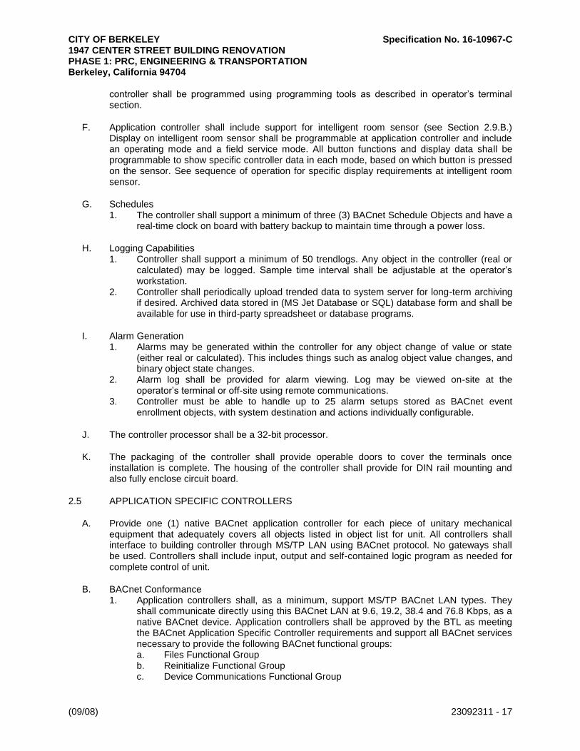
CITY OF BERKELEY Specification No. 16-10967-C 1947 CENTER STREET BUILDING RENOVATION PHASE 1: PRC, ENGINEERING & TRANSPORTATION Berkeley, California 94704
(09/08) 23092311 - 17
controller shall be programmed using programming tools as described in operator’s terminal section.
F. Application controller shall include support for intelligent room sensor (see Section 2.9.B.) Display on intelligent room sensor shall be programmable at application controller and include an operating mode and a field service mode. All button functions and display data shall be programmable to show specific controller data in each mode, based on which button is pressed on the sensor. See sequence of operation for specific display requirements at intelligent room sensor.
G. Schedules 1. The controller shall support a minimum of three (3) BACnet Schedule Objects and have a
real-time clock on board with battery backup to maintain time through a power loss.
H. Logging Capabilities 1. Controller shall support a minimum of 50 trendlogs. Any object in the controller (real or
calculated) may be logged. Sample time interval shall be adjustable at the operator’s workstation.
2. Controller shall periodically upload trended data to system server for long-term archiving if desired. Archived data stored in (MS Jet Database or SQL) database form and shall be available for use in third-party spreadsheet or database programs.
I. Alarm Generation 1. Alarms may be generated within the controller for any object change of value or state
(either real or calculated). This includes things such as analog object value changes, and binary object state changes.
2. Alarm log shall be provided for alarm viewing. Log may be viewed on-site at the operator’s terminal or off-site using remote communications.
3. Controller must be able to handle up to 25 alarm setups stored as BACnet event enrollment objects, with system destination and actions individually configurable.
J. The controller processor shall be a 32-bit processor.
K. The packaging of the controller shall provide operable doors to cover the terminals once installation is complete. The housing of the controller shall provide for DIN rail mounting and also fully enclose circuit board.
2.5 APPLICATION SPECIFIC CONTROLLERS
A. Provide one (1) native BACnet application controller for each piece of unitary mechanical equipment that adequately covers all objects listed in object list for unit. All controllers shall interface to building controller through MS/TP LAN using BACnet protocol. No gateways shall be used. Controllers shall include input, output and self-contained logic program as needed for complete control of unit.
B. BACnet Conformance 1. Application controllers shall, as a minimum, support MS/TP BACnet LAN types. They
shall communicate directly using this BACnet LAN at 9.6, 19.2, 38.4 and 76.8 Kbps, as a native BACnet device. Application controllers shall be approved by the BTL as meeting the BACnet Application Specific Controller requirements and support all BACnet services necessary to provide the following BACnet functional groups: a. Files Functional Group b. Reinitialize Functional Group c. Device Communications Functional Group

CITY OF BERKELEY Specification No. 16-10967-C 1947 CENTER STREET BUILDING RENOVATION PHASE 1: PRC, ENGINEERING & TRANSPORTATION Berkeley, California 94704
(09/08) 23092311 - 18
2. Please refer to Section 22.2, BACnet Functional Groups in the BACnet standard, for a complete list of the services that must be directly supported to provide each of the functional groups listed above. All proprietary services, if used in the system, shall be thoroughly documented and provided as part of the submittal data. All necessary tools shall be supplied for working with proprietary information.
3. Standard BACnet object types supported shall include, as a minimum, Analog Input, Analog Output, Analog Value, Binary Input, Binary Output, Binary Value, Device, File, and Program Object Types. All proprietary object types, if used in the system, shall be thoroughly documented and provided as part of the submittal data. All necessary tools shall be supplied for working with proprietary information.
C. Application controllers shall include universal inputs with 10-bit resolution that can accept 3K and 10K thermistors, 0–5VDC, 4–20mA, dry contact signals and a minimum of three (3) pulse inputs. Any input on controller may be either analog or digital. Controller shall also include support and modifiable programming for interface to intelligent room sensor. Controller shall include binary outputs on board with analog outputs as needed.
D. All program sequences shall be stored on board controller in EEPROM. No batteries shall be needed to retain logic program. All program sequences shall be executed by controller 10 times per second and shall be capable of multiple PID loops for control of multiple devices. Programming of application controller shall be completely modifiable in the field over installed BACnet LANs or remotely through modem interface. Operator shall program logic sequences by graphically moving function blocks on screen and tying blocks together on screen. Application controller shall be programmed using same programming tools as building controller and as described in operator workstation section. All programming tools shall be provided and installed as part of system.
E. Application controller shall include support for intelligent room sensor (see Section 2.9.B.) Display on room sensor shall be programmable at controller and include an operating mode and a field service mode. All button functions and display data shall be programmable to show specific controller data in each mode based on which button is pressed on the sensor. See sequence of operation for specific display requirements at intelligent room sensor.
2.6 ELECTRONIC ACTUATORS AND VALVES
A. Quality Assurance for Actuators and Valves 1. UL Listed Standard 873 and C.S.A. Class 4813 02 certified. 2. NEMA 2 rated enclosures for inside mounting, provide with weather shield for outside
mounting. 3. Five-year manufacturer’s warranty. Two-year unconditional and three-year product defect
from date of installation.
B. Execution Details for Actuators and Valves 1. VAV box damper and reheat valve actuation in addition to Fan Coil primary valve
actuation shall be floating type or analog (2–10 VDC, 4–20 mA). 2. Primary valve control on Air Handling Units shall be analog (2–10 VDC, 4–20 mA).
C. Actuators for damper and control valves 0.5–6 inches shall be electric unless otherwise specified, provide actuators as follows: 1. UL Listed Standard 873 and Canadian Standards Association Class 481302 shall certify
actuators. 2. NEMA 2 rated actuator enclosures for inside mounting. Use additional weather shield to
protect actuator when mounted outside.

CITY OF BERKELEY Specification No. 16-10967-C 1947 CENTER STREET BUILDING RENOVATION PHASE 1: PRC, ENGINEERING & TRANSPORTATION Berkeley, California 94704
(09/08) 23092311 - 19
3. Five-year manufacturer’s warranty. Two-year unconditional and three-year product defect from date of installation.
4. Mechanical spring shall be provided when specified. Capacitors or other non-mechanical forms of fail-safe are not acceptable.
5. Position indicator device shall be installed and made visible to the exposed side of the actuator. For damper short shaft mounting, a separate indicator shall be provided to the exposed side of the actuator.
6. Overload Protection: Actuators shall provide protection against actuator burnout by using an internal current limiting circuit or digital motor rotation sensing circuit. Circuit shall insure that actuators cannot burn out due to stalled damper or mechanical and electrical paralleling. End switches to deactivate the actuator at the end of rotation are acceptable only for butterfly valve actuators.
7. A pushbutton gearbox release shall be provided for all non-spring actuators. 8. Modulating actuators shall be 24 VAC and consume 10 VA power or less. 9. Conduit connectors are required when specified and when code requires it.
D. Damper Actuators 1. Economizer actuators shall utilize analog control 2–10 VDC; floating control is not
acceptable. 2. Electric damper actuators (including VAV box actuators) shall be direct shaft-mounted
and use a V-bolt and toothed V-clamp causing a cold weld effect for positive gripping. Single bolt or set-screw type fasteners are not acceptable.
3. One (1) electronic actuator shall be direct shaft-mounted per damper section. No connecting rods or jackshafts shall be needed. Small outside air and return air economizer dampers may be mechanically linked together if one (1) actuator has sufficient torque to drive both and damper drive shafts are both horizontal installed.
4. Multi-section dampers with electric actuators shall be arranged so that each damper section operates individually. One (1) electronic actuator shall be direct shaft-mounted per damper section. (See below execution section for more installation details.)
E. Valve Actuators 0.5–6 inches 1. All zone service actuators shall be non-spring return unless otherwise specified. 2. The valve actuator shall be capable of providing the minimum torque required for proper
valve close-off for the required application. 3. All control valves actuators shall have an attached 3-foot cable for easy installation to a
junction box. 4. Override handle and gearbox release shall be provided for all non-spring return valve
actuators.
F. Control Valves 0.5–6 inches 1. The BAS contractor shall furnish all specified motorized control valves and actuators.
BAS contractor shall furnish all control wiring to actuators. The plumbing contractor shall install all valves. Equal percentage control characteristic shall be provided for all water coil control valves. Linear valve characteristic is acceptable for 3-way valves that are 2.5 inches and above.
2. Characterized control valves shall be used for hydronic heating or cooling applications and small to medium AHU water-coil applications to 100GPM. Actuators are non-spring return for terminal unit coil control unless otherwise noted. If the coil is exposed to the outside air stream, see plans for spring return requirement. a. Leakage is 0% (zero percent), close-off is 200psi, maximum differential is 30psi;
rangeablity is 500:1. b. Valves 0.5–2 inches shall be nickel-plated forged brass body, NPT screw type
connections.

CITY OF BERKELEY Specification No. 16-10967-C 1947 CENTER STREET BUILDING RENOVATION PHASE 1: PRC, ENGINEERING & TRANSPORTATION Berkeley, California 94704
(09/08) 23092311 - 20
c. Valves 0.5–1.25 inches shall be rated for ANSI Class 600 working pressure. Valves 1.5 and 2 inches shall be rated for ANSI Class 400 working pressure.
d. The operating temperature range shall be 0–250 degrees F. e. Stainless steel ball and stem shall be furnished on all modulating valves. f. Seats shall be fiberglass reinforced Teflon. g. Two-way and three-way valves shall have an equal percentage control port. Full
stem rotation is required for maximum flow to insure stable BTU control of the coil. h. Three-way valve shall be applicable for both mixing and diverting. i. The characterizing disc is made of TEFZEL and shall be keyed and held secure by
a retaining ring. j. The valves shall have a blow-out proof stem design. k. The stem packing shall consist of two (2) lubricated O-rings designed for on-off or
modulating service and require no maintenance. l. The valves shall have an ISO type, 4-bolt flange for mounting actuator in any
orientation parallel or perpendicular to the pipe. m. A non-metallic thermal isolation adapter shall separate valve flange from actuator. n. One (1) fastening screw shall secure the direct coupling of the thermal isolation
adapter between the actuator and the valve. This will prevent all lateral or rotational forces from affecting the stem and its packing O-rings.
3. Globe valves 0.5–2 inches shall be used for steam control or water flow applications. a. Valves shall be bronze body, NPT screw type, and shall be rated for ANSI Class
250 working pressure. b. Valves 0.5 inches (DN15) through 2 inches (DN50) with spring return actuators
shall close off against 50 psi pressure differential with Class III leakage (0.1%). c. The operating temperature range shall be 20–280 degrees F. d. Spring loaded TFE packing shall protect against leakage at the stem. e. Two-way valves shall have an equal percentage control port. f. Three-way valves shall have a linear control and bypass port. g. Mixing and diverting valves must be installed specific to the valve design.
4. Globe Valves 2.5–6 inches a. Valves 2.5 inches (DN65) through 6 inches (DN50) shall be iron body, 125 lb.
flanged with Class III (0.1%) close-off leakage at 50 psi differential. b. Valves with spring return actuators shall close off against 50 psi pressure
differential with Class III leakage (0.1%). c. Flow type for two-way valves shall be equal percentage. Flow type for three-way
valves shall be linear. d. Mixing and diverting valves must be installed specific to the valve design.
G. Butterfly valves 1. Butterfly valves shall be sized for modulating service at 60–70 degree stem rotation. Iso-
lation valves shall be line-size. Design velocity shall be less than 12 feet per second when used with standard EPDM seats. a. Body is cast iron. b. Disc is aluminum bronze standard. c. Seat is EPDM standard. d. Body Pressure is 200 psi, -30–275 degrees F. e. Flange is ANSI 125/250. f. Media Temperature Range is -22–240 degree F. g. Maximum Differential Pressure is 200 psi for 2- to 6- inch size.
H. Butterfly Valve Industrial Actuators 1. Actuators shall be approved under Canadian Standards Association or other Nationally
Recognized Testing Laboratory to UL standards. CSA Class 4813 02 or equal. Enclosure shall be NEMA 4 (weatherproof) enclosure and will have an industrial quality coating.

CITY OF BERKELEY Specification No. 16-10967-C 1947 CENTER STREET BUILDING RENOVATION PHASE 1: PRC, ENGINEERING & TRANSPORTATION Berkeley, California 94704
(09/08) 23092311 - 21
a. Actuator shall have a motor rated for continuous duty. The motor shall be fractional horsepower; permanent split capacitor type designed to operate on a 120 VAC, 1pH, 60 Hz supply. Two (2) adjustable cam-actuated end travel limit switches shall be provided to control direction of travel. A self-resetting thermal switch shall be imbedded in the motor for overload protection.
b. Reduction gearing shall be designed to withstand the actual motor stall torque. Gears shall be hardened alloy steel, permanently lubricated. A self-locking gear assembly or a brake shall be supplied.
c. Actuator shall have a 6-foot wiring harness provided for ease in field wiring (above 1500 in-lbs). Two (2) adjustable SPDT cam-actuated auxiliary switches, rated at 250 VAC shall be provided for indication of open and closed position. Actuator shall have heater and thermostat to minimize condensation within the actuator housing.
d. Actuator shall be equipped with a hand wheel for manual override to permit operation of the valve in the event of electrical power failure or system malfunction. Hand wheel must be permanently attached to the actuator and when in manual operation electrical power to the actuator will be permanently interrupted. The hand wheel will not rotate while the actuator is electrically driven.
e. The actuator shall be analog, floating, or two position as called out in the control sequence of operation. All Analog valves shall be positive positioning, and respond to a 2–10 VDC, 4-20 mA, or adjustable signal as required. Analog actuators shall have a digital control card allowing any voltage input for control and any DC voltage feedback signal for position indication.
2. Performance Verification Test a. Control loops shall cause productive actuation with each movement of the actuator
and actuators shall modulate at a rate that is stable and responsive. Actuator movement shall not occur before the effects of previous movement have affected the sensor.
b. Actuator shall have capability of signaling a trouble alarm when the actuator Stop-Go Ratio exceeds 30%.
3. Actuator mounting for damper and valve arrangements shall comply with the following: a. Damper actuators: Shall not be installed in the air stream. b. A weather shield shall be used if actuators are located outside. For damper
actuators, use clear plastic enclosure. c. Damper or valve actuator ambient temperature shall not exceed 122 degrees F
through any combination of medium temperature or surrounding air. Appropriate air gaps, thermal isolation washers or spacers, standoff legs, or insulation shall be provided as necessary.
d. Actuator cords or conduit shall incorporate a drip leg if condensation is possible. Water shall not be allowed to contact actuator or internal parts. Location of conduits in temperatures dropping below dew point shall be avoided to prevent water from condensing in conduit and running into actuator.
e. Damper mounting arrangements shall comply to the following: 1) The ventilation subcontractor shall furnish and install damper channel
supports and sheet metal collars. 2) No jack shafting of damper sections shall be allowed. 3) Multi-section dampers shall be arranged so that each damper section
operates individually. One (1) electronic actuator shall be direct shaft mounted per section.
f. Size damper sections based on actuator manufacturer’s specific recommendations for face velocity, differential pressure and damper type. In general: 1) Damper section shall not exceed 24 ft-sq. with face velocity >1500 FPM. 2) Damper section shall not exceed 18 ft-sq. with face velocity > 2500 FPM. 3) Damper section shall not exceed 13 ft-sq. with face velocity > 3000 FPM.

CITY OF BERKELEY Specification No. 16-10967-C 1947 CENTER STREET BUILDING RENOVATION PHASE 1: PRC, ENGINEERING & TRANSPORTATION Berkeley, California 94704
(09/08) 23092311 - 22
f. Multiple section dampers of two or more shall be arranged to allow actuators to be direct shaft mounted on the outside of the duct.
g. Multiple section dampers of three or more sections wide shall be arranged with a 3-sided vertical channel (8 inches wide by 6 inches deep) within the duct or fan housing and between adjacent damper sections. Vertical channel shall be anchored at the top and bottom to the fan housing or building structure for support. The sides of each damper frame shall be connected to the channels. Holes in the channel shall allow damper drive blade shafts to pass through channel for direct shaft-mounting of actuators. Open side of channel shall be faced downstream of the airflow, except for exhaust air dampers.
h. Multiple section dampers to be mounted flush within a wall or housing opening shall receive either vertical channel supports as described above or sheet metal standout collars. Sheet metal collars (12-inch minimum) shall bring each damper section out of the wall to allow direct shaft-mounting of the actuator on the side of the collar.
4. Valve Sizing for Water Coil a. On/Off control valves shall be line-size. b. Modulating control valve body size may be reduced, at most, two (2) pipe sizes
from the line size or not less than half the pipe size. The BAS contractor shall size all water coil control valves for the application as follows: 1) Booster-heat valves shall be sized not to exceed 4–9psi differential
pressure. Size valve for 50% valve authority. Valve design pressure drop is equal to the sum of coil drop plus the balance valve drop.
2) Primary valves shall be sized not to exceed 5–15psi differential pressure. Size valve for 50% valve authority. Valve design pressure drop is equal to the sum of coil drop plus the balance valve drop.
3) Butterfly valves shall be sized for modulating service at 60–70 degree rotation. Design velocity shall be 12 feet per second or less when used with standard EPDM seats.
c. Valve mounting arrangements shall comply with the following: 1) Unions shall be provided on all ports of two-way and three-way valves. 2) Install three-way equal percentage characterized control valves in a mixing
configuration with the “A” port piped to the coil. 3) Install 2.5 inches and above, three-way globe valves, as manufactured for
mixing or diverting service to the coil.
2.7 ENCLOSURES
A. All controllers, power supplies and relays shall be mounted in enclosures.
B. Enclosures may be NEMA 1 when located in a clean, dry, indoor environment. Indoor enclosures shall be NEMA 12 when installed in other than a clean environment. Outdoor enclosures must be either NEMA 3R or NEMA 4.
C. All temperature control panels shall be fabricated in a UL-listed panel shop. Field assembled temperature control panels are not allowed.
PART 3 - EXECUTION
3.1 EXAMINATION
A. Prior to starting work, carefully inspect installed work of other trades and verify that such work is complete to the point where work of this section may properly commence.

CITY OF BERKELEY Specification No. 16-10967-C 1947 CENTER STREET BUILDING RENOVATION PHASE 1: PRC, ENGINEERING & TRANSPORTATION Berkeley, California 94704
(09/08) 23092311 - 23
B. Notify the owner’s representative in writing of conditions detrimental to the proper and timely completion of the work.
C. Do not begin work until all unsatisfactory conditions are resolved.
3.2 INSTALLATION (GENERAL)
A. Install in accordance with manufacturer's instructions.
B. Provide all miscellaneous devices, hardware, software, interconnections, installation, and programming required to ensure a complete operating system in accordance with the sequences of operation and point schedules.
3.3 LOCATION AND INSTALLATION OF COMPONENTS
A. Locate and install components for easy accessibility; in general, mount 48 inches above floor with minimum three (3) feet of clear access space in front of units. Obtain approval on locations from owner’s representative prior to installation.
B. All instruments, switches, transmitters, etc., shall be suitably wired and mounted to protect them from vibration, moisture, and high or low temperatures.
C. Identify all equipment and panels. Provide permanently mounted tags for all panels.
D. Provide stainless steel or brass thermowells suitable for respective application and for installation under other sections, and sized to suit pipe diameter without restricting flow.
3.4 INTERLOCKING AND CONTROL WIRING
A. Provide all interlock and control wiring associated with the EMS system. All wiring shall be installed neatly and professionally, in accordance with all national, state and local electrical codes.
B. Provide wiring as required by functions as specified and as recommended by equipment manufacturers, to serve specified control functions. Provide shielded low capacitance wire for all communications trunks.
C. Control wiring shall not be installed in power circuit raceways. Magnetic starters and disconnect switches shall not be used as junction boxes. Provide auxiliary junction boxes as required. Coordinate location and arrangement of all control equipment with the owner's representative prior to rough-in.
D. Provide auxiliary pilot duty relays on motor starters as required for control function.
E. Provide power for all control components from nearest electrical control panel or as indicated on the electrical drawings; coordinate with electrical contractor.
F. All control wiring in mechanical, electrical, telephone and boiler rooms to be installed in raceways. Exposed control wiring shall also be installed in raceways. All other control wiring to be installed without conduit neatly and inconspicuously per local code requirements.

CITY OF BERKELEY Specification No. 16-10967-C 1947 CENTER STREET BUILDING RENOVATION PHASE 1: PRC, ENGINEERING & TRANSPORTATION Berkeley, California 94704
(09/08) 23092311 - 24
3.5 DDC OBJECT TYPE SUMMARY
A. Provide all database generation.
B. Displays 1. System displays shall show all analog and binary object types within the system. They
shall be logically laid out for easy use by the owner. Provide outside air temperature indi-cation on all system displays associated with economizer cycles.
C. Run Time Totalization 1. At a minimum, run time totalization shall be incorporated for each monitored supply fan,
return fan, exhaust fan, hot water and chilled water pumps. Warning limits for each point shall be entered for alarm and or maintenance purposes.
D. Trendlog 1. All binary and analog object types (including zones) shall have the capability to be
automatically trended.
E. Alarm 1. All analog inputs (High/Low Limits) and selected binary input alarm points shall be priori-
tized and routed (locally or remotely) with alarm message per owner's requirements.
F. Database Save 1. Provide backup database for all standalone application controllers on disk.
3.6 FIELD SERVICES
A. Prepare and start logic control system under provisions of this section.
B. Start up and commission systems. Allow sufficient time for startup and commissioning prior to placing control systems in permanent operation.
C. Provide the capability for off-site monitoring at control contractor's local or main office. At a minimum, off-site facility shall be capable of system diagnostics and software download. Owner shall provide phone line for this service for one (1) year or as specified.
D. Provide owner's representative with spare parts list. Identify equipment critical to maintaining the integrity of the operating system.
3.7 TRAINING
A. Provide application engineer to instruct owner in operation of systems and equipment.
B. Provide system operator’s training to include (but not be limited to) such items as the following: modification of data displays, alarm and status descriptors, requesting data, execution of commands and request of logs. Provide this training to a minimum of three persons.
C. Provide on-site training above as required, up to 16 hours as part of this contract.

CITY OF BERKELEY Specification No. 16-10967-C 1947 CENTER STREET BUILDING RENOVATION PHASE 1: PRC, ENGINEERING & TRANSPORTATION Berkeley, California 94704
(09/08) 23092311 - 25
3.8 DEMONSTRATION
A. Demonstrate complete operating system to owner's representative.
B. Provide certificate stating that control system has been tested and adjusted for proper operation.
END OF SECTION

CITY OF BERKELEY Specification No. 16-10967-C 1947 CENTER STREET BUILDING RENOVATION PHASE 1: PRC, ENGINEERING & TRANSPORTATION Berkeley, California 94704
Control Valves (08-01) 230923.11 - 1
SECTION 23 09 23.11
CONTROL VALVES
PART 1 - GENERAL
1.1 RELATED DOCUMENTS
A. Drawings and general provisions of the Contract, including General and Supplementary Conditions and Division 01 Specification Sections, apply to this Section.
1.2 SUMMARY
A. Section includes control valves and actuators for DDC systems.
B. Related Requirements: 1. Section 230923 "Direct-Digital Control System for HVAC" control equipment and
software, relays, electrical power devices, uninterruptible power supply units, wire, and cable.
2. Section 230933 "Electric and Electronic Control System for HVAC" for electric/electronic control valves and actuators in electric and electronic control systems.
3. Section 230943 "Pneumatic Control System for HVAC" for pneumatic control valves and actuators in pneumatic control systems.
4. Section 230993 "Sequence of Operations for HVAC Controls" for requirements that relate to Section 230923.11.
1.3 DEFINITIONS
A. Cv: Design valve coefficient.
B. DDC: Direct-digital control.
C. NBR: Nitrile butadiene rubber.
D. PTFE: Polytetrafluoroethylene
E. RMS: Root-mean-square value of alternating voltage, which is the square root of the mean value of the square of the voltage values during a complete cycle.
1.4 ACTION SUBMITTALS
A. Product Data: For each type of product, including the following: 1. Construction details, material descriptions, dimensions of individual components and
profiles, and finishes. 2. Operating characteristics, electrical characteristics, and furnished accessories indicating
process operating range, accuracy over range, control signal over range, default control signal with loss of power, calibration data specific to each unique application, electrical power requirements, and limitations of ambient operating environment, including temperature and humidity.

CITY OF BERKELEY Specification No. 16-10967-C 1947 CENTER STREET BUILDING RENOVATION PHASE 1: PRC, ENGINEERING & TRANSPORTATION Berkeley, California 94704
Control Valves (08-01) 230923.11 - 2
3. Product description with complete technical data, performance curves, and product specification sheets.
4. Installation, operation, and maintenance instructions, including factors affecting performance.
B. Shop Drawings: 1. Include plans, elevations, sections, and mounting details. 2. Include details of product assemblies. Indicate dimensions, weights, loads, required
clearances, method of field assembly, components, and location and size of each field connection.
3. Include diagrams for power, signal, and control wiring. 4. Include diagrams for pneumatic signal and main air tubing.
C. Delegated-Design Submittal: 1. Schedule and design calculations for control valves and actuators, including the
following: a. Flow at project design and minimum flow conditions. b. Pressure differential drop across valve at project design flow condition. c. Maximum system pressure differential drop (pump close-off pressure) across valve
at project minimum flow condition. d. Design and minimum control valve coefficient with corresponding valve position. e. Maximum close-off pressure. f. Leakage flow at maximum system pressure differential. g. Torque required at worst case condition for sizing actuator. h. Actuator selection indicating torque provided.
1.5 INFORMATIONAL SUBMITTALS
A. Coordination Drawings: Plan drawings and corresponding product installation details, drawn to scale, on which the following items are shown and coordinated with each other, using input from installers of the items involved: 1. Control valve installation location shown in relationship to room, duct, pipe, and
equipment. 2. Size and location of wall access panels for control valves installed behind walls. 3. Size and location of ceiling access panels for control valves installed above inaccessible
ceilings.
1.6 CLOSEOUT SUBMITTALS
A. Operation and Maintenance Data: For control valves to include in operation and maintenance manuals.
PART 2 - PRODUCTS
2.1 PERFORMANCE REQUIREMENTS
A. Electrical Components, Devices, and Accessories: Listed and labeled as defined in NFPA 70, by a qualified testing agency, and marked for intended location and application.
B. ASME Compliance: Fabricate and label products to comply with ASME Boiler and Pressure Vessel Code where required by authorities having jurisdiction.

CITY OF BERKELEY Specification No. 16-10967-C 1947 CENTER STREET BUILDING RENOVATION PHASE 1: PRC, ENGINEERING & TRANSPORTATION Berkeley, California 94704
Control Valves (08-01) 230923.11 - 3
C. Delegated Design: Engage a qualified professional engineer, as defined in Section 014000 "Quality Requirements," to size products where indicated as delegated design.
D. Ground Fault: Products shall not fail due to ground fault condition when suitably grounded.
E. Backup Power Source: Systems and equipment served by a backup power source shall have associated control valve actuators served from a backup power source.
F. Environmental Conditions: 1. Provide electric control valve actuators, with protective enclosures satisfying the following
minimum requirements unless more stringent requirements are indicated. Electric control valve actuators not available with integral enclosures, complying with requirements indicated, shall be housed in protective secondary enclosures. a. Hazardous Locations: Explosion-proof rating for condition.
G. Determine control valve sizes and flow coefficients by ISA 75.01.01.
H. Control valve characteristics and rangeability shall comply with ISA 75.11.01.
I. Selection Criteria: 1. Control valves shall be suitable for operation at following conditions:
a. Heating Hot Water: 30 psi and 180 F. 2. Control valve shutoff classifications shall be FCI 70-2, Class IV or better unless otherwise
indicated. 3. Valve pattern, three-way or straight through, shall be as indicated on Drawings. 4. Modulating straight-through pattern control valves shall have equal percentage flow-
throttling characteristics unless otherwise indicated. 5. Modulating three-way pattern water valves shall have linear flow-throttling characteristics.
The total flow through the valve shall remain constant regardless of the valve's position. 6. Modulating butterfly valves shall have [linear] [or] [equal percentage] flow-throttling
characteristics. 7. Fail positions unless otherwise indicated:
a. Condenser Water: Open. b. Heating Hot Water: Open. c. Steam: [Close] [Last position] [Open].
8. Globe-type control valves shall pass the design flow required with not more than 95 percent of stem lift unless otherwise indicated.
9. Rotary-type control valves, such as ball and butterfly valves, shall have Cv falling between 65 and 75 degrees of valve full open position and minimum valve Cv between 15 and 25 percent of open position.
10. Selection shall consider viscosity, flashing, and cavitation corrections. 11. Valves shall have stable operation throughout full range of operation, from design to
minimum Cv. 12. Minimum Cv shall be calculated at 10 percent of design flow, with a coincident pressure
differential equal to the system design pump head. 13. In water systems, select modulating control valves at terminal equipment for a design Cv
based on a pressure drop of 5 psig at design flow unless otherwise indicated. 14. Modulating valve sizes for steam service shall provide a pressure drop at design flow
equal to lesser of the following: a. 50 percent of the valve inlet pressure.
15. Two-position control valves shall be line size unless otherwise indicated.

CITY OF BERKELEY Specification No. 16-10967-C 1947 CENTER STREET BUILDING RENOVATION PHASE 1: PRC, ENGINEERING & TRANSPORTATION Berkeley, California 94704
Control Valves (08-01) 230923.11 - 4
16. In water systems, use ball- or globe-style control valves for two-position control for valves NPS 2 and smaller and butterfly style for valves larger than NPS 2.
17. In steam systems, use ball- or globe-style control valves regardless of size. 18. Pneumatic, two-position control valves shall provide a smooth opening and closing
characteristic slow enough to avoid water hammer. Valves with pneumatic actuators shall have an adjustable opening time (valve full closed to full open) and an adjustable closing time (valve full open to full closed) ranging from zero to 10 seconds. Opening and closing times shall be independently adjustable.
19. Control valve, pneumatic-control signal shall not exceed 200 feet. For longer distances, provide an electric/electronic control signal to the valve and an electric solenoid valve or electro-pneumatic transducer at the valve to convert the control signal to pneumatic.
2.2 BALL-STYLE CONTROL VALVES
A. Ball Valves with Single Port and Characterized Disk: 1. Manufacturers: Subject to compliance with requirements, available manufacturers
offering products that may be incorporated into the Work include, but are not limited to the following: a. Belimo Aircontrols (USA), Inc.
2. Pressure Rating for NPS 1 and Smaller: Nominal 600 WOG. 3. Pressure Rating for NPS 1-1/2 through NPS 2: Nominal 400 WOG. 4. Close-off Pressure: 200 psig. 5. Process Temperature Range: Zero to 212 deg F. 6. Body and Tail Piece: Cast bronze ASTM B 61, ASTM B 62, ASTM B 584, or forged brass
with nickel plating. 7. End Connections: Threaded (NPT) ends. 8. Ball: [Chrome-plated brass or bronze] [or] [300 series stainless steel]. 9. Stem and Stem Extension:
a. Material to match ball. b. Blowout-proof design. c. Sleeve or other approved means to allow valve to be opened and closed without
damaging the insulation or the vapor barrier seal. 10. Ball Seats: Reinforced PTFE. 11. Stem Seal: Reinforced PTFE packing ring with a threaded packing ring follower to retain
the packing ring under design pressure with the linkage removed. Alternative means, such as EPDM O-rings, are acceptable if an equivalent cycle endurance can be demonstrated by testing.
12. Flow Characteristic: Equal percentage.
B. Ball Valves with Two Ports and Characterized Disk: 1. Manufacturers: Subject to compliance with requirements, available manufacturers
offering products that may be incorporated into the Work include, but are not limited to the following: a. Belimo Aircontrols (USA), Inc.
2. Pressure Rating for NPS 1 and Smaller: Nominal 600 WOG. 3. Pressure Rating for NPS 1-1/2 through NPS 2: Nominal 400 WOG. 4. Close-off Pressure: 200 psig. 5. Process Temperature Range: Zero to 212 deg F. 6. Body and Tail Piece: Cast bronze ASTM B 61, ASTM B 62, ASTM B 584, or forged brass
with nickel plating. 7. End Connections: Threaded (NPT) ends. 8. Ball: [Chrome-plated brass or bronze] [or] [300 series stainless steel].

CITY OF BERKELEY Specification No. 16-10967-C 1947 CENTER STREET BUILDING RENOVATION PHASE 1: PRC, ENGINEERING & TRANSPORTATION Berkeley, California 94704
Control Valves (08-01) 230923.11 - 5
9. Stem and Stem Extension: a. Material to match ball. b. Blowout-proof design. c. Sleeve or other approved means to allow valve to be opened and closed without
damaging the insulation or the vapor barrier seal. 10. Ball Seats: Reinforced PTFE. 11. Stem Seal: Reinforced PTFE packing ring with a threaded packing ring follower to retain
the packing ring under design pressure with the linkage removed. Alternative means, such as EPDM O-rings, are acceptable if an equivalent cycle endurance can be demonstrated by testing.
12. Flow Characteristics for A-Port: Equal percentage. 13. Flow Characteristics for B-Port: Modified for constant common port flow.
C. Ball Valves with Single Port and Segmented Ball: 1. Manufacturers: Subject to compliance with requirements, available manufacturers
offering products that may be incorporated into the Work include, but are not limited to the following: a. Valve Solutions, Inc.
2. Performance: a. Process Temperature Rating: Minus 20 to plus 450 deg F. b. ASME B16.34, [Class 150] [or] [Class 300]. c. Leakage: FCI 70-2, Class IV. d. Rangeability: 300 to 1. e. Rotation: Zero to 90 degrees. f. Equal percentage flow characteristic.
3. ASME B16.10 face-to-face dimensions. 4. Valves NPS 2 and Smaller: Threaded (NPT) ends. 5. Valves NPS 2-1/2 through NPS 6: Flanged ends suitable for mating to ASME B16.5
flanges. 6. Body: [Carbon] [or] [stainless] steel. 7. Ball and Shaft: Stainless steel. 8. Shaft and Segmented Ball: Pinned and welded. 9. Ball Seat: Graphite. 10. Packing: PTFE V-rings and graphite packing follower. 11. Replaceable seat, ball, and shaft packing. 12. Label each valve with following:
a. Manufacturer's name, model number, and serial number. b. Body size. c. Flow directional arrow.
D. Ball Valves with Segmented Ball, Three-Way Pattern: 1. Manufacturers: Subject to compliance with requirements, available manufacturers
offering products that may be incorporated into the Work include, but are not limited to the following: a. Valve Solutions, Inc.
2. Arrangement: Two single-port valves mated to a fabricated tee with interconnecting mechanical linkage.
3. Performance: a. Process Temperature Rating: Minus 20 to plus 450 deg F. b. ASME B16.34, [Class 150] [or] [Class 300]. c. Leakage: FCI 70-2, Class IV. d. Rangeability: 300 to 1.

CITY OF BERKELEY Specification No. 16-10967-C 1947 CENTER STREET BUILDING RENOVATION PHASE 1: PRC, ENGINEERING & TRANSPORTATION Berkeley, California 94704
Control Valves (08-01) 230923.11 - 6
e. Rotation: Zero to 90 degrees. f. Equal percentage flow characteristic.
4. Face-to-Face Dimensions: ASME B16.10. 5. Valves NPS 3through NPS 6: Flanged ends suitable for mating to ASME B16.5 flanges. 6. Body: [Carbon] [or] [stainless] steel. 7. Ball and Shaft: Stainless steel. 8. Shaft and Segmented Ball: Pinned and welded. 9. Ball Seat: Graphite. 10. Packing: PTFE V-rings and graphite packing follower. 11. Replaceable seat, ball, and shaft packing. 12. Label each valve with following:
a. Manufacturer's name, model number, and serial number. b. Body size. c. Flow directional arrow.
E. Ball Valves with Full Ball and Characterized V-Notch: 1. Manufacturers: Subject to compliance with requirements, available manufacturers
offering products that may be incorporated into the Work include, but are not limited to the following: a. Flow-Tek, Inc.
2. Performance: a. Process Temperature Rating: Minus 20 to plus 500 deg F. b. ASME B16.34, Class 600 for NPS 2 and smaller; [Class 150] [or] [Class 300] for
larger than NPS 2. c. Leakage: FCI 70-2, Class VI, bi-directional. d. Rangeability: Varies from 200 to 1 up to 800 to 1 based on notch pattern of ball. e. Rotation: Zero to 90 degrees. f. Equal percentage flow characteristic. g. Full port.
3. Face-to-Face Dimension: ASME B16.10 long pattern. 4. Valves NPS 2 and Smaller: ASME B1.20.1 threaded (NPT) ends and three-piece body. 5. Valves NPS 2-1/2 through NPS 12: Flanged ends suitable for mating to ASME B16.5
flanges and two-piece body. 6. Hole in the stem slot of each ball equalizes pressure between the body cavity and the line
media flow. 7. Replaceable seat, ball, and shaft packing. 8. Body: [Carbon] [or] [stainless] steel. 9. Ball and Shaft: Stainless steel. 10. Ball Seat: RPTFE. 11. Stem Seals for Valves NPS 2 and Smaller: Live-loaded, self-adjusting, primary and
secondary sealing using belleville washers. a. Primary Seal: Combination of thrust washer and thrust washer protector. b. Secondary Seal: Adjustable stem packing composed of RPTFE V-rings.
12. Stem Seals for Valves Larger than NPS 2: Independent packing gland, adjusted without removing mounting hardware or operator, and contoured to uniformly distribute load across packing. a. Primary Seal: Combination of thrust washer and thrust washer protector. b. Secondary Seal: Adjustable stem packing composed of RPTFE V-rings.
13. Label each valve with following: a. Manufacturer's name, model number, and serial number. b. Body size. c. Flow directional arrow.

CITY OF BERKELEY Specification No. 16-10967-C 1947 CENTER STREET BUILDING RENOVATION PHASE 1: PRC, ENGINEERING & TRANSPORTATION Berkeley, California 94704
Control Valves (08-01) 230923.11 - 7
F. Industrial-Grade Ball Valves: 1. Manufacturers: Subject to compliance with requirements, available manufacturers
offering products that may be incorporated into the Work include, but are not limited to the following: a. Fisher Valves & Instruments; Emerson Process Management.
2. Performance: a. Process Temperature Rating: Minus 20 to plus 450 deg F. b. ASME B16.34, [Class 150] [or] [Class 300]. c. Leakage: FCI 70-2, Class VI. d. Rangeability: 300 to 1. e. Rotation: Zero to 90 degrees. f. Modified equal percentage flow characteristic.
3. Face-to-Face Dimensions: Comply with ASME B16.10 short pattern. 4. Body: Cast steel ASTM A 216/A 216M WCB. 5. Flanged Body: Suitable for mating to ASME B16.5 flanges. 6. Shaft: 316 stainless-steel ball, 17-4 PH stainless steel. 7. Ball Seat: Reinforced PTFE. 8. PTFE V-ring packing, 316 stainless-steel packing follower. 9. Replaceable seat, ball, and shaft packings. 10. Replaceable 316 stainless-steel shaft bushings with PTFE linings. 11. Corrosion-resistant nameplate indicating the following:
a. Manufacturer's name, model number, and serial number. b. Body size. c. Body and trim materials. d. Trim type. e. Body and flange rating. f. Arrow indicating direction of flow.
G. Pressure-Independent Ball Valves NPS 2 and Smaller: 1. Manufacturers: Subject to compliance with requirements, available manufacturers
offering products that may be incorporated into the Work include, but are not limited to the following: a. Belimo Aircontrols (USA), Inc. b. HCI; Hydronics Components Inc.
2. Performance: a. Pressure Rating: 600 psig for NPS 1 and 400 psig for NPS 1-1/2 and NPS 2. b. Close-off pressure of 200 psig. c. Process Temperature Range: Between zero to 212 deg F. d. Rangeability: 100 to 1.
3. Integral Pressure Regulator: Located upstream of ball to regulate pressure, to maintain a constant pressure differential while operating within a pressure differential range of 5 to 50 psig.
4. Body: Forged brass, nickel plated, and with threaded ends. 5. Ball: Chrome-plated brass. 6. Stem and Stem Extension: Chrome-plated brass, blowout-proof design. 7. Stem sleeve or other approved means to allow valve to be opened and closed without
damaging field-applied insulation and insulation vapor barrier seal. 8. Ball Seats: Reinforced PTFE. 9. Stem Seal: Reinforced PTFE packing ring stem seal with threaded packing ring follower
to retain the packing ring under design pressure with the linkage removed. Alternative means, such as EPDM O-rings, are acceptable if equivalent cycle endurance can be achieved.

CITY OF BERKELEY Specification No. 16-10967-C 1947 CENTER STREET BUILDING RENOVATION PHASE 1: PRC, ENGINEERING & TRANSPORTATION Berkeley, California 94704
Control Valves (08-01) 230923.11 - 8
10. Flow Characteristic: Equal percentage.
2.3 GLOBE-STYLE CONTROL VALVES
A. General Globe-Style Valve Requirements: 1. Globe-style control valve body dimensions shall comply with ISA 75.08.01. 2. Construct the valves to be serviceable from the top. 3. For cage guided valves, trim shall be field interchangeable for different valve flow
characteristics, such as equal percentage, linear, and quick opening. 4. Reduced trim for one nominal size smaller shall be available for industrial valves NPS 1
and larger. 5. Replaceable seats and plugs. 6. Furnish each control valve with a corrosion-resistant nameplate indicating the following:
a. Manufacturer's name, model number, and serial number. b. Body and trim size. c. Arrow indicating direction of flow.
2.4 ELECTRIC AND ELECTRONIC CONTROL VALVE ACTUATORS
A. Actuators for Hydronic Control Valves: Capable of closing valve against system pump shutoff head.
B. .
C. Position indicator and graduated scale on each actuator.
D. Type: Motor operated, with or without gears, electric and electronic.
E. Voltage: Voltage selection delegated to professional designing control system24-V ac.
F. Deliver torque required for continuous uniform movement of controlled device from limit to limit when operated at rated voltage.
G. Function properly within a range of 85 to 120 percent of nameplate voltage.
H. Construction: 1. For Actuators Less Than 100 W: Fiber or reinforced nylon gears with steel shaft, copper
alloy or nylon bearings, and pressed steel enclosures. 2. For Actuators from 100 to 400 W: Gears ground steel, oil immersed, shaft hardened steel
running in bronze, copper alloy or ball bearings. Operator and gear trains shall be totally enclosed in dustproof cast-iron, cast-steel or cast-aluminum housing.
3. For Actuators Larger Than 400 W: Totally enclosed reversible induction motors with auxiliary hand crank and permanently lubricated bearings.
I. Field Adjustment: 1. Spring Return Actuators: Easily switchable from fail open to fail closed in the field without
replacement. 2. Gear Type Actuators: External manual adjustment mechanism to allow manual
positioning when the actuator is not powered.
J. Two-Position Actuators: Single direction, spring return or reversing type.
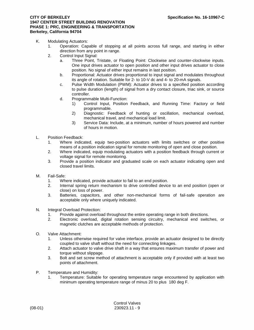
CITY OF BERKELEY Specification No. 16-10967-C 1947 CENTER STREET BUILDING RENOVATION PHASE 1: PRC, ENGINEERING & TRANSPORTATION Berkeley, California 94704
Control Valves (08-01) 230923.11 - 9
K. Modulating Actuators: 1. Operation: Capable of stopping at all points across full range, and starting in either
direction from any point in range. 2. Control Input Signal:
a. Three Point, Tristate, or Floating Point: Clockwise and counter-clockwise inputs. One input drives actuator to open position and other input drives actuator to close position. No signal of either input remains in last position.
b. Proportional: Actuator drives proportional to input signal and modulates throughout its angle of rotation. Suitable for 2- to 10-V dc and 4- to 20-mA signals.
c. Pulse Width Modulation (PWM): Actuator drives to a specified position according to pulse duration (length) of signal from a dry contact closure, triac sink, or source controller.
d. Programmable Multi-Function: 1) Control Input, Position Feedback, and Running Time: Factory or field
programmable. 2) Diagnostic: Feedback of hunting or oscillation, mechanical overload,
mechanical travel, and mechanical load limit. 3) Service Data: Include, at a minimum, number of hours powered and number
of hours in motion.
L. Position Feedback: 1. Where indicated, equip two-position actuators with limits switches or other positive
means of a position indication signal for remote monitoring of open and close position. 2. Where indicated, equip modulating actuators with a position feedback through current or
voltage signal for remote monitoring. 3. Provide a position indicator and graduated scale on each actuator indicating open and
closed travel limits.
M. Fail-Safe: 1. Where indicated, provide actuator to fail to an end position. 2. Internal spring return mechanism to drive controlled device to an end position (open or
close) on loss of power. 3. Batteries, capacitors, and other non-mechanical forms of fail-safe operation are
acceptable only where uniquely indicated.
N. Integral Overload Protection: 1. Provide against overload throughout the entire operating range in both directions. 2. Electronic overload, digital rotation sensing circuitry, mechanical end switches, or
magnetic clutches are acceptable methods of protection.
O. Valve Attachment: 1. Unless otherwise required for valve interface, provide an actuator designed to be directly
coupled to valve shaft without the need for connecting linkages. 2. Attach actuator to valve drive shaft in a way that ensures maximum transfer of power and
torque without slippage. 3. Bolt and set screw method of attachment is acceptable only if provided with at least two
points of attachment.
P. Temperature and Humidity: 1. Temperature: Suitable for operating temperature range encountered by application with
minimum operating temperature range of minus 20 to plus 180 deg F.

CITY OF BERKELEY Specification No. 16-10967-C 1947 CENTER STREET BUILDING RENOVATION PHASE 1: PRC, ENGINEERING & TRANSPORTATION Berkeley, California 94704
Control Valves (08-01) 230923.11 - 10
2. Humidity: Suitable for humidity range encountered by application; minimum operating range shall be from 5 to 95 percent relative humidity, non-condensing.
Q. Enclosure: 1. Suitable for ambient conditions encountered by application. 2. NEMA 250, Type 2 for indoor and protected applications. 3. NEMA 250, Type 4 or Type 4X for outdoor and unprotected applications. 4. Provide actuator enclosure with heater and control where required by application.
R. Stroke Time: 1. Operate valve from fully closed to fully open within [15] [60] [75] [90] [150] <Insert
number> seconds. 2. Operate valve from fully open to fully closed within [15] [60] [75] [90] [150] <Insert
number> seconds. 3. Move valve to failed position within [5] [15] [30] <Insert number> seconds. 4. Select operating speed to be compatible with equipment and system operation.
S. Sound: 1. Spring Return: 62 dBA. 2. Non-Spring Return: 45 dBA.
PART 3 - EXECUTION
3.1 EXAMINATION
A. Examine substrates and conditions for compliance with requirements for installation tolerances and other conditions affecting performance of the Work.
B. Examine roughing-in for valves installed in piping to verify actual locations of piping connections before installation.
C. Prepare written report, endorsed by Installer, listing conditions detrimental to performance.
D. Proceed with installation only after unsatisfactory conditions have been corrected.
3.2 CONTROL VALVE APPLICATIONS
A. Control Valves: 1. Select from valves specified in "Control Valves" Article to achieve performance
requirements and characteristics indicated while subjected to full range of system operation encountered.
2. <Insert system> System, <Insert unique application>, Two-Way Applications Controlled by Flow: [Ball valves with single port and characterized disk] [Ball valves with single port and segmented ball] [Ball valves with full ball and characterized V-notch] [Industrial-grade ball valves] [Pressure-independent ball valves] [Butterfly-style valves, commercial-grade, two-way valves] [Butterfly-style valves, industrial-grade valves] [Globe-style, two-way valves] [Globe-style, industrial-grade, straight-through valves].
3. <Insert system> System, <Insert unique application>,Two-Way Applications Controlled by Pressure: [Ball valves with single port and characterized disk] [Ball valves with single port and segmented ball] [Ball valves with full ball and characterized V-notch] [Industrial-grade ball valves] [Pressure-independent ball valves] [Butterfly-style valves, commercial-

CITY OF BERKELEY Specification No. 16-10967-C 1947 CENTER STREET BUILDING RENOVATION PHASE 1: PRC, ENGINEERING & TRANSPORTATION Berkeley, California 94704
Control Valves (08-01) 230923.11 - 11
grade, two-way valves] [Butterfly-style valves, industrial-grade valves] [Globe-style, two-way valves] [Globe-style, industrial-grade, straight-through valves].
4. <Insert system> System, <Insert unique application>, Two-Way Applications Controlled by Temperature: [Ball valves with single port and characterized disk] [Ball valves with single port and segmented ball] [Ball valves with full ball and characterized V-notch] [Industrial-grade ball valves] [Pressure-independent ball valves] [Butterfly-style valves, commercial-grade, two-way valves] [Butterfly-style valves, industrial-grade valves] [Globe-style, two-way valves] [Globe-style, industrial-grade, straight-through valves] [Solenoid valves] [Self-contained temperature regulating valves].
5. <Insert system> System, <Insert unique application>, Three Way, Controlled by Temperature: [Ball valves with two ports and characterized disk] [Ball valves with segmented ball, three-way pattern] [Butterfly-style valves, commercial-grade, three-way valves] [Globe-style, three-way valves].
6. Steam System, <Insert unique application>, Two Way, Controlled by Temperature: [Ball valves with single port and segmented ball] [Ball valves with full ball and characterized V-notch] [Industrial-grade ball valves] [Globe-style, two-way valves] [Globe-style, industrial-grade, straight-through valves].
3.3 INSTALLATION, GENERAL
A. Furnish and install products required to satisfy most stringent requirements indicated.
B. Install products level, plumb, parallel, and perpendicular with building construction.
C. Properly support instruments, tubing, piping, wiring, and conduits to comply with requirements indicated. Brace all products to prevent lateral movement and sway or a break in attachment when subjected to a <Insert value> force.
D. Provide ceiling, floor, roof, and wall openings and sleeves required by installation. Before proceeding with drilling, punching, or cutting, check location first for concealed products that could potentially be damaged. Patch, flash, grout, seal, and refinish openings to match adjacent condition.
E. Firestop penetrations made in fire-rated assemblies and seal penetrations made in acoustically rated assemblies.
F. Fastening Hardware: 1. Stillson wrenches, pliers, and other tools that will cause injury to or mar surfaces of rods,
nuts, and other parts are prohibited for assembling and tightening nuts. 2. Tighten bolts and nuts firmly and uniformly. Do not overstress threads by excessive force
or by oversized wrenches. 3. Lubricate threads of bolts, nuts, and screws with graphite and oil before assembly.
G. Install products in locations that are accessible and that will permit calibration and maintenance from floor, equipment platforms, or catwalks. Where ladders are required for Owner's access, confirm unrestricted ladder placement is possible under occupied condition.
H. Corrosive Environments: 1. Use products that are suitable for environment to which they will be subjected. 2. If possible, avoid or limit use of materials in corrosive environments, including. but not
limited to, the following: a. Laboratory exhaust airstreams.

CITY OF BERKELEY Specification No. 16-10967-C 1947 CENTER STREET BUILDING RENOVATION PHASE 1: PRC, ENGINEERING & TRANSPORTATION Berkeley, California 94704
Control Valves (08-01) 230923.11 - 12
b. Process exhaust airstreams. 3. Use Type 316 stainless-steel tubing and fittings when in contact with a corrosive
environment. 4. When conduit is in contact with a corrosive environment, use Type 316 stainless-steel
conduit and fittings or conduit and fittings that are coated with a corrosive-resistant coating that is suitable for environment.
5. Where control devices are located in a corrosive environment and are not corrosive resistant from manufacturer, field install products in a NEMA 250, Type 4X enclosure constructed of Type 316L stainless steel.
3.4 ELECTRIC POWER
A. Furnish and install electrical power to products requiring electrical connections.
B. Furnish and install circuit breakers. Comply with requirements in Section 262816 "Enclosed Switches and Circuit Breakers."
C. Furnish and install power wiring. Comply with requirements in Section 260519 "Low-Voltage Electrical Power Conductors and Cables."
D. Furnish and install raceways. Comply with requirements in Section 260533 "Raceways and Boxes for Electrical Systems."
3.5 CONTROL VALVES
A. Install pipe reducers for valves smaller than line size. Position reducers as close to valve as possible but at distance to avoid interference and impact to performance. Install with manufacturer-recommended clearance.
B. Install flanges or unions to allow drop-in and -out valve installation.
C. Where indicated, install control valve with three-valve bypass manifold to allow for control valve isolation and removal without interrupting system flow by providing manual throttling valve in bypass pipe. 1. <Insert applications>.
D. Install drain valves in piping upstream and downstream of each control valve installed in a three-valve manifold and for each control valve larger than [NPS 2] [NPS 4] <Insert nominal pipe size>.
E. Install pressure temperature taps in piping upstream and downstream of each control valve larger than [NPS 1] [NPS 2] <Insert nominal pipe size>.
F. Valve Orientation: 1. Where possible, install globe and ball valves installed in horizontal piping with stems
upright and not more than 15 degrees off of vertical, not inverted. 2. Install valves in a position to allow full stem movement. 3. Where possible, install butterfly valves that are installed in horizontal piping with stems in
horizontal position and with low point of disc opening with direction of flow.
G. Clearance:

CITY OF BERKELEY Specification No. 16-10967-C 1947 CENTER STREET BUILDING RENOVATION PHASE 1: PRC, ENGINEERING & TRANSPORTATION Berkeley, California 94704
Control Valves (08-01) 230923.11 - 13
1. Locate valves for easy access and provide separate support of valves that cannot be handled by service personnel without hoisting mechanism.
2. Install valves with at least 12 inches of clear space around valve and between valves and adjacent surfaces.
H. Threaded Valves: 1. Note internal length of threads in valve ends, and proximity of valve internal seat or wall,
to determine how far pipe should be threaded into valve. 2. Align threads at point of assembly. 3. Apply thread compound to external pipe threads, except where dry seal threading is
specified. 4. Assemble joint, wrench tight. Apply wrench on valve end as pipe is being threaded.
I. Flanged Valves: 1. Align flange surfaces parallel. 2. Assemble joints by sequencing bolt tightening to make initial contact of flanges and
gaskets as flat and parallel as possible. Use suitable lubricants on bolt threads. Tighten bolts gradually and uniformly with a torque wrench.
3.6 CONNECTIONS
A. Connect electrical devices and components to electrical grounding system. Comply with requirements in Section 260526 "Grounding and Bonding for Electrical Systems."
3.7 IDENTIFICATION
A. Identify system components, wiring, cabling, and terminals. Each piece of wire, cable, and tubing shall have the same designation at each end for operators to determine continuity at points of connection. Comply with requirements for identification specified in Section 260553 "Identification for Electrical Systems."
B. Install engraved phenolic nameplate with valve identification on valve[ and on face of ceiling directly below valves concealed above ceilings].
3.8 CLEANING
A. Remove grease, mastic, adhesives, dust, dirt, stains, fingerprints, labels, and other foreign materials from exposed interior and exterior surfaces.
B. Wash and shine glazing.
C. Polish glossy surfaces to a clean shine.
3.9 CHECKOUT PROCEDURES
A. Control Valve Checkout: 1. Check installed products before continuity tests, leak tests, and calibration. 2. Check valves for proper location and accessibility. 3. Check valves for proper installation for direction of flow, elevation, orientation, insertion
depth, or other applicable considerations that will impact performance. 4. For pneumatic products, verify air supply for each product is properly installed.

CITY OF BERKELEY Specification No. 16-10967-C 1947 CENTER STREET BUILDING RENOVATION PHASE 1: PRC, ENGINEERING & TRANSPORTATION Berkeley, California 94704
Control Valves (08-01) 230923.11 - 14
5. For pneumatic valves, verify that pressure gauges are provided in each air line to valve actuator and positioner.
6. Verify that control valves are installed correctly for flow direction. 7. Verify that valve body attachment is properly secured and sealed. 8. Verify that valve actuator and linkage attachment are secure. 9. Verify that actuator wiring is complete, enclosed, and connected to correct power source. 10. Verify that valve ball, disc, and plug travel are unobstructed. 11. After piping systems have been tested and put into service, but before insulating and
balancing, inspect each valve for leaks. Adjust or replace packing to stop leaks. Replace the valve if leaks persist.
3.10 ADJUSTMENT, CALIBRATION, AND TESTING
A. Stroke and adjust control valves following manufacturer's recommended procedure, from 100 percent open to 100 percent closed back to 100 percent open.
B. Stroke control valves with pilot positioners. Adjust valve and positioner following manufacturer's recommended procedure, so valve is 100 percent closed, 50 percent closed, and 100 percent open at proper air pressures.
C. Check and document open and close cycle times for applications with a cycle time of less than 30 seconds.
D. For control valves equipped with positive position indication, check feedback signal at multiple positions to confirm proper position indication.
END OF SECTION
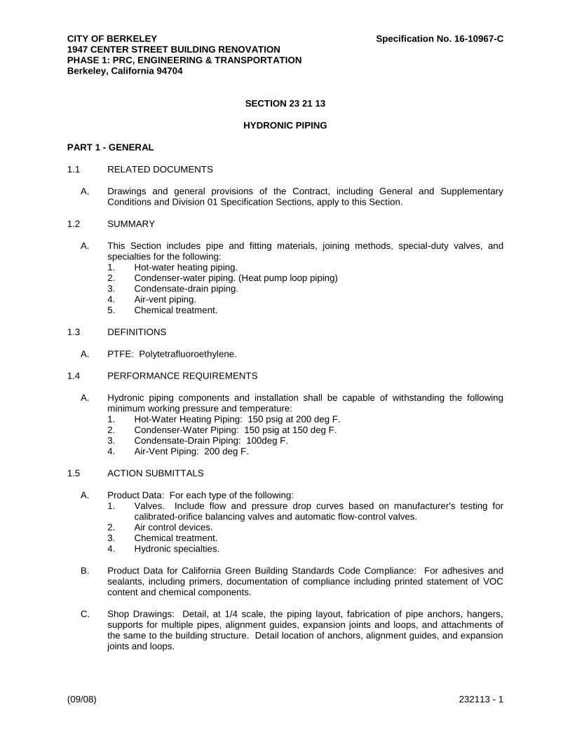
CITY OF BERKELEY Specification No. 16-10967-C 1947 CENTER STREET BUILDING RENOVATION PHASE 1: PRC, ENGINEERING & TRANSPORTATION Berkeley, California 94704
(09/08) 232113 - 1
SECTION 23 21 13
HYDRONIC PIPING
PART 1 - GENERAL
1.1 RELATED DOCUMENTS
A. Drawings and general provisions of the Contract, including General and Supplementary Conditions and Division 01 Specification Sections, apply to this Section.
1.2 SUMMARY
A. This Section includes pipe and fitting materials, joining methods, special-duty valves, and specialties for the following: 1. Hot-water heating piping. 2. Condenser-water piping. (Heat pump loop piping) 3. Condensate-drain piping. 4. Air-vent piping. 5. Chemical treatment.
1.3 DEFINITIONS
A. PTFE: Polytetrafluoroethylene.
1.4 PERFORMANCE REQUIREMENTS
A. Hydronic piping components and installation shall be capable of withstanding the following minimum working pressure and temperature: 1. Hot-Water Heating Piping: 150 psig at 200 deg F. 2. Condenser-Water Piping: 150 psig at 150 deg F. 3. Condensate-Drain Piping: 100deg F. 4. Air-Vent Piping: 200 deg F.
1.5 ACTION SUBMITTALS
A. Product Data: For each type of the following: 1. Valves. Include flow and pressure drop curves based on manufacturer's testing for
calibrated-orifice balancing valves and automatic flow-control valves. 2. Air control devices. 3. Chemical treatment. 4. Hydronic specialties.
B. Product Data for California Green Building Standards Code Compliance: For adhesives and sealants, including primers, documentation of compliance including printed statement of VOC content and chemical components.
C. Shop Drawings: Detail, at 1/4 scale, the piping layout, fabrication of pipe anchors, hangers, supports for multiple pipes, alignment guides, expansion joints and loops, and attachments of the same to the building structure. Detail location of anchors, alignment guides, and expansion joints and loops.
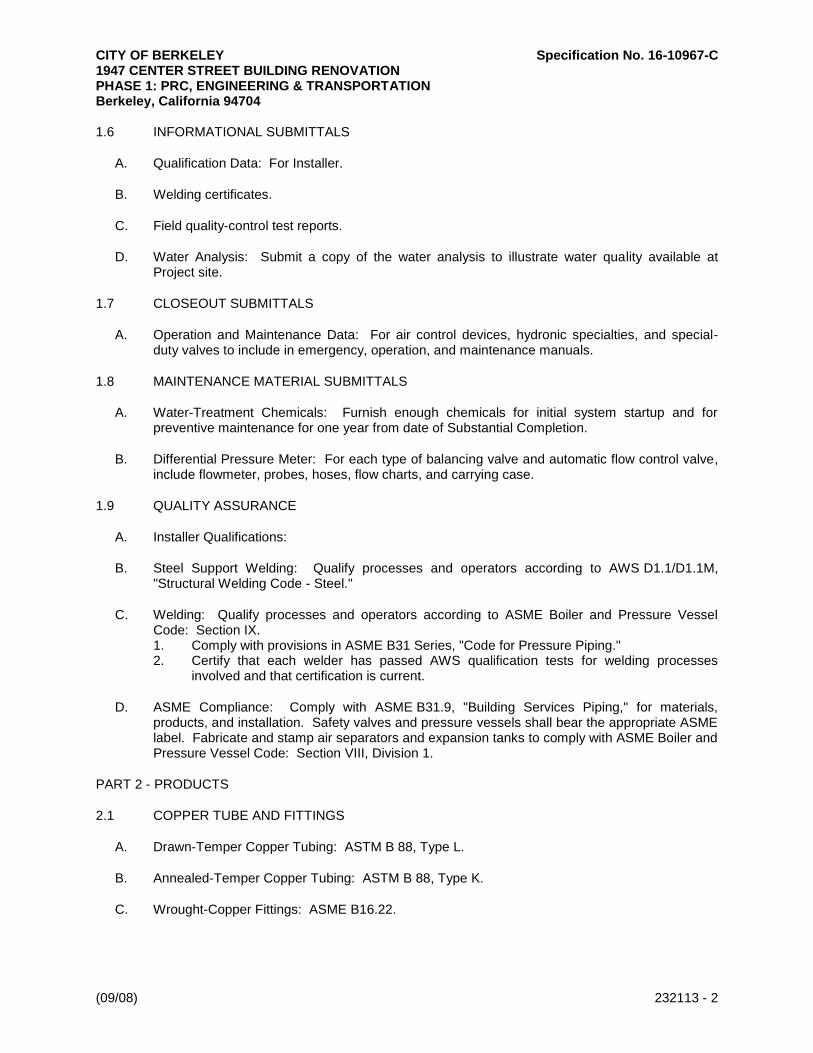
CITY OF BERKELEY Specification No. 16-10967-C 1947 CENTER STREET BUILDING RENOVATION PHASE 1: PRC, ENGINEERING & TRANSPORTATION Berkeley, California 94704
(09/08) 232113 - 2
1.6 INFORMATIONAL SUBMITTALS
A. Qualification Data: For Installer.
B. Welding certificates.
C. Field quality-control test reports.
D. Water Analysis: Submit a copy of the water analysis to illustrate water quality available at Project site.
1.7 CLOSEOUT SUBMITTALS
A. Operation and Maintenance Data: For air control devices, hydronic specialties, and special-duty valves to include in emergency, operation, and maintenance manuals.
1.8 MAINTENANCE MATERIAL SUBMITTALS
A. Water-Treatment Chemicals: Furnish enough chemicals for initial system startup and for preventive maintenance for one year from date of Substantial Completion.
B. Differential Pressure Meter: For each type of balancing valve and automatic flow control valve, include flowmeter, probes, hoses, flow charts, and carrying case.
1.9 QUALITY ASSURANCE
A. Installer Qualifications:
B. Steel Support Welding: Qualify processes and operators according to AWS D1.1/D1.1M, "Structural Welding Code - Steel."
C. Welding: Qualify processes and operators according to ASME Boiler and Pressure Vessel Code: Section IX. 1. Comply with provisions in ASME B31 Series, "Code for Pressure Piping." 2. Certify that each welder has passed AWS qualification tests for welding processes
involved and that certification is current.
D. ASME Compliance: Comply with ASME B31.9, "Building Services Piping," for materials, products, and installation. Safety valves and pressure vessels shall bear the appropriate ASME label. Fabricate and stamp air separators and expansion tanks to comply with ASME Boiler and Pressure Vessel Code: Section VIII, Division 1.
PART 2 - PRODUCTS
2.1 COPPER TUBE AND FITTINGS
A. Drawn-Temper Copper Tubing: ASTM B 88, Type L.
B. Annealed-Temper Copper Tubing: ASTM B 88, Type K.
C. Wrought-Copper Fittings: ASME B16.22.

CITY OF BERKELEY Specification No. 16-10967-C 1947 CENTER STREET BUILDING RENOVATION PHASE 1: PRC, ENGINEERING & TRANSPORTATION Berkeley, California 94704
(09/08) 232113 - 3
1. Available Manufacturers: Subject to compliance with requirements, manufacturers offering products that may be incorporated into the Work include, but are not limited to, the following: a. Anvil International, Inc. b. S. P. Fittings; a division of Star Pipe Products. c. Victaulic Company.
D. Wrought-Copper Unions: ASME B16.22.
2.2 STEEL PIPE AND FITTINGS
A. Steel Pipe: ASTM A 53/A 53M, black steel with plain ends; type, grade, and wall thickness as indicated in Part 3 "Piping Applications" Article.
B. Malleable-Iron Unions: ASME B16.39; Classes 150, 250, and 300 as indicated in Part 3 "Piping Applications" Article.
C. Cast-Iron Pipe Flanges and Flanged Fittings: ASME B16.1, Classes 25, 125, and 250; raised ground face, and bolt holes spot faced as indicated in Part 3 "Piping Applications" Article.
D. Steel Pipe Nipples: ASTM A 733, made of same materials and wall thicknesses as pipe in which they are installed.
2.3 JOINING MATERIALS
A. Pipe-Flange Gasket Materials: Suitable for chemical and thermal conditions of piping system contents. 1. ASME B16.21, nonmetallic, flat, asbestos free, 1/8-inch maximum thickness unless
thickness or specific material is indicated. a. Full-Face Type: For flat-face, Class 125, cast-iron and cast-bronze flanges. b. Narrow-Face Type: For raised-face, Class 250, cast-iron and steel flanges.
B. Flange Bolts and Nuts: ASME B18.2.1, carbon steel, unless otherwise indicated.
C. Solder Filler Metals: ASTM B 32, lead-free alloys. Include water-flushable flux according to ASTM B 813.
D. Brazing Filler Metals: AWS A5.8, BCuP Series, copper-phosphorus alloys for joining copper with copper; or BAg-1, silver alloy for joining copper with bronze or steel.
E. Welding Filler Metals: Comply with AWS D10.12/D10.12M for welding materials appropriate for wall thickness and chemical analysis of steel pipe being welded.
2.4 DIELECTRIC FITTINGS
A. General Requirements: Assembly of copper alloy and ferrous materials with separating nonconductive insulating material. Include end connections compatible with pipes to be joined.
B. Dielectric Unions: 1. Manufacturers: Subject to compliance with requirements, available manufacturers
offering products that may be incorporated into the Work include, but are not limited to, the following: a. Capitol Manufacturing Company.

CITY OF BERKELEY Specification No. 16-10967-C 1947 CENTER STREET BUILDING RENOVATION PHASE 1: PRC, ENGINEERING & TRANSPORTATION Berkeley, California 94704
(09/08) 232113 - 4
b. Central Plastics Company. c. Hart Industries International, Inc. d. Jomar International Ltd. e. Matco-Norca, Inc. f. McDonald, A. Y. Mfg. Co. g. Watts Regulator Co.; a division of Watts Water Technologies, Inc. h. Wilkins; a Zurn company.
2. Description: a. Standard: ASSE 1079. b. Pressure Rating: [150 psig]. c. End Connections: Solder-joint copper alloy and threaded ferrous.
2.5 VALVES
A. Comply with requirements specified in Section 23 05 23 "General-Duty Valves for HVAC Piping."
B. Automatic Temperature-Control Valves, Actuators, and Sensors: Comply with requirements specified in Section 23 09 00 "Instrumentation and Control for HVAC."
C. Bronze, Calibrated-Orifice, Balancing Valves: 1. Available Manufacturers: Subject to compliance with requirements, manufacturers
offering products that may be incorporated into the Work include, but are not limited to, the following: a. Armstrong Pumps, Inc. b. Bell & Gossett Domestic Pump; a division of ITT Industries. c. Flow Design Inc. d. Griswold Controls. e. Taco.
2. Body: Bronze, ball or plug type with calibrated orifice or venturi. 3. Ball: Brass or stainless steel. 4. Plug: Resin. 5. Seat: PTFE. 6. End Connections: Threaded or socket. 7. Pressure Gage Connections: Integral seals for portable differential pressure meter. 8. Handle Style: Lever, with memory stop to retain set position. 9. CWP Rating: Minimum 125 psig. 10. Maximum Operating Temperature: 250 deg F.
D. Automatic Flow-Control Valves: 1. Available Manufacturers: Subject to compliance with requirements, manufacturers
offering products that may be incorporated into the Work include, but are not limited to, the following: a. Flow Design Inc. b. Griswold Controls.
2. Body: Brass or ferrous metal. 3. Piston and Spring Assembly: [Stainless steel][Corrosion resistant], tamper proof, self
cleaning, and removable. 4. Combination Assemblies: Include bonze or brass-alloy ball valve. 5. Identification Tag: Marked with zone identification, valve number, and flow rate. 6. Size: Same as pipe in which installed. 7. Performance: Maintain constant flow, plus or minus 5 percent over system pressure
fluctuations. 8. Minimum CWP Rating: 175 psig.
CITY OF BERKELEY Specification No. 16-10967-C 1947 CENTER STREET BUILDING RENOVATION PHASE 1: PRC, ENGINEERING & TRANSPORTATION Berkeley, California 94704
(09/08) 232113 - 5
9. Maximum Operating Temperature.
2.6 AIR CONTROL DEVICES
A. Available Manufacturers: Subject to compliance with requirements, manufacturers offering products that may be incorporated into the Work include, but are not limited to, the following:
B. Manufacturers: Subject to compliance with requirements, provide products by one of the following: 1. Amtrol, Inc. 2. Armstrong Pumps, Inc. 3. Bell & Gossett Domestic Pump; a division of ITT Industries. 4. Taco.
C. Manual Air Vents: 1. Body: Bronze. 2. Internal Parts: Nonferrous. 3. Operator: Screwdriver or thumbscrew. 4. Inlet Connection: NPS 1/2. 5. Discharge Connection: NPS 1/8. 6. CWP Rating: 150 psig. 7. Maximum Operating Temperature: 225 deg F.
2.7 HYDRONIC PIPING SPECIALTIES
A. Y-Pattern Strainers: 1. Body: ASTM A 126, Class B, cast iron with bolted cover and bottom drain connection. 2. End Connections: Threaded ends for NPS 2 and smaller; flanged ends for NPS 2-1/2
and larger. 3. Strainer Screen: [40][60]-mesh startup strainer, and perforated stainless-steel basket
with 50 percent free area. 4. CWP Rating: 125 psig.
B. Stainless Steel Corrugated; Flexible Connectors: 1. Inner Corrugated Hose: Type 304 stainless steel. 2. Outer Braid: Type 304 stainless steel. 3. End Fittings: To suit installation. 4. Performance: Capable of misalignment. 5. CWP Rating: 150 psig. 6. Maximum Operating Temperature: 250 deg F.
PART 3 - EXECUTION
3.1 PIPING APPLICATIONS
A. Hot-water heating piping, aboveground, NPS 2 and smaller, shall be any of the following: 1. Type L, drawn-temper copper tubing, wrought-copper fittings, and brazed joints. 2. Schedule 40 steel pipe; Class 150, malleable-iron fittings; cast-iron flanges and flange
fittings; and threaded joints.
B. Condenser-water piping (heat pump loop water), aboveground, NPS 2 and smaller, shall be any of the following: 1. Type L, drawn-temper copper tubing, wrought-copper fittings, and brazed joints.
CITY OF BERKELEY Specification No. 16-10967-C 1947 CENTER STREET BUILDING RENOVATION PHASE 1: PRC, ENGINEERING & TRANSPORTATION Berkeley, California 94704
(09/08) 232113 - 6
2. Schedule 40 steel pipe; Class 150, malleable-iron fittings; cast-iron flanges and flange fittings; and threaded joints.
C. Condensate Drain Piping: 1. General Use: Type L, drawn-temper copper tubing, wrought-copper fittings, and soldered
joints.
D. Air-Vent Piping: 1. Inlet: Same as service where installed with metal-to-plastic transition fittings for plastic
piping systems according to the piping manufacturer's written instructions. 2. Outlet: Type K, annealed-temper copper tubing with soldered or flared joints.
3.2 VALVE APPLICATIONS
A. Install shutoff-duty valves at each branch connection to supply mains, and at supply connection to each piece of equipment.
B. Install calibrated-orifice, balancing valves at each branch connection to return main.
C. Install calibrated-orifice, balancing valves in the return pipe of each heating or cooling terminal.
D. Install check valves at each pump discharge and elsewhere as required to control flow direction.
E. Install safety valves at hot-water generators and elsewhere as required by ASME Boiler and Pressure Vessel Code. Install drip-pan elbow on safety-valve outlet and pipe without valves to the outdoors; and pipe drain to nearest floor drain or as indicated on Drawings. Comply with ASME Boiler and Pressure Vessel Code: Section VIII, Division 1, for installation requirements.
F. Install pressure-reducing valves at makeup-water connection to regulate system fill pressure.
3.3 PIPING INSTALLATIONS
A. Drawing plans, schematics, and diagrams indicate general location and arrangement of piping systems. Indicate piping locations and arrangements if such were used to size pipe and calculate friction loss, expansion, pump sizing, and other design considerations. Install piping as indicated unless deviations to layout are approved on Coordination Drawings.
B. Install piping in concealed locations, unless otherwise indicated and except in equipment rooms and service areas.
C. Install piping indicated to be exposed and piping in equipment rooms and service areas at right angles or parallel to building walls. Diagonal runs are prohibited unless specifically indicated otherwise.
D. Install piping above accessible ceilings to allow sufficient space for ceiling panel removal.
E. Install piping to permit valve servicing.
F. Install piping at indicated slopes.
G. Install piping free of sags and bends.
H. Install fittings for changes in direction and branch connections.

CITY OF BERKELEY Specification No. 16-10967-C 1947 CENTER STREET BUILDING RENOVATION PHASE 1: PRC, ENGINEERING & TRANSPORTATION Berkeley, California 94704
(09/08) 232113 - 7
I. Install piping to allow application of insulation.
J. Select system components with pressure rating equal to or greater than system operating pressure.
K. Install groups of pipes parallel to each other, spaced to permit applying insulation and servicing of valves.
L. Install drains, consisting of a tee fitting, NPS 3/4 ball valve, and short NPS 3/4 threaded nipple with cap, at low points in piping system mains and elsewhere as required for system drainage.
M. Install piping at a uniform grade of 0.2 percent upward in direction of flow.
N. Reduce pipe sizes using eccentric reducer fitting installed with level side up.
O. Install branch connections to mains using tee fittings in main pipe, with the branch connected to the bottom of the main pipe. For up-feed risers, connect the branch to the top of the main pipe.
P. Install valves according to Section 23 05 23 "General-Duty Valves for HVAC Piping."
Q. Install unions in piping, NPS 2 and smaller, adjacent to valves, at final connections of equipment, and elsewhere as indicated.
R. Install strainers on inlet side of each control valve, pressure-reducing valve, solenoid valve, in-line pump, and elsewhere as indicated. Install NPS 3/4 nipple and ball valve in blowdown connection of strainers NPS 2 and larger. Match size of strainer blowoff connection for strainers smaller than NPS 2.
S. Identify piping as specified in Section 23 05 53 "Identification for HVAC Piping and Equipment."
T. Install sleeves for piping penetrations of walls, ceilings, and floors. Comply with requirements for sleeves specified in Section 23 05 17 "Sleeves and Sleeve Seals for HVAC Piping."
U. Install sleeve seals for piping penetrations of concrete walls and slabs. Comply with requirements for sleeve seals specified in Section 23 05 17 "Sleeves and Sleeve Seals for HVAC Piping."
V. Install escutcheons for piping penetrations of walls, ceilings, and floors. Comply with requirements for escutcheons specified in Section 23 05 18 "Escutcheons for HVAC Piping."
3.4 HANGERS AND SUPPORTS
A. Hanger, support, and anchor devices are specified in Section 23 05 29 "Hangers and Supports for HVAC Piping and Equipment." Comply with the following requirements for maximum spacing of supports.
B. Seismic restraints are specified in Section 23 05 48 "Vibration and Seismic Controls for HVAC Piping and Equipment."
C. Install the following pipe attachments: 1. Adjustable steel clevis hangers for individual horizontal piping less than 20 feet long. 2. Adjustable roller hangers and spring hangers for individual horizontal piping 20 feet or
longer.

CITY OF BERKELEY Specification No. 16-10967-C 1947 CENTER STREET BUILDING RENOVATION PHASE 1: PRC, ENGINEERING & TRANSPORTATION Berkeley, California 94704
(09/08) 232113 - 8
3. Spring hangers to support vertical runs. 4. Provide copper-clad hangers and supports for hangers and supports in direct contact with
copper pipe.
D. Install hangers for steel piping with the following maximum spacing and minimum rod sizes: 1. NPS 3/4: Maximum span, 7 feet; minimum rod size, 1/4 inch. 2. NPS 1: Maximum span, 7 feet; minimum rod size, 1/4 inch. 3. NPS 1-1/2: Maximum span, 9 feet; minimum rod size, 3/8 inch. 4. NPS 2: Maximum span, 10 feet; minimum rod size, 3/8 inch. 5. NPS 2-1/2: Maximum span, 11 feet; minimum rod size, 3/8 inch. 6. NPS 3: Maximum span, 12 feet; minimum rod size, 3/8 inch. 7. NPS 4: Maximum span, 14 feet; minimum rod size, 1/2 inch.
E. Install hangers for drawn-temper copper piping with the following maximum spacing and minimum rod sizes: 1. NPS 3/4: Maximum span, 5 feet; minimum rod size, 1/4 inch. 2. NPS 1: Maximum span, 6 feet; minimum rod size, 1/4 inch. 3. NPS 1-1/2: Maximum span, 8 feet; minimum rod size, 3/8 inch. 4. NPS 2: Maximum span, 8 feet; minimum rod size, 3/8 inch. 5. NPS 2-1/2: Maximum span, 9 feet; minimum rod size, 3/8 inch. 6. NPS 3: Maximum span, 10 feet; minimum rod size, 3/8 inch.
3.5 PIPE JOINT CONSTRUCTION
A. Ream ends of pipes and tubes and remove burrs. Bevel plain ends of steel pipe.
B. Remove scale, slag, dirt, and debris from inside and outside of pipe and fittings before assembly.
C. Soldered Joints: Apply ASTM B 813, water-flushable flux, unless otherwise indicated, to tube end. Construct joints according to ASTM B 828 or CDA's "Copper Tube Handbook," using lead-free solder alloy complying with ASTM B 32.
D. Brazed Joints: Construct joints according to AWS's "Brazing Handbook," "Pipe and Tube" Chapter, using copper-phosphorus brazing filler metal complying with AWS A5.8.
3.6 HYDRONIC SPECIALTIES INSTALLATION
A. Install manual air vents at high points in piping, at heat-transfer coils, and elsewhere as required for system air venting.
B. Install flexible connections and calibrated valves at the locations noted on the plan details.
3.7 FIELD QUALITY CONTROL
A. Prepare hydronic piping according to ASME B31.9 and as follows: 1. Leave joints, including welds, uninsulated and exposed for examination during test. 2. Provide temporary restraints for expansion joints that cannot sustain reactions due to test
pressure. If temporary restraints are impractical, isolate expansion joints from testing. 3. Flush hydronic piping systems with clean water; then remove and clean or replace
strainer screens. 4. Isolate equipment from piping. If a valve is used to isolate equipment, its closure shall be
capable of sealing against test pressure without damage to valve. Install blinds in flanged joints to isolate equipment.
CITY OF BERKELEY Specification No. 16-10967-C 1947 CENTER STREET BUILDING RENOVATION PHASE 1: PRC, ENGINEERING & TRANSPORTATION Berkeley, California 94704
(09/08) 232113 - 9
5. Install safety valve, set at a pressure no more than one-third higher than test pressure, to protect against damage by expanding liquid or other source of overpressure during test.
B. Perform the following tests on hydronic piping: 1. Use ambient temperature water as a testing medium unless there is risk of damage due
to freezing. Another liquid that is safe for workers and compatible with piping may be used.
2. While filling system, use vents installed at high points of system to release air. Use drains installed at low points for complete draining of test liquid.
3. Isolate expansion tanks and determine that hydronic system is full of water. 4. Subject piping system to hydrostatic test pressure that is not less than 1.5 times the
system's working pressure. Test pressure shall not exceed maximum pressure for any vessel, pump, valve, or other component in system under test. Verify that stress due to pressure at bottom of vertical runs does not exceed 90 percent of specified minimum yield strength or 1.7 times "SE" value in Appendix A in ASME B31.9, "Building Services Piping."
5. After hydrostatic test pressure has been applied for at least four hours, examine piping, joints, and connections for leakage. Eliminate leaks by tightening, repairing, or replacing components, and repeat hydrostatic test until there are no leaks.
6. Prepare written report of testing.
C. Perform the following before operating the system: 1. Open manual valves fully. 2. Inspect pumps for proper rotation. 3. Set makeup pressure-reducing valves for required system pressure. 4. Inspect air vents at high points of system and determine if all are installed and operating
freely (automatic type), or bleed air completely (manual type). 5. Set temperature controls so all coils are calling for full flow. 6. Inspect and set operating temperatures of hydronic equipment, such as boilers, chillers,
cooling towers, to specified values. 7. Verify lubrication of motors and bearings.
D. New sections of piping shall be chemically treated to maintain a proper water balance for the use and materials incorporated within the system. Confirm with Owner, what chemicals are in use in the closed loop system and consult with water treatment professional to include the correct chemical balance for the new and enlarge system.
END OF SECTION

CITY OF BERKELEY Specification No. 16-10967-C 1947 CENTER STREET BUILDING RENOVATION PHASE 1: PRC, ENGINEERING & TRANSPORTATION Berkeley, California 94704
(09/08) 232116 - 1
SECTION 23 21 16
HYDRONIC PIPING SPECIALTIES
PART 1 - GENERAL
1.1 RELATED DOCUMENTS
A. Drawings and general provisions of the Contract, including General and Supplementary Conditions and Division 01 Specification Sections, apply to this Section.
1.2 SUMMARY
A. Section includes special-duty valves and specialties for the following: 1. Hot-water heating piping. 2. Condenser-water piping. 3. Condensate-drain piping.
1.3 ACTION SUBMITTALS
A. Product Data: For each type of the following: 1. Valves: Include flow and pressure drop curves based on manufacturer's testing for
calibrated-orifice balancing valves and automatic flow-control valves. 2. Air-control devices. 3. Hydronic specialties.
1.4 CLOSEOUT SUBMITTALS
A. Operation and Maintenance Data: For air-control devices, hydronic specialties, and special-duty valves to include in emergency, operation, and maintenance manuals.
1.5 MAINTENANCE MATERIAL SUBMITTALS
A. Differential Pressure Meter: For each type of balancing valve and automatic flow control valve, include flowmeter, probes, hoses, flow charts, and carrying case.
1.6 QUALITY ASSURANCE
A. Pipe Welding: Qualify procedures and operators according to ASME Boiler and Pressure Vessel Code: Section IX. 1. Safety valves and pressure vessels shall bear the appropriate ASME label. Fabricate and
stamp air separators and expansion tanks to comply with ASME Boiler and Pressure Vessel Code: Section VIII, Division 1.
PART 2 - PRODUCTS
2.1 PERFORMANCE REQUIREMENTS
A. Hydronic piping components and installation shall be capable of withstanding the following minimum working pressure and temperature unless otherwise indicated: 1. Hot-Water Heating Piping: <100 psig at 200 deg F . 2. Condenser-Water Piping: <100 psig at [100 deg F .

CITY OF BERKELEY Specification No. 16-10967-C 1947 CENTER STREET BUILDING RENOVATION PHASE 1: PRC, ENGINEERING & TRANSPORTATION Berkeley, California 94704
(09/08) 232116 - 2
3. Condensate-Drain Piping: 50 deg F . 4. .
2.2 VALVES
A. Gate, Globe, Check, Ball, and Butterfly Valves: Comply with requirements specified in Section 23 05 23 "General-Duty Valves for HVAC Piping."
B. Automatic Temperature-Control Valves, Actuators, and Sensors: Comply with requirements specified in Section 23 09 23.11 "Control Valves."Section 15901 "Control Valves." 1. Manufacturers: Subject to compliance with requirements, available manufacturers
offering products that may be incorporated into the Work include, but are not limited to the following: a. American Valve, Inc. b. Asahi/America. c. Charlotte Pipe and Foundry Company. d. Colonial Engineering, Inc. e. Georg Fischer Inc. f. Hayward Flow Control; a division of Hayward Industries, Inc. g. IPEX USA LLC. h. Jomar Valve. i. KBI (King Bros. Industries). j. Legend Valve. k. NIBCO INC. l. Plast-O-Matic Valves, Inc. m. SMC The Specialty Mfg. Co. n. Thermoplastic Valves, Inc.
2. Body: One-, two-, or three-piece CPVC or PVC to match piping. 3. Ball: Full-port CPVC or PVC to match piping. 4. Seats: PTFE. 5. Seals: EPDM. 6. End Connections: Socket, union, or flanged. 7. Handle Style: Tee shape. 8. CWP Rating: Equal to piping service. 9. Maximum Operating Temperature: Equal to piping service. 10. Comply with MSS SP-122.
C. Plastic Butterfly Valves: 1. Manufacturers: Subject to compliance with requirements, available manufacturers
offering products that may be incorporated into the Work include, but are not limited to the following: a. American Valve, Inc. b. Asahi/America. c. Colonial Engineering, Inc. d. Georg Fischer Inc. e. Hayward Flow Control; a division of Hayward Industries, Inc. f. IPEX USA LLC. g. Legend Valve. h. NIBCO INC. i. Plast-O-Matic Valves, Inc. j. SMC The Specialty Mfg. Co. k. Thermoplastic Valves, Inc. l. Watts; a Watts Water Technologies company.
2. Body: PVC or CPVC to match piping wafer type for installation between flanges.

CITY OF BERKELEY Specification No. 16-10967-C 1947 CENTER STREET BUILDING RENOVATION PHASE 1: PRC, ENGINEERING & TRANSPORTATION Berkeley, California 94704
(09/08) 232116 - 3
3. Disc: EPDM-coated steel. 4. Seats: PTFE. 5. Handle Style: Locking lever. 6. CWP Rating: Equal to piping service. 7. Maximum Operating Temperature: Equal to piping service.
D. Plastic Check Valves: 1. Manufacturers: Subject to compliance with requirements, available manufacturers
offering products that may be incorporated into the Work include, but are not limited to the following: a. American Valve, Inc. b. Asahi/America. c. Colonial Engineering, Inc. d. Georg Fischer Inc. e. Hayward Flow Control; a division of Hayward Industries, Inc. f. IPEX USA LLC. g. KBI (King Bros. Industries). h. Legend Valve. i. NIBCO INC. j. Plast-O-Matic Valves, Inc. k. SMC The Specialty Mfg. Co. l. Thermoplastic Valves, Inc. m. Watts; a Watts Water Technologies company.
2. Body: One-, two-, or three-piece PVC or CPVC to match piping. 3. Ends: Socket or flanged. 4. Seats: PTFE. 5. Check Style: Swing or ball type. 6. CWP Rating: Equal to piping service. 7. Maximum Operating Temperature: Equal to piping service.
E. Bronze, Calibrated-Orifice, Balancing Valves: 1. Manufacturers: Subject to compliance with requirements, available manufacturers
offering products that may be incorporated into the Work include, but are not limited to the following: a. Armstrong Pumps, Inc. b. Bell & Gossett; a Xylem brand. c. Flow Design, Inc. d. Gerand Engineering Co. e. Griswold Controls. f. HCI; Hydronics Components Inc. g. Nexus Valve, Inc. h. NuTech Hydronic Specialty Products. i. Oventrop Corporation. j. Taco. k. Tour & Andersson; available through Victaulic Company. l. Tunstall Corporation. m. Victaulic Company.
2. Body: Bronze, ball or plug type with calibrated orifice or venturi. 3. Ball: Brass or stainless steel. 4. Plug: Resin. 5. Seat: PTFE. 6. End Connections: Threaded or socket. 7. Pressure Gage Connections: Integral seals for portable differential pressure meter. 8. Handle Style: Lever, with memory stop to retain set position.

CITY OF BERKELEY Specification No. 16-10967-C 1947 CENTER STREET BUILDING RENOVATION PHASE 1: PRC, ENGINEERING & TRANSPORTATION Berkeley, California 94704
(09/08) 232116 - 4
9. CWP Rating: Minimum 125 psig (860 kPa). 10. Maximum Operating Temperature: 250 deg F (121 deg C).
F. Cast-Iron or Steel, Calibrated-Orifice, Balancing Valves: 1. Manufacturers: Subject to compliance with requirements, available manufacturers
offering products that may be incorporated into the Work include, but are not limited to the following: a. Armstrong Pumps, Inc. b. Bell & Gossett; a Xylem brand. c. Flow Design, Inc. d. Gerand Engineering Co. e. Griswold Controls. f. HCI; Hydronics Components Inc. g. Nexus Valve, Inc. h. NuTech Hydronic Specialty Products. i. Oventrop Corporation. j. Taco. k. Tour & Andersson; available through Victaulic Company. l. Tunstall Corporation. m. Victaulic Company.
2. Body: Cast-iron or steel body, ball, plug, or globe pattern with calibrated orifice or venturi. 3. Ball: Brass or stainless steel. 4. Stem Seals: EPDM O-rings. 5. Disc: Glass and carbon-filled PTFE. 6. Seat: PTFE. 7. End Connections: Flanged or grooved. 8. Pressure Gage Connections: Integral seals for portable differential pressure meter. 9. Handle Style: Lever, with memory stop to retain set position. 10. CWP Rating: Minimum 125 psig (860 kPa). 11. Maximum Operating Temperature: 250 deg F (121 deg C).
G. Automatic Flow-Control Valves: 1. Manufacturers: Subject to compliance with requirements, available manufacturers
offering products that may be incorporated into the Work include, but are not limited to the following: a. Flow Design, Inc. b. Flowcon Americas LLC. c. Griswold Controls. d. HCI; Hydronics Components Inc. e. Nexus Valve, Inc. f. NuTech Hydronic Specialty Products. g. Tunstall Corporation.
2. Body: Brass or ferrous metal. 3. Piston and Spring Assembly: [Stainless steel] [Corrosion resistant], tamper proof, self-
cleaning, and removable. 4. Combination Assemblies: Include bronze or brass-alloy ball valve. 5. Identification Tag: Marked with zone identification, valve number, and flow rate. 6. Size: Same as pipe in which installed. 7. Performance: Maintain constant flow, plus or minus 5 percent over system pressure
fluctuations. 8. Minimum CWP Rating: [175 psig (1207 kPa)] [300 psig (2070 kPa)]. 9. Maximum Operating Temperature: [200 deg F (93 deg C)] [250 deg F (121 deg C)].

CITY OF BERKELEY Specification No. 16-10967-C 1947 CENTER STREET BUILDING RENOVATION PHASE 1: PRC, ENGINEERING & TRANSPORTATION Berkeley, California 94704
(09/08) 232116 - 5
2.3 AIR-CONTROL DEVICES
A. Manual Air Vents: 1. Manufacturers: Subject to compliance with requirements, available manufacturers
offering products that may be incorporated into the Work include, but are not limited to the following: a. AMTROL, Inc. b. Armstrong Pumps, Inc. c. Bell & Gossett; a Xylem brand. d. Nexus Valve, Inc. e. NuTech Hydronic Specialty Products. f. Taco, Inc.
2. Body: Bronze. 3. Internal Parts: Nonferrous. 4. Operator: Screwdriver or thumbscrew. 5. Inlet Connection: NPS 1/2 (DN 15). 6. Discharge Connection: NPS 1/8 (DN 6). 7. CWP Rating: 150 psig (1035 kPa). 8. Maximum Operating Temperature: 225 deg F (107 deg C).
2.4 HYDRONIC PIPING SPECIALTIES
A. Y-Pattern Strainers: 1. Body: ASTM A 126, Class B, cast iron with bolted cover and bottom drain connection. 2. End Connections: Threaded ends for NPS 2 (DN 50) and smaller; flanged ends for
NPS 2-1/2 (DN 65) and larger. 3. Strainer Screen: Stainless-steel, [20] [40] [60]-mesh strainer, or perforated stainless-steel
basket. 4. CWP Rating: 125 psig (860 kPa).
PART 3 - EXECUTION
3.1 VALVE APPLICATIONS
A. Install shutoff-duty valves at each branch connection to supply mains and at supply connection to each piece of equipment.
B. Install calibrated-orifice, balancing valves at each branch connection to return main.
C. Install calibrated-orifice, balancing valves in the return pipe of each heating or cooling terminal.
D. Install check valves at each pump discharge and elsewhere as required to control flow direction.
E. Install safety valves at hot-water generators and elsewhere as required by ASME Boiler and Pressure Vessel Code. Install drip-pan elbow on safety-valve outlet and pipe without valves to the outdoors; pipe drain to nearest floor drain or as indicated on Drawings. Comply with ASME Boiler and Pressure Vessel Code: Section VIII, Division 1, for installation requirements.
F. Install pressure-reducing valves at makeup-water connection to regulate system fill pressure.
3.2 HYDRONIC SPECIALTIES INSTALLATION
A. Install manual air vents at high points in piping, at heat-transfer coils, and elsewhere as required for system air venting.

CITY OF BERKELEY Specification No. 16-10967-C 1947 CENTER STREET BUILDING RENOVATION PHASE 1: PRC, ENGINEERING & TRANSPORTATION Berkeley, California 94704
(09/08) 232116 - 6
END OF SECTION

CITY OF BERKELEY Specification No. 16-10967-C 1947 CENTER STREET BUILDING RENOVATION PHASE 1: PRC, ENGINEERING & TRANSPORTATION Berkeley, California 94704
(09/08) 233113 - 1
SECTION 23 31 13
METAL DUCTS
PART 1 - GENERAL
1.1 RELATED DOCUMENTS
A. Drawings and general provisions of the Contract, including General and Supplementary Conditions and Division 01 Specification Sections, apply to this Section.
1.2 SUMMARY
A. Section Includes: 1. Single-wall rectangular ducts and fittings. 2. Single-wall round and flat-oval ducts and fittings. 3. Sheet metal materials. 4. Duct liner. 5. Sealants and gaskets. 6. Hangers and supports. 7. Seismic-restraint devices.
B. Related Sections: 1. Section 23 05 93 "Testing, Adjusting, and Balancing for HVAC" for testing, adjusting, and
balancing requirements for metal ducts. 2. Section 23 33 00 "Air Duct Accessories" for dampers, sound-control devices, duct-
mounting access doors and panels, turning vanes, and flexible ducts.
1.3 PERFORMANCE REQUIREMENTS
A. Delegated Duct Design: Duct construction, including sheet metal thicknesses, seam and joint construction, reinforcements, and hangers and supports, shall comply with SMACNA's "HVAC Duct Construction Standards - Metal and Flexible" and performance requirements and design criteria indicated in "Duct Schedule" Article.
B. Structural Performance: Duct hangers and supports and seismic restraints shall withstand the effects of gravity and seismic loads and stresses within limits and under conditions described in SMACNA's "HVAC Duct Construction Standards - Metal and Flexible" and SMACNA's "Seismic Restraint Manual: Guidelines for Mechanical Systems" or other standards as required by the AHJ. 1. Seismic Hazard Level A: Seismic force to weight ratio, 0.48.
1.4 ACTION SUBMITTALS
A. Product Data: For each type of the following products: 1. Liners and adhesives. 2. Sealants and gaskets. 3. Seismic-restraint devices.
B. Shop Drawings: 1. Fabrication, assembly, and installation, including plans, elevations, sections,
components, and attachments to other work. 2. Factory- and shop-fabricated ducts and fittings.

CITY OF BERKELEY Specification No. 16-10967-C 1947 CENTER STREET BUILDING RENOVATION PHASE 1: PRC, ENGINEERING & TRANSPORTATION Berkeley, California 94704
(09/08) 233113 - 2
3. Duct layout indicating sizes, configuration, liner material, and static-pressure classes. 4. Elevation of top of ducts. 5. Dimensions of main duct runs from building grid lines. 6. Fittings. 7. Reinforcement and spacing. 8. Seam and joint construction. 9. Penetrations through fire-rated and other partitions. 10. Equipment installation based on equipment being used on Project. 11. Locations for duct accessories, including dampers, turning vanes, and access doors and
panels. 12. Hangers and supports, including methods for duct and building attachment, seismic
restraints, and vibration isolation.
C. Delegated-Design Submittal: 1. Sheet metal thicknesses. 2. Joint and seam construction and sealing. 3. Reinforcement details and spacing. 4. Materials, fabrication, assembly, and spacing of hangers and supports. 5. Design Calculations: Calculations[, including analysis data signed and sealed by the
qualified professional engineer responsible for their preparation] for selecting hangers and supports and seismic restraints.
1.5 INFORMATIONAL SUBMITTALS
A. Coordination Drawings: Plans, drawn to scale, on which the following items are shown and coordinated with each other, using input from installers of the items involved: 1. Duct installation in congested spaces, indicating coordination with general construction,
building components, and other building services. Indicate proposed changes to duct layout.
2. Suspended ceiling components. 3. Structural members to which duct will be attached. 4. Size and location of initial access modules for acoustical tile. 5. Penetrations of smoke barriers and fire-rated construction. 6. Items penetrating finished ceiling including the following:
a. Lighting fixtures. b. Air outlets and inlets. c. Speakers. d. Sprinklers. e. Access panels. f. Perimeter moldings.
B. Field quality-control reports.
1.6 QUALITY ASSURANCE
A. Welding Qualifications: Qualify procedures and personnel according to the following: 1. AWS D1.1/D1.1M, "Structural Welding Code - Steel," for hangers and supports. 2. AWS D9.1M/D9.1, "Sheet Metal Welding Code," for duct joint and seam welding.

CITY OF BERKELEY Specification No. 16-10967-C 1947 CENTER STREET BUILDING RENOVATION PHASE 1: PRC, ENGINEERING & TRANSPORTATION Berkeley, California 94704
(09/08) 233113 - 3
PART 2 - PRODUCTS
2.1 SINGLE-WALL RECTANGULAR DUCTS AND FITTINGS
A. General Fabrication Requirements: Comply with SMACNA's "HVAC Duct Construction Standards - Metal and Flexible" based on indicated static-pressure class unless otherwise indicated.
B. Transverse Joints: Select joint types and fabricate according to SMACNA's "HVAC Duct Construction Standards - Metal and Flexible," Figure 2-1, "Rectangular Duct/Transverse Joints," for static-pressure class, applicable sealing requirements, materials involved, duct-support intervals, and other provisions in SMACNA's "HVAC Duct Construction Standards - Metal and Flexible."
C. Longitudinal Seams: Select seam types and fabricate according to SMACNA's "HVAC Duct Construction Standards - Metal and Flexible," Figure 2-2, "Rectangular Duct/Longitudinal Seams," for static-pressure class, applicable sealing requirements, materials involved, duct-support intervals, and other provisions in SMACNA's "HVAC Duct Construction Standards - Metal and Flexible."
D. Elbows, Transitions, Offsets, Branch Connections, and Other Duct Construction: Select types and fabricate according to SMACNA's "HVAC Duct Construction Standards - Metal and Flexible," Chapter 4, "Fittings and Other Construction," for static-pressure class, applicable sealing requirements, materials involved, duct-support intervals, and other provisions in SMACNA's "HVAC Duct Construction Standards - Metal and Flexible."
2.2 SINGLE-WALL ROUND AND FLAT-OVAL DUCTS AND FITTINGS
A. General Fabrication Requirements: Comply with SMACNA's "HVAC Duct Construction Standards - Metal and Flexible," Chapter 3, "Round, Oval, and Flexible Duct," based on indicated static-pressure class unless otherwise indicated. 1. Manufacturers: Subject to compliance with requirements, available manufacturers
offering products that may be incorporated into the Work include, but are not limited to, the following: a. Lindab Inc. b. McGill AirFlow LLC. c. SEMCO Incorporated. d. Sheet Metal Connectors, Inc. e. Spiral Manufacturing Co., Inc.
B. Flat-Oval Ducts: Indicated dimensions are the duct width (major dimension) and diameter of the round sides connecting the flat portions of the duct (minor dimension).
C. Transverse Joints: Select joint types and fabricate according to SMACNA's "HVAC Duct Construction Standards - Metal and Flexible," Figure 3-1, "Round Duct Transverse Joints," for static-pressure class, applicable sealing requirements, materials involved, duct-support intervals, and other provisions in SMACNA's "HVAC Duct Construction Standards - Metal and Flexible." 1. Transverse Joints in Ducts Larger Than in Diameter: Flanged.
D. Longitudinal Seams: Select seam types and fabricate according to SMACNA's "HVAC Duct Construction Standards - Metal and Flexible," Figure 3-2, "Round Duct Longitudinal Seams," for static-pressure class, applicable sealing requirements, materials involved, duct-support

CITY OF BERKELEY Specification No. 16-10967-C 1947 CENTER STREET BUILDING RENOVATION PHASE 1: PRC, ENGINEERING & TRANSPORTATION Berkeley, California 94704
(09/08) 233113 - 4
intervals, and other provisions in SMACNA's "HVAC Duct Construction Standards - Metal and Flexible." 1. Fabricate round ducts larger than 90 inches in diameter with butt-welded longitudinal
seams. 2. Fabricate flat-oval ducts larger than 72 inches in width (major dimension) with butt-
welded longitudinal seams.
E. Tees and Laterals: Select types and fabricate according to SMACNA's "HVAC Duct Construction Standards - Metal and Flexible," Figure 3-5, "90 Degree Tees and Laterals," and Figure 3-6, "Conical Tees," for static-pressure class, applicable sealing requirements, materials involved, duct-support intervals, and other provisions in SMACNA's "HVAC Duct Construction Standards - Metal and Flexible."
2.3 SHEET METAL MATERIALS
A. General Material Requirements: Comply with SMACNA's "HVAC Duct Construction Standards - Metal and Flexible" for acceptable materials, material thicknesses, and duct construction methods unless otherwise indicated. Sheet metal materials shall be free of pitting, seam marks, roller marks, stains, discolorations, and other imperfections.
B. Galvanized Sheet Steel: Comply with ASTM A 653/A 653M. 1. Galvanized Coating Designation: G90. 2. Finishes for Surfaces Exposed to View: Mill phosphatized.
C. Carbon-Steel Sheets: Comply with ASTM A 1008/A 1008M, with oiled, matte finish for exposed ducts.
D. Stainless-Steel Sheets: Comply with ASTM A 480/A 480M, Type 304 or 316, as indicated in the "Duct Schedule" Article; cold rolled, annealed, sheet. Exposed surface finish shall be No. 2B, No. 2D, No. 3, or No. 4 as indicated in the "Duct Schedule" Article.
E. Aluminum Sheets: Comply with ASTM B 209 Alloy 3003, H14 temper; with mill finish for concealed ducts, and standard, one-side bright finish for duct surfaces exposed to view.
F. Factory- or Shop-Applied Antimicrobial Coating: 1. Apply to the surface of sheet metal that will form the interior surface of the duct. An
untreated clear coating shall be applied to the exterior surface. 2. Antimicrobial compound shall be tested for efficacy by an NRTL and registered by the
EPA for use in HVAC systems. 3. Coating containing the antimicrobial compound shall have a hardness of 2H, minimum,
when tested according to ASTM D 3363. 4. Surface-Burning Characteristics: Maximum flame-spread index of 25 and maximum
smoke-developed index of 50 when tested according to UL 723; certified by an NRTL. 5. Shop-Applied Coating Color: [Black][White]. 6. Antimicrobial coating on sheet metal is not required for duct containing liner treated with
antimicrobial coating.
G. Reinforcement Shapes and Plates: ASTM A 36/A 36M, steel plates, shapes, and bars; black and galvanized. 1. Where black- and galvanized-steel shapes and plates are used to reinforce aluminum
ducts, isolate the different metals with butyl rubber, neoprene, or EPDM gasket materials.
H. Tie Rods: Galvanized steel, 1/4-inch minimum diameter for lengths 36 inches or less; 3/8-inch minimum diameter for lengths longer than 36 inches.
CITY OF BERKELEY Specification No. 16-10967-C 1947 CENTER STREET BUILDING RENOVATION PHASE 1: PRC, ENGINEERING & TRANSPORTATION Berkeley, California 94704
(09/08) 233113 - 5
2.4 DUCT LINER
A. Fibrous-Glass Duct Liner: Comply with ASTM C 1071, NFPA 90A, or NFPA 90B; and with NAIMA AH124, "Fibrous Glass Duct Liner Standard." 1. Manufacturers: Subject to compliance with requirements, available manufacturers
offering products that may be incorporated into the Work include, but are not limited to, the following: a. CertainTeed Corporation; Insulation Group. b. Johns Manville. c. Knauf Insulation. d. Owens Corning. e. Maximum Thermal Conductivity:
1) Type I, Flexible: 0.27 Btu x in./h x sq. ft. x deg F at 75 deg F mean temperature.
2. Antimicrobial Erosion-Resistant Coating: Apply to the surface of the liner that will form the interior surface of the duct to act as a moisture repellent and erosion-resistant coating. Antimicrobial compound shall be tested for efficacy by an NRTL and registered by the EPA for use in HVAC systems.
3. Water-Based Liner Adhesive: Comply with NFPA 90A or NFPA 90B and with ASTM C 916. a. For indoor applications, adhesive shall have a VOC content of 80 g/L or less when
calculated according to 40 CFR 59, Subpart D (EPA Method 24). b. Adhesive shall comply with the testing and product requirements of the California
Department of Health Services' "Standard Practice for the Testing of Volatile Organic Emissions from Various Sources Using Small-Scale Environmental Chambers."
B. Insulation Pins and Washers: 1. Cupped-Head, Capacitor-Discharge-Weld Pins: Copper- or zinc-coated steel pin, fully
annealed for capacitor-discharge welding, [0.106-inch-][0.135-inch-] diameter shank, length to suit depth of insulation indicated with integral 1-1/2-inch galvanized carbon-steel washer.
2. Insulation-Retaining Washers: Self-locking washers formed from 0.016-inch-thick [galvanized steel][aluminum][stainless steel]; with beveled edge sized as required to hold insulation securely in place but not less than 1-1/2 inches in diameter.
C. Shop Application of Duct Liner: Comply with SMACNA's "HVAC Duct Construction Standards - Metal and Flexible," Figure 7-11, "Flexible Duct Liner Installation." 1. Adhere a single layer of indicated thickness of duct liner with at least 90 percent adhesive
coverage at liner contact surface area. Attaining indicated thickness with multiple layers of duct liner is prohibited.
2. Apply adhesive to transverse edges of liner facing upstream that do not receive metal nosing.
3. Butt transverse joints without gaps, and coat joint with adhesive. 4. Fold and compress liner in corners of rectangular ducts or cut and fit to ensure butted-
edge overlapping. 5. Do not apply liner in rectangular ducts with longitudinal joints, except at corners of ducts,
unless duct size and dimensions of standard liner make longitudinal joints necessary. 6. Apply adhesive coating on longitudinal seams in ducts with air velocity of 2500 fpm. 7. Secure liner with mechanical fasteners 4 inches from corners and at intervals not
exceeding 12 inches transversely; at 3 inches from transverse joints and at intervals not exceeding 18 inches longitudinally.

CITY OF BERKELEY Specification No. 16-10967-C 1947 CENTER STREET BUILDING RENOVATION PHASE 1: PRC, ENGINEERING & TRANSPORTATION Berkeley, California 94704
(09/08) 233113 - 6
8. Secure transversely oriented liner edges facing the airstream with metal nosings that have either channel or "Z" profiles or are integrally formed from duct wall. Fabricate edge facings at the following locations: a. Fan discharges. b. Intervals of lined duct preceding unlined duct. c. Upstream edges of transverse joints in ducts where air velocities are higher than
2500 fpm or where indicated. 9. Secure insulation between perforated sheet metal inner duct of same thickness as
specified for outer shell. Use mechanical fasteners that maintain inner duct at uniform distance from outer shell without compressing insulation. a. Sheet Metal Inner Duct Perforations: 3/32-inch diameter, with an overall open
area of 23 percent. 10. Terminate inner ducts with buildouts attached to fire-damper sleeves, dampers, turning
vane assemblies, or other devices. Fabricated buildouts (metal hat sections) or other buildout means are optional; when used, secure buildouts to duct walls with bolts, screws, rivets, or welds.
2.5 SEALANT AND GASKETS
A. General Sealant and Gasket Requirements: Surface-burning characteristics for sealants and gaskets shall be a maximum flame-spread index of 25 and a maximum smoke-developed index of 50 when tested according to UL 723; certified by an NRTL.
B. Two-Part Tape Sealing System: 1. Tape: Woven cotton fiber impregnated with mineral gypsum and modified acrylic/silicone
activator to react exothermically with tape to form hard, durable, airtight seal. 2. Tape Width: [3 inches][4 inches][6 inches]. 3. Sealant: Modified styrene acrylic. 4. Water resistant. 5. Mold and mildew resistant. 6. Maximum Static-Pressure Class: 10-inch wg, positive and negative. 7. Service: Indoor and outdoor. 8. Service Temperature: Minus 40 to plus 200 deg F. 9. Substrate: Compatible with galvanized sheet steel (both PVC coated and bare), stainless
steel, or aluminum. 10. Sealant shall comply with the testing and product requirements of the California
Department of Health Services' "Standard Practice for the Testing of Volatile Organic Emissions from Various Sources Using Small-Scale Environmental Chambers."
C. Water-Based Joint and Seam Sealant: 1. Application Method: Brush on. 2. Solids Content: Minimum 65 percent. 3. Shore A Hardness: Minimum 20. 4. Water resistant. 5. Mold and mildew resistant. 6. VOC: Maximum 75 g/L (less water). 7. Maximum Static-Pressure Class: 10-inch wg, positive and negative. 8. Service: Indoor or outdoor. 9. Substrate: Compatible with galvanized sheet steel (both PVC coated and bare), stainless
steel, or aluminum sheets.
D. Flanged Joint Sealant: Comply with ASTM C 920. 1. General: Single-component, acid-curing, silicone, elastomeric. 2. Type: S.
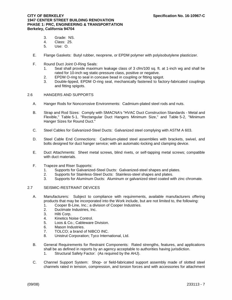
CITY OF BERKELEY Specification No. 16-10967-C 1947 CENTER STREET BUILDING RENOVATION PHASE 1: PRC, ENGINEERING & TRANSPORTATION Berkeley, California 94704
(09/08) 233113 - 7
3. Grade: NS. 4. Class: 25. 5. Use: O.
E. Flange Gaskets: Butyl rubber, neoprene, or EPDM polymer with polyisobutylene plasticizer.
F. Round Duct Joint O-Ring Seals: 1. Seal shall provide maximum leakage class of 3 cfm/100 sq. ft. at 1-inch wg and shall be
rated for 10-inch wg static-pressure class, positive or negative. 2. EPDM O-ring to seal in concave bead in coupling or fitting spigot. 3. Double-lipped, EPDM O-ring seal, mechanically fastened to factory-fabricated couplings
and fitting spigots.
2.6 HANGERS AND SUPPORTS
A. Hanger Rods for Noncorrosive Environments: Cadmium-plated steel rods and nuts.
B. Strap and Rod Sizes: Comply with SMACNA's "HVAC Duct Construction Standards - Metal and Flexible," Table 5-1, "Rectangular Duct Hangers Minimum Size," and Table 5-2, "Minimum Hanger Sizes for Round Duct."
C. Steel Cables for Galvanized-Steel Ducts: Galvanized steel complying with ASTM A 603.
D. Steel Cable End Connections: Cadmium-plated steel assemblies with brackets, swivel, and bolts designed for duct hanger service; with an automatic-locking and clamping device.
E. Duct Attachments: Sheet metal screws, blind rivets, or self-tapping metal screws; compatible with duct materials.
F. Trapeze and Riser Supports: 1. Supports for Galvanized-Steel Ducts: Galvanized-steel shapes and plates. 2. Supports for Stainless-Steel Ducts: Stainless-steel shapes and plates. 3. Supports for Aluminum Ducts: Aluminum or galvanized steel coated with zinc chromate.
2.7 SEISMIC-RESTRAINT DEVICES
A. Manufacturers: Subject to compliance with requirements, available manufacturers offering products that may be incorporated into the Work include, but are not limited to, the following: 1. Cooper B-Line, Inc.; a division of Cooper Industries. 2. Ductmate Industries, Inc. 3. Hilti Corp. 4. Kinetics Noise Control. 5. Loos & Co.; Cableware Division. 6. Mason Industries. 7. TOLCO; a brand of NIBCO INC. 8. Unistrut Corporation; Tyco International, Ltd.
B. General Requirements for Restraint Components: Rated strengths, features, and applications shall be as defined in reports by an agency acceptable to authorities having jurisdiction. 1. Structural Safety Factor: (As required by the AHJ).
C. Channel Support System: Shop- or field-fabricated support assembly made of slotted steel channels rated in tension, compression, and torsion forces and with accessories for attachment

CITY OF BERKELEY Specification No. 16-10967-C 1947 CENTER STREET BUILDING RENOVATION PHASE 1: PRC, ENGINEERING & TRANSPORTATION Berkeley, California 94704
(09/08) 233113 - 8
to braced component at one end and to building structure at the other end. Include matching components and corrosion-resistant coating.
D. Restraint Cables: ASTM A 603, galvanized-steel cables with end connections made of cadmium-plated steel assemblies with brackets, swivel, and bolts designed for restraining cable service; and with an automatic-locking and clamping device or double-cable clips.
E. Hanger Rod Stiffener: Steel tube or steel slotted-support-system sleeve with internally bolted connections or Reinforcing steel angle clamped to hanger rod.
F. Mechanical Anchor Bolts: Drilled-in and stud-wedge or female-wedge type. Select anchor bolts with strength required for anchor and as tested according to ASTM E 488.
PART 3 - EXECUTION
3.1 DUCT INSTALLATION
A. Drawing plans, schematics, and diagrams indicate general location and arrangement of duct system. Indicated duct locations, configurations, and arrangements were used to size ducts and calculate friction loss for air-handling equipment sizing and for other design considerations. Install duct systems as indicated unless deviations to layout are approved on Shop Drawings and Coordination Drawings.
B. Install ducts according to SMACNA's "HVAC Duct Construction Standards - Metal and Flexible" unless otherwise indicated.
C. Install round ducts in maximum practical lengths.
D. Install ducts with fewest possible joints.
E. Install factory- or shop-fabricated fittings for changes in direction, size, and shape and for branch connections.
F. Unless otherwise indicated, install ducts vertically and horizontally, and parallel and perpendicular to building lines.
G. Install ducts close to walls, overhead construction, columns, and other structural and permanent enclosure elements of building.
H. Install ducts with a clearance of 1 inch, plus allowance for insulation thickness.
I. Route ducts to avoid passing through transformer vaults and electrical equipment rooms and enclosures.
J. Where ducts pass through non-fire-rated interior partitions and exterior walls and are exposed to view, cover the opening between the partition and duct or duct insulation with sheet metal flanges of same metal thickness as the duct. Overlap openings on four sides by at least 1-1/2 inches.
K. Protect duct interiors from moisture, construction debris and dust, and other foreign materials. Comply with SMACNA's "IAQ Guidelines for Occupied Buildings Under Construction," Appendix G, "Duct Cleanliness for New Construction Guidelines."

CITY OF BERKELEY Specification No. 16-10967-C 1947 CENTER STREET BUILDING RENOVATION PHASE 1: PRC, ENGINEERING & TRANSPORTATION Berkeley, California 94704
(09/08) 233113 - 9
3.2 INSTALLATION OF EXPOSED DUCTWORK
A. Protect ducts exposed in finished spaces from being dented, scratched, or damaged.
B. Trim duct sealants flush with metal. Create a smooth and uniform exposed bead. Do not use two-part tape sealing system.
C. Grind welds to provide smooth surface free of burrs, sharp edges, and weld splatter. When welding stainless steel with a No. 3 or 4 finish, grind the welds flush, polish the exposed welds, and treat the welds to remove discoloration caused by welding.
D. Maintain consistency, symmetry, and uniformity in the arrangement and fabrication of fittings, hangers and supports, duct accessories, and air outlets.
E. Repair or replace damaged sections and finished work that does not comply with these requirements.
3.3 DUCT SEALING
A. Seal ducts for duct static-pressure, seal classes, and leakage classes specified in "Duct Schedule" Article according to SMACNA's "HVAC Duct Construction Standards - Metal and Flexible."
3.4 HANGER AND SUPPORT INSTALLATION
A. Comply with SMACNA's "HVAC Duct Construction Standards - Metal and Flexible," Chapter 5, "Hangers and Supports."
B. Building Attachments: Concrete inserts, powder-actuated fasteners, or structural-steel fasteners appropriate for construction materials to which hangers are being attached. 1. Where practical, install concrete inserts before placing concrete. 2. Install powder-actuated concrete fasteners after concrete is placed and completely cured. 3. Use powder-actuated concrete fasteners for standard-weight aggregate concretes or for
slabs more than 4 inches thick.
C. Hanger Spacing: Comply with SMACNA's "HVAC Duct Construction Standards - Metal and Flexible," Table 5-1, "Rectangular Duct Hangers Minimum Size," and Table 5-2, "Minimum Hanger Sizes for Round Duct," for maximum hanger spacing; install hangers and supports within 24 inches of each elbow and within 48 inches of each branch intersection.
D. Hangers Exposed to View: Threaded rod and angle or channel supports.
E. Install upper attachments to structures. Select and size upper attachments with pull-out, tension, and shear capacities appropriate for supported loads and building materials where used.
3.5 SEISMIC-RESTRAINT-DEVICE INSTALLATION
A. Install ducts with hangers and braces designed to support the duct and to restrain against seismic forces required by applicable building codes.
B. Select seismic-restraint devices with capacities adequate to carry present and future static and seismic loads.

CITY OF BERKELEY Specification No. 16-10967-C 1947 CENTER STREET BUILDING RENOVATION PHASE 1: PRC, ENGINEERING & TRANSPORTATION Berkeley, California 94704
(09/08) 233113 - 10
C. Install cables so they do not bend across edges of adjacent equipment or building structure.
D. Install cable restraints on ducts that are suspended with vibration isolators.
E. Install seismic-restraint devices using methods approved by an agency acceptable to authorities having jurisdiction.
F. Attachment to Structure: If specific attachment is not indicated, anchor bracing and restraints to structure, to flanges of beams, to upper truss chords of bar joists, or to concrete members.
G. Drilling for and Setting Anchors: 1. Identify position of reinforcing steel and other embedded items prior to drilling holes for
anchors. Do not damage existing reinforcement or embedded items during drilling. Notify the Architect if reinforcing steel or other embedded items are encountered during drilling. Locate and avoid prestressed tendons, electrical and telecommunications conduit, and gas lines.
2. Do not drill holes in concrete or masonry until concrete, mortar, or grout has achieved full design strength.
3. Wedge Anchors: Protect threads from damage during anchor installation. Heavy-duty sleeve anchors shall be installed with sleeve fully engaged in the structural element to which anchor is to be fastened.
4. Set anchors to manufacturer's recommended torque, using a torque wrench. 5. Install zinc-coated steel anchors for interior applications and stainless-steel anchors for
applications exposed to weather.
3.6 CONNECTIONS
A. Make connections to equipment with flexible connectors complying with Section 23 33 00 "Air Duct Accessories."
B. Comply with SMACNA's "HVAC Duct Construction Standards - Metal and Flexible" for branch, outlet and inlet, and terminal unit connections.
3.7 PAINTING
A. Paint interior of metal ducts that are visible through registers and grilles and that do not have duct liner. Apply one coat of flat, black, latex paint over a compatible galvanized-steel primer. Paint materials and application requirements are specified in Section 09 91 23 "Interior Painting."
3.8 FIELD QUALITY CONTROL
A. Perform tests and inspections.
3.9 DUCT CLEANING
A. Clean new duct system(s) before testing, adjusting, and balancing.
B. Use service openings for entry and inspection. 1. Create new openings and install access panels appropriate for duct static-pressure class
if required for cleaning access. Provide insulated panels for insulated or lined duct. Patch insulation and liner as recommended by duct liner manufacturer. Comply with Section 23 33 00 "Air Duct Accessories" for access panels and doors.
2. Disconnect and reconnect flexible ducts as needed for cleaning and inspection.

CITY OF BERKELEY Specification No. 16-10967-C 1947 CENTER STREET BUILDING RENOVATION PHASE 1: PRC, ENGINEERING & TRANSPORTATION Berkeley, California 94704
(09/08) 233113 - 11
3. Remove and reinstall ceiling to gain access during the cleaning process.
C. Particulate Collection and Odor Control: 1. When venting vacuuming system inside the building, use HEPA filtration with 99.97
percent collection efficiency for 0.3-micron-size (or larger) particles. 2. When venting vacuuming system to outdoors, use filter to collect debris removed from
HVAC system, and locate exhaust downwind and away from air intakes and other points of entry into building.
D. Clean the following components by removing surface contaminants and deposits: 1. Air outlets and inlets (registers, grilles, and diffusers). 2. Supply, return, and exhaust fans including fan housings, plenums (except ceiling supply
and return plenums), scrolls, blades or vanes, shafts, baffles, dampers, and drive assemblies.
3. Air-handling unit internal surfaces and components including mixing box, coil section, air wash systems, spray eliminators, condensate drain pans, humidifiers and dehumidifiers, filters and filter sections, and condensate collectors and drains.
4. Coils and related components. 5. Return-air ducts, dampers, actuators, and turning vanes except in ceiling plenums and
mechanical equipment rooms. 6. Supply-air ducts, dampers, actuators, and turning vanes. 7. Dedicated exhaust and ventilation components and makeup air systems.
E. Mechanical Cleaning Methodology: 1. Clean metal duct systems using mechanical cleaning methods that extract contaminants
from within duct systems and remove contaminants from building. 2. Use vacuum-collection devices that are operated continuously during cleaning. Connect
vacuum device to downstream end of duct sections so areas being cleaned are under negative pressure.
3. Use mechanical agitation to dislodge debris adhered to interior duct surfaces without damaging integrity of metal ducts, duct liner, or duct accessories.
4. Clean fibrous-glass duct liner with HEPA vacuuming equipment; do not permit duct liner to get wet. Replace fibrous-glass duct liner that is damaged, deteriorated, or delaminated or that has friable material, mold, or fungus growth.
5. Clean coils and coil drain pans according to NADCA 1992. Keep drain pan operational. Rinse coils with clean water to remove latent residues and cleaning materials; comb and straighten fins.
6. Provide drainage and cleanup for wash-down procedures. 7. Antimicrobial Agents and Coatings: Apply EPA-registered antimicrobial agents if fungus
is present. Apply antimicrobial agents according to manufacturer's written instructions after removal of surface deposits and debris.
3.10 START UP
A. Air Balance: Comply with requirements in Section 23 05 93 "Testing, Adjusting, and Balancing for HVAC."
3.11 DUCT SCHEDULE
A. Fabricate ducts with galvanized sheet steel except as otherwise indicated and as follows:
B. Supply Ducts: 1. All Ducts:
a. Pressure Class: Positive 2-inch wg.

CITY OF BERKELEY Specification No. 16-10967-C 1947 CENTER STREET BUILDING RENOVATION PHASE 1: PRC, ENGINEERING & TRANSPORTATION Berkeley, California 94704
(09/08) 233113 - 12
b. Minimum SMACNA Seal Class: A. c. SMACNA Leakage Class for Rectangular: 12. d. SMACNA Leakage Class for Round and Flat Oval: 12.
C. Liner: 1. Fibrous glass, Type I, 1-1/2 inches thick.
D. Elbow Configuration: 1. Rectangular Duct: Comply with SMACNA's "HVAC Duct Construction Standards - Metal
and Flexible," Figure 4-2, "Rectangular Elbows." a. Velocity 1000 fpm or Lower:
1) Radius Type RE 1 with minimum 0.5 radius-to-diameter ratio. 2) Mitered Type RE 4 without vanes.
b. Velocity 1000 to 1500 fpm: 1) Radius Type RE 1 with minimum 1.0 radius-to-diameter ratio. 2) Radius Type RE 3 with minimum 0.5 radius-to-diameter ratio and two vanes. 3) Mitered Type RE 2 with vanes complying with SMACNA's "HVAC Duct
Construction Standards - Metal and Flexible," Figure 4-3, "Vanes and Vane Runners," and Figure 4-4, "Vane Support in Elbows."
c. Velocity 1500 fpm or Higher: 1) Radius Type RE 1 with minimum 1.5 radius-to-diameter ratio. 2) Radius Type RE 3 with minimum 1.0 radius-to-diameter ratio and two vanes. 3) Mitered Type RE 2 with vanes complying with SMACNA's "HVAC Duct
Construction Standards - Metal and Flexible," Figure 4-3, "Vanes and Vane Runners," and Figure 4-4, "Vane Support in Elbows."
2. Rectangular Duct: Comply with SMACNA's "HVAC Duct Construction Standards - Metal and Flexible," Figure 4-2, "Rectangular Elbows." a. Radius Type RE 1 with minimum 1.5 radius-to-diameter ratio. b. Radius Type RE 3 with minimum 1.0 radius-to-diameter ratio and two vanes. c. Mitered Type RE 2 with vanes complying with SMACNA's "HVAC Duct
Construction Standards - Metal and Flexible," Figure 4-3, "Vanes and Vane Runners," and Figure 4-4, "Vane Support in Elbows."
3. Round Duct: Comply with SMACNA's "HVAC Duct Construction Standards - Metal and Flexible," Figure 3-4, "Round Duct Elbows." a. Minimum Radius-to-Diameter Ratio and Elbow Segments: Comply with
SMACNA's "HVAC Duct Construction Standards - Metal and Flexible," Table 3-1, "Mitered Elbows." Elbows with less than 90-degree change of direction have proportionately fewer segments. 1) Velocity 1000 fpm or Lower: 0.5 radius-to-diameter ratio and three
segments for 90-degree elbow. 2) Velocity 1000 to 1500 fpm: 1.0 radius-to-diameter ratio and four segments
for 90-degree elbow. 3) Velocity 1500 fpm or Higher: 1.5 radius-to-diameter ratio and five segments
for 90-degree elbow. 4) Radius-to Diameter Ratio: 1.5.
b. Round Elbows, 12 Inches and Smaller in Diameter: Stamped or pleated. c. Round Elbows, 14 Inches and Larger in Diameter: [Standing seam][Welded].
E. Branch Configuration: 1. Rectangular Duct: Comply with SMACNA's "HVAC Duct Construction Standards - Metal
and Flexible," Figure 4-6, "Branch Connection." a. Rectangular Main to Rectangular Branch: 45-degree entry. b. Rectangular Main to Round Branch: Spin in.

CITY OF BERKELEY Specification No. 16-10967-C 1947 CENTER STREET BUILDING RENOVATION PHASE 1: PRC, ENGINEERING & TRANSPORTATION Berkeley, California 94704
(09/08) 233113 - 13
2. Round and Flat Oval: Comply with SMACNA's "HVAC Duct Construction Standards - Metal and Flexible," Figure 3-5, "90 Degree Tees and Laterals," and Figure 3-6, "Conical Tees." Saddle taps are permitted in existing duct. a. Velocity 1000 fpm or Lower: 90-degree tap. b. Velocity 1000 to 1500 fpm: Conical tap. c. Velocity 1500 fpm or Higher: 45-degree lateral.
END OF SECTION
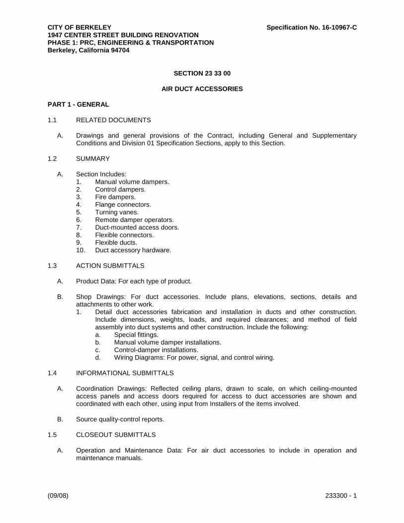
CITY OF BERKELEY Specification No. 16-10967-C 1947 CENTER STREET BUILDING RENOVATION PHASE 1: PRC, ENGINEERING & TRANSPORTATION Berkeley, California 94704
(09/08) 233300 - 1
SECTION 23 33 00
AIR DUCT ACCESSORIES
PART 1 - GENERAL
1.1 RELATED DOCUMENTS
A. Drawings and general provisions of the Contract, including General and Supplementary Conditions and Division 01 Specification Sections, apply to this Section.
1.2 SUMMARY
A. Section Includes: 1. Manual volume dampers. 2. Control dampers. 3. Fire dampers. 4. Flange connectors. 5. Turning vanes. 6. Remote damper operators. 7. Duct-mounted access doors. 8. Flexible connectors. 9. Flexible ducts. 10. Duct accessory hardware.
1.3 ACTION SUBMITTALS
A. Product Data: For each type of product.
B. Shop Drawings: For duct accessories. Include plans, elevations, sections, details and attachments to other work. 1. Detail duct accessories fabrication and installation in ducts and other construction.
Include dimensions, weights, loads, and required clearances; and method of field assembly into duct systems and other construction. Include the following: a. Special fittings. b. Manual volume damper installations. c. Control-damper installations. d. Wiring Diagrams: For power, signal, and control wiring.
1.4 INFORMATIONAL SUBMITTALS
A. Coordination Drawings: Reflected ceiling plans, drawn to scale, on which ceiling-mounted access panels and access doors required for access to duct accessories are shown and coordinated with each other, using input from Installers of the items involved.
B. Source quality-control reports.
1.5 CLOSEOUT SUBMITTALS
A. Operation and Maintenance Data: For air duct accessories to include in operation and maintenance manuals.
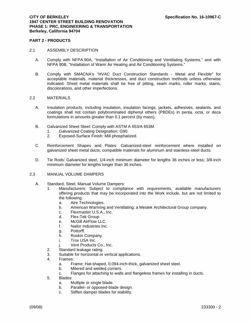
CITY OF BERKELEY Specification No. 16-10967-C 1947 CENTER STREET BUILDING RENOVATION PHASE 1: PRC, ENGINEERING & TRANSPORTATION Berkeley, California 94704
(09/08) 233300 - 2
PART 2 - PRODUCTS
2.1 ASSEMBLY DESCRIPTION
A. Comply with NFPA 90A, "Installation of Air Conditioning and Ventilating Systems," and with NFPA 90B, "Installation of Warm Air Heating and Air Conditioning Systems."
B. Comply with SMACNA's "HVAC Duct Construction Standards - Metal and Flexible" for acceptable materials, material thicknesses, and duct construction methods unless otherwise indicated. Sheet metal materials shall be free of pitting, seam marks, roller marks, stains, discolorations, and other imperfections.
2.2 MATERIALS
A. Insulation products, including insulation, insulation facings, jackets, adhesives, sealants, and coatings shall not contain polybrominated diphenyl ethers (PBDEs) in penta, octa, or deca formulations in amounts greater than 0.1 percent (by mass).
B. Galvanized Sheet Steel: Comply with ASTM A 653/A 653M. 1. Galvanized Coating Designation: G90. 2. Exposed-Surface Finish: Mill phosphatized.
C. Reinforcement Shapes and Plates: Galvanized-steel reinforcement where installed on galvanized sheet metal ducts; compatible materials for aluminum and stainless-steel ducts.
D. Tie Rods: Galvanized steel, 1/4-inch minimum diameter for lengths 36 inches or less; 3/8-inch minimum diameter for lengths longer than 36 inches.
2.3 MANUAL VOLUME DAMPERS
A. Standard, Steel, Manual Volume Dampers: 1. Manufacturers: Subject to compliance with requirements, available manufacturers
offering products that may be incorporated into the Work include, but are not limited to the following: a. Aire Technologies. b. American Warming and Ventilating; a Mestek Architectural Group company. c. Flexmaster U.S.A., Inc. d. Flex-Tek Group. e. McGill AirFlow LLC. f. Nailor Industries Inc. g. Pottorff. h. Ruskin Company. i. Trox USA Inc. j. Vent Products Co., Inc.
2. Standard leakage rating. 3. Suitable for horizontal or vertical applications. 4. Frames:
a. Frame: Hat-shaped, 0.094-inch-thick, galvanized sheet steel. b. Mitered and welded corners. c. Flanges for attaching to walls and flangeless frames for installing in ducts.
5. Blades: a. Multiple or single blade. b. Parallel- or opposed-blade design. c. Stiffen damper blades for stability.

CITY OF BERKELEY Specification No. 16-10967-C 1947 CENTER STREET BUILDING RENOVATION PHASE 1: PRC, ENGINEERING & TRANSPORTATION Berkeley, California 94704
(09/08) 233300 - 3
d. Galvanized-steel, 0.064 inch thick. 6. Blade Axles: Galvanized steel. 7. Bearings:
a. Stainless-steel sleeve. b. Dampers in ducts with pressure classes of 3-inch wg or less shall have axles full
length of damper blades and bearings at both ends of operating shaft. 8. Tie Bars and Brackets: Galvanized steel.
B. Standard, Aluminum, Manual Volume Dampers: 1. Manufacturers: Subject to compliance with requirements, available manufacturers
offering products that may be incorporated into the Work include, but are not limited to the following: a. American Warming and Ventilating; a Mestek Architectural Group company. b. McGill AirFlow LLC. c. Nailor Industries Inc. d. Pottorff. e. Ruskin Company. f. Trox USA Inc. g. Vent Products Co., Inc.
2. Standard leakage rating, with linkage outside airstream. 3. Suitable for horizontal or vertical applications. 4. Frames: Hat-shaped, 0.10-inch-thick, aluminum sheet channels; frames with flanges for
attaching to walls and flangeless frames for installing in ducts. 5. Blades:
a. Multiple or single blade. b. Parallel- or opposed-blade design. c. Stiffen damper blades for stability. d. Roll-Formed Aluminum Blades: 0.10-inch-thick aluminum sheet. e. Extruded-Aluminum Blades: 0.050-inch-thick extruded aluminum.
6. Blade Axles: Galvanized steel. 7. Bearings:
a. Stainless-steel sleeve. b. Dampers in ducts with pressure classes of 3-inch wg or less shall have axles full
length of damper blades and bearings at both ends of operating shaft. 8. Tie Bars and Brackets: Aluminum.
C. Low-Leakage, Steel, Manual Volume Dampers: 1. Manufacturers: Subject to compliance with requirements, available manufacturers
offering products that may be incorporated into the Work include, but are not limited to the following: a. American Warming and Ventilating; a Mestek Architectural Group company. b. Flex-Tek Group. c. McGill AirFlow LLC. d. Nailor Industries Inc. e. Pottorff. f. Ruskin Company. g. Trox USA Inc. h. Vent Products Co., Inc.
2. Comply with AMCA 500-D testing for damper rating. 3. Low-leakage rating, with linkage outside airstream, and bearing AMCA's Certified Ratings
Seal for both air performance and air leakage. 4. Suitable for horizontal or vertical applications. 5. Frames:
a. Hat shaped.
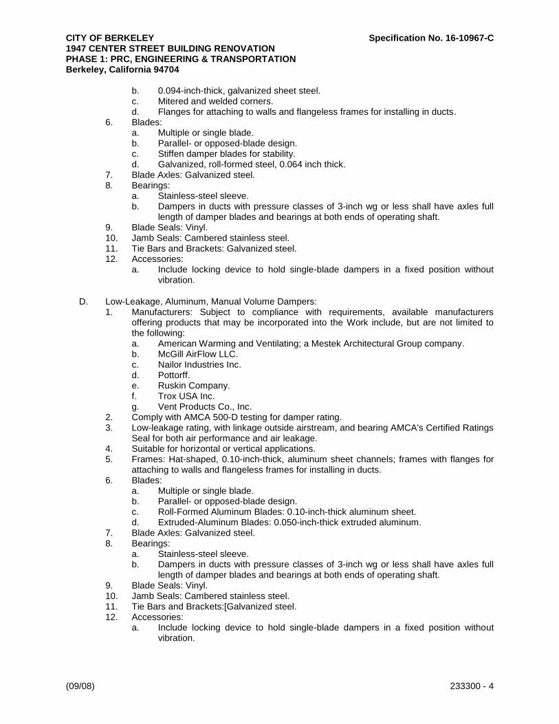
CITY OF BERKELEY Specification No. 16-10967-C 1947 CENTER STREET BUILDING RENOVATION PHASE 1: PRC, ENGINEERING & TRANSPORTATION Berkeley, California 94704
(09/08) 233300 - 4
b. 0.094-inch-thick, galvanized sheet steel. c. Mitered and welded corners. d. Flanges for attaching to walls and flangeless frames for installing in ducts.
6. Blades: a. Multiple or single blade. b. Parallel- or opposed-blade design. c. Stiffen damper blades for stability. d. Galvanized, roll-formed steel, 0.064 inch thick.
7. Blade Axles: Galvanized steel. 8. Bearings:
a. Stainless-steel sleeve. b. Dampers in ducts with pressure classes of 3-inch wg or less shall have axles full
length of damper blades and bearings at both ends of operating shaft. 9. Blade Seals: Vinyl. 10. Jamb Seals: Cambered stainless steel. 11. Tie Bars and Brackets: Galvanized steel. 12. Accessories:
a. Include locking device to hold single-blade dampers in a fixed position without vibration.
D. Low-Leakage, Aluminum, Manual Volume Dampers: 1. Manufacturers: Subject to compliance with requirements, available manufacturers
offering products that may be incorporated into the Work include, but are not limited to the following: a. American Warming and Ventilating; a Mestek Architectural Group company. b. McGill AirFlow LLC. c. Nailor Industries Inc. d. Pottorff. e. Ruskin Company. f. Trox USA Inc. g. Vent Products Co., Inc.
2. Comply with AMCA 500-D testing for damper rating. 3. Low-leakage rating, with linkage outside airstream, and bearing AMCA's Certified Ratings
Seal for both air performance and air leakage. 4. Suitable for horizontal or vertical applications. 5. Frames: Hat-shaped, 0.10-inch-thick, aluminum sheet channels; frames with flanges for
attaching to walls and flangeless frames for installing in ducts. 6. Blades:
a. Multiple or single blade. b. Parallel- or opposed-blade design. c. Roll-Formed Aluminum Blades: 0.10-inch-thick aluminum sheet. d. Extruded-Aluminum Blades: 0.050-inch-thick extruded aluminum.
7. Blade Axles: Galvanized steel. 8. Bearings:
a. Stainless-steel sleeve. b. Dampers in ducts with pressure classes of 3-inch wg or less shall have axles full
length of damper blades and bearings at both ends of operating shaft. 9. Blade Seals: Vinyl. 10. Jamb Seals: Cambered stainless steel. 11. Tie Bars and Brackets:[Galvanized steel. 12. Accessories:
a. Include locking device to hold single-blade dampers in a fixed position without vibration.

CITY OF BERKELEY Specification No. 16-10967-C 1947 CENTER STREET BUILDING RENOVATION PHASE 1: PRC, ENGINEERING & TRANSPORTATION Berkeley, California 94704
(09/08) 233300 - 5
E. Jackshaft: 1. Size: 0.5-inch diameter. 2. Material: Galvanized-steel pipe rotating within pipe-bearing assembly mounted on
supports at each mullion and at each end of multiple-damper assemblies. 3. Length and Number of Mountings: As required to connect linkage of each damper in
multiple-damper assembly.
F. Damper Hardware: 1. Zinc-plated, die-cast core with dial and handle made of 3/32-inch-thick zinc-plated steel,
and a 3/4-inch hexagon locking nut. 2. Include center hole to suit damper operating-rod size. 3. Include elevated platform for insulated duct mounting.
2.4 CONTROL DAMPERS
A. Manufacturers: Subject to compliance with requirements, available manufacturers offering products that may be incorporated into the Work include, but are not limited to the following: 1. American Warming and Ventilating; a Mestek Architectural Group company. 2. Arrow United Industries. 3. Cesco Products; a divsion of MESTEK, Inc. 4. Flex-Tek Group. 5. Greenheck Fan Corporation. 6. Lloyd Industries, Inc. 7. McGill AirFlow LLC. 8. Metal Form Manufacturing, Inc. 9. Nailor Industries Inc. 10. NCA Manufacturing, Inc. 11. Pottorff. 12. Ruskin Company. 13. Vent Products Co., Inc. 14. Young Regulator Company.
B. Low-leakage rating, with linkage outside airstream, and bearing AMCA's Certified Ratings Seal for both air performance and air leakage.
C. Frames: 1. Hat shaped. 2. 0.094-inch-thick, galvanized sheet steel. 3. Mitered and welded corners.
D. Blades: 1. Multiple blade with maximum blade width of 6 inches. 2. Opposed-blade design. 3. Galvanized-steel. 4. 0.064 inch thick single skin. 5. Blade Edging: Closed-cell neoprene. 6. Blade Edging: Inflatable seal blade edging, or replaceable rubber seals.
E. Blade Axles: 1/2-inch-diameter; galvanized steel; blade-linkage hardware of zinc-plated steel and brass; ends sealed against blade bearings. 1. Operating Temperature Range: From minus 40 to plus 200 deg F.
F. Bearings: 1. Stainless-steel sleeve.

CITY OF BERKELEY Specification No. 16-10967-C 1947 CENTER STREET BUILDING RENOVATION PHASE 1: PRC, ENGINEERING & TRANSPORTATION Berkeley, California 94704
(09/08) 233300 - 6
2. Dampers in ducts with pressure classes of 3-inch wg or less shall have axles full length of damper blades and bearings at both ends of operating shaft.
3. Thrust bearings at each end of every blade. 4. .
2.5 FLANGE CONNECTORS
A. Manufacturers: Subject to compliance with requirements, available manufacturers offering products that may be incorporated into the Work include, but are not limited to the following: 1. Ductmate Industries, Inc. 2. Hardcast, Inc. 3. Nexus PDQ. 4. Ward Industries, Inc.
B. Description: roll-formed, factory-fabricated, slide-on transverse flange connectors, gaskets, and components.
C. Material: Galvanized steel.
D. Gage and Shape: Match connecting ductwork.
2.6 TURNING VANES
A. Manufacturers: Subject to compliance with requirements, available manufacturers offering products that may be incorporated into the Work include, but are not limited to the following: 1. Aero-Dyne Sound Control Co. 2. Ductmate Industries, Inc. 3. Duro Dyne Inc. 4. Elgen Manufacturing. 5. Hardcast, Inc. 6. METALAIRE, Inc. 7. SEMCO Incorporated. 8. Ward Industries, Inc.
B. Manufactured Turning Vanes for Metal Ducts: Curved blades of galvanized sheet steel; support with bars perpendicular to blades set; set into vane runners suitable for duct mounting. 1. Acoustic Turning Vanes: Fabricate airfoil-shaped aluminum extrusions with perforated
faces and fibrous-glass fill.
C. Manufactured Turning Vanes for Nonmetal Ducts: Fabricate curved blades of resin-bonded fiberglass with acrylic polymer coating; support with bars perpendicular to blades set; set into vane runners suitable for duct mounting.
D. General Requirements: Comply with SMACNA's "HVAC Duct Construction Standards - Metal and Flexible"; Figures 4-3, "Vanes and Vane Runners," and 4-4, "Vane Support in Elbows."
E. Vane Construction: Single wall.
2.7 REMOTE DAMPER OPERATORS
A. Manufacturers: Subject to compliance with requirements, available manufacturers offering products that may be incorporated into the Work include, but are not limited to the following: 1. Pottorff. 2. Ventfabrics, Inc.

CITY OF BERKELEY Specification No. 16-10967-C 1947 CENTER STREET BUILDING RENOVATION PHASE 1: PRC, ENGINEERING & TRANSPORTATION Berkeley, California 94704
(09/08) 233300 - 7
3. Young Regulator Company.
B. Description: Cable system designed for remote manual damper adjustment.
C. Tubing: Aluminum.
D. Cable: Stainless steel.
E. Wall-Box Mounting: Recessed.
F. Wall-Box Cover-Plate Material: Stainless steel.
2.8 DUCT-MOUNTED ACCESS DOORS
A. Manufacturers: Subject to compliance with requirements, available manufacturers offering products that may be incorporated into the Work include, but are not limited to the following: 1. Aire Technologies. 2. American Warming and Ventilating; a Mestek Architectural Group company. 3. Cesco Products; a divsion of MESTEK, Inc. 4. Ductmate Industries, Inc. 5. Elgen Manufacturing. 6. Flexmaster U.S.A., Inc. 7. Greenheck Fan Corporation. 8. McGill AirFlow LLC. 9. Nailor Industries Inc. 10. Pottorff. 11. Ventfabrics, Inc. 12. Ward Industries, Inc.
B. Duct-Mounted Access Doors: Fabricate access panels according to SMACNA's "HVAC Duct Construction Standards - Metal and Flexible"; Figures 7-2, "Duct Access Doors and Panels," and 7-3, "Access Doors - Round Duct." 1. Door:
a. Double wall, rectangular. b. Galvanized sheet metal with insulation fill and thickness as indicated for duct
pressure class. c. Vision panel. d. Hinges and Latches: 1-by-1-inchbutt or piano hinge and cam latches. e. Fabricate doors airtight and suitable for duct pressure class.
2. Frame: Galvanized sheet steel, with bend-over tabs and foam gaskets. 3. Number of Hinges and Locks:
a. Access Doors Less Than 12 Inches Square: No hinges and two sash locks. b. Access Doors up to 18 Inches Square: Two hinges and two sash locks.
2.9 FLEXIBLE CONNECTORS
A. Manufacturers: Subject to compliance with requirements, available manufacturers offering products that may be incorporated into the Work include, but are not limited to the following: 1. Ductmate Industries, Inc. 2. Duro Dyne Inc. 3. Elgen Manufacturing. 4. Hardcast, Inc. 5. JP Lamborn Co. 6. Ventfabrics, Inc.

CITY OF BERKELEY Specification No. 16-10967-C 1947 CENTER STREET BUILDING RENOVATION PHASE 1: PRC, ENGINEERING & TRANSPORTATION Berkeley, California 94704
(09/08) 233300 - 8
7. Ward Industries, Inc.
B. Materials: Flame-retardant or noncombustible fabrics.
C. Coatings and Adhesives: Comply with UL 181, Class 1.
D. Metal-Edged Connectors: Factory fabricated with a fabric strip 3-1/2 inches wide attached to two strips of 2-3/4-inch-wide, 0.028-inch-thick, galvanized sheet steel or 0.032-inch-thick aluminum sheets. Provide metal compatible with connected ducts.
E. Indoor System, Flexible Connector Fabric: Glass fabric double coated with neoprene. 1. Minimum Weight: 26 oz./sq. yd.. 2. Tensile Strength: 480 lbf/inch in the warp and 360 lbf/inch in the filling. 3. Service Temperature: Minus 40 to plus 200 deg F.
2.10 FLEXIBLE DUCTS
A. Manufacturers: Subject to compliance with requirements, available manufacturers offering products that may be incorporated into the Work include, but are not limited to the following: 1. Flexmaster U.S.A., Inc. 2. Flex-Tek Group. 3. JP Lamborn Co. 4. McGill AirFlow LLC. 5. Ward Industries, Inc.
B. Insulated, Flexible Duct: UL 181, Class 1, black polymer film supported by helically wound, spring-steel wire; fibrous-glass insulation; polyethylene vapor-barrier film. 1. Pressure Rating: 4-inch wg positive and 0.5-inch wg negative. 2. Maximum Air Velocity: 4000 fpm. 3. Temperature Range: Minus 20 to plus 175 deg F. 4. Insulation R-Value: Comply with ASHRAE/IESNA 90.1.
C. Flexible Duct Connectors: 1. Clamps: Stainless-steel band with cadmium-plated hex screw to tighten band with a
worm-gear action in sizes 3 through 18 inches, to suit duct size. 2. Non-Clamp Connectors: Liquid adhesive plus tape.
PART 3 - EXECUTION
3.1 INSTALLATION
A. Install duct accessories according to applicable details in SMACNA's "HVAC Duct Construction Standards - Metal and Flexible" for metal ducts and in NAIMA AH116, "Fibrous Glass Duct Construction Standards," for fibrous-glass ducts.
B. Install duct accessories of materials suited to duct materials; use galvanized-steel accessories in galvanized-steel and fibrous-glass ducts, stainless-steel accessories in stainless-steel ducts, and aluminum accessories in aluminum ducts.
C. Install volume dampers at points on supply, return, and exhaust systems where branches extend from larger ducts. Where dampers are installed in ducts having duct liner, install dampers with hat channels of same depth as liner, and terminate liner with nosing at hat channel. 1. Install steel volume dampers in steel ducts.
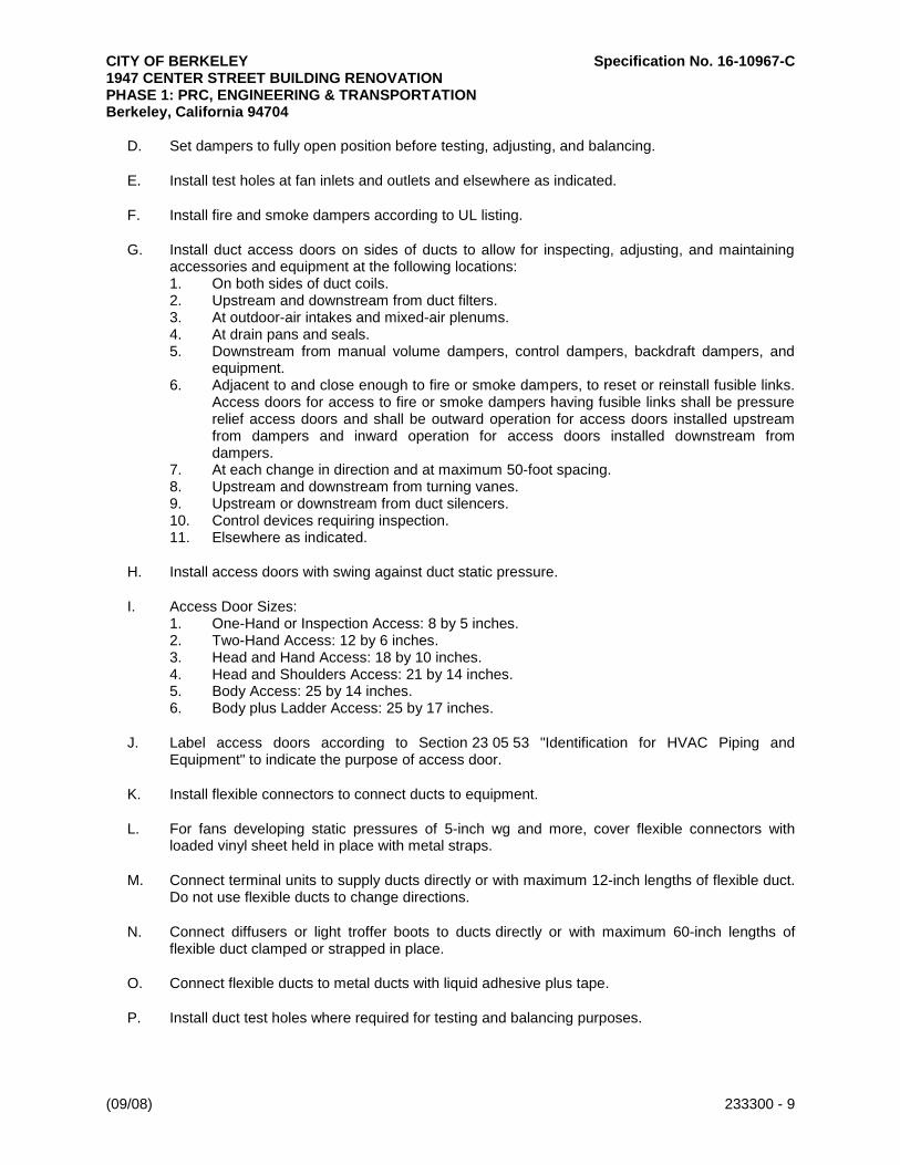
CITY OF BERKELEY Specification No. 16-10967-C 1947 CENTER STREET BUILDING RENOVATION PHASE 1: PRC, ENGINEERING & TRANSPORTATION Berkeley, California 94704
(09/08) 233300 - 9
D. Set dampers to fully open position before testing, adjusting, and balancing.
E. Install test holes at fan inlets and outlets and elsewhere as indicated.
F. Install fire and smoke dampers according to UL listing.
G. Install duct access doors on sides of ducts to allow for inspecting, adjusting, and maintaining accessories and equipment at the following locations: 1. On both sides of duct coils. 2. Upstream and downstream from duct filters. 3. At outdoor-air intakes and mixed-air plenums. 4. At drain pans and seals. 5. Downstream from manual volume dampers, control dampers, backdraft dampers, and
equipment. 6. Adjacent to and close enough to fire or smoke dampers, to reset or reinstall fusible links.
Access doors for access to fire or smoke dampers having fusible links shall be pressure relief access doors and shall be outward operation for access doors installed upstream from dampers and inward operation for access doors installed downstream from dampers.
7. At each change in direction and at maximum 50-foot spacing. 8. Upstream and downstream from turning vanes. 9. Upstream or downstream from duct silencers. 10. Control devices requiring inspection. 11. Elsewhere as indicated.
H. Install access doors with swing against duct static pressure.
I. Access Door Sizes: 1. One-Hand or Inspection Access: 8 by 5 inches. 2. Two-Hand Access: 12 by 6 inches. 3. Head and Hand Access: 18 by 10 inches. 4. Head and Shoulders Access: 21 by 14 inches. 5. Body Access: 25 by 14 inches. 6. Body plus Ladder Access: 25 by 17 inches.
J. Label access doors according to Section 23 05 53 "Identification for HVAC Piping and Equipment" to indicate the purpose of access door.
K. Install flexible connectors to connect ducts to equipment.
L. For fans developing static pressures of 5-inch wg and more, cover flexible connectors with loaded vinyl sheet held in place with metal straps.
M. Connect terminal units to supply ducts directly or with maximum 12-inch lengths of flexible duct. Do not use flexible ducts to change directions.
N. Connect diffusers or light troffer boots to ducts directly or with maximum 60-inch lengths of flexible duct clamped or strapped in place.
O. Connect flexible ducts to metal ducts with liquid adhesive plus tape.
P. Install duct test holes where required for testing and balancing purposes.

CITY OF BERKELEY Specification No. 16-10967-C 1947 CENTER STREET BUILDING RENOVATION PHASE 1: PRC, ENGINEERING & TRANSPORTATION Berkeley, California 94704
(09/08) 233300 - 10
3.2 FIELD QUALITY CONTROL
A. Tests and Inspections: 1. Operate dampers to verify full range of movement. 2. Inspect locations of access doors and verify that purpose of access door can be
performed. 3. Operate fire, smoke, and combination fire and smoke dampers to verify full range of
movement and verify that proper heat-response device is installed. 4. Inspect turning vanes for proper and secure installation. 5. Operate remote damper operators to verify full range of movement of operator and
damper.
END OF SECTION

CITY OF BERKELEY Specification No. 16-10967-C 1947 CENTER STREET BUILDING RENOVATION PHASE 1: PRC, ENGINEERING & TRANSPORTATION Berkeley, California 94704
(09/08) 233713 - 1
SECTION 23 37 13
DIFFUSERS, REGISTERS, AND GRILLES
PART 1 - GENERAL
1.1 RELATED DOCUMENTS
A. Drawings and general provisions of the Contract, including General and Supplementary Conditions and Division 01 Specification Sections, apply to this Section.
1.2 SUMMARY
A. Section Includes: 1. Rectangular and square ceiling diffusers. 2. Perforated diffusers. 3. Louver face diffusers. 4. Modular core supply grilles.
B. Related Sections: 1. Section 23 33 00 "Air Duct Accessories" for fire and smoke dampers and volume-control
dampers not integral to diffusers, registers, and grilles.
1.3 ACTION SUBMITTALS
A. Product Data: For each type of product indicated, include the following: 1. Data Sheet: Indicate materials of construction, finish, and mounting details; and
performance data including throw and drop, static-pressure drop, and noise ratings. 2. Diffuser, Register, and Grille Schedule: Indicate drawing designation, room location,
quantity, model number, size, and accessories furnished.
B. Samples for Initial Selection: For diffusers, registers, and grilles with factory-applied color finishes.
C. Samples for Verification: For diffusers, registers, and grilles, in manufacturer's standard sizes to verify color selected.
1.4 INFORMATIONAL SUBMITTALS
A. Coordination Drawings: Reflected ceiling plans, drawn to scale, on which the following items are shown and coordinated with each other, using input from Installers of the items involved: 1. Ceiling suspension assembly members. 2. Method of attaching hangers to building structure. 3. Size and location of initial access modules for acoustical tile. 4. Ceiling-mounted items including lighting fixtures, diffusers, grilles, speakers, sprinklers,
access panels, and special moldings. 5. Duct access panels.
B. Source quality-control reports.

CITY OF BERKELEY Specification No. 16-10967-C 1947 CENTER STREET BUILDING RENOVATION PHASE 1: PRC, ENGINEERING & TRANSPORTATION Berkeley, California 94704
(09/08) 233713 - 2
PART 2 - PRODUCTS
2.1 CEILING DIFFUSERS
A. Rectangular and Square Ceiling Diffusers : 1. Manufacturers: Subject to compliance with requirements, available manufacturers
offering products that may be incorporated into the Work include, but are not limited to the following: a. Carnes Company. b. Krueger. c. METALAIRE, Inc. d. Nailor Industries Inc. e. Price Industries. f. Titus. g. Tuttle & Bailey.
2. Devices shall be specifically designed for variable-air-volume flows. 3. Material: Aluminum. 4. Finish: Baked enamel, white. 5. Face Size: 24 by 24 inches, 12 by 12 inches. 6. Face Style: Four cone. 7. Mounting: Surface, T-bar. 8. Pattern: Adjustable. 9. Dampers: Combination damper and grid. 10. Accessories:
a. Equalizing grid. b. Plaster ring. c. Safety chain. d. Wire guard. e. Sectorizing baffles. f. Operating rod extension.
B. Perforated Diffuser: 1. Manufacturers: Subject to compliance with requirements, available manufacturers
offering products that may be incorporated into the Work include, but are not limited to the following: a. Carnes Company. b. Krueger. c. METALAIRE, Inc. d. Nailor Industries Inc. e. Titus. f. Tuttle & Bailey.
2. Devices shall be specifically designed for variable-air-volume flows. 3. Material: Steel backpan and pattern controllers, with aluminum face. 4. Finish: Baked enamel, white. 5. Face Size:12 by 12 inches, 24 by 24 inches. 6. Duct Inlet: Round. 7. Face Style: Flush. 8. Mounting: Surface, T-bar . 9. Pattern Controller: Four louvered deflector patches. 10. Dampers: Combination damper and grid. 11. Accessories:
a. Equalizing grid. b. Plaster ring. c. Safety chain.

CITY OF BERKELEY Specification No. 16-10967-C 1947 CENTER STREET BUILDING RENOVATION PHASE 1: PRC, ENGINEERING & TRANSPORTATION Berkeley, California 94704
(09/08) 233713 - 3
d. Wire guard. e. Sectorizing baffles. f. Operating rod extension.
C. Louver Face Diffuser : 1. Manufacturers: Subject to compliance with requirements, available manufacturers
offering products that may be incorporated into the Work include, but are not limited to the following: a. Carnes Company. b. METALAIRE, Inc. c. Nailor Industries Inc. d. Price Industries. e. Titus. f. Tuttle & Bailey.
2. Devices shall be specifically designed for variable-air-volume flows. 3. Material: Aluminum. 4. Finish: Baked enamel, white. 5. Face Size: 24x24 inches. 6. Mounting: Surface, T-bar. 7. Pattern: Three-way, Four-way Adjustable core style. 8. Dampers: Combination damper and grid. 9. Accessories:
a. Square to round neck adaptor. b. Adjustable pattern vanes. c. Throw reducing vanes. d. Equalizing grid. e. Plaster ring. f. Safety chain. g. Wire guard. h. Sectorizing baffles. i. Operating rod extension.
D. Modular Core Supply Grilles: 1. Manufacturers: Subject to compliance with requirements, available manufacturers
offering products that may be incorporated into the Work include, but are not limited to the following: a. . b. Carnes Company. c. Hart & Cooley Inc. d. Krueger. e. METALAIRE, Inc. f. Nailor Industries Inc. g. Price Industries. h. Titus. i. Tuttle & Bailey.
2. Throw: Extended distance for airflow rates. 3. Material: Steel. 4. Grilles per Unit: One, Two. 5. Finish: White baked acrylic. 6. Border: 1-1/2-inch width with countersunk screw holes. 7. Blades:
a. Airfoil, individually adjustable horizontally. b. Double deflection. c. Set in modules.

CITY OF BERKELEY Specification No. 16-10967-C 1947 CENTER STREET BUILDING RENOVATION PHASE 1: PRC, ENGINEERING & TRANSPORTATION Berkeley, California 94704
(09/08) 233713 - 4
8. Modules: Removable; rotatable. 9. Mounting: Surface. 10. Accessory: Opposed-blade steel damper.
2.2 REGISTERS AND GRILLES
A. Adjustable Bar Register : 1. Manufacturers: Subject to compliance with requirements, available manufacturers
offering products that may be incorporated into the Work include, but are not limited to the following: a. Carnes Company. b. Hart & Cooley Inc. c. Krueger. d. METALAIRE, Inc. e. Nailor Industries Inc. f. Price Industries. g. Titus. h. Tuttle & Bailey.
2. Material: Aluminum. 3. Finish: Baked enamel, white. 4. Face Blade Arrangement: Horizontal spaced 1/2 inch apart. 5. Core Construction: Removable. 6. Rear-Blade Arrangement: Vertical spaced 3/4 inch apart. 7. Frame: 1 inch wide. 8. Mounting: Countersunk screw, Lay in. 9. Damper Type: Adjustable opposed blade. 10. Accessories:
a. Front -blade gang operator.
B. Fixed Face Grille : 1. Manufacturers: Subject to compliance with requirements, available manufacturers
offering products that may be incorporated into the Work include, but are not limited to the following: a. Carnes Company. b. . c. Hart & Cooley Inc. d. Krueger. e. Nailor Industries Inc. f. Price Industries. g. Titus. h. Tuttle & Bailey.
2. Material: Aluminum. 3. Finish: Baked enamel, white. 4. Face Arrangement: Perforated core. 5. Core Construction: Removable. 6. Frame: 1-1/4 inches wide. 7. Mounting: Countersunk screw, Lay in.
2.3 SOURCE QUALITY CONTROL
A. Verification of Performance: Rate diffusers, registers, and grilles according to ASHRAE 70, "Method of Testing for Rating the Performance of Air Outlets and Inlets."

CITY OF BERKELEY Specification No. 16-10967-C 1947 CENTER STREET BUILDING RENOVATION PHASE 1: PRC, ENGINEERING & TRANSPORTATION Berkeley, California 94704
(09/08) 233713 - 5
PART 3 - EXECUTION
3.1 EXAMINATION
A. Examine areas where diffusers, registers, and grilles are to be installed for compliance with requirements for installation tolerances and other conditions affecting performance of equipment.
B. Proceed with installation only after unsatisfactory conditions have been corrected.
3.2 INSTALLATION
A. Install diffusers, registers, and grilles level and plumb.
B. Ceiling-Mounted Outlets and Inlets: Drawings indicate general arrangement of ducts, fittings, and accessories. Air outlet and inlet locations have been indicated to achieve design requirements for air volume, noise criteria, airflow pattern, throw, and pressure drop. Make final locations where indicated, as much as practical. For units installed in lay-in ceiling panels, locate units in the center of panel. Where architectural features or other items conflict with installation, notify Architect for a determination of final location.
C. Install diffusers, registers, and grilles with airtight connections to ducts and to allow service and maintenance of dampers, air extractors, and fire dampers.
3.3 ADJUSTING
A. After installation, adjust diffusers, registers, and grilles to air patterns indicated, or as directed, before starting air balancing.
END OF SECTION

CITY OF BERKELEY Specification No. 16-10967-C 1947 CENTER STREET BUILDING RENOVATION PHASE 1: PRC, ENGINEERING & TRANSPORTATION Berkeley, California 94704
(09/08) 234100 - 1
SECTION 23 41 00
PARTICULATE AIR FILTRATION
PART 1 - GENERAL
1.1 RELATED DOCUMENTS
A. Drawings and general provisions of the Contract, including General and Supplementary Conditions and Division 01 Specification Sections, apply to this Section.
1.2 SUMMARY
A. Section Includes: 1. Flat panel filters. 2. Pleated panel filters. 3. Filter gages.
1.3 ACTION SUBMITTALS
A. Product Data: For each type of product indicated. Include dimensions; operating characteristics; required clearances and access; rated flow capacity, including initial and final pressure drop at rated airflow; efficiency and test method; fire classification; furnished specialties; and accessories for each model indicated.
B. Shop Drawings: For air filters. Include plans, elevations, sections, details, and attachments to other work. 1. Show filter rack assembly, dimensions, materials, and methods of assembly of
components. 2. Include setting drawings, templates, and requirements for installing anchor bolts and
anchorages. 3. Wiring Diagrams: For power, signal, and control wiring.
1.4 CLOSEOUT SUBMITTALS
A. Operation and Maintenance Data: For each type of filter and rack to include in emergency, operation, and maintenance manuals.
1.5 MAINTENANCE MATERIAL SUBMITTALS
A. Furnish extra materials that match products installed and that are packaged with protective covering for storage and identified with labels describing contents. 1. Provide [two] complete set(s) of filters for each filter bank. If system includes prefilters,
provide only prefilters.
1.6 QUALITY ASSURANCE
A. Electrical Components, Devices, and Accessories: Listed and labeled as defined in NFPA 70, by a qualified testing agency, and marked for intended location and application.
B. ASHRAE Compliance:

CITY OF BERKELEY Specification No. 16-10967-C 1947 CENTER STREET BUILDING RENOVATION PHASE 1: PRC, ENGINEERING & TRANSPORTATION Berkeley, California 94704
(09/08) 234100 - 2
1. Comply with applicable requirements in ASHRAE 62.1, Section 4 - "Outdoor Air Quality"; Section 5 - "Systems and Equipment"; and Section 7 - "Construction and Startup."
2. Comply with ASHRAE 52.1 for arrestance and ASHRAE 52.2 for MERV for methods of testing and rating air-filter units.
C. Comply with NFPA 90A and NFPA 90B.
1.7 COORDINATION
A. Coordinate sizes and locations of concrete bases. Cast anchor-bolt inserts into bases.
PART 2 - PRODUCTS
2.1 FLAT PANEL FILTERS
A. Description: Factory-fabricated, self-supported, flat, nonpleated, panel-type, disposable air filters with holding frames. 1. Manufacturers: Subject to compliance with requirements, available manufacturers
offering products that may be incorporated into the Work include, but are not limited to, the following: a. AAF International. b. Airguard. c. Camfil Farr. d. Columbus Industries, Inc. e. CRS Industries, Inc.; CosaTron Division. f. D-Mark. g. Filtration Group. h. Flanders-Precisionaire. i. Koch Filter Corporation. j. Purafil, Inc. k. Research Products Corp. l. Tri-Dim Filter Corporation.
B. Filter Unit Class: UL 900, .
C. Media: Interlaced glass or synthetic fibers, or cotton and synthetic fibers, coated with nonflammable adhesive. 1. Media shall be coated with an antimicrobial agent. 2. Metal Retainer: Upstream side and downstream side.
D. Filter-Media Frame: Cardboard with perforated metal retainer sealed or bonded to the media.
E. Mounting Frames: Welded galvanized steel, with gaskets and fasteners; suitable for bolting together into built-up filter banks.
F. Capacities and Characteristics: 1. MERV Rating: 13 when tested according to ASHRAE 52.2.
2.2 PLEATED PANEL FILTERS
A. Description: Factory-fabricated, self-supported, extended-surface, pleated, panel-type, disposable air filters with holding frames.

CITY OF BERKELEY Specification No. 16-10967-C 1947 CENTER STREET BUILDING RENOVATION PHASE 1: PRC, ENGINEERING & TRANSPORTATION Berkeley, California 94704
(09/08) 234100 - 3
1. Manufacturers: Subject to compliance with requirements, available manufacturers offering products that may be incorporated into the Work include, but are not limited to, the following: a. AAF International. b. Airguard. c. Camfil Farr. d. Columbus Industries, Inc. e. CRS Industries, Inc.; CosaTron Division. f. D-Mark. g. Filtration Group. h. Flanders-Precisionaire. i. Koch Filter Corporation. j. Purafil, Inc. k. Research Products Corp. l. Tri-Dim Filter Corporation.
B. Filter Unit Class: UL 900, .
C. Media: Interlaced glass or synthetic fibers, or cotton and synthetic fibers, coated with nonflammable adhesive. 1. Media shall be coated with an antimicrobial agent. 2. Separators shall be bonded to the media to maintain pleat configuration. 3. Welded wire grid shall be on downstream side to maintain pleat. 4. Media shall be bonded to frame to prevent air bypass. 5. Support members on upstream and downstream sides to maintain pleat spacing.
D. Filter-Media Frame: Cardboard frame with perforated metal retainer sealed or bonded to the media.
E. Mounting Frames: Welded galvanized steel, with gaskets and fasteners; suitable for bolting together into built-up filter banks.
F. Capacities and Characteristics: 1. MERV Rating: [13] when tested according to ASHRAE 52.2.
2.3 FILTER GAGES
A. Diaphragm-type gage with dial and pointer in metal case, vent valves, black figures on white background, and front recalibration adjustment. 1. Manufacturers: Subject to compliance with requirements, available manufacturers
offering products that may be incorporated into the Work include, but are not limited to, the following: a. Airguard. b. Dwyer Instruments, Inc.
2. Diameter: [4-1/2 inches]. 3. Scale Range for Filter Media Having a Recommended Final Resistance of 0.5- to 1.0-
Inch wg or Less: 0- to 1.0-inch wg.
B. Manometer-Type Filter Gage: Molded plastic, with epoxy-coated aluminum scale and logarithmic-curve tube gage with integral leveling gage, graduated to read from 0- to 3.0-inch wg, and accurate within 3 percent of the full scale range.
C. Accessories: Static-pressure tips, tubing, gage connections, and mounting bracket.

CITY OF BERKELEY Specification No. 16-10967-C 1947 CENTER STREET BUILDING RENOVATION PHASE 1: PRC, ENGINEERING & TRANSPORTATION Berkeley, California 94704
(09/08) 234100 - 4
PART 3 - EXECUTION
3.1 INSTALLATION
A. Position each filter unit with clearance for normal service and maintenance. Anchor filter holding frames to substrate.
B. Install filters in position to prevent passage of unfiltered air.
C. Install filter gage for each filter bank.
D. Do not operate fan system until filters (temporary or permanent) are in place. Replace temporary filters used during construction and testing with new, clean filters.
E. Install filter-gage, static-pressure taps upstream and downstream from filters. Install filter gages on filter banks with separate static-pressure taps upstream and downstream from filters. Mount filter gages on outside of filter housing or filter plenum in an accessible position. Adjust and level inclined gages.
F. Coordinate filter installations with duct and air-handling-unit installations.
3.2 FIELD QUALITY CONTROL
A. Manufacturer's Field Service: Engage a factory-authorized service representative to inspect, test, and adjust components, assemblies, and equipment installations, including connections.
B. Perform tests and inspections. 1. Manufacturer's Field Service: Engage a factory-authorized service representative to
inspect components, assemblies, and equipment installations, including connections, and to assist in testing.
C. Tests and Inspections: 1. Test for leakage of unfiltered air while system is operating.
D. Air filter will be considered defective if it does not pass tests and inspections.
E. Prepare test and inspection reports.
3.3 CLEANING
A. After completing system installation and testing, adjusting, and balancing of air-handling and air-distribution systems, clean filter housings and install new filter media.
END OF SECTION

CITY OF BERKELEY Specification No. 16-10967-C 1947 CENTER STREET BUILDING RENOVATION PHASE 1: PRC, ENGINEERING & TRANSPORTATION Berkeley, California 94704
(09/08) 238146 - 1
SECTION 23 81 46
WATER-SOURCE UNITARY HEAT PUMPS
PART 1 - GENERAL
1.1 RELATED DOCUMENTS
A. Drawings and general provisions of the Contract, including General and Supplementary Conditions and Division 01 Specification Sections, apply to this Section.
1.2 SUMMARY
A. Section includes unitary heat pumps with refrigerant-to-water heat exchangers, refrigeration circuits, and refrigerant compressor(s).
1.3 ACTION SUBMITTALS
A. Product Data: For each type of product. 1. Include construction details, material descriptions, dimensions of individual components
and profiles, and finishes for each water-source unitary heat pump. 2. Include rated capacities, operating characteristics, furnished specialties, and accessories.
B. Shop Drawings: 1. Include plans, elevations, sections, and mounting and attachment details. 2. Include details of equipment assemblies. Indicate dimensions, weights, loads, required
clearances, method of field assembly, components, and location and size of each field connection.
3. Include diagrams for power, signal, and control wiring.
1.4 INFORMATIONAL SUBMITTALS
A. Equipment: 1. Dimensioned Outline Drawings of Equipment Unit: Identify center of gravity and locate
and describe mounting and anchorage provisions. 2. Detailed description of equipment anchorage devices on which the certification is based
and their installation requirements.
B. Provide evidence of equipment certification to California Energy Code Section 110.1 or 110.2, if not providing Electrically Commutated motors for HVAC fans sized below 1 hp and above 1/12 hp.
C. Product Certificates: For each type of water-source unitary heat pump, signed by product manufacturer.
D. Field quality-control reports.
E. Sample Warranty: For manufacturer's warranty.

CITY OF BERKELEY Specification No. 16-10967-C 1947 CENTER STREET BUILDING RENOVATION PHASE 1: PRC, ENGINEERING & TRANSPORTATION Berkeley, California 94704
(09/08) 238146 - 2
1.5 CLOSEOUT SUBMITTALS
A. Operation and Maintenance Data: For water-source unitary heat pumps to include in emergency, operation, and maintenance manuals.
1.6 MAINTENANCE MATERIAL SUBMITTALS
A. Furnish extra materials that match products installed and that are packaged with protective covering for storage and identified with labels describing contents. 1. One set of spare filters for each water source heat pump unit installed.
1.7 WARRANTY
A. Special Warranty: Manufacturer agrees to repair or replace components of water-source unitary heat pumps that fail in materials or workmanship within specified warranty period. 1. Failures include, but are not limited to, refrigeration components. 2. Warranty Period: <Insert number> years from date of Substantial Completion.
PART 2 - PRODUCTS
2.1 MATERIALS
A. Insulation products, including insulation, insulation facings, jackets, adhesives, sealants, and coatings shall not contain polybrominated diphenyl ethers (PBDEs) in penta, octa, or deca formulations in amounts greater than 0.1 percent (by mass).
2.2 PERFORMANCE REQUIREMENTS
A. ASHRAE Compliance: 1. ASHRAE 15.
B. Comply with NFPA 70.
C. Comply with safety requirements in UL 484 for assembly of free-delivery, water-source heat pumps.
2.3 VARIABLE SPEED WATER SOURCE HEAT PUMP
A. Summary: The Contractor shall furnish and install variable speed water source heat pump unit(s) as shown and scheduled on the contract documents. The unit(s) shall be installed in accordance with this specification and perform at the specified conditions as scheduled.
B. Startup & Warranty: Equipment manufacturer shall perform startup of units and provide owner and architect with written copy of startup reports. Equipment manufacturer shall provide whole unit 1 year parts and labor warranty with extended 2nd – 5th year compressor parts warranty.
C. General Unit Description: Equipment shall be reverse cycle heating and cooling type and have an operating range be-tween 25 and 120 degrees entering water temperature. The unit shall be factory assembled, piped, internally wired, fully charged with R-410A refrigerant and oil and test operated at the fac-tory in both cooling and heating mode. Products shall be designed, rated and certified in accordance with ETL, CETL and ISO-AHRI 13256-1. Units shall meet the efficiency standards of the ASHRAE 90.1 2010 Standard.
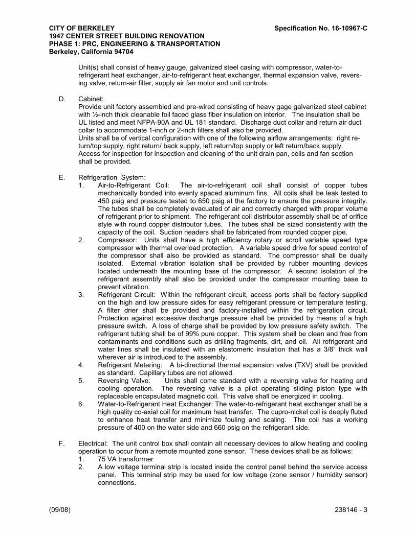
CITY OF BERKELEY Specification No. 16-10967-C 1947 CENTER STREET BUILDING RENOVATION PHASE 1: PRC, ENGINEERING & TRANSPORTATION Berkeley, California 94704
(09/08) 238146 - 3
Unit(s) shall consist of heavy gauge, galvanized steel casing with compressor, water-to-refrigerant heat exchanger, air-to-refrigerant heat exchanger, thermal expansion valve, revers-ing valve, return-air filter, supply air fan motor and unit controls.
D. Cabinet: Provide unit factory assembled and pre-wired consisting of heavy gage galvanized steel cabinet with ½-inch thick cleanable foil faced glass fiber insulation on interior. The insulation shall be UL listed and meet NFPA-90A and UL 181 standard. Discharge duct collar and return air duct collar to accommodate 1-inch or 2-inch filters shall also be provided. Units shall be of vertical configuration with one of the following airflow arrangements: right re-turn/top supply, right return/ back supply, left return/top supply or left return/back supply. Access for inspection for inspection and cleaning of the unit drain pan, coils and fan section shall be provided.
E. Refrigeration System: 1. Air-to-Refrigerant Coil: The air-to-refrigerant coil shall consist of copper tubes
mechanically bonded into evenly spaced aluminum fins. All coils shall be leak tested to 450 psig and pressure tested to 650 psig at the factory to ensure the pressure integrity. The tubes shall be completely evacuated of air and correctly charged with proper volume of refrigerant prior to shipment. The refrigerant coil distributor assembly shall be of orifice style with round copper distributor tubes. The tubes shall be sized consistently with the capacity of the coil. Suction headers shall be fabricated from rounded copper pipe.
2. Compressor: Units shall have a high efficiency rotary or scroll variable speed type compressor with thermal overload protection. A variable speed drive for speed control of the compressor shall also be provided as standard. The compressor shall be dually isolated. External vibration isolation shall be provided by rubber mounting devices located underneath the mounting base of the compressor. A second isolation of the refrigerant assembly shall also be provided under the compressor mounting base to prevent vibration.
3. Refrigerant Circuit: Within the refrigerant circuit, access ports shall be factory supplied on the high and low pressure sides for easy refrigerant pressure or temperature testing. A filter drier shall be provided and factory-installed within the refrigeration circuit. Protection against excessive discharge pressure shall be provided by means of a high pressure switch. A loss of charge shall be provided by low pressure safety switch. The refrigerant tubing shall be of 99% pure copper. This system shall be clean and free from contaminants and conditions such as drilling fragments, dirt, and oil. All refrigerant and water lines shall be insulated with an elastomeric insulation that has a 3/8” thick wall wherever air is introduced to the assembly.
4. Refrigerant Metering: A bi-directional thermal expansion valve (TXV) shall be provided as standard. Capillary tubes are not allowed.
5. Reversing Valve: Units shall come standard with a reversing valve for heating and cooling operation. The reversing valve is a pilot operating sliding piston type with replaceable encapsulated magnetic coil. This valve shall be energized in cooling.
6. Water-to-Refrigerant Heat Exchanger: The water-to-refrigerant heat exchanger shall be a high quality co-axial coil for maximum heat transfer. The cupro-nickel coil is deeply fluted to enhance heat transfer and minimize fouling and scaling. The coil has a working pressure of 400 on the water side and 660 psig on the refrigerant side.
F. Electrical: The unit control box shall contain all necessary devices to allow heating and cooling operation to occur from a remote mounted zone sensor. These devices shall be as follows: 1. 75 VA transformer 2. A low voltage terminal strip is located inside the control panel behind the service access
panel. This terminal strip may be used for low voltage (zone sensor / humidity sensor) connections.

CITY OF BERKELEY Specification No. 16-10967-C 1947 CENTER STREET BUILDING RENOVATION PHASE 1: PRC, ENGINEERING & TRANSPORTATION Berkeley, California 94704
(09/08) 238146 - 4
3. Units with 460 volt power require an additional neutral wire for installation.
G. Controls: Unit controls shall be factory-wired, factory tested, and factory-commissioned. Each WSHP unit shall be controlled by a direct digital controller with WSHP control logic for standalone control or BAS integration via the BACnet™ MS/TP protocol. Control of the variable speed compressor and supply air fan motor is shall be provided by the unit controller to optimize energy efficiency and comfort. The controller shall have the ability to control to four setpoints: occupied, occupied standby, occupied bypass and unoccupied. It shall also provide anti-short cycle compressor protection, random start delay, filter maintenance timer, timed override, isolation valve control (two position), condensate overflow protection, high and low pressure protection, diagnostics, test mode for troubleshooting.
H. Supply Air Fan and Motor Assembly: The fan shall be of forward-curved style wheel constructed of corrosion resistant galvanized material. The fan is placed in a draw-through configuration and shall be arranged for top or back supply air. This assembly shall attach the wheel and motor to the fan housing providing single side service access. The fan motor is an ECM programmable type motor. The motor shall be pre-programmed at the factory for variable air flow. Minimum and maximum airflow settings shall be configurable. The motor shall have permanently lubricated and sealed bearings and shall be protected by an internal thermal overload. Removal of the motor and fan wheel shall be made with the assistance of a factory provided orifice ring assembly. This assembly shall attach the wheel and motor to the fan housing providing single side service access.
I. Drain Pan: The drain pan shall be constructed of corrosion resistant material and insulated to prevent sweating. Acceptable materials include polymer or 304 stainless steel. Galvanized steel drain pans are not allowed. The bottom of the drain pan shall be sloped on two planes to pitch the condensate toward the drain connection to ensure complete condensate drainage when unit is installed level and trapped per manufacturer’s installation instructions. The drain pan shall comply with ASHRAE 62 for IAQ conformity. A UL508 float switch shall be factory installed on all units as standard.
J. Filters: Factory installed filters shall be of 2-inch MERV 8 as specified on the schedule.
2.4 SEQUENCE OF OPERATION
A. Occupied Mode – All unit functions will be enabled for normal heating and cooling operation. The unit shall operate to maintain the space temperature at the active occupied heating or cooling setpoint . If communication with the BAS is lost, default temperature setpoints shall be used. Setpoints shall be made by one of the following methods. 1. Remotely through BAS by the system operator 2. Locally through the zone sensor by the occupant 3. Locally through the zone sensor by the occupant within limits defined through the BAS or
system operator 4. Operator may designate wild card setpoints to apply to any or all of the WSHP’s through
the BAS.
B. Occupied Standby – The unit shall operate at heating or cooling setpoints between the occupied and unoccupied setpoints to help maintain the zone temperature while decreasing energy consumption.
C. Occupied Bypass – The unit shall transition from the unoccupied mode to the occupied mode for a period of time from 0 to 4 hours.

CITY OF BERKELEY Specification No. 16-10967-C 1947 CENTER STREET BUILDING RENOVATION PHASE 1: PRC, ENGINEERING & TRANSPORTATION Berkeley, California 94704
(09/08) 238146 - 5
D. Unoccupied Mode – The unit shall attempt to maintain the zone temperature at the stored unoccupied heating or cooling setpoint.
E. Timed Override – The unit shall transition to the Occupied Bypass mode for the selected Occupied Bypass Time if the timed override operation is enabled while the unit is in Unoccupied mode.
F. Demand Limiting Mode – The controller shall support communicated requests for demand limiting of the compressor and supply fan outputs. When demand limiting is enabled, the unit capacity shall be limited to a maximum of 50% for all unit modes. Demand Limit requests shall not override compressor startup and shutdown sequences or unit protection modes.
G. Test Mode – Two field test modes shall be supported by the controller to allow the user to troubleshoot the system. One test mode is available through a service tool and other is available through a local input on the controller.
2.5 ACCESSORIES
A. Hose Kits: Tag hose kits to equipment designations. (May use in lieu of individual components detailed on plans). 1. Minimum Working Pressure: 400 psig. 2. Operating Temperatures: From 33 to 211 deg F. 3. Minimum Hose Diameter: Equal to water-source unitary heat-pump piping connection. 4. Hose Material: Braided stainless steel with adapters for pipe connections. 5. Isolation Valves: Two-piece, bronze-body ball valves with stainless-steel ball and stem,
standard-port threaded connections, and galvanized-steel lever handle. Valves shall be factory installed on supply and return connections of both load-side and source-side heat exchangers. If balancing valve is combination shutoff type with memory stop, the isolation valve may be omitted on the return.
6. Strainer: Y-pattern with blowdown valve in supply connections of both load and source side of heat exchangers.
7. Balancing Valves: Mount in return connection. Include meter ports to allow flow measurement with differential pressure gage.
a. Automatic balancing valve, factory set to operate within 10 percent of design flow rate over a pressure range of 2 to 80 psig.
b. Manual, calibrated-orifice balancing valve with memory stop. c. Manual, venturi-type balancing valve with memory stop.
8. Water-Regulating Valve Assemblies: A direct acting valve regulates discharge pressure during the cooling cycle, and a reverse acting valve regulates the suction pressure during the heating cycle. Valves shall close when heat-pump compressor is not running.
9. Motorized Water Valve: Stop water flow through the unit when compressor is off. Slow-acting, 24-V dc valve with threaded connections is installed between isolation valves and heat exchanger.
PART 3 - EXECUTION
3.1 EXAMINATION
A. Examine areas and conditions, with Installer present, for compliance with requirements for installation tolerances and other conditions affecting performance of the Work.
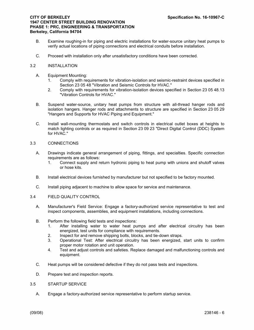
CITY OF BERKELEY Specification No. 16-10967-C 1947 CENTER STREET BUILDING RENOVATION PHASE 1: PRC, ENGINEERING & TRANSPORTATION Berkeley, California 94704
(09/08) 238146 - 6
B. Examine roughing-in for piping and electric installations for water-source unitary heat pumps to verify actual locations of piping connections and electrical conduits before installation.
C. Proceed with installation only after unsatisfactory conditions have been corrected.
3.2 INSTALLATION
A. Equipment Mounting: 1. Comply with requirements for vibration-isolation and seismic-restraint devices specified in
Section 23 05 48 "Vibration and Seismic Controls for HVAC." 2. Comply with requirements for vibration-isolation devices specified in Section 23 05 48.13
"Vibration Controls for HVAC."
B. Suspend water-source, unitary heat pumps from structure with all-thread hanger rods and isolation hangers. Hanger rods and attachments to structure are specified in Section 23 05 29 "Hangers and Supports for HVAC Piping and Equipment."
C. Install wall-mounting thermostats and switch controls in electrical outlet boxes at heights to match lighting controls or as required in Section 23 09 23 "Direct Digital Control (DDC) System for HVAC."
3.3 CONNECTIONS
A. Drawings indicate general arrangement of piping, fittings, and specialties. Specific connection requirements are as follows: 1. Connect supply and return hydronic piping to heat pump with unions and shutoff valves
or hose kits.
B. Install electrical devices furnished by manufacturer but not specified to be factory mounted.
C. Install piping adjacent to machine to allow space for service and maintenance.
3.4 FIELD QUALITY CONTROL
A. Manufacturer's Field Service: Engage a factory-authorized service representative to test and inspect components, assemblies, and equipment installations, including connections.
B. Perform the following field tests and inspections: 1. After installing water to water heat pumps and after electrical circuitry has been
energized, test units for compliance with requirements. 2. Inspect for and remove shipping bolts, blocks, and tie-down straps. 3. Operational Test: After electrical circuitry has been energized, start units to confirm
proper motor rotation and unit operation. 4. Test and adjust controls and safeties. Replace damaged and malfunctioning controls and
equipment.
C. Heat pumps will be considered defective if they do not pass tests and inspections.
D. Prepare test and inspection reports.
3.5 STARTUP SERVICE
A. Engage a factory-authorized service representative to perform startup service.

CITY OF BERKELEY Specification No. 16-10967-C 1947 CENTER STREET BUILDING RENOVATION PHASE 1: PRC, ENGINEERING & TRANSPORTATION Berkeley, California 94704
(09/08) 238146 - 7
1. Complete installation and startup checks according to manufacturer's written instructions. 2. Inspect for visible damage to unit casing. 3. Inspect for visible damage to compressor and coils. 4. Inspect internal insulation. 5. Verify that labels are clearly visible. 6. Verify that clearances have been provided for servicing. 7. Verify that controls are connected and operable. 8. Adjust vibration isolators. 9. Start unit according to manufacturer's written instructions. 10. Complete startup sheets and attach copy with Contractor's startup report. 11. Inspect and record performance of interlocks and protective devices; verify sequences. 12. Operate unit for an initial period as recommended or required by manufacturer. 13. Verify thermostat calibration.
B. Inspect controls for correct sequencing of heating, refrigeration, and normal and emergency shutdown. Engage an OEM factory technician to setup BACnet controls. Provide up to four (4) additional site visits (32 hours min.) during construction to coordination controls and provide on-site assistance to the building controls (Alerton) in adjusting controls to suit the desired occupied conditions and sequence of operations. 1. Set the BACnet MS/TP network address for each heat pump. 2. Configure controller for each heat pump:
a. Set controller name (based on WSHP tag number). b. Set preferred units of measure for data communicated across the BACnet link. c. Set preferred baud rate. d. Set BACnet device ID.
3. Set Media Access Control (MAC) address for each heat pump. 4. Trane shall provide the controls contractor and the owner with one copy of the Tracer TU
configuration tool.
3.6 ADJUSTING
A. Adjust initial temperature set points.
B. Set field-adjustable switches and circuit-breaker trip ranges as indicated.
C. Occupancy Adjustments: When requested within 12 months from date of Substantial Completion, provide on-site assistance in adjusting system to suit actual occupied conditions. Provide up to three (3) visits to Project during other-than-normal occupancy hours for this purpose.
3.7 DEMONSTRATION
Train Owner's maintenance personnel to adjust, operate, and maintain water-source unitary heat pumps.
3.8 COMMISSIONING SUPPORT
A. Equipment manufacturer shall provide OEM technician field support for testing of controls sequence and commissioning.
END OF SECTION

CITY OF BERKELEY Specification No. 16-10967-C1947 CENTER STREET BUILDING RENOVATIONPHASE 1: PRC, ENGINEERING & TRANSPORTATIONBerkeley, CA 94704
BASIC ELECTRICAL REQUIREMENTS(09-08) 26 05 00 - 1
SECTION 26 05 00BASIC ELECTRICAL REQUIREMENTS
PART 1 - GENERAL
1.1 WORK INCLUDED
A. Work included in this Section: All materials, labor, equipment, services, and incidentalsnecessary to install the Electrical Work as shown on the drawings and as specified hereinafter,including, but not limited to the following:1. Branch circuit wiring, wiring devices and connections to all equipment requiring
electrical service.2. Lighting fixtures completely lamped, including switches, raceways and wiring.3. Emergency egress/exit illumination system.4. Telecommunications system.5. Fire Alarm system.6. Mechanical equipment power connections, and motor starters where noted.7. Low voltage lighting control system and programming.8. All required incidental work, such as electrical testing, title 24 acceptance testing, and
temporary power.9. Any other electrical work as might reasonably be implied as required, even though not
specifically mentioned herein or shown on the drawings.10. It is the intent of the drawings and specifications that systems be complete and, except as
otherwise noted, be ready for operation.
1.2 RELATED WORK
A. Division 1 - General Requirements
B. Division 9 - Finishes
C. Division 23 - Mechanical
D. Section 07270 - Firestopping
1.3 INCORPORATED DOCUMENTS
A. Requirements of the General Conditions, Supplementary Conditions, and Division 1 Sectionsapply to all work in this Section, unless modified herein.
B. Published specifications, standard tests or recommended methods of trade, industry orgovernment organizations apply to work of this Section where cited by abbreviations notedbelow, unless modified herein.1. 2013 California Code of Regulations.2. 2013 California Building Standards Administrative Code, Part 1, Title 24, C.C.R.

CITY OF BERKELEY Specification No. 16-10967-C1947 CENTER STREET BUILDING RENOVATIONPHASE 1: PRC, ENGINEERING & TRANSPORTATIONBerkeley, CA 94704
BASIC ELECTRICAL REQUIREMENTS(09-08) 26 05 00 - 2
3. 2013 California Building Code (CBC), Part 2, Title 24, C.C.R. (Based on 2012International Building Code with 2013 California Amendments).
4. 2013 California Electrical Code (CEC), Part 3, Title 24, C.C.R. (Based on 2011 NationalElectrical Code with 2013 California Amendments).
5. California Energy Code, Part 6, Title 24, C.C.R.6. 2013 California Fire Code (CFC), Part 9, Title 24, C.C.R. (Based on 2012 International
Fire Code with 2013 California Amendments).7. 2013 California Green Building Standards (CALGreen) Code, Part 11.8. American Society of Civil Engineers 7-10 (ASCE/SEI), Minimum Design Loads for
Buildings and Other Structures.9. Underwriters' Laboratories, Inc. (UL).
C. All State and Municipal Codes and Ordinances.
1.4 CONDITIONS AT SITE:
A. Visit to site is required of all bidders prior to submission of bid. All will be held to havefamiliarized themselves with all discernible conditions and no extra payment will be allowedfor work required because of these conditions, whether specifically mentioned or not.
B. Lines of other services that are damaged as a result of this work shall promptly be repaired atno expense to the Owner to the complete satisfaction of the Owner.
1.5 QUALITY ASSURANCE
A. Conformance:1. All work shall conform to the applicable requirements of Article 1.3 above.2. The Contractor shall notify the Architect, prior to submission of bid, about any part of the
design, which fails to comply with abovementioned requirements.3. If after contract is awarded, minor changes and additions are required by aforementioned
authorities, even though such work is not shown on drawings or covered in thespecifications, they shall be included at Contractor's expense.
B. Coordination:1. The Contractor shall become familiar with the conditions at the job site, and with the
drawings and specifications and plan the installation of the electrical work to conformwith the existing conditions and that shown and specified so as to provide the bestpossible assembly of the combined work of all trades.
2. The Contractor shall work out in advance all "tight" conditions, involving all trades and iffound necessary, supplementary drawings shall be prepared by this Contractor, for theArchitect's approval, before work proceeds in these areas. No additional costs will beconsidered for work, which must be relocated due to conflicts with the work of othertrades.
3. The Contractor shall coordinate and verify all backbox, device, lighting fixture, orequipment mounting requirements with the devices or equipment to be installed, prior torough in.
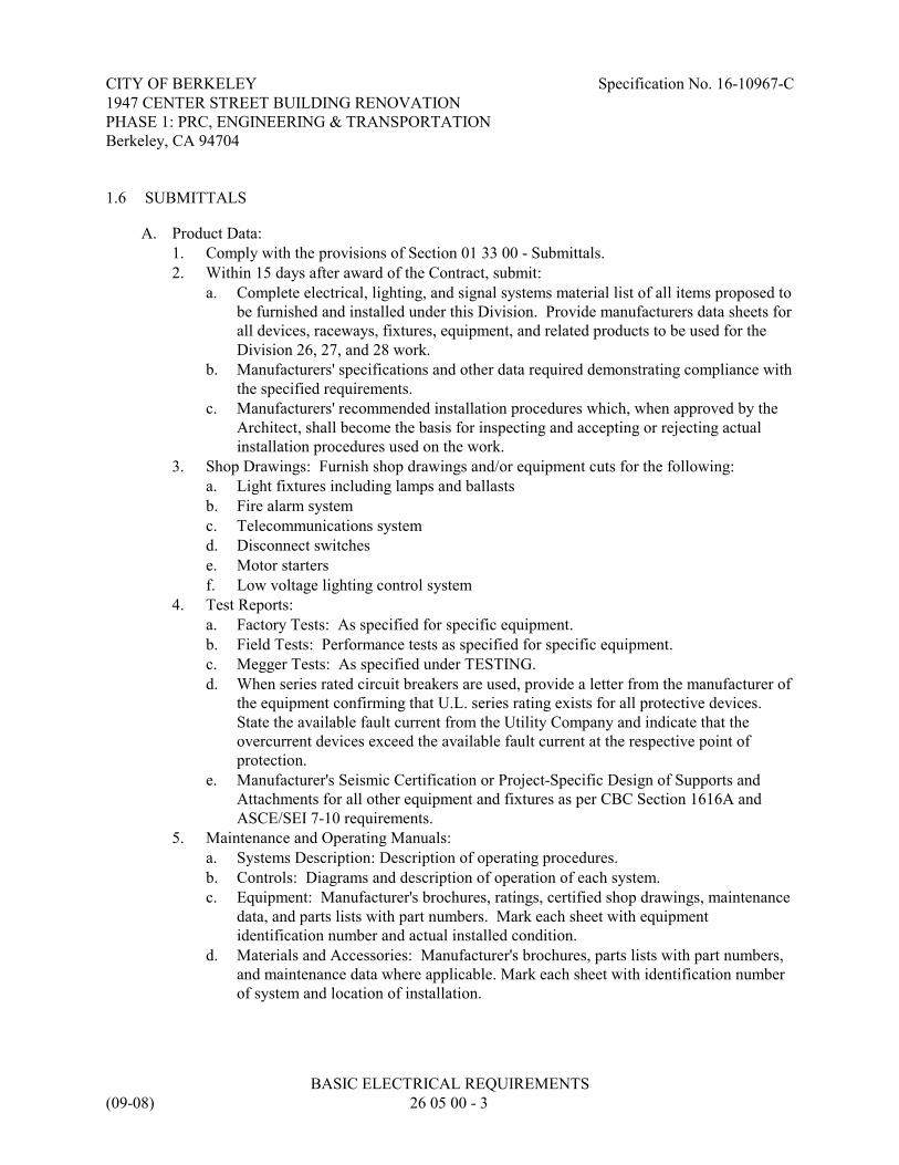
CITY OF BERKELEY Specification No. 16-10967-C1947 CENTER STREET BUILDING RENOVATIONPHASE 1: PRC, ENGINEERING & TRANSPORTATIONBerkeley, CA 94704
BASIC ELECTRICAL REQUIREMENTS(09-08) 26 05 00 - 3
1.6 SUBMITTALS
A. Product Data:1. Comply with the provisions of Section 01 33 00 - Submittals.2. Within 15 days after award of the Contract, submit:
a. Complete electrical, lighting, and signal systems material list of all items proposed tobe furnished and installed under this Division. Provide manufacturers data sheets forall devices, raceways, fixtures, equipment, and related products to be used for theDivision 26, 27, and 28 work.
b. Manufacturers' specifications and other data required demonstrating compliance withthe specified requirements.
c. Manufacturers' recommended installation procedures which, when approved by theArchitect, shall become the basis for inspecting and accepting or rejecting actualinstallation procedures used on the work.
3. Shop Drawings: Furnish shop drawings and/or equipment cuts for the following:a. Light fixtures including lamps and ballastsb. Fire alarm systemc. Telecommunications systemd. Disconnect switchese. Motor startersf. Low voltage lighting control system
4. Test Reports:a. Factory Tests: As specified for specific equipment.b. Field Tests: Performance tests as specified for specific equipment.c. Megger Tests: As specified under TESTING.d. When series rated circuit breakers are used, provide a letter from the manufacturer of
the equipment confirming that U.L. series rating exists for all protective devices.State the available fault current from the Utility Company and indicate that theovercurrent devices exceed the available fault current at the respective point ofprotection.
e. Manufacturer's Seismic Certification or Project-Specific Design of Supports andAttachments for all other equipment and fixtures as per CBC Section 1616A andASCE/SEI 7-10 requirements.
5. Maintenance and Operating Manuals:a. Systems Description: Description of operating procedures.b. Controls: Diagrams and description of operation of each system.c. Equipment: Manufacturer's brochures, ratings, certified shop drawings, maintenance
data, and parts lists with part numbers. Mark each sheet with equipmentidentification number and actual installed condition.
d. Materials and Accessories: Manufacturer's brochures, parts lists with part numbers,and maintenance data where applicable. Mark each sheet with identification numberof system and location of installation.

CITY OF BERKELEY Specification No. 16-10967-C1947 CENTER STREET BUILDING RENOVATIONPHASE 1: PRC, ENGINEERING & TRANSPORTATIONBerkeley, CA 94704
BASIC ELECTRICAL REQUIREMENTS(09-08) 26 05 00 - 4
e. The Maintenance and Operation Manual shall be presented in a three ring binder thathas tabbed sections as stated below. Provide all information in each section as statedbelow.1) 26 5101:
(a) Insert the approved submittals for the light fixtures.(b) Highlight the lamp type that was installed for each light fixture.(c) Provide the names, address and telephone numbers of the manufacturer and
the closest manufacturer's representative for each light fixture.2) 26 5101:
(a) Insert the approved submittals for the motion sensing light controlequipment.
(b) Insert all operating instructions.(c) Provide the names, address and telephone number of the manufacturer and
the closest manufacturer's representative of the equipment.(d) Include the manufacturer's recommended maintenance of the equipment.
3) 26 5700:(a) Insert the approved submittals for the low voltage lighting control
equipment.(b) Insert all operating instructions.(c) Provide the names, address and telephone number of the manufacturer and
the closest manufacturer's representative of the equipment.(d) Include the manufacturer's recommended maintenance of the equipment.
4) 27 0000:(a) Insert the approved submittals for the telephone/data system.(b) Provide the names, address and telephone number of the manufacturer and
the closest manufacturer's representative of the equipment.(c) Include the manufacturer's recommended maintenance of the equipment.
5) 28 3101:(a) Complete the “Record Of Completion” entirely.(b) In the “Download File” indicate the exact equipment that the Monitor
Modules are monitoring. i.e. fire sprinkler flow switches, tamper switches,etc..
(c) Simplify the Download File so that it coincides with the submitted andapproved fire alarm single line diagram.
(d) Provide the names, address and telephone number of the manufacturer andthe closest manufacturer's representative of the equipment.
(e) Include the manufacturer's recommended maintenance of the equipment.(f) Insert an abbreviated data sheet that states how to test, reset and silence the
fire alarm system.(g) Insert the name and telephone number of the Central Station that receives
the alarms, and the proper sequence to follow during an alarm.6) 26 0800:
(a) Insert all feeder and data system testing results.6. Record Documents: "As-builts": As specified under Paragraph 3.2 of this Section.

CITY OF BERKELEY Specification No. 16-10967-C1947 CENTER STREET BUILDING RENOVATIONPHASE 1: PRC, ENGINEERING & TRANSPORTATIONBerkeley, CA 94704
BASIC ELECTRICAL REQUIREMENTS(09-08) 26 05 00 - 5
1.7 DELIVERY, STORAGE AND HANDLING
A. Protection: Use all means necessary to protect the materials of this Section before, during, andafter installation and to protect the work and materials of all trades.
B. Delivery and Storage: Deliver all materials to the job site in their original containers with alllabels intact and legible at time of use. Store in strict accordance with approved manufacturers'recommendations.
C. Replacements: In the event of damage, immediately make all repairs and replacementsnecessary to the approval of the Architect and at no additional cost to the Owner.
D. This Contractor shall personally, or through an authorized representative, check all materialsupon receipt at jobsite for conformance with approved shop drawings and/or plans andspecifications.
1.8 SCHEDULING/SEQUENCING
A. Place orders for all equipment in time to prevent any delay in construction schedule orcompletion of project. If any materials or equipment are not ordered in time, additionalcharges made by equipment manufacturers to complete their equipment in time to meet theconstruction schedule, together with any special handling charges, shall be borne by thisContractor.
B. The Contractor shall coordinate production and delivery schedule for all Owner-suppliedequipment with the equipment suppliers to ensure that all Owner-supplied equipment isdelivered to site in coordination with the construction schedule and in such a manner as tocause no delays in completion of the Contract as scheduled.
1.9 REQUIREMENTS
A. The contract drawings indicate the extent and general arrangements of the conduit wiringsystems, etc. If any departures from the contract drawings are deemed necessary by theContractor, details of such departures and the reasons therefore shall be submitted as soon aspracticable, and within thirty-five (35) days after award of the electrical contract.
B. Unless material list and data is received as a complete and all inclusive submittal within thestipulated time all items shall be provided as specified, with no deviations permitted.
C. Any and all additional costs incurred by the substitution of electrical material or equipment, orinstallation thereof, whether architectural, structural, plumbing, mechanical or electrical, shallbe borne by the Contractor under this Section.
D. Burden of proof of equality of any substitution for a specified product is the responsibility ofthis Contractor.

CITY OF BERKELEY Specification No. 16-10967-C1947 CENTER STREET BUILDING RENOVATIONPHASE 1: PRC, ENGINEERING & TRANSPORTATIONBerkeley, CA 94704
BASIC ELECTRICAL REQUIREMENTS(09-08) 26 05 00 - 6
E. Where required by Architect to ascertain equality of substitute product, Contractor may berequested to provide the specified item and the submitted substitution for comparison, at noadditional cost to the Owner.
1.10 DESCRIPTION OF WORK
A. This project involves renovation in an existing and functioning building. As such, the projectscope for this contractor will include all associated electrical, lighting, and signal systemupgrades and demolition/removal work at the areas of work. The intent is that all systems willbe complete and functional at the completion of this contract and that all old systems,equipment, feeders, circuits, wiring, and related devices (no longer used), in the areas of work,be completely and neatly removed. Where discrepancies between the drawings and existingconditions are noted, the project manager shall be notified immediately for resolution.
B. As with every renovation project, the electrical work will include (and require) exploration andother field work on a daily basis to complete the new designed equipment and connectionswithin the constraints of the existing building and existing site conditions.
C. The contractor shall include as part of the base bid, sufficient labor hours to provide suchexploration and field work throughout the duration of the project. Change orders for misc.coordination of existing conditions will not be approved unless specific and latent conditionsare uncovered that warrant such additional compensation or require additional work not shownon the plans or implied by the designed conditions.
D. New raceways and wiring to new and renovated equipment are to be installed unless otherwisenoted. Where raceways are installed in accessible concealed locations (i.e. unfinished spacesor electrical / mechanical / attic spaces), EMT with wire shall be used. Where new wiring isrequired to be routed through existing walls and ceilings that can not easilly be accessible fornew conduit, MC cable or flex conduit and wiring may be installed, fished through and securedin each space as required by code. Non-metallic sheathed cable shall not be utilized on thisproject.
E. All new raceways shall be installed concealed and all new equipment installed flush, unlessotherwise noted on the plans or in these specifications.
1.11 GUARANTEE
A. This Contractor shall guarantee that all work executed under this Section will be free fromdefects of materials and workmanship for a period of one (1) year or as per the GeneralConditions of this project, whichever is longer. Dates shall be from the date of finalacceptance of the building. The contractor shall further guarantee that he will, at his ownexpense, repair and replace all such defective work, and all other work damaged thereby,which becomes defective during the term of the guarantee. Such repair or replacement shall beguaranteed for one (1) year from the date of repair or replacement.

CITY OF BERKELEY Specification No. 16-10967-C1947 CENTER STREET BUILDING RENOVATIONPHASE 1: PRC, ENGINEERING & TRANSPORTATIONBerkeley, CA 94704
BASIC ELECTRICAL REQUIREMENTS(09-08) 26 05 00 - 7
1.12 PERMITS AND INSPECTIONS
A. This Contractor shall arrange for and obtain all required inspections.
B. The Contractor sjhall pay for all required permits and inspections.
C. Do not allow or cause any of the work to be covered or enclosed until it has been tested and/orinspected.
1.13 IDENTIFICATION
A. Switchboards, feeder circuit breakers in switchboards, panels, disconnect switches, motorstarters, transformers, motor disconnect switches, cabinets, and other apparatus used for theoperation of, or control of circuits, appliances or equipment, shall be properly identified bymeans of engraved laminated plastic descriptive nameplates mounted on apparatus usingstainless steel screws. Nameplates shall have white letters with black background and besubmitted to the Architect for approval. Cardholders in any form are not acceptable.
B. Provide p-touch style labeling of circuit designations for all receptacles on the project.
C. Each branch circuit of panel boards to have a permanently fixed number with load directory,mounted under celluloid on inside of cabinet door, showing circuit numbers and typewrittendescription of equipment supplied by breakers.
D. Provide label on all motors: "Caution. Automatic equipment. May start at any time."
E. Provide silk-screened or engraved identification labels on all switch box covers identifyingspecific loads that are not readily apparent to the user, including electroshades, projectionscreens, exhaust fans, etc.. Submit proposed labels to Architect for approval prior tomanufacture of labels.
PART 2 - PRODUCTS
2.1 GENERAL
A. Refer to applicable Division 26, 27, and 28 Sections for complete products specifications.
2.2 MATERIALS
A. Materials of the same type or classification, used for the same purpose, shall be the product ofthe same manufacturer.
2.3 ACCEPTABLE MANUFACTURERS
A. Materials shall be of make mentioned elsewhere in this specification. All materials shall be thebest of their several kinds, perfectly new and approved by the Underwriters' Laboratories.

CITY OF BERKELEY Specification No. 16-10967-C1947 CENTER STREET BUILDING RENOVATIONPHASE 1: PRC, ENGINEERING & TRANSPORTATIONBerkeley, CA 94704
BASIC ELECTRICAL REQUIREMENTS(09-08) 26 05 00 - 8
B. Where material, equipment, apparatus or other products are specified by manufacturer, brandname, type or catalog number, such designation is to establish standards of desired quality,style and utility and shall be the basis of the bid. Materials so specified shall be furnishedunder the contract unless changed by written approval of the Architect. Where two or moredesignations are listed, choice shall be optional with this Contractor, but this Contractor mustsubmit his choice for final approval.
2.4 POSTED OPERATING INSTRUCTIONS
A. Furnish approved operating instructions for systems and equipment where indicated in thetechnical sections for use by operation and maintenance personnel. The operating instructionsshall include wiring diagrams, control diagrams, and control sequence for each principalsystem and equipment. Print or engrave operating instructions and frame under glass or inapproved laminated plastic. Post instructions as directed. Attach or post operating instructionsadjacent to each principal system and equipment including startup, proper adjustment,operating, lubrication, shutdown, safety precautions, procedure in the event of equipmentfailure, and other items of instruction as recommended by the manufacturer of each system orequipment. Provide weather-resistant materials or weatherproof enclosures for operatinginstruction exposed to the weather. Operating instruction shall not fade when exposed tosunlight and shall be secured to prevent easy removal or peeling.
2.5 CATALOGED PRODUCTS/SERVICE AVAILABILITY
A. Materials and equipment shall be current products by manufacturers regularly engaged in theproduction of such products. Products shall have been in satisfactory commercial or industrialuse for 2 years prior to bid opening. The 2-year period shall include applications of equipmentand materials under similar circumstances and of similar size. The 2-year period shall besatisfactorily completed by a product for sale on the commercial market throughadvertisements, manufacturers' catalogs, or brochures. Products having less than a 2-year fieldservice record will be acceptable if a certified record of satisfactory field operation for not lessthan 6,000 hours, exclusive of the manufacturers' factory or laboratory tests, is furnished. Theequipment items shall be supported by service organizations which are reasonable convenientto the equipment installation in order to render satisfactory service to the equipment on aregular and emergency basis during the warranty period of the contract.
PART 3 - EXECUTION
3.1 INSPECTION
A. Examine the areas and conditions under which the work of this Section will be installed. Correct conditions detrimental to the proper and timely completion of the Work. Do notproceed until unsatisfactory conditions have been corrected.
3.2 PREPARATION
A. Drawings:

CITY OF BERKELEY Specification No. 16-10967-C1947 CENTER STREET BUILDING RENOVATIONPHASE 1: PRC, ENGINEERING & TRANSPORTATIONBerkeley, CA 94704
BASIC ELECTRICAL REQUIREMENTS(09-08) 26 05 00 - 9
1. The general arrangement and location of wiring and equipment is shown on the electricaldrawings and shall be installed in accordance therewith, except for minor changesrequired by conflict with the work of other trades.
2. The Contractor shall coordinate and verify all backbox, device, lighting fixture, orequipment mounting requirements with the devices or equipment to be installed, prior torough in.
3. Drawings indicate the circuit and panel which supplies each device or fixture. Provideand install conduit and conductors to make all connections from panel to nearest deviceand from first device to additional devices on same circuit. Conduit size and fill shallsatisfy NEC requirements. Two or three different phases supplied by a 3-phase panel mayshare a single neutral only if circuit positions are adjacent in the panel. Do not exceed 4#12 or 3 #10 conductors in a ½" conduit, 7 #12 or 5 #10 in a 3/4" conduit, and 11 #12 or 9#10 in a 1" conduit, unless otherwise noted. Provide common handle-tie on breakers formulti-wire branch circuits (with common neutral), per NEC. If more than three currentcarrying conductors are installed in one conduit, conductor size shall be increased asrequired per NEC. Do not share neutrals for branch circuit runs to electronic equipmentor where noted on the drawings.
4. Drawings indicate the location of all light switches. Where fixtures in a room arecontrolled by more than one switch, the same lower case letter is drawn adjacent to aswitch and each fixture controlled by that switch. Where no lower case letter is adjacentto a switch, all fixtures in the room are controlled by that switch. Provide and installconduit and wire from fixture to switch and between fixtures as required to accomplishswitching shown. Do not route branch circuit wiring for light fixtures through switchboxes.
5. Drawings indicate location of all signal outlet boxes. Provide and install conduit systemas required as required and complete system wiring, unless otherwise noted.
6. Control wiring is generally not shown on the plans. Contractor shall refer to controldiagrams and provide and install all wiring and raceways required to make allinterconnections.
7. All branch circuit wiring No. 12 or No. 10 as noted, all control wiring No. 14, except asnoted next to "slash marks" on drawings, or as noted under "Wire," as specified herein.
8. All dimensions, together with locations of doors, partitions, etc. are to be taken from theArchitectural Drawings, verified at site by this Contractor.
9. Maintain "as-built" records at all times, showing the exact location of concealed conduitsand feeders installed under this contract, and actual numbering of each circuit. Uponcompletion of work and before acceptance can be considered, this Contractor mustforward to Architect vellums (obtained from the Architect at cost) corrected to show theelectrical work as installed.
10. Branch circuit conductors shall be #12 minimum and #10 minimum for runs longer than150 feet.
B. Measurements: Before ordering any material or closing in any work, verify all measurementson the job. Any differences found between dimensions on the drawings and actualmeasurements shall be brought to the Architect's attention for consideration before proceeding.

CITY OF BERKELEY Specification No. 16-10967-C1947 CENTER STREET BUILDING RENOVATIONPHASE 1: PRC, ENGINEERING & TRANSPORTATIONBerkeley, CA 94704
BASIC ELECTRICAL REQUIREMENTS(09-08) 26 05 00 - 10
3.3 FIELD QUALITY CONTROL
A. All workmanship shall be first class and carried out in a manner satisfactory to and approvedby the Architect.
B. This Contractor shall personally, or through an authorized and competent representative,constantly supervise the work and so far as possible keep the same foreman and workmen onthe job throughout.
3.4 INSTALLATION/APPLICATION/ERECTION
A. All electrical raceways and devices shall be installed concealed (for raceways) and/or flushmounted (for devices), unless otherwise noted. Provide cut-in boxes and "fish" flexible MC orflex conduit and wire through existing walls to remain, unless shown otherwise on plans. Cutand patch to facilitate such installation to match adjacent and original finish.
B. All cutting, repairing and structural reinforcing for the installation of this work shall be doneby the General Contractor in conformance with the Architect's requirements.
3.5 TEMPORARY LIGHTING AND POWER
A. Provide and install temporary lighting and power systems for the duration of construction, ofadequate size to accommodate the required lighting and power loads. Coordinate with othertrades to insure adequate sizing.
B. Provide distribution equipment as required to support all construction activities.
3.6 FIRE STOPPING AND FIRE RATED PENETRATIONS
A. All electrical equipment mounted in, on, or through fire rated construction shall be installed tomaintain the fire rating of the construction.
B. Provide fire rated pads (or other suitable assembly) around all electrical junction boxes in firerated walls/ceilings/floors to maintain the fire rating.
C. Provide fire rated construction around all recessed light fixtures and/or panel board / cabinetsmounted flush in fire rated walls to maintain the fire rating. Coordinate depth of constructionwith other trades to avoid conflicts.
D. Conduit sleeves shall be provided as a means of routing cables through fire-rated walls orfloors. Openings in sleeves and conduits used for system cables and those which remain(empty) spare shall be sealed with an approved fireproof, removable sagging material. Sleeveswhich pass vertically from floor to floor shall be sealed in a similar manner using an approvedre-enterable system. Additional penetrations through rated assemblies necessary for passage oftel/data wiring shall be made using an approved method and permanently sealed afterinstallation of cables.

CITY OF BERKELEY Specification No. 16-10967-C1947 CENTER STREET BUILDING RENOVATIONPHASE 1: PRC, ENGINEERING & TRANSPORTATIONBerkeley, CA 94704
BASIC ELECTRICAL REQUIREMENTS(09-08) 26 05 00 - 11
3.7 ADJUSTING AND CLEANING
A. All electrical equipment, including existing equipment not "finish painted" under othersections, shall be touched up where finished surface is marred or damaged.
B. All equipment, lighting fixtures, etc., shall be left in clean condition, with all shipping andotherwise unnecessary labels removed there from.
3.8 SCHEDULES
A. Coordination: Coordinate installation of electrical items with the schedule for other work toprevent unnecessary delays in the total Work.
3.9 WARNING SIGN MOUNTING
A. Provide the number of signs required to be readable from each accessible side, but space thesigns a maximum of 30 feet apart.
3.10 PAINTING OF EQUIPMENT
A. Factory Applied: Electrical equipment shall have factory-applied painting systems which shall,as a minimum, meet the requirements of NEMA ICS 6 corrosion-resistance test, exceptequipment specified to meet requirements of ANSI C37.20 shall have a finish as specified inANSI C37.20.
B. Field Applied: Paint electrical equipment as required to match finish or meet safety criteria. Painting shall be as specified in the respective equipment section.
3.11 TESTS
A. Testing and inspection: See Section 26 08 00 - Testing.END OF SECTION

CITY OF BERKELEY Specification No. 16-10967-C1947 CENTER STREET BUILDING RENOVATIONPHASE 1: PRC, ENGINEERING & TRANSPORTATIONBerkeley, CA 94704
TESTING(09-08) 26 08 00 - 1
SECTION 26 08 00TESTING
PART 1 - GENERAL
1.1 WORK INCLUDED
A. Work Included in This Section: All materials, labor, equipment, services, and incidentalsnecessary to perform the testing and inspection of the electrical work, including but not limitedto the general systems noted below:1. Grounding System.2. Lighting System.3. Distribution System.4. Fire Alarm System.5. Low voltage lighting control system6. Telephone and Data Wiring Systems7. Title 24 Acceptance Testing
B. Any other electrical work as might reasonably be implied as required, even though notspecifically mentioned herein or shown on the drawings.
C. All work shall comply with Sections 26 05 00 and 26 27 00.
D. In addition to the general system tests and inspections indicated above, the Contractor shallperform the following specific tests and inspections with certified and calibrated testingequipment:1. System Grounding2. Switchgear3. Feeders
E. The purpose of these tests is to assure that all tested electrical equipment is operational andwithin industry and manufacturer's tolerances and is installed in accordance with designspecifications.
1.2 APPLICABLE CODES, STANDARDS, AND REFERENCES
A. All inspections and tests shall be in accordance with the International Electrical TestingAssociation - Acceptance Testing Specifications ATS-2009 (referred to herein as NETAATS-2009).
1.3 QUALIFICATIONS
A. Qualifications of the Contractor shall be as listed in NETA ATS-2009.

CITY OF BERKELEY Specification No. 16-10967-C1947 CENTER STREET BUILDING RENOVATIONPHASE 1: PRC, ENGINEERING & TRANSPORTATIONBerkeley, CA 94704
TESTING(09-08) 26 08 00 - 2
PART 2 - PRODUCTS
2.1 THIS ARTICLE DOES NOT APPLY TO TESTING.
PART 3 - EXECUTION
3.1 GENERAL
A. Final test and inspection to be conducted in presence of the Authority having Jurisdiction (AHJ) or Inspector of Record (IOR). Test shall be conducted at the expense of, and managedby, the Contractor, at a mutually agreed time. Submit written test report of all tests, with testresult values and overall outcome.
B. All portions of the electrical installation shall be inspected and tested to ensure safety tobuilding occupants, operating personnel, conformity to code authorities and ContractDocuments, and for proper system operation.
3.2 INSPECTIONS AND TESTS
A. Tests: Field tests shall be performed and reports submitted, as per Section 26 05 00, Part 1.1. Final Inspection Certificates: Prior to final payment approval, deliver to the Owner, with
a copy to the Architect, signed certificates of final inspection by the appropriate localauthority having jurisdiction.
B. Grounding System:1. All ground connections shall be checked and the entire system shall be checked for
continuity.2. Ground tests shall meet the requirements of the National Electric Code.
C. Lighting Systems:1. The new lighting systems shall be checked for proper local controls and operation of
entire installation, including the operation of the low voltage lighting control system.
D. Power Distribution System:1. Test panel boards for grounds and shorts with mains disconnected from feeders, branch
circuits connected and circuit breakers closed, all fixtures in place and permanentlyconnected and grounding jumper to neutral lifted and with all wall switches closed.
2. Test each individual circuit at each panelboard with equipment connected for properoperation. Inspect the interior of each panel.
3. Check verification of color coding, tagging, numbering, and splice make-up.4. Verify that all conductors associated with each circuit are in same conduit.5. Demonstrate that all lights, jacks, switches, outlets, and equipment operate satisfactorily
and as called for.6. Perform megger tests of all new distribution system feeders (where applicable) prior to
energizing. All Cables failing megger tests or with evidence of damage shall be removed

CITY OF BERKELEY Specification No. 16-10967-C1947 CENTER STREET BUILDING RENOVATIONPHASE 1: PRC, ENGINEERING & TRANSPORTATIONBerkeley, CA 94704
TESTING(09-08) 26 08 00 - 3
and replaced in their entirety (no splices), at no cost to the Owner. Damaged cables maynot be field repaired without specific approval of the Architect.
E. Fire Alarm System: Verify that all equipment, components, and devices function as specified. Refer to Section 28 3101 for additional testing requirements.
F. Low Voltage Lighting Control System: Verify that all equipment, components, and devicesfunction as specified. Refer to Section 26 5101 for additional testing requirements.
G. Telephone and Data Wiring Systems: Verify that all equipment, components, and devicesfunction as specified. Refer to Section 27 0000 for additional testing requirements.
H. Title 24 Acceptance Testing: Contractor shall complete the requirements for Title 24Acceptance Testing, as per CA Title 24, Part 6.1. Perform testing requirements as per Title 24 Lighting Acceptance requirements. Testing
shall include construction inspection of installed controls, occupancy / motion sensortesting, manual daylighting controls testing, automatic time switch controls testing, anddemand response system interface, as applicable.
2. Complete and submit all required forms for complete Acceptance Testing.3. Obtain required review and approval of Acceptance Forms to allow final certificate of
occupancy to be granted.END OF SECTION

CITY OF BERKELEY Specification No. 16-10967-C1947 CENTER STREET BUILDING RENOVATIONPHASE 1: PRC, ENGINEERING & TRANSPORTATIONBerkeley, CA 94704
BASIC ELECTRICAL MATERIALS AND METHODS(09-08) 26 27 00 - 1
SECTION 26 27 00BASIC ELECTRICAL MATERIALS AND METHODS
PART 1 - GENERAL
1.1 WORK INCLUDED
A. Work included in this Section: All materials, labor, equipment, services, and incidentalsnecessary to install the electrical work as shown on the drawings and as specified hereinafter,including but not limited to the work listed below:1. Raceways, feeders, branch circuit wiring, wiring devices, safety switches and connections
to all equipment requiring electric service.
B. Any other electrical work as might reasonably be implied as required, even though notspecifically mentioned herein or shown on the drawings.
C. All work shall comply with Section 26 05 00.
1.2 RELATED WORK
A. Division 09 - Finishes
B. Division 23 - Motors and Mechanical Equipment Installation
1.3 SUBMITTALS
A. Comply with the provisions of Section 26 05 00.
PART 2 - PRODUCTS
2.1 ACCEPTABLE MANUFACTURERS
A. Refer to Section 26 05 00, Basic Electrical Requirements, Part 2 - Products.
B. List of Equipment Manufacturers:
Conduit and Conduit Fittings
Allied Tube and Conduit, Wester Tube and Conduit, LTV Steel Tubular, National ElectricProducts, AFC, Republic Steel Corporation, Rome Cable Corporation, United States SteelCorporation, Killark Electric Manufacting Company, Raco, VAW Aluminum Company,Bridgeport, Steel City, Thomas & Betts, Carlon, O.Z. Gedney, Appleton, Regal.

CITY OF BERKELEY Specification No. 16-10967-C1947 CENTER STREET BUILDING RENOVATIONPHASE 1: PRC, ENGINEERING & TRANSPORTATIONBerkeley, CA 94704
BASIC ELECTRICAL MATERIALS AND METHODS(09-08) 26 27 00 - 2
Wire and Cable (600V)
American Wire Company, General Wire and Cable Corporation, Okonite Company, RomeCable Corporation, Cerrowire, American Insulated Wire, AFC Cable Systems, Essex, SimplexWire and Cable Company, Southwire.
Solderless Lugs and Grounding Connections
Burndy Engineering Company Inc, O.Z. Gedney Company Inc, Penn Union ElectricCorporation, Thomas and Betts Company Inc.
Pull Boxes, Gutters, Special Cabinets
Square D Company, Columbia Electric Manufacturing Company, General Electric Company,Westinghouse Electric Corporation, Circle Awalt.
Outlet Boxes
Appleton Electric Company, Killark Electric Manufacturing Company, Lew Electric FittingsCompany, National Electric Products Corporation, Raco, Steel City Electric Company, Carlon,Bowers.
Wiring Devices
Leviton, Arrow-Hart, Cooper, Hubbell, Lutron, Bryant.
Conduit Racks, Hangers
General Electric Company, Killark Electric Manufacturing Company, Caddy, National ElectricProducts Corporation, Republic Steel Corporation, Rome Cable Corporation, United StatesSteel Corporation, VAW Aluminum Company, Superstrut, B-Line.
Safety Switches (Disconnect and Fusible)
Square D Company, Cutler Hammer Inc, General Electric Company, Westinghouse ElectricCorporation.

CITY OF BERKELEY Specification No. 16-10967-C1947 CENTER STREET BUILDING RENOVATIONPHASE 1: PRC, ENGINEERING & TRANSPORTATIONBerkeley, CA 94704
BASIC ELECTRICAL MATERIALS AND METHODS(09-08) 26 27 00 - 3
Fuses
Bussman Manufacturing Company, Chase-Shawmut Company.
Firestopping
3M, Nelson.
2.2 MATERIALS
A. Raceways: Only the raceways specified below shall be utilized on this project. Substitutionsshall be pre-approved in writing. All bare conduit ends (stub-ups or stub-outs) shall beprovided with bushed ends or manufactured insulated throat connectors:1. Electrical metallic tubing shall be used exposed in interior electrical and mechanical
rooms, in interior unfinished spaces, and in interior concealed and furred spaces, made upwith steel watertight or steel set screw type fittings and couplings. EMT shall not be usedin under-building crawl spaces or other areas subject to moisture. Set screws shall havehardened points. Cast fittings are unacceptable.
2. Surface mounted rectangular steel raceways and boxes; use for all surface mountedinstallations, unless otherwise noted (all catalog numbers listed are Wiremold - equalsallowed) – color Ivory, unless otherwise noted;a. #V500 for branch power runs on ceilings and walls (used with V500 series straps,
elbows, connectors and V5000 series low profile boxes and covers).b. #2000 or 2400 low profile for larger power run requirements on ceiling or walls
(used with V2000 series straps, elbows, connectors and low profile boxes andcovers).
c. #2400D for dual service power and tel/data run requirements (used with dividedV2400 boxes and covers).
3. Surface mounted rectangular non-metallic dual service raceways; Wiremold #5400(Ivory) or equal with all required compatible activation covers, bezels, inserts, and blankplates for a complete installation. Refer to drawings for outlet quantities in raceway andfeed points. All raceway fed flush from rear with horizontal j-boxes, unless otherwisenoted.
4. Use flexible conduit for all motor, transformer and recessed fixture connections,minimum ½"; "Seal tite" type used outdoors and in all wet locations, provide with codesize (minimum No. 12) bare ground wire in all flexible conduit.
5. All conduit cuts (factory or field cut) shall be perfectly square to the length of the conduitand cut ends shall be reamed with a reaming tool to provide a smooth edge to the passingconductors and to remove all burs and scrapes. Use of a hand file is not acceptable.
6. All electrical raceways shall be installed concealed, unless otherwise noted. Cut andpatch to facilitate such installation to match adjacent and original finish. All exposedconduits, where required, shall be installed parallel to building members.

CITY OF BERKELEY Specification No. 16-10967-C1947 CENTER STREET BUILDING RENOVATIONPHASE 1: PRC, ENGINEERING & TRANSPORTATIONBerkeley, CA 94704
BASIC ELECTRICAL MATERIALS AND METHODS(09-08) 26 27 00 - 4
7. Where existing conditions preclude the installation of EMT in existing walls to remain,provide and install cut-in type boxes and "fish" flexible MC or flex conduit and wirethrough existing walls to remain, unless shown otherwise on plans.
8. Fasten conduits securely to boxes with locknuts and bushings to provide good electricalcontinuity.
9. Provide chrome escutcheon plates at all exposed wall, ceiling and floor conduitpenetrations.
10. Support individual suspended conduits with heavy malleable strap or rod hangers;supports for ½ inch or 3/4 inch conduit placed on maximum 7-foot centers; maximum10-foot centers on conduits 1 inch or larger.
11. Support multiple conduit runs from Kindorf B907 channels with C-105 and C-106 straps.12. Conduit bends - long radius.13. Flash conduits through roof, using approved roof jack; coordinate with General
Contractor.14. To facilitate pulling of feeder conductors, install junction boxes as shown or required.15. All empty conduits on the project shall be provided with a nylon pull rope to allow
pulling of future conductors intended for the specific raceway. Provide plastic wire-tiestyle nameplate tags on each end of pull rope with printed identification of conduit useand the location of the opposite end of the rope. Pull ropes for telephone and cable tvservice conduits shall meet the respective utility company requirements.
16. Where conduits pass through structural expansion joints in floor slab, rigid galvanizedconduit shall be used 18" on either side of joint, complete with Appleton expansioncouplings and bonding jumpers, or equal. All above grade expansion joint crossings shallalso utilize expansion joint couplings or flex conduit transitions as required for eachparticular installation. Installed condition shall allow for a minimum deflection ofraceway and wire (in any direction) equal to the structural expansion joint dimension(building to building). No solid conduits shall be allowed to cross expansion jointswithout proper provisions for building and seismic movement.
B. Outlet Boxes and Junction Boxes. Verify all backbox requirements with devices to be installedprior to rough-in.1. One piece steel knockout type drawn boxes, unless otherwise noted, sized as required for
conditions at each outlet or as noted.2. Flush-mounted boxes equipped with galvanized steel raised covers for device mounting
flush with finished surface. Provide extension rings as required on all acoustical oradditional wall treatment areas to bring top of cover flush with finished surface(coordinate with architectural drawings). Devices shall be capable of being tightlymounted to boxes without distorting or bending device or mounting hardware.
3. Boxes for fixture outlets: 4-inch octagon or larger as required, or as noted.4. Switch and receptacle outlets - not smaller than 4-inch-square in furred walls, with raised
cover for single device; ganged where required.5. Outlet and switch boxes for wet locations, cast aluminum FS or FD type with cast
aluminum gasketed spring lid cover. Weatherproof “Bell” type boxes are not acceptable.6. All connectors from conduit to junction or outlet boxes shall have insulated throats.
Connectors shall be manufactured with insulated throats as integral part. Insertableinsulated throats are unacceptable.

CITY OF BERKELEY Specification No. 16-10967-C1947 CENTER STREET BUILDING RENOVATIONPHASE 1: PRC, ENGINEERING & TRANSPORTATIONBerkeley, CA 94704
BASIC ELECTRICAL MATERIALS AND METHODS(09-08) 26 27 00 - 5
7. Outlet boxes for cable TV, telephone, 4" square or larger as required or noted,multi-ganged for telephone, data, and other services where indicated on the drawings.
8. Conduit Bodies: Malleable iron type, with lubricated spring steel clips over edge ofconduit body, O-Z/Gedney type EW, or equal.
C. Wire and Cable (line voltage and signal systems):1. 600-volt class where used for or run with line voltage power wiring, insulation color
coded, minimum No. 12 awg for power branch circuits, No. 14 for power control circuits,and wiring size and type as directed by signal system manufacturer for each signal system.
2. All conductors shall be copper.3. Size and insulation type:
a. Standard locations: #12 to #1 AWG: THWN for wet locations and THHN for drylocations. #1/0 through #4/0 AWG: XHHW (55 Mils). 250MCM and larger:XHHW (65 Mils). All wire sizes used shall be based on a 75 degree insulation rating,unless specifically used with 90 degree rated breakers and devices.
b. All wiring (power and signal) installed underground between buildings, or in wet ordamp locations, shall be outside listed and rated for wet locations.
c. High temperature and non-standard locations: Provide wire type and insulationcategory suitable for area of use as defined in NEC table 310-13.
4. Conductors No. 8 and larger and as otherwise noted on drawings shall be stranded. Conductors No. 10 and smaller shall be solid.
5. Provide signal system wiring for each system to meet the system manufacturersrequirements and recommendations for each device or equipment type. Signal wiringsystems shall be provided with shielding and/or insulation type and cable quantities asdirected by the manufacturer, and meet all NEC requirements for locations used.
6. Install all wiring branch circuits and feeders (low voltage and line voltage) in conduitunless noted otherwise in the drawings. Contractor shall mandrel all feeders and pass a"sock" (or utilize other suitable means) through each raceway prior to pull to remove allwater and construction debris. All raceways shall be completely clear of any obstructionsor debris and all cut ends shall be reamed, prior to pull. Utilize pulling compound on allruns to insure minimum friction and pulling tension.
7. Megger test all feeders prior to energizing. See section 26 08 00 for additionalinformation.
8. Approximately balance branch circuits about the neutral conductors in panels.9. Connections to devices from "thru-feed" branch circuit conductors to be made with
pigtails, with no interruption of the branch circuit conductors.10. Neutral conductor identified by white outer braid, with different tracers of "EZ"
numbering tags used where more than one neutral conductor is contained in a singleraceway.
11. Neatly arrange and "marlin" wires in panels and distribution panelboards with "T and BTy-rap" or approved equal plastic type strapping.
12. All wire and cable shall bear the Underwriters' Label, brought to the job in unbrokenpackages; wire color-coded as follows:
Voltage Phasing A B C N120/208 3PH4W Black Red Blue White

CITY OF BERKELEY Specification No. 16-10967-C1947 CENTER STREET BUILDING RENOVATIONPHASE 1: PRC, ENGINEERING & TRANSPORTATIONBerkeley, CA 94704
BASIC ELECTRICAL MATERIALS AND METHODS(09-08) 26 27 00 - 6
2083PH 3W Black Red Blue --277/480 3PH4W Brown Orange Yellow White4803PH 3W Brown Orange Yellow --
13. The equipment grounding conductor shall be insulated copper; where it is insulated, theinsulation shall be colored green.
14. Label each wire of each electrical system in each pull box, junction box, outlet box,terminal cabinet, and panelboard in which it appears with "EZ" numbering tags indicatingthe connected circuit numbers.
15. Provide permanently affixed adhesive labels with machine printed lettering (min. 1/8"high) at junction boxes serving fixtures that are supplied by (2) electrical sources (i.e.normal and emergency lighting). Label to read "CAUTION - This light fixture is poweredby (2) separate sources. The normal power source breaker and the emergency powersource breaker must be turned off before servicing this light fixture."
16. Install feeder cables in one continuous section unless splices are approved by Architect. Exercise care in pulling to avoid damage or disarrangement of conductors, using approvedgrips. No cable shall be bent to smaller radius than the spool on which it was deliveredfrom the manufacturer. Color code feeder cables at terminals. Provide identifying linentags in each pullbox.
D. Switches: Model numbers are Hubbell, color to be selected by architect, unless otherwisenoted. All switches to utilize screw terminals for wire connections - no plug-in terminations:1. Single Pole - No. HBL12212. Two Pole - No. HBL12223. Three Way - No. HBL12234. Momentary contact - No. HBL15575. Momentary contact Keyed - No. HBL1556L6. Keyed, - No. HBL1221L7. Pilot Light (on with load on) - Hubbell No. 1221-PLC8. Motor Rated Double Pole (30A) - Hubbell No. 78329. Motor Rated Three Pole (30A) - Hubbell No. 7810.10. Low voltage Data line switches - Refer to lighting control system (for compatability)
E. Receptacles: Mounting straps and contacts shall be one piece design, constructed of minimum.050" solid brass. Base shall be high strength, heat resistant, glass reinforced nylon. Deviceshall accept up to #10 wire, side or back wired with screw terminals - no plug-in terminations.Hubbell, Leviton, Pass & Seymore, or equal. Color to be selected by architect, unlessotherwise noted. Numbers listed below are Hubbell:1. 15A 3PG 125 volt duplex - No. HBL52622. 20A 3PG 125 volt duplex - No. HBL53623. 20A 3PG 125 volt ground fault interrupter receptacle; GFI receptacles shall conform to
the 2006 UL requirements to a) interrupt power to the unit in the event of internal failure,or b) provide an audible or visual indication of internal failure of the GFI; No. GF20 orequal. Through wiring to down stream GFI designated receptacles is not acceptable.
4. GFI Module (blank face), no indicator light, 20A – No. GFBF20 or equal.5. All receptacles located in exterior or wet locations shall be corrosion resistant with UV
stabalized body.

CITY OF BERKELEY Specification No. 16-10967-C1947 CENTER STREET BUILDING RENOVATIONPHASE 1: PRC, ENGINEERING & TRANSPORTATIONBerkeley, CA 94704
BASIC ELECTRICAL MATERIALS AND METHODS(09-08) 26 27 00 - 7
F. Plates: Leviton, or equal, except as noted:1. The color of all faceplates shall match the color of the devices installed under/in the
faceplate, except as specifically noted otherwise.2. For flush outlet boxes, for switches, and receptacles: nylon, color to be selected by
architect, unless otherwise noted.3. Plates for surface-mounted outlets: galvanized steel unless otherwise noted.4. Weatherproof duplex receptacle plates for exterior locations with ground fault interrupter
receptacles in type FS or FD boxes – Appleton #FSK-1VDR or compatible equal. Verifycover compatibility with box type and device installed.
5. Weatherproof "in-use" cover, vertical or horizontal mount, for exterior with GFCIreceptacles. Die-cast metal alloy, Taymack MX series or equal with openings to matchinstalled devices.
6. Locking plates for duplex receptacles where noted; Pass & Seymour #WP26-L (nonweather proof).
7. Locking plates for duplex exterior GFCI receptacles (or in wet or damp locations); Heavyduty cast aluminum flush cover with locking latch and key, Pass & Seymour #4600 withappropriate mounting plate for type of device installed. Coordinate backbox requirementsand finished wall trim-out with wall installer prior to rough-in to insure an adequate andneat trim appearance upon completion.
8. Plates for flush telephone / data boxes: white nylon or as otherwise directed - provide andinstall at each telephone /data outlet plate to match duplex power outlet plate, for jackinstallation by others. Where the power and telephone / data outlet boxes are shared theplate shall be continuous in multi-gang locations. See drawings.
G. Equipment Disconnects: All disconnects shall be located to allow proper code requiredclearance in each area. Locations shown on drawings are diagrammatic only. The contractorshall coordinate exact locations in the field (with other trades) prior to rough-in to insureproper clearances.1. Motor Disconnect Switches and Safety Switches: General Electric Company Heavy Duty
Type "THD", cover interlocked with operating handle so that cover cannot be openedwith switch in closed position and switch cannot be closed with cover in open position.240V or 480V rating, single or multi-pole as required or as noted on drawings, in Nema 1enclosure indoors or Nema 3R enclosure outdoors unless otherwise noted. Provide dualelement motor circuit fuses sized as recommended by equipment manufacturer (for finalequipment actually installed).
2. Code required disconnects: Provide a local disconnect in addition to the branch circuitprotection device for all equipment as required by code (whether shown or not). Disconnects shall consist of a motor rated switch (or disconnect) for all motor loads lessthan 3/4HP or other suitable disconnect sized to match branch circuit conductors and loadcurrent of equipment, with number of poles as required.
H. Lugs and Connectors: Thomas and Betts "lock-tite", for No. 4 and larger wire; 3M"Scotchlock" fixed spring screw-on type wire connectors with insulator for No. 6 and smallerwire.

CITY OF BERKELEY Specification No. 16-10967-C1947 CENTER STREET BUILDING RENOVATIONPHASE 1: PRC, ENGINEERING & TRANSPORTATIONBerkeley, CA 94704
BASIC ELECTRICAL MATERIALS AND METHODS(09-08) 26 27 00 - 8
1. All splices shall be made up with screw-on type connectors - no plug-in or push-in styleconnectors acceptable. Wires shall be solidly twisted together with electricians pliersbefore screw-on connector is installed to ensure a proper connection in the event of wirenut failure. No exceptions.
2. Connectors listed or labeled for “no wire twisting required” are not an acceptablesubstitute for actual wire twisting.
3. Utilize porcelain type connectors in all high temperature environments (above 105degrees Celsius).
I. Splice Insulation: "Scotch" electrical tape with vinyl plastic backing or rubber tape withprotective friction tape for interior work.1. Splices in electrical cables of 600 volt insulation class in underground system duct shall
be made only in accessible locations such as pullboxes, light pole handholes, etc., using acompression connector on the conductor and by insulating and waterproofing (for exteriorand underground locations) by one of the following methods:a. Cast type splice insulation shall be provided by means of a molded casting process
employing a thermosetting epoxy resin insulating material which shall be applied bya gravity poured method or by a pressure injected method. The component materialsof the resin insulation shall be in a packaged form ready for convenient mixing afterremoving from the package. Do not allow the cables to be removed until after thesplicing material has completely set.
b. Gravity poured method shall employ materials and equipment contained in anapproved commercial splicing kit which includes a mold suitable for the cables to beapplied. When the mold is in place around the joined conductors, the resin mix shallbe prepared and poured into the mold. Do not allow cables to be moved until afterthe splicing materials have completely set.
J. Identification: Refer to Section 26 05 00.
K. Firestopping: as manufactured by 3M Fire Protection Products or equal.1. Fire-rated and smoke barrier construction: Maintain barrier and structural floor fire and
smoke resistance ratings including resistance to cold smoke at all penetrations,connections with other surfaces or types of construction, at separations required to permitbuilding movement and sound vibration absorption, an at other construction gaps.
2. Systems or devices listed in the UL Fire Resistance Directory under categories XHCRand XHEZ may be used, providing that it conforms to the construction type, penetrationtype, annular space requirements and fire rating involved in each separate instance, andthat the system be symmetrical for wall penetrations. Systems or devices must be asbestosfree.

CITY OF BERKELEY Specification No. 16-10967-C1947 CENTER STREET BUILDING RENOVATIONPHASE 1: PRC, ENGINEERING & TRANSPORTATIONBerkeley, CA 94704
BASIC ELECTRICAL MATERIALS AND METHODS(09-08) 26 27 00 - 9
PART 3 - EXECUTION
3.1 REFER TO BASIC ELECTRICAL REQUIREMENTS - SECTION 26 05 00 FOR WORKUNDER THIS SECTION.
3.2 TESTS
A. Testing and Inspection: See Section 26 08 00 - Testing.END OF SECTION

CITY OF BERKELEY Specification No. 16-10967-C1947 CENTER STREET BUILDING RENOVATIONPHASE 1: PRC, ENGINEERING & TRANSPORTATIONBerkeley, CA 94704
LIGHTING(09-08) 26 51 01 - 1
SECTION 26 51 01LIGHTING
PART 1 - GENERAL
1.1 WORK INCLUDED
A. Luminaires (i.e., lighting fixtures). Refer to the Luminaire Schedule, and provide a completeand working Building Lighting System. Catalog numbers in the Luminaire Schedule are basicluminaire types. Additional features, accessories and options herein specified, described, orscheduled are to be included for all luminaires provided.
B. Lamps. Provide all lamps for all luminaires of size and type as recommended by the luminairemanufacturer and as scheduled, or specified herein.
C. Provide lamps for all existing luminaires to remain (to be re-lamped).
D. Ballasts and drivers, including standard and dimmed fluorescent, HID, and LED.
E. Lighting controls, including motion sensors. See Section 26 57 00 for Low Voltage LightingControl System.
F. Exit and Emergency Egress lighting where indicated and where required.
G. Supports for outlet boxes and luminaires, including seismic restraint slack wires for recessedluminaires in suspended ceilings per code and backing in walls as required to keep luminairessecure and level.
1.2 INCORPORATED DOCUMENTS
A. Drawings and general provisions of the Contract, including General and SupplementaryConditions and other Division 1 Specification Sections, apply to this section.
B. Section 26 05 00 and 26 27 00 apply to all work in this section.
C. Division 03: Concrete (Bases for pole-mounted luminaires as noted in Luminaire Schedule).
D. Division 09: Painting and Finishes (cutting of holes in finished surfaces for recessedluminaires).
1.3 RELATED WORK
A. Ceiling Access panels where required for access to equipment, outlets, transformers, etc.,located above suspended ceilings, sheet rock or plaster ceilings. Coordinate with the Architectand other trades.

CITY OF BERKELEY Specification No. 16-10967-C1947 CENTER STREET BUILDING RENOVATIONPHASE 1: PRC, ENGINEERING & TRANSPORTATIONBerkeley, CA 94704
LIGHTING(09-08) 26 51 01 - 2
1.4 SUBMITTALS
A. Submit under provisions of Section 01 33 00 and 26 05 00.
B. The Contractor shall furnish (6) six sets of submittals for review by the project team unlessotherwise noted in these specifications. The submittals shall include the following information:1. Product Index: The following information shall be included in the product index.
a. Luminaire Type. The index shall call out each luminaire type per the LuminaireSchedule in the Contract Documents.
b. Manufacturer’s Catalog Number. Outstanding information required to make acomplete catalog number shall be clearly identified in the index.
c. Lamp Data. Provide the Manufacturer’s name and Catalog Number for each lampincluding wattage, color temperature, and color rendering index.
d. Comments. The index shall include a column for comments. The comments columnshall include extraneous information required for clarity.
2. Manufacturer's literature for every luminaire listed on the Luminaire Schedule.a. Catalog Information:
1) Luminaire Data Sheet: The manufacturer’s cut sheet shall include the following:(a) Photometrics: Candlepower distribution curve or table with horizontal
readings at 0, 22.5, 45, and 90 degrees and vertical readings from 0 to 180degrees in 5 degree increments in accordance with the IlluminatingEngineering Society published test procedures.
(b) Catalog Number Nomenclature(c) Coefficient of Utilization Tables(d) Luminaire Line Drawing(e) Ballast (each type)
3. Data sheets for electronic ballasts and drivers. Indicate luminaire types on applicableballast/driver data sheets.
4. Data sheets for wallbox controls and other products specified in this section.5. Shop Drawings:
a. Provide shop drawings of suspension details for luminaires recessed in, mounted on,or suspended from hung ceilings. Details shall clearly illustrate proposed methods forsupporting luminaires independent of the suspended ceiling system.
b. Detailed shop drawings of all cove or box mounted fluorescent luminaires containingthe following information:1) Exact field measured length (clear inside dimension) of cove pocket or box.2) Exact luminaire length and arrangement of luminaires in cove or box.
c. Detailed shop drawings of pendant mounted luminaires constructed with linear metalhousings containing the following information.1) Support mechanism, including swivel canopies.2) Trim details.3) Closure piece details.4) Pattern configurations.
C. For Any Luminaires Substituted For Those Specified:

CITY OF BERKELEY Specification No. 16-10967-C1947 CENTER STREET BUILDING RENOVATIONPHASE 1: PRC, ENGINEERING & TRANSPORTATIONBerkeley, CA 94704
LIGHTING(09-08) 26 51 01 - 3
1. Refer to section 01 60 00 - Product Requirements, for all substitution procedures.2. Provide independent testing laboratories, Inc., or equal, photometric test report for each
Luminaire type and lamp combination listed on the Luminaire Schedule. Test reportsshall be based on Illuminating Engineering Society published test procedures and shallcontain polar coordinate candlepower distribution curves in five lateral planes forluminaires with asymmetric distributions and luminaire luminance data for vertical anglesabove 45 degrees from nadir. Test results shall indicate luminaire efficiency for the lampand aperture assembly specified. luminaires with efficiencies more than 2% below thevalues of specified luminaires are not acceptable and will be rejected.
3. Prior approval does not guarantee final approval by the electrical engineer. The contractorshall be completely responsible for providing luminaires that meet or exceed thequality/performance of the specified products in their entirety. All deviations inquality/performance of the specified products must be listed and individually signed offby the engineer.
4. The Owner reserves the right to reject a proposed substitution based on his agent’sprofessional judgment as to the utility, visual appropriateness, or finish of substitutions.
1.5 OCCUPANCY SENSORS
A. Equipment Qualification1. Wall switch products must be capable of withstanding the effects of inrush current.
Submittals shall clearly indicate the method used.2. Contractor's work to include all labor, materials, tools, appliances, control hardware,
sensor, wire, junction boxes and equipment necessary for and incidental to the delivery,installation and furnishing of a completely operational occupancy sensor lighting controlsystem, as described herein.
3. Contractor/Supplier shall examine all general specification provisions and drawings forrelated electrical work required as work under Division 26.
4. Contractor shall coordinate all work described in this section with all other applicableplans and specifications, including but not limited to wiring, conduit, luminaires, HVACsystems and building management systems.
1.6 DELIVERY, STORAGE, AND HANDLING
A. Deliver products to site and store in unopened cartons in protected location. Inspect productsimmediately and report all damage accordingly.
1.7 GUARANTEE AND WARRANTIES
A. All work performed under this section must be guaranteed to be free of defects in products orworkmanship for one year after date of acceptance by Owner, unless noted otherwise inGeneral Conditions.
B. Warranties:1. Electronic ballasts and drivers must be warranted against failure for five years after date
of substantial completion.

CITY OF BERKELEY Specification No. 16-10967-C1947 CENTER STREET BUILDING RENOVATIONPHASE 1: PRC, ENGINEERING & TRANSPORTATIONBerkeley, CA 94704
LIGHTING(09-08) 26 51 01 - 4
PART 2 - PRODUCTS
2.1 GENERAL
A. Provide luminaires as indicated in Luminaire Schedule; if conflict exists between LuminaireSchedule and Specifications, the more stringent requirement shall take precedence.
B. Provide luminaires new and complete with mounting accessories, junction boxes, trims, andlamps.
C. Provide products with UL labels appropriate to intended installation conditions, or with labelsfrom other testing laboratories whose results are acceptable to local inspector, showingcompliance with UL standards. Labels must be concealed from normal viewing angles.
D. All products of same type by same manufacturer.
2.2 LUMINAIRE CONSTRUCTION
A. Sheet metal: materials and thicknesses shall be 20 gauge (0.7 mm or 0.027") min., free ofdents, scratches, oil-can, or other defects.
B. Painted luminaires: exposed weld marks, joints, and seams shall be filled and sanded smoothbefore finishing.
C. All edges cleaned and dressed to remove sharp edges or burrs.
D. Extrusions: 1/10" min. wall thickness, smooth and free of tooling lines, with cast end platesthat exactly match extrusion profiles.
E. Castings: smooth, free of pits, scales, gate marks, or blemishes.
F. Spinnings shall have 1/32" min. thickness, smooth, free of spinning lines or blow-back, withclean edges.
G. Welds: Follow recommendations of American Welding Society. All welds continuous and freeof spatter, residue, or warping.
H. No light leaks visible in finished room. Ensure that downlight housings mounted in wood slatceilings are not visible from below. Field paint exterior of housing with high temperature paintif necessary.
I. Exposed end plates and joiners, with concealed fasteners.
J. End-to-end mounted luminaires: Verify row configurations and provide joiners, aligningsplines, and trims to suit.
K. Hardware:

CITY OF BERKELEY Specification No. 16-10967-C1947 CENTER STREET BUILDING RENOVATIONPHASE 1: PRC, ENGINEERING & TRANSPORTATIONBerkeley, CA 94704
LIGHTING(09-08) 26 51 01 - 5
1. Steel or aluminum interior luminaires: cadmium-plated hardware.2. Steel or aluminum exterior luminaires: stainless steel hardware.3. Stainless steel luminaires: stainless steel hardware.
L. Raceways: Where used for through wiring, luminaires must be approved for use as raceways.
2.3 RECESSED LUMINAIRES
A. Point-source luminaires: provide pre-wired junction box and thermal protection, and provideslack wires to structure at two diagonal corners.
B. Troffer luminaires: provide hold-down clip at each luminaire corner, and slack wires tostructure as detailed on the drawings. The detail will take precedence.
C. Verify ceiling construction details and provide luminaire housings and trims to suit.
D. Non-accessible ceilings: Provide access to junction boxes, ballasts, transformers, and batterypacks through luminaire apertures; no access panels in ceiling.
E. Mounting frames: To prevent rusting, provide galvanized steel or cast aluminum frames forinstallation in damp locations or in plaster ceilings.
F. Adjustable luminaires shall be provided with rotation and tilt locking devices.
2.4 PENDANTS
A. Stem-mounted: 16 mm (5/8") max. o.d. stem with ball swivels at top (and bottom of linearluminaires) to permit 45o swing in any direction away from vertical. Flat canopy to permitsplice inspection after installation. Pendants must permit +/- 13 mm (½") threaded verticaladjustment after installation, leaving at least 6 mm (1/4") thread contact at all points.
B. Provide internal safety cable from luminaire body to stud in outlet box.
C. Cable-mounted: 1 X 7 strand 3/32" diameter stainless steel aircraft cable, factory crimped,independently tested and verified to exceed 1500 pounds.1. Verify mounting heights for each luminaire and provide cable lengths and coordinate cord
lengths with manufacturer as required prior to ordering luminaires. Provide aircraft cableadjuster nipple with locking jaws.
D. Supports: Carry luminaire weight to structure and provide horizontal bracing from suspensionpoints to ceiling framing to prevent sideways shifting. Provide diagonal seismic restraint wiresper code.
2.5 TRIMS
A. Trims must fit tightly and be held in by gravity, spring clips, or mechanical fasteners. Trimsmust not drop out under normal conditions or seismic forces which do not exceed the designcriteria of the building.

CITY OF BERKELEY Specification No. 16-10967-C1947 CENTER STREET BUILDING RENOVATIONPHASE 1: PRC, ENGINEERING & TRANSPORTATIONBerkeley, CA 94704
LIGHTING(09-08) 26 51 01 - 6
B. Aluminum parabolic cones shall be smooth, properly shaped, with Alzak finish in colors asindicated.1. No hot spots or lamp images visible at angles shallower than lamp shielding angle.2. Self-flange cones must bend parallel to ceiling and cover ceiling hole without additional
trim ring. Unpainted flange, shall have the same finish as cone interior.3. Cones and louvers for fluorescent luminaires must have permanent anti-iridescence
treatment.
C. Lenses, diffusers, and patterned glass: glass or virgin acrylic as noted, with patterns as noted.1. Finished thickness 2 mm (1/10") min. unless noted otherwise.2. Linear runs over 1200 mm (4'-0") long shall be in equal-length pieces.3. Lenses for tungsten halogen luminaires shall be tempered borosilicate glass.4. Lamp enclosures for metal halide lamps shall be glass or acrylic and must be capable of
retaining lamp fragments in the event of non-passive lamp failure.5. Glass UV filters for individual accent luminaires, where indicated, shall be 3 mm (1/8")
borosilicate glass filters with dichroic coating, 2% max. light transmission @ 400nm,80% min. transmission @ >425nm, Bausch & Lomb "Optivex" or equal by Balzers.
6. Acceptable Manufacturers:a. Plastic lenses and diffusers: ALP, ICI/KSH & Haas.b. Glass lenses and patterned glass: Balzers, Bausch & Lomb, Gray.
2.6 FINISHES
A. Steel Reflectors: Unless otherwise specified, the reflector surface finish shall be of syntheticwhite enamel or polyester powder coating. Finish shall show no indication of chipping,cracking, flaking or any other sign of loss of adhesion. The initial reflection factor shall be notless than 88 percent averaging 5 randomly selected points on the reflector. After 100 hours ofexposure to the radiation of a glass enclosed carbon arc lamp, such as a Fade-O-Meters, thereflectance of the exposed portion shall not be less than 5 percent and finish shall show noappreciable color change. The carbon arc lamp shall be operated at appreciable color change. The carbon arc lamp shall be operated at 13 plus or minus 0.5 amperes at 140 volts. Thereflector shall be placed ten inches from the arc and the lamp so ventilated that the temperatureof the exposed portion does not exceed 105 degrees F.
B. Aluminum Reflectors: Reflecting surfaces shall be provided with either a specular or diffusefinish as indicated. Reflection factors shall be not less than 83 percent for specular reflectingsurfaces. Each reflecting surface shall be protected by dense coating of oxide weighing not lessthan 5.0 milligrams per square inch, applied by an anodic process. The reflector shall be givena sealing treatment that will prevent staining of the reflecting surface when subjected to a staintest. All aluminum reflectors & louvers shall be a low iridescent equivalent to that provided byCoil Anodizers.
C. Non-Reflecting Surfaces: Unless otherwise specified, the finish on all non-reflecting exteriorsurfaces shall be aluminum oxide or aluminum; white, gray or aluminum paint on steel; nickelor chromium plating on copper alloy. Fastening devices shall be nickel, chromium, cadmium

CITY OF BERKELEY Specification No. 16-10967-C1947 CENTER STREET BUILDING RENOVATIONPHASE 1: PRC, ENGINEERING & TRANSPORTATIONBerkeley, CA 94704
LIGHTING(09-08) 26 51 01 - 7
or zinc plated. All painted surfaces shall be free of tears, star marks, blisters, pinholes,chipping and any other defects that may impair appearance or serviceability.
2.7 LAMPS
A. Unless otherwise noted, lamps described in the Luminaire Schedule and in these Specificationsshall be manufactured by General Electric, Osram/Sylvania, North American Philips, orapproved equal.
B. Each type of lamp by only one manufacturer to maintain color consistency.
C. Relamp luminaires at no cost to the Owner if lamps exhibit excessive lamp to lamp colorvariation or burn out within 90 days of substantial completion date.
D. LED:1. LED quantity and wattage as specified for each LED luminaire.2. 3500 deg. K color temperature, unless otherwise noted.
2.8 BALLASTS DRIVERS AND TRANSFORMERS
A. General:1. Verify input voltages and match to branch circuit voltages.2. Provide ballasts with best-made sound ratings for each type and mount securely to prevent
vibration.a. Replace excessively noisy ballasts or transformers at no cost to Owner.
3. Remote ballasts or transformers: Provide suitable enclosures and mounting hardware, andinstall in accessible, ventilated locations.a. Secondary wiring: provide number and size of conductors as required, with 3% max.
voltage drop between transformer and last lamp.b. Keep ballasts or transformers at least 300 mm (12”) apart and do not stack vertically.
4. Ballasts must contain no PCB’s and be labeled accordingly.
B. LED Drivers:1. High power factor, thermally-protected.2. Compatible with LED lamps being used.3. Capable of dimming LED source without perceptable flicker or stroboscopic effects.
2.9 EMERGENCY LIGHTING AND EXIT SIGNS
A. Emergency lighting: Provide lighting for paths of egress as required by code.
B. Description of Systems:1. Auxiliary battery pack/ballasts mounted integral to luminaires shall be Bodine or
approved equal. Provide no less than 1000 lumen output for lamps on emergency ballastfor a minimum of 90 minutes.
C. Auxiliary Battery Pack/Ballasts for Fluorescent Luminaires:

CITY OF BERKELEY Specification No. 16-10967-C1947 CENTER STREET BUILDING RENOVATIONPHASE 1: PRC, ENGINEERING & TRANSPORTATIONBerkeley, CA 94704
LIGHTING(09-08) 26 51 01 - 8
1. Pure lead or nickel-cadmium, sealed and maintenance-free.2. Automatic transfer to battery power if supply voltage drops below 75% of normal.3. Must provide at least 87-1/2% or rated battery voltage for 90 minutes minimum.4. Internal circuitry to provide continuous “trickle” charge and to prevent deep discharge
below 80% of rated battery voltage.5. Full recharge within 24 hours after restoration of normal power.6. Charge indicator light visible and test switch operable without tools.7. Concealed inside luminaire or above ceiling, but replaceable through luminaire aperture.8. Designed to run full or partial LED array with a minimum of 1000 lumen output.
D. Exit signs shall be back lit LED, surface-mounted on ceiling or wall, with integral batterypacks as described above.1. Fabricated aluminum construction, no light leaks around canopy. Plain box, with no
decorative trim.2. Letters shall be 20mm (3/4”) stroke, 150 mm (6”) high, with concealed knockouts for left
or right arrows, brightness and evenness of illumination per code, green color.a. Battery pack contained in basic luminaire housing. No add-on packs or canopies.b. Green LED lamps located at interior perimeter for indirect illumination of stencil
letters.c. Provide finish as specified in the Luminaire Schedule.d. Knock out the arrows as indicated on the plans.
PART 3 - EXECUTION
3.1 PREPARATION
A. Architectural Reflected Ceiling Plans shall govern exact location and mounting conditions forall luminaires. Subcontractor shall be responsible for coordination of luminaire mounting andcompatibility with ceiling construction and other trades.
B. Coordinate work with other trades. Location of lighting has priority over location of newframing (except major structural members), ducts, diffusers, sprinklers, speakers, smokedetectors, and other obstructions.
C. If obstructions are encountered which prevent installation of luminaires according to drawings,notify Architect immediately and do not proceed until conflict has been resolved.
D. Coordinate the location of luminaires in mechanical or unfinished spaces. Locations shown onDrawings may be adjusted by the Contractor to suit conditions. Install luminaires to avoidobstructions and maximize light output, 2100 mm (7'-0") min. mounting height.
E. Coordinate the location of any exposed conduit used to feed luminaires with the Architect priorto installation.

CITY OF BERKELEY Specification No. 16-10967-C1947 CENTER STREET BUILDING RENOVATIONPHASE 1: PRC, ENGINEERING & TRANSPORTATIONBerkeley, CA 94704
LIGHTING(09-08) 26 51 01 - 9
3.2 INSTALLATION
A. General:1. Subcontractor shall be responsible for handling and installation of luminaires including
all supports, hangers and hardware necessary for a complete installation. Luminaires shallbe clean, plumb, level in straight lines, without distortion. Luminaires must be installed sothey do not shift during relamping or adjustment. Remedy any light leaks which maydevelop after installation of recessed or enclosed luminaires.
2. Install luminaires at locations and heights as indicated, in accordance with luminairemanufacturer's written instructions, applicable requirements of NEC, NECA's "Standardof Installation", NEMA standards, and with recognized industry practices to ensure thatluminaires fulfill requirements.
3. Point-source luminaires shall be located as dimensioned, or in center of tile or on tile jointas drawn; 6 mm (1/4") max. off-center tolerance.
4. Linear luminaires shall have 3 mm (1/8") max. horizontal or vertical alignment variationin any 5 m (16-ft.) portion of run.
5. Tighten connectors and terminals, including screws and bolts, in accordance withequipment manufacturer's published torque tightening values for equipment connectors.Where manufacturer's torquing requirements are not indicated, tighten connectors andterminals to comply with tightening torques specified in UL Stds. 486 A and B, and theNational Electrical Code.
6. Clean luminaires of dirt and construction debris upon completion of installation. Cleanfingerprints and smudges from lenses.
7. Remove and replace luminaires that may have been damaged during construction at noadditional cost to the Owner.
8. Protect installed luminaires from damage during remainder of construction period.9. Provide equipment grounding connections for luminaires as indicated. Tighten
connections to comply with tightening torques specified in UL 486 A to assure permanentand effective grounds.
10. Install luminaires, lamps, lenses, etc., after building is enclosed, weather tight andenvironmental conditions are nominally the same as expected for the complete spaces. Alllamps, glassware, reflectors and refractors shall be clean and free of chips, cracks andscratches.
11. Lamps installed for use as temporary lighting prior to approval shall be replaced with newlamps. Replace all burn outs with specified lamp prior to project closeout.
12. All wall mounted luminaires and all ceiling mounted surface luminaires including exitlights shall be fed through a luminaire Stud/Hickey/Nipple assembly and with provisionsto prevent luminaire turning.
13. Installation of exit signs shall be coordinated with other trades to ensure signs are visibleas intended.
14. All junction box cover plates for the lighting branch circuit system shall be clearlymarked with a permanent ink felt pen identifying the branch circuit and control relay(panel number, circuit number, lighting control cabinet designation and control relaynumber) contained in the box.

CITY OF BERKELEY Specification No. 16-10967-C1947 CENTER STREET BUILDING RENOVATIONPHASE 1: PRC, ENGINEERING & TRANSPORTATIONBerkeley, CA 94704
LIGHTING(09-08) 26 51 01 - 10
15. Provide permanently affixed adhesive labels with machine printed lettering (min. 1/8"high) at junction boxes serving luminaires that are supplied by (2) electrical sources (i.e.normal and emergency lighting). Label to read "CAUTION - This light fixture is poweredby two separate sources. The normal power source breaker and the emergency powersource breaker must be turned off before servicing this light fixture."
B. Recessed Luminaires:1. The contractor shall be responsible to verify the fire rating of the ceiling system within
which the luminaires are to be mounted. Where luminaires are installed in fire ratedceilings (and as required by code), provide fire rated enclosures around and overluminaires to maintain ceiling fire rating. No additional cost shall be allowed for failureto include such enclosures and installation in the bid.
2. Holes for Recessed Point-Source Luminaires: Cut holes to follow luminaire housingsexactly so no gaps will be visible after trims are installed.
3. Install bottom of housing aligned with finished ceiling.4. Keep ceiling insulation at least 75 mm (3") away from luminaires.5. Install trims after painting of spaces. Install trims tightly, with no gaps or light leaks.6. Seismic restraints: Provide and install slack wires and hold-down clips per code.7. Wallwashers:
a. Orient wallwasher housings according to manufacturer’s instructions to maximizebrightness on the upper portion of the wall.
8. Lamp Orientation:a. In situations where luminaires with horizontal lamps are aligned with each other,
orient the lamps such that the axis of the lamps are in the same direction.
C. Ceiling-Mounted and Pendant Luminaires:1. Provide support for outlet boxes and suspension points so luminaires can be installed
securely, including seismic supports per code.a. Luminaire weight less than 25 kg (50 lb.) at each suspension point: hang from strap
or stud on outlet box, or at non-feed points, provide 1/4"-20 stud projecting 20 mm(3/4") below ceiling.
b. Luminaire weight 25 kg (50 lb.) or more at each suspension point: hang directly fromstructure, either independent of outlet box or from stud extending through outlet boxto structure.
2. Pendants:a. Provide horizontal bracing from suspension points to ceiling framing to prevent
sideways shifting.b. Provide diagonal seismic restraint wires above ceiling per code.c. Furnish suspended luminaires with universal joint type hanger canopy (and
longitudinal sway adapter at each stem connection point for linear luminaires), topermit 45 degree swivel on 360 degree circle from Nadir at canopy (and 45 degreelongitudinal movement at sway adapter).
d. Luminaires over 450 mm (18") wide shall be provided with supports at all corners.e. Install pendants plumb and level.f. Verify luminaire weights and provide backing in ceiling as required.

CITY OF BERKELEY Specification No. 16-10967-C1947 CENTER STREET BUILDING RENOVATIONPHASE 1: PRC, ENGINEERING & TRANSPORTATIONBerkeley, CA 94704
LIGHTING(09-08) 26 51 01 - 11
D. Wall-Mounted Luminaires:1. Mounting heights shown on Drawings are measured from finished floor to centerline of
outlet box or recessed housing, unless otherwise noted.2. Verify luminaire weights and provide backing in wall as required. Luminaires must not
droop or tilt away from wall.3. Wet locations: install sealant between luminaire and outlet box.4. In circulation areas, wall-mounted luminaires must not project more than 100 mm (4")
from wall if mounted above 685 mm (27") and below 2030 mm (80").
3.3 DELIVERY, STORAGE, & HANDLING:
A. Deliver lighting luminaires in factory-fabricated containers or wrappings, which properlyprotect luminaires from damage. Inspect luminaires immediately upon delivery to ensurecorrect shipment without damage.
B. Store luminaires in original packaging. Store inside well-ventilated area protected fromweather, moisture, soiling, extreme temperatures, humidity, laid flat and blocked off ground.
C. Handle luminaires carefully to prevent damage, breaking, and scoring of finishes. Do notinstall damaged units or components; replace with new. Protection wrapping on louvered(parabolic) luminaires shall not be removed until luminaires are ready for operation.
3.4 SEQUENCING AND SCHEDULING:
A. General:1. Coordinate with other work including wires/cables, electrical boxes and fittings, and
raceways, to properly interface installation of luminaires with other work.2. Sequence lighting installation with other work to minimize possibility of damage and
soiling during remainder of construction.
3.5 PROJECT CLOSEOUT
A. Clean luminaires and remove plaster and paint spatters.
B. Clean fingerprints and dust from downlight reflectors. Refer to manufacturer’s instructions.
C. Verify that luminaires and controls are working at time of final acceptance by Owner.1. Replace as required.
D. Test emergency lighting system for 90 minutes in presence of Owner's representative, checkeach luminaire for proper operation at end of 90-minute test, then recharge for 24 hours andbriefly test each luminaire again for proper operation.
E. Prepare two copies of a Lighting Systems Maintenance Manual consisting of the following in ahardcover binder. Deliver to Architect. After review, Architect will deliver one copy to Owner.1. One complete set of approved submittals, including product data and shop drawings.

CITY OF BERKELEY Specification No. 16-10967-C1947 CENTER STREET BUILDING RENOVATIONPHASE 1: PRC, ENGINEERING & TRANSPORTATIONBerkeley, CA 94704
LIGHTING(09-08) 26 51 01 - 12
2. List of lamps used in Project, cross-referenced to luminaire types, with specificmanufacturer's names and ordering codes.
3. Relamping instructions for lamps that require special precautions (tungsten halogen,metal halide, etc.).
4. Luminaire cleaning instructions, including chemicals to be used or avoided.5. Instructions for code-required testing and maintenance of emergency lighting system.6. Identification of lighting products that contain hazardous materials or that require special
disposal techniques (large quantities of fluorescent lamps, etc.)END OF SECTION

CITY OF BERKELEY Specification No. 16-10967-C1947 CENTER STREET BUILDING RENOVATIONPHASE 1: PRC, ENGINEERING & TRANSPORTATIONBerkeley, CA 94704
LOW VOLTAGE LIGHTING CONTROL SYSTEM(09-08) 26 57 00 - 1
SECTION 26 57 00LOW VOLTAGE LIGHTING CONTROL SYSTEM
PART 1 - GENERAL
1.1 SYSTEM DESCRIPTION
A. Furnish all labor, materials, apparatus, tools, equipment transportation, temporary constructionand commissioning services as indicated on the Drawings or described in these Specificationsand as required to make a complete working facility lighting control system.
B. Integrated Low Voltage Lighting Control System:1. The low voltage lighting control system shall consist of relay panels and digital switches.2. The system shall accept program changes from a handheld configuration tool for date and
time, location, holidays, event scheduling, button binding and group programming.3. Install a lighting control system consisting of relay/contactor panel(s), control switches,
occupancy sensors, photocells and other controlling devices. The devices are connectedby low voltage and line voltage wiring. The general operation of lighting and controlledloads shall include:a. Interior lighting: Manual switch and occupancy sensor control on/off with automatic
time scheduled shut off.b. Scheduled on/off loads: Time on, time off by automatic time schedule with after hour
override capability and shutoff.c. Exterior lighting: Photocell or astronomic on/time off, time on/photocell or
astronomic off.d. Exterior security lighting: Photocell or astronomic on, photocell or astronomic off.e. Requirements are indicated in Section 26 27 00 for raceways and electrical boxes and
fittings required for installation of control equipment and wiring.f. Provide CBC 2013 compliant seismic installation. See Section 26 05 00 for all
certification and submittal requirements.
1.2 INCORPORATED DOCUMENTS
A. Sections 26 05 00, 26 27 00, 26 51 01 and 26 56 01, apply to all Work in this Section.
B. Refer to Section 26 51 01 for fluorescent dimming ballasts.1. Drawings and general provisions of the Contract, including General and Supplementary
Conditions and other Division 1 Specification Sections, apply to this Section.
1.3 QUALITY ASSURANCE
A. Manufacturers: Firms regularly engaged in manufacture of lighting control equipment andancillary equipment, of types and capacities required, whose products have been in satisfactoryuse in similar service for not less than 5 years.

CITY OF BERKELEY Specification No. 16-10967-C1947 CENTER STREET BUILDING RENOVATIONPHASE 1: PRC, ENGINEERING & TRANSPORTATIONBerkeley, CA 94704
LOW VOLTAGE LIGHTING CONTROL SYSTEM(09-08) 26 57 00 - 2
B. Installer Qualifications: Installer shall be one who is experienced in performing the Work ofthis Section, and who has specialized in installation of Work similar to that required for thisproject.
C. Component Pre-testing: All components and assemblies are to be factory pre-tested prior toinstallation.
D. System Support: Factory applications engineers shall be available for telephone support.
E. NEC Compliance: Comply with NEC as applicable to electrical wiring Work.
F. NEMA Compliance: Comply with applicable portions of NEMA standards pertaining to typesof electrical equipment and enclosures.
G. UL Approvals: Remote panels are to be UL listed under UL 916 Energy ManagementEquipment.
H. CSA Approvals: Remote panels are to be CSA listed.
I. FCC Emissions: All assemblies are to be in compliance with FCC emissions Standardsspecified in Part 15 Subpart J for Class A application.
J. All System components shall be California Title 24 compliant, where applicable.
1.4 SUBMITTALS
A. Submit under provisions of Sections 01 33 00 and 26 05 00.1. Bill of Materials: Complete list of all parts needed to fully install selected System
components.2. Shop Drawings: Submit dimensional Drawings of all lighting control system components
and accessories.3. One Line Diagram: Submit a one-line diagram of the system configuration.4. Typical Wiring Diagrams: Submit typical wiring diagrams for all components including,
but not limited to, relay panels, relays, digital low voltage switches, digital occupancysensors and digital daylighting controls.
1.5 MANUFACTURERS
A. Integrated Low Voltage Lighting Control System:1. The basis of the specified system is the Watt Stopper Digital Lighting Management
(DLM) or an equal. Any other system to be considered must submit descriptiveinformation 10 days prior to bid.
2. Prior approval does not guarantee final approval by the electrical engineer. The contractorshall be completely responsible for providing a system meeting this specification in itsentirety. All deviations from this specification must be listed and individually signed offby the engineer.

CITY OF BERKELEY Specification No. 16-10967-C1947 CENTER STREET BUILDING RENOVATIONPHASE 1: PRC, ENGINEERING & TRANSPORTATIONBerkeley, CA 94704
LOW VOLTAGE LIGHTING CONTROL SYSTEM(09-08) 26 57 00 - 3
3. The Owner reserves the right to reject a proposed substitution based on his agent’sprofessional judgment as to the utility, visual appropriateness, or finish of substitutions.
1.6 DELIVERY, STORAGE, AND HANDLING
A. Delivery: Deliver materials in Manufacturer’s original, unopened, undamaged packages withintact identification labels.
B. Storage and Protection: Store materials away from exposure to harmful weather conditions andat temperature and humidity conditions recommended by Manufacturer.
1.7 GUARANTEE AND WARRANTIES
A. All Work performed under this Section must be guaranteed to be free of defects in products orworkmanship for one year after date of acceptance by Owner, unless noted otherwise inGeneral Conditions.
PART 2 – PRODUCTS
2.1 DIGITAL LIGHTING MANAGEMENT (DLM)
A. Description1. Lighting Control Panels shall be UL listed and consist of the following:2. EnclosureTub: NEMA 1, NEMA 3R, or NEMA 4 as indicated on the drawings, sized to
accept an interior with 1-8 relays, 1-24 relays and six (6) four pole contactors, or 1-48relays with six (6) four pole contactors.
3. Cover: Surface or Flush as required, hinged and lockable and with restricted access to linevoltage section. A final typed wiring schedule directory card shall be affixed to thecover’s back.
4. Interior: Barrier included for separation of high voltage (class 1) and low voltage (class 2)wiring. The interior shall include intelligence boards, power supply, mechanicallylatched control relays and multi-pole contactors. The interiors will include the followingfeatures:a. Screwless, removable, plug-in connections for all low voltage terminations.b. Digital inputs (four RJ-45 jacks) shall support 1-, 2-, 3-, 4-, and 8-button digital
switches, digital occupancy sensors and digital daylight sensors.c. Each relay shall be capable of individual ON/OFF control by a low voltage switch
and/or occupancy sensor input.d. The system shall monitor true relay status; the relay status will be displayed at the
onboard pilot LED and monitored by the system electronics.e. Stagger the On and OFF sequence of the relays.f. Heavy Duty Relays – Mechanically latching contacts with single moving part design
for improved reliability. Relays to have the following characteristics:1) 30 amp NEMA 410 electronic ballast rated and 20 amp tungsten, rated for
50,000 ON/OFF cycles at full load. Support #12-#14 AWG solid or stranded

CITY OF BERKELEY Specification No. 16-10967-C1947 CENTER STREET BUILDING RENOVATIONPHASE 1: PRC, ENGINEERING & TRANSPORTATIONBerkeley, CA 94704
LOW VOLTAGE LIGHTING CONTROL SYSTEM(09-08) 26 57 00 - 4
wire and rated for 120 and 277 volts; 20 amp NEMA 410 electronic ballastrated and 20 amp tungsten 347 volts.
2) 30 VAC isolated contacts for status feedback and pilot light indication.3) 14,000 amp short circuit current rating.
g. Contactors shall be DIN rail mounted, four pole standard, normally open or normallyclosed, electrically held with 120 or 277 volt coil voltage to match panel controlpower voltage. Contractors shall be compatible with all lighting, ballast and HIDloads and be rated for 277 volt 20 amp tungsten and 600 volt 30 amp ballast loads.
5. Power Supply: Multi-voltage transformer assembly with enough power to supply allelectronics, occupancy sensors, dataline switches, pilot lights, and photocells as necessaryto meet the project requirements. Power supply to have internal over-current protectionwith automatic reset and metal oxide varistor protection.
2.2 GROUP, CHANNEL, SCHEDULE AND PATTERN CONTROL
A. Features1. Individual relays may be assigned to more than one channel, and the channel status will
be annunciated appropriately.2. Each channel shall also have an input for connecting switch or dry contacts for
controlling a channel. Inputs shall accept 2 or 3-wire maintained or momentary inputs,and groups may be controlled by: an on-board group pushbutton switch, low voltageswitch, digital switch, digital occupancy sensor, digital photocell, or time of day.
3. Screwless, removable, plug-in terminals will be provided for all low voltage wiringconnections.
2.3 DIGITAL SWITCHES / DIMMERS
A. Description1. Two-way infrared (IR) transceiver for use with personal and configuration remote
controls. Low voltage momentary pushbutton switches in 1, 2, 3, 4, 5 and 8 buttonconfiguration. Wall switches shall include the following features
2. Removable buttons for field replacement with engraved buttons and/or alternate colorbuttons. Button replacement may be completed without removing the switch from thewall.
3. Configuration LED on each switch that blinks to indicate data transmission.4. Load/Scene Status LED on each switch button with the following characteristics:
a. Bi-level LEDb. Dim locator level indicates power to switchc. Bright status level indicates that load or scene is active
5. Dimming switches shall include seven bi-level LEDs to indicate load levels using 14steps.
6. All digital parameter data programmed into an individual wall switch shall be retained innon-volatile FLASH memory within the wall switch itself. Memory shall have anexpected life of no less than 10 years.
7. Two RJ-45 ports for connection to DLM local network.
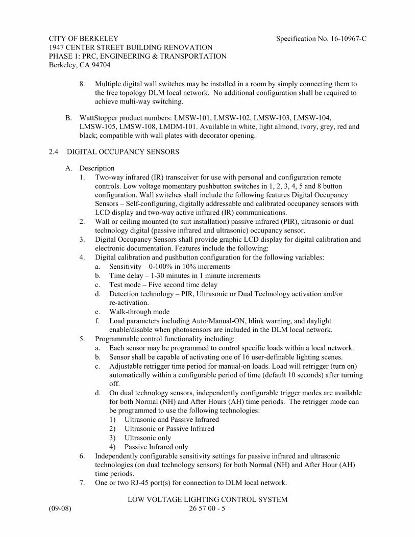
CITY OF BERKELEY Specification No. 16-10967-C1947 CENTER STREET BUILDING RENOVATIONPHASE 1: PRC, ENGINEERING & TRANSPORTATIONBerkeley, CA 94704
LOW VOLTAGE LIGHTING CONTROL SYSTEM(09-08) 26 57 00 - 5
8. Multiple digital wall switches may be installed in a room by simply connecting them tothe free topology DLM local network. No additional configuration shall be required toachieve multi-way switching.
B. WattStopper product numbers: LMSW-101, LMSW-102, LMSW-103, LMSW-104,LMSW-105, LMSW-108, LMDM-101. Available in white, light almond, ivory, grey, red andblack; compatible with wall plates with decorator opening.
2.4 DIGITAL OCCUPANCY SENSORS
A. Description1. Two-way infrared (IR) transceiver for use with personal and configuration remote
controls. Low voltage momentary pushbutton switches in 1, 2, 3, 4, 5 and 8 buttonconfiguration. Wall switches shall include the following features Digital OccupancySensors – Self-configuring, digitally addressable and calibrated occupancy sensors withLCD display and two-way active infrared (IR) communications.
2. Wall or ceiling mounted (to suit installation) passive infrared (PIR), ultrasonic or dualtechnology digital (passive infrared and ultrasonic) occupancy sensor.
3. Digital Occupancy Sensors shall provide graphic LCD display for digital calibration andelectronic documentation. Features include the following:
4. Digital calibration and pushbutton configuration for the following variables:a. Sensitivity – 0-100% in 10% incrementsb. Time delay – 1-30 minutes in 1 minute incrementsc. Test mode – Five second time delayd. Detection technology – PIR, Ultrasonic or Dual Technology activation and/or
re-activation.e. Walk-through modef. Load parameters including Auto/Manual-ON, blink warning, and daylight
enable/disable when photosensors are included in the DLM local network.5. Programmable control functionality including:
a. Each sensor may be programmed to control specific loads within a local network.b. Sensor shall be capable of activating one of 16 user-definable lighting scenes.c. Adjustable retrigger time period for manual-on loads. Load will retrigger (turn on)
automatically within a configurable period of time (default 10 seconds) after turningoff.
d. On dual technology sensors, independently configurable trigger modes are availablefor both Normal (NH) and After Hours (AH) time periods. The retrigger mode canbe programmed to use the following technologies:1) Ultrasonic and Passive Infrared2) Ultrasonic or Passive Infrared3) Ultrasonic only4) Passive Infrared only
6. Independently configurable sensitivity settings for passive infrared and ultrasonictechnologies (on dual technology sensors) for both Normal (NH) and After Hour (AH)time periods.
7. One or two RJ-45 port(s) for connection to DLM local network.

CITY OF BERKELEY Specification No. 16-10967-C1947 CENTER STREET BUILDING RENOVATIONPHASE 1: PRC, ENGINEERING & TRANSPORTATIONBerkeley, CA 94704
LOW VOLTAGE LIGHTING CONTROL SYSTEM(09-08) 26 57 00 - 6
8. Two-way infrared (IR) transceiver to allow remote programming through handheldcommissioning tool and control by remote personal controls.
9. Device Status LEDs, which may be disabled for selected applications, including:a. PIR detectionb. Ultrasonic detectionc. Configuration moded. Load binding
10. Assignment of occupancy sensor to a specific load within the room without wiring orspecial tools.
11. Manual override of controlled loads.12. All digital parameter data programmed into an individual occupancy sensor shall be
retained in non-volatile FLASH memory within the sensor itself. Memory shall have anexpected life of no less than 10 years.
B. Units shall not have any dip switches or potentiometers for field settings.
C. Multiple occupancy sensors may be installed in a room by simply connecting them to the freetopology DLM local network. No additional configuration will be required.
D. WattStopper product numbers: LMPX, LMDX, LMPC, LMUC, LMDC
2.5 DIGITAL PHOTOSENSORS
A. Description:1. Open loop digital photosensors shall include the following additional features:
a. Each of the three discrete daylight zones can include any non overlapping group ofloads in the room.
b. Automatically establishes application-specific setpoints following manual calibrationusing a wireless configuration tool. For switching operation, an adequate deadbandbetween the ON and OFF setpoints for each zone shall prevent the lights fromcycling; for dimming operation, a proportional control algorithm shall maintain thedesign lighting level in each zone.
c. WattStopper Product Number: LMLS-500, LMLS-500-L.
2.6 DIGITAL ROOM CONTROLLERS AND PLUG-LOAD CONTROLLERS
A. Description1. Open digital controllers for lighting and plug loads automatically bind the room loads to
the connected devices in the space without commissioning or the use of any tools. Roomand plug load controllers shall be provided to match the room lighting and plug loadcontrol requirements. The controllers will be simple to install, and will not have dipswitches or potentiometers, or require special configuration for standard Plug n’ Goapplications.
2. Each of the three discrete daylight zones can include any non overlapping group of loadsin the room.

CITY OF BERKELEY Specification No. 16-10967-C1947 CENTER STREET BUILDING RENOVATIONPHASE 1: PRC, ENGINEERING & TRANSPORTATIONBerkeley, CA 94704
LOW VOLTAGE LIGHTING CONTROL SYSTEM(09-08) 26 57 00 - 7
3. Digital controllers for lighting and plug loads automatically bind the room loads to theconnected devices in the space without commissioning or the use of any tools. Room andplug load controllers shall be provided to match the room lighting and plug load controlrequirements. The controllers will be simple to install, and will not have dip switches orpotentiometers, or require special configuration for standard Plug n’ Go applications
4. Multiple room controllers connected together in a local network must automaticallyprioritize each room controller, without requiring any configuration or setup, so that loadsare sequentially assigned using room controller device ID’s from highest to lowest.
5. Dual voltage (120/277 VAC, 60 Hz), or 347 VAC, 60 Hz (selected models only). 120/277volt models rated for 20A total load, derating to 16A required for some dimmed loads(forward phase dimming); 347 volt models rated for 15A total load; plug load controllerscarry application-specific UL 20 rating for receptacle control.
6. Zero cross circuitry for each load7. All digital parameter data programmed into an individual room controller or plug load
controller shall be retained in non-volatile FLASH memory within the controller itself.Memory shall have an expected life of no less than 10 years.
8. Device Status LEDs to indicate:a. Data transmissionb. Device has powerc. Status for each loadd. Configuration status
B. On/Off Room Controllers shall include:1. One or two relay configuration2. Efficient 150 mA switching power supply3. Three RJ-45 DLM local network ports with integral strain relief and dust cover4. WattStopper product numbers: LMRC-101, LMRC-102
C. On/Off/Dimming enhanced Room Controllers shall include:1. Real time current monitoring2. Multiple relay configurations
a. One, two or three relays (LMRC-21x series)b. One or two relays (LMRC-22x series)
3. Efficient 250 mA switching power supply4. Four RJ-45 DLM local network ports with integral strain relief and dust cover5. One dimming output per relay
a. 0-10V Dimming - Where indicated, one 0-10 volt analog output per relay for controlof compatible ballasts and LED drivers. The 0-10 volt output shall automaticallyopen upon loss of power to the Room Controller to assure full light output from thecontrolled lighting. (LMRC-21x series)
b. Line Voltage, Forward Phase Dimming - Where indicated, one forward phase controlline voltage dimming output per relay for control of compatible two-wire orthree-wire ballasts, LED drivers, MLV, forward phase compatible ELV, neon/coldcathode and incandescent loads. (LMRC-22x series)

CITY OF BERKELEY Specification No. 16-10967-C1947 CENTER STREET BUILDING RENOVATIONPHASE 1: PRC, ENGINEERING & TRANSPORTATIONBerkeley, CA 94704
LOW VOLTAGE LIGHTING CONTROL SYSTEM(09-08) 26 57 00 - 8
c. Each dimming output channel shall have an independently configurable minimumand maximum calibration trim level to set the dimming range to match the truedynamic range of the connected ballast or driver.
d. The LED level indicators on bound dimming switches shall utilize this newmaximum and minimum trim.
e. Each dimming output channel shall have an independently configurable minimumand maximum trim level to set the dynamic range of the output within the new0-100% dimming range defined by the minimum and maximum calibration trim.
f. Calibration and trim levels must be set per output channel.g. Devices that set calibration or trim levels per controller are not acceptable.h. All configuration shall be digital. Devices that set calibration or trim levels per
output channel via trim pots or dip-switches are not acceptable.6. Each load shall have an independently configurable preset on level for Normal Hours and
After Hours events to allow different dimmed levels to be established at the start of bothNormal Hours and After Hours events.
7. Fade rates for dimming loads shall be specific to bound switch buttons, and the load shallmaintain a default value for any bound buttons that do not specify a unique value.
8. The following dimming attributes may be changed or selected using a wirelessconfiguration tool:a. Establish preset level for each load from 0-100%b. Set high and low trim for each loadc. Set lamp burn in time for each load up to 100 hours
9. Override button for each load provides the following functions:a. Press and release for on/off controlb. Press and hold for dimming control
10. WattStopper product numbers: LMRC-211, LRMC-212, LRMC-213, LMRC-221,LMRC-222
D. Plug Load Room Controllers shall include:1. One relay configuration with additional connection for unswitched load2. Configurable additive time delay to extend plug load time delay beyond occupancy sensor
time delay (e.g. a 10 minute additive delay in a space with a 20 minute occupancy sensordelay ensures that plug loads turn off 30 minutes after the space is vacated).
3. Factory default operation is Auto-on/Auto-off, based on occupancy4. Real time current monitoring of both switched and un-switched load (LMPL-201 only)5. Efficient switching power supply
a. 150mA (LMPL-101)b. 250mA (LMPL-201)
6. RJ-45 DLM local network portsa. Three RJ-45 ports (LMPL-101)b. Four RJ-45 ports (LMPL-201)
7. WattStopper product numbers: LMPL-101, LMPL-201.

CITY OF BERKELEY Specification No. 16-10967-C1947 CENTER STREET BUILDING RENOVATIONPHASE 1: PRC, ENGINEERING & TRANSPORTATIONBerkeley, CA 94704
LOW VOLTAGE LIGHTING CONTROL SYSTEM(09-08) 26 57 00 - 9
PART 3 - EXECUTION
3.1 INSTALLATION
A. Description1. Digital Switches and/or photocells shall be mounted in the spaces as indicated on the
Drawings. Each low voltage wire shall be labeled clearly indicating which relay panel itconnects to. Use only Watt Stopper pre-terminated LMRJ series Cat 5e cable as indicatedon the Drawings. All relays and switches shall be tested after installation to confirmproper operation and the loads recorded on the directory card in each panel.
3.2 PROGRAMMING
A. All programming shall comply with Title 24 requirements (i.e. automatic control and overridelimits).
B. Test all programming for proper operation of each relay at scheduled times.
3.3 SYSTEM STARTUP
A. The Manufacturer shall provide a factory authorized technician to commission and confirmproper installation and operation of all system components.
B. Contractor shall provide system documentation after the equipment has been installed:1. Lighting control operational summary sheet.2. Programming record sheet.3. System Installation and Operation Manual shall be provided to the owner.
3.4 TESTS
A. Test under provisions of Section 26 05 00 and 26 08 00.
B. The Owner shall be notified at least three working days in advance of the Contractor'sproposed date of the tests to permit scheduling, and to permit witnessing of the tests. TheContractor shall furnish the Owner with three copies of the results of the tests.
C. Circuits: The Contractor shall test each circuit, all controllers, and components of the systemfor proper operation. The Contractor shall furnish the Owner with three copies of the testresults.
D. Operating Test: Contractor shall operate the system in the presence of the Owner proving theproper operation of the system and all components.
END OF SECTION

CITY OF BERKELEY Specification No. 16-10967-C1947 CENTER STREET BUILDING RENOVATIONPHASE 1: PRC, ENGINEERING & TRANSPORTATIONBerkeley, CA 94704
VOICE AND DATA COMMUNICATION SYSTEM(09-08) 27 00 00 - 1
SECTION 27 00 00VOICE AND DATA COMMUNICATION SYSTEM
PART 1 – GENERAL
1.1 DESCRIPTION
A. This project includes the provisions for and installation of a complete telecommunicationssystem pathways and wiring infrastructure system for the renovated areas, including allterminations, testing, and all related passive components required for operation.
1.2 WORK INCLUDED
A. Work included in this Section: All materials, labor, equipment, services, and incidentalsnecessary to install the work as shown on the drawings and as specified hereinafter, including,but not limited to the work listed below.
B. Provide and install complete and functional voice and data communication system, includingall necessary passive components, to allow full operation of the wiring infrastructure systemupon completion.
C. The installation shall include all cable, inner-duct, conduit, interconnect / patching equipment,connectors/adapters, splices, patch cords and jumpers, wiring blocks, data and voice outlets,wireless communications system antenna connections, and any other equipment specifiedherein.
D. The install action shall not include any active network components such as routers, switches,hubs, fiber optic transceivers, wireless communications system transceivers, antennae, basestations and concentrators or servers, which shall be supplied by the owner.
E. Upon completion of the installation, this contractor shall test all copper pathways and recordthe test results as specified herein.
F. The scope of work under this Section shall include any other work as might reasonably beimplied as required, even though not specifically mentioned herein or shown on the drawings.
1.3 RELATED WORK
A. Division 01 – General Requirements.
B. Division 09 – Finishes.
C. Section 26 05 00 – Basic Electrical Requirements
D. Section 26 27 00 – Basic Electrical Materials & Methods

CITY OF BERKELEY Specification No. 16-10967-C1947 CENTER STREET BUILDING RENOVATIONPHASE 1: PRC, ENGINEERING & TRANSPORTATIONBerkeley, CA 94704
VOICE AND DATA COMMUNICATION SYSTEM(09-08) 27 00 00 - 2
E. Equipment and work provided by the owner’s network integrator, including owner providednetwork servers, switches, hubs, optical fiber transceivers, routers, wireless communicationsystem equipment, etc.
1.4 INCORPORATED DOCUMENTS
A. Requirements of the General Conditions, supplementary conditions, and Division 01 Sectionsapply to the work of this section, unless modified herein.
B. Published specifications, standard tests or recommended methods of trade, industry orgovernment organizations shall apply to work of this section where cited by abbreviationsnoted below, unless modified herein.1. National Electrical Code, latest edition, (NEC), Article 800-4.2. Underwriters’ Laboratories, Inc. (UL), UL 1459, UL 1863.3. TIA/EIA-569-A “Commercial Building Standard for Telecommunications Pathways and
Spaces.”4. TIA/EIA-568-B. “Commercial Building Telecommunication Standard”.5. IEEE 802.3 “Carrier Sense Multiple Access With Collision Detection”.6. ANSI / TIA - 568-C.1 “Commercial Building Telecommunications Cabling”.7. IEEE B02.11b “Wireless Network standard”8. TIA / EIA – 606 “Labeling and marking standards for cable and pathways.”
1.5 CONTRACTOR QUALIFICATIONS
A. Contractor must possess a valid state Contractor’s License and must have successfullyperformed at least three projects of similar scope, within two years of the date of this bid. Proof of performance shall be in the form of reference sheets, which shall include a briefdescription of the project, the beginning and ending contract price, the project foreman orsuperintendent’s name, and the name, address, and telephone number of a project contact.
B. Contractor must be able to prove to the satisfaction of Owner that it has significant experiencein the installation of optical fiber cable systems. Installation must include installation ofoptical fiber cable, fiber termination, knowledge of interconnect equipment, and a thoroughknowledge of testing procedures. Contractor must provide a minimum of three referencessupporting its claim of experience for similar projects within the two years prior to this bid. Documentation must be included with the bid documents submitted.
C. Contractor must have been in business and in the business of installing telecommunicationssystems, continuously, for a period of at least three years, prior to the date of this bid.
1.6 SUBMITTALS
A. General: Comply with the requirements of section 26 05 00 – Submittals.
B. Submit complete list of all items of materials to be furnished, and installed to the owner forcompliance review prior to purchasing the materials. Submittals shall include:

CITY OF BERKELEY Specification No. 16-10967-C1947 CENTER STREET BUILDING RENOVATIONPHASE 1: PRC, ENGINEERING & TRANSPORTATIONBerkeley, CA 94704
VOICE AND DATA COMMUNICATION SYSTEM(09-08) 27 00 00 - 3
1. Complete bill of materials and equipment, including a complete listing of thecharacteristics of the equipment as specified.
2. One line diagram indicating all system connections, all closet locations, rackarrangements, cabinets, and workstation outlets.
3. Fiber frame Rack and communications cabinet layouts and dimensions.4. Samples of proposed cable markers and labeling, and patch panel and connector block
labeling and color-coding.5. List of instrumentation to be used for system testing, including certificate of
manufacturers calibration.6. 1/4th scale plan of all telecommunications rooms and closets, indicating proposed layout
of all equipment and cable trays, troughs, and runways.7. Manufacturer's warranty application for the indicated project.8. Schdule of work completion coordinated with the General Contractor.
C. Submit Contractor’s qualifications as outlined in Section 1.03 above.
D. Submit “as-built” record drawings at the completion of the installation and testing.
E. The Contractor shall submit all testing documentation prior to acceptance of the work by theOwner.
F. Contractor shall submit to the Owner, in writing, 48 hours advance notice when testing ofoptical fiber cable will begin.
1.7 GENERAL REQUIREMENTS
A. The voice and data communications system shall consist of four components:1. Twisted pair copper workstation cabling (voice and data).
B. From each IDF, one or more twisted-pair copper cables shall be routed to each data and voiceoutlet location, (and one cable to each wireless antenna location), as indicated on the drawings.1. The wiring system shall be provided and installed per TIA / EIA-568-B star wiring
topology and shall be Category 6A rated for both data and voice.2. Fully shielded twisted pair (FTP) cable, installed for high-speed data application, shall not
exceed 295 feet in length between terminations.
C. Terminations:1. All data and voice cables and wireless communications cables shall be terminated on
modular patch panels.2. All active equipment will be provided and installed by the owner.
D. The MDF and IDF will also house active data distribution equipment provided by the owner,possibly including but not limited to local area network hubs and switches, optical fibertransceivers, wireless communication systems base stations and concentrations routers, andservers. This Contractor shall coordinate with Owner’s network integrator to ensure that datarack and cabinet layouts fully accommodate all owner-provided equipment.

CITY OF BERKELEY Specification No. 16-10967-C1947 CENTER STREET BUILDING RENOVATIONPHASE 1: PRC, ENGINEERING & TRANSPORTATIONBerkeley, CA 94704
VOICE AND DATA COMMUNICATION SYSTEM(09-08) 27 00 00 - 4
1.8 FUNCTION AND OPERATION
A. The function of the data communications cable system is to transmit data signals from a centrallocation to multiple individual data outlet locations. Upon completion of the work outlined inthis specification, the entire cable system, including cable, and communications outlets shall betested to (and meet) Category 6A compliance.
1.9 GUARANTEE
A. The Cabling System shall meet the performance requirements of the ANSI/TIA/EIA-568-Bstandard. The warranty on the material, services, and operation of the cabling system to thisspecification must be for a period of at least 15 years. The connecting hardware shall have alifetime extended warranty against defects in material and workmanship.
B. The warranty must include the following statements regarding the cabling system:1. “Will support and conform to TIA/EIA-568-B specifications covering any current or
future application which supports transmission over a properly constructed horizontalcabling system premises network which meets the channel and/or basic link performanceas described in TIA/EIA-568-B”.
2. “Will be free from defects in material or faulty workmanship for the entire warrantyperiod”.
PART 2 – PRODUCTS
2.1 ACCEPTABLE MANUFACTURERS
A. Copper & Fiber Cable
Superior Essex, Avaya, Siecor, or equal
B. Fiber Optic Distribution Panels and Interconnects
Leviton, ADC Telecommunications, Siecor, or equal
C. Copper Patch Panels and Devices
Leviton, Avaya, Ortronics, Siemon, or equal
D. Cabinets and Racks
ESW (Encore), Leviton, Homaco, Chatsworth, or equal
E. Innerduct
Endot, or equal
F. Firestopping

CITY OF BERKELEY Specification No. 16-10967-C1947 CENTER STREET BUILDING RENOVATIONPHASE 1: PRC, ENGINEERING & TRANSPORTATIONBerkeley, CA 94704
VOICE AND DATA COMMUNICATION SYSTEM(09-08) 27 00 00 - 5
STI (Specified Technologies, Inc.), 3M, or equal
G. Steel Wire Cable Tray:
Mono-Mesh, GS Metals, or equal
H. Cable Runway:
B-Line, Chatsworth, Mono-System Inc, or equal
I. Fiber Optic Cable Trough:
ADC Telecommunications, or equal
2.2 MATERIALS
A. Copper Cable:1. Horizontal distribution cable (for both data and voice) in conduit shall consist of four
shielded twisted pairs, #23 AWG, Cat. 6A type CMR or equal, with the followingcharacteristics:a. Characteristic impedance @ 1.0 – 250.0 MHz: 100 Ohms (+) 22%b. Meet or exceed TIA/EIA-568-B, Category 6A.
2. Horizontal distribution cable (for both data and voice), where not installed in conduit inplenum spaces, shall be plenum rated and consist of four shielded twisted pairs, #23AWG, Cat. 6A type CMP or equal, with the following characteristics:a. Characteristic impedance @ 1.0 – 250.0 MHz: 100 Ohms (+) 22%b. Meet or exceed TIA/EIA-568-B, Category 6A
3. Horizontal cable for both data and voice shall meet the following requirements.a. Cable jacket marking: Must be legible and shall contain the following information:
1) Manufacturer’s name.2) Copper conductor gauge.3) Pair counts.4) UL and CSA listing.5) Manufacturer’s trademark.6) Category rating.7) Sequential foot markings, in 2-foot increments.
b. Data and voice station cable jacket shall be blue with black lettering and shall be in1000-foot boxes.
c. Type CMR cable shall be solid annealed copper with polyolefin insulation rounddesign with flexible web separator with flame retardant PVC jacket.
d. Type CMP cable shall be same as Type CMR except with type FEP insulation.4. Data Equipment Inter-Connect patch Cords: Four twisted-pair stranded, Category 6A
Enhanced Power Sum, 24 AWG copper conductors. Individual conductors PVC jacketed. Each conductor provided with unique color code. Manufacturer terminated on each endwith Category 6A, 8-pin / 8-position modular plug to be pinned as per EIA / TIA 568 B.

CITY OF BERKELEY Specification No. 16-10967-C1947 CENTER STREET BUILDING RENOVATIONPHASE 1: PRC, ENGINEERING & TRANSPORTATIONBerkeley, CA 94704
VOICE AND DATA COMMUNICATION SYSTEM(09-08) 27 00 00 - 6
Connector plug shall be polarized to prevent polarity reversal or split pairs, and shall befactory-marked to indicate top of connector. Inter-connect cord shall be UL listed.a. The Contractor shall complete data interconnects between patch panels and
Owner-provided active network electronics.b. Minimum performance specifications:
1) The data equipment inter-connect cable must meet the impedance, attenuationand NEXT requirements for Category 6A Horizontal Cable of EIA / TIA 568 B.
c. Lengths as required running from the data station cable terminations to the ports onequipment mounted in any rack position. Minimum length shall be 5 feet and themaximum length shall be 15 feet.
B. Data and Voice Outlets1. Cable termination hardware shall be individual; Category 6A Channel rated Leviton (or
equal) jacks for both data and voice. The listed product shall have the followingcharacteristics:a. One eight-position, eight-conductor jack (nonkeyed), TIA/EIA-568-B Compliant,
wired to T568B, Leviton category 6A.b. The cover of the information outlet shall be labeled above the jack. The number on
the outlet jacks shall coincide with the identification requirements listed in Section3.01-S-3 below.
c. The color of all voice and data jacks shall be white.d. The color of all faceplates and blank inserts or visible mounting plates shall match
the adjacent power or signal outlet covers on the project (provided under anothersection).
e. The devices at outlets and the devices in the patch panels shall be of the samemanufacturer and same type.
f. See Drawings for number of jacks at each outlet, jack arrangement, and mountingtype.
2. The 8-pin 8-position jacks at terminal blocks and at each 4-pair termination shall belabeled with laser-printed polyester self-laminating wrap-around labels.a. Eight-pin 8-position jack label-faceplates;
1) All labels shall be polyester and white in color;2) All labels shall be 1.80-inch in width and 0.375-inch in length;3) Labels shall have an adhesive backing;4) Labels shall be attached to the faceplate by adhesive and clipping in behind the
snap in clear plastic cover;5) Labels shall be laser printed with the labeling scheme as specified;6) Labels shall be Panduit Pan-CODE Laser Labels (PLL) part EFPL-1, Leviton
LabelWare, or equal.b. Terminal block designation strip:
1) All labels shall be polyester;2) Labels shall be white in color for 4-pai data station cable terminations, located
within a blue plastic label holder;3) Labels shall be attached to the designation strip provided with the blue plastic
holders;

CITY OF BERKELEY Specification No. 16-10967-C1947 CENTER STREET BUILDING RENOVATIONPHASE 1: PRC, ENGINEERING & TRANSPORTATIONBerkeley, CA 94704
VOICE AND DATA COMMUNICATION SYSTEM(09-08) 27 00 00 - 7
4) All labels shall be 7.88 inches in width and 0.50 inches in length;5) Labels shall have an adhesive backing;6) Labels shall be laser-printed with the labeling scheme as specified;7) Labels shall be Panduit Pan-CODE Laser Labels (PLL) part number
PLL-22-Y3-1, Leviton LabelWare, or equal.
C. Termination Hardware at MDF / IDF’s (Data and Voice)1. All cables installed for data and voice application shall be terminated in rack-mounted
modular patch panels and the entire installation shall be in compliance withTIA/EIA-568-B Category 6A requirements.
2. Data patch panels shall be Leviton Category 6A discrete port-type. Port panels shall becertified by the manufacturer as suitable for 1000 Mbps data transmission. Patch panelsshall be manufactured of aluminum or steel.
3. Wire management hardware shall be Leviton Versi-Duct 49265 Series, or equal, installedat both the top and the bottom and between each patch panel and along the sides of therack for patch cable routing and management.
4. Wire managers shall be of sufficient width and depth to permit orderly routing of all patchcables at one hundred percent utilization.
5. Patch panels shall be mounted on equipment racks. Panels shall be affixed to the rack byat least four (4) screws. The screws shall be of the correct size and thread configurationfor the holes in the rack. They shall be tightened to the extent that they hold theequipment firmly to the rack, without distorting the equipment or stripping the threads.
PART 3 – EXECUTION
3.1 CABLE AND WIRE INSTALLATION:
A. This contractor shall be responsible for the provision and installation of all data and voicecables including all supports, hangers, and hardware necessary for a complete installation. Under no circumstances shall cables be laid on the suspended ceiling. This contractor shall beresponsible for providing and installing all necessary cable support hardware to meet Category6A requirements. Refer also to Section 26 05 00 Basic Materials & Methods:1. T-Bar Suspended Ceilings: Copper station cabling may be run outside of conduits when
routed above T-Bar suspended ceilings. Cables installed in this fashion are to be runhorizontally in bundles and tied down neatly suspended from J-hooks, and well clear ofany light fixtures or other electrical appliances that may affect data transmissions.
B. At each voice/data closet cables are to be segregated by type, neatly tied together and routed tothe patch panels. All cables shall be tagged.
C. Cable distances from patch panels to data outlet shall not exceed 295 feet. This contractor isresponsible to ensure the distance specified is not exceeded.
D. Care shall be exercised in routing both station and backbone/tie cables so as to avoid areaswhere sources of high levels of EMI (such as electric motors, transformers and fluorescent

CITY OF BERKELEY Specification No. 16-10967-C1947 CENTER STREET BUILDING RENOVATIONPHASE 1: PRC, ENGINEERING & TRANSPORTATIONBerkeley, CA 94704
VOICE AND DATA COMMUNICATION SYSTEM(09-08) 27 00 00 - 8
lighting fixtures) may exist. Maintain a minimum distance of 12 from these sources when runparallel. Cross at 90-degree angles where crossing must occur.
E. Each station cable shall be “home run” (no splices or cross connection points) between jacksand patch panels.
F. All openings or raceway transitions through firewalls and floors shall utilize UL listedfire-rated penetrations.
G. No more than (2) 90-degree bends shall be allowed on all conduit runs for the horizontalvoice/data cabling system, without an intermediate pullbox or junction box.
H. Station cable terminations.1. Cable pair twists of Category 6A Cable shall be maintained within 0.25-inch of the point
of termination. Under no circumstances shall cable pairs be untwisted or otherwisealtered prior to termination.
2. Do not bend Category 6A station cables to a radius of less than 10 times the cablediameter.
3. Allow slack in Category 6A Cable bundles at entrances and exits of conduit sleeves and attransitions from “J” hooks to cable trays. Never pull cables tight at cable tray transitions;doing so may damage the cables by crimping them on the cable tray side of the bundles.
4. Keep the cable evenly distributed within the cable tray. Do not allow the cables orbundles to be pulled tight against the splines or to be unevenly balanced on one side of thetray.
5. Bundles of station cable in floor slots shall not exceed 2.5 inches in diameter, and shall bespaced 4 inches apart for proper fire stopping of the floor slot.
6. Bundles of station cable in 4-inch floor sleeves shall not exceed a 39 percent fill.
I. Where fiber or copper cable enters an equipment room or voice/data closet, it shall be affixedto the backboard via “D” Rings and cable ties. All cable shall be neatly bundled, combed, andtied. All exposed cable runs shall be horizontal or vertical, and bends shall comply withmanufacturer required minimum cable bending radii.
J. All openings into wall mounted cabinets and fiber optic distribution panels shall be grommet.
K. Provide (1) patch cable for each activated jack on the project. Lengths shall be 5ft. minimumor as required for the MDF or IDF design.
L. Provide 3 pair jumper cables as required for all voice system cross-connects at telephonebackboards.
M. Labeling: Labeling shall include, but not be limited to:1. Labeling telecommunications outlet faceplates;2. Labeling station cables;3. Labeling terminal blocks;4. Labeling of telecommunications pathways, including conduits, steel wire cable trays,
cable runway and pullboxes;

CITY OF BERKELEY Specification No. 16-10967-C1947 CENTER STREET BUILDING RENOVATIONPHASE 1: PRC, ENGINEERING & TRANSPORTATIONBerkeley, CA 94704
VOICE AND DATA COMMUNICATION SYSTEM(09-08) 27 00 00 - 9
5. Labeling of all grounding conductors and ground bars in the Intermediated DistributionFacilities (IDFs) and Main Distribution Facility (MDF).
6. The intent of the final labeling is to allow the Owner or persons contracted by the Ownerto identify any part of the structured cabling system through physical identification of thecomponents and their related components at the specified access point without the use ofelectrical, electronic or mechanical means of identification.
7. Equipment rack and cable tray / pullbox labels:a. Equipment Racks shall be clearly labeled as follows:
1) Labels shall be adhesive backed individual letters and numbers.2) Individual letters shall be 3/4*-inch in width and 1-inch in height.3) Individual characters shall be self-spacing by simply butting the individual
characters against each other in a row.4) Characters shall be either white or yellow on a black background.5) Labels shall be designed for exposed outdoor applications.6) Labels shall be:
(a) 3M Scotchcal 5003 Non-Reflective Lettering Systems.(b) Panduit, PVL100YB.(c) Or equal.
8. Copper station – cable sheath labels:a. Copper station cable sheaths at 8-pin 8-position jacks, at junction boxes, enclosures,
and pull boxes shall be labeled with laser-printed polyester self-laminatingwrap-around labels.1) All labels shall be polyester with white color.2) All labels shall be at least 1.00- inches in width and 1.33-inch in length; with a
0.5-inch x 1-inch printable area;3) Labels shall have an adhesive backing;4) Labels shall be attaché to cable sheaths by wrapping around the sheath with the
adhesive back self-laminating portion;5) Labels shall be laser printed with the labeling scheme as specified;
9. Copper and fiber optic data interconnect cable sheath labels:a. Copper data interconnect cable sheaths shall be labeled with laser printed polyester
self-laminating labels at each end.1) All labels shall be polyester with white color.2) All labels shall be at least 1.87- inches in width and 3.167-inch in length; with a
0.5-inch x 1-inch printable area;3) Labels shall have an adhesive backing;4) Labels shall be attached to cable sheaths by wrapping around the sheath and
creating a flag with the label body and clear laminating portion.5) Labels shall be laser-printed with the labeling scheme as specified.
10. Cable / outlet / jack / termination identification:a. Each copper cable, its associated 568A jack at the outlet, and the associated C-4
connecting block on the terminal block or patch panel shall be labeled with a uniqueidentifier consisting of the following:1) The IDF room number where the station cable is terminated, ###.

CITY OF BERKELEY Specification No. 16-10967-C1947 CENTER STREET BUILDING RENOVATIONPHASE 1: PRC, ENGINEERING & TRANSPORTATIONBerkeley, CA 94704
VOICE AND DATA COMMUNICATION SYSTEM(09-08) 27 00 00 - 10
2) The end user room number in which the 4-pair cable is terminated and thetelecommunications outlet is located, ###.
3) A 3-digit serial number, rest to 001 for each room, which sequentially identifieseach telecommunications jack / cable in a room, ###.
4) The type of service provided by a Particular cable, either D for data or V forvoice.
5) Example of IDF 107, user room 129, jack /cable number 1 (data cable): 107-129-001-D.
b. The following are examples of the numbering scheme:1) IDF room 1.1, User Rm. 111, Jack/ cable 1, Data line.
1.1-111-001-D(a) IDF Number: 1.1(b) Room Number: 111(c) Serial Number: 001(d) Data Line: D
2) IDF room 1.1, User Rm. 106, Jack / cable, Voice line.1.1-106-001-V(a) IDF Number: 1.1(b) Room Number: 106(c) Serial Number: 001(d) Voice Line: V
11. Cable identification:a. Each fiber optic backbone cable sheath shall be labeled with a unique identifier as
shown on the Drawings.b. Label the cable sheath at the termination shelf and on the innerduct as the fiber optic
cables pass through IDFs and pull boxes.c. Each SC connector in each termination shelve shall be labeled with a unique
identifier as noted on the Drawings.12. Cable sheath identification:
a. Identify multi-pair copper riser cable sheaths with machine-generated labels at thefollowing locations:1) Within 12 inches of the point that the cable exits the top or bottom of the
110P-type terminal block column.2) Within 12 inches of the point that the cable enters a splice.3) At 40-foot intervals above T-Bar ceilings.4) At pull boxes5) Within 12 inches of the point that the cable enters or exits wall and floor
sleeves.13. Cable pair identification:
a. Identify all riser cable pairs in 5-pair increments on a 110 terminal block designationstrip. The numbering shall be 4 digits beginning with “0001” and continuing through“0800”. The Contractor shall provide white, laser printer generated designationstrips.
b. Identify all riser cable pairs in 5-pair increments on 25-pair connectors. Thenumbering shall be 4 digits beginning with “0001” and continuing through “0800”.

CITY OF BERKELEY Specification No. 16-10967-C1947 CENTER STREET BUILDING RENOVATIONPHASE 1: PRC, ENGINEERING & TRANSPORTATIONBerkeley, CA 94704
VOICE AND DATA COMMUNICATION SYSTEM(09-08) 27 00 00 - 11
3.2 GROUNDING SYSTEM AND CONDUCTORS
A. Bonding and Grounding:1. Communication bonding and grounding shall be in accordance with the NEC and NFPA.
Horizontal cables shall be grounded in compliance with ANSI/NFPA 70 and localrequirements and practices. Horizontal equipment includes cross connect frames, patchpanels and racks, active telecommunication equipment and test apparatus and equipment.
B. Telecommunications Bonding Backbone:1. Provide a Telecommunications Bonding Backbone utilizing a minimum #6 AWG bonding
conductor (or as shown on drawings) that provides direct bonding between equipmentrooms and telecommunications closets. Connect this bonding backbone cable to the maingrounding electrode system at the electric service switchboard.
2. Provide a copper ground bar at each tel/data equipment room or rack location, connectedto the bonding backbone.
3. Provide a #6 AWG stranded copper cable from each ground bar to each adjacent rack orcable trays system.
3.3 FIRE AND SMOKE PARTITION PENETRATIONS
A. Conduit sleeves shall be provided as part of this contract as a means of routing cables throughfire-rated walls and floors. Openings in sleeves and conduits used for system cables and thosethat remain (empty) spare shall be sealed with an approved fireproof, removable saggingmaterial at completion. Sleeves, which pass vertically from floor to floor, shall be sealed in asimilar manner using an approved re-enterable system. Additional penetrations through ratedassemblies, necessary for passage of voice/data wiring, shall be made using an approvedmethod and permanently sealed after installation of cables.
3.4 PLYWOOD BACKBOARDS
A. Plywood backboards shall be fastened to the structural members of the building only using anapproved fastener. Plywood backboards shall not be anchored to GBW.
B. Plywood shall be mounted form +6-inches AFF to +8 feet 6-inches at the locations indicatedon the Drawings.
C. Plywood backboards shall be cut to fit in width and shall have holes cut into the backboard toaccommodate and provide access to devices behind the backboard, such as switches andoutlets.
3.5 TESTING AND DOCUMENTATION
A. Refer also to Section 26 08 00 – Testing.
B. The Owner reserves the right to have a representative present during all or a portion of thetesting process. If the Owner selects to be present during testing, results will only beacceptable when conducted in the presence of the Owner.

CITY OF BERKELEY Specification No. 16-10967-C1947 CENTER STREET BUILDING RENOVATIONPHASE 1: PRC, ENGINEERING & TRANSPORTATIONBerkeley, CA 94704
VOICE AND DATA COMMUNICATION SYSTEM(09-08) 27 00 00 - 12
3.6 COPPER CABLE TESTING AND DOCUMENTATION
A. Copper Cable pair connector terminations:1. During copper connector termination, visually verify all terminations.
a. Assure proper seating of connector block on terminal strips of all insulationdisplacement connectors;
b. Assure proper seating of splice connector modules;c. Assure proper twist in cable pairs is maintained at terminations and splices.d. All unacceptable connectors shall be inspected after rework.
2. Verify that the copper cable sheath is properly clamped at the splice closures to eliminatestrain on the copper pair terminations.
3. Verify that the copper cable sheaths are properly bonded at splice closures andterminations.
4. Verify that all labeling and color-coding is correct.
B. Paired and multi-conductor riser metallic cables:1. After terminating and splicing the cables, test all cable pairs for continuity, ground fault,
proper cross-connection, shorts and crossed pairs.2. For multi-pair cables: For 100-pair or smaller, replace entire cable if bad pair or
conductor is found. For larger pair counts cables, replace if more than 1 percent of pairsare bad.
C. All test results and corrective procedures are to be documented and submitted to the Ownerwithin 5 working days of test completion.1. Paired and multi-conductor metallic cable test reports: As a minimum, also provide cable
number, cable type, pair or conductor count, individual pair or conductor numbers numberof cross connects and / or conductor, total number of serviceable pairs or conductors incable.
D. Prior to testing of installed cable, submit for review and approval of Owner copies of 5complete test reports on diskette, as a test to insure that the Contractor understands the testingand submittal process. This will prevent the Contractor from testing a large group of tablesincorrectly that would have to be re-tested.
E. Four-pair Category 6A station cables testing and submittal process:1. Submit cable schedule and testing schedule to Owner’s Representative.2. After terminating both ends of all FTP cables, test all FTP Category 6A station cables.
Conduct tests with a 110 to 8-pin 568A patch cable in place on both ends.3. Each jack in each outlet shall be tested for TIA/EIA-568-B Category 6A compliance,
using an appropriate testing instrument, to verify both the integrity of all conductors andcorrectness of the termination sequence. Testing shall be performed between modularjacks at the outlets and the modular jacks at the patch panels.
4. Test Criteria: The system shall be tested to TIA/EIA-568-B Category 6A. The test pathshall include jacks, station cables, jack panels, and adapter cables.
5. Documentation – Copper Cabling:
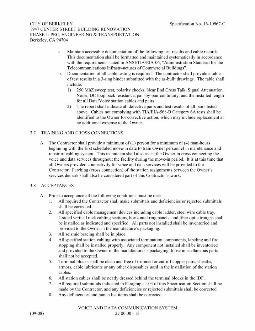
CITY OF BERKELEY Specification No. 16-10967-C1947 CENTER STREET BUILDING RENOVATIONPHASE 1: PRC, ENGINEERING & TRANSPORTATIONBerkeley, CA 94704
VOICE AND DATA COMMUNICATION SYSTEM(09-08) 27 00 00 - 13
a. Maintain accessible documentation of the following test results and cable records. This documentation shall be formatted and maintained systematically in accordancewith the requirements stated in ANSI/TIA/EIA-06, “Administration Standard for theTelecommunications Infrastr4uctures of Commercial Buildings”.
b. Documentation of all cable testing is required. The contractor shall provide a tableof test results in a 3-ring binder submitted with the as-built drawings. The table shallinclude:1) 250 MhZ sweep test, polarity checks, Near End Cross Talk, Signal Attenuation,
Noise, DC loop back resistance, pair-by-pair continuity, and the installed lengthfor all Data/Voice station cables and pairs.
2) The report shall indicate all defective pairs and test results of all pairs listedabove. Cables not complying with TIA/EIA-568-B Category 6A tests shall beidentified to the Owner for corrective action, which may include replacement atno additional expense to the Owner.
3.7 TRAINING AND CROSS CONNECTIONS
A. The Contractor shall provide a minimum of (1) person for a minimum of (4) man-hoursbeginning with the first scheduled move-in date to train Owner personnel in maintenance andrepair of cabling system. This technician shall also assist the Owner in cross connecting thevoice and data services throughout the facility during the move-in period. It is at this time thatall Owners provided connectivity for voice and data services will be provided to theContractor. Patching (cross connection) of the station assignments between the Owner’sservices demark shall also be considered part of this Contractor’s work.
3.8 ACCEPTANCES
A. Prior to acceptance all the following conditions must be met:1. All required the Contractor shall make submittals and deficiencies or rejected submittals
shall be corrected.2. All specified cable management devices including cable ladder, steel wire cable tray,
2-sided vertical rack cabling sections, horizontal ring panels, and fiber optic troughs shallbe installed as indicated and specified. All parts not installed shall be inventoried andprovided to the Owner in the manufacture’s packaging.
3. All seismic bracing shall be in place.4. All specified station cabling with associated termination components, labeling and fire
stopping shall be installed properly. Any component not installed shall be inventoriedand provided to the Owner in the manufacturer’s packaging; loose miscellaneous partsshall not be accepted.
5. Terminal blocks shall be clean and free of trimmed or cut-off copper pairs, sheaths,armors, cable lubricants or any other disposables used in the installation of the stationcables.
6. All station cables shall be neatly dressed behind the terminal blocks in the IDF.7. All required submittals indicated in Paragraph 1.03 of this Specification Section shall be
made by the Contractor, and any deficiencies or rejected submittals shall be corrected.8. Any deficiencies and punch list items shall be corrected.

CITY OF BERKELEY Specification No. 16-10967-C1947 CENTER STREET BUILDING RENOVATIONPHASE 1: PRC, ENGINEERING & TRANSPORTATIONBerkeley, CA 94704
VOICE AND DATA COMMUNICATION SYSTEM(09-08) 27 00 00 - 14
9. All as-built documentation shall be complete, reviewed and provided to the Owner.
B. Acceptance of the voice / data communications system by the Owner shall be based on theresult of testing, functionality, and the receipt of documentation and warranty. With regard totesting, contractor must provide two technicians, equipped with the specified test equipment, todo random test verification in the presence of, and at the direction of, an Owner designatedrepresentative. Verification testing shall no exceed 20% of the cable plant, provided cablestested are verified to be 100% compliant, per requirements previously stated. If more than 5%of cables tested during the verification process fail, Owner reserves the right to have the entirecable plant retested, at the contractors expense, and in the presence of an Owner-designatedrepresentative.
3.9 RECORD DRAWINGS
A. The project record drawings shall show the types, locations, cable numbers and pair counts ofinstalled twisted-pair cable:1. Cable routing and numbers.
B. The project record drawings shall show the types and locations of installed equipment racks /cabinets and fiber optic distribution frames.
END OF SECTION

ACUMEN INDUSTRIAL HYGIENE INC
1032 IRVING ST. #922 SAN FRANCISCO CA 94122
TEL 415 242 6060 FAX 415 242 6006
WWW.ACUMEN-IH.COM
Limited Asbestos Survey For Facility Repairs
for
City of Berkeley, CA
1947 Center Street Berkeley, CA
Acumen Project No. COB 1503
July, 2015
Prepared for:
Ms. Joy Brown Environmental Compliance Specialist
Public Works Department - City of Berkeley 1326 Allston Way, Berkeley, CA 94702
This report was prepared by (July 11, 2015) Paul M. Spillane, CIH, CAC Principal Industrial Hygienist Certified Asbestos Consultant: #10-4630
A

Abstract
The objective of our services is to determine the presence of asbestos containing material (ACM) in areas planned for facility upgrades and renovations. We understand upgrades and renovations will involve a multiphase remodel and repairs to the 1947 Center Street (Berkeley, CA) building that was constructed in the mid-20th Century (1947), but extensively remodeled in 1987 and 2003. A previous asbestos report from Galson Technical Services (Galson, 1987) indicated steam heating and domestic hot water thermal system insulation (TSI) contained asbestos. Plaster ceilings and vinyl floor tile were also reported to be ACM. Galson also discovered asbestos in roofing materials, but there was no mention in these reports regarding testing of exteriors. Materials that tested negative at that time included plaster walls, sheetrock, (drywall/taping mud), linoleum (vinyl sheet flooring) and ceiling tiles (splined and lay-in types). Based on subsequent Galson letter reports (1988) asbestos was consequently abated from various areas in the building, but some asbestos was left in place, including plaster ceilings the 3rd and 4th floors, vinyl floor tiles (throughout) and thermal insulation inside some pipe chases. Information was not provided regarding the 2003 remodel, however an asbestos project report indicated pipe insulation and vinyl floor tile were abated from the second floor in 2005 (Protech, 2005). The recent testing by Acumen Industrial Hygiene, Inc. (Acumen) on June 22, 2015 discovered ACM is present in exterior paint and texture on concrete, in exterior window putty and in skylight putty. We also confirmed the presence of asbestos as 9x9” vinyl floor tiles and mastics under carpets and in mechanical closets of 1st, 2nd, 3rd and 4th floors. Asbestos was not detected in pipe chase debris, drywall/taping mud, plaster walls or exterior duct tape (2nd floor roof).

Limited Asbestos Survey Report 1947 Center Street July, 2015 Berkeley, CA
TABLE OF CONTENTS
1.0 INTRODUCTION................................................................................................................................1
2.0 SUMMARY OF INVESTIGATION ..................................................................................................1 2.1 Asbestos Containing Materials Inspection Methods ....................................................................1 2.2 Previous Reports Of Asbestos Containing Materials ...................................................................2
3.0 FINDINGS AND DISCUSSION.........................................................................................................2
4.0 SUMMARY OF FINDINGS ...............................................................................................................3 4.1 Asbestos Related Findings...............................................................................................................3
5.0 RECOMMENDATIONS.....................................................................................................................4 5.1 Recommendations For ACM During Building Renovations .......................................................4 5.2 Recommendations For Managing ACM In Place (if leaving ACM in place).............................4
6.0 CONCLUSIONS ..................................................................................................................................4
APPENDIX A ANALYTICAL REPORTS AND CHAINS OF CUSTODY
APPENDIX B SAMPLE LOCATION DRAWINGS
APPENDIX C SITE PHOTOGRAPHS

Limited Asbestos Survey Report 1947 Center Street July, 2015 Berkeley, CA
Page 1 of 6
1.0 Introduction
The purpose of this report is to provide the findings of a limited asbestos containing materials (ACM) survey Acumen Industrial Hygiene, Inc. (Acumen) conducted at the above referenced facility (1947 Center Street, Berkeley, California). We understand upgrades and renovations will involve a multiphase remodel and repairs to the 1947 Center Street (Berkeley, CA) building that was constructed in the mid-20th Century (1947), but extensively remodeled in 1987 and 2003. Mr. Paul Spillane, CIH, CAC, conducted the investigation at the building(s) on June 23, 2015. The main objective of our services is to provide project guidance for complying with applicable regulations, including California Department of Occupational Safety & Health (Cal-OSHA), California Department of Toxic Substances Control (DTSC) and Bay Area Air Quality Management District (BAAQMD) as they relate to asbestos. Our scope of work was as follows:
• Sample exterior window and skylight caulking for asbestos. This material is often assumed to contain asbestos and because it gets replaced on an “as needed” based throughout the history of the building. Multiple samples are required to prove it does not contain asbestos.
• Collect asbestos samples of exterior textured paint on concrete. This will need to be disclosed to contactors working on exteriors, because their work may disturb this material.
• Sample the debris found on the basement due to the water leaks.
• Sample original drywall/plasters in the center pipe chase.
• Based on the areas of planned remodel, we understand that some flooring, ceilings and drywall will be demolished.
2.0 Summary of Investigation
2.1 Asbestos Containing Materials Inspection Methods
The inspection consisted of a walkthrough of accessible areas at the site to identify and sample suspect ACM containing materials. Acumen’s standard survey protocol is to conduct asbestos inspections in three steps: conducting a review of existing building survey records and/or drawings; physically surveying structure for suspect materials; and documenting our findings in a written report format. There were no previous survey documents of the building for review. Asbestos bulk samples are physically collected by taking a small core section of the suspect asbestos material using hand tools. Acumen noted significant factors of suspect ACM including conditions, homogeneity, locations, quantity, potential for damage or disturbance, and friability. Friability describes the ability of a material to be crushed or crumbled, when dry, into a powder using hand pressure. Where suspect materials were noted, bulk samples were collected. At the building, Acumen collected samples of various suspect ACM and lead containing materials. We collected forty-four (44) total asbestos bulk samples. Samples were given a unique identification number and submitted with our chain of custody forms to Micro Analytical Laboratories, Inc. (Emeryville, CA) for analysis. Micro Analytical Laboratories, Inc. is accredited to analyze asbestos and lead samples. Micro holds the National Institute of Standards and Technology (NIST)/ National Voluntary Laboratory Accreditation Program (NVLAP) accreditation for Transmission Electron Microscopy (TEM) (ISO/IEC 17025:1999); Polarized Light Microscopy (PLM)

Limited Asbestos Survey Report 1947 Center Street July, 2015 Berkeley, CA
Page 2 of 6
(EPA-600/M4-82-020, ISO 9002:1994) Airborne Asbestos, Lab Code #101872-0 and; NIST (NVLAP), Bulk Asbestos, Lab Code 101872-0; and AIHA ELLAP Industrial Hygiene Laboratory Program, #101768.
2.2 Previous reports of Asbestos Containing Materials
Acumen reviewed excerpts of the following reports:
• Survey for Asbestos Containing Materials at 1947 Center Street - Berkeley, California, by Galson Technical Services, May 7, 1987.
• Completion of Asbestos Removal at 1947 Center Street, by Galson Technical Services, December, 22, 1987.
• Final Report: 1947 Center Street Building - Asbestos Removal Project - 1947 Center Street – Berkeley, California. by Galson Technical Services, March 28, 1988.
• Phase I Environmental Site Assessment, Commercial Building, 1947 Center Street, Berkeley, California 94704, ATC Associates Inc., June 7, 1999.
• Asbestos Abatement Project Report, Conducted at 1947 Center Street, 2nd Floor, Berkeley, California. Protech Consulting and Engineering, March 2005.
Based on review of these reports, Galson Technical Services identified steam heating and domestic hot water insulation systems contained asbestos (Galson, 1987). Plaster ceilings and vinyl floor tile also reported to be asbestos containing materials (ACM). Galson also discovered asbestos in roofing materials, but there was no mention in the reports regarding testing of exteriors. Based on subsequent Galson letter reports (Galson, 1988) asbestos was consequently abated from various areas in the building, but some asbestos was left in place, including plaster ceilings on basement, 3rd and 4th floors, vinyl floor tiles (unclear where it was left in place) and thermal insulation inside some pipe chases. Information was not provided regarding the 2003 remodel, however a Protech asbestos project report indicated pipe insulation and vinyl floor tile were abated from the second floor in 2005 (Protech, 2005).
3.0 Findings and Discussion
The 1947 Center Street building is a six-story office building plus basement located at 1947 Center Street, Berkeley, California. The building was reportedly constructed in 1947 slab-on-grade using poured in-place concrete. The basic structure is rebar-reinforced concrete. During this recent survey, Acumen sampled exterior texture paint on concrete for asbestos. Of the seven (7) samples collected from exterior textured wall paint, asbestos was present in one of the seven (sample COB1503-01A, Photo 1). This paint is assumed to contain lead. Acumen sampled exterior window putty located between glass and metal sash at fifteen (15) locations and was also found to contain <1% to 2% asbestos in three of the 15 collected (Samples COB1503-02A, COB1503-02D and COB1503-02J, Photo 2). Acumen composite sampled the debris located at a basement closet under the pipe chase where a recent water leak has occurred. Asbestos was not detected (Sample COB1503-04A), nor was asbestos detected in the plaster walls and drywall walls tested (Samples COB1503-03A, COB1503-03B, COB1503-03C, COB1503-03D, COB1503-03E, COB1503-03F, COB1503-03G, COB1503-09A, COB1503-09B, COB1503-09C). The roofs were previously determined to contain asbestos by Galson, (1987). Acumen sampled the

Limited Asbestos Survey Report 1947 Center Street July, 2015 Berkeley, CA
Page 3 of 6
skylight putty on the second floor roof and determined it to contain 5% asbestos (Samples COB1503-05A, COB1503-05B, COB1503-05C). There is an old HVAC system on this roof and Acumen Sampled the duct tape which does not contain asbestos (Samples COB1503-06A, COB1503-06B, COB1503-06C). Asbestos flooring was found to be present on floors 1 through 4. On the first floor waiting room, brown 9x9” vinyl floor tiles are present under carpet. On the second floor, vinyl floor tiles are present are not under the carpets (where inspected), however brown 9x9” vinyl floor tiles are present in the mechanical rooms. Acumen sampled flooring under carpets on the 3rd and 4th floors and confirmed asbestos is present (Samples COB1503-07A, COB1503-07B, COB1503-07C). Previously vinyl sheet flooring (as linoleum) was indicated as none-detected by Galson (1987). We collected one sample of vinyl sheet flooring from mechanical room #322 on the third floor, which does not contain asbestos (Sample COB1503-08A). Previously plaster ceilings were reported to contain 10% asbestos by Galson (1987). Acumen did not observe plaster ceilings during our inspection, however we cannot rule out that these may be present above drop ceilings.
4.0 Summary of Findings
4.1 Asbestos Related Findings
The results of this investigation sampling determined that ACM materials are present at the following locations. These materials must be handled by a licensed abatement contractor, if impacted during the planned renovations. Asbestos Containing Materials
Materials Sampled and confirmed ACM June 23, 2015:
• Exterior textured light orange paint on concrete, Front elevation (south elevation) Ground floor – right side: Paint (Violet /Tan): 2% Chrysotile Asbestos, Texture Coating (Gray / Beige): 4% Chrysotile Asbestos (Photo 1). Note that asbestos was detected in only one (3) of the seven (7) exterior paint locations sampled;
• Window Putty: <1% to 2% Chrysotile Asbestos (Photo 2). Note that asbestos was detected in three (3) of the fifteen (15) window putties sampled;
• Skylight Caulking: 5% to 6% Chrysotile Asbestos (Photo 3);
• 9x9” vinyl floor tile and mastic: 3% to 15% Chrysotile Asbestos, mastic is inseparable (Photo 4);
Materials previously reported to contain asbestos (Galson, 1987):
• Pipe Insulation (Located in non-accessible locations such as pipe chases, risers and soffits);
• Plaster ceilings (Potentially above drop ceilings, Basement, 3rd floor and 4th floor);
• Roofing materials.
Materials that were sampled and do not contain asbestos include the following:
• Plaster walls and interior paint • Drywall/taping mud and paint • Duct Tape (Second floor roof HVAC)
• Debris in basement closet (from recent leak)
• Vinyl Sheet Flooring

Limited Asbestos Survey Report 1947 Center Street July, 2015 Berkeley, CA
Page 4 of 6
5.0 Recommendations
5.1 Recommendations for ACM During Building Renovations
1. Notify potential renovation contractors of the presence of ACM in the building. Disturbance of ACM requires special training and procedures. BAAQMD regulations require that ACM be properly removed and disposed, prior to demolition or renovation where they would be disturbed. A Cal-OSHA registered asbestos contractor is required for work that involves ACM.
2. Notify potential renovation or demolition contractors of the presumed presence of lead-containing paints at the building. Disturbance of these materials require compliance with Cal-OSHA’s lead in construction regulation.
3. Although there is no regulatory requirement for it, it would be advisable to develop either a work plan or specification for the handling of asbestos during renovations. Asbestos work should be monitored for compliance by a third party Certified Asbestos Consultant to document proper handling and disposal.
5.2 Recommendations For Managing ACM In Place (If leaving ACM in place)
1. Notify building occupants and employees of the presence of asbestos, as required under California Health & Safety Code 25915.7-25919.7 (Connelly Bill) and by Cal-OSHA regulations. The materials have a low fiber release potential if it remains undisturbed. Notify contractor and maintenance employees of this report.
2. Prepare and implement an asbestos Operations and Maintenance (O&M) program to manage ACMs that will remain in place in the building. This asbestos O&M program should detail roles and responsibilities for managing ACM at the complex. The O&M program should establish written policies and procedures for asbestos safe work practices to minimize the potential for unauthorized disturbance of ACM, monitor the condition of ACM and respond to damage or deterioration of ACM, with the goal of preventing the release of airborne asbestos fibers. Implementation of the O&M program will require that facility employees receive annual asbestos training. The O&M program should remain in place as long as ACM remains in the buildings.
3. The presence of lead based paints should also be managed under an O&M program. The O&M program should establish written policies and procedures for lead-safe work practices as required by EPA and California laws. The O&M program should establish policy for monitoring the condition of lead-based paints and respond to damage or deterioration of lead, with the goal of preventing lead poisoning.
4. The California – Proposition 65 rules require posting a sign warning of potential hazards, because of the presence of leaded paint and asbestos
6.0 Conclusions
Acumen has completed an asbestos and lead survey of 1947 Center Street (Berkeley, CA). This investigation found asbestos in exterior paint, window putty, skylight caulking and vinyl floor tiles/mastic. Previous surveys indicated the presence of asbestos thermal system insulation and ceiling plasters, which may still be present at the building in inaccessible locations. Work that disturbs these materials must be conducted by Cal-OSHA registered asbestos contractor and documented by a third party Certified Asbestos Consultant. For ACMs not abated at this time, these would need to be managed under an O&M program.

Limited Asbestos Survey Report 1947 Center Street July, 2015 Berkeley, CA
Page 5 of 6
Please feel free to contact us if you have any questions or comments regarding this report. Thank you for the opportunity to be of service.

Limited Asbestos Survey Report 1947 Center Street July, 2015 Berkeley, CA
Page 6 of 6
Limitations Reasonable effort was made by Acumen personnel to locate and sample suspect materials. However, for any facility or building, the existence of unique or concealed ACM or lead containing materials and debris is a possibility. Acumen does not warrant, guarantee, or profess to have the ability to locate or identify all ACM/ACCM or other hazardous materials at this facility. The intent of this report is for use in planning for demolition. All quantities of materials identified in this report should be field verified by contractors prior to submitting bids to perform abatement work. Additional confirmatory sampling and detailed quantification may be required if the demolition uncovers additional suspect materials. The report is not intended as a CDPH or HUD defined “lead hazard evaluation” or “lead inspection”. Acumen provided these services consistent with the level and skill ordinarily exercised by members of the profession currently providing similar services under similar circumstances at the time the services were provided. This statement is in lieu of other statements either expressed or implied. This report is intended for the sole use of the owner/client and their designees. The scope of services performed in execution of this evaluation may not be appropriate to satisfy the needs of certain other users, and use or re-use of this document, the findings, conclusions, or recommendations is at the risk of said user. As with all such assessments, the results of the sampling represent conditions found on the date of the survey and may not represent conditions found at other times. Additionally, this assessment was limited with respect to the specific parameters indicated above and should not be construed to be a comprehensive evaluation or a definitive representation of all conditions within the facility. The information presented in this report is intended to be used as a guide to evaluate the need for materials removal, further investigation or the need for modifications to the processes or procedures surveyed. The client should recognize that all testing and remediation methods have reliability limitations, no method or number of sampling locations can guarantee that a condition will be discovered within the performance of the services as authorized by the client. Additionally, the passage of time may result in a change in the environmental characteristics at this site. This report does not warrant against future operations or conditions that could affect the recommendations made. The results, findings, conclusions, and recommendations expressed in this report are based only on conditions that were observed during Acumens’ inspection of the site.
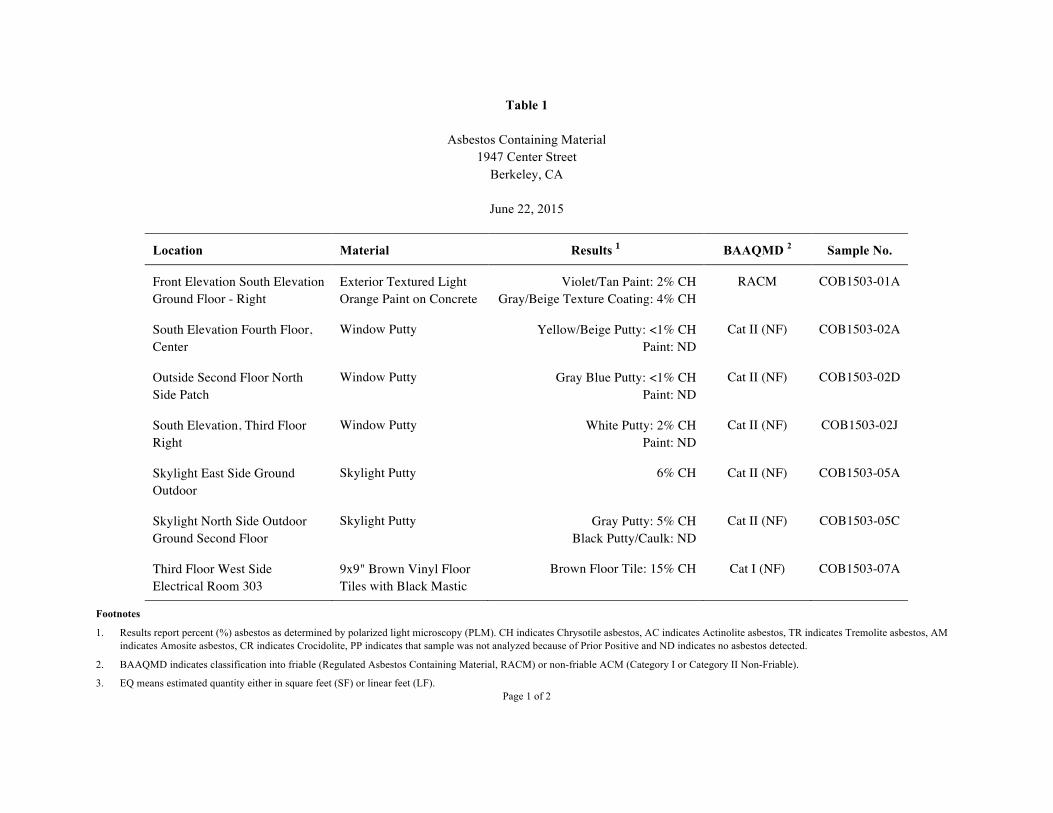
Table 1
Asbestos Containing Material 1947 Center Street
Berkeley, CA
June 22, 2015
Location Material Results 1 BAAQMD 2 Sample No.
Front Elevation South Elevation Ground Floor - Right
Exterior Textured Light Orange Paint on Concrete
Violet/Tan Paint: 2% CH Gray/Beige Texture Coating: 4% CH
RACM COB1503-01A
South Elevation Fourth Floor, Center
Window Putty Yellow/Beige Putty: <1% CH Paint: ND
Cat II (NF) COB1503-02A
Outside Second Floor North Side Patch
Window Putty Gray Blue Putty: <1% CH Paint: ND
Cat II (NF) COB1503-02D
South Elevation, Third Floor Right
Window Putty White Putty: 2% CH Paint: ND
Cat II (NF) COB1503-02J
Skylight East Side Ground Outdoor
Skylight Putty 6% CH Cat II (NF) COB1503-05A
Skylight North Side Outdoor Ground Second Floor
Skylight Putty Gray Putty: 5% CH Black Putty/Caulk: ND
Cat II (NF) COB1503-05C
Third Floor West Side Electrical Room 303
9x9" Brown Vinyl Floor Tiles with Black Mastic
Brown Floor Tile: 15% CH Cat I (NF) COB1503-07A
Footnotes
1. Results report percent (%) asbestos as determined by polarized light microscopy (PLM). CH indicates Chrysotile asbestos, AC indicates Actinolite asbestos, TR indicates Tremolite asbestos, AM indicates Amosite asbestos, CR indicates Crocidolite, PP indicates that sample was not analyzed because of Prior Positive and ND indicates no asbestos detected.
2. BAAQMD indicates classification into friable (Regulated Asbestos Containing Material, RACM) or non-friable ACM (Category I or Category II Non-Friable).
3. EQ means estimated quantity either in square feet (SF) or linear feet (LF). Page 1 of 2

Table 1(continued)
Asbestos Containing Material 1947 Center Street
Berkeley, CA
June 22, 2015
Location Material Results 1 BAAQMD 2 Sample No.
Floor Tile Under Carpet South Side Third Floor
9x9" Brown Vinyl Floor Tiles with Black Mastic
Tan Floor Tile: 3% CH Cat I (NF) COB1503-07B
Carpet, Fourth Floor Southeast Side
9x9" Brown Vinyl Floor Tiles with Black Mastic
Brown Floor Tile: 15% CH Yellow Carpet Mastic: ND
Cat I (NF) COB1503-07C
Footnotes
1. Results report percent (%) asbestos as determined by polarized light microscopy (PLM). CH indicates Chrysotile asbestos, AC indicates Actinolite asbestos, TR indicates Tremolite asbestos, AM indicates Amosite asbestos, CR indicates Crocidolite, PP indicates that sample was not analyzed because of Prior Positive and ND indicates no asbestos detected.
2. BAAQMD indicates classification into friable (Regulated Asbestos Containing Material, RACM) or non-friable ACM (Category I or Category II Non-Friable).
3. EQ means estimated quantity either in square feet (SF) or linear feet (LF).
Page 2 of 2

Table 2
Non-Asbestos Containing Materials 1947 Center Street
Berkeley, CA
June 22, 2015
Location Material Results 1 Sample No.
West Elevation on Ground Floor Left
Exterior Textured Light Orange Paint on Concrete
White Paint : ND Gray Texture Coating : ND
Concrete: ND
COB1503-01B
Skylight North Center Elevation Exterior Textured Light Orange Paint on Concrete
White Paint: ND Gray Texture Coating: ND
Concrete: ND
COB1503-01C
East Elevation Outdoor, Second Floor
Exterior Textured Light Orange Paint on Concrete
White Paint: ND Gray Texture Coating: ND
Concrete: ND
COB1503-01D
West Elevation Second Floor Window
Exterior Textured Light Orange Paint on Concrete
White Paint: ND Gray Texture Coating: ND
COB1503-01E
North Elevation Parapet Exterior Textured Light Orange Paint on Concrete
White Paint: ND Gray Texture Coating : ND
Concrete: ND
COB1503-01F
East Side Fourth Floor Window Outside
Exterior Textured Light Orange Paint on Concrete
White Paint: ND Gray Texture Coating: ND
Concrete: ND
COB1503-01G
South Side, Center First Floor Window Putty White/Gray Putty: ND Paint: ND
COB1503-02B
Sky Light, North Side Elevation (Center) Second Floor
Window Putty White/Gray Putty: ND Paint: ND
COB1503-02C
East Elevation Second Floor Window Putty White/Gray Putty: ND Paint: ND
COB1503-02E
Skylight Window Second Floor North Side Elevation
Window Putty White/Gray Putty: ND Paint: ND
COB1503-02F
West Elevation, Second Floor Window
Window Putty White/Gray Putty: ND Paint: ND
COB1503-02G
Footnote
1. Samples were analyzed by polarized light microscopy and reported as not containing detectable amounts of asbestos. ND indicates that asbestos was not detected.
Page 1 of 3
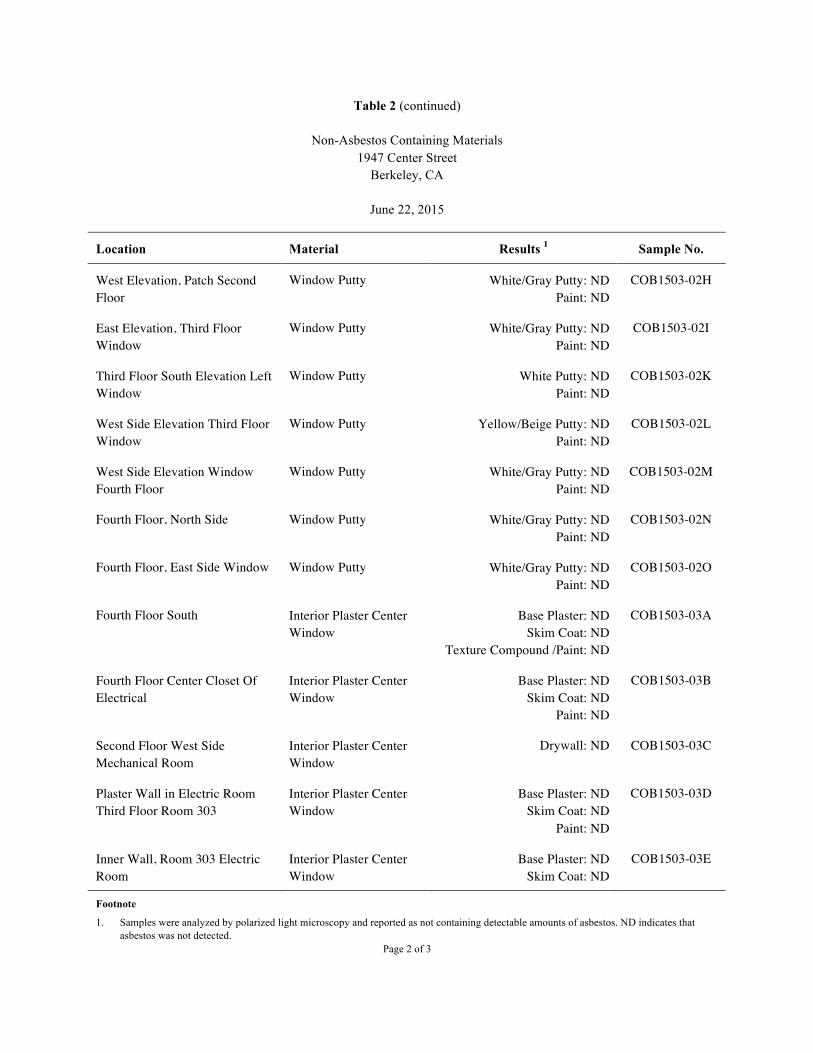
Table 2 (continued)
Non-Asbestos Containing Materials 1947 Center Street
Berkeley, CA
June 22, 2015
Location Material Results 1 Sample No.
West Elevation, Patch Second Floor
Window Putty White/Gray Putty: ND Paint: ND
COB1503-02H
East Elevation, Third Floor Window
Window Putty White/Gray Putty: ND Paint: ND
COB1503-02I
Third Floor South Elevation Left Window
Window Putty White Putty: ND Paint: ND
COB1503-02K
West Side Elevation Third Floor Window
Window Putty Yellow/Beige Putty: ND Paint: ND
COB1503-02L
West Side Elevation Window Fourth Floor
Window Putty White/Gray Putty: ND Paint: ND
COB1503-02M
Fourth Floor, North Side Window Putty White/Gray Putty: ND Paint: ND
COB1503-02N
Fourth Floor, East Side Window Window Putty White/Gray Putty: ND Paint: ND
COB1503-02O
Fourth Floor South Interior Plaster Center Window
Base Plaster: ND Skim Coat: ND
Texture Compound /Paint: ND
COB1503-03A
Fourth Floor Center Closet Of Electrical
Interior Plaster Center Window
Base Plaster: ND Skim Coat: ND
Paint: ND
COB1503-03B
Second Floor West Side Mechanical Room
Interior Plaster Center Window
Drywall: ND COB1503-03C
Plaster Wall in Electric Room Third Floor Room 303
Interior Plaster Center Window
Base Plaster: ND Skim Coat: ND
Paint: ND
COB1503-03D
Inner Wall, Room 303 Electric Room
Interior Plaster Center Window
Base Plaster: ND Skim Coat: ND
COB1503-03E
Footnote
1. Samples were analyzed by polarized light microscopy and reported as not containing detectable amounts of asbestos. ND indicates that asbestos was not detected.
Page 2 of 3

Table 2 (continued)
Non-Asbestos Containing Materials 1947 Center Street
Berkeley, CA
June 22, 2015
Location Material Results 1 Sample No.
Mechanical Room 322 The Wall Interior Plaster Center Window
Base Plaster: ND Skim Coat: ND
Paint: ND
COB1503-03F
Fourth Floor Women's Bathroom Wall
Interior Plaster Center Window
Base Plaster: ND Skim Coat: ND Adhesive: ND
COB1503-03G
Basement, Ster. Room 009 Lab Interior Debris Plaster: ND Skim Coat: ND
COB1503-04A
Basement, Ster. Room 009 Interior Debris Sheetrock: ND Compound: ND
COB1503-04A
Skylight North Side Outdoor Ground
Skylight Putty ND COB1503-05B
West Elevation Second Floor Duct Duct Seam, Tape Glue Tape / Glue: ND COB1503-06A
West Elevation Second Floor Duct Duct Seam, Tape Glue Tape / Glue: ND COB1503-06B
West Elevation Second Floor Duct Duct Seam, Tape Glue Tape / Glue: ND COB1503-06C
Mechanical Room 322 Linoleum Floor Third Floor
Yellow Vinyl Sheet Flooring
Vinyl Sheet Flooring: ND Backing / Mastic: ND
COB1503-08A
Janitor's Room, Fourth Floor in The Wall
Drywall Taping Mud Drywall: ND Taping Mud: ND
Paint: ND
COB1503-09A
Fourth Floor East Side Mechanical Room
Drywall Taping Mud Drywall: ND Taping Mud: ND Tape / Paint: ND
COB1503-09B
First Floor South Side Center Wall Drywall Taping Mud Drywall: ND Taping Mud: ND Tape / Paint: ND
COB1503-09C
Footnote
1. Samples were analyzed by polarized light microscopy and reported as not containing detectable amounts of asbestos. ND indicates that asbestos was not detected.
Page 3 of 3

Appendix A
Laboratory Reports
1947 Center Street Berkeley, CA
June 22, 2015
Acumen Project No. COB 1503
Prepared For:
City of Berkeley Public Works Department
1326 Allston Way, Berkeley Berkeley, CA 94702

Page 1 of 9
MICRO ANALYTICAL LABORATORIES, INC. BULK ASBESTOS ANALYSIS - POLARIZED LIGHT MICROSCOPY (PLM)
1092 Paul Spillane Acumen Industrial Hygiene, Inc. 1032 Irving Street, #922 San Francisco, CA 94122-2216
SAMPLE IDENTIFICATION
Client#: I COB1503-01 A
Micro #: 207373-01 Analyst: GR
EXTERIOR TEXTURED LIGHT ORANGE PAINT ON CONCRETE FRONT ELEVATION (SOUTH ELEVATION) GROUND FLOOR - RIGHT
Client# i COB1503-01 B
Micro # 207373-02 Analyst: GR
EXTERIOR TEXTURED LIGHT ORANGE PAINT ON CONCRETE WEST ELEVATION ON GROUND FLOOR LEFT
Client# ! COB1503-01 C
Micro # 207373-03 Analyst: GR
PROJECT:
PROJECT NO. COB1503 1947 CENTER STREET
BERKELEY,CA
ASBESTOS INFORMATION QUANTITY (AREA %) / TYPES / LAYERS / DISTINCT SAMPLES
PAINT (VIOLET /TAN): 2% CHRYSOTILE ASBESTOS
Micro Log In 207373 Total Samples 44
Date Sampled 0612212015
Date Received 06122/2015
Date Analyzed 06122/2015
DOMINANT OTHER MATERIALS
TEXTURE COATING (GRAY / BEIGE): 4% CHRYSOTILE ASBESTOS
NFM ROCK FRAGMENTS. CARBONATE, B!NDER
PAINT (WHITE): NONE DETECTED TEXTURE COATING (GRAY): NONE DETECTED CONCRETE: NONE DETECTED NFM ROCK FRAGMENTS, CARBONATE,
BINDER
PAINT (WHITE): NONE DETECTED
,
, I , I
EXTERIOR TEXTURED LIGHT TEXTURE COATING (GRAY): NONE DETECTED I ORANGE PAINT ON CONCRETE CONCRETE: NONE DETECTED NFM:
I ROCK FRAGMENTS, CARBONATE, ,
SKYLIGHT NORTH CENTER ELEVATION B!NDER
Client#: i COB1503-01 D
I Micro # 207373-04 Analyst GR PAINT (WHITE): NONE DETECTED , TEXTURE COATING (GRAY): NONE DETECTED i
I EXTERIOR TEXTURED LIGHT ORANGE PAINT ON CONCRETE CONCRETE: NONE DETECTED !
NFM: ROCK FRAGMENTS, CARBONATE, I
EAST ELEVATION OUTDOOR, 2ND FLOOR BINDER I
Client# i COB1503-01 E
Micro # 207373-05 Analyst: GR PAINT (WHITE): NONE DETECTED
EXTERIOR TEXTURED LIGHT TEXTURE COATING (GRAY): NONE DETECTED ,
ORANGE PAINT ON CONCRETE NFM: ROCK FRAGMENTS, CARBONATE, I WEST ELEVATION 2ND FLOOR WINDOW BINDER i
I
Technical Supervisor;,~ .-.""",,-
6/2312015 Date Reported
NVLAP Lab Code 101872-0. CA ELAP Certification #1037. Analyses use Polarize light Micr1scopy (PLM), Micro Analytical SOP PLM-l0l Basic techniques follow the EPA Interim Method for Bulk Insulation Samples (1982), and EPA-600/R93-116 (1993). The 1993 meth6d covers all types of bulk materials and is based on the 1982 Method, with improved analytical techniques for layered samples as required for NESHAP compliance. Asbestos is quantified by calibrated visual estimation. Detection limit is material dependent. Detection of asbestos traces (much less than 1%) may not be reliable or reproducible by PLM. Weight % cannot be determined by PLM. Asbestos with diameter below -1 flm may not be detected by PLM. Absence of asbestos in dust, debriS, and some compact materials, including fioor tiles, cannot be conclusively establiShed by PLM, and should be confirmed by Transmission Electron Microscopy (TEM).lnterferences may prevent detection of small asbestos fibers, and hinder determination of some optical properties,Tremolite-asbestos or actinolite- asbestos may be indistinguishable by PLM from some similar, non-regulated amphiboles (e.g. the "Libby Amphiboles" richterite and winchltel, and should be confinmed by TEM. The lower quantltation limit (reporting limit) of PLM estimation is 1%. The Cal-OSHA definition of asbestos-containing construction material is 0.1 Vo asbestos; however, reliable determination of asbestos percent at this level cannot be done by PLM estimation; PLM Point Counting or TEM weight percent analysis are recommended. Only aominant non-asbestos materials (fibrous and non-fibrous) are listed. This analysis shall not be construed as conclusive for any reported materials other than asbestos. Sample heterogeneity is indicated by listing more than one distinct layer or material on the report, If more than one distinct sample is received in the same container, samples shall be marked with letters and analyzed separately. Layers within a sample are analyzed se8arately when feasible; if asbestos is detected, percentages are reported for individual layers. Interlayer contamination is possible among any layers in a sample. The notation NO (or 'NONE DETECTED") indicates a result of "NO ASBESTOS DETECTED" in a homogeneous sample, or in all layers of a heterogeneous sample. Composite asbestos percentages from multiple layers are applicable only to wallboard I joint compound systems; compositing is based on customers' descriptions of material as "joint compound". Customers are solely responSible for identification and description of bulk matenals listed on field forms. Laboratory descriptions may differ from those given by customers, Quality Control (QC): all results have been determined to be within acceptance limits prior to reporting, Samples that were reanalyzed are denoted by two sets of analyst initials. Unless otherwise stated herein, all samples were received in accertable condition for analysis, This report must not be used to claim product endorsement by NIST or any U.S. Government agency. This report shall not be reproduced except in ful , without the approval of Micro Analytical Laboratories, Inc., and pertains only to the samples analyzed. NFM = Non-fibrous materials.
5900 HOLLIS STREET, SUITE M - EMERYVILLE, CA 94608 - (510) 653-0824

Page 2 of 9
MICRO ANALYTICAL LABORATORIES, INC. BULK ASBESTOS ANALYSIS - POLARIZED LIGHT MICROSCOPY (PLM)
1092 Paul Spillane Acumen Industrial Hygiene, Inc, 1032 Irving Street, #922 San Francisco, CA 94122-2216
SAMPLE IDENTIFICATION
,--! Client#: , COB1503-01 F
Micro # 207373-06 Analyst: GR
EXTERIOR TEXTURED LIGHT ORANGE PAINT ON CONCRETE NORTH ELEVATION PARAPET
Client# ! COB1503-01 G
Micro # 207373-07 Analyst: GR
EXTERIOR TEXTURED LIGHT ORANGE PAINT ON CONCRETE EAST SIDE 4TH FLOOR WINDOW OUTSIDE
Client # L COB1503-02A .. _._---_ .. _--
Micro # 207373-08 Analyst: GR
WINDOWPUTIY LIGHT ORANGE PAINT ON CONCRETE SOUTH ELEVATION FOURTH FLOOR, CENTER
Client# I COB1503-02B -
Micro # 207373-09 Analyst: GR
WINDOWPUTIY LIGHT ORANGE PAINT ON CONCRETE SOUTH SIDE, CENTER 1ST FLOOR
Client# I COB1503-02C
I Micro #: 207373-10 Analyst: GR
WINDOWPUTIY LIGHT ORANGE PAINT ON CONCRETE SKY LIGHT, NORTH SIDE ELEVATION (CENTER) 2ND FLOOR
PROJECT:
PROJECT NO. COB1503 1947 CENTER STREET
BERKELEY, CA
ASBESTOS INFORMATION QUANTITY (AREA %) I TYPES I LAYERS I DISTINCT SAMPLES
PAINT (WHITE): NONE DETECTED TEXTURE COATING (GRAY): NONE DETECTED
CONCRETE: NONE DETECTED
PAINT (WHITE): NONE DETECTED TEXTURE COATING (GRA Y): NONE DETECTED
CONCRETE: NONE DETECTED
PUTTY (YELLOW I BEIGE): < 1% CHRYSOTILE ASBESTOS
PAINT: NONE DETECTED
PUTTY (WHITE I GRA Y): NONE DETECTED PAINT: NONE DETECTED
PUTTY (WHITE I GRA Y): NONE DETECTED
PAINT: NONE DETECTED
Technical Supervisor: 612312015 ....:::. cO ---Gam! Date Reported
Micro Log In 207373 Total Samples 44
Date Sampled
Date Received
06/2212015
0612212015
06122/2015 Date Analyzed
NFM
NFM
NFM
NFM'
NFM.
DOMINANT OTHER MATERIALS
ROCK FRAGMENTS, CARBONATE, BINDER
ROCK FRAGMENTS, CARBONATE, BINDER
SYNTHETIC MATERIAL, CARBONATE
SYNTHETIC MATERIAL, CARBONATE.
SYNTHETIC MATERIAL, CARBONATE.
I
/ NVLAP Lab Code 101872-0. CA ELAP Certification #1037. Analyses use Polarized Light MiCros&'Py (PLM), Micro Analytical SOP PLM-1 01, Basic techniques follow the EPA Interim Method for Bulk Insulation Samples (1982), and EPA-600/R93-116 (1993). The 1993 method covers all types of bulk materials and is based on the 1982 Method, with improved analytical techniques for layered samples as required for NESHAP compliance, Asbestos is quantified by calibrated visual estimation. Detection limit is material dependent. Detection of asbestos traces (much less than 1 %) may not be reliable or reproducible by PLM, Weight % cannot be determined by PLM. Asbestos with diameter below -1 ftm may not be detected by PLM, Absence of asbestos in dust, debris, and some compact materials, including floor tiles, cannot be conclusively established by PLM, and should be confirmed by Transmission Electron Microscopy (TEM).lnterferences may prevent detection of small asbestos fibers, and hinder determination of some optical properties.Tremolite-asbestos or actinolite- asbestos may be indistinguishable by PLM from some similar, non-regulated amphiboles (e.g. the "Libby Amphiboles" richterite and winchlteb' and should be confirmed by TEM. The lower quantltation limit (reporting limit) of PLM estimation is 1%. The Cal-OSHA definition of asbestos-containing construction material is 0,1 Vo asbestos; howeve," reliable determination of asbestos percent at this level cannot be done by PLM estimation; PLM Point Counting or TEM weight percent analysis are recommended, Only aominant non-asbestos materials (fibrous and non-fibrous) are listed. This analysis shall not be construed as conclusive for any reported materials other than asbestos. Sample heterogeneity is indicated by listing more than one distinct layer or material on the report. If more than one distinct sample is received in the same container, samples shall be marked with letters and analyzed separately, Layers Within a sample are analyzed ser,arately when feaSible; If asbestos IS detected, percentages are reported for individual layers, Interlayer contamination IS possible among any layers in a sample. The notation ND (or 'NONE DETECTED") indicates a result of "NO ASBESTOS DETECTED" In a homogeneous sample, or in all layers of a heterogeneous sample. Composite asbestos percentages from multiple laxers are applicable only to wallboard I joint compound systems; compositing is based on customers' descriptions of material as "joint compound". Customers are solely responSible for identification and description of bulk matenals listed on field forms, Laboratory descriptions may differ from those given by customers. Quality Control (QC): all results have been determined to be within acceptance limits prior to reporting. Samples that were reanalyzed are denoted by two sets of analyst initials. Unless othelWise stated herein, all samples were received in acceptable condition for analysis. This report must not be used to claim product endorsement by NIST or any U.S. Government agency: This report shall not be reproduced except in full, without the approval of Micro Analytical Laboratories, Inc., and pertains only to the samples analyzed. NFM = Non-fibrous matenals,
5900 HOLLIS STREET, SUITE M - EMERYVILLE, CA 94608 - (510) 653-0824

Page 3 of 9
MICRO ANALYTICAL LABORATORIES, INC. BULK ASBESTOS ANALYSIS - POLARIZED LIGHT MICROSCOPY (PLM)
1092 Paul Spillane Acumen Industrial Hygiene, Inc. 1032 Irving Street, #922 San Francisco, CA 94122-2216
SAMPLE IDENTIFICATION
1~1i,"" I COB1SO,·020 Micro # 207373-11 Analyst: GR
WINDOW PUTTY , OUTSIDE 2ND FLOOR
NORTH SIDE PATCH
Client# I COB1503-02E
Micro # 207373-12 Analyst: GR
WINDOW PUTTY EAST ELEVATION 2ND FLOOR
Client# I COB1503-02F
GR
------------------- '--Micro # 207373-13 Analyst: GR
WINDOW PUTTY SKYLIGHT WINDOW 2ND FLOOR NORTH SIDE ELEVATION
Client#: i COB1503-02G
Micro # 207373-14 Analyst: GR
WINDOW PUTTY WEST ELEVATION, 2ND FLOOR WINDOW
Client# L_ COB1503-02H
Micro # 207373-15 Analyst: GR
WINDOW PUTTY WEST ELEVATION, PATCH 2ND FLOOR
PROJECT:
PROJECT NO. COB1503 1947 CENTER STREET
BERKELEY, CA
ASBESTOS INFORMATION QUANTITY (AREA %) I TYPES I LAYERS I DISTINCT SAMPLES
PUTTY (GRAY BLUE): < 1 % CHRYSOTILE ASBESTOS PAINT: NONE DETECTED
PUTTY (WHITE I GRAY): NONE DETECTED PAINT: NONE DETECTED
PUTTY (WHITE I GRA Y): NONE DETECTED
PAINT: NONE DETECTED
PUTTY (WHITE I GRAY): NONE DETECTED PAINT: NONE DETECTED
PUTTY (WHITE I GRAY): NONE DETECTED PAINT: NONE DETECTED
6123/2015 Date Reported
,
Micro Log In 207373 Total Samples 44
Date Sampled
Date Received
06/22/2015
06/22/2015
06/22/2015 Date Analyzed
NFM
NFM
NFM
NFM
NFM
DOMINANT OTHER MATERIALS
SYNTHETIC MATERIAL, CARBONATE
SYNTHETIC MATERIAL, CARBONATE.
SYNTHETIC MATERIAL. CARBONATE
SYNTHETIC MATERIAL, CARBONATE
SYNTHETIC MATERIAL, CARBONATE.
I
NVLAP Lab Code 101872-0. CA ELAP Certification #1037. Analyses use Polarized Light Microscopy (PLM), Micro Analytical SOP PLM-1 01. Basic techniques follow the EPA Interim Method for Bulk Insulation Samples (1982), and EPA-600/R93-116 (1993). The 1993 method covers all types of bulk materials and is based on the 1982 Method, with improved analytical techniques for layered samples as required for NESHAP compliance. Asbestos is quantified by calibrated visual estimation. Detection limit is material dependent. Detection of asbestos traces (much less than 1%) may not be reliable or reproducible by PLM. Weight % cannot be determined by PLM. Asbestos with diameter below -1 flm may not be detected by PLM. Absence of asbestos in dust, debris, and some compact materials, including fioor tiles, cannot be conclusively established by PLM, and should be confmmed by TransmiSSion Electron Microscopy (TEM).lnterterences may prevent detection of small asbestos fibers, and hinder determination of some optical properties.Tremolite-asbestos or actinolite- asbestos may be indistinguishable by PLM from some similar, non-regulated amphiboles (e.g. the "Libby Amphiboles" richterite and winchlte£, and should be confinmed by TEM. The lower quantltation limit (reporting limit) of PLM estimation is 1%. The Cal-OSHA definition of asbestos-containing construction material is 0.1 y, asbestos; however
d reliable
determination of asbestos percent at this level cannot be done by PLM estimation; PLM Paint Counting or TEM weight percent analysiS are recommended. Only ominant non-asbestos materials (fibrous and non-fibrous) are listed. This analysis shall not be construed as conclusive for any reported materials other than asbestos. Sample heterogeneity is indicated by listing more than one distinct layer or material on the report. If more than one distinct sample is received in the same container, samples shall be marked with le1ters and analyzed separately. Layers within a sample are analyzed se~arately when feasible; if asbestos is detected, percentages are reported for individual layers. Interlayer contamination is possible among any layers in a sample. The notation ND (or 'NONE DETECTED") indicates a result of "NO ASBESTOS DETECTED" in a homogeneous sample, or in all layers of a heterogeneous sample. CompOSite asbestos percentages from multiple layers are applicable only to wallboard I joint compound systems; compositing is based on customers' descriptions of material as "joint compound". Customers are solely responSible for identification and description of bulk matenals listed on field forms. Laboratory descriptions may differ from those given by customers. Quality Control (QC): all results have been determined to be within acceptance limits prior to reporting. Samples that were reanalyzed are denoted by two sets of analyst initials. Unless otherwise stated herein, all samples were received in acceFtable condition for analysis. This report must not be used to claim product endorsement by NIST or any U.S. Government agency, This report shall not be reproduced except in ful , without the approval of Micro Analylical Laboratories, Inc., and pertains only to the samples analyzed. NFM = Non-fibrous matenals.
5900 HOLLIS STREET, SUITE M - EMERYVILLE, CA 94608 - (510) 653-0824

,
Page 4 of 9
MICRO ANALYTICAL LABORATORIES, INC. BULK ASBESTOS ANALYSIS - POLARIZED LIGHT MICROSCOPY (PLM)
1092 Paul Spillane Acumen Industrial Hygiene, Inc, 1032 Irving Street, #922 San Francisco, CA 94122-2216
SAMPLE IDENTIFICATION
I~"ot' COB1503-021
MIcro # 207373-16 Analyst: GR
WINDOW PUTTY EAST ELEVATION, 3RD FLOOR WINDOW
I I Client # i COB1503-02J
I Micro # 207373-17 Analyst: GR
WINDOW PUTTY SOUTH ELEVATION, 3D FLOOR (RIGHn
GR
Client # I COB1503-02K L ___ ~_._~~ ___ ~._~. ___ ~._
Micro # 207373-18 Analyst: GR GR
WINDOW PUTTY SOUTH ELEVATION LEFT WINDOW 3RD FLOOR
Client#: I COB1503-02L
Micro #: 207373-19 Analyst: GR GR
WINDOW PUTTY WEST SIDE ELEVATION 3RD FLOOR WINDOW
Client#: i COB1503-02M
Micro # 207373-20 Analyst: GR
WINDOW PUTTY WEST SIDE ELEVATION WINDOW 4TH FLOOR
PROJECT:
PROJECT NO. COB1503 1947 CENTER STREET
BERKELEY,CA
ASBESTOS INFORMATION QUANTITY (AREA %) I TYPES I LAYERS I DISTINCT SAMPLES
PUTTY (WHITE I GRA Y): NONE DETECTED PAINT: NONE DETECTED
PUTTY (WHITE): 2% CHRYSOTILE ASBESTOS PAINT: NONE DETECTED
PUTTY (WHITE): NONE DETECTED PAINT: NONE DETECTED
PUTTY (YELLOW I BEIGE): NONE DETECTED PAINT: NONE DETECTED
PUTTY (WHITE I GRA Y): NONE DETECTED PAINT: NONE DETECTED
Technical Supervi~()D~ 6/24/2015 Date Reported
Micro Log In 207373 Total Samples 44
Date Sampled
Date Received
06122/2015
06/2212015
06122/2015 Date Analyzed
NFM
NFM:
NFM:
NFM:
NFM
DOMINANT OTHER MATERIALS
SYNTHETIC MATERIAL, CARBONATE
SYNTHETIC MATERIAL, CARBONATE.
SYNTHETIC MATERIAL, CARBONATE
SYNTHETIC MATERIAL, CARBONATE.
SYNTHETIC MATERIAL, CARBONATE
;
NVLAP Lab Code 101872·0. CA ELAP Certification #1037. Analyses use Polarize1(Ught Microscopy (PLM), Micro Analytical SOP PLM,1 01. Basic techniques follow the EPA Interim Method for Bulk Insulation Samples (1982), and EPA·600/R93-116 (1993). The 1993 method covers all types of bulk materials and IS based on the 1982 Method, with improved analytical techniques for layered samples as required for NESHAP compliance. Asbestos is quantified by calibrated visual estimation. Detection limit is material dependent. Detection of asbestos traces (much less than 1%) may not be reliable or reproducible by PLM. Weight % cannot be determined by PLM. Asbestos with diameter below -1 ftm may not be detected by PLM. Absence of asbestos in dust, debris, and some compact materials, including floor tiles, cannot be conClusively established by PLM, and should be confirmed by Transmission Electron Microscopy (TEM).lnterferences may prevent detection of small asbestos fibers, and hinder determination of some optical properties.Tremolite-asbestos or actinolite- asbestos may be indistinguishable by PLM from some similar, non·regulated amphiboles (e.g. the "Libby Amphiboles" richterite and winchlte!, and should be confirmed by TEM. The lower quantrration limit (reporting limit) of PLM estimation is 1 %. The Cal-OSHA definition of asbestos-containing construction material is 0.1 y, asbestos; however, reliable determination of asbestos percent at this lever cannot be done by PLM estimation; PLM Point Counting or TEM weight percent analysis are recommended. Only dominant non-asbestos materials (fibrous and non-fibrous) are listed. This analysis shall not be construed as conclusive for any reported materials other than asbestos. Sample heterogeneity is indicated by listing more than one distinct layer or material on the report. If more than one distinct sample is received in the same container, samples shall be marked with letters and analyzed separately. Layers within a sample are analyzed se8arately when feasible; if asbestos is detecte'!., percentages are reported for individual layers. Interlayer contamination is possible among any layers in a sample. The notation ND (or 'NONE DETECTED") indicates a result of "Nu ASBESTOS DETECTED" in a homogeneous sample, or in all layers of a heterogeneous sample. Composite asbestos percentages from multiple layers are applicable only to wallboard I joint compound systems; compositing is based on customers' descriptions of material as "joint compound". Customers are solely responsible for identification and description of bulk matenals listed on field forms. Laboratory descriptions may differ from those given by customers. Ouality Control (OC): all results have been determined to be within acceptance limits prior to reporting. Samples that were reanalyzed are denoted by two sets of analyst initials. Unless otherwise stated herein, all samples were received in acceptable condition for analysis. This report must not be used to claim product endorsement by NIST or any U.S. Government agency. This report shall not be reproduced except in ful , without the approval of Micro Analytical Laboratories, Inc., and pertains only to the samples analyzed. NFM = Non·fibrous materials.
5900 HOLLIS STREET, SUITE M - EMERYVILLE, CA 94608 - (510) 653-0824
I

Page 5 of 9
MICRO ANALYTICAL LABORATORIES, INC. BULK ASBESTOS ANALYSIS - POLARIZED LIGHT MICROSCOPY (PLM)
1092 Paul Spillane Acumen Industrial Hygiene, Inc, 1032 Irving Street, #922 San Francisco, CA 94122-2216
SAMPLE IDENTIFICATION
PROJECT:
PROJECT NO. COB1503 1947 CENTER STREET
BERKELEY, CA
ASBESTOS INFORMATION QUANTITY (AREA %) I TYPES I LAYERS I DISTINCT SAMPLES
Micro Log In
Total Samples
Date Sampled
Date Received
Date Analyzed
207373 44
06/2212015
06/22/2015
0612212015
DOMINANT OTHER MATERIALS
IClient# ! COB1503-02N
Micro # 207373-21 Analyst: GR PUTTY (WHITE I GRA Y): NONE DETECTED
WINDOW PUTTY PAINT: NONE DETECTED
4TH FLOOR, NORTH SIDE NFM SYNTHETIC MATERIAL, CARBONATE,
Client#: I COB1503-020
Micro #: 207373-22 Analyst: GR PUTTY (WHITE I GRA Y): NONE DETECTED
WINDOW PUTTY PAINT: NONE DETECTED
I 4TH FLOOR, EAST SIDE WINDOW NFM: SYNTHETIC MATERIAL,
I CARBONATE
Client # L COB1503-03A -----"-~-----"------ ... ".,,---_ .. ,,-
Micro # 207373-23 Analyst: GR BASE PLASTER: NONE DETECTED
INTERIOR PLASTER CENTER WINDOW SKIM COAT: NONE DETECTED
FOURTH FLOOR SOUTH TEXTURE COMPOUND I PAINT: NONE DETECTED NFM ROCK FRAGMENTS, CARBONATE, BINDER
Client# I COB1503-03B
Micro # 207373-24 Analyst: GR BASE PLASTER: NONE DETECTED
INTERIOR PLASTER CENTER WINDOW SKIM COAT: NONE DETECTED
FOURTH FLOOR CENTER CLOSET PAINT: NONE DETECTED NFM ROCK FRAGMENTS, CARBONATE, OF ELECTRICAL BINDER
I I
Client#: I COB1503-03C
Micro # 207373-25 Analyst: GR DRYWALL: NONE DETECTED
INTERIOR PLASTER CENTER WINDOW 2ND FLOOR WEST SIDE MECHANICAL ROOM NFM 'GYPSUM'(CALCIUM SULFATE)
(NO PLASTER IN THE SAMPLE)
......... · .. ···:c-r"'ua mi Ran tunga, Ph.D, f \
Date Reported
NVLAP Lab Code 101872-0. CA ELAP Certification #1037. Analyses use Polarized Light Micros60py (PLM), Micro Analytical SOP PLM·1 01. Basic techniques follow the EPA Interim Method for Bulk Insulation Samples (1982), and EPA-600/R93-116 (1993). The 1993 method covers all types of bulk materials and is based on the 1982 Method, with improved analytical techniques for layered samples as required for NESHAP compliance. Asbestos is quantified by calibrated visual estimation. Detection limit is material dependent. Detection of asbestos traces (much less than 1%) may not be reliable or reproducible by PLM. Weight % cannot be determined by PLM. Asbestos with diameter below -1 f'm may not be detected by PLM. Absence of asbestos in dust, debris, and some compact materials, including fioor tiles, cannot be conclusively established by PLM, and should be confirmed by Transmission Electron Microscopy (TEM).lnterferences may prevent detection of small asbestos fibers, and hinder determination of some optical properties,Tremolite-asbestos or actinolite· asbestos may be indistinguishable by PLM from some similar, non-regulated amphiboles (e.g. the "Libby Amphiboles" richterite and winchlteb, and should be confirmed by TEM. The lower quantltation limit (reporting limit) of PLM estimation is 1 %. The Cal-OSHA definition of asbestos-containing construction material is 0.1 y, asbestos; however
d reliable
determination of asbestos percent at this level cannot be done by PLM estimation; PLM Point Counting or TEM weight percent analysiS are recommended. Only ominant non-asbestos materials (fibrous and non-fibrous) are listed. This analysis shall not be construed as conclusive for any reported materials other than asbestos. Sample heterogeneity is indicated by listing more than one distinct layer or material on the report. If more than one distinct sample is received in the same container, samples shall be marked with lelters and analyzed separately. Layers within a sample are analyzed se8arately when feasible; if asbestos is detected, percentages are reported for individual layers. Interlayer contamination is possible among any layers in a sample. The notation NO (or 'NONE DETECTED") indicates a result of "NO ASBESTOS DETECTED" in a homogeneous sample, or in all layers of a heterogeneous sample. Composite asbestos percentages from multiple layers are applicable only to wallboard I joint compound systems; compositing is based on customers' descriptions of material as "joint compound". Customers are solely responSible for identification and description of bulk matenals listed on field forms. Laboratory descriptions may differ from those given by customers. Quality Control (QC): all results have been determined to be within acceptance limits prior to reporting, Samples that were reanalyzed are denoted by two sets of analyst initials. Unless otherwise stated herein, all samples were received in accertable condition for analysis. This report must not be used to claim product endorsement by NIST or any U.S. Government agency. This report shall not be reproduced except in ful , without the approval of Micro Analytical Laboratories, Inc., and pertains only to the samples analyzed. NFM = Non-fibrous materials.
5900 HOLLIS STREET, SUITE M - EMERYVILLE, CA 94608 - (510) 653-0824
I
I

Page 6 of 9
MICRO ANALYTICAL LABORATORIES, INC. BULK ASBESTOS ANALYSIS - POLARIZED LIGHT MICROSCOPY (PLM)
1092 Paul Spillane Acumen Industrial Hygiene, Inc. 1032 Irving Street, #922 San Francisco, CA 94122-2216
SAMPLE IDENTIFICATION
r~r L COB1503-6'O Micro # 207373-26 Analyst: BK
INTERIOR PLASTER CENTER WINDOW PLASTER WALL IN ELECTRIC
i ROOM 3RD FLOOR (ROOM 303)
i Client# I COB1503-03E
Micro # 207373-27 Analyst: BK
INTERIOR PLASTER CENTER WINDOW INNER WALL, ROOM 303 ELECTRIC ROOM
Client # l .. ___ ... COB150~:02."'..~ -~---~
Micro # 207373-28 Analyst: BK
INTERIOR PLASTER CENTER WINDOW MECHANICAL ROOM 322 THE WALL
Client# ! COB1503-03G I
Micro # 207373-29 Analyst: BK GR
INTERIOR PLASTER CENTER WINDOW I WOMEN'S BATHROOM WALL FOURTH FLOOR
I Client# : COB1503-04A
Micro # 207373-30A Analyst: BK
INTERIOR DEBRIS BASEMENT, STER. ROOM 009 LAB NOTE: PLASTER
L.... ______
PROJECT:
PROJECT NO. COB1503 1947 CENTER STREET
BERKELEY, CA
ASBESTOS INFORMATION QUANTITY (AREA %) I TYPES I LAYERS I DISTINCT SAMPLES
BASE PLASTER: NONE DETECTED SKIM COAT: NONE DETECTED PAINT: NONE DETECTED
BASE PLASTER: NONE DETECTED SKIM COAT: NONE DETECTED
BASE PLASTER: NONE DETECTED SKIM COAT: NONE DETECTED PAINT: NONE DETECTED
BASE PLASTER: NONE DETECTED SKIM COAT: NONE DETECTED ADHESIVE: NONE DETECTED
PLASTER: NONE DETECTED SKIM COAT: NONE DETECTED
Tech nical Su pervi~':::-':'-.",""=· .""= .... ~~~\--_-;--_""-;=;-~----r;-:-6;:-c/2'"3c::c/:-:2-:;:0-::-:;-1 5 L............. . amini R natunga, Ph.D. Date Reported
Micro Log In 207373 Total Samples 44
06/22/2015
06/22/2015
06/22/2015
Date Sampled
Date Received
Date Analyzed
NFM.
NFM.
NFM
NFM.
NFM
DOMINANT OTHER MATERIALS
ROCK FRAGMENTS. CARBONATE. BINDER
ROCK FRAGMENTS, CARBONATE, BINDER
ROCK FRAGMENTS. CARBONATE. BINDER
ROCK FRAGMENTS. CARBONATE. BINDER
ROCK FRAGMENTS. CARBONATE. BINDER
I
{ J NVLAP Lab Code 101872·0. CA ELAP Certification #1037. Analyses use Polariz~d Light Microscopy (PLM). Micro Analytical SOP PLM·101 Basic techniques follow the EPA Interim Method for Bulk Insulation Samples (1982). and EPA·600/R93·116 (1993). The 1993 method covers all types of bulk materials and is based on the 1982 Method, with improved analytical techniques for layered samples as required for NESHAP compliance. Asbestos is quantified by calibrated visual estimation. Detection limit is material dependent. Detection of asbestos traces (much less than 1%) may not be reliable or reproducible by PLM. Weight % cannot be determined by PLM. Asbestos with diameter below -1 ~m may not be detected by PLM. Absence of asbestos in dust, debris, and some compact materials, including floor tiles. cannot be conclusively established by PLM. and should be confirmed by Transmission Electron Microscopy (TEM).lnterferences may prevent detection of small asbestos fibers, and hinder determination of some optical properties.Tremolite·asbestos or actinolite· asbestos may be indistinguishable by PLM from some similar, non-regulated amphiboles (e.g. the "Libby Amphiboles" richterite and winchiteb, and should be confirmed by TEM. The lower quantltation limit (reporting limit) of PLM estimation is 1 %. The Cal-OSHA definition of asbestos·containing construction material is 0.1 Vo asbestos; however, reliable determination of asbestos percent al this level cannot be done by PLM estimation; PLM Point Counting or TEM weight percent analysis are recommended. Only dominant non-asbestos materials (fibrous and non·fibrous) are listed. This analYSis shall not be construed as conclusive for any reported materials other than asbestos. Sample heterogeneity is indicated by listing more than one distinct layer or material on the report. If more than one distinct sample is received in the same container, samples shall be marked with letters and analyzed separately. Layers within a sample are analyzed se8arately when feasible; if asbestos is detected. percentages are re~orted for individual layers. Interlayer contamination is possible among any layers in a sample. The notation ND (or 'NONE DETECTED") indicates a result of "NO ASBESTOS DETECTED" in a homogeneous sample, or in all layers of a heterogeneous sample. CompOSite asbestos percentages from multiple layers are applicable only to wallboard I joint compound systems; compositing is based on customers' descriptions of material as "joint compound". Customers are solely responSible for identification and description of bulk matenals listed on field forms. Laboratory descriptions may differ from those given by customers. Quality Control (QC): all results have been determined to be within acceptance limits prior to reporting. Samples that were reanalyzed are denoted by two sets of analyst initials Unless otherwise stated herein, all samples were received in acceptable condition for analysiS. This report must not be used to claim product endorsement by NIST or any U.S. Government agency. This report shall not be reproduced except in full, without the approval of Micro Analytical Laboratories, Inc., and pertains only to the samples analyzed. NFM ; Non·fibrous materials.
5900 HOLLIS STREET, SUITE M - EMERYVILLE, CA 94608 - (510) 653-0824
I I
I
I i I

Page 7 of 9
MICRO ANALYTICAL LABORATORIES, INC. I···A:!] r:.ru, [!]~
BULK ASBESTOS ANALYSIS - POLARIZED LIGHT MICROSCOPY (PLM)
1092 Paul Spillane Acumen Industrial Hygiene, Inc. 1032 Irving Street, #922 San Francisco, CA 94122-2216
SAMPLE IDENTIFICATION
IClien!#T COB1S03-04A
Micro # 207373-30B Analyst: BK
INTERIOR DEBRIS BASEMENT, STER. ROOM 009 LAB NOTE: SHEETROCK
Client# ! COB1S03-0SA
Micro # 207373-31 Analyst GR
SKYLIGHT PUTTY SKYLIGHT EAST SIDE GROUND OUTDOOR
Client # L ____ ~~~~~~-OSB I Micro # 207373-32 Analyst: GR
PROJECT: PROJECT NO. COB1503 1947 CENTER STREET
BERKELEY, CA
ASBESTOS INFORMAT~N QUANTITY (AREA %) I TYPES I LAYERS I DISTINCT SAMPLES
SHEETROCK: NONE DETECTED COMPOUND: NONE DETECTED
6% CHRYSOTILE ASBESTOS
NONE DETECTED
Micro Log In 207373 Total Samples 44
Date Sampled 06/22/2015
Date Received 0612212015
Date Analyzed 0612212015
DOMINANT OTHER MATERIALS
NFM 'GYPSUM (CALCIUM SULFATE). CARBONATE
3 % CELLULOSE
5 % WOLLASTONITE I
NFM: P/ilND'E"!t'ClfHfR, MISCELLANEOUS.
I SKYLIGHT PUTTY SKYLIGHT NORTH SIDE OUTDOOR GROUND NFM: BINDER, OTHER, MISCELLANEOUS. I
Client #: L. COB1S03-05C 3 % CELLULOSE
Micro # 207373-33 Analyst: GR PUTTY (GRAY): S% CHRYSOTILE ASBESTOS
SKYLIGHT PUTTY PUTTY / CAULK (BLACK): NONE DETECTED 5 % WOLLASTONITE I
SKYLIGHT NORTH SIDE OUTDOOR GROUND NFM P/ilND'E"!t'ClfHfR, MISCELLANEOUS. 2ND FLOOR
I
I Client# I COB1S03-06A
Micro # 207373-34 Analyst: GR TAPE / GLUE: NONE DETECTED
DUCT SEAM, TAPE GLUE
I WEST ELEVATION 2ND FLOOR DUCT NFM BINDER, OTHER, MISCELLANEOUS
! I
Technical Supervisoc::c::.:~· 6/23/2015 C~:_~·r::;-:·""··~~f~-=-+-c---r;T~-----rD;-::a7te::-;O;RC:Ce-=-p-::Cort:::Ce::-d:;-
NVLAP Lab Code 101872·0. CA ELAP Certification #1037. Analyses use Polarized Light Microscopy (PLM), Micro Analytical SOP PLM-101 Basic techniques follow the EPA Interim Method for Bulk Insulation Samples (1982), and EPA-600/R93-116 (1993). The 1993 method covers all types of bulk materials and is based on the 1982 Method, with improved analytical techniques for layered samples as required for NESHAP compliance. Asbestos is quantified by calibrated visual estimation. Detection limit is material dependent. Detection of asbestos traces (much less than 1 %) may not be reliable or reproducible by PLM, Weight % cannot be determined by PLM. Asbestos with diameter below -1 ~m may not be detected by PLM. Absence of asbestos in dust, debris, and some compact materials, including floor tiles, cannot be conclusively established by PLM, and should be confirmed by Transmission Electron Microscopy (TEM).lnterferences may prevent detection of small asbestos fibers, and hinder determination of some optical properties.Tremolite-asbestos or actinolite- asbestos may be indistinguishable by PLM from some similar, non-regulated amphiboles (e.g. the "Libby Amphiboles" richterite and winchltel, and should be confirmed by TEM. The lower quantltation limit (reporting limit) of PLM estimation is 1%. The Cal-OSHA definition of asbestos-containing construction material is 0.1 Yo asbestos; however, reliable determination of asbestos percent at thiS level cannot be done by PLM estimation; PLM Point Counting or TEM weight percent analysis are recommended. Only dominant non-asbestos materials (fibrous and non-fibrous) are listed. This analysis shall not be construed as conclusive for any reported materials other than asbestos, Sample heterogeneity is indicated by listing more than one distinct layer or material on the report. If more than one distinct sample is received in the same container, samples shall be marked with letters and analyzed separately. Layers within a sample are analyzed se8arately when feasible; if asbestos is detected, percentages are reported for individual layers. Interlayer contamination is possible among any layers in a sample. The notation NO (or 'NONE DETECTED") indicates a result of "NO ASBESTOS DETECTED" in a homogeneous sample, or in all layers of a heterogeneous sample. CompOSite asbestos percentages from multiple layers are applicable only to wallboard I joint compound systems; compositing is based on customers' descriptions of material as "joint compound". Customers are solely responSible for identification and description of bulk matenals listed on field forms. Laboratory descriptions may differ from those given by customers. Quality Control (QC): all results have been determined to be within acceptance limits prior to reporting. Samples that were reanalyzed are denoted by two sets of analyst initials. Unless otherwise stated herein, all samples were received in accer.table condition for analysiS. This report must not be used to claim product endorsement by NIST or any U.S. Government agency. This report shall not be reproduced except in ful, without the approval of Micro Analytical Laboratories, Inc., and pertains only to the samples analyzed. NFM = Non-fibrous materials.
5900 HOLLIS STREET, SUITE M - EMERYVILLE, CA 94608 - (510) 653-0824

Page 8 of 9
MICRO ANALYTICAL LABORATORIES, INC. BULK ASBESTOS ANALYSIS - POLARIZED LIGHT MICROSCOPY (PLM)
1092 Paul Spillane Acumen Industrial Hygiene, Inc. 1032 Irving Street, #922 San Francisco, CA 94122-2216
SAMPLE IDENTIFICATION
IClient# I COB1503-06B
Micro # 207373-35 Analyst: GR DUCT SEAM. TAPE GLUE WEST ELEVATION 2ND FLOOR DUCT
Client# : COB1503-06C
Micro # 207373-36 Analyst: GR DUCT SEAM, TAPE GLUE WEST ELEVATION 2ND FLOOR DUCT
Client# : COB1503-07A L ____
--.-~-.-- --"---.-~------,~--- " .. ~ .. ~~-.~-
PROJECT:
PROJECT NO. COB1503 1947 CENTER STREET
BERKELEY, CA
ASBESTOS INFORMATION QUANTITY (AREA %) / TYPES / LAYERS / DISTINCT SAMPLES
TAPE / GLUE: NONE DETECTED
TAPE / GLUE: NONE DETECTED
Micro Log In
Total Samples
Date Sampled
Date Received
Date Analyzed
207373 44
06/22/2015
06/22/2015
0612212015
DOMINANT OTHER MATERIALS
NFM BINDER. OTHER. MISCELLANEOUS
NFM. BINDER. OTHER. MISCELLANEOUS
I
I I I
Micro # 207373-37 Analyst: GR FLOOR TILE (BROWN): 15% CHRYSOTILE ASBESTOS
i 9" X 9" VFT BROWN WITH BLACK MASTIC WEST SIDE ELECTRICAL ROOM. 303 3RD FLOOR NFM SYNTHETIC MATERIAL,
CARBONATE, ADHESIVE
(MASTIC (BLACK) IS INSEPARABLE)
Client# I COB1503-07B
Micro # 207373-38 Analyst: GR GR FLOOR TILE (TAN): 3% CHRYSOTILE ASBESTOS
9" X 9" VFT BROWN WITH BLACK MASTIC FLOOR TILE UNDER CARPET NFM SYNTHETIC MATERIAL,
I SOUTH SIDE 3RD FLOOR CARBONATE. ADHESIVE
(MASTIC (BLACK) IS INSEPARABLE) I
Client # i COB1503-07C
I Micro # 207373-39 Analyst: GR FLOOR TILE (BROWN): 15% CHRYSOTILE ASBESTOS
9" X 9" VFT BROWN WITH BLACK MASTIC CARPET MASTIC (YELLOW): NONE DETECTED CARPET, 4TH FLOOR NFM SYNTHETIC MATER~ SOUTHEAST SIDE 9X9 CARBONATE. ADHESIVE.
(MASTIC (BLACK) IS INSEPARABLE)
" ~ '---__ ,--,·c.
Technical SuperviseD. ~ 6/23/2015 L_~:,,==~¥E~lifr,n~i1:Rattunga, Ph.D. Date Reported
NVLAP Lab Code 101872~0. CA ELAP Certification #1037. Analyses use Polarized Cght Microscopy (PLM). Micro Analytical SOP PLM-101 Basic techniques follow the EPA Interim Method for Bulk Insulation Samples (1982). and EPA-600/R93-116 (1993). The 1993 method covers all types of bulK materials and is based on the 1982 Method, with improved analytical techniques for layered samples as required for NESHAP compliance. Asbestos is quantified by calibrated visual estimation. Detection limit is material dependent. Detection of asbestos traces (much less than 1%) may not be reliable or reproducible by PLM. Weight % cannot be determined by PLM. Asbestos with diameter below -1 ~m may not be detected by PLM. Absence of asbestos in dust, debris, and some compact materials, including floor tiles, cannot be conclusively established by PLM, and should be confirmed by Transmission Electron MICroscopy (TEM).lnterferences may prevent detection of small asbestos fibers, and hinder determination of some optical properties.Tremolite-asbestos or actinolite- asbestos may be indistinguishable by PLM from some Similar, non-regulated amphiboles (e.g. the "Libby Amphiboles" richterite and winchlte!, and should be confirmed by TEM. The lower quantltation limit (reporting limit) of PLM estimation is 1%. The Cal-OSHA definition of asbestos-containing construction material IS 0.1 Yo asbestos; however, reliable determination of asbestos percent at this level cannot be done by PLM estimation; PLM Point Counting or TEM weight percent analysis are recommended. Only dominant non-asbestos materials (fibrous and non~fibrous) are listed. This analysis shall not be construed as conclusive for any reported materials other than asbestos. Sample heterogeneity is indicated by listing more than one distinct layer or material on the report. If more than one distinct sample is received In the same container, sampies shall be marked with letters and analyzed separately. Layers within a sample are analyzed se8arately when feasible; if asbestos is detected, percentages are re~orted for individual layers. Interlayer contamination is possible among any layers in a sample. The notation ND (or 'NONE DETECTED") indicates a result of "NO ASBESTOS DETECTED" in a homogeneous sample, or in all layers of a heterogeneous sample. Composite asbestos percentages from multiple layers are applicable only to wallboard I joint compound systems; compo siting is based on customers' descnptions of material as "joint compound". Customers are solely responSible for identification and descnption of bulk matenals listed on field forms. Laboratory descriptions may differ from those given by customers. Quality Control (QC): all results have been determined to be within acceptance limits prior to reporting. Samples that were reanalyzed are denoted by two sets of analyst initials. Unless otherwise stated herein. all samples were received In acceFtable condition for analysis. This report must not be used to claim product endorsement by NIST or any U.S. Government agency. This report shall not be reproduced except in ful, without the approval of Micro Analytical Laboratories, Inc .. and pertains only to the samples analyzed. NFM ; Non-fibrous materials.
5900 HOLLIS STREET, SUITE M - EMERYVILLE, CA 94608 - (510) 653-0824

Page 9 of 9
MICRO ANALYTICAL LABORATORIES, INC.
~.'''',.:[~ r~ [!]~
BULK ASBESTOS ANALYSIS - POLARIZED LIGHT MICROSCOPY (PLM)
1092 Paul Spillane Acumen Industrial Hygiene, Inc, 1032 Irving Street, #922 San Francisco, CA 94122-2216
SAMPLE IDENTIFICATION
PROJECT:
PROJECT NO. COB1503 1947 CENTER STREET
BERKELEY, CA
ASBESTOS INFORMATION QUANTITY (AREA %) I TYPES I LAYERS I DISTINCT SAMPLES
Micro Log In
Total Samples
Date Sampled
Date Received
Date Analyzed
207373 44
06/2212015
06/22/2015
06/23/2015
DOMINANT OTHER MATERIALS
I Client # I COB1503-08A
Micro # 207373-40 Analyst GR VINYL SHEET FLOORING: NONE DETECTED BACKING I MASTIC: NONE DETECTED
15-% CELLU~OSE l NFM BINDER OTHER MISCELLANEOUS I
YELLOW VSF MECHANICAL ROOM 322 LINOLEUM FLOOR 3RD FLOOR
Client# , COB1503-09A
Micro # 2-07-3-7-3--4-1------An-a--ly-s-t-G-R---- DRYWALL: NONE DETECTED
'II DRYWALL TAPING MUD
"
JANITOR'S ROOM, FOURTH FLOOR IN THE WALL
Client # I COB1~0~-{)9_~ ________ _
TAPING MUD: NONE DETECTED PAINT: NONE DETECTED
Micro # 207373-42 Analyst GR DRYWALL: NONE DETECTED TAPING MUD: NONE DETECTED TAPE I PAINT: NONE DETECTED
DRYWALL: NONE DETECTED TAPING MUD: NONE DETECTED TAPE I PAINT: NONE DETECTED
Technical Supervisor: --",.--"
6123/2015 Date Reported
15 % CELLULOSE
2 % FIBROUS GLASS
NFM 'GYPSUM' (CALCIUM SULFATEI, CARBONATE
15 % CELLULOSE
2 % FIBROUS GLASS
NFM 'GYPSUM' (CALCIUM SULFATEI, CARBONATE
15 % CELLULOSE
2 % FIBROUS GLASS
NVLAP Lab Code 101872-0. CA ELAP Certification #1037. Analyses use Polarized Light Micr scopy (PLM), Micro Analytical SOP PLM-1 01. Basic techniques follow the EPA Interim Method for Bulk Insulation Samples (1982), and EPA-600fR93-116 (1993). The 1993 meth d covers all types of bulk materials and is based on the 1982 Method, with improved analytical techniques for layered samples as required for NESHAP compliance. Asbestos is quantified by calibrated visual estimation. Detection limit is material dependent. Detection of asbestos traces (much less than 1%) may not be reliable or reproducible by PLM. Weight % cannot be determined by PLM. Asbestos with diameter below -1 I'm may not be detected by PLM. Absence of asbestos in dust, debriS, and some compact materials, including floor tiles, cannot be conclusively established by PLM, and should be confirmed by Transmission Electron Microscopy (TEM).lnterferences may prevent detection of small asbestos fibers, and hinder determination of some optical properties Tremolite-asbestos or actlnolite- asbestos may be indistinguishable by PLM from some similar, non-regulated amphiboles (e.g. the "Libby Amphiboles" richterite and winchlteb, and should be confirmed by TEM. The lower quantltation limit (reporting limit) of PLM estimation is 1 %. The Cal-OSHA definition of asbestos-containing construction material is 0.1 Yo asbestos; however, reliable determination of asbestos percent at this level cannot be done by PLM estimation; PLM Point Counting or TEM weight percent analysis are recommended. Only dominant non-asbestos materials (fibrous and non-fibrous) are listed. This analysis shall not be construed as conclusive for any reported materials other than asbestos. Sample heterogeneity is Indicated by listing more than one distinct layer or matenal on the report. If more than one distinct sample is received in the same container, samples shall be marked with letters and analyzed separately. Layers within a sample are analyzed se~arately when feasible; if asbestos is detected, percentages are reported for individual layers. Interlayer contamination is possible among any layers in a sample. The notation NO (or 'NONE DETECTED") indicates a result of "NO ASBESTOS DETECTED" in a homogeneous sample, or in all layers of a heterogeneous sample. CompOSite asbestos percentages from multiple layers are applicable only to wallboard f joint compound systems; compositing is based on customers' descriptions of material as "joint compound". Customers are solely responSible for identification and deSCription of bulk matenals listed on field forms. Laboratory descriptions may differ from those given by customers. Quality Control (QC): all results have been determined to be within acceptance limits prior to reporting. Samples that were reanalyzed are denoted by two sets of analyst initials. Unless othelWise stated herem, all samples were received in acceptable condition for analysis. This report must not be used to claim product endorsement by NIST or any U.S. Government agency. Th.iS report shall not be reproduced except in full, without the approval 01 Micro Analytical Laboratories, Inc., and pertains only to the samples analyzed. NFM = Non-fibrous materials
5900 HOLLIS STREET, SUITE M - EMERYVILLE, CA 94608 - (510) 653-0824
I


Appendix B
Floor Plans
1947 Center Street Berkeley, CA
June 22, 2015
Acumen Project No. COB 1503
Prepared For:
City of Berkeley Public Works Department
1326 Allston Way, Berkeley Berkeley, CA 94702

Figure 1
Vertical Sample
Floor Sample
Ceiling Sample
Asbestos Containing
Red
Sampling Locations
1947 Center Street – Basement Berkeley, CA
June 22, 2015
COB1503-04A Interior Debris

Figure 2
Vertical Sample
Floor Sample
Ceiling Sample
Asbestos Containing
Red
Sampling Locations
1947 Center Street – 1st Floor Berkeley, CA
June 22, 2015
COB1503-01B Exterior Textured Light Orange Paint on Concrete
COB1503-09C Drywall Taping Mud
COB1503-02B Window Putty
COB1503-01A Exterior Textured Light Orange Paint on Concrete

Figure 3
Vertical Sample
Floor Sample
Ceiling Sample
Asbestos Containing
Red
Sampling Locations
1947 Center Street – 2nd Floor Berkeley, CA
June 22, 2015
COB1503-02C Window Putty
COB1503-02D Window Putty
COB1503-05A Skylight Putty
COB1503-02E Window Putty
COB1503-01D Exterior Textured Light Orange Paint on Concrete
COB1503-05B Skylight Putty
COB1503-01F Exterior Textured Light Orange Paint on Concrete
COB1503-02F Window Putty
COB1503-05C Skylight Putty
COB1503-02G Window Putty
COB1503-01E Exterior Textured Light Orange Paint on Concrete
COB1503-02H Window Putty
COB1503-06A Duct Seam, Tape Glue
COB1503-06B Duct Seam, Tape Glue
COB1503-06C Duct Seam, Tape Glue
COB1503-03C Interior Plaster Center Window
COB1503-01C Exterior Textured Light Orange Paint on Concrete

Figure 4
Vertical Sample
Floor Sample
Ceiling Sample
Asbestos Containing
Red
Sampling Locations
1947 Center Street – 3rd Floor Berkeley, CA
June 22, 2015
COB1503-02K Window Putty
COB1503-02J Window Putty
COB1503-07B 9x9" Brown Vinyl Floor Tiles with Black Mastic
COB1503-02L Window Putty
COB1503-03E Interior Plaster Center Window
COB1503-03D Interior Plaster Center Window
COB1503-07A 9x9" Brown Vinyl Floor Tiles with Black Mastic
COB1503-08A Yellow Vinyl Sheet Flooring
COB1503-03F Interior Plaster Center Window
COB1503-02I Window Putty

Figure 5
Vertical Sample
Floor Sample
Ceiling Sample
Asbestos Containing
Red
Sampling Locations
1947 Center Street – 4th Floor Berkeley, CA
June 22, 2015
COB1503-09B Drywall Taping Mud
COB1503-02O Window Putty
COB1503-01G Exterior Textured Light Orange Paint on Concrete
COB1503-03G Interior Plaster Center Window
COB1503-07C 9x9" Brown Vinyl Floor Tiles with Black Mastic
COB1503-02M Window Putty
COB1503-09A Drywall Taping Mud
COB1503-03A Interior Plaster Center Window
COB1503-02A Window Putty
COB1503-02N Window Putty
COB1503-03B Interior Plaster Center Window
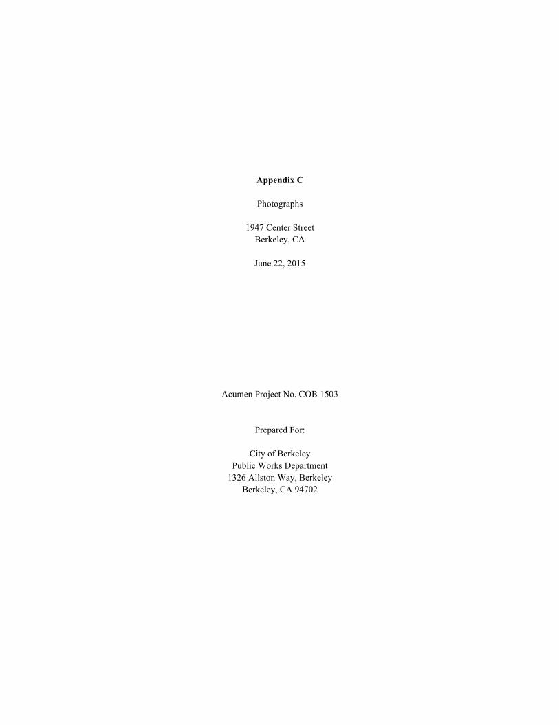
Appendix C
Photographs
1947 Center Street Berkeley, CA
June 22, 2015
Acumen Project No. COB 1503
Prepared For:
City of Berkeley Public Works Department
1326 Allston Way, Berkeley Berkeley, CA 94702
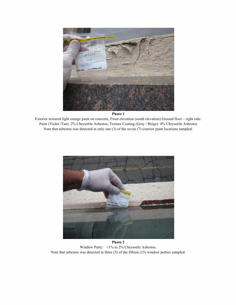
Photo 1
Exterior textured light orange paint on concrete, Front elevation (south elevation) Ground floor – right side: Paint (Violet /Tan): 2% Chrysotile Asbestos, Texture Coating (Gray / Beige): 4% Chrysotile Asbestos
Note that asbestos was detected in only one (3) of the seven (7) exterior paint locations sampled.
Photo 2
Window Putty: <1% to 2% Chrysotile Asbestos. Note that asbestos was detected in three (3) of the fifteen (15) window putties sampled.

Photo 3
Skylight Caulking: 5% to 6% Chrysotile Asbestos
Photo 4
9x9” vinyl floor tile and mastic: 3% to 15% Chrysotile Asbestos, mastic is inseparable

CITY OF BERKELEY
COMMUNITY WORKFORCE AGREEMENT
City of Berkeley Community Workforce Agreement
Page 1 of 24

Table of Contents
Preamble Purpose Recitals Article 1 Definitions Article 2 Scope of Agreement Article 3 Effect of Agreement/Subcontractors Article 4 Work Stoppages, Sympathy Strikes and Lockouts Article 5 Pre-Job Conference Article 6 No Discrimination Article 7 Union Security Article 8 Referral and Local Hiring Program Article 9 Helmets to Hardhats Article 10 Grievance Procedure Article 11 Joint Administrative Committee Article 12 Grievance Arbitration Procedure Article 13 Jurisdictional Disputes Article 14 Apprentices Article 15 Management Rights Article 16 Wage/ Benefits Article 17 Modified Master Labor Agreements Article 18 Drug and Alcohol Testing Article 19 Savings Clause Article 20 Entire Agreement Article 21 Term Signatures Agreement to be Bound
City of Berkeley Community Workforce Agreement
Page 2 of 24

COMMUNITY WORKFORCE AGREEMENT For the
City of Berkeley
This Agreement is made and entered into this July 1st, 2015 by and between the
City of Berkeley (“City”) together with other contractors and/or sub-contractors, who shall become parties to this Agreement by signing the “Agreement to be Bound” (Attachment A), and the Local Unions signatory hereto and the Alameda County Building & Construction Trades Council (“Council”) and its affiliated local unions who have executed this Agreement.
PURPOSE
The purpose of this Agreement is to support the efforts of the City to increase
employment opportunities for workers who reside in Berkeley, to help increase training and employment opportunities for Berkeley residents in the construction trades through apprenticeship and pre-apprentice programs as the students graduate from the City's schools, to promote efficiency of construction operations performed for and within the City of Berkeley and to provide for peaceful settlement of labor disputes and grievances without strikes or lockouts, thereby promoting the public interest in assuring the timely and economical completion of the projects.
RECITALS
WHEREAS, the successful completion of the City’s construction projects is of the utmost importance to the City of Berkeley; and
WHEREAS, the interests of the general public, the City, the Unions and Contractor(s) would be best served if the construction work proceeded in an orderly manner without disruption because of strikes, sympathy strikes, work stoppages, picketing, lockouts, slowdowns or other interferences with work; and
WHEREAS, the Contractor(s) and the Unions desire to mutually establish and stabilize wages, hours and calendar conditions for the workers employed on construction work for and within the City of Berkeley by the Contractor(s), and further, to encourage close cooperation among the Contractor(s) and the Union(s) to the end that a satisfactory, continuous and harmonious relationship will exist among the parties to this Agreement; and
WHEREAS, contracts for construction work within the City of Berkeley will be awarded in accordance with the applicable provisions of the Charter of the City of Berkeley, the California State Public Contract Code and the Labor Code, including but not limited to requiring competitive bidding and prevailing wages; and
WHEREAS, the City of Berkeley has the absolute right to select the lowest responsive and responsible bidder for the award of the construction contracts on the Projects; and
City of Berkeley Community Workforce Agreement
Page 3 of 24

WHEREAS, the parties signatory to this Agreement pledge their full good faith and trust to work towards a mutually satisfactory completion of the Projects;
NOW, THEREFORE, IT IS AGREED BETWEEN AND AMONG THE PARTIES HERETO, AS FOLLOWS:
ARTICLE 1
DEFINITIONS
1.1.1 “Agreement” means this Community Workforce Agreement. 1.2 "Berkeley Resident" means any individual who is a current resident of Berkeley can certify through a utility bill, or other similar means acceptable to the parties to this Agreement that the individual resides within the boundaries of the Berkeley City Limits. 1.4 “City” means the City of Berkeley. 1.5 “Completion” means that point at which the City accepts a project at issue by filing a Notice of Completion, or as otherwise provided by applicable state law. “Punch list” items and any other work within the scope of this Agreement not completed prior to commencement of revenue service shall nonetheless be included within the scope of this Agreement. It is understood by the parties that portions of the Projects may be completed in phases and Completion of any such phase may occur prior to Completion of the Projects. 1.6 “Contractor(s)” and/or “Subcontractor(s)” means any individual, firm, partnership or corporation, or combination thereof, including joint ventures, which is an independent business enterprise and has entered into a contract with the City or any of its contractors or subcontractors of any tier, with respect to the construction work necessary for any part of the Projects. This shall include subcontractors not required to be listed in the bid documents. As applicable depending on its context, “Contractor” shall refer to Contractor or Contractor and Subcontractor. 1.7 “Construction Contract(s)” means all of the contract(s) for construction of any of the Projects. 1.8 “Council” means the Alameda County Building and Construction Trades Council, AFL-CIO. 1.9 "New Apprentice” is a Berkeley Resident who is enrolled in a State of California approved apprenticeship program that is a joint labor management apprentice program for no more than twenty-four months
City of Berkeley Community Workforce Agreement
Page 4 of 24

1.11 “Projects” mean any construction project of the City whose value as estimated by the City meets or exceeds $500,000 (Five hundred thousand) dollars. 1.12 “Union” or “Unions” means the Council and any other labor organization signatory to this Agreement, acting on their own behalf and on behalf of their respective affiliates and member organizations whose names are subscribed hereto and who have through their officers executed this Agreement. 1.13 “Project Manager” means the person or persons or business entity designated by the City to oversee all phases of construction on the Projects. 1.14 “Master Labor Agreement” or “MLA” shall mean the collective bargaining agreement of each craft Union that is Signatory to this Agreement 1.15 “Calendar Day” shall mean any day, relating to any day of the week including Saturday, Sunday and public holidays. 1.16 “Apprenticeship Program” a California State-approved Joint Apprenticeship Program in the respective crafts to perform such work as is within their capabilities and which is customarily performed by the craft in which they are registered. The apprentice ratios will be in compliance with the applicable provisions of the applicable “Master Labor Agreement”.
ARTICLE 2 SCOPE OF AGREEMENT
2.1 Parties: This Agreement shall apply and is limited to all Contractors and subcontractors performing Construction Contracts necessary for the Projects, the City, the Council and any other labor organization signatory to this Agreement, acting on their own behalf and on behalf of their respective affiliates and member organizations whose names are subscribed hereto and who have, through their officers, executed this Agreement. 2.2 Project Description: This Agreement shall govern the award of all of the Construction Contracts identified by the City as part of the Projects. The City has the absolute right to combine, change, consolidate, suspend or cancel Construction Contract(s) or portions of Construction Contract(s) identified as part of the Projects. Should the City suspend or remove any contract from the Projects and thereafter authorize that construction work be commenced on such contract, then such contract shall be performed under the terms of this Agreement. Once a Construction Contract is completed it is no longer covered by this Agreement except when a Contractor is directed to engage in repairs, warranty work or modifications required by its Construction Contract with the City. For the purposes of this Agreement, a Construction Contract shall be considered Completed as set forth in Section 1.5 of this Agreement. 2.3 Covered work:
City of Berkeley Community Workforce Agreement
Page 5 of 24

2.3.1 This Agreement covers, without limitation, all on-site construction, demolition, alteration, painting or repair of buildings, structures, landscaping, temporary fencing and other works and related activities for the Projects that is within the craft jurisdiction of one of the Unions and that is part of the Projects, including, without limitation, pipelines, site preparation, survey work, demolition of existing structures and all construction, demolition or improvements required to be performed as a condition of approval by any public agency. This scope of work includes all soils and materials testing and inspection where such testing and inspection is a classification in which a prevailing wage determination has been published. 2.3.2 The Projects include work necessary for the Projects and/or in temporary yards or areas adjacent to and dedicated to the Projects, and at any on-site batch plant(s) constructed solely to supply materials to the Projects, when those sites are dedicated exclusively to the Projects. This Agreement covers all on-site fabrication work over which the City, Contractor(s) or subcontractor(s) possess the right of control (including work done for the Projects in any temporary yard or area established for the Projects.) 2.3.3 The furnishing of supplies, equipment or materials which are stockpiled for later use shall in no case be considered subcontracting. Construction trucking work, such as the delivery of ready-mix, asphalt, aggregate, sand or other fill material which are directly incorporated into the construction process as well as the off-hauling of debris and excess fill material and/or mud, shall be covered by the terms and conditions of this Agreement, to the fullest extent provided by law and by prevailing wage determinations of the California Department of Industrial Relations. Employers, including brokers, of persons providing construction trucking work shall provide certified payroll records to the City within ten (10) calendar days of written request or as required by bid specifications. 2.4 Exclusions: The following shall be excluded from the scope of this Agreement: 2.4.1 This Agreement is not intended to, and shall not affect or govern the award of public works contracts by the City which are outside the identified scope of work of the Projects. 2.4.2 This Agreement is not intended to, and shall not affect the current or anticipated operation, maintenance, access or use of any of the City's buildings or facilities, whether or not such facilities are identified in Section 1.7 above. 2.4.3 This Agreement shall not apply to a Contractor or subcontractor’s executives, managerial employees, engineering employees, design employees, supervisors (except those covered by existing building and construction trades collective bargaining agreements), office and clerical employees. 2.4.4 This Agreement shall not apply to any work performed on or near or leading to the site of work covered by this Agreement that is undertaken by state, county or other governmental bodies or their contractors; or by public or private utilities or their
City of Berkeley Community Workforce Agreement
Page 6 of 24

contractors; or by the City or its contractors for work not part of the scope of the Projects. Parties performing work shall notify in writing, The Council and The District of any work being performed near or leading to the site work that is not covered by this agreement. Further, this Agreement shall not be construed to prohibit or restrict the City or its employees from performing work on or around the Project construction sites or from entering the sites for any purposes deemed necessary or appropriate by the City. 2.4.5 This Agreement shall not apply to the off-site maintenance of leased equipment or the on-site supervision of such work. 2.4.6 This Agreement shall not apply to any start-up, calibration, performance testing, repair, maintenance, operational revisions to systems and/or subsystems performed after Completion. 2.5 Termination, Suspension and/or Delay of Work: It is understood and agreed that the City, at its sole option, may change, terminate, delay and/or suspend any and all portions of the covered work at any time. Further, the City may prohibit some or all work on certain days or during certain hours of the day to comply with applicable codes, laws or regulations, permits or to accommodate the ongoing operations of the City’s facilities and/or to mitigate the effect of the ongoing Projects’ work on the businesses and residents in the neighborhood of the Project sites; and/or require such other operational or schedule changes that may be deemed necessary, in its sole judgment, to effectively maintain the primary purpose of the City’s facilities and to remain a good neighbor to the residents and businesses in the area of any Projects. In order to permit the Contractors and Unions to make appropriate scheduling plans, the City will provide the affected Contractor and Union(s) with reasonable notice of any changes it requires pursuant to this Section. 2.6 Work covered by this Agreement within the following craft jurisdictions shall be performed under the terms of their National Agreements as follows: the NTL Articles of Agreement, the National Stack/Chimney Agreement, the National Cooling Tower Agreement, and the National Agreement of Elevator Constructors, and any instrument calibration work and loop checking shall be performed under the terms of the UA/IBEW Joint National Agreement for Instrument and Control Technicians, with the exception that Articles 4, 8,12 and 13 of this Agreement shall apply to such work.
ARTICLE 3 EFFECT OF AGREEMENT/SUBCONTRACTORS
3.1 By executing this Agreement, the Unions and the City agree to be bound by each and every provision of this Agreement. 3.2 By accepting the award of a Construction Contract for the Projects, whether as contractor or subcontractor at any tier, the Contractor/Subcontractor agrees to be bound by each and every provision of this Agreement.
City of Berkeley Community Workforce Agreement
Page 7 of 24

3.3 This Agreement shall only be binding on the signatory parties hereto and shall not apply to the parents, affiliates, subsidiaries, or other ventures of any other party. 3.4 It is understood that this Agreement, together with the referenced MLA, constitute an integrated, self-contained, stand-alone agreement, and that by virtue of having become bound to this Agreement, the Contractor will not be obligated to sign any other local, area, or national agreement as a condition of performing work within the scope of this Agreement. In addition, it is understood and agreed that all grievances and disputes involving the interpretation or application of this Agreement, including the MLA, shall be resolved according to the procedures set forth in Article 12 of this Agreement; provided, however, that should a dispute involve a single MLA and a Contractor signatory thereto, and not involve interpretation or application of this Agreement, then such dispute shall be processed and resolved pursuant to the grievance provisions of that MLA. Should there be a dispute in the first instance as to whether the provisions of Article 12 of this Agreement or the grievance procedures of a MLA apply, the dispute shall be presented initially to arbitrator Judge William Cahill or, if unavailable, arbitrator Earnest Brown, for resolution as to the applicable procedure. Such referral of a dispute as to the applicable procedures shall be done by an immediate conference call among the parties and the arbitrator, and heard and decided within three (3) calendar days. Should the arbitrator hold that Article 12 applies, the parties may, by mutual agreement, submit the issue to the same arbitrator pursuant to the provisions of Article 12, or, absent mutual agreement, commence processing the dispute at Step 1 of that Article.
3.5 Subcontractors. At the time that any Contractor enters into a subcontract with any subcontractor of any tier for the performance of construction or construction trucking work within the scope of this Agreement, the Contractor shall provide a copy of this Agreement, as it may from time to time be modified by the negotiating parties, to said subcontractor and shall require the subcontractor as a part of accepting an award of a construction subcontract to agree to be bound by each and every provision of the Agreement prior to the commencement of work.
3.5.1 Each Contractor and Subcontractor shall evidence their agreement to be bound to this Agreement by executing the Agreement To Be Bound form attached hereto as Appendix A. A copy of the Agreement To Be Bound executed by the Contractors and Subcontractors shall be submitted to the Union(s) prior to both the commencement of work and the Pre-Job Conference and will be a required submittal within the City’s bid packages. If the Contractor or Subcontractor refuses to execute the Agreement To Be Bound, then such Contractor or Subcontractor shall not be awarded a Construction Contract to perform work on the Projects. A Contractor or Subcontractor who executes the Agreement To Be Bound shall be considered a signatory party to this Agreement.
3.6 It is understood that the liability of each Contractor and Subcontractor and the liability of each Union under this Agreement shall be several and not joint. The Unions agree that this Agreement does not have the effect of creating any joint employment status between or among the City and/or any Contractor or Subcontractor.
3.7 With regard to any Contractor or subcontractor that is independently signed to any MLA, this Agreement shall in no way supersede or prevent the enforcement of any
City of Berkeley Community Workforce Agreement
Page 8 of 24

subcontracting clause contained in such MLA, except as specifically set forth in section 3.7.1 of this Agreement. Any such subcontracting clause in a MLA shall remain and be fully enforceable between each craft union and its signatory employers and no provision of this Agreement shall be interpreted and/or applied in any manner that would give this Agreement precedence over subcontracting obligations and restrictions that exist between craft Unions and their respective signatory employers under a MLA, except as specifically set forth in section 3.7.1 in this Agreement. To the extent that the provisions of this Agreement are inconsistent with any other provisions contained in a MLA, the provisions of this Agreement shall prevail
3.7.1 If a craft Union (“Aggrieved Union”) believes that an assignment of work on this Project has been made improperly by a Contractor or subcontractor, even if that assignment was as a result of another craft Union’s successful enforcement of the subcontracting clause in its MLA, as permitted by section 3.7 of this Agreement, the Aggrieved Union may submit a claim under the jurisdictional dispute resolution procedure contained in Article 13 of this Agreement and the decision rendered as part of that process shall be enforceable to require the Contractor or subcontractor that made the work assignment to assign that work prospectively to the Aggrieved Union. An award made to a craft Union under the subcontracting clause of its MLA, as permitted under section 3.7 of this Agreement, shall be valid and fully enforceable by that craft Union unless it conflicts with a jurisdictional award made pursuant to Article 12 of this Agreement. If the award made under MLA conflicts with the jurisdictional award, the award of any damages under the former shall be null and void ab initio.
ARTICLE 4 WORK STOPPAGES, STRIKES, SYMPATHY STRIKES, JURISDICTIONAL
DISPUTES AND LOCKOUTS
4.1 The Unions, City and Contractor agree that for the duration of the Projects: 4.1.1 There shall be no strikes, sympathy strikes, work stoppages, picketing, hand-billing or otherwise advising the public that a labor dispute exists, or slowdowns of any kind, for any reason, by the Unions or construction persons employed on the Projects, at a job site of the Projects or at any other facility of the City because of a dispute on the Projects. Nor shall the Unions or construction persons employed on the Projects participate in any strikes, sympathy strikes, work stoppages, picketing, hand billing, slowdowns, or otherwise advising the public that a labor dispute exists at a Project jobsite because of a dispute between Unions and Contractor(s) on any other project. 4.1.2 As to construction persons employed on the Projects, there shall be no lockout of any kind by a Contractor covered by this Agreement. It shall not be a violation of this Article if a Contractor or Subcontractor (1) suspends or terminates a portion of the Project work or (2) discharges an employee for just cause. 4.1.3 If a MLA between a Contractor and the Union expires before the Contractor completes the performance of a Construction Contract and the Union or Contractor gives notice of demand for a new or modified MLA, the Union agrees that it will not strike, picket,
City of Berkeley Community Workforce Agreement
Page 9 of 24

hand-bill, slowdown or engage in any other disruptive activity against the Contractor and the Contractor will not lockout construction persons of the Union on said Construction Contract for work covered under this Agreement. The Union and the Contractor agree that the expired MLA shall continue in full force and effect for work covered under this Agreement until a new or modified MLA is reached between the Union and Contractor. If the new or modified MLA reached between the Union and Contractor provides that any terms of the new MLA shall be retroactive, the Contractor agrees to comply with any retroactive terms of the new or modified MLA which are applicable to construction persons employed on the Projects within seven (7) calendar days. 4.2 A party to this Agreement shall institute the following procedure, prior to invoking any other action at law or equity when a breach of this Article 4 is alleged to have occurred: 4.2.1 A party invoking this procedure shall notify, by the most expeditious means available, with notice by facsimile, electronic mail or telephone to the City, to the party alleged to be in violation, to the Council and to the involved local Union if a Union is alleged to be in violation. 4.2.2 Upon receipt of said notice, the City will contact the designated permanent arbitrator, Judge William Cahill, or if unavailable, his alternate, Ernest Brown, who shall attempt to convene a hearing within twenty-four (24) hours if it is contended that the violation still exists. 4.2.3 The Arbitrator shall notify the parties by facsimile, electronic mail or telephone of the place and time for the hearing. Said hearing shall be completed in one session, which, with appropriate recesses at the arbitrator’s discretion, shall not exceed twenty-four (24) hours unless otherwise agreed upon by all parties. A failure of any party to attend said hearings shall not delay the hearing of evidence or the issuance of any award by the arbitrator. 4.2.4 The sole issue at the hearing shall be whether or not a violation of Article 4, Section 4.1 of this Agreement has occurred. The arbitrator shall have no authority to consider any matter of justification, explanation or mitigation of such violation or to award damages, which issue is reserved for court proceedings, if any. The award shall be issued in writing within three (3) hours after the close of the hearing, and may be issued without a written opinion. If any party desires a written opinion, one shall be issued within fifteen (15) calendar days, but its issuance shall not delay compliance with or enforcement of the award. The arbitrator may order cessation of the violation of this Article 4 and other appropriate relief and such award shall be served on all parties by hand or registered mail upon issuance. 4.2.5 Such award may be enforced by any Court of competent jurisdiction upon the filing of this Agreement and all other relevant documents referred to above in the following manner. Written notice of the filing of such enforcement proceedings shall be given to the other party. In the proceeding to obtain a temporary order enforcing the arbitrator’s award
City of Berkeley Community Workforce Agreement
Page 10 of 24

as issued under Section 4.2.4 of this Article 4, all parties waive the right to a hearing and agree that such proceedings may be ex parte. Such agreement does not waive any party’s right to participate in a hearing for a final order or enforcement. The Court’s order or orders enforcing the arbitrator’s award shall be served on all parties by hand or delivered by certified mail. 4.2.6 Any rights created by statute or law governing arbitration proceedings inconsistent with the above procedure or which interfere with compliance are waived by the parties. 4.2.7 The fees and expenses of the arbitrator shall be divided equally between the party instituting the arbitration proceedings provided in this Article and the party alleged to be in breach of its obligations under this article. 4.3 Liquidated Damages. If the arbitrator determines that a violation of Section 4.1 has occurred, the breaching party shall, within eight (8) hours of the issuance of the decision take all steps necessary to immediately cease such activities and return to work. If the breaching party involved does not cease such activities by the beginning of the next regularly scheduled shift following the expiration of the eight (8) hour period after the arbitrator’s issuance of the decision, then the breaching party shall pay the sum of ten thousand dollars ($10,000) as liquidated damages to the City per shift until the breach is remedied. The arbitrator shall retain jurisdiction for the sole purpose of determining compliance with this obligation and determining the amount of liquidated damages, if any; but such retention shall not prevent the moving party from seeking judicial enforcement of the initial decision.
ARTICLE 5 PRE-JOB CONFERENCE
5.1 A mandatory pre-job conference shall be held prior to the commencement of each Construction Contract. Such conference shall be attended by a representative from the participating Contractor(s), Union(s) and the Project Manager. All efforts will be made to hold the pre-job conference in sufficient time to ensure all parties have the ability to properly raise and resolve any issue that may arise out of such meeting, with a goal that such conferences will be held at least 21 work days before the work commences.
ARTICLE 6 NO DISCRIMINATION
6.1 The Contractors and Unions agree not to engage in any form of discrimination based on race, color, creed, national origin, ancestry, age, religious or political affiliation, gender, sexual orientation or disability against any person, or applicant for employment on the Projects.
ARTICLE 7 UNION SECURITY
City of Berkeley Community Workforce Agreement
Page 11 of 24

7.1 The Contractors recognize the Union(s) as the sole bargaining representative of all construction persons working within the scope of this Agreement. 7.2 All construction persons who are employed by the Contractor(s) shall, as a condition of employment, on or before the eighth (8th) day of consecutive or cumulative employment on the Projects, be responsible for the payment of the applicable monthly working dues and any associated fees uniformly required for union membership in the applicable local union which is signatory to this Agreement. Further, there is nothing in this Agreement that would prevent non-union construction persons from joining the local union.
ARTICLE 8 REFERRAL AND LOCAL HIRE PROGRAM
8.1 Referral
8.1.1 Contractor(s) performing construction work on the Projects described in the Agreement shall, in filling craft job requirements, utilize and be bound by the registration facilities and referral systems established or authorized by the Unions signatory hereto (“Job Referral System”). Such Job Referral System will be operated in a non-discriminatory manner and in full compliance with all federal, state, and local laws and regulations, including those which require equal employment opportunities and nondiscrimination. 8.1.2 The Contractor(s) shall have the right to reject any applicant referred by the Union(s), in accordance with the applicable Master Agreement. 8.1.3 The Contractor(s) shall have the unqualified right to select and hire directly all supervisors above general foreman it considers necessary and desirable, without such persons being referred by the Unions(s). 8.1.4 In the event that referral facilities maintained by the Union(s) are unable to fill the requisition of a Contractor(s) for employees within a seventy-two (72) hour period after such requisition is made by the Contractor(s), the Contractor(s) shall be free to obtain employees from any source. Contactor(s) shall promptly notify the Union(s) of any applicants hired from other sources. This provision does NOT affect core employees as defined below. 8.1.5 Unions shall exert their utmost efforts to recruit sufficient numbers of skilled craft persons to fulfill the requirements of the Contractor(s). 8.1.6 Core Employees: All parties agree to make a good faith effort to refer on a priority basis, consistent with the non-discriminatory referral procedures of the hall, qualified and available, and bona-fide Berkeley Residents for Project work.
City of Berkeley Community Workforce Agreement
Page 12 of 24

8.1.7 The parties also recognize and support the City’s commitment to provide opportunities for participation on the Projects to Berkeley Residents who are regular, experienced employees (“Core” employees) of contractors and subcontractors awarded work on the Projects and who do not traditionally work under a local collective bargaining agreement(s). In furtherance of this commitment, the parties agree that such contractors and subcontractors awarded work on the Projects may request by name, and the local will honor, referral of persons who have applied to the local union for Project work and who demonstrate the following qualifications: (1) Possess any license required by state or federal law for the Project work to be performed; (2) Have worked a total of at least one thousand (1,000) hours in the construction craft during the prior three (3) years; (3) Were on the Contractor’s active payroll for at least sixty (60) out of the one hundred and eighty (180) calendar days prior to the contract award; (4) Have the ability to perform safely the basic functions of the applicable trade, and (5) Are Berkeley residents. The Union will refer to such Contractor one journeyman employee from the hiring hall out-of-work list for the affected trade or craft, and will then refer one of such Contractor’s “core” employees as a journeyman and shall repeat the process, one and one, until such Contractor’s crew requirements are met or until such Contractor has hired five (5) “core” employees, whichever occurs first. Thereafter, all additional employees in the affected trade or craft shall be hired exclusively from the hiring hall out-of-work list(s). For the duration of the Contractor’s work the ratio shall be maintained and when the Contractor’s workforce is reduced, employees shall be reduced in the same ratio of core employees to hiring hall referrals as was applied in the initial hiring. 8.1.8 The Contractor shall notify the appropriate Union of the name and social security number of each direct hire and each direct hire shall register with the Union’s hiring hall before commencing Project work. If there is any question regarding an employee’s eligibility under this Subsection 8.2.1, the City Representative, at a Union’s request, shall obtain satisfactory proof of such from the Contractor. 8.2 Local Hire
8.2.1 To the extent allowed by law and consistent with the non-discriminatory referral procedures of the Union hiring halls, the Parties agree to a goal that Berkeley Residents will perform a minimum of 20% of the hours worked, on a craft by craft basis for the Projects. The Contractor(s) shall make good faith efforts to reach this goal through the utilization of the Unions' hiring hall procedures. The Unions shall exercise their best efforts in their recruiting and training of Berkeley Resident workers and in their hiring hall procedures to facilitate this 20% goal on the Projects. In the event that referral facilities
City of Berkeley Community Workforce Agreement
Page 13 of 24

maintained by the Union(s) are unable to fulfill the 20% local hire requirement, paragraph 8.2.2 of this Article shall not apply. Contractors shall document all efforts to hire locally and provide such documents to the City of Berkeley. The Council will provide an annual census of Berkeley residents, in each of the crafts party to this agreement, to the City of Berkeley. This report will be provided by August 1 of each year of this agreement. . 8.2.2 Should any of the contractors performing work on the Projects fail to meet this 20% goal and fail to demonstrate efforts to do so, through a specific submittal process to be included in their contractual requirements and enforced by the grievance procedure, the contract's 10% retention will be held until such time that this failure is remedied, but not longer than sixty (60) calendar days after the date of substantial completion of the Projects or as required by law, in addition to the breach of contract remedies available to the parties for non-performance under this Agreement.
8.2.3 Apprenticeship & Workforce Development
A) Consistent with the requirements of California Labor Code §§ 1776, 1777.5 and 1777.6, Contractor(s) will be required to hire 1 New Apprentice Berkeley resident for every $500,000 dollars as determined by the engineer’s estimate. The New Apprentice(s) must work a minimum of 10% of the total craft’s work hours. The contractor may deploy the apprentice to work on another concurrent project in order to meet the minimum hours, and those hours will be counted towards the total hours of the craft on the Berkeley project. Certified Payroll must reflect the hours worked.
Contractor must fully document efforts to hire a New Apprentice, through the following steps: 1) requesting New Apprentices through the Union dispatch procedure, 2) contacting a minimum of three MC3-approved pre-apprenticeship training programs for referral of Berkeley residents. Unions shall provide written documentation to the contractor in response to dispatch requests to fulfill the New Apprentice requirement.
B) There can be no more than one (1) entry-level New Apprentice for each craft, provided said crafts have apprenticeship openings and the general contractor will be able to include New Apprentices hired by their subcontractor to meet this requirement. Unions will agree to cooperate with Contractor(s) in furnishing apprentices as requested and the hiring of the apprentices will be in accordance to the Apprenticeship provisions listed in the Master Agreements and or the union agreements with the division of apprenticeship standards, and the apprentices shall be properly supervised and paid in accordance with provisions contained within the MLA’s. The Unions and Contractors will agree to cooperate with local pre-apprenticeship programs to ensure Berkeley residents have the opportunity to apply for and enter the into the apprenticeship programs.
C) The intent of this provision is to utilize Berkeley Resident New Apprentices to the fullest extent permissible by state law and the MLA. Failure of Contractor(s) and their subcontractors to maintain qualified apprentices on the job will be subject to further penalties as determined by the Grievance Committee as identified in Article 12. 8.11 Enforcement, Compliance & Reporting.
City of Berkeley Community Workforce Agreement
Page 14 of 24

Contractors will be required to submit Certified Weekly Payrolls to the City along with monthly workforce utilization reports documenting the Contractor’s compliance with the requirements described in this article. At a minimum the monthly reports must include 1) data on Berkeley Resident’s work hour utilization on a craft by craft basis, 2) number of New Apprentices hired and the hours they have worked, 3) documentation showing any requests made to the union dispatchers for Berkeley Residents and the Union’s response to the request. Enforcement of this article shall be according to the Grievance and Arbitration procedure outlined in Article 12.
ARTICLE 9 HELMETS TO HARDHATS
9.1 The parties recognize a desire to facilitate the entry into the Building and Construction Trade Union(s) of Veterans who are interested in careers in the building and construction industry. The parties agree to utilize the services of the Center for Military Recruitment, Assessment and Veteran’s Employment (“Center”) and the Center’s “Helmets to Hardhats” program to serve as a resource for preliminary orientation, assessment of construction aptitude, referral to apprenticeship programs or hiring halls, counseling and mentoring, support network, employment opportunities and other needs as identified by the parties. 9.2 The Union(s) and Contractor(s) agree to coordinate with the Center to participate in an integrated database of Veterans interested in working on this Project and of apprenticeship and employment opportunities for this Project. To the extent permitted by law, the Union(s) will give credit to such Veterans for bona fide, provable past experience.
ARTICLE 10 GRIEVANCE PROCEDURE
10.1 Any Contractor which is not otherwise bound through an agreement with a Union to a grievance procedure which confers jurisdiction to consider and resolve disputes over the imposition of discipline or dismissal of its construction persons working on this Project shall be bound to the arbitration procedure contained in the MLA of the craft representing the employee(s) involved in the dispute. For the purposes of this Article, such grievance procedure shall be limited to disputes regarding the imposition of discipline or dismissal arising from work covered by the Agreement. Such Contractor shall not impose discipline or dismissal on its construction persons covered by this Agreement without just cause.
ARTICLE 11 JOINT ADMINISTRATIVE COMMITTEE
11.1 The parties to this Agreement shall establish a Joint Administrative Committee comprised of at least one (1) and up to two (2) representatives representing the City; two (2) representatives of the signatory Unions and The Council, and one (1) industry representative, mutually selected by the City and The Council. Each representative shall
City of Berkeley Community Workforce Agreement
Page 15 of 24

designate an alternate who shall serve in his or her absence for any purpose contemplated by this Agreement. 11.2 The Joint Administrative Committee shall meet at the request of either party, but not less than once each quarter, to review the implementation of the Agreement and the progress of the Projects including, but not limited to, compliance with Article 8, prevailing wage, safety, Workforce development and Industry trends. Requests for certified payroll made by a Joint Labor/Management Committee to which the Union(s) signatory to this Agreement are a party shall be provided as allowed by law.
ARTICLE 12 GRIEVANCE ARBITRATION PROCEDURE
12.1 The parties understand and agree that in the event any dispute arises out of the meaning, interpretation or application of the provisions of this Agreement, the same shall be settled by means of the procedures set out herein. No grievance shall be recognized unless the grieving party provides notice in writing to the signatory party with whom it has a dispute within seven (7) calendar days after becoming aware of the dispute, but in no event more than thirty (30) calendar days after it reasonably should have become aware of the event giving to the dispute. The time limits in this Article 12 may be extended by mutual written agreement of the parties. 12.2 Grievances shall be settled according to the following procedures:
Step 1: Within seven (7) calendar days after the receipt of the written notice of grievance, the Business Representative of the involved Local Union, the City’s authorized representative, representative of the construction person, and the representative of the involved Contractor shall confer and attempt to resolve the grievance.
Step 2: In the event that the representatives are unable to resolve the dispute
within seven (7) calendar days after its referral to Step 1, either involved party may submit it within three (3) calendar days to Grievance Committee. The Grievance Committee shall consist of one (1) person selected by the City and one (1) person selected by the Council, which shall meet within seven (7) calendar days after such referral (or such longer time as mutually agreed upon by all representatives of the subcommittee), to confer in an attempt to resolve the grievance. The decision of the Grievance Committee shall be legal, final and binding. If the dispute is not resolved within seven (7) calendar days after its referral or such longer time as mutually agreed upon) it may be referred within seven (7) calendar days by either party to Step 3.
Step 3: Within seven (7) calendar days after referral of a dispute to Step 3, the
representatives shall submit the matter to the designated permanent Arbitrator, Judge William Cahill.
12.3 In the event that Judge Cahill is unavailable, the arbitrator shall be Earnest Brown.
City of Berkeley Community Workforce Agreement
Page 16 of 24

12.4 The Arbitrator shall arrange for a hearing no later than fourteen (14) calendar days after the matter has been submitted to arbitration. A decision shall be given to the parties within five (5) calendar days after completion of the hearing unless such time is extended by mutual agreement. A written opinion from the Arbitrator may be requested by any party. The time limits specified in any step of the Grievance Procedure set forth in Section 12.1 may be extended by mutual agreement of the parties initiated by the written request of one party to the other, at the appropriate step of the Grievance Procedure. However, failure to process a grievance, or failure to respond in writing within the time limits provided above, without the request for an extension of time, shall be deemed a waiver of such grievance without prejudice, or without precedent to the processing of and/or resolution of like or similar grievances or disputes. 12.5 The decision of the Arbitrator shall be binding by all parties. The Arbitrator shall not have authority to change, amend, add, or detract from any of the provisions of the Agreement. The expense of the Arbitrator shall be borne equally by both parties. 12.6 In order to encourage the resolution of disputes and grievances at Step 1 and 2 of this Grievance Procedure, the parties agree that such settlements shall not be precedent-setting.
ARTICLE 13 JURISDICTIONAL DISPUTES
13.1 The assignment of Covered Work will be solely the responsibility of the Contractor/Employer(s) performing the work involved, and such work assignments will be in accordance with the Plan for the Settlement of Jurisdictional Disputes in the Construction Industry (the “Plan”) or any successor Plan. 13.2 All jurisdictional disputes on this Project between or among the Union(s) and the Contractor/Employer(s), parties to this Agreement, shall be settled and adjusted according to the present Plan established by the Building and Construction Trades Department, or any other plan or method of procedure that may be adopted in the future by the Building and Construction Trades Department. Decisions rendered shall be final, binding and conclusive on the Contractor/Employer(s) and Union(s) parties to this Agreement.
13.2.1 If a dispute arising under this Article involves the Northern California Carpenters Regional Council or any of its subordinate bodies, an Arbitrator shall be chosen by the procedures specified in Article V, Section 5, of the Plan from a list composed of John Kagel, Thomas Angelo, Robert Hirsch and Thomas Pagan and the Arbitrator’s hearing on the dispute shall be held at the offices of the California State Building and Construction Trades Council in Sacramento, California, within fourteen (14) calendar days of the selection of the Arbitrator. All other procedures shall be as specified in the Plan. 13.3 All jurisdictional disputes shall be resolved without the occurrence of any strike, work stoppage, or slow-down of any nature, and the Contractor/Employer(s)’ assignment
City of Berkeley Community Workforce Agreement
Page 17 of 24

shall be adhered to until the dispute is resolved. Individuals violating this Section shall be subject to immediate discharge. 13.4 Each Contractor/Employer(s) shall conduct a Pre-Job Conference with the Council prior to commencing Covered Work. The Primary Employer, Coordinator and the District will be advised in advance of all such conferences and may participate if they wish. Pre-job conferences for different Contractor(s) may be held together.
ARTICLE 14 APPRENTICES
14.1 Recognizing the need to maintain continuing support of programs designed to develop adequate numbers of competent workers in the construction industry, the Contractor (s) shall employ apprentices in the respective crafts to perform such work as is within their capabilities and which is customarily performed by the craft in which they are indentured. 14.2 The apprentice ratios will be in compliance with the applicable provisions of the California Labor Code and Prevailing Wage Rate Determination. 14.3 There shall be no restrictions on the utilization of apprentices in performing the work of their craft provided they are properly supervised. 14.4 All Apprentices will come from a State approved Labor Management Apprenticeship program.
ARTICLE 15 MANAGEMENT RIGHTS
15.1 The Contractor shall retain full and exclusive authority for the management of their operations, including the right to direct their work force in their sole discretion with regard to the following: the hiring, promotion, transfer, layoff, corrective action or discharge for just cause of its employees (in accordance with Article 9); the determination of the number of employees needed for the Project work; the selection/hiring of foremen and supervisors; the assignment and schedule of work; the requirement of overtime work, the determination of when it will be worked, and the number of employees engaged in such work, except as otherwise limited by the terms of this Agreement and/or the MLA. No rules, customs or practices shall be permitted or observed which limit or restrict production, or limit or restrict the working efforts of construction persons except that the lawful manning provisions of the MLA shall be recognized.
ARTICLE 16 WAGES/BENEFITS
16.1 Wages. All construction persons covered by this Agreement shall be classified in accordance with work performed and paid the hourly wage rates for those classifications
City of Berkeley Community Workforce Agreement
Page 18 of 24

in the applicable MLA for such craft work and in compliance with the applicable prevailing wage rate determination.
16.2 Benefits. Contractor agrees to pay contributions into established construction person benefit funds in the amounts designated in the appropriate MLA; provided, however, that each Contractor and Union agree that only such bona fide construction person benefits as included in the prevailing wage determination shall be included in this requirement and required to be paid by the Contractor under this Agreement; provided further, however, that this provision does not relieve Contractors signatory to a local collective bargaining agreement with a signatory Union which would be applicable to the Projects from making any other fund contributions (including, but not limited to, those for contract administration), required by such local agreement. Contractor shall not be required to pay contributions to any other trust funds to satisfy their obligation under this Article. By signing this Agreement, the Contractors adopt and agree to be bound by the written terms of the legally established Trust Agreements, specifying the detailed basis on which the payments are to be made into, and the benefits paid out of, such Trust Funds.
16.3 Compliance. It shall be the responsibility of the Contractor(s) and Unions to investigate and monitor compliance with the provisions of the agreement contained in Article 15. Nothing in this agreement shall be construed to interfere with or supersede the usual and customary legal remedies available to the Unions and/or employee benefit Trust Funds to collect delinquent Trust Fund contributions from Contractors on the Project.
ARTICLE 17 MODIFIED MASTER LABOR AGREEMENTS
17.1 Certain Provisions Shall Not Apply. Provisions negotiated into the new or modified MLA which are less favorable to the Contractor than those uniformly required of employers for construction work normally covered by those agreements or which may be construed to apply exclusively or predominately to work covered by this Agreement shall not apply to work covered by this Agreement. Any disagreement between the parties regarding the application of the provisions of any new or modified collective bargaining agreement to work covered by this Agreement shall be resolved under the dispute and grievance arbitration procedures set forth in Article 12 hereof.
ARTICLE 18 DRUG and ALCOHOL TESTING
18.1 The use, sale, transfer, purchase and/or possession of a controlled substance, alcohol and/or firearms at any time during the work day is prohibited. 18.2 Employer shall be allowed to utilize employment drug screens. All personnel are subject to random alcohol and drug/alcohol testing at any time, except, the following changes will apply. Employer shall follow said Unions Master Labor Agreement drug polices, regulations and limits. Body fluid tests will utilize urine and saliva specimens. An
City of Berkeley Community Workforce Agreement
Page 19 of 24

Employer may also selectively require an employee to undergo alcohol or drug/alcohol testing if the Employer has reasonable cause to believe that an employee’s ability to work safely may be impaired. All requirements and activities of the Employer with regard to drug/alcohol testing shall comply with the provisions of State law.
ARTICLE 19 SAVINGS CLAUSE
19.1 The parties agree that in the event any article, provision, clause, sentence or word of this Agreement is determined to be illegal or void as being in contravention of any applicable law, by a court of competent jurisdiction the remainder of the Agreement shall remain in full force and effect. The parties further agree that if any article, provision, clause, sentence or word of the Agreement is determined to be illegal or void, by the court of competent jurisdiction, the parties shall substitute, by mutual agreement, in its place and stead, an article, provision, clause, sentence or word which will meet the objections to its validity and which will be in accordance with the intent and purpose of the article, provision, clause, sentence or word in question. 19.2 The parties also agree that in the event that a decision of a court of competent jurisdiction materially alters the terms of this Agreement such that the intent of the parties is defeated, then the entire Agreement shall be null and void.
ARTICLE 20 ENTIRE AGREEMENT
20.1 This Agreement represents the complete understanding of the parties. The provisions of this Agreement, including the MLA, shall apply to the work covered by this Agreement. Where a subject covered by the provisions of this Agreement is also covered by a MLA, the provisions of this Agreement shall prevail. Where a subject is covered by the provisions of a MLA and is not covered by this Agreement, the provisions of the MLA shall prevail. Nothing contained in a MLA, working rule, by-laws, constitution or other similar document of the Unions shall in any way affect, modify or add to this Agreement unless otherwise specifically set forth in this Agreement or mutually agreed to in writing executed by the parties. 20.2 The parties agree that this Agreement covers all matters affecting wages, hours, and other terms and conditions of employment and that during the term of this Agreement the parties will not be required to negotiate on any further matters affecting these or any other subject not specifically set forth in this Agreement except by mutual agreement of the parties. 20.3 This Agreement may be executed in counterparts, such that original signatures may appear on separate pages and when bound together all necessary signatures shall constitute an original. Facsimile signature pages transmitted to other parties to this Agreement shall be deemed the equivalent to original signatures.
City of Berkeley Community Workforce Agreement
Page 20 of 24
ARTICLE 21 TERM
21.1 The Agreement shall be included as a condition of the award of the Construction Contracts. 21.2 The Agreement shall continue in full force and effect for a term of three years from the Effective Date and shall be applicable to all Projects until completion that are advertised for bidding during the term. 21.3 This Agreement shall continue in full force and effect until Completion of the Project. The parties may mutually agree to extend and/or amend this Agreement.
City of Berkeley Community Workforce Agreement
Page 21 of 24

SIGNATURES City of Berkeley By:________________________________________ Title: Date:___________________ Alameda County Building & Construction Trades Council, AFL-CIO By:_______________________________________ Date:___________________ Signatory Unions
Asbestos Workers, Local 16 Boilermakers, Local 549
By: _________________________ By: _________________________
Bricklayers & Allied Craftsmen, Local 3 Cement Masons, Local 300
By: _________________________ By: _________________________
Electrical Workers, Local 595 Elevator Constructors, Local 8
By: _________________________ By: _________________________
Hod Carriers, Local 166 Iron Workers, Local 378
By: _________________________ By: _________________________
Laborers, Local 67 Laborers, Local 304
By: _________________________ By: _________________________
Operating Engineers, Local 3 Plasterers, Local 66
By: _________________________ By: _________________________
Roofers, Local 81 Sheet Metal Workers, Local 104
By: _________________________ By: _________________________
Sign Display, Local 510 Sprinkler Fitters, Local 483
By: _________________________ By: _________________________
City of Berkeley Community Workforce Agreement
Page 22 of 24
Teamsters, Local 853 United Association of Journeymen and Apprentices Fitting Industry, Underground Utility & Landscape, Local 355
By: _________________________ By: _________________________
United Association of Steamfitters, Ironworkers City and the RDA Council of Pipefitters, Plumbers, & Gas California Fitters, Local 342 By: _________________________ By:__________________________
Council No. 16 Northern California International Union of Laborers Painters & Allied Trades (On behalf of Painters, Local 3; Carpet & Linoleum Layers, Local 12; Glass Workers, Local 169; Auto& Marine Painters, Local 1176) By: _________________________ By: _________________________
Northern California Carpenters Regional Council (on behalf of Carpenters, Local 713; Carpenters, Local 2236; Lathers, Local 68L; Millwrights, Local 102; Pile Drivers, Local 34) By: _________________________
City of Berkeley Community Workforce Agreement
Page 23 of 24

AGREEMENT TO BE BOUND
The undersigned, as a Contractor or Subcontractor ("Contractor") on a City Project (“Project”), for and in consideration of the award to it of a contract to perform work on said Project, and in further consideration of the mutual promises made in the Project’s Community Workforce Agreement ("Agreement"), a copy of which was received and is acknowledged, hereby: 1. Accepts and agrees to be bound by the terms and conditions of the Agreement, together with any and all amendments and supplements now existing or which are later made to said Agreement.
2. Certifies that it has no commitments or agreements which would preclude its full and complete compliance with the terms and conditions of said Agreement;
3. Agrees to secure from any Contractor (as defined in said Agreement) which is or becomes a subcontractor (of any tier) to it, and from any successors, a duly executed Agreement to be bound in form identical to this document.
4. Contractor agrees that it shall be bound by all applicable trust agreements and plans for the provision of such fringe benefits as accrue to the direct benefit of the construction persons, including Health and Welfare, Pension, Training, Vacation, and/or other direct benefits provided pursuant to the appropriate craft agreement contained in Schedule "A" of Agreement.
Date: _______________
Company Name: ____________________________________________
Name of Prime Contractor or Higher Level Subcontractor: __________________________________________________________
Name of Project: _______________________
Signature: ______________________________________
Print Name: ______________________________________
Title: ______________________________________
Contractor’s License #: _______________________
Motor Carrier Permit (CA) #: _______________________
City of Berkeley Community Workforce Agreement
Page 24 of 24

CITY OF BERKELEY BIDDING & CONTRACTING UNDER THE COMMUNITY WORKFORCE AGREEMENT (CWA)
• Local Workforce Hiring Goals
The City of Berkeley’s local workforce-hiring goal is 20% of craft hours worked, on a craft by craft basis on locally funded projects. City Staff will provide a template to be used by the general contractor (GC) for reporting the summary of the total work hours and total number of Berkeley residents, this report is to be submitted with each certified payroll (CP), including CP for each subcontractor. GC can compile the report for the subcontractors or can require each sub to prepare their own report. Please include documentation detailing efforts to meet the local hire goals, i.e., dispatch requests to the unions. Please note the GC is responsible for the local hire component for the entire project. This report will be reviewed by the Joint Administrative Committee (JAC) to monitor compliance of the local workforce hiring goals. The JAC may periodically request contractors to attend a JAC meeting to describe and discuss their local hire efforts. GC and the subs are strongly encouraged to utilize the city-funded pre-apprenticeship program, Rising Sun Energy Center, for the hiring of Berkeley residents on the projects. Rising Sun staff will work closely with the trades and the contractor to facilitate the hiring of the program graduates for entry into the trades. City staff will conduct periodic interviews of workers throughout the project.
• Certified Payrolls Contractors are required to submit certified payrolls (CP) on a monthly basis to the Public Works Project Manager. The monthly report described above shall reflect the information provided on the Certified Payrolls. Address & trade for each worker must be included in Certified Payroll and is subject to verification by City staff. Please redact Social Security Numbers from CP prior to sending to city staff. When submitting CP, please attach any documentation pertinent to your good faith efforts, such as dispatch requests & union hall responses to those requests.
• Core (Regular, experienced) Employees A non-signatory contractor may use up to five (5) of its own “core” employees provided that the first worker hire comes from the union, second worker is “core”, third worker from the union, fourth worker is “core”, and so forth. The contractors’ worker must comply with the Union Hall’s registration process; the contractor and subcontractor may request by name, and the local will honor, referral of the core employee(s) who have applied to the local union hall for work on the project and who demonstrate the following qualifications: 1) possess any license required by state or federal law, 2) have worked at least 1,000 hours in the construction craft during the prior three years, 3) have been on the Contractor’s active payroll for at least sixty (60) out of the one hundred and eighty (180) hours in the calendar year immediately prior to contract award, 4) must have the ability to safely perform the basic functions of the applicable trade, and 5) must reside in Berkeley.
• Hiring Plan A hiring plan is to be submitted prior to the Notice to Proceed date, with the understanding that the workforce may change during the project. The hiring plan is used as baseline information, with the monthly workforce utilization reports, certified payroll and dispatch request documentation serving as confirmation of good faith efforts to hire locally.
• Apprentices Consistent with the requirements of California Labor Code § 1776, 1777.5 and 1777.6, contractors and their subcontractors are required to hire at least one Berkeley resident as a First Period Apprentice for every $500,000 or more of total bid amount, thereafter, for every five million dollars of the total bid amount the Prime Contractor and their subcontractors are required to hire one additional first period apprentice. Berkeley residents that participate in local workforce development programs will be screened and referred for the apprenticeship opportunities, city staff, union halls & training programs will facilitate this process.
• California Prevailing Wages CWA Summary rev. 8/15

CITY OF BERKELEY BIDDING & CONTRACTING UNDER THE COMMUNITY WORKFORCE AGREEMENT (CWA)
All construction workers will be paid prevailing wages as determined by the State of California. Benefits are the established labor-management vacation, pension or other form of deferred compensation plan, apprenticeship and health benefit funds for each hour worked. Any local collectively bargained wage and/or fringe benefit increase shall be recognized on the date on which they become effective.
• Agreement to be Bound All general contractors and all sub-contractors, including trucking, and regardless of tier, must sign an Agreement to be Bound to the CWA. This agreement binds the contractor to the terms of the CWA for the awarded project only. It does not bind any contractor to a union agreement for any other project.
• Pre-Job Conference Prior to start of construction, the successful general contractor and all subcontractors are required to attend a pre-job conference with the affected Building & Construction Trades Council. Agreements to be Bound shall be submitted prior to the Pre-job Conference. General Contractor and subcontractors will make craft/trade work assignments at this meeting. Should any union disagree, it may follow the established jurisdictional dispute resolution process provided in the Community Workforce Agreement. The pre-job conference may be held via conference call arranged by the building trades, city staff will also participate in the pre-job conference.
• Joint Administrative Committee This Committee shall be comprised of up to two (2) representative selected by the City; up to two (2) representatives of the signatory Unions and Alameda County Building and Construction Trades Council; and one (1) contractor representative, mutually selected by the City and the Alameda County Building and Construction Trades Council. Each representative shall designate an alternate who shall serve in his or her absence for any purpose contemplated by this Agreement. The Joint Administrative Committee shall meets regularly to review the implementation of the Agreement and the progress of the Projects including, but not limited to, compliance with Article 8, prevailing wage, safety, craft workforce levels and construction progress. The JAC may contact the Contractor and/or their subcontractors in writing to request their presence at a JAC meeting to describe good faith efforts throughout the project or at the end of a project. CWA Administration Delfina Geiken Employment Programs Administrator Department of Health, Housing and Community Services
2180 Milvia, 2nd floor Berkeley, CA 94704 [email protected] (510) 981-7551
Nathan Dahl Community Development Project Coordinator Department of Health, Housing and Community Services
2180 Milvia, 2nd floor Berkeley, CA 94704 [email protected] (510) 981-5405
To view the full City Council report: http://www.cityofberkeley.info/Clerk/City_Council/2015/06_Jun/Documents/2015-06-23_Item_52_Contract_Community_Workforce_-_Rev.aspx
CWA Summary rev. 8/15
