(19) tzz¥z¥ t - patentimages.storage.googleapis.com · gr hr hu ie is it li lt lu lv mc mk ......
TRANSCRIPT

Printed by Jouve, 75001 PARIS (FR)
(19)E
P3
075
436
A1
TEPZZ¥Z754¥6A_T(11) EP 3 075 436 A1
(12) EUROPEAN PATENT APPLICATION
(43) Date of publication: 05.10.2016 Bulletin 2016/40
(21) Application number: 15162515.9
(22) Date of filing: 02.04.2015
(51) Int Cl.:B01D 53/90 (2006.01) C07C 69/40 (2006.01)
B01D 53/94 (2006.01)
(84) Designated Contracting States: AL AT BE BG CH CY CZ DE DK EE ES FI FR GB GR HR HU IE IS IT LI LT LU LV MC MK MT NL NO PL PT RO RS SE SI SK SM TRDesignated Extension States: BA MEDesignated Validation States: MA
(71) Applicant: Afton Chemical LimitedBracknell,Berkshire RG12 2UW (GB)
(72) Inventors: • Anderson, Steven John
Church Lawton, Cheshire ST7 3BG (GB)• Pilbeam, Jonathan James
Woking, Surrey GU21 4RE (GB)
(74) Representative: Simpson, Tobias Rutger et alMathys & Squire LLP The Shard 32 London Bridge StreetLondon SE1 9SG (GB)
(54) DIESEL EXHAUST FLUID SOLUTIONS AND METHODS OF USING THE SAME
(57) Formulations of diesel exhaust fluid ("DEF") thatinclude one or more functional additives and the use ofsuch formulations for reducing deposits in the exhaust
systems of engines that use DEF requiring Selective Cat-alytic Reduction ("SCR") catalysts are described.

EP 3 075 436 A1
2
5
10
15
20
25
30
35
40
45
50
55
Description
FIELD OF THE INVENTION
[0001] The present invention relates generally to formulations of diesel exhaust fluid ("DEF") that include one or morefunctional additives and the use of such formulations for reducing deposits in the exhaust systems of engines that useDEF requiring Selective Catalytic Reduction ("SCR") catalysts.
BACKGROUND OF THE INVENTION
[0002] Diesel engines are the preferred means of producing torque for use in a wide range of applications rangingfrom uses in transportation such as heavy-duty trucks and trains, off-road agricultural and mining equipment to the largescale production of on-site electrical power to name a few. Their virtually unmatched power to mass ratios and therelative safety of their fuel makes them almost the only choice for use in applications such as long-haul trucks, tractors,earth movers, combines, surface mining equipment, non-electric locomotives, high capacity emergency power generatorsand the like.[0003] Diesel engines operate at high internal temperature. One consequence of their high operating temperatures isthat at least some of the nitrogen present in the engine at the moment of combustion may combine with oxygen to formNOx including species such as NO and NO2. Another consequence of their high operating temperatures is that dieselexhaust at or near the point of exit from the engine is very hot.[0004] A compound such as NOx is problematic because it readily combines with volatile organic compounds in theatmosphere to form smog. NOx is regarded as a pollutant and virtually every industrialized nation regulates the levelsof NOx that can be legally discharged into the atmosphere. The regulations governing NOx emissions are expected tobecome even stricter. Fortunately, engine and equipment manufacturers have developed systems for reducing the levelsof NOx produced by the combustion of diesel fuel and released into the environment. Still, with even tighter limits on theamounts of these compounds that can be released into the atmosphere there remains a need for improved materialsand methods for reducing the levels of NOx while not compromising the efficiency or productivity of the engine.[0005] One approach to reducing NOx emissions is to treat diesel exhaust with a formulation of urea and water forthe catalytic reduction of the oxides of nitrogen in the exhaust. One specific formulation, referred to as diesel exhaustfluid (DEF), is especially useful in combination with Selective Catalytic Reduction (SCR) systems. One of the drawbacksof using DEF, however, is that the DEF produces white crystalline deposits inside of the exhaust system, most notablyon any raised or sharp edge such as the mixer, a propeller or turbine shaped component made from material similar tothe exhaust, that promotes turbulence in the exhaust pipe upstream of the catalyst brick that is used for reduction ofNOx. The turbulence aids in atomization, evaporation and hydrolysis of the DEF into gaseous ammonia. These whitecrystalline deposits also form downstream of the mixer on the internal surfaces of the exhaust system as well as on theDEF injector tip and the catalyst brick itself. The conventional means for removing the deposits is either mechanicallyscraping them off of the metal surfaces or replacing the components once deposits form on them. Therefore, reducingor preventing the formation of these deposits is advantageous and cost effective.
SUMMARY OF THE INVENTION
[0006] In one aspect, the present invention provides an exhaust after-treatment composition comprising a compoundcapable of providing ammonia above about 150 °C, an adduct of an α-substituted succinic anhydride with a polyalkyleneglycol, a polyalkylene glycol derivative, or a mixture thereof, and water, wherein the α-substituted succinic anhydride isa compound of formula (I)
wherein R1 is C8-C22alkyl, C8-C22alkenyl, or C6-C10arylalkyl[0007] In another aspect, the present invention provides a process for generating ammonia in an exhaust streamcomprising vaporizing an exhaust after-treatment composition at about 150 °C or more to produce ammonia, whereinthe exhaust after-treatment composition comprises a compound capable of providing ammonia above about 150 °C, an

EP 3 075 436 A1
3
5
10
15
20
25
30
35
40
45
50
55
adduct of an α-substituted succinic anhydride with a polyalkylene glycol, a polyalkylene glycol derivative, or a mixturethereof, and water, wherein the α-substituted succinic anhydride is a compound of formula (I)
wherein R1 is C8-C22alkyl, C8-C22alkenyl, or C6-C10arylalkyl.[0008] In a third aspect, the invention provides a process for reducing or preventing formation of deposits in an exhauststream comprising vaporizing an exhaust after-treatment composition at about 150 °C or more to produce ammonia,wherein the exhaust after-treatment composition comprises a compound capable of providing ammonia above about150 °C, an adduct of an α-substituted succinic anhydride with a polyalkylene glycol, a polyalkylene glycol derivative, ora mixture thereof, and water, wherein the α-substituted succinic anhydride is a compound of formula (I)
wherein R1 is C8-C22alkyl, C8-C22alkenyl, and C6-C10arylalkyl.[0009] In another aspect, the invention relates to the use of an adduct as defined herein for inhibiting the formation ofdeposits in an exhaust stream.
BRIEF DESCRIPTION OF THE DRAWINGS
[0010]
Figure 1 is a schematic diagram of a representative SCR exhaust treatment system for a diesel engine.
Figure 2 is a graphical representation of deposit formation (in grams) in an exhaust treatment system over time (inhours) in the presence of DEF or a solution in accordance with one embodiment of the present invention.
Figure 3 is a schematic of a testing rig for simulating a diesel exhaust treatment system.
DETAILED DESCRIPTION OF THE INVENTION
[0011] The present invention relates to aqueous solution-based compositions comprising a constituent capable ofreleasing gaseous ammonia above about 150 °C and an α-substituted succinic anhydride adduct. The compositionsare useful for limiting the formation of deposits in any spray device intended for the after-treatment of exhaust gases,more particularly Selective Catalytic Reducer (SCR) devices. The aqueous solution contains a compound capable ofdecomposing to gaseous ammonia which vaporizes easily on injection and which significantly limits the deposits formedon the "cold" walls. Moreover, the use of this solution can be implemented in any spray device intended for the after-treatment of exhaust gases.[0012] According to a first aspect of the invention, an exhaust after-treatment composition comprises: a) a compoundcapable of providing ammonia above about 150 °C; b) an adduct of an α-substituted succinic anhydride with a polyalkyleneglycol, a polyalkylene glycol derivative, or a mixture thereof; and c) water.[0013] In certain embodiments, the α-substituted succinic anhydride is a compound of formula (I)

EP 3 075 436 A1
4
5
10
15
20
25
30
35
40
45
50
55
wherein R1 is C8-C22alkyl, C8-C22alkenyl, or C6-C10arylalkyl.[0014] In certain embodiments, the adduct of an α-substituted succinic anhydride, as described herein, is with apolyalkylene glycol. In other embodiments, the adduct is with a polyalkylene glycol derivative. In still other embodiments,the adduct is with a mixture of a polyalkylene glycol and a polyalkylene glycol derivative. Embodiments where the adductis with a mixture of a polyalkylene glycol and a polyalkylene glycol derivative include mixtures of one or more polyalkyleneglycol, as described herein, with one or more polyalkylene glycol derivative, as described herein. The use of mixturesof polyalkylene glycols and/or polyalkylene glycol derivatives produces mixtures of adducts with the α-substituted succinicanhydride.[0015] In certain embodiments, the polyalkylene glycol may be a polyethylene glycol, a polypropylene glycol, a poly-butylene glycol, a co-polymer between two or more of a polyethylene glycol, a polypropylene glycol, and a polybutyleneglycol, or mixtures thereof. For example, in certain embodiments, the polyalkylene glycol may be a co-polymer betweena polyethylene glycol and a polypropylene glycol such as a poloxamer (e.g., Pluronic), i.e., a polyoxypropylene flankedby two polyoxyethylene groups. In other embodiments, the polyalkylene glycol may be a co-polymer between a poly-ethylene glycol and a polybutylene glycol or between a polypropylene glycol and a polybutylene glycol. In still otherembodiments, the polyalkylene glycol may be a mixture of different polyalkylene glycols, such as, for example, a mixtureof a polyethylene glycol with a polypropylene glycol or a mixture of a polyethylene glycol with a co-polymer as describedabove. In further embodiments, the polyalkylene glycol may be a mixture of different polyethylene, polypropylene, orpolybutylene glycols, e.g., a mixture of PEG 200 and PEG 400. In other embodiments, the polyalkylene glycol is a singlepolyalkylene glycol.[0016] In certain embodiments, the polyalkylene glycol derivative may be a polyethylene glycol derivative, a polypro-pylene glycol derivative, a polybutylene glycol derivative, a derivative of a co-polymer between two or more of a poly-ethylene glycol, a polypropylene glycol, and a polybutylene glycol, and mixtures thereof. For example, in certain em-bodiments, the polyalkylene glycol derivative may be a derivative of a co-polymer between a polyethylene glycol and apolypropylene glycol. In still other embodiments, the polyalkylene glycol derivative may be a mixture of different poly-alkylene glycol derivatives, such as, for example, a mixture of a polyethylene glycol derivative with a polypropyleneglycol derivative or a mixture of a polyethylene glycol derivative with a derivative of a co-polymer as described above.In further embodiments, the polyalkylene glycol derivative may be a mixture of derivatives of different polyethylene,polypropylene, or polybutylene glycols, e.g., a mixture of a PEG 200 derivative and a PEG 400 derivative. In someembodiments, the polyalkylene glycol derivative is a single polyalkylene glycol derivative. A polyalkylene glycol derivativemeans a polyalkylene glycol having one of the two alcohol moieties of the glycol capped with a substituent group. Thesubstituent group of the polyalkylene glycol derivative includes C1-C6alkyl (e.g., methyl, butyl), allyl, benzyl, substitutedbenzyl, cycloalkyl, such as cyclohexyl, and fatty acid alkoxylate esters, such as oleic acid ethoxylate. In a preferredembodiment, the polyalkylene glycol derivative is a methoxy derivative, i.e., one of the two alcohol moieties of the glycolis capped with a methyl group.[0017] In further embodiments, a polyethylene glycol may have an average molecular weight from 200 (PEG 200) upto 4000 (PEG 4000). For example the polyethylene glycol includes, but is not limited to, PEG 200, PEG 300, PEG 400,PEG 600, PEG 1000, and PEG 4000. In certain preferred embodiments, the polyethylene glycol is PEG 1000.[0018] In certain embodiments, the molecular weights for polypropylene glycols, polybutylene glycols, and co-polymersare from about 100 to about 10,000. In other embodiments, the molecular weights are from about 200 to about 4,000.In further embodiments, the molecular weights are from about 200 to about 1500.[0019] In certain embodiments, the adduct may be a compound of formula (II)

EP 3 075 436 A1
5
5
10
15
20
25
30
35
40
45
50
55
wherein R1 is C8-C22alkyl, C8-C22alkenyl, or C6-C10arylalkyl; and R2 is a polyoxyalkylene alcohol or a polyoxyalkylenealcohol derivative.[0020] In yet other embodiments, the adduct may be a compound of formula (III)
wherein R1, at each occurrence, is independently C8-C22alkyl, C8-C22alkenyl, or C6-C10arylalkyl; and L1 is a polyoxy-alkylenyl.[0021] The skilled artisan readily recognizes that the reactions for forming adducts of formula (II) and formula (III) arerandom reactions. Therefore, the compounds of formula (II) and formula (III) can be a mixture of positional isomers. Forexample, a compound of formula (II) can comprise the following two adducts:
whereas the compound of formula (III) can comprise the following three adducts:
[0022] As used herein, the reference to a compound of formula (II) means one or more of a compound of formula (IIa),(IIb), or a mixture thereof, whereas a reference to a compound of formula (III) means one or more of a compound offormula (IIIa), (IIIb), (IIIc), or a mixture thereof.[0023] In still more embodiments, the adduct may be a compound of formula (IV)
wherein R1 is C8-C22alkyl, C8-C22alkenyl, or C6-C10arylalkyl; and R2 and R3 are each independently a polyoxyalkylenealcohol or a polyoxyalkylene alcohol derivative.[0024] As used herein, the term "C8-C22alkyl" means a straight or branched chain saturated hydrocarbon having from8 to 22 carbon atoms (e.g., octyl, decyl, 4,6,8-trimethylnonan-2-yl, hexadecyl, octadecyl, dodecyl). In certain embodi-ments, alkyl groups of the C8-C22alkyl are straight chain saturated hydrocarbons. In other embodiments, alkyl groupsof the C8-C22alkyl are branched chain saturated hydrocarbons.

EP 3 075 436 A1
6
5
10
15
20
25
30
35
40
45
50
55
[0025] As used herein, the term "C8-C22alkenyl" means a straight or branched chain unsaturated hydrocarbon con-taining at least one carbon-carbon double bond and having from 8 to 22 carbon atoms (e.g., dec-2-en-1-yl, 4,6,8-trimethylnon-2-en-2-yl, hexadec-2-en-1-yl, octadec-2-en-1-yl) and includes hydrocarbons like tetrapropenyl. A carbon-carbon double bond of the C8-C22alkenyl may have either E or Z geometry. In certain embodiments, R1 is (E)-octadec-2-en-1-yl, (E)-hexadec-2-en-1-yl, or (E)-(4,6,8-trimethylnon-2-en-2-yl). In certain embodiments R1 is
where n is 12-14. In some embodiments, alkenyl groups of the C8-C22alkenyl are straight chain unsaturated hydrocarbons.[0026] In other embodiments, alkenyl groups of the C8-C22alkenyl are branched chain unsaturated hydrocarbons.[0027] As used herein, the term "C6-C10arylalkyl" means an aryl group appended to the parent molecular moietythrough an alkylene chain of 1 to 18 carbons, wherein the alkylene chain may be either straight or branched. An "alkylene,"as used herein, means a divalent group derived from a straight or branched chain hydrocarbon. Representative examplesof alkylene include, but are not limited to, -CH2-, -CH2CH2-, -CH2CH2CH2-, -CH2CH(CH3)CH2-, and-CH2CH(CH3)CH(CH3)CH2-. The C6-C10aryl is a phenyl or a bicyclic ring system containing an aromatic ring whereinall of the ring members of the bicyclic ring system are carbons. The bicyclic carbocyclic aryl is naphthyl, dihydronaph-thalenyl, tetrahydronaphthalenyl, indanyl, or indenyl. The phenyl and bicyclic carbocyclic aryls are attached to the parentmolecular moiety through any carbon atom contained within the phenyl or bicyclic carbocyclic aryl.[0028] As used herein, the phrase "polyoxyalkylene alcohol", for example at R2 and R3, means the polyether portionof a polyalkylene glycol, as defined herein, that is attached to the parent molecular moiety at the first carbon atom of thepolyether chain and terminating in an alcohol moiety. The polyoxyalkylene alcohol may be derived from a co-polymerof more than one polyalkylene glycol. Representative polyoxyalkylene alcohols have a formula including, but not limitedto, -C2H4(OC2H4)xOH, -C3H6(OC3H6)yOH, and -C2H4(OC2H4)a(OC3H6)b(OC2H4)aOH, wherein a, b, x, and y indicaterepeating units. In one embodiment, x is an integer from 3 to 230, preferably from 3 to 100, and more preferably from3-35. In other embodiments, y is an integer from 3 to 175; independently a is an integer from 1 to 50; and independentlyb is an integer from 1 to 50. In certain embodiments, the polyoxyalkylene alcohol at R2 or R3 is-CH2CH2(OCH2CH2)20-22OH.[0029] As used herein, the phrase "polyoxyalkylene alcohol derivative", for example at R2 and R3, means a polyoxy-alkylene alcohol, as defined herein, where the terminal alcohol is capped with a substituent group. The substituent groupof the polyoxyalkylene alcohol derivative includes C1-C6alkyl (e.g., methyl, butyl), allyl, benzyl, substituted benzyl, cy-cloalkyl, such as cyclohexyl, and fatty acid alkoxylate esters, such as oleic acid ethoxylate. In certain embodiments, R2
and R3 is a derivative of CH2CH2(OCH2CH2)20-22OH. In preferred embodiments, the polyoxyalkylene alcohol derivativeis a methoxy derivative, e.g., CH2CH2(OCH2CH2)20-22OCH3.[0030] As used herein, the term "polyoxyalkylenyl", for example at L1, means the polyether portion of a polyalkyleneglycol, as defined herein, that links two molecular moieties at a carbon atom at either end of the polyether chain. Thepolyoxyalkylenyl may be derived from a co-polymer of more than one polyalkylene glycol. Representative polyoxyalkyle-nyls have a formula including, but not limited to, -C2H4(OC2H4)x-, -C3H6(OC3H6)y-, and-C2H4(OC2H4)a(OC3H6)b(OC2H4)a- , wherein a, b, x, and y indicate repeating units.[0031] Compounds of formulas (I), (II), (III), and (IV) may have either the "R" or "S" stereochemistry depending on thearrangement of substituents around the chiral carbon atom. The terms "R" and "S" used herein are configurations asdefined in IUPAC 1974 Recommendations for Section E, Fundamental Stereochemistry, Pure Appl. Chem., 1976, 45:13-30.[0032] The α-substituted succinic anhydride adducts of the invention include any combination of independently selectedR1, R2, R3, L1, polyalkylene glycol, polyalkylene glycol derivative, polyoxyalkylene alcohol, polyoxyalkylene alcoholderivative, and polyoxyalkylenyl, as these terms are defined herein.[0033] In preferred embodiments, the composition comprises an adduct of an α-substituted succinic anhydride offormula (I) with a polyethylene glycol and R1 is a C16-C18alkenyl. In one embodiment, the adduct is with a PEG 200 toa PEG 4000. In another embodiment, the adduct is with a PEG 1000.[0034] In other embodiments, the adduct comprises a compound of formula (II), where R1 is a C16-C18alkenyl and R2
is a polyoxyethylene alcohol. In one embodiment, R1 is
and n is 12-14. In another embodiment R2 is - CH2CH2(OCH2CH2)20-22OH, or a derivative thereof. In a further embod-

EP 3 075 436 A1
7
5
10
15
20
25
30
35
40
45
50
55
iment, R1 is
n is 12-14; and R2 is -CH2CH2(OCH2CH2)20-22OH, or a derivative thereof. In a further embodiment, the derivative is amethoxy derivative.[0035] In still other embodiments, the adduct comprises a compound of formula (III), where R1 is a C16-C18alkenyland L1 is a polyoxyethylenyl (i.e., -C2H4(OC2H4)x-). In one embodiment, R1 is
and n is 12-14. In another embodiment L1 is -CH2CH2(OCH2CH2)20-22- In a further embodiment, R1 is
n is 12-14; and L1 is -CH2CH2(OCH2CH2)20-22-.[0036] In still further embodiments, the adduct comprises a mixture of two or more of formulas (II), (III), and (IV),wherein R1, R2, R3, L1 are as defined herein.[0037] According to certain embodiments of the invention, the exhaust after-treatment composition is an aqueoussolution comprising 15 to 40% v/v of at least one constituent which decomposes to gaseous ammonia. In a particularembodiment, the constituent is 32.5% v/v of the solution. In another embodiment, the aqueous solution comprises morethan about 10 ppm, preferably more than about 100 ppm, of the α-substituted succinic anhydride adduct (e.g., formula(II), (III), and/or (IV)). In order to obtain satisfactory efficiency, for example a reduction of more than at least 50% in thedeposits, the solution can comprise about 100 to about 5000 ppm, and advantageously about 175 to about 1000 ppm,or about 200 to about 500 ppm of the α-substituted succinic anhydride adduct. In one embodiment of the presentinvention, the constituent is selected from urea and its derivatives.[0038] The present invention provides an exhaust after-treatment composition comprising a compound capable ofproviding gaseous ammonia above about 150 °C. In some embodiments, the compound is a compound capable ofproviding gaseous ammonia above about 175 °C. In another embodiment, the compound is a compound capable ofproviding gaseous ammonia above about 200 °C.[0039] The aqueous solution can contain one or more additives in addition to the α-substituted succinic anhydrideadduct (e.g., formula (II), (III), and/or (IV)) such as, for example, anti-foaming agents (alcohols, alkenes combined withone or more non-ionic surfactants, etc.), co-solvents intended to promote the dissolution of the adduct in the aqueoussolution. The aqueous solution is prepared in the usual manner by mixing its constituents, preferably at ambient tem-perature, typically within a temperature range generally from 10 to 60 °C.[0040] In one embodiment, the water in the aqueous composition is demineralized water. As used herein the term"demineralized water" refers to water that includes very low levels of minerals in general, and in particular very low levelsof sulphur, alkaline metals, earth metals, vanadium, arsenic, ash, or any other compounds that are known to damageSCR catalysts. Demineralized water for use in the inventive formulations can be made by any method known in the artfor reducing the level of contaminants in demineralized water including distillation and reverse osmosis.[0041] In certain embodiments, the aqueous solutions comply with standard ISO 2241-1. One embodiment of theinvention is the use of the aqueous solution in any spray device intended for the after-treatment of exhaust gases and,more particularly, SCR devices. Another embodiment includes adding the adduct as a readily soluble concentrate to atank that already includes standard DEF. In some embodiments, these methods include the step of supplying pre-packaged quantities of a concentrate of the adduct which can be added to a reductant tank that includes urea. In someembodiments, these methods include the step of determining the composition of the reductant to insure that the relativelevels of water, urea and the adduct in the reductant system are suitable for use in SCR.[0042] One aspect of the present invention provides a process for generating ammonia in an exhaust stream comprisingvaporizing an exhaust after-treatment composition at about 150 °C or more to produce ammonia, wherein the exhaustafter treatment composition comprises a compound capable of providing ammonia above about 150 °C, an adduct ofan α-substituted succinic anhydride with a polyalkylene glycol, a polyethylene glycol derivative, or a mixture thereof, asdefined hereinabove, and water. In certain embodiments, α-substituted succinic anhydride is a compound of formula

EP 3 075 436 A1
8
5
10
15
20
25
30
35
40
45
50
55
(I), as defined above. In certain embodiments, the process employs an adduct comprising a compound of formula (II),(III), and/or (IV) as these formulas and their substituents are defined hereinabove.[0043] In particular embodiments, the exhaust stream is treated with a SCR based exhaust treatment system. In atypical SCR based exhaust treatment system, a SCR catalyst is positioned in the exhaust stream of a diesel engine.The catalyst is positioned such that the temperature of the exhaust fumes contacting the surface of the catalyst is highenough to sustain the reaction of the NOx in the exhaust fumes with the reductant but not so high that the heat producedby the engine and the chemical reactions that take place in the exhaust stream damages the catalyst.[0044] Referring now to FIG. 1, a schematic diagram of a typical heavy duty diesel exhaust treatment system (2). AnSCR catalyst (4) is positioned within an exhaust pipe (6). The exhaust pipe has two ends. One end (8) is connected toa source of NOx (10) and the other end (12) is vented to the atmosphere (14). A typical system may also include anoption additional pair of catalysts, (16) and (18), these are positioned before (16) and after (18) the SCR catalyst (4).The oxidation catalysts catalyse the oxidation of various compounds in the exhaust stream including organic moleculesand un-reacted ammonia.[0045] Because the SCR system requires a reductant such as ammonia or urea, the SCR system can include a systemfor storing, and delivering the reductant to the catalyst. Still referring to FIG. 1, for example, reductant storage vessel(20) is connected to a first delivery tube (22). First delivery tube (22) has two ends; the first end the inlet (24) of tube(22) is connected to storage vessel (20) while the second end the outlet (26) of tube (22) is connected to a reductantdelivery valve (28) that regulates the flow of the reductant from tube (22) to a second delivery tube (30). Tube (30) alsohas two ends the first end inlet (32) is connected to the outlet of valve (28) while the second end outlet (34) of seconddelivery tube (32) is connected to the exhaust pipe (6). The outlet (34) of second delivery tube (30) is connected toexhaust pipe (6) such that the reductant in second delivery tube (30) is delivered onto or near the surface of SCR catalyst(4) by outlet (34).[0046] In some embodiments, the SCR system (2) may include a device for maintaining the temperature of the reductantin storage vessel (20). In some configurations, the first reductant delivery tube (22), the reductant delivery value (28)and/or the second reductant delivery tube (30) may also be equipped with a device (40) to help regulate the temperatureof the reductant in the system. In some embodiments of the invention, the device for regulating the temperature of thereductant (40) may be selected from the group consisting of: insulation, a heating coil or sock; and/or a cooling or warmingjacket or some combination thereof.[0047] In some embodiments, the system (2) may further include an optional mixing device (43) supplied to eitherperiodically or continuously agitate the contents of reductant storage vessel (20). Vessel (20) may also be equippedwith a temperature sensor (44) to measure the temperature of the contents of vessel (20). Vessel (20) may also beequipped with a probe (46) for measuring the nitrogen content of the material stored in vessel (20). In some embodiments,the system may be supplied with a controller (42) which may include inputs from sensors connected to the exhaustand/or SCR systems. The controller may also be equipped with a Central Processing Unit or dedicated logic circuitsthat regulate the dispersion of reductant to the system as necessary to maintain the release of NOx within acceptablelimits. The controller may also be used to monitor the temperature or the reductant delivery system and perhaps tocontrol portions of the system dedicated to maintain the reductant within an acceptable temperature range. In someembodiments, the same controller is used to regulate the rate and/or frequency of the agitator associated with reductantstorage tank one. In some embodiments, the controller may be used to monitor the level of reductant and/or the com-position of the reductant in reductant storage vessel (20). Some exhaust systems include an oxidation catalyst (18),generally located downstream of the SCR catalyst. Some oxidative catalysts can oxidize ammonia and formaldehyde,thereby preventing the release of these compounds into the atmosphere.[0048] Sensors that can be used to monitor the level of compounds that include ammonia and urea in DEF formulationinclude, but are not limited, to those disclosed in US Patent Number 7,722,813 issued on May 25, 2010, which isincorporated herein by reference in its entirety. Some of these sensors operate by measuring the ability of a formulationof DEF to transfer heat and correlating this property with the concentration of urea in the system. In some versions thesensor in the form of a probe is inserted into the DEF formulation. In some embodiments, the system includes a circuitused to supply a current applied to a heating element positioned in a portion of the probe that is submerged in the DEFin order to produce heat and a temperature sensing device that is also submerged in the DEF. The amount of currentthat must be applied to the heating element in order to produce a discernable effect on the temperature sensor isinfluenced by the composition of the liquid surrounding the probe tip. The relationship between the levels of current thatmust be applied to affect a temperature change measured at the probe’s temperature sensor can be determined as afunction of urea content in the DEF. Once the relationship between current and urea content is known for a given probeand a formulation with certain components the relationship can then be used to infer the level of urea in a sample ofDEF by measuring the amount of current required to effect a change in temperature. Any method that can be used todetermine or at least estimate the composition of DEF in a storage tank or anywhere in a SCR system can be used topractice the invention.[0049] Spec grade DEF is widely available for use in SCR based NOx reduction systems. Spec grade DEF includes

EP 3 075 436 A1
9
5
10
15
20
25
30
35
40
45
50
55
on the order of about 32.5 wt. % urea and purified water. These formulations are optimized to prolong catalyst life andinclude extremely low levels of impurities that can cause deposits or poison expensive SCR catalysts. Accordingly, SCRspec grade DEF and the formulations disclosed herein have virtually undetectable levels of sulphur, metals, non-com-bustible fillers, other inert contaminants, compounds whose effects on SCR catalyst life are unknown.[0050] This technology is well known and has widespread use in Europe, and its use has been growing in NorthAmerica. Still some challenges persist in the use of this technology including the tendency for urea deposits to form inthe exhaust system especially between the DEF dosing inlet and upstream of selective catalytic reduction (SCR) catalystand the relatively high freezing point of 32.5 wt. % urea in water solutions. This latter problem has been addressed bycertain formulation nitrogen-based reductants which have lower freezing points than aqueous urea and still function.Some of these formulations are disclosed in US Patent Application No. 13/193,793 filed on July 29, 2010, the disclosureof which is incorporated herein by reference in its entirety.[0051] The problem of urea deposition in the DEF feeding system can cause reduced fuel efficiency, particulate filterfailure, damage to the SCR catalyst bed, and even engine failure as a significant build-up of urea in the exhaust systemmay cause excessive back pressure. Some exhaust systems are equipped with pressure sensors, in part to detect theeffects of urea deposition. These sensors are part of a monitoring system that enables the diesel operator to detectproblematic urea build-up and to take appropriate action such as shutting down the system until the deposits can bephysically removed from the system. Still other systematic approaches to addressing the problem of urea build-up is toalter the position of the DEF feed tube and/or time the release of DEF into a portion of the exhaust system immediatelyup-stream of the SCR catalytic bed in order to minimize the time that urea rich DEF is in contact with the DEF feedsystem and pre-SCR section of the exhaust system.[0052] According to a third aspect of the invention is a process for reducing or preventing formation of deposits in anexhaust stream comprising vaporizing an exhaust after-treatment composition at about 150 °C or more to produceammonia, wherein the exhaust after treatment composition comprises a compound capable of providing ammonia aboveabout 150 °C, an adduct of an α-substituted succinic anhydride with a polyalkylene glycol, a polyethylene glycol derivative,or a mixture thereof, as defined hereinabove, and water. In certain embodiments, α-substituted succinic anhydride is acompound of formula (I), as defined above. In certain embodiments, the process employs an adduct comprising acompound of formula (II), (III), and/or (IV) as these formulas and their substituents are defined hereinabove.[0053] The deposits formed in an exhaust stream can, in certain embodiments, be any deposits that result from thedecomposition of urea and include deposits containing one or more of biuret, cyanuric acid, ammelide, ammeline andmelamine. In one embodiment, the deposits in the exhaust stream comprise cyanuric acid-based deposits.[0054] Although certain embodiments of the present invention may be described individually herein, it is understoodby the skilled artisan that any one embodiment can be combined with any other embodiment or embodiments, and iscontemplated by the scope of the instant invention.
Synthetic Methods
[0055] The adducts of an α-substituted succinic anhydride with a polyalkylene glycol can be prepared by methodsknown to those skilled in the art. For example, approximately a 1:1, 2:1, or 1:2 molar equivalent of alkyl substitutedsuccinic anhydride to polyalkylene glycol can be used to prepare compounds of formula (II), (III) and (IV), respectively.The polyalkylene glycol can be heated in a stirred vessel to approximately 60 to 100°C and then charged with pre-heated(to melt) substituted succinic anhydride for 2-24 hours, and more typically 4-8 hours. The reaction can be monitored byFT-IR and chromatography techniques such as GC, GPC and HPLC.
Examples
[0056] Example 1. Preparation of additive compound. An adduct of an α-substituted succinic anhydride with a poly-alkylene glycol was prepared as follows: A 1:1 +/-0.2 molar equivalent of a C16-C18 alkenyl α-substituted succinicanhydride to polyethylene glycol was used to prepare certain compounds of formula (II). The polyethylene glycol washeated in a stirred vessel to approximately 60 to 100°C and then charged with pre-heated (to melt) C16-C18 α-substitutedsuccinic anhydride for approximately 4-8 hours. The reaction was monitored by FT-IR and GPC.[0057] Example 2. Aqueous test solutions are prepared by heating the additive compound prepared in Example 1 to50°C for at least one hour until the preparation is visually homogeneous. The heated preparation is added to commerciallyobtained diesel exhaust fluid (DEF) (ISO 22241 32.5% high-purity urea and 67.5% deionized water) to produce a 10%additive/90% DEF solution w/w and the resulting 10% additive solution is shaken on a mechanical shaker for approxi-mately one hour. The 10% additive solution is then added to commercially obtained diesel exhaust fluid (DEF) (ISO22241 32.5% high-purity urea and 67.5% deionized water) at the desired treat rate to prepare an aqueous test solutionof the desired additive concentration in parts per million volume (ppmv). The aqueous test solutions with the additive ofExample 1, at 250 ppmv, are tested as compared to DEF without the additive to determine if the additive compounds
EP 3 075 436 A1
10
5
10
15
20
25
30
35
40
45
50
55
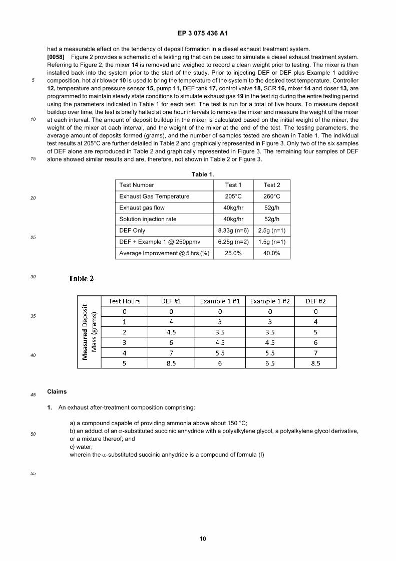
had a measurable effect on the tendency of deposit formation in a diesel exhaust treatment system.[0058] Figure 2 provides a schematic of a testing rig that can be used to simulate a diesel exhaust treatment system.Referring to Figure 2, the mixer 14 is removed and weighed to record a clean weight prior to testing. The mixer is theninstalled back into the system prior to the start of the study. Prior to injecting DEF or DEF plus Example 1 additivecomposition, hot air blower 10 is used to bring the temperature of the system to the desired test temperature. Controller12, temperature and pressure sensor 15, pump 11, DEF tank 17, control valve 18, SCR 16, mixer 14 and doser 13, areprogrammed to maintain steady state conditions to simulate exhaust gas 19 in the test rig during the entire testing periodusing the parameters indicated in Table 1 for each test. The test is run for a total of five hours. To measure depositbuildup over time, the test is briefly halted at one hour intervals to remove the mixer and measure the weight of the mixerat each interval. The amount of deposit buildup in the mixer is calculated based on the initial weight of the mixer, theweight of the mixer at each interval, and the weight of the mixer at the end of the test. The testing parameters, theaverage amount of deposits formed (grams), and the number of samples tested are shown in Table 1. The individualtest results at 205°C are further detailed in Table 2 and graphically represented in Figure 3. Only two of the six samplesof DEF alone are reproduced in Table 2 and graphically represented in Figure 3. The remaining four samples of DEFalone showed similar results and are, therefore, not shown in Table 2 or Figure 3.
Claims
1. An exhaust after-treatment composition comprising:
a) a compound capable of providing ammonia above about 150 °C;b) an adduct of an α-substituted succinic anhydride with a polyalkylene glycol, a polyalkylene glycol derivative,or a mixture thereof; andc) water;wherein the α-substituted succinic anhydride is a compound of formula (I)
Table 1.
Test Number Test 1 Test 2
Exhaust Gas Temperature 205°C 260°C
Exhaust gas flow 40kg/hr 52g/h
Solution injection rate 40kg/hr 52g/h
DEF Only 8.33g (n=6) 2.5g (n=1)
DEF + Example 1 @ 250ppmv 6.25g (n=2) 1.5g (n=1)
Average Improvement @ 5 hrs (%) 25.0% 40.0%

EP 3 075 436 A1
11
5
10
15
20
25
30
35
40
45
50
55
wherein R1 is C8-C22alkyl, C8-C22alkenyl, or C6-C10arylalkyl.
2. The composition of claim 1, wherein the polyalkylene glycol is selected from a polyethylene glycol, a polypropyleneglycol, a polybutylene glycol, a co-polymer between two or more of a polyethylene glycol, a polypropylene glycol,and a polybutylene glycol, and mixtures thereof; and the polyalkylene glycol derivative is selected from a polyethyleneglycol derivative, a polypropylene glycol derivative, a polybutylene glycol derivative, a derivative of a co-polymerbetween two or more of a polyethylene glycol, a polypropylene glycol, and a polybutylene glycol, and mixtures thereof.
3. The composition of claim 2, wherein the polyalkylene glycol is a polyethylene glycol, preferably a polyethylene glycol200 (PEG 200) to a polyethylene glycol 4000 (PEG 4000), more preferably a polyethylene glycol 1000 (PEG 1000).
4. The composition of any of claims 1-3, wherein R1 is C16-C18alkenyl.
5. The composition of any of claims 1-4, wherein the compound capable of providing ammonia is urea.
6. The composition of any of claims 1-5, wherein the composition comprises about 15 % to about 40 % by weight ofthe compound capable of providing ammonia.
7. The composition of any of claims 1-6, wherein the composition comprises about 100 ppm to about 5000 ppm of theadduct.
8. The composition of any of claims 1-7, wherein the adduct comprises a compound of formula (II)
whereinR1 is C8-C22alkyl, C8-C22alkenyl, or C6-C10arylalkyl, and is preferably
wherein n is 12-14; andR2 is a polyoxyalkylene alcohol or a polyoxyalkylene alcohol derivative, and is preferably-CH2CH2(OCH2CH2)20-22OH, or a derivative thereof.
9. The composition of any of claims 1-7, wherein the adduct comprises a compound of formula (III)

EP 3 075 436 A1
12
5
10
15
20
25
30
35
40
45
50
55
whereinR1, at each occurrence, is independently C8-C22alkyl, C8-C22alkenyl, or C6-C10arylalkyl, and is preferably
wherein n is 12-14; andL1 is a polyoxyalkylenyl.
10. The composition of any of claims 1-7, wherein the adduct comprises a compound of formula (IV)
whereinR1 is C8-C22alkyl, C8-C22alkenyl, or C6-C10arylalkyl, and is preferably
wherein n is 12-14; andR2 and R3 are each independently a polyoxyalkylene alcohol or a polyoxyalkylene alcohol derivative, and is preferably-CH2CH2(OCH2CH2)20-22OH, or a derivative thereof.
11. The composition of any of claims 1-7, wherein the adduct comprises a mixture of two or more of formulas (II), (III),and (IV)
whereinR1, at each occurrence, is independently C8-C22alkyl, C8-C22alkenyl, or C6-C10arylalkyl, and is preferably
wherein n is 12-14;R2 and R3, at each occurrence, are each independently a polyoxyalkylene alcohol or a polyoxyalkylene alcoholderivative, and is preferably -CH2CH2(OCH2CH2)20-22OH, or a derivative thereof; andL1 is a polyoxyalkylenyl.
12. The composition of any of claims 1-11, wherein the polyalkylene glycol derivative is a methoxy derivative.
13. A process for generating ammonia in an exhaust stream comprising:

EP 3 075 436 A1
13
5
10
15
20
25
30
35
40
45
50
55
vaporizing an exhaust after-treatment composition according to any of claims 1-12 at about 150 °C or more toproduce ammonia.
14. A process for reducing or preventing formation of deposits in an exhaust stream comprising:
vaporizing an exhaust after-treatment composition according to any of claims 1-12 at about 150 °C or more toproduce ammonia.
15. Use of an adduct as defined in any of claims 1-4 or 8-12, for inhibiting the formation of deposits in an exhaust stream.
16. Use according to claim 15, wherein the adduct is used as part of a composition according to any of claims 1-12.
17. The process of claim 14, or the use of claim 15 or claim 16, wherein the deposits comprise cyanuric acid-baseddeposits.

EP 3 075 436 A1
14

EP 3 075 436 A1
15

EP 3 075 436 A1
16

EP 3 075 436 A1
17
5
10
15
20
25
30
35
40
45
50
55

EP 3 075 436 A1
18
5
10
15
20
25
30
35
40
45
50
55

EP 3 075 436 A1
19
5
10
15
20
25
30
35
40
45
50
55

EP 3 075 436 A1
20
5
10
15
20
25
30
35
40
45
50
55

EP 3 075 436 A1
21
REFERENCES CITED IN THE DESCRIPTION
This list of references cited by the applicant is for the reader’s convenience only. It does not form part of the Europeanpatent document. Even though great care has been taken in compiling the references, errors or omissions cannot beexcluded and the EPO disclaims all liability in this regard.
Patent documents cited in the description
• US 7722813 B [0048] • US 13193793 B [0050]
Non-patent literature cited in the description
• IUPAC 1974 Recommendations for Section E, Fun-damental Stereochemistry. Pure Appl. Chem., 1976,vol. 45, 13-30 [0031]