15 criticare 506dn - service manual
TRANSCRIPT

8/22/2019 15 Criticare 506DN - Service Manual
http://slidepdf.com/reader/full/15-criticare-506dn-service-manual 1/125
eQuality™ 506DN
Vital Signs Monitor
Service Manual

8/22/2019 15 Criticare 506DN - Service Manual
http://slidepdf.com/reader/full/15-criticare-506dn-service-manual 2/125
Copyright
COPYRIGHT © CRITICARE SYSTEMS, INC., 2009
CRITICARE SYSTEMS, INC. (Criticare) owns all rights to this unpublished workand intends to maintain this work as confidential. Criticare may also seek to
maintain this work as an unpublished copyright. This publication is to be used solely forthe purposes of reference, operation, maintenance, or repair of Criticare equipment.
No part of this publication may be reproduced in any manner or disseminated forother purposes.
In the event of inadvertent or deliberate publication, Criticare intends to enforce itsrights to this work under copyright laws as a published work. Those having access
to this work may not copy, use, or disclose the information in this work unlessexpressly authorized by Criticare to do so.
All product specifications, as well as information contained in this publication, are
subject to change without notice.
All information contained in this publication is believed to be correct. CriticareSystems, Inc., shall not be liable for errors contained herein nor for incidental orconsequential damages in connection with the furnishing, performance, or use of
this material.
This publication may refer to information and products protected by copyrightsor patents and does not convey any license under the patent rights of CriticareSystems, Inc., nor the rights of others. Criticare Systems, Inc., does not
assume any liability arising out of any infringements of patents or other rights
of third parties.
PROPERTY OF CRITICARE SYSTEMS, INC.
ALL RIGHTS RESERVED
eQuality™ Vital Signs Monitor, DOX™ Digital Oximetry, ComfortCuff™ NIBP and
Multi-Site™ SpO2 Sensors are trademarks of Criticare Systems, Inc.

8/22/2019 15 Criticare 506DN - Service Manual
http://slidepdf.com/reader/full/15-criticare-506dn-service-manual 3/125
Contents
Copyright................................................................................................................ii
Contents................................................................................................................ iii
Warranty.. ............... ................ .............. ............... ............... ................ .............. .... vii
Service Return Policy.......................................................................................... viii
EC Declaration of Conformity................................................................................ix
Section 1 – Introducti on
Description.................................................................................................................... 1-1Intended Use................................................................................................................. 1-1
Non-Invasive Blood Pressure (NIBP)............................................................................ 1-2
ComfortCuff® Technology ................................................................................. 1-2
Description of NIBP Measurement..................................................................... 1-2
NIBP Clinical Testing and Accuracy................................................................... 1-3
Cuff Inflation and Pressure Protection ............................................................... 1-3
Heart Rate..................................................................................................................... 1-4
DOX™ Pulse Oximetry Measurement (SpO2) .............................................................. 1-5
Definition ............................................................................................................ 1-5
DOX™ Digital Oximetry ..................................................................................... 1-5
Method............................................................................................................... 1-5SpO2 Clinical Testing and Accuracy .................................................................. 1-6
Specifications................................................................................................................ 1-7
Symbols ...................................................................................................................... 1-10
Safety.......................................................................................................................... 1-12
Software Error Related Hazard Mediation ....................................................... 1-14
Potential Interference....................................................................................... 1-14
Leakage Current .............................................................................................. 1-14
Voltage Fluctuations......................................................................................... 1-15
Equipotential Ground .......................................................................................1-15
Defibrillation, HF, and Electronic Device Protection......................................... 1-15
Biocompatibility................................................................................................1-15Latex Content................................................................................................... 1-15
DEHP Content.................................................................................................. 1-15
Section 2 – Service Menus
Introduction................................................................................................................... 2-1
Service Mode................................................................................................................ 2-1
Service Mode Window ....................................................................................... 2-1
Service Menus .............................................................................................................. 2-2
Revisions Menu.................................................................................................. 2-2
Test Menu .......................................................................................................... 2-3
Default Setups.................................................................................................... 2-4
Board Setups ..................................................................................................... 2-5
NIBP Calibration Menu ................................................................................................. 2-6
Setting User Defaults.................................................................................................... 2-7
Setting User Defaults 2-7

8/22/2019 15 Criticare 506DN - Service Manual
http://slidepdf.com/reader/full/15-criticare-506dn-service-manual 4/125
Contents
Factory Defaults ............................................................................................................2-9
Main Menu..........................................................................................................2-9
Alarm Menu ........................................................................................................2-9
Configuration Menu ..........................................................................................2-10
Communication Menu.......................................................................................2-10
Patient Data Menu............................................................................................2-11
NIBP Cycle Menu .............................................................................................2-11
Main Menu...................................................................................................................2-12
Patient Size ......................................................................................................2-12
Alarm Volume...................................................................................................2-12
Pulse Volume ...................................................................................................2-12
Enable MAP......................................................................................................2-12
Alarm Menu.................................................................................................................2-13
High Pulse ........................................................................................................2-13
Low Pulse.........................................................................................................2-13
High SpO2 ........................................................................................................2-13Low SpO2 .........................................................................................................2-13
High Systolic.....................................................................................................2-14
Low Systolic......................................................................................................2-14
High Diastolic....................................................................................................2-14
Low Diastolic ....................................................................................................2-14
High MAP .........................................................................................................2-14
Low MAP ..........................................................................................................2-14
Configuration Menu.....................................................................................................2-15
Time..................................................................................................................2-15
Hour..................................................................................................................2-15
Minute...............................................................................................................2-15Day ...................................................................................................................2-15
Month................................................................................................................2-15
Year..................................................................................................................2-15
Contrast............................................................................................................2-15
Brightness.........................................................................................................2-15
Reverse Video..................................................................................................2-15
NIBP .................................................................................................................2-15
SpO2.................................................................................................................2-15
Units .................................................................................................................2-15
Language..........................................................................................................2-15
Communication Menu .................................................................................................2-16On NIBP ...........................................................................................................2-16
On Alarm ..........................................................................................................2-16
Interval..............................................................................................................2-16
Patient Data......................................................................................................2-16
Print To.............................................................................................................2-16
Serial ................................................................................................................2-16
Baud Rate.........................................................................................................2-16
Patient Data.................................................................................................................2-17
Weight ..............................................................................................................2-17
Height ...............................................................................................................2-17
Respiration .......................................................................................................2-17
Pain ..................................................................................................................2-17
Section 3 – Theory of Operation
System Architecture 3 1

8/22/2019 15 Criticare 506DN - Service Manual
http://slidepdf.com/reader/full/15-criticare-506dn-service-manual 5/125
Contents
Section 4 – Cleaning and Disinfecting
Cleaning and Disinfecting............................................................................................. 4-1
Pulse Oximeter Sensors .................................................................................... 4-1
Blood Pressure Cuffs ......................................................................................... 4-2Accidental Wetting ........................................................................................................ 4-3
Section 5 – Preventative Maintenance
Incoming Inspection...................................................................................................... 5-1
Maintenance Schedule ................................................................................................. 5-1
Long-Term Storage....................................................................................................... 5-1
Disposal ........................................................................................................................ 5-1
Service Checks............................................................................................................. 5-2Calibration..................................................................................................................... 5-2
Serviceable Components.............................................................................................. 5-3
Battery Removal/Replacement .......................................................................... 5-3
Fuse Removal/Replacement.............................................................................. 5-5
Annual Testing.............................................................................................................. 5-6
Accessory Testing.............................................................................................. 5-6
Functional and Safety Testing............................................................................ 5-6
Equipment and Tools ......................................................................................... 5-7
Test Fixtures ...................................................................................................... 5-8
Electrical Safety Tests ................................................................................................ 5-10
Withstanding Voltage Test (Hi-pot) .................................................................. 5-10
Equipment Needed .......................................................................................... 5-10
Setup Hi-pot Tester .......................................................................................... 5-10
Hi-pot Performance Test .................................................................................. 5-11
Leakage Testing............................................................................................... 5-11
Setup Procedure (Self-Test) ............................................................................ 5-11
Leakage Procedure.......................................................................................... 5-12
Functional Tests.......................................................................................................... 5-14
System Check.................................................................................................. 5-14
Speaker Performance, Alarms Verification ...................................................... 5-15
Power Supply Performance ............................................................................. 5-15Monitoring Module Verification.................................................................................... 5-16
NIBP Verification..............................................................................................5-16
NIBP Seal Test................................................................................................. 5-17
SpO2 Verfication .............................................................................................. 5-18
Functional and Safety Testing Checklist..................................................................... 5-19
Section 6 – Service Testing & Calibration
Monitor Testing ............................................................................................................. 6-1Service Checks .................................................................................................. 6-1
Field Service Testing .................................................................................................... 6-1
Equipment and Tools ......................................................................................... 6-2
Communication Testing ................................................................................................ 6-3
Equipment Required .......................................................................................... 6-3
Pinout Chart ....................................................................................................... 6-3
Procedure........................................................................................................... 6-3

8/22/2019 15 Criticare 506DN - Service Manual
http://slidepdf.com/reader/full/15-criticare-506dn-service-manual 6/125
Contents
NIBP Calibration............................................................................................................6-6
Equipment Required...........................................................................................6-6
Installing the PC Service Program......................................................................6-6
Configuring the Ports..........................................................................................6-6
Setup ..................................................................................................................6-7
Calibrate .............................................................................................................6-9
Safety Test .......................................................................................................6-11
Speed Test .......................................................................................................6-14
Leak Test..........................................................................................................6-16
Accuracy Test...................................................................................................6-20
Section 7 – Disassembly
Before You Begin ..........................................................................................................7-1Service Safety ....................................................................................................7-1
Electrostatic Discharge Protection......................................................................7-2
Tools Needed .....................................................................................................7-2
Disconnect and Remove Battery...................................................................................7-3
Detach Bezel Assembly from Housing Assembly .........................................................7-3
Bezel Disassembly........................................................................................................7-4
Replace Speaker................................................................................................7-4
Replace LCD Display .........................................................................................7-5
Replace Membrane............................................................................................7-6
Replace Main Board...........................................................................................7-7
Replace DOX SpO2 Board .................................................................................7-9Replace NIBP Module ......................................................................................7-10
Housing Disassembly..................................................................................................7-11
Replace Power Supply .....................................................................................7-11
Completion of Service .................................................................................................7-12
Section 8 – Troubleshooting
Troubleshooting Guide..................................................................................................8-1
Section 9 – Drawings and Schematics
List of Drawings.............................................................................................................9-1
Assembly Parts Lists ..........................................................................................9-1
PCB Drawings List..............................................................................................9-1
506DN Final Assembly..................................................................................................9-2
NIBP Module .................................................................................................................9-3
506DN Monitor ..............................................................................................................9-3

8/22/2019 15 Criticare 506DN - Service Manual
http://slidepdf.com/reader/full/15-criticare-506dn-service-manual 7/125
Warranty
Workmanship &
Materials
Criticare Systems, Inc. (CSI) warranties new equipment to befree from defects in workmanship and materials for a period of
two (2) years from date of shipment under normal use and service.The 940 Series Multi-Site™ Sensor carries a six month warranty.CSI’s obligation under this warranty is limited to repairing or
replacing, at CSI’s option, any part which upon CSI’s examinationproves defective.
EXCEPT AS DESCRIBED IN THE PARAGRAPH ABOVE, CSIMAKES NO WARRANTIES, EXPRESS OR IMPLIED, INCLUDING
ANY WARRANTY OF MERCHANTABILITY OR FITNESS FOR APARTICULAR PURPOSE.
Exemptions CSI’s obligation or liability under this warranty does not include any
transportation or other charges or liability for direct, indirect orconsequential damages or delay resulting from the improper use or
application of the product or the substitution upon it of par ts or
accessories not approved by CSI or repair by anyone other than aCSI authorized representative.
This warranty shall not extend to any instrument which has been
subjected to misuse, negligence or accident; any instrument fromwhich CSI’s original serial number tag or product identificationmarkings have been altered or removed; or any product of any
other manufacturer.
Safety, Reliabilit y &Performance
Criticare Systems, Inc. is not responsible for the effects on safety,reliability and performance of the 506DN Patient Monitor if: assembly
operations, extensions, readjustments, modifications or repairs arecarried out by persons other than those authorized by Criticare
Systems, Inc., or
the 506DN Patient Monitor is not used in accordance with the
instructions for use, or
the electrical installation of the relevant room does not comply with
NFPA 70: National Electric Code or NFPA 99: Standard for HealthCare Facilities (Outside the United States, the relevant room must
comply with all electrical installation regulations mandated by thelocal and regional bodies of government).
In Case of Emergency CRITICARE SYSTEMS, INC. Telephone: (262) 798-8282

8/22/2019 15 Criticare 506DN - Service Manual
http://slidepdf.com/reader/full/15-criticare-506dn-service-manual 8/125
Service Return Policy
Return Procedure In the event that it becomes necessary to return a unit to CriticareSystems, Inc., the following procedure should be followed:
Obtain return authorization. Contact the CSI Service Departmentat 800-458-2697 to obtain a Customer Service Authorization (CSA)
number. (Outside the US, call 001-262-798-8282.) The CSA numbermust appear on the outside of the shipping container. Returnshipments will not be accepted if the CSA number is not clearly
visible. Please provide the model number, serial number, and a briefdescription of the reason for return.
Freight policy. The customer is responsible for freight chargeswhen equipment is shipped to CSI for service (this includes
customs charges).
Loaner service. In the U.S. If it is necessary to provide a loaner
system, CSI will ship a loaner by overnight courier. The loaner systemmust be returned to CSI at the customer’s expense within one week
after receipt of the repaired goods. If the unit is not returned to CSIwithin that time, the customer will be invoiced for the full purchase
price of the equipment.
Outside the U.S. No loaners are available from CSI internationally.
Contact your local CSI representative.
Incoming Inspection The following incoming inspection is required whether it is a first timearrival or a return from service. Prior to clinical use, the instrument
should be inspected for the following.1. The quality inspection seal on the instrument should be
unbroken. This seal indicates that the instrument has beentested according to manufacturers specifications.
2. No physical damage is observed.
3. The instrument's battery is to be charged by connecting the
instrument to a power outlet for a minimum of 6 hours prior toclinical use.
4. When connecting the instrument to a power outlet and thenturning the instrument on, all displays appear to function
correctly and no system errors occur.
If a discrepancy to these inspection items is observed, do not use the
instrument and immediately report the discrepancy to the CSIService Department

8/22/2019 15 Criticare 506DN - Service Manual
http://slidepdf.com/reader/full/15-criticare-506dn-service-manual 9/125
EC Declaration of Conformity
eQuality™ 506DN
Patient Monitor
To view the Declaration of Conformity, visit the Criticare website atwww.csiusa.com. A copy of the Declaration can also be faxed.
Contact Criticare’s customer service depar tment at (262) 798-8282to obtain a faxed copy of the Declaration.
Representative in the
European Union
Criticare Systems Limitedc/o Wright Hassall
9 Clarendon PlaceLeamington Spa
WarwickshireCV 32 5QP – United Kingdom
T: 0044 (0) 1926 886688
F: 0044 (0) 1926 885588
For the Attention of: Ref. 45 (or) Mr. L. A. Heizler

8/22/2019 15 Criticare 506DN - Service Manual
http://slidepdf.com/reader/full/15-criticare-506dn-service-manual 10/125

8/22/2019 15 Criticare 506DN - Service Manual
http://slidepdf.com/reader/full/15-criticare-506dn-service-manual 11/125
Section 1 — Introduction
Description The 506DN patient monitor is a compact vital signs monitor thatmeasures heart rate, blood oxygen saturation (SpO2) and non-invasive blood pressure (NIBP). Heart rate is measured primarily by
the plethysmographic waveform but when the oximeter is not is use,heart rate is determined from the blood pressure data using an
oscillometric method that measures during inflation.
Intended Use The 506DN monitor is intended to monitor physiological parameters
of patients within clinical care settings and can be used in transport. Itis intended that the user is a professional health care provider.
Physiological data, systems alarms, and patient data analysis areavailable to the care provider from the monitor.
The user is responsible for the interpretation of the monitored data
that is made available. Physiological data should be reviewed byqualified clinical personnel prior to any medical intervention.
The monitor is designed to be used with only one patient at a time.The monitor (including accessories) is capable of monitoring a full
range of patients from neonate to adult.

8/22/2019 15 Criticare 506DN - Service Manual
http://slidepdf.com/reader/full/15-criticare-506dn-service-manual 12/125
Section 1 —Introduction
Non-Invasive Blood
Pressure (NIBP)
The 506DN monitor uses ComfortCuff ® technology to determine
non-invasive blood pressure by means of oscillometry. The
oscillometric method detects volume displacements within the arteryand senses pressure variations within the blood pressure cuff during
inflation. The monitor uses cuffs ranging in size from neonate cuffs toadult thigh cuffs.
ComfortCuff ® Technology ComfortCuff technology measures NIBP while the cuff inflates.
Consequently, a measurement is obtained more quickly and withless discomfort than with monitors, which measure NIBP during
cuff deflation.
Description of NIBPMeasurement
The NIBP cuff begins to inflate at the beginning of the NIBP
measurement cycle. As the cuff pressure approaches the diastolicpressure of the patient, the cuff pressure waveform begins to indicate
the pulse waveform. The cuff pressure at this point is equal to thepatient’s diastolic pressure, which is stored by the monitor.
As cuff pressure continues to increase, the pulse waveform (as
measured from BP cuff pressure fluctuation) becomes strongerreaching its maximum at the patient’s mean arterial pressure(i.e., when cuff pressure = mean BP). The monitor stores this value
as mean pressure.
As cuff pressure increases fur ther, it approaches the patient’s systolic
pressure, and the cuff’s pulse waveform decreases in amplitude. Thecuff pulse waveform disappears at the point where cuff pressure is
equal to the patient’s systolic pressure.
When the monitor determines that the cuff waveform has decreasedto zero amplitude, it stores the cuff pressure value as the systolicpressure, and releases the pressure from the cuff. This typically
occurs at about 10 mmHg over the patient’s systolic pressure. Thecuff then rapidly deflates.
Dynamic Measurement Ranges
Systol ic (mmHg) Dias to li c (mmHg) MAP (mmHg)
Adul t 50-280 30-225 35-245
Pediatric 50-280 30-225 35-245
Neonate 50-135 20-100 30-120

8/22/2019 15 Criticare 506DN - Service Manual
http://slidepdf.com/reader/full/15-criticare-506dn-service-manual 13/125
Section 1 —Introduction
NIBP Clinical Testingand Accuracy
This device was clinically tested per the requirements of EN 1060and AAMI SP-10. The NIBP module as installed in the 506DN patient
monitor has been tested to meet the performance specificationslisted in this manual.
Cuff Inflation andPressure Protection
The maximum cuff inflation rate is 15 mmHg/second. The software
limits inflation to 300 mmHg adult, 300 mmHg pediatric or 150 mmHgneonate. A secondary circuit limits maximum possible cuff pressure
to 330 mmHg in adult/pediatric mode and 165 mmHg in neonatalmode. Cuff pressure is allowed to remain above 300 mmHg for a
maximum of two minutes.
The monitor automatically deflates the cuff if the time limit is violated.
The monitor contains hardware protection for overpressureconditions, pressure transducer failures, and microprocessor and
pump control circuit failures.
Figure 1-1: NIBP Cuff Pressure and Pulse Over Time
P r e s s u r e i n m m H g
B.P. Cuff Inflation Pressure
(Shown during inflation)
Time
Pulse Waveform
(Measured from B.P. Cuff
Pressure Fluctuation)
Systolic Pressure
Diastolic Pressure
Actual Blood
Pressure Waveform
Cuff deflates rapidly
after monitor determinessystolic pressure
DiastolicPressure
MeanPressure
SystolicPressure

8/22/2019 15 Criticare 506DN - Service Manual
http://slidepdf.com/reader/full/15-criticare-506dn-service-manual 14/125
Section 1 —Introduction
Heart Rate Heart rate measurement is determined primarily by the
plethysmographic (SpO2) waveform. When the oximeter is not in use,
heart rate is determined from the blood pressure data by using anoscillometric method that measures during inflation. The unit of
measurement is beats per minute.
Under conditions where the plethysmographic based heart rate andoscillometric heart rate are both beyond the detectable limits of the
monitor, no heart rate is reported. Also, no heart rate is reportedwhere the amplitude of the plethysmograhic waveform andoscillometric waveform are beyond the detectable limits. The
monitor reports error messages if valid measurements cannot beobtained. The monitor continues to look for valid SpO2 based heart
rate measurements and attempts a second NIBP measurement ifthe first attempt fails.

8/22/2019 15 Criticare 506DN - Service Manual
http://slidepdf.com/reader/full/15-criticare-506dn-service-manual 15/125
Section 1 —Introduction
DOX™ Pulse Oximetry
Measurement (SpO2)
The 506DN patient monitor comes with Digital Oximetry (DOX)
technology to measure blood oxygen saturation (SpO2).
Definition Hemoglobin exists in the blood in several forms:
• Oxygenated (Oxyhemoglobin)
• Reduced (Deoxyhemoglobin)
• Dsyhemoglobins (Carboxyhemoglobin and Methemoglobin)
In the monitor, SpO2 (pulse arterial saturation) is the ratio ofoxygenated hemoglobin to the sum of oxygenated hemoglobin plushemoglobin which is available for binding to oxygen, as expressed in
the following formula:
Dyshemoglobins, such as carboxyhemoglobin and methemoglobin,
are not directly measured and therefore are not factored intothe measurement.
DOX™ Digital Oximetry The monitor does not use analog circuitry for signal processing.
Digital signal processing in the microprocessor results in lowernoise from circuitry components, resulting in a cleaner signal and
better performance under low perfusion conditions. There is alsoimproved rejection of noise from the patient and environment, due
to the availability of the “true,” unfiltered sensor signal for digital
signal processing.
Method The digital pulse oximeter measures oxygen saturation and pulse rateusing the principles of spectrophotometry and plethysmography. Thesensor is completely non-invasive, and there is no heat source that
could burn the patient.
The pulse oximeter sensor contains two types of LEDs. Each type
emits a specific wavelength of light. Since oxygenated hemoglobinand deoxygenated hemoglobin absorb light selectively andpredictably, the amounts of these two compounds can be determinedby measuring the intensity of each wavelength that passes through
the measuring site.
percent oxygen saturation = x 100oxyhemoglobin
oxyhemoglobin + deoxyhemoglobin

8/22/2019 15 Criticare 506DN - Service Manual
http://slidepdf.com/reader/full/15-criticare-506dn-service-manual 16/125
Section 1 —Introduction
The light from the LEDs shines into a pulsating vascular bed. Aphotodetector located opposite of alongside the LEDs measures the
intensity of each wavelength transmitted through the monitoring site.The light intensity is converted to an electrical signal, which is input tothe monitor. The effects of skin pigmentation, venous blood, and
other tissue constituents are eliminated by separating out the averagepulsating absorption data.
SpO2 is calculated with every pulse and averaged with the resultsfrom previous pulses to arrive at the current numeric display value.
The display is updated at least once per second with the numeric
values that were calculated during the intervening period.
The plethysmographic pulse wave is not auto-gained. The
amplitude display of the plethysmographic pulse is proportionalto the pulse volume changes occurring in the tissue illuminated bythe SpO2 sensor.
SpO2 Clinical Testing
and Accuracy
All Criticare oximeter’s (DOX-compatible) have SpO2 calibrationtables which were originally generated by monitoring desaturated
human patients or volunteers and matching their displayed SpO2 value to the value determined by sampling arterial blood and
measuring functional SaO2 with a clinical laboratory grade multiwavelength optical oximeter (i.e., CO-oximeter). The final SpO2
calibration curve was then generated based upon numerous patients’data over the range of 40 to 99% SaO2. All accepted data were takenfrom patients with dyshemoglobin (i.e., carboxyhemoglobin or
methemoglobin) concentrations near zero.
This oximeter is a two-wavelength device, which is calibrated tomeasure functional SpO2 only when dyshemoglobin concentrations
are near zero. The accuracy specifications of this device will not bemet with high concentrations of dyshemoglobins. Significantconcentrations of carboxyhemoglobin results is a higher displayed
SpO2 value than is actually present in the patient.
SpO2 clinical accuracy validation to CO-oximeter SaO2 readings wasperformed for the sensors using a DOX-compatible monitor.
The personal demographics of the study participants for the SpO2
clinical accuracy validation include a mix of adult males andfemales from 18 to 45 years of age. All were healthy during thecourse of the study. Physical characteristics and skin tone were by
chance with a mix from slight to stout and light to dark. Clinical

8/22/2019 15 Criticare 506DN - Service Manual
http://slidepdf.com/reader/full/15-criticare-506dn-service-manual 17/125
Section 1 —Introduction
Specifications DOX SpO2
Range: 1-99%
Resolution: 1%
Accuracy: 70 to 99%: ±2%50 to 69%: ±3%<50%: UnspecifiedStatistical, represents one st. dev. (~66%)of clinical samples
Indications: Plethysmographic, Numerical, Audible(pulse tone pitch varies with SpO2)
Method: Dual wavelength LED
Modes: Adult/Pediatric/NeonatalOperation: Continuous Use
Sensor Wavelength: 660nm/905nm
Sensor Power: <80mW
ComfortCuff NIBP
Technique: Oscillometric measure upon inflation
Average Measurement Time: <30 seconds
Automatic Measurement Cycles: 1, 2, 3, 5, 10, 15, 30, 45, 60 min; 2, 4 hrs
Inflation Pressure Range: Adult: 30 to 300 mmHgPediatric: 30 to 300 mmHgNeonate: 20 to 150 mmHg
Max Inflation: Adult: 300Pediatric: 150Neonate: 150
NIBP Pulse Rate Range: 30 to 240
Resolution: 1 mmHg
NIBP Pulse Rate Accuracy: ±1 bpm or 1%
STAT Mode: 5 min. of consecutive readings
Clinical Accuracy: SP10:2002
Clinical Mean Error: Less than ±5 mmHg
Clinical Standard Deviation: Less than ±6.93 mmHg
Static Transducer Accuracy: ±2 mmHg
Heart Rate
Source: Plethysmograph or
oscillometric NIBP dataAccuracy Range: 30 to 240 (for all parameters)
Accuracy: ±1 bpm or 1% (for all parameters)

8/22/2019 15 Criticare 506DN - Service Manual
http://slidepdf.com/reader/full/15-criticare-506dn-service-manual 18/125
Section 1 —Introduction
Alarms
Characteristics: EN 475, Adjustable
Indication: Audible; VisualMinimum Duration of Alarm
Conditions for Indication: At least 1 second for Audible andVisual alarms
Levels: High, Medium, Low, Informational
Alarm Modes: Adult, Pediatric, Neonate
Volume: User Adjustable
Silence: Yes; 2 minutes or permanent
Communications
Com Port: RS232 serial port
Nurse Call: Contact switch; audio jack 3.5 mm,24V @ 100 ma maximum switching
Displays Controls
Display: LCD; 3.25 in (W) x 2.4 in (H)
Status Indicators: Alarm Silence, Battery Status, Sensor,AC Power, Patient Size
Keys: 9, membrane activated
Languages: English, Spanish
Trend Reports & Memory
Types: Tabular Mini-Trend Report
Trend Report Length: 24 hours max; selectable intervals
Review Mode: On-panel review of trend reports
Interval (Review Mode): Every valid NIBP measurement
Data Types: NIBP (Systolic, Diastolic, Mean),SpO2 percent, Heart Rate

8/22/2019 15 Criticare 506DN - Service Manual
http://slidepdf.com/reader/full/15-criticare-506dn-service-manual 19/125
Section 1 —Introduction
Mechanical/Electrical
Weight: 4.5 lbs
Size: 8 in. (H) x 5.5 in (W) x 5.75 in (D)Battery: Rechargable; Sealed lead acid battery
Rating: 6V, 7.2 Amp Hours
Battery Life: 8 hours, with NIBP every 5 minutes
Recharge Time: 6 hours
Power Requirements: 100 - 240 VAC (±10%), 50/60 Hz
Environmental
Operating Temperature: 0° to 40° C (32° to 104° F)Storage Temperature: –20° to 65° C (–4° to 149° F)
Operating and Storage Humidity: 5% to 95%, non-condensing
Medical Device: Class II Equipment
Electrical Protection: Class I Equipment
Degree of Protection: CF, Defibrillator-Proof
Protection against ingress: IPX1 rating, Drip-Proof Equipment
All specifications are subject to change without notice.

8/22/2019 15 Criticare 506DN - Service Manual
http://slidepdf.com/reader/full/15-criticare-506dn-service-manual 20/125
Section 1 —Introduction
Symbols Symbol Definition
Refer to Operator’s Manual for Information
Shock Hazard
Equipotential Terminal
European Community Mark of Approval
Electrical Testing Laboratories (ETL) Mark
Identifies the degree of protection against fluid asdrip proof
Type CF Equipment, defib proof
Do not dispose of in municipal waste. Wheeled binsymbol indicates separate collection for electrical
and electronic equipment(WEEE Directive 2002/96/EEC)
Alternating Current (AC)
Fuse
Technical Support Phone Number
IPX1

8/22/2019 15 Criticare 506DN - Service Manual
http://slidepdf.com/reader/full/15-criticare-506dn-service-manual 21/125
Section 1 —Introduction
Symbol Definition
Non-Invasive Blood Pressure, Connection
SpO2 Sensor Mounting, Connection
Communication Transmit/Receive Port
Not a Sensor Connection
Alarm Port (Nurse Call)
Serial Number
Part Reference Number
Placement of cuff over the brachial artery.(Blood Pressure Cuff)
Single use device only. Do not reuse.
Recycle cardboard/paper packaging.
SN
REF
2

8/22/2019 15 Criticare 506DN - Service Manual
http://slidepdf.com/reader/full/15-criticare-506dn-service-manual 22/125
Section 1 —Introduction
Safety Definitions for Warning and Caution symbols:
Designates a possible dangerous situation.Non-observance may lead to death or the most
severe injuries.
Designates a possible dangerous situation.Non-observance may lead to minor injuries ordamage to the product.
NOTE: Indicates that important information follows, a tip that can
help you recover from an error, or point you to related details inthe manual.
• Read this manual entirely before attempting clinical use of
the monitor.
• A possible explosion hazard exists! Do not use this monitor inthe presence of flammable anesthetics.
• Cables, cords, and leadwires may present a risk ofentanglement or strangulation! Verify safe and properpositioning of these items after patient application.
• Unapproved modifications to the monitor may cause unexpected
results and present a hazard to the patient.
• Risk of electrical shock! Do not remove cover. Refer servicing to
qualified personnel.
• U.S. Federal law restricts this device to sale by or on the order
of a physician.
WARNING! !
CAUTION! !
WARNING! !

8/22/2019 15 Criticare 506DN - Service Manual
http://slidepdf.com/reader/full/15-criticare-506dn-service-manual 23/125
Section 1 —Introduction
• Use the monitor only with recommended accessories! Use ofunapproved accessories may cause inaccurate readings.
• Equipment accuracy may be affected at extreme temperatures.
• Do not store equipment at extreme temperature. Temperatures
exceeding specified storage temperatures could damagethe system.
• Do not press on the keys with surgical instruments or othertools. Sharp or hard objects could damage the keys. Use only
your fingertips to press on the keys.
• Changes or modifications not expressly approved by Criticare
Systems, Inc., may void the user’s authority to operate theequipment and may also void the warranty.
• Setting alarm limits to extreme values may render the alarmsystem useless.
• A functional tester cannot be used ti assess the accuracy of apulse oximeter probe or pulse oximeter monitor. If there is
independent demonstration that a particular calibration curve isaccurate for the combination of a pulse oximeter monitor and a
pulse oximeter probe, then a functional tester can measure thecontribution of a monitor to the total error of a monitor/probe
system. The functional tester can then measure how accuratelya particular pulse oximeter monitor is reproducing that
calibration curve.
CAUTION! !

8/22/2019 15 Criticare 506DN - Service Manual
http://slidepdf.com/reader/full/15-criticare-506dn-service-manual 24/125
Section 1 —Introduction
Software Error RelatedHazard Mediation
Criticare Systems, Inc., has quality control practices and procedures
in place to review potential hazards as they relate to software.
The monitor is Year 2000 Compliant and utilizes a 4 digit year for alldate, time and leap year calculations.
Potential Interference This device has been successfully tested to IEC 601-1-2 specifiedlevels for emissions of and resistance to electromagnetic energyfields. External disturbances which exceed these levels may cause
operational issues with this device. Other devices which are sensitiveto a lower level of emissions than those allowed by IEC 601-1-2 may
experience operational issues when used in proximity to this device.
MAGNETIC FIELDS
Use of the monitor in an MRI environment may interfere with MRIimage quality. Use of MRI may interfere with the monitor.
The 506DN patient monitor is not intended for use in
MRI environments.
RADIO FREQUENTLY INTERFERENCEThe monitor conforms with IEC 61000-4-3 for radio frequency
interference, and will operate with negligible effects.
CONDUCTED TRANSIENTS
The monitor conforms to IEC 61000-4-4, and IEC 61000-4-5 forconducted transients, and will operate with negligible adverse effects.
X-RAY
The monitor will operate with negligible adverse effects in an X-rayenvironment. However, the monitor should not be placed directly
in the x-ray beam, which could damage the internal electronics ofthe monitor.
OTHER INTERFERENCE
There is a negligible adverse effect to the monitor from
electrocautery, electrosurgery, infrared energy, pacemakers,or defibrillation.
Leakage Current The monitor complies with leakage current limits required bymedical safety standards for patient-connected devices.
Standards include the International Electrotechnical Commission(IEC) 60601-1, 2nd edition, 1988 Part 1. A hazard caused by thesummation of leakage currents is possible, when several pieces of
equipment are interconnected
S i 1 I d i

8/22/2019 15 Criticare 506DN - Service Manual
http://slidepdf.com/reader/full/15-criticare-506dn-service-manual 25/125
Section 1 —Introduction
Voltage Fluctuations The monitor is suitable for connection to AC (mains) voltage as
defined by EN 61000-3-3 and EN 61000-4-11. When operated in the
line voltage range specified in this manual any fluctuation will have anegligible effect. Very low line voltage will cause the monitor to revertto battery power. Very high line voltage will cause damage to thecharger circuits. The monitor is designed with circuitry that will turn
the unit off before spurious readings can be caused by a lowbattery connection.
Equipotential Ground Health care providers and patients are subject to dangerous,uncontrollable compensating currents for electrical equipment.
These currents are due to the potential differences betweenconnected equipment and touchable conducting parts found in
medical rooms..
Defibrillation, HF, andElectronic Device
Protection
The monitor when used with its recommended accessories is
protected against the effects of the discharge of a defibrillator and theuse of HF electrosurgical equipment. The monitor presents no known
adverse effects to pacemakers or other medical safety equipment.
Biocompatibility All patient-contact or user-contact materials in this monitor and its
accessories have passed ISO 10993-5, -10 and -11 biocompatibilitytests of have been in use in clinical environments in large numbers
over an extended period of time predating these standards.
Latex Content All Criticare Systems, Inc., products, including patient monitors and
accessories, are free from latex in any location that may result in
patient contact.
DEHP Content All Criticare Systems, Inc., products currently shipping are free of
DBP and DEHP in any areas that would be intended for patientcontact with blood, mucous membranes, or continuous skin and/ortissue contact.
Connection Lead
(Socket)
EquipotentialConnector
Equipotential
Terminal
Main
Body
Earth Ground

8/22/2019 15 Criticare 506DN - Service Manual
http://slidepdf.com/reader/full/15-criticare-506dn-service-manual 26/125

8/22/2019 15 Criticare 506DN - Service Manual
http://slidepdf.com/reader/full/15-criticare-506dn-service-manual 27/125
Section 2 — Service Menus
Introduction There is one primary service boot that uses the DOWN arrow atpower up takes the monitor into Service Mode. A secondary serviceboot uses the NIBP START/STAT/STOP key at power up and takes
the monitor into NIBP Calibration Mode. These service software toolsallow downloading of software upgrades for the 506DN operating
system and for calibration of the NIBP module in the field.
To exit the SERVICE MENU power cycle the monitor.
Service Mode
Service Mode Window
Figure 2-1: 506DN Service Mode Window
Never service a monitor while it is attached to a patient.
• Never enter the service menu while monitoring a patient.
SERVICE DISPLAY
REVISIONS
TEST MENU
DEFAULT SETUPS
BOARD SETUPS
WARNING! !
Section 2 Service Menus

8/22/2019 15 Criticare 506DN - Service Manual
http://slidepdf.com/reader/full/15-criticare-506dn-service-manual 28/125
Section 2 —Service Menus
Service Menus The Service Menu is displayed when the DOWN ARROW is held
when during power up and no upgrade tool is attached the external
serial port.
The Service Menu contains four submenus:
• Revisions
• Test Menu
• Default Setups
• Board Setups
These submenus are accessed by using the arrow keys and then
pressing the MENU key when the desired menu is highlighted.
Revisions Menu The revisions menu contains the revisions of the software and
module components. Exit the REVISIONS menu by pressingand holding the MENU key. The monitor will return to the main
service menu.
Figure 2-2: 506DN Revisions Menu
REVISIONS
506CN/506DN SERIES
REVISION 1.0H
APP. CS.: 31ED
AUG 21 2008
SN 999999999
SPO2 DOX 1.3A
HW REV. 00
Section 2 —Service Menus

8/22/2019 15 Criticare 506DN - Service Manual
http://slidepdf.com/reader/full/15-criticare-506dn-service-manual 29/125
Section 2 Service Menus
Test Menu The TEST MENU contains the monitor’s NIBP Seal self test.
Figure 2-3: 506DN Test Menu
To perform the NIBP SEAL self test:
1. Press the MENU key to shift the cursor to OFF.
2. Press the either arrow key to change OFF to ON.
3. Press the MENU key to begin the test.
The following message will appear.
“START” TO SEAL
XXXX.X mmHg
The valves close so that the pneumatic circuit can be checked forleaks. This provides a simple field test for verifying the safety and
static pressure accuracy of the NIBP transducer.
The current pressure is displayed on the second line of the message
displayed on the LCD screen. All pressures from 0 to 300 mmHghave an accuracy of ±2%. The message format allows for the display
of negative numbers to indicate negative zero offsets.
Press the MENU key a second time to terminate the test.
TEST MENU
NIBP SEAL OFF
Section 2 —Service Menus

8/22/2019 15 Criticare 506DN - Service Manual
http://slidepdf.com/reader/full/15-criticare-506dn-service-manual 30/125
Section 2 Service Menus
Default Setups The DEFAULT SETUPS menu contains options for setting the defaultvalues which will take effect when the monitor is turned on with the
MENU key pressed and held during power up.
Figure 2-4: 506DN Defaults Setup Menu
CONFIG USERThis selects the which type of configuration defaults are restoredfollowing a MENU power up. Choices are USER, HOSP. (hospital),and ALT C. (alternate care).
STORE USER
This allows the monitor’s current configuration settings to be stored
as the USER defaults. The options for this setting are Yes and No.
Pressing the MENU key with Yes selected causes the CONFIRM setting to become available. Select Yes for CONFIRM to store thecurrent settings as the user defaults.
AUDIO OFF
This selects the nature of the Alarm Volume setting of OFF in the ALARMS MENU. Choosing Yes indicates true silencing of the audio
alarm. Choosing No causes the audio not to annunciate alarms butsounds a double beep every two minutes for verification that the
audio circuit still functions.
LINE FREQUENCY
The monitor has a 60 Hz setting for domestic U.S. use and a 50 Hzsetting for international use. The frequency must be set correctly to
the local AC (Mains) power frequency for the monitor to functioncorrectly Contact the local CSI distributor for more information about
DEFAULT SETUPS
CONFIG DEF USER
STORE USER NO
CONFIRM NO
AUDIO OFF YES
LINE FREQ 60
Section 2 —Service Menus

8/22/2019 15 Criticare 506DN - Service Manual
http://slidepdf.com/reader/full/15-criticare-506dn-service-manual 31/125
Board Setups The BOARD SETUPS menu provides settings for the monitoring
modules installed on the monitor.
Figure 2-5: 506DN Board Setups Menu
SPO2Selects which type of SpO2 module is installed in the monitor.Choices are DOX and SEQL (SEQUEL).
NIBP
Selects which type of NIBP module is installed in the monitor.Choices are 1020 (ComfortCuff) and None.
DOWNLOAD
Use this menu item to download software. Choices are None, DOX,
1020 (ComfortCuff), and Main. Selecting a processor will cause themonitor to search for a software download tool.
Software downloads are sent to the monitor by opening the software
file on an external computer and sending the application to themonitor via the COM1port.
BOARD SETUPS
SPO2 DOX
NIBP 1020
DOWNLOAD NONE
Section 2 —Service Menus

8/22/2019 15 Criticare 506DN - Service Manual
http://slidepdf.com/reader/full/15-criticare-506dn-service-manual 32/125
NIBP Calibration Mode To enter the NIBP Calibration mode:
1. Press the POWER key and the NIBP/START/STAT/STOP key at
the same time.2. The 506DN monitor attempts to connect to extended NIBP
calibration tools through the external serial port, identifying itselfas a 506DN monitor.
3. The message CHECKING FOR NIBP TOOLS... should appearin the LCD message bar.
A service calibration application, called NIBP SERVICE
(pn 97082A003), may be run on a connected PC. See “NIBPCalibration” in Section 6 for testing details.
Section 2 —Service Menus

8/22/2019 15 Criticare 506DN - Service Manual
http://slidepdf.com/reader/full/15-criticare-506dn-service-manual 33/125
Setting User Defaults This is a default setting profile that can be set for a facility’s special
needs. The user defaults are initially set to the same settings as the
HOSP (hospital) defaults. User defaults setup should be performedby qualified personnel.
Setting User Defaults A facility can save setting in USER default setting. Once the settingsare made, the settings can be saved under a USER setting profile on
the monitor.
To set user defaults:
1. Power up the monitor.2. Press the MENU key to access the MAIN MENU.
3. Use the MENU and ARROW keys to access the differentsubmenus and adjust the settings for each patient size.
NOTE: It is not possible for to store USER defaults for LOW
SPO2 below 85%, NIBP ON/OFF, SPO2 ON/OFF, andLANGUAGE. Each of the ignored user defaults is controlled
independently of the USER default settings. LOW SPO2 returnsto a default value of 85% if the current setting is below 85%.
4. Verify all settings are correct and power off the monitor.
Power Up in Service Mode The monitor needs to be powered up in the Service Mode to finishsetting the user defaults. To power up the monitor in Service Mode:
1. While holding the DOWN arrow key, press the ON/OFF(power) key.
2. Continue holding the DOWN arrow key until SERVICE DISPLAY
menu appears on the LCD display.
Section 2 —Service Menus

8/22/2019 15 Criticare 506DN - Service Manual
http://slidepdf.com/reader/full/15-criticare-506dn-service-manual 34/125
3. Use the arrow keys to highlight DEFAULT SETUPS and pressthe MENU key to enter the Default Setups Menu.
Figure 2-6: Select Default Setups
4. Use the arrow keys to highlight STORE USER and press theMENU key to move the cursor to the Store User settings.
Figure 2-7: Select STORE USER
5. Select YES and press the MENU key.
The CONFIRM submenu item now becomes active. Use the
arrow keys to select YES and press the MENU key to confirm
SERVICE DISPLAY
REVISIONS
TEST MENU
DEFAULT SETUPS
BOARD SETUPS
DEFAULT SETUPS
CONFIG DEF USERSTORE USER NO
CONFIRM NO
AUDIO OFF YES
LINE FREQ 60
Section 2 —Service Menus

8/22/2019 15 Criticare 506DN - Service Manual
http://slidepdf.com/reader/full/15-criticare-506dn-service-manual 35/125
Factory Defaults To recall factory defaults from memory, hold the MENU key while you
press the POWER key to turn on the monitor. Settings affect the
MAIN MENU, ALARM, CONFIGURATION, COMMUNICATION,PATIENT DATA, and the NIBP CYCLE Menus.
NOTE: The Main Menu and Alarm, Configuration, Communication,
and Patient Data submenus are all accessed through the MENU keyon the front panel. The NIBP Cycle Menu is entered through the NIBP
CYCLE key on the front panel.
Main Menu
Alarm Menu
Setting Options Factory Default Values
Size Adult, Pediatric (Ped.),
Neonate (Neo.)
Adult
Alarm Volume 1 to 10, OFF 4
Pulse Volume 1 to 10, OFF OFF
Enable MAP ON, OFF ON
Alarm Type Range Hospi tal Alternate CarePulse Rate High 80 to 240, OFF 150 (Adult)
150 (Pediatric)
180 (Neonate)
150 (Adult)
150 (Pediatric)
180 (Neonate)
Pulse Rate Low 20 to 150, OFF 40 (Adult)
40 (Pediatric)
90 (Neonate)
40 (Adult)
40 (Pediatric)
90 (Neonate)
SpO2 High 70 to 98, OFF OFF (Adult)
OFF (Pediatric)
OFF (Neonate)
OFF (Adult)
OFF (Pediatric)
OFF (Neonate)
SpO2 Low 1 to 98, OFF 90 ‡ (Adult)90 ‡ (Pediatric)
90 ‡ (Neonate)
90 ‡ (Adult)90 ‡ (Pediatric)
90 ‡ (Neonate)
NIBP Systolic High 75 to 240, OFF 200 (Adult)
200 (Pediatric)
140 (Neonate)
200 (Adult)
200 (Pediatric)
140 (Neonate)
NIBP Systolic Low 50 to 150, OFF 50 (Adult)
50 (Pediatric)
50 (Neonate)
50 (Adult)
50 (Pediatric)
50 (Neonate)
NIBP Diastolic High 50 to 180, OFF 100 (Adult)
100 (Pediatric)80 (Neonate)
100 (Adult)
100 (Pediatric)80 (Neonate)
NIBP Diastolic Low 15 to 50, OFF 30 (Adult)
30 (Pediatric)
30 (Neonate)
40 (Adult)
40 (Pediatric)
30 (Neonate)
NIBP Mean High 70 to 200, OFF 150 (Adult)
150 (Pediatric)
OFF * (Adult)
OFF * (Pediatric)
Section 2 —Service Menus

8/22/2019 15 Criticare 506DN - Service Manual
http://slidepdf.com/reader/full/15-criticare-506dn-service-manual 36/125
Configuration Menu
† The monitor returns to this setting on power up.
N/A This setting does not have a factory default value .
* This sett ing is only available after a MENU power up.
Communication Menu
Setting Options
Hospital Default
Value
Al ternate Care
Default Value
Time 24-Hour, AM/PM 24-Hour AM/PM
Hour 0 - 23 N/A N/A
Minute 0 - 59 N/A N/A
Day 1 - 31 N/A N/A
Month JAN - DEC N/A N/A
Year 00 - 99 N/A N/A
Contrast 5 - 95 % 70 % 70 %
Brightness 5 - 95 % 50 % 50 %
NIBP Tone None, Begin, End, Both None NoneReverse Video ON, OFF OFF OFF
NIBP ON. OFF ON † ON †
SpO2 ON, OFF ON † ON †
Units English, Metric English English
Language * English, Spanish N/A N/A
Setting Options Factory Default Value
Print on NIBP ON, OFF ON
Print on alarm ON, OFF OFF
Interval Spot; BPT;
1, 2, 5, 10, 15, 30, 60 minutes
2, 4, 8, 12, 24 hours; OFF
OFF
Patient Data ON, OFF OFF
Print To Serial, OFF Serial
Serial Text, CSV, CUSP, OFF Text
Baud Rate 2400, 4800, 9600, 19200, 38400 19200
Section 2 —Service Menus

8/22/2019 15 Criticare 506DN - Service Manual
http://slidepdf.com/reader/full/15-criticare-506dn-service-manual 37/125
Patient Data Menu
NIBP Cycle Menu
NOTE: The NIBP CYCLE menu is accessed using the NIBP CYCLE
key located on the front panel. All other default settings are accessedusing the MENU key with the UP/DOWN keys.
Setting Options Factory Default Value
Weight 2 - 500 lbs 100 lbs
Height 5 - 100 in 60 in
Respiration 1 to 99 /min 20 /min
Pain 1 to 10 1
Setting Options Factory Default Value
NIBP Cycle 1, 2, 3, 5 10, 15, 30, 45, 60 minutes;
2 or 4 hours; Off
Off
Section 2 —Service Menus

8/22/2019 15 Criticare 506DN - Service Manual
http://slidepdf.com/reader/full/15-criticare-506dn-service-manual 38/125
Main Menu Press the MENU key to enter the Main Menu. Use the arrow keys
to select the main settings and submenus and press the MENU key
to access them. Use the arrow and MENU keys to change settingsas desired.
Patient Size The patient size can be set to Adult, Pediatric (Ped.) andNeonate (Neo.).
Alarm Volume The alarm volume can be set from 1 to 10 and off. If the volume is setto off or 1 it returns to 2 if the monitor is power cycled. The factorydefault is 4.
Pulse Volume The pulse volume can be set from 1 to 10 and off. The pulse volume
setting will remain if the monitor is power cycled.
Enable MAP The NIBP MAP display can be turned on and off in the main menu.
Section 2 —Service Menus

8/22/2019 15 Criticare 506DN - Service Manual
http://slidepdf.com/reader/full/15-criticare-506dn-service-manual 39/125
Alarm Menu Press the MENU key to enter the Main Menu. Use the arrow keys to
highlight ALARM MENU and press the MENU key to access it.
Use the arrow keys to move through the alarm submenu and highlight
the setting you desire to change. Press the MENU key to access thesettings for the desired item. When the setting is changed as desired,
press the MENU key to save the setting.
Alarm limits are set separately for adult, pediatric, and neonatalmodes and are saved independently.
To set adult alarm limits, enter the ALARM MENU while in adultmode. Patient size mode is set in the Main Menu. Confirm that
“ADULT” appears in the bottom right corner of the display. Set alldesired alarm limits for adult monitoring conditions.
Change the patient size to pediatric and set all desired alarm limitsfor pediatric monitoring conditions.
Change the patient size to neonate and set all desired alarm limits for
neonate monitoring conditions.
High Pulse Select the high alarm limit for pulse rate. Choices are 80 through
240 bpm and off. Resolution is 2 bpm. The factory default value is 40for Adult and Pediatric modes and 180 for Neonate mode.
Low Pulse Select the low alarm limit for pulse rate.Choices are 20 through150 bpm and off. Resolution is 2 bpm. The factory default value is 40
for Adult and Pediatric modes and 90 for Neonate mode.
High SpO2 Select the high alarm limit for SpO2. Choices are 70 through 98% andoff. The resolution is 1% blood oxygen saturation. The factory default
is off for all patient size modes.
Low SpO2 Select the low alarm limit for SpO2. Choices are 1 through 98% and
off. The factory default value is 90% for all patient size modes.
If Low SpO2 is set to 98%, the High SpO2 alarm may not be changedfrom the off setting.
The Low SpO2 setting returns to a minimum value of 85% after apower cycle.
Section 2 —Service Menus

8/22/2019 15 Criticare 506DN - Service Manual
http://slidepdf.com/reader/full/15-criticare-506dn-service-manual 40/125
High Systolic Select the high alarm limit for systolic blood pressure. Choices are 75
through 240 mmHg and off. The factory default value is 200 for Adult
and Pediatric modes and 140 for Neonate mode.
Low Systolic Select the low alarm limit for systolic blood pressure. Choices are 50through 150 mmHg and off. The factory default value is 50 for all
patient modes.
High Diastolic Select the high alarm l imit for diastolic blood pressure. Choices are50 through 180 mmHg and off. The factory default value is 100 for
Adult and Pediatric modes and 80 for Neonate mode.
Low Diastolic Select the low alarm limit for diastolic blood pressure. Choices are 15
through 50 mmHg an off. The factory hospital default is 30 for allpatient size modes. The factory alternate care default is 40 for Adult
and Pediatric modes and 30 for Neonate mode.
High MAP Select the high alarm l imit for mean arterial blood pressure. Choices
are 70 through 200 mmHg and off. The factory hospital default value
is 150 for Adult and Pediatric modes and 100 for Neonate mode. Thefactory alternate care default value is off for all patient size modes.
Low MAP Select the low alarm limit for mean arterial blood pressure. Choicesare 25 through125 mmHg and off. The factory hospital default value
is 50 for Adult and Pediatric modes and 40 for Neonate mode. Thefactory alternate care default value is off for all patient size modes.
Section 2 —Service Menus

8/22/2019 15 Criticare 506DN - Service Manual
http://slidepdf.com/reader/full/15-criticare-506dn-service-manual 41/125
Configuration Menu Press the MENU key to enter the Main Menu. Use the arrow keys to
highlight CONFIGURATION and press the MENU key to access it.
Use the arrow keys to move through the configuration submenu and
highlight the setting you desire to change. Press the MENU key toaccess the settings for the desired item. When the setting is changed
as desired, press the MENU key to save the setting.
Time Sets the monitor time to 24-Hour or AM/PM. The hospital default is24-Hour . The alternate care default is AM/PM.
Hour Set the current hour. Hour is always set in 24-hour format to establishthe correct AM/PM time.
Minute Sets the current minute.
Day Sets the current day.
Month Sets the current month.
Year Sets the current year.
Contrast Adjusts the LCD display from 5% to 95% in 5% increments. The
contrast changes as the adjustment is made. The factory defaultvalue is 70%.
Brightness Adjusts the LCD brightness from 5% to 95% in 5% increments. The
brightness changes as the adjustment is made. The factory defaultvalue is 50%.
Reverse Video The LCD display can be set to reverse video. The factory defaultvalue is Off .
NIBP Turns the NIBP function On or Off . This automatically resets to On when restarting the monitor.
SpO2 Turns the SpO2 function On or Off . This automatically resets to On when restarting the monitor.
Units The monitor can display units in English and Metric. The factorydefault is English
Section 2 —Service Menus

8/22/2019 15 Criticare 506DN - Service Manual
http://slidepdf.com/reader/full/15-criticare-506dn-service-manual 42/125
Communication Menu Press the MENU key to enter the Main Menu. Use the arrow keys to
highlight COMMUNICATION and press the MENU key to access it.
Use the arrow keys to move through the communication submenu
and highlight the setting you desire to change. Press the MENU keyto access the settings for the desired item. When the setting is
changed as desired, press the MENU key to save the setting.
On NIBP The monitor prints data when an NIBP reading is taken. Choices areOn or Off . The factory default setting is Off .
On Alarm The monitor prints data during a medium or high level alarm limitviolation. Choices are On or Off . The factory default value is Off .
Interval This sets the time interval for automatic interval printing of vitalsigns data. Choices are 10, 20 or 30 seconds; 1, 2, 5, 10, 15, 30,
or 60 minutes; 2, 4, 8, 12, or 24 hours; and Off . The factory defaultvalue is Off .
Patient Data Selecting On causes the patient data to print when a demand printis requested.
Print To Sets the output device of the monitor. Choices are Serial and Off . Thefactory default value is Serial.
Serial Sets the data format for the external serial port (for sending data toan external device). The choices are Text, CSV, CUSP, and Off . Thefactory default value is Text.
Baud Rate Sets the baud rate of the monitor. The choices are 2400, 4800, 9600,19200, and 38400. The factory default value is 19200.
Section 2 —Service Menus

8/22/2019 15 Criticare 506DN - Service Manual
http://slidepdf.com/reader/full/15-criticare-506dn-service-manual 43/125
Patient Data Press the MENU key to enter the Main Menu. Use the arrow keys to
highlight PATIENT DATA and press the MENU key to access it.
Use the arrow keys to move through the patient data submenu and
highlight the setting you desire to change. Press the MENU key toaccess the settings for the desired item. When the setting is changed
as desired, press the MENU key to save the setting.
Weight Sets the patient’s weight.
Height Sets the patient’s height.
Respiration Sets the patient’s respiration rate.
Pain Sets the patient’s pain level.

8/22/2019 15 Criticare 506DN - Service Manual
http://slidepdf.com/reader/full/15-criticare-506dn-service-manual 44/125
Section 3 — Theory of Operation

8/22/2019 15 Criticare 506DN - Service Manual
http://slidepdf.com/reader/full/15-criticare-506dn-service-manual 45/125
y p
System Architecture The 506DN monitor’s circuitry consists of a Main Board, LCD Module,
SpO2 Module, and NIBP Module.
The Main Board, SpO2 Module and NIBP Module are considered theMain Module. This module is located in the monitor’s font bezel. The
LCD display mounts to the main board, which in turn mounts to thefront bezel.
Affixed to the front bezel is the membrane switch and overlay thatconnects directly to the main board.
The rear housing contains the 6-Volt lead acid battery and AC-to-DC
Power Supply.
The lead acid battery is contained in a compartment accessible with a
tool. The design of the compartment prevents the 506DN circuitryfrom being exposed when the battery compartment is opened. Thus
the 506DN does not require recalibration or functional testing due toa possible tampering of critical electronics.
External connectors consist of:
• An RS-232 COM port
• AC (Mains) Power
• NIBP ComfortCuff (pneumatic)
• SpO2 Sensor
Electrical isolation of patient connections observes EN60601-1. On
this end, isolated DC power supplies are contained by the DOX SpO2technology. Additional isolation is incorporated through a medicalgrade AC-to-DC power supply conforming to 4000VAC isolation and
an isolated supply for the external COM function. This supplyconforms to 4000VAC isolation.
Section 3 —Theory of Operation

8/22/2019 15 Criticare 506DN - Service Manual
http://slidepdf.com/reader/full/15-criticare-506dn-service-manual 46/125
Module Architecture
Main Board(pn 91410A001)
The hardware design of the 506DN monitor relies on multipleserial communication channels wherein the Main Board functionsas the hub. Signal and display processing is off-loaded to the various
vital signs technology modules, the Display Board, and the LCDModule. The Main Board collects the vital signs information, thenstores, formats, and outputs the data either electronically through
the external serial port or in hardcopy via the optional internalprinter module.
There is a power supply section of the Main Board wherein regulatedDC voltages are generated for various logic and analog functions aswell as the battery charging function.
NIBP Module(pn 95597A005)
This module connects to the Main Board. The upgraded NIBPalgorithm firmware installed conforms to EN1060.
DOX SpO2 Module
(pn 91391A002)
This module is the Criticare Digital Oximetry circuit. The DOX Module
provides electrical isolation of 1500VAC minimum through power andserial interface connections. The DOX SpO2 sensor connector ismounted directly onto the Module.
Section 3 —Theory of Operation

8/22/2019 15 Criticare 506DN - Service Manual
http://slidepdf.com/reader/full/15-criticare-506dn-service-manual 47/125
Block Diagram The following block diagram is provided for the general understandingof the 506DN monitoring system.
The diagram below shows the system module interconnections.
Figure 3-3: 506DN Board Interconnect Block Diagram
J1
J2
J3
J4
P1
J5
P3
P4 J6
Membrane
RS232
Communication
Speaker MAIN
BOARD
J2
DOX SpO2
DISPLAY
BOARD
J1
SpO2
Sensor
NIBP Module
12V Input
Battery
Nurse Call

8/22/2019 15 Criticare 506DN - Service Manual
http://slidepdf.com/reader/full/15-criticare-506dn-service-manual 48/125
Section 4 — Cleaning and Disinfecting

8/22/2019 15 Criticare 506DN - Service Manual
http://slidepdf.com/reader/full/15-criticare-506dn-service-manual 49/125
Cleaning and
Disinfecting Shock Hazard! Turn the power off and disconnect the AC power
before cleaning the monitor and accessories.
• Shock Hazard! Never immerse the monitor. The monitor has an
internal power source that is active when the unit is unplugged.
Do not use abrasive cleaners on the monitor or on any sensors or
probes. Abrasive cleaners can damage the monitor and accessories.
The exterior surface of the monitor, except for the display screen, youmay wipe clean with alcohol and dry with a soft, dry cloth. It is best touse a cotton cloth to clean the monitor. Paper towels or tissues can
scratch the surface of the display.
Do not use full strength alcohol on the LCD display. Repeated use ofstrong cleaners can damage the screen. Clean the display window by
wiping it with a clean, soft, lint-free cloth sprayed with common glass
cleaner. Do not spray glass cleaner directly on the display.
Pulse Oximeter Sensors
• Do not immerse any Criticare pulse oximeter sensor connectorin any liquid. Doing so may damage the connector.
The SpO2 sensor may be wiped clean with alcohol. The SpO2
sensor may be disinfected by placing the paddles and cable in a2% glutaraldehyde solution. Place only the sensor paddles and
cable in the solution.
WARNING! !
CAUTION! !
Section 4 —Cleaning and Disinfecting

8/22/2019 15 Criticare 506DN - Service Manual
http://slidepdf.com/reader/full/15-criticare-506dn-service-manual 50/125
Blood Pressure Cuffs To clean the reusable blood pressure cuff wipe it with a damp cloth or
sponge. If necessary, disinfect the cuff with 70% alcohol, mild bleachsolution, or other disinfectant. Disposable blood pressure cuffs are for
single patient use and are not intended to be disinfected.
Sterilize the cloth cuff and neoprene bag with commercially available
disinfectants such as ethylene oxide (EtO). Rinse thoroughly toremove any residual disinfectants. Do not allow l iquids to enter the
neoprene bag. You may sterilize the cloth cuff in an autoclave.
If the cuffs become grossly soiled with blood or other body fluids, youshould launder the cloth cuffs by hand or machine. Remove theneoprene inflation bag before you launder or sterilize the dacron cloth
cuff. Feed the inflation tube back through the hole and then pull outthe cloth flap.
Figure 4-1: Remove the Inflation Bag
Roll up the inflation bag and slide it out the open slot in the cloth cuff.
Be sure to observe the following laundering precautions (do NOTlaunder disposable cuffs and neoprene inserts.):
• Remove the inflatable bag from the cuff before you launder orsterilize the cuff.
• Strong bleach solutions will damage the cuff.
• Temperatures over 275° F (135° C) will damage the cuff.
• Close the Velcro ® fastener before you launder the cuff.
• Soaking the cuff in dark-colored solutions may stain or discolorthe cuff.
Hand laundering (as opposed to machine laundering) prolongs thelife of the cuff Wash the cuff in warm soapy water Rinse the cuff
Flap
Section 4 —Cleaning and Disinfecting

8/22/2019 15 Criticare 506DN - Service Manual
http://slidepdf.com/reader/full/15-criticare-506dn-service-manual 51/125
Accidental Wett ing
• Shock Hazard! The monitor is an AC powered device and an
immersed monitor presents a danger to anyone who handlesthe device.
The action to be taken following accidental wetting of the equipment
is as follows:
1. Turn the power off! Disconnect the AC power from the monitor.
2. If monitoring a patient, transfer the patient to another monitor as
quickly as possible.
3. Use a clean, dry towel or cloth to remove the liquid from the
monitor housing.
4. A service technician should inspect the monitor as soon
as possible.
5. If the internal mechanism is saturated, allow the liquid to drain
out for 24 hours before shipping.
6. If liquid has entered the monitor, it needs to be dried and
cleaned internally. Full testing is required before the monitorcan be used. Contact the Criticare Service Department as
soon as possible.
Time is critical! The longer any liquid remains in the monitor, the moredamage it can do. It is important to service the monitor immediately
after any liquid is spilled into it.
WARNING! !

8/22/2019 15 Criticare 506DN - Service Manual
http://slidepdf.com/reader/full/15-criticare-506dn-service-manual 52/125
Section 5 — Preventative Maintenance

8/22/2019 15 Criticare 506DN - Service Manual
http://slidepdf.com/reader/full/15-criticare-506dn-service-manual 53/125
Incoming Inspection All new monitors should be inspected upon arrival for shipping
damage before being placed into operation. The monitor shouldbe free from dents, cracks, or other physical damage. The quality
inspection seal of the monitor should be unbroken; this indicatesthat the monitor has been tested according to the manufacturer’s
specifications.
If further incoming inspection or testing is desired, the manufacturer
recommends you use “Speaker Performance, Alarms Verification” inthis section as an incoming inspection test. You may perform
additional electrical safety testing with “Electrical Safety Tests” in thissection as part of an incoming inspection in accordance with the
policies of the health care provider.
Maintenance Schedule
Long-Term Storage No special preparation is necessary for long term storage of themonitor. Although the battery does not have to be removed from the
monitor for long term storage, the battery does drain to an
unrecoverable state after 3 months without periodic charging.
Disposal At the end of its useful life, the monitor and its accessories may be
disposed of according to your institution’s policies and procedures fordisposal of patient-contact medical waste.
Every Patient • Clean and disinfect the NIBP cuff and the SpO2 cable
as needed.
• Inspect the accessories and charger for damage.
Every Day • Charge the monitor’s battery as necessary.
Every 3 Months • Clean the exterior of the unit (or clean as needed).
• Inspect the monitor and AC (mains) cord for damage.
Every Year • Perform the annual safety tests that are described inthis section.
Section 5 —Preventative Maintenance

8/22/2019 15 Criticare 506DN - Service Manual
http://slidepdf.com/reader/full/15-criticare-506dn-service-manual 54/125
Service Checks If the monitor shows any signs of physical damage, contact the
Criticare Service Department for repair.
Technical Service (US): (800) 458-2697
International Customer Service: (262) 798-8282
Calibration No periodic calibration of the monitor is necessary. It is
recommended to perform an NIBP calibration verification aspart of the annual safety testing.
Section 5 —Preventative Maintenance

8/22/2019 15 Criticare 506DN - Service Manual
http://slidepdf.com/reader/full/15-criticare-506dn-service-manual 55/125
Serviceable
Components
The only user-serviceable parts inside the monitor are the batteryand the fuses. Refer all other maintenance inside the monitor to a
qualified technician.
For more information about troubleshooting power problems, refer to“Troubleshooting” in Section 8.
Battery Removal/ Replacement
BATTERY SAFETY
Although the battery requires no maintenance, you should allow the
battery to fully charge at least once every three months.
For optimal battery performance, the battery should never be left in adrained state for any period longer than 24 hours.
• Do not open the case. Sensitive electronic components may bedamaged by electrostatic discharge. Opening the case requires
an electrostatic discharge (ESD) protected work bench.
• Shock hazard. The interior of the case contains exposed
circuitry.
• Do not short circuit the battery terminals! The resulting high-
current discharge can cause burns.
• Charge the battery completely after extended battery use to
ensure a fully-charged battery is available for the next use.
• Explosion hazard! Keep lighted cigarettes, sparks, and flames
away from the battery.
• The battery contains sulfuric acid electrolyte which can cause
severe burns and eye damage, as well as illness from sulfuroxide fumes.
• Do not crack, cut, burn, or dissolve (with solvents) the batterycase. Damaging the battery case can cause the release of
sulfuric acid. If sulfuric acid is released from the battery, weareye protection and rubber gloves to handle the battery, and usea solution of baking soda in water to neutralize the sulfuric acid.
• The used battery is a potential environmental hazard and must
be disposed of properly. Dispose the old battery in accordancewith local and federal laws. Do not incinerate.
CAUTION! !
Section 5 —Preventative Maintenance
REMOVE THE BATTERY

8/22/2019 15 Criticare 506DN - Service Manual
http://slidepdf.com/reader/full/15-criticare-506dn-service-manual 56/125
REMOVE THE BATTERY
1. Turn the monitor off and disconnect the monitor from the AC(Mains) power source.
2. Remove the two (2) Phillips screws from the battery cover onthe back of the monitor. Remove the battery cover.
Figure 5-1: Remove Screws
3. Remove the battery (P/N MISC10004) from the monitor.
Figure 5-2: Remove Battery
Remove screws
DisconnectBattery
Section 5 —Preventative Maintenance
REPLACE THE BATTERY

8/22/2019 15 Criticare 506DN - Service Manual
http://slidepdf.com/reader/full/15-criticare-506dn-service-manual 57/125
REPLACE THE BATTERY
1. Attach the battery cables to the new battery (P/N MISC10004).
IMPORTANT: Connect the red battery cable to the positive
battery terminal and the black cable to the negative batteryterminal.
Figure 5-3: Connecting the Battery
2. Slide battery into the battery bay.
3. Reattach the battery cover with the two (2) screwsremoved earlier. Torque to 5 in lbs.
Fuse Removal/ Replacement
There are two AC power fuses located at the rear of the monitordirectly below the AC power entry socket.
• Use 250V time delay fuses (FUSE T TIME LAG .5mA L 250V5X20; P/N 82013B002).
1. With a flat blade screwdriver, turn the fuse cover(s) out.
2. Gently pull the fuse cover(s) with fuse(s) out of the
fuse assembly.
3. Gently pull the fuse(s) out of the fuse cover(s).
4. Reassemble in reverse order.
REDBLK
Section 5 —Preventative Maintenance
Annual Testing Y f th f ll i t t t f i di f t

8/22/2019 15 Criticare 506DN - Service Manual
http://slidepdf.com/reader/full/15-criticare-506dn-service-manual 58/125
Annual Testing You may perform the following tests as part of a periodic safety
check. The following safety tests are designed so that the monitor’squality/warranty seal does not need to be broken. If the monitor fails
any portion of these tests contact Criticare Support for additionalinformation.
Descriptions of service tests can be found in “Service Testing &Calibration” in Section 6. Some tests may require specialized
equipment.
Accessory Testing Check the patient cables monthly for damage, loose wires/
connections, loose connectors, cracked housing, etc. Check the cuffsfor leakage as part of the NIBP verification.
Functional andSafety Testing
Annual testing should include electrical safety testing, the
withstanding voltage, and electrical leakage tests. Additionalfunctional tests and verifications are provided that you may perform
as designated by hospital protocols or as necessary.
A complete list of functional and safety tests are included here.
1. Electrical Safety Tests
a. Withstanding Voltage (Hi-Pot)b. Electrical Leakage
2. Functional Testsa. System Check
b. Speaker Performance and Alarm Verificationc. Power Supply Performance
3. Vital Sign Modules Verificationsa. NIBP
b. Oximeter (SpO2)
Section 5 —Preventative Maintenance
Equipment and Tools The following procedures assume that the technician has an ESD

8/22/2019 15 Criticare 506DN - Service Manual
http://slidepdf.com/reader/full/15-criticare-506dn-service-manual 59/125
Equipment and Tools The following procedures assume that the technician has an ESD
safe workbench available, a set of electronic hand tools, and a digitalmultimeter with a 10 amp setting. You need a withstanding voltage
tester (Hi-Pot), an oscilloscope, and an electrical leakage tester forsafety testing. At the beginning of each test special equipment maybe listed. You may also need a variety of customized cables, clips,
and test fixtures to complete all the tests.
The following tools are needed for these procedures:
• Set of hand tools
• Digital multimeter (10A)
• Oscilloscope
• Power supply
• Setra 350-1 (or equivalent) manometer with Tee
• Dynatech 232D (or equivalent) leakage tester
• Dynatech cufflink NIBP simulator with neonatal and adult cuffs
• 7512DT Associated Research withstanding voltage tester
(or equivalent)
• Smart Sat SS-100A pulse oximetry analyzer (or equivalent)
• Computer with CSI NIBP Service program (P/N 97082A003)
and WFSDLOAD program (P/N 97134A002)• SpO2 Hi-Pot Test Fixture (see “Test Fixtures” in this section)
• SpO2 Leakage Test Fixture (see “Test Fixtures” in this section)
• Nurse Call Box (see “Test Fixtures” in this section)
• Screw in order to Hi-Pot to case
• Serial cable with null modem (P/N 87016B002)
• AC (Mains) Power cord
• 700 cc factory test block
• Cat 511SD finger sensor (or equivalent) with optical load (foampacking peanut)
Section 5 —Preventative Maintenance
Test Fixtures SPO2 HI-POT TEST FIXTURE

8/22/2019 15 Criticare 506DN - Service Manual
http://slidepdf.com/reader/full/15-criticare-506dn-service-manual 60/125
Test Fixtures SPO2 HI-POT TEST FIXTURE
SPO2 LEAKAGE TEST FIXTURE
NURSE CALL BOX
D1 D2 D3 D4
LED LEDLED LED
1
2
CON1
J1
1
2
CON2
J2+12V Batt. Pos.
+12V Batt. Neg.
J11 pins 1 and 2
J11.4
Alligator clips toconnect to battery 3.5 mm stereo plug
Section 5 —Preventative Maintenance
HOT/NEUTRAL TO GROUND HI-POT FIXTURE

8/22/2019 15 Criticare 506DN - Service Manual
http://slidepdf.com/reader/full/15-criticare-506dn-service-manual 61/125
NURSE CALL HI-POT FIXTURE
Section 5 —Preventative Maintenance
Electrical Safety Tests Perform this test whenever the monitor housing is opened before

8/22/2019 15 Criticare 506DN - Service Manual
http://slidepdf.com/reader/full/15-criticare-506dn-service-manual 62/125
y g p
using the monitor on patients.
Withstanding VoltageTest (Hi-Pot)
• High Voltage! The following test procedure requires working
with exposed electrical circuits and should only be attempted
by experienced technicians.
Equipment Needed This test requires a Kikusui 7512DT Associated Research(or equivalent) Hi-Pot tester. The tester should be rated for
4000 VAC maximum.
Setup Hi-Pot Tester • Hi limit = 1mA
• Lo Limit =0.0uA
• Arc Fail = OFF
• Arc Sense = 5
• Ramp Hi = Off• Charge Lo = 0.0 uA
• Ramp Time = 1 second
• Dwell Time =1 second
• AC/DC =DC
WARNING! !
Section 5 —Preventative Maintenance
Hi-Pot Performance Test NOTE: Do not power up the 506DN monitor during the Hi-Pot steps.

8/22/2019 15 Criticare 506DN - Service Manual
http://slidepdf.com/reader/full/15-criticare-506dn-service-manual 63/125
p p g p
1. Connect the 506DN monitor to the measurement receptacle of
the Hi-Pot tester. Test “Hot/Neutral” to “Ground” at 2500VDC.2. Install a screw into the roll stand-mounting insert located on the
rear of the enclosure. Attach the ground test lead of the Hi-Pot
tester to the screw and the red test lead to “Hot/Neutral.” Testat 2500VDC.
3. Connect the DOX SpO2 Hi-Pot cable to the ground test lead
of the Hi-Pot tester and connect to the SpO2 connector on
the monitor. Attach the red test lead to “Hot/Neutral” and test
at 4242VDC.
4. Connect the DOX SpO2 Hi-Pot cable to the red lead of the
Hi-Pot tester and connect the ground test lead to the Hi-Pot
tester to the DB9 shell of the 506DN. Test at 2500VDC.
5. Connect red lead of the Hi-Pot tester to “Hot/Neutral” and the
black lead to the Nurse Call cable. Test at 2500VDC.
Leakage Testing This test requires a Dynatech 232D Safety Analyzer (or equivalent)
leakage testing device.
Setup Procedure(Self-Test)
Perform a self test, if applicable, to ensure proper operation of the
leakage tester. If the self test fails, don’t proceed with this test.
For Dynatech 232D only:
1. Perform a self test on the Dynatech 232D. Set the MODE switch
to SELF test. The display should read 1000 (±20) and the
CURRENT SOURCE ACTIVE lamp should be on.
• If these conditions are not met do not continue with theleakage test.
2. Set the MODE switch on the Dynatech to L1-L2. The displayshould read 220 to 240 VAC (or 110 to 130 VAC if supply
voltage is 120 VAC). Set the MODE switch to L1-GND. Thedisplay should read no more than 5% of the previous line
voltage measurement. Set the MODE switch to L2-GND. Thisreading should be the same as the first reading, ±5 VAC.
CAUTION! !
Section 5 —Preventative Maintenance
Leakage Procedure NOTE: The monitor must be on throughout the leakage test. This test
8/22/2019 15 Criticare 506DN - Service Manual
http://slidepdf.com/reader/full/15-criticare-506dn-service-manual 64/125
should be performed at a supply voltage of 230VAC. If supply voltageis 120VAC, then acceptable leakage current limits are one-half the
value stipulated.
NOTE: If attaching acceptable leakage measurements to the check
sheet, check “PASS” on each step completed.
1. Connect the monitor to the measurement receptacle of the
leakage tester.
2. Configure the leakage tester to test internal case leakage(Dynatech 232D: MODE = CASE LEAKAGE/GROUND
CONDUCTOR). Record measurements on the check sheet forthe following:
• Normal Polarity (<50uA)(<100uA)
• Reverse Polarity (<50uA)(<100uA)
• Normal Polarity, Open Ground (<250uA)(<500uA)
• Reverse Polarity, Open Ground (<250uA)(<500uA)
3. Configure the leakage tester to test external case leakage
(Dynatech 232D: MODE = CASE LEAKAGE/EXT. LEAD). Clip
the external leakage test lead to the DB9 shell of the monitor.Record measurements on the check sheet for the following:
• Normal Polarity (<50uA)(<100uA)
• Reverse Polarity (<50uA)(<100uA)
• Normal Polarity, Open Ground (<250uA)(<500uA)
• Reverse Polarity, Open Ground (<250uA)(<500uA)
Section 5 —Preventative Maintenance
4. Connect the SpO2 leakage cable to the LA terminal on
l k t t

8/22/2019 15 Criticare 506DN - Service Manual
http://slidepdf.com/reader/full/15-criticare-506dn-service-manual 65/125
leakage tester.
Record the measurement on the check sheet or attach print outof the acceptable test result to the check sheet and test.Configure the leakage tester to measure the patient connection
to GND leakage. (Dynatech 232D: MODE = ECG, LEADS = ALLTO GND).
• Normal Polarity (<5uA)(<10uA)
• Normal Polarity, Open Ground (<25uA)(<50uA)
5. Remove the SpO2 cable
• Hazardous voltage are present on the test leads. Do not touchthese leads or the monitor while performing this test.
6. Connect the SpO2 leakage cable to the LA terminal on
leakage tester.
Record the measurement on the check sheet or attach print out
of the acceptable test result to the check sheet and test.Configure the leakage tester to measure patient isolation.
(Dynatech 232D: MODE = ECG, LEADS =ISOLATION TEST)
• Normal Polarity (<50uA) Press the isolation button.
WARNING! !
Section 5 —Preventative Maintenance
Functional Tests

8/22/2019 15 Criticare 506DN - Service Manual
http://slidepdf.com/reader/full/15-criticare-506dn-service-manual 66/125
System Check Confirm the proper start up of the monitor. No cable should be
attached to the external serial port during this test.
1. Press the POWER key to start the monitor. The alarm icon
displays and the sensor is detected.
The monitor displays the following messages:
CRITICARE SYSTEMS INC.
506DN SERIES
REVISION x.x (C) 200X
2. Hold the MENU key while you restart the monitor. The reset to
defaults message appears. Depending on configuration of theunit, this message may appear as USER DEFAULTS,HOSPITAL DEFAULTS, or ALT. C. DEFAULTS.
3. Press the MENU key and press the UP/DOWN arrow keys toscroll to the CONFIGURATION menu. Press the MENU key toenter the CONFIGURATION menu.
4. Press the UP/DOWN arrow keys to scroll to CONTRAST. Checkthe LCD CONTRAST setting. Adjust the contrast as necessary.
5. Continue in the CONFIGURATION menu. Ensure the time anddate are correct.
Section 5 —Preventative Maintenance
Speaker Performance,Alarms Verification
To verify alarm circuitry:

8/22/2019 15 Criticare 506DN - Service Manual
http://slidepdf.com/reader/full/15-criticare-506dn-service-manual 67/125
Alarms Verification 1. Set the alarm volume to 10 in the ALARMS menu.
2. With no cuff attached press the NIBP START/STAT/STOP key.The monitor attempts to inflate and responds with a message:BP: CHECK CUFF.
3. Listen for the low level alarm tone. It is a burst of two pulses atthe same pitch. The bursts should repeat every 10 seconds.
4. Set the alarm level to 1 and cause another CHECK CUFF
alarm. The volume should be decreased but still audible.
5. Set the alarm volume to OFF and cause another CHECK CUFF
alarm. No alarm tone should be audible. Confirm that the alarmbell indicator appears.
6. Return the alarm volume setting to 4.
7. In the CONFIGURATION menu, turn on the temperature module
and turn off the NIBP monitoring module. The NIBP numericsshould not display on the LCD main screen.
8. Restart the monitor to reset the NIBP module to ON.
Power Supply Performance 1. Verify the green AC LED lights up the AC power symbol on the
front membrane when the monitor is plugged into the AC inlet.
2. Verify the monitor powers up on AC only.
3. Verify the monitor powers up on DC only with a battery.
Section 5 —Preventative Maintenance
Monitoring Module
Verification

8/22/2019 15 Criticare 506DN - Service Manual
http://slidepdf.com/reader/full/15-criticare-506dn-service-manual 68/125
Verification
NIBP Verification The NIBP verification requires Dynatech Nevada NIBP Analyzer.
Connect the 506DN monitor to a Dynatech Nevada NIBP Analyzerset for the following operation.
NIBP Analyzer SettingsAdult 120/80 (90); Heart Rate 120 bpm
Pressure Adjustments: Gain 100%; Shift 4
Use a tee connection with an adult dummy cuff. Connect to the 0-300
mmHg port of the NIBP analyzer. A neonatal dummy cuff is alsorequired for complete testing.
It is recommended that the actual cuffs (to be used with the monitor)
are setup as dummy cuffs for this verification. Wrap the cuff snug withbubblewrap around a sturdy cylinder.
1. Connect the monitor to an AC power source and turn on themonitor. Set the monitor to the ADULT Mode (Adult Patient).
2. Press the NIBP START/STAT/STOP key and allow themonitor to take at least four (4) readings. The systolic,
diastolic and mean readings should not vary by more than±4% or ±4mmHg (whichever is greater) from the calculatedaverage. Each reading shall not vary more than 8 mmHg
from the simulator setting.
Leave the monitor connected to the NIBP analyzer. Change the NIBPanalyzer setting to the neonate configuration with a simulator setting
of 80/50 (62) mmHg; Heart Rate 80 bpm. A neonatal dummy cuffmust be used during this test.
1. Set the monitor to NEONATE Mode in the Main Menu.
2. Press the NIBP START/STAT/STOP key and allow the
monitor to take at least four (4) readings. The systolic,diastolic and mean readings should not vary by more than
±4% or ±4mmHg (whichever is greater) from the calculatedaverage. Each reading shall not vary more than 8 mmHg
from the simulator setting.
3. If the monitor continues to fail verification contact the CriticareTechnical Support Department.
Section 5 —Preventative Maintenance
NIBP Seal Test EQUIPMENT REQUIRED
Di it l t lib t d ( f 0 05%)

8/22/2019 15 Criticare 506DN - Service Manual
http://slidepdf.com/reader/full/15-criticare-506dn-service-manual 69/125
• Digital manometer, calibrated (accuracy of ±0.05%)
• Manual squeeze bulb with valve
• “Tee” connector
SETUP
1. Connect the manual squeeze bulb to the “tee” connector.
2. Connect the digital manometer to the “tee” connector.
3. Connect the “tee” connector to the NIBP connector on
the monitor.
PROCEDURE
The 506DN monitor has a simple test mode for checking the seal andpressure transducer. The instructions are as follows:
1. Press the POWER key while holding the DOWN arrow key.
2. The monitor begins its normal boot sequence but enters theService Mode instead. The LCD shows the message SERVICE
DISPLAY.3. Press the DOWN arrow to scroll through the menu options to
TEST MENU.
4. Press the DOWN arrow to scroll through the test menu options
to NIBP SEAL <-- OFF.
5. Press the MENU key. The display should readNIBP SEAL --> OFF.
6. Press the DOWN arrow once to turn the test to ON.7. Press the MENU key to start the test.
The monitor will then function as a plain pressure meter allowingthe technician to manual test the pressure transducer with a
manometer.
Pump up the manual squeeze bulb. Verify that the manometerreadings agree with the monitor readings. The accuracy of the
pressure transducer for static pressure measurements should bewithin ±2 mmHg or ±2% of reading, whichever is greater. The currentpressure will be displayed in the LCD window.
Section 5 —Preventative Maintenance
SpO2 Verification 1. Using a SpO2 finger sensor, verify heart rate and
plethysmograph operation displayed on the LED’s within 15

8/22/2019 15 Criticare 506DN - Service Manual
http://slidepdf.com/reader/full/15-criticare-506dn-service-manual 70/125
p y g p p p yseconds. Verify no SpO2 error messages appear (alarm
violations may occur depending on individual readings andmonitor set-up).
2. Remove your finger from the sensor and verify SPO2: SENSOR
message is displayed when the finger sensor is plugged in, butwith no finger inserted in the sensor.
3. Verify SPO2: HIGH AMBIENT message appears by introducing
a higher than normal amount of ambient light on the SpO2
sensor detector.
4. Disconnect the DOX SpO2 sensor from the unit after power up.
5. Verify a SPO2:NO SENSOR displays on the LCD.
Section 5 —Preventative Maintenance
Functional and Safety
Testing Checklist
Use the checklist on the following pages to record the successful
completion of the annual safety tests and verification.

8/22/2019 15 Criticare 506DN - Service Manual
http://slidepdf.com/reader/full/15-criticare-506dn-service-manual 71/125
Testing Checklist
Functional and Safety Testing Checklist (Page 1 of 2)Copy this checklist as needed to record results.
Model __________________________________
Unit serial number___________________________ Software Rev. ____________
Tested by __________________________________ Date _____________________
Electrical Safety TestsHi-Pot Tests PASS FAIL
Hi-Pot Hot/Neutral to Ground @ 2500VDC _____ _____
Hi-Pot Hot/Neutral to Metal Case @ 2500VDC _____ _____
Hi-Pot Hot/Neutral to DOX SpO2 Gnd @ 4242VDC _____ _____
Hi-Pot DOX SpO2 to DB-9 shell @ 2500VDC _____ _____
Hi-Pot/Neutral to Nurse Call @ 2500VDC _____ _____
Leakage Tests PASS FAILPerform Self Test on Leakage Tester _____ _____
Leakage GND CONDUCTOR Normal Polar ity (<50/<100uA) _____uA _____uA
Leakage GND CONDUCTOR Normal Reverse (<50/<100uA) _____uA _____uA
Leakage Open GND and Normal Polarity (<250/<500uA) _____uA _____uALeakage Open GND and Reverse Polar ity (<250/<500uA) _____uA _____uA
Leakage Case Normal Polarity (<50/<100uA) _____uA _____uA
Leakage Case Reverse Polarity (<50/<100uA) _____uA _____uA
Leakage Case Normal Polar ity Open Ground (<250/<500uA) _____uA _____uA
Leakage Case Reverse Polarity Open Ground (<250/<500uA) _____uA _____uA
DOX SpO2 LEAKAGE Normal Polarity (<5/<10uA) _____uA _____uA
DOX SpO2 LEAKAGE Normal Polarity Open GND (<25/<50uA) _____uA _____uA
Isolation test DOX SpO2 (<25/<50uA) _____uA _____uA
Section 5 —Preventative Maintenance
Functional and Safety Testing Checklist (Page 2 of 2)

8/22/2019 15 Criticare 506DN - Service Manual
http://slidepdf.com/reader/full/15-criticare-506dn-service-manual 72/125
PASS FAIL
Functional Tests
Alarm Funct ions
Verify Pulse volume operation from 0 to 10 _____ _____
Verify Alarm volume operation from 0 to 10 _____ _____
Verify 2 minute Alarm Silence function _____ _____
Verify permanent Alarm Silence function _____ _____
Verify Nurse Call lights up when alarm is triggered _____ _____
Display Functions
Verify Green Charge LED w/AC power connected _____ _____
Powerup Function
Verify unit powers up with AC plug in _____ _____
Verify unit powers up on battery _____ _____
NIBP Function
Simulator set to Adult mode @120/80 – 1 min cycle
(Each reading does not vary by more than ±4% or ±4mmHg (whichever is greater) from the calculated
average.)
_____/____, _____/____, _____/____, _____/____
Average: _____/____ _____ _____
Simulator set to Neonate mode @80/50 – Stat mode(Each reading does not vary by more than ±4% or ±4mmHg (whichever is greater) from the calculated
average.)
_____/____, _____/____, _____/____, _____/____
Average: _____/____ _____ _____
Seal Test _____ _____
SpO2 Functions
Verify SPO2: NO SENSOR condition _____ _____
Verify SPO2: SENSOR condition _____ _____
Verify SPO2: HIGH AMBIENT condition _____ _____
Take SPO2 & HR readings _____ _____
Verify LED Bargraph _____ _____
Sensor symbol operation _____ _____
Verify SPO2: LOST condition _____ _____
CERTIFICATION THAT THE UNIT IS CALIBRATED AND FUNCTIONING PROPERLY
NAME
COMMENTS
Section 6 —Service Testing & Calibration
Monitor Testing If the monitor fails any portion of these tests contact the Criticare

8/22/2019 15 Criticare 506DN - Service Manual
http://slidepdf.com/reader/full/15-criticare-506dn-service-manual 73/125
Monitor Testing If the monitor fails any portion of these tests contact the Criticare
Service Department for additional information. See “Functional andSafety Testing” in Section 5 for functional and electrical safety tests.
Monitoring module verifications are also located in “Service Checks”in Section 5.
Service Checks If the monitor shows any signs of physical damage return it toCriticare for repair.
• If the unit fails any tests, contact Criticare. Do not use themonitor for patient monitoring until you fix the problem.
• No user-serviceable parts exist inside the monitor. Do notremove the cover. Refer all servicing to a qualified technician.
Field Service Testing
• Service testing procedures require working with exposedelectrical circuits and only experienced electrical or biomedical
technicians should attempt these procedures.
• Any time a monitor is altered through repair or hardware
adjustment, you should fully test it before use.
• Always follow ESD precautions when you perform any of the
procedures discussed in this section.
• The manufacturer recommends that a serviced monitor be
allowed to run for 24 hours before you place the monitor backinto operation.
• Modules and PCBs that you have repaired may require moreextensive testing than what is described in this manual.
The following tests are designated for monitors that require servicerepairs. Opening the monitor may void your warranty, so it is
WARNING! !
WARNING! !
CAUTION! !
Section 6 —Service Testing & Calibration
Any time you open a monitor’s case you should perform the electricalsafety tests before you return the monitor to operation. If you servicedthe monitor you should also perform the associated functional tests

8/22/2019 15 Criticare 506DN - Service Manual
http://slidepdf.com/reader/full/15-criticare-506dn-service-manual 74/125
the monitor you should also perform the associated functional tests.
Additional tests that are specific to modules and assemblies you
should perform when you service, adjust, calibrate, or otherwisedisassemble any assemblies. See the following table.
Equipment and Tools The following procedures assume that the technician has available anESD safe workbench, a set of electronic hand tools, and a digital
multimeter with a 10-amp setting. Servicing of the NIBP modulerequires a calibration work station. At the beginning of each test
special equipment may be listed. A variety of customized cables,clips, and test fixtures may also be needed to complete all the tests.
Contact Criticare Service for additional information.
No Fault (case opened)
Battery
NIBP Module
DOX SpO2 Board
Main Board
LCD Display
Keypad
Front Enclosure Disassembled
Monitor Dropped
Software Download
Annual Safety Test
W i t h s t a n d i n g V o l t a g e ( H i - P o t )
E l e c t r i c a l L e a k a g e
F u n c t i o n a l T e s t i n g
S p O 2 V e r i f i c a t i o n
N I B P V e r i f i c a t i o n
C o m m u n i c a t i o n T e s t i n g
S p O 2 P e r f o r m a n c e T e s t i n g
N I B P M o d u l e C a l i b r a t i o
n
P o w e r S u p p l y C a l i b r a t i o n
Required Test
Recommended Test
Field Service Testing
●
✔
✔ ● ✔
✔
✔ ✔● ● ●
✔ ✔●
✔
●
●
●
●
●●
✔ ✔ ✔ ✔ ✔
✔ ✔ ✔
✔ ✔ ✔
✔✔●
●
●
●
●
● ●
●●
✔ ✔
✔ ✔
✔ ✔✔
✔
✔
✔
✔
Section 6 —Service Testing & Calibration
Communication Testing
E i R i d

8/22/2019 15 Criticare 506DN - Service Manual
http://slidepdf.com/reader/full/15-criticare-506dn-service-manual 75/125
Equipment Required • Windows-compatible computer with DB-9 serial port
NOTE: If your computer uses USB ports instead of a serial port
a USB/Serial converter with software is needed to complete thisprocedure. Install the converter and software on the computeras directed by the converter manufacturer. The following
adapters are recommended.
• IOmega USB to Serial/PDA Converter Cable .....GUC232A
• Keyspan USB Serial Adapter ............................USA-19HS
• Serial download cable (pn 87016B002)
• A common computer terminal program
Pinout Chart
Figure 6-1: Pinout Chart
Procedure 1. Set PRINT TO to SERIAL in the COMMUNICATION menu.
2. Set SERIAL to TEXT.
3. Connect the COM port to the serial port on the computer or the
USB port (with adapter) on the laptop.
4. Start Hyper Terminal from the Accessories|Communication
menu on the PC. Settings: 19200 bps, 8-N-1, or Auto Detect.
5 4 3 2
9 8 7 6
1
Pinout Chart
PIN SIGNAL
1 CD (Carrier Detect)
2 RX
3 TX
4 DTR
5 Ground6 DSR
7 RTS
8 CTS
9 RI (Not Used)
Section 6 —Service Testing & Calibration
Nurse Call This test requires the use of a Nurse Call fixture. This fixture may be
created by using the schematic below:

8/22/2019 15 Criticare 506DN - Service Manual
http://slidepdf.com/reader/full/15-criticare-506dn-service-manual 76/125
1. Connect the Smart Sat and monitor all levels.
2. Connect the Nurse Call fixture into the side of the monitor while
the Smart Sat simulator runs.
3. Create an alarm state with the Smart Sat, and verify that the
lights on the Nurse Call fixture go on.
4. Press the Alarm Silence button, and verify that the two minute
alarm silence is indicated on the LCD display and that the lightson the Nurse Call fixture go off and remain so for two minutes
while in the alarm state.
5. Press and hold the Alarm Silence button. The Nurse Call
fixture should go off and remain off regardless of changingalarm states.
NOTE: Wile in the 2 minute Alarm Silence, if the alarm states
change, the Nurse Call fixture lights will come back on. While inpermanent alarm silence, the lights on the Nurse Call fixture
should remain off regardless of changing alarm states.
D1 D2 D3 D4
LED LEDLED LED
1
2
CON1
J1
1
2
CON2
J2+12V Batt. Pos.
+12V Batt. Neg.
J11 pins 1 and 2
J11.4
Alligator clips to
connect to battery 3.5 mm stereo plug
Section 6 —Service Testing & Calibration
DOX SpO2
Performance Testing
This test requires a SmartSat Pulse Oximetry Analyzer, Model
SS-100A. The SmartSat is a programmable simulator and probeanalyzer. The SmartSat is the recommended device for testing the

8/22/2019 15 Criticare 506DN - Service Manual
http://slidepdf.com/reader/full/15-criticare-506dn-service-manual 77/125
analyzer. The SmartSat is the recommended device for testing the
DOX SpO2 module. The SmartSat, model SS-100A, is available fromClinical Dynamics Corp. of Wallingford, CT.
The SmartSat comes standard with a Lemo style connection. TheCat. No. 913A adapter that converts Lemo to DB-9 style SpO2
connections is needed for the 506N3 Series monitor. The analyzeralso has a custom port designed for testing DOX™ SpO2 sensors.
Programming the
SmartSat Analyzer
The SmartSat can be used for spot checking SpO2 values using the
manual settings. The manufacturer recommends using a timed andprogrammed sequence to ensure that there is optimal performance.
Au to Seq: Model 506DN Oximeter DOX
Level SPO2 Limits Heart rate Limits
Test Procedure 1. Verify the SpO2 module as described in “SpO2 Verification” in
Section 5.
2. Attach the monitor to the SmartSat.
3. Start the SmartSat programmed sequence: SmartSat Auto
Sequence. Verify that the monitor’s reported SpO2 values are
within the limits specified.Level Saturation Limits Heart Rate Limits
(%) (%) (bpm) (bpm)
1 98 97 - 99 40 39-41
2 96 94 – 98 60 59-613 90 88 – 92 80 79-81
4 78 76 – 80 100 99-1015 61 58 – 64 120 119-1216 52 49 – 55 180 179-181
7 40 37 – 43 300 297-303
4. Even if the monitor fails only one level, rerun the sequence after30 seconds. Only if the monitor is successful the second time,do you pass the monitor.
5. If the monitor fails again, contact the CSI Service Department.
Section 6 —Service Testing & Calibration
NIBP Calibration The manufacturer recommends that NIBP calibration be performed
only at authorized service facilities. The NIBP calibration proceduresrequire specialized equipment (Cat. No. 454-G Calibration Kit)

8/22/2019 15 Criticare 506DN - Service Manual
http://slidepdf.com/reader/full/15-criticare-506dn-service-manual 78/125
q p q p ( )
necessary for proper calibration testing.
Equipment Required • Windows-compatible computer with DB-9 serial port
• USB ports: a USB/Serial converter with software is needed tocomplete this procedure. Install the converter and software on
the computer as directed by the converter manufacturer.
• Digital manometer, calibrated (accuracy of ±0.05%)
• ESD Protected Work Bench• Calibration Kit (Cat. No. 454-G), includes:
• Serial null modem cable DB9F-DB9F 6-foot null modem
cable (pn 87016B002)
• Calibration fixture with 700cc reservoir and tee connector
• Service program software CD-ROM (pn 97082A003, revision2 or higher)
Installing the PCService Program
The NIBP Service Program is provided on a self-installing CD-ROMdisk. If the CD-ROM does not run automatically you may need to click
on the CD-ROM drive icon.
Run the auto-installation disk. The program NIBPSvc.exe will beloaded into the Program Files directory. The new folders CSI\Toolswill be created. A launch icon will also be placed on the desktop of
the computer.
Configuring the Ports The Service Program is designed to operate using a serial COM1,
COM3 or COM4 port. If your computer uses USB ports instead of aserial port an adapter will be required. The following adapters arerecommended.
• IOmega USB to Serial/PDA Converter Cable .........GUC232A
• Keyspan USB Serial Adapter.................................USA-19HS
If COM1, COM3 or COM4 is not available as a free port, the ports willneed to be reconfigured in the computer’s device manager. Go toControl Panel\System\Hardware and select Device Manager. SelectPorts and reassign the alternate port or the USB to Serial Adapter toCOM1, COM3 or COM4. For laptops using a USB adapter, select
Section 6 —Service Testing & Calibration
Setup 1. Turn off the power and disconnect the AC (Mains) power.
2. Place the monitor on a ESD protected workbench. Observe allESD protection procedures as described in “ElectrostaticDischarge Protection” in Section 7.

8/22/2019 15 Criticare 506DN - Service Manual
http://slidepdf.com/reader/full/15-criticare-506dn-service-manual 79/125
Discharge Protection in Section 7.
3. Connect the download cable to the DB-9 serial connection of
the monitor’s front bezel. Connect the other end to the DB-9serial port of the computer.
4. Open the service tool on the computer. Select Start > Programs
> CSI NIBP Service > NIBPSvc (or click on the shortcut on thePC desktop). Close the disclaimer dialogue box.
5. Select COM1 for the port.
For laptops using a USB adapter , select COM 4 or an alternateCOM port as necessary.
6. Select 506CN in the drop-down menu box.
Figure 6-3: Select the COM Port and Model
7. Plug the monitor back to the AC (Mains) source.8. Power up the unit while holding the NIBP START/STAT/
STOP key.
9. On the display of the unit, verify that the message CHECKING
FOR NIBP TOOLS…. appears.
5 6
Section 6 —Service Testing & Calibration
10.Select the Connection from the drop-down menu. Select Open
in Service Mode.

8/22/2019 15 Criticare 506DN - Service Manual
http://slidepdf.com/reader/full/15-criticare-506dn-service-manual 80/125
Figure 6-4: Select Open in Service Mode
11.If communication has been established, the following screen
should appear. When this message appears, communication
with the PC is established.
Figure 6-5: Communication Established
Section 6 —Service Testing & Calibration
Calibrate 1. Select Calibrate from the service tool screen on the PC.

8/22/2019 15 Criticare 506DN - Service Manual
http://slidepdf.com/reader/full/15-criticare-506dn-service-manual 81/125
Figure 6-6: Select Calibrate
2. A box appears as shown. Verify that the pressure at the cuff is“0mmHg” ±2mmHg.
Figure 6-7: Verify Cuff Pressure
Section 6 —Service Testing & Calibration
3. Click Next and verify that the pressure at the cuff is “0 mmHg”±2 mmHg.

8/22/2019 15 Criticare 506DN - Service Manual
http://slidepdf.com/reader/full/15-criticare-506dn-service-manual 82/125
Figure 6-8: Verify Cuff Pressure
4. Connect a manometer to power. Connect the open tube to thefitting on the back of the manometer. Connect a 700cc block intoon of the tubes.
Connect the fitting from the manometer onto the NIBP fitting
on the unit. Click Next again. The pump should inflate to250 mmHg and then settle. Use the UP or DOWN buttons to
adjust the gain to match the manometer pressure with thecuff pressure.
5. When Manometer and cuff match, select Finish.
Figure 6-9: Finish Calibration
6. The cal information will be downloaded into the E2 and“Calibration Complete” should appear.
Section 6 —Service Testing & Calibration
Safety Test 1. Using the mouse, click on the Safety test button.

8/22/2019 15 Criticare 506DN - Service Manual
http://slidepdf.com/reader/full/15-criticare-506dn-service-manual 83/125
Figure 6-10: Select Safety
2. A High Pressure Safety Test window opens. Click on Start.
Section 6 —Service Testing & Calibration
3. The cuff pressure should increase until approximately 300-315mmHg. Verify that the Pass box for Adult contains a checkmark.

8/22/2019 15 Criticare 506DN - Service Manual
http://slidepdf.com/reader/full/15-criticare-506dn-service-manual 84/125
Figure 6-12: Adult Test Pass
4. Click on the Test Infant Mode. A checkmark should appear inthe box before it. Click Start.
Figure 6-13: Test Infant Mode
Section 6 —Service Testing & Calibration
5. Verify that the Pass box in the Infant field contains a checkmark.

8/22/2019 15 Criticare 506DN - Service Manual
http://slidepdf.com/reader/full/15-criticare-506dn-service-manual 85/125
Figure 6-14: Test Infant Mode Pass
6. Click Done if a checkmark appears in the Pass box. Themain screen displays checkmarks indicating a Pass of theSafety tests.
Section 6 —Service Testing & Calibration
Speed Test 1. Click on Speed.

8/22/2019 15 Criticare 506DN - Service Manual
http://slidepdf.com/reader/full/15-criticare-506dn-service-manual 86/125
Figure 6-16: Select Speed
2. A Factory Speed Test window opens. Click on Start.
Figure 6-17: Factory Speed Test Window
Section 6 —Service Testing & Calibration
3. Verify that the Inflation and Deflation indicates a Pass withcheckmarks in the boxes.

8/22/2019 15 Criticare 506DN - Service Manual
http://slidepdf.com/reader/full/15-criticare-506dn-service-manual 87/125
Figure 6-18: Factory Speed Test Pass
4. If each Pass box has a checkmark, click on the Done button.
5. The main screen displays checkmarks indicating a Pass of theSpeed tests.
Section 6 —Service Testing & Calibration
Leak Test 1. Click on the Leak test button.

8/22/2019 15 Criticare 506DN - Service Manual
http://slidepdf.com/reader/full/15-criticare-506dn-service-manual 88/125
Figure 6-20: Select Leak
2. A Leak and High Time Test window appears. Click Start.
Section 6 —Service Testing & Calibration
3. Verify that the Pass criterion: indicates a Pass for the Leakage
Test by having a checkmark next to it in the box.

8/22/2019 15 Criticare 506DN - Service Manual
http://slidepdf.com/reader/full/15-criticare-506dn-service-manual 89/125
Figure 6-22: Leakage Test Pass
4. Verify that the High Time Test indicates a Pass for Adult with acheckmark in the box.
Figure 6-23: High Time Test, Adult
Section 6 —Service Testing & Calibration
5. Click on the Infant high time test only. A checkmark appears inthe box. Click Start.
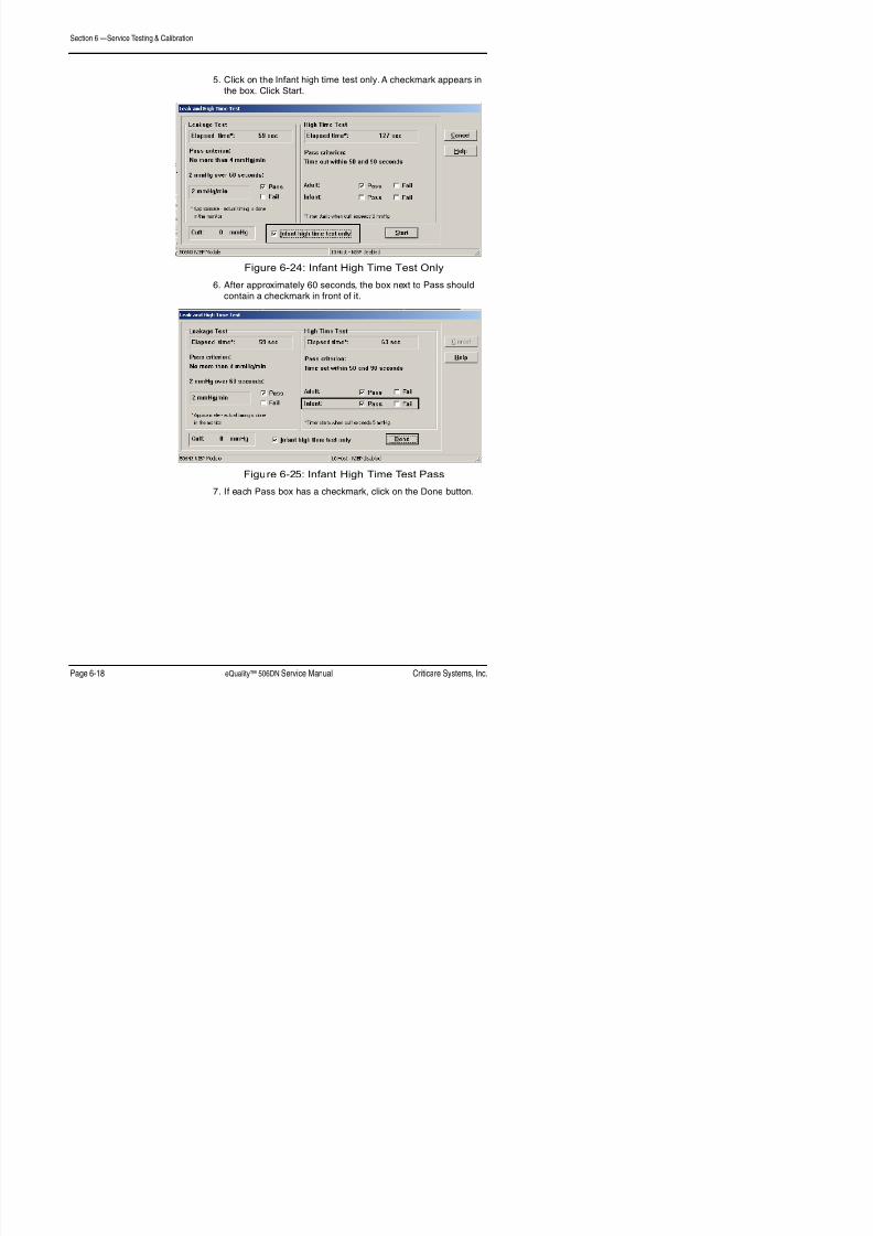
8/22/2019 15 Criticare 506DN - Service Manual
http://slidepdf.com/reader/full/15-criticare-506dn-service-manual 90/125
Figure 6-24: Infant High Time Test Only
6. After approximately 60 seconds, the box next to Pass shouldcontain a checkmark in front of it.
Figure 6-25: Infant High Time Test Pass
7. If each Pass box has a checkmark, click on the Done button.
Section 6 —Service Testing & Calibration
8. The main screen displays checkmarks indicating a Pass of theLeak tests.

8/22/2019 15 Criticare 506DN - Service Manual
http://slidepdf.com/reader/full/15-criticare-506dn-service-manual 91/125
Figure 6-26: Leak Test Pass
Section 6 —Service Testing & Calibration
Accuracy Test 1. Click on Accuracy.

8/22/2019 15 Criticare 506DN - Service Manual
http://slidepdf.com/reader/full/15-criticare-506dn-service-manual 92/125
Figure 6-27: Select Accuracy
2. A Pressure Accuracy Test window appears. Click Start.
Figure 6-28: Pressure Accuracy Test Window
Section 6 —Service Testing & Calibration
3. Check the manometer and the cuff pressure. Pressure willinflate to 70 mmHg. Verify that the pressure is within ±2% or±3 mmHg. If OK click on the Pass box to place a checkmark
in the box. Click Next.

8/22/2019 15 Criticare 506DN - Service Manual
http://slidepdf.com/reader/full/15-criticare-506dn-service-manual 93/125
Figure 6-29: Pressure Accuracy Test, 70 mmHg
4. Repeat for 140 and 280 mmHG.
Figure 6-30: Pressure Accuracy Test, 140 mmHg

8/22/2019 15 Criticare 506DN - Service Manual
http://slidepdf.com/reader/full/15-criticare-506dn-service-manual 94/125
Section 7 — Disassembly
Before You Begin Opening a monitor and breaking the quality seal can void the
manufacturer warranty! Contact the Criticare Service Department
before breaking the seal on any monitor.

8/22/2019 15 Criticare 506DN - Service Manual
http://slidepdf.com/reader/full/15-criticare-506dn-service-manual 95/125
The following procedures are intended to be used by qualified
biomedical engineering or field service personnel for replacement ofPCB assemblies. These procedures are not intended to be used forcomponent-level troubleshooting and repair of the PCB assemblies.
The repair procedures for the 506DN monitor are included here
for the determination of damaged or unusable assemblies. The
manufacturer does not recommend attempting field repair of theprinted circuit boards.
See the 506DN Final Assembly drawing in Section 9.
Service Safety
The following procedures require working with exposed
electrical circuits. Repair should only be attempted byexperienced electronics technicians.
• Do not short circuit the battery terminals! The resulting highcurrent discharge can cause burns.
• Remove the battery before disassembly to avoid electrical shock.
• Electronic components are selected for specific performancecharacteristics. Use of substitute replacement parts y cause
inaccurate performance or damage the monitor. Orderreplacement components by their catalog or part number froman authorized dealer.
• Any time an electrical circuit board is altered through repair oradjustment, it must be fully tested before use.
• Replacement of surface mount components is beyond the
scope of this manual. Attempting to remove surface mountcomponents with a soldering iron can result in the overheating
of the board and damage to tracings. Damaged laminated circuitboards cannot be repaired and require replacement.
WARNING! !
CAUTION! !
Section 7 —Disassembly
Electrostatic DischargeProtection
The procedures in this section require the handling of electrostatic
sensitive components. Microprocessors and other electroniccomponents can be permanently damaged by attempting repairs at
an unprotected workstation.
U ll l t t ti di h (ESD) ti d ib d b l !

8/22/2019 15 Criticare 506DN - Service Manual
http://slidepdf.com/reader/full/15-criticare-506dn-service-manual 96/125
Use all electrostatic discharge (ESD) precautions as described below!
1. Perform the disassembly procedures on an antistatic mat that isgrounded. Check the ground cable to insure that it is connected
to a good earth ground.
2. Always use a grounded soldering iron.
3. Wear a wrist-grounding strap.
4. The wrist strap and mat should both be connected through aresistor (1 mega-ohm typical) to the same ground source.
5. Wrist-ground straps should be tested on a daily basis.
6. Components should be temporarily stored in metal or antistaticcontainers. Never store components in plastic dishes.
7. Circuit boards should be stored in sealed antistatic bags orcovered antistatic boxes. Never store electronic boards directly
in cardboard boxes.
Tools Needed The following is a list of tools needed for disassembly and reassembly
of the eQuality 506DN monitor.
• Set of hand tools
• Up to 7 in. torque screwdriver with accessories
• #10 socket
• 5/16 in. nutdriver
• 1/4 in. nutdriver
Section 7 —Disassembly
Disconnect and
Remove Battery
The battery must be disconnected and removed from the monitor
before any further disassembly of the monitor may be performed.
1. Follow the caution for static-sensitive devices in “Electrostatic
Discharge Protection” on page 7-2.2 O th b tt d b i th t (2)

8/22/2019 15 Criticare 506DN - Service Manual
http://slidepdf.com/reader/full/15-criticare-506dn-service-manual 97/125
2. Open the battery door by unscrewing the two (2) screws
(PHMS #4-40 X .25 GEM Gray; P/N 42745B001) securingit to the back of the monitor.
3. Pull the battery (P/N MISC10004) from the door and disconnectthe battery cables from the terminals.
4. Reassemble in reverse order. Torque to 5 in lbs.
Detach Bezel Assembly
from Housing Assembly
To open the monitor for repairs, detach the bezel assembly from thehousing assembly.
1. Follow the caution for static-sensitive devices in “ElectrostaticDischarge Protection” on page 7-2.
2. Detach the bezel assembly from the housing assembly, removethe four (4) screws (PHMS #6-32 X .50 LG SS; P/N 42435B002)
securing them together.
3. Disconnect the battery cable from J6 the main board (on thebezel assembly).
4. Disconnect the cable from J5 on the main board.
5. Reassemble in reverse order.
• When reattaching the bezel and housing assemblies, make surethe AC and battery cable wires do not get pinched between thetwo assemblies. This will damage the wires.
• Do not allow the battery cable ferrites to coil on the main board.
Reassemble the monitor and perform the “Completion of Service”procedure at the end of this section.
CAUTION! !
Section 7 —Disassembly
Bezel Disassembly
Replace Speaker 1. Follow the caution for static-sensitive devices in “Electrostatic
Discharge Protection” on page 7-2.2 Detach bezel assembly from housing assembly (See “Detach

8/22/2019 15 Criticare 506DN - Service Manual
http://slidepdf.com/reader/full/15-criticare-506dn-service-manual 98/125
2. Detach bezel assembly from housing assembly (See Detach
Bezel Assembly from Housing Assembly” on page 7-3).
3. On the bezel assembly, disconnect the speaker cable J4 from
on the main board.
4. Remove the speaker from the rail on the bezel.
5. Slide the new speaker (P/N 90929A001) under the NIBP
assembly and into the rail ofthe bezel.
Figure 7-1: Reinsert Speaker
6. Connect the speaker cable to the main board at J4.
Reassemble the monitor and perform the “Completion of Service”
procedure at the end of this section.
Rail
Section 7 —Disassembly
Replace LCD Display 1. Follow the caution for static-sensitive devices in “Electrostatic
Discharge Protection” on page 7-2.
2. Detach bezel assembly from housing assembly (See “Detach
Bezel Assembly from Housing Assembly” on page 7-3).3 Detach the PCB/NIBP assembly from the bezel by removing

8/22/2019 15 Criticare 506DN - Service Manual
http://slidepdf.com/reader/full/15-criticare-506dn-service-manual 99/125
3. Detach the PCB/NIBP assembly from the bezel by removing
the two(2) screws (PHMS SEMS #4-40 X .25 LG;P/N 40995B004).
4. Disconnect all of the tubing and remove the connector from P3.
5. On the bezel assembly, disconnect the speaker cable from J4 on the main board.
6. Remove speaker from the rail on the bezel.7. Remove the two (2) screws (PHMS 4-40 X .312 SEMS;
P/N 40995B011) that secure the DOX SpO2 board.
8. Remove the two (2) plastic screws that secure the DOX PCB.
9. Lift and remove the DOX board and insulator.
10.Remove the four (4) screws (PHMS 4-40 X .25 SEMS;P/N 40995B005) that secure the main board.
11.Disconnect the LCD display’s ribbon cable from J1 on themain board.
12.Unlock the membrane tail from J2 on the main board.
13.Lift and remove the main board.
14.Detach LCD display and display shield from the bezel by
removing the four (4) screws (PHMS SEMS #4-40 X .25 LG;P/N 40995B005).
15.Lift the display shield (P/N 83401B002) from the bezel.
16.Remove and replace the LCD display (81521B001).
17.Reassemble in reverse order. See assembly drawings fortorque instructions.
Perform the “Completion of Service” procedure at the end of
this section.
Section 7 —Disassembly
Replace Membrane 1. Follow the caution for static-sensitive devices in “Electrostatic
Discharge Protection” on page 7-2.
2. Detach bezel assembly from housing assembly (See “Detach
Bezel Assembly from Housing Assembly” on page 7-3).3. Unlock the membrane tail from the connector at J2 on the

8/22/2019 15 Criticare 506DN - Service Manual
http://slidepdf.com/reader/full/15-criticare-506dn-service-manual 100/125
3. Unlock the membrane tail from the connector at J2 on the
main board.
4. Remove the old membrane from the bezel.
5. Once removed, clean the bezel with alcohol to remove any
residue from the bezel surface.
6. Obtain a new membrane (P/N 45214B001).
7. Slide the membrane tail through the bezel and remove thepaper backing from the membrane.
8. Place the membrane flush with the bezel and press firmlyaround the bezel to ensure that the membrane is flat and no air
bubbles are apparent.
9. Reassemble in reverse order.
Perform the “Completion of Service” procedure at the end of
this section.
Section 7 —Disassembly
Replace Main Board 1. Follow the caution for static-sensitive devices in “Electrostatic
Discharge Protection” on page 7-2.
2. Detach bezel assembly from housing assembly (See “Detach
Bezel Assembly from Housing Assembly” on page 7-3).3. Detach the NIBP module from the main board by removing the

8/22/2019 15 Criticare 506DN - Service Manual
http://slidepdf.com/reader/full/15-criticare-506dn-service-manual 101/125
y g
two (2) screws (PHMS SEMS #4-40 X .44 LG; P/N 40995B009)located in the lower middle of the main board.
4. Disconnect the NIBP module from the NIBP fitting(P/N 42014B001) on the side panel (P/N 45225B001).
5. Disconnect the NIBP module’s ribbon cable from P3 on themain board.
6. Disconnect the NIBP module’s open tube from the SENS1 connector on the main board.
7. Remove SpO2 board by removing the four (4) screws.
NOTE: Two different types of screws are used to attachthe SpO2 board to the insulator board. The two (2) screws
(PHMS #4-40 X .25 LG, NYLON; P/N 42744B001) on the left
side of the board differ from the two (2) screws (PHMS SEMS#4-40 X .44 LG; P/N 40995B011) on the right side of the board.
8. Detach the insulator board (P/N 42740B001) by breaking the
solder point between the insulator and main boards. (See506DN assembly drawing in Section 9.)
9. Detach the PCB/NIBP assembly from the bezel byremoving the four (4) screws (PHMS SEMS #4-40 X .25 LG;
P/N 40995B005).
10.Unlock the membrane tail from the connector at J2 on themain board.
11.Disconnect the LCD display’s ribbon cable from J1 on themain board.
12.Remove main board from bezel.
13.On the bezel assembly, disconnect the speaker cable from J4 on the main board.
14.Remove the speaker from the rail on the bezel.
15.Remove the two (2) standoffs (STANDOFF M/F #4-40 X .375
LG, NYLON; P/N 42742B001) and two (2) hex nuts (HEX NUT#4-40, NYLON; P/N 42743B001) from the old main board.
Section 7 —Disassembly
16.Obtain a new main board (P/N 91410A001).
17.Reassemble in reverse order. Refer to 506DN assemblydrawing in Section 9 for solder point when connecting the mainand insulator boards.
NOTE: When reassembling, after the NIBP module and SpO2 board
are mounted route the NIBP tube as shown below It must be around

8/22/2019 15 Criticare 506DN - Service Manual
http://slidepdf.com/reader/full/15-criticare-506dn-service-manual 102/125
are mounted, route the NIBP tube as shown below. It must be aroundthe sensor and valves.
Figure 7-2: NIBP Tubing
Perform the “Completion of Service” procedure at the end ofthis section.
Section 7 —Disassembly
Replace DOX SpO2 Board 1. Follow the caution for static-sensitive devices in “Electrostatic
Discharge Protection” on page 7-2.
2. Disconnect and remove the battery from the monitor (See
“Disconnect and Remove Battery” on page 7-3).3. Detach bezel assembly from housing assembly (See “Detach

8/22/2019 15 Criticare 506DN - Service Manual
http://slidepdf.com/reader/full/15-criticare-506dn-service-manual 103/125
Bezel Assembly from Housing Assembly” on page 7-3).
4. Remove old SpO2 board by removing the four (4) screws
holding it to the insulator board.
NOTE: Two different types of screws are used to attach
the SpO2 board to the insulator board. The two (2) screws
(PHMS #4-40 X .25 LG, NYLON; P/N 42744B001) on the leftside of the board differ from the two (2) screws (PHMS SEMS#4-40 X .44 LG; P/N 40995B011) on the right side of the board.
5. Obtain a new SpO2 board (P/N 91391A002).
6. Reassemble in reverse order.
NOTE: When reassembling, after the NIBP module and SpO2 board
are mounted, route the NIBP tube as shown below. It must be around
the sensor and valves.
Figure 7-3: NIBP Tubing
Perform the “Completion of Service” procedure at the end of
this section.
Section 7 —Disassembly
Replace NIBP Module 1. Follow the caution for static-sensitive devices in “Electrostatic
Discharge Protection” on page 7-2.
2. Detach bezel assembly from housing assembly (See “Detach
Bezel Assembly from Housing Assembly” on page 7-3).3. Detach the NIBP module from the main board by removing the
t (2) (PHMS SEMS #4 40 X 44 LG P/N 40995B009)

8/22/2019 15 Criticare 506DN - Service Manual
http://slidepdf.com/reader/full/15-criticare-506dn-service-manual 104/125
two (2) screws (PHMS SEMS #4-40 X .44 LG; P/N 40995B009)located in the lower middle of the main board.
4. Disconnect the NIBP module’s ribbon cable from P3 on themain board.
5. Disconnect the NIBP module’s open tube from the SENS1 connector on the main board.
6. Disconnect the NIBP module from the NIBP fitting(P/N 42014B001) on the side panel (P/N 45225B001).
7. Obtain a new NIBP module (P/N 95597A005).
8. Reassemble in reverse order.
NOTE: When reassembling, after the NIBP module and SpO2 boardare mounted, route the NIBP tube as shown below. It must be around
the sensor and valves.
Figure 7-4: NIBP Tubing
Perform the “Completion of Service” procedure at the end of
this section.
Section 7 —Disassembly
Housing Disassembly
Replace Power Supply 1. Follow the caution for static-sensitive devices in “Electrostatic
Discharge Protection” on page 7-2.2. Detach bezel assembly from housing assembly (See “Detach
Bezel Assembly from Housing Assembly” on page 7 3)

8/22/2019 15 Criticare 506DN - Service Manual
http://slidepdf.com/reader/full/15-criticare-506dn-service-manual 105/125
Bezel Assembly from Housing Assembly on page 7-3).
3. Remove the three (3) screws (PMHS SEMS #4-40 X .25 LG;
P/N 40995B005) holding the insulator (P/N 42740B002) tothe power supply bracket and chassis.
4. Pull out the power supply and bracket and disconnect the powersupply cable (P/N 90927A003) from CON 2 on the power
supply.
5. Disconnect the AC power inlet cable from CON 1 on the
power supply.
6. Disconnect the ground wire from the AC inlet cable fromthe power supply bracket by removing the keps nut(P/N 40284B002).
7. Disconnect the power supply from the bracket (P/N 45213B001)
by removing the four (4) screws (PHMS 4-40 X .438 SEMS;P/N 40995B011) holding them together.
8. Obtain a new power supply (P/N PWRS10000).
9. Reassemble in reverse order. See assembly drawings for
torque instructions.
Perform the “Completion of Service” procedure at the end of
this section.
Section 7 —Disassembly
Completion of Service 1. Verify all connections are secure.
2. Reconnect the battery (See “Disconnect and Remove Battery”on page 7-3).
3. Perform the functional tests in “Functional and Safety Testing”in Section 5.

8/22/2019 15 Criticare 506DN - Service Manual
http://slidepdf.com/reader/full/15-criticare-506dn-service-manual 106/125
4. Perform the electrical safety tests in “Electrical Safety Tests”in Section 5.
Section 8 — Troubleshooting
Troubleshooting Guide
Symptom Problem Solution
Unit won’t power up Battery is discharged Connect AC power cord
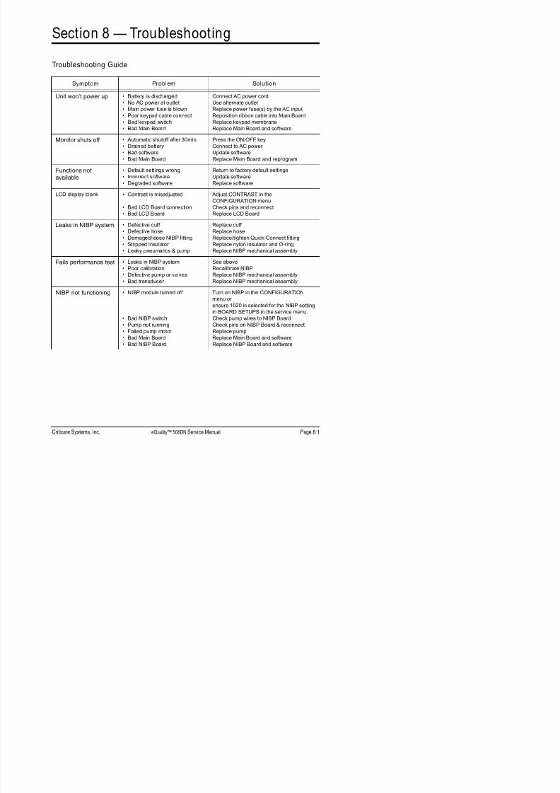
8/22/2019 15 Criticare 506DN - Service Manual
http://slidepdf.com/reader/full/15-criticare-506dn-service-manual 107/125
Unit won’t power up • Battery is discharged
• No AC power at outlet
• Main power fuse is blown
• Poor keypad cable connect
• Bad keypad switch
• Bad Main Board
Connect AC power cord
Use alternate outlet
Replace power fuse(s) by the AC input
Reposition ribbon cable into Main Board
Replace keypad membrane
Replace Main Board and software
Monitor shuts off• Automatic shutoff after 30min.
• Drained battery
• Bad software
• Bad Main Board
Press the ON/OFF key
Connect to AC power
Update software
Replace Main Board and reprogram
Functions not
available
• Default settings wrong
• Incorrect software
• Degraded software
Return to factory default settings
Update software
Replace software
LCD display blank • Contrast is misadjusted
• Bad LCD Board connection• Bad LCD Board
Adjust CONTRAST in the
CONFIGURATION menu
Check pins and reconnectReplace LCD Board
Leaks in NIBP system • Defective cuff
• Defective hose
• Damaged/loose NIBP fitting
• Stripped insulator
• Leaky pneumatics & pump
Replace cuff
Replace hose
Replace/tighten Quick-Connect fitting
Replace nylon insulator and O-ring
Replace NIBP mechanical assembly
Fails performance test • Leaks in NIBP system
• Poor calibration• Defective pump or valves
• Bad transducer
See above
Recalibrate NIBPReplace NIBP mechanical assembly
Replace NIBP mechanical assembly
NIBP not functioning • NIBP module turned off
• Bad NIBP switch
• Pump not running
• Failed pump motor • Bad Main Board
• Bad NIBP Board
Turn on NIBP in the CONFIGURATION
menu or
ensure 1020 is selected for the NIBP setting
in BOARD SETUPS in the service menu.
Check pump wires to NIBP Board
Check pins on NIBP Board & reconnect
Replace pumpReplace Main Board and software
Replace NIBP Board and software
Section 8 —Troubleshooting
SpO2 not functioning. • Using incorrect sensor.
• SpO2
module turned off
Verify the correct sensor is used for the
monitor
Turn on SpO2
in the CONFIGURATION
menu or ensure the proper setting is
selected for the SPO2 setting in BOARD
SETUPS in the service menu
Symptom Problem Solution

8/22/2019 15 Criticare 506DN - Service Manual
http://slidepdf.com/reader/full/15-criticare-506dn-service-manual 108/125
• Bad sensor
• SpO2 board disconnected
• Bad SpO2 board
• Bad Main Board/SpO2 Cable
SETUPS in the service menu.
Replace sensor.
Reconnect SpO2 board
Replace SpO2 board
Replace Main Board/SpO2 Cable
Unit intermittently
missing bloodpressure
measurements
• Cuff size changed
• Wrong cuff size or poor/loose cuffplacement
• Poor connection of NIBP module
• Incorrect Patient Size selected
Unit adapts to cuff size on next attempt
Check cuff selection and placement
Check pins and clean connection of the
NIBP module to the Main Board or replace
module/board if necessary.
Change patient size
No sound fromspeaker
• Speaker wire disconnected
• Speaker wire broken
• Bad Main Board
Reconnect
Replace speaker
Replace Main Board
No communications • Serial settings not correct
• Bad serial cable (external)
• Bad Main Board
Check MENU settings
Replace external serial cable
Replace Main Board
Section 9 —Drawings and Schematics
List of Drawings
Assembly Parts Lists Title Drawing Number
FINAL AY 506DN DOX 93987A001

8/22/2019 15 Criticare 506DN - Service Manual
http://slidepdf.com/reader/full/15-criticare-506dn-service-manual 109/125
NIBP MODULE 6 PIN CONN 95597A005
506DN MONITOR CAT 506DN-X
PCB Drawing List PCB AY DIG SPO2 91391A002
PCB AY DIG SPO2 SCHEMATIC 91391S002506CN MAIN BOARD 91410A001
506DN MAIN BOARD SCHEMATIC 91410S001
Section 9 —Drawings and Schematics
506DN Final Assembly 93987A001 FINAL AY 506DN DOX
Item # CSI Part # Description
01 91410A001 PCB AY, 506CN MAIN BOARD
02 42742B001 STANDOFF M/F #4-40 X .375 LG NYLON03 42743B001 HEX NUT #4-40 NYLON
04 42744B001 P.H.M.S. #4-40 X .25 LG NYLON

8/22/2019 15 Criticare 506DN - Service Manual
http://slidepdf.com/reader/full/15-criticare-506dn-service-manual 110/125
06 42740B002 INSULATOR CHASSIS
07 42740B001 INSULATOR DOX MAIN BRD08 91391A002 PCB AY, DIG SPO2, 506DN09 95597A005 NIBP MODULE 6 PIN CONN
10 45225B001 SIDE PANEL11 42014B001 FITING, QUICK CON. HH NIBP
12 40995B011 P.H.M.S. 4-40 X .438 SEMS13 40284B005 NUT 10-32 KEPS PL
14 45211B001 BEZEL 506CN15 45214B001 MEMBRANE 506CN16 81521B001 DISP/LCD PNL GRAPHIC/320X240
17 42127B004 WINDOW FILTER 506CN18 83401B002 EMI SHIELD
21 40995B005 P.H.M.S. 4-40 X .25 SEMS22 95257A003 SPEAKER CABLE AY 1.5” DIA
23 90929A001 CABLE ASSY BATTERY TO MAIN BRD24 45210B001 HOUSING 506CN25 87277B001 FOOT .50 OD X .19 H
26 40284B001 NUT 4-40 KEPS PL27 83476B001 AC POWER INLET
28 82013B001 FUSE TIME LG 500MA L 250V 5X2029 42064B003 F.H.M.S. 4-40 X .312 PH PL
30 90968A005 CABLE AY AC INLET31 41158B001 TERMINAL EQUIPOTENTIAL
32 41164B001 NUT M6 X 1.0 KEPS PL33 90927A003 CABLE AY POWER SUPPLY TO MAIN BD
34 PWRS10000 PWRSUP 40W 9VDC 90-264VAC 47-63 HZ
35 45213B001 BRACKET POWER SUPPLY
36 83378B001 SHOCK PAD .75DIA X .188TH38 42435B002 P.H.M.S. 6-32 X .375 316SS39 MISC10004 BATT/LA 6V 4.5AH 70X48X110MM
40 45212B001 BATTERY DOOR 506CN41 42745B001 F.H.M.S. #4-40 X .25 COATED GREY
43 40284B002 NUT 6-32 KEPS PL44 40067B001 CABLE TIE 4.0
45 40294B001 HOLDER TIE WRAP ADH-BK SM46 40132B001 TAPE MICROFOAM ADH-BACKED
Section 9 —Drawings and Schematics
NIBP Module 95597A005 NIBP MODULE 6 PIN CONN
Item # CSI Part # Description
01 40067B002 CABLE TIE 5.6
02 40296B002 TUBING SILC BLU .125 X .25003 41700B001 TUBING POLYU .094ID X .187O
04 41579B003 CHECK VALVE

8/22/2019 15 Criticare 506DN - Service Manual
http://slidepdf.com/reader/full/15-criticare-506dn-service-manual 111/125
05 42069B001 TUBING 1/4 X 1/8 POLYU COIL
06 42081B002 ORIFACE RESTRICTOR .012507 42104B003 BRACKET
08 42111B001 SCREW M2-.4X3 PH BINDER09 95576A007 ASSEMBLY PUMP WITH WIRES10 95586A006 AY OKEN VALVE WITH CRIMPS
11 40132B001 TAPE MICROFOAM ADH-BACKED12 41700B002 TUBE POLYU .125 X .250 85DU
13 40324B013 TEE CONNECTOR PLASTIC,.125 X .125 X .125
14 42749B001 FITTING ELBOW 1/8 TO 3/3215 40633B001 FILTER 130U RED NY ELEM
16 87283B003 CONN CBL HSNG JST PHR-66-POS 2MM
17 42750B001 FITTING ELBOW 3/32
18 42751B001 FITTING DBL ELBOW19 40067B001 CABLE TIE 4.0
506DN Moni tor 506DN-X MONITOR SPO2/NIBP (DOX)
Item # CSI Part # Description
01 93987A001 FINAL AY 506DN DOX
02 95795A001 LBL SET 506 DN/CN (ENGLISH)
95795A005 LBL SET 506 DN/CN (SPANISH)03 46426B001 LBL MAIN PRODUCT REV 105 46158B002 LABEL QUAL SEAL OVAL WHT

8/22/2019 15 Criticare 506DN - Service Manual
http://slidepdf.com/reader/full/15-criticare-506dn-service-manual 112/125
1
8
12
(2-PL)5 IN-LBS
3
7
(2-PL)
REVISIONS
REV. DATE DESCRIPTION BY
1 DBLSEE ECN #103089/18/08
2 1/13/09 SEE ECN #10359 DBL

8/22/2019 15 Criticare 506DN - Service Manual
http://slidepdf.com/reader/full/15-criticare-506dn-service-manual 113/125
1049
11 13
(2-PL)5 IN-LBS
5 IN-LBS
2
(2-PL)1 IN-LBS4
NYLONSCREW(2-PL)
9
REV.
SHEETDIST:
PART NO.:
APPR.:MFG.
APPR.:Q.A.
APPR.:
ENG.
WITHOUT WRITTEN CONSENT OF CRITICARE SYSTEMS, INC.
INFORMATION AND MAY NOT BE COPIED OR DIVULGED
CONFIDENTIAL: THIS DOCUMENT CONTAINS CONFIDENTIAL
DO NOT SCALE PRINT
DRAWN
BY:
DATE:
SCALE:
TOLERANCE UNLESSOTHERWISE SPECIFIED:
XX: +/- .020XXX: +/- .005ANGLES: +/- 1 DEGREE
CHECKBY:
RELEASEDATE:
DO NOT SCALE PRINT
TITLE:
21 4
SC
04-04-08
1:1
-
FINAL ASSEMBLY506DN 93987A001
OF
SW
VENDOR SHOULD COMPLY WITH THE FOLLOWING CSI QUALITYREQUIREMENTS: Q1, Q2, Q4, Q5, Q6, Q7,Q10, Q11 A ND Q16.
IN ADDITION THE QUALITY REQUIREMENTS Q9, Q13 AND Q17 APPLY.SEE CSI WEB SITE ( www.csiusa.com/pdf/QA_Requirements.pdf )FOR THE DEFINITION OF THE QUALITY REQUIREMENTS.
CSI #0385 Rev. 0
released Document
17
16
(4-PL)
21(4-PL) 2 IN-LBS
22
REVISIONS
REV. DATE DESCRIPTION BY

8/22/2019 15 Criticare 506DN - Service Manual
http://slidepdf.com/reader/full/15-criticare-506dn-service-manual 114/125
15
14
21
22
(4-PL) 5 IN-LBS
23
PCB / NIBPASSEMBLY(SEE SHT. 1)
18
2
REV.
SHEETDIST:
PART NO.:
APPR.:MFG.
APPR.:Q.A.
APPR.:
ENG.
WITHOUT WRITTEN CONSENT OF CRITICARE SYSTEMS, INC.
INFORMATION AND MAY NOT BE COPIED OR DIVULGED
CONFIDENTIAL: THIS DOCUMENT CONTAINS CONFIDENTIAL
DO NOT SCALE PRINT
DRAWN
BY:
DATE:
SCALE:
TOLERANCE UNLESSOTHERWISE SPECIFIED:
XX: +/- .020XXX: +/- .005ANGLES: +/- 1 DEGREE
CHECKBY:
RELEASEDATE:
DO NOT SCALE PRINT
TITLE:
22 4
SC
04-04-08
1:1
-
FINAL ASSEMBLY506DN 93987A001
OF
SW
VENDOR SHOULD COMPLY WITH THE FOLLOWING CSI QUALITYREQUIREMENTS: Q1, Q2, Q4, Q5, Q6, Q7,Q10, Q11 A ND Q16.
IN ADDITION THE QUALITY REQUIREMENTS Q9, Q13 AND Q17 APPLY.SEE CSI WEB SITE ( www.csiusa.com/pdf/QA_Requirements.pdf )FOR THE DEFINITION OF THE QUALITY REQUIREMENTS.
CSI #0385 Rev. 0
24
12
(4-PL) 5 IN-LBS
21
(3-PL) 5 IN-LBS
27A28 FUSE
31
32
34
35
SEE DETAIL -A-FOR WIRING
30
6
7 IN-LBS
44 45
REVISIONS
REV. DATE DESCRIPTION BY

8/22/2019 15 Criticare 506DN - Service Manual
http://slidepdf.com/reader/full/15-criticare-506dn-service-manual 115/125
25
(SEE NOTE 1)(2-PL) 3 IN-LBS
26
27B
28 FUSE(2-PL)
29
(2-PL) 3 IN-LBS
33
36
BENDTERMINALSUP AS SHOWN
(2-PL)3 IN-LBS
46
CUT 2" LONGX .5" WIDE
43
5 IN-LBS
12 47
NOTES:
1. APPLY LOCTITE (ITEM #47) TO FOOT MOUNTING SCREWS (ITEM #12, 2-PL).
2. USE PROCEDURE 93987PXXX TO ASSEMBLE UNIT.
46
CUT 2" LONG(2-PL)
GNDGRN/YEL(ITEM 24, CABLE AY.)
BRN(ITEM 24)
BLUE(ITEM 24)
27
DETAIL -A-(NTS)
WIRING OF AC INLET
REV.
SHEETDIST:
PART NO.:
APPR.:MFG.
APPR.:Q.A.
APPR.:
ENG.
WITHOUT WRITTEN CONSENT OF CRITICARE SYSTEMS, INC.
INFORMATION AND MAY NOT BE COPIED OR DIVULGED
CONFIDENTIAL: THIS DOCUMENT CONTAINS CONFIDENTIAL
DO NOT SCALE PRINT
DRAWN
BY:
DATE:
SCALE:
TOLERANCE UNLESSOTHERWISE SPECIFIED:
XX: +/- .020XXX: +/- .005ANGLES: +/- 1 DEGREE
CHECKBY:
RELEASEDATE:
DO NOT SCALE PRINT
TITLE:
23 4
SC
04-04-08
1:1
-
FINAL ASSEMBLY596DN 93987A001OF
SW
VENDOR SHOULD COMPLY WITH THE FOLLOWING CSI QUALITYREQUIREMENTS: Q1, Q2, Q4, Q5, Q6, Q7,Q10, Q11 A ND Q16.
IN ADDITION THE QUALITY REQUIREMENTS Q9, Q13 AND Q17 APPLY.SEE CSI WEB SITE ( www.csiusa.com/pdf/QA_Requirements.pdf )FOR THE DEFINITION OF THE QUALITY REQUIREMENTS.
CSI #0385 Rev. 0
BEZEL ASSEMBLY
HOUSING ASSEMBLY
36
APPLY FOAM PADTO BATTERY DOOR
IN THIS APPROXIMATELOCATION 41
(2-PL)
5 IN-LBS
REVISIONS
REV. DATE DESCRIPTION BY

8/22/2019 15 Criticare 506DN - Service Manual
http://slidepdf.com/reader/full/15-criticare-506dn-service-manual 116/125
38 (4-PL) 5 IN-LBS
39
40
48
REV.
SHEETDIST:
PART NO.:
APPR.:MFG.
APPR.:Q.A.
APPR.:
ENG.
WITHOUT WRITTEN CONSENT OF CRITICARE SYSTEMS, INC.
INFORMATION AND MAY NOT BE COPIED OR DIVULGED
CONFIDENTIAL: THIS DOCUMENT CONTAINS CONFIDENTIAL
DO NOT SCALE PRINT
DRAWN
BY:
DATE:
SCALE:
TOLERANCE UNLESSOTHERWISE SPECIFIED:
XX: +/- .020XXX: +/- .005ANGLES: +/- 1 DEGREE
CHECKBY:
RELEASEDATE:
DO NOT SCALE PRINT
TITLE:
24 4
SC
04-04-08
1:1
-
FINAL ASSEMBLY506DN 93987A001
OF
SW
VENDOR SHOULD COMPLY WITH THE FOLLOWING CSI QUALITYREQUIREMENTS: Q1, Q2, Q4, Q5, Q6, Q7,Q10, Q11 A ND Q16.
IN ADDITION THE QUALITY REQUIREMENTS Q9, Q13 AND Q17 APPLY.SEE CSI WEB SITE ( www.csiusa.com/pdf/QA_Requirements.pdf )FOR THE DEFINITION OF THE QUALITY REQUIREMENTS.
CSI #0385 Rev. 0
10 V1
V2
CONNECTORHOUSING
PUMP AY
VALVE AY(2-PL)
9
(3 4)
6
1
RED - PUMP +
BLK - PUMP -
16
WHT V2
WHT V1
REVISIONS
REV. DATE DESCRIPTION BY

8/22/2019 15 Criticare 506DN - Service Manual
http://slidepdf.com/reader/full/15-criticare-506dn-service-manual 117/125
FINISHED ASSEMBLY
(4-PL)(TORQUE
TO 2 IN LBS)
TO V1
123
7
16
6.00"LONG
.50"LONG
.75"LONG
.75"LONG
6
115
2
4
1
1.00"LONG1.50"
LONG
.75"LONG
(2-PL)
INSTALL WITHARROW POINTING
AWAY FROMPUMP
13
V2
TO V2
CONNECTORHOUSING
87283B003(JST PHR-6)
CONNECTOR WIRING DETAIL
NOTES:
1. REFER TO ASSEMBLY PROCEDURE FOR 95597P005 ASSEMBLY SEQUENCE AND INSTRUCTIONS.
3
17
3 18 3
14
3
12
1.25" LONG
1.50" LONG
8
1.00"LONG
5
.75"LONG
15
19
BLK (2)
RED (1)
(3,4)
(5,6)
REV.
SHEETDIST:
PART NO.:
APPR.:MFG.
APPR.:Q.A.
APPR.:
ENG.
WITHOUT WRITTEN CONSENT OF CRITICARE SYSTEMS, INC.
INFORMATION AND MAY NOT BE COPIED OR DIVULGED
CONFIDENTIAL: THIS DOCUMENT CONTAINS CONFIDENTIAL
DO NOT SCALE PRINT
DRAWN
BY:
DATE:
SCALE:
TOLERANCE UNLESSOTHERWISE SPECIFIED:
XX: +/- .020XXX: +/- .005ANGLES: +/- 1 DEGREE
CHECKBY:
RELEASEDATE:
DO NOT SCALE PRINT
TITLE:
01 1
SC
04-04-08
1:1
-
NIBP MODULE6 PIN CONN 95597A005
OF
SW
VENDOR SHOULD COMPLY WITH THE FOLLOWING CSI QUALITYREQUIREMENTS: Q1, Q2, Q4, Q5, Q6, Q7,Q10, Q11 AND Q16.
IN ADDITION THE QUALITY REQUIREMENTS Q9, Q13 AND Q17 APPLY.SEE CSI WEB SITE ( www.csiusa.com/pdf/QA_Requirements.pdf )FOR THE DEFINITION OF THE QUALITY REQUIREMENTS.
CSI #0385 Rev. 0
released Document
2D
2C
2H
2B
2G
2K
2F
LABELNIBP/SPO2
LABELFRONT LOGO
LABELMODEL
LABELELEC. RATING
LABELCOUNTRY
OF ORIGIN
LABELREGULATORY
LABELMODEL/SERIAL NO.
2L LABELLANGUAGE MENU
REVISIONS
REV. DATE DESCRIPTION BY
1 DBLSEE ECN #103591/14/09

8/22/2019 15 Criticare 506DN - Service Manual
http://slidepdf.com/reader/full/15-criticare-506dn-service-manual 118/125
2E
2A
2J
1
LABELSERIAL PORT
LABEL
WARNINGS
LABELBATTERYINSTALL
(NOT USED ON ENGLISH VERSION)
3
REVISIONLABEL
NOTES:
1. NOT SHOWN:
ITEM #4, SHIPPING ASSEMBLY (PACKAGING)
ITEM #5, 46036B101 CSI LOGO QUALITY SEAL LABEL
REV.
SHEETDIST:
PART NO.:
APPR.:MFG.
APPR.:Q.A.
APPR.:
ENG.
WITHOUT WRITTEN CONSENT OF CRITICARE SYSTEMS, INC.
INFORMATION AND MAY NOT BE COPIED OR DIVULGED
CONFIDENTIAL: THIS DOCUMENT CONTAINS CONFIDENTIAL
DO NOT SCALE PRINT
DRAWN
BY:
DATE:
SCALE:
TOLERANCE UNLESSOTHERWISE SPECIFIED:
XX: +/- .020XXX: +/- .005ANGLES: +/- 1 DEGREE
CHECK
BY:
RELEASEDATE:
DO NOT SCALE PRINT
TITLE:
11 1
SC
04-10-08
NTS
-
MONITORNIBP, WITH DOX/SQL SPO2 CAT 506XN-XOF
SW
VENDOR SHOULD COMPLY WITH THE FOLLOWING CSI QUALITYREQUIREMENTS: Q1, Q2, Q4, Q5, Q6, Q7,Q10, Q11 AND Q16.
IN ADDITION THE QUALITY REQUIREMENTS Q9, Q13 AND Q17 APPLY.SEE CSI WEB SITE ( www.csiusa.com/pdf/QA_Requirements.pdf )FOR THE DEFINITION OF THE QUALITY REQUIREMENTS.
CSI #0385 Rev. 0

8/22/2019 15 Criticare 506DN - Service Manual
http://slidepdf.com/reader/full/15-criticare-506dn-service-manual 119/125
released Document

8/22/2019 15 Criticare 506DN - Service Manual
http://slidepdf.com/reader/full/15-criticare-506dn-service-manual 120/125

8/22/2019 15 Criticare 506DN - Service Manual
http://slidepdf.com/reader/full/15-criticare-506dn-service-manual 121/125

8/22/2019 15 Criticare 506DN - Service Manual
http://slidepdf.com/reader/full/15-criticare-506dn-service-manual 122/125
released Document

8/22/2019 15 Criticare 506DN - Service Manual
http://slidepdf.com/reader/full/15-criticare-506dn-service-manual 123/125

8/22/2019 15 Criticare 506DN - Service Manual
http://slidepdf.com/reader/full/15-criticare-506dn-service-manual 124/125

8/22/2019 15 Criticare 506DN - Service Manual
http://slidepdf.com/reader/full/15-criticare-506dn-service-manual 125/125