equality™ 506dn vital signs monitor service manual...criticare systems, inc. equality 506dn...
TRANSCRIPT

Cat. No. 1557Date 01/09
Part No. 39184B101Revision 0
eQuality™ 506DN Vital Signs Monitor
Service Manual
Page ii eQuality™ 506DN Service Manual Criticare Systems, Inc.
Copyright
COPYRIGHT © CRITICARE SYSTEMS, INC., 2009
CRITICARE SYSTEMS, INC. (Criticare) owns all rights to this unpublished work and intends to maintain this work as confidential. Criticare may also seek to maintain this work as an unpublished copyright. This publication is to be used solely for the purposes of reference, operation, maintenance, or repair of Criticare equipment. No part of this publication may be reproduced in any manner or disseminated for other purposes.
In the event of inadvertent or deliberate publication, Criticare intends to enforce its rights to this work under copyright laws as a published work. Those having access to this work may not copy, use, or disclose the information in this work unless expressly authorized by Criticare to do so.
All product specifications, as well as information contained in this publication, are subject to change without notice.
All information contained in this publication is believed to be correct. Criticare Systems, Inc., shall not be liable for errors contained herein nor for incidental or consequential damages in connection with the furnishing, performance, or use of this material.
This publication may refer to information and products protected by copyrights or patents and does not convey any license under the patent rights of Criticare Systems, Inc., nor the rights of others. Criticare Systems, Inc., does not assume any liability arising out of any infringements of patents or other rights of third parties.
PROPERTY OF CRITICARE SYSTEMS, INC.ALL RIGHTS RESERVED
eQuality™ Vital Signs Monitor, DOX™ Digital Oximetry, ComfortCuff™ NIBP and Multi-Site™ SpO2 Sensors are trademarks of Criticare Systems, Inc.
Criticare Systems, Inc. eQuality™ 506DN Service Manual Page iii
ContentsCopyright................................................................................................................ iiContents................................................................................................................ iiiWarranty............................................................................................................... viiService Return Policy.......................................................................................... viiiEC Declaration of Conformity................................................................................ ix
Section 1 – Introduction
Description .................................................................................................................... 1-1Intended Use................................................................................................................. 1-1Non-Invasive Blood Pressure (NIBP)............................................................................ 1-2
ComfortCuff® Technology ................................................................................. 1-2Description of NIBP Measurement..................................................................... 1-2NIBP Clinical Testing and Accuracy................................................................... 1-3Cuff Inflation and Pressure Protection ............................................................... 1-3
Heart Rate..................................................................................................................... 1-4DOX™ Pulse Oximetry Measurement (SpO2) .............................................................. 1-5
Definition ............................................................................................................ 1-5DOX™ Digital Oximetry ..................................................................................... 1-5Method ............................................................................................................... 1-5SpO2 Clinical Testing and Accuracy .................................................................. 1-6
Specifications................................................................................................................ 1-7Symbols ...................................................................................................................... 1-10Safety.......................................................................................................................... 1-12
Software Error Related Hazard Mediation ....................................................... 1-14Potential Interference....................................................................................... 1-14Leakage Current .............................................................................................. 1-14Voltage Fluctuations......................................................................................... 1-15Equipotential Ground ....................................................................................... 1-15Defibrillation, HF, and Electronic Device Protection......................................... 1-15Biocompatibility ................................................................................................ 1-15Latex Content................................................................................................... 1-15DEHP Content.................................................................................................. 1-15
Section 2 – Service Menus
Introduction ................................................................................................................... 2-1Service Mode ................................................................................................................ 2-1
Service Mode Window ....................................................................................... 2-1Service Menus .............................................................................................................. 2-2
Revisions Menu.................................................................................................. 2-2Test Menu .......................................................................................................... 2-3Default Setups.................................................................................................... 2-4Board Setups ..................................................................................................... 2-5
NIBP Calibration Menu ................................................................................................. 2-6Setting User Defaults .................................................................................................... 2-7
Setting User Defaults ......................................................................................... 2-7Power Up in Service Mode................................................................................. 2-7
Page iv eQuality™ 506DN Service Manual Criticare Systems, Inc.
Contents
Factory Defaults ............................................................................................................2-9Main Menu..........................................................................................................2-9Alarm Menu ........................................................................................................2-9Configuration Menu ..........................................................................................2-10Communication Menu.......................................................................................2-10Patient Data Menu............................................................................................2-11NIBP Cycle Menu .............................................................................................2-11
Main Menu...................................................................................................................2-12Patient Size ......................................................................................................2-12Alarm Volume...................................................................................................2-12Pulse Volume ...................................................................................................2-12Enable MAP......................................................................................................2-12
Alarm Menu.................................................................................................................2-13High Pulse ........................................................................................................2-13Low Pulse .........................................................................................................2-13High SpO2 ........................................................................................................2-13Low SpO2 .........................................................................................................2-13High Systolic.....................................................................................................2-14Low Systolic......................................................................................................2-14High Diastolic....................................................................................................2-14Low Diastolic ....................................................................................................2-14High MAP .........................................................................................................2-14Low MAP ..........................................................................................................2-14
Configuration Menu.....................................................................................................2-15Time..................................................................................................................2-15Hour..................................................................................................................2-15Minute...............................................................................................................2-15Day ...................................................................................................................2-15Month................................................................................................................2-15Year ..................................................................................................................2-15Contrast ............................................................................................................2-15Brightness.........................................................................................................2-15Reverse Video..................................................................................................2-15NIBP .................................................................................................................2-15SpO2.................................................................................................................2-15Units .................................................................................................................2-15Language..........................................................................................................2-15
Communication Menu .................................................................................................2-16On NIBP ...........................................................................................................2-16On Alarm ..........................................................................................................2-16Interval..............................................................................................................2-16Patient Data......................................................................................................2-16Print To .............................................................................................................2-16Serial ................................................................................................................2-16Baud Rate.........................................................................................................2-16
Patient Data.................................................................................................................2-17Weight ..............................................................................................................2-17Height ...............................................................................................................2-17Respiration .......................................................................................................2-17Pain ..................................................................................................................2-17
Section 3 – Theory of Operation
System Architecture ......................................................................................................3-1Module Architecture ......................................................................................................3-2
Main Board .........................................................................................................3-2NIBP Module ......................................................................................................3-2DOX SpO2 Module .............................................................................................3-2
Block Diagram...............................................................................................................3-3
Criticare Systems, Inc. eQuality™ 506DN Service Manual Page v
Contents
Section 4 – Cleaning and Disinfecting
Cleaning and Disinfecting ............................................................................................. 4-1Pulse Oximeter Sensors .................................................................................... 4-1Blood Pressure Cuffs ......................................................................................... 4-2
Accidental Wetting ........................................................................................................ 4-3
Section 5 – Preventative Maintenance
Incoming Inspection ...................................................................................................... 5-1Maintenance Schedule ................................................................................................. 5-1Long-Term Storage....................................................................................................... 5-1Disposal ........................................................................................................................ 5-1Service Checks ............................................................................................................. 5-2Calibration..................................................................................................................... 5-2Serviceable Components.............................................................................................. 5-3
Battery Removal/Replacement .......................................................................... 5-3Fuse Removal/Replacement.............................................................................. 5-5
Annual Testing .............................................................................................................. 5-6Accessory Testing.............................................................................................. 5-6Functional and Safety Testing............................................................................ 5-6Equipment and Tools ......................................................................................... 5-7Test Fixtures ...................................................................................................... 5-8
Electrical Safety Tests ................................................................................................ 5-10Withstanding Voltage Test (Hi-pot) .................................................................. 5-10Equipment Needed .......................................................................................... 5-10Setup Hi-pot Tester .......................................................................................... 5-10Hi-pot Performance Test .................................................................................. 5-11Leakage Testing............................................................................................... 5-11Setup Procedure (Self-Test) ............................................................................ 5-11Leakage Procedure.......................................................................................... 5-12
Functional Tests.......................................................................................................... 5-14System Check .................................................................................................. 5-14Speaker Performance, Alarms Verification ...................................................... 5-15Power Supply Performance ............................................................................. 5-15
Monitoring Module Verification.................................................................................... 5-16NIBP Verification .............................................................................................. 5-16NIBP Seal Test................................................................................................. 5-17SpO2 Verfication .............................................................................................. 5-18
Functional and Safety Testing Checklist..................................................................... 5-19
Section 6 – Service Testing & Calibration
Monitor Testing ............................................................................................................. 6-1Service Checks .................................................................................................. 6-1
Field Service Testing .................................................................................................... 6-1Equipment and Tools ......................................................................................... 6-2
Communication Testing ................................................................................................ 6-3Equipment Required .......................................................................................... 6-3Pinout Chart ....................................................................................................... 6-3Procedure........................................................................................................... 6-3Nurse Call .......................................................................................................... 6-4
DOX SpO2 Performance Testing .................................................................................. 6-5Programming the SmartSat Analyzer................................................................. 6-5Test Procedure................................................................................................... 6-5

Page vi eQuality™ 506DN Service Manual Criticare Systems, Inc.
Contents
NIBP Calibration............................................................................................................6-6Equipment Required...........................................................................................6-6Installing the PC Service Program......................................................................6-6Configuring the Ports..........................................................................................6-6Setup ..................................................................................................................6-7Calibrate .............................................................................................................6-9Safety Test .......................................................................................................6-11Speed Test .......................................................................................................6-14Leak Test..........................................................................................................6-16Accuracy Test...................................................................................................6-20
Section 7 – Disassembly
Before You Begin ..........................................................................................................7-1Service Safety ....................................................................................................7-1Electrostatic Discharge Protection......................................................................7-2Tools Needed .....................................................................................................7-2
Disconnect and Remove Battery...................................................................................7-3Detach Bezel Assembly from Housing Assembly .........................................................7-3Bezel Disassembly ........................................................................................................7-4
Replace Speaker ................................................................................................7-4Replace LCD Display .........................................................................................7-5Replace Membrane ............................................................................................7-6Replace Main Board ...........................................................................................7-7Replace DOX SpO2 Board .................................................................................7-9Replace NIBP Module ......................................................................................7-10
Housing Disassembly..................................................................................................7-11Replace Power Supply .....................................................................................7-11
Completion of Service .................................................................................................7-12
Section 8 – Troubleshooting
Troubleshooting Guide ..................................................................................................8-1
Section 9 – Drawings and Schematics
List of Drawings.............................................................................................................9-1Assembly Parts Lists ..........................................................................................9-1PCB Drawings List..............................................................................................9-1
506DN Final Assembly..................................................................................................9-2NIBP Module .................................................................................................................9-3506DN Monitor ..............................................................................................................9-3

Criticare Systems, Inc. eQuality™ 506DN Service Manual Page vii
Warranty
Workmanship & Materials
Criticare Systems, Inc. (CSI) warranties new equipment to be free from defects in workmanship and materials for a period of two (2) years from date of shipment under normal use and service. The 940 Series Multi-Site™ Sensor carries a six month warranty. CSI’s obligation under this warranty is limited to repairing or replacing, at CSI’s option, any part which upon CSI’s examination proves defective.
EXCEPT AS DESCRIBED IN THE PARAGRAPH ABOVE, CSI MAKES NO WARRANTIES, EXPRESS OR IMPLIED, INCLUDING ANY WARRANTY OF MERCHANTABILITY OR FITNESS FOR A PARTICULAR PURPOSE.
Exemptions CSI’s obligation or liability under this warranty does not include any transportation or other charges or liability for direct, indirect or consequential damages or delay resulting from the improper use or application of the product or the substitution upon it of parts or accessories not approved by CSI or repair by anyone other than a CSI authorized representative.
This warranty shall not extend to any instrument which has been subjected to misuse, negligence or accident; any instrument from which CSI’s original serial number tag or product identification markings have been altered or removed; or any product of any other manufacturer.
Safety, Reliability & Performance
Criticare Systems, Inc. is not responsible for the effects on safety, reliability and performance of the 506DN Patient Monitor if: assembly operations, extensions, readjustments, modifications or repairs are carried out by persons other than those authorized by Criticare Systems, Inc., or
the 506DN Patient Monitor is not used in accordance with the instructions for use, or
the electrical installation of the relevant room does not comply with NFPA 70: National Electric Code or NFPA 99: Standard for Health Care Facilities (Outside the United States, the relevant room must comply with all electrical installation regulations mandated by the local and regional bodies of government).
In Case of Emergency Contact
CRITICARE SYSTEMS, INC. Telephone: (262) 798-828220925 Crossroads Circle Tech Support: (800) 458-2697Suite 100 Orders: (800) 458-4615Waukesha, WI 53186 Fax: (262) 798-8290USA
Internet: www.csiusa.com

Page viii eQuality™ 506DN Service Manual Criticare Systems, Inc.
Service Return Policy
Return Procedure In the event that it becomes necessary to return a unit to Criticare Systems, Inc., the following procedure should be followed:
Obtain return authorization. Contact the CSI Service Department at 800-458-2697 to obtain a Customer Service Authorization (CSA) number. (Outside the US, call 001-262-798-8282.) The CSA number must appear on the outside of the shipping container. Return shipments will not be accepted if the CSA number is not clearly visible. Please provide the model number, serial number, and a brief description of the reason for return.
Freight policy. The customer is responsible for freight charges when equipment is shipped to CSI for service (this includes customs charges).
Loaner service. In the U.S. If it is necessary to provide a loaner system, CSI will ship a loaner by overnight courier. The loaner system must be returned to CSI at the customer’s expense within one week after receipt of the repaired goods. If the unit is not returned to CSI within that time, the customer will be invoiced for the full purchase price of the equipment.
Outside the U.S. No loaners are available from CSI internationally. Contact your local CSI representative.
Incoming Inspection The following incoming inspection is required whether it is a first time arrival or a return from service. Prior to clinical use, the instrument should be inspected for the following.
1. The quality inspection seal on the instrument should be unbroken. This seal indicates that the instrument has been tested according to manufacturers specifications.
2. No physical damage is observed.
3. The instrument's battery is to be charged by connecting the instrument to a power outlet for a minimum of 6 hours prior to clinical use.
4. When connecting the instrument to a power outlet and then turning the instrument on, all displays appear to function correctly and no system errors occur.
If a discrepancy to these inspection items is observed, do not use the instrument and immediately report the discrepancy to the CSI Service Department.

Criticare Systems, Inc. eQuality™ 506DN Service Manual Page ix
EC Declaration of Conformity
eQuality™ 506DN Patient Monitor
To view the Declaration of Conformity, visit the Criticare website at www.csiusa.com. A copy of the Declaration can also be faxed. Contact Criticare’s customer service department at (262) 798-8282 to obtain a faxed copy of the Declaration.
Representative in the European Union
Criticare Systems Limitedc/o Wright Hassall9 Clarendon PlaceLeamington SpaWarwickshireCV 32 5QP – United Kingdom
T: 0044 (0) 1926 886688F: 0044 (0) 1926 885588
For the Attention of: Ref. 45 (or) Mr. L. A. Heizler

Criticare Systems, Inc. eQuality™ 506DN Service Manual Page 1-1
Section 1 — Introduction
Description The 506DN patient monitor is a compact vital signs monitor that measures heart rate, blood oxygen saturation (SpO2) and non-invasive blood pressure (NIBP). Heart rate is measured primarily by the plethysmographic waveform but when the oximeter is not is use, heart rate is determined from the blood pressure data using an oscillometric method that measures during inflation.
Intended Use The 506DN monitor is intended to monitor physiological parameters of patients within clinical care settings and can be used in transport. It is intended that the user is a professional health care provider. Physiological data, systems alarms, and patient data analysis are available to the care provider from the monitor.
The user is responsible for the interpretation of the monitored data that is made available. Physiological data should be reviewed by qualified clinical personnel prior to any medical intervention.
The monitor is designed to be used with only one patient at a time. The monitor (including accessories) is capable of monitoring a full range of patients from neonate to adult.
Section 1 —Introduction
Page 1-2 eQuality™ 506DN Service Manual Criticare Systems, Inc.
Non-Invasive Blood Pressure (NIBP)
The 506DN monitor uses ComfortCuff® technology to determine non-invasive blood pressure by means of oscillometry. The oscillometric method detects volume displacements within the artery and senses pressure variations within the blood pressure cuff during inflation. The monitor uses cuffs ranging in size from neonate cuffs to adult thigh cuffs.
ComfortCuff® Technology ComfortCuff technology measures NIBP while the cuff inflates. Consequently, a measurement is obtained more quickly and with less discomfort than with monitors, which measure NIBP during cuff deflation.
Description of NIBPMeasurement
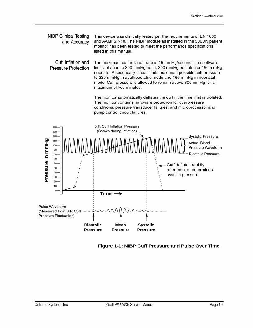
The NIBP cuff begins to inflate at the beginning of the NIBP measurement cycle. As the cuff pressure approaches the diastolic pressure of the patient, the cuff pressure waveform begins to indicate the pulse waveform. The cuff pressure at this point is equal to the patient’s diastolic pressure, which is stored by the monitor.
As cuff pressure continues to increase, the pulse waveform (as measured from BP cuff pressure fluctuation) becomes stronger reaching its maximum at the patient’s mean arterial pressure (i.e., when cuff pressure = mean BP). The monitor stores this value as mean pressure.
As cuff pressure increases further, it approaches the patient’s systolic pressure, and the cuff’s pulse waveform decreases in amplitude. The cuff pulse waveform disappears at the point where cuff pressure is equal to the patient’s systolic pressure.
When the monitor determines that the cuff waveform has decreased to zero amplitude, it stores the cuff pressure value as the systolic pressure, and releases the pressure from the cuff. This typically occurs at about 10 mmHg over the patient’s systolic pressure. The cuff then rapidly deflates.
Dynamic Measurement Ranges
Systolic (mmHg) Diastolic (mmHg) MAP (mmHg)
Adult 50-280 30-225 35-245
Pediatric 50-280 30-225 35-245
Neonate 50-135 20-100 30-120
Criticare Systems, Inc. eQuality™ 506DN Service Manual Page 1-3
Section 1 —Introduction
NIBP Clinical Testingand Accuracy
This device was clinically tested per the requirements of EN 1060 and AAMI SP-10. The NIBP module as installed in the 506DN patient monitor has been tested to meet the performance specifications listed in this manual.
Cuff Inflation andPressure Protection
The maximum cuff inflation rate is 15 mmHg/second. The software limits inflation to 300 mmHg adult, 300 mmHg pediatric or 150 mmHg neonate. A secondary circuit limits maximum possible cuff pressure to 330 mmHg in adult/pediatric mode and 165 mmHg in neonatal mode. Cuff pressure is allowed to remain above 300 mmHg for a maximum of two minutes.
The monitor automatically deflates the cuff if the time limit is violated. The monitor contains hardware protection for overpressure conditions, pressure transducer failures, and microprocessor and pump control circuit failures.
Figure 1-1: NIBP Cuff Pressure and Pulse Over Time
Pre
ssur
e in
mm
Hg
B.P. Cuff Inflation Pressure(Shown during inflation)
Time
Pulse Waveform(Measured from B.P. CuffPressure Fluctuation)
Systolic Pressure
Diastolic Pressure
Actual BloodPressure Waveform
Cuff deflates rapidlyafter monitor determinessystolic pressure
DiastolicPressure
MeanPressure
SystolicPressure
Section 1 —Introduction
Page 1-4 eQuality™ 506DN Service Manual Criticare Systems, Inc.
Heart Rate Heart rate measurement is determined primarily by the plethysmographic (SpO2) waveform. When the oximeter is not in use, heart rate is determined from the blood pressure data by using an oscillometric method that measures during inflation. The unit of measurement is beats per minute.
Under conditions where the plethysmographic based heart rate and oscillometric heart rate are both beyond the detectable limits of the monitor, no heart rate is reported. Also, no heart rate is reported where the amplitude of the plethysmograhic waveform and oscillometric waveform are beyond the detectable limits. The monitor reports error messages if valid measurements cannot be obtained. The monitor continues to look for valid SpO2 based heart rate measurements and attempts a second NIBP measurement if the first attempt fails.

Criticare Systems, Inc. eQuality™ 506DN Service Manual Page 1-5
Section 1 —Introduction
DOX™ Pulse Oximetry Measurement (SpO2)
The 506DN patient monitor comes with Digital Oximetry (DOX) technology to measure blood oxygen saturation (SpO2).
Definition Hemoglobin exists in the blood in several forms:
• Oxygenated (Oxyhemoglobin)
• Reduced (Deoxyhemoglobin)
• Dsyhemoglobins (Carboxyhemoglobin and Methemoglobin)
In the monitor, SpO2 (pulse arterial saturation) is the ratio of oxygenated hemoglobin to the sum of oxygenated hemoglobin plus hemoglobin which is available for binding to oxygen, as expressed in the following formula:
Dyshemoglobins, such as carboxyhemoglobin and methemoglobin, are not directly measured and therefore are not factored into the measurement.
DOX™ Digital Oximetry The monitor does not use analog circuitry for signal processing. Digital signal processing in the microprocessor results in lower noise from circuitry components, resulting in a cleaner signal and better performance under low perfusion conditions. There is also improved rejection of noise from the patient and environment, due to the availability of the “true,” unfiltered sensor signal for digital signal processing.
Method The digital pulse oximeter measures oxygen saturation and pulse rate using the principles of spectrophotometry and plethysmography. The sensor is completely non-invasive, and there is no heat source that could burn the patient.
The pulse oximeter sensor contains two types of LEDs. Each type emits a specific wavelength of light. Since oxygenated hemoglobin and deoxygenated hemoglobin absorb light selectively and predictably, the amounts of these two compounds can be determined by measuring the intensity of each wavelength that passes through the measuring site.
percent oxygen saturation = x 100oxyhemoglobinoxyhemoglobin + deoxyhemoglobin
Section 1 —Introduction
Page 1-6 eQuality™ 506DN Service Manual Criticare Systems, Inc.
The light from the LEDs shines into a pulsating vascular bed. A photodetector located opposite of alongside the LEDs measures the intensity of each wavelength transmitted through the monitoring site. The light intensity is converted to an electrical signal, which is input to the monitor. The effects of skin pigmentation, venous blood, and other tissue constituents are eliminated by separating out the average pulsating absorption data.
SpO2 is calculated with every pulse and averaged with the results from previous pulses to arrive at the current numeric display value. The display is updated at least once per second with the numeric values that were calculated during the intervening period.
The plethysmographic pulse wave is not auto-gained. The amplitude display of the plethysmographic pulse is proportionalto the pulse volume changes occurring in the tissue illuminated by the SpO2 sensor.
SpO2 Clinical Testingand Accuracy
All Criticare oximeter’s (DOX-compatible) have SpO2 calibration tables which were originally generated by monitoring desaturated human patients or volunteers and matching their displayed SpO2 value to the value determined by sampling arterial blood and measuring functional SaO2 with a clinical laboratory grade multi wavelength optical oximeter (i.e., CO-oximeter). The final SpO2 calibration curve was then generated based upon numerous patients’ data over the range of 40 to 99% SaO2. All accepted data were taken from patients with dyshemoglobin (i.e., carboxyhemoglobin or methemoglobin) concentrations near zero.
This oximeter is a two-wavelength device, which is calibrated to measure functional SpO2 only when dyshemoglobin concentrations are near zero. The accuracy specifications of this device will not be met with high concentrations of dyshemoglobins. Significant concentrations of carboxyhemoglobin results is a higher displayed SpO2 value than is actually present in the patient.
SpO2 clinical accuracy validation to CO-oximeter SaO2 readings was performed for the sensors using a DOX-compatible monitor.
The personal demographics of the study participants for the SpO2 clinical accuracy validation include a mix of adult males and females from 18 to 45 years of age. All were healthy during the course of the study. Physical characteristics and skin tone were by chance with a mix from slight to stout and light to dark. Clinical testing for neonatal participants was conducted per U.S. FDA recommended clinical protocols.
Criticare Systems, Inc. eQuality™ 506DN Service Manual Page 1-7
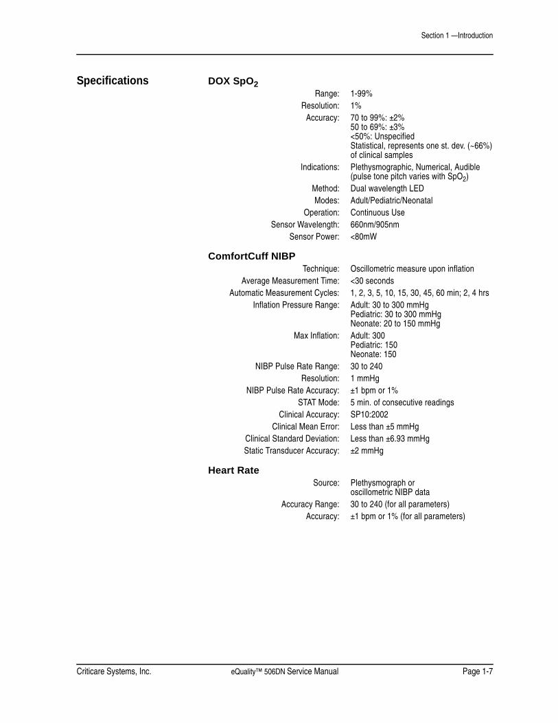
Section 1 —Introduction
Specifications DOX SpO2 Range: 1-99%
Resolution: 1%Accuracy: 70 to 99%: ±2%
50 to 69%: ±3%<50%: UnspecifiedStatistical, represents one st. dev. (~66%)of clinical samples
Indications: Plethysmographic, Numerical, Audible(pulse tone pitch varies with SpO2)
Method: Dual wavelength LEDModes: Adult/Pediatric/Neonatal
Operation: Continuous UseSensor Wavelength: 660nm/905nm
Sensor Power: <80mW
ComfortCuff NIBPTechnique: Oscillometric measure upon inflation
Average Measurement Time: <30 secondsAutomatic Measurement Cycles: 1, 2, 3, 5, 10, 15, 30, 45, 60 min; 2, 4 hrs
Inflation Pressure Range: Adult: 30 to 300 mmHgPediatric: 30 to 300 mmHgNeonate: 20 to 150 mmHg
Max Inflation: Adult: 300Pediatric: 150Neonate: 150
NIBP Pulse Rate Range: 30 to 240Resolution: 1 mmHg
NIBP Pulse Rate Accuracy: ±1 bpm or 1%STAT Mode: 5 min. of consecutive readings
Clinical Accuracy: SP10:2002Clinical Mean Error: Less than ±5 mmHg
Clinical Standard Deviation: Less than ±6.93 mmHgStatic Transducer Accuracy: ±2 mmHg
Heart RateSource: Plethysmograph or
oscillometric NIBP dataAccuracy Range: 30 to 240 (for all parameters)
Accuracy: ±1 bpm or 1% (for all parameters)
Section 1 —Introduction
Page 1-8 eQuality™ 506DN Service Manual Criticare Systems, Inc.
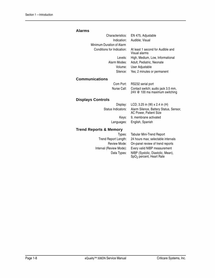
AlarmsCharacteristics: EN 475, Adjustable
Indication: Audible; VisualMinimum Duration of Alarm
Conditions for Indication: At least 1 second for Audible andVisual alarms
Levels: High, Medium, Low, InformationalAlarm Modes: Adult, Pediatric, Neonate
Volume: User AdjustableSilence: Yes; 2 minutes or permanent
CommunicationsCom Port: RS232 serial port
Nurse Call: Contact switch; audio jack 3.5 mm,24V @ 100 ma maximum switching
Displays ControlsDisplay: LCD; 3.25 in (W) x 2.4 in (H)
Status Indicators: Alarm Silence, Battery Status, Sensor,AC Power, Patient Size
Keys: 9, membrane activatedLanguages: English, Spanish
Trend Reports & MemoryTypes: Tabular Mini-Trend Report
Trend Report Length: 24 hours max; selectable intervalsReview Mode: On-panel review of trend reports
Interval (Review Mode): Every valid NIBP measurementData Types: NIBP (Systolic, Diastolic, Mean),
SpO2 percent, Heart Rate
Criticare Systems, Inc. eQuality™ 506DN Service Manual Page 1-9
Section 1 —Introduction
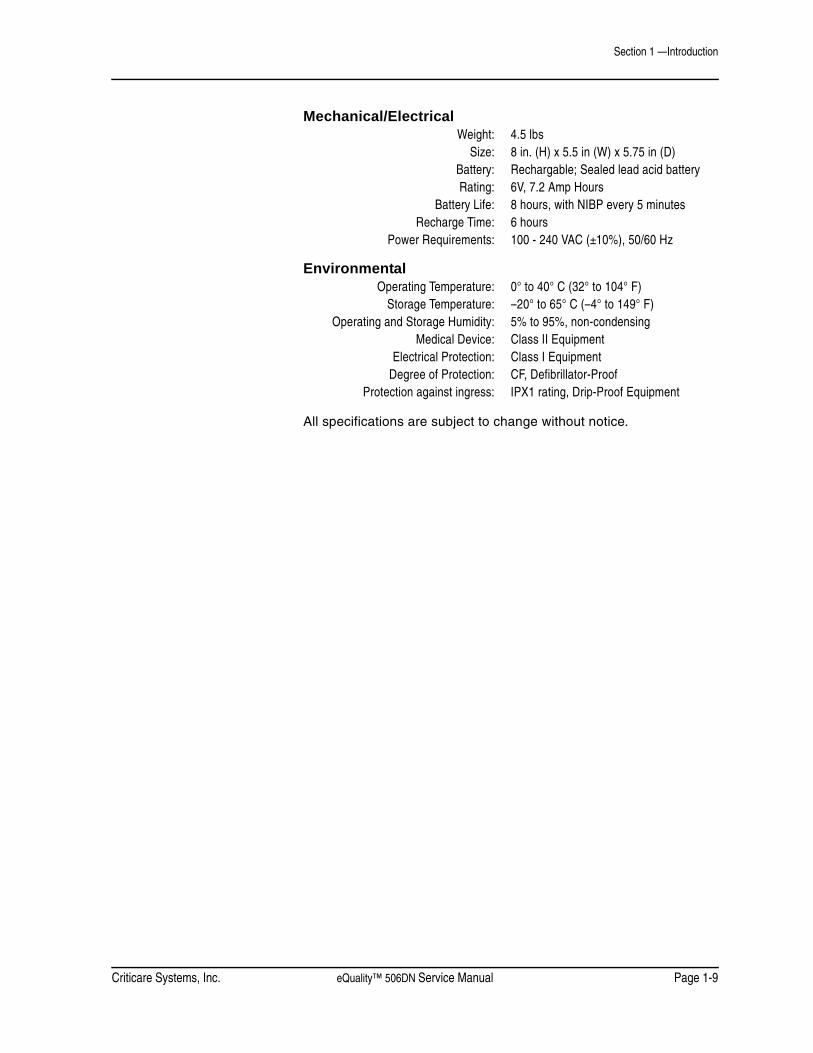
Mechanical/ElectricalWeight: 4.5 lbs
Size: 8 in. (H) x 5.5 in (W) x 5.75 in (D)Battery: Rechargable; Sealed lead acid batteryRating: 6V, 7.2 Amp Hours
Battery Life: 8 hours, with NIBP every 5 minutesRecharge Time: 6 hours
Power Requirements: 100 - 240 VAC (±10%), 50/60 Hz
EnvironmentalOperating Temperature: 0° to 40° C (32° to 104° F)
Storage Temperature: –20° to 65° C (–4° to 149° F)Operating and Storage Humidity: 5% to 95%, non-condensing
Medical Device: Class II EquipmentElectrical Protection: Class I Equipment
Degree of Protection: CF, Defibrillator-ProofProtection against ingress: IPX1 rating, Drip-Proof Equipment
All specifications are subject to change without notice.

Section 1 —Introduction
Page 1-10 eQuality™ 506DN Service Manual Criticare Systems, Inc.
Symbols Symbol Definition
Refer to Operator’s Manual for Information
Shock Hazard
Equipotential Terminal
European Community Mark of Approval
Electrical Testing Laboratories (ETL) Mark
Identifies the degree of protection against fluid as drip proof
Type CF Equipment, defib proof
Do not dispose of in municipal waste. Wheeled bin symbol indicates separate collection for electrical and electronic equipment (WEEE Directive 2002/96/EEC)
Alternating Current (AC)
Fuse
Technical Support Phone Number
IPX1

Criticare Systems, Inc. eQuality™ 506DN Service Manual Page 1-11
Section 1 —Introduction
Symbol Definition
Non-Invasive Blood Pressure, Connection
SpO2 Sensor Mounting, Connection
Communication Transmit/Receive Port
Not a Sensor Connection
Alarm Port (Nurse Call)
Serial Number
Part Reference Number
Placement of cuff over the brachial artery.(Blood Pressure Cuff)
Single use device only. Do not reuse.
Recycle cardboard/paper packaging.
SN
REF
2

Section 1 —Introduction
Page 1-12 eQuality™ 506DN Service Manual Criticare Systems, Inc.
Safety Definitions for Warning and Caution symbols:
Designates a possible dangerous situation. Non-observance may lead to death or the most severe injuries.
Designates a possible dangerous situation. Non-observance may lead to minor injuries or damage to the product.
NOTE: Indicates that important information follows, a tip that can help you recover from an error, or point you to related details in the manual.
• Read this manual entirely before attempting clinical use of the monitor.
• A possible explosion hazard exists! Do not use this monitor in the presence of flammable anesthetics.
• Cables, cords, and leadwires may present a risk of entanglement or strangulation! Verify safe and proper positioning of these items after patient application.
• Unapproved modifications to the monitor may cause unexpected results and present a hazard to the patient.
• Risk of electrical shock! Do not remove cover. Refer servicing to qualified personnel.
• U.S. Federal law restricts this device to sale by or on the order of a physician.
WARNING ! !
CAUTION ! !
WARNING ! !
Criticare Systems, Inc. eQuality™ 506DN Service Manual Page 1-13
Section 1 —Introduction
• Use the monitor only with recommended accessories! Use of unapproved accessories may cause inaccurate readings.
• Equipment accuracy may be affected at extreme temperatures.
• Do not store equipment at extreme temperature. Temperatures exceeding specified storage temperatures could damage the system.
• Do not press on the keys with surgical instruments or other tools. Sharp or hard objects could damage the keys. Use only your fingertips to press on the keys.
• Changes or modifications not expressly approved by Criticare Systems, Inc., may void the user’s authority to operate the equipment and may also void the warranty.
• Setting alarm limits to extreme values may render the alarm system useless.
• A functional tester cannot be used ti assess the accuracy of a pulse oximeter probe or pulse oximeter monitor. If there is independent demonstration that a particular calibration curve is accurate for the combination of a pulse oximeter monitor and a pulse oximeter probe, then a functional tester can measure the contribution of a monitor to the total error of a monitor/probe system. The functional tester can then measure how accurately a particular pulse oximeter monitor is reproducing that calibration curve.
CAUTION ! !

Section 1 —Introduction
Page 1-14 eQuality™ 506DN Service Manual Criticare Systems, Inc.
Software Error RelatedHazard Mediation
Criticare Systems, Inc., has quality control practices and procedures in place to review potential hazards as they relate to software.
The monitor is Year 2000 Compliant and utilizes a 4 digit year for all date, time and leap year calculations.
Potential Interference This device has been successfully tested to IEC 601-1-2 specified levels for emissions of and resistance to electromagnetic energy fields. External disturbances which exceed these levels may cause operational issues with this device. Other devices which are sensitive to a lower level of emissions than those allowed by IEC 601-1-2 may experience operational issues when used in proximity to this device.
MAGNETIC FIELDSUse of the monitor in an MRI environment may interfere with MRI image quality. Use of MRI may interfere with the monitor.
The 506DN patient monitor is not intended for use in MRI environments.
RADIO FREQUENTLY INTERFERENCEThe monitor conforms with IEC 61000-4-3 for radio frequency interference, and will operate with negligible effects.
CONDUCTED TRANSIENTSThe monitor conforms to IEC 61000-4-4, and IEC 61000-4-5 for conducted transients, and will operate with negligible adverse effects.
X-RAYThe monitor will operate with negligible adverse effects in an X-ray environment. However, the monitor should not be placed directlyin the x-ray beam, which could damage the internal electronics of the monitor.
OTHER INTERFERENCEThere is a negligible adverse effect to the monitor from electrocautery, electrosurgery, infrared energy, pacemakers,or defibrillation.
Leakage Current The monitor complies with leakage current limits required by medical safety standards for patient-connected devices. Standards include the International Electrotechnical Commission (IEC) 60601-1, 2nd edition, 1988 Part 1. A hazard caused by the summation of leakage currents is possible, when several pieces of equipment are interconnected.

Criticare Systems, Inc. eQuality™ 506DN Service Manual Page 1-15
Section 1 —Introduction
Voltage Fluctuations The monitor is suitable for connection to AC (mains) voltage as defined by EN 61000-3-3 and EN 61000-4-11. When operated in the line voltage range specified in this manual any fluctuation will have a negligible effect. Very low line voltage will cause the monitor to revert to battery power. Very high line voltage will cause damage to the charger circuits. The monitor is designed with circuitry that will turn the unit off before spurious readings can be caused by a low battery connection.
Equipotential Ground Health care providers and patients are subject to dangerous, uncontrollable compensating currents for electrical equipment. These currents are due to the potential differences between connected equipment and touchable conducting parts found in medical rooms..
Defibrillation, HF, andElectronic Device
Protection
The monitor when used with its recommended accessories is protected against the effects of the discharge of a defibrillator and the use of HF electrosurgical equipment. The monitor presents no known adverse effects to pacemakers or other medical safety equipment.
Biocompatibility All patient-contact or user-contact materials in this monitor and its accessories have passed ISO 10993-5, -10 and -11 biocompatibility tests of have been in use in clinical environments in large numbers over an extended period of time predating these standards.
Latex Content All Criticare Systems, Inc., products, including patient monitors and accessories, are free from latex in any location that may result in patient contact.
DEHP Content All Criticare Systems, Inc., products currently shipping are free of DBP and DEHP in any areas that would be intended for patient contact with blood, mucous membranes, or continuous skin and/or tissue contact.
Connection Lead (Socket)
Equipotential Connector
Equipotential Terminal
Main Body
Earth Ground


Criticare Systems, Inc. eQuality™ 506DN Service Manual Page 2-1
Section 2 — Service Menus
Introduction There is one primary service boot that uses the DOWN arrow at power up takes the monitor into Service Mode. A secondary service boot uses the NIBP START/STAT/STOP key at power up and takes the monitor into NIBP Calibration Mode. These service software tools allow downloading of software upgrades for the 506DN operating system and for calibration of the NIBP module in the field.
To exit the SERVICE MENU power cycle the monitor.
Service Mode
Service Mode Window
Figure 2-1: 506DN Service Mode Window
• Never service a monitor while it is attached to a patient.
• Never enter the service menu while monitoring a patient.
SERVICE DISPLAYREVISIONSTEST MENUDEFAULT SETUPSBOARD SETUPS
WARNING ! !

Section 2 —Service Menus
Page 2-2 eQuality™ 506DN Service Manual Criticare Systems, Inc.
Service Menus The Service Menu is displayed when the DOWN ARROW is held when during power up and no upgrade tool is attached the external serial port.
The Service Menu contains four submenus:
• Revisions
• Test Menu
• Default Setups
• Board Setups
These submenus are accessed by using the arrow keys and then pressing the MENU key when the desired menu is highlighted.
Revisions Menu The revisions menu contains the revisions of the software and module components. Exit the REVISIONS menu by pressing and holding the MENU key. The monitor will return to the main service menu.
Figure 2-2: 506DN Revisions Menu
REVISIONS
506CN/506DN SERIES REVISION 1.0HAPP. CS.: 31EDAUG 21 2008SN 999999999SPO2 DOX 1.3AHW REV. 00

Criticare Systems, Inc. eQuality™ 506DN Service Manual Page 2-3
Section 2 —Service Menus
Test Menu The TEST MENU contains the monitor’s NIBP Seal self test.
Figure 2-3: 506DN Test Menu
To perform the NIBP SEAL self test:
1. Press the MENU key to shift the cursor to OFF.
2. Press the either arrow key to change OFF to ON.
3. Press the MENU key to begin the test.
The following message will appear.
“START” TO SEALXXXX.X mmHg
The valves close so that the pneumatic circuit can be checked for leaks. This provides a simple field test for verifying the safety and static pressure accuracy of the NIBP transducer.
The current pressure is displayed on the second line of the message displayed on the LCD screen. All pressures from 0 to 300 mmHg have an accuracy of ±2%. The message format allows for the display of negative numbers to indicate negative zero offsets.
Press the MENU key a second time to terminate the test.
TEST MENU NIBP SEAL OFF

Section 2 —Service Menus
Page 2-4 eQuality™ 506DN Service Manual Criticare Systems, Inc.
Default Setups The DEFAULT SETUPS menu contains options for setting the default values which will take effect when the monitor is turned on with the MENU key pressed and held during power up.
Figure 2-4: 506DN Defaults Setup Menu
CONFIG USERThis selects the which type of configuration defaults are restored following a MENU power up. Choices are USER, HOSP. (hospital), and ALT C. (alternate care).
STORE USERThis allows the monitor’s current configuration settings to be stored as the USER defaults. The options for this setting are Yes and No.
Pressing the MENU key with Yes selected causes the CONFIRM setting to become available. Select Yes for CONFIRM to store the current settings as the user defaults.
AUDIO OFFThis selects the nature of the Alarm Volume setting of OFF in the ALARMS MENU. Choosing Yes indicates true silencing of the audio alarm. Choosing No causes the audio not to annunciate alarms but sounds a double beep every two minutes for verification that the audio circuit still functions.
LINE FREQUENCYThe monitor has a 60 Hz setting for domestic U.S. use and a 50 Hz setting for international use. The frequency must be set correctly to the local AC (Mains) power frequency for the monitor to function correctly. Contact the local CSI distributor for more information about which setting to use.
DEFAULT SETUPS
CONFIG DEF USERSTORE USER NOCONFIRM NOAUDIO OFF YESLINE FREQ 60

Criticare Systems, Inc. eQuality™ 506DN Service Manual Page 2-5
Section 2 —Service Menus
Board Setups The BOARD SETUPS menu provides settings for the monitoring modules installed on the monitor.
Figure 2-5: 506DN Board Setups Menu
SPO2Selects which type of SpO2 module is installed in the monitor. Choices are DOX and SEQL (SEQUEL).
NIBPSelects which type of NIBP module is installed in the monitor. Choices are 1020 (ComfortCuff) and None.
DOWNLOADUse this menu item to download software. Choices are None, DOX, 1020 (ComfortCuff), and Main. Selecting a processor will cause the monitor to search for a software download tool.
Software downloads are sent to the monitor by opening the software file on an external computer and sending the application to the monitor via the COM1port.
BOARD SETUPS
SPO2 DOXNIBP 1020DOWNLOAD NONE

Section 2 —Service Menus
Page 2-6 eQuality™ 506DN Service Manual Criticare Systems, Inc.
NIBP Calibration Mode To enter the NIBP Calibration mode:
1. Press the POWER key and the NIBP/START/STAT/STOP key at the same time.
2. The 506DN monitor attempts to connect to extended NIBP calibration tools through the external serial port, identifying itself as a 506DN monitor.
3. The message CHECKING FOR NIBP TOOLS... should appear in the LCD message bar.
A service calibration application, called NIBP SERVICE (pn 97082A003), may be run on a connected PC. See “NIBP Calibration” in Section 6 for testing details.
Criticare Systems, Inc. eQuality™ 506DN Service Manual Page 2-7
Section 2 —Service Menus
Setting User Defaults This is a default setting profile that can be set for a facility’s special needs. The user defaults are initially set to the same settings as the HOSP (hospital) defaults. User defaults setup should be performed by qualified personnel.
Setting User Defaults A facility can save setting in USER default setting. Once the settings are made, the settings can be saved under a USER setting profile on the monitor.
To set user defaults:
1. Power up the monitor.
2. Press the MENU key to access the MAIN MENU.
3. Use the MENU and ARROW keys to access the different submenus and adjust the settings for each patient size.
NOTE: It is not possible for to store USER defaults for LOW SPO2 below 85%, NIBP ON/OFF, SPO2 ON/OFF, and LANGUAGE. Each of the ignored user defaults is controlled independently of the USER default settings. LOW SPO2 returns to a default value of 85% if the current setting is below 85%.
4. Verify all settings are correct and power off the monitor.
Power Up in Service Mode The monitor needs to be powered up in the Service Mode to finish setting the user defaults. To power up the monitor in Service Mode:
1. While holding the DOWN arrow key, press the ON/OFF (power) key.
2. Continue holding the DOWN arrow key until SERVICE DISPLAY menu appears on the LCD display.

Section 2 —Service Menus
Page 2-8 eQuality™ 506DN Service Manual Criticare Systems, Inc.
3. Use the arrow keys to highlight DEFAULT SETUPS and press the MENU key to enter the Default Setups Menu.
Figure 2-6: Select Default Setups4. Use the arrow keys to highlight STORE USER and press the
MENU key to move the cursor to the Store User settings.
Figure 2-7: Select STORE USER5. Select YES and press the MENU key.
The CONFIRM submenu item now becomes active. Use the arrow keys to select YES and press the MENU key to confirm the new User Default settings.
6. The new User Default settings are now saved on the monitor.
SERVICE DISPLAYREVISIONSTEST MENUDEFAULT SETUPSBOARD SETUPS
DEFAULT SETUPS
CONFIG DEF USERSTORE USER NOCONFIRM NOAUDIO OFF YESLINE FREQ 60

Criticare Systems, Inc. eQuality™ 506DN Service Manual Page 2-9
Section 2 —Service Menus
Factory Defaults To recall factory defaults from memory, hold the MENU key while you press the POWER key to turn on the monitor. Settings affect the MAIN MENU, ALARM, CONFIGURATION, COMMUNICATION, PATIENT DATA, and the NIBP CYCLE Menus.
NOTE: The Main Menu and Alarm, Configuration, Communication, and Patient Data submenus are all accessed through the MENU key on the front panel. The NIBP Cycle Menu is entered through the NIBP CYCLE key on the front panel.
Main Menu
Alarm Menu
‡ The monitor returns a minimum low value of 85 on power up.
* Mean values only appear if MAP is enabled in the main menu.
Setting Options Factory Default ValuesSize Adult, Pediatric (Ped.),
Neonate (Neo.)Adult
Alarm Volume 1 to 10, OFF 4Pulse Volume 1 to 10, OFF OFFEnable MAP ON, OFF ON
Alarm Type Range Hospital Alternate CarePulse Rate High 80 to 240, OFF 150 (Adult)
150 (Pediatric)180 (Neonate)
150 (Adult)150 (Pediatric)180 (Neonate)
Pulse Rate Low 20 to 150, OFF 40 (Adult)40 (Pediatric)90 (Neonate)
40 (Adult)40 (Pediatric)90 (Neonate)
SpO2 High 70 to 98, OFF OFF (Adult)OFF (Pediatric)OFF (Neonate)
OFF (Adult)OFF (Pediatric)OFF (Neonate)
SpO2 Low 1 to 98, OFF 90 ‡ (Adult)90 ‡ (Pediatric)90 ‡ (Neonate)
90 ‡ (Adult)90 ‡ (Pediatric)90 ‡ (Neonate)
NIBP Systolic High 75 to 240, OFF 200 (Adult)200 (Pediatric)140 (Neonate)
200 (Adult)200 (Pediatric)140 (Neonate)
NIBP Systolic Low 50 to 150, OFF 50 (Adult)50 (Pediatric)50 (Neonate)
50 (Adult)50 (Pediatric)50 (Neonate)
NIBP Diastolic High 50 to 180, OFF 100 (Adult)100 (Pediatric)80 (Neonate)
100 (Adult)100 (Pediatric)80 (Neonate)
NIBP Diastolic Low 15 to 50, OFF 30 (Adult)30 (Pediatric)30 (Neonate)
40 (Adult)40 (Pediatric)30 (Neonate)
NIBP Mean High 70 to 200, OFF 150 (Adult)150 (Pediatric)100 (Neonate)
OFF * (Adult)OFF * (Pediatric)OFF * (Neonate)
NIBP Mean Low 25 to 125, OFF 50 (Adult)50 (Pediatric)40 (Neonate)
OFF * (Adult)OFF * (Pediatric)OFF * (Neonate)

Section 2 —Service Menus
Page 2-10 eQuality™ 506DN Service Manual Criticare Systems, Inc.
Configuration Menu
† The monitor returns to this setting on power up.
N/A This setting does not have a factory default value.
* This setting is only available after a MENU power up.
Communication Menu
Setting OptionsHospital Default
ValueAlternate Care Default Value
Time 24-Hour, AM/PM 24-Hour AM/PMHour 0 - 23 N/A N/AMinute 0 - 59 N/A N/ADay 1 - 31 N/A N/AMonth JAN - DEC N/A N/AYear 00 - 99 N/A N/AContrast 5 - 95 % 70 % 70 %Brightness 5 - 95 % 50 % 50 %NIBP Tone None, Begin, End, Both None NoneReverse Video ON, OFF OFF OFFNIBP ON. OFF ON † ON †SpO2 ON, OFF ON † ON †
Units English, Metric English EnglishLanguage * English, Spanish N/A N/A
Setting Options Factory Default ValuePrint on NIBP ON, OFF ONPrint on alarm ON, OFF OFFInterval Spot; BPT;
1, 2, 5, 10, 15, 30, 60 minutes2, 4, 8, 12, 24 hours; OFF
OFF
Patient Data ON, OFF OFFPrint To Serial, OFF SerialSerial Text, CSV, CUSP, OFF TextBaud Rate 2400, 4800, 9600, 19200, 38400 19200
Criticare Systems, Inc. eQuality™ 506DN Service Manual Page 2-11
Section 2 —Service Menus
Patient Data Menu
NIBP Cycle Menu
NOTE: The NIBP CYCLE menu is accessed using the NIBP CYCLE key located on the front panel. All other default settings are accessed using the MENU key with the UP/DOWN keys.
Setting Options Factory Default Value Weight 2 - 500 lbs 100 lbsHeight 5 - 100 in 60 inRespiration 1 to 99 /min 20 /minPain 1 to 10 1
Setting Options Factory Default Value NIBP Cycle 1, 2, 3, 5 10, 15, 30, 45, 60 minutes;
2 or 4 hours; OffOff

Section 2 —Service Menus
Page 2-12 eQuality™ 506DN Service Manual Criticare Systems, Inc.
Main Menu Press the MENU key to enter the Main Menu. Use the arrow keys to select the main settings and submenus and press the MENU key to access them. Use the arrow and MENU keys to change settings as desired.
Patient Size The patient size can be set to Adult, Pediatric (Ped.) and Neonate (Neo.).
Alarm Volume The alarm volume can be set from 1 to 10 and off. If the volume is set to off or 1 it returns to 2 if the monitor is power cycled. The factory default is 4.
Pulse Volume The pulse volume can be set from 1 to 10 and off. The pulse volume setting will remain if the monitor is power cycled.
Enable MAP The NIBP MAP display can be turned on and off in the main menu.

Criticare Systems, Inc. eQuality™ 506DN Service Manual Page 2-13
Section 2 —Service Menus
Alarm Menu Press the MENU key to enter the Main Menu. Use the arrow keys to highlight ALARM MENU and press the MENU key to access it.
Use the arrow keys to move through the alarm submenu and highlight the setting you desire to change. Press the MENU key to access the settings for the desired item. When the setting is changed as desired, press the MENU key to save the setting.
Alarm limits are set separately for adult, pediatric, and neonatal modes and are saved independently.
To set adult alarm limits, enter the ALARM MENU while in adult mode. Patient size mode is set in the Main Menu. Confirm that “ADULT” appears in the bottom right corner of the display. Set all desired alarm limits for adult monitoring conditions.
Change the patient size to pediatric and set all desired alarm limits for pediatric monitoring conditions.
Change the patient size to neonate and set all desired alarm limits for neonate monitoring conditions.
High Pulse Select the high alarm limit for pulse rate. Choices are 80 through 240 bpm and off. Resolution is 2 bpm. The factory default value is 40 for Adult and Pediatric modes and 180 for Neonate mode.
Low Pulse Select the low alarm limit for pulse rate.Choices are 20 through150 bpm and off. Resolution is 2 bpm. The factory default value is 40 for Adult and Pediatric modes and 90 for Neonate mode.
High SpO2 Select the high alarm limit for SpO2. Choices are 70 through 98% and off. The resolution is 1% blood oxygen saturation. The factory default is off for all patient size modes.
Low SpO2 Select the low alarm limit for SpO2. Choices are 1 through 98% and off. The factory default value is 90% for all patient size modes.
If Low SpO2 is set to 98%, the High SpO2 alarm may not be changed from the off setting.
The Low SpO2 setting returns to a minimum value of 85% after a power cycle.

Section 2 —Service Menus
Page 2-14 eQuality™ 506DN Service Manual Criticare Systems, Inc.
High Systolic Select the high alarm limit for systolic blood pressure. Choices are 75 through 240 mmHg and off. The factory default value is 200 for Adult and Pediatric modes and 140 for Neonate mode.
Low Systolic Select the low alarm limit for systolic blood pressure. Choices are 50 through 150 mmHg and off. The factory default value is 50 for all patient modes.
High Diastolic Select the high alarm limit for diastolic blood pressure. Choices are 50 through 180 mmHg and off. The factory default value is 100 for Adult and Pediatric modes and 80 for Neonate mode.
Low Diastolic Select the low alarm limit for diastolic blood pressure. Choices are 15 through 50 mmHg an off. The factory hospital default is 30 for all patient size modes. The factory alternate care default is 40 for Adult and Pediatric modes and 30 for Neonate mode.
High MAP Select the high alarm limit for mean arterial blood pressure. Choices are 70 through 200 mmHg and off. The factory hospital default value is 150 for Adult and Pediatric modes and 100 for Neonate mode. The factory alternate care default value is off for all patient size modes.
Low MAP Select the low alarm limit for mean arterial blood pressure. Choices are 25 through125 mmHg and off. The factory hospital default value is 50 for Adult and Pediatric modes and 40 for Neonate mode. The factory alternate care default value is off for all patient size modes.

Criticare Systems, Inc. eQuality™ 506DN Service Manual Page 2-15
Section 2 —Service Menus
Configuration Menu Press the MENU key to enter the Main Menu. Use the arrow keys to highlight CONFIGURATION and press the MENU key to access it.
Use the arrow keys to move through the configuration submenu and highlight the setting you desire to change. Press the MENU key to access the settings for the desired item. When the setting is changed as desired, press the MENU key to save the setting.
Time Sets the monitor time to 24-Hour or AM/PM. The hospital default is 24-Hour. The alternate care default is AM/PM.
Hour Set the current hour. Hour is always set in 24-hour format to establish the correct AM/PM time.
Minute Sets the current minute.
Day Sets the current day.
Month Sets the current month.
Year Sets the current year.
Contrast Adjusts the LCD display from 5% to 95% in 5% increments. The contrast changes as the adjustment is made. The factory default value is 70%.
Brightness Adjusts the LCD brightness from 5% to 95% in 5% increments. The brightness changes as the adjustment is made. The factory default value is 50%.
Reverse Video The LCD display can be set to reverse video. The factory default value is Off.
NIBP Turns the NIBP function On or Off. This automatically resets to On when restarting the monitor.
SpO2 Turns the SpO2 function On or Off. This automatically resets to On when restarting the monitor.
Units The monitor can display units in English and Metric. The factory default is English.
Language The monitor has language settings available in English and Spanish. The monitor must be restarted before the language setting change activates.
NOTE: This setting is only available after a MENU power up.

Section 2 —Service Menus
Page 2-16 eQuality™ 506DN Service Manual Criticare Systems, Inc.
Communication Menu Press the MENU key to enter the Main Menu. Use the arrow keys to highlight COMMUNICATION and press the MENU key to access it.
Use the arrow keys to move through the communication submenu and highlight the setting you desire to change. Press the MENU key to access the settings for the desired item. When the setting is changed as desired, press the MENU key to save the setting.
On NIBP The monitor prints data when an NIBP reading is taken. Choices are On or Off. The factory default setting is Off.
On Alarm The monitor prints data during a medium or high level alarm limit violation. Choices are On or Off. The factory default value is Off.
Interval This sets the time interval for automatic interval printing of vital signs data. Choices are 10, 20 or 30 seconds; 1, 2, 5, 10, 15, 30, or 60 minutes; 2, 4, 8, 12, or 24 hours; and Off. The factory default value is Off.
Patient Data Selecting On causes the patient data to print when a demand print is requested.
Print To Sets the output device of the monitor. Choices are Serial and Off. The factory default value is Serial.
Serial Sets the data format for the external serial port (for sending data to an external device). The choices are Text, CSV, CUSP, and Off. The factory default value is Text.
Baud Rate Sets the baud rate of the monitor. The choices are 2400, 4800, 9600, 19200, and 38400. The factory default value is 19200.

Criticare Systems, Inc. eQuality™ 506DN Service Manual Page 2-17
Section 2 —Service Menus
Patient Data Press the MENU key to enter the Main Menu. Use the arrow keys to highlight PATIENT DATA and press the MENU key to access it.
Use the arrow keys to move through the patient data submenu and highlight the setting you desire to change. Press the MENU key to access the settings for the desired item. When the setting is changed as desired, press the MENU key to save the setting.
Weight Sets the patient’s weight.
Height Sets the patient’s height.
Respiration Sets the patient’s respiration rate.
Pain Sets the patient’s pain level.


Criticare Systems, Inc. eQuality™ 506DN Service Manual Page 3-1
Section 3 — Theory of Operation
System Architecture The 506DN monitor’s circuitry consists of a Main Board, LCD Module, SpO2 Module, and NIBP Module.
The Main Board, SpO2 Module and NIBP Module are considered the Main Module. This module is located in the monitor’s font bezel. The LCD display mounts to the main board, which in turn mounts to the front bezel.
Affixed to the front bezel is the membrane switch and overlay that connects directly to the main board.
The rear housing contains the 6-Volt lead acid battery and AC-to-DC Power Supply.
The lead acid battery is contained in a compartment accessible with a tool. The design of the compartment prevents the 506DN circuitry from being exposed when the battery compartment is opened. Thus the 506DN does not require recalibration or functional testing due to a possible tampering of critical electronics.
External connectors consist of:
• An RS-232 COM port
• AC (Mains) Power
• NIBP ComfortCuff (pneumatic)
• SpO2 Sensor
Electrical isolation of patient connections observes EN60601-1. On this end, isolated DC power supplies are contained by the DOX SpO2 technology. Additional isolation is incorporated through a medical grade AC-to-DC power supply conforming to 4000VAC isolation and an isolated supply for the external COM function. This supply conforms to 4000VAC isolation.

Section 3 —Theory of Operation
Page 3-2 eQuality™ 506DN Service Manual Criticare Systems, Inc.
Module Architecture
Main Board(pn 91410A001)
The hardware design of the 506DN monitor relies on multiple serial communication channels wherein the Main Board functions as the hub. Signal and display processing is off-loaded to the various vital signs technology modules, the Display Board, and the LCD Module. The Main Board collects the vital signs information, then stores, formats, and outputs the data either electronically through the external serial port or in hardcopy via the optional internal printer module.
There is a power supply section of the Main Board wherein regulated DC voltages are generated for various logic and analog functions as well as the battery charging function.
NIBP Module(pn 95597A005)
This module connects to the Main Board. The upgraded NIBP algorithm firmware installed conforms to EN1060.
DOX SpO2 Module(pn 91391A002)
This module is the Criticare Digital Oximetry circuit. The DOX Module provides electrical isolation of 1500VAC minimum through power and serial interface connections. The DOX SpO2 sensor connector is mounted directly onto the Module.
Criticare Systems, Inc. eQuality™ 506DN Service Manual Page 3-3
Section 3 —Theory of Operation
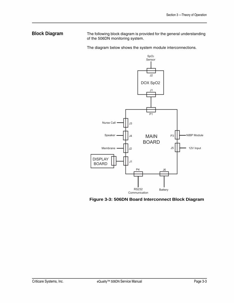
Block Diagram The following block diagram is provided for the general understanding of the 506DN monitoring system.
The diagram below shows the system module interconnections.
Figure 3-3: 506DN Board Interconnect Block Diagram
J1
J2
J3
J4
P1
J5
P3
P4 J6
Membrane
RS232 Communication
Speaker MAINBOARD
J2
DOX SpO2
DISPLAYBOARD
J1
SpO2
Sensor
NIBP Module
12V Input
Battery
Nurse Call


Criticare Systems, Inc. eQuality™ 506DN Service Manual Page 4-1
Section 4 — Cleaning and Disinfecting
Cleaning and Disinfecting
• Shock Hazard! Turn the power off and disconnect the AC power before cleaning the monitor and accessories.
• Shock Hazard! Never immerse the monitor. The monitor has an internal power source that is active when the unit is unplugged.
Do not use abrasive cleaners on the monitor or on any sensors or probes. Abrasive cleaners can damage the monitor and accessories.
The exterior surface of the monitor, except for the display screen, you may wipe clean with alcohol and dry with a soft, dry cloth. It is best to use a cotton cloth to clean the monitor. Paper towels or tissues can scratch the surface of the display.
Do not use full strength alcohol on the LCD display. Repeated use of strong cleaners can damage the screen. Clean the display window by wiping it with a clean, soft, lint-free cloth sprayed with common glass cleaner. Do not spray glass cleaner directly on the display.
Pulse Oximeter Sensors
• Do not immerse any Criticare pulse oximeter sensor connector in any liquid. Doing so may damage the connector.
The SpO2 sensor may be wiped clean with alcohol. The SpO2 sensor may be disinfected by placing the paddles and cable in a 2% glutaraldehyde solution. Place only the sensor paddles and cable in the solution.
WARNING ! !
CAUTION ! !

Section 4 —Cleaning and Disinfecting
Page 4-2 eQuality™ 506DN Service Manual Criticare Systems, Inc.
Blood Pressure Cuffs To clean the reusable blood pressure cuff wipe it with a damp cloth or sponge. If necessary, disinfect the cuff with 70% alcohol, mild bleach solution, or other disinfectant. Disposable blood pressure cuffs are for single patient use and are not intended to be disinfected.
Sterilize the cloth cuff and neoprene bag with commercially available disinfectants such as ethylene oxide (EtO). Rinse thoroughly to remove any residual disinfectants. Do not allow liquids to enter the neoprene bag. You may sterilize the cloth cuff in an autoclave.
If the cuffs become grossly soiled with blood or other body fluids, you should launder the cloth cuffs by hand or machine. Remove the neoprene inflation bag before you launder or sterilize the dacron cloth cuff. Feed the inflation tube back through the hole and then pull out the cloth flap.
Figure 4-1: Remove the Inflation Bag
Roll up the inflation bag and slide it out the open slot in the cloth cuff. Be sure to observe the following laundering precautions (do NOT launder disposable cuffs and neoprene inserts.):
• Remove the inflatable bag from the cuff before you launder or sterilize the cuff.
• Strong bleach solutions will damage the cuff.
• Temperatures over 275° F (135° C) will damage the cuff.
• Close the Velcro® fastener before you launder the cuff.
• Soaking the cuff in dark-colored solutions may stain or discolor the cuff.
Hand laundering (as opposed to machine laundering) prolongs the life of the cuff. Wash the cuff in warm, soapy water. Rinse the cuff thoroughly. After cleaning the cuff, allow the cuff to air dry, then insert the inflation bag in the cuff.
Flap

Criticare Systems, Inc. eQuality™ 506DN Service Manual Page 4-3
Section 4 —Cleaning and Disinfecting
Accidental Wetting• Shock Hazard! The monitor is an AC powered device and an
immersed monitor presents a danger to anyone who handles the device.
The action to be taken following accidental wetting of the equipment is as follows:
1. Turn the power off! Disconnect the AC power from the monitor.
2. If monitoring a patient, transfer the patient to another monitor as quickly as possible.
3. Use a clean, dry towel or cloth to remove the liquid from the monitor housing.
4. A service technician should inspect the monitor as soon as possible.
5. If the internal mechanism is saturated, allow the liquid to drain out for 24 hours before shipping.
6. If liquid has entered the monitor, it needs to be dried and cleaned internally. Full testing is required before the monitor can be used. Contact the Criticare Service Department as soon as possible.
Time is critical! The longer any liquid remains in the monitor, the more damage it can do. It is important to service the monitor immediately after any liquid is spilled into it.
WARNING ! !


Criticare Systems, Inc. eQuality™ 506DN Service Manual Page 5-1
Section 5 — Preventative Maintenance
Incoming Inspection All new monitors should be inspected upon arrival for shipping damage before being placed into operation. The monitor should be free from dents, cracks, or other physical damage. The quality inspection seal of the monitor should be unbroken; this indicates that the monitor has been tested according to the manufacturer’s specifications.
If further incoming inspection or testing is desired, the manufacturer recommends you use “Speaker Performance, Alarms Verification” in this section as an incoming inspection test. You may perform additional electrical safety testing with “Electrical Safety Tests” in this section as part of an incoming inspection in accordance with the policies of the health care provider.
Maintenance Schedule
Long-Term Storage No special preparation is necessary for long term storage of the monitor. Although the battery does not have to be removed from the monitor for long term storage, the battery does drain to an unrecoverable state after 3 months without periodic charging.
Disposal At the end of its useful life, the monitor and its accessories may be disposed of according to your institution’s policies and procedures for disposal of patient-contact medical waste.
Alternately, the monitor and its accessories may be returned to Criticare Systems, Inc., for safe disposal. The shipping address is:
Criticare Systems, Inc.20925 Crossroads CircleWaukesha, WI 53186
Every Patient • Clean and disinfect the NIBP cuff and the SpO2 cable as needed.
• Inspect the accessories and charger for damage.
Every Day • Charge the monitor’s battery as necessary.
Every 3 Months • Clean the exterior of the unit (or clean as needed).
• Inspect the monitor and AC (mains) cord for damage.
Every Year • Perform the annual safety tests that are described in this section.
Section 5 —Preventative Maintenance
Page 5-2 eQuality™ 506DN Service Manual Criticare Systems, Inc.
Service Checks If the monitor shows any signs of physical damage, contact the Criticare Service Department for repair.
Technical Service (US): (800) 458-2697
International Customer Service: (262) 798-8282
Calibration No periodic calibration of the monitor is necessary. It is recommended to perform an NIBP calibration verification as part of the annual safety testing.
Criticare Systems, Inc. eQuality™ 506DN Service Manual Page 5-3
Section 5 —Preventative Maintenance
Serviceable Components
The only user-serviceable parts inside the monitor are the battery and the fuses. Refer all other maintenance inside the monitor to a qualified technician.
For more information about troubleshooting power problems, refer to “Troubleshooting” in Section 8.
Battery Removal/Replacement
BATTERY SAFETYAlthough the battery requires no maintenance, you should allow the battery to fully charge at least once every three months.
For optimal battery performance, the battery should never be left in a drained state for any period longer than 24 hours.
• Do not open the case. Sensitive electronic components may be damaged by electrostatic discharge. Opening the case requires an electrostatic discharge (ESD) protected work bench.
• Shock hazard. The interior of the case contains exposed circuitry.
• Do not short circuit the battery terminals! The resulting high-current discharge can cause burns.
• Charge the battery completely after extended battery use to ensure a fully-charged battery is available for the next use.
• Explosion hazard! Keep lighted cigarettes, sparks, and flames away from the battery.
• The battery contains sulfuric acid electrolyte which can cause severe burns and eye damage, as well as illness from sulfur oxide fumes.
• Do not crack, cut, burn, or dissolve (with solvents) the battery case. Damaging the battery case can cause the release of sulfuric acid. If sulfuric acid is released from the battery, wear eye protection and rubber gloves to handle the battery, and use a solution of baking soda in water to neutralize the sulfuric acid.
• The used battery is a potential environmental hazard and must be disposed of properly. Dispose the old battery in accordance with local and federal laws. Do not incinerate.
CAUTION ! !
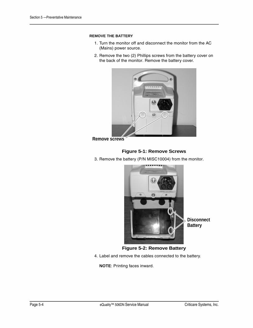
Section 5 —Preventative Maintenance
Page 5-4 eQuality™ 506DN Service Manual Criticare Systems, Inc.
REMOVE THE BATTERY
1. Turn the monitor off and disconnect the monitor from the AC (Mains) power source.
2. Remove the two (2) Phillips screws from the battery cover on the back of the monitor. Remove the battery cover.
Figure 5-1: Remove Screws3. Remove the battery (P/N MISC10004) from the monitor.
Figure 5-2: Remove Battery4. Label and remove the cables connected to the battery.
NOTE: Printing faces inward.
Remove screws
Disconnect Battery

Criticare Systems, Inc. eQuality™ 506DN Service Manual Page 5-5
Section 5 —Preventative Maintenance
REPLACE THE BATTERY
1. Attach the battery cables to the new battery (P/N MISC10004).
IMPORTANT: Connect the red battery cable to the positive battery terminal and the black cable to the negative battery terminal.
Figure 5-3: Connecting the Battery2. Slide battery into the battery bay.
3. Reattach the battery cover with the two (2) screws removed earlier. Torque to 5 in lbs.
Fuse Removal/Replacement
There are two AC power fuses located at the rear of the monitor directly below the AC power entry socket.
• Use 250V time delay fuses (FUSE T TIME LAG .5mA L 250V 5X20; P/N 82013B002).
1. With a flat blade screwdriver, turn the fuse cover(s) out.
2. Gently pull the fuse cover(s) with fuse(s) out of the fuse assembly.
3. Gently pull the fuse(s) out of the fuse cover(s).
4. Reassemble in reverse order.
REDBLK

Section 5 —Preventative Maintenance
Page 5-6 eQuality™ 506DN Service Manual Criticare Systems, Inc.
Annual Testing You may perform the following tests as part of a periodic safety check. The following safety tests are designed so that the monitor’s quality/warranty seal does not need to be broken. If the monitor fails any portion of these tests contact Criticare Support for additional information.
Descriptions of service tests can be found in “Service Testing & Calibration” in Section 6. Some tests may require specialized equipment.
Accessory Testing Check the patient cables monthly for damage, loose wires/connections, loose connectors, cracked housing, etc. Check the cuffs for leakage as part of the NIBP verification.
Functional andSafety Testing
Annual testing should include electrical safety testing, the withstanding voltage, and electrical leakage tests. Additional functional tests and verifications are provided that you may perform as designated by hospital protocols or as necessary.
A complete list of functional and safety tests are included here.
1. Electrical Safety Testsa. Withstanding Voltage (Hi-Pot)b. Electrical Leakage
2. Functional Testsa. System Checkb. Speaker Performance and Alarm Verificationc. Power Supply Performance
3. Vital Sign Modules Verificationsa. NIBPb. Oximeter (SpO2)
Criticare Systems, Inc. eQuality™ 506DN Service Manual Page 5-7
Section 5 —Preventative Maintenance
Equipment and Tools The following procedures assume that the technician has an ESD safe workbench available, a set of electronic hand tools, and a digital multimeter with a 10 amp setting. You need a withstanding voltage tester (Hi-Pot), an oscilloscope, and an electrical leakage tester for safety testing. At the beginning of each test special equipment may be listed. You may also need a variety of customized cables, clips, and test fixtures to complete all the tests.
The following tools are needed for these procedures:• Set of hand tools• Digital multimeter (10A)• Oscilloscope• Power supply• Setra 350-1 (or equivalent) manometer with Tee• Dynatech 232D (or equivalent) leakage tester• Dynatech cufflink NIBP simulator with neonatal and adult cuffs• 7512DT Associated Research withstanding voltage tester
(or equivalent)• Smart Sat SS-100A pulse oximetry analyzer (or equivalent)• Computer with CSI NIBP Service program (P/N 97082A003)
and WFSDLOAD program (P/N 97134A002)• SpO2 Hi-Pot Test Fixture (see “Test Fixtures” in this section)• SpO2 Leakage Test Fixture (see “Test Fixtures” in this section)• Nurse Call Box (see “Test Fixtures” in this section)• Screw in order to Hi-Pot to case• Serial cable with null modem (P/N 87016B002)• AC (Mains) Power cord• 700 cc factory test block• Cat 511SD finger sensor (or equivalent) with optical load (foam
packing peanut)

Section 5 —Preventative Maintenance
Page 5-8 eQuality™ 506DN Service Manual Criticare Systems, Inc.
Test Fixtures SPO2 HI-POT TEST FIXTURE
SPO2 LEAKAGE TEST FIXTURE
NURSE CALL BOX
D1 D2 D3 D4
LED LED LED LED
1 2
CON1
J1
1 2
CON2
J2 +12V Batt. Pos.
+12V Batt. Neg.
J11 pins 1 and 2
J11.4
Alligator clips toconnect to battery 3.5 mm stereo plug

Criticare Systems, Inc. eQuality™ 506DN Service Manual Page 5-9
Section 5 —Preventative Maintenance
HOT/NEUTRAL TO GROUND HI-POT FIXTURE
NURSE CALL HI-POT FIXTURE
Section 5 —Preventative Maintenance
Page 5-10 eQuality™ 506DN Service Manual Criticare Systems, Inc.
Electrical Safety Tests Perform this test whenever the monitor housing is opened before using the monitor on patients.
Withstanding VoltageTest (Hi-Pot)
• High Voltage! The following test procedure requires working with exposed electrical circuits and should only be attempted by experienced technicians.
Equipment Needed This test requires a Kikusui 7512DT Associated Research (or equivalent) Hi-Pot tester. The tester should be rated for 4000 VAC maximum.
Setup Hi-Pot Tester • Hi limit = 1mA
• Lo Limit =0.0uA
• Arc Fail = OFF
• Arc Sense = 5
• Ramp Hi = Off
• Charge Lo = 0.0 uA
• Ramp Time = 1 second
• Dwell Time =1 second
• AC/DC =DC
WARNING ! !

Criticare Systems, Inc. eQuality™ 506DN Service Manual Page 5-11
Section 5 —Preventative Maintenance
Hi-Pot Performance Test NOTE: Do not power up the 506DN monitor during the Hi-Pot steps.
1. Connect the 506DN monitor to the measurement receptacle of the Hi-Pot tester. Test “Hot/Neutral” to “Ground” at 2500VDC.
2. Install a screw into the roll stand-mounting insert located on the rear of the enclosure. Attach the ground test lead of the Hi-Pot tester to the screw and the red test lead to “Hot/Neutral.” Test at 2500VDC.
3. Connect the DOX SpO2 Hi-Pot cable to the ground test lead of the Hi-Pot tester and connect to the SpO2 connector on the monitor. Attach the red test lead to “Hot/Neutral” and test at 4242VDC.
4. Connect the DOX SpO2 Hi-Pot cable to the red lead of the Hi-Pot tester and connect the ground test lead to the Hi-Pot tester to the DB9 shell of the 506DN. Test at 2500VDC.
5. Connect red lead of the Hi-Pot tester to “Hot/Neutral” and the black lead to the Nurse Call cable. Test at 2500VDC.
Leakage Testing This test requires a Dynatech 232D Safety Analyzer (or equivalent) leakage testing device.
Setup Procedure(Self-Test)
Perform a self test, if applicable, to ensure proper operation of the leakage tester. If the self test fails, don’t proceed with this test.
For Dynatech 232D only:
1. Perform a self test on the Dynatech 232D. Set the MODE switch to SELF test. The display should read 1000 (±20) and the CURRENT SOURCE ACTIVE lamp should be on.
• If these conditions are not met do not continue with the leakage test.
2. Set the MODE switch on the Dynatech to L1-L2. The display should read 220 to 240 VAC (or 110 to 130 VAC if supply voltage is 120 VAC). Set the MODE switch to L1-GND. The display should read no more than 5% of the previous line voltage measurement. Set the MODE switch to L2-GND. This reading should be the same as the first reading, ±5 VAC.
CAUTION ! !
Section 5 —Preventative Maintenance
Page 5-12 eQuality™ 506DN Service Manual Criticare Systems, Inc.
Leakage Procedure NOTE: The monitor must be on throughout the leakage test. This test should be performed at a supply voltage of 230VAC. If supply voltage is 120VAC, then acceptable leakage current limits are one-half the value stipulated.
NOTE: If attaching acceptable leakage measurements to the check sheet, check “PASS” on each step completed.
1. Connect the monitor to the measurement receptacle of the leakage tester.
2. Configure the leakage tester to test internal case leakage (Dynatech 232D: MODE = CASE LEAKAGE/GROUND CONDUCTOR). Record measurements on the check sheet for the following:• Normal Polarity (<50uA)(<100uA)• Reverse Polarity (<50uA)(<100uA)• Normal Polarity, Open Ground (<250uA)(<500uA)• Reverse Polarity, Open Ground (<250uA)(<500uA)
3. Configure the leakage tester to test external case leakage (Dynatech 232D: MODE = CASE LEAKAGE/EXT. LEAD). Clip the external leakage test lead to the DB9 shell of the monitor. Record measurements on the check sheet for the following:• Normal Polarity (<50uA)(<100uA)• Reverse Polarity (<50uA)(<100uA)• Normal Polarity, Open Ground (<250uA)(<500uA)• Reverse Polarity, Open Ground (<250uA)(<500uA)

Criticare Systems, Inc. eQuality™ 506DN Service Manual Page 5-13
Section 5 —Preventative Maintenance
4. Connect the SpO2 leakage cable to the LA terminal on leakage tester.
Record the measurement on the check sheet or attach print out of the acceptable test result to the check sheet and test. Configure the leakage tester to measure the patient connection to GND leakage. (Dynatech 232D: MODE = ECG, LEADS = ALL TO GND).• Normal Polarity (<5uA)(<10uA) • Normal Polarity, Open Ground (<25uA)(<50uA)
5. Remove the SpO2 cable
• Hazardous voltage are present on the test leads. Do not touch these leads or the monitor while performing this test.
6. Connect the SpO2 leakage cable to the LA terminal on leakage tester.
Record the measurement on the check sheet or attach print out of the acceptable test result to the check sheet and test. Configure the leakage tester to measure patient isolation. (Dynatech 232D: MODE = ECG, LEADS =ISOLATION TEST) • Normal Polarity (<50uA) Press the isolation button.
WARNING ! !
Section 5 —Preventative Maintenance
Page 5-14 eQuality™ 506DN Service Manual Criticare Systems, Inc.
Functional Tests
System Check Confirm the proper start up of the monitor. No cable should be attached to the external serial port during this test.
1. Press the POWER key to start the monitor. The alarm icon displays and the sensor is detected.
The monitor displays the following messages:
CRITICARE SYSTEMS INC.
506DN SERIES
REVISION x.x (C) 200X
2. Hold the MENU key while you restart the monitor. The reset to defaults message appears. Depending on configuration of the unit, this message may appear as USER DEFAULTS, HOSPITAL DEFAULTS, or ALT. C. DEFAULTS.
3. Press the MENU key and press the UP/DOWN arrow keys to scroll to the CONFIGURATION menu. Press the MENU key to enter the CONFIGURATION menu.
4. Press the UP/DOWN arrow keys to scroll to CONTRAST. Check the LCD CONTRAST setting. Adjust the contrast as necessary.
5. Continue in the CONFIGURATION menu. Ensure the time and date are correct.
Criticare Systems, Inc. eQuality™ 506DN Service Manual Page 5-15
Section 5 —Preventative Maintenance
Speaker Performance,Alarms Verification
To verify alarm circuitry:
1. Set the alarm volume to 10 in the ALARMS menu.
2. With no cuff attached press the NIBP START/STAT/STOP key. The monitor attempts to inflate and responds with a message: BP: CHECK CUFF.
3. Listen for the low level alarm tone. It is a burst of two pulses at the same pitch. The bursts should repeat every 10 seconds.
4. Set the alarm level to 1 and cause another CHECK CUFF alarm. The volume should be decreased but still audible.
5. Set the alarm volume to OFF and cause another CHECK CUFF alarm. No alarm tone should be audible. Confirm that the alarm bell indicator appears.
6. Return the alarm volume setting to 4.
7. In the CONFIGURATION menu, turn on the temperature module and turn off the NIBP monitoring module. The NIBP numerics should not display on the LCD main screen.
8. Restart the monitor to reset the NIBP module to ON.
Power Supply Performance 1. Verify the green AC LED lights up the AC power symbol on the front membrane when the monitor is plugged into the AC inlet.
2. Verify the monitor powers up on AC only.
3. Verify the monitor powers up on DC only with a battery.

Section 5 —Preventative Maintenance
Page 5-16 eQuality™ 506DN Service Manual Criticare Systems, Inc.
Monitoring Module Verification
NIBP Verification The NIBP verification requires Dynatech Nevada NIBP Analyzer. Connect the 506DN monitor to a Dynatech Nevada NIBP Analyzer set for the following operation.
NIBP Analyzer SettingsAdult 120/80 (90); Heart Rate 120 bpmPressure Adjustments: Gain 100%; Shift 4
Use a tee connection with an adult dummy cuff. Connect to the 0-300 mmHg port of the NIBP analyzer. A neonatal dummy cuff is also required for complete testing.
It is recommended that the actual cuffs (to be used with the monitor) are setup as dummy cuffs for this verification. Wrap the cuff snug with bubblewrap around a sturdy cylinder.
1. Connect the monitor to an AC power source and turn on the monitor. Set the monitor to the ADULT Mode (Adult Patient).
2. Press the NIBP START/STAT/STOP key and allow the monitor to take at least four (4) readings. The systolic, diastolic and mean readings should not vary by more than ±4% or ±4mmHg (whichever is greater) from the calculated average. Each reading shall not vary more than 8 mmHg from the simulator setting.
Leave the monitor connected to the NIBP analyzer. Change the NIBP analyzer setting to the neonate configuration with a simulator setting of 80/50 (62) mmHg; Heart Rate 80 bpm. A neonatal dummy cuff must be used during this test.
1. Set the monitor to NEONATE Mode in the Main Menu.
2. Press the NIBP START/STAT/STOP key and allow the monitor to take at least four (4) readings. The systolic, diastolic and mean readings should not vary by more than ±4% or ±4mmHg (whichever is greater) from the calculated average. Each reading shall not vary more than 8 mmHg from the simulator setting.
3. If the monitor continues to fail verification contact the Criticare Technical Support Department.
Criticare Systems, Inc. eQuality™ 506DN Service Manual Page 5-17
Section 5 —Preventative Maintenance
NIBP Seal Test EQUIPMENT REQUIRED
• Digital manometer, calibrated (accuracy of ±0.05%)
• Manual squeeze bulb with valve
• “Tee” connector
SETUP
1. Connect the manual squeeze bulb to the “tee” connector.
2. Connect the digital manometer to the “tee” connector.
3. Connect the “tee” connector to the NIBP connector on the monitor.
PROCEDUREThe 506DN monitor has a simple test mode for checking the seal and pressure transducer. The instructions are as follows:
1. Press the POWER key while holding the DOWN arrow key.
2. The monitor begins its normal boot sequence but enters the Service Mode instead. The LCD shows the message SERVICE DISPLAY.
3. Press the DOWN arrow to scroll through the menu options to TEST MENU.
4. Press the DOWN arrow to scroll through the test menu options to NIBP SEAL <-- OFF.
5. Press the MENU key. The display should read NIBP SEAL --> OFF.
6. Press the DOWN arrow once to turn the test to ON.
7. Press the MENU key to start the test.
The monitor will then function as a plain pressure meter allowing the technician to manual test the pressure transducer with a manometer.
Pump up the manual squeeze bulb. Verify that the manometer readings agree with the monitor readings. The accuracy of the pressure transducer for static pressure measurements should be within ±2 mmHg or ±2% of reading, whichever is greater. The current pressure will be displayed in the LCD window.

Section 5 —Preventative Maintenance
Page 5-18 eQuality™ 506DN Service Manual Criticare Systems, Inc.
SpO2 Verification 1. Using a SpO2 finger sensor, verify heart rate and plethysmograph operation displayed on the LED’s within 15 seconds. Verify no SpO2 error messages appear (alarm violations may occur depending on individual readings and monitor set-up).
2. Remove your finger from the sensor and verify SPO2: SENSOR message is displayed when the finger sensor is plugged in, but with no finger inserted in the sensor.
3. Verify SPO2: HIGH AMBIENT message appears by introducing a higher than normal amount of ambient light on the SpO2 sensor detector.
4. Disconnect the DOX SpO2 sensor from the unit after power up.
5. Verify a SPO2:NO SENSOR displays on the LCD.

Criticare Systems, Inc. eQuality™ 506DN Service Manual Page 5-19
Section 5 —Preventative Maintenance
Functional and Safety Testing Checklist
Use the checklist on the following pages to record the successful completion of the annual safety tests and verification.
Functional and Safety Testing Checklist (Page 1 of 2)Copy this checklist as needed to record results.
Model __________________________________Unit serial number___________________________ Software Rev. ____________Tested by __________________________________ Date _____________________
Electrical Safety TestsHi-Pot Tests PASS FAIL
Hi-Pot Hot/Neutral to Ground @ 2500VDC _____ _____Hi-Pot Hot/Neutral to Metal Case @ 2500VDC _____ _____Hi-Pot Hot/Neutral to DOX SpO2 Gnd @ 4242VDC _____ _____Hi-Pot DOX SpO2 to DB-9 shell @ 2500VDC _____ _____Hi-Pot/Neutral to Nurse Call @ 2500VDC _____ _____
Leakage Tests PASS FAILPerform Self Test on Leakage Tester _____ _____Leakage GND CONDUCTOR Normal Polarity (<50/<100uA) _____uA _____uALeakage GND CONDUCTOR Normal Reverse (<50/<100uA) _____uA _____uALeakage Open GND and Normal Polarity (<250/<500uA) _____uA _____uALeakage Open GND and Reverse Polarity (<250/<500uA) _____uA _____uALeakage Case Normal Polarity (<50/<100uA) _____uA _____uALeakage Case Reverse Polarity (<50/<100uA) _____uA _____uALeakage Case Normal Polarity Open Ground (<250/<500uA) _____uA _____uALeakage Case Reverse Polarity Open Ground (<250/<500uA) _____uA _____uADOX SpO2 LEAKAGE Normal Polarity (<5/<10uA) _____uA _____uADOX SpO2 LEAKAGE Normal Polarity Open GND (<25/<50uA) _____uA _____uAIsolation test DOX SpO2 (<25/<50uA) _____uA _____uA

Section 5 —Preventative Maintenance
Page 5-20 eQuality™ 506DN Service Manual Criticare Systems, Inc.
Functional and Safety Testing Checklist (Page 2 of 2)PASS FAIL
Functional TestsAlarm Functions
Verify Pulse volume operation from 0 to 10 _____ _____Verify Alarm volume operation from 0 to 10 _____ _____Verify 2 minute Alarm Silence function _____ _____Verify permanent Alarm Silence function _____ _____Verify Nurse Call lights up when alarm is triggered _____ _____
Display FunctionsVerify Green Charge LED w/AC power connected _____ _____
Powerup FunctionVerify unit powers up with AC plug in _____ _____Verify unit powers up on battery _____ _____
NIBP FunctionSimulator set to Adult mode @120/80 – 1 min cycle(Each reading does not vary by more than ±4% or ±4mmHg (whichever is greater) from the calculated average.)_____/____, _____/____, _____/____, _____/____Average: _____/____ _____ _____Simulator set to Neonate mode @80/50 – Stat mode(Each reading does not vary by more than ±4% or ±4mmHg (whichever is greater) from the calculated average.)_____/____, _____/____, _____/____, _____/____Average: _____/____ _____ _____Seal Test _____ _____
SpO2 FunctionsVerify SPO2: NO SENSOR condition _____ _____Verify SPO2: SENSOR condition _____ _____Verify SPO2: HIGH AMBIENT condition _____ _____Take SPO2 & HR readings _____ _____Verify LED Bargraph _____ _____Sensor symbol operation _____ _____Verify SPO2: LOST condition _____ _____
CERTIFICATION THAT THE UNIT IS CALIBRATED AND FUNCTIONING PROPERLYNAME
COMMENTS

Criticare Systems, Inc. eQuality™ 506DN Service Manual Page 6-1
Section 6 —Service Testing & Calibration
Monitor Testing If the monitor fails any portion of these tests contact the Criticare Service Department for additional information. See “Functional and Safety Testing” in Section 5 for functional and electrical safety tests. Monitoring module verifications are also located in “Service Checks” in Section 5.
Service Checks If the monitor shows any signs of physical damage return it to Criticare for repair.
• If the unit fails any tests, contact Criticare. Do not use the monitor for patient monitoring until you fix the problem.
• No user-serviceable parts exist inside the monitor. Do not remove the cover. Refer all servicing to a qualified technician.
Field Service Testing
• Service testing procedures require working with exposed electrical circuits and only experienced electrical or biomedical technicians should attempt these procedures.
• Any time a monitor is altered through repair or hardware adjustment, you should fully test it before use.
• Always follow ESD precautions when you perform any of the procedures discussed in this section.
• The manufacturer recommends that a serviced monitor be allowed to run for 24 hours before you place the monitor back into operation.
• Modules and PCBs that you have repaired may require more extensive testing than what is described in this manual.
The following tests are designated for monitors that require service repairs. Opening the monitor may void your warranty, so it is important to contact Criticare customer service before you attempt any repair.
The pre-assembly testing of printed circuit boards (PCBs) is not covered in this manual. Disassembly of surface mounted components on PCBs in not recommended. Tests provided here are only for the identification of damaged or degraded PCBs.
WARNING ! !
WARNING ! !
CAUTION ! !
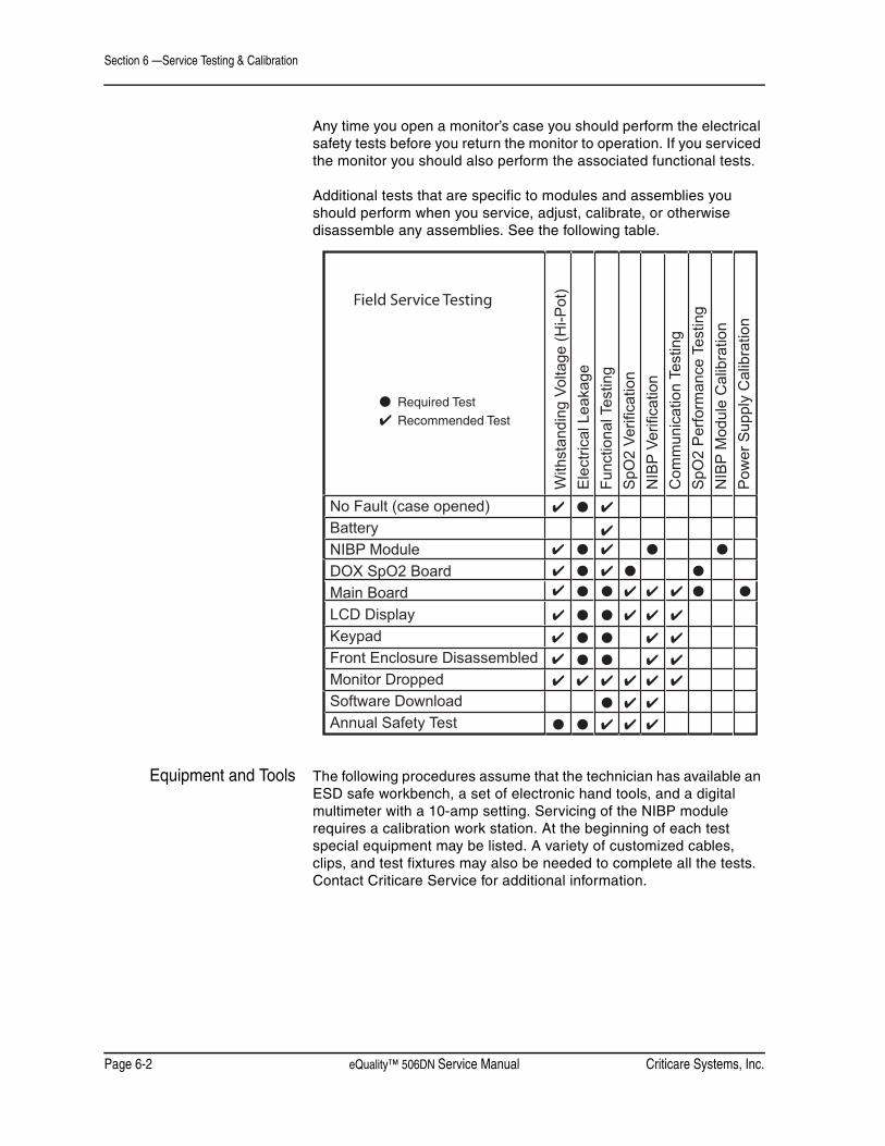
Section 6 —Service Testing & Calibration
Page 6-2 eQuality™ 506DN Service Manual Criticare Systems, Inc.
Any time you open a monitor’s case you should perform the electrical safety tests before you return the monitor to operation. If you serviced the monitor you should also perform the associated functional tests.
Additional tests that are specific to modules and assemblies you should perform when you service, adjust, calibrate, or otherwise disassemble any assemblies. See the following table.
Equipment and Tools The following procedures assume that the technician has available an ESD safe workbench, a set of electronic hand tools, and a digital multimeter with a 10-amp setting. Servicing of the NIBP module requires a calibration work station. At the beginning of each test special equipment may be listed. A variety of customized cables, clips, and test fixtures may also be needed to complete all the tests. Contact Criticare Service for additional information.
No Fault (case opened) Battery NIBP Module DOX SpO2 Board Main Board LCD Display Keypad Front Enclosure Disassembled Monitor Dropped Software Download Annual Safety Test
With
stan
ding
Vol
tage
(Hi-P
ot)
Ele
ctric
al L
eaka
ge
Func
tiona
l Tes
ting
SpO
2 Ve
rific
atio
n N
IBP
Verif
icat
ion
Com
mun
icat
ion
Test
ing
SpO
2 P
erfo
rman
ce T
estin
g N
IBP
Mod
ule
Cal
ibra
tion
Pow
er S
uppl
y C
alib
ratio
n
Required Test
Recommended Test
Field Service Testing
●
✔
✔ ● ✔
✔
✔ ✔ ● ● ●
✔ ✔ ●
✔
●
●
●
●
● ●
✔ ✔ ✔ ✔ ✔
✔ ✔ ✔
✔ ✔ ✔
✔ ✔ ●
●
●
●
●
● ●
● ●
✔ ✔
✔ ✔
✔ ✔ ✔
✔
✔
✔
✔

Criticare Systems, Inc. eQuality™ 506DN Service Manual Page 6-3
Section 6 —Service Testing & Calibration
Communication Testing
Equipment Required • Windows-compatible computer with DB-9 serial port
NOTE: If your computer uses USB ports instead of a serial port a USB/Serial converter with software is needed to complete this procedure. Install the converter and software on the computer as directed by the converter manufacturer. The following adapters are recommended.• IOmega USB to Serial/PDA Converter Cable .....GUC232A• Keyspan USB Serial Adapter ............................USA-19HS
• Serial download cable (pn 87016B002)
• A common computer terminal program
Pinout Chart
Figure 6-1: Pinout Chart
Procedure 1. Set PRINT TO to SERIAL in the COMMUNICATION menu.
2. Set SERIAL to TEXT.
3. Connect the COM port to the serial port on the computer or the USB port (with adapter) on the laptop.
4. Start Hyper Terminal from the Accessories|Communication menu on the PC. Settings: 19200 bps, 8-N-1, or Auto Detect.
Figure 6-2: PC HyperTerminal5. Press the SEND key on the monitor to initiate a print of data.
6. Ensure data prints to the computer.
5 4 3 29 8 7 6
1
Pinout ChartPIN SIGNAL1 CD (Carrier Detect)2 RX3 TX4 DTR5 Ground6 DSR7 RTS8 CTS9 RI (Not Used)
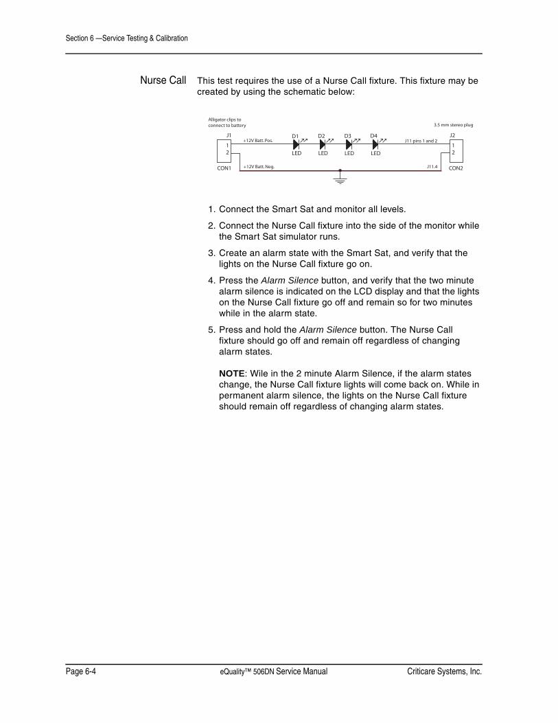
Section 6 —Service Testing & Calibration
Page 6-4 eQuality™ 506DN Service Manual Criticare Systems, Inc.
Nurse Call This test requires the use of a Nurse Call fixture. This fixture may be created by using the schematic below:
1. Connect the Smart Sat and monitor all levels.
2. Connect the Nurse Call fixture into the side of the monitor while the Smart Sat simulator runs.
3. Create an alarm state with the Smart Sat, and verify that the lights on the Nurse Call fixture go on.
4. Press the Alarm Silence button, and verify that the two minute alarm silence is indicated on the LCD display and that the lights on the Nurse Call fixture go off and remain so for two minutes while in the alarm state.
5. Press and hold the Alarm Silence button. The Nurse Call fixture should go off and remain off regardless of changing alarm states.
NOTE: Wile in the 2 minute Alarm Silence, if the alarm states change, the Nurse Call fixture lights will come back on. While in permanent alarm silence, the lights on the Nurse Call fixture should remain off regardless of changing alarm states.
D1 D2 D3 D4
LED LED LED LED
1 2
CON1
J1
1 2
CON2
J2 +12V Batt. Pos.
+12V Batt. Neg.
J11 pins 1 and 2
J11.4
Alligator clips toconnect to battery 3.5 mm stereo plug

Criticare Systems, Inc. eQuality™ 506DN Service Manual Page 6-5
Section 6 —Service Testing & Calibration
DOX SpO2 Performance Testing
This test requires a SmartSat Pulse Oximetry Analyzer, Model SS-100A. The SmartSat is a programmable simulator and probe analyzer. The SmartSat is the recommended device for testing the DOX SpO2 module. The SmartSat, model SS-100A, is available from Clinical Dynamics Corp. of Wallingford, CT.
The SmartSat comes standard with a Lemo style connection. The Cat. No. 913A adapter that converts Lemo to DB-9 style SpO2 connections is needed for the 506N3 Series monitor. The analyzer also has a custom port designed for testing DOX™ SpO2 sensors.
Programming theSmartSat Analyzer
The SmartSat can be used for spot checking SpO2 values using the manual settings. The manufacturer recommends using a timed and programmed sequence to ensure that there is optimal performance.
Auto Seq: Model 506DN Oximeter DOXLevel SPO2 Limits Heart rate Limits
Test Procedure 1. Verify the SpO2 module as described in “SpO2 Verification” in Section 5.
2. Attach the monitor to the SmartSat.
3. Start the SmartSat programmed sequence: SmartSat Auto Sequence. Verify that the monitor’s reported SpO2 values are within the limits specified.Level Saturation Limits Heart Rate Limits
(%) (%) (bpm) (bpm)1 98 97 - 99 40 39-412 96 94 – 98 60 59-613 90 88 – 92 80 79-814 78 76 – 80 100 99-1015 61 58 – 64 120 119-1216 52 49 – 55 180 179-1817 40 37 – 43 300 297-303
4. Even if the monitor fails only one level, rerun the sequence after 30 seconds. Only if the monitor is successful the second time, do you pass the monitor.
5. If the monitor fails again, contact the CSI Service Department.

Section 6 —Service Testing & Calibration
Page 6-6 eQuality™ 506DN Service Manual Criticare Systems, Inc.
NIBP Calibration The manufacturer recommends that NIBP calibration be performed only at authorized service facilities. The NIBP calibration procedures require specialized equipment (Cat. No. 454-G Calibration Kit) necessary for proper calibration testing.
Equipment Required • Windows-compatible computer with DB-9 serial port
• USB ports: a USB/Serial converter with software is needed to complete this procedure. Install the converter and software on the computer as directed by the converter manufacturer.
• Digital manometer, calibrated (accuracy of ±0.05%)
• ESD Protected Work Bench
• Calibration Kit (Cat. No. 454-G), includes:
• Serial null modem cable DB9F-DB9F 6-foot null modem cable (pn 87016B002)
• Calibration fixture with 700cc reservoir and tee connector
• Service program software CD-ROM (pn 97082A003, revision 2 or higher)
Installing the PCService Program
The NIBP Service Program is provided on a self-installing CD-ROM disk. If the CD-ROM does not run automatically you may need to click on the CD-ROM drive icon.
Run the auto-installation disk. The program NIBPSvc.exe will be loaded into the Program Files directory. The new folders CSI\Tools will be created. A launch icon will also be placed on the desktop of the computer.
Configuring the Ports The Service Program is designed to operate using a serial COM1, COM3 or COM4 port. If your computer uses USB ports instead of a serial port an adapter will be required. The following adapters are recommended.
• IOmega USB to Serial/PDA Converter Cable .........GUC232A
• Keyspan USB Serial Adapter.................................USA-19HS
If COM1, COM3 or COM4 is not available as a free port, the ports will need to be reconfigured in the computer’s device manager. Go to Control Panel\System\Hardware and select Device Manager. Select Ports and reassign the alternate port or the USB to Serial Adapter to COM1, COM3 or COM4. For laptops using a USB adapter, select COM 4 or an alternate COM port as necessary.
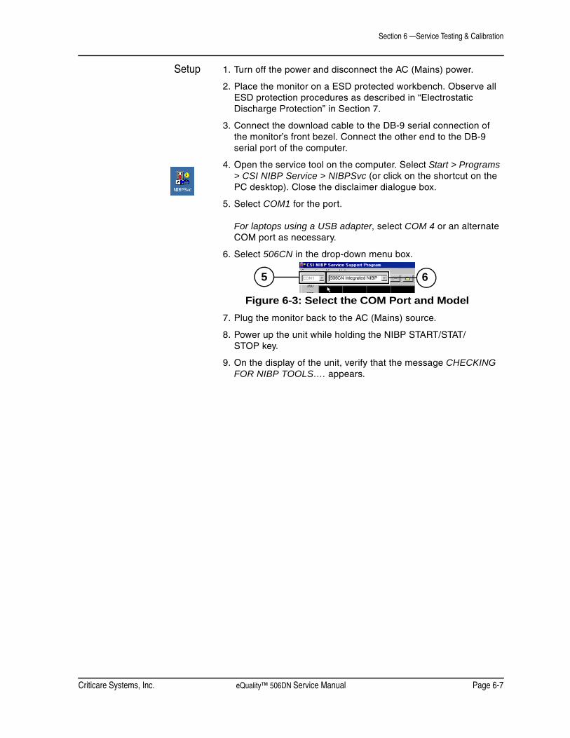
Criticare Systems, Inc. eQuality™ 506DN Service Manual Page 6-7
Section 6 —Service Testing & Calibration
Setup 1. Turn off the power and disconnect the AC (Mains) power.
2. Place the monitor on a ESD protected workbench. Observe all ESD protection procedures as described in “Electrostatic Discharge Protection” in Section 7.
3. Connect the download cable to the DB-9 serial connection of the monitor’s front bezel. Connect the other end to the DB-9 serial port of the computer.
4. Open the service tool on the computer. Select Start > Programs > CSI NIBP Service > NIBPSvc (or click on the shortcut on the PC desktop). Close the disclaimer dialogue box.
5. Select COM1 for the port.
For laptops using a USB adapter, select COM 4 or an alternate COM port as necessary.
6. Select 506CN in the drop-down menu box.
Figure 6-3: Select the COM Port and Model7. Plug the monitor back to the AC (Mains) source.
8. Power up the unit while holding the NIBP START/STAT/STOP key.
9. On the display of the unit, verify that the message CHECKING FOR NIBP TOOLS…. appears.
5 6
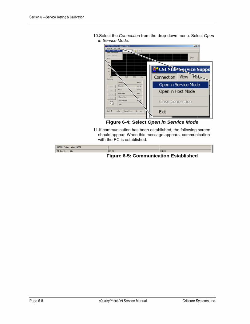
Section 6 —Service Testing & Calibration
Page 6-8 eQuality™ 506DN Service Manual Criticare Systems, Inc.
10.Select the Connection from the drop-down menu. Select Open in Service Mode.
Figure 6-4: Select Open in Service Mode11.If communication has been established, the following screen
should appear. When this message appears, communication with the PC is established.
Figure 6-5: Communication Established

Criticare Systems, Inc. eQuality™ 506DN Service Manual Page 6-9
Section 6 —Service Testing & Calibration
Calibrate 1. Select Calibrate from the service tool screen on the PC.
Figure 6-6: Select Calibrate2. A box appears as shown. Verify that the pressure at the cuff is
“0mmHg” ±2mmHg.
Figure 6-7: Verify Cuff Pressure

Section 6 —Service Testing & Calibration
Page 6-10 eQuality™ 506DN Service Manual Criticare Systems, Inc.
3. Click Next and verify that the pressure at the cuff is “0 mmHg” ±2 mmHg.
Figure 6-8: Verify Cuff Pressure4. Connect a manometer to power. Connect the open tube to the
fitting on the back of the manometer. Connect a 700cc block into on of the tubes.
Connect the fitting from the manometer onto the NIBP fitting on the unit. Click Next again. The pump should inflate to 250 mmHg and then settle. Use the UP or DOWN buttons to adjust the gain to match the manometer pressure with the cuff pressure.
5. When Manometer and cuff match, select Finish.
Figure 6-9: Finish Calibration6. The cal information will be downloaded into the E2 and
“Calibration Complete” should appear.
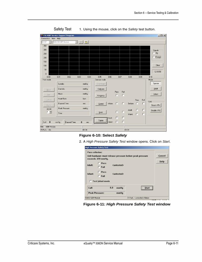
Criticare Systems, Inc. eQuality™ 506DN Service Manual Page 6-11
Section 6 —Service Testing & Calibration
Safety Test 1. Using the mouse, click on the Safety test button.
Figure 6-10: Select Safety2. A High Pressure Safety Test window opens. Click on Start.
Figure 6-11: High Pressure Safety Test window

Section 6 —Service Testing & Calibration
Page 6-12 eQuality™ 506DN Service Manual Criticare Systems, Inc.
3. The cuff pressure should increase until approximately 300-315 mmHg. Verify that the Pass box for Adult contains a checkmark.
Figure 6-12: Adult Test Pass4. Click on the Test Infant Mode. A checkmark should appear in
the box before it. Click Start.
Figure 6-13: Test Infant Mode
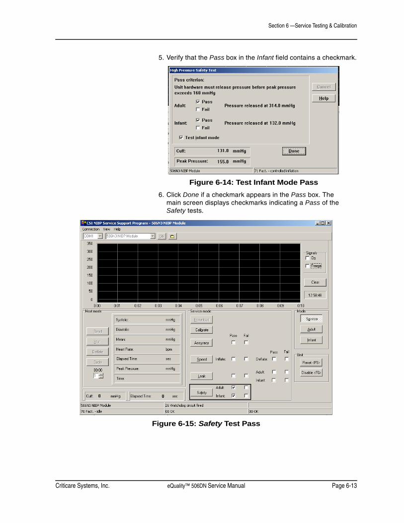
Criticare Systems, Inc. eQuality™ 506DN Service Manual Page 6-13
Section 6 —Service Testing & Calibration
5. Verify that the Pass box in the Infant field contains a checkmark.
Figure 6-14: Test Infant Mode Pass6. Click Done if a checkmark appears in the Pass box. The
main screen displays checkmarks indicating a Pass of the Safety tests.
Figure 6-15: Safety Test Pass

Section 6 —Service Testing & Calibration
Page 6-14 eQuality™ 506DN Service Manual Criticare Systems, Inc.
Speed Test 1. Click on Speed.
Figure 6-16: Select Speed2. A Factory Speed Test window opens. Click on Start.
Figure 6-17: Factory Speed Test Window

Criticare Systems, Inc. eQuality™ 506DN Service Manual Page 6-15
Section 6 —Service Testing & Calibration
3. Verify that the Inflation and Deflation indicates a Pass with checkmarks in the boxes.
Figure 6-18: Factory Speed Test Pass4. If each Pass box has a checkmark, click on the Done button.
5. The main screen displays checkmarks indicating a Pass of the Speed tests.
Figure 6-19: Speed Test Pass

Section 6 —Service Testing & Calibration
Page 6-16 eQuality™ 506DN Service Manual Criticare Systems, Inc.
Leak Test 1. Click on the Leak test button.
Figure 6-20: Select Leak2. A Leak and High Time Test window appears. Click Start.
Figure 6-21: Leak and High Time Test Window
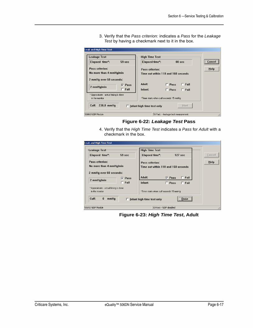
Criticare Systems, Inc. eQuality™ 506DN Service Manual Page 6-17
Section 6 —Service Testing & Calibration
3. Verify that the Pass criterion: indicates a Pass for the Leakage Test by having a checkmark next to it in the box.
Figure 6-22: Leakage Test Pass4. Verify that the High Time Test indicates a Pass for Adult with a
checkmark in the box.
Figure 6-23: High Time Test, Adult
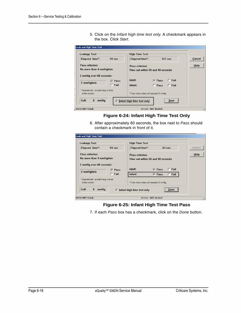
Section 6 —Service Testing & Calibration
Page 6-18 eQuality™ 506DN Service Manual Criticare Systems, Inc.
5. Click on the Infant high time test only. A checkmark appears in the box. Click Start.
Figure 6-24: Infant High Time Test Only6. After approximately 60 seconds, the box next to Pass should
contain a checkmark in front of it.
Figure 6-25: Infant High Time Test Pass7. If each Pass box has a checkmark, click on the Done button.
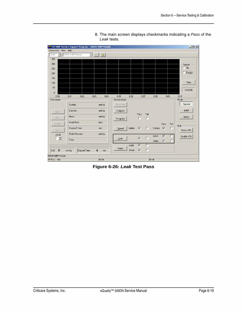
Criticare Systems, Inc. eQuality™ 506DN Service Manual Page 6-19
Section 6 —Service Testing & Calibration
8. The main screen displays checkmarks indicating a Pass of the Leak tests.
Figure 6-26: Leak Test Pass
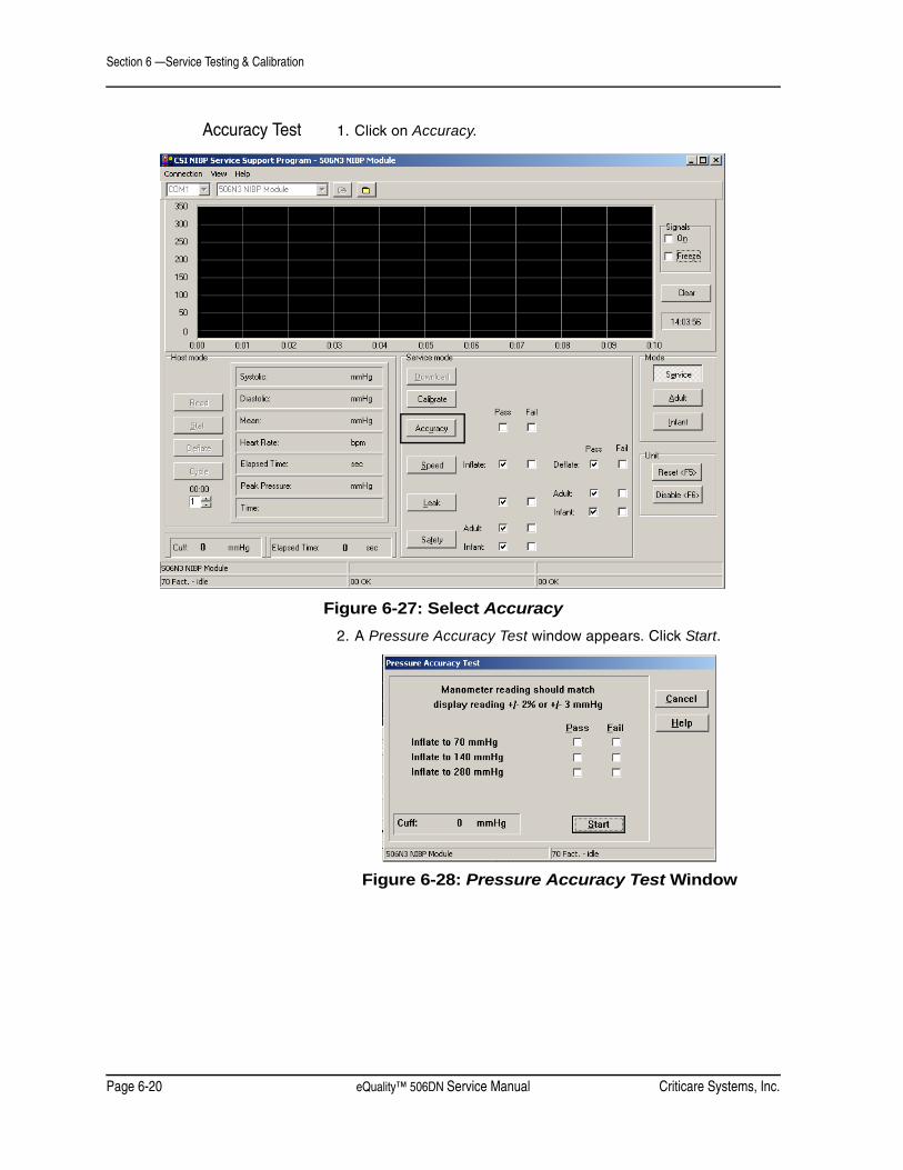
Section 6 —Service Testing & Calibration
Page 6-20 eQuality™ 506DN Service Manual Criticare Systems, Inc.
Accuracy Test 1. Click on Accuracy.
Figure 6-27: Select Accuracy2. A Pressure Accuracy Test window appears. Click Start.
Figure 6-28: Pressure Accuracy Test Window

Criticare Systems, Inc. eQuality™ 506DN Service Manual Page 6-21
Section 6 —Service Testing & Calibration
3. Check the manometer and the cuff pressure. Pressure will inflate to 70 mmHg. Verify that the pressure is within ±2% or ±3 mmHg. If OK click on the Pass box to place a checkmark in the box. Click Next.
Figure 6-29: Pressure Accuracy Test, 70 mmHg4. Repeat for 140 and 280 mmHG.
Figure 6-30: Pressure Accuracy Test, 140 mmHg
Figure 6-31: Pressure Accuracy Test, 280 mmHg5. Click Done if the test passes after the 280 mmHg test.
6. Turn off power and remove serial cable and manometer fixture.


Criticare Systems, Inc. eQuality™ 506DN Service Manual Page 7-1
Section 7 — Disassembly
Before You Begin Opening a monitor and breaking the quality seal can void the manufacturer warranty! Contact the Criticare Service Department before breaking the seal on any monitor.
The following procedures are intended to be used by qualified biomedical engineering or field service personnel for replacement of PCB assemblies. These procedures are not intended to be used for component-level troubleshooting and repair of the PCB assemblies.
The repair procedures for the 506DN monitor are included here for the determination of damaged or unusable assemblies. The manufacturer does not recommend attempting field repair of the printed circuit boards.
See the 506DN Final Assembly drawing in Section 9.
Service Safety
• The following procedures require working with exposed electrical circuits. Repair should only be attempted by experienced electronics technicians.
• Do not short circuit the battery terminals! The resulting high current discharge can cause burns.
• Remove the battery before disassembly to avoid electrical shock.
• Electronic components are selected for specific performance characteristics. Use of substitute replacement parts y cause inaccurate performance or damage the monitor. Order replacement components by their catalog or part number from an authorized dealer.
• Any time an electrical circuit board is altered through repair or adjustment, it must be fully tested before use.
• Replacement of surface mount components is beyond the scope of this manual. Attempting to remove surface mount components with a soldering iron can result in the overheating of the board and damage to tracings. Damaged laminated circuit boards cannot be repaired and require replacement.
• Any electronic repair should be done in compliance with ANSI/IPC-A-610 manufacturing standards for medical equipment. Failure to use standard ANSI/IPC assembly practices can result in permanent damage to the monitor.
WARNING ! !
CAUTION ! !

Section 7 —Disassembly
Page 7-2 eQuality™ 506DN Service Manual Criticare Systems, Inc.
Electrostatic DischargeProtection
The procedures in this section require the handling of electrostatic sensitive components. Microprocessors and other electronic components can be permanently damaged by attempting repairs at an unprotected workstation.
Use all electrostatic discharge (ESD) precautions as described below!
1. Perform the disassembly procedures on an antistatic mat that is grounded. Check the ground cable to insure that it is connected to a good earth ground.
2. Always use a grounded soldering iron.
3. Wear a wrist-grounding strap.
4. The wrist strap and mat should both be connected through a resistor (1 mega-ohm typical) to the same ground source.
5. Wrist-ground straps should be tested on a daily basis.
6. Components should be temporarily stored in metal or antistatic containers. Never store components in plastic dishes.
7. Circuit boards should be stored in sealed antistatic bags or covered antistatic boxes. Never store electronic boards directly in cardboard boxes.
Tools Needed The following is a list of tools needed for disassembly and reassembly of the eQuality 506DN monitor.
• Set of hand tools
• Up to 7 in. torque screwdriver with accessories
• #10 socket
• 5/16 in. nutdriver
• 1/4 in. nutdriver
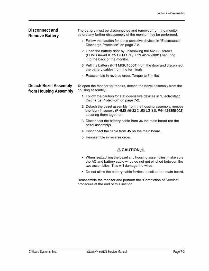
Criticare Systems, Inc. eQuality™ 506DN Service Manual Page 7-3
Section 7 —Disassembly
Disconnect and Remove Battery
The battery must be disconnected and removed from the monitor before any further disassembly of the monitor may be performed.
1. Follow the caution for static-sensitive devices in “Electrostatic Discharge Protection” on page 7-2.
2. Open the battery door by unscrewing the two (2) screws (PHMS #4-40 X .25 GEM Gray; P/N 42745B001) securing it to the back of the monitor.
3. Pull the battery (P/N MISC10004) from the door and disconnect the battery cables from the terminals.
4. Reassemble in reverse order. Torque to 5 in lbs.
Detach Bezel Assembly from Housing Assembly
To open the monitor for repairs, detach the bezel assembly from the housing assembly.
1. Follow the caution for static-sensitive devices in “Electrostatic Discharge Protection” on page 7-2.
2. Detach the bezel assembly from the housing assembly, remove the four (4) screws (PHMS #6-32 X .50 LG SS; P/N 42435B002) securing them together.
3. Disconnect the battery cable from J6 the main board (on the bezel assembly).
4. Disconnect the cable from J5 on the main board.
5. Reassemble in reverse order.
• When reattaching the bezel and housing assemblies, make sure the AC and battery cable wires do not get pinched between the two assemblies. This will damage the wires.
• Do not allow the battery cable ferrites to coil on the main board.
Reassemble the monitor and perform the “Completion of Service” procedure at the end of this section.
CAUTION ! !

Section 7 —Disassembly
Page 7-4 eQuality™ 506DN Service Manual Criticare Systems, Inc.
Bezel Disassembly
Replace Speaker 1. Follow the caution for static-sensitive devices in “Electrostatic Discharge Protection” on page 7-2.
2. Detach bezel assembly from housing assembly (See “Detach Bezel Assembly from Housing Assembly” on page 7-3).
3. On the bezel assembly, disconnect the speaker cable J4 from on the main board.
4. Remove the speaker from the rail on the bezel.
5. Slide the new speaker (P/N 90929A001) under the NIBP assembly and into the rail of the bezel.
Figure 7-1: Reinsert Speaker6. Connect the speaker cable to the main board at J4.
Reassemble the monitor and perform the “Completion of Service” procedure at the end of this section.
Rail

Criticare Systems, Inc. eQuality™ 506DN Service Manual Page 7-5
Section 7 —Disassembly
Replace LCD Display 1. Follow the caution for static-sensitive devices in “Electrostatic Discharge Protection” on page 7-2.
2. Detach bezel assembly from housing assembly (See “Detach Bezel Assembly from Housing Assembly” on page 7-3).
3. Detach the PCB/NIBP assembly from the bezel by removing the two(2) screws (PHMS SEMS #4-40 X .25 LG; P/N 40995B004).
4. Disconnect all of the tubing and remove the connector from P3.
5. On the bezel assembly, disconnect the speaker cable from J4 on the main board.
6. Remove speaker from the rail on the bezel.
7. Remove the two (2) screws (PHMS 4-40 X .312 SEMS; P/N 40995B011) that secure the DOX SpO2 board.
8. Remove the two (2) plastic screws that secure the DOX PCB.
9. Lift and remove the DOX board and insulator.
10.Remove the four (4) screws (PHMS 4-40 X .25 SEMS;P/N 40995B005) that secure the main board.
11.Disconnect the LCD display’s ribbon cable from J1 on the main board.
12.Unlock the membrane tail from J2 on the main board.
13.Lift and remove the main board.
14.Detach LCD display and display shield from the bezel by removing the four (4) screws (PHMS SEMS #4-40 X .25 LG; P/N 40995B005).
15.Lift the display shield (P/N 83401B002) from the bezel.
16.Remove and replace the LCD display (81521B001).
17.Reassemble in reverse order. See assembly drawings for torque instructions.
Perform the “Completion of Service” procedure at the end of this section.
Section 7 —Disassembly
Page 7-6 eQuality™ 506DN Service Manual Criticare Systems, Inc.
Replace Membrane 1. Follow the caution for static-sensitive devices in “Electrostatic Discharge Protection” on page 7-2.
2. Detach bezel assembly from housing assembly (See “Detach Bezel Assembly from Housing Assembly” on page 7-3).
3. Unlock the membrane tail from the connector at J2 on the main board.
4. Remove the old membrane from the bezel.
5. Once removed, clean the bezel with alcohol to remove any residue from the bezel surface.
6. Obtain a new membrane (P/N 45214B001).
7. Slide the membrane tail through the bezel and remove the paper backing from the membrane.
8. Place the membrane flush with the bezel and press firmly around the bezel to ensure that the membrane is flat and no air bubbles are apparent.
9. Reassemble in reverse order.
Perform the “Completion of Service” procedure at the end of this section.

Criticare Systems, Inc. eQuality™ 506DN Service Manual Page 7-7
Section 7 —Disassembly
Replace Main Board 1. Follow the caution for static-sensitive devices in “Electrostatic Discharge Protection” on page 7-2.
2. Detach bezel assembly from housing assembly (See “Detach Bezel Assembly from Housing Assembly” on page 7-3).
3. Detach the NIBP module from the main board by removing the two (2) screws (PHMS SEMS #4-40 X .44 LG; P/N 40995B009) located in the lower middle of the main board.
4. Disconnect the NIBP module from the NIBP fitting (P/N 42014B001) on the side panel (P/N 45225B001).
5. Disconnect the NIBP module’s ribbon cable from P3 on the main board.
6. Disconnect the NIBP module’s open tube from the SENS1 connector on the main board.
7. Remove SpO2 board by removing the four (4) screws.
NOTE: Two different types of screws are used to attach the SpO2 board to the insulator board. The two (2) screws (PHMS #4-40 X .25 LG, NYLON; P/N 42744B001) on the left side of the board differ from the two (2) screws (PHMS SEMS #4-40 X .44 LG; P/N 40995B011) on the right side of the board.
8. Detach the insulator board (P/N 42740B001) by breaking the solder point between the insulator and main boards. (See 506DN assembly drawing in Section 9.)
9. Detach the PCB/NIBP assembly from the bezel by removing the four (4) screws (PHMS SEMS #4-40 X .25 LG; P/N 40995B005).
10.Unlock the membrane tail from the connector at J2 on the main board.
11.Disconnect the LCD display’s ribbon cable from J1 on the main board.
12.Remove main board from bezel.
13.On the bezel assembly, disconnect the speaker cable from J4 on the main board.
14.Remove the speaker from the rail on the bezel.
15.Remove the two (2) standoffs (STANDOFF M/F #4-40 X .375 LG, NYLON; P/N 42742B001) and two (2) hex nuts (HEX NUT #4-40, NYLON; P/N 42743B001) from the old main board.

Section 7 —Disassembly
Page 7-8 eQuality™ 506DN Service Manual Criticare Systems, Inc.
16.Obtain a new main board (P/N 91410A001).
17.Reassemble in reverse order. Refer to 506DN assembly drawing in Section 9 for solder point when connecting the main and insulator boards.
NOTE: When reassembling, after the NIBP module and SpO2 board are mounted, route the NIBP tube as shown below. It must be around the sensor and valves.
Figure 7-2: NIBP Tubing
Perform the “Completion of Service” procedure at the end of this section.
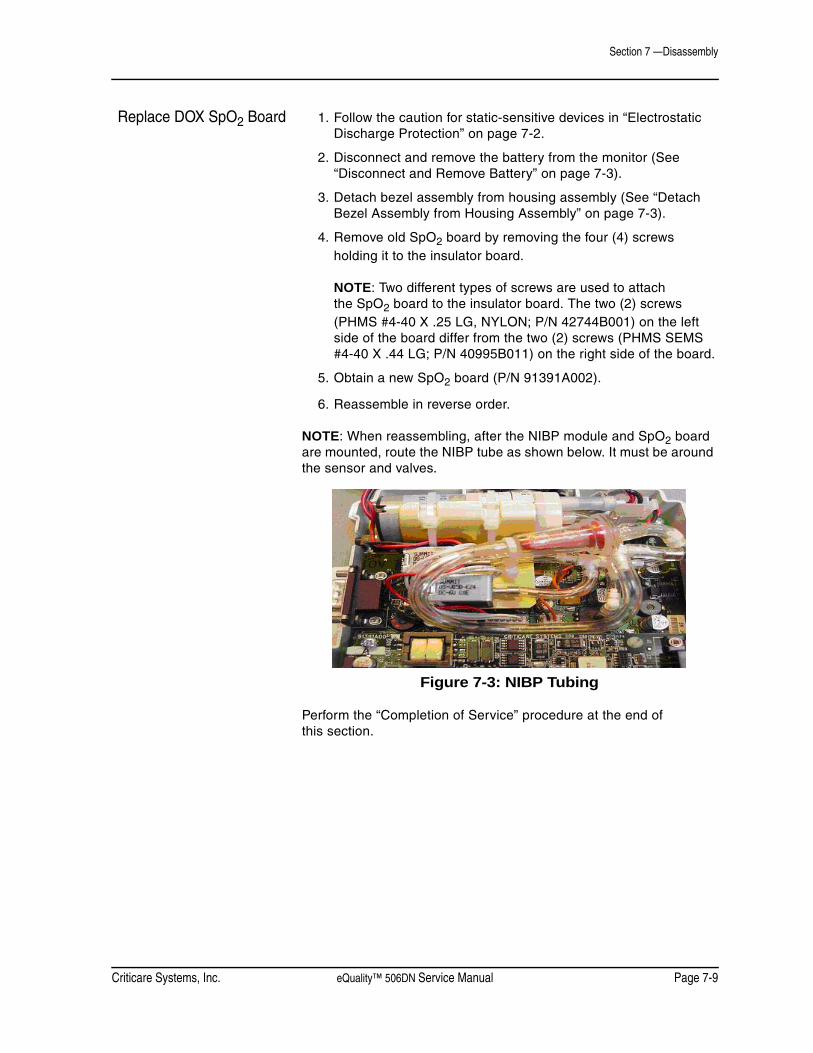
Criticare Systems, Inc. eQuality™ 506DN Service Manual Page 7-9
Section 7 —Disassembly
Replace DOX SpO2 Board 1. Follow the caution for static-sensitive devices in “Electrostatic Discharge Protection” on page 7-2.
2. Disconnect and remove the battery from the monitor (See “Disconnect and Remove Battery” on page 7-3).
3. Detach bezel assembly from housing assembly (See “Detach Bezel Assembly from Housing Assembly” on page 7-3).
4. Remove old SpO2 board by removing the four (4) screws holding it to the insulator board.
NOTE: Two different types of screws are used to attach the SpO2 board to the insulator board. The two (2) screws (PHMS #4-40 X .25 LG, NYLON; P/N 42744B001) on the left side of the board differ from the two (2) screws (PHMS SEMS #4-40 X .44 LG; P/N 40995B011) on the right side of the board.
5. Obtain a new SpO2 board (P/N 91391A002).
6. Reassemble in reverse order.
NOTE: When reassembling, after the NIBP module and SpO2 board are mounted, route the NIBP tube as shown below. It must be around the sensor and valves.
Figure 7-3: NIBP Tubing
Perform the “Completion of Service” procedure at the end of this section.

Section 7 —Disassembly
Page 7-10 eQuality™ 506DN Service Manual Criticare Systems, Inc.
Replace NIBP Module 1. Follow the caution for static-sensitive devices in “Electrostatic Discharge Protection” on page 7-2.
2. Detach bezel assembly from housing assembly (See “Detach Bezel Assembly from Housing Assembly” on page 7-3).
3. Detach the NIBP module from the main board by removing the two (2) screws (PHMS SEMS #4-40 X .44 LG; P/N 40995B009) located in the lower middle of the main board.
4. Disconnect the NIBP module’s ribbon cable from P3 on the main board.
5. Disconnect the NIBP module’s open tube from the SENS1 connector on the main board.
6. Disconnect the NIBP module from the NIBP fitting (P/N 42014B001) on the side panel (P/N 45225B001).
7. Obtain a new NIBP module (P/N 95597A005).
8. Reassemble in reverse order.
NOTE: When reassembling, after the NIBP module and SpO2 board are mounted, route the NIBP tube as shown below. It must be around the sensor and valves.
Figure 7-4: NIBP Tubing
Perform the “Completion of Service” procedure at the end of this section.

Criticare Systems, Inc. eQuality™ 506DN Service Manual Page 7-11
Section 7 —Disassembly
Housing Disassembly
Replace Power Supply 1. Follow the caution for static-sensitive devices in “Electrostatic Discharge Protection” on page 7-2.
2. Detach bezel assembly from housing assembly (See “Detach Bezel Assembly from Housing Assembly” on page 7-3).
3. Remove the three (3) screws (PMHS SEMS #4-40 X .25 LG; P/N 40995B005) holding the insulator (P/N 42740B002) to the power supply bracket and chassis.
4. Pull out the power supply and bracket and disconnect the power supply cable (P/N 90927A003) from CON 2 on the power supply.
5. Disconnect the AC power inlet cable from CON 1 on the power supply.
6. Disconnect the ground wire from the AC inlet cable from the power supply bracket by removing the keps nut (P/N 40284B002).
7. Disconnect the power supply from the bracket (P/N 45213B001) by removing the four (4) screws (PHMS 4-40 X .438 SEMS; P/N 40995B011) holding them together.
8. Obtain a new power supply (P/N PWRS10000).
9. Reassemble in reverse order. See assembly drawings for torque instructions.
Perform the “Completion of Service” procedure at the end of this section.
Section 7 —Disassembly
Page 7-12 eQuality™ 506DN Service Manual Criticare Systems, Inc.
Completion of Service 1. Verify all connections are secure.
2. Reconnect the battery (See “Disconnect and Remove Battery” on page 7-3).
3. Perform the functional tests in “Functional and Safety Testing” in Section 5.
4. Perform the electrical safety tests in “Electrical Safety Tests” in Section 5.

Criticare Systems, Inc. eQuality™ 506DN Service Manual Page 8-1
Section 8 — Troubleshooting
Troubleshooting Guide
Symptom Problem Solution
Unit won’t power up • Battery is discharged• No AC power at outlet• Main power fuse is blown• Poor keypad cable connect• Bad keypad switch• Bad Main Board
Connect AC power cordUse alternate outletReplace power fuse(s) by the AC inputReposition ribbon cable into Main BoardReplace keypad membraneReplace Main Board and software
Monitor shuts off • Automatic shutoff after 30min.• Drained battery• Bad software• Bad Main Board
Press the ON/OFF keyConnect to AC powerUpdate softwareReplace Main Board and reprogram
Functions not available
• Default settings wrong• Incorrect software• Degraded software
Return to factory default settingsUpdate softwareReplace software
LCD display blank • Contrast is misadjusted
• Bad LCD Board connection• Bad LCD Board
Adjust CONTRAST in the CONFIGURATION menuCheck pins and reconnectReplace LCD Board
Leaks in NIBP system • Defective cuff• Defective hose• Damaged/loose NIBP fitting• Stripped insulator• Leaky pneumatics & pump
Replace cuffReplace hoseReplace/tighten Quick-Connect fittingReplace nylon insulator and O-ringReplace NIBP mechanical assembly
Fails performance test • Leaks in NIBP system• Poor calibration• Defective pump or valves• Bad transducer
See aboveRecalibrate NIBPReplace NIBP mechanical assemblyReplace NIBP mechanical assembly
NIBP not functioning • NIBP module turned off
• Bad NIBP switch• Pump not running• Failed pump motor• Bad Main Board• Bad NIBP Board
Turn on NIBP in the CONFIGURATION menu orensure 1020 is selected for the NIBP setting in BOARD SETUPS in the service menu.Check pump wires to NIBP BoardCheck pins on NIBP Board & reconnectReplace pumpReplace Main Board and softwareReplace NIBP Board and software

Section 8 —Troubleshooting
Page 8-2 eQuality™ 506DN Service Manual Criticare Systems, Inc.
SpO2 not functioning. • Using incorrect sensor.
• SpO2 module turned off
• Bad sensor• SpO2 board disconnected• Bad SpO2 board• Bad Main Board/SpO2 Cable
Verify the correct sensor is used for the monitorTurn on SpO2 in the CONFIGURATION menu or ensure the proper setting is selected for the SPO2 setting in BOARD SETUPS in the service menu. Replace sensor.Reconnect SpO2 boardReplace SpO2 boardReplace Main Board/SpO2 Cable
Unit intermittently missing blood pressure measurements
• Cuff size changed• Wrong cuff size or poor/loose cuff
placement• Poor connection of NIBP module
• Incorrect Patient Size selected
Unit adapts to cuff size on next attemptCheck cuff selection and placement
Check pins and clean connection of the NIBP module to the Main Board or replace module/board if necessary.Change patient size
No sound from speaker
• Speaker wire disconnected• Speaker wire broken• Bad Main Board
ReconnectReplace speakerReplace Main Board
No communications • Serial settings not correct• Bad serial cable (external)• Bad Main Board
Check MENU settingsReplace external serial cableReplace Main Board
Symptom Problem Solution

Criticare Systems, Inc. eQuality™ 506DN Service Manual Page 9-1
Section 9 —Drawings and Schematics
List of Drawings
Assembly Parts Lists Title Drawing Number
FINAL AY 506DN DOX 93987A001
NIBP MODULE 6 PIN CONN 95597A005
506DN MONITOR CAT 506DN-X
PCB Drawing List PCB AY DIG SPO2 91391A002
PCB AY DIG SPO2 SCHEMATIC 91391S002
506CN MAIN BOARD 91410A001
506DN MAIN BOARD SCHEMATIC 91410S001
Section 9 —Drawings and Schematics
Page 9-2 eQuality™ 506DN Service Manual Criticare Systems, Inc.
506DN Final Assembly 93987A001 FINAL AY 506DN DOX
Item # CSI Part # Description01 91410A001 PCB AY, 506CN MAIN BOARD02 42742B001 STANDOFF M/F #4-40 X .375 LG NYLON03 42743B001 HEX NUT #4-40 NYLON04 42744B001 P.H.M.S. #4-40 X .25 LG NYLON06 42740B002 INSULATOR CHASSIS07 42740B001 INSULATOR DOX MAIN BRD08 91391A002 PCB AY, DIG SPO2, 506DN09 95597A005 NIBP MODULE 6 PIN CONN10 45225B001 SIDE PANEL11 42014B001 FITING, QUICK CON. HH NIBP12 40995B011 P.H.M.S. 4-40 X .438 SEMS13 40284B005 NUT 10-32 KEPS PL14 45211B001 BEZEL 506CN15 45214B001 MEMBRANE 506CN16 81521B001 DISP/LCD PNL GRAPHIC/320X24017 42127B004 WINDOW FILTER 506CN18 83401B002 EMI SHIELD21 40995B005 P.H.M.S. 4-40 X .25 SEMS22 95257A003 SPEAKER CABLE AY 1.5” DIA23 90929A001 CABLE ASSY BATTERY TO MAIN BRD24 45210B001 HOUSING 506CN25 87277B001 FOOT .50 OD X .19 H26 40284B001 NUT 4-40 KEPS PL27 83476B001 AC POWER INLET28 82013B001 FUSE TIME LG 500MA L 250V 5X2029 42064B003 F.H.M.S. 4-40 X .312 PH PL30 90968A005 CABLE AY AC INLET31 41158B001 TERMINAL EQUIPOTENTIAL32 41164B001 NUT M6 X 1.0 KEPS PL33 90927A003 CABLE AY POWER SUPPLY TO MAIN BD34 PWRS10000 PWRSUP 40W 9VDC 90-264VAC 47-63 HZ35 45213B001 BRACKET POWER SUPPLY36 83378B001 SHOCK PAD .75DIA X .188TH38 42435B002 P.H.M.S. 6-32 X .375 316SS39 MISC10004 BATT/LA 6V 4.5AH 70X48X110MM40 45212B001 BATTERY DOOR 506CN41 42745B001 F.H.M.S. #4-40 X .25 COATED GREY43 40284B002 NUT 6-32 KEPS PL44 40067B001 CABLE TIE 4.045 40294B001 HOLDER TIE WRAP ADH-BK SM46 40132B001 TAPE MICROFOAM ADH-BACKED47 41157B001 THRDLOCK ASSURE SURF CUR48 41891B004 DUST COVER, CLEAR, DB9P49 40995B009 P.H.M.S. 4-40 X .625 SEMS
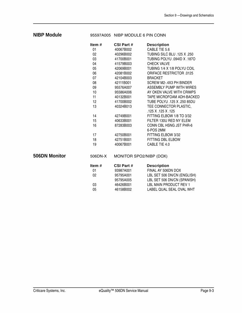
Criticare Systems, Inc. eQuality™ 506DN Service Manual Page 9-3
Section 9 —Drawings and Schematics
NIBP Module 95597A005 NIBP MODULE 6 PIN CONN
Item # CSI Part # Description01 40067B002 CABLE TIE 5.602 40296B002 TUBING SILC BLU .125 X .25003 41700B001 TUBING POLYU .094ID X .187O04 41579B003 CHECK VALVE05 42069B001 TUBING 1/4 X 1/8 POLYU COIL06 42081B002 ORIFACE RESTRICTOR .012507 42104B003 BRACKET08 42111B001 SCREW M2-.4X3 PH BINDER09 95576A007 ASSEMBLY PUMP WITH WIRES10 95586A006 AY OKEN VALVE WITH CRIMPS11 40132B001 TAPE MICROFOAM ADH-BACKED12 41700B002 TUBE POLYU .125 X .250 85DU13 40324B013 TEE CONNECTOR PLASTIC,
.125 X .125 X .12514 42749B001 FITTING ELBOW 1/8 TO 3/3215 40633B001 FILTER 130U RED NY ELEM16 87283B003 CONN CBL HSNG JST PHR-6
6-POS 2MM17 42750B001 FITTING ELBOW 3/3218 42751B001 FITTING DBL ELBOW19 40067B001 CABLE TIE 4.0
506DN Monitor 506DN-X MONITOR SPO2/NIBP (DOX)
Item # CSI Part # Description01 93987A001 FINAL AY 506DN DOX02 95795A001 LBL SET 506 DN/CN (ENGLISH)
95795A005 LBL SET 506 DN/CN (SPANISH)03 46426B001 LBL MAIN PRODUCT REV 105 46158B002 LABEL QUAL SEAL OVAL WHT

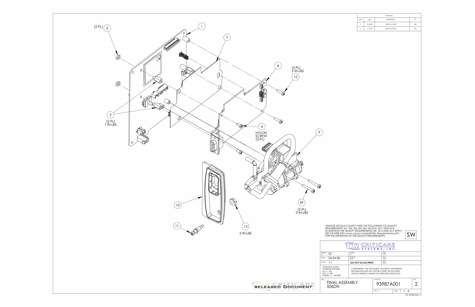
1
8
1049
12
11 13
(2-PL)5 IN-LBS
(2-PL)5 IN-LBS
5 IN-LBS
3
7
(2-PL)
2
(2-PL)1 IN-LBS 4
NYLONSCREW(2-PL)
9
REV.
SHEETDIST:
PART NO.:
APPR.:MFG.
APPR.:Q.A.
APPR.:ENG.
WITHOUT WRITTEN CONSENT OF CRITICARE SYSTEMS, INC.INFORMATION AND MAY NOT BE COPIED OR DIVULGEDCONFIDENTIAL: THIS DOCUMENT CONTAINS CONFIDENTIAL
DO NOT SCALE PRINT
REVISIONS
REV.
DRAWN BY:
DATE:
SCALE:
TOLERANCE UNLESSOTHERWISE SPECIFIED:XX: +/- .020XXX: +/- .005ANGLES: +/- 1 DEGREE
CHECKBY:
RELEASEDATE:
DO NOT SCALE PRINT
TITLE:
21 4
SC04-04-081:1
-
FINAL ASSEMBLY506DN 93987A001
DATE DESCRIPTION BY
OF
SWVENDOR SHOULD COMPLY WITH THE FOLLOWING CSI QUALITYREQUIREMENTS: Q1, Q2, Q4, Q5, Q6, Q7,Q10, Q11 AND Q16.IN ADDITION THE QUALITY REQUIREMENTS Q9, Q13 AND Q17 APPLY.SEE CSI WEB SITE ( www.csiusa.com/pdf/QA_Requirements.pdf )FOR THE DEFINITION OF THE QUALITY REQUIREMENTS.
CSI #0385 Rev. 0
1 DBLSEE ECN #103089/18/08
2 1/13/09 SEE ECN #10359 DBL
released Document
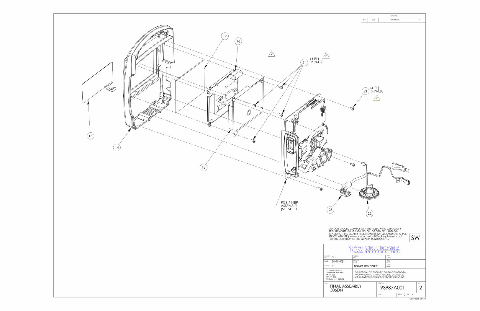
15
14
1716
21
22
(4-PL) 5 IN-LBS
21(4-PL) 2 IN-LBS
23
PCB / NIBP ASSEMBLY(SEE SHT. 1)
18
2
22
REV.
SHEETDIST:
PART NO.:
APPR.:MFG.
APPR.:Q.A.
APPR.:ENG.
WITHOUT WRITTEN CONSENT OF CRITICARE SYSTEMS, INC.INFORMATION AND MAY NOT BE COPIED OR DIVULGEDCONFIDENTIAL: THIS DOCUMENT CONTAINS CONFIDENTIAL
DO NOT SCALE PRINT
REVISIONS
REV.
DRAWN BY:
DATE:
SCALE:
TOLERANCE UNLESSOTHERWISE SPECIFIED:XX: +/- .020XXX: +/- .005ANGLES: +/- 1 DEGREE
CHECKBY:
RELEASEDATE:
DO NOT SCALE PRINT
TITLE:
22 4
SC04-04-081:1
-
FINAL ASSEMBLY506DN 93987A001
DATE DESCRIPTION BY
OF
SWVENDOR SHOULD COMPLY WITH THE FOLLOWING CSI QUALITYREQUIREMENTS: Q1, Q2, Q4, Q5, Q6, Q7,Q10, Q11 AND Q16.IN ADDITION THE QUALITY REQUIREMENTS Q9, Q13 AND Q17 APPLY.SEE CSI WEB SITE ( www.csiusa.com/pdf/QA_Requirements.pdf )FOR THE DEFINITION OF THE QUALITY REQUIREMENTS.
CSI #0385 Rev. 0
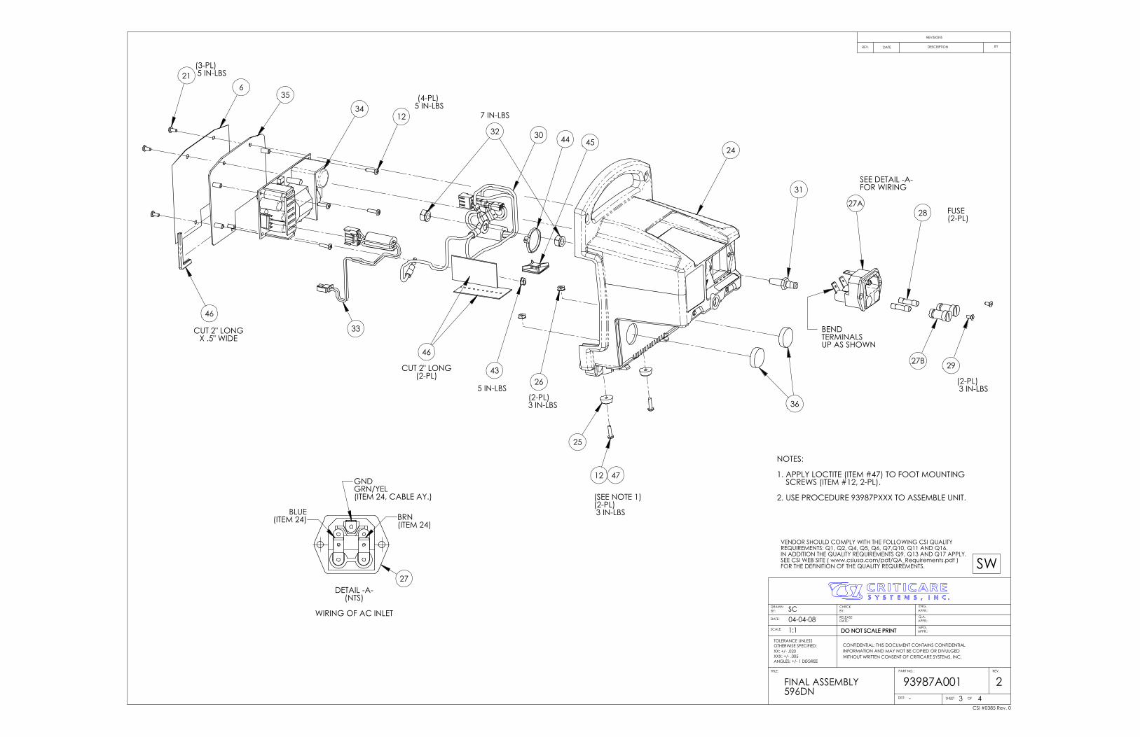
24
25
(SEE NOTE 1)(2-PL) 3 IN-LBS
12
(4-PL) 5 IN-LBS
26
21(3-PL) 5 IN-LBS
27A
27B
28 FUSE(2-PL)
29
(2-PL) 3 IN-LBS
31
32
33
34
35
36
SEE DETAIL -A-FOR WIRING
BEND TERMINALSUP AS SHOWN
30
(2-PL)3 IN-LBS
46
CUT 2" LONGX .5" WIDE
6
7 IN-LBS
43
5 IN-LBS
44 45
12 47
NOTES:
1. APPLY LOCTITE (ITEM #47) TO FOOT MOUNTING SCREWS (ITEM #12, 2-PL).
2. USE PROCEDURE 93987PXXX TO ASSEMBLE UNIT.
46
CUT 2" LONG(2-PL)
GNDGRN/YEL(ITEM 24, CABLE AY.)
BRN(ITEM 24)
BLUE(ITEM 24)
27DETAIL -A-
(NTS)
WIRING OF AC INLET
REV.
SHEETDIST:
PART NO.:
APPR.:MFG.
APPR.:Q.A.
APPR.:ENG.
WITHOUT WRITTEN CONSENT OF CRITICARE SYSTEMS, INC.INFORMATION AND MAY NOT BE COPIED OR DIVULGEDCONFIDENTIAL: THIS DOCUMENT CONTAINS CONFIDENTIAL
DO NOT SCALE PRINT
REVISIONS
REV.
DRAWN BY:
DATE:
SCALE:
TOLERANCE UNLESSOTHERWISE SPECIFIED:XX: +/- .020XXX: +/- .005ANGLES: +/- 1 DEGREE
CHECKBY:
RELEASEDATE:
DO NOT SCALE PRINT
TITLE:
23 4
SC04-04-081:1
-
FINAL ASSEMBLY596DN
93987A001
DATE DESCRIPTION BY
OF
SWVENDOR SHOULD COMPLY WITH THE FOLLOWING CSI QUALITYREQUIREMENTS: Q1, Q2, Q4, Q5, Q6, Q7,Q10, Q11 AND Q16.IN ADDITION THE QUALITY REQUIREMENTS Q9, Q13 AND Q17 APPLY.SEE CSI WEB SITE ( www.csiusa.com/pdf/QA_Requirements.pdf )FOR THE DEFINITION OF THE QUALITY REQUIREMENTS.
CSI #0385 Rev. 0
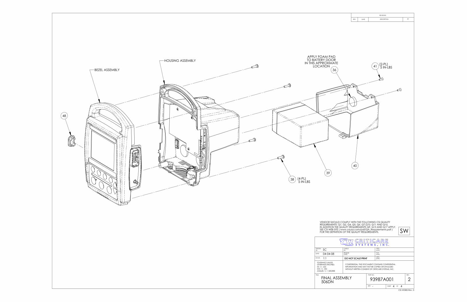
BEZEL ASSEMBLY
HOUSING ASSEMBLY
38 (4-PL) 5 IN-LBS
36
39
40
APPLY FOAM PADTO BATTERY DOOR
IN THIS APPROXIMATELOCATION 41 (2-PL)
5 IN-LBS
48
REV.
SHEETDIST:
PART NO.:
APPR.:MFG.
APPR.:Q.A.
APPR.:ENG.
WITHOUT WRITTEN CONSENT OF CRITICARE SYSTEMS, INC.INFORMATION AND MAY NOT BE COPIED OR DIVULGEDCONFIDENTIAL: THIS DOCUMENT CONTAINS CONFIDENTIAL
DO NOT SCALE PRINT
REVISIONS
REV.
DRAWN BY:
DATE:
SCALE:
TOLERANCE UNLESSOTHERWISE SPECIFIED:XX: +/- .020XXX: +/- .005ANGLES: +/- 1 DEGREE
CHECKBY:
RELEASEDATE:
DO NOT SCALE PRINT
TITLE:
24 4
SC04-04-081:1
-
FINAL ASSEMBLY506DN 93987A001
DATE DESCRIPTION BY
OF
SWVENDOR SHOULD COMPLY WITH THE FOLLOWING CSI QUALITYREQUIREMENTS: Q1, Q2, Q4, Q5, Q6, Q7,Q10, Q11 AND Q16.IN ADDITION THE QUALITY REQUIREMENTS Q9, Q13 AND Q17 APPLY.SEE CSI WEB SITE ( www.csiusa.com/pdf/QA_Requirements.pdf )FOR THE DEFINITION OF THE QUALITY REQUIREMENTS.
CSI #0385 Rev. 0

FINISHED ASSEMBLY
(4-PL)(TORQUE
TO 2 IN LBS)
TO V1
123
7
16
10
6.00"LONG
.50"LONG .75"
LONG.75"
LONG
611
5
2
4
1
1.00"LONG1.50"
LONG
.75"LONG
(2-PL)
INSTALL WITHARROW POINTING
AWAY FROMPUMP
13
V1
V2
TO V2
CONNECTORHOUSING
CONNECTORHOUSING
87283B003(JST PHR-6)
PUMP AY
CONNECTOR WIRING DETAIL
NOTES:
1. REFER TO ASSEMBLY PROCEDURE FOR 95597P005 ASSEMBLY SEQUENCE AND INSTRUCTIONS.
VALVE AY(2-PL)
9
3
17
3 18 3
14
3
12
1.25" LONG
1.50" LONG
8
1.00"LONG
5
.75"LONG
15
19
BLK (2)
RED (1)
(3,4)
(5,6)
6
1
RED - PUMP +
BLK - PUMP -
16
WHT V2WHT V1
REV.
SHEETDIST:
PART NO.:
APPR.:MFG.
APPR.:Q.A.
APPR.:ENG.
WITHOUT WRITTEN CONSENT OF CRITICARE SYSTEMS, INC.INFORMATION AND MAY NOT BE COPIED OR DIVULGEDCONFIDENTIAL: THIS DOCUMENT CONTAINS CONFIDENTIAL
DO NOT SCALE PRINT
REVISIONS
REV.
DRAWN BY:
DATE:
SCALE:
TOLERANCE UNLESSOTHERWISE SPECIFIED:XX: +/- .020XXX: +/- .005ANGLES: +/- 1 DEGREE
CHECKBY:
RELEASEDATE:
DO NOT SCALE PRINT
TITLE:
01 1
SC04-04-081:1
-
NIBP MODULE6 PIN CONN 95597A005
DATE DESCRIPTION BY
OF
SWVENDOR SHOULD COMPLY WITH THE FOLLOWING CSI QUALITYREQUIREMENTS: Q1, Q2, Q4, Q5, Q6, Q7,Q10, Q11 AND Q16.IN ADDITION THE QUALITY REQUIREMENTS Q9, Q13 AND Q17 APPLY.SEE CSI WEB SITE ( www.csiusa.com/pdf/QA_Requirements.pdf )FOR THE DEFINITION OF THE QUALITY REQUIREMENTS.
CSI #0385 Rev. 0
released Document
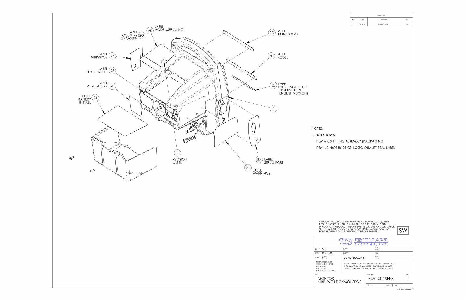
2D
2C
2E
2A
2J
2H
2B
2G2K
2F
1
LABELSERIAL PORT
LABELNIBP/SPO2
LABELFRONT LOGO
LABELMODEL
LABELWARNINGS
LABELELEC. RATING
LABELCOUNTRY
OF ORIGIN
LABELREGULATORY
LABELBATTERYINSTALL
LABELMODEL/SERIAL NO.
2L LABELLANGUAGE MENU(NOT USED ON ENGLISH VERSION)
3
REVISIONLABEL
NOTES:
1. NOT SHOWN:
ITEM #4, SHIPPING ASSEMBLY (PACKAGING)
ITEM #5, 46036B101 CSI LOGO QUALITY SEAL LABEL
REV.
SHEETDIST:
PART NO.:
APPR.:MFG.
APPR.:Q.A.
APPR.:ENG.
WITHOUT WRITTEN CONSENT OF CRITICARE SYSTEMS, INC.INFORMATION AND MAY NOT BE COPIED OR DIVULGEDCONFIDENTIAL: THIS DOCUMENT CONTAINS CONFIDENTIAL
DO NOT SCALE PRINT
REVISIONS
REV.
DRAWN BY:
DATE:
SCALE:
TOLERANCE UNLESSOTHERWISE SPECIFIED:XX: +/- .020XXX: +/- .005ANGLES: +/- 1 DEGREE
CHECKBY:
RELEASEDATE:
DO NOT SCALE PRINT
TITLE:
11 1
SC04-10-08NTS
-
MONITORNIBP, WITH DOX/SQL SPO2
CAT 506XN-X
DATE DESCRIPTION BY
OF
SWVENDOR SHOULD COMPLY WITH THE FOLLOWING CSI QUALITYREQUIREMENTS: Q1, Q2, Q4, Q5, Q6, Q7,Q10, Q11 AND Q16.IN ADDITION THE QUALITY REQUIREMENTS Q9, Q13 AND Q17 APPLY.SEE CSI WEB SITE ( www.csiusa.com/pdf/QA_Requirements.pdf )FOR THE DEFINITION OF THE QUALITY REQUIREMENTS.
CSI #0385 Rev. 0
1 DBLSEE ECN #103591/14/09

released Document
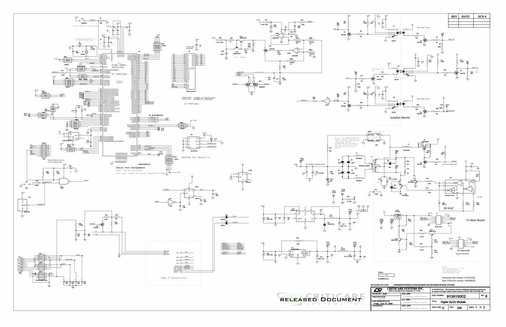
������
��������
�����
� �� ��
� �����
�������
���
������
��
�����
� �
���
������
������
���
� �� ��
�����������
���������������
�����
���������
���� ���
�������
����������
�!�
�������
�!"
�!�
�!�
������
�������
�!"�!��!��!�
������
�������������
���� ���� � ��
����
���
���
����
� ��
�������
��� �
��� �
� �������
������
���� ����
���� ����
���� �������� ����
�������"
�#�!�$�%
�����"�&�'
��$��%������
��!
��'��#
�����"
��
�#�!�$�%
�
�����
�������
����
��
�������������
� ��
�
��
�
������ ����
���
����� ������
����������������
�����
������������
���� ��� ���� ���������������
����� ���
������� �����
�������������������������� ��������
���� ���� � �� ��� �
�#�!�$�%�������"
��#��'
��"�&
�%
��%��$
���
��!
�$
���
�#
�"
��
�!
��
�'
��
���
�$�
�����
����
�����
� �� ��� �� ��
�$�
������
������
��(��
��(��
��(��
��(��
��(��
��(��
��(��
��(��
��(��
��(��
��(��
��(��
��(��
$�
�
���
�
�
�
$�
����
��(��
����
�$�
����
�$�
$�
�
���
�
�
�
�
�
�
��
��
�
�
$�$�$�
$�
��(�� ��(�� ��(��
��(��
��(��
�
��(��
�
$�
��(�� ��(�� ��(��
��(��
��(��
$�
�$�
�$�
�$�
�$�
�$�
����
����
�
�
�
���
��� ��� �$�
�
���
�
$���
$���
��(��
� ���� �� �����
�$�
����
�$�
����
�� ����������
�����
��������
��� ���� ������ ���� ������ ���� ���
����������������� � ��������������������������������� !"
�#$������%&��������'�()��()��(���(*���()����(*��'�)��(�(�'�+(�),���-�������.��/��0�)���)0��))�(��(��()�*���������121��31��4
����52&
������#����&
%�1�3#��$�������&
�6��7��52&
�84�99�4
:4�4�99�4
3$84�99�4
9���;35��& ���4
���%�&
16���1�<�& ��1�& 16��� #$
�%����#��$�%��3�&
�
�)*)+,-.�/ �.012-3
&��&��""�
456���6�� �. ����.7� �86��������6&��&��""�6&��&��""����"(��
�9)1,:;.42<3.�#;.�""'
� ��
�4�
�"!
������
��� � ������� ��������
������������ ���������������������������������
����������������������
� �������� ��������� !������ ����"������������ �
#$%&�'
6�)�����'���)����((��)��=*����.���-'�()#(�+>
$%�16? 6@�$$$$6=��"7>
���? '�='�A>
���?� '�='�A>
=� �75A!>B @B�$$$$
(�
�==3>?-:.�,9+.<2>?395.&��&��""��,93.���.�,9+.<2>?395.'�!%!�""�
�0.,)<.�0,91
���.�2993<+.@&($.>,
)&%�(�������*+�,-
..�=0-,+)0<.�,99)39
.�./)�0��
�$.�
�"�. ���.����������
.
%(��������%((��1�����
%(��������%(�(��1�������#$%����� " �2��������������������0�����������3������� ����������������������������0���4���- ����� �1 �� 0�����������-����������������5� ��� ���6,����-����� �������������������������� ���7�
$".���
+.A.�(���
�0B.�29<=.012-3.C ��C
��(��.D.!"">,
����������� ������� 8(9����%%(����������3 ��8(9���:����� ���� ������� �9����3 ������# ��
= �!75A!>���.�2993<+.@&($.>,
9��� �;�-����3����-� �����-���
&&�<$#�3���:� ���9%
)&%�(4��)#4=!�#
($##$���$%&
B� @B�$$$$=��)��(�)�>=�(�)�����-��)>
.�>!��?
�
E2,=,9.�0<<3F+09
�����.�� ��������
<#
� 0��>�(����������
&)&(4<$�9())@�89A�&%�9��$#�9�@
&)&(4<$�9())@�89A�&%�9��$#�9�@
&)&(4<$�9())@�89A�&%�9��$#�9�@
��&
#�"%
��&
#�"%
� %
E�'��%%"�
E�'��%%"�
�
��
(�
��"
(�
��" ��
�!�""����!�""���
��
%�
���%#���%#
��
��
��!%����'��&���
��
��!%����'��&���
���
$����
#!
���
��
����##�����#'��#�"���'"����$����%�"�������#�
���� #$
��"����E'' ��������'#
� #%
��$�����$'��%����"$#
���
�%
���
!
���
$&���
#&
���
�$
���
�'
�!$���E� ���!!���!���E� �"�!#���#����E� �&
��!��� '���$��� '���%���� '%������� '$
�����������������E"'!
������& ��������' ��������# ����"���! �"��#���$ �&��!���% �'��$���� �#��%���� �!������� �%������" �������& ����"��' ����#��# �"��!��! &��$��$ '��%��% #������ $������ %������ ���"��" ���#���$ $���!���% $"��$���� %&��%���� %'������� %!������" %$�����& %%��"��' %���#��# %���!��! %���$��$ %"��%��% �&������ �#������ �!������ �$��"��" �%
��������$!�������"$$��������$%��"����"$�
�!������ !��!�����E� !�
��#�� #��� ��$�� �!%��!�� !��� ��$�� "!$��$�� $��� ��%�����!!��%�� %��� ��%�����!#����� ���� �������"!'
����� ���� ���#"
����"��� ��"�� '���"����������� ��"�� &��������������� ��"�� �"������"������� ��"�� �������"&�� ����� �����%�"'�������� ����� �����$�"#�� ����� �%���!�"!�������� ����� �$���#�"$
�#��%#�����"��!��%!���"�"��$��%$�""�%��%%&&����%�&'����%�&#����%�&!�"��%"&$
����&������"�����&%
��%���"���E% �$��$�������E$ �!��!�������E! �#��#�������E# �'
�!%���E" ��
���
�"%
�!�����"����$ !��!"����E"���% !"
��"�� "��� ���#�
�������
#�
���
�
���
'�
�$"��������E%'&�$���������E$&"
�$����������E#���������E &�
������" ��!
��"���% ��"������� ��&������� ��'������� ��#
�$���������E!&�
����� ���� ���!&
���
%#
���
�(""�
���
�(""�
� �
(���"(���"
��
�%!". ��%!". �
��
��$'�""���
��$'�""���
��
���
�(""�
���
�(""�
� �
E�#��%%"�E�#
��%%"�
�
� �
��#
�""
��#
�""
� �
��!��!
���%���%
E����"!
E����"!
�
��
���
�""
���
�""
��
�$$
�$
�$$
�$
�$&�$("�$&�$("
("%#�!"("%# ("%#�!"("%#
�'
�""��%
�'
�""��%
���%
'#!$
��$����$��
��
���
�"��%
���
�"��%
� � � %
' # ! $
��"%(&&���"%(&&�
��
����(""�����(""�
��
(�
�$#
(�
�$#
�$
�"��%
�$
�"��%
���%
'#!$
(�
��&
(�
��&
� �
��%��%
4��
��
4��
��
� �
��'
�""�
��'
�""�
� �
���$����$�
E����%%"�E����%%"�
��
�
�$�
�
�$�
�
��$
�(""�
��$
�(""�
� �
�� �""����� �""�����
%�
4�
�����"$�"��������
4�
�����"$�"��������
� �� %$ !# '& �"
E�
���"!
E�
���"!�
��
��������
E�����"!
E�����"!
�
��
���%����%�
��
�&
�"���
�&
�"���
��
%�
���$!���$!
��
���"���"
("����("����
� �
��&�"���&�"�
��
��$(���$(�
��
�$!�
�""��%(�G
�$!�
�""��%(�G
% $
(��!(�
�!
��
�#
�"���
�#
�"���
��
%�
������
��'��'
��
��'�.�.'.�� �
��
��'�.�.'.�� �
�"�"���&���'���#�%�!�$�$�!�%�#���'��&���"��
�� " ���� � ���� � ���� � �$�� % �!�� $ �#�� ! �'�� # �&
��%�� ���%
���������
��$#��!�"��!�&
�����$���"
��'�""���'
�""�
��
("����%("����% �
�
(����(�
���
��
E�!����"%E�!
����"%
�
�
�
��%(&&���%(&&�
��
�
��#!'2�.�"�
�
��#!'2�.�"�
��
4��
4����
4��
4����
� �
�%#���%#��
��
��#��#
���%(&&����%(&&�
��
�$
�""
�$
�""
��
���#���#
E%
���"!
E%
���"!�
��
�#
�&�%
�#
�&�%
��
��!
�""
��!
�""
��
�'
�""�
�'
�""�
��
�
���!'2�.�"�
�
���!'2�.�"�
��
��#
��
��#
��
��
(���(�
��
��
/��
A�%
�&
�#%����%"%
/��
A�%
�&
�#%����%"%
�
��
#
!
$
'
%
� ����(�2�.�$�
� ����(�2�.�$�
��
�&
��
�&
��
��
�'
��%�"%�'
�'
��%�"%�'
�"�
���
���
���%
��� '
���� #
��� !
��� $
��
�.����
��
�.����
��
�$�
�".$G.��"!
�$�
�".$G.��"!
� �
(����(�
���
��
���"���"
��%
�""�
��%
�""�
��
4:E�"��������
4:E�"��������
�
�%�
�% �"����% �"���
��
%�
���"����"�
��
�$�""2��$�""2�
� �
�����%#�������%#��
$�� �
%
� ��&�(�2�.�$�
� ��&�(�2�.�$�
��
��
!��!
��
!��!
�
�$
!#
'
(���%(���%
��
4�
��&
4�
��&
$&%'�#�!�
�!$%�(���!$%�(��
��
4�
'#�����"��
4�
'#�����"��
� �� %$ !# '& �"
����� ������ �
��'
�""�
��'
�""�
��
���#�"'���#�"'
�
�%
$
��������
��
��
(����(����
��
���"��%���"��%
� � � %
' # ! $
��'�
#%��#%
��'�
#%��#%
���
�����
E &
E '
��
�"��
��
���%!���%!
��
��
��� .��&!"�
��
��� .��&!"�
&
#
�
%�
$
���
��
���
��
���%$!#' &
�"�������%�$�!
�%
���%
�%
���%
��
�&�&���% $
!#'
���#� ����#� �
��&��&
��
���%
��
���%
��
�!!%�(���!!%�(��
��
E!���"!
E!���"!
�
��
�������������%�
". �
�%�
". �
�$'�(""��$'�(""�
�$!�
�""��%(�G
�$!�
�""��%(�G
�#
�$!�
�""��%(�G
�$!�
�""��%(�G
�!
E'���"!
E'���"!
�
��
��%
���'�'�
��%
���'�'�
����� �
���
���
�
�!
!��!
�!
!��!
�
�$
!#
'
E����%%"�
E����%%"�
��
�
�$/��'�$/��'
��
��%
�""
��%
�""
� �
��$&
�"".��
�$&
�"".�
��
��&�""���&
�""�
��
��
�""���
��
�""���
��
%�
���$����$�
�$!�
�""��%(�G
�$!�
�""��%(�G
� '
���!���!
��!�#(%���!�#(%�
��
��"�"�����"�"���
��
%�
���%(&&����%(&&�
��
�%%
�"�
�%%
�"�
�%$��"��%$��"�
��
�.����
��
�.����
� �
��"
�""
��"
�""
��
(���
(���
��
�$
#�"%
�$
#�"%
�%
������&$���������&$���
��'
���$��� �
�
%
� �� ���� ���� !�� #
�$�����%"�$�����%"
��
�'
���%
�'
���%
��
�!
�&�%
�!
�&�%
��
���!� ����!� �
����"�����"�
��������
���'���'
(���!(���!
��
�&". ��&". �
� �
�
���%#.�.� .����
���%#.�.� .����
�
��$
�%"
��$
�%"
��
�!"%(#$��!"%(#$�
��#�""���#�""�
��
�!�
%�(��
�!�
%�(��
� �
���$%���$%
���&� ����&� �
��"./���!��"./���!
��
�#
�%��"�$��(�
�#
�%��"�$��(�
��%
��
�
� �� $
��� ���
��(�:��:<&���."�
'�!%!�""�.�3H."
��(�:��:<&���."�
'�!%!�""�.�3H."
��$��$
E�$
��&&�$�
E�$
��&&�$�
�
' #� �
%
$!
�$�
�(""�
�$�
�(""�
� �
�' ������!�!"���%�' ������!�!"���%���% $
!#'
�%%#2��%
%#2�� �
E$
���"!
E$
���"!�
��
���"� ����"� �
� ��#%#.�.� .���
� ��#%#.�.� .���
��
� �$$�"2�
� �$$�"2�
��
�!
�%"
�!
�%"
��
(�
��$
(�
��$� �
(����(����
��
B
�
��"�
��'����
B
�
��"�
��'����
�
��
'%
�""/�
�!�
�""/�
�!�
�$/��#�$/��#
��
�%"�""��%"�""�
��
E�%
���"!
E�%
���"!�
��
��"��"���% $
!#'
��&
". �
��&
". �
� �
��
���%
��
���%
��
���"%#.�.� .���
���"%#.�.� .���
��
��
��
��
��
� ��%
���%
��
��
(���'(���'�
�
�!��"��!��"�
��
��"����"��
��
������
���$� ����$� �
�%
!��!
�%
!��!
�
�$
!#
'
�#
�""
�#
�""
��
��'�
#%��#%
��'�
#%��#%
��
����
E $
E !
��
%��
�
(���%(���%�
�
B
���"�
��'����
B
���"�
��'����
$
!#
���%$���%$
��
�%��""��%��""�
�%�
�&(��
�%�
�&(��
(����(����
��
���$���$
�!%%�(���!%%�(��
��
���� .� ��
�� .�� ��
��
��
���� .� ��
�� .�� ��
��
��
�%
��"
'
��
�".�I
��
�".�I ��
��
���%
��
���%
��
E�
���"!
E�
���"!�
��
��������
�$#�"��$#�"�
���
�""
���
�""
��
(�
�$
(�
�$ ��
��"��!#���(���"
��!#���(�
��#
� ��$
��
!
�=B '
�? ���
�
� �
�
��%
(""�
��'
(""�
��'��
����������������
��!
�%"
��!
�%"
� �
(��%(��%
��
���
������!�!"���%
���
������!�!"���%
���% $
!#'
������
(���(���
��
(����$(����$
��
���'� ����'� �
4:
E&��������
4:
E&��������
�
�%�
��%�"���%�"�
��
��������
���%'���%'
��
�&(��&(�
��
�!#
�#(%�
�!#
�#(%�
� �
���$� ����$� �
��
�.����
��
�.����
� �
E#��&%�$�� E#
��&%�$�� '#!$
%
���
�$%
�".$G.��"!
�$%
�".$G.��"!
� �
�!��""��!��""�
��
released Document

$
$
%
%
�
�
�
�
�
�
� �
� �
� �
� �
��
�����
���
��"
���
�����
���
�����
��
����
���������
�������$��$�
������ ��
�����
��������� ������ ���� �
����
����
�����
�����"
� �� ��� �� ��
������
����
��(��
�
���
�
��(��
���
��(��
�
���
�
�
�
���
�
�
�
�
�
�
�
�
��(���$�
�$�
�
���
��(��
��(��
���
�
���
��(��
�
��(��
%�
%�
%�
%�%�%�
�
�� ��
�����������$��$�
����
����
��������
� ���� �� �����
� �������������������������������� !" �#$������%&��������'�()��()��(���(*���()����(*��'�)��(�(�'�+(�)
,���-�������.��/��0�)���)0��))�(��(��()�*���������121��31��4
����52&
%�1�3#��$�������&
�6��7��52&
�84�99�4
:4�4�99�4
3$84�99�4
9���;35��& ���4
���%�&
16���1�<�& ��1�& 16��� #$
�%����#��$�%��3�&
9�5;35��&��0/:9)*J+.......
"� �.���.�90F3==09
&��&��""�
456���6�� �. ����.7� �86��������6&��&��""�6&��&��""����"(��
� �
�4�
�"! �
'�!%!�""�.�"
�31<3=1,:;.42<3.�';.�""'
�""'
������ ����� .�����.�. ��
������ ����� .�����.�. ��
������ ����� .�����.�. ��
�B0.�!?)+.���=.19)H3<.)<./2=J�/2--.K09.�#?)+93=0-2+)0<.7B)+J02+.0H39=,>/-)<*8
�90>./J0+01)013(
�09.-0B3=+.<0)=3;.+J)=.=:=+3>.)=./0B3931.K90>+J3.� �./F?.,<,-0*.$�(
�L+39<,-.93K393<F3.)=.M2)3+39.+J,<.)<+39<,-N.*)H3=�'?)+.<0)=3�K933.9,<*3.B)+J.L��.0H39=,>/-)<*(
�)<*-3.*902<1./-,<3.O2<F+)0<
�'"$��"�#.� .�90==?,9.=3++)<*=5��������������������������������������������������...�"("...���;.����...�"(�...���;.,=+39.)<��-,H3.02+...�"(�...���;.,=+39.02+��-,H3.)<...�"(�...��"P...�"(%...���P
� 0����(����������
�!$�""<��$��"G�#�
�!$�""<��$��"G�#�
������&'$��(�
������&'$��(�
��� � �� $
��
�
� ���
� �
%
�!&
$��� �G
�!&
$��� �G
���
����&�
���
����&�
��� % ��� �
��
$
��
����
��������
�#"�""<��$��"G�#�
�#"�""<��$��"G�#�
�#�
�"� �G
�#�
�"� �G
�#%�"���G
�#%�"���G
�!'�"��G
�!'�"��G
�!'�"2� !���"G
�!'�"2� !���"G
C4A�%&: A
����������
���
��� ���
����� ������������ ����
�������
���������� !�"
���� �#�� !�"
��$�
��������
���������� ��
���������
%&&
�'� ��
� ����
(&�
���"7�!.?)+8
L� �3K�(�$�
�3K�(�$�
���"7�!.?)+8
L�
�3K�($�
��)�*
��)�*
��)�*
��
���
���
�'"$��"!#C4A�%&: A
����������
���
��� ���
����� ������������ ����
�������
���������� !�"
���� �#�� !�"
��$�
��������
���������� ��
���������
%&&
�'� ��
� ����
(&�
���"7�!.?)+8
L� �3K�(�$�
�3K�(�$�
���"7�!.?)+8
L�
�3K�($�
��)�*
��)�*
��)�*
��
���
���
�'"$��"!#
�"(" $��"(� $"�"(� %&�"(� %'�"(% %#�"($ %!�"(! %$�"(# %%
��(" ����(� ����(� ����(� �"��(% �&��($ �'��(! �$��(# �%
��(" %���(� %���(� %���(� �'��(% �#��($ �!��(! �$��(# �%
�����"&
������'
�% !%�� !��� $&�� �#
����!�
���$
����"�$
�����"�!
������
���"��
����
�&
����
��
����"�%
������
��"���
����%
��"��
���"�"
����#
����
�'
�$ !"
����
�#
����
�&
����
$%
����
�!
����
%"
����
$$
����!
����
��
�����
�"
�����
��
� !�
���P $'
��� $��� $���� $!�� $#
��������#��""<��$��"G�#�
�#��""<��$��"G�#�
�!�
�""<��$��"G�#�
�!�
�""<��$��"G�#�
�!�
�""<��$��"G�#�
�!�
�""<��$��"G�#�
��
��
B
� �����'!"$
��
��
B
� �����'!"$
�
%�
$�
4%
�,>+3F.���.�L%L"("$)<.��.H39+./,==�+J92
�������
4%
�,>+3F.���.�L%L"("$)<.��.H39+./,==�+J92
�������
��$
�%!
# '
�!!�"<��!��"G�#�
�!!�"<��!��"G�#�
�#�
�"� �G
�#�
�"� �G
�#�
�""/�$"�$G � �
�#�
�""/�$"�$G � �
�#��"��G
�#��"��G
�#"�"��G
�#"�"��G
�#!�"��G
�#!�"��G
��
��
B
� ��%��'!"$
��
��
B
� ��%��'!"$
�
%�
$�
�#$
�"� �G
�#$
�"� �G
�!#�2��"�
��"G�'"G
�!#�2��"�
��"G�'"G
�!&�"2� !���"G
�!&�"2� !���"G
�#��""<��$��"G�#�
�#��""<��$��"G�#�
�!%
�""<��$��"G�#�
�!%
�""<��$��"G�#�

released Document
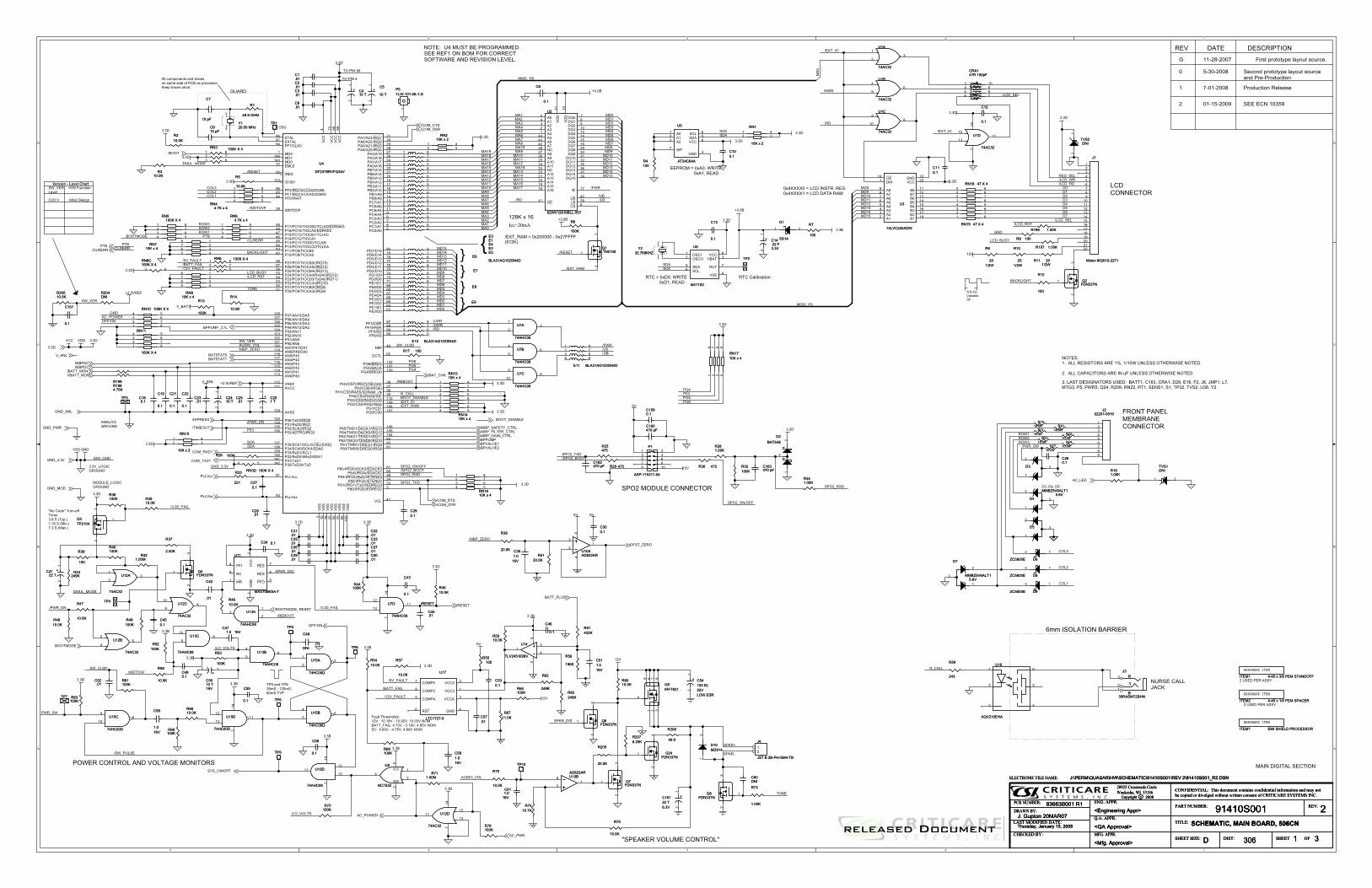
�
�
�
�
�
�
�
�
�
�
� �
� �
��� � ��
������
�����
����
��
��
��
����
����
� ��
�
��
��
� �����������
������ �
������������
������
�� �
�� �
�� �
������������������
���������
������ ��
����
���
��������
����
����
���
���
��
��
��
���
���
��
�
���
��
���
���
���
��
��
���
��
����
�!��
���
���
�"�##��$
������
���
��
��
��
���
���
��
���
��
���
����
��
������
���
��
����
���
���
���
���
����
��������
��
����
���
���
���
����
����
���
���
����
����
����
����
���
���
����
���
���
������
���
���
��
����
� �����
������ �
��#�����
������
�������
������%�
��� �����
��#�����
�����&
������� �
������%�
������� �
�������
��%����
�� ��!�
��%����
���
������&
�� �
��%���� �����'
������
�� ��� �
������&����
������&����
���������
�� ����
������
&��
������%�
�����
�����
��
�� ��!�
��&�
������
�������
������
� ���� ��
� ���� ��
������
����(
�������
������&
������� �
������
��������
��������
��"�##��$
�!�����
&���)���
� �����
�&�
���������
��� �����
�������
���� ��
�� ������
���������
&���)���
�&�
� ������
��&�
&��
�&���#��
���
��
���� ��
� ������
�����'
������
������
��%����
���
��%����
��
������
�����&�
� �����
����*
������%�
��
��
��
��
��
��
��
��
��
��
��
��
��
�� ��
��
��
��
��
��
��
��
��
��
��
��
��
��
��
��
��
��
��
��
��
��
��
��
��
��
��
��
��
��
��
��
��
��
��
��
��
��
��
(�#�
(�#�
�� ��
�#��
��&
(�#�
�#��
�#��
�#��#�
���
�#�
�#��
�#��
�#��
�#��
�#��
�#�
�#��
�#���#��
���
�#��
���
�#��
�#��
��
�#��
�#��
�#��
�#��
��
���
�#��
�#�
�#�
�#�
�#�
�#��
�#��
���
�#��
�#��
�#�
��
��
��
��
��
�&�
��� �#�����
��
(�#�����
��
�#�
��
�#��
����
��
�&��&
�&�����
������&������&
�����
�&���#��
����
�������
��������
�����
��������
��������������
���� ��
����������������
�����&
������� �
�'���&����
����!�
�����%��
�����%��
� �++
� �,,
��������
&�������'���� &����� ������� &�����&���� ������� ����� ���
�� ������
�!������
��������
�����)���
(�#�����
�� ��
�����
&���&����
�������
�&�����
��&
�#��
������
������������� ���������������������� �������� �!"#�� � ����$�%&��%&� %��%' ��%& ��� %'�$�& %��%��$�(�%&
)���* ������ +��,���- &��&�-� &&�%��%�%&�'��.� ��!.��/0/ �1/����2
�.!���30#
"!/ �1���������! �#
�4��5���30#
��62�!77.2
82!2�!77.2
1�62�!77.2
7!. ��913�.# .�:2
� "�#
/4�� �/�;�# ��/ # /4�� ��
�"�� .�������"���!1�#
7�3��913�.#��-./012345555555
�������������� ����������
���������
678����89���8!�8��!�����8���������8���5�8������������#��&
� �
6#5�:.4-;5������
��� �
�������5�����
<95..0-=>?@
<�A2#5..0-=>?@
<�;21;BB01;25..0@
�3:0,C>/D56>;:>0/5��D5����
��%����5E5�F������5*5�F������G����H
�� �5F5�����<��$!
���5�>?1I0>41-;
����
���� �� ��������&�
& ������&�
�#��� ��������&�
��5��&5�
��5��&5�
����&&�����
�����5��&��� 5&�5�� ���5��&�����
�F�%%%%�5E5 ��5�&���#5����F�%%%%�5E5 ��5��5��
������5E5�F�D5�����5555555555555555555�F�D5���
���5E5�F��D5�����55555555555�F��D5���
���&�5�&� ����&���&&�����
����5���� �5��&&�����
�#5 ��5�����&����5����755���D5����D5���D5���D5���D5��D56�D56���D5 �D5����D5��D5����D59��D5����D5�&��D5���D5��&��D5��D5����D5����D5�� D5'�
&����7�#55 5���������5��5�JD5�����5�& ���5��!������5&����#
�#55 5��������5��5�&5:�5�& ���5��!������5&����#
��&5����� 5������&
��� ��� ����������&
K������5�� ���5��&��� K
K&-5�-CBK5�:0;*-AA�1LB0�# 5�5G�/.#H�#��5�5G�1;#H�#�5�5G�>F#H
���5>;C5�� 75��L�5*5���L�D �L�5�'�
��D5��D5��
&���755��5����5�5���������#55���5����5�&5��5���5�������5�������5&�5�������&5 ��� #
�5����5���5��'
�>:?45�30B,3-?C,7���755��#� �5*5��#���D5��#���5&������� 75�#���5*5�#� �D5�#���5&����755�#���5*5�#���D5�#� �5&��
���5!M�>01>I?B5��
�LL5��� ���&5�����
&����5� 6��
??5+-L.-;B;4,5>;C540>+B,-;5,>LB5,1CB5-A5��5>,5.0-+B,,-0�BB.540>+B,5,3-04#
���
NNNN
N
������������������ �!������ B=B?
!��5�:;+41-;
�#��5� �;141>?5�B,12;
� ��*� *���� �10,45.0-4-4/.B5?>/-:45,-:0+B#
�
�5����5���5��'
�*��*���
� �*��*��� �0-C:+41-;5�B?B>,B
�B+-;C5.0-4-4/.B5?>/-:45,-:0+B>;C5�0B*�0-C:+41-;
���5��&5�������*��*�����
���
���
���
���
��������������
�� �#����
�� �#����
���� #������� #���
��������������
�����&������&�
��
��������������
��
�����
��
�����
�
��
��������� �*��5F5���5���5����������
��������� �*��5F5���5���5����������
���
�����
���
�����
��
����
���
���
���
���
���
��������������
#�����#�����
9���&���&9���&���&
�
�
�
����#� ���
����#� ���
�#�����#����
��������������
���
��!��
���
��!��
��
����
���
����
���� �
��
�����#�������#��
����
��!��
����
��!��
�
��
����
��!��
����
��!��
��
����
���
��������������
����
�����
����
�����
�
��
���� ������� ���
�
��
����#�������#���
6�
�-?BF5O�����*����
6�
�-?BF5O�����*����
������� ������������������ ��������
���
����
���
����
������
������5���.�������5���.�
����
�
�
��
���#�����#��
��
��!��
��
��!��
�
��
������
�� ��#���� ��#��
�����#�������#��
#�����#�����
���#�����#��
��
��!��
��
��!��
�
��
(��
��5�(
��
��5�
����
��5.�
��
��5.�
����
���� �
��
����������
����
��
�������&��
��
�������&��
���� �
��
�&��
���5F5�
�&��
���5F5�
��
��
���
����
���
����
���
��#��
���
��#��
9���&���&9���&���&
�
�
�
�#�
���
�#�
���
����#����
��#��
#����#����
�&����5F5��&�
���5F5�
����
���
�����#��
�����#��
�� #���� #��
����
���� �
��
���
�#���
���
�#���
�#�����#����
���
����
���
����
���
������*�
���
������*�
���� �
���� �
��� �
�&� �
������
�����
�����
����
��
��)��� ���#��
��
��)��� ���#���
�
�
������
������
��
������ �� *���
��
������ �� *���
�������������������&�� �������������&���������������
�� �����
� ��
�9� ��9� �9� ��9� ���9� ���9� ���9� ���9� ��
���
��
�������
�9 ���9� ���9�� ���9�� ���9�� ���9�� ���9�� ���9�� �
���
��
� �� ��
��
��)��� ���#��
��
��)��� ���#��
�
�
�
9��&����9��&����
�
�
�
�#�����#����
��
#���&�
��
#���&�
'���#��5�!M'���#��5�!M
������
���
��!��
���
��!��
�
��
���
��#��
���
��#��
�#�����#����
�����#�������#��
���
��#��
���
��#��
6������*����
6������*����
������� �
#�����#�����
#�����#�����
��
��*������*��
��
��*������*��
� �� �� �� � ��
(������5��#��
(������5��#��
��
���
�#�
���
�#�
���#�����#��
��������������
���
�����
���
�����
�
��
���
�#�
���
�#�
�#�����#����
��
����
��
����
��
�� �#����� �#���
���
��!����
���
��!����
�
��
�������5.��������5.�
�#�����#����
���
��#��
���
��#��
�����#��
�����#��
���
#��
���
#��
��� ������ ���
����������
��
������
��
������
����#����
����#����
��
�#�
��
�#�
���
�#���
���
�#���
�#���� �#����
� ���� ���
�������5.��������5.�
������������
����#����
����#����
#�����#�����
���
�#�
���
�#�
���
��!����
���
��!����
�
��
�����#��
�����#��
��������������
���
����
���
����
��
��#��
��
��#��
���� �#������� �#���
(�����5�
(�����5�
��
�&��&�
� �
�����#�������#��
��� ������ ���
����
��!����
����
��!����
��
����
���
��� �#������ �#���
9���&���&9���&���&
�
�
���������
#��� #���
�& �����5%5��& �����5%5�� �
�����#��
�����#��
�&�� ����5%5��&�� ����5%5�
����
���
�����#�����
��#��
������
�����#�������#��
������
��� �������&����� �������&��
���� �
��
��)�� ��� ��)�� ���
��
���
���
���
���
���#�����#��
��
�� �������
��
�� �������
�� �� �� �� �� �� � �
���� ����
� � � ��� ��� ��� ��� ��� �� ��
��� ���&� ��
��������������
���
��!��
���
��!��
�
��
�&�
���5F5�
�&�
���5F5�
��
��
9����� ��9����� ��
� �
�
� � �
�
#�����#�����
�&��#��5F5�
�&��#��5F5�
����
���
#����#����
��������������
�&�����5F5��&�����5F5�
����
���
�����#������#�
��� ������
��� ������
���
� ��������
���
� ��������
�
��
��
����
�
�
�
������
����#����
����#����
9 ��&���&
9 ��&���&
�
�
�
���
��!��
���
��!��
�
��
����
��!����
����
��!����
�
��
6�
6��55�*�!*���*�
6�
6��55�*�!*���*�
��
�����&������&�
���
�����
���
�����
�
��
���� ������� ���
�
��
�
��������������
��������� ���5�!�� �5�������������P
��������� ���5�!�� �5�������������P
�����#�������#��
����5.�����5.�
�&�����5F5��&�����5F5�
����
���
� �
�������� �
��
��������������
� �
�&��#��5F5�
�&��#��5F5�
����
���
( ����5�
( ����5�
��
�#�����#����
��
��#��
��
��#��
����
�
�
�
( ���#��5��#��
( ���#��5��#��
��
����&�����&�
�#�����#����
��
������
��
������
��� �� ������
�����
����� �
��� �
��� �
�����#��
�����#��
��������
����
�����
����
�����
��
����
���
�� ������ ����
�&�� ��5%5��&�� ��5%5�
����
���
�����#�������#��
�� ��
��������������
�����#��
�����#��
����#������#��
�����&������&�
��
�� �#����� �#���
�#�
���
�#�
���
�&��
����5%5�
�&��
����5%5�
����
���
� )�� ��� � )�� ���
��
������
������ �
�
�
�&����5F5��&�
���5F5�
����
���
9����&���&9��
��&���&
�
�
�
�� �#��� �#�
#�����#�����
( ����5�
( ����5�
��
����
�#�
����
�#�
#�����#�����
� � ���� �
��
�#�
��
�#�
��
�
�
6�
�������!&
�
�
6�
�������!&
�
��
#�����#�����
9���&���&9���&���&
�
�
�
����5%5�����5%5��
� �
��
����� ���9���
��
����� ���9���
���
�����
�
%� ���%� ������� ����
����������������
������
���'���
������� � ������9��������9�� �
&�� ��
����������� ��G��H�Q���N����������������������
���
�
���
�
���
�����
��
���
��
���
������� �������� �����!�� ���� �� �
������9��� ����9� �
����� ������ ������� ������� ������� ������� ������� ������� ������� ������� ������ ����� ������� ������� ������� ������� ������ ����� ������ ������ �
������� �������� ��������� � ������� ��������� ��������� �������� ������� �������� �������� �������� � ������ �������� �������� �������� �������� ��
�����F����� ���������F����0�F�������������F����������F����0�F����
�!������G��9�H ���!������G��9�H������� �
��������������G��9��H� ��������������G��9��H����������������G��9��H�����������������F���G��9��H������������������F���G��9��H��
��������������G��9�H��
������ �������� ��������������� ������������������ ��� ����������������� ��� ���������������� ����������������� ���� ��������������������� ����������������� ����������
&�����������&�����������&������� &��������&��������&��������&��������&��������
������
������
�������
��������9� � ��������9� ����������9� ����������9� ��
���
���
�!������������ ���!���������������+?R ��
��������������G��9 H��
���
��
���
�
�����F�����9���������F�����9����
�����������9����
������� ���
������9� ���
�������������� ����������������� ���
������� ��
�����������9����
���������������G��9��H��
���
��
� �++��
� �,,���� ��
�� ���
��� ��
����& ��� ����&���� ����&����� ����&����� ����&�������� ����&�������� ����&�������� ����&�������
������ ���������9 ���
�������������9����9 ��������������9����9� �������������&�����9�� �������������&�����9�� �������������������9�� �������������������9�� ���
� ��G��9�H�����9� �� ��G��9�H��F�������9� ��� ��G��9�H����&�� ��� ��G��9�H��F������&�� ��� ��G��9�H������ ��� ��G��9�H����������� ��
��������
�&�����5F5��&�����5F5�
� � � �
� � �
������#��������#��
����#���
����#���
������
�#�����#����
�&� ��5%5��&� ��5%5�
����
���
��
��#��
��
��#��
���
��#�
���
��#�
�&�����5F5��&�����5F5�
����
���
��� ������ ���
��� �������&����� �������&��
���� �
��
����������������
��
��
������
��
������
������
���
�� ��� ����
�&� �
���� �#������� �#���
�#�
���
�#�
���
������
��������� �*��5F5�� 5���5��&���������
��������� �*��5F5�� 5���5��&���������
(
�����5����
(
�����5����
��
��������������
�����#�������#��
���
�%�� ��*�
���
�%�� ��*�
���
�
����
&��
��� ��� �
���
��� �
�&�
�
��
��#�5�!�
��
��#�5�!�
( ������5� ��� ��5���
( ������5� ��� ��5���
��
���
���
���
���
����#���
����#���
��
����
��
����
�������5.��������5.�
�&����5F5��&�
���5F5���
��
��
���
��
���
���
���
�
&�����
���
���
�
&�����
�
��
��
�����#��
�����#��
����
��#��
����
��#��
#����#����
�������� �
��
��� �*���*��*�*���� �*���*��*�*�
�
��
�����
��
�����
�
��
���
��#��
���
��#��
���
�#����
���
�#����
�&�����5%5�
�&�����5%5�
����
���
����
���� �
��
����
���� �
��
��� ������� ����
( �����5�
( �����5�
��
�#�
���
�#�
���
'���#�� �!)'�
��#�� �!)
9�������9�������
�
�
�
�&�� ����5%5��&�� ����5%5�
� �
�& ����5%5��& ����5%5��
��)�� ��� ��)�� ���
��
�����#��
�����#��
���
9�����!
���
9�����!
�
�
�
�
�
�
���
�����
���
�����
�
��
���
������
���
������
�#�
���
�#�
���
released Document
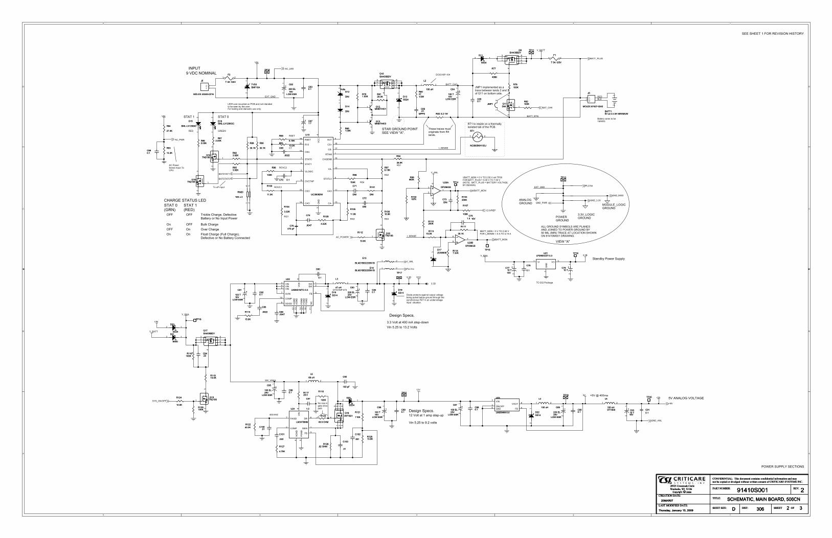
�
�
�
�
�
�
�
�
�
�
� �
� �
����!�
������
����&��
�%���&�
����&��
�����&
�%���&�
��
��
��&
����
���
�#��
��&
��&
����
��&
�#�����
���
����
��(�
(�#�����
�'���&����
�������
����!�
�����
�����
�����
� �++
��&
�&���#��
������&
������&
�� ��
�&�����
� �,,
���� ��
�&��&
�&�����
(�
�#��
�.�! �����! �#
"!/ �1���������! �#
7!. ��913�.# .�:2
� "�#
/4�� �/�;�# /4�� ����/ #
������������� �����������������������-./012345555555+
�������� �!"#�� � ����$�%&��%&� %��%' ��%& ��� %'�$�& %��%��$�(%&�)���* ������ +��,���- &��&�-� &&�%��%�%&�'��.� ��!.��/0/ �1/����2
���!�����D5��&5���D5����&
���������
�3:0,C>/D56>;:>0/5��D5���� � �����
������
��� �.�! �����! �#
"!/ �1���������! �#
7!. ��913�.# .�:2
� "�#
/4�� �/�;�# /4�� ����/ #
������������� �����������������������-./012345555555+
�������� �!"#�� � ����$�%&��%&� %��%' ��%& ��� %'�$�& %��%��$�(%&�)���* ������ +��,���- &��&�-� &&�%��%�%&�'��.� ��!.��/0/ �1/����2
���!�����D5��&5���D5����&
���������
�3:0,C>/D56>;:>0/5��D5���� � �����
������
���
���
���
���������
�����
�����
���
����
��
�-5:�51;.:4
�������*���
�-054B,41;25>;C5C1>;-,41+5:,B5-;?/#
�5���5&���& �&���
���5����5�
��� ����&
�!���5�����5 �����5�G��&H
���5�G���H
��� ��� �01+R?B5�3>02BD5�BAB+41=B>44B0/5-05&-5�;.:45�-SB0
��� �;:?R5�3>02B����;�=B05�3>02B
�; �; �?->45�3>02B5G�:??5�3>02BHD5�BAB+41=B5-05&-5>44B0/5�-;;B+4BC
��T,5>0B5L-:;4BC5-;5��5>;C5;-451;4B;CBC4-5IB5,BB;5I/543B5:,B0#
��5�-?45>45�5>L.5,4B.*:.
�1;5�#��54-5�#�5=-?4,
���5�!)5
�B,12;5�.B+,#
�#�5�-?45>45���5L5,4B.*C-S;
�1-CB5.0-4B+4,5>2>1;,45-:4.:45=-?4>2BIB1;25.:??BC5IB?-S520-:;C5430-:23543B,/;+30-;-:,5���51;5>;5:;CB0=-?4>2B1;.:455,14:>41-;#
�������*���
�1;5�#��54-5��#�5�-?4,
��5���5�>+R>2B
�4>;CI/5�-SB05�:..?/
�5�-SB0�B;,B5�;.:45�-���5
�B,12;5�.B+,#
���5����&�5���&����5����5KK#
���������&�
�#��� ��������&�
5����&�5�'�� �5��5� &��&�56��&��5��5�����5����&�5'��5�� 5G��&H5����5�5 �����&5�!��&�&5���������5����&�#
����5KK
����
>44B0/5S10B,54-5IB� ��5
������&5E5�5�5��5�#��5�5S045�������5���� ��5E5�#��5�5��5�#��5�G&���755���� ��5E5����'5�� ���'5�����&H
�3B,B540>+B,5L:,4-0121;>4B5A0-L5��?>;C,#
������&5E5�5�5��5�#��5����5����&��5E5�55��5�#��5
�����5���� '5������&�
���� �� ��������&�
���5�!���5�5���5�������&5!�����'
&-5=1>,51;2>4B5C01=B.>43
(��5U5���L>��5& ��5�� ���
& ������&�
���54-50B,1CB5-;5>543B0L>??/1,-?>4BC54>I5-A543B5��#
6���51L.?BLB;4BC5>,5>540>+B5IB4SBB;5?>;C,5�5>;C5�-A59��5-;5I-44-L5,1CB#
(�����5����
(�����5����
��
������#��������#��
( ����5�
( ����5�
��
����������������
������������������
��
����
#���
����
#���
��
�5�5����
��
�5�5����
� �
��������
���
� #��
���
� #��
��� ���
9���������9���������
�
��
� ���#��� ���#��
����#�������#���
�
���5:!�����
�
���5:!�����
� �
� �#�� �#�
�� 5:! �
� 5:!� �
(���
���5����
��5���
(���
���5����
��5���
��
���
����
���
������������
��
�#�
��
�#�
�����#��������#���
�
���5:!
�
���5:!
� �
���
����
���
����
� �
���
��������*�#�
���
��������*�#�
��&���&���&�
�� ��� ��
�
�
��&�
������
����� �&�
���&�
��
��&�
����&�
����&�
��
� �
&�
��
����#�����#�
����
�#���
����
�#���
����
����
����
����
9���������'9���������'
��
�
���
�
��������
����������������
�
�#���
�
�#���
���
����
���
����
��������������
��
��������
����#�����#�
(��
���5����
��5���
(��
���5����
��5���
��
����#�������#���
�#�����#����
���
�&�
���
�&�
� ������ �����
���
#����
���
#����
����
�#���
����
�#���
9���������'9���������'
��
�
���
�
����
��#��
����
��#��
��� ��������&�
��� ��������&�
��
��������������
����
�&�
����
�&�
� ��#���� �
�#���
6���6���
��
����
��#��
����
��#��
� �
��#��
� �
��#��
�����#��
�����#��
���
�#�
���
�#�
����
��#��
����
��#��
��������
��� #��5�!�
��� #��5�!�
���#��
����
���#��
����
��
�5�5����
��
�5�5����
� �
(���
���5� ���
��5���
(���
���5� ���
��5���
��
���
����
���
����
����&�����&�
���
�&�
���
�&�
��
������#��������#��
9���&����9���&����
�
�
�
��������������
��
���
#����
���
#����
��������
���
�&�
���
�&�
� �
#����
� �
#����
����� * %����������� * %������
��
��������
�
���5:!
�
���5:!
� �
� �
��#��
� �
��#��
���
���
���
���
� �
����
��#��
����
��#��
���
�������
���
��������
��
�����
� ������� ��
9���&�9���&�
�
�
�
� �
�#�
� �
�#�
���
����
���
����
� �
����
��#��
����
��#��
����������������
�&��
���5F5�
�&��
���5F5�
� �� �
� �������
� �������
����
��#�5�!�
����
��#�5�!�
����#�����#�
���
���� ��
���
���� ��
��&
�� �
��&�
�
�&�
�
���& �
� �
�����
�����
(� �
���5� ���
��5���
(� �
���5� ���
��5���
��
9���������9���������
�
��
���
��#��
���
��#��
9���&����9���&����
�
�
�
�� �#��� �#�
��������9��������'
9��������'
��
�
���
�
������#�������#�
���
��������&�
���
��������&���
� ��#���� ��#���
���)�� ������)�� ���
��
(� �
���5� ���
��5���
(� �
���5� ���
��5���
��
���
���5.�
���
���5.�
����#� ������
�#� ���
������#��������#��
� ��#�� ��#�
����#�����#�
����
�#���
����
�#���
6�
�� �%5 ����*����
6�
�� �%5 ����*����
��
� ��#�� ��#�
��� �#���� �#�
6�
�� �%5�����*����
6�
�� �%5�����*����
��
��������
����
����
����
����
�
���
&�� ���!���6
�
���
&�� ���!���6
� �
�� ������ ����
��
�������������
�������
�
��
��� ��������*�#�
��� ��������*�#�
���
�&�
�
�� �
9���&����
9���&����
�
�
�
���
����
���
����
� �
���
��������
���
��������
��� �
��* ��
��( ��
��!� �
� �����
���
�
�!��& ��
�* ��
��� �
�� ��
�&�
�
�* ��
�����
����
�����
�����
�����
������
�����
�����
������#������
��#��
����
#��
����
#��
����#�������#���
� �#����� �#����
(���
���5� ���
��5���
(���
���5� ���
��5���
��
������#��������#��
���#�����#��
�
��5:!
�
��5:!
� �
����#��
����#��
� � �#�5��� � �#�5��
�� ������ ����
��������
���
�� * %������
���
�� * %������
��
���
������*�#�
���
������*�#�
��&�
�&��
����
� ��&�����
��
����
��
����
���5.����
���5.����
(�����5�
(�����5�
��
����
#���
����
#���
����
��#��
����
��#��
(� �
���5����
��5���
(� �
���5����
��5���
��
( �����5����
( �����5����
��
����-?4,
�&�
����-?4,
�&�
��
���
��#��
���
��#��
��������������
�����
�#�����#�9�
���� ��9� ���� ��
� �
�
� � �
�
9���&����
9���&����
�
�
�
� ��#���� ��#���
����������������
(� �
���5� ���
��5���
(� �
���5� ���
��5���
��
����#�������#���
�����5>45�#�5!5��&���������5>45�#�5!5��&����
��
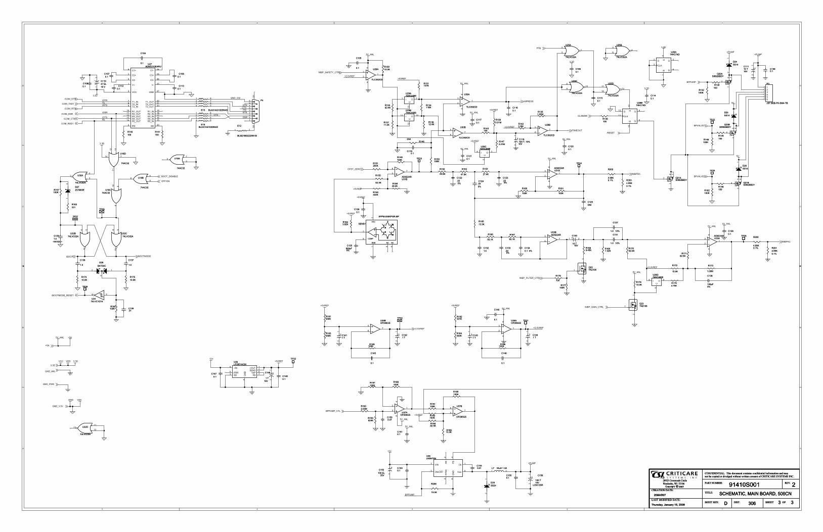
�
�
�
�
�
�
�
�
�
�
� �
� �
���
�F
������
���
�������
����
���
�F
�&�����
����
����
�����
(�#�����(�����
(�#�����
(�#�����
(�#�����
��
��
��
����
��
��
��
��
��
��
���&
(�����
(����
���&
���
(�����
(�����
(�����
���&
���& ���&
���&
(��������&
(�����
(�����
���&
���&
���&
���&
�#��
���&
�#��
�#��
��
��
(����(����
��� �#�����
�#��
��
��
��
��
��
��
���& (�
(�����
���
���
(�����
��
��
��
��
�&�
��
�#�
&����� �������
(�
�&��&
�#��
�� ���
�����
&�������'����
������
�&�����
(�#�����
�!������
�� ����
��������
��������
�����%��
�&���#��
�����)���
������� �
�����&
&����
��������
&�����&����
&���
�����%��
��������
��������
��������������
���� �������
��
��������
�� ���
�.�! �����! �#
"!/ �1���������! �#
7!. ��913�.# .�:2
� "�#
/4�� �/�;�# /4�� ����/ #
������������� �����������������������-./012345555555+
�������� �!"#�� � ����$�%&��%&� %��%' ��%& ��� %'�$�& %��%��$�(%&�)���* ������ +��,���- &��&�-� &&�%��%�%&�'��.� ��!.��/0/ �1/����2
���!�����D5��&5���D5����&
���������
�3:0,C>/D56>;:>0/5��D5���� � �����
������
�����.�! �����! �#
"!/ �1���������! �#
7!. ��913�.# .�:2
� "�#
/4�� �/�;�# /4�� ����/ #
������������� �����������������������-./012345555555+
�������� �!"#�� � ����$�%&��%&� %��%' ��%& ��� %'�$�& %��%��$�(%&�)���* ������ +��,���- &��&�-� &&�%��%�%&�'��.� ��!.��/0/ �1/����2
���!�����D5��&5���D5����&
���������
�3:0,C>/D56>;:>0/5��D5���� � �����
������
����
��������
����
��#��
����
��#��
��������������
�� ������� �����
�� ������� �����
�#�55�J�����#�55�J����
�#�
����
�#�
����
�#������#�����
����������������
9���������'
9���������' �
�
�
��
�����
��
�����
�
��
��� ���������� �������
(�&
������� �
&�
�
(��� ���&� ��� �� �
�#������#�����
�� ������� �����
#������
�J#������
�J
����������������
���
� ������
���
� ������
�
��
�#������#�
����
�#�
����
�#�
����
��� ���
����������������
����
��#��
����
��#��
�����!���������!����
��
� ��
9 �
9 �
��
��
��������
�����#����#�J
�����#����#�J����
�#������
�#��
�� �������� ������
��&�
�&�
�
�,S
�I �
�&�����
��
�'&�
���
�
����#���J
����#���J
(������5����
(������5����
��
�� ������� �����
(�����5�
(�����5�
��
���������������
���������
��(� ��* ��
��(�
��*�
��( �
��* ��
�(�
����
�* ��
�&� ��
������ �������� �������� ��
����& ������& � ����& ������& ������& ��
����&�����& ����&�
����������������������������������������
�&� �� ��
�#������#�����
����
���
����
���
��������������������
�
��
�
����
�#�
����
�#�
����
����
����
����
�����&�
�����&�
��������������
#������
�J#������
�J
�&������&�����
���.�
���
�J���.�
���
�J
(�����5�
(�����5�
��
�� ������� �����
������#��������#��
������!�����������!�����
� � �
��
��� ������� ����
�����#��������#���
��������������
��� ��#����� ��#��
��� #������ #���
����
��#��
����
��#��
���
�� ����
���
�� ����
�
��
����
�#����#�J
����
�#����#�J
�#�������#������
����
��#��
����
��#��
9���&����9���&����
�
�
�
��������������
���
� ������
���
� ������
�
��
�
( �����5�
( �����5�
��
�#�
����
�#�
����
�� ������� �����
�#�����
�#�����
�����#��������#���
��������������
�#�
����
��J�#�
����
��J
����
��#��
����
��#��
9���&����9���&����
�
�
�
�#������#�����
����������������
����#������#��
( �����5�
( �����5�
��
�� ������� �����
�� ������
�� ������
���
�������������
�������
�
��
�
��������
���� ������� ����
��
����
����
����
����
�����#��������#���
����������������
��������
����������������
�����#����#�J
�����#����#�J
��������������
���
��������&�
���
��������&�
��
�#������#�����
����� ����������� ������
��
�#�
����
�#�
����
#������
�J#������
�J
9���������'9���������'
��
�
��
6��5�*�!*���*�
��
6��5�*�!*���*�
������
��������������������
�
��
(
������5� ��5�
(
������5� ��5��
�
������#��������#��
���� �#������ �#��
� �.�����
�J� �.�����
�J
��
� ������
��
� ������
�
��
�
����������������
����
�� ����
����
�� ����
��
����
��������
������#��������#��
���� ������� ���
�
��
(
����
��5����
(
����
��5����
� �
�#������#�
����
9���������'9���������'
� ��
�
�#������#�����
�#������#�����
��������������
��
������#��������#��
����������������
�#���� �#����
���
�� ����
���
�� ����
�
��
�����#��������#���
����
��#��
����
��#��&�&��&�
����
�����&��
%���*�������*�
&�&��&�
����
�����&��
%���*�������*���
�
�
��
9���������'
9���������' � �
�
�
�����#��������#���
�#������#�����
��������
�#������#�����
������#��������#��
���)�� ������)�� ���
��
����
�#�
����
�#�
��� ������� ����
��������������
����������������
������ ������� �
����
�#���
����
�#���
������#��������#��
�#������#�����
��������
��������
�� ������� �����
��������������
��
��������
����������������
��
� ������
��
� ������
�
��
� ��:!5�#� � ��:!5�#�� �
����
��#��
����
��#��
���� ������� ���
�
��
�
������#��������#��
����� �������
�� ����
���
�����#�<����@
�����#�<����@
������� �����
��
��
�#���� �#����
�� ������ ����
�����#��������#���
�����#��������#���
�#������#�����
����������������
�����!����������!�����
�� � �
���
��������������
��
����
�� ����
����
�� ����
��
����
�#�
����
��J�#�
����
��J
(����
�5����
(����
�5����
��
�#������#�����
���
�������
���
�������
�
��
����
�#����#�J
����
�#����#�J
������!�����������!�����
�� � �
��
��� ��#����� ��#��
( ��� ���5�D5��J���
( ��� ���5�D5��J���
��
(�������5� ���
(�������5� ���
��
���� �#������ �#��
���
�� ����
���
�� ����
�
��
�#�
����
�#�
����
������ ���������� ����
���
��
�����
��
�����
�
��
��� �������&�����
�������&��
���� �
��
�#������#�����
������#��������#��
�#������#�����
�#�������#������
��� �#���� �#�
��������
��������������
��
�� ������� �����
��������������
�����!����������!�����
��� � ��
���
(����
���5����
��5���
(����
���5����
��5���
��
�#������#�����
����
�� ����
����
�� ����
���
���� ������� ���
�
��
�
�����#��������#���
�� �
�����
�� �
�����
�� ����
�� �
��� �������&����� �������&��
���� �
��
�� ������
����
� �
�
�#���� �#����
�����!���������!����
���
� ���
9 �
9
���
���
����
��#��
����
��#��