1 introduction - unina.it
TRANSCRIPT

1 Introduction
The under development SiDMACIB plugin intends to design the structurally-sound masonry
interlocking units with non-isotropic sliding behaviour. Interlocking units are rigid blocks which, on
their faces, have a number of locks keeping the blocks together and preventing sliding.
This version of SiDMACIB plugin enables the designers to model a single layer assemblage composed
of conventional or interlocking blocks and analyse their structural feasibility. The implemented
structural analysis is a concave contact model within the limit state framework developed for corrugated
interfaces having locks with rectangular cross section. Sliding of such interfaces is constrained by the
Coulomb’s friction law and by the shear resistance of the locks along two orthogonal directions.
In this manual, the proposed design process is first introduced. Then all the developed GH components
for this process are presented.
2 Installing SiDMACIB plugin for grasshopper
Opening Grasshopper within the Rhinoceros 3D, Grasshopper Assembly File “Sidmacib.gha” should
be saved in the folder shown in Figure 1.
Figure 1. Installing the plugin
3 Design process
The design process including the modelling and analysis phases is outlined in Figure 2.
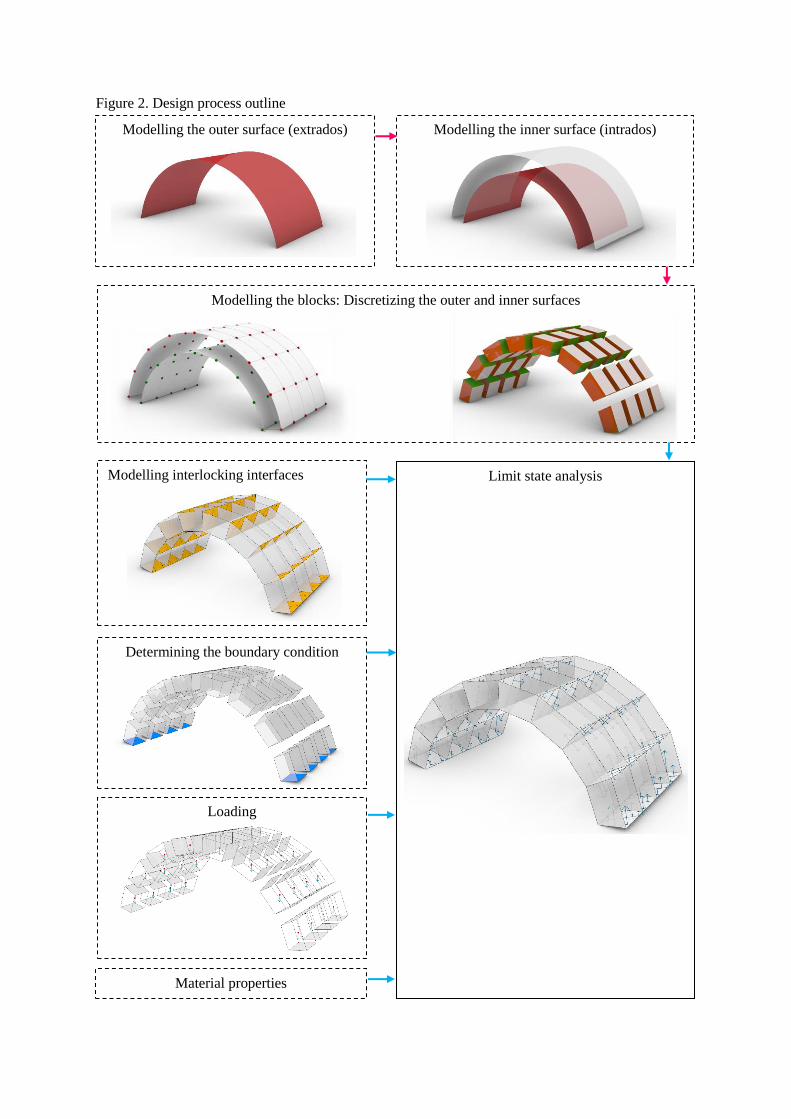
Figure 2. Design process outline
Modelling interlocking interfaces
Determining the boundary condition
Limit state analysis
Modelling the blocks: Discretizing the outer and inner surfaces
Modelling the outer surface (extrados)
Modelling the inner surface (intrados)
Loading
Material properties

4 Modelling Phase
4.1 Outer surface
The outer surface can have an arbitrary shape. Representing the surface grids by U and V axes, �⃗� ⨂𝑣 must be outwards. The surface can be closed along v direction (Figure 3) and also be converged towards
the surface apex and be closed along u direction (Figure 3).
Figure 3. The plug-in provided also several GH components to model the overall surface with various
geometries:
Component Description
Circular Arch component (CArch)
Input
Base Point (BPt) Mid-point of arch base line
Extrusion Direction (ED) the direction of the arch extrusion
Radius (R) Radius of arch
Height (H) Distance between apex and base point of arch
Depth (D) Depth of arch
Output
Circular Arch (CA)

Component Description
Freeform Shell (FSh) Construct a freeform shell by a set of curves
Input
Curves (Cs) Curves on shell
Output
Freeform Shell (FS)
Component Description
Oval Arch (OArch)
Input
Base Point (BPt) Mid-point of arch base line
Extrusion Direction (ED) The direction of the arch extrusion
Horizontal Radius (HR) Horizontal radius of arch
Vertical Radius (VR) Vertical radius of arch
Height (H) Distance between apex and base point of arch
Depth (D) Depth of arch
Output
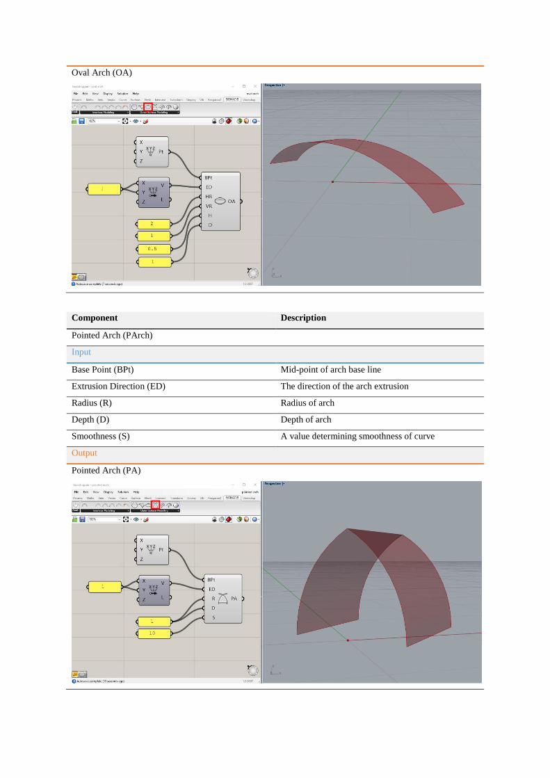
Oval Arch (OA)
Component Description
Pointed Arch (PArch)
Input
Base Point (BPt) Mid-point of arch base line
Extrusion Direction (ED) The direction of the arch extrusion
Radius (R) Radius of arch
Depth (D) Depth of arch
Smoothness (S) A value determining smoothness of curve
Output
Pointed Arch (PA)
Component Description
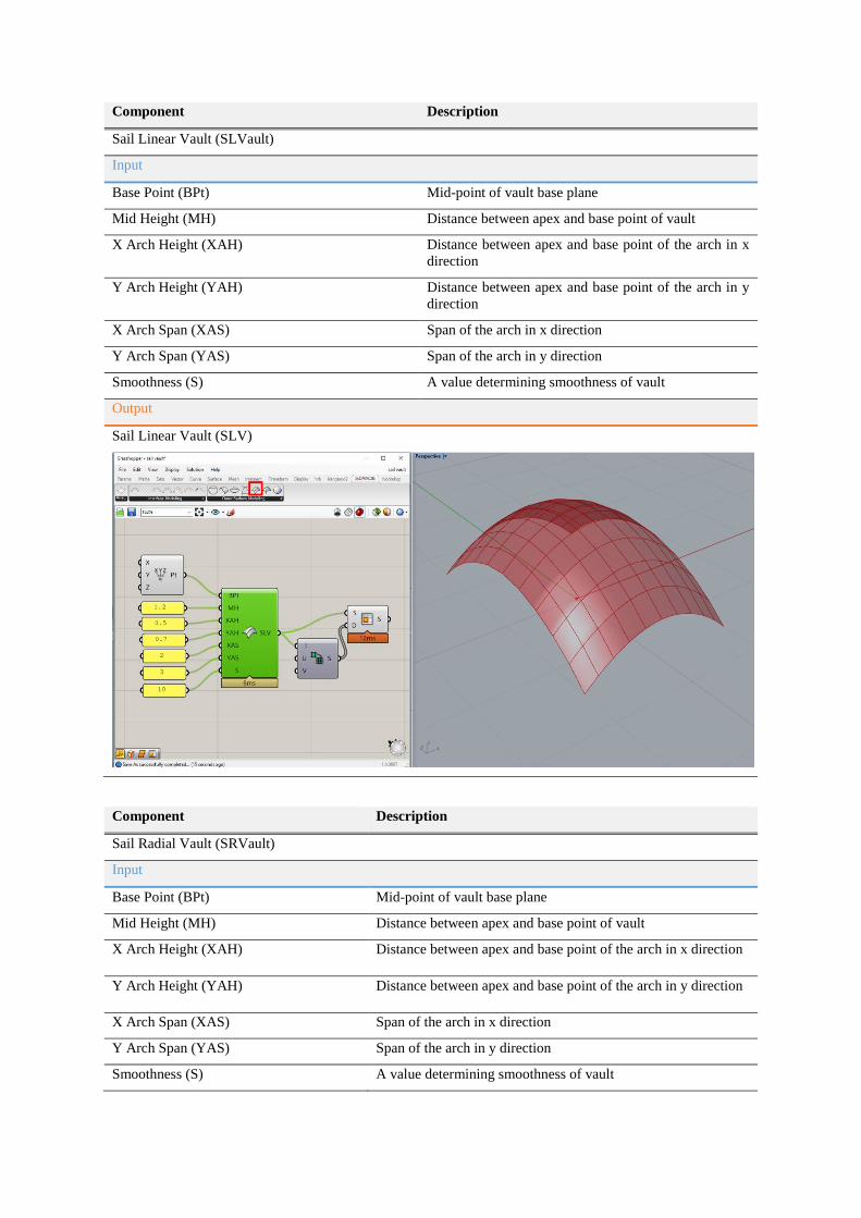
Sail Linear Vault (SLVault)
Input
Base Point (BPt) Mid-point of vault base plane
Mid Height (MH) Distance between apex and base point of vault
X Arch Height (XAH) Distance between apex and base point of the arch in x
direction
Y Arch Height (YAH) Distance between apex and base point of the arch in y
direction
X Arch Span (XAS) Span of the arch in x direction
Y Arch Span (YAS) Span of the arch in y direction
Smoothness (S) A value determining smoothness of vault
Output
Sail Linear Vault (SLV)
Component Description
Sail Radial Vault (SRVault)
Input
Base Point (BPt) Mid-point of vault base plane
Mid Height (MH) Distance between apex and base point of vault
X Arch Height (XAH) Distance between apex and base point of the arch in x direction
Y Arch Height (YAH) Distance between apex and base point of the arch in y direction
X Arch Span (XAS) Span of the arch in x direction
Y Arch Span (YAS) Span of the arch in y direction
Smoothness (S) A value determining smoothness of vault
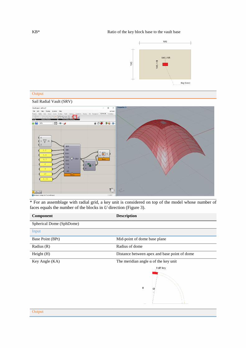
KB* Ratio of the key block base to the vault base
Output
Sail Radial Vault (SRV)
* For an assemblage with radial grid, a key unit is considered on top of the model whose number of
faces equals the number of the blocks in U direction (Figure 3).
Component Description
Spherical Dome (SphDome)
Input
Base Point (BPt) Mid-point of dome base plane
Radius (R) Radius of dome
Height (H) Distance between apex and base point of dome
Key Angle (KA) The meridian angle α of the key unit
Output
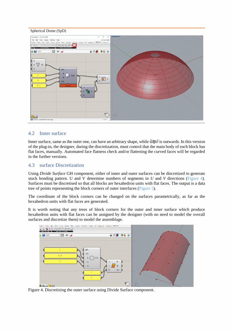
Spherical Dome (SpD)
4.2 Inner surface
Inner surface, same as the outer one, can have an arbitrary shape, while �⃗� ⨂𝑣 is outwards. In this version
of the plug-in, the designer, during the discretization, must control that the main body of each block has
flat faces, manually. Automated face flatness check and/or flattening the curved faces will be regarded
in the further versions.
4.3 surface Discretization
Using Divide Surface GH component, either of inner and outer surfaces can be discretized to generate
stuck bonding pattern. U and V determine numbers of segments in U and V directions (Figure 4).
Surfaces must be discretised so that all blocks are hexahedron units with flat faces. The output is a data
tree of points representing the block corners of outer interfaces (Figure 5).
The coordinate of the block corners can be changed on the surfaces parametrically, as far as the
hexahedron units with flat faces are generated.
It is worth noting that any trees of block corners for the outer and inner surface which produce
hexahedron units with flat faces can be assigned by the designer (with no need to model the overall
surfaces and discretize them) to model the assemblage.
Figure 4. Discretizing the outer surface using Divide Surface component.
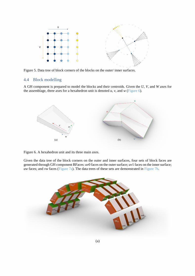
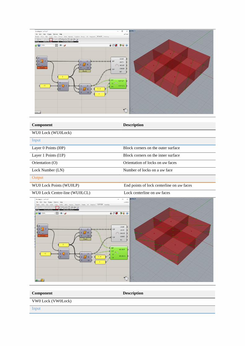
Figure 5. Data tree of block corners of the blocks on the outer/ inner surfaces.
4.4 Block modelling
A GH component is prepared to model the blocks and their centroids. Given the U, V, and W axes for
the assemblage, three axes for a hexahedron unit is denoted u, v, and w (Figure 6).
Figure 6. A hexahedron unit and its three main axes.
Given the data tree of the block corners on the outer and inner surfaces, four sets of block faces are
generated through GH component BFaces: uv0 faces on the outer surface; uv1 faces on the inner surface;
uw faces; and vw faces (Figure 7a). The data trees of these sets are demonstrated in Figure 7b.
(a)

(b)
Figure 7. four sets of block faces and their data threes.
Component Description
Block Faces and Centroids (BFaces)
Input
Layer 0 Points (l0P) Block corners on the outer surface
Layer 1 Points (l1P) Block corners on the inner surface
Output
UV0 Faces (UV0F) Faces on the outer surface
UV1 Faces (UV1F) Faces on the inner surface
WU0 Faces (WU0F)* uw faces
VW0 Faces (WV0F) vw faces
Block Centroids (BC) Centroids of blocks
* In the future the plugin enables the designers to model multi-layer assemblages. uw and vw faces of
Layer i will be denoted WUi and VWi.

4.5 Interlocking Interface Modelling
The designer can model the faces of each sets introduced in the previous section as interlocking faces.
Four GH components to model interlocking faces are outlined as follows:
Component Description
UV0 Lock (UV0Lock)
Input
Layer 0 Points (l0P) Block corners on the outer surface
Orientation (O) Orientation of locks on uv faces of the outer surface
Lock Number (LN)* Number of locks on a uv face of the outer surface
Output
UV0 Lock Points (UV0LP) End points of lock centerline on uv faces of the outer surface
UV0 Lock Centre-line (UV0LCL) Lock centerline on uv faces of the outer surface
* Lock number must be greater than or equal to 2. Otherwise the structural analysis doesn’t work.
Component Description
UV1 Lock (UV1Lock)
Input
Layer 1 Points (l1P) Block corners on the inner surface
Orientation (O) Orientation of locks on uv faces of the inner surface
Lock Number (LN) Number of locks on a uv face of the inner surface
Output
UV1 Lock Points (UV1LP) End points of lock centerline on uv faces of the inner surface
UV1 Lock Centre-line (UV1LCL) Lock centerline on uv faces of the inner surface
Component Description
WU0 Lock (WU0Lock)
Input
Layer 0 Points (l0P) Block corners on the outer surface
Layer 1 Points (l1P) Block corners on the inner surface
Orientation (O) Orientation of locks on uw faces
Lock Number (LN) Number of locks on a uw face
Output
WU0 Lock Points (WU0LP) End points of lock centerline on uw faces
WU0 Lock Centre-line (WU0LCL) Lock centerline on uw faces
Component Description
VW0 Lock (VW0Lock)
Input
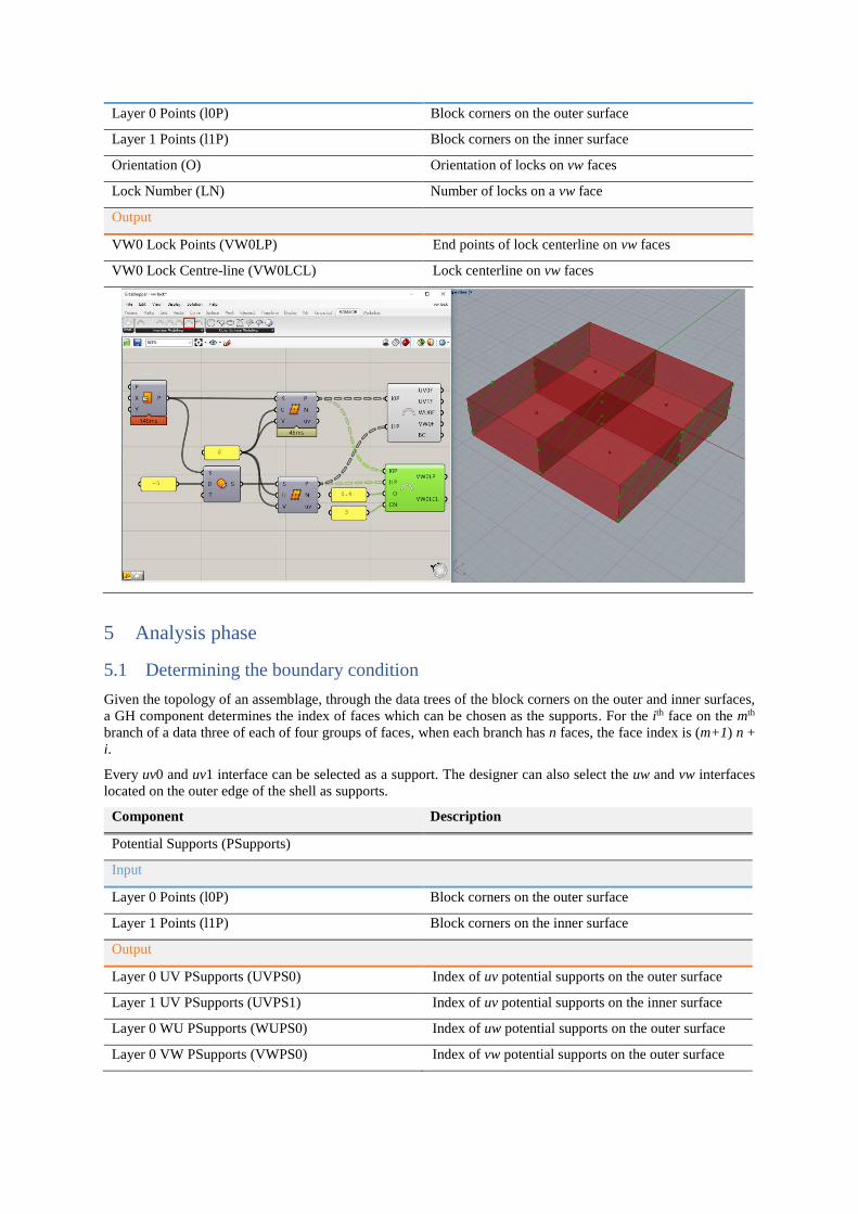
Layer 0 Points (l0P) Block corners on the outer surface
Layer 1 Points (l1P) Block corners on the inner surface
Orientation (O) Orientation of locks on vw faces
Lock Number (LN) Number of locks on a vw face
Output
VW0 Lock Points (VW0LP) End points of lock centerline on vw faces
VW0 Lock Centre-line (VW0LCL) Lock centerline on vw faces
5 Analysis phase
5.1 Determining the boundary condition
Given the topology of an assemblage, through the data trees of the block corners on the outer and inner surfaces,
a GH component determines the index of faces which can be chosen as the supports. For the ith face on the mth
branch of a data three of each of four groups of faces, when each branch has n faces, the face index is (m+1) n +
i.
Every uv0 and uv1 interface can be selected as a support. The designer can also select the uw and vw interfaces
located on the outer edge of the shell as supports.
Component Description
Potential Supports (PSupports)
Input
Layer 0 Points (l0P) Block corners on the outer surface
Layer 1 Points (l1P) Block corners on the inner surface
Output
Layer 0 UV PSupports (UVPS0) Index of uv potential supports on the outer surface
Layer 1 UV PSupports (UVPS1) Index of uv potential supports on the inner surface
Layer 0 WU PSupports (WUPS0) Index of uw potential supports on the outer surface
Layer 0 VW PSupports (VWPS0) Index of vw potential supports on the outer surface
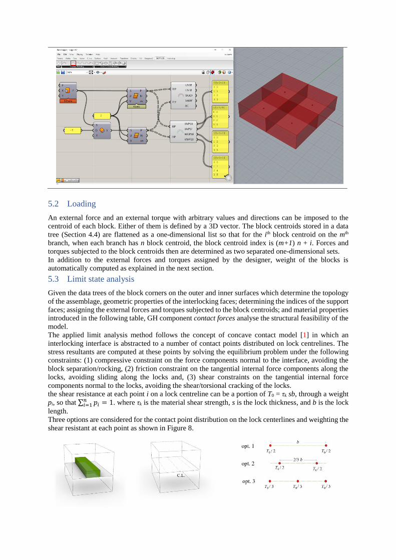
5.2 Loading
An external force and an external torque with arbitrary values and directions can be imposed to the
centroid of each block. Either of them is defined by a 3D vector. The block centroids stored in a data
tree (Section 4.4) are flattened as a one-dimensional list so that for the ith block centroid on the mth
branch, when each branch has n block centroid, the block centroid index is (m+1) n + i. Forces and
torques subjected to the block centroids then are determined as two separated one-dimensional sets.
In addition to the external forces and torques assigned by the designer, weight of the blocks is
automatically computed as explained in the next section.
5.3 Limit state analysis
Given the data trees of the block corners on the outer and inner surfaces which determine the topology
of the assemblage, geometric properties of the interlocking faces; determining the indices of the support
faces; assigning the external forces and torques subjected to the block centroids; and material properties
introduced in the following table, GH component contact forces analyse the structural feasibility of the
model.
The applied limit analysis method follows the concept of concave contact model [1] in which an
interlocking interface is abstracted to a number of contact points distributed on lock centrelines. The
stress resultants are computed at these points by solving the equilibrium problem under the following
constraints: (1) compressive constraint on the force components normal to the interface, avoiding the
block separation/rocking, (2) friction constraint on the tangential internal force components along the
locks, avoiding sliding along the locks and, (3) shear constraints on the tangential internal force
components normal to the locks, avoiding the shear/torsional cracking of the locks.
the shear resistance at each point i on a lock centreline can be a portion of T0 = τk sb, through a weight
pi, so that ∑ 𝑝𝑖𝑛𝑖=1 = 1. where τk is the material shear strength, s is the lock thickness, and b is the lock
length.
Three options are considered for the contact point distribution on the lock centerlines and weighting the
shear resistant at each point as shown in Figure 8.

Figure 8. Options for the contact point distribution of the lock centreline. Component Description
Contact Forces (CFs)
Input
Layer 0 Points (l0P) Block corners on the outer surface
Layer 1 Points (l1P) Block corners on the inner surface
Layer 0 UV Supports (UVS0) Index of uv supports on the outer surface
Layer 0 WU Supports (WUS0) Index of uw supports
Layer 0 VW Supports (VWS0) Index of vw supports
Layer 1 UV Supports (UVS1) Index of uv supports on the inner surface
UV0 Locks Points (UV0LP) End points of lock centerline on uv faces on the outer surface
UV1 Locks Points (UV1LP) End points of lock centerline on uv faces on the inner surface
WU0 Locks Points (WU0LP) End points of lock centerline on uw faces
VW0 Locks Points (VW0LP) End points of lock centerline on vw faces
External Forces (EF) External force on a block centroid
External Torques (ET) External torque on a block centroid
Friction Coefficient (FC)
Shear Strength (ShSt)
Density (D) To calculate the weight of each block
Shear Resistance Option (OP) Options for the contact point distribution of the lock centreline
Output
UV0 Internal Forces (UV0IF) Internal forces of uv faces on the outer surface
UV0 Points (UV0Points) Contact points of uv faces on the outer surface
UV1 Internal Forces (UV1IF) Internal forces of uv faces on the inner surface
UV1 Points (UV1Points) Contact points of uv faces on the inner surface
WU0 Internal Forces (WU0IF) Internal forces of uw faces
WU0 Points (WU0Points) Contact points of uw faces
VW0 Internal Forces (VW0IF) Internal forces of vw faces
VW0 Points (VW0Points) Contact points of vw faces
Residual (Res)
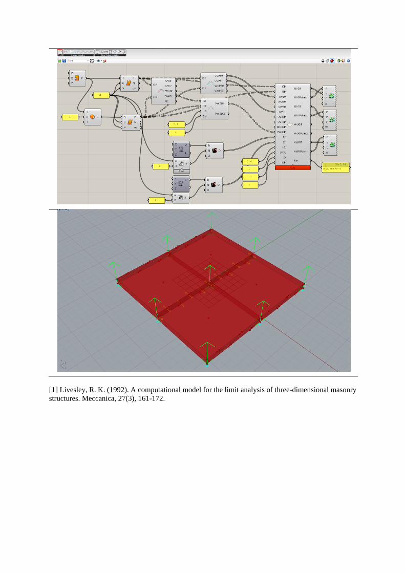
[1] Livesley, R. K. (1992). A computational model for the limit analysis of three-dimensional masonry
structures. Meccanica, 27(3), 161-172.