1. introduction - ittcjstiles/622/handouts/section_1_introduction... · 1. introduction a. history...
TRANSCRIPT

8/15/2007 Intoduction 1/3
Jim Stiles The Univ. of Kansas Dept. of EECS
1. Introduction A. History of Radio HO: A Brief History of the Radio
B. Radio Transmission Systems There are more “radios” being built than every before! 1. Telephony
* Cellular * PCS * Global Satellite Systems * Microwave Links
2. Broadcasting
* AM radio, FM radio, VHF/UHF TV * Satellite Links * Direct Broadcasting
3. Networking
* Wireless LANs * Picocells

8/15/2007 Intoduction 2/3
Jim Stiles The Univ. of Kansas Dept. of EECS
4. Radar and Navigation
* Global Positioning System (GPS) * Radar detection, tracking and imaging * Radio Frequency Identification (RFID)
Q: Just what is a radio ? A: A device that transfers information to a distant site, by means of unbounded electromagnetic propagation.
A radio system has three sections, with antennas serving as couplers between each section:
1. HO: The Radio Transmitter 2. HO: The Propagation Channel 3. HO: The Radio Receiver
D. The Electromagnetic Spectrum We can propagate energy anywhere within the electromagnetic spectrum, but we typically use frequencies less than, say, 40 GHz. HO: The Electromagnetic Spectrum HO: FCC Spectrum Chart

8/15/2007 Intoduction 3/3
Jim Stiles The Univ. of Kansas Dept. of EECS
Q: Why don’t we use frequencies greater then 40 GHz ? A: Two reasons:
1) The difficulty in making electronic components.
2) The Earth’s atmosphere rapidly attenuates the propagating wave!

The History of Radio• The history of radio can be traced
through the lives of these people:– Maxwell– Hertz– Heavyside– Marconi– DeForest– Armstrong– Farnsworth– Sarnoff

James Clerk Maxwell• Unified Electric and
Magnetic Theory.• Predicted
Electromagnetic Wave Propagation
• Theorized that lightwas an electromagnetic wave.
• Could “low-frequency” waves be generated ?
James Clerk Maxwell (1831-1879)
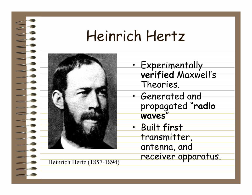
Heinrich Hertz
• Experimentally verified Maxwell’s Theories.
• Generated and propagated “radio waves”
• Built firsttransmitter, antenna, and receiver apparatus.
Heinrich Hertz (1857-1894)

Guglielmo Marconi
• The “inventor of radio”.
• Improved and commercialized Hertz’ apparatus.
• Used for radio telegraphy.
• Among the first radio engineers. (1874-1937)
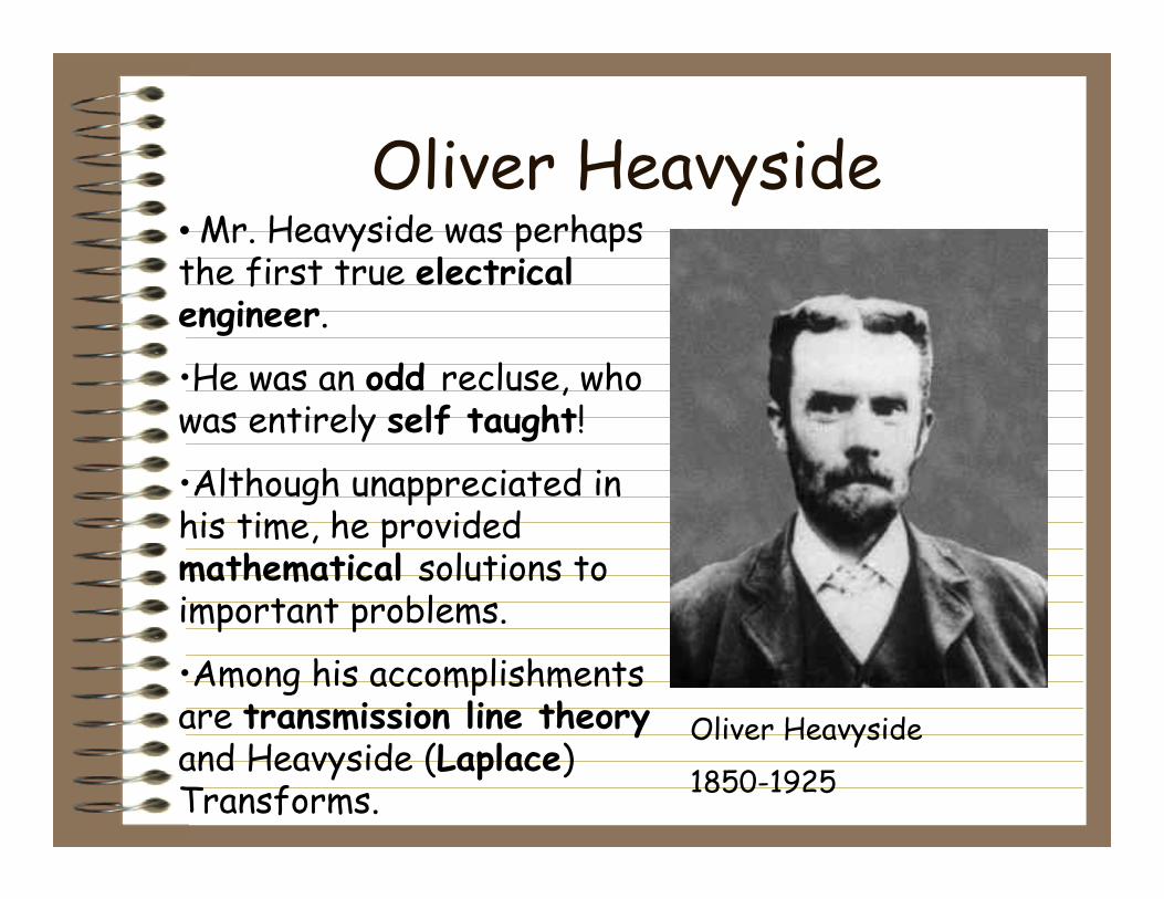
Oliver Heavyside• Mr. Heavyside was perhaps the first true electrical engineer.
•He was an odd recluse, who was entirely self taught!
•Although unappreciated in his time, he provided mathematical solutions to important problems.
•Among his accomplishments are transmission line theoryand Heavyside (Laplace) Transforms.
Oliver Heavyside
1850-1925

Lee DeForest
• Invented the “audion” vacuum tube.
• Allowed for ampflication and detection.
• Led to first transmission of voice and music.
Lee DeForest (1873-1961)
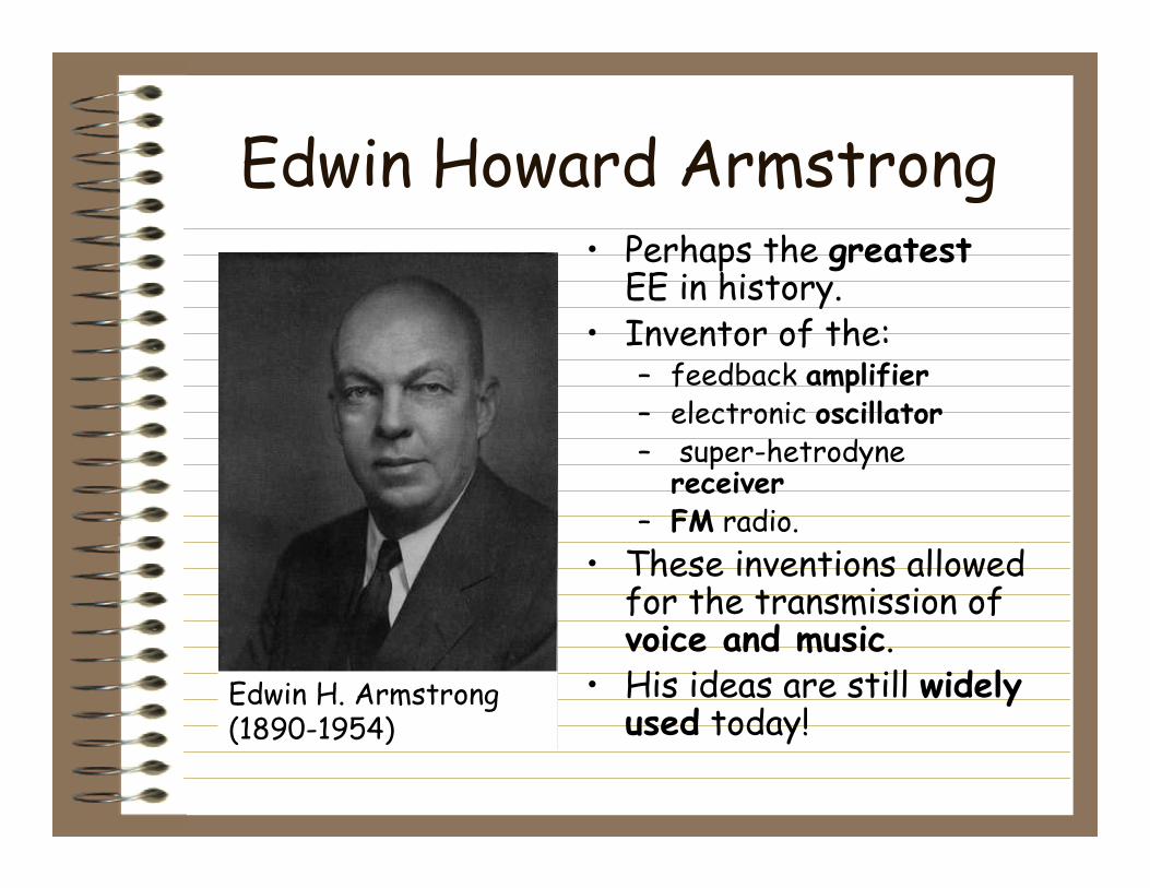
Edwin Howard Armstrong• Perhaps the greatest
EE in history.• Inventor of the:
– feedback amplifier– electronic oscillator– super-hetrodyne
receiver – FM radio.
• These inventions allowed for the transmission of voice and music.
• His ideas are still widely used today!
Edwin H. Armstrong (1890-1954)

Philo T. Farnsworth• Inventor of
electronic television.• Largely self-taught.• Developed initial
design while in high school!
• A victim of bad timing and small capital. Philo T. Farnsworth (1907-1971)

David Sarnoff• Began as telegraph
operator for Marconi.• Originated idea of
“broadcasting.”• Became president of
the Radio Corporation of America
• Was not an engineer —and the only guy who became really wealthy!

8/15/2007 The Radio Transmitter 1/2
Jim Stiles The Univ. of Kansas Dept. of EECS
The Radio Transmitter
There are 5 main components of a transmitter:
1) The signal a(t) 2) The radio frequency (RF) source 3) The modulator 4) The amplifier 5) The antenna
The Radio Transmitter System
modulator s(a,ω0)
cos ω0t
a (t)
antenna
RF source
amplifier
ω0( ,a ,r )e

8/15/2007 The Radio Transmitter 2/2
Jim Stiles The Univ. of Kansas Dept. of EECS
Let’s examine each component: 1) The signal a(t) – This is the information we are trying to transmit. It may be in either digital or analog form. It also may have been encoded to remove redundancy, in a process known as source coding. 2) RF source – Generates electromagnetic energy at RF/microwave frequencies that are suitable for electromagnetic propagation (subject to FCC restrictions !). 3) Modulator – Places signal a(t) (i.e., the information) onto the RF signal, known as the carrier. Accomplished by modulating some parameter of the carrier signal – e.g., magnitude, phase, frequency, or some combination thereof. In general, this process is called channel coding. Its goal is to maximize the rate at which information is sent, while minimizing the effect of unknown channel parameters. 4) Power Amplifier – Increases the power (i.e., energy flow) of the modulated carrier signal, without (hopefully) distorting it. 5) Antenna – Acts as the coupling mechanism between the bounded e.m. wave of a transmission line and the unbounded propagating wave in space. Often, an antenna is required to launch the unbounded wave in a specific direction.

8/15/2007 The Propagation Channel 1/1
Jim Stiles The Univ. of Kansas Dept. of EECS
The Propagation Channel The propagation channel – The space between the antennas! * Ideally, the channel is free-space (i.e., nothing). * In reality, the channel is full of stuff !
E.G., buildings, trees, rain, plasma, gasses, and the Earth.
Problem : This “stuff” modifies the propagating wave. Therefore, we must consider the e.m. phenomena of:
* scattering
* refraction
* reflection
* diffraction
* extinction
channel Tx Rx

8/15/2007 The Radio Receiver 1/3
Jim Stiles The Univ. of Kansas Dept. of EECS
The Radio Receiver
There are 8 basic components in a radio receiver:
1) Antenna 2) Low-noise Amplifier (LNA) 3) Preselection Filter 4) Local Oscillator/Mixer 5) Intermediate Frequency (IF) Amplifier 6) IF Filter 7) Detector/Demodulator 8) The recovered signal a(t)
A receiver design schematic I found on the web. Note the amplifier (amp), oscillator (osc), mixer (mix), and filter (filt) sections.

8/15/2007 The Radio Receiver 2/3
Jim Stiles The Univ. of Kansas Dept. of EECS
Let’s examine each component:
1) Antenna – Couples the incoming e.m. propagating wave into the receiver.
2) Low-Noise Amplifier – Boosts the power of the initial
signal above the receiver noise. 3) Preselector Filter – Allows only the frequency band of
interest to pass into the receiver (e.g., for FM radio 88-108 MHz).
4) Local Oscillator/Mixer – Translates the signal from its
propagation frequency to a lower, fixed intermediate frequency (IF).
5) IF Amplifier – A high-gain amplifier that greatly
increases signal power (i.e., to a detectable level). 6) IF Filter - Allows only the signal of interest to pass.
Bandwidth is typically that of the desired signal. (e.g., 200 kHz for FM radio, 20 kHz for AM radio).
7) Detector/Demodulator – Extracts the signal information
(or, at least tries to !) from the IF signal. 8) The Recovered Signal a(t) - The receiver’s “guess” at
what the original signal was. Ideally, a(t) = a(t) , but channel propagation “uncertainties” and noise make perfect reproduction impossible !

8/15/2007 The Radio Receiver 3/3
Jim Stiles The Univ. of Kansas Dept. of EECS
antenna
LNA
mixer
IF filter
Dem
odulator/ D
etector
local oscillator
IF
a(t) The Basic Radio Receiver A
“ Super Heterodyne”
preselector filter
The “recovered “ signal

8/15/2007 The Electromagnetic Spectrum 1/2
Jim Stiles The Univ. of Kansas Dept. of EECS
The Electromagnetic Spectrum
Below is a description of standard Radio Frequency “Bands”, as well as the applications that use them.
Band Frequency Extremely Low Frequency (ELF) 0 to 3 KHz
Very Low Frequency (VLF) 3 KHz to 30 KHz
Radio Navigation & maritime/aeronautical mobile 9 KHz to 540 KHz
Low Frequency (LF) 30 KHz to 300 KHz
Medium Frequency (MF) 300 KHz to 3000 KHz
AM Radio Broadcast 540 KHz to 1630 KHz
Travelers Information Service 1610 KHz
High Frequency (HF) 3 MHz to 30 MHz
Shortwave Broadcast Radio 5.95 MHz to 26.1 MHz
Very High Frequency (VHF) 30 MHz to 300 MHz
Low Band: TV Band 1 - Channels 2-6 54 MHz to 88 MHz
Mid Band: FM Radio Broadcast 88 MHz to 174 MHz
High Band: TV Band 2 - Channels 7-13 174 MHz to 216 MHz
Super Band (mobile/fixed radio & TV) 216 MHz to 600 MHz
Ultra-High Frequency (UHF) 300 MHz to 3000 MHz
Channels 14-70 470 MHz to 806 MHz
L-band: 500 MHz to 1500 MHz
Canada DARS 1452 MHz to 1492 MHz
Personal Communications Services (PCS) 1850 MHz to 1990 MHz
Unlicensed PCS Devices 1910 MHz to 1930 MHz
8/15/2007 The Electromagnetic Spectrum 2/2
Jim Stiles The Univ. of Kansas Dept. of EECS
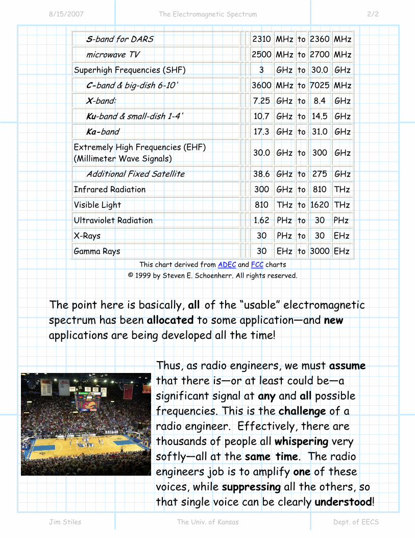
S-band for DARS 2310 MHz to 2360 MHz
microwave TV 2500 MHz to 2700 MHz
Superhigh Frequencies (SHF) 3 GHz to 30.0 GHz
C-band & big-dish 6-10' 3600 MHz to 7025 MHz
X-band: 7.25 GHz to 8.4 GHz
Ku-band & small-dish 1-4' 10.7 GHz to 14.5 GHz
Ka-band 17.3 GHz to 31.0 GHz
Extremely High Frequencies (EHF) (Millimeter Wave Signals) 30.0 GHz to 300 GHz
Additional Fixed Satellite 38.6 GHz to 275 GHz
Infrared Radiation 300 GHz to 810 THz
Visible Light 810 THz to 1620 THz
Ultraviolet Radiation 1.62 PHz to 30 PHz
X-Rays 30 PHz to 30 EHz
Gamma Rays 30 EHz to 3000 EHz This chart derived from ADEC and FCC charts
© 1999 by Steven E. Schoenherr. All rights reserved.
The point here is basically, all of the “usable” electromagnetic spectrum has been allocated to some application—and new applications are being developed all the time!
Thus, as radio engineers, we must assume that there is—or at least could be—a significant signal at any and all possible frequencies. This is the challenge of a radio engineer. Effectively, there are thousands of people all whispering very softly—all at the same time. The radio engineers job is to amplify one of these voices, while suppressing all the others, so that single voice can be clearly understood!