1 design of uwb bandpass filter using triangular ring mmr with stub – loaded resonator yung-wei...
TRANSCRIPT
1
Design of UWB Bandpass Filter Using Triangular ring MMR With
Stub – Loaded Resonator
Yung-Wei Chen
Department of Computer and Communication, Kun Shan University, Taiwan
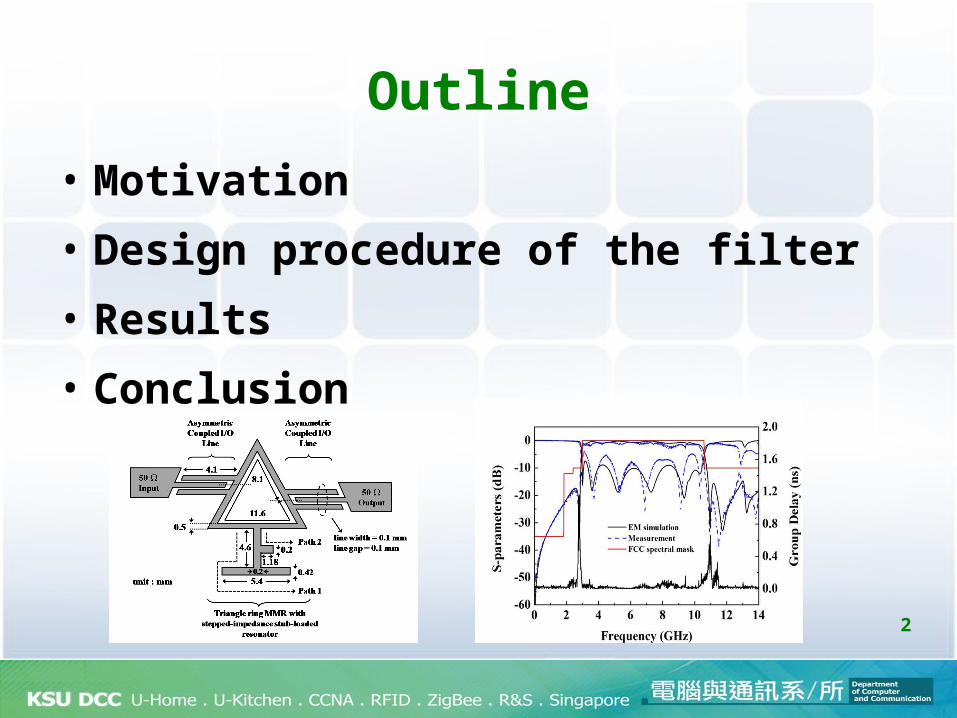
Outline
• Motivation
• Design procedure of the filter
• Results
• Conclusion
2

Motivation
3
IEEE 802.11a

Motivation – Paper review (1)• L. Zhu et al. proposed the UWB filter used a multiple-mode resonator (MMR) with tight coupling I/O
lines to generate a wideband response.
• S. W. Wong et al. proposed the ultra-wideband bandpass filters using short-/open-stubs embedded ring resonator. The square ring resonator is first excited by two interdigital coupled-lines at two sides to achieve a triple-mode ultra-wideband bandpass filter performance
L. Zhu, S. Sun, and W. Menzel, “Ultra-wideband (UWB) bandpass filters using multiple-mode resonator,” IEEE Microw. Wireless Compon. Lett., vol. 15, no. 11, pp. 796–798, Nov. 2005. S. W. Wong, L. Zhu, L. C. Quek and Z. N. Chen, “A stopband-enhanced UWB bandpass filter using shout-/open- stubs embedded ring resonator,” in Proc. IEEE Asia-Pacific Microw. Conf., Dec. 2009, pp. 913-916.
5
Motivation – Paper review (2)
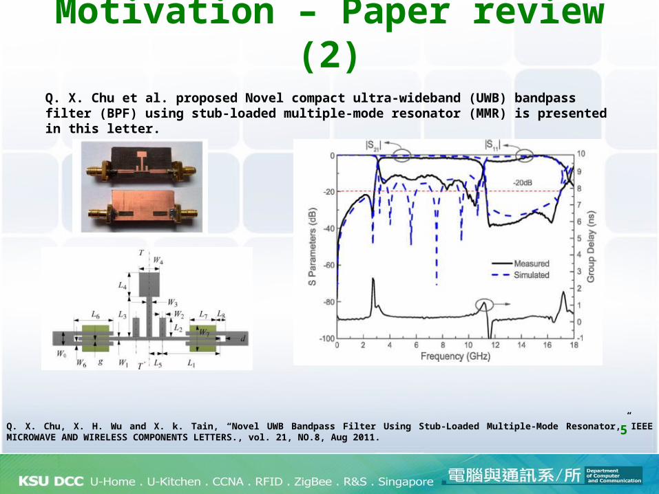
Q. X. Chu et al. proposed Novel compact ultra-wideband (UWB) bandpass filter (BPF) using stub-loaded multiple-mode resonator (MMR) is presented in this letter.
Q. X. Chu, X. H. Wu and X. k. Tain, “Novel UWB Bandpass Filter Using Stub-Loaded Multiple-Mode Resonator,” IEEE MICROWAVE AND WIRELESS COMPONENTS LETTERS., vol. 21, NO.8, Aug 2011.

6
Motivation – UWB bandpass filter using Triangular ring MMR
Duroid 6010 substrate with a relative dielectric constant of 10.2, a loss tangent of 0.0023 and a thickness of 1.27 mm is used for the simulation and practical fabrication.
Lower transmission zero
Upper transmission zero
There are two directions of this study :
1. To design UWB filter using Triangular ring MMR with coupling lines;
2. Triangular ring MMR add to the SLR composed of two transmission zeros
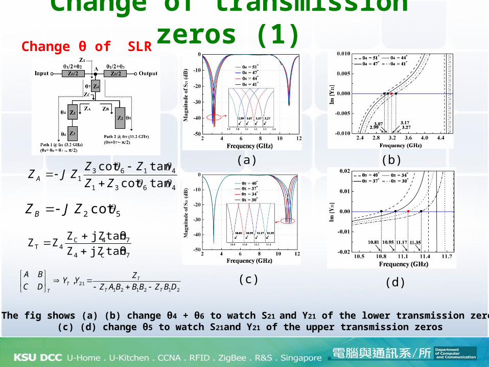
Change of transmission zeros (1)
The fig shows (a) (b) change θ4 + θ6 to watch S21 and Y21 of the lower transmission zeros(c) (d) change θ5 to watch S21and Y21 of the upper transmission zeros
(a) (b)
(c) (d)
4631
41631 tancot
tancot
ZZ
ZZZJZ A
52 cot ZJZ B
7C4
74C4T tanθjZZ
tanθjZZZZ
21212121,
DBZBBBAZ
ZYY
DC
BA
TT
TT
T
Change θ of SLR
8
(a) (b)
(c) (d)
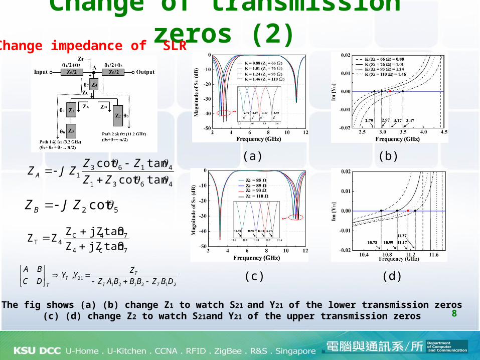
Change of transmission zeros (2)
The fig shows (a) (b) change Z1 to watch S21 and Y21 of the lower transmission zeros(c) (d) change Z2 to watch S21and Y21 of the upper transmission zeros
4631
41631 tancot
tancot
ZZ
ZZZJZ A
52 cot ZJZ B
7C4
74C4T tanθjZZ
tanθjZZZZ
21212121,
DBZBBBAZ
ZYY
DC
BA
TT
TT
T
Change impedance of SLR

9
Measured results of the filter
The measured results of the filter have a 3 dB FBW of 117%
The SLR(stub-loaded resonator) is designed with two transmission
zeros at 2.8 and 11GHz

10
Passband (GHz) 3.1-10.6 3.1-10.6 2.9-11.6 3.1-10.6
Substrateheight (mm) / εr
(PCB)0.81/ 3.38
(PCB)1.27 / 10.6
(PCB)0.787 / 2.2
(PCB)1.27 / 10.2
Return loss (dB) 18 14 20 20(max)
Insertion loss (dB) <0.5 <0.2 <0.5 <0.5
3-dB FBW (%) 109 109 122 111
Circuit Size (mm2)(λg×λg)
251(0.77×0.54)
175(1.64×0.59)
594(0.96×0.78)
128.2(1.11×0.62)
Comparisons with other proposed UWB filters
P-K. Singh, S. Basu, and Y-H. Wang, “Planar Ultra-Wideband Bandpass Filter Using Edge Coupled Microstrip Lines and Stepped Impedance Open Stub,” IEEE Microw. Wireless Compon. Lett., vol. 17, no. 9, pp. 649–651, Sep. 2007.C-P. Chen, Z. Ma, N. Nagaoka, and T. Anada, “Novel Compact Ultra-Wideband Bandpass Filter Employing Short-circuited Stubs with Coupled Stepped-Impedance Resonator,” Proceedings of Asia-Pacific Microwave Conference 2007., R. Ghatak, P. Sarkar, R.k. Mishra, and D.R. Poddaer “A Compact UWB Bandpass Filter With Embedded SIR as Band Notch Structure,” IEEE Microw. Wireless Compon. Lett., vol. 21, no. 5, pp. 261–263, MAY. 2011

11
Thanks for your attention !!