1. balancing techniques for
TRANSCRIPT
NASA Contractor Report 2975
Balancing Techniques for 1 .
AF
High-speed Flexible Rotors
A. J. Smalley, J. M. Tessarzik, and R. A. Rio
CONTRACT NAS3- 18 5 2 0 APRIL 1978

TECH LIBRARY KAFB. NY
NASA Contractor Report 2975
Balancing Techniques for High-speed Flexible Rotors
A. J. Smalley, J. M. Tessarzik, and R. A. Rio Mechanical Techlzology, I w . Latham, New York
Prepared for Lewis Research Center under Contract NAS3-18520
National Aeronautics and Space Administration
Scientific and Technical Information Office
1978


TABU OF CONTENTS
Page
SUMMARY . . . . . . . . . . . . . . . . . . . . . . . . . . . . . . . . 1
INTRODUCTION . . . . . . . . . . . . . . . . . . . . . . . . . . . . . 2
DESIGN OF A SHAFT WITH FLEXURAL ASYMMETRY . . . . . . . . . . . . . . . 4
Tes t Appara tus and In s t rumen ta t ion . . . . . . . . . . . . . . . . 4
Design of Asymrne t r i c S h a f t . . . . . . . . . . . . . . . . . . . . 6
I n i t i a l T e s t R e s u l t s . . . . . . . . . . . . . . . . . . . . . . . 1 2
Redes ign of Tes t Rotor . . . . . . . . . . . . . . . . . . . . . . 22
BALANCING RESULTS . . . . . . . . . . . . . . . . . . . . . . . . . . . 29
Ba lanc ing w i th F l exura l Asymmetry . . . . . . . . . . . . . . . . 29
Balancing with Resonant Probe Holders . . . . . . . . . . . . . . 3 4
T r i a l Weight Placement . . . . . . . . . . . . . . . . . . . . . . 42 F i l t e r Randwidth Var ia t ions . . . . . . . . . . . . . . . . . . . 45
GUIDELIKES'AND CRITERIA FOR LOCATION OF PLANES AND SENSORS . . . . . . 5 0
E v a l u a t i o n of P l ane -Probe Loca t ions u s ing Modal A n a l y s i s . . . . . 5 4
E v a l u a t i o n of P la r ie -Probe Loca t ions us ing Balanc ing S imula t ion . . 58
EVALUATION OF C R I T E R I A FOR BALANCE PLANE AND SENSOR LOCATIONS . . . . . 6 1
Uni form Shaf t on Rig id Suppor ts . . . . . . . . . . . . . . . . . 6 1
Balance P lane Loca t ion . Three Mode Ba lanc ing . . . . . . . . . . 62
S e l e c t i o n o f P r o b e L o c a t i o n s . Three Mode Ba lanc ing . . . . . . . 66
Balance P lane Loca t ion . Four Modk Ba lanc ing . . . . . . . . . . . 68
U n i f o r m S h a f t i n F l e x i b l e , Damped Bea r ings . . . . . . . . . . . . 69
REFERENCES . . . . . . . . . . . . . . . . . . . . . . . . . . . . . . 82
APPENDIX A . ANALYTICAL DEVELOPMENT OF CRITERIA FOR BALANCE PLANE AND SENSOR LOCATION . . . . . . . . . . . . . . . . . . . 84
APPEXDIX B . STABILITY OF A SHAFT WITH FLEXURAL ASYMMETRY . . . . . . . 101
APPESDIX C . PlTI CONMASDT' NLJLTIPLANE. MULTISPEED BALANCING SYSTEM . . . 115
iii

LIST OF ILLUSTRATIONS
T i t l e Page
1 Test Rig Assembly wi th F la t Shaf t 5 """""""""""""-
2 T e s t Rotors 7
3 C a l c u l a t e d Undamped Th i rd Cr i t ica l S p e e d s f o r t h e M o d i f i e d Test R o t o r w i t h F l a t S e c t i o n s 9
"""""""""""""""~
4 C r i t i c a l S p e e d Map f o r F l e x i b l e - R o t o r Test Rig (Rotor w i t h F l a t S e c t i o n s , C r i t i ca l S p e e d s A s s o c i a t e d w i t h t h e R o t o r I n e r t i a Axis AA) 10
"""""""""""""""""""
5 C r i t i c a l Speed Map f o r F l e x i b l e - R o t o r T e s t Rig (Rotor with F l a t S e c t i o n s , Cr i t ica l Speeds Assoc ia t ed w i th t he Ro to r I n e r t i a A x i s BB) 11
""""""""""""""""""""""
6 Undamped Rotor Mode Shape a t t h e F i r s t S y s t e m C r i t i c a l Speed fo r Test R o t o r w i t h F l a t S e c t i o n s ( B e a r i n g P r e l o a d F a c t o r rn = 0.3) 1 3
""""""""""~""""""""""""
7 Undamped Rotor Mode Shapes a t the Second System Cr i t ica l Speed fo r Test R o t o r w i t h F l a t S e c t i o n s (Bea r ing P re load F a c t o r m = 0 . 3 ) 14
" """""""""""""""""""""-
8 Undamped Rotor Mode 'Shapes a t t h e T h i r d S y s t e m C r i t i c a l ''
Speed for Test R o t o r w i t h F l a t S e c t i o n s (Bea r ing P re load F a c t o r m = 0 . 3 ) 1 5
.......................
9 Camped Rotor Amplitudes a t t h e T h i r d S y s t e m C r i t i c a l S p e e d f o r Test Rotor wi th F l a t S e c t i o n s ( B e a r i n g P r e l o a d F a c t o r rn = 0 . 3 ; In-Line, In-Phase Unbalance Configurat ion) 16 - - - - - - - - -
10 Undamped Kotor Mode Shapes a t t h e F i r s t S y s t e m C r i t i c a l Speed fo r Test Rotor w i t h F l a t S e c t i o n s ( R e a r i n g P r e l o a d F a c t o r m = 0.5) 1 7 _""""""""""""""""""""""
11 Undamped RoEor Mode Shapes a t t h e Second Sys t em Cr i t i ca l Speed fo r Test Rotor wi th F l a t Sec t ions (Bea r ing P re load F a c t o r m = 0.5) 18 """""""""_"""""""""""""
1 2 Undamped Rotvr Mode Shapes a t t h e T h i r d S y s t e m C r i t i c a l S p e e d f o r Test R o t o r w i t h F l a t S e c t i o n s (Bea r ing P re load F a c t o r m = 0.5) 1 9 """""""""_"""""""""""""
1 3 G r a v i t a t i o n a l E x c i t a t i o n o f R o t o r w i t h 6 . 5 1 cm Diameter a t F l a t : S e c t i o n 2 1 """_ """""""""""""""""""
1 4 Ver t ica l Rotor Ampl i tudes a t S h a f t C e n t e r - I n i t i a l Condi- t i o n and a f t e r One Balancing Run ( F i v e v e r t i c a l p r o b e s , r o t o r w i t h f l a t s e c t i o n s a n d two end masses, 4 . 9 4 kg each)---- 2 3
i v
. . . . ... .. . . - . ..... . .."_

1 5
1.6
17
18
1 9
20
2 1
22
23
24
2 5
26
27
28
29
30
3 1
S t a b i l i t y A n a l y s i s - Real Par t o f Root V e r s u s Speed f o r D i f f e ren t Ma jo r D iame te r s
""""""""""""""""""
S t a b i l i t y A n a l y s i s - Real P a r t of Synchronous Root Versus Major Diameter ( D i s t a n c e A c r o s s F l a t s = 4.48 cm) """
Vertical Rotor Amplitudes a t Sha f t Cen te r - I n i t i a l C o n d i t i o n and Af t e r One Balanc ing Run by t h e Least Squa res P rocedure ( F o u r V e r t i c l e P r o b e s , R o t o r w i t h 5.72 c m Diameter a t F l a t Sec t ions and One Aluminum End Mass)
Vertical Rotor Ampli tudes a t S h a f t C e n t e r - I n i t i a l R o t o r Cond i t ion (Corksc rew Unba lance D i s t r ibu t ion ) and Af t e r One Ba lanc ing Run by t h e 'Least Squa res P rocedure (F ive .
Vertical P robes , Ro to r w i th 6 . 5 1 cm Diameter a t F l a t Sec t ions and One Aluminum End Mass)
Ver t i ca l Ro to r Ampl i tudes a t Sha f t Cen te r - I n i t i a l Con- d i t i o n and Af te r One and Two Ba lanc ing Runs (Four Ver t i ca l Probes , Rotor wi th 4.80 cm Diameter a t F l a t S e c t i o n s and One Aluminum End lqass)
Test Rig wi th F la t Shaf t and F lex ib ly-Mounted Probe Holders "
"""""""""""""
"""""~"""""""~
""~""""~""""~""""""""
Vibrat ion Response of Mid-Plane Flexible Probe Holder D u r i n g t h e I n i t i a l R u n n i n g w i t h a D i s t r ibu ted Unba lanced Rotor
""""""""""""""""""" """""""""
Vertical Response a t t h e F r e e End Disk w i th t he P robe Mounted i n a F l e x i b l e B r a c k e t
""""""""""""""""
Vert ical Response a t t h e C e n t e r D i s k w i t h t h e P r o b e Mounted i n a F l e x i b l e B r a c k e t
Vertical Response a t t h e Motor End D i s k w i t h t h e P r o b e Mounted i n a F l e x i b l e B r a c k e t
V ib ra t ion S igna l Recorded on t he Mid-P lane Disk------,,,,,,,-
""""""""""""""""
"""""""""~""""""~
V i b r a t i o n O r b i t S i g n a l as Recorded From a Resonant Vertical Probe and Hard Mounted Horizontal Probe on the Free End Disk a t 7130 rpm
"""""""""""""""""""""""""
Vertical Response a t t h e Motor End Disk
Vertical Response a t t h e Motor End Disk
"""""""""""
"""""""""""
Vertical Response a t t h e Motor End Disk ""_""""""""- Vertical Response a t t h e C e n t e r D i s k
""""""""""""~
Mul t ip l ane Ba lanc ing P rocedure f o r S e l e c t i o n of P l a n e s and Probes
""""~"""""""""""""""""""""
25
2 6
30
3 2
33
35
36
37
3 8
39
41
4 3
44
46
47
49
5 1
V

32
33
3 4
35
36
37
3 8
39
40
41
4 2
4 3
44
45
46
In f luence o f P l ane 1 on Normalized Sum of Cor rec t ion Weigh t s fo r Un i fo rm Sha f t on R ig id Bea r ings and Three Cr i t i ca l s
“””_
Mode Shapes for Uni form- Shaf t in Rig id Suppor ts ”“”””””_
Effec t o f P robe 1 and 3 Loca t ion on P r o b e S e n s i t i v i t y Funct ions for Uni form Shaf t on Rig id Bear ings
In f luence o f P l anes 2 and 3 on Normalized Sum o f C o r r e c t i o n Weights for Uni form Shaf t on Rig id Bear ings and Four Cr i t ica l s (Coordina te o f P lane No. 1 = 0.05)
”””””””_“
””””~””””_
In f luence o f P l anes 2 and 3 on Normalized Sum of Cor rec t ion Weights for Uni form Shaf t on Rig id Bear ings and Four C r i t i c a l s ( C o o r d i n a t e o f P l a n e No. 1 = 0.125)
In f luence o f P l anes 2 and 3 on Normalized Sum of C o r r e c t i o n Weights for Uni form Shaf t on Rig id Bear ings and Four C r i t i c a l s ( C o o r d i n a t e of Plane No. 1 = 0 . 1 6 7 )
””””””””_
””””””””_
In f luence o f P l ane 1 Locat ion on Normalized Sum o f C o r r e c t i o n Weights for Uni form Shaf t on Rig id Bear ings and Four C r i t i c a l s ( C o o r d i n a t e of Plane No. 1 = 0 . 2 5 )
In f luence o f P l anes 2 and 3 on Normalized Sum o f C o r r e c t i o n Weigh t s fo r Un i fo rm Sha f t on R ig id Bea r ings and Four C r i t i c a l s ( C o o r d i n a t e o f P l a n e No. 1 = 0 . 3 3 3 )
Normalized Mode S h a p e s f o r F i r s t F o u r Cr i t ica l S p e e d s f o r a
“”””“”””“
”””“””””_
Uniform Rotor on F lex ib le , Damped Suppor ts ”””””““””“
I n f l u e n c e o f P l a n e 2 Locat ion on Normal ized Sum of Correc- t i o n W e i g h t s f o r U n i f o r m S h a f t o n F l e x i b l e , Damped Suppor t s (Coord ina te o f P l ane No. 1 = 0.0)
””””””””””””””-
I n f l u e n c e o f P l a n e 2 Locat ion on Normalized Sum of Cor rec - t i o n W e i g h t s f o r U n i f o r m S h a f t o n F l e x i b l e , Damped Suppor t s (Coordina te o f P lane No. 1 = 0 . 0 4 1 7 )
”””””””””””””
I n f l u e n c e o f P l a n e 2 Locat ion on Normalized Sum of Correc- t i o n W e i g h t s f o r U n i f o r m S h a f t o n F l e x i b l e , Damped Suppor t s (Coordina te o f P lane No. 1 = 0 . 0 8 3 3 )
””“””””””””””
I n f l u e n c e o f P l a n e 2 Locat ion on Normalized Sum of Correc- t i o n W e i g h t s f o r U n i f o r m S h a f t o n F l e x i b l e , Damped Suppor t s (Coord ina te o f P l ane 1 = 0 . 1 2 5 )
””””-”””””””””””
Sign Conven t ion fo r Rad ia l D i sp lacemen t , Angu la r D i sp lace - ment, Bending Moment, and Shear Force
”””””””””“””-
Rela t ionship Between F ixed and Kota t ing Coordina te Frames ””_
64
65
67
70
7 1
72
73 .
74
76
7 8
79
80
8 1
104
105
vi

47
48
49
Alignment of Principal Axes with Rotating Coordinate 109
Check of Stability Analysis for Asymmetric Shaft 114
MTI Command Model 2005 Balancing System 118
””“””
”””””””
TM ””””””””””-
vi i

Number
LIST OF TABLES
T i t l e Page
1 Test Combinations of Majo r Sha f t Diameter and End Masses ""_ 8
2 Rotor Conf igura t ions and Condi t ions 28 """""""""""""
3 Summary o f I n f o r m a t i o n O b t a i n e d D u r i n g S e l e c t i o n o f Balance P lanes and Probes 59 "-------"""""""""""~""
v i i i

LIST OF SYMBOLS
F+, F-
f n I
K
LlaL2 R
M Max.
m
damping coefficient (NS /m)
diameter
Young's modulus (N/m 2 )
distance across flats of asymmetric rotor Section
point frequencies at which amplitude = l/fi times peak amplitude resonant frequency
section transverse second moment of area
stiffness (N/m)
lengths of flattened shaft sections
shaft length
total mass of shaft
maximum
preload ratio; number of planes
modal norm
number of modes
probe configuration measure of "quality"
magnification factor
complex root
weighted sum of normalized correction weights
normalized sum of correction weights to correct unit unbalance
unit modal unbalance
correction weight set values for mode n
axial location of probes
axial location of planes
axial location
log decrement
log decrement for nth mode
normalized plane locations
real part of eigenvalue
growth exponent
mass per unit length
adjoint function
spin frequency damped natural frequency
ix

LIST OF SYMBOLS AND ABBREVIATIONS FOR APPENDIX B
NOMENCLATURE
A
- R -
B x x . B x y
DXX'Dxy
f+, f-
fn
(IOn, W n
Jtn' Jpn
E
K -
'n
Mn
M x n 9 Myn
'A M;n
N
S
T - -
t
v V'
'x,, yn "xn' yn
X n
Yn o!
B A
cross-sectional area of shaft
bearing translational damping matrix
direct and cross-coupling translation damping coefficient
angular direct and cross-coupling damping coefficient
Young's modulus, psi
frequencies (Hz) of the "half-power points" for a critical speed
resonant frequency, Elz
transverse moments of inertia about <,rl axes
transverse and polar moments of inertia at a station
bearing translational stiffness matrix
distance between station n and station n+l
concentrated mass at station n
bending moment at lower numbered side of station
bending moment at higher number side of station
number of stations
complex eigenvalue
rotor matrix relating forces and moments at one end to displacement
and slope at the other end
time
shear forces at
shear forces at
displacement in
displacement in
lower numbered side of station
higher numbered side of station
x-direction at station n
y direction at station n
angle of rotor deflection in 5 plane; also shape factor for shear deformation
angle of rotor deflection in rl plane
determinant of rotor matrix
X

AP
n x M
w
W '
determinant of rotor matrix with elements of pth column replaced by their derivatives with respect to S
log decrement
angle of rotor deflection in fixed frame
real part of eigenvalue
amplitude of displacement in E direction
rotating coordinate direction
angle of rotor deflection in fixed frame
rotational angular velocity
imaginary part of eigenvalue expressed in nonrotating frame
imaginary part of eigenvalue expressed relative to rotating coordinate frame
xi

S M A R Y
I d e n t i f i c a t i o n o f i d e a l c o n d i t i o n s f o r b a l a n c i n g a n d e v a l u a t i o n s of non-ideal
c o n d i t i o n s are t r e a t e d i n t h i s r e p o r t . Work w a s p e r f o r m e d i n t h e areas of
b a l a n c i n g a s h a f t w i t h f l e x u r a l a s y m m e t r y , b a l a n c i n g a s h a f t w i t h r e s o n a n t
s u p p o r t s f o r t h e d i s p l a c e m e n t s e n s o r s , a n d e s t a b l i s h i n g g u i d e l i n e s a n d c r i -
ter ia f o r l o c a t i o n o f b a l a n c e p l a n e s a n d s e n s o r s .
A three-mass test r o t o r w i t h a f l a t t e n e d s h a f t was d e s i g n e d t o e v a l u a t e t h e
f e a s i b i l i t y a n d p r o b l e m s o f b a l a n c i n g a r o t o r w i t h f l e x u r a l a s y m m e t r y . Two
problems encountered w i t h t h e tes t s h a f t were: a g r a v i t y e x c i t e d c r i t i c a l spee
o c c u r r i n g a t h a l f t h e f i r s t b e n d i n g c r i t i c a l speed; and an u n n e g o t i a b l e
i n s t a b i l i t y e n c o u n t e r e d a b o v e t h e l o w e r o f two bending c r i t i c a l speeds . These
were ove rcome by i nc reas ing bea r ing damping and r ed i s t r ibu t ing ro to r mass i n
t h e f i r s t c a s e and by r e d e s i g n i n g t h e s h a f t t o r e d u c e a s y m m e t r y i n t h e s e c o n d
c a s e .
F lex ib le p robe ho lders were des igned . These were a t tached to the bear ing
housings and tuned s o t h a t , i n t h e r e g i o n o f t h e f i r s t b e n d i n g c r i t i c a l s p e e d
o f t h e s h a f t , a p r o b e s u p p o r t r e s o n a n c e o c c u r r e d . B a l a n c i n g , b a s e d d i r e c t l y
on s igna l s f rom the r e sonan t p robes , was s u c c e s s f u l l y p e r f o r m e d f o r t h i s non-
i d e a l c o n d i t i o n . V a r i o u s t r i a l w e i g h t l o c a t i o n s a n d t r a c k i n g f i l t e r b a n d w i d t h s
were used during the f i n a l b a l a n c i n g e x p e r i m e n t s , a n d s u c c e s s f u l b a l a n c i n g was
accomplished i n a l l c a s e s .
An a n a l y s i s was developed and used t o q u a n t i f y t h e e f f e c L i v e n e s s o f a p a r t i c -
u l a r b a l a n c e p l a n e c o n f i g u r a t i o n i n t e r m s o f a p e n a l t y f u n c t i o n . T h i s p e n a l t y
f u n c t i o n i s based on the amount of weight to be added or removed t o c o r r e c t
f o r a u n i t u n b a l a n c e d i s t r i b u t i o n f o r e a c h mode o f v i b r a t i o n c o n s i d e r s d . A l s o ,
a func t ion , which can be u s e d t o m e a s u r e t h e s e n s i t i v i t y o f a p a r t i c u l a r
a r rangement o f d i sp lacement sensors , i s sugges t ed . These func t ions p rov ide
g u i d a n c e t o t h e d e s i g n e r who i s f a c e d w i t h t h e p r o b l e m o f s e l e c t i n g l o c a t i o n s
f o r p l a n e s a n d s e n s o r s f o r m u l t i p l a n e b a l a n c i n g . The u s e o f t h e s e f u n c t i o n s
t o m e a s u r e t h e q u a l i t y o f p l a n e a n d p r o b e l o c a t i o n s i s d e s c r i b e d a n d r e l a t e d
t o t h e o v e r a l l p r o c e s s o f d e s i g n i n g f o r m u l t i p l a n e b a l a n c i n g .
1

INTRODUCTION
F l e x i b l e r o t o r b a l a n c i n g by t h e m u l t i p l a n e - m u l t i s p e e d method is now proven
t e c h n o l o g y . F o l l o w i n g t h e a n a l y t i c a l f o r m a l i z a t i o n of the method, exac t ing and
s u c c e s s f u l l a b o r a t o r y tests o f t he me thod have been pe r fo rmed (1 ,2 ,3 ) , and a
number o f s u c c e s s f u l s o l u t i o n s t o d i f f i c u l t m a c h i n e r y v i b r a t i o n s p r o b l e m s h a v e
been ach ieved by f i e ld app l i ca tgon o f t he me thod (13 ,141 . Fu r the rmore , a
n u m b e r o f e n g i n e e r i n g s t u d i e s h a v e s h o w n , a n a l y t i c a l l y , t h e p o t e n t i a l v a l u e of
t h e m e t h o d f o r r o u t i n e b a l a n c i n g i n a wide range of h igh-speed machinery appl i -
cat i o n s .
The d e s i r a b i l i t y o f u s i n g "optimum" o r " n e a r o p t i m u m ' ' l o c a t i o n s f o r b a l a n c e
p l a n e s a n d s e n s o r s h a s b e e n shown by these demons t r a t ions and s tud ie s . However ,
i n mos t mach ines , cons t r a in t s exis t w h i c h i n h i b i t t h e u s e o f t h e optimum l o c a -
t i o n s , a n d a means t o e v a l u a t e " n o n - i d e a l " l o c a t i o n s is c l e a r l y n e c e s s a r y , A t
t h e same time, o the r "non- idea l " a spec t s o f "reall' ba lanc ing requi rements mus t
be recognized .
T h i s r e p o r t a d d r e s s e s b o t h t h e i d e n t i f i c a t i o n o f i d e a l c o n d i t i o n s f o r b a l a n c i n g
a n d t h e e v a l u a t i o n of n o n - i d e a l c o n d i t i o n s . Work i n t h r e e areas i s p r e s e n t e d :
Balanc ing 02 a s h a f t w i t h f l e x u r a l a s y m m e t r y .
Balanc ing a s h a f t u n d e r n o n - i d e a l c o n d i t i o n s w h i c h i n c l u d e d r e s o n a n t
p r o b e h o l d e r s , e x t r e m e s i n b a n d w i d t h f i l t e r s , a n d a reduced number
of t r i a l w e i g h t p l a c e m e n t s f o r d e t e r m i n i n g i n f l u e n c e c o e f f i c i e n t s .
G u i d e l i n e s a n d c r i t e r i a f o r l o c a t i o n of ba l ance p l anes and s enso r s .
To e v a l u a t e t h e f e a s i b i l i t y a n d p r o b l e m s o f b a l a n c i n g a r o t o r w i t h f l e x u r a l asym-
met ry , a r o t o r w i t h a f l a t t e n e d s h a f t was d e s i g n e d t o e x h i b i t a p p r o x i m a t e l y 20
p e r c e n t d i f f e r e n c e b e t w e e n t h e two b e n d i n g c r i t i c a l s p e e d s a s s o c i a t e d w i t h t h e
s t i f f a n d s o f t a x e s . Two p r o b l e m s w e r e e n c o u n t e r e d w i t h t h e s h a f t : f i r s t , a
g r a v i t y e x c i t e d n a t u r a l f r e q u e n c y o c c u r r e d a t h a l f t h e f i r s t b e n d i n g c r i t i c a l
speed and was made n e g o t i a b l e by increasing damping a t t h e b e a r i n g s and r e d i s -
t r i b u t i n g t h e r o t o r m a s s ; a n d s e c o n d , a n u n n e g o t i a b l e i n s t a b i l i t y was encountered
when runn ing a t speeds above t he l ower of t h e two b e n d i n g c r i t i c a l s p e e d s . Re-
d e s i g n of t h e s h a f t t o r e d u c e t h e a s y m m e t r y e l i m i n a t e d t h e i n s t a b i l i t y , a n d
2

s u c c e s s f u l b a l a n c i n g w a s t h e n r e a d i l y a c h i e v e d . I n s u p p o r t o f t h e r e d e s i g n , a
g e n e r a l - p u r p o s e s t a b i l i t y a n a l y s i s f o r a s y m m e t r i c r o t o r s was developed and
a p p l i e d .
To e v a l u a t e t h e s i g n i f i c a n c e o f s t a t i c s t r u c t u r e r e s o n a n c e s o n t h e c a s e m o u n t e d
p robes , f l ex ib l e p robe ho lde r s were des igned and t uned s o t h a t , i n t h e r e g i o n a€
t h e f i r s t s h a f t b e n d i n g c r i t i c a l speed , a p robe suppor t r e sonance occu r red ,
e x c i t e d by t h e m o t i o n t r a n s m i t t e d t o t h e b e a r i n g p e d e s t a l s . B a l a n c i n g b a s e d
d i r e c t l y o n s i g n a l s f r o m t h e r e s o n a n t p r o b e s was s u c c e s s f u l a n d u n i n h i b i t e d by
t h i s n o n - i d e a l c o n d i t i o n . In p a r a l l e l with t h i s i n v e s t i g a t i o n , s e n s i t i v i t y of
b a l a n c i n g e f f e c t i v e n e s s t o t r a c k i n g f i l t e r b a n d w i d t h and t h e a v a i l a b i l i t y o f
d a t a f r o m e i t h e r o n e o r t w o t r i a l weight p lacements i n e a c h b a l a n c i n g p l a n e was
i n v e s t i g a t e d .
To p r o v i d e c r i t e r i a f o r e s t a b l i s h i n g i d e a l b a l a n c e p l a n e l o c a t i o n s a n d f o r e v a l -
u a t i n g n o n - i d e a l l o c a t i o n s , a fo rma l ana lys i s , based on damped modes of the r o t o r ,
was p e r f o r m e d . T h i s r e s u l t e d i n a pena l ty func t ion wh ich r ep resen ted t he amoun t
o f w e i g h t t o b e a d d e d o r r e m o v e d t o c o r r e c t a "uni t" modal ba lance . This
a n a l y s i s w a s performed by D r . J . W . L u n d , C o n s u l t a n t t o MTI.
The optimum p l a n e l o c a t i o n m i n i m i z e s t h i s f u n c t i o n . The i n c r e a s e o f t h i s f u n c -
t i o n a b o v e t h e minimum measures the "non-idealness" of the d i f f e r e n t p l a n e
c o n f i g u r a t i o n s .
The main body of the repor t addresses the des ign and the exper imenta l ba lanc ing
of t h e r o t o r w i t h f l e x u r a l a s y m m e t r y . It f u r t h e r p r e s e n t s g u i d e l i n e s and c r i -
t e r i a f o r s e l e c t i o n o f b a l a n c e p l a n e a n d p r o b e l o c a t i o n s , a n d d e m o n s t r a t e s t h e
e v a l u a t i o n a n d a p p l i c a t i o n o f t h e c r i t e r i a . The fo rma l ana lyses fo r op t imum
b a l a n c e p l a n e l o c a t i o n s a k d f o r s t a b i l i t y o f a n a s y m m e t r i c r o t o r are p r e s e n t e d
i n t w o a p p e n d i c e s t o t h i s r e p o r t . A t h i rd append ix documen t s t he ba l anc ing
s y s t e m u s e d f o r t h e e x p e r i m e n t a l s t u d i e s .
3

DESIGN O F A SHAFT WITH FT.l~XUKA1, A S Y M M I T R Y
Test Appara tus and In s t rumen ta t ion
The b a s i c m e c h a n i c a l a p p a r a t u s a n d i n s t r u m e n t a t i o n s y s t e m u s e d f o r t h e r e c e n t
b a l a n c i n g t e s t s h a d p r e v i o u s l y b e e n u s e d f o r a n e x t e n s i v e e v a l u a t i o n of
f l e x i b l e r o t o r b a l a n c i n g by t h e i n f l u e n c e c o e f f i c i e n t method (References 1,
2 , and 3). The test machine shown i n F i g u r e 1 c o n s i s t e d o f a three-mass, axis-
s y m m e t r i c r o t o r [ l ] * ( d e s c r i b e d i n d e t a i l i n t h e f o l l o w i n g s e c t i o n ) , two
t i l t i n g - p a d j o u r n a l b e a r i n g s w i t h s u p p o r t s [ 2 ] , a d o u b l e - a c t i n g , e x t e r n a l l y
p r e s s u r i z e d a i r t h r u s t b e a r i n g [ 3 ] , and a v a r i a b l e s p e e d m o t o r [ 4 ] , w i t h a
s p l i n e c o u p l i n g [ 5 ] . The mechanical components included two i n s t r u m e n t a t i o n
b r a c k e t s [ 6 ] mounted on a b a s e p l a t e [ 7 ] w h i c h , i n t u r n , were a t t a c h e d t o a
g r o u n d - i s o l a t e d s t r u c t u r a l s t e e l base .
The j o u r n a l b e a r i n g s [8] were equ ipped w i th noncon tac t ing seal r i n g s on b o t h
s i d e s f o r o p e r a t i o n i n t h e f l o o d e d c o n d i t i o n . T h e l u b r i c a t i n g f l u i d f o r t h e
j o u r n a l b e a r i n g s w a s Dow Corning 200 w i t h v i s c o s i t i e s r a n g i n g f r o m 0.65 c S t o
65 c S as s e l e c t e d f o r d i f f e r e n t tests. B e a r i n g f l u i d t e m p e r a t u r e r ise i n t h e
b e a r i n g s w a s moni tored and genera l ly kept be low 6 C by c i r c u l a t i o n t h r o u g h
water -cooled hea t exchangers .
I n s t r u m e n t a t i o n o f t h e r o t o r s y s t e m c o n s i s t e d o f f i v e p a i r s o f n o n c o n t a c t i n g
d i s p l a c e m e n t s e n s o r s a r r a n g e d i n t h e v e r t i c a l a n d h o r i z o n t a l p l a n e s a l o n g t h e
l e n g t h o f t h e r o t o r [9-131. The d i sp l acemen t s enso r s were of t h e c a p a c i t a n c e
t y p e w i t h a l i n e a r r a n g e o f 0 . 2 5 mm. An o p t i c a l p r o x i m i t y s e n s o r w a s u s e d f o r
phase angle measurements between a f i x e d a n g u l a r l o c a t i o n o n t h e r o t o r ( r e f e r -
ence mark) and the maximum dynamic displacement as i t o c c u r r e d a t e a c h o f t h e
measu remen t s t a t ions . A l l d i s p l a c e m e n t s e n s o r s i g n a l s were d i s p l a y e d on
osc i l l o scopes fo r mon i to r ing o f sys t em pe r fo rmance , bu t on ly a s e l e c t e d number
of s i g n a l s were u s e d f o r b a l a n c i n g . T h o s e s i g n a l s t h a t were u s e d f o r b a l a n c i n g
were passed th rough a t r a c k i n g f i l t e r a n d s u b s e q u e n t l y f e d i n t o a phase meter
f o r p h a s e a n g l e m e a s u r e m e n t a g a i n s t t h e r e f e r e n c e s i g n a l o r i g i n a t i n g
*Numbers i n b r a c k e t s d e s i g n a t e d e t a i l s i n F i g u r e 1.
4

r--149 mm-267 nm l h 2 m I 1 b O mmI
Fig . 1 Test R ig Assembly With F l a t Sha f t

f r o m t h e o p t i c a l p r o x i m i t y s e n s o r . The s e q u e n t i a l s w i t c h i n g o f t h e d i s p l a c e m e n t
s i g n a l s t h r o u g h f i l t e r , p h a s e m e t e r , a n d r e a d o u t i n s t r u m e n t a t i o n was accomplished
a u t o m a t i c a l l y by t h e MTI CommandTM Mult iplane-Mult ispeed Balancing System, oper-
a ted w i t h a n i n t e g r a l m i n i c o m p u t e r . C a l c u l a t i o n o f b a l a n c i n g c o r r e c t i o n w e i g h t s
f o r s e l e c t e d s e n s o r s a n d s p e e d s is f u l l y a u t o m a t i c a n d o p e r a t o r - i n d e p e n d e n t .
(A d e t a i l e d d e s c r i p t i o n o f t h e MTI CommandTM System i s g iven i n Append ix C . )
Des ign of Asymmetric S h a f t
The three-mass tes t r o t o r shown i n F i g u r e 1 w a s 104 .4 cm long and had a nominal
bear ing d iameter o f 63 .5 mm. The c e n t e r s p a n b e t w e e n b e a r i n g s w a s 6 0 . 4 c m .
The c e n t e r mass, 152.4 mm i n d i a m e t e r a n d 1 4 . 4 cm long , was i n t e g r a l w i t h t h e
s h a f t ( s e e F i g u r e 2 a ) . Two end masses were ove rhung f rom the j ou rna l bea r ings
(F igu re 2b ) . End masses o f 8 . 6 , 4 . 9 4 , a n d 1 . 1 3 k g w e r e a v a i l a b l e f o r c h a n g e s i n
r o t o r c o n f i g u r a t i o n as r e q u i r e d d u r i n g tests. A d j a c e n t t o t h e c e n t e r mass,
f l a t s u r f a c e s 1 2 . 7 cm l o n g were m a c h i n e d o n o p p o s i t e s i d e s o f t h e r o t o r .
O r i g i n a l l y t h e f l a t s e c t i o n s h a d a d iameter o f 6 .51 c m and were 4.48 cm a c r o s s
t h e f l a t s .
I n t h e c o u r s e o f t h e test p r o g r a m , t h e s h a f t d i a m e t e r a t t h e f l a t s e c t i o n s w a s
p r o g r e s s i v e l y r e d u c e d , f i r s t t o 5 .72 cm and l a t e r t o 4 . 8 0 cm.
The f o l l o w i n g t a b l e l i s ts the combina t ion o f ma jo r d i ame te r s a t t h e f l a t
s e c t i o n s o f t h e s h a f t a n d r o t o r e n d masses which were u s e d f o r t e s t p u r p o s e s .
E q u i v a l e n t moments o f i n e r t j - a a b o u t t h e minimum and maximum s t i f f n e s s a x e s o f
t h e f l a t s e c t i o n s o f t h e r o t o r h a v e b e e n computed and used i n t h e c a l c u l a t i o n
o f r o t o r - b e a r i n g s y s t e m c r i t i c a l s p e e d s .
A d e t a i l e d d e s i g n a n a l y s i s w a s p e r f o r m e d o n t h e f i r s t c o m b i n a t i o n l i s t e d i n
Tab le 1.
6
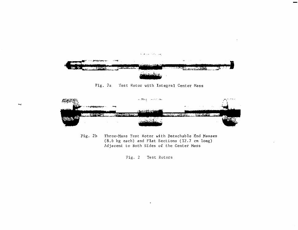
F i g . 2a Tes t Ro to r w i th In t eg ra l Cen te r Mass
F i g . 2b Three-Mass Test Rotor with Detachable End Masses ( 8 . 6 kg each) and Flat Sect ions ( 1 2 . 7 cm long) Adjacent to Both Sides of the Center Mass
F ig . 2 Tes t i io tors

Tab le 1
TEST COMBINATIONS OF MAJOR SHAFT DIAMETER AND END MASSES
Major Diameter End Masses ( 4 (kg) 6.51 Both 8 .6
6.51 Both 4.94
6.51
5.72
4.80
One 4.94 One 1.13
One 4.94 One 1 . 1 3
One 4.94 One 1 . 1 3
Figure 3 shows t h e e x p e c t e d t r e n d s f o r undamped t h i r d c r i t i c a l s p e e d s c a l c u l a t e d
f o r t h e r o t o r - b e a r i n g s y s t e m a t a r e p r e s e n t a t i v e , b u t c o n s t a n t , b e a r i n g s t i f f -
n e s s o f 2.4 x 10 N/m f o r v a r i o u s r a t i o s o f t h e d i m e n s i o n a c r o s s t h e f l a t s (F)
t o t h e o r i g i n a l r o t o r d i a m e t e r ( D ) . I t s h o u l d b e n o t e d t h a t t h e t h i r d c r i t i c a l
speed ment ioned here is a c t u a l l y t h e f i r s t a t w h i c h s i g n i f i c a n t b e n d i n g o c c u r s
' a n d , t h e r e f o r e , t h e f i r s t a t w h i c h f l e x u r a l a s y m m e t r y e f f e c t s c a n b e e x p e c t e d
t o i n f l u e n c e r o t o r d y n a m i c b e h a v i o r . T h e s e l e c t e d d e s i g n p o i n t i n d i c a t e s a
d i f f e r e n c e o f a p p r o x i m a t e l y 2,000 rpm be tween the c r i t i c a l (bending) speeds
t h a t t h e r o t o r w i l l e x h i b i t a b o u t t h e m a j o r a n d m i n o r s t i f f n e s s a x e s . The
d i f f e r e n c e i n la teral n a t u r a l f r e q u e n c i e s of 1 5 t o 20 p e r c e n t w a s e x p e c t e d t o
r e s u l t i n p r o n o u n c e d a n d d i s t i n c t i v e l y s e p a r a t e r o t o r - b e a r i n g r e s o n a n c e s .
7
F i g u r e s 4 and 5 p r e s e n t c r i t i c a l s p e e d maps f o r t h e m o d i f i e d r o t o r a b o u t i t s
maximum and minimum s t i f f n e s s a x e s , r e s p e c t i v e l y . S i n c e r o t o r w e i g h t i s
a f f e c t e d i n s i g n i f i c a n t l y t h r o u g h t h e m a t e r i a l r e m o v a l a t t h e f l a t s e c t i o n s ,
t h e r o t o r b e a r i n g s t i f f n e s s c u r v e s a n d t h e f i r s t a n d s e c o n d ( r i g i d b o d y )
c r i t i c a l speeds remain near ly unchanged.
The b e a r i n g s t i f f n e s s c u r v e f o r a p r e l o a d f a c t o r o f m = 0 . 3 is a p p l i c a b l e t o
t h e t e s t s e t u p . The e f f e c t o f i n c r e a s e d b e a r i n g s t i f f n e s s , a s i t might be
o b t a i n e d t h r o u g h p r e l o a d i n c r e a s e t o m = 0 . 5 , h a s b e e n i n c l u d e d i n t h e i n v e s t i g a -
t i o n a s a l i m i t i n g case.
8

0.95 0.90 0.85 0.80 0.75 0.70 0.65 0.60 F/ 0
Fig. 3 C a l c u l a t e d Undamped T h i r d C r i t i c a l S p e e d s For The Modi f i ed Tes t Rotor With F l a t S e c t i o n s
9

100,000 I I I I I 1
i B- FIRST CRITICAL SPEED C-SECOND CRITICAL SPEED
40,000 D-THIRD CRITICAL SPEED
80,000 A- BEARING RADIAL STIFFNESS (HORIZONTAL AND VERTICAL DIRECTIONS)
2ooo2 1000 1
2 4 8 I x lo7
J 1 ' 2
- A-aA + B
4
INDIVIDUAL BEARING RADIAL STIFFNESS,N/m I 1 I 1 I I I
I X lo4 2 4 I x lo5 2 4 INDIVIDUAL BEARING RADIAL STIFFNESS ,LB/IN
Fig. 4 Crit ic;11 Speed Map FOK F lex ib l e -Ro to r .Test Rig (Rotor With F l a t S e c t i o n s , C r i t i c a l S p e e d s A s s o c i a t e d With The Ro to r I n e r t i n Axis AA). *m i s t h e p r e l o a d r a t i o (1 - assembled c l ea rance /mach ined c l ea rance )
10

l00,000 I I I I
80,000- A- BEARING RADIAL STIFFNESS (HORIZONTAL AND VERTICAL DIRECTIONS)
5- FIRST CRITICAL SPEED C-SECOND CRITICAL SPEED l
INDIVIDUAL BEARING RADIAL STIFFNESS, N/m I I I I I I I
I x104 2 4 I x IO5 2 4 INDIVIDUAL BEARING RADIAL STIFFNESS LBAN
Fig . 5 C r i t i c a l Speed Map F o r F l e x i b l e - R o t o r T e s t Rig (Rotor With F l a t S e c t i o n s , C r i t i c a l S p e e d s A s s o c i a t e d With The Rotor I n e r t i a Axis BB) *m is t h e p r e l o a d r a t i o (1- assembled c l ea rance / machined clearance)

F i g u r e s 0 through 8 show the undamped rotor mode s h a p e s a t t h e f i r s & t h r c c
c r i t i c a l s p e e d s c a l c u l a t e d w i t h a bea r ing p r e l o a d EacLor rn = 0.3. The roLor
mode shapes ca l cu la t ed abou t t he ma jo r and minor i n e r t i a a x e s of the f l a t r o t o r
a r e v e r y similar a t a l l t h r e e c r i t i c a l s p e e d s . A s l i g h t l y i n c r e a s e d amount: of
bearing damping m a y , however, be expec ted a t t h e c r i t i c a l s p e e d s f o r the so f t
r o t o r a x i s from the small s h i f t i n n o d a l p o i n t s a t t h e t h i r d c r i t i c a l s p e e d .
C a l c u l a t i o n s o f t h e damped r o t o r a m p l i t u d e s a t t h e t h i r d c r i t i c a l s p e e d ( F i g -
u r e 9), o c c u r r i n g a t 8434 rpm a b o u t t h e r o t o r i n e r t i a a x i s BB and a t 10,763 rpm
f o r a x i s AA, i n d i c a t e l o w e r a m p l i t u d e s f o r t h e r e s o n a n c e o c c u r r i n g a t the lower
r o t o r s p e e d . The a m p l i t u d e r a t i o f o r t h e c r i t i c a l s a b o u t t h e two m u t u a l l y
p e r p e n d i c u l a r a x e s d o e s n o t a p p e a r e x c e s s i v e l y d i s t o r t e d ( c o n s i d e r i n g t h e
f requency d i f fe rence be tween the two) , ind ica t ing a moderate and thus acceptable
e f fec t o f bear ing damping a t t h e l o w e r t h i r d c r i t i c a l s p e e d .
F i g u r e s 10 through 12 p r e s e n t c a l c u l a t e d undamped r o t o r mode shapes a t t h e
f i r s t t h r e e c r i t i ca l s p e e d s w i t h a b e a r i n g p r e l o a d f a c t o r m = 0.5. A t t h e
h i g h e r b e a r i n g s t i f f n e s s e s w h i c h r e s u l t f r o m t h e i n c r e a s e d b e a r i n g p r e l o a d ,
t h e a d d i t i o n o f f l a t s e c t i o n s o n t h e r o t o r h a s a much s t r o n g e r e f f e c t upon t h e
d i f f e r e n c e i n mode shapes . Fo r t he l ower of t h e t h i r d c r i t i c a l s p e e d s , con-
s i d e r a b l e a m p l i t u d e s now exist a t the bea r ings , wh ich migh t g ive rise t o
cons iderable bear ing damping . S ince i t a l w a y s h a s b e e n o u r g o a l t o c r e a t e
least f a v o r a b l e c o n d i t i o n s f o r t h e b a l a n c i n g e x p e r i m e n t s , b e a r i n g s e t u p
c learances commensura te wi th a p r e l o a d f a c t o r o f m = 0.3 were s e l e c t e d .
I n i t i a l Test R e s u l t s
The test r e s u l t s r e p o r t e d i n t h i s s e c t i o n refer t o t h e test r o t o r w i t h t h e
i n i t i a l m a j o r d i a m e t e r o f 6.51 cm and var ious end masses, A t o t a l
o f t h r e e r o t o r c o m b i n a t i o n s were t e s t ed w i th t he ma jo r d i ame te r unchanged .
These combina t ions are l i s t e d as t h e f i r s t t h r e e cases i n T a b l e 1.
The f i r s t r o t o r d y n a m i c phenomenon encoun te red a t t h e i n i t i a l t e s t p h a s e was
c a u s e d b y g r a v i t a t i o n a l e x c i t a t i o n a n d o c c u r r e d when t h e r o t o r s p e e d w a s one-
h a l f o f t h e f i r s t b e n d i n g c r i t i c a l s p e e d c a l c u l a t e d f o r t h e l o w s t i f f n e s s a x i s
of t h e r o t o r . The o b s e r v e d v i b r a t i o n s h a d a frequency of twice t h e r o t o r

. "_ _ _ ~ " _ _ _ ~
I I I I I --"-- CALCULATED FOR ROTOR INERTIA AXIS A A -
CALCULATED FOR ROTOR INERTIA AXIS BB'
A-ROTOR MODE SHAPE AT 4873 RPM
B-ROTOR MODE SHAPE AT 4856 RPM
BEARING .2
b .O
\i ,, (K= 8.2 x IO7 N/m) -
\,&- L t - T= 47,000 LB/IN)
BEAFIINJ " I h4 I
0.2 (K = 8.2 x IO7 N l m ) - .4 -(K= 47,000 LB/IN)
=- .6
-.8 I
-I .o ROTOR SECTION I AT L I AND L, B
0 IO 20 30 40 50 60 70 80 90 100 11 1 1 I I I
ROTOR LENGTH-cm I
' 0 5 IO 15 20 25 30 35 40 I I I I I I I I
ROTOR LENGTH-IN Fig . 6 Undamped Rotor Mode Shape A t The F i r s t System C r i t i c a l Speed For Tes t Rotor W i t h F l a t
Sec t ions (Bea r ing P re load m = 0.3)

! z: I 0 I - I I-
. ., 0 w -I Lh.
1
I *o .8
".."-.-."I-."
--
"
CALCULATED FOR ROTOR INERTIA AXIS A B
CALCULATED FOR ROTOR INERTIA AXIS B B .2
, .o B-ROTOR MODE SHAPE AT 5044 RPM
I L I 1 I 1
BEARINGf. L*+ BEARING
(K= 8.2 x IO7 N/m) - * 2 - ( K = 8.2 x IO7 N / m ] I
-.a --:;:::I - ( K = 47,000 LB/IN)
-
r A@A ( 7 5 IN)
- (K = 47,000 LB/iN)-
-.6
-. 8
-7- 63.5 m m 1
"-
ROTOR SECTION -I .o AT L I AND L, 6
I I I I I
ROTOR LENGTH - cm 0 IO 20 30 40 50 60 70 80 90 100 I IO
I I I I I I I I
0 5 IO 15 20 25 30 35 40 I
ROTOR LENGTH -IN F i g . 7 Undamped Rotor Elode Shapes A t The Second C r i t i c a l Speed For Test Rotor With F l a t S e c t i o n s
(Bea r ing P re load Fac to r m = 0.3)
I .

1
-
-
-
-
I
-
-
-
1 1 1 1 1 1 1 1 I 0 IO 20 30 40 50 60 70 80 90 too I IO
I >
ROTOR LENGTH -cm
0- ' I
5 IO 15 20 25 30 35 40 I 1 I I II
ROTOR LENGTH-IN
.8
.o
A-ROTOR MODE SHAPE AT 10763 RPM
- " -8-ROTOR MODE SHAPE AT 8453 RPM CALCULATED FOR ROTOR INERTIA AXIS A A
CALCULATED FOR ROTOR INERTIA AXIS B 8
F i g . 8 Undamped Rotor Mode Shapes A t The Thi rd Sys tem Cr i t ica l Speed For Test Rotor With F l a t Sec t ions (Bear ing Pre load Fac tor m = 0.3)

1 3.5-
i t
( K A = 2.8 x IO7 N/m ) ( K A = 2.8 x 10⁷N/m]
(KB=2.1 x IO7 N / m ) (K,=2.1 x lO7N/m] (KA= ~60,000 L6/IN) \\
+FA -/ / ( K A= 160,000 LB/I N ]
(KB=120,000 LB/IN) I -
(K,B= 12OQOO LB/IN: A-ROTOR MODE SHAPE AT 10763 RPM
CALCULATED FOR ROTOR INERTIA AXIS A A MODE SHAPE AT 8434 RPM
CALCULATED FOR ROTOR INERTIA AXIS B B
-
0 10 20 30 40 50 60 70 80 90 IO0 I10 ROTOR LENGTH -cm
I I I I I I I I I 0 5 IO 15 20 25 30 35 40
ROTOR LENGTH-IN F i g . 9 Damped Rotor Amplitudes A t The Th i rd Sys t em Cr i t i ca l Speed For Test Rotor With F l a t S e c t i o n s
(Bea r ing P re load Fac to r rn = 0.3; In-Line , In-Phase Unbalance Conf igura t ion)

If CALCULATED FOR ROTOR INERTIA AXIS AA
CALCULATED FOR ROTOR INERTIA AXIS BB
A-ROTOR MODE SHAPE AT 6896 RPM
B-ROTOR MODE SHAPE AT 6845 RPM
I
ROTOR SECTION I I
0 IO 20 30 40 50 60 70 80 90 100 II ROTOR LENGTH-cm
I I I I I I I I 0 5 IO 15 20 25 30 35 40
I
ROTOR LENGTH-IN F i g . 10 Undamped Rotor Mode Shapes A t The F i r s t System C r i t i c a l Speed For Tes t Rotor W i t h F l a t
Sect ions (Bearing Preload Factor m = 0.5)

I .o
.8
.6
0 . * 4 t-
J LL w
.2
a .o a 0 t- -.2 G o z w * - 4 > !Z -.6
a -.8
-I .o
- J w
"- -.
1
1
<-ROTOR MODE SHAPE AT 7270 RPM
B-ROTOR MODE SHAPE AT 7216 RPM
-~
CALCULATED FOR ROTOR INERTIA AXIS A A
CALCULATED FOR ROTOR INERTIA AXIS B B I I I I
- L t" L2+ - I BEARING
I I ( K = 1.75 x IO7 N/m) - (K= 100,000 - (K = 100,000 LBAN)
(K = 1.75 x IO7 N/m)
t 1 1 !
e
" ROTOR SECTiON AT L I AND L, B
I i 0 IO 20 30 40 50 60 70 80 90 100 1
ROTOR LENGTH - cm 1 I I I I I I I
0 5 10 15 20 25 30 35 40 I
ROTOR LENGTH -IN F l g . 1 1 Undamped Rotor Mode Shapes A t The Second Critical Speed For Test Roto r K i t ' I I z : SecEiozs
__ (Bearing Preload Factor m = Mf- ~ ~-
-

CALCULATED FOR ROTOR INERTIA AXIS B B 0 IO 20 30 40 50 60 70 80 90 100 I IO
ROTOR LENGTH -cm 1 1 I I I I I I I
0 5 IO 15 20 25 30 35 40 ROTOR LENGTH -IN
~-
F i g . 1 2 Undamped Rotor Mode Shapes A t The Third System C r i t i c a l Speed For Test Rotor With F l a t Sect ions (Bearing Preload Factor m = 0.5)
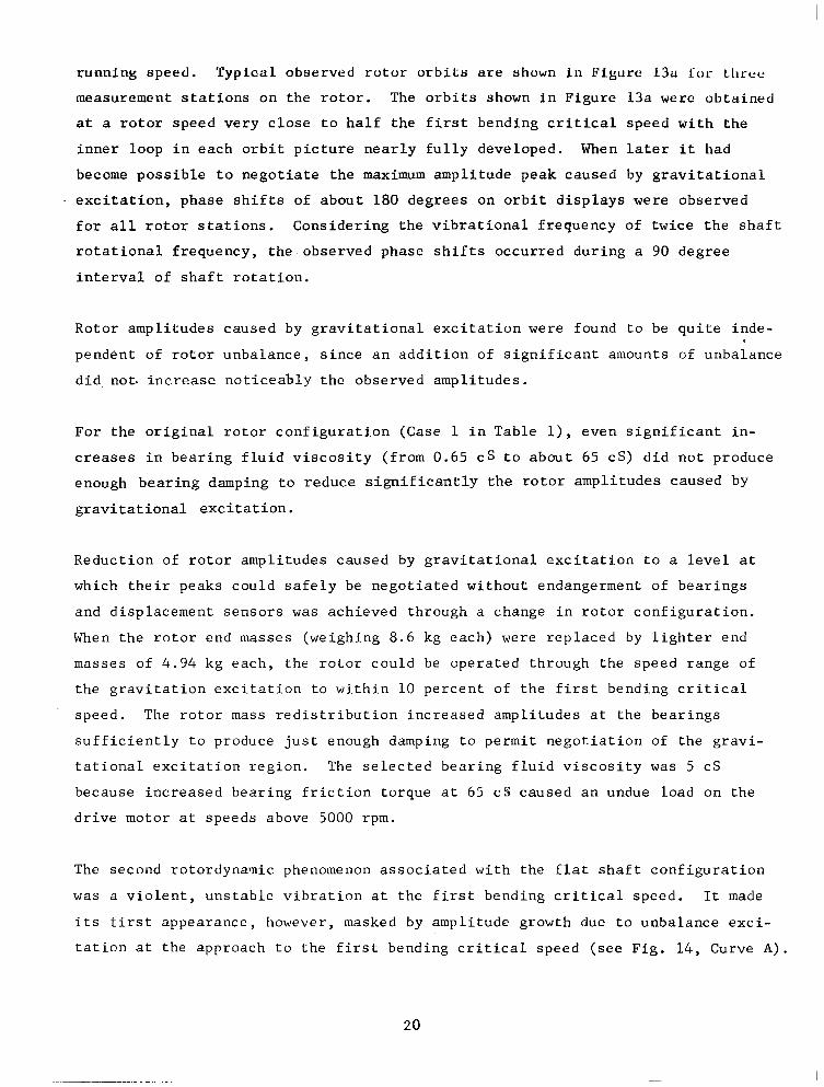
runn ing s p e e d . T y p i c a l o b s e r v e d r o t o r o r b i t s are shown in F igure 13u Lor Lllrcc
m e a s u r e m e n t s t a t i o n s o n t h e r o t o r . The o r b i t s shown i n F i g u r e 13a were o b t a i n e d
a t a r o t o r s p e e d v e r y c l o s e t o h a l f t h e f i r s t b e n d i n g c r i t i c a l s p e e d w i t h t h e
i n n e r l o o p i n e a c h o r b i t p i c t u r e n e a r l y f u l l y d e v e l o p e d . When l a t e r i t had
become p o s s i b l e t o n e g o t i a t e t h e maximum ampl i tude peak caused by g r a v i t a t i o n a l
- e x c i t a t i o n , p h a s e s h i f t s o f a b o u t 180 d e g r e e s o n o r b i t d i s p l a y s were observed
f o r a l l r o t o r s t a t i o n s . C o n s i d e r i n g t h e v i b r a t i o n a l f r e q u e n c y of t w i c e t h e s h a f t
r o t a t i o n a l f r e q u e n c y , t h e o b s e r v e d p h a s e s h i f t s o c c u r r e d d u r i n g a 90 degree
i n t e r v a l o f s h a f t r o t a t i o n .
Ro to r ampl i tudes caused by g r a v i t a t i o n a l e x c i t a t i o n w e r e f o u n d t o be q u i t e i n d e -
p e n d e n t o f r o t o r u n b a l a n c e , s i n c e a n a d d i t i o n o f s i g n i f i c a n t a m o u n t s o f u n b a l a n c e
did. not . increase n o t i c e a b l y t h e o b s e r v e d a m p l i t u d e s .
F o r t h e o r i g i n a l r o t o r c o n f i g u r a t i o n ( C a s e 1 i n T a b l e I), e v e n s i g n i f i c a n t i n -
c r e a s e s i n b e a r i n g f l u i d v i s c o s i t y ( f r o m 0 . 6 5 cs to abou t 65 cS ) d id no t p roduce
e n o u g h b e a r i n g d a m p i n g t o r e d u c e s i g n i f i c a n t l y t h e r o t o r a m p l i t u d e s c a u s e d by
g r a v i t a t i o n a l e x c i t a t i o n .
R e d u c t i o n o f r o t o r a m p l i t u d e s c a u s e d by g r a v i t a t i o n a l e x c i t a t i o n t o a l e v e l a t
w h i c h t h e i r p e a k s c o u l d s a f e l y be nego t i a t ed w i thou t endange rmen t o f bea r ings
and d i sp l acemen t s enso r s was achieved th rough a change i n r o t o r c o n f i g u r a t i o n .
When the ro tor end masses (weighing 8 .6 kg each) were rep laced by l i g h t e r e n d
masses of 4.94 k g e a c h , t h e r o t o r c o u l d be ope ra t ed t h rough t he speed r ange o f
t h e g r a v i t a t i o n e x c i t a t i o n t o w i t h i n 10 p e r c e n t o f t h e f i r s t b e n d i n g c r i t i c a l
speed . The r o t o r mass r e d i s t r i b u t i o n i n c r e a s e d a m p l i t u d e s a t t h e b e a r i n g s
s u f f i c i e n t l y t o p r o d u c e j u s t e n o u g h d a m p i n g t o p e r m i t n e g o r i a t i o n o f t h e g r a v i -
t a t i o n a l e x c i t a t i o n r e g i o n . The s e l e c t e d b e a r i n g f l u i d v i s c o s i t y was 5 CS
b e c a u s e i n c r e a s e d b e a r i n g f r i c t i o n t o r q u e a t 65 CS caused an undue load on the
d r i v e m o t o r a t speeds above 5000 rpm.
The second rotordyna-ic phenomenon a s s o c i a t e d w i t h t h e f l a t s h a f t c o n f i g u r a t i o n
was a v i o l e n t , u n s t a b l e v i b r a t i o n a t t h e f i r s t b e n d i n g c r i t i c a l s p e e d . It made
i t s f i r s t a p p e a r a n c e , h o w e v e r , masked by ampl i tude g rowth due t o unba lance exc i -
t a t i o n a t t h e a p p r o a c h t o t h e f i r s t b e n d i n g c r i t i c a l s p e e d ( s e e F i g . 14, Curve A ) .
20

I
S t a t i o n 1
S t a t i o n 4 S t a t i o n 5 One m a j o r d i v i s i o n e q u a l s a p p r o x i m a t e l y 0 .013 mm- R o t o r s p e e d = 4470 r p m
F i g . 1 3 a R o t o r O r b i t T r a c e s a t M e a s u r e m e n t S t a t i o n s 1, 4 , and 5
F ig . 13b T i m e S c a n S i g n a l a t S t a t i o n 1 w i t h a O n c e - p e r - R e v o l u t i o n R e f e r e n c e S i g n a l ( a b o v e )
F i g . 1 3 G r a v i t a t i o n a l E x c i t a t i o n of R o t o r w i t h 6.50 c m D i a m e t e r a t F l a t S e c t i o n
21

A p p r o a c h i n g t h e f i r s t c r i t i c a l s p e e d , t h e a m p l i t u d e c o n t r i b u t i o n f r o m u n b a l a n c e
cou ld be d ra s t i ca l ly r educed t h rough mul t ip l ane ba l anc ing , s o t h a t t h e r o t o r would
o p e r a t e w i t h o n l y a m i n i m a l a m p l i t u d e i n c r e a s e r i g h t up t o a speed which appeared
t o be t h e f i r s t b e n d i n g c r i t i c a l s p e e d . A t t h a t p o i n t , h o w e v e r , t h e a s y m m e t r i c
r o t o r e x h i b i t e d a s t e p jump i n a m p l i t u d e s t o wha t was . cons ide red a dangerous
l e v e l . An a m p l i t u d e p l o t o f t h i s o c c u r r e n c e i s shown i n F i g u r e 1 4 , C u r v e B.
There was n o i n d i c a t i o n d u r i n g a n y o f t h e s e a n d t h e f o l l o w i n g tes ts t h a t t h e
r o t o r c o u l d be a c c e l e r a t e d t h r o u g h t h i s r e g i o n o f h i g h a m p l i t u d e s , d e s p i t e
some i n a d v e r t e n t f o r a y s i n t o r a t h e r e x c e s s i v e r o t o r a m p l i t u d e s . C o n s e q u e n t l y ,
i t was d e d u c e d t h a t t h e o b s e r v e d s u d d e n a m p l i t u d e i n c r e a s e s weice indeed the
o n s e t o f i n s t a b i l i t i e s p r e d i c t e d t o o c c u r b e t w e e n t h e two b e n d i n g c r i t i c a l
s p e e d s a s s o c i a t e d w i t h t h e d i f f e r e n t s t i f f n e s s e s o f a r o t o r w i t h f l a t s e c t i o n s .
The f o l l o w i n g e f f o r t was, t h e r e f o r e , d i r e c t e d , f i r s t , a t f u r t h e r a t t e m p t s t o
i n c r e a s e r o t o r - b e a r i n g s y s t e m d a m p i n g t h r o u g h r o t o r mass r e d i s t r i b u t i o n ; a n d ,
f a i l i n g t h a t , a n a n a l y t i c a l a n d e x p e r i m e n t a l i n v e s t i g a t i o n o f t h e limits o f
r o t o r i n s t a b i l i t y o n s e t as a f u n c t i o n o f d i s s i m i l a r i t y b e t w e e n r o t o r s e c t i o n s
i n t h e two m u t u a l l y p e r p e n d i c u l a r a x e s .
Redes ign of Test Ro to r
The r e d e s i g n o f t h e t e s t r o t o r f o r i n c r e a s e d s t a b i l i t y a t a n d a b o v e t h e f i r s t
b e n d i n g c r i t i c a l s p e e d p r o c e e d e d i n two p h a s e s . I n t h e f i r s t p h a s e , r o t o r
mass d i s t r i b u t i o n was f u r t h e r c h a n g e d t h r o u g h s u b s t i t u t i o n o f o n e v e r y l i g h t
(1.13 kg) aluminum end mass f o r o n e o f t h e s t e e l end masses , and bea r ing f l u id
v i s c o s i t y was a g a i n i n c r e a s e d a b o u t t e n f o l d . N e i t h e r a c t i o n had t h e d e s i r e d
r e su l t s o f r e d u c i n g t h e i n s t a b i l i t y a m p l i t u d e t o a n e g o t i a b l e l e v e l . C o n s e -
q u e n t l y , r o t o r s t a b i l i z a t i o n was now a t tempted th rough a r e d u c t i o n i n t h e
r a t i o o f s t i f f n e s s e s i n t h e two r o t o r a x e s ( f l u i d v i s c o s i t y f o r a l l f o l l o w i n g
t e s t s was 5 cS) . Fo r mach in ing s impl i c i ty , t he ma jo r d i ame te r was p r o g r e s s i v e l y
reduced whi le the d imens ion across the f la t sec t ions remained unchanged. The
22

0.150 r h
I I 0.1251- Y I A - NBAkANCE ROTO AMP ITUDEI
B - OTORi AMPL TUDE AFTE [NE BILANJNG I34 1 7 1
I
1
_"
I I
+
3 4 5 6 7 8 9 IO II 12 13 14 15 1 ROTOR SPEED (RPM X
Fig. 14 Vert ical Rotor Ampli tudes a t Shaft Center - I n i t i a l C o n d i t i o n and Af te r One Balancing Run ( F i v e v e r t i c a l p r o b e s , r o t o r w i t h f l a t s e c t i o n s and two unbalances 4.94 kg each)

r e d u c t i o n s i n s h a f t d i a m e t e r a l s o p r o d u c e d a n i n c r e a s e d f l e x i b i l i t y o f t h e r o t o r
and a s l i g h t d r o p i n t h e f i r s t b e n d i n g c r i t i c a l s p e e d w i t h e a c h r e d u c t i o n i n
s h a f t d i a m e t e r .
To o b t a i n g u i d a n c e i n f i n d i n g w h a t r e d u c t i o n i n t h e m a j o r diameter, from 6.51 cm,
w o u l d b e n e c e s s a r y t o s t a b i l i z e t h e r o t o r , a n d w h a t t h e i n f l u e n c e of the inter- m e d i a t e v a l u e s of diameter would be upon the s t a t e o f s t a b i l i t y of the r o t o r , an
a n a l y s i s was c a r r i e d o u t . The a n a l y s i s , e n t i t l e d " S t a b i l i t y o f a Sha f t Wi th
F l e x u r a l Asymmetry" is g i v e n i n A p p e n d i x B. The r e s u l t s o f t h e a n a l y s i s show
t h a t , when running speed was s e t c l o s e t o o r b e t w e e n t h e two f i r s t f l e x u r a l
c r i t i c a l s p e e d s a s s o c i a t e d w i t h t h e two p r i n c i p a l axes, a p a i r o f r o o t s w o u l d
be o b t a i n e d f r o m t h e e q u a t i o n s o f m o t i o n f o r f r e e v i b r a t i o n o f t h e r o t o r , b o t h
of which would be synchronous . For one roo t the r ea l p a r t would be negat ive,
a n d f o r t h e o t h e r t h e real p a r t w o u l d b e p o s i t i v e . The l a t t e r i s a n u n s t a b l e
r o o t s i n c e i t w i l l grow r a t h e r t h a n d e c a y w i t h time.
The n a t u r e o f t h e r e s u l t s i s i l l u s t r a t e d g r a p h i c a l l y i n F i g u r e 15, where the
p o s i t i v e rea l p a r t r e f e r r e d t o a b o v e i s p l o t t e d a g a i n s t r o t o r s p e e d f o r d i f f e r e n t
v a l u e s o f m a j o r d i a m e t e r s ( w i t h c o n s t a n t d i s t a n c e m a i n t a i n e d a c r o s s t h e f l a t s ) .
For values of major diameter between 5 and 6.35 cm, an uns t ab le speed r ange i s
i n d i c a t e d w h e r e t h e w i d t h o f t h e s p e e d r a n g e a n d t h e p e a k v a l u e o f t h e r e a l
p a r t o f t h e r o o t (S) i n c r e a s e w i t h i n c r e a s i n g m a j o r d i a m e t e r . The i n d i c a t i o n
i s t h a t a s u f f i c i e n t d e c r e a s e i n m a j o r d i a m e t e r w o u l d s h r i n k t h e h e i g h t a n d
w i d t h o f t h e u n s t a b l e s p e e d r a n g e t o z e r o . I n t e r e s t i n g l y , t h i s d i m e n s i o n a l
c h a n g e a l s o s h i f t s t h e u n s t a b l e s p e e d r a n g e t o l o w e r s p e e d v a l u e s s i n c e t h e
o v e r a l l f l e x i b i l i t y o f t h e s h a f t i s i n c r e a s e d .
I n F i g u r e 16 , t h e r e l a t i o n s h i p b e t w e e n t h e maximum va lue o f t he real p a r t o f S
and major diameter D i s shown f o r two d i f f e r e n t mass d i s t r i b u t i o n s . I n one case
( t h e " o r i g i n a l " r o t o r w h i c h c o u l d o p e r a t e a b o v e t h e r e g i o n o f g r a v i t a t i o n a l
e x c i t a t i o n ) , t h e m a s s e s a t e i t h e r e n d are 4.94 kg . In t he s econd case, one of
the masses has been reduced to 1.13 kg - a change which changes the mode shape
o f t h e f l e x u r a l c r i t i c a l s p e e d s l i g h t l y , i n c r e a s i n g a m p l i t u d e at t h e b e a r i n g s
a n d i n c r e a s i n g t h e p o t e n t i a l f o r d a m p i n g . C l e a r l y , t h e l i g h t e r e n d mass a l l o w s
a s t a b L e r o t o r t o be a c h i e v e d w i t h a l a r g e r m a j o r d i a m e t e r , 4.80 cm as opposed
24

-. .
-
UNSTA,BLE
f l
F i g . 15 Stab i l i ty Ana lys i s - R e a l Part of Root v s Speed for Di f f erent Major Diameters
c

I60
I40
I20
IO0
80
60
40
20
01 0 I 2 3 4 5 6 7 IO I I 12
MAJOR DIAMETER - D ( cm ) STABLE
Fig. 16 S t a b i l i t y A n a l y s i s - Real Part of Synchronous Root versus Major Diameter (Distance Across F la t s - 4 . 4 8 cm)

t o 4.62 cm. However, even 4.80 cm re .presents on ly a s e v e n p e r c e n t d i f f e r e n c e
b e t w e e n m a j o r d i a m e t e r a n d t h e d i s t a n c e a c r o s s t h e f l a t s ; s u r p r i s i n g l y , s u c h a n
a p p a r e n t l y small a s y m m e t r y c a n d e s t a b i l i z e t h e r o t o r .
Table 2 p r e s e n t s a summary o f c a s e s e x a m i n e d f o r s t a b i l i t y o f r o t o r o p e r a t i o n
a b o v e t h e f i r s t b e n d i n g c r i t i c a l s p e e d . O n l y t h o s e r o t o r c o n f i g u r a t i o n s , which
could b e s a f e l y o p e r a t e d t h r o u g h the g r a v i t y - e x c i t e d c r i t i c a l s p e e d , were con-
s i d e r e d .
V e r i f i c a t i o n o f t h e s t a b i l i t y a n a l y s i s was o b t a i n e d c o n c u r r e n t l y w i t h b a l a n c i n g
expe r imen t s , when e a c h o f t h e r o t o r c o n f i g u r a t i o n s was balanced s o t h a t low
r o t o r a m p l i t u d e s w e r e o b t a i n e d e i t h e r r i g h t u p t o t h e s t a b i l i t y l i m i t , o r f o r
o p e r a t i o n t h r o u g h t h e f i r s t b e n d i n g c r i t i c a l s p e e d . B a l a n c i n g r e s u l t s a r e
d e s c r i b e d i n t h e n e x t s e c t i o n .
27

Rotor Conf igu ra t ion
Nurnbe r
1
2
3
4
Table 2
ROTOR CONFIGURATIONS AND CONDITIONS
Diarne t e r Across
F l a t s (cm)
4.48
4.48
4.48
4.48
Ma j o r Diameter
(Crn)
6.50
6 . 5 0
5 . 7 2
4.80
End Masses (kg)
Both 4.94
One 4.94 One 1.13
One 4.94 One 1.13
One 4.94 One 1.13
Condi t ion (Predic ted and
Observed)
Unstable
Unstable
Unstable
S t a b l e ( l i g h t l y damped)
Threshold of S t a b i l i t y P r e d i c t e d
9 200
9500
8800
"
Observed
9000
9300
8750
"
BALANCING RESULTS
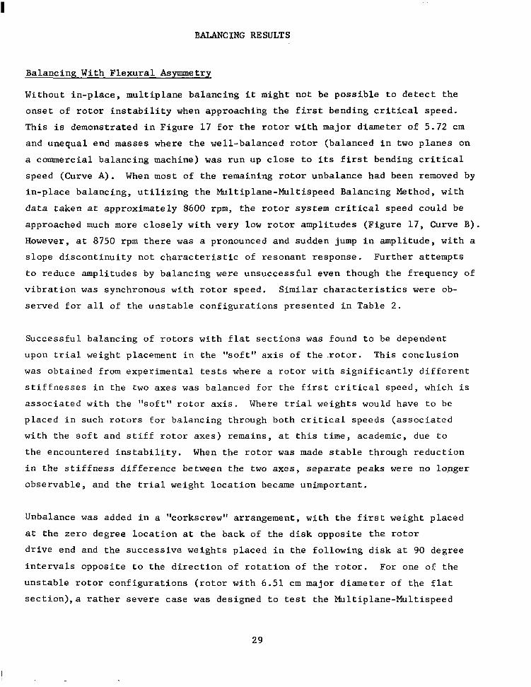
B a l a n c i n g W i t h F l e x u r a l Asymmetry
Wi thou t i n -p l ace , mu l t ip l ane ba l anc ing i t migh t no t be p o s s i b l e t o d e t e c t t h e
o n s e t of r o t o r i n s t a b i l i t y when a p p r o a c h i n g t h e f i r s t b e n d i n g c r i t i c a l s p e e d .
Th i s i s d e m o n s t r a t e d i n F i g u r e 1 7 f o r t h e r o t o r w i t h m a j o r d i a m e t e r o f 5 . 7 2 c m
a n d u n e q u a l e n d m a s s e s w h e r e t h e w e l l - b a l a n c e d r o t o r ( b a l a n c e d i n two p l a n e s o n
a commercial balancing machine) was r u n u p c l o s e t o i t s f irst bending c r i t i c a l
speed (Curve A ) . When mos t o f t he r ema in ing ro to r unba lance had been removed by
i n - p l a c e b a l a n c i n g , u t i l i z i n g t h e M u l t i p l a n e - M u l t i s p e e d B a l a n c i n g M e t h o d , w i t h
d a t a t a k e n a t approx ima te ly 8600 rpm, t h e r o t o r s y s t e m c r i t i c a l speed could be
approached much more c l o s e l y w i t h v e r y low ro to r ampl i tudes (F igu re 17 , Curve B).
However, a t 8750 rpm t h e r e was a pronounced and sudden jump i n a m p l i t u d e , w i t h a
s l o p e d i s c o n t i n u i t y n o t c h a r a c t e r i s t i c o f r e s o n a n t r e s p o n s e . F u r t h e r a t t e m p t s
t o r e d u c e a m p l i t u d e s by b a l a n c i n g were unsuccessfu l even though the f requency of
v i b r a t i o n was s y n c h r o n o u s w i t h r o t o r s p e e d . S i m i l a r c h a r a c t e r i s t i c s were ob-
s e r v e d f o r a l l o f t h e u n s t a b l e c o n f i g u r a t i o n s p r e s e n t e d i n T a b l e 2 .
S u c c e s s f u l b a l a n c i n g o f r o t o r s w i t h f l a t s e c t i o n s was f o u n d t o be dependent
upon t r ia l w e i g h t p l a c e m e n t i n t h e % o f t " a x i s o f t h e . r o t o r . T h i s c o n c l u s i o n
was ob ta ined f rom expe r imen ta l tes ts where a r o t o r w i t h s i g n i f i c a n t l y d i f f e r e n t
s t i f f n e s s e s i n t h e two axes w a s b a l a n c e d f o r t h e f i r s t c r i t i c a l s p e e d , w h i c h i s
a s s o c i a t e d w i t h t h e " s o f t " r o t o r a x i s . Where t r i a l weights would have to be
p l a c e d i n s u c h r o t o r s f o r b a l a n c i n g t h r o u g h b o t h c r i t i c a l s p e e d s ( a s s o c i a t e d
w i t h t h e s o f t a n d s t i f f r o t o r a x e s ) r e m a i n s , a t t h i s t i m e , academic, due t o
t h e e n c o u n t e r e d i n s t a b i l i t y . When t h e r o t o r w a s made s t a b l e t h r o u g h r e d u c t i o n
i n t h e s t i f f n e s s d i f f e r e n c e b e t w e e n t h e two a x e s , separate peaks were no longe r
obse rvab le , and t he t r ial we . igh t l oca t ion became un impor t an t .
Unbalance was added i n a " c o r k s c r e w " a r r a n g e m e n t , w i t h t h e f i r s t w e i g h t p l a c e d
a t t h e z e r o d e g r e e l o c a t i o n a t the back of t h e d i s k o p p o s i t e t h e r o t o r
d r i v e e n d a n d t h e s u c c e s s i v e w e i g h t s p l a c e d i n t h e f o l l o w i n g d i s k a t 90 degree
i n t e r v a l s o p p o s i t e t o t h e d i r e c t i o n o f r o t a t i o n o f t h e r o t o r . F o r o n e o f t h e
u n s t a b l e r o t o r c o n f i g u r a t i o n s ( r o t o r w i t h 6 . 5 1 c m m a j o r d i a m e t e r o f t h e f l a t
s e c t i o n ) , a r a t h e r s e v e r e c a s e w a s d e s i g n e d t o t e s t the Mul t ip lane-Mul t i speed
29

w 0
Fig . 17 Vertical Rotor Amplitudes a t S h a f t C e n t e r - I n i t i a l C o n d i t i o n and After One Balancing Run b y t h e L e a s t S q u a r e s P r o c e d u r e ( F o u r v e r t i c a l p r o b e s , r o t o r w i t h 5.72-cm d i a m e t e r a t f l a t s e c t i o n s a n d o n e aluminum end mass)

Balancing Method. The i n i t i a l r e s p o n s e a n d b a l a n c i n g r e s u l t s are p a r t i a l l y
documented i n F i g u r e 18. Shown are r o t o r a m p l i t u d e s a t t h e s h a f t m i d p o i n t sec-
t i o n of t h e i n t e n t i o n a l l y u n b a l a n c e d t e s t r o t o r . Even with a r e l a t i v e l y l a r g e
amount o f unbalance added to the ro tor , the f irst b a l a n c i n g r u n was s t i l l very
e f f e c t i v e ( C u r v e B) . Th i s w a s s u r p r i s i n g b e c a u s e , f o r a t least one r o t o r p l a n e ,
t h e " c o r k s c r e w " u n b a l a n c e d i s t r i b u t i o n p l a c e d s i g n i f i c a n t u n b a l a n c e s i n t h e
s t i f f axis of t h e r o t o r ; w h e r e a s i n f l u e n c e c o e f f i c i e n t s w e r e d e t e r m i n e d o n l y
f o r t r i a l w e i g h t s p l a c e d i n t h e s o f t r o t o r axis; r e s u l t a n t c o r r e c t i o n s were
e x p e c t e d t o b e i n s u f f i c i e n t . ( T h e i n c r e a s e d s t i f f n e s s o f t h e r o t o r i n t h e
" s t i f f " d i r e c t i o n t e n d s , of c o u r s e , t o r e d u c e t h e r o t o r d e f l e c t i o n e f f e c t d u e
t o u n b a l a n c e l o c a t e d t h e r e , t h u s e f f e c t i v e l y c o m p e n s a t i n g f o r t h e r o t o r s t i f f n e s s
v a r i a t i o n f o r a n g u l a r l o c a t i o n s b e t w e e n t h e s o f t a n d s t i f f a x e s . )
Only when the d i ame te r s a t t h e f l a t s e c t i o n s were f u r t h e r r e d u c e d t o 4.80 c m ,
which i s t h e l a r g e s t p r e d i c t e d d i a m e t e r a t wh ich t he ro to r wou ld r ema in s t ab le
a t t h e f i r s t c r i t i c a l s p e e d w i t h f l a t s e c t i o n s o f 4.48 cm, c o u l d t h e r o t o r
r e a d i l y be b a l a n c e d t o o p e r a t e a t and above the f i r s t c r i t i c a l speed (F igure 19) .
Curve A of Figure 19 i s f o r t h e r o t o r i n i t s i n i t i a l s t a t e of unbalance,and
Curves B and C show t h e r e s u l t s o f s u c c e s s i v e b a l a n c i n g o p e r a t i o n s . Nowhere on
t h e c u r v e s i s t h e r e t h e p r o n o u n c e d a n d s u d d e n i n c r e a s e i n a m p l i t u d e s o f F i g u r e
16, Curve B.
The r a p i d , b u t f i n i t e , a m p l i t u d e b u i l d u p a t the c r i t i c a l s p e e d i n d i c a t e s a ve ry
l i g h t l y damped s y s t e m , t h u s c o n f i r m i n g t h e p r e d i c t i o n f r o m t h e s t a b i l i t y a n a l y s i s
p r e s e n t e d i n T a b l e 2 . As a measure of the s y s t e m damping, the log decrement can
be de te rmined , approximate ly , f rom the shape of the response curve as fo l lows :
where f , f - are t h e f r e q u e n c i e s o f t h e p o i n t s a t wh ich t he ampl i tude equa l s
1 1 0 times t h e p e a k a m p l i t u d e a n d f n i s the r e sonan t f r equency (Hz) .
+
The r e a l p a r t o f t h e c o m p u t e d s y s t e m e i g e n v a l u e (A) c a n be c a l c u l a t e d as (-f )
t imes the log decrement . n
3 1

0. I50
0.125 z H Y
W
Y
a a
0.100 7 a n
Y
W
- J
I n a a 0
K 0.05C
C
A
i
\ I 1
i
7
L A r w
AFTEF
KuRE ONE
2 3 4 5 6 7 8 9 IO I I 12 13 14 16 ROTOR SPEED (RPM x IO-')
F i g . 18 V e r t i c a l R o t o r A m p l i t u d e s a t S h a f t C e n t e r - I n i t i a l R o t o r C o n d i t i o n ( C o r k s c r e w Unbalance Dis t r ibu t ion) and Af te r One Balancing Run by t h e L e a s t S q u a r e s P r o c e d u r e ( F i v e v e r t i c a l p r o b e s , r o t o r w i t h 6 . 5 1 cm Diameter a t F l a t Sec t ions and one aluminum end mass)

0. I50
0.125 I E Y
W
Y
a a $ 0.100
Y
W a
E a
U 0 & 0.050 (1:
0
I
I -
I I c. I
1 1 " A - UNBALANCED ROTOR AMPL 7 ROTOR AMPLITUDE i m
ONE BALANC NG RUU C - ROTOR BALANCED F3R OPE
AT AND ABOVE FIRST BEN[ CRITICAL SPE:ED
TUDE ,NE
lATlOF NG
I 2 3 4 5 6 7 8 9 IO I I 12 13 14 15 16
ROTOR SPEED (RPM X IO-?
Fig . 19 V e r t i c a l R o t o r A m p l i t u d e s a t S h a f t C e n t e r - I n i t i a l C o n d i t i o n a n d A f t e r One and Two Balancing Runs ( F o u r v e r t i c a l p r o b e s , r o t o r w i t h 4.80-cm diameter a t f l a t s e c t i o n s and one aluminum end mass)

From F i g u r e 19, Curve C y t h e s e c a l c u l a t i o n s y i e i d a log decrement o f 0.013
( e q u i v a l e n t t o a damping r a t i o o f 0.002) and the real pa r t o f t he complex e igen -
v a l u e , A = -1.62. When t h i s v a l u e f o r A is compared t o t h e p r e d i c t e d w o r s t
va lue o f +130 on Figure 16, a q u a n t i t a t i v e i n d i c a t i o n o f t h e m a r g i n a l n a t u r e o f
t h e s t a b i l i t y of t h i s c o n f i g u r a t i o n i s o b t a i n e d . The f a c t t h a t t h e M u l t i p l a n e
Balancing Method can ba l ance such a l i g h t l y damped r o t o r i s c o n f i r m a t i o n o f t h e
e f f e c t i v e n e s s of t he me thod unde r non- idea l cond i t ions .
Balancing With Resonant Probe Holders
P a r t o f t h e b a l a n c i n g e x p e r i m e n t s i n c l u d e d t h e u s e of f lex ib ly mounted probe
h o l d e r s as shown i n F i g u r e 20. The c a n t i l e v e r e d c o n s t r u c t i o n , wi th the p robe
holders hard mounted to the bear ing hous ings , was s e n s i t i v e t o c h a n g e s i n p r o b e
mass which a l lowed fo r ad jus tmen t s i n p robe ho lde r r e sonan t f r equency . The
b e a r i n g h o u s i n g v i b r a t i o n was used as t h e i n p u t e x c i t a t i o n f o r t h e f l e x i b l e
p r o b e h o l d e r . M a s s e s w e r e c l a m p e d t o t h e c a n t i l e v e r p r o b e s u p p o r t s u n t i l t h e i r
i n d i v i d u a l r e s o n a n t f r e q u e n c i e s w e r e c l o s e t o t h e c r i t i c a l s p e e d o f t h e r o t o r .
T h i s c o n d i t i o n was c r e a t e d t o a p p r o x i m a t e t h e e f f e c t s o f s t r u c t u r a l r e s o n a n c e s
o n t h e c a p a b i l i t y of t he ba l anc ing sys t em.
Three d i sp l acemen t s enso r s were moun ted t o t he f l ex ib l e p robe ho lde r s . These
t h r e e p r o b e s w e r e d i r e c t e d a t r o t o r s u r f a c e s o n e a c h o f t h e t h r e e r o t o r d i s k s .
An a c c e l e r o m e t e r was p l a c e d as c l o s e t o t h e d i s p l a c e m e n t s e n s o r as p o s s i b l e s o
t h a t t h e v i b r a t i o n o f t h e h o l d e r c o u l d be i s o l a t e d f r o m t h a t o f t h e s h a f t . F i g -
u r e 2 1 shows the t y p i c a l r e s o n a n c e c h a r a c t e r i s t i c o f t h e p r o b e h o l d e r s d u r i n g
t h e i n i t i a l t e s t r u n s w i t h a n u n b a l a n c e d r o t o r .
A l a r g e d i s t r i b u t e d u n b a l a n c e i n t h e r o t o r was s e l e c t e d t o c r e a t e h i g h v i b r a t i o n
w h i c h w o u l d e x c i t e t h e f l e x i b l e p r o b e h o l d e r s . When t h e r o t o r was i n i t i a l l y
a c c e l e r a t e d t o 6000 rpm, t h e e x c u r s i o n s of t h e d i s p l a c e m e n t s e n s o r , r e l a t i v e t o
t h e r o t o r c e n t e r d i s k , e x c e e d e d t h e l i n e a r r a n g e o f t h e i n s t r u m e n t a t i o n a b o v e
5800 rpm. The response of t h e r o t o r a t t h r e e s e n s o r l o c a t i o n s r e l a t i v e t o t h e
f l e x i h l y mounted displacement probes i s shown on Curve A o f F igu res 22 th rough
2.5. Since a l l t h r e e o f t l lcsc s c ’ n s o r s were ind iv idua l ly mounted , the r e so -
iuI1cLls 0 1 L I I L ~ i l c x i h l e p r o b e h o l d e r s are r e f l e c t e d i n t h e a m p l i t u d e c u r v e . The
r e sonance f r equenc ie s of t h e c a n t i l e v e r e d p r o b e h o l d e r s a r e c l e a r l y o b s e r v e d
34

Fig. 20 Tes t R i g w i th F l a t Sha f t and F l ex ib ly Mounted Probe Holders

10.0 -
7.5 -
5.0 -
2.5 -
2
I
!
i I I I
I I i
I 5260 RPM "-4 + ""
I I
-. -+
I I
i i ! -+"-I- " -7" -
t
1-
I I !
-I - ""
. .
"
i
"
I
3 4 5 6 7
ROTOR SPEED (RPM x lo3) 8 9 IO
Fig. 2 1 Vibra t ion Response of Mid-Plane Flexible Probe Holder During t h e I n i t i a l Running with a Dis t r ibu ted Unbalanced Rotor

.20c
. I 1 5
L Y .I50 Y
W a n I .I25 0 I- Y I
a w w .loo q n
W n 3 k .O?f a J
z a
-
g .ox k 0 a
.025
C
ROTOR SPEED (RPM x 16~)
1
3
Fig. 22 Vert ical Response a t t h e F r e e End Disk with the Probe Mounted i n a Flex ib le Bracket .

.200 r-
.175-
- 5 5 .150- Y
Y
W a n I .125- 0 t- Y I
a W n w .loo- a -
W L3 3 k .075" -I n z a 5 .ow- l- 0 a
.025 ,-
I
0 !-
A - FIRST RUN -HEAVY UNBALANCE B - I S T CORRECTION WEIGHTS C - 2ND CORRECTION WEIGHTS
0 9 IO I I
ROTOR SPEED WPM x 1 6 ~ ) 12 13 14 15
Fig . 23 Vert ica l Response a t t he Cen te r D i sk w i th t he P robe Mounted i n a F l e x i b l e B r a c k e t .

*200; I
.I751
c I z Y . I50/
a
1
Y
W Q I -125- 0 r- I Y a w . l o o n c
6 7
1- I
Probe Holder Resonanc i'
8
.- A - FIRST RUN -HEAVY UNBALANCE B - I ST CORREC,TION WEIGHTS - C - 2ND CORRECTION WEIGHTS
Fig. 24 Vert ical Response a t t h e F lex ib le Bracket .
ROTOR SPEED (RPM x 16~) Motor End D i s k with the Probe Mounted in a

d u r i n g t h e i n i t i a l a c c e l e r a t i o n a n d c a n s t i l l be i d e n t i f i e d f r o m a l l succes -
sive a m p l i t u d e c u r v e s o b t a i n e d a f t e r b a l a n c i n g .
To s t a y w i t h i n t h e l i n e a r r a n g e o f t h e d i s p l a c e m e n t i n s t r u m e n t a t i o n , a b a l a n c i n g
speed o f 5150 rpm, which i s less t h a n 70 p e r c e n t o f t h e r o t o r c r i t i c a l speed ,
w a s s e l e c t e d . It w a s a n t i c i p a t e d t h a t t h e r o t o r m i g h t be t o o f a r removed from
i t s n a t u r a l f r e q u e n c y t o o b t a i n m e a n i n g f u l i n f l u e n c e c o e f f i c i e n t s f o r t h e f i r s t
mode shape. A combina t ion o f da t a f rom the t h ree f l ex ib ly moun ted p robes and
one hard mounted probe were used for th i s exper iment . These p robes were a l l
v e r t i c a l . A s a r e f e r e n c e , v i b r a t i o n d a t a was a l s o t a k e n o n a s e c o n d s e t o f f o u r
p r b b e s w h i c h w e r e h a r d m o u n t e d d i s p l a c e m e n t s e n s o r s i n t h e h o r i z o n t a l p l a n e .
Each s e t o f p r o b e d a t a was u s e d i n d e p e n d e n t l y t o p r o v i d e a n a n a l y t i c a l c o m p a r i s o n
of hard mounted versus f lex ib ly mounted probes .
W i t h a p p l i c a t i o n o f t h e f i r s t s e t of c o r r e c t i o n w e i g h t s t o t h e r o t o r , b e a r i n g
h o u s i n g v i b r a t i o n s were reduced , t he reby r educ ing the e x c u r s i o n o f t h e f l e x i b l e
probe ho lders . Curves B of F i g u r e s 22 through 24 show t h e re la t ive r o t o r
r e s p o n s e t h r o u g h t h e f l e x i b l e p r o b e h o l d e r n a t u r a l f r e q u e n c i e s u p t o t h e f i r s t
r o t o r c r i t i c a l speed. Curve B s t i l l r e p r e s e n t s c o m p o s i t e v a l u e s o f f l e x u r e
v i b r a t i o n s a n d r o t o r a m p l i t u d e s , b u t i t a p p e a r s t h a t C u r v e E predominant ly
r e f l e c t s r o t o r v i b r a t i o n s e x c e p t f o r t h e n a r r o w s p e e d r e g i m e s a r o u n d t h e i n d i v i d u a l
p robe ho lde r r e sonances . S ince ampl i tudes above 7400 rpm were j udged t oo l a rge fo r
e i t h e r s a f e r o t o r o p e r a t i o n o r l i n e a r i n s t r u m e n t a t i o n r a n g e , t h e b a l a n c i n g p r o c e s s
was r e p e a t e d . The s e c o n d s e t o f c o r r e c t i o n w e i g h t s , b a s e d o n t h e 7400 rpm balarlc-
i n g s p e e d , was i n s t a l l e d , a n d t h e r o t o r was a b l e t o a c c e l e r a t e t h r o u g h t h e c r i t i c a l
speed as shown i n t h e r e s p o n s e C u r v e s C o f F igu res 22 t h rough 24.
A visua l compar ison of the responses f rom f lex ib ly mounted probes and hard
mounted probes in the same p l a n e s h o w e d t h a t p r o b e h o l d e r v i b r a t i o n c o n t r i b u t e s
s i g n i f i c a n t l y t o t h e o b s e r v e d o v e r a l l v i b r a t i o n s i g n a l . As measured by a c c e l -
e r o m e t e r s m o u n t e d n e x t t o t h e p r o b e , t h e v i b r a t i o n s i g n a l was n o t l i m i t e d t o
j u s t t h e i n t e g r a l r o t o r f r e q u e n c y , b u t c o n t a i n e d h i g h e r o r d e r f r e q u e n c i e s as
w e l l . F i g u r e 25 shows a compar ison of the hard mounted hor izonta l p robe and
the r e sonan t p robe fo r t he midp lane d i sk . No te t ha t t he f r equency con ten t
v a r i e s w i t h s p e e d . A t 7150 rpm, (Figure 2 5 a ) , the nonsynchronous components
caused by the r e sonan t p robe ho lde r were a m a j o r c o n t r i b u t o r t o t h e o v e r a l l
40
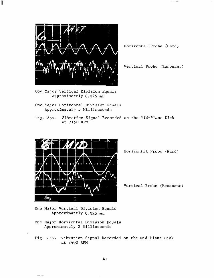
Horizontal Probe (Hard)
Vertical Probe (Resonant)
One Major Vertical Division Equals Approximately 0.025 mm
One Major Horizontal Division Equals Approximately 5 Milliseconds
Fig. 25a. Vibration Signal Recorded on the Mid-Plane Disk at 7150 RPM
Horizontal Probe (Hard)
Vertical Probe (Resonant)
One Major Vertical Division Equals Approximately 0.025 mm
One Major Horizontal Division Equals Approximately 2 Milliseconds
Fig. 25b. Vibration Signal Recorded on the Mid-Plane Disk at 7400 FPM
41

".
s i g n a l ; w h e r e a s , t h e s p e e d trace a t 7400 rpm shows v e r y l i t t l e p a r t i c i p a t i o n o f
h i g h e r f r e q u e n c i e s . I n F i g u r e 2 6 , s e v e r a l s u c c e s s i v e o r b i t s were superimposed
t o show t h e e f f e c t o f t h i s h i g h f r e q u e n c y r e s p o n s e o n t h e v i b r a t i o n as measured
f r o m t h e f r e e e n d d i s k ' s v e r t i c a l resonant p robe and hard mounted hor izonta l
probe.
The i n s t r u m e n t a t i o n u s e d f o r b a l a n c i n g s u c c e s s f u l l y s e p a r a t e s t h e n o n s y n c h r o -
nous v ib ra t ion f rom the synchronous v ib ra t ion componen t wh ich is needed fo r t he
ba l anc ing p rocess . Th i s had been we l l known i n t h e p a s t . The new a n d s i g n i f i -
c a n t f i n d i n g f r o m t h e s e e x p e r i m e n t s is t h e a b i l i t y o f t h e m u l t i p l a n e - m u l t i s p e e d
b a l a n c i n g m e t h o d t o r e d u c e u n b a l a n c e i n t h e r o t o r e v e n when l a r g e , e x t r a n e o u s l y
g e n e r a t e d , s y n c h r o n o u s v i b r a t i o n s h a v e b e e n a d d e d t o t h e s i g n a l s u s e d f o r b a l a n c i n g . However, i t m u s t b e r e m e m b e r e d t h a t t h e s e e x t r a n e o u s s i g n a l s , w h i c h o r i g i n a t e
f rom the p robe ho lde r s , are caused by unba lance - induced sha f t v ib ra t ion and ,
t h u s , are a d i r e c t f u n c t i o n o f i t .
T r i a l Weight Placement
A f t e r t h e r e s o n a n t p r o b e t e s t s h a d b e e n c o m p l e t e d , t h e r i g i d v e r t i c a l p r o b e s w e r e
r e i n s t a l l e d a n d a l l the unbalance and cor rec t ion weights were removed f rom the
r o t o r i n p r e p a r a t i o n f o r t h e t r i a l weight p lacement t e s t s . The "as is" r o t o r
was t h e n a c c e l e r a t e d t o a maximum speed of 7500 rpm b e f o r e e x c e e d i n g t h e v i b r a -
t i o n limits a n d , t h e r e f o r e , was n o t a b l e t o t r a v e r s e t h e c r i t i c a l s p e e d .
I n f l u e n c e c o e f f i c i e n t da t a was t a k e n a t 7400 rpm u s i n g t r ia l w e i g h t s p l a c e d a t
0 and 180 d e g r e e l o c a t i o n s o n t h e t h r e e b a l a n c i n g p l a n e s : t h e f r e e e n d , c e n t e r
p lane , and motor end d i sks . The c a l c u l a t e d c o r r e c t i o n w e i g h t s w e r e a p p l i e d t o
t h e r o t o r w h i c h t h e n s u c c e s s f u l l y p a s s e d t h r o u g h t h e c r i t i c a l speed . All
weigh t s were r emoved t o r e tu rn t o t he "as is" c o n d i t i o n a g a i n . The i d e n t i c a l
t r i a l weights were now p l a c e d a t t h e z e r o d e g r e e l o c a t i o n o n l y a n d i n f l u e n c e
c o e f f i c i e n t d a t a was a g a i n t a k e n a t 7400 rpm. When t h e c a l c u l a t e d c o r r e c t i o n
w e i g h t s f r o m t h i s s e t of i n f l u e n c e c o e f f i c i e n t s were p o s i t i o n e d o n t h e b a l a n c i n g
p l a n e s , t h e r o t o r was a g a i n a b l e t o g o t h r o u g h t h e c r i t i c a l s p e e d ; h o w e v e r , t h i s
t ime , t he v ib ra t ion l eve l s were somewha t h ighe r . F igu re 2 7 shows t he t yp ica l
v e r t i c a l r e s p o n s e o f t h e r o t o r f o r t h e "as is" cond i t ion (Curve A ) ; t h e 0 and
180 degree t r i a l weight placements (Curve B ) ; and t he ze ro deg ree on ly t r i a l
weights (Curve C ) .
42

One M a j o r D i v i s i o n E q u a l s Approximate ly 0.025 mm
F i g . 26 V i b r a t i o n O r b i t S i g n a l as Recorded From a R e s o n a n t V e r t i c a l P r o b e a n d H a r d M o u n t e d H o r i z o n t a l P r o b e o n t h e F r e e End D i s k a t 7130 RPM
43

.200r
-175-
c
5 Y .150-
a Y
w n 0 I- Y
1 .125-
I
s a w .loo- n
n L
W
3 k -075- n -I
I
5 .050- I- O
a
a .025 -
iL
A - -1
T k - FIR I" - COI
TR
r RUN 'ECTIO L WE1 ECIl.0 HTS 0
1 4 5 6 7 0 9 IO I I 12 13 14 15
ROTOR SPEED (RPM x 1 6 ~ ) 6
F i g . 27 Vertical Response a t the Motor End D i s k

S i n c e t h e i n f l u e n c e c o e f f i c i e n t s f r o m t h e z e r o d e g r e e t r i a l weight placements
seemed t o be l e s s a c c u r a t e i n b a l a n c i n g t h e r o t o r , t h e q u e s t i o n a r i s e s as t o
whether they could be used for a t r i m b a l a n c i n g o p e r a t i o n . V i b r a t i o n d a t a was
r eco rded a t 7400 rpm and new a d d i t i o n a l c o r r e c t i o n trim weights were determined
based on t he p rev ious ly de t e rmined s ing le t r i a l weight p lacement in f luence coef -
f i c i e n t s . The t y p i c a l r e s u l t s f r o m t h i s t e s t are shown i n F i g u r e 2 8 . The
r e s u l t a n t t r i m b a l a n c e d v i b r a t i o n a m p l i t u d e was extremely low, showing the capa-
b i l i t y f o r t r i m b a l a n c i n g e v e n i f t h e f i r s t b a l a n c e a t t e m p t was no t as a c c u r a t e
as cou ld be o b t a i n e d w i t h 0 and 180 degree t r i a l weight placements .
The r o t o r u n b a l a n c e d i s t r i b u t i o n was c h a n g e d s l i g h t l y a n d t h e t e s t was r e p e a t e d
t o v e r i f y t h e i n i t i a l f i n d i n g s . F o r b o t h t h e s i n g l e a n d d u a l t r i a l w e i g h t p l a c e -
m e n t b a l a n c i n g a t t e m p t s , t h e r o t o r was a b l e t o t r a v e r s e t h e c r i t i c a l s p e e d , b u t ,
a g a i n , r e s u l t s f r o m t h e s i n g l e t r i a l weight placement showed h i g h e r v i b r a t i o n .
The r o t o r - b e a r i n g s y s t e m i s p robab ly non l inea r because o f t he e f f ec t s o f j ou rna l
bear ing damping as a f u n c t i o n o f r o t o r v i b r a t i o n d i s p l a c e m e n t . T h i s n o n l i n e a r
e f f e c t i s h a n d l e d b e t t e r by two t r i a l we igh t p l acemen t s , s ince t he i n f luence
c o e f f i c i e n t s f r o m b o t h i n c r e a s e s a n d d e c r e a s e s i n v i b r a t i o n ( n o r m a l r e s u l t f r o m
0 and 180 degree t r i a l w e i g h t s ) a r e a v e r a g e d f o r u s e i n d e t e r m i n i n g c o r r e c t i o n
w e i g h t s .
T h i s means t h a t , i n g e n e r a l , a v e r a g e d i n f l u e n c e c o e f f i c i e n t s w i l l y i e l d more
c o n s i s t e n t l y a c c u r a t e c o r r e c t i o n w e i g h t s b e c a u s e t h e y a v e r a g e a n y p o t e n t i a l
e r r o r c r e a t e d by n o n l i n e a r e f f e c t s . H o w e v e r , t h i s d o e s n o t mean t h a t t h e s i n g l e
t r i a l weight placement i s n o t s a t i s f a c t o r y o r e v e n t h a t , a t t i m e s , i t w i l l no t
g ive a b e t t e r r e s u l t . I f t h e s i n g l e t r i a l weight placement happens to be 180
d e g r e e s o p p o s i t e t h e u n b a l a n c e p r o d u c i n g t h e v i b r a t i o n l e v e l , t h e n t h e s e i n f l u -
e n c e c o e f f i c i e n t s w i l l , i n f a c t , p r o b a b l y be more a c c u r a t e t h a n f o r t h e two tr ial
weight method. I n t h e f i n a l t e s t s , t h e r o t o r r e s p o n s e c h a r a c t e r i s t i c s were
m o d i f i e d a g a i n a n d r e s u l t s w i t h t h e s i n g l e t r i a l weight p lacement were ac tua l ly
b e t t e r t h a n w i t h t h e two we igh t s . F igu re 29 s h o w s t h e t y p i c a l r o t o r r e s p o n s e
f o r t h i s t e s t .
F i l t e r Bandwidth - V a r i a t i o n s
The f i n a l b a l a n c i n g e x p e r i m e n t s w e r e c o n d u c t e d w i t h v a r i o u s t r a c k i n g f i l t e r
bandwidths. I n s e p a r a t e t e s t s , 10 Hz, 25 Hz,and 50 Hz bandwidth f i l t e r s were
45

.200-
-175 -
- E v .150- Y a W n I .125- 0 k-
I
5 .owl- I- O a
-025 -
0 "
- 0
7 A
n 0 - x
Z S
a a. 1 5 0 I- I Y
e
Y
W
a w 4 n - w 0 3 ! I 3 n J
E a E 2 0 I- O a
I
C
i " 1
1-1- 3 4 5 1
7
' d- FIRS+ RUN E -CORRECTION WEIGH1 - WElG -IT ONL" L - I H!I~T BALAFRX w t f l
~
ROTOR SPEED (RPM x 16~)
F i g . 28 V e r t i c a l R e s p o n s e a t t h e Motor End Disk
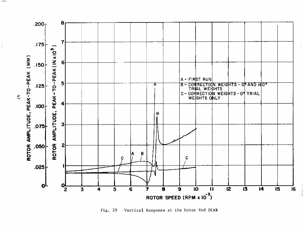
f
.200'
-115' i -
0 a
-025 0 t
-r 0 -
7 -
6.
5
4
3
2 -
I "- e 2 3 4
-7r -LL
6 7 L 9 II 12 13 14 15
ROTOR SPEED (RPM x 16~ ) I
F i g . 29 V e r t i c a l R e s p o n s e a t t h e P I o t o r End Disk

u s e d t o e l i m i n a t e v i b r a t i o n d a t a whose f r equency w a s somewhat d i f f e r e n t t h a n
t h e d i s c r e t e r o t a t i o n a l s p e e d . When the bandwidth becomes l a r g e , more non-
s y n c h r o n o u s v i b r a t i o n r e m a i n s w i t h i n t h e f i l t e r e d s i g n a l a n d t h e t o t a l s i g n a l
a m p l i t u d e i n c r e a s e s . Two t r i a l weight p lacements a t 0 and 180 degree on each
of t h e t h r e e b a l a n c i n g p l a n e s were u s e d f o r e a c h f i l t e r w i d t h . The r e s u l t a n t
c o r r e c t i o n w e i g h t s were a p p l i e d t o t h e r o t o r , a n d t h e t y p i c a l r e s p o n s e ( c e n t e r
d i s k ) i s shown f o r e a c h f i l t e r w i d t h i n F i g u r e 30. The r a w d a t a w o u l d i n d i c a t e
t h a t t h e 50 Hz f i l t e r , which allows the most amount of nonsynchronous vibra-
t i o n t o b e u s e d as d a t a , g a v e the b e s t r e s u l t s . It shou ld be no ted t hough t ha t ,
s i n c e t h e r o t o r i s highly undamped, small c h a n g e s i n a c c e l e r a t i o n r a t e c o u l d
h a v e p r o d u c e d t h e s e v a r i a t i o n s i n a m p l i t u d e . The i m p o r t a n t f a c t i s t h a t we
c o u l d s u c c e s s f u l l y t r a v e r s e t h e c r i t i c a l s p e e d f o r a l l t h r e e b a n d w i d t h f i l t e r s .
48

Y U w a 0 t- Y
. p a \ o w a
I
I
W D 2 t- - 1 a f a
.200
.I75
. I 50
.I 25
.loo
-075
.om
.025
0 3 4 5 6 7 0 9 IO II
ROTOR SPEED (RPM x 16~) 12 13 14
-I
Fig. 30 Ver t i ca l Response a t t he Cen te r Disk

GUIDELINES AND CRITERIA FOR LOCATION OF PLANES AND SENSORS
E n g i n e e r i n g f o r the use of m u l t i p l a n e b a l a n c i n g r e q u i r e s that locations b e
s e l e c t e d f o r balance p l a n e s a n d s e n s o r s ( p r o b e s ) . A r b i t r a r y s e l e c t i o n o f bal-
a n c i n g p l a n e o r p r o b e l o c a t i o n s c a n n o t be e x p e c t e d t o y i e l d opt imum balancing
e f f i c i e n c y . A s a f o r m a l i z e d a i d i n selecting opt imum ba lanc ing p lanes and
sensitive p r o b e l o c a t i o n s , an a n a l y s i s has been developed and is shown i n
Appendix A. In t h i s a n a l y s i s , the e f f e c t i v e n e s s o f a p a r t i c u l a r b a l a n c e p l a n e
c o n f i g u r a t i o n is q u a n t i f i e d i n terms of a pena l ty wh ich may be c a l c u l a t e d f r o m
a p a r t i c u l a r r o t o r as a f u n c t i o n o f t h e p l a n e l o c a t i o n s . In a d d i t i o n , a func-
t i o n which can be used to measure the s e n s i t i v i t y of a p a r t i c u l a r a r r a n g e m e n t
o f d i s p l a c e m e n t s e n s o r s i s sugges t ed i n Appendix A.
The p e n a l t y f u n c t i o n ( w h i c h s h o u l d be minimized) i s based on the amount of weight
which would have t o be added or removed to balance out a u n i t u n b a l a n c e d i s t r i b u -
t i o n f o r e a c h mode o f v i b r a t i o n w h i c h i s of concern . Two examples o f the use o f
t h i s p e n a l t y f u n c t i o n f o r a u n i f o r m r o t o r a r e p r o v i d e d i n a l a t e r s e c t i o n o f
t h i s r e p o r t .
The d e r i v a t i o n o f t h e p r o b e l o c a t i o n s e n s i t i v i t y f u n c t i o n i s more i n t u i t i v e t h a n
t h e f u n c t i o n d e v e l o p e d f o r b a l a n c e p l a n e l o c a t i o n s ; b u t , r e c o g n i z i n g t h i s s h o r t -
coming, i t c a n be e f f e c t i v e l y a p p l i e d .
Bo th € u n c t i o n s p r o v i d e g u i d a n c e t o t h e d e s i g n e r who i s f aced w i th t he p rob lem o f
s e l e c t i n g l o c a t i o n s f o r p l a n e s a n d s e n s o r s f o r m u l t i p l a n e b a l a n c i n g . They form-
a l i z e a process which m u s t o t h e r w i s e be b a s e d o n i n t u i t i o n . I n t h i s s e c t i o n o f
t h e r e p o r t , t h e u s e o f t h e s e f u n c t i o n s t o m e a s u r e t h e " q u a l i t y " o f p l a n e a n d
p r o b e l o c a t i o n s i s d e s c r i b e d a n d r e l a t e d t o t h e o v e r a l l p r o c e s s o f d e s i g n i n g
f o r mu1 t i p l a n e b a l a n c i n g .
F i g u r e 31 i s a f l o w c h a r t i l l u s t r a t i n g a n i d e a l s e q u e n c e t o f o l l o w i n t h e s e l e c -
t i o n o f l oca t ions fo r ba l ance p l anes and p robes .
The s t a r t i n g p o i n t f o r t h i s s e q u e n c e i s t h e s e t o f d r a w i n g s o f t h e r o t o r , i t s
bea r ings , and t he bea r ing suppor t s t ruc tu re . Based on t hese d rawings , s eve ra l
a c t i o n s a r e t a k e n : a dynamic model of the rotor i s prepared which can be
50

IDENTIFY PRACIICAL CONSTRAItiTS - ON PLANE/PROBE LOCATION t -
t ,
CALCUWLTE UNDANPED CRITICAL SPEEDS VS. BEARING STIFFNESS
"""
rc OF ROTOR PREPARE HODEL
- c
D F ~ W I N G S OF ROTOR, BEARINGS. I "- -
AND SITPORT STRLCTLXE
1 STIFRdESS I
1 ' CALCULATE STIFFNESS AND PLOT IDENTIFY LIKELY SUPERIMPOSE BEARING SELECT TENTATIVE
DAWING PROPEFSIES OF "c SHAPES CRITICAI. SPEED HAP BEARINGS AXD SCPPORTS
' STIFFNESS VALUES ON BALANCE PROBES = @ CRITICAL SPEEDS MODE - - LOCATIONS FOR
I AND PLAHES c
I I I
I I 1 1 I 3 CALCULATE DAMPED MODES:
a FREQUENCIES DECIDE ON WEIGHTING EIODAL VECTORS LOG DEC-
-0 FACTORS FOR MODES - USLYC TOLERANCE
INTEREST - OIJT-OF-PHASE WDALANCE HAGNITLlDE OUT SPEED RANGE OF
- IN-PHASE DETEWINE LIKELY -
1 CALCULATE RESPONSE PREPARE SEVERAL POSSIBLE - TO UNBALANCE THROUGH- - UNBALANCE DISTRIBUTIONS: SPECIFICATIONS,
RANDOH ORIEtiTATION - b I
Cn P
Fig . 31 M u l t i p l a n e B a l a n c i n g P r o c e d u r e f o r S e l e c t i o n o f P l a n e s a n d P r o b e s

7. n +
cn N
O P T I I r n
A - PROBE LOCATION
I AS APPROPRIATE:
ADJUST PLANElPROBE LOCATIONS . PROVIDE MORE NASS FOR R p l O V A L
USE DANPFD HODAL VECTORS TO CALCULATE OFTIHLM PROBEIPLANE LOCATIONS AND PENALTY ASSOCIATED
ACCOUNTING FOR CONSTRAINTS WITH BEST FEASIBLE LOCATION
- 1 I No
I 1
iPR0T P W l E S
DO SELECTED LOCATIONS OF PALANCE PLANES AND PROBES ACHIEVE:
I
.-. ACCEPTABLE PENALTY FUNCTIONS SATISFACTORY PREDICTED ANPLI-
FREEZE S n E C W
SPEEDS TO BALANCE . ACCEPTABLY SHALL N W E R OF
YES LOCATIONS TUDES AFTER BALANCING
REQUIKED .WSS RplOVAL LESS THAN THAT AVAILABLE FOR R P I O V A L SPEED
I I
C a C L - L A X ?XSW!:SE AT PROBE LJC.A7:3\5 :3 :SIT LWPALANCE
USE LEAST SQUARES B U C I N C
' @- AT LAC: iiLGCE PHASE LOCA- T:"S C!'.XA'I:L LXFLUENCE HL%tlIIZE PREDICTED PROBE <;::::<::Kj) AHPLITUDES
ANALYSIS TO CALCUUTE ?- CORRECTION E I G H T S TO
-
Fig. 31 ( S h e e t 2)

ana lyzed by a v a i l a b l e t o o l s f o r c r i t i c a l s p e e d , damped n a t u r a l f r e q u e n c y , a n d
u n b a l a n c e r e s p o n s e p r e d i c t i o n ; t h e b e a r i n g s a n d t h e i r s u p p o r t s t r u c t u r e a r e
a n a l y z e d t o d e t e r m i n e t h e s t i f f n e s s a n d d a m p i n g a s s o c i a t e d w i t h t h e r o t o r SUS-
p e n s i o n a n d t h e v a r i a t i o n o f s t i f f n e s s a n d d a m p i n g w i t h s p e e d ; t h e m a n u f a c t u r i n g
and ass .embly to le rances a re ana lyzed to de te rmine the amount by w h i c h t h e r o t o r
c e n t e r o f g r a v i t y may be o f f s e t f r o m t h e c e n t e r o f r o t a t i o n a t v a r i o u s p o i n t s
a l o n g t h e r o t o r ; t h e a s s o c i a t e d u n b a l a n c e m a g n i t u d e i s c a l c u l a t e d ; a n d t h e c o n -
s t r a i n t s w h i c h may impose themselves upon se lec t ion of ba lance p lane and probe
l o c a t i o n s a r e i d e n t i f i e d .
Once a good t h e o r e t i c a l m o d e l o f t h e r o t o r i s e s t a b l i s h e d , i t i s f i r s t u s e d t o
make undamped c r i t i c a l s p e e d p r e d i c t i o n s . C r i t i c a l s p e e d s s h o u l d be c a l c u l a t e d
ove r a w i d e r a n g e o f b e a r i n g s t i f f n e s s e s , i n c l u d i n g t h e l i k e l y r a n g e o f s t i f f -
n e s s v a l u e s . A s a minimum, t h e s p e e d r a n g e i n v e s t i g a t e d f o r c r i t i c a l speeds
should go beyond the l ike ly opera t ing speed ranges . The c r i t i c a l s p e e d i n f o r -
ma t ion i s c o n v e n i e n t l y p r e s e n t e d as a map o n w h i c h v a r i a t i o n o f c r i t i c a l s p e e d
w i t h s t i f f n e s s i s p l o t t e d . The v a r i a t i o n o f b e a r i n g s t i f f n e s s e s w i t h s p e e d i s
super imposed on th i s map a n d t h e p o i n t s o f i n t e r s e c t i o n o f b e a r i n g s t i f f n e s s
l i n e s w i t h c r i t i c a l s p e e d l i n e s i n d i c a t e t h e l i k e l y r e s o n a n t s p e e d s . One com-
p l i c a t i o n i s t h a t , w i t h u n e q u a l s t i f f n e s s e s i n t h e v e r t i c a l and h o r i z o n t a l
d i r e c t i o n s , t h e r e a r e two d i s t i n c t i n t e r s e c t i o n s b e t w e e n t h e b e a r i n g s t i f f n e s s
l i n e s a n d e a c h c r i t i c a l s p e e d l i n e . I n t h i s w a y , two f i r s t c r i t i c a l s p e e d s ,
two s e c o n d c r i t i c a l s p e e d s , e t c . , c a n be i d e n t i f i e d .
The mode s h a p e s o f t h e r o t o r f o r t h e s u p p o r t s t i f f n e s s v a l u e s a t t h e l i k e l y
r e sonan t speeds shou ld t hen be p l o t t e d . T h e s e mode shapes p rovide the mos t
i m p o r t a n t s i n g l e p i e c e o f i n f o r m a t i o n i n g u i d i n g t h e s e l e c t i o n o f b a l a n c i n g
p l anes and p robes . I f one ba l anc ing p l ane i s p r o v i d e d f o r e a c h mode t h a t t h e
r o t o r m u s t p a s s t h r o u g h , a n d i f t h e p l a n e a s s o c i a t e d w i t h e a c h mode i s l o c a t e d
a t , o r v e r y c l o s e t o , t h e p o i n t o f maximum a m p l i t u d e f o r Ehe mode, t h e n a
r e a s o n a b l e s e t of p l a n e l o c a t i o n s i s a s s u r e d . F o r r o t o r b e a r i n g s y s t e m s w i t h
u n e q u a l b e a r i n g s u p p o r t s t i f f n e s s e s , it may be worthwhile a t t h i s s t a g e i n t h e
d e s i g n t o u s e t h e mode s h a p e c o r r e s p o n d i n g t o t h e a v e r a g e s t i f f n e s s ; t h i s s h a p e
i s u n l i k e l y t o d i f f e r a p p r e c i a b l y f r o m t h e s h a p e a t e i t h e r p r e c i s e s t i f f n e s s
v a l u e .
53

I n t h i s way, t e n t a t i v e o r p r e l i m i n a r y l o c a t i o n s f o r b a l a n c e p l a n e s c a n be
s e l e c t e d and t he p re l imina ry p robe l oca t ion shou ld co r re spond c lose ly t o t he
s e l e c t e d p l a n e l o c a t i o n s . T h e s e s e l e c t i o n s a r e t e r m e d p r e l i m i n a r y o r t e n t a t i v e ,
s ince t hey mus t now be a d j u s t e d t o a c c o u n t f o r p r a c t i c a l c o n s i d e r a t i o n o f s u c h
f a c t o r s as where probes can be mounted; where there i s a n u n i n t e r r u p t e d p r o b e
t a r g e t of s u f f i c i e n t d i d t h ; w h e r e t r i a l weights c 'an be a t tached; and where metal
c a n be removed o r a d d e d t o i m p l e m e n t t h e r e q u i r e d b a l a n c i n g c o r r e c t i o n s . It i s
l i k e l y t h a t t h e s e c o n s t r a i n t s w i l l cause some a d j u s t m e n t i n t h e s e l e c t e d l o c a -
t i o n s ; t h e d e s i g n e r s s h o u l d b e i n t e r e s t e d i n t h e i n f l u e n c e o f t h e s e a d j u s t m e n t s
o n t h e e f f e c t i v e n e s s o f t h e b a l a n c i n g p r o c e s s .
Evalua t ion of P lane-Probe Loca t ions Us ing Modal A n a l y s i s " .~
The f i r s t e v a l u a t i o n e m p l o y s m o d a l a n a l y s i s m e t h o d s t o d e t e r m i n e a pena l ty func -
t ion (which should be minimized) t o be a s s o c i a t e d w i t h t h e se t of b a l a n c e p l a n e s ;
Appendix A d e s c r i b e s t h e a n a l y s i s . I n summary, f o r e a c h m a j o r mode of concern
a normalized sum o f t he we igh t s , Sn, t o c o r r e c t a u n i t modal unbalance is
c a l c u l a t e d :
where i s t h e maximum n o r m a l i z e d a m p l i t u d e a t a n y p k n e l o c a t i o n of the n th mode ' s forward whi r l vec tor .
max
W
'n c o r r e c t i o n w e i g h t d i s t r i b u t i o n r e q u i r e d t o b a l a n c e o u t is t h e c o n t r i b u t i o n i n t h e p t h b a l a n c e p l a n e t o t h e
a u n i t modal component of unbalance f o r t h e n t h mode.
S i n c e , t o a c h i e v e t h e same s t a t e of b a l a n c e , a p o o r s e l e c t i o n o f b a l a n c e p l a n e s
w i l l r e q u i r e more we igh t t o be added t han a good s e l e c t i o n , t h e o b j e c t i v e is t o
minimize S f o r e a c h mode of concern. n
54

The a n a l y s i s oE Appendix A r e q u i r e s t h a t t h e number of p l a n c s , I n , be e q u a l LO
the number of modes, n. Usually i t i s convenient t o m e t t h i s c o n s t r a i n t . The
condi t ions under which i t may be p o s s i b l e t o b a l a n c e e f f e c t i v e l y w i t h o u t m e e t i n g
t h i s c o n s t r a i n t a n d t h e way t h e a n a l y s e s c a n be u s e d i n t h i s c a s e w i l l s h o r t l y
be d i s c u s s e d . F i r s t , h o w e v e r , i t i s wor th d i scuss ing t he add i t iona l s t eps neces -
s a r y t o implement t h i s a n a l y s i s .
E s s e n t i a l t o t h e a n a l y s i s i s the de t e rmina t ion o f t he damped modes o f v i b r a t i o n
o f t h e r o t o r - b e a r i n g s y s t e m . The r e q u i r e d i n p u t s t o t h e c a l c u l a t i o n are t h e
dynamic r o t o r m o d e l a n d t h e s t i f f n e s s a n d d a m p i n g c h a r a c t e r i s t i c s o f t h e bear-
ings and bear ing suppor ts . Given these inputs , the complex e igenvalues o f the
sys t em a re de t e rmined , up t o and beyond f r e q u e n c i e s i n t h e r a n g e o f i n t e r e s t .
A method of determining complex eigenvalues i s d e s c r i b e d i n [ 4 ] . The complex
e igenva lue cons i s t s o f two q u a n t i t i e s , h and cun ( i t s r e a l and imaginary par t s ) .
wn i s t h e damped na tu ra l f r equency , and h i s the growth exponent, from which
the log decrement 6 n (= -2rr h /cu ) can be c a l c u l a t e d . 6n m e a s u r e s t h e e f f e c t i v e
system damping for the nth mode and , wi th h n o f o rde r 1 .5 or above, a n e g l i g i b l e
c o n t r i b u t i o n t o t h e r e s p o n s e i s t o be expec ted f rom tha t mode.
n
n
n n
Assoc ia t ed w i th each complex e igenva lue is a n e i g e n v e c t o r w h i c h d e f i n e s t h e
mode o f v i b r a t i o n i n terms o f f o u r q u a n t i t i e s a t e a c h s t a t i o n o f t h e r o t o r .
T h e s e q u a n t i t i e s are the ho r i zon ta l and ve r t i ca l i n -phase componen t s o f d i s -
p l acemen t and t he ho r i zon ta l and ver t ica l out-of-phase components of disnlace-
m e n t . F o r t h e p r e s e n t a n a l y s i s , e a c h e i g e n v e c t o r is b roken i n to a forward
c i r c u l a r w h i r l v e c t o r and a b a c k w a r d c i r c u l a r w h i r l v e c t o r , s u c h t h a t t h e
e l l i p t i c a l o r b i t a t a n y s t a t i o n is t h e sum of the forward and backward
c i r c u l a r w h i r l c o m p o n e n t s . I n a d d i t i o n , t h e a d j o i n t v e c t o r ( c ) t o t h e
f o r w a r d w h i r l v e c t o r (< ) is de te rmined . G iven t hese quan t i t i e s , t he ca l cu la -
t i o n o f S c a n p r o c e e d , w i t h t h e f o l l o w i n g q u a l i f i c a t i o n s .
n
n
n
- I f t h e b e a r i n g s are n o t i s o t r o p i c , t h e r e w i l l b e two damped n a t u r a l f r e q u e n c i e s
a s s o c i a t e d w i t h e a c h b a s i c v i b r a t i o n mode of t h e r o t o r ( s l i g h t d i f f e r e n c e s w i l l
ex is t be tween t h i s pa i r o f modes , bu t t he two shou ld no t be r ega rded as
d i s t i n c t modes f o r b a l a n c i n g p u r p o s e s - t h e d i s t r i b u t i o n o f p l a n e s w h i c h i s
good f o r o n e mode o f t h e p a i r w i l l b e g o o d f o r t h e o t h e r ) . A choice mus t be
made t o select only one of e a c h p a i r a n d t h e b e s t c h o i c e is t h e mode w i t h t h e
55

smaller l o g d e c r e m e n t , s i n c e t h i s is l i k e l y t o c o n t r i b u t e more s t r o n g l y t o t h e
r o t o r r e s p o n s e .
D e s i r a b l y , t h e r e s h o u l d b e a b a l a n c e p l a n e f o r e a c h d i s t i n c t mode through and
up t o which the r o t o r is r e q u i r e d t o r u n s m o o t h l y . T h i s s i t u a t i o n w i l l norm-
a l l y b e t h e r e s u l t o f t h e t e n t a t i v e p l a n e s e l e c t i o n s a l r e a d y made on t h e b a s i s
of t h e undamped mode s l o p e s . Some p o s s i b l e e x c e p t i o n s are cons ide red a s fo l lows :
( a ) Number o f p l a n e s less t h a n ~ t h e o r d e r o f - t h e - hig_he.st mode ~~ t o - be balanccd through.
I n g e n e r a l , a r o t o r c a n b e b a l a n c e d t h r o u g h t h e h i g h e s t o r d e r c r i t i c a l s p e e d
w i t h f e w e r p l a n e s t h a n t h e h i g h e s t o r d e r o n l y i f some o f t h e i n t e r m e d i a t e
modes are well-damped and, thereby, show a c c e p t a b l e r e s o n a n t a m p l i t u d e s w i t h -
o u t b a l a n c i n g . The degree of damping of each mode ca,n be judged from i t s l o g
decrement, 6 and , as a r u l e of thumb, t h e p l a n e a s s o c i a t e d w i t h a p a r t i c -
u l a r mode may b e d r o p p e d o n l y i f t h e l o g d e c r e m e n t f o r t h a t mode exceeds 1 . 5 . n '
To i m p l e m e n t t h e a n a l y s i s i n t h i s case t h e h e a v i l y damped modes whose :influ-
ence is b e i n g n e g l e c t e d m u s t b e d r o p p e d e n t i r e l y f r o m t h e a n a l y s i s so t h a t
t h e number of modes a c t u a l l y c o n s i d e r e d s t i l l matches the number o f p l a n e s .
(b) Number o f p l a n e s g r e a t e r t h a n t h e o r d e r o f t h e h i g h e s t mode whose i n f l u e n c e is t o b e b a l a n c e d .
I n t h i s case, t h e r e are planes which are redundant. However, the mechanics
of the ana lys i s can be implemented , p rovided tha t the number and order o f
modes c o n s i d e r e d i n t h e a n a l y s i s are i n c r e a s e d t o m a t c h t h e number o f p l anes .
I n t h i s case, t h e p e n a l t y f u n c t i o n s a s s o c i a t e d w i t h t h e h i g h e r m o d e s , w h i c h
are i n t r o d u c e d t o make t h e a n a l y s i s w o r k , n e e d n o t i n f l u e n c e t h e p l a n e
s e l e c t i o n .
" -. - -. -
( c ) Number o f p l a n e s e q u a l s t h e number of modes whose i n f l u e n c e is t o b e ba l anced ou t bu t some o f t he modes a r e m u c h less impor t an t (heav i ly damped) t h a n o t h e r s . ~- _c"" ~ - .
I f t h i s s i t u a t i o n e x i s t s , t h e p e n a l t y f u n c t i o n s a s s o c i a t e d w i t h t h e
wel l -damped modes should be g iven reduced weight ing in se lec t ion of
56

t h e p l a n e l o c n t i o n s . A s shown i n t h e Appendix, a mngnif i ca t ion F;~c:tor
c a n b e i d e n t i f i e d as a f u n c t i o n of t h e log decrement .
, T h i s f a c t o r may be conven ien t ly u sed as t h e w e i g h t i n g f a c t o r . One
way o f u s i n g t h i s
o f t he no rma l i zed
f u n c t i o n is t o g e n e r a t e a n a v e r a g e w e i g h t e d sum, S ,
c o r r e c t i o n w e i g h t s f o r a p l a n e c o n f i g u r a t i o n :
-
- Qn 'n s = 5 Qn
The q u a n t i t y , S, r e p r e s e n t s a s i n g l e t h e o r e t i c a l m e a s u r e o f t h e b a l a n c e ~~
p l a n e l o c a t i o n q u a l i t y . S has a minimum p o s s i b l e v a l u e of 1 a l t h o u g h , f o r
a p a r t i c u l a r p r o b e and number of modes of conce rn , t he minimum v a l u e may
be g r e a t e r t h a n 1. The combina t ion of ba lance p lane loca t ions which min i -
mizes S may. be cons idered as the optimum. The use of 2 o f f e r s c o n v e n i e n c e
as a s ing le measu re o f p l ane l oca t ion qua l i t y bu t mus t be u s e d w i t h g r e a t
c a r e a n d n e v e r w i t h o u t c o n s i d e r i n g t h e i n d i v i d u a l f u n c t i o n s S f o r e a c h
i n d i v i d u a l mode of importance.
-
n
Exper i ence mus t be e s t ab l i shed be fo re f i rm ru l e s fo r accep tab le va lues o f
S and 3 a r e e s t a b l i s h e d . I n R e f e r e n c e 3 , ex tens ive demons t r a t ions o f
s u c c e s s f u l b a l a n c i n g of a f l e x i b l e r o t o r t h r o u g h f o u r c r i t i c a l s p e e d s w e r e
p r e s e n t e d . A p p l i c a t i o n o f t h e s e b a l a n c e p l a n e l o c a t i o n c r i t e r i a f o r t h i s
r o t o r showed t h a t S , S2, S3 , and S were 1 7 , 11 , 2, and 26 p e r c e n t h i g h e r
t h a n t h e minimum, r e s p e c t i v e l y . The s u c c e s s o f t h i s c o n f i g u r a t i o n s u g g e s t s
t h a t s u c h d e v i a t i o n s are a c c e p t a b l e .
n
4
An e v a l u a t i o n of the p r o b e l o c a t i o n s is p o s s i b l e i n terms of P ( a q u a n t i t y
to be maximized) where: n
57

n i s t h e mode number, and Sn a m )
is t h e n o r m a l i z e d a m p l i t u d e , a t t h e mth p robe , o f the forward 6- ~~ n
c i r c u l a r whi r l m o d a l v e c t o r f o r the nth mode. In words , P measures n t h e a v e r a g e s e n s i t i v i t y o f t h e m e a s u r e m e n t s y s t e m t o a m p l i t u d e s o f t h e
nth mode. N o t e t h a t i ts use does no t impose a r e q u i r e m e n t t h a t t h e
number of probes match the number of modes considered.
Evalua t ion of P lane-Probe Loca t ions Us ing Balanc ing S imula t ion
A complementary eva lua t ion of the comple te p lane-probe combina t ion can be
performed by means of a s imula t ed ba l anc ing s equence . A s a s t a r t i n g p o i n t ,
o n e o r m o r e u n b a l a n c e d i s t r i b u t i o n s s h o u l d b e s e l e c t e d o n t h e b a s i s of t h e
l i ke ly unba lance magn i tudes p rev ious ly de t e rmined f rom manufac tu r ing and
a s sembly t o l e rances . Us ing va lues of bea r ing s t i f fnes s and damping wh ich
v a r y a p p r o p r i a t e l y w i t h s p e e d , t h e r e s p o n s e o f t h e r o t o r - b e a r i n g s y s t e m t o t h e
s e l e c t e d u n b a l a n c e a t a r a n g e o f s p e e d s o f i n t e r e s t i s c a l c u l a t e d u s i n g a
f l e x i b l e r o t o r u n b a l a n c e r e s p o n s e a n a l y s i s . U n l e s s a v e r y low level of un-
b a l a n c e h a s b e e n s e l e c t e d , t h e r o t o r w i l l ' b e u n a b l e t o p a s s t h r o u g h t h e f i r s t
s i g n i f i c a n t c r i t i ca l s p e e d w i t h o u t e x c e e d i n g limits imposed by one o r more of
b e a r i n g s , seals, d a m p e r s , w h e e l t i p c l e a r a n c e s , p r o b e c l e a r a n c e s . a n d , a t h i g h
o r d e r c r i t i c a l s p e e d s , s h a f t s t r e s s e s .
A t a speed where the f i r s t c r i t e r i o n s t a r t s t o a p p r o a c h i t s lirnit ( s a y w i t h i n
25 pe rcen t ) , t he i n f luence on ampl i tude a n d phase ang le , a t each probe , o f a
un i t unba lance a t each ba lance p lane , should be c a l c u l a t e d ( u s i n g t h e r o t o r
u n b a l a n c e r e s p o n s e a n a l y s i s ) . T h i s s e t o f c a l c u l a t i o n s p r o v i d e s i n f l u e n c e
c o e f f i c i e n t s f o r t h a t s p e e d . U s i n g t h e l e a s t s q u a r e s b a l a n c i n g m e t h o d , t h e
r e q u i r e d c o r r e c t i o n w e i g h t s i n t h e b a l a n c e p l a n e s t o m i n i m i z e a m p l i t u d e s a t t h e
p r o b e s a r e c a l c u l a t e d . T h e s e c o r r e c t i o n w e i g h t s a r e a p p l i e d a n d t h e r e s p o n s e
t o t h e r e s u l t a n t u n b a l a n c e d i s t r i b u t i o n as a func t ion o f speed i s r e c a l c u l a t e d .
The r o t o r i s now l i k e l y t o t r a v e r s e t h e f i r s t c r i t i c a l s p e e d w i t h o u t e x c e e d i n g
any of the l imi t s . I f no t , t he p rocedure m u s t be r e p e a t e d a t a s p e e d c l o s e r
t o t h e f i r s t c r i t i c a l s p e e d w h i l e s t i l l s a t i s f y i n g t h e s e limits. When the
r o t o r c a n t r a v e r s e t h e f i r s t c r i t i c a l s p e e d , t h e p r o c e d u r e is a g a i n r e p e a t e d
a t t h e n e x t c r i t i c a l s p e e d of s i g n i f i c a n c e . I n t h i s w a y , i f a n a d e q u a t e a r r a y
58

of ba lance p lanes has been provided , the ro tor can be balanced through a l l
c r i t i c a l s p e e d s i n t h e o p e r a t i n g r a n g e .
T h i s a n a l y t i c a l s e q u e n c e p r o v i d e s a c h e c k o n t h e s e l e c t i o n of b a l a n c e p l a n e s .
However, w i t h o u t m o d i f i c a t i o n , i t d o e s n o t t r u l y p r o v i d e a check on t h e s e l e c -
t i o n o f p r o b e l o c a t i o n s . The i n f l u e n c e c o e f f i c i e n t s and response ampl i tudes
c a n be c a l c u l a t e d t o h i g h a c c u r a c y w h e r e a s t h e r e q u i r e d m e a s u r e m e n t s are
l i m i t e d , i n p r a c t i c e , by t h e p r o b e s e n s i t i v i t y . F o r a g i v e n e l e c t r o n i c p r o b e
r e s o l u t i o n , e f f e c t i v e p r o b e s e n s i t i v i t y c a n be i n f l u e n c e d by p r o b e l o c a t i o n
r e l a t i v e t o t h e n o d e a n d a n t i n o d e l o c a t i o n s o n t h e r o t o r . Near an t inodes , where
a m p l i t u d e c h a n g e s a r e l a r g e r , b e t t e r p r o b e s e n s i t i v i t y c a n b e o b t a i n e d . To
p r o v i d e a check on p robe l oca t ions , i t wou ld be necessa ry t o s imu la t e a g i v e n
p r o b e s e n s i t i v i t y by l i m i t i n g t h e p r e c i s i o n w i t h i n w h i c h t h e r e s p o n s e a m p l i t u d e s
a r e c a l c u l a t e d s o t h a t e r r o r s i n t h e i n f l u e n c e c o e f f i c i e n t s a n d l e v e l o f u n b a l -
ance response ampl i tude are i n d u c e d . I f t h e c a l c u l a t i o n p r e c i s i o n i s made t o
c o r r e s p o n d t o t h e p r o b e r e s o l u t i o n , t h e e r r o r w i l l be c o n s i s t e n t i n m a g n i t u d e
w i t h t h e e r r o r s i n t r o d u c e d i n t a k i n g a c t u a l m e a s u r e m e n t s i n a ba lanc ing sequence .
S i n c e t h i s b a l a n c i n g s i m u l a t i o n p r o c e d u r e is more unwieldy than the o p t i m i z a t i o n
u s i n g t h e c r i te r ia S S , and P i t s h o u l d b e u s e d as a c h e c k r a t h e r t h a n as
p a r t o f t h e o p t i m i z a t i o n l o o p .
- n ' n'
Tab le 3 summar izes the in format ion provided by t h e e v a l u a t i o n s d e s c r i b e d a b o v e .
Tab le 3
SUMMARY OF INFORMATION OBTAINED DURING SELECTION OF
BALANCE PLANES AND PROBES
Analysis- - ". . Used. . In fo rma t ion P rov ided
Undamped Cri t ical Speeds 0 Reasonab le Se l ec t ion o f P l anes and Probes based on Mode Shapes
Damped N a t u r a l F r e q u e n c i e s 0 I d e n t i f i c a t i o n o f U n i m p o r t a n t Modes 0 Q u a n t i f i e d O p t i m i z a t i o n Criteria
f o r P r o b e a n d P l a n e S e l e c t i o n
Unbalance Response and Least 0 Checks on P lane Se lec t ion Squa res Ba lanc ing

As shown, the undamped c r i t i c a l mode shapes a n d t h c p r a b t i c a l c o n s L r a i n L s i m -
posed by t h e r o t o r c o n E i g u r a t i o n c a n be used to make a r c a s o n a b l c s e l e c t i o n 0 1
b a l a n c e p l a n e a n d p r o b e l o c a t i o n s , i f i t i s e n s u r e d t h a t the maximum a m p l i t u d e f o r
each mode i s c l o s e l y c o v e r e d by a p r o b e ; t h a t a d i s t i n c t b a l a n c e p l a n e e x i s t s
f o r e a c h mode; a n d t h a t t h e l o c a t i o n o f t h e p l a n e a s s o c i a t e d w i t h e a c h mode i s
nea r the l o c a t i o n of maximum a m p l i t u d e f o r tha t mode. The cri teria based on damped
modes p r o v i d e t w o v a l u a b l e e x t e n s i o n s t o t h e undamped a n a l y s i s : f i r s t , t h e unimpor-
t a n t modes a r e i d e n t i f i e d by t h e e x i s t e n c e o f a l a r g e log decrement (above 1 . 5 ) ;
a n d s e c o n d , t h e s e n u m e r i c a l c r i t e r i a a l l o w a v a l u e t o be p l aced on any s e t of
p robe or p lane loca t ions and show t h e c h a n g e i n t h i s v a l u e w i t h v a r y i n g l o c a t i u n s .
Ba lanc ing s imula t ion u s ing unba lance r e sponse p red ic t ions and a l e a s t s q u a r e s
ba lanc ing procedure i s a va luable check which a d d s c r e d i b i l i t y t o t h e s e l e c t i o n
of ba lance p lane and probe loca t ions .
I n t h e f o l l o w i n g r e p o r t s e c t i o n , n u m e r i c a l e x a m p l e s a r e p r e s e n t e d of t he eva lua -
t i on p rocedures wh ich u se damped modes. Examples of the balancing s imulat ion
p r o c e d u r e a r e n o t p r e s e n t e d , b u t a f u l l d e m o n s t r a t i o n o f t h e p r o c e d u r e m a y be
found i n R e f e r e n c e 1 2 .
60

-
EVALUATION OF C R I T E R I A FOR BALANCE PLANE AND SENSOR LOCATIONS
I n t h i s s e c t i o n , u s e o f t h e c r i t e r i a d e v e l o p e d i n A p p e n d i x A a n d d i s c u s s e d i n
t h e p r e v i o u s s e c t i o n i s d e m o n s t r a t e d . I n t h e . f i r s t e x a m p l e , t h e c r i t e r i a a r e
used t o p r e d i c t optimum ba lance p l ane and p robe l oca t ions fo r a u n i f o r m f l e x i b l e
s h a f t on r i g i d s u p p o r t s ; a n d i n t h e s e c o n d , a u n i f o r m f l e x i b l e s h a f t o n f l e x i b l e
damped b e a r i n g s i s c o n s i d e r e d .
Uniform Shaft ~ ... on Rigid Supports
When t h e r o t o r s y s t e m i s f r e e o f damping and gyroscopic moments can be ignored ,
t he ana lys i s o f Append ix A can be s imp l i f i ed cons ide rab ly . The e igenvalues be-
come pure ly imag ina ry (pu re f r equenc ie s ) and t he mode shapes become p l a n a r
( r e a l ) . A l s o , t h e a d j o i n t f u n c t i o n s are i d e n t i c a l t o t h e modal funct ions, and
Equat ion (A-47) r educes t o :
Furthermore, when t h e s u p p o r t s are i s o t r o p i c , t h e w h i r l o r b i t s are c i r c u l a r
s u c h t h a t 5 becomes real .
To i l l u s t r a t e , a u n i f o r m s h a f t , s u p p o r t e d i n r i g i d b e a r i n g s a t t h e e n d s , i s
cons ide ied . This i s e q u i v a l e n t t o t h e c l a s s i c a l s i m p l y s u p p o r t e d beam f o r
which the resonant f requencies and mode shapes are g iven by (Reference 1).
and,
where M = UP- is t h e t o t a l mass of t h e s h a f t , a n d R is t h e l e n g t h .
61

Balance P lane Loca t ion - Three Mode Ralanc ing
If t h e r o t o r is t o b e b a l a n c e d f o r t h r e e c r i t i c a l s p e e d s , i t w i l l b e assumed
t h a t o n e c o r r e c t i o n p l a n e , P l a n e No. 2 , is i n t h e m i d d l e (- = 2 ) ; w h i l e t h e
o t h e r two p l a n e s , P l a n e Nos. 1 and 3 , are symmet r i ca l ly l oca t ed a round t he
middle :
z2 1 R
- = z3 z1 R
1" R
S e t t i n g 5 = - z1 Equat ion ( A - 5 4 ) y i e l d s : 1 E '
U
W W
U 1 u2 U 3
w31 32 33
1 2 3 -
W W -" U U U
which is r e a d i l y s o l v e d t o g i v e :
W W 11- 1 2 u1 u2
W 1 3 -
u3
W 23
3 U
W 33
u3
5,)
W W 21- 22 u1 u2
s i n ( 2 n 5 1 1 s i n ( 2 n 5 ) 1
0 2 s i n ( 2 n 5 ) s i n ( 3 n 1
62

A s cl is less than -, the normalized sum, of t he modal cor rec t ion weights
becomes (Equation A-55):
1 2 'n 9
1 + l s i n ( 3 ~ 5-1 I - -
I sin(.rr 5 ) + s in (3n 5 ) 1 1
1 + sin(.rr 5 )
sin(.rr 5,) + sin(3.rr 5,) s3 - - 1
The r e s u l t s are p l o t t e d i n F i g u r e 32 where t h e a b c i s s a is < and t h e o r d i n a t e
g ives S1, S2 and S The optimum p lane l oca t ion is seen to be : c . ~ = 0.25
whi le the acceptab le range is approximately between 0.1 and 0.3.
1
3'
The s l o p e d i s c o n t i n u i t y i n t h e c u r v e f o r mode 1 arises because of the require-
ment, i n t h e a n a l y s i s of Appendix A, t h a t any combination of weights to balance
out modal u n b a l a n c e f o r t h e f i r s t mode makes no con t r ibu t ion t o t he s econd o r
t h i r d modal unbalances.
Reference to the mode s h a p e s f o r t h e f i r s t t h r e e modes (Figure 33) shows, f i r s t ,
that weights added to change the unbalance of mode 1 w i l l be most e f f e c t i v e i f ,
f o r a l l planes, they are a l l a t t h e same angular loca t ion . Thus , i f weights
added i n p l a n e s 1 and 3 were 180' opposed t o t h e w e i g h t t o b e added i n p l a n e 2 ,
the required magnitude of the plane 2 weight would be much h i g h e r t h a n i f a l l
t h r e e were a t t h e same angu la r l oca t ion .
The second mode shape shows t h a t , whenever the weights in planes 1 and 3 are
equa l , a t the same angular loca t ion and e q u i d i s t a n t f rom the shaf t cen ter , they
w i l l be s e l f - c a n c e l l i n g f o r mode 2 whatever and wherever the plane 2 weight is .
For t he t h i rd mode t h i s is not the case ; weights a t t h e same angu la r l oca t ion
i n p l a n e s 1 and 3 are add i t ive and , i f p l anes 1 and 3 are c lose t o t he midd le ,
i t is clear t h a t t h e only way to avoid changing the exc i ta t ion of t h e t h i r d mode
when b a l a n c i n g t h e f i r s t mode i s to pu t t he p l ane 2 weight 180" removed from
t h e 1-3 weight - the s i tua t ion which w a s p r e v i o u s l y i d e n t i f i e d as c a l l i n g f o r
63

0 0.1 0.2 0.3 0.4 0.5
Coordinate of Plane No. 1
F i g . lii I n f l u e n c e o f P l a n e 1 on l\;oru1alized Sun1 of C o r r e c t i o n \ Je i .gh ts for Uniform Shaft on Rigid Bearings and Three C r i t i c a l s .
64

P l a n e 2
L""_" Range for P l a n e . . 1 Range for P l a n e 3
Mode 1
Fig . 33 Mode Shapes For Uniform S h a f t In Rig id Suppor ts
65

a l a rge we igh t i n p l ane 2 . I f , al ternatively, p lanes 1 and 3 are c l o s e t o t h e
ends, the plane 2 cor rec t ion can be a t t h e same angu la r l oca t ion and no t exc i t e
t h e t h i r d : a t t h e l o c a t i o n of p lanes 1 and 3 , one-third of the shaf t length f rom
e i t h e r end ( see a r rows fo r mode 3 , Figure 33) is the po in t where mode 3 changes
s ign and , t he re fo re , where t h i s s i t ua t ion reverses. This change of s i g n is
r e f l e c t e d by t h e s l o p e d i s c o n t i n u i t y i n t h e mode 1 p l o t of Figure 3 2 . This p lo t
s ays , c l ea r ly , t ha t p l anes 1 and 3 shou ld no t be t oo c lose t o t he cen te r of t he
s h a f t .
Se l ec t ion of Probe Locations - Three Mode Balancing
The c r i t e r i o n f o r e v a l u a t i n g t h e s e n s i t i v i t y of a pa r t i cu la r p robe conf igu ra t ion
i s :
I n a p p l y i n g t h i s t o b a l a n c i n g o f t h e f i r s t t h r e e modes of t he un i fo rm sha f t i n
r i g i d s u p p o r t s , i t is assumed that one probe is loca ted a t t h e c e n t e r of t he
s h a f t (- = 0.5) and t h a t t h e number of probes equals the number of modes. The
two off-center probes are located symmetrically. Thus, P is evaluated as a
func t ion of t he d i s t ance of probes 1 and 3 from the ends o f the shaf t .
Z R
n
Based on equat ion 15 , the fo l lowing express ions may be wr i t t en :
(18)
These Values for the probe qual i ty funct ions have been plot ted in Figure 34 a s a
funct ion of - . I t may be s een t ha t , t o ma in ta in good s e n s i t i v i t y f o r a l l
t h r e e modes, i t is necessary to keep probes 1 and 3 in the region of 0 .25 t imes
the sha f t l eng th from each end. I f i t were no t poss ib le to p lace these p robes
exac t ly a t the 0 .25 locat ion, i t would be p re fe rab le t o s h i f t them towards the
ends of the shaf t than towards the center , s ince the mode 3 s e n s i t i v i t y f u n c t i o n
f a l l s o f f s h a r p l y as the 1-3 probe locat ion moves f u r t h e r from the end.
Z 1 R
66

4
3 . 5
3
2 . 5
2
1 . 5
1
. 5
0
0 0.1 0.2 0.3 0.4 0.5
Coordinate of Probe No. 1
F i g . 34 E f f e c t of Probe 1 and 3 Location on Probe S e n s i t i v i t y F u n c t i o n s for Uniform Shaft on Rigid Bearings
67

An i n t e r e s t i n g r e s u l t may b e i n f e r r e d from Figure 34 i n t h a t a s ing le p robe at
t he cen te r of t h e s h a f t g i v e s maximum s e n s i t i v i t y f o r b o t h modes 1 and 3 . Ap-
p a r e n t l y ¶ a l l t h r e e modes could be accurately sensed by a p a i r of probes, one
a t t h e c e n t e r and one a t .25 times the length f rom one end. A s noted previous-
l y ¶ i t is n o t a requirement of the probe opt imizat ion procedure that the num-
b e r of probes match the number of modes t o b e b a l a n c e d a n d , i n t h i s case, t h e
third probe could be regarded as redundant; i ts use s imply ensures tha t the
balancing procedure has more broadly based information to operate on.
Balance Plane Location -Four Mode Balancing
I f t h e r o t o r is to be ba lanced th rough four c r i t i ca l speeds , i t w i l l be assumed
tha t t he co r rec t ion p l anes are located symmetrically around the middle:
z z " 3 - 1" 2 9, R
z . z - "
4 1 - 1" R R
z 1 z S e t t i n g 5 = - and c 2 1 R
- - - t h e r e s u l t i n g modal correct ion weights can be
determined from Equation ( A - 5 4 ) as:
68

The normalized sums of t he modal cor rec t ion weights are computed from Equation
(A-55), and t h e r e s u l t s are shown in F igures 35 th rough 3 9 . Each graph appl ies
t o a f ixed pos i t i on o f p l anes 1 and 4 ( < = - 1 z1 = 0.05, 0.125, 0.167, 0.25, R
and 0 .333) , whi le the pos i t ion o f p lane 2 (and, hence, of plane 3) var ies as
given by t h e a b s c i s s a . Each graph contains four curves , g iving the normalized
sums of t he modal cor rec t ion weights .
It i s found t h a t t h e optimum l o c a t i o n s of planes 1 and 2 are 0.167 and 0.375,
r e spec t ive ly , bu t cons ide rab le dev ia t ions are acceptable .
A s w i t h t h e t h r e e mode ba lanc ing r e su l t s , t he re are s l o p e d i s c o n t i n u i t i e s i n
Figure 35 through 39 - t h i s t i m e f o r t h e f i r s t two modes. Similar arguments to
those deve loped for the th ree mode case can be used to explain these discon-
t i n u i t i e s .
Uniform - . S h a f t i n F l e x i b l e , Damped Bearings
A s a second example, consider a uniform shaf t wi th overhung ends, supported in
two i d e n t i c a l b e a r i n g s . The b e a r i n g c o e f f i c i e n t s are:

100
90
80
70
60
50
40
30
20
15
10
9
8 7
6
5
4
3
2
1
I 1 Plane
1 Plane Plane P lane
2 3 Coordinate
0.2 0 . 3 0.4
Coordinate of Plane No. 2
0 . 5
F i g . 35 I n f l u e n c e of P l a n e s 2 a n d 3 on luormalizecr Sum of C o r r e c t i o n Wcights f u r Llniforlll ShaLt o n l t i g i d B e a r i n g a n d F o u r C r i t i c a l s ( C o o r d i n a t e of P lane No. 1 = 0.05)
70

7 I 50
40
30
20
I
!LO
9
8
7
6
5
4
3
I / ' 2 / I
1
0.2 0 . 3 0.4
Coord ina te of Plane No. 2
F i g . 36 In f luence o f P l anes 2 and 3 on Normalized Sum o f C o r r e c t i o n W e i g h t s f o r Un i fo rm Sha f t on R ig id Bea r ings and Four Cr i t i ca l s (Coord ina te o f P l ane No. 1 = 0.125) 71
0.5

50
40
30
20
10
9
u 8
7
6
v)
s M
01 z
TI U U
&I &I 0 V
0 5
w 4 0
Cn - 3 al N
rl .r( (d 6 &I 0 z
2
1
0.2 0 . 3
Coordina te o f P lane No. 2
" . . ~ . .
1
0.4 0 .5
F i g . 37 I n f l u e n c e of P l a n e s 2 and 3 on Normalized Sum of Cor rec t ion Weigh t s f o r Uniform Shaft on Rigid Bearings and Four C r i t i c a l s ( C o o r d i n a t e o f P l a n e No. 1 = 0 .167)
72

0.4 0.5 0.2 0.3
Coord ina te of P l ane No. 2
F i g . 38 Inf luence o f P lane 1 Locat ion on Normalized Sum of Correc t ion Weights f o r Uniform Shaft on Rigid Bearings and Four Cri t icals (Coord ina te of P lane No. 1 = 0.25)
73

0.2
t- 0.3
Coord ina te of P l a n e No. 2 0 .4
F i g . 39 I n f l u e n c e of P l a n e s 2 and 3 on Normalized Sum of C o r r e c t i o n W e i g h t s f o r Uniform Shaft on R i g i d B e a r i n g s a n d F o u r C r i t i c a l s ( C o o r d i n a t e of P l a n e No. 1 = 0 . 3 3 3 )
74
0

= 43.8 x 10 N/m K = 17.5 x 10 N/m 5 5 KXX YY
Bxx YY = 1 7 . 5 x 10 NS/m B = 7 x 10 NS/m 3 3
They are assumed to be independent of speed.
The shaft is 2.16 meters long with a uniform diameter of .09 meters and a weight
of 155 kilograms. Young's modulus is 207 X 10 N/m . The bearing span is 1 . 4 4
meters and the system is symmetric around the center.
9 2
Ignoring gyroscopic moments, the eigenvalues become independent of speed.
They are computed to be:
"Critical Speed" No. Frequency, Hz An, sec w / sec -1 rad Log. Decrement n' 'n
1 22.72 -43.20 142.74 1 . 9 0 1
1 34.07 -104.39 214.07 3.064
2 25.87 -59.65 162.53 2.306
2 36.71 -148.77 230.64 4.053
3 77 .50 -32.42 486.95 0 .418
3 78 .28 -11.71 491.84 0 .150
4 213.46 -23 .71 1341.20 0 . 1 1 1
4 213.68 -9.36 1342.59 0.0438
The four modes selected for computing the modal correction weights are the
first modes for the first and second critical speeds, and the second modes for
the third and fourth critical speeds. In each case these are the modes with the
lowest log decrements.
Because the bearings do not have cross-coupling coefficients, the adjoint
functions are the same as the modal functions. They are plotted in normalized
form (sn/fin) in Figure 40. Actually, the functions are not planar (they are
complex); but, for visualization purposes, they are shown by their magnitude with
the sign indicating in or out of phase.
7 5

li:
0.1 0.2 0.3 0 . 4 0.5 0 . 6 0.7 0.8 0.9 1.0 Dis tance Along Rotor /Rotor Length
Fig. 40 Normalized Mode Shapes f o r First Four Critical Speeds f o r a Uniform Rotor on Flexible, Damped Supports

In comput ing the modal cor rec t ion weights from Equation ( A - 5 4 ) . tile shaf't- is
prov ided w i th fou r ba l anc ing p l anes , symmet r i ca l ly a r r anged a round t h e rniddl'e
o f t h e r o t o r s u c h t h a t :
2 4 z "
1 - 1 " R
P l a n e No. 1 (and , hence , p lane No. 4 ) is o u t b o a r d o f t h e b e a r i n g w h i l e p l a n e No. 2
(and , hence , p lane No. 3) is b e t w e e n t h e b e a r i n g a n d t h e r o t o r c e n t e r . T h u s ,
t h e r a n g e o f p l a n e l o c a t i o n s is:
0 " < '1 y- 0.167 R
0.167 < ' 2 < 0.5 "
R
The r e s u l t s are shown i n F i g u r e s 4 1 through 44 f o r f o u r f i x e d v a l u e s o f p l a n e
NO. 1: - z1 - - 0, 0.0417, 0.0833, and 0 .125 . Each graph has four curves , g iv ing R t he no rma l i zed sums o f t h e m o d a l c o r r e c t i o n w e i g h t s , E q u a t i o n (A-55) as f u n c t i o n s
of t h e l o c a t i o n o f p l a n e No. 2 , (r). z 2
A s would be expected, the optimum arrangement is w i t h p l a n e No. 1 a t the end
( a _ = 0) and p lane No. 2 a lmos t ha l f way be tween t he bea r ing and t he midd le o f t he
r o t o r (- 2 0 . 3 ) . Consider ing, however , that mode Nos. 1 and 2 are v e r y w e l l -
damped a n d h a r d l y c o n t r i b u t e t o t h e u n b a l a n c e r e s p o n s e , t h e f i n a l s e l e c t i o n of
the p l ane l oca t ions shou ld be based on min imiz ing t he co r rec t ion we igh t s fo r
t h e t h i r d a n d f o u r t h modes.
'1 22 R

0.2 0.3 0.4 0 .5
Coord ina te of P l a n e No. 2
F i g . 41 I n f l u e n c e of Plane 2 Locat ion on the Normalized Sum of Cor rec t ion Weigh t s for Uni form Shaf t on F l e x i b l e Damped Suppor ts (Coordina te o f P lane No. 1 = 0.0)
7 8

2.5
0.2 0 . 3 0.4
Coord ina te of P l a n e 2
0.5
F i g . &2 I n f l u e n c e of P lane 2 Location on Normalized Sum of C o r r e c t i o n W e i g h t s f o r Uniform Shaft on F l e x i b l e , Damped Suppor ts (Coordina te o f P lane No. 1 = 0.0417)
1 79

0.2 0.3 0.4
Coordina te o f P lane 2
0.
F i g . 43 In f luence o f P l ane 2 Locat ion on Normalized Sum o f C o r r e c t i o n W e i g h t s f o r Uniform Shaft OR F l e x i b l e , Damped Suppor t s (Coord ina te o f P l ane No. 1 = 0.0833)
80

1 . 5
1 0 . 2 0.3 0.4
Coordinat'e of P l a n e 2
0.5
F i g . 44 I n f l u e n c e of P lane 2 L o c a t i o n on Normalized Sum o f C o r r e c t i o n W e i g h t s f o r Uniform Shaft on F l e x i b l e , Damped Suppor t s (Coord ina te of P lane No. 1 = 0.125)
81

REFERENCES
1. T e s s a r z i k , J . M . , "F lex ib le Kotor Balanc ing by the Exact P o i n t - Speed
Inf luence Coeff ic ien t Method" , "1 Techn ica l Repor t No. M'I'I-70TK59, NASA
Con t rac to r Repor t No. CR-72774, p r e p a r e d f o r NASA - L e w i s Research Center
unde r Con t rac t No. NAS3-13473, October 1970.
2 . T e s s a r z i k , J . M . , "F lex ib le Rotor Balanc ing by t h e I n f l u e n c e C o e f f i c i e n t
Method: P a r t 1 - E v a l u a t i o n of t h e Exact P o i n t - Speed and Least Squares
Procedures" , MTI Techn ica l Repor t No. MTI-72TR32, NASA C o n t r a c t o r R e p o r t
No, CR-121107, p r e p a r e d f o r NASA - Lewis Research Center under Cont rac t .,A-
N O . NAS3-14420, Ju ly 1972 . / ./'
3 . T e s s a r z i k , J . M . , "F l ex ib l e Ro to r Ba lanc ing by t h e I n f l u e n c e C o e f f i c i e n t
Method - M u l t i p l e C r i t i c a l S p e e d s w i t h R i g i d o r F l e x i b l e S u p p o r t s " , MTI
Techn ica l Repor t No. MTI-75TR3, NASA C o n t r a c t o r R e p o r t CR-2553, p r e p a r e d
f o r NASA - Lewis Research Center under Contract No. NAS3-14420, February 1975.
4. Lund, J . W . , " S t a b i l i t y a n d Damped C r i t i c a l S p e e d s of a F l e x i b l e R o t o r i n
F lu id F i lm Bear ings" , J. E n g i n e e r i n g f o r I n d u s t r y , T r a n s . , ASME Vol. 9 6 ,
NO. 2, 1974, pp. 509-517.
5 . Lund, J.W., and Tonnesen, J . , "Analysis and Experiments on Mult iplane
Balancing of a F l e x i b l e R o t o r " , J o u r n a l of E n g i n e e r i n g f o r I n d u s t r y ,
T r a n s a c t i o n s o f t h e ASME, S e r i e s B , Volume 94, Number 1, 1972, pp. 233-242. 6 . Dimentberg, F. M. , E X U R A L VIBRATIONS OF KO'l'A'l'ING SHAFL'S, B u t t e r w o r t h s ,
Loridon, 1961.
7 . Bishop, K . E . D . , ' V i b r a t i o n o f R o t a t i n g S h a f t s " , J o u r n a l of Mechanical
Eng inee r ing Sc ience , Volume 1, Number 1, 1Y59, p p . 50-65.
8. Pa rk inson , A . G . , and Bishop, R .E .D . , "Vibrat ion and Balancing of R o t a t i n g
Con t inuous Sha f t s " , Jou rna l of Mechanica l Engineer ing Sc ience , Volume 3 ,
Number 3, 1961, p p . 300-213..
' 1 . K e l l e n b e r g e r , W . , "Should a F l e x i b l e R o t o r be Ba lanced i n N o r ( N + 2 )
l'l;lnes?", J o u r n a l o f b :ng inee r ing fo r Indus t ry , T ransac t ions of t h e ASME,
S e r i e s f), Volume 9 4 , Number 2 , 1 9 7 2 , pp 548-560.
L O . Bones, J . A . , and Hannam, K.G. , ' W h i r l i n g of Shaf t s wi th Asymmetr ic
S t i f f n e s s " , J o u r n a l of Eng inee r ing Sc ience , Volume 8, Number 4 , 1966, pg. 437.
82

11. Tinwshenko, S., "Vibration Problems in Engineering", 3 r d cd., L). Van Nostrand Co., Princeton, New Jersey, 1Y55.
12. Tessarzik, J.; Gillham, F.; and Badgley, R., "Multiplane Balancing Criteria
for the General Electric T700 Engine Power Turbine Rotor", MTI 75TR36, April 19 75.
13. Badgley, R.H., "Implications of Multiplane - Multispeed Balancing for Future Turbine Engine Design and Cost'', Society of Automotive Engineers,
Paper No. 740865, presented at the National Aerospace Engineering and
Manufacturing Meeting, San Diego, California, October 1974.
14. Badgley, R.H., "The Potential Impact of Multiplane - Multispeed Balancing on Gas Turbine Production and Overhaul Costs", Journal of Engineering for
Power, Trans. ASME, vol. 97, 1975, pp. 347-354.
83

APPENDIX A
ANALYTICAL DEVELOPMENT OF CRITERIA FOR BALANCE PLANE AND SENSOR LOCATION
by D r . J . W . Lund
DEFINITION OF THE PROBLEM
The v i b r a t i o n s o f a n u n b a l a n c e d r o t o r a r e r e c o r d e d by measurements of ampli tude
and phase angle a t se l ec t ed l oca t ions and speeds . Wi th x r e p r e s e n t i n g t h e
synchronous v ib ra t ion , i t may be e x p r e s s e d as :
where
1x1 = V i b r a t i o n a m p l i t u d e
cp = Phase angle
0 = Angular speed of r o t a t i o n
Equa t ion (1) c a n a l s o be w r i t t e n as :
where
x = 1x1 * cos v x = 1x1 s i n cp C S
By conven t ion i t ' i s cus tomary t o adop t t he abb rev ia t ed fo rm:
x = x + i x C S
wh ich , t hen , imp l i e s Equa t ion ( 2 ) i n t h e f i n a l e v a l u a t i o n .
The v i b r a t i o n c a n be c o n s i d e r e d as caused by d i s c r e t e mass unba lances , uk, i n
t h e r o t o r . W i t h i n d e x j d e f i n i n g t h e l o c a t i o n a n d s p e e d a t which the ampli tude
i s measured, x i s g i v e n by j
T-
(x.> - J O L Hjk 'k
k
- \
84

when H are the dynamic i n f luence coe f f i c i en t s ( t hey a r e complex ) . The
e q u a t i o n may a l s o be w r i t t e n i n matrix form as: j k
-0 x = 4 . 1 -
where X and U a re co lumn vec tors wi th e lements (x . ) and Uk, r e s p e c t i v e l y ,
and A i s a matrix wi th e l emen t s H -0 - J O
- j k '
To b a l a n c e t h e r o t o r , c o r r e c t i o n w e i g h t s w a r e i n s e r t e d i n a number of p l a n e s .
The r e s u l t i n g r e s i d u a l a m p l i t u d e s become: P
o r , i n m a t r i x f o r m :
- X = -0 X + _ H - W " = A . U + _ H * W "" -
where 5 and 1 are co lumn vec tors wi th e lements x and w , r e s p e c t i v e l y , a n d _H
i s t h e i n f l u e n c e c o e f f i c i e n t m a t r i x w i t h e l e m e n t s H . j P
j p
-
A s shown i n R e f e r e n c e 5 , t h e c o r r e c t i o n w e i g h t s a r e d e t e r m i n e d by a l e a s t
squa res min imiza t ion o f t he r e s idua l ampl i tudes X:
Where _H i s the t r ansposed , complex con juga te mat r ix of E . -T - -
From t h e e q u a t i o n , i t i s s e e n t h a t t h e r e q u i r e d b a l a n c e c o r r e c t i o n w e i g h t s
depend on t h ree f ac to r s :
- a t h e l o c a t i o n o f t h e b a l a n c e c o r r e c t i o n p l a n e s ( t h r o u g h H) - - b the loca t ion of the measurement p robes ( th rough _H and A) - c t h e mass u n b a l a n c e d i s t r i b u t i o n ( t h r o u g h A ) .
- - -
Thus, t o a c h i e v e a n a c c e p t a b l e b a l a n c e c o r r e c t i o n o f a g i v e n r o t o r , c o n s i d e r a t i o n
m u s t b e g i v e n t o t h e s e l e c t i o n of t h e number and l o c a t i o n s of t h e c o r r e c t i o n
85

planes and the measurement p robes and , therefore , i t becomes of i n t e r e s t t o
i n v e s t i g a t e w h e t h e r some form of a g e n e r a l s e l e c t i o n p r c c e d u r e c a n be es-
t a b l i s h e d . T h i s i s t h e p u r p o s e o f t h e p r e s e n t a n a l y s i s .
To be u s e f u l , s u c h a procedure must be appl icable a t t h e d e s i g n s t a g e . H e n c e ,
i t must be independent of how t h e r e s i d u a l mass u n b a l a n c e a c t u a l l y h a p p e n s t o
be d i s t r i b u t e d i n t h e m a n u f a c t u r e d r o t o r . S e c o n d l y , t h e p r o c e d u r e s h o u l d
a l l o w f o r some freedom of choice among a s u i t a b l e r a n g e o f a l t e r n a t i v e s t o
a c c o m m o d a t e t h e p r a c t i c a l r e s t r i c t i o n s i m p o s e d by t h e p a r t i c u l a r r o t o r d e s i g n .
Fo r t hese r easons and , a l so , because o f t he many pa rame te r s i nvo lved , a d i r e c t
o p t i m i z a t i o n o f E q u a t i o n (8) d o e s n o t a p p e a r s u i t a b l e .
I n s t e a d , a genera l ized modal approach i s employed where bo th the res idua l
u n b a l a n c e a n d t h e r o t o r a m p l i t u d e s a r e e x p r e s s e d i n t e r m s o f t h e i r m o d a l compo-
n e n t s . By r e q u i r i n g e a c h mode t o be b a l a n c e - c o r r e c t e d by i t s e l f w i t h o u t i n t e r -
f e r r i n g w i t h t h e c o r r e c t i o n o f o t h e r m o d e s , a u n i q u e s e t o f c o r r e c t i o n w e i g h t s
can be found , one s e t fo r each mode. The optimum ar rangement o f ba lanc ing
p l a n e s i s , then , t ha t combina t ion wh ich min imizes t he t o t a l amoun t o f co r rec t ion
w e i g h t s .
I n p r i n c i p l e , t h e o u t l i n e d method employs the genera l t echniques used in modal
ba l anc ing p rocedures (Re fe rences 6 t o 9 ) . However, whereas conventional modal
b a l a n c i n g o n l y a p p l i e s t o i d e a l r o t o r s w i t h o u t d a m p i n g i n t h e b e a r i n g s , t h e
p r e s e n t a n a l y s i s c o n s i d e r s t h e more common p r a c t i c a l r o t o r - b e a r i n g s y s t e m ,
a l l o w i n g f o r b e a r i n g d a m p i n g a n d a n i s o t r o p i c s t i f f n e s s p r o p e r t i e s . A s such ,
t h e a n a l y s i s i s n o t e x a c t i n t e r m s o f t h e c l a s s i c a l m o d a l r e p r e s e n t a t i o n b u t ,
f o r t h e p r e s e n t p u r p o s e s of i n v e s t i g a t i n g t h e l o c a t i o n o f b a l a n c i n g p l a n e s , i t
should have adequate accuracy .
86

ANALYSIS
Governing Equat ions
MX
VX
The l a t e r a l s h a f t a m p l i t u d e s are x and y w i t h c o r r e s p o n d i n g a n g u l a r d e f l e c t i o n s
of e and cp, r e s p e c t i v e l y . The bending moments and s h e a r f o r c e s are M
V . With z b e i n g t h e c o o r d i n a t e a l o n g t h e s h a f t , t h e c o n v e n t i o n a l beam deforma-
t i o n e q u a t i o n s a r e :
X ) My VX' and
Y
where E i s Young's modulus and I i s t h e t r a n s v e r s e c r o s s s e c t i o n a l a r e a moment
of i n e r t i a .
P e r u n i t l e n g t h t h e s h a f t h a s t h e mass p , t h e p o l a r mass moment o f i n e r t i a j , and the t ransverse mass moment of i n e r t i a j Hence, a force ba lance and a
moment b a l a n c e f o r a d i f f e r e n t i a l e l e m e n t y i e l d t h e f o l l o w i n g e q u a t i o n s :
P
T '
2 av a x - + - S(z-zk) LKxx x + K + Bxx ax
XY + Bxy % ]k = X
2 av p + + 6(z-zk) [Kyx x + K Y Y y + Byx - + B at Y Y a t = F Y
ax at az
87

where
Fx> y
Fv Kxxy K xyYKyxYKyy
Bxxy XY YX, Y Y
F = E x t e r n a l f o r c e s p e r u n i t l e n g t h
= E x t e r n a l moments p e r u n i t l e n g t h
= B e a r i n g s t i f f n e s s c o e f f i c i e n t s
B , B B = . Bear ing damping coe f f i c i en t s
( 1 = Angula r speed o f ro t a t ion
k = Bear ing index
a (z -zk ) = U n i t d e l t a f u n c t i o n
For the purpose of c o n p u t i n g u n b a l a n c e v i b r a t i o n s , i t p r o v e s c o n v e n i e n t t o
introduce the forward and backward precessional components :
Forward precessional component : 5 = - ( x + i y ) 1 2
Backward precess iona l component : 7 = - ( x - i y ) 1 2
and s imilar ly f o r t h e b e n d i n g moments and s h e a r f o r c e s (i = r l ) .
By t h e s e s u b s t i t u t i o n s , E q u a t i o n s ( 9 ) t o ( 1 4 ) a r e t r a n s f o r m e d i n t o :
88

where
K = 1 [i + K - i (K - K ~ , > J 1
5 5 2 xx Y Y XY
K = L [ K + K + i ( K - K 11 r l ' f l 2 xx Y Y XY YX 1
and analogously f o r t h e f o u r d a m p i n g c o e f f i c i e n t s .
S t n s - 5, - e s t n T = n n e
and s i m i l a r l y f o r t h e o t h e r v a r i a b l e s . 5 , and In are t he moda l func t ions f u r
mode number n, and s i s t h e e i g e n v a l u e : n
s = X + icun n n
where u) i s the f r equency ( r ad ians / sec ) and h i s the cor responding damping n exponent ( sec ) . A n u m e r i c a l p r o c e d u r e f o r c a l c u l a t i n g t h e e i g e n v a l u e s a n d
the modal f u n c t i o n s f o r a g e n e r a l r o t o r - b e a r i n g s y s t e m i s g i v e n i n R e f e r e n c e s
5 and 6 .
n -1
89

S u b s t i t u t i o n of E q u a t i o n ( 2 4 ) i n t o E q u a t i o n s (19) t o ( 2 2 j gives t h e f o l l o w i n g
e q u a t i o n s :
dM 2
( s n j, + i s 2 jp) Bn + vrln - - = o ?In n dz
From E q u a t i o n s ( 1 7 ) and (18):
'n "
dz n -cy drl
d z n n - = B
I f , i n E q u a t i o n s ( 2 6 ) and ( 2 7 ) , K and K a r e i n t e r c h a n g e d a n d , a l s o , B and
U,,, t h e e q u a t i o n s s t i l l p o s s e s s t h e same e i g e n v a l u e s b u t y i e l d a new s e t o f 57 17s 517
' IS * 9c m o d a l f u n c t i o n s : / I n , e t c . , w h i c h a r e c a l l e d t h e a d j c i n t f u n c t i o n s . They 5n , o b e y c e r t a i n o r t h o g o n a l i t y c o n d i t i o n s w h i c h c a n be d e r i v e d as follows: m u l t i p l y
E q u a t i o n s ( 2 6 ) , ( 2 7 ) , ( 2 8 ) , and ( 2 9 ) by Em, Tm, CY and am, r e s p e c t i v e l y , a d d t h e 9, * 7k *
e q u a t i o n s a n d i n t e g r a t e o v e r t h e r o t o r l e n g t h 11. The f i n a l e x p r e s s i o n b e c o m e s :
90

By p a r t i a l i n t eg ra t ion and mak ing u se o f Equa t ions ( 3 0 ) and (31), t h e i n t e g r a l
on the r igh t -hand s ide o f Equat ion ( 3 2 ) r e d u c e s t o :
A s t h e e n d s o f t h e r o t o r a r e f r e e (M = M = VSn = Vsl = 0 a t z = 0 and z = 11,
t he squa re b racke t i s z e r o . I n rln
An ana logous expres s ion can be d e r i v e d by l e t t i n g E q u a t i o n s (26) t o ( 3 1 ) app ly
t o t h e e i g e n v a l u e s s and t he ad jo in t moda l func t ions . Mul t ip ly ing by
an n’ t h e same r e s u l t as Equa t ions ( 3 2 ) and ( 3 3 ) w i t h s r e p l a c e d by s . As the
r igh t -hand s ide i s independent o f the e igenvalue , the two r e s u l t s c a n be sub-
t r a c t e d t o g i v e a n o r t h o g o n a l i t y c o n d i t i o n :
m n~ ‘ny and a r e s p e c t i v e l y , a d d i n g , a n d i n t e g r a t i n g o v e r t h e r o t o r l e n g t h y i e l d s
n m
i [ 2 s n N n
n f m
n = m
( 3 4 )
where i s the matrix o f b e a r i n g d a m p i n g c o e f f i c i e n t s shown i n E q u a t i o n (32).
N i s the modal norln w h i c h , a c c o r d i n g t o t h e d e r i v a t i o n of Equa t ion ( 3 4 ) from
Equat ions ( 3 2 ) and ( 3 3 ) , i s e v a l u a t e d as :
-
n
91

9, * * 9, under t he a s sumpt ion o f f r ee ro to r ends (M Sn = M% = Tn
= V = O a t z = O a n d
z = a> .
S u b s t i t u t i o n o f E q u a t i o n ( 3 4 ) i n t o E q u a t i o n (32 ) y i e l d s a n a d d i t i o n a l o r t h o -
g o n a l i t y c o n d i t i o n :
where i s t h e m a t r i x of b e a r i n g s t i f f n e s s c o e f f i c i e n t s shown i n E q u a t i o n ( 3 2 ) . -
When sn i s an e igenvalue and complex , the conjugate va lue s i s a l s o a n e i g e n -
v a l u e . B e c a u s e t h e b e a r i n g c o e f f i c i e n t s : K
Equa t ion (23 ) ) , t he co r re spond ing moda l func t ions and ad jo in t func t ions a r e
found from Equations ( 2 6 ) t o ( 3 1 ) t o become:
n
55' B5sy e t c . , are complex (see
92

Unbalance Response
R e t u r n i n g t o t h e o r i g i n a l e q u a t i o n s , E q u a t i o n s ( 1 7 ) t o ( 2 2 ) , t hey may be so lved
by s e t t i n g :
5 = i 5 , 9, n
and s imi l a r ly f o r t h e r e m a i n i n g v a r i a b l e s : 1, CY, 8, Mg, e t c . , a n d t h e i r
t i m e d e r i v a t i v e s . T h i s r e p r e s e n t s a s e r i e s e x p a n s i o n of t h e a m p l i t u d e i n t o
i t s modal components where q de te rmines how much t h e p a r t i c u l a r mode
c o n t r i b u t e s to t h e o v e r a l l r e s p o n s e . q n i s known as the no rma l coo rd ina te . n
t h e r o t o r
and (36) ,
Equa t ions (38) and (39) a r e s u b s t i t u t e d i n t o E q u a t i o n s (19) t o ( 2 2 ) which , then ,
a r e m u l t i p l i e d by cy a and pm, r e s p e c t i v e l y . By a d d i n g , i n t e g r a t i n g o v e r 9: 7 t 9;
'm ' m length , and making use o f the o r thogonal i ty condi t ions , Equat ions ( 3 4 )
a f i r s t . o r d e r , o r d i n a r y d i f f e r e n t i a l e q u a t i o n i s o b t a i n e d :
dqm 2 * * * "
d t 2sm Nm qm = s," (5 ; F5 + F1 + am Fa + Bm F ) dz B
The mass u n b a l a n c e i n t h e r o t o r c a n be r e p r e s e n t e d by t h e e c c e n t r i c i t y of t h e
l o c a l r o t o r mass c e n t e r f r o m t h e axis o f r o t a t i o n . By f i x i n g o r t h o g o n a l axes
i n t h e r o t a t i n g s h a f t , t h e e c c e n t r i c i t y i s given the components G and E
a l o n g t h e s e a x e s , a n d x i t h p as t h e r o t o r mass p e r u n i t l e n g t h , t h e u n b a l a n c e
f o r c e s p e r u n i t l e n g t h become:
C S
93

S i m i l a r l y , t h e l o c a l mass axis may f o r m a n a n g k w i t h t h e axis o f r o t a t i o n .
R e f e r r e d t o t h e r o t a t i n g c o o r d i n a t e s y s t e m , t h e a n g l e h a s t h e c o m p o n e n t s $
and J's, r e s p e c t i v e l y ( f o r a c o n t i n u o u s mass unba lance , $ = de /dz and
Jls = dCs/dz.) Hence, the unbalanced moments p e r u n i t l e n g t h become:
c
C C
Fe = n2 (j, - jp) (4, c o s Llt - ~r, s i n 61t)
F = 12 2 (j, - j p ) (4, s i n Qt + J' c o s Q t ) (I, S
Adopt ing t he complex no ta t ion o f Equa t ions (1) t o ( 3 ) , t he unba lance fo rces and
moments may a l s o be expres sed as:
I' cp = - i F e where :
C = C + i s C S
$ = t C + i $ ,
( 4 3 )
(44)
S u b s t i t u t i n g E q u a t i o n ( 4 3 ) i n t o t h e r i g h t - h a n d s ides of Equat ions (19) t o ( 2 2 ) ,
i t is s e e n t h a t :
F , = F = O ' I B
( 4 5 )
94

which s i m p l y s t a t e s t h a t t h e u n b a l a n c e f o r c e s o n l y d o work on the forward
p recess iona l mo t ion .
I n t r o d u c i n g E q u a t i o n ( 4 5 ) i n t o E q u a t i o n ( 4 0 ) , t he no rma l coo rd ina te s can be
de te rmined . Changing the index f rom m t o n and adopt ing the same complex
n o t a t i o n f o r q as a l r e a d y done f o r t h e u n b a l a n c e f o r c e s , t h e s o l u t i o n b e c o m e s : n
F i n a l l y , t h e r e s u l t i n g f o r w a r d p r e c e s s i o n a l r e s p o n s e i s found f rom Equat ion
( 3 8 ) as:
where :
U i s the modal unbalance component. n
In the summat ion in Equat ion ( 4 7 ) , t h e e i g e n v a l u e s are c o n s i d e r e d as s e p a r a t e
r o o t s . T h u s , when s i s a complex e igenva lue , t he con juga te va lue z n i s a l s o a n
e igenvalue , and i t s c o n t r i b u t i o n m u s t be a d d e d s e p a r a t e l y . S u b s t i t u t i n g E q u a -
t i o n (37) i n t o E q u a t i o n s ( 4 7 ) and ( 4 8 ) , t h e c o n t r i b u t i o n b e c o m e s :
n
95

where :
Hence , U' i s o n l y e q u a l t o b ( t h e c o n j u g a t e v a l u e o f U ) when e and 6 a r e real
( p l a n a r u n b a l a n c e d i s t r i b u t i o n ) . n n n
Modal Balancing Correction"We-ights
To b a l a n c e t h e r o t o r , c o r r e c t i o n w e i g h t s w ( w i t h u n i t s o f mass and length) are
i n s e r t e d i n a number of b a l a n c i n g p l a n e s . The r e s u l t i n g r e s p o n s e i s determined
from Equat ions ( 4 7 ) and ( 4 8 ) as:
P
where 6 ( z - z ) i s t h e u n i t d e l t a f u n c t i o n . T h u s , t h e c o n t r i b u t i o n f r o m t h e n ' t h
mode can be e l i m i n a t e d by a s e t of c o r r e c t i o n w e i g h t s , w , chosen such . t ha t : P
P
o r :
T h i s c o r r e s p o n d s t o n e q u a t i o n s w i t h p unknowns a n d , t h e r e f o r e , t h e r e m u s t be
a t l e a s t as many b a l a n c i n g p l a n e s as t h e number of Inodes f o r w h i c h c o r r e c t i o n
i s r e q u i r e d .
Assuming t h a t p e q u a l s n , E q u a t i o n (53) may be s o l v e d d i r e c t l y t o d e t e r m i n e t h e
c o r r e c t i o n w e i g h t s w . I n t h a t c a s e , a n o p t i m i z a t i o n o f t h e l o c a t i o n s , z , of
t he ba l anc ing p l anes cou ld poss ib ly be p e r f o r m e d t o f i n d t h o s e c o o r d i n a t e s f o r
w h i c h t h e t o t a l sum o f t he co r rec t ion we igh t s wou ld be a minimum. The answer,
however, would depend on t h e a s s u m e d u n b a l a n c e d i s t r i b u t i o n ( U ) , and as t h i s
m u s t be c o n s i d e r e d unknown, a n a l t e r n a t i v e a p p r o a c h i s n e c e s s a r y .
P P
n
96

F o r t h i s p u r p o s E , i n s t e a d of one s e t of c o r r e c t i o n w e i g h t s , e a c h mode i s
a s s i g n e d i t s own s e t o f c o r r e c t i o n w e i g h t s : w a n d E q u a t i o n (53) i s w r i t t e n
i n m a t r i x f o r m as: P")
""
JNl I
& n .
I
>
i i
'\ I I
W - 11
5 I I I I I
W A 0 ""_ I I
J
( 5 4 )
w h e r e t h e m a t r i x o n t h e r i g h t - h a n d s i d e i s t h e u n i t matr ix .
I n t h i s f o r m u l a t i o n , a n y s e t o f m o d a l c o r r e c t i o n w e i g h t s w i l l o n l y c o n t r i b u t e
t o t h e a s s i g n e d mode. They a r e i n d e p e n d e n t o f how t h e r o t o r u n b a l a n c e i s d i s -
t r i b u t e d , b u t t h e i r v a l u e i s d i r e c t l y p r o p o r t i o n a l t o t h e m a g n i t u d e a n d p h a s e
of the modal component , Un, of t h e unknown e x i s t i n g u n b a l a n c e . T h u s , a n a b s o l u t e
o p t i m i z a t i o n , as d i s c u s s e d i n c o n n e c t i o n w i t h E q u a t i o n ( 5 3 ) , i s n o t p o s s i b l e
a n d , i n s t e a d , e a c h mode i s c o n s i d e r e d s e p a r a t e l y by c o m p u t i n g t h e n o r m a l i z e d
sum o f t h e m o d a l c o r r e c t i o n w e i g h t s :
The minimum v a l u e o f S i s e q u a l t o 1. T h e r e b y , t h e e f f e c t i v e n e s s of any
c o r r e c t i o n p l a n e c o m b i n a t i o n c a n be t e s t e d d i r e c t l y , a n d t h a t c o m b i n a t i o n w h i c h
r e s u l t s i n t h e l o w e s t sum f o r a l l modes, i s the op t imum combina t ion .
n
From E q u a t i o n ( 4 7 ) i t i s s e e n t h a t t h e m o d a l a m p l i t u d e c o n t r i b u t i o n i s p r o p o r -
t i o n a l t o :
97

Dis rega rd ing s in t he denomina to r wh ich does no t change w i th speed , t he phase n
-1 (On - R
\ - A / * a n g l e e q u a l s t a n Hence , the phase angle decreases wi th speed . It
n i s 90 degrees less t h a n t h e v a l u e a t zero speed when:
where :
2m
n w logar i thmic decrement : 6 = - - n
n
This speed should be cons ide red t he " r e sonan t speed" , and upon subs t i t u t ion
i n t o E q u a t i o n ( 5 6 ) , t h e m a g n i f i c a t i o n f a c t o r b e c o m e s :
I n p r a c t i c e , t h e m a g n i f i c a t i o n becomes i n s i g n i f i c a n t when 6 e x c e e d s 1 . 5 t o 2 ,
and modes which a r e t h a t w e l l damped w i l l make no s i g n i f i c a n t c o n t r i b u t i o n t o
t h e r e s p o n s e . H e n c e , i n s e l e c t i n g t h e b a l a n c e p l a n e l o c a t i o n s f r o m o p t i m i z i n g
the sum of the modal cor rec t ion weights , mos t impor tance should be a s s i g n e d t o
the !.east damped modes.
For a g e n e r a l r o t o r - b e a r i n g s y s t e m , t h e s u p p o r t s are u s u a l l y a n i s o t r o p i c s u c h
t h a t t h e h o r i z o n t a l s t i f f n e s s , s ay , i s s m a l l e r t h a n t h e v e r t i c a l s t i f f n e s s . T h u s ,
t h e r e w i l l be two modes p e r " c r i t i c a l " s p e e d s b u t t h e mode shapes w i l l be q u i t e
similar. F o r t h i s r e a s o n , o n l y one of the modes may be used when computing the
modal c o r r e c t i o n w e i g h t s f r o m E q u a t i o n ( 5 4 ) t o a v o i d r e d u n d a n c y a n d a n u m e r i c a l l y
i l l - b e h a v e d m a t r i x . B a s i c a l l y , t h e m o d a l c o r r e c t i o n w e i g h t s f o r m v e c t o r s w h i c h
a r e o r t h o g o n a l t o t h e a d j o i n t m o d a l f u n c t i o n s s u c h t h a t t h e l a t t e r f u n c t i o n s i n
themselves m u s t be c h o s e n t o y i e l d a vec to r space o f t he same dimension as the
number of p l a n e s .
For the same r e a s o n , a l l c r i t i c a l s p e e d s m u s t be represented , even though one
o r two of them may be over-damped. Only a f t e r c o m p u t i n g t h e m o d a l c o r r e c t i o n
98

w e i g h t s may i t be d e c i d e d t o a s s i g n less impor t ance t o ce r t a in we l l -damped
modes .
=- Locating Measurement Probes
The ampl i tude r e sponse i s g i v e n by Equat ion ( 4 2 ) from which i t is immediately
o b v i o u s t h a t t h e maximum ampl i tudes a t a n y " c r i t i c a l s p e e d " o c c u r w h e r e t h e
co r re spond ing moda l func t ions ("mode shape") have the i r maxima. Thus, a d i s -
p l acemen t s enso r l oca t ed a t one of these maxima w i l l be m o s t s e n s i t i v e t o t h e
r o t o r ' s r e s p o n s e t o u n b a l a n c e a t t h i s c r i t i c a l s p e e d . As a means of
q u a n t i f y i n g t h e " c o m p o s i t e " s e n s i t i v i t y o f a number o f d i s p l a c e m e n t s e n s o r s
l o c a t e d a t a number of r o t o r l o c a t i o n s , t h e f o l l o w i n g " s e n s i t i v i t y f u n c t i o n "
cou ld be used .
where the summation i s over a l l t h e p r o b e l o c a t i o n s Z and such a f u n c t i o n i s
e v a l u a t e d f o r e a c h of t h e modes t o be ba l anced . Th i s func t ion does no t have a
r i g o r o u s b a s i s , b u t o f f e r s a r e a s o n a b l e a p p r o a c h t o e x p r e s s i n g t h e l i k e l y
e f f e c t i v e n e s s o f a p a r t i c u l a r s e l e c t i o n of s e n s o r l o c a t i o n s .
m y
C o n s i d e r a t i o n ~~ of Aniso t ropic Suppor ts
A g e n e r a l r o t o r - b e a r i n g s y s t e m w i t h a n i s o t r o p i c s u p p o r t s w i l l have e l l i p t i c a l
u n b a l a n c e r e s p o n s e w h i r l o r b i t s s u c h t h a t t h e a m p l i t u d e i n t h e x - d i r e c t i o n w i l l
d i f f e r f r o m t h e y - a m p l i t u d e . T h u s , t o make use of both measurements, they
should be combined in to t he fo rward p recess iona l componen t , 5 , as g i v e n by
Equa t ion (15) . The p rocedure i s as fo l lows : a s sume t ha t x and y are measured
as d i s c u s s e d i n c o n n e c t i o n w i t h E q u a t i o n s (1) t o ( 3 ) :
x x + ixs - x - c o s ( Q t ) - x s i n (a) = 1x1 - c o s (Ck + vx) C C S
y = y, + i y c - yc - cos ( ak ) - - s i n ( a t ) = I y I ' c o s ( n t + ~p ) YS Y
where :
, the x -ampl i tude
, the y -ampl i tude
0
99

-1 y s 5 YC
= t a n (-)
x = 1x1 * c o s cp C s
From Equa t ion
1 < = : ( x +
(15 ) :
, t h e x - p h a s e a n g l e
, t h e y - p h a s e a n g l e
1 i y ) = - (xc-ys + i (x s+yc ) ) = 1‘: I - c o s (fit + C Q ~ ) 2 3
H e n c e , t h e a m p l i t u d e , I < 1 , a n d t h e p h a s e a n g l e , (pF, o f t h e f o r w a r d p r e c e s s i o n a l
component can be computed f rom: 3
1 2 I s 1 = - J 2 2 (Xc-Ys> + (xs + Y c >
I n s t e a d o f comput ing i t , t h e f o r w a r d p r e c e s s i o n a l c o m p o n e n t may a l s o be o b t a i n e d
e l e c t r o n i c a l l y by s h i f t i n g t h e p h a s e a n g l e of t h e y - s i g n a l 90 d e g r e e s f o r w a r d
( R - C - c i r c u i t ) , a d d i n g i t t o t h e x - s i g n a l a n d d i v i d i n g by 2 .
The advantage of u s i n g t h e f o r w a r d p r e c e s s i o n a l c o m p o n e n t i s t h a t i t b a s i c a l l y
r e p r e s e n t s a c i r c u l a r w h i r l o r b i t w i t h t h e same w h i r l d i r e c t i o n as t h e s h a f t
r o t a t i o n . T h u s , i t s a m p l i t u d e i s i n d e p e n d e n t of t h e a n g u l a r p o s i t i o n of t h e
measu remen t p robes .
100

APPENDIX B
STABILITY ~. . O F _" A SHAFT ". WITH FLEXURAL ASYFPETRY
I n t h i s a p p e n d i x t h e e q u a t i o n s o f m o t i o n f o r f r e e v i b r a t i o n o f a f l e x i b l y
s u p p o r t e d r o t o r w i t h f l e x u r a l a s y m m e t r y a re deve loped , and a method of
s o l u t i o n i s d e s c r i b e d w h i c h y i e l d s t h e c o m p l e x e i g e n v a l u e s a n d h e n c e t h e s t a t e
o f s t a b i l i t y o f t h e r o t o r . The development i s a n e x t e n s i o n o f L u n d ' s w o r k ( 4 )
f o r s y m m e t r i c a l r o t o r s .
A n a l y s i s
The r o t o r i s d e s c r i b e d a n a l y t i c a l l y as a s e r i e s o f s t a t i o n s , a t which concen-
t r a t e d mass, a n d t r a n s v e r s e a n d p o l a r m o m e n t s o f i n e r t i a may be l o c a t e d . A t
a n y s t a t i o n a b e a r i n g , r e p r e s e n t e d by r a d i a l s t i f f n e s s a n d d a m p i n g c o e f f i -
c i e n t s , may a l s o be l o c a t e d . The r o t o r s t a t i o n s a re c o n s i d e r e d t o be c o n n e c t e d
by massless e l a s t i c beams ( f i e l d s ) c a p a b l e o f d e f o r m a t i o n i n b o t h b e n d i n g a n d
s h e a r . E a c h f i e l d c a n h a v e p r i n c i p a l s e c t i o n m o d u l i w h i c h d i f f e r f r o m e a c h
o t h e r , w i t h t h e s t i p u l a t i o n t h a t a l l f i e l d s h a v e common p r i n c i p a l axes
( 5 and v ) , which form a r o t a t i n g c o o r d i n a t e f r a m e .
10 1

In the development which follows, the transfer equations for a typical
station (transfer matrix) are written, first in fixed coordinates, then in
rotating coordinates. The field transfer equations are written directly in
rotating coordinates. A general expression for the motion of the rotor is
written in the form:
5 = Re {5 * e 1 st
where S = A i i W ' and W ' = w - a a n d a simi l a r e q u a t i o n may be written €or the d i r e c t i o n .
Here C,S are complex and all phase information is contained in 5*. The
development is actually performed for the more general case of
5 = [*e st
So we can write
d dt - = s
d2 2 "
2 - s dt
B- 1
B- 2
B- 3
u- 4
B- 5
The equations are solved to yield those values of S at which the complex
system determinent is zero - the only conditions under which a free vibration
can take place. The rotor is stable if X, the real part of S , is negative, and
unstable if X is positive.
102

S t a t i o n E q u a t i o n s of Motion
Figure 4 5 i l l u s t r a t e s t h e s i g n c o n v e n t i o n f o r s h e a r f o r c e , b e n d i n g x u x e n t , and
t r a n s l a t i o n a l a n d a n g u l a r d i s p l a c e m e n t s i n t h e x-z p lane . t3 is t h e r o t a t i o n
angle f rom z t o x. I n t h e y-z p l a n e , a s imi la r d iagram would show $ as b e i n g
t h e r o t a t i o n a n g l e f r o m z t o y .
I f w e c o n s i d e r t h a t , i n a d d i t i o n t o i n e r t i a f o r c e s , a n y s t a t i o n may b e a c t e d
u p o n b y b e a r i n g f o r c e s , t h e f o r c e s a c t i n g a t s t a t i o n n are r e l a t e d b y :
/-V I xn
-v Y"
{
M k
M 1 Y"
-V xn
-V Yn
Mxn
M Yn
d x 2 M n
n - d t 2
2 Yn
Mn 2 d t
d20
J t n 2 d t + RJpn dt
n
d2$n dB "
n R J - J t n 2 d t pn d t
dxn . d t -
dyn d t
dB - n d t
3 d t
B- 6
where g, B_ are 4 x 4 i s o t r o p i c b e a r i n g s t i f f n e s s a n d d a m p i n g matrices, w i t h n o
coup l ing be tween t r ans l a t iona l and angu la r deg rees o f f r eedom.
F igure 46 d e f i n e s t h e c o o r d i n a t e d i r e c t i o n s ( 5 , 7, z ) t o be employed i n a r o t a t -
i n g frame, a n d t h e i r r e l a t i o n t o t h e f i x e d (x, y , z ) f r a m e . I n a d d i t i o n t h e
r e l a t i o n s h i p s b e t w e e n a n g l e s ( 0 , $) i n t h e f i x e d flame and (a, B ) i n t h e r o t a t i n g
f r a m e a r e i l l u s t r a t e d .
103

Yb I Mxn + Vxn
4 FIELD n t
I
STAT ION n
STATION n t I
F i g . 45 S i g n C o n v e n t i o n f o r R a d i a l D i s p l a c e m e n t , A n g u l a r D i sp lacemen t , Bend ing Moment , and Shear Force
104

Fig. 46 Rela t ionsh ip Be tween F ixed and Ro ta t ing Coord ina te F rames
*

To t r a n s l a t e from t h e (x, y, z ) system to t h e ( E , Q, z ) system we must s u b s t i t u t e
into t he s t a t ion equa t ions :
x = E cos Qt - n s i n R t
y = 5 s i n R t + n cos R t
6 = a cos R t - (3 s i n R t
0 = a s i n R t + B cos R t
and t h e r e s u l t is:
-V En
-V nn
M En
M nn
+
. +K -
d2Cn
Mn 2 d t
2 nn
Mn 2 d t
d a 2
J - n t n 2 d t
d2 Bn da J -- R J - n
pn d t tn d t 2
‘n
nn
a n
B n
- ‘n d t
- dnn d t
da
d t - n
dB
d t - n
0J
+RB” -
+ 1
‘n
‘n
a n
I
B- 7
2 dqn Mn(-R En - 2R -) d t
2 Bn J ( - n a - 2 R - ) + R J a 2 t n n d t Pn n
2 da Jtn(-Q B + 262 -) + R J B n 2
n d t Pn n
B- 8
106

B -B 0 0 XY xx
Bxx B 0 0 XY
0 0 D XY
-D xx
0 0 Dxx D XY I
m d B B are direct and cross-coupling translational damping coefficients,
1 D are the direct and cross-coupling angular damping coefficients in the
Jearing.
xxy xy
xxy xy
tinally, substituting
d d s = -. dt'
2
dt s2 = -
2
:?e get :
-V Sn
-V nn
-t
2 'ns En
2 h S nn
2 JtnS anWJ Sf3
Pn
2 JtnS Bn-RJ Sa Pn
+
!l (-n Sn-2RSnn) 2 n
!ln(2RSEn-R 2 'In>
+ (E+Sg+aJ'' 1
Jtn(-R 2 an-2RSBn)+R 2 J
J tn (-R2Bn+2RSan)+Q 2 J
'n
'n
a n
Bn
B- 9
B- 10
B- 11
107

Field Equations
The elastic beams between s t a t i o n s are cons ide red t o have p r inc ipa l axes
a l igned wi th the E-rl coord ina tes as shown i n F i g u r e 47.
L e t (I,) be the second moment of area of t h e s h a f t between s t a t i o n s n and
n+ l , abou t an ax i s pa ra l l e l t o the E-axis. (I ) is the corresponding second
moment of area abou t an ax i s pa ra l l e l t o t he y -ax i s . The r e l a t i o n s h i p s between
d isp lacements , fo rces and moments a t the ends of the shaf t sec t ion be tween
s t a t i o n s n and n+l are:
< n
r l n
B- 12
B- 13
B- 14
B- 15
B- 16
n+l on n on = M' + P. V'
108
B- 17

F i g . 47 Alignment of Principal Axes with Rocating Coordinates
109

B- 18
B- 19
Now, t o imp lemen t t he so lu t ion a lgo r i thm, a t o t a l o f f o u r c a l c u l a t i o n s is
per formed, for an assumed va lue o f S. Each of c , , al, B i s , i n t u r n , set t o
1 whi l e t he o the r s a r e ma in ta ined as z e r o . I n a d d i t i o n , a t t h e l e f t - h a n d e n d
rll , 1
(end 1) t h e f r e e b o u n d a r y c o n d i t i o n s are imposed:
M = M = V - 51 rll 5 1 - Vnl = 0 B- 20
The r e s u l t o f t h i s c a l c u l a t i o n f o r t h e r o t o r may b e e x p r e s s e d i n matrix terms:
B- 2 1
where 1 i s a s q u a r e m a t r i x , a n d N i s t h e number of s t a t i o n s . To s a t i s f y t h e
f r ee boundary cond i t ion a t t h e r i g h t - h a n d e n d ( s t a t i o n N) r e q u i r e s t h a t A , t h e
de t e rminan t o f b e z e r o , a n d t h e v a l u e s o f S w h i c h s a t i s f y t h i s c o n d i t i o n are
t h e c o m p l e x e i g e n v a l u e s f r o m w h i c h t h e s t a b i l i t y o f t h e s y s t e m c a n b e d e t e r m i n e d .
-
-
110

An iterative solution, based on the generalized Newton Raphson method, is used
to find these values of S. To implement this solution method, the determinant
Ap of the matrix T is required, in which the elements of the pth column of
have been replaced by their derivatives with respect to S . These derivatives
are determined in a parallel operation to the determination of the element
values. The starting values for all derivatives are zero:
=P -
dF;l - drll dal 61 ""="=--" dME1 "_ &Ill dVF;l dvTll d
dS dS dS dS dS dS dS as "- - 0 B- 22
The field transfer relationships for the derivatives are exactly the same as
the relationships for the corresponding values (since they do not contain S).
The station transfer relationships for the derivatives are different, however,
as follows :
i
i
111

+
2SM f3 n n
2SMn rln
t
2 dnTl 2 dQn cvn
S'n X - $2 Mn ->? + 2s S2Mn d S
2 n n "n J t n dS 1l2J - - 2s r2.J "
t n dS t n dS pn tlS I' " da da cl (? 2 ( I l l
" n + S6L.J 1 1 + i! .I . . .
I
+B - -
+
-2RM n n n
+2RMn fin
B- 23
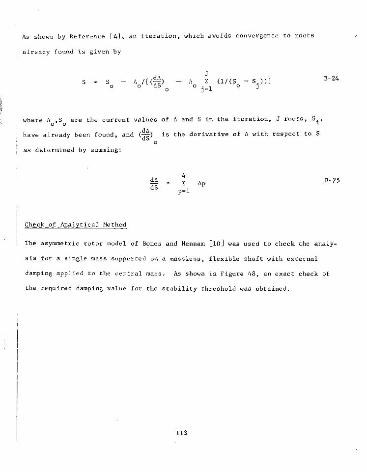
1
‘I w h e r e !i ,S are t h e c u r r e n t v a l u e s of A and S i n t h e i t e r a t i o n , J roots, S
~ have a.Lready been found, and (x) is t h e d e r i v a t i v e of A w i t h r e s p e c t t o S
0 0 j’ dA
0
~ as de te rmined by summing:
B- 24
B- 25
i 1 Check of Analy t ica l Method 1 I 1 The asymmetric rotor model of Bones and Hannam [ lo] was used t o check t he ana ly -
s i s for a s i n g l e mass suppor t ed on a m a s s l e s s , f l e x i b l e s h a f t w i t h e x t e r n a l
damping app l i ed t o t he cen t r a l mass. As shown i n F i g u r e 48 , a n e x a c t c h e c k of
t h e r e q u i r e d d a m p i n g v a l u e f o r t h e s t a b i l i t y t h r e s h o l d was o b t a i n e d .
113

30
20
10
0 0.5 1.0 1.5 \
I n\ i'" Thresho ld , €i* = 1.63 4 A s P r e d i c t e d
by R e f . (10) \ 1 \I
r .-! 1 7 1. \ I
2 . 5 Damping a t Mass, B l b s e c / i b
d = = .1334; w1 =
= 877.9 r a d / s e c
= J K2*/M = 1004. r a d / s e c 2
= 943.
I J I I I I 1
F i g . 48 Check o f S t a b i l i t y A n a l y s i s for Asymmetric Shaft . Comparison with Bones and Hannam (Ref. 10)

APPENDIX C
MTI COMMANDTN MULTIPLANE, MULTISPEED . BALANCING SYSTEM
The MTI m u l t i p l a n e , m u l t i s p e e d b a l a n c i n g s y s t e m i n i t s cu r ren t fo rm, as i t was
u s e d f o r t h e b a l a n c i n g e x p e r i m e n t s d e s c r i b e d i n t h i s r e p o r t , i s a f u r t h e r d e v e l -
opmen t o f t he non-compute r i zed da t a acqu i s i t i on sys t em p rev ious ly desc r ibed i n
Ref s . 2 & 3 . I n t h i s s y s t e m e l e c t r o n i c a n a l o g s i g n a l p r o c e s s i n g e q u i p m e n t h a s
been combined with a s e l f - c o n t a i n e d d a t a p r o c e s s i n g c e n t e r t o p r o v i d e f o r a u t o -
matic d a t a a c q u i s i t i o n , s i g n a l c o n d i t i o n i n g , a n d c o r r e c t i o n w e i g h t c a l c u l a t i o n s .
The r o l e o f t h e e q u i p m e n t o p e r a t o r d u r i n g b a l a n c i n g o p e r a t i o n s h a s b e e n r e d u c e d
t o s p e e d c o n t r o l o f t h e r o t o r t o be balanced and t r i a l a n d c o r r e c t i o n w e i g h t
addi t ion and removal as c a l l e d f o r by the compute r p r in t -ou t . The minicom-
p u t e r i n t h e s y s t e m c a n be programmed v i a punched paper t ape , before each ba l -
a n c i n g o p e r a t i o n , f o r t h e number of t r i a l w e i g h t l o c a t i o n s t o be used on the
r o t o r t o be ba lanced , the number o f s e n s o r s t o be used ,and the ba lanc ing speed
a t which ba lanc ing da ta i s t o be a c q u i r e d . Once t h e number of b a l a n c i n g p a r a -
me te r s has been dec ided upon and t he ba l anc ing speed va r i a t ion t o l e rances s e t
a t wh ich ba l anc ing da t a may be acqu i r ed , t he compute r w i l l a u t o m a t i c a l l y r e q u e s t
the p roper amount of da t a t o s a t i s f y t h e b a l a n c i n g r e q u i r e m e n t s . The computer
au tomat! .ca l ly examines the da ta f rom mul t ip le da ta read ings for cons is tency and
r e j e c t s a l l d a t a t h a t i s found to be o u t s i d e a c c e p t a b l e d i s t r i b u t i o n limits.
Data o r i g i n a t i n g o u t s i d e t h e p r e - s e t r o t o r s p e e d window i s r e j e c t e d . The com-
pu te r i n fo rms t he mach ine ope ra to r of e a c h s u c c e s s i v e s t e p t o be t a k e n i n
r o t o r s p e e d c o n t r o l a n d p r o v i d e s t h e o p e r a t o r w i t h a number of o p t i o n s i n p r o -
c e d u r e ; f o r e x a m p l e , he can choose to impose an a d d i t i o n a l trim b a l a n c e c o r r e c -
t i o n w e i g h t se t a f t e r c o m p l e t i o n of t h e r e g u l a r b a l a n c i n g o p e r a t i o n , a n d h e c a n
c o n t r o l the e x t e n t o f t h e p r i n t e d r e c o r d o n t h e b a l a n c i n g o p e r a t i o n f o r q u a l i t y
c o n t r o l o r o t h e r r e c o r d k e e p i n g p u r p o s e s .
The d a t a a c q u i s i t i o n s u b s y s t e m h a s t o a c c o m p l i s h t h e f o l l o w i n g f u n c t i o n s t y p i -
c a l of any advanced balancing machine:
1. F i l t e r i n g o f t h e e l e c t r o n i c a m p l i t u d e s i g n a l s w h i c h are p r o p o r t i o n a t e
t o r o t o r u n b a l a n c e .
115

2. M e a s u r e m e n t o f t h e f i l t e r e d a m p l i t u d e s i g n a l .
3 . P h a s e a n g l e d e t e r m i n a t i o n b e t w e e n e a c h f i l t e r e d a m p l i t u d e s i g n a l u s e d
f o r b a l a n c i n g a n d a f i x e d p o i n t o n t h e r o t o r .
4 . Automat i c s equen t i a l swi t ch ing among a m p l i t u d e s i g n a l s u s e d f o r
b a l a n c i n g .
The requi rements o f an au tomat ic s y s t e m add two more f u n c t i o n s t o t h e a c q u i -
s i t i o n s u b s y s t e m :
1. Con t ro l l i ng o f t he s equence and du ra t ion o f measu remen t , and i n t e r -
fac ing be tween ana lys i s components and be tween the ana log and d ig i ta l
systems.
2 . AID conver s ion o f t he ana log s igna l fo r compute r p rocess ing .
- The da ta process ing subsys tem has th ree components :
1. C e n t r a l p r o c e s s o r
2 . Magnetic memory
3 . Keyboard terminal
The se l ec t ion o f sys t em componen t s , wh ich gene ra l ly by t hemse lves are the mos t
advanced sys t ems o f t he i r k ind , was based upon p rev ious f l ex ib l e ro t , o r ba l -
a n c i n g e x p e r i e n c e . The c a p a b i l i t i e s i n c o r p o r a t e d i n t o t h e s y s t e m w i l l gener-
a l l y meet t h e m o s t a d v a n c e d r e q u i r e m e n t s i n f l e x i b l e r o t o r b a l a n c i n g . A
summary o f s y s t e m c a p a b i l i t i e s i s given below:
0 Inpu t channe l s : 20 a n a l o g s i g n a l s
0 I n p u t s i g n a l v o l t a g e : 1.0 MV t o 10 VRMS
0 I n p u t s i g n a l f r e q u e n c y : 2 Hz t o 2 kHz
0 Balanc ing p lanes : 20 +<
0 Balancing speeds: 5 ;k
*The las t two parameters can be expanded with addi t ional computer memory, i f
r e q u i r e d .
116

The m u l t i p l a n e , m u l t i s p e e d b a l a n c i n g s y s t e m p r o c e s s e s e l e c t r o n i c v i b r a t i o n
s i g n a l s i n t h e s p e c i f i e d v o l t a g e a n d f r e q u e n c y r a n g e , w i t h o u t r e g a r d t o t y p e
o f s o u r c e . I n d u c t i v e , c a p a c i t i v e , o r o p t i c a l d i s p l a c e m e n t s e n s o r s , v e l o c i t y
s e n s o r s , a c c e l e r o m e t e r s , s t r a i n g a g e s , o r o t h e r s e n s o r s p r o v i d i n g s i g n a l s p r o -
p o r t i o n a l t o r o t o r s y n c h r o n o u s l a t e r a l v i b r a t i o n may be used . Sensor l eads
w i t h BNC-type c o n n e c t i o n s may b e d i r e c t l y c o n n e c t e d .
A photo o f the comple te MTI m u l t i p l a n e , m u l t i s p e e d b a l a n c i n g s y s t e m i s shown
i n F i g u r e 49.
117

F i g . 49 MTI COMMANDTY Model 2005 Balancing System
118

1. Report No. 2. Government Accession No. -
NASA CR-2975 4. Title and Subtitle
BALANCING TECHNIQUES FOR HIGH-SPEED FLEXIBLE ROTORS
7. Author(s1
A. J. Smalley, J. M. Tessarzik, and R. A. Rio
9. Performing Organization Name and Address
Mechanical Technology Incorporated 9 68 Albany- Shaker Road Latham, New York 12110
2 . Sponsoring Agency Name and Address
National Aeronautics and Space Administration Washington, D. C. 20546
5. Supplementary Notes
3. Recipient's Catalog No. -
5. Report Date A p r i l 1978
6. Performing Organization Code
8. Performing Organization Report No. ~ - _ _ _
MTI 77TR2 10. Work Unit No
1 1 . Contract or Grant No
NAS3-18520 13. Type of Report and Period Covered
Contractor Report 14. Sponsoring Agency Code
.__
Final report. Project Manager, David P. Fleming, Fluid System Components Division, NASA Lewis Research Center, Cleveland, Ohio 44135.
6. Abstract
In this report, the topics of ideal and non-ideal conditions for multiplane balancing are ad- dressed. Methodology and procedures for identifying optimum balancing configurations and for assessing, quantitatively, the penalties associated with non-optimum configurations are devel- oped and demonstrated. The problems introduced when vibration sensors are supported on flexible mounts are assessed experimentally, and the effects of f lexural asymmetry in the rotor on balancing a r e investigated. A general-purpose method for predicting the threshold of insta- bility of an asymmetr ic rotor is developed, and its predictions are compared with measurements under different degrees of asymmetry.
- 7. Key Words (Suggested by Author(s))
""
Multiplane balancing of rotor with flexural asymmetry
Predicting instability threshold of asymmetr ic rotor
"_ 18. Distribution Statement
Unclassified - unlimited STAR Category 37
9. Security Classif. (of this report) 20. Security Classif. (o f this page1 ""
Unclassified Unclassified A07 . " -
For sale by the Natlonal Technical Information Service. Sprlngfleld. Vlrglnla 22161 NASA-Langley, 1978