1 © 2003, cisco systems, inc. all rights reserved. ccna 3 v3.0 module 9 virtual trunking protocol
TRANSCRIPT

1© 2003, Cisco Systems, Inc. All rights reserved.
CCNA 3 v3.0 Module 9Virtual Trunking Protocol

222© 2003, Cisco Systems, Inc. All rights reserved.
Objectives
• Trunking
• VTP
• Inter-VLAN routing

333© 2003, Cisco Systems, Inc. All rights reserved.
History of Trunking

444© 2003, Cisco Systems, Inc. All rights reserved.
Trunking Concepts
A trunk is a physical and logical connection between two switches across which network traffic travels.
Trunking bundles multiple virtual links over one physical link. This allows the traffic of several VLANs to travel over a single cable between the switches.

555© 2003, Cisco Systems, Inc. All rights reserved.
Frame Filtering

666© 2003, Cisco Systems, Inc. All rights reserved.
• VLAN Tagging is used when a link needs to carry traffic for more than one VLAN.
This link as packets are received by the switch from any attached end-station device, a unique packet identifier is added within each header.
• This header information designates the VLAN membership of each packet.
• The packet is then forwarded to the appropriate switches or routers based on the VLAN identifier and MAC address.
• Upon reaching the destination node (Switch) the VLAN ID is removed from the packet by the adjacent switch and forwarded to the attached device.
• Packet tagging provides a mechanism for controlling the flow of broadcasts and applications while not interfering with the network and applications.
• This is known as a trunk link or VLAN trunking.
• The two most common tagging schemes for Ethernet segments are ISL and 802.1Q
Frame Tagging

777© 2003, Cisco Systems, Inc. All rights reserved.
VLAN Tagging
• VLAN Tagging is used when a link needs to carry traffic for more than one VLAN.
• Tagging is used so the receiving switch knows which ports in should flood broadcast and unknown unicast traffic (only those ports belonging to the same VLAN).
No VLAN Tagging
VLAN Tagging

888© 2003, Cisco Systems, Inc. All rights reserved.
Inter-Switch Link Protocol
• Trunking protocols were developed to effectively manage the transfer of frames from different VLANs on a single physical line.
• The trunking protocols establish agreement for the distribution of frames to the associated ports at both ends of the trunk.
• Trunk links may carry traffic for all VLANs or only specific VLANs.

999© 2003, Cisco Systems, Inc. All rights reserved.
VLANs and Trunking
• It is important to understand that a trunk link does not belong to a specific VLAN.
• The responsibility of a trunk link is to act as a conduit for VLANs between switches and routers (or switches and switches).

101010© 2003, Cisco Systems, Inc. All rights reserved.
Frame Tagging and Encapsulation Methods
• There are two major methods of frame tagging, Cisco proprietary Inter-Switch Link (ISL) and IEEE 802.1Q.
• ISL used to be the most common, but is now being replaced by 802.1Q frame tagging.
• Cisco recommends using 802.1Q.

111111© 2003, Cisco Systems, Inc. All rights reserved.
Configuring Trunking
Note: On many switches, the switchport trunk encapsulation command must be done BEFORE the switchport mode trunk command.

121212© 2003, Cisco Systems, Inc. All rights reserved.
Switch(config-if)switchport mode [access|trunk]
• An access port means that the port (interface) can only belong to a single VLAN.
• Access ports are used when:
Only a single device is connected to the port
Multiple devices (hub) are connected to the port, all belonging to the same VLAN
Another switch is connected to this interface, but this link is only carrying a single VLAN (non-trunk link).
• Trunk ports are used when:
Another switch is connected to this interface, and this link is carrying multiple VLANs (trunk link).

131313© 2003, Cisco Systems, Inc. All rights reserved.
VLAN Trunking Protocol (VTP) Benefits

141414© 2003, Cisco Systems, Inc. All rights reserved.
VTP Concepts
The role of VTP is to maintain VLAN configuration consistency across a common network administration domain.
151515© 2003, Cisco Systems, Inc. All rights reserved.
VTP Operation – Revision Number
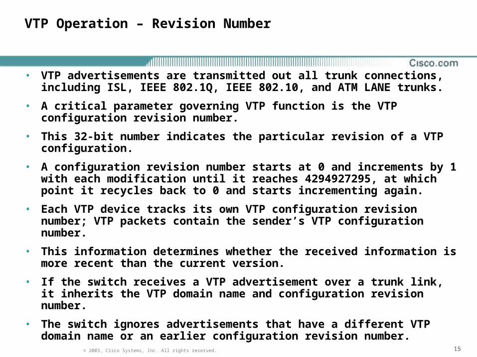
• VTP advertisements are transmitted out all trunk connections, including ISL, IEEE 802.1Q, IEEE 802.10, and ATM LANE trunks.
• A critical parameter governing VTP function is the VTP configuration revision number.
• This 32-bit number indicates the particular revision of a VTP configuration.
• A configuration revision number starts at 0 and increments by 1 with each modification until it reaches 4294927295, at which point it recycles back to 0 and starts incrementing again.
• Each VTP device tracks its own VTP configuration revision number; VTP packets contain the sender’s VTP configuration number.
• This information determines whether the received information is more recent than the current version.
• If the switch receives a VTP advertisement over a trunk link, it inherits the VTP domain name and configuration revision number.
• The switch ignores advertisements that have a different VTP domain name or an earlier configuration revision number.

161616© 2003, Cisco Systems, Inc. All rights reserved.
VTP Mode Comparison
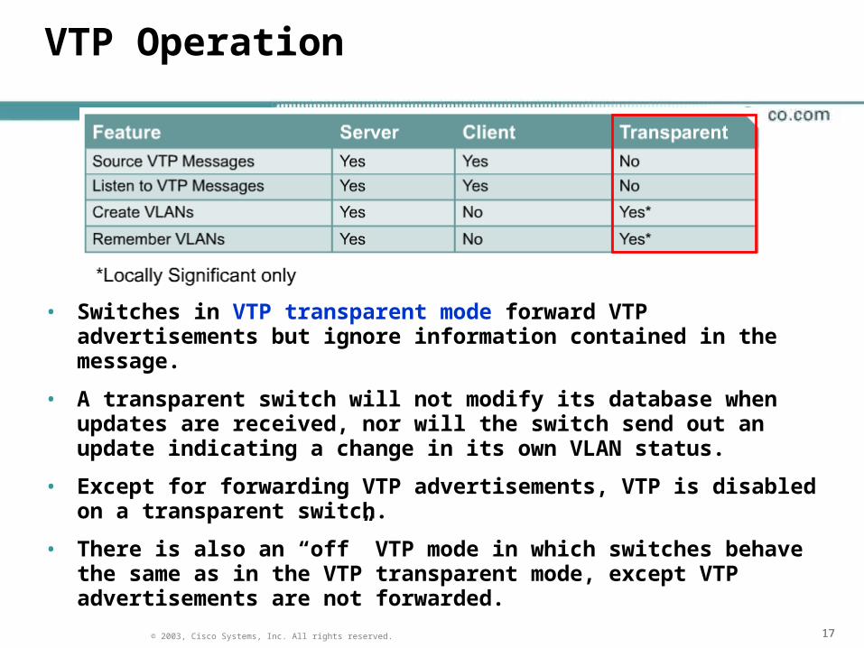
• VTP servers can create, modify, delete VLAN and VLAN configuration parameters for the entire domain.
• VTP servers save VLAN configuration information in the switch NVRAM. VTP servers send VTP messages out to all trunk ports.
• VTP clients cannot create, modify, or delete VLAN information.
• The only role of VTP clients is to process VLAN changes and send VTP messages out all trunk ports.
• The VTP client maintains a full list of all VLANs within the VTP domain, but it does not store the information in NVRAM.
• VTP clients behave the same way as VTP servers, but it is not possible to create, change, or delete VLANs on a VTP client.
• Any changes made must be received from a VTP server advertisement.
171717© 2003, Cisco Systems, Inc. All rights reserved.
VTP Operation
• Switches in VTP transparent mode forward VTP advertisements but ignore information contained in the message.
• A transparent switch will not modify its database when updates are received, nor will the switch send out an update indicating a change in its own VLAN status.
• Except for forwarding VTP advertisements, VTP is disabled on a transparent switch.
• There is also an “off” VTP mode in which switches behave the same as in the VTP transparent mode, except VTP advertisements are not forwarded.

181818© 2003, Cisco Systems, Inc. All rights reserved.
VTP Operation
191919© 2003, Cisco Systems, Inc. All rights reserved.
VTP Implementation
• There are two types of VTP advertisements:
Requests from clients that want information at bootup
Responses from servers
• There are three types of VTP messages:
Advertisement requests
Summary advertisements
Subset advertisements

202020© 2003, Cisco Systems, Inc. All rights reserved.
VTP Basic Configuration Steps
1. Determine the version number
2. Choose the domain
3. Choose the VTP mode
4. Password protect the domain

212121© 2003, Cisco Systems, Inc. All rights reserved.
VTP configuration - Version
• Two different versions of VTP can run in the management domain, VTP Version 1 and VTP Version 2.
• The two versions are not interoperable in the same VTP domain. The major difference between the two versions is version 2 introduces support for Token Ring VLANs.
• If all switches in a VTP domain can run VTP Version 2, version 2 only needs to be enabled on one VTP server switch.
• The version number is propagated to the other VTP Version 2-capable switches in the VTP domain. Version 2 should not be enabled unless every switch in the VTP domain supports version 2.

222222© 2003, Cisco Systems, Inc. All rights reserved.
VTP configuration – Domain and Password
• The domain name can be between 1 and 32 characters.
• The optional password must be between 8 and 64 characters long.
• If the switch being installed is the first switch in the network, the management domain will need to be created.
• However, if the network has other switches running VTP, then the new switch will join an existing management domain.
• Caution: The domain name and password are case sensitive.

232323© 2003, Cisco Systems, Inc. All rights reserved.
VTP configuration – Domain and Password
• By default, management domains are set to a nonsecure mode, meaning that the switches interact without using a password.
• Adding a password automatically sets the management domain to secure mode.
• The same password must be configured on every switch in the management domain to use secure mode.

242424© 2003, Cisco Systems, Inc. All rights reserved.
VTP configuration – VTP mode
Switch#config terminal
Switch(config)#vtp mode [client|server|transparent]
Switch#vlan database
Switch(vlan)#vtp [client|server|transparent]
252525© 2003, Cisco Systems, Inc. All rights reserved.
Inter-VLAN Routing
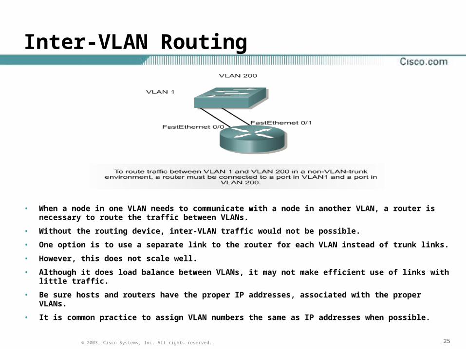
• When a node in one VLAN needs to communicate with a node in another VLAN, a router is necessary to route the traffic between VLANs.
• Without the routing device, inter-VLAN traffic would not be possible.
• One option is to use a separate link to the router for each VLAN instead of trunk links.
• However, this does not scale well.
• Although it does load balance between VLANs, it may not make efficient use of links with little traffic.
• Be sure hosts and routers have the proper IP addresses, associated with the proper VLANs.
• It is common practice to assign VLAN numbers the same as IP addresses when possible.

262626© 2003, Cisco Systems, Inc. All rights reserved.
Inter-VLAN Issues and Solutions
Two of the most common issues that arise in a multiple-VLAN environment are as follows:
– The need for end-user devices to reach nonlocal hosts
– The need for hosts on different VLANs to communicate

272727© 2003, Cisco Systems, Inc. All rights reserved.
Router on a Stick

282828© 2003, Cisco Systems, Inc. All rights reserved.
Physical and Logical Interfaces

292929© 2003, Cisco Systems, Inc. All rights reserved.
Dividing Physical Interfaces into Subinterfaces
A subinterface is a logical interface within a physical interface, such as the Fast Ethernet interface on a router. Multiple subinterfaces can exist on a single physical interface.

303030© 2003, Cisco Systems, Inc. All rights reserved.
Configuring Inter-VLAN Routing