1 2,3downloads.hindawi.com/journals/ijap/2017/3845851.pdf · 2017-12-21 · synthesis of a rotman...
TRANSCRIPT
Research ArticleMultiobjective Optimization of a Rotman Lens through theQLWS Minimization
Daniele Pinchera,1 Stefano Perna,2,3 and Marco Donald Migliore1
1DIEI-University of Cassino and Southern Lazio and ELEDIA@UNICAS, Via G. Di Biasio 43, 03043 Cassino, Italy2DI-University of Napoli “Parthenope”, Centro Direzionale, Isola C4, 80143 Napoli, Italy3IREA-CNR, Via Diocleziano 328, 80124 Napoli, Italy
Correspondence should be addressed to Daniele Pinchera; [email protected]
Received 10 August 2017; Revised 27 October 2017; Accepted 14 November 2017; Published 21 December 2017
Academic Editor: Shiwen Yang
Copyright © 2017 Daniele Pinchera et al. This is an open access article distributed under the Creative Commons AttributionLicense, which permits unrestricted use, distribution, and reproduction in any medium, provided the original work isproperly cited.
We address the multiobjective optimization of a Rotman lens by means of a recently proposed method based on the minimizationof a properly defined global cost function named Quantized Lexicographic Weighted Sum (QLWS). More specifically, we haveconsidered three different objectives concurring during the optimal synthesis of the lens. First, the difference between actual anddesired delay among the excitations of the array elements fed by the lens needs to be lower than a given threshold. Second, gainlosses of the beams scanned by the array fed by the lens need to be lower than a given threshold. Third, lens insertion lossesshould be as low as possible. Exploitation of the QLWS based approach allowed us to obtain in a few minutes a Rotman lensfulfilling these three concurring objectives and to improve the starting result obtained by a commercial software.
1. Introduction
The Rotman lens [1] is a planar structure implementing atrue delay line beam-forming network (BFN) for lineararrays that are required to radiate different scanned beamswithin a given angular portion.
Due to practical relevance of Rotman lens, synthesismethods are a wide investigation subject. In particular, ifone accepts that the delay among the excitations of the arrayelements fed by the lens is not perfectly linear for all thebeams to be scanned, the lens synthesis gets easier. Indeed,in this case, it basically requires the optimal choice of justthree specific geometric parameters of the focal arc wherethe input ports of the lens will be located [1]. In this regard,it is noted that the design of a Rotman lens involves theachievement of different concurring targets and/or con-straints, such as the reduction of the lens insertion losses,the gain losses of the scanned beams, and the lens encum-brance. Accordingly, the optimal calculation of the threeunknowns needed for the design of a Rotman lens generallyrequires solving a multiobjective problem [2–4]. However,
although many papers have been written [5–13] with theaim of improving the lens architecture originally proposedby Rotman, just a few of them focus on the multiobjectivenature of the lens synthesis.
In this work, we address such aspect. More specifically,we carry out a multiobjective optimization of a Rotman lens,by exploiting the method recently proposed in [14] for thesynthesis of sparse arrays. In particular, the method is basedon the minimization of a properly defined global cost func-tion (GCF) inspired by the lexicographic order rules andnamed quantized lexicographic weighted sum (QLWS). Incontrast to other optimization tools in electromagnetics[15–18], such QLWS-based approach allows to define apriori, in a simple and effective way, the priorities amongthe different optimization objectives, thus making it unneces-sary to build cumbersome Pareto optimal fronts [19, 20].
In particular, we have considered three different optimi-zation objectives. First, the difference between actual anddesired delay among the excitations of the array elementsfed by the lens needs to be lower than a given threshold. Sec-ond, gain losses of the beams scanned by the array fed by the
HindawiInternational Journal of Antennas and PropagationVolume 2017, Article ID 3845851, 6 pageshttps://doi.org/10.1155/2017/3845851

lens need to be lower than a given threshold. Third, lensinsertion losses should be as low as possible. We started fromthe solution provided by a single-objective optimization toolimplemented by a commercial software, and through theQLWS-based approach, in a few minutes, we improved itby obtaining a Rotman lens fulfilling all the three consideredobjectives.
2. Synthesis of a Rotman Lens
Let us briefly recall the basic principle of the Rotmanlens design.
As a well-known design, this architecture allows the real-ization of a true delay line beam-forming network (BFN) forlinear arrays by means of an extension of the Ruze lens [21]to a three focus architecture.
The basic scheme of the lens is depicted in Figure 1 for alinear array that is required to radiate M different beams inthe range θ ∈ −α, α , being θ the angular deviation from thebroadside direction. The considered array consists of L equis-paced antennas, say Aℓ, ℓ ∈ 1,… , L . In the figure, theantennas are deployed along the y-axis: their positions are(x0, yℓ), ℓ ∈ 1,… , L , with constant interelement distance d.
The lens consists of a set of M input ports, denotedwith Pm, m ∈ 1,… ,M , and a set of L output ports.The input ports are associated to the different M scannedbeams to be radiated, whereas the output ports are associ-ated to the L array antennas. The input ports are con-nected by transmission lines to corresponding M ports,with coordinates (xbm, ybm), m ∈ 1,… ,M , lying on theinput curve depicted in cyan in the figure. The outputports, with coordinates (xpℓ, ypℓ), ℓ ∈ 1,… , L , lie on theoutput curve, depicted in red in the figure, and are connectedby transmission lines of electrical length δℓ, ℓ ∈ 1,… , L , tothe corresponding array antennas.
In principle, the design of the lens would involve thecalculation of 2M + 3L unknowns represented by the portcoordinates (xbm, ybm), m ∈ 1,… ,M , on the input curve,the port coordinates (xpℓ, ypℓ), ℓ ∈ 1,… , L , on the output
curve, and the electrical lengths δℓ, ℓ ∈ 1,… , L . However,the number of the unknowns can be significantly reducedfollowing the rationale in [1], where the input curve is builtas a circular arc, called the focal arc, passing through threefoci, say F1, F2, and F3, with coordinates
F1 = −Fcos γ , Fsin γ ,F2 = −Fcos γ , −Fsin γ ,F3 = −G, 0 ,
1
where the distances F and G and the angle γ are highlightedin Figure 1. The three foci F1, F2, and F3 in (1) identify threespecific input ports: F1 and F2 are associated to the maxi-mally scanned beams, that is, the beams to be radiated inthe directions θ = α and θ = −α, respectively, whereas F3 isassociated to the broadside beam (θ = 0). Once the positionsof F1, F2, and F3 in (1) are set, the positions of the remainingM − 3 input ports can be easily achieved by equispacing themon the focal arc between F1 and F2. The remaining 3Lunknowns represented by the length δℓ and the coordi-nates (xpℓ, ypℓ) can be instead obtained by solving, forℓ ∈ 1,… , L , the following set of three equations:
dist F1, Ppℓ + δℓ + yℓcos α = F + δ0,dist F2, Ppℓ + δℓ − yℓcos α = F + δ0,dist F3, Ppℓ + δℓ = G + δ0,
2
where δ0 is an inessential offset term [1]. Note that theseequations (2) enforce the condition that the foci F1 and F2are associated to the maximally scanned beams and the focusF3 to the broadside one.
Summing up, once the electrical array parameters(number M of input ports, number L of antennas, andmaximum scanning angle α) are defined, the overall lensdesign basically requires the proper choice for the threeparameters F, G, and γ in (1) and (2).
The drawback of this approach is that, at least in princi-ple, only the input ports located in the three foci show a per-fect linear delay among the excitations of all antenna
P1
P2
P3F3
PM
...
F2
F1
(xbm,ybm) (xpl,ypl)
G
F
y
A1
A2
Al
x�휃
�훿l
�훿2
�훿1
... ...
Figure 1: Geometry of the Rotman lens.
2 International Journal of Antennas and Propagation

elements. A deviation with respect to this ideal condition isinstead expected for the other ports, which are associated tothe beams other than the broadside and the maximallyscanned ones. Accordingly, a quite obvious criterion for thechoice of the three unknowns F, G, and γ is to achieve a delayamong the excitations of the antenna elements as linear aspossible for all the input ports, in such a way to well radiateall the different M scanned beams.
On the other side, it could be worth accounting for otherconcurring constraints and/or targets during the synthesis ofa Rotman lens. First of all, to limit the gain losses when scan-ning the beam far away from the broadside direction, thefield amplitude difference between the different scannedbeams should be as low as possible. Furthermore, the lensinsertion losses should be limited as much as possible.Finally, to meet the encumbrance and weight constraints thatare typically enforced during the design of the overallantenna, the lens dimensions should be kept as small aspossible. Of course, some other constraints could be required,as a specific range for the dimension of the ports, in order toensure practical realizability. Accordingly, to obtain the opti-mal choice of the three parameters F, G, and γ in (1) and (2),we have to deal with multiple concurring targets and differentconstraints. In other words, we have to solve a multiobjective(“multicriteria” or “multiparameter” or “multitarget”) prob-lem. To do this, in the following, we set a priori the prioritiesamong the different concurring targets listed above andexploit the method recently proposed in [14] for the multiob-jective synthesis of sparse arrays. The method, which is basedon the minimization of a properly defined GCF namedQLWS and inspired by the lexicographic order rules, is brieflyrecalled in the next section; for further details, the reader canrefer to [14].
3. Main Rationale of the QLWSMinimization Method
Let us consider a generic multiobjective problem, wherethe N optimization objectives, say xk, k ∈ 1,… ,N , arecharacterized by different N levels of priorities, say pk, k∈ 1,… ,N , definedapriori. The approach in [14] addressessuch kind of problem through the minimization of a GCFbuilt as follows:
QLWS = 〠N
k=1Bpkceil B − 1 Dk xk , 3
where B is a base number and ceil takes the minimum inte-ger greater or equal than its argument. Moreover, Dk xk is afunction that maps each optimization objective xk onto a realnumber ranging within the interval I = 0, 1 : the smaller thevalue ofDk xk , the closer the fulfilment of the target relevantto xk. Some examples of Dk xk can be found in [14] and arenot reported here for brevity.
The weighted sum in (3) is inspired by the lexicographicordering rules, from which it retains its name, that is,quantized lexicographic weighted sum, briefly QLWS. Mini-mization of the QLWS in (3) has been introduced in [14] forthe synthesis of sparse arrays; in particular, multiobjective
global optimization was performed in that case. In thefollowing section, we show that the QLWS can be exploitedalso to perform a multiobjective local optimization, asrequired for the synthesis of a Rotman lens.
4. Numerical Results
As an example, let us consider the multiobjective optimiza-tion of a Rotman lens for the beamforming of an array oper-ating at a central frequency f = 9 6GHz and consisting ofL = 16 vertical λ/2 wire dipoles, horizontally equispaced withinterelement distance d = λ/2. In particular, let us considerM = 16 and α = π/6.
For such a kind of array, it can be shown that the scanningproperties, even for the maximally scanned beam, are verymarginally affected by the mutual coupling effects. Accord-ingly, such effects are not considered during the synthesis ofthe lens.
The lens is implemented in microstrip, with permittivityϵr = 2 2 and substrate height hsub = 0 5mm.
In our case, we consider the following three optimizationobjectives:
(i) Objective 1: the difference between actual and desireddelay among the excitations of the array elementsfed by the lens needs to be lower than a giventhreshold;
(ii) Objective 2: the gain losses of the beams scannedby the array fed by the lens need to be lower thana given threshold;
(iii) Objective 3: lens insertion losses should be as low aspossible;
Moreover, as clarified in Section 3, to exploit the QLWSin (3), we have to set a priori the priorities among the differ-ent optimization objectives listed above. According to theconsiderations carried out in Section 2, we give the highestpriority to objective 1. This constraint can be coded by con-sidering on one side the actual optical paths connecting theinput ports and the antennas and on the other side the idealpaths that would ensure perfect linear delay among the exci-tations of the antenna elements. The maximum differencebetween these paths (maximum path error, briefly MPE)has to be as low as possible, say less that one-thousandth ofwavelength. The subsequent level of priority is given to objec-tive 2. In particular, we enforce that the amplitude variationbetween the beams (scan loss, briefly SL) must be less than0.2 dB. Finally, the lowest priority is given to objective 3. Inparticular, we enforce that the insertion loss, briefly IL,should be as low as possible. These priorities are translatedinto the QLWS in (3) by exploiting the following settings:
(i) N = 3 and B = 104;(ii) p1 = 2, D1 MPE built as in (4) with MPEmin = 10−3
λ and MPEmax = 10−1 λ;(iii) p2 = 1, D2 SL built as in (4) with SLmin = 0 2 dB and
SLmax = 10 dB;
3International Journal of Antennas and Propagation
(iv) p3 = 0, D3 IL built as in (4) with ILmin = 0 dB andILmax = 10 dB.
D x =
1, if x > xmax,0, if x > xmin,
x − xminxmax − xmin
, otherwise,4
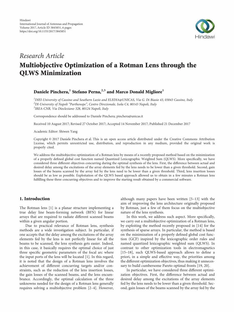
As discussed in [14], the “ceiling” function in (3) isdropped for the lowest priority target. It is also remarkedthat the QLWS in (3) can be exploited by any availablesingle-target optimization algorithm capable of handlingdiscontinuities in the cost function. In particular, weexploited the Nelder-Mead optimization (implemented inthe Matlab “fminsearch” function), which is a local searchalgorithm. Availability of a good starting point was thusneeded to achieve better performances. In particular, as astarting solution, we have considered a layout automaticallyobtained by means of the Rotman lens designer (RLD) soft-ware by Remcom. Such a layout is shown in Figure 2, and itsmain parameters are reported in Table 1. The benchmarkingof the lenses has been obtained by means of a custom-builtray tracing code, developed following the guidelines in[22]. From Table 1, we understand that the starting lens
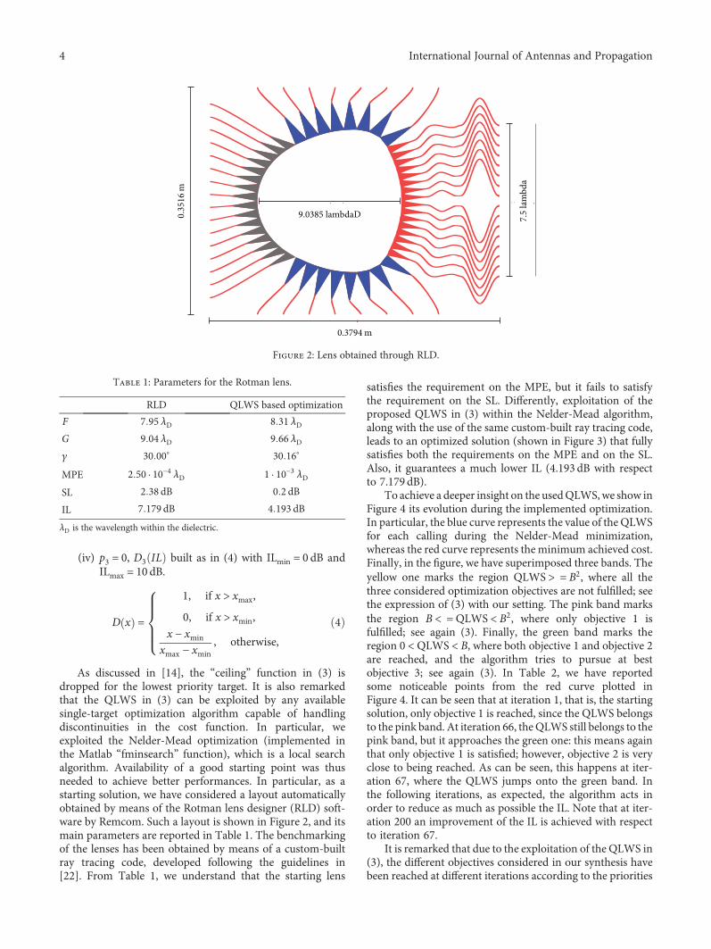
satisfies the requirement on the MPE, but it fails to satisfythe requirement on the SL. Differently, exploitation of theproposed QLWS in (3) within the Nelder-Mead algorithm,along with the use of the same custom-built ray tracing code,leads to an optimized solution (shown in Figure 3) that fullysatisfies both the requirements on the MPE and on the SL.Also, it guarantees a much lower IL (4.193 dB with respectto 7.179 dB).
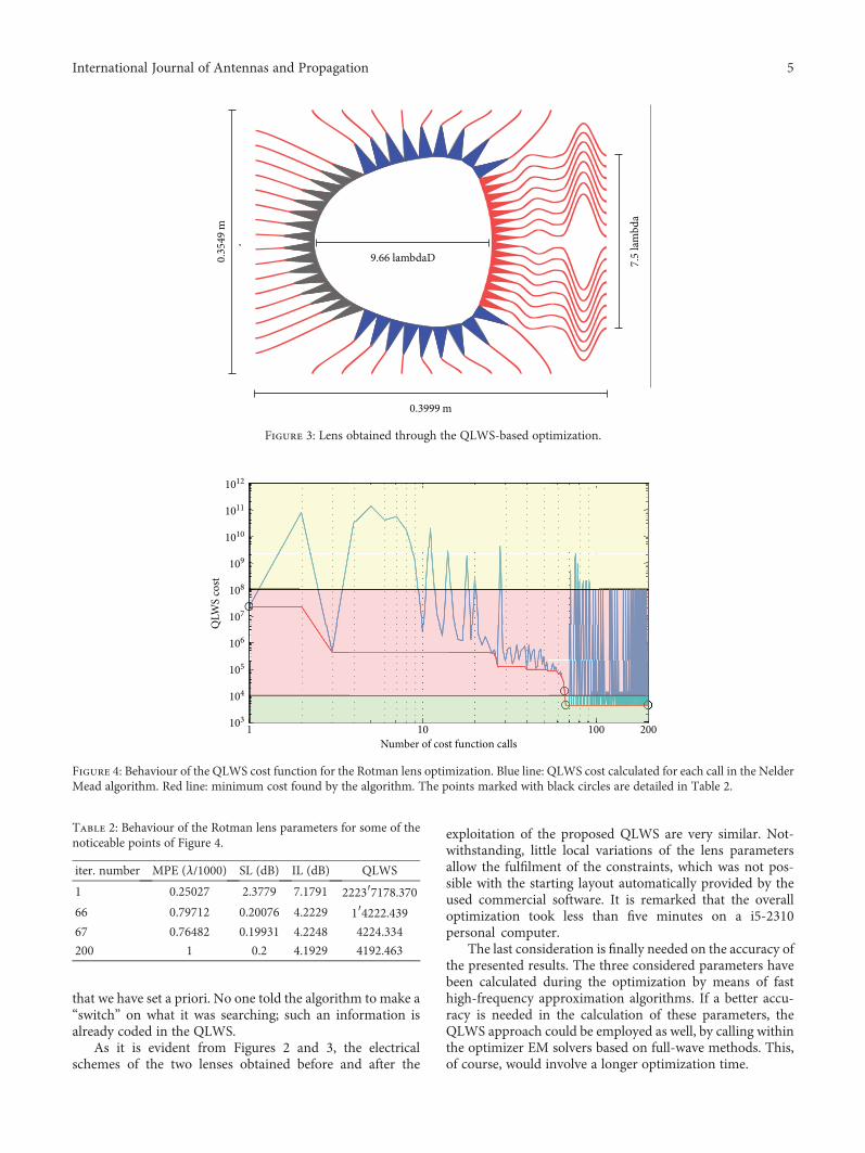
To achieve a deeper insight on the usedQLWS,we show inFigure 4 its evolution during the implemented optimization.In particular, the blue curve represents the value of the QLWSfor each calling during the Nelder-Mead minimization,whereas the red curve represents the minimum achieved cost.Finally, in the figure, we have superimposed three bands. Theyellow one marks the region QLWS > = B2, where all thethree considered optimization objectives are not fulfilled; seethe expression of (3) with our setting. The pink band marksthe region B < = QLWS < B2, where only objective 1 isfulfilled; see again (3). Finally, the green band marks theregion 0 < QLWS < B, where both objective 1 and objective 2are reached, and the algorithm tries to pursue at bestobjective 3; see again (3). In Table 2, we have reportedsome noticeable points from the red curve plotted inFigure 4. It can be seen that at iteration 1, that is, the startingsolution, only objective 1 is reached, since the QLWS belongsto the pink band. At iteration 66, theQLWS still belongs to thepink band, but it approaches the green one: this means againthat only objective 1 is satisfied; however, objective 2 is veryclose to being reached. As can be seen, this happens at iter-ation 67, where the QLWS jumps onto the green band. Inthe following iterations, as expected, the algorithm acts inorder to reduce as much as possible the IL. Note that at iter-ation 200 an improvement of the IL is achieved with respectto iteration 67.
It is remarked that due to the exploitation of the QLWS in(3), the different objectives considered in our synthesis havebeen reached at different iterations according to the priorities
0.35
16 m
0.3794 m
7.5
lam
bda
9.0385 lambdaD
Figure 2: Lens obtained through RLD.
Table 1: Parameters for the Rotman lens.
RLD QLWS based optimization
F 7 95 λD 8 31 λDG 9 04 λD 9 66 λDγ 30 00∘ 30 16∘
MPE 2 50 · 10−4 λD 1 · 10−3 λDSL 2 38 dB 0 2 dBIL 7 179 dB 4 193 dBλD is the wavelength within the dielectric.
4 International Journal of Antennas and Propagation
that we have set a priori. No one told the algorithm to make a“switch” on what it was searching; such an information isalready coded in the QLWS.
As it is evident from Figures 2 and 3, the electricalschemes of the two lenses obtained before and after the
exploitation of the proposed QLWS are very similar. Not-withstanding, little local variations of the lens parametersallow the fulfilment of the constraints, which was not pos-sible with the starting layout automatically provided by theused commercial software. It is remarked that the overalloptimization took less than five minutes on a i5-2310personal computer.
The last consideration is finally needed on the accuracy ofthe presented results. The three considered parameters havebeen calculated during the optimization by means of fasthigh-frequency approximation algorithms. If a better accu-racy is needed in the calculation of these parameters, theQLWS approach could be employed as well, by calling withinthe optimizer EM solvers based on full-wave methods. This,of course, would involve a longer optimization time.
0.35
49 m
0.3999 m
7.5
lam
bda
9.66 lambdaD
Figure 3: Lens obtained through the QLWS-based optimization.
1 10 100 200Number of cost function calls
103
104
105
106
107
108
109
1010
1011
1012
QLW
S co
st
Figure 4: Behaviour of the QLWS cost function for the Rotman lens optimization. Blue line: QLWS cost calculated for each call in the NelderMead algorithm. Red line: minimum cost found by the algorithm. The points marked with black circles are detailed in Table 2.
Table 2: Behaviour of the Rotman lens parameters for some of thenoticeable points of Figure 4.
iter. number MPE (λ/1000) SL (dB) IL (dB) QLWS
1 0.25027 2.3779 7.1791 2223′7178.37066 0.79712 0.20076 4.2229 1′4222.43967 0.76482 0.19931 4.2248 4224.334
200 1 0.2 4.1929 4192.463
5International Journal of Antennas and Propagation

5. Conclusions
In this work, we have discussed the multiobjective optimi-zation of a Rotman lens, by means of a relatively novelcost function, the quantized lexicographic weighted sum(QLWS). This function allows the solution of multicriteriaproblems, handling the optimization constraints accordingto their priorities.
Such QLWS has recently been proposed to address themultiobjective global optimization related to the synthesis ofsparse arrays. We have now demonstrated that by its usageit is possible to perform alsomultiobjective local optimization.
In particular, the use of the QLWS, together with theNelder-Mead optimizer, allowed to significantly improve thedesign solution of a Rotman lens provided by a commercialsoftware. Also, the obtained final layout correctly satisfied allthe design specifications.
It is worth noting that the presented approach is one of thefew that allows a local multicriteria optimization, and the pre-sented results confirm the effectiveness of the lexicographicapproach that allows the translation of the specifications ofthe problem in a simple and direct way.
Conflicts of Interest
The authors declare that there is no conflict of interestsregarding the publication of this paper.
Acknowledgments
This work was partially developed within a research contract,signed in 2015, between the University of Napoli “Parthe-nope” and the University of Cassino and Southern Lazio.
References
[1] W. Rotman and R. Turner, “Wide-angle microwave lens forline source applications,” IEEE Transactions on Antennasand Propagation, vol. 11, no. 6, pp. 623–632, 1963.
[2] R. T. Marler and J. S. Arora, “Survey of multi-objectiveoptimization methods for engineering,” Structural and Multi-disciplinary Optimization, vol. 26, no. 6, pp. 369–395, 2004.
[3] R. C. Hansen, “Design trades for Rotman lenses,” IEEETransactions on Antennas and Propagation, vol. 39, no. 4,pp. 464–472, 1991.
[4] S. Vashist, M. K. Soni, and P. K. Singhal, “A review on thedevelopment of Rotman lens antenna,” Chinese Journal ofEngineering, vol. 2014, Article ID 385385, 9 pages, 2014.
[5] T. Katagi, S. Mano, and S. Sato, “An improved design methodof Rotman lens antennas,” IEEE Transactions on Antennasand Propagation, vol. 32, no. 5, pp. 524–527, 1984.
[6] D. R. Gagnon, “Procedure for correct refocusing of theRotman lens according to Snell’s law,” IEEE Transactions onAntennas and Propagation, vol. 37, no. 3, pp. 390–392, 1989.
[7] P. K. Singhal, P. C. Sharma, and R. D. Gupta, “Rotman lenswith equal height of array and feed contours,” IEEE Transac-tions on Antennas and Propagation, vol. 51, no. 8, pp. 2048–2056, 2003.
[8] R. Uyguroglu and A. Y. Oztoprak, “A method for minimizingthe phase errors of Rotman lenses,” in 2009 International
Conference on Electrical and Electronics Engineering - ELECO2009, pp. II-174–II-176, Bursa, Turkey, 2009.
[9] R. P. S. Kushwah and P. K. Singhal, “Design of 2d-bootlacelens with five focal feed for multiple beam forming,” Journalof Electromagnetic Analysis and Applications, vol. 3, no. 2,pp. 39–42, 2011.
[10] W. Zongxin, X. Bo, and Y. Fei, “A multibeam antenna arraybased on printed Rotman lens,” International Journal ofAntennas and Propagation, vol. 2013, Article ID 179327,6 pages, 2013.
[11] A. Attaran and S. Chowdhury, “Fabrication of a 77GHzRotman lens on a high resistivity silicon wafer using lift-offprocess,” International Journal of Antennas and Propagation,vol. 2014, Article ID 471935, 9 pages, 2014.
[12] Y. Liu, H. Yang, S. Mao, and J. Zhu, “A multibeam dual-bandorthogonal linearly polarized antenna array for satellite com-munication on the move,” International Journal of Antennasand Propagation, vol. 2015, Article ID 102959, 8 pages, 2015.
[13] M. Rajabalian and B. Zakeri, “Optimisation and implementa-tion for a non-focal Rotman lens design,” IET Microwaves,Antennas & Propagation, vol. 9, no. 9, pp. 982–987, 2015.
[14] D. Pinchera, S. Perna, and M. D. Migliore, “A lexicographicapproach for multi-objective optimization in antenna arraydesign,” Progress In Electromagnetics Research M, vol. 59,pp. 85–102, 2017.
[15] Y. Rahmat-Samii and E. Michielssen, “Electromagneticoptimization by genetic algorithms,” Microwave Journal,vol. 42, no. 11, p. 232, 1999.
[16] A. Hoorfar, “Evolutionary programming in electromagneticoptimization: a review,” IEEE Transactions on Antennas andPropagation, vol. 55, no. 3, pp. 523–537, 2007.
[17] M. Donelli, D. Franceschini, P. Rocca, and A. Massa, “Three-dimensional microwave imaging problems solved through anefficient multiscaling particle swarm optimization,” IEEETransactions on Geoscience and Remote Sensing, vol. 47,no. 5, pp. 1467–1481, 2009.
[18] P. Rocca, G. Oliveri, and A. Massa, “Differential evolution asapplied to electromagnetics,” IEEE Antennas and PropagationMagazine, vol. 53, no. 1, pp. 38–49, 2011.
[19] T. Goel, R. Vaidyanathan, R. T. Haftka,W. Shyy, N. V. Queipo,and K. Tucker, “Response surface approximation of Paretooptimal front in multi-objective optimization,” ComputerMethods in Applied Mechanics and Engineering, vol. 196,no. 4-6, pp. 879–893, 2007.
[20] K. Deb, “Multi-objective optimization,” in Search Methodolo-gies, pp. 403–449, Springer, Boston, MA, USA, 2014.
[21] J. Ruze, “Wide-angle metal-plate optics,” Proceedings of theIRE, vol. 38, no. 1, pp. 53–59, 1950.
[22] J. Dong and A. I. Zaghloul, “Hybrid ray tracing method formicrowave lens simulation,” IEEE Transactions on Antennasand Propagation, vol. 59, no. 10, pp. 3786–3796, 2011.
6 International Journal of Antennas and Propagation

RoboticsJournal of
Hindawi Publishing Corporationhttp://www.hindawi.com Volume 2014
Hindawi Publishing Corporationhttp://www.hindawi.com Volume 2014
Active and Passive Electronic Components
Control Scienceand Engineering
Journal of
Hindawi Publishing Corporationhttp://www.hindawi.com Volume 2014
International Journal of
RotatingMachinery
Hindawi Publishing Corporationhttp://www.hindawi.com Volume 2014
Hindawi Publishing Corporation http://www.hindawi.com
Journal of
Volume 201
Submit your manuscripts athttps://www.hindawi.com
VLSI Design
Hindawi Publishing Corporationhttp://www.hindawi.com Volume 201
Hindawi Publishing Corporationhttp://www.hindawi.com Volume 2014
Shock and Vibration
Hindawi Publishing Corporationhttp://www.hindawi.com Volume 2014
Civil EngineeringAdvances in
Acoustics and VibrationAdvances in
Hindawi Publishing Corporationhttp://www.hindawi.com Volume 2014
Hindawi Publishing Corporationhttp://www.hindawi.com Volume 2014
Electrical and Computer Engineering
Journal of
Advances inOptoElectronics
Hindawi Publishing Corporation http://www.hindawi.com
Volume 2014
The Scientific World JournalHindawi Publishing Corporation http://www.hindawi.com Volume 2014
SensorsJournal of
Hindawi Publishing Corporationhttp://www.hindawi.com Volume 2014
Modelling & Simulation in EngineeringHindawi Publishing Corporation http://www.hindawi.com Volume 2014
Hindawi Publishing Corporationhttp://www.hindawi.com Volume 2014
Chemical EngineeringInternational Journal of Antennas and
Propagation
International Journal of
Hindawi Publishing Corporationhttp://www.hindawi.com Volume 2014
Hindawi Publishing Corporationhttp://www.hindawi.com Volume 2014
Navigation and Observation
International Journal of
Hindawi Publishing Corporationhttp://www.hindawi.com Volume 2014
DistributedSensor Networks
International Journal of