05381 - corrosion monitoring - corr instruments · real-time monitoring of corrosion in soil...
TRANSCRIPT

REAL-TIME MONITORING OF CORROSION IN SOIL UTILIZING COUPLED MULTIELECTRODE ARRAY SENSORS
Xiaodong Sun Corr Instruments, LLC San Antonio TX, USA
ABSTRACT
Real-time corrosion monitoring for carbon steel materials in soil was conducted utilizing coupled
multielectrode sensors. It was demonstrated that the coupled multielectrode sensor is an effective real-time tool for monitoring the corrosion rate in soil. The steady state corrosion rate measured in water-saturated soil was found to be approximately 2 to15 µm/year. However, the corrosion rate in a space filled with water was several orders of magnitude higher than those found in the densely packed soil saturated with water. The coupled multielectrode sensor also provided real-time indications for the effectiveness of cathodic protection in soil.
Keywords: Corrosion monitoring, corrosion in soil, corrosion sensor, localized corrosion, online corrosion sensor, corrosion probe, real-time corrosion sensor, multielectrode sensor, coupled multiple electrodes, cathodic protection.
INTRODUCTION
Corrosion of metallic components in soil has been a concern in many fields, including the
pipeline industry and nuclear waste disposal programs. Metal loss corrosion probes based on electrical resistance methods have been used as online tools for corrosion monitoring in soil1-4. However, these probes are not sensitive enough for localized corrosions, such as pitting or crevice corrosion5. Coupled multielectrode sensors have been recently used as in situ or online monitors for localized corrosions in laboratories and industry applications6-13. Some of the examples include quantitative and real-time corrosion monitoring for cathodically protected systems11and coated metal components12. The coupled multielectrode probes were also used as a real-time corrosion monitor for the corrosion of carbon steel rebar material in concrete13. In the present work, coupled multielectrode corrosion probes were used to online measure the corrosion rate of carbon steel material in soil. The experimental results of corrosion rates under different conditions, including cathodic protection conditions, are presented in this paper.
EXPERIMENTAL PROCEDURES
A nanoCorrTM*A-50 coupled multielectrode analyzer,11-14 manufactured by Corr Instruments (San Antonio, TX, USA), was used in the experiment (Figure 1). Figure 2 shows the principle of the analyzer. The analyzer couples the multiple sensing electrodes made of the same material as that used in a given application to a common joint through resistors. In a non-uniform corrosion condition, some of the electrodes corrode in preference to others and therefore a dispersion in the measured currents from sensing electrodes is observed. Thus, the multiple electrodes in the probe simulate a single piece of metal6-8. If the sensing elements are sufficiently small so that separation of anodic and cathodic reactions between different electrodes can be assumed, the localized corrosion rates can be obtained directly from the measured current densities, which correspond to non-uniform corrosion. The coupled multielectrode corrosion analyzer shown in Figure 1 has a high current resolution (10–12 A) and allows the measurement of coupling currents for up to 50 electrodes. It can be used with three separate 16-electrode probes at the same time.
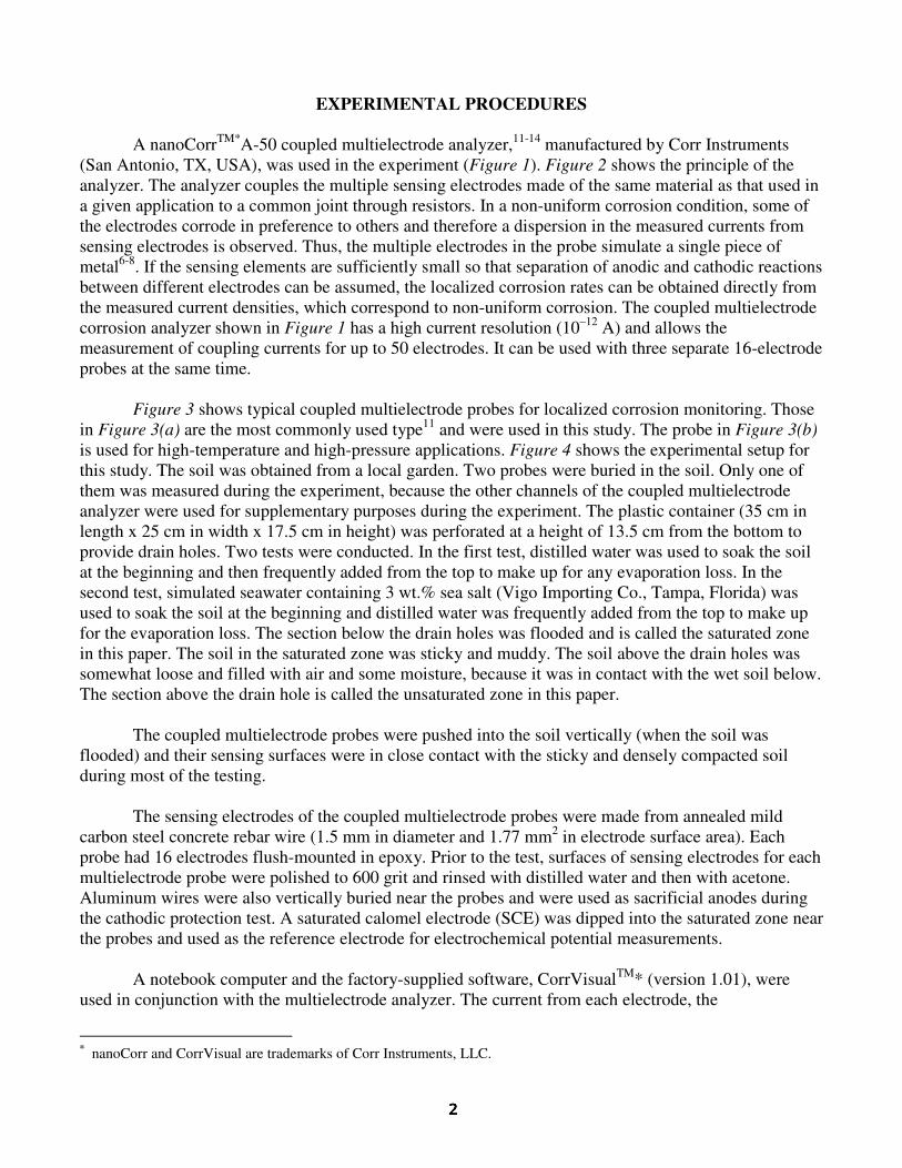
Figure 3 shows typical coupled multielectrode probes for localized corrosion monitoring. Those in Figure 3(a) are the most commonly used type11 and were used in this study. The probe in Figure 3(b) is used for high-temperature and high-pressure applications. Figure 4 shows the experimental setup for this study. The soil was obtained from a local garden. Two probes were buried in the soil. Only one of them was measured during the experiment, because the other channels of the coupled multielectrode analyzer were used for supplementary purposes during the experiment. The plastic container (35 cm in length x 25 cm in width x 17.5 cm in height) was perforated at a height of 13.5 cm from the bottom to provide drain holes. Two tests were conducted. In the first test, distilled water was used to soak the soil at the beginning and then frequently added from the top to make up for any evaporation loss. In the second test, simulated seawater containing 3 wt.% sea salt (Vigo Importing Co., Tampa, Florida) was used to soak the soil at the beginning and distilled water was frequently added from the top to make up for the evaporation loss. The section below the drain holes was flooded and is called the saturated zone in this paper. The soil in the saturated zone was sticky and muddy. The soil above the drain holes was somewhat loose and filled with air and some moisture, because it was in contact with the wet soil below. The section above the drain hole is called the unsaturated zone in this paper.
The coupled multielectrode probes were pushed into the soil vertically (when the soil was flooded) and their sensing surfaces were in close contact with the sticky and densely compacted soil during most of the testing.
The sensing electrodes of the coupled multielectrode probes were made from annealed mild carbon steel concrete rebar wire (1.5 mm in diameter and 1.77 mm2 in electrode surface area). Each probe had 16 electrodes flush-mounted in epoxy. Prior to the test, surfaces of sensing electrodes for each multielectrode probe were polished to 600 grit and rinsed with distilled water and then with acetone. Aluminum wires were also vertically buried near the probes and were used as sacrificial anodes during the cathodic protection test. A saturated calomel electrode (SCE) was dipped into the saturated zone near the probes and used as the reference electrode for electrochemical potential measurements.
A notebook computer and the factory-supplied software, CorrVisualTM* (version 1.01), were used in conjunction with the multielectrode analyzer. The current from each electrode, the
* nanoCorr and CorrVisual are trademarks of Corr Instruments, LLC.

electrochemical potential (the coupling potential) of each probe, and the temperature were logged at a predetermined interval (usually 20 to 600 seconds) and saved in a computer file. Processed signals, such as the localized corrosion current, the cumulative charge for each sensor, and the corrosion rate and cumulative corrosion damage (or penetration depth) for each probe, were also saved in one or more separate data files. During the measurements, all the directly measured currents and the processed results (such as the minimum current, maximum current, mean current, current densities, corrosion rates, cumulative charges, penetration depth, and electrochemical potential) were dynamically displayed from the computer screen in both numerical and graphical forms. The configuration parameters for data acquisition were also available on the computer screen.
The coupled multielectrode probes and the corrosion analyzer used in this study were tested in a distilled water, a simulated seawater (same salt as used in the present study), and a solution of simulated seawater plus 10 mM H2O2 at room temperature. The results were reported in a previous publication 11
(Figure 5). The electrodes of the coupled multielectrode probes used for Figure 5 were made from the same carbon steel wire (1.5 mm in diameter) as that used in the present study.
Figure 6 shows a schematic diagram for the wiring configuration between the multielectrode probes, the reference electrode, and the sacrificial anodes with the corrosion analyzer. The coupling joint of the analyzer is shown in Figures 1 and 2.
RESULTS AND DISCUSSIONS Corrosion Rate in Soil Saturated with Distilled Water
Figure 7 shows the measured corrosion rate from one of the coupled multielectrode array probes buried in the soil soaked in distilled water. The non-uniform corrosion rate (localized corrosion rate) was approximately 4 nm/year (0.0002 mil/year) in air, which is below the lower detection limit of the analyzer (10 nm/year). Upon the insertion into the distilled water-soaked soil, the signal instantly increased by more than 6 orders of magnitude to 0.8 mm/year, which is close to the rate of the carbon steel material in simulated seawater (see Figure 5). The corrosion rate decreased steeply in a few minutes and reached 10 µm/year within two hours. Following the steep decrease, the corrosion rate was from 5 to 15 µm/year during the eleven days of test. The post test examination indicated that the sensing electrode was not very corroded and the polishing marks were still clearly visible. Khan2 reported a corrosion rate of 71 µm/year for a steel material with no cathodic protection, from a field measurement in soil using electrical resistance probe. Since the soil chemistry in Khan’s field test and the soil chemistry in this study were not characterized, it is difficult to compare the two results. In addition, the corrosion rate reported by Khan was the uniform corrosion rate and the rate measured with the multielectrode array probe is for non-uniform corrosion. The rapid decrease of corrosion rate shortly after the insertion of the probe into the soil was probably due to the formation of corrosion products and the depletion of reactants (oxygen for example). The low steady-state corrosion rate was probably due to the low diffusion rate of the reactants and products involved in the corrosion process.
Figure 8 shows the non-uniform corrosion penetration depths, which were calculated by the
software using the published procedure6 and based on the signal measured from the coupled multielectrode array probe during the time period corresponding to Figure 7. The calculated penetration depth was also displayed by the software during the measurement. Most of the penetration caused by non-uniform corrosion took place in the first day after the insertion of the probe into the distilled water-soaked soil.

Corrosion Rates in Water-Filled Space and in Unsaturated Soil
During the test in the distilled water-soaked soil (Figures 7 and 8), the probe was in the saturated zone and the sensing surface of the probe was in close contact with the muddy and dense soil. At the end of this test, the probe was raised such that the sensing surface was near the level of the drain holes (Figure 4). By raising the probe, a space was created underneath the probe sensing surface and the space was filled with the surrounding water. Figure 9 shows the non-uniform corrosion rates measured from the probe when it was in the space filled with water near the unsaturated zone of the soil. The corrosion rate instantly increased from 5 µm to 130 µm/year and continued to increase further after the probe was raised. By the time the probe was taken out of the soil, the corrosion rate reached 350 µm/year. This value is between the rate measured in pure distilled water and the rate measured in 3 wt.% sea salt water (see Figure 5), which is reasonable, because the soil used in the test contains various minerals and contaminants even though distilled water was used to soak the soil. In addition, the oxygen content of the water in the space is probably close to the solubility value (8 ppm), because the space is close to the unsaturated soil that contained many voids filled with air.
To start another test in simulated seawater-soaked soil (see below), the probes were repolished,
cleaned and buried in another container filled with loose soil. The soil was freshly excavated from the garden and contained moisture, but was not wet. Figure 9 also shows the non-uniform corrosion rate measured in the freshly prepared unsoaked soil. The corrosion rate of the carbon steel probe was from 0.1 to 0.2 µm/year. Because the newly prepared soil was loose and contained moisture but was not wet, many voids were filled with air. The value measured in the fresh soil represents the corrosion rate for carbon steel under solid deposits in moist air. Yang et. al.15 have measured the corrosion rate of carbon steel (Type 1010, UNS G10100) under potassium chloride (KCl) deposit at different humidity levels. The corrosion rates they obtained varied significantly and were between 0.05 µm/year and 5 mm/year, depending on the relative humidity. As KCl deposit is more corrosive than the fresh loose soil used in this study, the corrosion rate obtained by Yang et al. is expected to be higher than the corrosion rate obtained in this study under the same relative humidity.
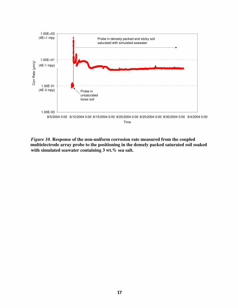
Corrosion Rate in Soil Saturated with Simulated Seawater
A solution containing 3 wt.% sea salt was added to the freshly prepared soil. The soil in the
saturated zone became sticky and more densely packed and the probes were pushed into the soil so that their sensing surfaces were in close contact with the soil. Figure 10 shows the response of the non-uniform corrosion rate measured from the coupled multielectrode array probe to the addition of the simulated seawater. As expected, the corrosion rate instantly increased to approximately 600 µm/year, which is close to the rate for the carbon steel material in simulated seawater (see Figure 5). However, a few minutes after the change, the rate dropped rapidly. It was initially anticipated that the corrosion rate in the simulated seawater-soaked soil would be higher than that measured in distilled water-filled soil. However, the comparison (Figure 11) indicates that the corrosion rate in the simulated seawater-soaked soil was not higher than that in the distilled water-soaked soil. In fact, on average, the corrosion rate measured in the seawater-soaked soil was slightly lower than that in the distilled water-soaked soil. It is not known what caused the unexpected behavior. It may be due to the fact that the soil was highly heterogeneous in chemical and physical properties. The soil in contact with the probe’s sensing surface in the simulated seawater-soaked soil test may not have been as corrosive as the soil near the probe’s sensing surface in the distilled water-soaked soil. The unexpected behavior may also be an indication that the corrosion rates in soil saturated with both the distilled water and the simulated seawater were under mass-transfer control, and that dissolved salts (mainly sodium chloride) are expected to increase

the conductivity of the soil and also modify the properties near the corroding metal surface so that they are more favorable for localized corrosion. However, if the corrosion process was under mass-transfer control, the migrations of the corrosion products (such as metal ions) away from the corroding sites and the reactants (such as O2) to the corroding sites are limited by the low diffusion rates of these species in the soil, and the increase in chloride content would not change the steady-state corrosion rate.
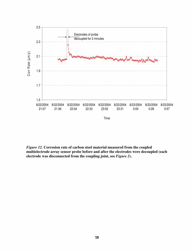
During the tests, the probe was disconnected from the corrosion analyzer several times. When
the probes were disconnected from the multielectrode corrosion analyzer, the electrodes in the probes were decoupled (each electrode was left at open-circuit condition). It was found that the corrosion rate was usually higher immediately after the probe was reconnected to the corrosion analyzer to resume the measurement. This behavior is illustrated in Figure 12. The increase observed when the probe was re-coupled is attributed to the mass-transfer effect. At the time the electrodes were decoupled, there was no continued flow of electrons, due to corrosion from the anodic electrodes to the cathodic electrodes. The corrosion products produced during the coupling had more time to diffuse away from the corroded sites, and the reactants had more time to diffuse to the corroded sites. At the time the probe was reconnected and the electrodes in the probe were coupled, the electron flows due to non-uniform corrosion resumed. Because of the relatively high concentrations of reactants and low concentrations of corrosion products near the electrodes, the recorded corrosion rate was initially high but decreased rapidly, reaching the value prior to the decoupling. In the measurement of corrosion in concrete, such behavior was more obvious13. During that measurement, the corrosion potential immediately after the re-coupling was found to be slightly lower than the value prior to the decoupling, and then gradually increased to the previous value. The lower corrosion potential suggests that the higher corrosion current immediately after the re-coupling was probably due to the lower concentration of the corrosion products, rather than the higher concentration of the oxidant at the electrode surfaces.
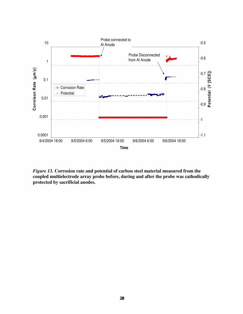
Corrosion Rate under Cathodic Protection Conditions
At the end of the test with the simulated seawater-soaked soil, the carbon steel electrodes of the probe were connected to the aluminum sacrificial anodes (Figure 6), to cathodically protect the electrodes. Figure 13 shows the measured corrosion rate and the electrochemical potential of the carbon steel electrodes before, during, and after the cathodic protection. As soon as the carbon steel electrodes were cathodically protected, the electrochemical potential decreased from -0.72 V(SCE) to -0.83 V(SCE), and the corrosion rate dropped from 3 µm/year to 1.3 nm/year, which is below the lower detection limit of the corrosion analyzer (10 nm/year). This suggests that the carbon steel material was adequately protected. When the cathodic protection was removed, the potential returned to -0.72 V(SCE) and the corrosion current returned to approximately 2.2 µm/year.
CONCLUSION
A real-time coupled multielectrode array sensor probe was used to measure the corrosion rate of
carbon steel material in soil. The steady-state corrosion rate measured in the densely packed soil saturated with distilled water or with simulated seawater was found to be approximately 2 to 15 µm/year. However the corrosion rate of the carbon steel material measured in a space filled with water near the water-air interface was several orders of magnitude higher than those found in the densely packed soil. When the carbon steel electrodes of the probe were connected to sacrificial aluminum anodes, the corrosion rate decreased instantaneously to a value that is below the lower detection limit of the instrument (10 nm/year), suggesting that the coupled multielectrode array sensor probe is an effective real-time tool to measure the effectiveness of cathodic protection.

ACKNOWLEDGMENTS
The author acknowledges Narasi Sridhar and Lietai Yang for their technical discussions, useful suggestions and valuable comments.
REFERENCES
1. N. A. Khan, “Use of ER Soil Corrosion Probes to Determine the Effectiveness of Cathodic
Protection”, CORROSION/2002, paper no. 02104 (Houston, TX: NACE, 2002). 2. N. A. Khan, “Using Electrical Resistance Soil Corrosion Probes to Determine Cathodic
Protection Effectiveness in High-Resistivity Soils”, Materials Performance, Vol. 43, No. 6 (June, 2004) p. 20.
3. I. Betova, J. Heinonen, P. Kinnunen, C. Lija, E. Ruokola and T. Sarrio, “Application of an On-
line Corrosion Probe and a Reference Electrode for Copper Corrosion Studies in Repository Conditions” in Scientific Basis for Nuclear Waste Management XXVII (MRS Meeting, Kalmar, Sweden, 2003), V. M. Oversby and L. Werme Eds., Warrendale, PA: Materials Research Society, M.R.S. Symposium Proceedings, Vol. 807 (2003), pp 429-434.
4. P. Kempe, A. Denzine and E. Tiefnig, “Rapid Underground Corrosion Measurements for Buried
Pipelines”, CORROSION/2000, paper no. 00092 (Houston, TX: NACE, 2000). 5. L. Yang and N. Sridhar, "Monitoring of Localized Corrosion ASM Handbook”, Volume 13A-
Corroson: Fundamentals, Testing, and Protection, Stephen. D. Crammer and Bernard S. Covino, Jr. Eds, ASM International, Materials Park, Ohio, 2003, pp 519-524.
6. L. Yang, N. Sridhar, O. Pensado, and D.S. Dunn, Corrosion, 58 (2002), p.1004. 7. L. Yang and N. Sridhar, “Coupled Multielectrode Online Corrosion Sensor”, Materials
Performance, 42(9), pp 48-52 (2003). 8. M. H. Dorsey, L. Yang and N. Sridhar, “Cooling Water Monitoring Using Coupled
Multielectrode Array Sensors and Other On-line Tools”, CORROSION/2004, paper no. 04077, (Houston, TX: NACE International, 2004).
9. L. Yang, R.T. Pabalan, L. Browning, and G.C. Cragnolino, “Measurement of Corrosion in
Saturated Solutions under Salt Deposits Using Coupled Multielectrode Array Sensors,” CORROSION/2003, paper no. 426 (Houston, TX: NACE, 2003).
10. C.S. Brossia and L. Yang, “Studies of Microbiologically Induced Corrosion Using a Coupled
Multielectrode Array Sensor,” CORROSION/2003, paper no. 575 (Houston, TX: NACE, 2003). 11. X. Sun, “Xiaodong Sun, "Online Monitoring of Corrosion under Cathodic Protection Conditions
Utilizing Coupled Multielectrode Sensors", CORROSION/2004, paper no. 04094, (Houston, TX: NACE International, 2004).
12. X. Sun, “Online Monitoring of Undercoating Corrosions Utilizing Coupled Multielectrode
Sensors,” CORROSION/2004, paper no.04033 (Houston, TX: NACE, 2004).

13. X. Sun, “Online and Real-Time Monitoring of Carbon Steel Corrosion in Concrete, Using
Coupled Multielectrode Sensors,” CORROSION/2005, paper no.05267 (Houston, TX: NACE, 2005).
14. Corr Instruments, “Coupled Multielectrode Online Corrosion Sensor Analyzer”, Materials
Performance, 43(2), p55 (2004). 15. L. Yang, R. T. Pabalan, L. Browning and D.S. Dunn, “Corrosion Behavior of Carbon Steel and
Stainless Steel Materials under Salt Deposits in Simulated Dry Repository Environments”, in Scientific Basis for Nuclear Waste Management XXVI R. J. Finch and D. B. Bullen eds, Warrendale, PA: Materials Research Society, M.R.S. Symposium Proceedings Vol. 757, pp.791-797, 2003.

Figure 1. Coupled multielectrode array sensor analyzer system used in the experiment. As shown in the picture, the analyzer was used to measure the corrosion rates and corrosion potentials simultaneously for three independent 16-electrode probes.
Coupling Joint
Reference Electrode Connector
Temperature Sensor
Probe Connector

Figure 2. Schematic diagram showing the principle of the coupled multielectrode array sensor analyzer used in the experiment.
Instrument couples the electrodes viaresistors and measures the electrons
from and to individual electrodes
e-
e- e-e-
e-e- e-
Anodic sites: M - ne- + nH2O = M(OH)n + nH+
(Electrons flow internally from anodic sites to cathodic sites)
Cathodic sites: O2 + 4e- + 2H2O = 4OH-
e-
e-
e-e-
e-
e-e- e-e-
e-
e-
e-e-
e- e-
e-
Anodic and cathodic sites are separated but coupled externally. Electrons are forced to flow externally
e-
Insu-lator Electrode
CouplingJoint
Metal
Electro-lyte
Figure 3. Typical coupled multielectrode array sensor probes.
(a) ��������Probes used in the present studies and for typical applications; (b) ���� Probe for high-temperature and high-pressure systems.
(a)
(b)

Figure 4. Experimental setup during the measurement of corrosion rates in soil.
Note: The Al anodes were used for cathodic protection during the test.
Unsaturated Zone
Drain Holes
Saturated Zone
Al Anodes
Ref. Electrode

Figure 5. Typical responses of a probe made of rebar carbon steel material to the changes of solution chemistry11.
0.01
0.10
1.00
10.00
100.00
1000.00
10000.00
100000.00
0.0 1.0 2.0 3.0 4.0 5.0 6.0
Time (day)
Cor
rosi
on R
ate
(mic
rom
eter
/yea
r)
0
0
0
0
1
10
100
1000
Cor
rosi
on R
ate
(m
il/ye
ar)
Distilled Water
3%wt Sea Salt
3%wt Sea Salt+10 mM H2O2
3%wt Sea Salt
Dry Air Dry Air
3937
394
39.4
3.94
0.394
0.0394
0.00394
0.000394
Distilled Water

Figure 6. Schematic diagram showing wiring configuration during the cathodic protection test.
Reference Electrode
Multi-electrode
probe
Corrosion Analyzer
Soil
Sacrificial Anodes
Reference Connector
Coupling Joint
Probe Connector
Reference Electrode
Multi-electrode
probe
Corrosion Analyzer
Soil
Sacrificial Anodes
Reference Connector
Coupling Joint
Probe Connector

1.0E-04
1.0E-02
1.0E+00
1.0E+02
7/23/20040:00
7/25/20040:00
7/27/20040:00
7/29/20040:00
7/31/20040:00
8/2/20040:00
8/4/20040:00
8/6/20040:00
8/8/20040:00
Time
Cor
r Rat
e ( µ
m/y
)
Probe in air
Probe in densely packed sticky soil saturated with distilled water (4E+0 mpy)
(4E-4 mpy)
Figure 7. Corrosion rates from the coupled multielectrode array probe made of low carbon steel material.
Note: The corrosion rate in air was slightly below the specified lower detection limit of the instrument (10 nm/year).

1.0E-05
1.0E-04
1.0E-03
1.0E-02
1.0E-01
1.0E+00
7/23/20040:00
7/25/20040:00
7/27/20040:00
7/29/20040:00
7/31/20040:00
8/2/20040:00
8/4/20040:00
8/6/20040:00
8/8/20040:00
Time
Pen
etra
tion
Dep
th (µ
m) (4E-3 mil)
(4E-2 mil)
Probein air
(4E-4 mil)
(4E-6 mil)
Probe in densely packed sticky soil saturated with distilled water
Figure 8. Corrosion penetration depths calculated by the instrument software from the signal of the coupled multielectrode array probe, made of low carbon steel material, for the time period corresponding to Figure 7.

1.0E-02
1.0E+00
1.0E+02
1.0E+04
8/4/2004 0:00 8/5/2004 0:00 8/6/2004 0:00 8/7/2004 0:00 8/8/2004 0:00
Time
Cor
r Rat
e ( µ
m/y
)
Probe in soil saturated with distilled water for 10 days
Probe raised to near the water-air interface; a water-filled space formed beneath the probe's sensing surface
Probe repolished, cleaned and burried in freshly prepared soil that was loose and unsaturated with water
(4E+0 mpy) mil)
(4E+2 mpy)
(4E-2 mpy)
Figure 9. Non-uniform corrosion rate measured from the probe at different locations of the soil container.
1.00E-03
1.00E-01
1.00E+01
1.00E+03
8/5/2004 0:00 8/10/2004 0:00 8/15/2004 0:00 8/20/2004 0:00 8/25/2004 0:00 8/30/2004 0:00 9/4/2004 0:00
Time
Cor
r Rat
e ( µ
m/y
)
Probe in densely packed and sticky soil saturated with simulated seawater
Probe in unsaturatedloose soil
(4E-1 mpy)
(4E+1 mpy
(4E-3 mpy)
Figure 10. Response of the non-uniform corrosion rate measured from the coupled multielectrode array probe to the positioning in the densely packed saturated soil soaked with simulated seawater containing 3 wt.% sea salt.

1.0E-04
1.0E-02
1.0E+00
1.0E+02
7/22/20040:00
7/27/20040:00
8/1/20040:00
8/6/20040:00
8/11/20040:00
8/16/20040:00
8/21/20040:00
8/26/20040:00
8/31/20040:00
9/5/20040:00
Time
Cor
r Rat
e ( µ
m/y
)
Air
Unsaturated loose soil
Soil soaked with simulated seawater
Soil soaked with distilled water
Water-filled space
Figure 11. Comparison of the corrosion rates from the coupled multielectrode array sensor probe in different soil environments.
1.5
1.7
1.9
2.1
2.3
2.5
8/22/200421:07
8/22/200421:36
8/22/200422:04
8/22/200422:33
8/22/200423:02
8/22/200423:31
8/23/20040:00
8/23/20040:28
8/23/20040:57
Time
Cor
r Rat
e ( µ
m/y
)
Electrodes of probe decoupled for 2 minutes
Figure 12. Corrosion rate of carbon steel material measured from the coupled multielectrode array sensor probe before and after the electrodes were decoupled (each electrode was disconnected from the coupling joint, see Figure 2).
0.0001
0.001
0.01
0.1
1
10
9/4/2004 18:00 9/5/2004 6:00 9/5/2004 18:00 9/6/2004 6:00 9/6/2004 18:00
Time
Cor
rois
on R
ate
( µµ µµm
/y)
-1.1
-1
-0.9
-0.8
-0.7
-0.6
-0.5
Pot
entia
l (V
[SC
E])
Corrosion RatePotential
Probe connected to Al Anode
Probe Disconnected from Al Anode
Figure 13. Corrosion rate and potential of carbon steel material measured from the coupled multielectrode array probe before, during and after the probe was cathodically protected by sacrificial anodes.