mygetinteractive.commygetinteractive.com/3ds_max_2015_lmt/sunlight_and... · web viewin this...
TRANSCRIPT

Let Me Try!
Sunlight and ShadowIn this tutorial, you will create an animated scene to study the shadow pattern according to the position of the sun over the earth at a particular location, date, and time. The shadow at one of the frames is shown in in the image below.
Creating the Project Folder
Create a new project folder with the name c15_tut1 at \Documents\3dsmax2015 and then save the file with the name c15tut1
Creating a Ground and a TreeIn this section, you will create the ground by using the Plane tool.
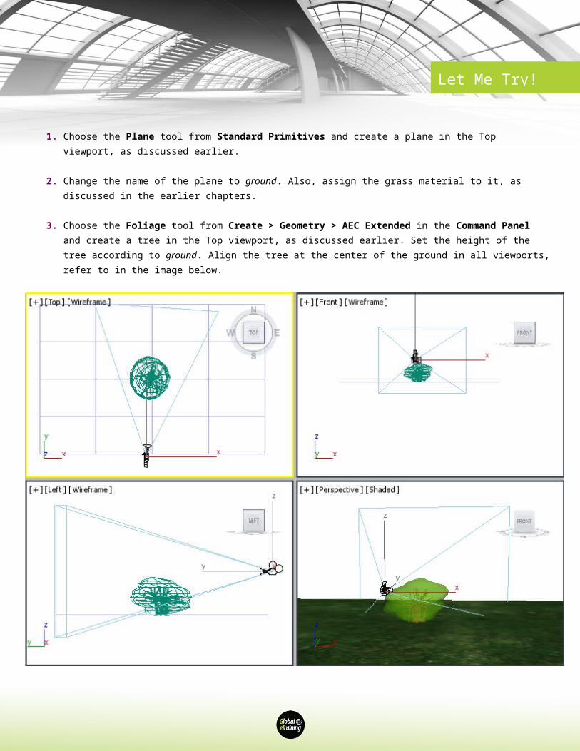
1. Choose the Plane tool from Standard Primitives and create a plane in the Top viewport, as discussed earlier.
Let Me Try!
2. Change the name of the plane to ground. Also, assign the grass material to it, as discussed in the earlier chapters.
3. Choose the Foliage tool from Create > Geometry > AEC Extended in the Command Panel and create a tree in the Top viewport, as discussed earlier. Set the height of the tree according to ground. Align the tree at the center of the ground in all viewports, refer to in the image below.
Creating and Modifying
In this section, you will apply an image to the LCD screen of the computer.

Let Me Try!
1. Display the image on your computer screen and press the PRT SCR keys. Next, open the Paint software and press the CTRL+V keys to paste the image. Now, save the file with the name desktop_screen in the jpg format at the following location:
\Documents\3dsmax2015\c07_tut3\sceneassets\images.
1. In the Rendering rollout, select the Enable in Renderer and Enable in Viewport check boxes. Make sure that the Radial radio button is selected. Next, set the value 3.5 in the Thickness spinner. The image below shows the rectangle displayed in the viewports.
2. In the Name and Color rollout, enter the name inner frame and press the ENTER key. and use the color swatch to change its color by using the following values:
Red: 248 Green: 58 Blue: 0
Aligning Boxes
In this section, you will align the left and right boxes together. 1. Choose the Select and Move tool and make sure right box is selected. Move right box along the X, Y,
and Z axes in all viewports to align it with left box, as shown in the image below. Click in the viewport and choose the Zoom Extents All tool from the viewport navigation controls to view the box in all viewports, refer to the image below.
Creating the DrawerIn this section, you will create drawers of the table and then clone the drawers.
1. Create another box in the Top viewport and enter the following values in the Parameters rollout:
Length: 90 Width: 55 Height: 25
Note :While aligning the objects, you need to make sure that the objects are aligned properly in all viewports.

Let Me Try!
2. In the Name and Color rollout, enter drawer001 and press ENTER; the object is renamed. Choose the color swatch to change the color of drawer001; the Object Color dialog box is displayed. Choose the Add Custom Colors button; the Color Selector: Add Color dialog box is displayed. In this dialog box, specify the values as given below:
Red: 177 Green: 88 Blue: 27
3. Choose the Add Color button from the Color Selector: Add Color dialog box to add the selected color. The color is displayed in one of the Custom Color boxes in the Object Color dialog box. Choose the OK button; the new color is assigned to drawer001.
4. Align drawer001 with left box in viewports using the Select and Move tool, as shown in the image below.

Let Me Try!
Creating Clones of the Drawer
In this section, you will create copies of drawer001.
1. Activate the Front viewport and make sure drawer001 Figure 2-51 The Clone Options dialog box is selected. Next, move the cursor over the Y axis, press and hold the SHIFT key, and drag drawer001 downward until the value in the Y spinner of the Coordinate display at the bottom of the screen becomes around -29. Release the left mouse button and the SHIFT key; the Clone Options dialog box is displayed, as shown in the image below.

Let Me Try!
2. Make sure the Copy radio button is selected in the Object area of the Clone Options dialog box. In the Number of Copies spinner, enter 2 to create two copies of drawer001. Next, choose the OK button; two drawers with same dimensions are created, as shown in the image below.

Let Me Try!
3. Create another box in the Top viewport and in the Parameters rollout, enter the values as follows:
Length: 90 Width: 70 Height: 17
4. Name the newly created box as drawer004 and change its color as you did for the drawers created previously.
5. Align drawer004 with the right box in viewports, as shown in the image below.
Note: The cloned objects are automatically named sequentially as drawer002 and drawer003, based on the name of the original object. You can also clone an object by holding the SHIFT key while rotating or scaling it.
Let Me Try!
Creating Outer Faces of the Table
In this section, you will create outer faces of the table to make it appear more realistic.
1. Create a box in the Left viewport and in the Parameters rollout, enter the values given below:
Length: 95.5 Width: 90 Height: 1.5
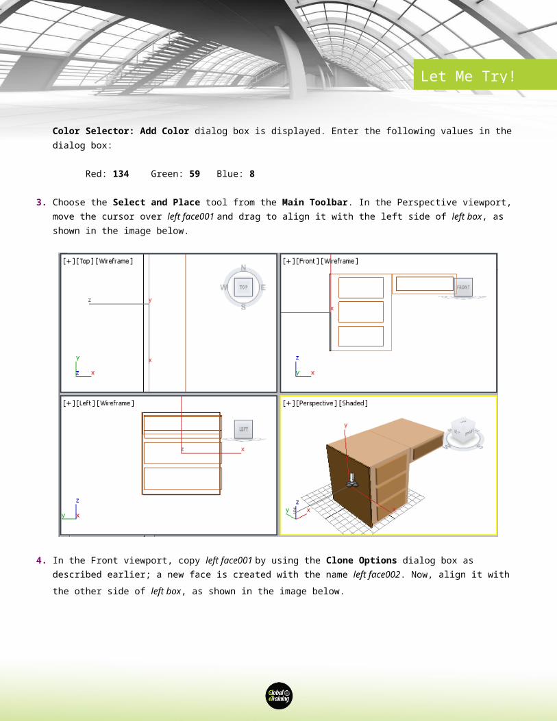
2. In the Name and Color rollout, enter left face001 and press ENTER; the box is named as left face001. Choose the color swatch to change the color of left face001; the Object Color dialog box is displayed. Choose the Add Custom Colors button from this dialog box; the Color Selector: Add Color dialog box is displayed. Enter the following values in the dialog box:
Red: 134 Green: 59 Blue: 8
3. Choose the Select and Place tool from the Main Toolbar. In the Perspective viewport, move the cursor over left face001 and drag to align it with the left side of left box, as shown in the image below.
Let Me Try!
4. In the Front viewport, copy left face001 by using the Clone Options dialog box as described earlier; a new face is created with the name left face002. Now, align it with the other side of left box, as shown in the image below.
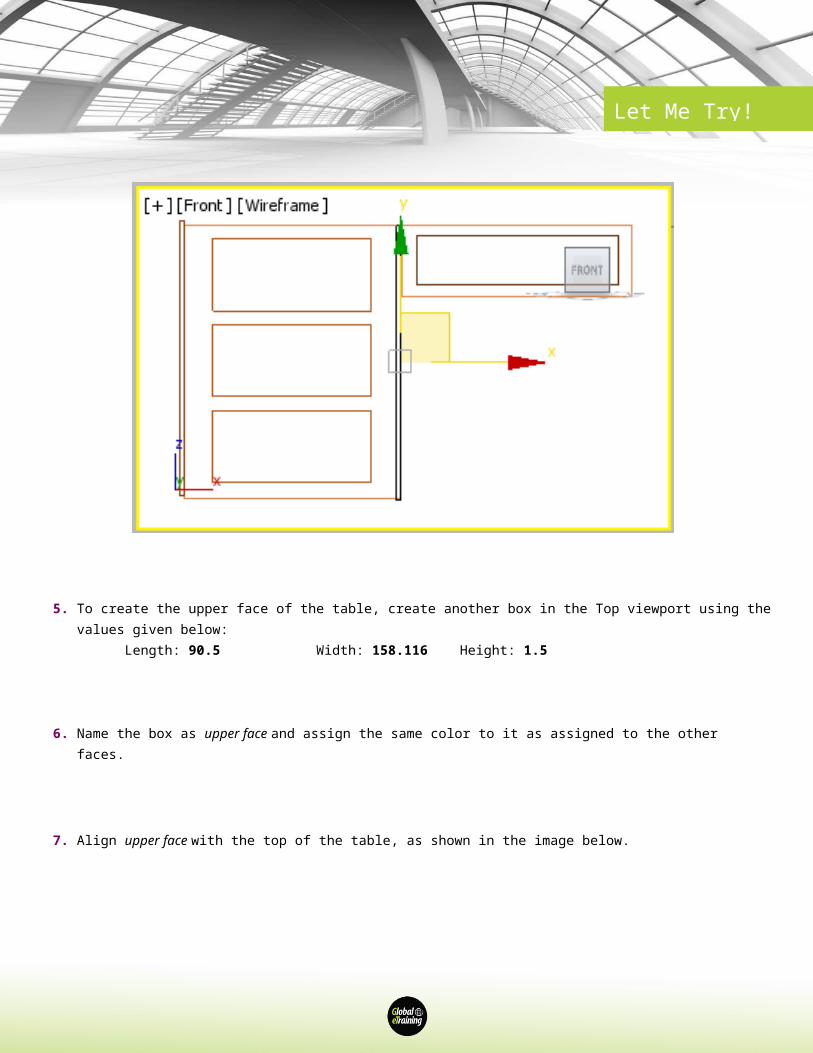
5. To create the upper face of the table, create another box in the Top viewport using the values given below:
Length: 90.5 Width: 158.116 Height: 1.5
6. Name the box as upper face and assign the same color to it as assigned to the other faces.
7. Align upper face with the top of the table, as shown in the image below.
Let Me Try!
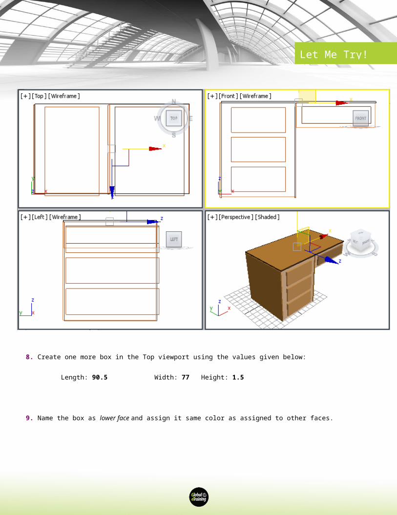
8. Create one more box in the Top viewport using the values given below:
Length: 90.5 Width: 77 Height: 1.5
9. Name the box as lower face and assign it same color as assigned to other faces.
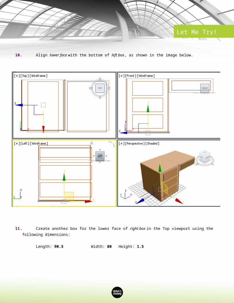
10.Align lower face with the bottom of left box, as shown in the image below.
Let Me Try!
11.Create another box for the lower face of right box in the Top viewport using the following dimensions:
Length: 90.5 Width: 80 Height: 1.5
12.Name the box as right lower face and assign the same color to it as assigned to the other faces.
13.Align right lower face at the bottom of right box, as shown in the image below.
Let Me Try!
14.Create a box for the right face of right box in the Left viewport using the following dimensions:
Length: 27.5 Width: 90 Height: 1.5
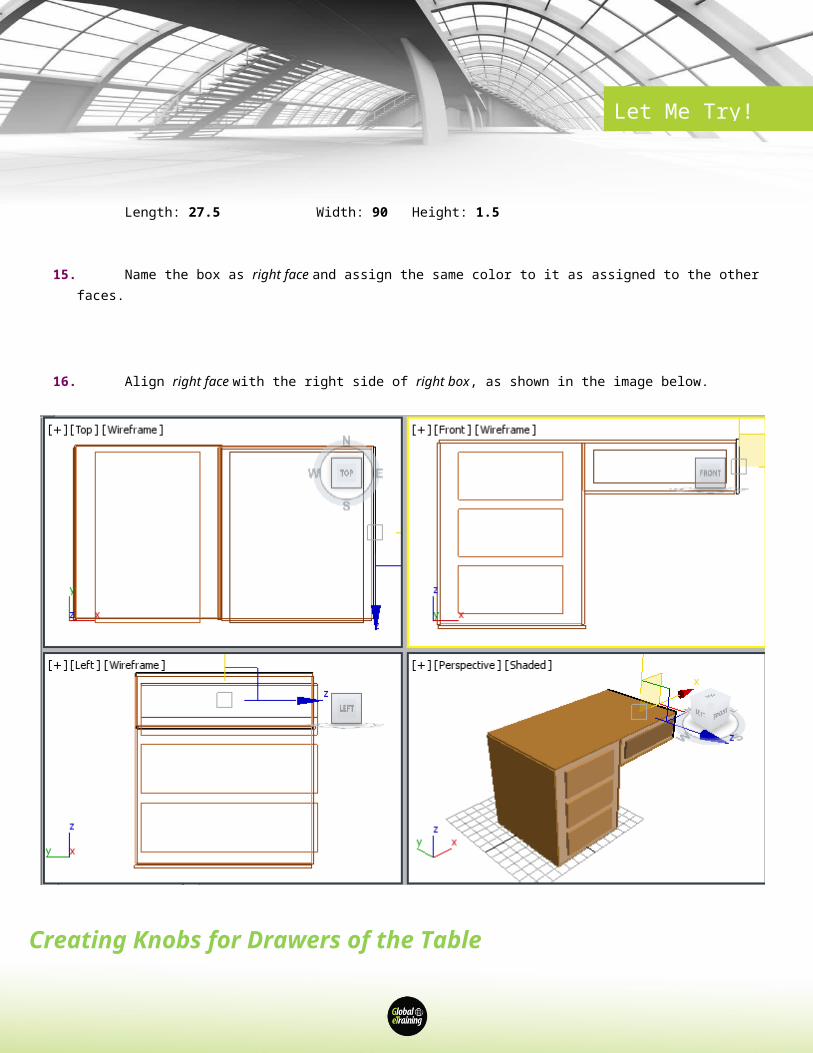
15.Name the box as right face and assign the same color to it as assigned to the other faces.
16.Align right face with the right side of right box, as shown in the image below.

Let Me Try!
Creating Knobs for Drawers of the Table
In this section, you will create a knob for one drawer. Next, you will copy the knob for the other drawers.
1. Choose the Sphere tool from Create > Geometry > Standard Primitives > Object Type rollout of the Command Panel.
2. Create a sphere in the Front viewport. In the Parameters rollout, enter 2.3 in the Radius spinner. Also, make sure the Smooth and Generate Mapping Coords check boxes and the Chop radio button are selected in this rollout.
3. Name the sphere as knob001 and use the color swatch to change its color to white.
Let Me Try!
4. Align knob001 with drawer001 in all viewports using the Select and Move tool, as shown in the image below.
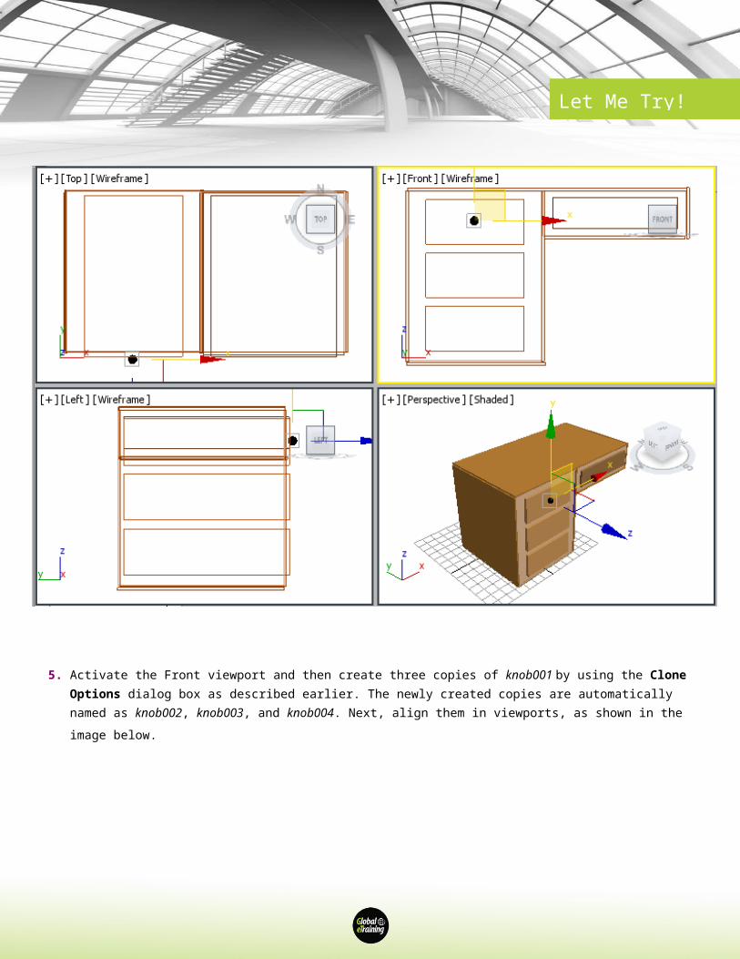
5. Activate the Front viewport and then create three copies of knob001 by using the Clone Options dialog box as described earlier. The newly created copies are automatically named as knob002, knob003, and knob004. Next, align them in viewports, as shown in the image below.
Let Me Try!
6. Set the view of the table in the Perspective viewport using the Orbit tool from the viewport navigation controls.
Changing Background Color of the Scene
In this section, you will change background color of the scene.
1. Choose Rendering > Environment from the menu bar; the Environment and Effects dialog box is displayed with the Environment tab chosen by default in this dialog box.
2. In the Background area of the Common Parameters rollout, choose the color swatch corresponding to the Color parameter; the Color Selector: Background Color dialog box is displayed. Select the white color and choose the OK button.
3. Close the Environment and Effects dialog box.
Let Me Try!
Saving and Rendering the Scene
In this section, you will save the scene that you have created and then render it.
1. Choose Save from the Application menu.
2. Activate the Perspective viewport. Next, choose the Render Production tool from the Main Toolbar; the Rendered Frame window is displayed with the final output of the table, as shown in the image below.