cp6 · cp6 computerfactstm put easy to use, ... tps tps • • tp3 + n .iiy n.1iy tp8 • ......
TRANSCRIPT
CP6
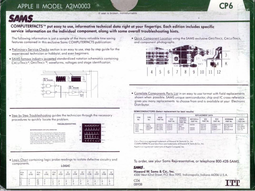
COMPUTERFACTSTM put easy to use, informative technical data right at your fingertips. Each edition includes specific service information on the individual component, along with some overall troubleshooting hints.
The following information is just a sample of the mC:1Y valuable time saving features contained in thi s exclusive Sams COMPUTERFACTS publication:
• Preli minar), Service Checks section is an easy to use, step by step guide for the
experienced technician o r hobbyist, and even beginners.
• SAMS famous industr), accepted standard ized notation schematics containing CiRcuITRAcE ®, GRIDTRACE TI .. , waveforms, voltages and stage identifi cation .
• Step~)' Step Troubleshooting guides the technician through the necessary
procedures to quickly locate the problem .
TROUBLESHOOTING
MICROPROC ESSOR CHIP (CPU) O PERATION
"~lly tnle IllOGeSSOI IS Il,ofICtlon'np O>r </'leek .,,!; t'le s'gnol-S on tht .oa'ess ' .nes (O,ns 10 l'lfV 2" 01 It U600, ii."'O the-o.la h"lI!Sto''!s oC' t l'll .. 56)u5<"IO".\Oo;I c.p.obeOt ol SCOpe . , . Qjj ~
DfOOe <5 uSed rel tl 10 the " lQ9'(. Choir! - I t)f Ille Co."ttl
le.a'''lis If ;Ii scope .s used the .... a"et:wl'-s 01' the ildOIM.S t "es tel<cept pons 22 a-'Id 23 ",I\IUI have nO$ ~ I'.al ,., Pc· .. e, U" mode) ' ''.cutd be $'I'n,lar to F'9""1! I Tl'e "''' ."1!'o,ms 01' ' he oata hnes s floulO be 5 ,m'~1 10 Figure :1
• Logic Chart containing logic probe readings to isolate defective circuitry and components.
LOGIC
PIN Ie PIN Ie PIN Ie IC IC Ie IC IC Ie IC NO. Ul00 NO. Ul00 NO. Ul02 Ul03 Ul04 UI 05 UI06 Ul07 Ul0S Ul09
1 P 21 P 1 L L l L l L l L 2 P 22 P 2 P P P f' P P P P } P 23 P 3 H H H H H H f' H
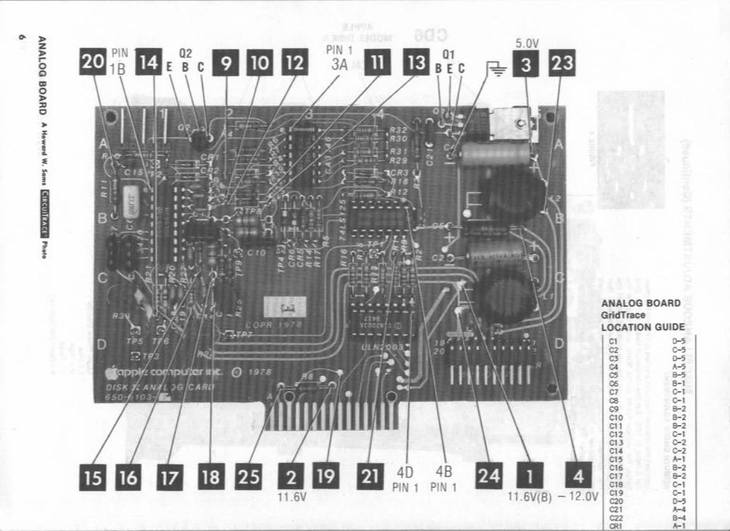
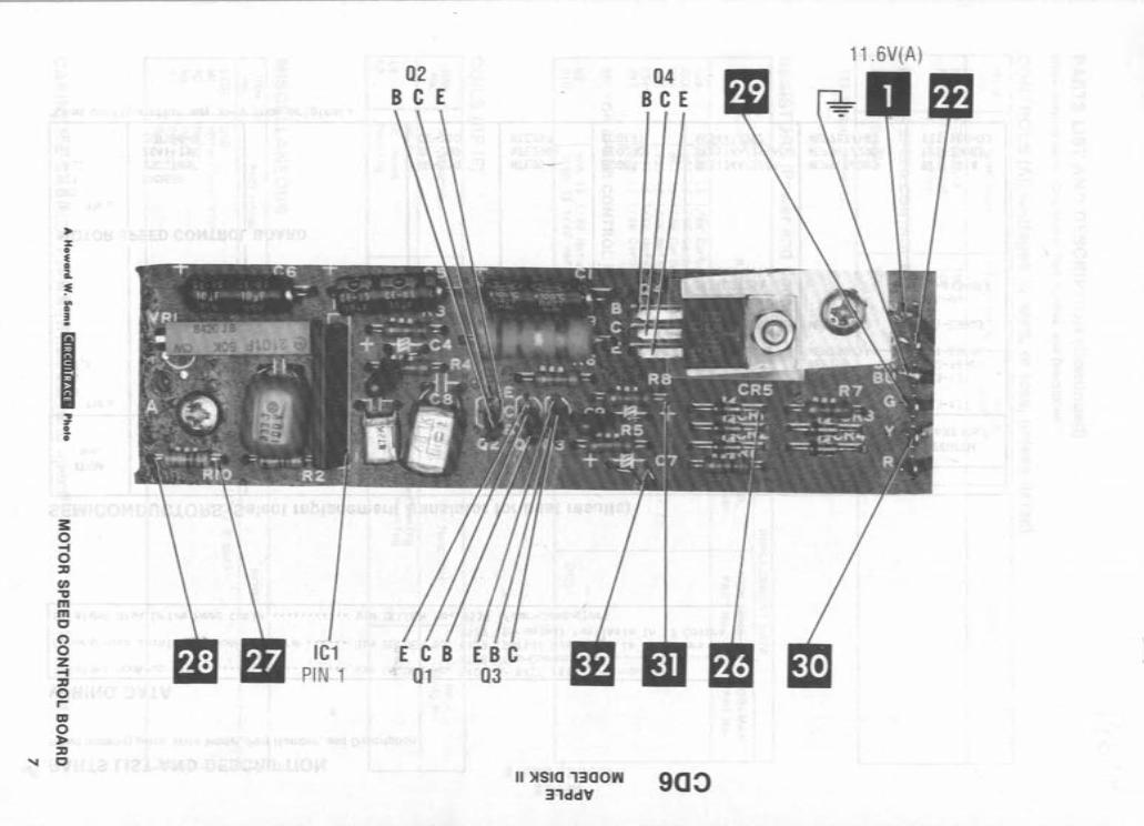
• Q uick Component Location using th e SAMS exclusive GRIDTRACE, CiRcuITRAcE, and component photographs.
(
I~C I~C' ;;;;;;a; ,'--iii I c-=:lllF.-
14
15
16
1 7
• ComRlete Components Parts List in an easy to use format with field rep lacements shown when possible. SAMS unique semiconductor, chip and IC cross-reference gives you many replacements to choose from and is available at your Electronic Distributor.
SEMICONDUCTORS (Select replacement for best results)
REPLACEMENT DATA ITEM TYPE MFGR. GENERAL No No PART No. ECG ElECTRIC MOTOROLA NTE
PART No PART No PART No. PART No
0102 ISS53 I 149-2'j76 ECG5 19 GE - 514 lN49J5 NTE519 0103 lN60FM 1149-2527 ECGl09 11'60 NTE1Q9 0201 It: 'OO4(p l201 -4205 ECG116 GE-504." lN40()4. NTE I 16 050 1 thr u 155,}} 1149-2576 ECG519 GE -514 lN4935 NTE519 OSC}
CtIlCU, TRACE.is a registered trademark of Howard W Sams & Co., Inc. COMPUTERFACTS and G. OTRACE are lrademarks of Howard W. Sams & Co., Inc.
Apple !~ 0 registered 'rodemark of Appl e Computer, Inc
RCA PART No.
51<.9091/177 SI0088 5K3312 5K9091/ 17 7
WORKMAN ZEtliTH PART No. PAP' ~o
'/lEP925/519 IOJ- I'. 1(£PI34/ 109 l OJ-Z9JOI 'liP' 157 21 2-76- 02 " EP925/519 103- 131
To order, see your Sams Representative, or telephone BOO-42B-SAMS.
SMt$'M Howard W. Sams & Co., Inc. 4300 West 62nd Street, P.O . Box 7092, Indianapolis, Indiana 46206 U.S.A.
CD6 08938 ITT
I OC' \ ...
',':., .. ~~ ~LS'O U
..... ', . l , J"" I' •
. }
. ' ." , ~. MTEHT '<"QlNG , .... ~nc " .. ~, /'
0'
'"
-, " .-------------~~------------~----~--~~----~~--~~--------~~--~~----------------~.!.~.'!!)':
~s.,.
,,, VLIoUOO) 0 4 -+ I • - ••••
~~~ __ --__ ------__ --~ __ ~ ____ ~~~------~------------~--------~--~----~~' ~'EA::> '
., ""nOI
"
r: J .---------~--~~~~------------~----------~~.~ .~~~------~~--~~--~----~~--~------~-".
'II .. "OT )..-------+----------------------'j;
10 Drt.'"
"~, , '~ \ I, '
\ ..
tI." HoUIU 1-4 :~.: t wIt tlA1'A\---...::..:......----:....,...:....--...,..;r-:::::...=='"'I '::,L......j-+--~+-+_-----'
"
\
:" L-----+-~~-c:---.:.:...---.,..--J t.: ,
~' " ' ~: o .... " ,,(0 :>,O'-~' ~-'-:-'i ~-}2..+-.....:.....:-l.....:........:...~:;.:...!;:;!!.,h:-::! .... ~-r;,=!b"Uh---, ". , ' ;)
~~ .Ct .1 ,i'l ,.". " '
I 'tI" . 1 U , " "" • I ,'. ~ ' H~ t : I. 4; '; ",.;,.,u. ~ 1Mt.1171 .i~.,
cb" ,, "" , .' . . ., .. "" , 1 , .. " I ' • " . " iO.~ . i4""' .. l~·""' ~C" , ' .. /'j ; ~ \:\ .. ~) ,'oF. •• : 1'" './ '. ' I ............ w.c n'" " ,
t -I I I _II • .. " ..... ,.. ,f .... i·. . ,' .... . . ~ 'I , . \,;.. ____ ~ ....... --..."J-.,..-. ...J I ' , ' ' " ....... ~_.~. ' . .. I • ,~ ••
• ' ~U , ~IO .\." I' ~ ' ,,' t l ' .. ' "',' . , •. j
.... ,. f.. ' .... : .,~: . \,:,:/:'\ O~O,~OOO1'tO t '/ ,1.' . '.: t ..,.'" l . ." ,,~' . ," \ (" .' ~, :' .' '1 " ' ~ . , " .. . ' " ', ., , . .. . . ~... . ,
4 • ' .. I ' ~ ... )".' t< .. ~ }.. .. . .: ', I ' : .. ~;t>~~( :' -,I~.~!..~.<,;','. \. ~:~,.:~'I 1<.: " , .. ~ . .I · ' :.:J I ' . ... ~:..:./ .. .., -"-" __ ...... "":'ill
..
I.
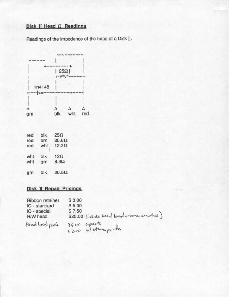
Plsk ][ Head 0 Readings
Readings of the impedence of the head of a Disk][.
1
1
1
1
~-------------- ~
12501 ~_VAVA ______ ---~
1 1 n4148 1 1 1 ~-----I<:==-----------------~-------I 1 1 1 1 1 1 1 1 ~ ~ ~ ~ grn blk wht red
red blk 250 red brn 20.60 red wht 12.20
wht blk 120 wht grn 8.30
grn blk 20.50
Pills ][ Bggill[ ~[I"iDgl
Ribbon retainer IC - standard IC - special RIW head
~w\O<J¥>~
$ 3.00 $ 5.00 $ 7.50 \ $25.00 {~ ~«J 1~04r~ ~ J ~l).0<' ~ L .\>2 .. 00 Ivl ~~.
RapYJ ~ ___ C_O_~ __ P_U_JJ_E_R0_A_C __ Ts_rM _________________ M_O_~_7_~E_ISK_1I
~
w~ "'0 Q. ... Q. w <1:0
o ==
co C o
PRELIMINA~Y SERVICE CHECKS
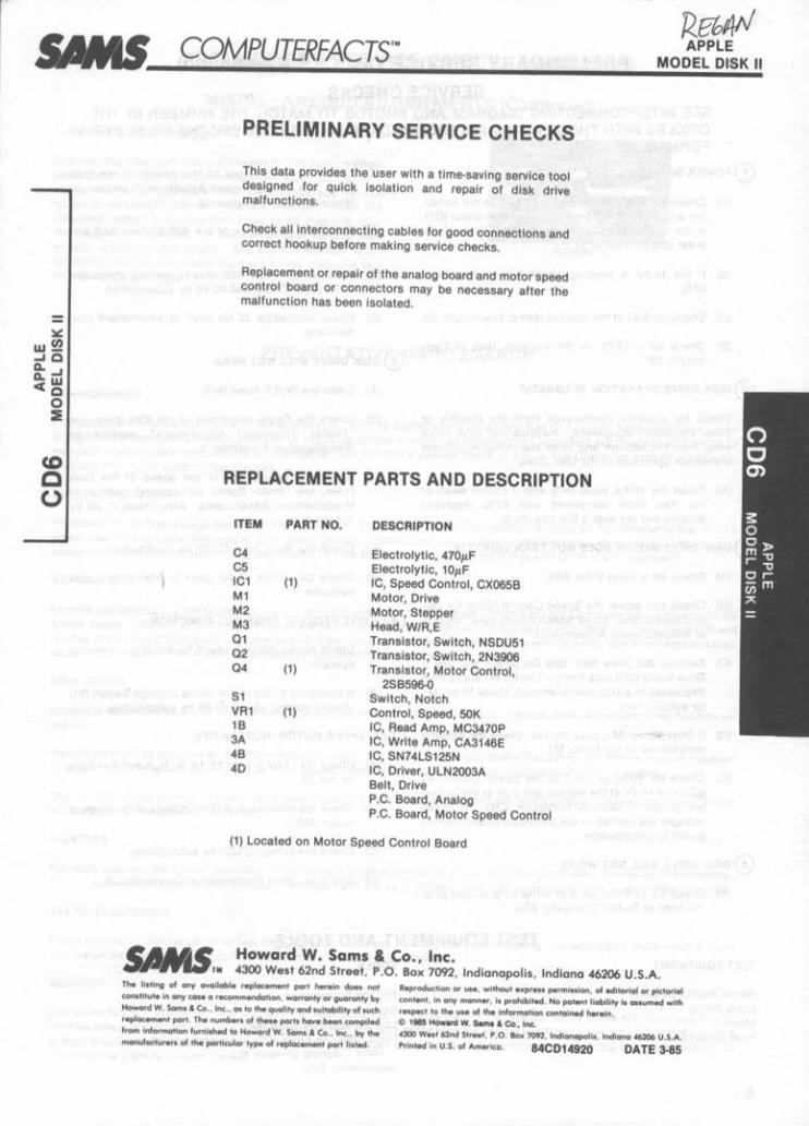
This data provides the user with a time-saving service tool designed for quick isolation and repair of disk drive malfunctions.
Check all Interconnecting cables for good connections and correct hookup before making service checks.
Replacement or repair of the analog board and motor speed control board or connectors may be necessary after the malfunction has been Isolated.
REPLACEMENT PARTS AND DESCRIPTION
ITEM
C4 C5 IC1 M1 M2 M3 01 02 04
S1 VR1 1B 3A 4B 40
PART NO.
(1)
(1)
(1)
DESCRIPTION
Electrolytic, 470!-,F Electrolytic, 10!-,F IC, Speed Control, CX065B Motor, Drive Motor, Stepper Head, W/R,E Transistor, Switch, NSDU51 Transistor, Switch, 2N3906 Transistor, Motor Control,
2SB596-0 Switch, Notch Control, Speed, 50K IC, Read Amp, MC3470P IC, Write Amp, CA3146E IC, SN74LS125N IC, Driver, ULN2003A Belt, Drive P.C. Board, Analog P.C. Board, Motor Speed Control
(1) Located on Motor Speed Control Board
Howard W. Sams & Co., Inc. 4300 West 62nd Street, P.O. Box 7092, Indianapolis, Indiana 46206 U.S.A.
Th. lI,tlng of any avallabl. r.plocement part herein does no' eonstltut. In any CQS. a recommendation, warranty or guaranty by Howard W. Saml & Ca . . Inc., 01 to the quality and suitability of luch replacement port . Th. numbert of these port. hoy. been compiled from Information furnllhed to Howard W, Sams & Co .. Inc., by the manufacturer. of the particular type of replacement port listed.
Reproduction or U'., without expre .. permission, of editorial or pictorial
content, In any manner, I, prohibited. No patent liability I, ollumed with respect to the uae of the Information contained herein .
e 188!1 How"" W. Sam ... Co., Inc. 4300 W •• t 62nd Str •• t, P,O. Box 7092, Indlonopolil, Indiana 46206 U.S.A. Printed In U,S, of America. 84CD14920 DATE 3.85
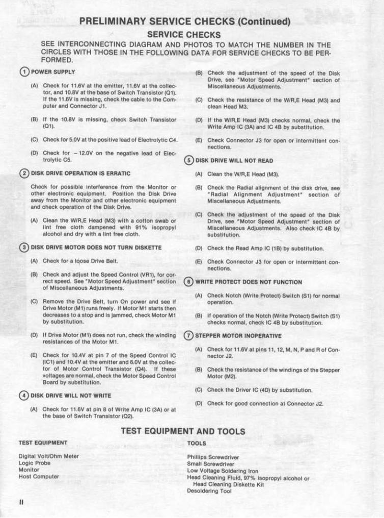
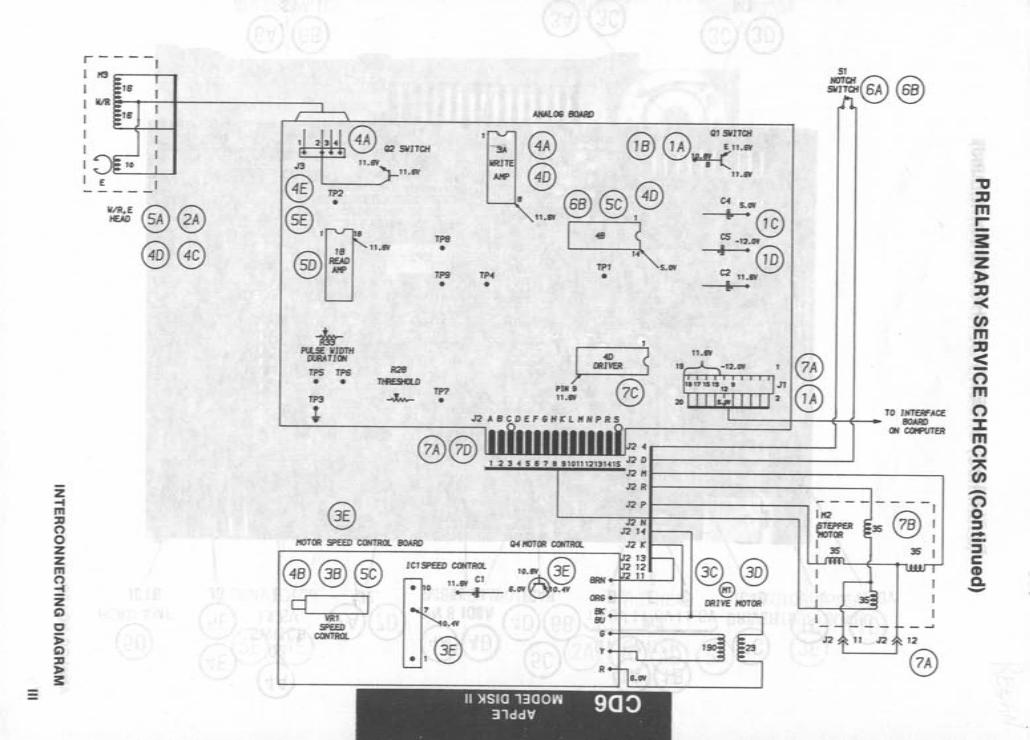
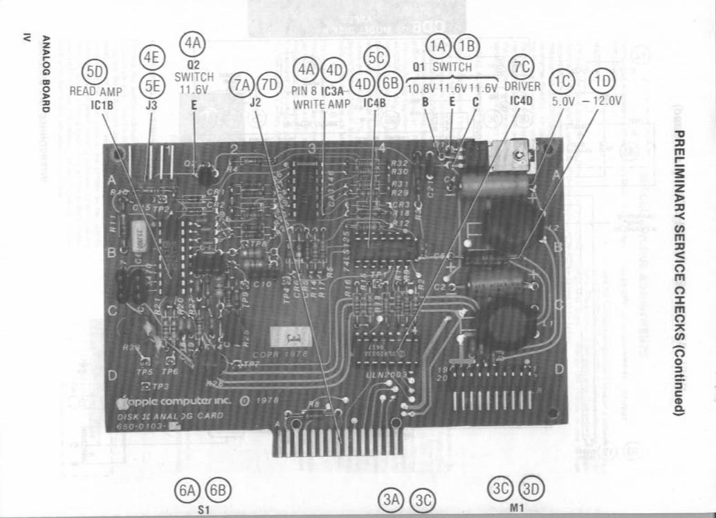
PRELIMINARY SERVICE CHECKS (Continued) SERVICE CHECKS
SEE INTERCONNECTING DIAGRAM AND PHOTOS TO MATCH THE NUMBER IN THE CIRCLES WITH THOSE IN THE FOLLOWING DATA FOR SERVICE CHECKS TO BE PER· FORMED.
o POWER SUPPLY
(A) Check for 11.6V at the emitter, 11.6V at the collector, and 10.8V at the base of Switch Transistor (01). If the 11.6V is missing, check the cable to the Computer and Connector J1.
(B) It the 10.8V Is missing, check Switch Transistor (01).
(C) Check for S.OV at the positive lead of Electrolytic C4.
(D) Check tor - 12.0V on the negative lead ot Electrolytic cs.
o DISK DRIVE OPERATION IS ERRATIC
Check for possible Interference from the Monitor or other electronic equipment. Position the Disk Drive away trom the Monitor and other electronic equipment and check operation of the Disk Drive.
(A) Clean the W/R,E Head (M3) with a cotton swab or lint free cloth dampened with 91 % Isopropyl alcohol and dry with a lint free cloth.
eD DISK DRIVE MOTOR DOES NOT TURN DISKETTE
(A) Check tor a I'lose Drive Belt.
(B) Check and adjust the Speed Control (VR1), for correct speed. See "Motor Speed Adjustment" section of Miscellaneous Adjustments.
(C) Remove the Drive Belt, turn On power and see if Drive Motor (M1) runs freely. If Motor M1 starts then decreases to a stop and Is jammed, check Motor M1 by substitution.
(D) If Drive Motor (M1) does not run, check the winding resistances of the Motor M1.
(E) Check for 10AV at pin 7 of the Speed Control IC (IC1) and 10AV at the emitter and 6.OV at the collector of Motor Control Transistor (04). If these voltages are normal, check the Motor Speed Control Board by substitution.
o DISK DRIVE WILL NOT WRITE
(A) Check for 11 .6V at pin 8 ot Write Amp IC (3A) or at the base of Switch TranSistor (02).
(B) Check the adjustment of the speed ot the Disk Drive, see "Motor Speed Adjustment" section of Miscellaneous Adjustments.
(C) Check the resistance of the W/R,E Head (M3) and clean Head M3.
(D) If the W/R,E Head (M3) checks normal, check the Write Amp IC (3A) and IC 4B by substitution.
(E) Check Connector J3 for open or intermittent connections.
o DISK DRIVE WILL NOT READ
(A) Clean the W/R,E Head (M3).
(B) Check the Radial alignment of the disk drive, see "Radial Alignment Adjustment" section of Miscellaneous Adjustments.
(C) Check the adjustment of the speed ot the Disk Drive, see "Motor Speed Adjustment" section of Miscellaneous Adjustments. Also check IC 4B by substitution.
(D) Check the Read Amp IC (1 B) by substitution.
(E) Check Connector J3 for open or Intermittent connections.
o WRITE PROTECT DOES NOT FUNCTION
(A) Check Notch (Write Protect) Switch (S1) for normal operation.
(B) If operation of the Notch (Write Protect) Switch (S1) checks normal, check IC 4B by substitution.
o STEPPER MOTOR INOPERATIVE
(A) Check for 11.6V at pins 11, 12, M, N, P and Rot Connector J2.
(B) Check the resistance of the windings of the Stepper Motor (M2).
(C) Check the Driver IC (40) by substitution.
(D) Check for good connection at Connector J2.
TEST EQUIPMENT AND TOOLS TEST EQUIPMENT
Digital Volt/Ohm Meter Logic Probe Monitor Host Computer
II
TOOLS
Phillips Screwdriver Small Screwdriver Low Voltage Soldering Iron Head Cleaning Fluid, 97% isopropyl alcohol or
Head Cleaning Diskette Kit . Desolderlng Tool
Z -t m ::u o o z z m o ~ z C)
c j; C) ::u l> 3:
r - - - -,
'113 , , ~--~~~----------------~ , , I
W@@
@@
rl---''-I=+-=+' @ Q2 SWITCH
-;&r PlLSE WIDTH
DtltATJOH
TPS TPS
• • TP3
+
n .IIY n.1IY
TP8 •
TP9
•
TP7 •
TP.f •
HOTOR SPEED CONTROl BOARO
®@® q I
VRI SPEED
CONTROl
ICI SPEED CONTROl
• 0 11.W CI
" .. 0.4V
.,@
Q ~ ~ QI SWITCH
~ ~ ~ En.1IY
~ ~ ~ ".IIY
n.1IY @) ® ~ S 14
TPI 5.0'1
J Pili I 11.1\'
•
11.11Y
C.f 5.0'1
.. "@ CS -'2.0'1
,I "@ C2 ".IIY .. "
@ @
TO IHTEllFACE ~------~---+~~~ BOARD
'O.IIY @ ti.I1V~O.4V
O~------------------~ OH~~
@@ @)
ORIVEHOTOR
II )lSIO 1300W 90::> 31dd"
"'0 :D m r--3: z :J> ::D -< en m ::D < -o m o :J: m o
" en -o o ~ -~ c CD Co -
<: :J> Z :J> r o C')
m o :J> ::D C
® READ AMP
IC1B
@ @ 02
@E SWITCH 11.6V
® @@ @@ 5C 01 SW~TCH @
@@ PINBIC3A-@@'iO.BV11.6V11.6V DRIVER ® @ J2 WRITE AMP IC4B BEe IC4D 5.0V -12.0V J3 E
@@ Sl @@ @@
Ml
""C II m r--3: z » II -< en m II < -o m o :l: m o " en -o o :::l -_. ~ c CD c. -
3: m o % l> Z (; :J> r .:... o '1:1
~ m
< ~
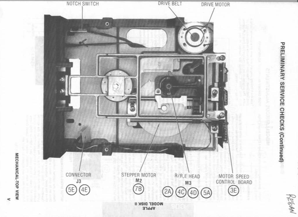
NOTCH SWITCH
CONNECTOR J3
®® STEPPER MOTOR
M2 RIR,E HEAD
M3
® @@@@ II )lSIO 1300W
31ddV
MOTOR SPEED CONTROL BOARD
®
"'U :0 m r--3: z » :0 -< (J) m :0 < -o m o :J: m o
" (J) -o o ~ -~ c (I) c. -
PRELIMINARY SERVICE CHECKS (Continued)
MISCELLAN EOUS ADJUSTMENTS
NOTE: Use a diagnostic diskette and a Dysan Analog Alignment Diskette 2:.:14/2A.
WARNING
It Is possible for a defective Disk Drive to write on or erase information on a diskette even if the diskette has been write protected. Check a questionable Disk Drive by first using a diskette that contains programs that have been duplicated on another diskette. Do not leave the alignment diskette in the drive while checking voltages and waveforms unless so Instructed in the alignment procedures. The test equipment may cause the disk drive circuits to erase sections of the alignment diskette even when the diskette is write protected with a write protect tab.
RADIAL ALIGNMENT ADJUSTMENT
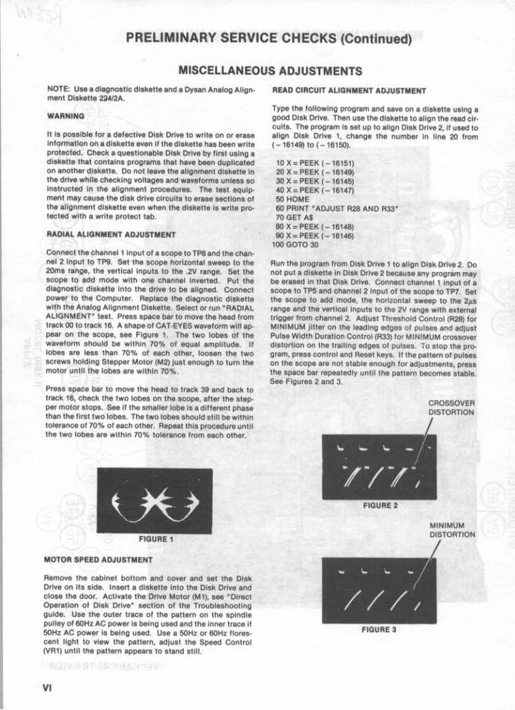
Connect the channel 1 Input of a scope to TP8 and the channel 2 input to Tpg. Set the scope horizontal sweep to the 20ms range, the vertical inputs to the .2V range. Set the scope to add mode with one channel Inverted. Put the diagnostic diskette into the drive to be aligned. Connect power to the Computer. Replace the diagnostic diskette with the Analog Alignment Diskette. Select or run "RADIAL ALIGNMENT" test. Press space bar to move the head from track 00 to track 16. A shape of CAT-EYES waveform will appear on the scope, see Figure 1. The two lobes of the waveform should be within 70% of equal amplitude. If lobes are less than 70% of each other, loosen the two screws holding Stepper Motor (M2) just enough to turn the motor until the lobes are within 70%.
Press space bar to move the head to track 39 and back to track 16, check the two lobes on the scope, after the stepper motor stops. See if the smalier lobe is a different phase than the first two lobes. The two lobes should still be within tolerance of 70% of each other. Repeat this procedure until the two lobes are within 70% tolerance from each other.
FIGURE 1
MOTOR SPEED ADJUSTMENT
Remove the cabinet bottom and cover and set the Disk Drive on its side. Insert a diskette into the Disk Drive and close the door. Activate the Drive Motor (M1), see "Direct Operation of Disk Drive" section of the Troubleshooting guide. Use the outer trace of the pattern on the spindle pulley of 60Hz AC power is being used and the inner trace if 50Hz AC power is being used. Use a 50Hz or 60Hz florescent light to view the pattern, adjust the Speed Control (VR1) until the pattern appears to stand still.
VI
READ CIRCUIT ALIGNMENT ADJUSTMENT
Type the foliowlng program and save on a diskette using a good Disk Drive. Then use the diskette to align the read circuits. The program is set up to align Disk Drive 2, if used to align Disk Drive 1, change the number in line 20 from (-16149) to ( - 16150).
10 X = PEEK (- 16151) 20 X = PEEK (-16149) 30 X = PEEK (-16145) 40 X = PEEK (-16147) 50 HOME 60 PRINT· ADJUST R28 AND R33" 70 GET A$ 80 X = PEEK (-16148) 90 X = PEEK (-16146)
100 GOTO 30
Run the program from Disk Drive 1 to align Disk Drive 2. Do not put a diskette in Disk Drive 2 because any program may be erased in that Disk Drive. Connect channel 1 input of a scope to TP5 and channel 2 input of the scope to TP7. Set the scope to add mode, the horizontal sweep to the 2p.s range and the vertical inputs to the 2V range with external trigger from channel 2. Adjust Threshold Control (R28) for MINIMUM jitter on the leading edges of pulses and adjust Pulse Width Duration Control (R33) for MINIMUM crossover distortion on the trailing edges of pulses. To stop the program, press control and Reset keys. If the pattern of pulses on the scope are not stable enough for adjustments, press the space bar repeatedly until the pattern becomes stable. See Figures 2 and 3.
FIGURE 2
FIGURE 3
CROSSOVER DISTORTION
MINIMUM DISTORTION
PRELIMINARY SERVICE CHECKS (Continued)
MISCELLANEOUS ADJUSTMENTS (Continued)
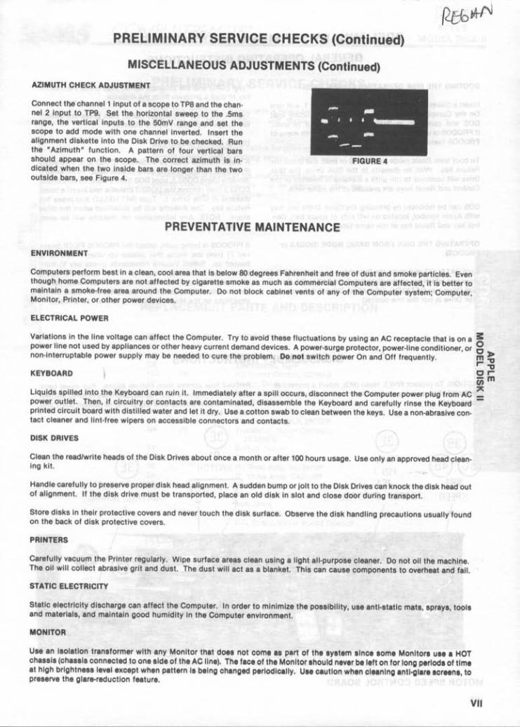
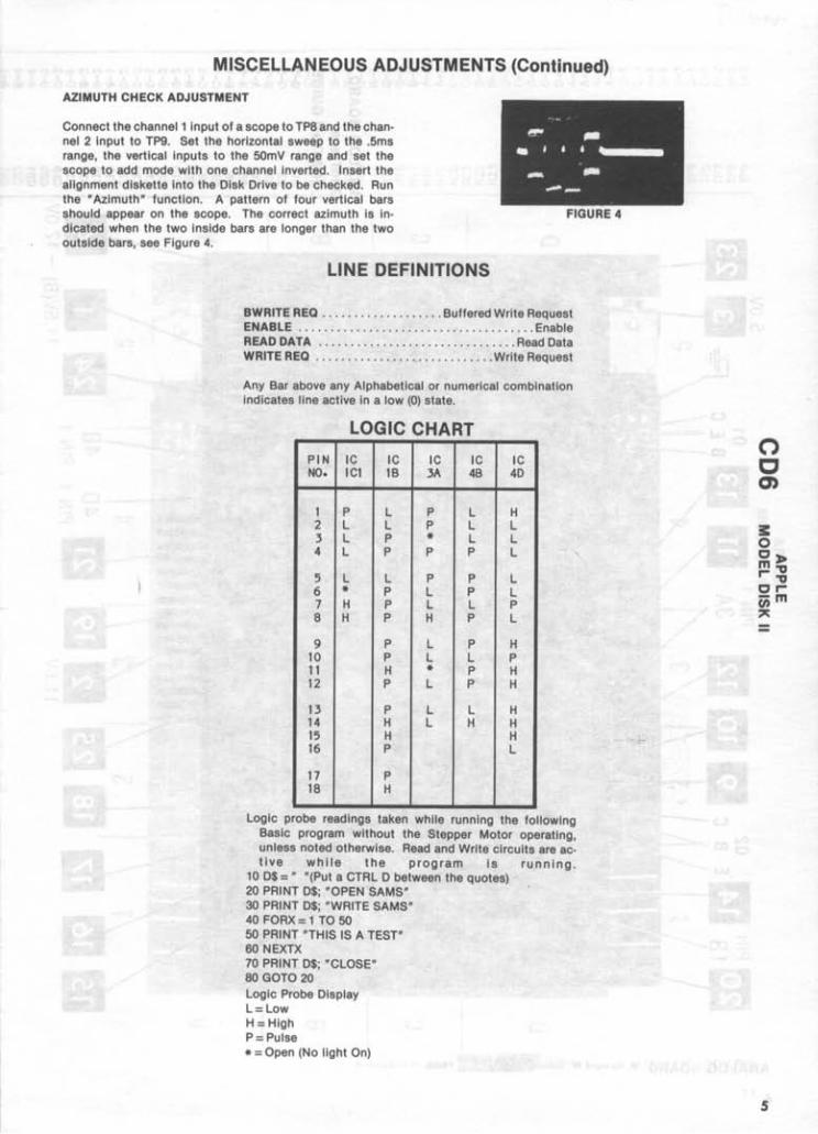
AZIMUTH CHECK ADJUSTMENT
Connect the' channel 1 Input of a scope to TP8 and the channel 2 Input to Tpg. Set the horizontal sweep to the .5ms range, the vertical Inputs to the 50mV range and set the scope to add mode with one channel Inverted. Insert the alignment diskette Into the Disk Drive to be checked. Run the "Azimuth" function. A pattern of four vertical bars should appear on the scope. The correct azimuth is indicated when the two inside bars are longer than the two outside bars, see Figure 4.
PREVENTATIVE MAINTENANCE
ENVIRONMENT
FIGURE 4
Computers perform best In a clean, cool area that is below 80 degrees Fahrenheit and free of dust and smoke particles. Even though home Computers are not affected by cigarette smoke as much as commerCial Computers are affected, It is better to maintain a smoke-free area around the Computer. Do not block cabinet vents of any of the Computer system; Computer, Monitor, Printer, or other power devices.
ELECTRICAL POWER
Variations In the line voltage can affect the Computer. Try to avoid these fluctuations by using an AC receptacle that is on a ~ power line not used by appliances or other heavy current demand devices. A power-surge protector, power-line conditioner, or g non-Interruptable power supply may be needed to cure the problem. Do not switch power On and Off frequently. m ~
r-."
KEYBOARD ~::;;
liquids spilled into the Keyboard can ruin it. Immediately after a spill occurs, disconnect the Computer power plug from AC ~ power outlet. Then, if circuitry or contacts are contaminated, disassemble the Keyboard and carefully rinse the Keyboard -printed circuit board with distilled water and let it dry. Use a cotton swab to clean between the keys. Use a non-abrasive con-tact cleaner and lint-free wipers on accessible connectors and contacts.
DISK DRIVES
Clean the read/write heads of the Disk Drives about once a month or after 100 hours usage. Use only an approved head cleaning kit.
Handle carefully to preserve proper disk head alignment. A sudden bump or jolt to the Disk Drives can knock the disk head out of alignment. If the disk drive must be transported, place an old disk in slot and close door during transport.
Store disks in their protective covers and never touch the disk surface. Observe the disk handling precautions usually found on the back of disk protective covers.
PRINTERS
Carefully vacuum the Printer regularly. Wipe surface areas clean using a light all-purpose cleaner. Do not oil the machine. The oil will collect abrasive grit and dust. The dust will act as a blanket. This can cause components to overheat and fall.
STATIC ELECTRICITY
Static electricity discharge can affect the Computer. In order to minimize the possibility, use anti-static mats, sprays, tools and materials, and maintain good humidity in the Computer environment.
MONITOR
Use an Isolation transformer with any Monitor that does not come a. part of the system since aome Monitors ua. a HOT chaaais (chaaais connected to one aide of the AC line). The face of the Monitor ahould never be left on for long p.rloda of time at high brlghtneaa level except when pattern Is being changed periodically. Use caution when cleaning anti-glare lerMnl, to preserve the glare-reduction feature.
VII
PRELIMINARY SERVICE CHECKS (Continued)
GENERAL OPERATING INSTRUCTIONS
BOOTING THE DISK OPERATING SYSTEM (DOS)
Insert a diskette containing DOS-Into Disk D[ive 1, and turn On the Computer. The Computer will automatically load DOS and come up In Basic mode, If DOS3.3 is used. If PRODOS is used the Computer will come up with menu of PRODOS features on the Monitor screen.
To boot from Basic mode, type PR#6 or IN#6 and press the Return key. With no diskette In the Disk Drive, the Disk Drive will continue to run until a diskette Is Inserted or the Control and Reset keys are pressed at the same time.
DOS can be rebooted by pressing the Open Apple key (key with Apple symbol, located on left Side of space bar), Con· trol key and Reset key at the same time.
OPERATING THE DISK FROM BASIC MODE (DOS3.3 or PRODOS)
Type CATALOG and press the Return key to get a list of the programs which are on the diskette. Type CATALOG, 01 for Disk Drive 1 or CATALOG, 02 for Disk Drive 2 If the current Disk Drive Is not the one desired.
Type LOAD and the program name, then press the Return key to load a program from the diskette.
Type SAVE and the program name, then press the Return key to save a program on the diskette.
USING BLANK DISKETTES
A blank diskette must be Initialized (DOS3.3) or formatted (PRODOS) before It can be used to save data. To Initialize a diskette using DOS3.3, boot DOS from a diskette containing .DOS3.3 then remove the DOS3.3 diskette and Insert a blank diskette In Disk Drive 1. Type INIT HELLO and press the Return key. The diskette will be initialized when the drive stops. NOTE: Any information on diskette will be overwritten.
If PRODOS Is being used, select the PRODOS FILER (press key F) from the menu that comes up when PRODOS is booted up. Select Volume commands (press key V) from the second menu that comes up. Then select Format A Volume (press key F) from the third menu that comes up. Insert the blank diskette Into the Disk Drive and follow the Instructions on the Monitor screen to format the diskette.
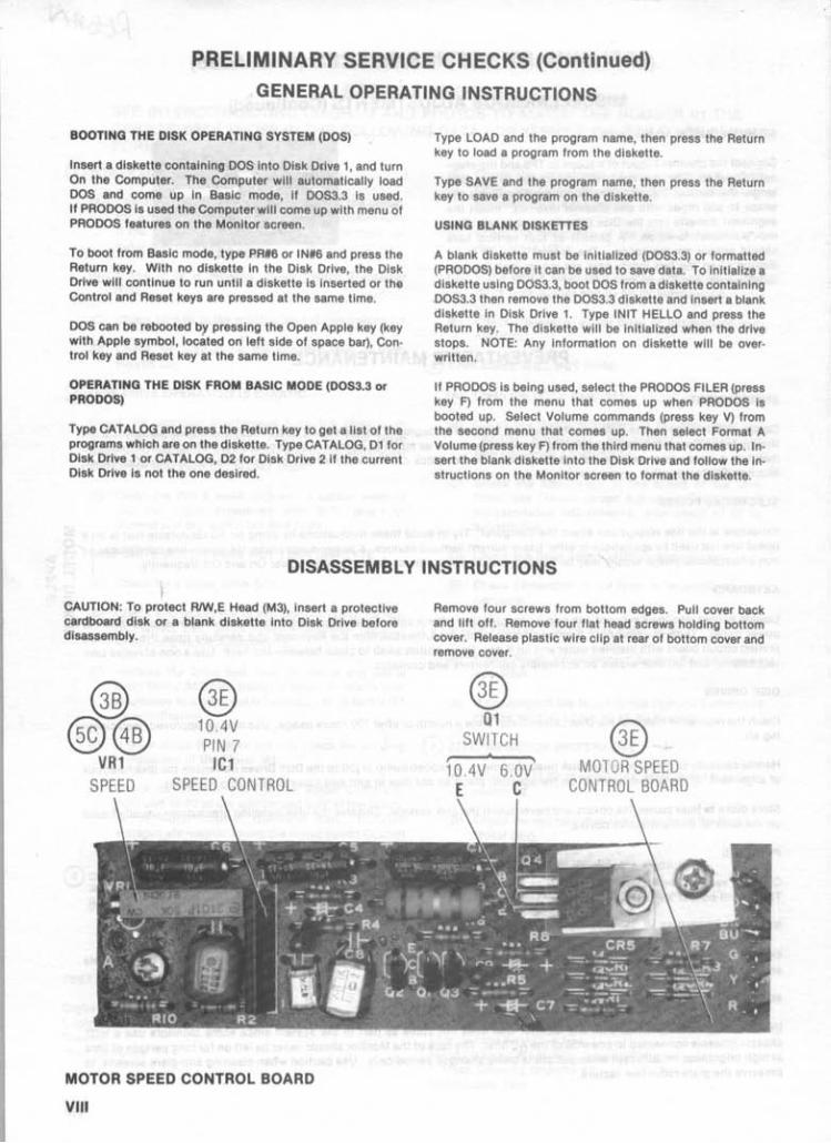
DISASSEMBLY INSTRUCTIONS , CAUTION: To protect RIW,E Head (M3), insert a protective cardboard disk or a blank diskette into Disk Drive before disassembly.
@ @@
VR1
® 10.4V PIN 7
IC1 SPEED CONTROL
MOTOR SPEED CONTROL BOARD
VIII
Remove four screws from bottom edges. Pull cover back and lift off. Remove four flat head screws holding bottom cover. Release plastic wire Clip at rear of bottom cover and remove cover.
® 01
SWITCH
10.4V 6.0V' C
® MOTOR SPEED
CONTROL BOARD
~eroNV ~ __ C __ ()_~ __ P_U_TJ_ER_n_A_C_~_5_TM _________________ M_O_~_7_~~_SK~1I
= ~
LLI~ .JQ Q..J Q. LLI c(Q
o :E
co C o
MODEL DISK II
SAFETY PRECAUTIONS See page 16.
PRELIMINARY SERVICE CHECKS ENCLOSED
INDEX Page Page
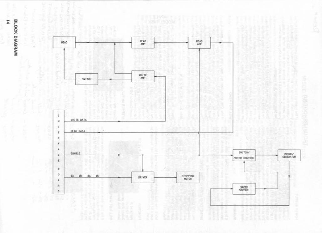
Block Diagram . . ... .. ....... .... .. . . . . . ... 14 Photos Disassembly Instructions . ... .. ......... . ... 16 Analog Board . ........ .. .... . . . .. . ... . . 6,11 General Operating Instructions .. . . . .. . .. .. . . 16 Mechanical-Top View . . .. . . .. .. .. . ... . ... 12 GridTrace Location Guide Motor Speed Control Board .. .. . . . .... ... 7,10
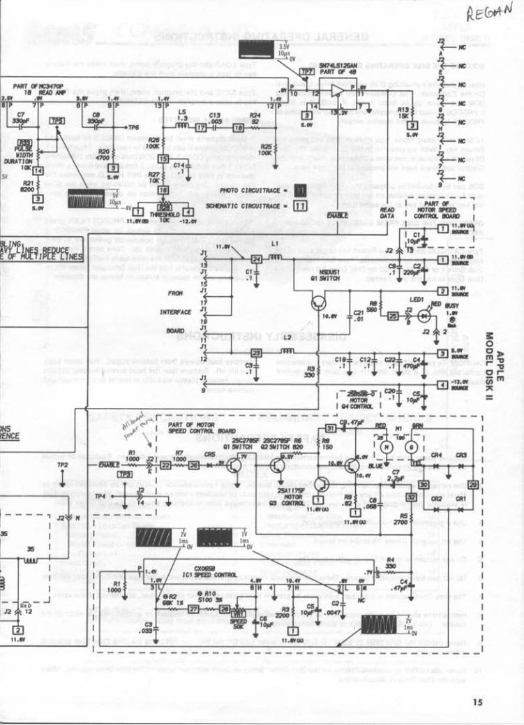
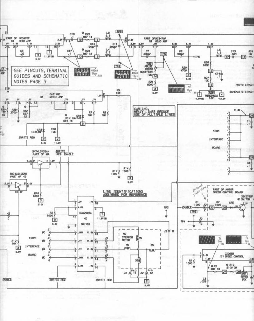
Analog Board ....... .. . .. . . .. .... . .. ... 6,11 Safety Precautions .. . . .. . .. ......... .. .. . . 16 Motor Speed Control Board ...... . ..... . . . 10 Schematic . .. .. . . . . . . .. . ... .. ... .... .... 2,15
Line Definitions . . . . .. .. . ....... .. .. .. ...... 5 Schematic Notes .. .. ...... . ... .... . . .. ... .. 3 Logic Chart . . . ...... . ... . . .... . ... .. .. . ... . 5 Terminal Guides and Pinouts . ... . . . ... . . . .. .. 3 Miscellaneous Adjustments .. . .. .. ...... .. . 4,5 Troubleshooting ... .............. . . . . .... . 13 Parts List .... . . . . ...... ... . .. . ........ .. . 8,9
Howard W. Sam. & Co., Inc. 4300 West 62nd Street, P.O. Box 7092, Indianapolis, Indiana 46206 U.S.A .
The lilting of any available replacement part herein do • • no. conltltut. In any co •• a recommendation, warranty or guaranty by Howord W. Sam. & Co .. Inc .. a. to the quality and .ultability of .uth r.plot.m.nt port. The numbers of th ••• port. hove been tomplled from information furnl.hed to Howard W. Sams & Co .. Inc .. by the manufocture" of the particular type of replacement port lilted.
Reproduction or use, without a.pr ... permlsllon , of edltorlol or pictorial tont.nt, In any mann.r , I. prohibited. No potent liability I. allumed with r •• pect to the u •• of the information contoln.d Mraln. e 1986 Howard W. Semi .. Co., Inc. .300 We. t 62nd SIr •• t, P.O. Box 7092. tndlanapoll. , Indiana ~206 U.S.A. Prlnled In U.S. of Am.rlta . 84CD14920 DATE 3.85
o c 0)
3: o OJ> m'V r-'V Or(iim ~
=
r - - --, , ~r---~-=~~~----------~--~~ , , , , , , ,
FROM
JNTERFACE
READ DATA
!/RJTE DATA
HOrCH DETECT
!/RJTE PROTECT
!HAII1
11.1'1 TPI
R4 1000
JI ~ 1~8(---- . 4V lOJts
OV READ DATA
I JI
I JI
3 JI
5
CR5 RIS IH4o-
1000 O!PX
51
SH14L5125AH PART OF 48
s.CI't
SEE PINOUTS, TERMINAL GUIDES AND SCHEMATIC NOTES PAGE 3
SH14LSI25AH PART OF 48
RI2 10K
RI8 1000
5.CI't
tIC FROM
tie JNTERFACE
~ 5.CI't
BOARO 10
R2 1000
5.CI't
JI J2 !HAII1
1 5
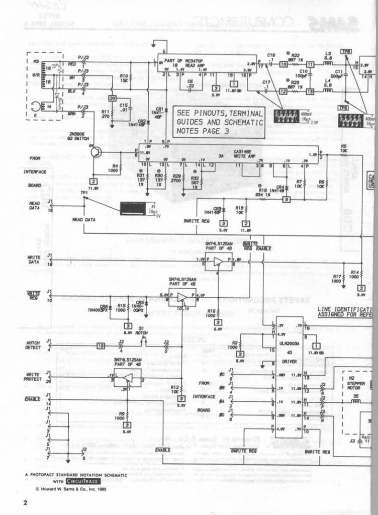
A 'HOTO'ACT STANDARD NOTATION SCHEMA TIC
WITH li'·Ai' ..... '.1 e Howard W. Sam. & Co., Inc. 1985
2
I
R7 10K
R6 10K
R5 10K
RI4 RI1 1000
1000
5.CI't
LINE IDENTIFICATI ASSIGNED FOR REF
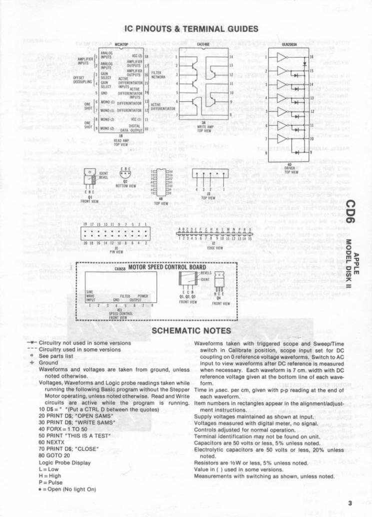
IC PINOUTS & TERMINAL GUIDES
AMPLIFIER {I INPUTS 2
OFFSET {3 DECOUPLING 4
ANALOG INPUTS
ANALOG INPUTS
GAIN SELECT GAIN SELECT
5 GND
MC3470P
VCC 12) 18 AMPLIFIER OUTPUTS 17 AMPLIFIER FILTER
ACTlV~UTPUTS 16 NETWORK
OIFFERENTIATOR 15 INPUTS ACTIVE OIFFERENTIATOR t4
INPUTS
CA3146E ULN2003A
,...----114 16
13 15
12
,...----111 14
10 13
ONE {6 SHOT 7
MONO (1) DIFFERENTIATOR 13} ACTIVE 6
MONO (IJ DIFFERENTIA TOR 12 DIFFERENTIATOR 7
12
{
8 ONE SHOT 9
MONO (2) VCC (1) 11 L-----::3
7""A ----' 11
MONO 12)
~IOENT ~8EVEL
E 8 C 01
FRONT VIEW
DIGITAL DATA OUTPUT 10
18 REAO AMP TOP VIEW
E B C e 02
80TTOM VIEW
13 11 9 7 5 3 I
1[114 2 1] ) 12 • 11 5 10 6 • 1 8
4B TOP VIEW
. I . . . . . 20 18 16 14 12 10 8 6 4 2
Jl PIN VIEW
WRITE AMP TOP VIEW
CfR=P 4 3 2 1
13 TOP VIEW
A8CDEFGHKLMNPRS .;; :; :; :; :; :; :; :; :; :; :; :; :; :; :; I
1 2 3 4 5 6 7 8 9 10 11 12 13 14 15 12
EDGE VIEW
40 DRIVER TOP VIEW
10
~ •....•.....•..•..•.............................•••••...•.• , cxom MOTOR SPEED CONTn .. A~PvELS ~
SINE WAVE INPUT
urn-u IOENT ~
ECB 8CE 01, 02, 03 04 FILTER POWER
GNO OUTPUT FRONT VIEW FRONT VIEW 4 ICI
SPEED CONTROL FRONT VIEW
6 7
_ ... --------_ ....... __ ........ --.......... _ ..... --_ ...... _.-SCHEMATIC NOTES
-- Circuitry not used in some versions - -- Circuitry used in some versions e See parts list + Ground
Waveforms and voltages are taken from ground, unless noted otherwise.
Voltages, Waveforms and Logic probe readings taken while running the following Basic program without the Stepper Motor operating, unless noted otherwise. Read and Write circuits are active while the program is running.
10 0$ =" "(Put a CTRL 0 between the quotes) 20 PRINT 0$; "OPEN SAMS" 30 PRINT 0$; "WRITE SAMS" 40 FORX= 1 TO 50 50 PRINT "THIS IS A TEST" 60 NEXTX 70 PRINT 0$; "CLOSE" 80 GOTO 20 Logic Probe Display L=Low H = High P= Pulse * = Open (No light On)
Waveforms taken with triggered scope and SweeplTlme switch in Calibrate position, scope input set for DC coupling on 0 reference voltage waveforms. Switch to AC input to view waveforms after DC reference is measured when necessary. Each waveform is 7 cm. width with DC reference voltage given at the bottom line of each waveform.
Time in ",sec. per cm, given with pop reading at the end of each waveform.
Item numbers In rectangles appear in the alignment/adjust-ment Instructions.
Supply voltages maintained as shown at input. Voltages measured with digital meter, no signal. Controls adjusted for normal operation. Terminal identification may not be found on unit. Capacitors are 50 volts or less, 5% unless noted. Electrolytic capacitors are 50 volts or less, 20% unless
noted. ReSistors are 1/2W or less, 5% unless noted. Value In ( ) used in some versions. Measurements with switching as shown, unless noted.
o c 0)
31': o O~ m"g r-"g Orcn m ~
=
3

MISCELLANEOUS ADJUSTMENTS
NOTE: Use a diagnostic diskette and a Dysan Analog Alignment Diskette 224/2A.
WARNING
It is possible for a defective Disk Drive to write on or erase Information on a diskette even if the diskette has been write protected. Check a questionable Disk Drive by first using a diskette that contains programs that have been duplicated on another diskette. Do not leave the alignment diskette in the drive while checking voltages and waveforms unless so instructed in the alignment procedures. The test equipment may cause the disk drive circuits to erase sections of the alignment diskette even when the diskette is write protected with a write protect tab.
RADIAL ALIGNMENT ADJUSTMENT
Connect the channel 1 input of a scope to TP8 and the channel 2 Input to TP9. Set the scope horizontal sweep to the 20ms range, the vertical Inputs to the .2V range. Set the scope to add mode with one channel inverted. Put the diagnostic diskette Into the drive to be aligned. Connect power to the Computer. Replace the diagnostic diskette with the Analog Alignment Diskette. Select or run "RADIAL ALIGNMENT" test. Press space bar to move the head from track 00 to track 16. A shape of CAT-EYES waveform will appear on the scope, see Figure 1. The two lobes of the waveform should be within 70% of equal amplitude. If lobes are less than 70% of each other, loosen the two screws holding Stepper Motor (M2) just enough to turn the motor until the lobes are within 70%.
Press space bar to move the head to track 39 and back to track 16, check the two lobes on the scope, after the stepper motor stops. See if the smaller lobe is a different phase than the first two lobes. The two lobes should still be within tolerance of 70% of each other. Repeat this procedure until the two lobes are within 70% tolerance from each other.
FIGURE 1
MOTOR SPEED ADJUSTMENT
Remove the cabinet bottom and cover and set the Disk Drive on its side. Insert a diskette into the Disk Drive and close the door. Activate the Drive Motor (M1), see "Direct Operation of Disk Drive" section of the Troubleshooting guide. Use the outer trace of the pattern on the spindle pulley of 60Hz AC power Is being used and the inner trace If 50Hz AC power is being used. Use a 50Hz or 60Hz flores· cent light to view the pattern, adjust lhe Speed Control (VR1) until the pattern appears to stand still.
4
READ CIRCUIT ALIGNMENT ADJUSTMENT (PUl.,£ VI p.rH g)VR4T1CM1) Type the following program and save on a diskette using a good Disk Drive. Then use the diskette to align the read circuits. The program Is set up to align Disk Drive 2, If used to align Disk Drive 1, change the number In line 20 from (-16149) to ( - 16150).
10X=PEEK( - 16151) ~eosC! (~ 1P~C;35 -1 20 X = PEEK (-16149) ~U>G"8 (P)A A") I -'"1~ 7
30X = PEEK(-16145) HOg-~ ('<JO:J rt-) J :p7r,7 4 = EK ( - 16141) .e.o~.., r ,'1:> O X PE ,.,. (rD r." ,"",,,,,(I> )
50 HOME 60 PRINT" ADJUST R28 AND R33" (!X)c:?tP(> ~ 70 GET A$ D 80 X=PEEK ( - 16148) tfco€6 [~ 90 X = PEEK (-16146) ~et:>ec;. C ~ Y)..A.)
100 GOTO 30
Run the program from Disk Drive 1 to align Disk Drive 2. Do not put a diskette In Disk Drive 2 because any program may be erased in that Disk Drive. Connect channel 1 input of a scope to TP5 and channel 2 Input of the scope to TP7. Set the scope to add mode, the horizontal sweep to the 2f.1.s range and the vertical Inputs to the 2V range with external trigger from channel 2. Adjust Threshold Control (R28) for MINIMUM jitter on the leading edges of pulses and adjust Pulse Width Duration Control (R33) for MINIMUM crossover distortion on the trailing edges of pulses. To stop the program, press control and Reset keys. If the pattern of pulses on the scope are not stable enough for adjustments, press the space bar repeatedly until the pattern becomes stable. See Figures 2 and 3.
FIGURE 2
FIGURE 3
CROSSOVER DISTORTION
MINIMUM DISTORTION
MISCELLANEOUS ADJUSTMENTS (Continued)
AZIMUTH CHECK ADJUSTMENT
Connect the channel 1 Input of a scope to TP8 and the chan· nel 2 Input to TP9. Set the horizontal sweep to the .5ms range, the vertical inputs to the 50mV range and set the scope to add mode with one channel inverted. Insert the alignment diskette Into the Disk Drive to be checked. Run the "Azimuth" function. A pattern of four vertical bars should appear on the scope. The correct azimuth is in· dicated when the two Inside bars are longer than the two outside bars, see Figure 4.
LINE DEFINITIONS
FIGURE 4
BWRITE REO . .................. Buffered Write Request ENABLE ............................ .... . .. . . Enable READ DATA ................... ... .. . . .. . .. Read Data WRITE REO ... . . ....................... Write Request
An,y Bar above any Alphabetical or numerical combination indicates line active In a low (O) state.
LOGIC CHART
PIN Ie Ie Ie Ie Ie NO. lei 18 3A 4B 40
1 P L P L H 2 L L P L L 3 L P * L L 4 L P P P L
5 L L P P L 6 * P L P L 7 H P L L P 8 H P H P L
9 P L P H 10 P L L P 11 H * P H 12 P L P H
13 P L L H 14 H L H H 15 H H 16 P L
17 P 18 H
Logic probe readings taken while running the following Basic program without the Stepper Motor operating, unless noted otherwise. Read and Write circuits are ac· tlve while the program is running.
10 0$ =" "(Put a CTRL 0 between the quotes) 20 PRINT 0$; "OPEN SAMS" 30 PRINT 0$; "WRITE SAMS" 40 FORX = 1 TO 50 50 PRINT "THIS IS A TEST" 60 NEXTX 70 PRINT 0$; "CLOSE" 80 GOTO 20 Logic Probe Display L=Low H = High P=Pulse * = Open (No light On)
o c 0)
~ o O~ m"tl r"tl or C;;m ,..
5
0- l> Z l> r-0 C)
m 0 » :JJ c
• % 0 ~ • A. ~ r ;I •
I .,. =r !t 0
11.6V
4D PIN 1 PIN 1
11.6V(B) -12.0V
ANALOG BOARD GridTrace LOCATION GUIDE
Cl C2 C3 C4 C5 C6 C7 C8 C9 CIO Cl l C12 C13 C14 C15 C16 C17 CIS C19 C20 C21 C22 CRI
0-5 C-5 0-5 A-5 8-5 8-1 C-l C-l B-2 B-2 B-2 C-l C-2 C-2 A-I 8-2 B-2 C-l C-l 0-5 A-4 B-4 A-I
I 3: o -f o ::D en "1J m m o o o Z -f ::D o r-aJ o ~ ::D
.... 0
IC1 PIN 1
04 BeE
II >ISla 130011\1 90:> 31ddV
11 .6V(A)
· CD PARTS LIST AND DESCRIPTION When ordering parts, state Model, Part Number, and Description
WIRING DATA Sh ielded Hook-up Wire •••••••••••••••••••• Use BELDEN No. 8401 or 8421 (Slng le-Conductor) I
8208 (Two-Conouctor) General-use Unshielded Hook-up Wire •••••• Use BELDEN No. 8529 (So l id) Available In 13 Colors
8522 (Stranded) Ava i lab le In 13 Colors Shielded Disk Drive Head Cable ••••••••••• Use BELDEN No. 9534 (Four-Con~uctor)
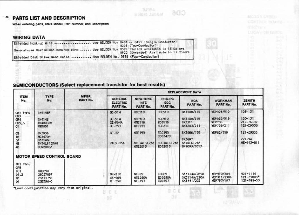
SE~ICONDUCTORS (Select replacement transistor for best results)
REPLACEMENT DATA ITEM TYPE MFGR. No. No. PART No. GENERAL NEW·TONE PHILIPS
RCA ELECTRIC NTE ECG PART No. PART No. PART No. PART No.
CRI thru lN4148F ~-514 NTE519 ECG519 SK3100/519 au CR4 lN4148 ~-514 NTE519 ECG519 SK3100/519 CR5,6 lN4003PX ~-504A NTE116 ECG116 SK3311 01 NSDU51 ~-253 NTE211 ECG211 SK3203/211
q2 2N3906 ~-82 NTE159 ECG159 SK3466/159 lB foC347OP ECG3470 3A CA3146E SK3697 48 SN74LS125AN 74LS125A NTE74LS 1 25A ECG74LS 125A SK74LS125A 4D ULN2003A NTE2013 ECG2013 SK9093/2013
MOTOR SPEED CONTROL BOARD
CRI thru CR5 ICI CX0658 01 , 2 2SC2785F ~-210 NTE85 ECG85 SK3124A/289A Q3 2SAI175F ~-269 NTE290A ECG290A SK3114A/290A Q4 293596-0 ~-250 NTE197 ECG197 SK3441/292
*Lead configuration may vary from original . I
WORKMAN ZENITH PART No. PART No.
WEP925/519 103-131
WEP925/519 103-131 WEP156 212-76-02 WEP759/211 121-Z9056
WEP62/159 121-Z9003
221-94 HE-443-811
WEP91 0/289 921-1114 WEP911/290A 121-Z9003* WEP7571197 121-988-03
PARTS LIST AND DESCRIPTION (Continued) When ordering parts, state Model, Part Number, and Description
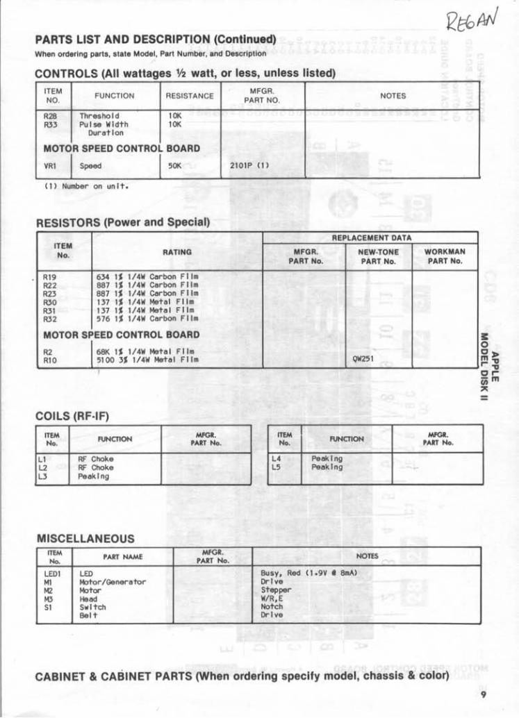
CONTROLS (All wattages Y2 watt, or less, unless listed)
ITEM FUNCTION RESISTANCE
MFGR. NOTES NO. PART NO.
R2B Threshold 10K R33 Pulse WIdth 10K
DuratIon
MOTOR SPEED CONTROL BOARD
VRI I Speed l sOt< 2101P (1)
(1) Number on unIt.
RESISTORS (Power and Special) REPLACEMENT DATA
ITEM No. RATING MFGR. NEW·TONE WORKMAN
PART No. PART No. PART No.
R19 634 1% \/4W Carbon FIlm R22 BB7 1% 1/4W Carbon FIlm R23 BB7 1% 1/4W Carbon FIlm R30 137 1% 1/4W Metal FIlm R31 137 1% 1/4W Mete I FIlm R32 576 1% 1/4W Carbon FIlm
MOTOR SPEED CONTROL BOARD
R2 6BK 1% 1/4W Metal FIlm RIO 5100 3% \/4W Metal FIlm QW251
COILS (RF·IF)
ITEM FUNCTION MFGR. No. PART No.
ITEM FUNCTION MFGR.
No. PART No.
Ll RF Choke L4 PeakIng L2 RF Choke L5 PeakIng L3 PeakIng
MISCELLAN EOUS ITEM
PART NAME MFGR. NOTES
No. PART No.
LEDI LED Busy, Red (\.9V • BmA) Ml Motor/Generator DrIve M2 Motor Stepper M3 Head W/R,E SI SwItch Notch
Belt DrIve
CABINET & CABINET PARTS (When ordering specify model, chassis & color)
E o O~ m." r-." OrC;;m ~
9
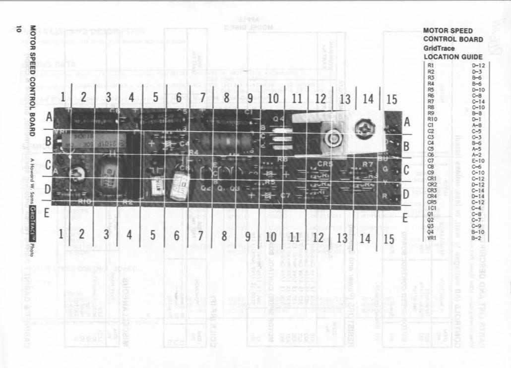
- i: MOTOR SPEED 0 0 CONTROL BOARD
-4 0 GridTrace :z:I f/) LOCATION GUIDE '1J R1 0-12 m m R2 0-3 C R3 8-6 0 R4 6-6 0 R5 0-10 Z -4 1 2 3 4 5 6 7 8 9 10 11 12 13 14 15 R6 C-8
:z:I R7 C-14 0 R8 C-10 r- R9 8-8 m R10 0-1 0 C1 A-8 » :z:I
C2 C-5
C C3 C-3 C4 B-6 C5 A-5 C6 A-2 C7 E-10
)- C8 C-6 :I: 0 C9 C-10 ~ g CR1 C-12 c.. CR2 0-12 :E CR3 C-14 VI CR4 0-14 0 CR5 C-12 3 .. IC1 C-4
I E E Q1 C-8 Q2 C-7 Q3 C-9
1 2 3 4 5 6 7 8 9 10 11 12 Q4 B-10
13 14 15 VR1 B-2
~ J 0 0
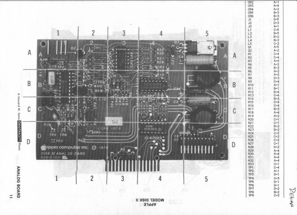
CR2 A-I CR3 A-4 CR4 A-2 CR5 B-3 CR6 B-3 JI D-5 J2 D-3 J3 A-I
1 2 3 4 5 L1 C-5 L2 B-5 L3 B-2 L4 B-2 L5 C-2 QI A-5
A Q2 A-2
A RI C-4 R2 C-4 R3 A-4 R4 A-2 R5 B-3 R6 A-2 R7 A-2 RB D-3
B B R9 C-4 RIO A-I RII B-1
> RI2 B-4 J: R13 C-4 0 ~
RI4 B-3 0 RI5 C-4 a. :E C
RI6 C-4
C RI7 B-3 V> RIB A-4 0 3 RI9 A-2 ..
I R20 C-I R21 C-l R22 B-2 R23 B-2 R24 C-2
0 R25 C-2
." R26 C-2
::r 0 R27 C-l 0 0 R2B D-2
R29 A-4 R30 A-4 R31 A-4 R32 A-4
» ' R33 C-I
Z TPI C-4 » TP2 A-I r
1 2 TP3 D-I
0 3 4 5 TP4 C-, C')
TP5 D-I CD 0
TP6 D-I » TP7 D-2
~ ::D TPS B-2 C TP9 C-2
II )ISla 13aow 31ddY ~
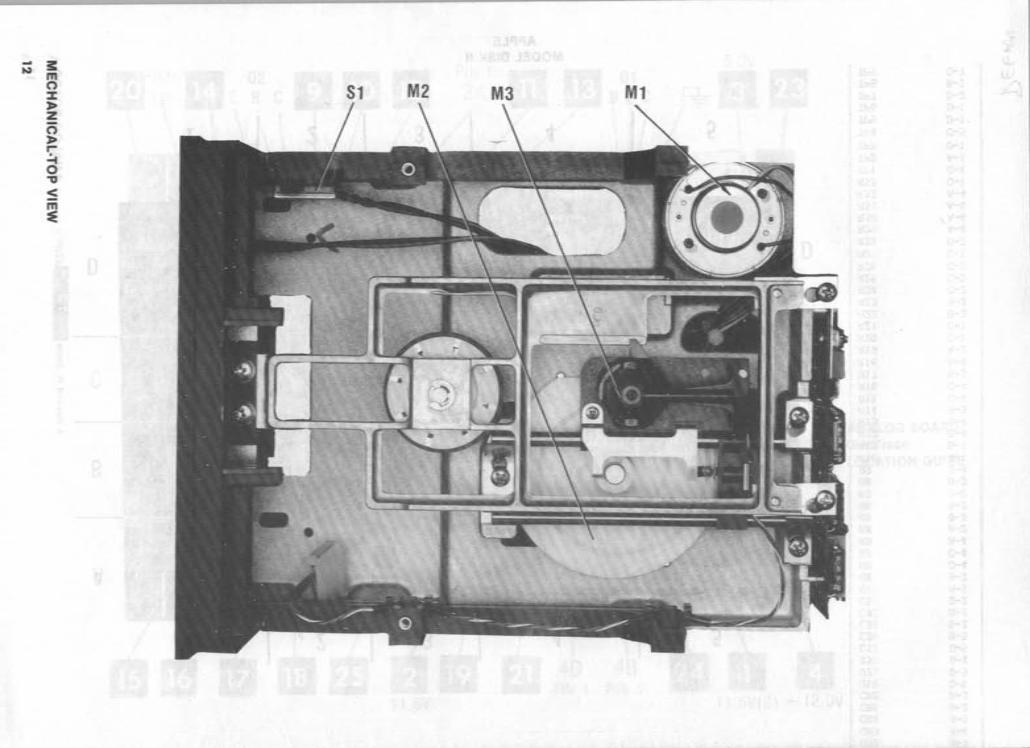
- 3: ~ m 81 M2 M3 Ml 0
% :J> Z C5 :J> r-.:... 0 "'0
~ m ~
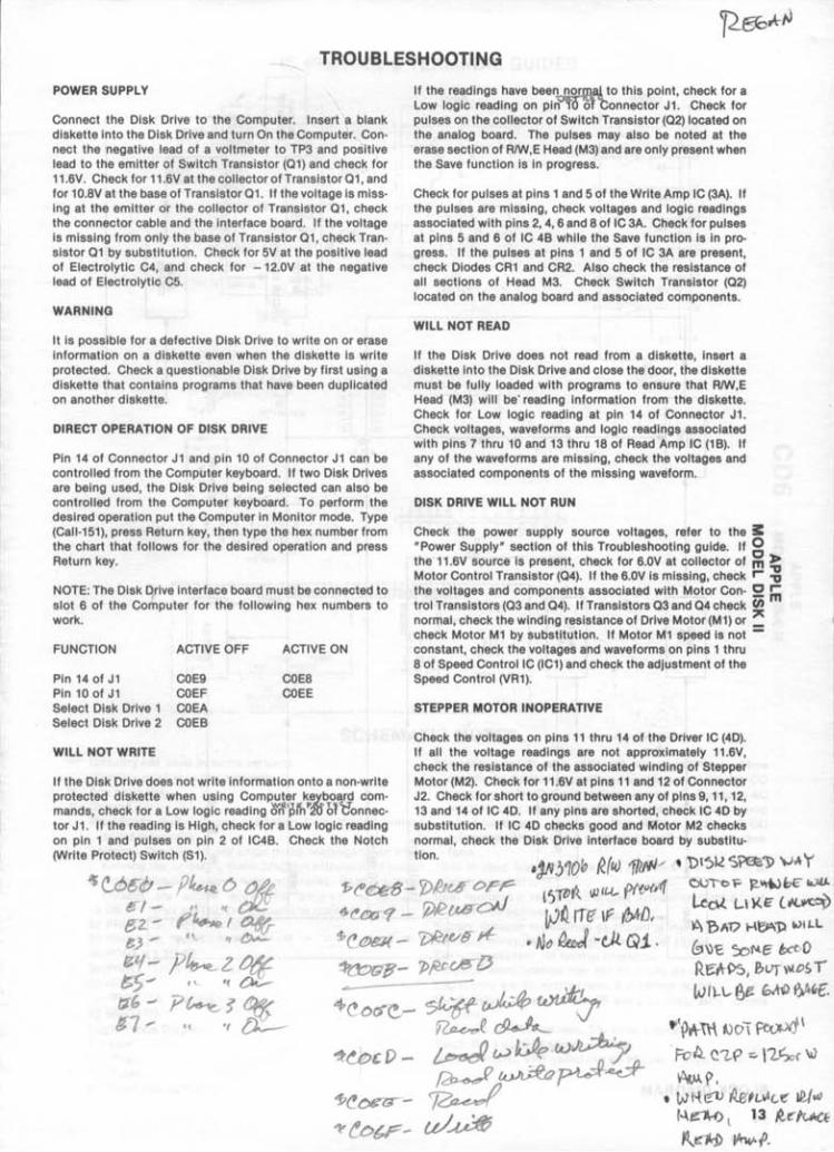
TROUBLESHOOTING
POWER SUPPLY
Connect the Disk Drive to the Computer. Insert a blank diskette Into the Disk Drive and turn On the Computer. Connect the negative lead of a voltmeter to TP3 and positive lead to the emitter of Switch Transistor (01) and check for 11.6V. Check for 11.6V at the collector of Transistor 01, and for 10.8V at the base of Transistor 01. If the voltage Is missIng at the emitter or the collector of Transistor 01, check the connector cable and the interface board. If the voltage Is missing from only the base of Transistor 01, check Transistor 01 by substitution. Check for 5V at the positive lead of Electrolytic C4, and check for -12.0V at the negative lead of Electrolytic C5.
WARNING
It is possible for a defective Disk Drive to write on or erase information on a diskette even when the diskette is write protected. Check a questionable Disk Drive by first using a diskette that contains programs that have been duplicated on another diskette.
DIRECT OPERATION OF DISK DRIVE
Pin 14 of Connector J1 and pin 10 of Connector J1 can be controlled from the Computer keyboard. If two Disk Drives are being used, the Disk Drive being selected can also be controlled from the Computer keyboard. To perform the desired operation put the Computer In Monitor mode. Type (Call-151), press Return key, then type the hex number from the chart that follows for the desired operation and press Return key.
NOTE: The Disk Drive interface board must be connected to slot 6 of the Computer for the following hex numbers to work.
FUNCTION ACTIVE OFF
Pin 14 of J1 COE9 Pin 10 of J1 COEF Select Disk Drive 1 COEA Select Disk Drive 2 COEB
WILL NOT WRITE
ACTIVE ON
COE8 COEE
If the Disk Drive does not write information onto a non-write protected diskette when using Computer k~'y.board commands, check for a Low logic reading lrrf'pll1'2trM'e'onnector J1. If the reading is High, check for a Low logic reading on pin 1 and pulses on pin 2 of IC4B. Check the Notch (Write Protect) Switch (S1).
If the readings have been norlBal to this point, check for a Low logic reading on pln"'fO ol"tonnector J1. Check for pulses on the collector of Switch Transistor (02) located on the analog board. The pulses may also be noted at the erase section of RIW,E Head (M3) and are only present when the Save function is in progress.
Check for pulses at pins 1 and 5 of the Write Amp IC (3A). If the pulses are missing, check voltages and logic readings associated with pins 2, 4, 6 and 8 of IC 3A. Check for pulses at pins 5 and 6 of IC 4B while the Save function is in progress. If the pulses at pins 1 and 5 of IC 3A are present, check Diodes CR1 and CR2. Also check the resistance of all sections of Head M3. Check Switch Transistor (02) located on the analog board and associated components.
WILL NOT READ
If the Disk Drive does not read from a diskette, insert a diskette Into the Disk Drive and close the door, the diskette must be fully loaded with programs to ensure that RIW,E Head (M3) will be'readlng information from the diskette. Check for Low logic reading at pin 14 of Connector J1. Check voltages, waveforms and logic readings associated with pins 7 thru 10 and 13 thru 18 of Read Amp IC (1 B). If any of the waveforms are missing, check the voltages and associated components of the missing waveform.
DISK DRIVE WILL NOT RUN
Check the power supply source voltages, refer to the I: ·Power Supply· section of this Troubleshooting guide. If g the 11 .6V source Is present, check for 6.0V at collector of m ?:; Motor Control Transistor (04). If the 6.0V is missing, check r "0 the voltages and components associated with Motor Con- !!2 In trol Transistors (03 and 04). If Transistors 03 and 04 check ~ normal, check the winding resistance of Drive Motor (M1) or _ check Motor M1 by substitution. If Motor M1 speed is not -constant, check the voltages and waveforms on pins 1 thru 8 of Speed ControllC (IC1) and check the adjustment of the Speed Control (VR1).
STEPPER MOTOR INOPERATIVE
Check the voltages on pins 11 thru 14 of the Driver IC (40). If all the voltage readings are not approximately 11.6V, check the resistance of the associated winding of Stepper Motor (M2). Check for 11.6V at pins 11 and 12 of Connector J2. Check for short to ground between any of pins 9,11,12, 13 and 14 of IC 40. If any pins are shorted, check IC 40 by substitution. If IC 40 checks good and Motor M2 checks normal, check the Disk Drive interface board by substitu-
tion. .jN!J10b R(fJ.) 1/lfIJ'/ ~ '\)(~Il S'i'as'J> \JA Y 'P~Cefj- y)hG8 OrP ({ ru. pft<J(If( Ol""'b? ~~bE" Ca)I.I.. .
~~? _ r;;R{..ld~ lSl1> w ~ l-\)(E Li<.~ 1 ~~ Ire If (!;ltD, ~ ?>AV H~1) ~IL.L I
$(! e>g]( - 7;lCtV8,.{- • tJ" ~ -t,U. Qi . G1\)'E x>1'le ~o ~(t:)UB'- 7>fU:~lJ Re:rH>5, P.1VfVlloS'
cr:../" ':./.J1- .I ~ 12.. , . 'if J:1i.!.-_ tv r \-1..- f>e tp..W &A~f-<tJ.(! C>($(!,,- ./~~ ~ -- v'
~ ~ fl(~~ fJO\ ~~\ \
~u:>, f) - ~ w tJe w~ . Fo~ Q1..P ::.\1.tSo( \i) ~~~~ ~P. ~ • t,.JHe:1J iJ.zhlAC-f! ~fw uJ~ r4~ l 13 ~~'u.cE
~tdri> .JItw. (J.
l 1 [ 1 t£Al) READ 1 1 I 1 AIf> 1- 1
READ AIf>
1
l l WRITE
SVITCH AIf>
1 1
.---I
N WRITE DATA
T
E READ DATA
R
F
A
C ENABLE .1 SWITCH/ 1 E
I MOTOR! I }tOT OR CONTROL I GENERATOR
B t /
0 ~A ~ oc !rID I 1 A 1
DRIVER 1 STEPPING l I 1 /1OTOO
R
D
I SPEED 1 '-- 1 CONTROL I
TP2
1
I----~ J :35 1
i 35
1 1 1 1 1 1 1 1 1 1 1 1
FROH
IHTfWACE
PHOTO CIRCUJTRACE •
RACE • ~TlC CIRCUIT
Jf.' __ _
9
• [i]
)-'"' r -;..., " "":::. ..... ,..,.,. ,. »'",''' I ...", "'" """"" .... ,"" '" 'if'" 1 Ql st/lTCH
R' '000
1
1 ____ -
11 •• 2 IDLIIICI - ,-~-r-I"""'- ,lUfD' lIED IUSY
~ 1: I II1II\
J2 f 2
I.OV , IDLIIICI -, --
-12.OV 4 IDLIIICI
C20 CS -:858-0 I .'1 '¥ I HOTOft I
1 1M CCJHTIICJl L _ _ _ _
- - --1
I I I I I I 1 I I I I I I I I I I I I I I I
15
GENERAL OPERATING INSTRUCTIONS
BOOTING THE DISK OPERATING SYSTEM (DOS)
Insert a diskette containing DOS Into Disk Drive 1, and turn On the Computer. The Computer will automatically load DOS and come up In Basic mode, If DOS3.3 Is used. If PROD05 Is used the Computer will come up with menu of PRODOS features on the Monitor screen.
To boot from Basic mode, type PRNS or INNS and press the Return key. With no diskette In the Disk Drive, the Disk Drive will continue to run until a diskette is inserted or the Control and Reset keys are pressed at the same time.
DOS can be rebooted by pressing the Open Apple key (key with Apple symbol, located on left side of space bar), Control key and Reset key at the same time.
OPERATING THE DISK FROM BASIC MODE (DOS3.3 or PRODOS)
Type CATALOG and press the Return key to get a list of the programs which are on the diskette. Type CATALOG, 01 for Disk Drive 1 or CATALOG, 02 for Disk Drive 2 if the current Disk Drive Is not the one desired.
Type LOAD and the program name, then press the Return key to load a program from the diskette.
Type SAVE and the program name, then press the Return key to save a program on the diskette.
USING BLANK DISKETTES
A blank diskette must be initialized (DOS3.3) or formatted (PROD05) before it can be used to save data. To initialize a diskette using D053.3, boot DOS from a diskette containing DOS3.3 then remove the D053.3 diskette and Insert a blank diskette In Disk Drive 1. Type INIT HELLO and press the Return key. The diskette will be Initialized when the drive stops. NOTE: Any information on diskette will be overwritten.
If PROD05 Is being used, select the PROD05 FILER (press key F) from the menu that comes up when PRODOS Is booted up. Select Volume commands (press key V) from the second menu that comes up. Then select Format A Volume (press key F) from the third menu that' comes up. Insert the blank diskette into the Disk Drive and follow the Instructions on the Monitor screen to format the diskette.
DISASSEMBLY INSTRUCTIONS
CAUTION: To protect RIW,E Head (M3), insert a protective cardboard disk p r a blank diskette Into Disk Drive before disassembly.
Remove four screws from bottom edges. Pull cover back and 11ft off. Remove four flat head screws holding bottom cover. Release plastic wire clip at rear of bottom cover and remove cover.
SAFETY PRECAUTIONS
1. Remove power from the Disk Drive before servicing or Installing electrostatically sensitive devices. Examples of typical ES devices are Integrated circuits and semiconductor · chlp · components.
2. Use extreme caution when handling the printed circuit boards. Some semiconductor devices can be damaged easily by static electricity. Drain off any electrostatic charge on your body by touching a known earth ground. Wear a commercially available discharging wrist strap device. This should be removed prior to applying power to the unit under test.
3. Use a grounded-tip, low voltage soldering iron.
4. Use an Isolation (times 10) probe on scope.
5. Do not remove or Install boards with power On.
S. Do not use freon-propelled sprays. These can generate electrical charges suffiCient to damage semiconductor devices.
7. The Disk Drive cabinet Is equipped with vents to prevent heat build-up. Never block, cover, or obstruct these vents.
8. Instructions should be given, especially to children, that objects should not be dropped or pushEld into the vents of the cabinet. This could cause shock or equipment damage.
9. Never expose the Disk Drive to water. If exposed to water turn Off the unit. Do not place the Disk Drive near possible water sources_
10. Never use liquids or aerosols directly on the Disk Drive. Spray on cloth and then apply to the Disk Drive cabinet. Make sure the Disk Drive Is disconnected.
16
SEE PINOUTS, TERMINAL GUIDES AND SCHEMATIC NOTES PAGE 3
SH14LSl25AH PART OF 48
R12 1 Ole
SH14LSl25AH PART OF 48
R16 1000
S.GY
~
FROM • INTERFACE -..
S.GY BOARD
10
R5 1 Ole
R'4 R17 1000
1000
I.GY
LINE IDENTIFICATIONS ASSIGNED FOR REFERENCE
TP2
1
"
C13
I 1 ~
PHOTO CIRCUI
SCHaIATlC CIRCUI
Jl
13 Jl
1 Jl
17 INTERFACE Jl
~_...J
19 Jp-:" , ff Jl
23 12
C3
J( "1 9
;- r----------~\ 'jp, ~~ 1 PART OF fIOTOR
'" SPaD CONTROl IIOAAO ~ 1 25C71II5F
Rl 1 elf SWITCH ~
~'~fl am IC 1 1
TP4 +t>-+-. ______ 1
Rl 1000
___ L:.Il~~V ..........