, 1~1(tc{~~ · pdf file · 2017-07-28... gas based stations and storage hydro power...
TRANSCRIPT

\,
(
r
.... :
1~1(tC{~~ BEFORE THE HON'BLE
CENTRAL ELECTRICITY REGULATORY COMMISSION,
NEW DELHI
Petition No.: _1_/2017
IN THE MATTER OF
Automatic Generation Control (AGC) pilot project
AND
IN THE MATTER OF
National Load Despatch Centre
Power System Operation Corporation Ltd.
(A Government of India Enterprise) B-9, Qutab Institutional Area, Katwaria Sarai
New Delhi-II 00 16 .......... Petitioner
VERSUS
NTPC Limited & 152 Ors.
. ........ Respondents
!
/
1
(~
I
(
S. No.
I
2
3
4
5
6
7
INDEX
Particulars
Submission
Annexe-l
Annexe-2
Annexe-3
Annexe":4
Annexe-.5
Annexe-6
Pot.l~'YcS.rAH:~YY\~ ~ ~H:~rr 1- A\l-&.
c e R~ fC),,('W\ AY\'f\t y.~ - V
Page IIOS.
13-17
19-31
33-45
47
49-:_.\(!' '.
H~$ I:!~ . 111-\~ l~~ ~ i'l . il:3 -1&Cl
.~~. Ic..l~ I~~
p~. 18S-
Power Systeni Operation Corporation Ltd.
~/~~ .. Represerited by: S.R.Narasimhan
Additional General Manager, NLDC - POSOCO
Place: New Delhi
Dated: 31.03.2017 .
11
2
BEFORE THE CENTRAL ELECTRICITY REGULATORY COMMISSION
NEW DELHI
IN THE MATTER OF:
Automatic Generation Contro l (AGC) pilot project
AND
Nationa l Load Despatch Centre Petitioner
VERSUS
NTPC Limited & Drs. Respondents
AFFIDAVIT
I, S. R. Naras imhan, working as Additiona l General Manager, NLDC, Power System Operation
Corporation Limited (POSOCO), having its registered office at 8 ·9, Qutah Institutional Area,
Katwaria Sara i, New Delhi· ) 10016, do solemnly affi rm and state as follows:-
I. I, S. R. Narasimhan, working as Addit ional General Manager, NLDC, Power System
Operat ion Corporation Limited, the representative of the Petitioner in the above matter, am duly
authorized to make this affidav it.
2. The statements made in the Petition herein are based on the Company's offic ial record
maintained in the ord inary course of business and I believe them to be true and correct.
y~ DEPONENT
VERIFICATION
Solemnly affi rmed at Delhi on this 31 st day of March, 20 17 that the conten ts of the above affidavit
are true to my knowledge and belief and no part of it is fa lse and nothing material has been
concealed there from.
ATTEsTEb
)J 'i~· \~~ BAU/T S/ ~IGH
NOlary PUblic-R-l0015 GO'r'l cr 1"113
New /'\,." II
3 1 MAR _J17
DEPONENT
12
3
Most Respectfully Showeth:
1. Han'hle Commission has vide Order dated 13th Oct 2015 in petition no IliSM/2015 gIven a
roadmap for operationalization of generation reserves in the country. The objective of the Order
was to provide a vision to introduce Spinning Reserves in the country, which is one of the
important components for ensuring grid security, quality and reliability by achieving adequacy of
supply and maintaining load-generation balance. The CERC Order on Spinning Reserves is
enclosed as Annexe-l.
2. As per the Order on Spinning Reserves by Hon'ble Commission, each region should maintain
primary, secondary and tertiary reserves. Hon'ble Commission in its Order mentioned that all
generating stations that are regional entities must plan to operationalise Automatic Generation
Control (AGe) along with reliable telemetry and communication by 1 ~t April, 2017. Hon 'hie
Commission also noted that this would entail a one-time expense for the generators to install
requisite sofuvare and firmware, which could be compensated for and that the communication
infrastructure must be planned by the Central Transmission Utility (CTU) and developed in
paraUeI, in a cost-effective manner.
3. The Hon'ble Commission directed NLDC/POSOCO to submit a detailed procedure to
operationalize reserves in the country vide Order dated 13th Oct 2015. In this connection, an
outline procedure was submitted by posaca to CERC vide letter dated 15 th December 2015. In
the outline procedure, posaca proposed to take up a pilot project with one of the NTPC plants
in a region based on which further activities could be taken up. A copy of the letter dated 15 th
December 2015 is enclosed as Annexe-2. POSOCO was advised to submit the draft detailcd
procedure and implementation plan for operationalization of Reserves within three months of
implementation of Ancillary Services Regulations. A copy of the letter by CERC dated 5th
February 2016 is enclosed as Annexe-3.
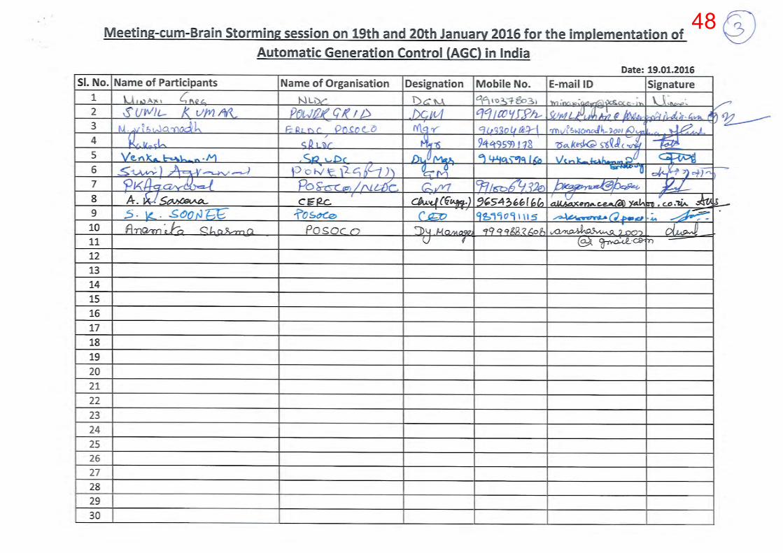
4. POSOCO had organized a two day discussion-cum-brainstorming session on implementation of
AGC in Indian power system at New Delhi on 19th and 20th January 2016. Representatives from
CERe, CEA, POWERGRID, NTPC and POSOCO participated in the above meeting. Professor
Anjan Bose, Professor, Washington State University, USA was also available as an expert during
this workshop. Four SCADA vendors were also invited to demonstrate the functionality of their
AGC software; three vendors presented the details of their software.
5. As a broad area of convergence after the two day session, a pilot project in each region was
agreed to be initiated to cover coal fired, gas based stations and storage hydro power stations. ft
was also discussed and agreed that generic technical specification should also be finalized under
13
4
the proposed pilot project. Accordingly, summary of the discussion-cum-brainstorming meeting,
along with the short term action points were communicated to CERC vide letter dated 15th March
2016. The copy of the same is enclosed as Anncxe-4.
6. The summary of the discussion-cum-brainstorming session had also been communicated to the
members of the Forum of Load Despatchers (FOLD) in its 16th meeting held on 2nd March 2016.
This was welcomed by the FOLD members.
7. From the interactions with national and international expelts on power systems and experience
with Ancillary Services till date, the general understanding of POSOCO is that different
solutions as a package like load and Renewable Energy (RE) generation forecast, proper
portfolio management by the states, primary response from the generators, secondary control in
the form of AGC, Ancillary Service products in different time frames etc. are needed for the
stable frequency operation orthe powcr system. No unique solution exists. A bad or no forccast
of loadlRE generation and poor portfolio management by the state utilities would lead to heavy
deviations from schedule and grid indiscipline exhausting all reserves in the system and making
the system insecure. Automatic Generation Control (AGC) effectiveness would have to be seen
in this overall context. AGC Pilot Project is one of the steps in that direction for stable frequency
operation and security of the grid. Since this pilot project is being implemented onjust two units
with very little spinning reserve to start with, the pilot AGC may not exert any control on the ISO
GW large Indian power system. However, the response of the generator for variation in Area
Control Error (ACE) due to deviations in tie line flows ofNOithern Region (NR) and frequency
can be seen in this pilot project. Valuable experience can be gained in terms of implementation
aspects, communication protocols, generator regulation and load following capabilities, cyber
security etc. which will be useful during implementation of secondary control on a large scale.
8. During the discussion with NTPC representatives in the above said meeting, NTPC Dadri stage
II was suggested by them for implementation of the first AGC pilot project keeping in view the
following:
a. Dadri Stage II power plant is located near NLDC, New Delhi.
b. Ease in monitoring the field level implementation process.
c. The variable cost of the power plant is higher than other thermal plants in Northern Region
under RLDC jurisdiction, being a load centre plant. Hence it is easy to keep Spinning
Reserves in the same. The only thermal plants in NR costlier than Dadri Stg -II are Dadri
Stg-I and Jhajjar. Other costlier plants (other than thennal) are all Gas based stations, which
might be considered for reserves subsequently.
14
5
9. Accordingly, a team from POSOCO, POWERGRID and Mis Siemens visited NTPC Dadri on 6th
May 2016 to explore the ground level requirements/issues (if any) in the implementation of
Automatic Generation Control (AGC) at NTPC Dadri as a pilot project. Representatives from
NTPC demonstrated the existing plant level control system and also discussed the requirements
at plant level.
10. The proposed AGC pilot project shall be operated from NLDC/RLDC along with the required
hardware and software to be installed at NLDC/RLDC and NTPC Dadri Stage II. From the
experience of the brainstorming meetings, plant visit and internal discussions, detailed technical
specifications of the pilot AGC project were prepared by POSOCO. The AGC software would be
integrated with the existing SCADA system at NLDC/RLDC and data exchange would take
place accordingly. Modelled generating station/units with the static and dynamic data wil! be
configured along with the desired real-time data in the proposed AGC software. Phasor
Measurement Units (PMUs) would be installed by NTPC separately on the generator terminals at
Dadri Stage-II for monitoring the generator behaviour during different contingencies in the
system.
11. Further, in discussions with NTPC it was decided 10 place a combined award [rom POSOCO's
side for works at both NLDC and NTPC Dadri end. NTPC would reimburse posoca the costs
for its portion. Based on this finalised scope of works, bids were invited from prospective
vendors in October 2016 and MIS Siemens emerged as the successful bidder. Letter of Award
(LOA) was issued to MIS Siemens on 181ft January 2017 to start the execution of the AGC pilot
project. Same is enclosed as Annexe-S. POSOCO would be separately approaching the
Commission for approval orthe expenditure incurred for the AGC pilot project.
12. The AGC Pilot project was also discussed in the meetings by WRPC and SRPC forums attended
by POSOCO. AGe Pilot Project was discussed with SRPC constituents during a workshop on
AGC dated 3rd October 2016 at SRLDC, Bangalore. A presentation was made by NLDC at
SRPC Board Meeting dated 24th _25th February 2017 on the topic of AGC. WRPC and posoca discussed the AGC Pilot project as an agenda item in the 2~day workshop from 9th ~l alh February
2017 at Mumbai.
13. A detailed half year analysis and feedback on Reserve Regulation Ancillary Services (RRAS)
implementation in Indian Grid covering implementation aspects, challenges was submitted for
perusal of the Hon'ble Commission on 17ill November 2016. A copy of this report is available on
POSOCQ's website also at https:l/posoco.in/do\Vnload/halr-year~fecdbaek-to~
ecrel?\','Pdmdl=8916. It was observed that for Regulation 'Down', about { 0.49 per unit has been
retained by RRAS provider on an average in the period of six months. While for Regulation 'up'
15
6

50 paise/kWh is being paid to the RRAS provider as per the Orders of the I-Ion 'ble Commission.
This aspect becomes important while finalizing the settlement mechanism for plants under AGC
outlined in the subsequent paragraphs.
14. The AGC Pilot Project mentioned is expected to be commissioned by mid-May 2017. While
severa! methods exist worldwide for compensating generating stations providing secondary
regulation services through AGC such as payments in tenns of Rs.JMW (considering opportunity
costs), a simple method is required considering that the power plant is under CERC'sjurisdiction
as far as tariff is concemed, its fixed cost liability is being shared by the beneficiaries and little
opportunity cost is involved in bringing this plant under AGC. To ensure the accounting and
settlement of the energy and power under Automatic Generation Control (AGC) and continuous
operation of the project the following is proposed
I. Energy produced due to AGC signals should be duly factored while working out the
deviations from the schedule.
ll. Aggregated AGC incrementa! MW signals over 15 minutes / 5 minutes would be logged in
MWh at NLDCINRLDC and NTPC Dadri as AGC MWh. NTPC Dadri may send its AGC
MWh account every week to NRLDCINLDC.
Ill. AGC MWh logs would be forwarded to NRPC secretariat on weekly basis to NRPC through
NRWC.
IV. Deviation in MWh for every 15~minute time block would be worked out as
MWh deviation = (Actual MWh)~(Scheduled MWh)~(AGC MWh) which would be settled as
per the existing Deviation Settlement Mechanism (DSM) Regulations.
v. For AGC MWh increase computed during every 15~minute time block, payment shall be
made based on variablc charges submitted to the NRPC by Dadri under RRAS Regulations.
Payment would be made from the Northern Region DSM pool.
VI. For AGe MWh reduction computed during a IS-minute time block, Dadri shall pay as per
the same variable charges above to the NR DSM pool.
vii. For AGC MWh computed for each 5~minute time block, 50 paise/kWh mark-up shaH be
payable to NTPC Dadri from NR DSM pool for both positive AGe MWh generation and
negative AGe MWh reduction.
Vill. It is proposed to keep 50-lOa MW Spinning Reserve at NTPC Dadri Stg~1I units 5&6
combined to start with. Hon'ble Commission may facilitate NRLDCINRPC to earmark 50
16
7
MW up/down reserves at NTPC Dadri Stage~n on days when full generation is requisitioned
or schedule is at technical minimum.
15. A presentation was made by POSOCO on loth March 2017 before the I-Ion'ble Commission on
the, frequency profile of India, operationalization of the CERC reserves order dated 13 th Oct
2015 and related aspects of AGC Pilot Project mentioned in above paragraphs. A copy of this
presentation is enclosed at Annexe-6.
16. A discussion on the proposed payment mechanism and related aspects of AGC Pilot Project was
held with NTPC at NLDC on 17th March 2017. A general consensus was arrived at after the
discussion on the items in the para 14.
Prayer:
Implementation of Automatic Generation Control (AGe) is a landmark event as far as power system
operation in India is concerned. The pilot project is the first step in this direction and all the
intricacies involved in generator's participation in regulation services would be experienced for the
first time.
The Hon'ble Commission may kindly approve
i. Commissioning of AGC Pilot Project between NLDC and NTPC Dadri Stage-II as mentioned in
above paragraphs.
ii. The procedure for accounting & settlement of the payments in respect of AGC services outlined
in para 14 above.
III. Similar pilot projects to be taken up by POSOCO, in at least one other regional grid of the
country.
iv. Issue of necessary directions for extending optical fibre connectivity to maximum number of
power plants under the control area jurisdiction of RLDCs so that technical feasibility for
pru1icipation of more generating stations under AGC is created.
v. Pass any other orders as this Hon'ble Commission may deem fit and proper under the facls and
circumstances of the present case and in the interest of Justice.
Date: 31 st March 2017
Place: New Delhi
17
8

9

Order in Suo-Motu Petition No. 11/SM/2015 Page 1 of 13
CENTRAL ELECTRICITY REGULATORY COMMISSION NEW DELHI
Petition No. 11/SM/2015
Coram: Shri Gireesh B. Pradhan, Chairperson Shri A.K. Singhal, Member Shri A.S. Bakshi, Member Dr. M.K. Iyer, Member
Date of Order: 13.10.2015
In the matter of Roadmap to operationalise Reserves in the country
ORDER
The Electricity Act, 2003 entrusts on the Central Commission important
responsibilities inter-alia of regulating the inter-State transmission of electricity,
specifying grid code and also enforcing standards with respect to quality, continuity and
reliability of service by licensees. Laying down of framework for effective and secure
grid operation is thus one of the most important mandates of the Commission. The
Central Commission has taken initiatives towards this end through regulations on Indian
Electricity Grid Code and Deviation Settlement Mechanism and related matters. The
Commission has also issued direction from time to time for enforcing grid discipline.
2. Over the period, reliance of the utilities on the grid for meeting their short term
energy demand was increasing. This caused serious threat to grid security. The
Commission, therefore, tightened the operating band of grid frequency and made
deviation charges stringent enough to discourage the utilities from deviation from their
schedule. This has started yielding the desired results in terms of operation of the grid
10

Order in Suo-Motu Petition No. 11/SM/2015 Page 2 of 13
closer to 50 Hz. The Commission has reiterated time and again that un-scheduled
inter-change (UI) mechanism cannot be used as platform for meeting the energy
demand of the utilities. Last mile imbalances are inevitable, but for this reliance on grid
is not desirable. This need be planned for, and adequate reserves need be contracted
to address such last mile imbalances.
3. The National Electricity Policy (NEP) mandates that adequate reserves may be
maintained to ensure secure grid operation:
“5.2.3 In order to fully meet both energy and peak demand by 2012, there is a need to create adequate reserve capacity margin. In addition to enhancing the overall availability of installed capacity to 85%, a spinning reserve of at least 5%, at national level, would need to be created to ensure grid security and quality and reliability of power supply.”
4. However, creation of adequate system reserve margin and spinning reserves at
national level has not yet materialised. In furtherance to the provisions relating to the
requirement of Spinning Reserves in the Electricity Act, 2003, National Electricity Policy
and Tariff Policy, and to facilitate-large scale integration of renewable energy sources,
balancing, deviation settlement mechanism and associated issues, CERC constituted a
Committee vide letter No, 25/1/2015/Reg. Aff. (SR)/CT.RC dated 29th May 2015, under
the chairmanship of Shri A.S. Bakshi, Member CERC, to examine the technical and
commercial issues in connection with Spinning Reserves and evolve suggested
regulatory interventions in this context.
5. The Committee submitted its final report to the Commission on 17th September
2015 (annexed as Annexure-I). Major findings of the Committee are as under:
11
Order in Suo-Motu Petition No. 11/SM/2015 Page 3 of 13
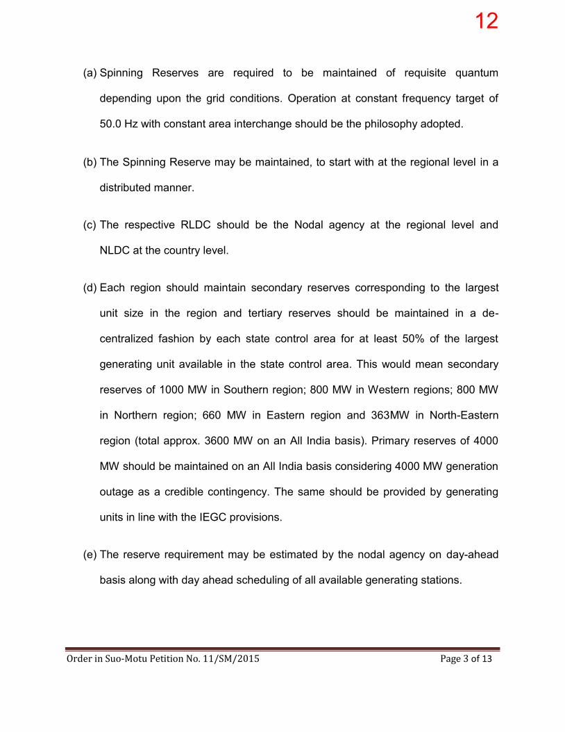
(a) Spinning Reserves are required to be maintained of requisite quantum
depending upon the grid conditions. Operation at constant frequency target of
50.0 Hz with constant area interchange should be the philosophy adopted.
(b) The Spinning Reserve may be maintained, to start with at the regional level in a
distributed manner.
(c) The respective RLDC should be the Nodal agency at the regional level and
NLDC at the country level.
(d) Each region should maintain secondary reserves corresponding to the largest
unit size in the region and tertiary reserves should be maintained in a de-
centralized fashion by each state control area for at least 50% of the largest
generating unit available in the state control area. This would mean secondary
reserves of 1000 MW in Southern region; 800 MW in Western regions; 800 MW
in Northern region; 660 MW in Eastern region and 363MW in North-Eastern
region (total approx. 3600 MW on an All India basis). Primary reserves of 4000
MW should be maintained on an All India basis considering 4000 MW generation
outage as a credible contingency. The same should be provided by generating
units in line with the IEGC provisions.
(e) The reserve requirement may be estimated by the nodal agency on day-ahead
basis along with day ahead scheduling of all available generating stations.
12
Order in Suo-Motu Petition No. 11/SM/2015 Page 4 of 13
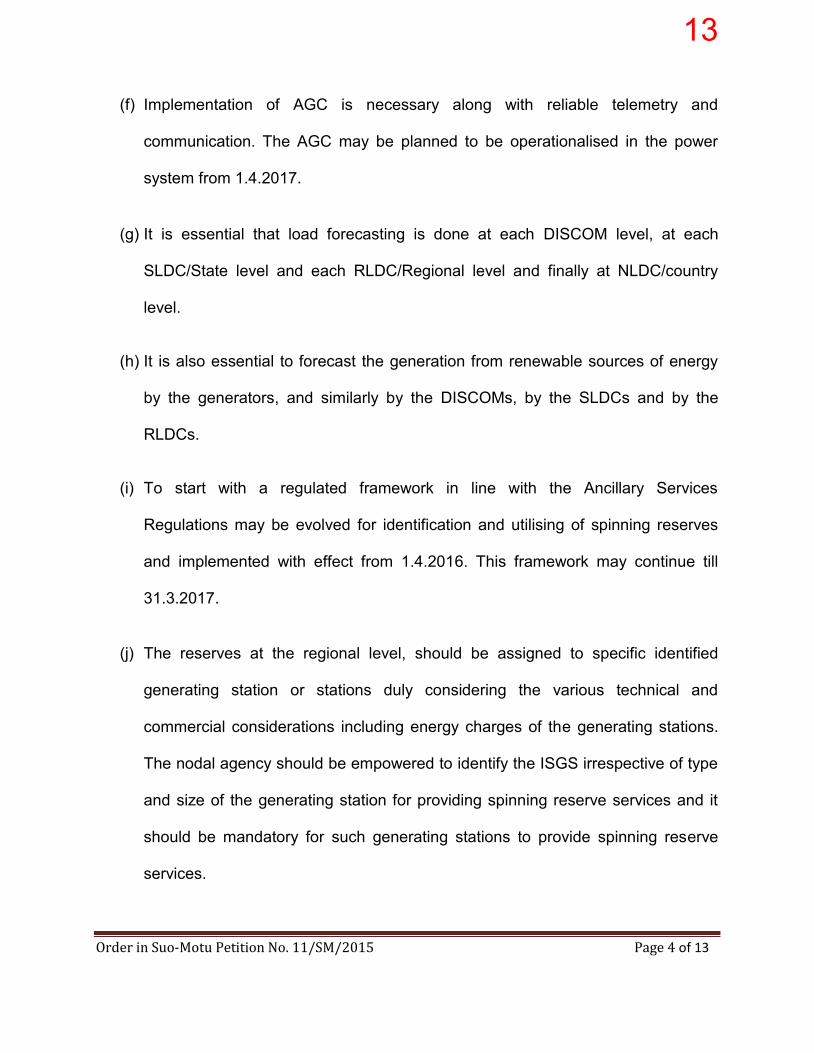
(f) Implementation of AGC is necessary along with reliable telemetry and
communication. The AGC may be planned to be operationalised in the power
system from 1.4.2017.
(g) It is essential that load forecasting is done at each DISCOM level, at each
SLDC/State level and each RLDC/Regional level and finally at NLDC/country
level.
(h) It is also essential to forecast the generation from renewable sources of energy
by the generators, and similarly by the DISCOMs, by the SLDCs and by the
RLDCs.
(i) To start with a regulated framework in line with the Ancillary Services
Regulations may be evolved for identification and utilising of spinning reserves
and implemented with effect from 1.4.2016. This framework may continue till
31.3.2017.
(j) The reserves at the regional level, should be assigned to specific identified
generating station or stations duly considering the various technical and
commercial considerations including energy charges of the generating stations.
The nodal agency should be empowered to identify the ISGS irrespective of type
and size of the generating station for providing spinning reserve services and it
should be mandatory for such generating stations to provide spinning reserve
services.
13
Order in Suo-Motu Petition No. 11/SM/2015 Page 5 of 13
(k) The nodal agency may have the option of carrying such reserves on one or more
plants on technical and commercial considerations and may withhold a part of
declared capacity on such plants from scheduling. It could be in terms of % of
declared capacity or in MW term as deemed fit.
(l) A framework as specified in the Central Electricity Regulatory Commission
(Ancillary Services Operations) Regulations, 2015 may be followed for the
Spinning Reserve Services as well. The Central Electricity Regulatory
Commission (Ancillary Services Operations) Regulations, 2015 may be amended
to incorporate the necessary changes in this regard.
(m)Going forward, a market based framework may be put in place from 1st April
2017 for achieving greater economy and efficiency in the system. A detailed
study is required to be carried out before the market mechanism on spinning
reserves is put in place. It is suggested that the NLDC be directed to commission
study through a consultant in the context and submit a proposal to the
Commission for approval.
The Commission has carefully considered and accepted the findings of the
Committee.
6. One of the important components of ensuring grid reliability includes achieving
adequacy of supply and maintaining the load-generation balance. This poses a
challenge to grid operators on various time-scales: on a daily level as weather varies,
for example, on an hourly level as load varies during the day, and on sub-hourly/time-
14

Order in Suo-Motu Petition No. 11/SM/2015 Page 6 of 13
block level as there are errors in forecasting of load or unplanned outages of generating
units or transmission lines. Sudden disturbances in the Power System can initiate a
steep fall or rise in the frequency of the Power System, which can be detrimental to the
Power System operation, if not contained immediately. Thus, to ensure 24x7 power
supply and grid reliability, grid operators must have access to reserves at different
locations and factoring transmission constraints, the system operators should be able to
increase or decrease power supply on the grid at any time of the day.
7. Three types of reserves are generally considered depending on the timeline of
initiation and functional need. Primary control refers to local automatic control available
in all conventional generators, which delivers reserve power negatively proportional to
frequency change. Such immediate automatic control is implemented through turbine
speed governors, in which the generating units respond quickly to the frequency
deviation as per droop characteristic of the units. However, this response to arrest
frequency drop or rise lasts for short period of up to 30 seconds - 15 minutes, within
which secondary control should come into play should the contingency last longer than
that. IEGC section 5.2(i) specifies a provision for primary reserves, as under:
“The recommended rate for changing the governor setting, i.e., supplementary control for increasing or decreasing the output (generation level) for all generating units, irrespective of their type and size, would be one (1.0) per cent per minute or as per manufacturer‟s limits. However, if frequency falls below 49.7Hz, all partly loaded generating units shall pick up additional load at a faster rate, according to their capability.”
However, this has not been adhered to fully by the generators.
15

Order in Suo-Motu Petition No. 11/SM/2015 Page 7 of 13
8. Secondary control involves Automatic Generation Control (AGC) which delivers
reserve power in order to bring back the frequency and the area interchange programs
to their target values. For AGC, units as well as load dispatch centres have to be
equipped with necessary communication infrastructure, as it involves sending
automated control signals from the LDC to the generator based on grid conditions. AGC
has been absent in the Indian power system. Very commonly, this results in „load
shedding‟ by DISCOMs in case generation is lagging load. The Indian power sector was
beset with scarcity for a long time; however, now the scenario is changing and margin
for reserves is feasible. With a large interconnected grid meeting a peak load of over
145 GW, both primary and secondary controls are essential components for reliable grid
operation.
9. Tertiary control refers to manual change in the dispatching and unit commitment
in order to restore the secondary control reserve, as loss of generator may cause a
system contingency that lasts for several hours.
10. Traditionally, imbalance handling on the Indian grid has been done through the
Unscheduled Interchange (UI) or the Deviation Settlement Mechanism (DSM)
framework, in which the frequency-linked UI rate gave a signal to the grid participants to
correct for instantaneous frequency deviations. However, it led to use not meant for,
and further grid indiscipline besides stress/constraints in the transmission network.
While measures like tightening of the operating grid frequency band and provision for
deterrent deviation charges, have been resorted to and this has resulted in
improvement of grid operation, the Commission feels that the power system operation in
16
Order in Suo-Motu Petition No. 11/SM/2015 Page 8 of 13
the country still needs to mature further. Even now States have been deviating from
schedule substantially. For instance, in 2014-15, Rajasthan deviated in the range of (+)
1202 to (-) 1324; UP in the range of 1613 to (-) 2291; Karnataka in the range of 945 to
(-) 787 etc.; Tamil Nadu in the range of 546 to (-) 990; Gujarat in the range of 1174 to
(-) 1162. These are not only undesirable but also a cause of serious concern. The DSM
Regulations provide for a periodic review of the DSM rates and the Commission directs
the Staff to undertake a review of the same and submit a proposal for consideration of
the Commission.
11. The Commission would like to underscore that grid does not generate electricity
and as such cannot be relied upon for meeting energy needs. Reserves and reserves
alone can address this and the earlier the stakeholders realise this, the better it is for
safe and secure system operation. Reserves assume greater significance additionally in
the wake of the goal of integration of large scale variable renewable energy sources.
With increasing penetration of variable and intermittent RE generation, flexible
generation such as pumped storage hydro plants are needed. There is a need for more
flexibility in the operation of conventional generation plants also and flexibility needs to
be quantified, measured and duly compensated for. The Commission has already made
a beginning in this direction by proposing amendment to the Indian Electricity Grid Code
(IEGC) in respect of „technical minimum‟ which is expected to be notified shortly. „Ramp
up‟ and „ramp down‟ rates are other important parameters for flexibility which would
gradually be introduced through Regulations.
17
Order in Suo-Motu Petition No. 11/SM/2015 Page 9 of 13
12. The grid operator would now be required to undertake planning exercise to meet
Net Load, which is defined as: Net load = Load – RE power. This quantum must be met
with conventional generation with adequate flexibility at every point in time. To even
begin an exercise of planning for ongoing load-generation balance, load forecasting is
essential. It is also necessary to ensure conventional generators to generate as per the
schedules. Forecasting and scheduling of solar and wind generating stations is the next
critical step for the grid operators to estimate the amount of RE power they can
anticipate to be injected into the grid, on a day-ahead and hour-ahead basis. Thus, the
variability that can be predicted in the forecasts must be accounted for in planning
flexible generation as well as tertiary reserves day-ahead and hour-ahead. Furthermore,
balancing the uncertainty of RE power on a continuous basis necessitates a streamlined
process for deploying spinning reserves. This would be effectively balancing the
forecasting error in net load.
13. The Commission notified Central Electricity Regulatory Commission (Ancillary
Services Operations) Regulations, 2015 on 19th August 2015 with the objective of
utilizing un-requisitioned surplus in ISGS. These regulations are a first step towards the
entire gamut of Ancillary Services, starting with tertiary frequency control services.
Applicable to regional entities, the regulations outline a framework for both Regulation
Up and Regulation Down service by Reserves Regulation Ancillary Services (RRAS)
providers. NLDC along with RLDC, operating as the nodal agency, shall call for these
services in varying situations, such as extreme weather events, loss of generating unit
18
Order in Suo-Motu Petition No. 11/SM/2015 Page 10 of 13
or transmission line outage, load-generation imbalance, etc. The RRAS providers shall
be paid from the Regional DSM Pools.
14. Furthermore, the Commission notified the Order on Extended Market Session on
Power Exchanges on 8th April, 2015, and the power exchanges started operating
extended hours for intra-day products by end of July. The trading window is now open
round-the-clock for delivery of power on the same day, with a 3-hour delivery time-
frame. This can enable to significantly correct for intra-day imbalances in a proactive
manner, and not passively rely on the grid for the same. It is expected that the
Distribution Control Centres (DCCs) of DISCOMs also operate in a 24 x 7 manner to
reap the advantages from these extended market sessions. Depending on the market
needs, there is a need for newer products in the electricity market to provide more
opportunities to the participants to balance their portfolio. The Commission directs the
staff to examine this aspect of market design and submit a proposal for consideration of
the Commission.
15. It is also expected that with provision for reserves and harnessing the same
through „controls‟, the inter area power flows would be manageable and help in
optimizing the Transmission Reliability Margin (TRM). This would benefit all
stakeholders to a great extent.
16. In due recognition of the above factors, the Commission would like to chart out a
road map for introduction of reserves in the country. Accordingly, the Commission
directs as under:
19

Order in Suo-Motu Petition No. 11/SM/2015 Page 11 of 13
(a) For reliable and secure grid operation, to maintain continuous load-generation
balance, to counter generation outages as well as unexpected load surges or
crashes, and for large scale integration of variable renewable power, it is
essential for the grid operators to have access to distributed Spinning Reserves
which are dispatched taking due care of transmission constraints whenever
required.
(b) The Commission reiterates the need for mandating Primary Reserves as well as
Automatic Generation Control (AGC) for enabling Secondary Reserves.
(i) All generating stations that are regional entities must plan to
operationalise AGC along with reliable telemetry and
communication by 1st April, 2017. This would entail a one-time
expense for the generators to install requisite software and
firmware, which could be compensated for. Communication
infrastructure must be planned by the CTU and developed in
parallel, in a cost-effective manner.
(ii) On the other hand, National/Regional/State Load Dispatch Centres
(NLDC/RLDCs/SLDCs) would need technical upgrades as well as
operational procedures to be able to send automated signals to
these generators. NLDC /RLDCs and SLDCs should plan to be
ready with requisite software and procedures by the same date.
20
Order in Suo-Motu Petition No. 11/SM/2015 Page 12 of 13
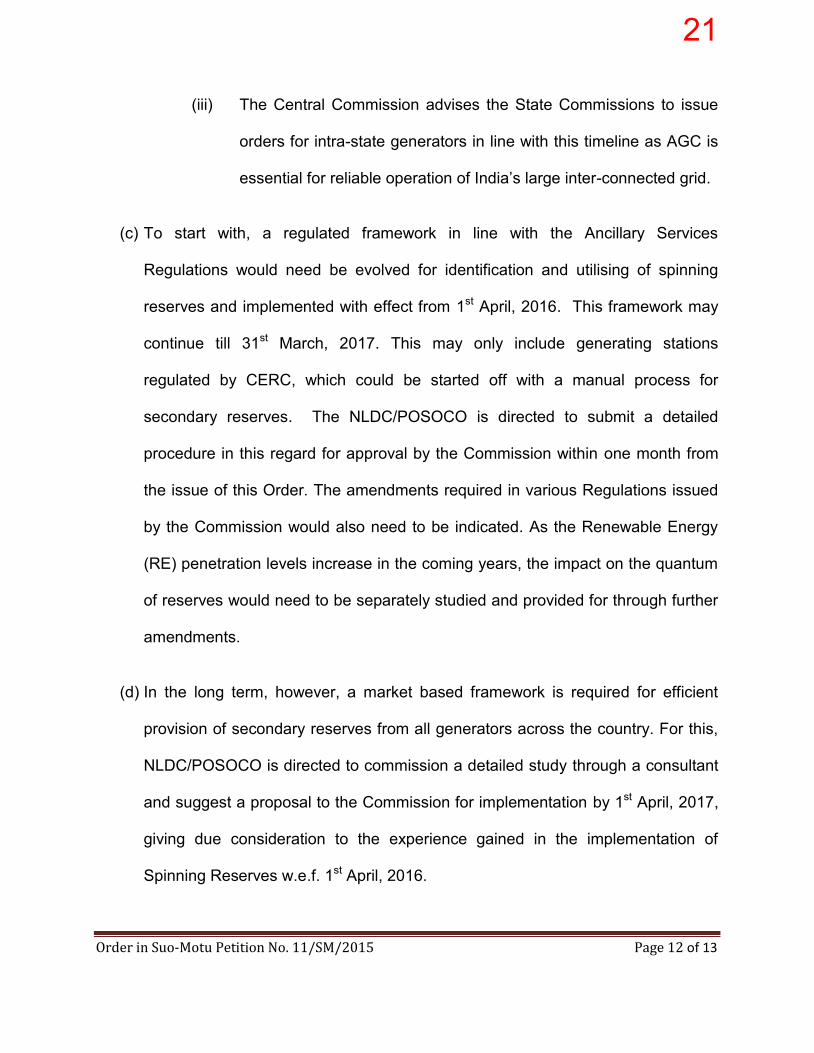
(iii) The Central Commission advises the State Commissions to issue
orders for intra-state generators in line with this timeline as AGC is
essential for reliable operation of India‟s large inter-connected grid.
(c) To start with, a regulated framework in line with the Ancillary Services
Regulations would need be evolved for identification and utilising of spinning
reserves and implemented with effect from 1st April, 2016. This framework may
continue till 31st March, 2017. This may only include generating stations
regulated by CERC, which could be started off with a manual process for
secondary reserves. The NLDC/POSOCO is directed to submit a detailed
procedure in this regard for approval by the Commission within one month from
the issue of this Order. The amendments required in various Regulations issued
by the Commission would also need to be indicated. As the Renewable Energy
(RE) penetration levels increase in the coming years, the impact on the quantum
of reserves would need to be separately studied and provided for through further
amendments.
(d) In the long term, however, a market based framework is required for efficient
provision of secondary reserves from all generators across the country. For this,
NLDC/POSOCO is directed to commission a detailed study through a consultant
and suggest a proposal to the Commission for implementation by 1st April, 2017,
giving due consideration to the experience gained in the implementation of
Spinning Reserves w.e.f. 1st April, 2016.
21

Order in Suo-Motu Petition No. 11/SM/2015 Page 13 of 13
(e) The States must undertake separate scheduling and energy accounting of all
generating and load entities. Deployment of DSM framework shall greatly
prepare the State to differentiate between and attribute deviations caused due to
various entities involved. Recording of this data shall also give the State grid
operator much needed clarity on which entities are responsible for schedule
deviations, and to what extent.
(f) Load forecasting must be undertaken by all DISCOMs. Combined with DSM, it is
the foundation on which strong and reliable grid management can be built.
(g) In order to ensure reliable and secure operation of the grid, in addition to
compliance to standards and regulations, adequate defense mechanisms such
as Under Frequency Relays (UFRs), df/dt (rate of change of frequency), System
Protection Schemes (SPS), etc. must be put in place and which also need to be
periodically reviewed and checked for healthiness.
17. The petition is disposed of in terms of the above directions.
sd/- sd/- sd/- sd/-
(Dr. M.K. Iyer) (A. S. Bakshi) (A.K. Singhal) (Gireesh B. Pradhan) Member Member Member Chairperson
22

23

(A wholly owned subsidiary of POWERGRID)
~ ~ ~ Cfil4f(14: aft-9, ~~ ffil, ~ ~~R'("'" ~~ CficCllf{41 mr:r, ~ ~-110 016 Registered & Corporate Office : B - 9, 1st Floor, Qutub Institutional Area, Katwaria Sarai, New Delhi - 110 016 Website : www.posoco.in, www.nldc.in, Tel: 011-26536832, 26524522, Fax: 011-26524525, 26536901
~~ tr: POSOCO/Legai/NLDC R1 i Cfl: 15.12.2015
Subject: Roadmap to operationalise Reserves in the country and procedure- regarding
Madam,
The Hon'ble Commission has vide its Order dated 13th October 2015 in petition no
11/SM/2015 paved a way forward for operationalizing generation reserves in the country.
The Hon'ble Commission directed NLDC/POSOCO to submit a detailed procedure in this
regard for approval by the Commission. In this connection, an outline of the same is
enclosed. Considering the complexity of the issue and the fact that shortly the Ancillary
Services Framework would become operational when directed by the Commission, further
discussions would be required with the stakeholders, particularly the generators identified
for secondary control. We may be kindly permitted to submit a detailed draft procedure to
operationalize Reserves in the country three {3) months after implementation of the CERC
(Ancillary Services) Regulations, 2015.
~.
ct\k\1,~'~'~ ( ~. eft. ~· ~)
Cfli441Wfl ~~fCfl. u. m. ~. ~.
~ ~<1 l!cf :CI~~<1 lf ~ ~ Save Energy for Benefit of Self and Nation
24

Power System Operation Corporation Limited
New Delhi
15th Dec 2015
Sub: Operationalization of generation reserves in the country
1.0 The Hon’ble Commission has vide order dated 13th Oct 2015 in petition no
11/SM/2015 given a roadmap for operationalization of reserves in the country. The
order was based on the Report of the Committee constituted earlier by CERC under
the Chairmanship of Shri A S Bakshi, Hon’ble Member, CERC.
2.0 As per the recommendations of the Committee constituted by CERC to examine the
technical and commercial issues in connection with Spinning Reserves, each region
should maintain secondary reserves corresponding to the largest unit size in the
region and tertiary reserves should be maintained in a decentralized fashion by each
state control area for at least 50% of the largest generating unit available in the state
control area. This would mean secondary reserves of 1000 MW in Southern region;
800 MW in Western region; 800 MW in Northern region; 660 MW in Eastern region
and 363 MW in North-Eastern region (total approx. 3623 MW on an All India basis).
Primary reserves of 4000 MW should be maintained on an All India basis considering
4000 MW generation outage as a credible contingency.
3.0 Tentative plausible generators have been identified for providing the requisite
secondary reserve and the list is enclosed. It would be observed from these lists that
in case the stations with variable cost less than 250 paise/kWh have to be excluded
from secondary control, then limited power stations in each region are available and
almost 35-100% of this capacity has to be kept as reserve in some of the regions
which might be impractical. Primary Reserves have to be maintained by all the
generators mandated by IEGC and need not be separately identified. Tertiary
Reserves operationalization needs proactive sensitization of the states regarding the
CERC Road map to operationalize Reserves.
4.0 To evolve a procedure, some further brainstorming has to be done with all
concerned parties (particularly with the identified generating plants as
communication and control infrastructure is needed at the generator end also to
operationalize the secondary reserves). Also, from the philosophy and
implementation side a few questions have to be decided after discussion and
brainstorming (like the current meaning and usage of Un Requisitioned Surplus (URS)
after the CERC Ancillary Services Regulations, security constrained merit order, day
25
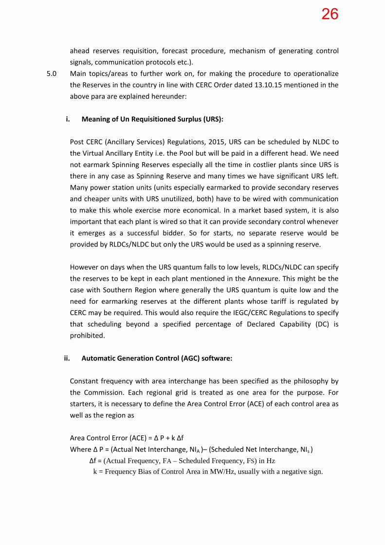
ahead reserves requisition, forecast procedure, mechanism of generating control
signals, communication protocols etc.).
5.0 Main topics/areas to further work on, for making the procedure to operationalize
the Reserves in the country in line with CERC Order dated 13.10.15 mentioned in the
above para are explained hereunder:
i. Meaning of Un Requisitioned Surplus (URS):
Post CERC (Ancillary Services) Regulations, 2015, URS can be scheduled by NLDC to
the Virtual Ancillary Entity i.e. the Pool but will be paid in a different head. We need
not earmark Spinning Reserves especially all the time in costlier plants since URS is
there in any case as Spinning Reserve and many times we have significant URS left.
Many power station units (units especially earmarked to provide secondary reserves
and cheaper units with URS unutilized, both) have to be wired with communication
to make this whole exercise more economical. In a market based system, it is also
important that each plant is wired so that it can provide secondary control whenever
it emerges as a successful bidder. So for starts, no separate reserve would be
provided by RLDCs/NLDC but only the URS would be used as a spinning reserve.
However on days when the URS quantum falls to low levels, RLDCs/NLDC can specify
the reserves to be kept in each plant mentioned in the Annexure. This might be the
case with Southern Region where generally the URS quantum is quite low and the
need for earmarking reserves at the different plants whose tariff is regulated by
CERC may be required. This would also require the IEGC/CERC Regulations to specify
that scheduling beyond a specified percentage of Declared Capability (DC) is
prohibited.
ii. Automatic Generation Control (AGC) software:
Constant frequency with area interchange has been specified as the philosophy by
the Commission. Each regional grid is treated as one area for the purpose. For
starters, it is necessary to define the Area Control Error (ACE) of each control area as
well as the region as
Area Control Error (ACE) = ∆ P + k ∆f
Where ∆ P = (Actual Net Interchange, NIA )– (Scheduled Net Interchange, NIs )
∆f = (Actual Frequency, FA – Scheduled Frequency, FS) in Hz
k = Frequency Bias of Control Area in MW/Hz, usually with a negative sign.
26

For starters, the value of ‘k’ could be taken based on the past trend of regional
Frequency Response Characteristics (FRC). Accurate values of ∆ P also necessitates
proper availability of real time data which is also a subject matter of 7/SM/2014
petition pending before the Commission.
The control centres of the five RLDCs have already been upgraded recently. As the
specifications for the same had been formulated around 2010-11, provision for AGC
was not kept at that stage. The NLDC Control Centre is yet to be upgraded and as of
now, POSOCO has kept a provision for AGC. Detailed implementation logic has to be
discussed with the prospective vendors. The software would obviously require
customization to adapt it to Indian Power System on account of URS. Worldwide,
AGC software running at one control centre would try to bring ACE of the particular
control area to zero. In the Indian context, the AGC software at NLDC would
essentially be the equivalent of 5 separate AGC softwares running at the same
control centre or AGC software with five separate regional models at NLDC.
AGC software at NLDC alone may be insufficient. The AGC signals transmitted to the
power plant would indicate the MW up or MW down for the plant as a whole.
Within the plant, suitable Programmable Logic Controllers (PLCs) would have to
distribute this MW on the different generating units. There would have to be close
coordination between the control centre AGC vendor and the plant vendor. In case
the control centre AGC software itself gives unit wise regulation, then the
implementation at plant level would also have to be studied from implementation
logistics. AGC software requirement at SLDCs needs to be further debated and
understood.
Considering the above complexities, POSOCO proposes to first take up a pilot project
with one of the NTPC plants in a region based on which further activities could be
taken up. In case the entire country were to be treated as one control area and
frequency control was the sole objective, a manual system could have been feasible
as was being done in the UK system. However, constant frequency with area
interchange control is difficult albeit impossible to achieve with manual control. Even
the NORDEL system has migrated to AGC (known as Load Frequency Control or
Frequency Restoration Service-Automatic).
27

iii. Communication:
One important requirement in this whole process is the communication. We would
need depending on the philosophy we would agree with later, reliable two way
communication from all/many power stations under RLDC’s jurisdiction, as it would
be one of the inputs and outputs to the AGC software. For automatic generation
control, the communication protocols and type of signals (continuous or step) have
to be discussed with all the major parties.
iv. Security Constrained Merit Order:
To make the process of dispatch of Reserves economic, as long as the flows don’t
exceed the ATC limit, All India merit order can be followed; else region wise merit
order has to be followed. With this strategy, region wise ACE becomes redundant
and the focus would be on only all India frequency restoration as long as flows don’t
exceed ATC. But, in classical theory, region wise ACE is used to make the secondary
control decision to counter the probabilistic unit tripping and to do the load
following.
Making the choice of philosophy is one important step and has to be frozen first.
v. Day ahead Reserves:
The Reserves have to be decided day ahead using the available demand forecast and
the requisition of the entities after the R0 revision is put in the website by respective
RLDCs. This might need some experience obtained after implementing the CERC
(Ancillary Services) Regulations, 2015.
vi. Commercial:
Two key issues arise; how would fixed charges be paid for the reserves kept in
different power plants and how would the variable charges be paid for the
regulation up/down services? A method to convert the AGC signals to a ‘schedule’ to
be superimposed over the normal schedule is required which would form the
baseline for accounting for deviations, under the Deviation Settlement Mechanism
(DSM) Regulations.
28

The Hon’ble Commission has introduced the CERC (Ancillary Services) Regulations, 2015 on
19.08.15. A comprehensive procedure has been drafted to this end by POSOCO and
submitted to the Hon’ble Commission recently on 2nd Nov 2015 for approval. The
implementation of the same shall augur a worthy and important experience for the
development of a suitable procedure for operationalizing reserves in the Indian market.
In light of the observations made above, a detailed procedure to operationalize Reserves in
the country shall be framed in consultation with the Hon’ble Commission and submitted
three (3) months after implementation of the CERC (Ancillary Services) Regulations, 2015.
x-----x------x
29

NR 800 All India 4000 MW
ER 660WR 800SR 1000
NER 363Total 3623
Region State Tertiary Reserves needed in State in MW
Largest Generator Size
Punjab 400 Talwandi Saboo 800Haryana 330 CLP Jhajjar(JV)/Khedar 660Rajasthan 330 Kawai 660Delhi 105 Badarpur/Bawana 210UP 330 Lalitpur 660Uttarakhand 38 Maneri 76HP 50 Baspa 100J&K 75 Baglihar 150Chandigarh 0 nil 0NR Total 1658 3316Chhattisgarh 250 Korba West 500Gujarat 330 Vadinar 660MP 300 Malwa 600Maharashtra 330 Tiroda 660Goa 0 nil 0DD 0 nil 0DNH 0 nil 0Essar steel 62.5 Essar 125WR Total 1353 2705Andhra Pradesh 400 SDSTPS 800Telangana 250 Kakatiya 500Karnataka 300 UPCL 600Kerala 62.5 Kayamkulam 125Tamil Nadu 300 Mettur 600Pondy 0 nil 0SR Total 1343 2685Bihar 55 MTPS 110DVC 300 Raghunathpur 600Jharkhand 105 Tenughat 210Odisha 300 Sterlite 600West Bengal 150 Sagardighi 300Sikkim 0 nil 0ER total 857 1713Arunachal Pradesh 0 nil 0Assam 25 Langpi 50Manipur 0 nil 0Meghalaya 22.5 MPL 45Mizoram 2 Kolasib 4Nagaland 4 Khiphire 8Tripura 11 Rokhia 22NER total 65 129
Total 5218 10435
UMPP Outage
Primary Reserves Quantum needed in MW
NER
Secondary Reserves Quantum needed in MW (Region wise)
Tertiary Reserves Quantum needed in MW (State Control Area Wise)
NR
WR
SR
ER
Summary of Reserves required as per the CERC order
30
S.No. Region Type Name UNITSTOTAL (MW)
Energy Charge Rs /
Kwh
For Gas Stations (Energy
charge of next costly
fuel)
Fixed Charge (Rs./kWh)
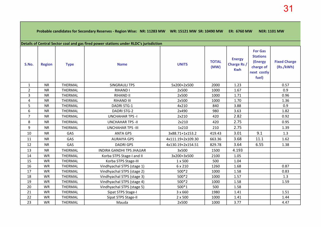
1 NR THERMAL SINGRAULI TPS 5x200+2x500 2000 1.23 0.572 NR THERMAL RIHAND I 2x500 1000 1.67 0.93 NR THERMAL RIHAND II 2x500 1000 1.71 0.964 NR THERMAL RIHAND III 2x500 1000 1.70 1.365 NR THERMAL DADRI STG-1 4x210 840 3.88 0.96 NR THERMAL DADRI STG-2 2x490 980 3.63 1.827 NR THERMAL UNCHAHAR TPS -I 2x210 420 2.82 0.928 NR THERMAL UNCHAHAR TPS -II 2x210 420 2.75 0.959 NR THERMAL UNCHAHAR TPS -III 1x210 210 2.75 1.39
10 NR GAS ANTA GPS 3x88.71+1x153.2 419.43 3.01 9.1 1.311 NR GAS AURAIYA GPS 4x111.19+2x109.30 663.36 3.68 11.1 1.6212 NR GAS DADRI GPS 4x130.19+2x154.51 829.78 3.64 6.55 1.3813 NR THERMAL INDIRA GANDHI TPS JHAJJAR 3x500 1500 4.19314 WR THERMAL Korba STPS Stage-I and II 3x200+3x500 2100 1.0515 WR THERMAL Korba STPS Stage-III 1 x 500 500 1.0416 WR THERMAL Vindhyachal STPS (stage 1) 6 x 210 1260 1.68 0.8717 WR THERMAL Vindhyachal STPS (stage 2) 500*2 1000 1.58 0.8318 WR THERMAL Vindhyachal STPS (stage 3) 500*2 1000 1.57 1.319 WR THERMAL Vindhyachal STPS (stage 4) 500*2 1000 1.58 1.5920 WR THERMAL Vindhyachal STPS (stage 5) 500*1 500 1.5821 WR THERMAL Sipat STPS Stage-I 3 x 660 1980 1.41 1.5122 WR THERMAL Sipat STPS Stage-II 2 x 500 1000 1.41 1.4423 WR THERMAL Mauda 2x500 1000 3.77 4.47
Probable candidates for Secondary Reserves - Region Wise: NR: 11283 MW WR: 15121 MW SR: 10490 MW ER: 6760 MW NER: 1101 MW
Details of Central Sector coal and gas fired power stations under RLDC's jurisdiction
31
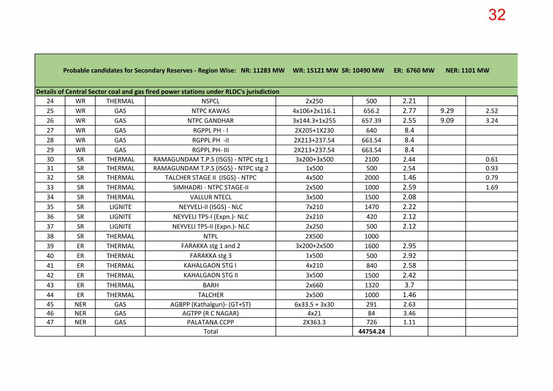
Probable candidates for Secondary Reserves - Region Wise: NR: 11283 MW WR: 15121 MW SR: 10490 MW ER: 6760 MW NER: 1101 MW
Details of Central Sector coal and gas fired power stations under RLDC's jurisdiction24 WR THERMAL NSPCL 2x250 500 2.2125 WR GAS NTPC KAWAS 4x10⁶+2x116.1 656.2 2.77 9.29 2.5226 WR GAS NTPC GANDHAR 3x144.3+1x255 657.39 2.55 9.09 3.2427 WR GAS RGPPL PH - I 2X205+1X230 640 8.428 WR GAS RGPPL PH -II 2X213+237.54 663.54 8.429 WR GAS RGPPL PH- III 2X213+237.54 663.54 8.430 SR THERMAL RAMAGUNDAM T.P.S (ISGS) - NTPC stg 1 3x200+3x500 2100 2.44 0.6131 SR THERMAL RAMAGUNDAM T.P.S (ISGS) - NTPC stg 2 1x500 500 2.54 0.9332 SR THERMAL TALCHER STAGE II (ISGS) - NTPC 4x500 2000 1.46 0.7933 SR THERMAL SIMHADRI - NTPC STAGE-II 2x500 1000 2.59 1.6934 SR THERMAL VALLUR NTECL 3x500 1500 2.0835 SR LIGNITE NEYVELI-II (ISGS) - NLC 7x210 1470 2.2236 SR LIGNITE NEYVELI TPS-I (Expn.)- NLC 2x210 420 2.1237 SR LIGNITE NEYVELI TPS-II (Expn.)- NLC 2x250 500 2.1238 SR THERMAL NTPL 2X500 100039 ER THERMAL FARAKKA stg 1 and 2 3x200+2x500 1600 2.9540 ER THERMAL FARAKKA stg 3 1x500 500 2.9241 ER THERMAL KAHALGAON STG I 4x210 840 2.5842 ER THERMAL KAHALGAON STG II 3x500 1500 2.4243 ER THERMAL BARH 2x660 1320 3.744 ER THERMAL TALCHER 2x500 1000 1.4645 NER GAS AGBPP (Kathalguri)- (GT+ST) 6x33.5 + 3x30 291 2.6346 NER GAS AGTPP (R C NAGAR) 4x21 84 3.4647 NER GAS PALATANA CCPP 2X363.3 726 1.11
Total 44754.24
32

S.No. Region Type Name UNITSTOTAL (MW)
Energy
Charge Rs
/ Kwh
For Gas Stations (Energy
charge of next costly
fuel)
1 WR THERMAL Mauda 2x500 1000 3.77Total Reserves Required in WR 800
2 WR GAS NTPC KAWAS4x106+2x1
16.1656.2
2.77 9.29
Total Capacity available in this price range 2313
3 WR GAS NTPC GANDHAR3x144.3+1
x255657.39 2.55 9.09 Percentage 35
4 SR THERMALSIMHADRI - NTPC STAGE-
II2x500 1000 2.59
5 SR THERMALRAMAGUNDAM T.P.S
(ISGS) - NTPC stg 21x500 500 2.54
Total Reserves Required in SR 1000
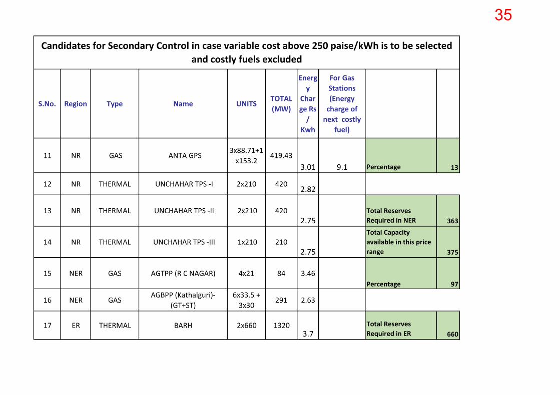
Candidates for Secondary Control in case variable cost above 250 paise/kWh is to be selected and costly fuels excluded
33

S.No. Region Type Name UNITSTOTAL (MW)
Energy
Charge Rs
/ Kwh
For Gas Stations (Energy
charge of next costly
fuel)
Candidates for Secondary Control in case variable cost above 250 paise/kWh is to be selected and costly fuels excluded
6 NR THERMALINDIRA GANDHI TPS
JHAJJAR3x500 1500 4.19 Total Capacity
available in this price range 1500
7 NR THERMAL DADRI STG-1 4x210 840 3.88Percentage 67
8 NR GAS AURAIYA GPS4x111.19+
2x109.3663.36
3.68 11.1
9 NR GAS DADRI GPS4x130.19+
2x154.5 829.78
3.64 6.55Total Reserves Required in NR 800
10 NR THERMAL DADRI STG-2 2x490 980 3.63 Total Capacity available in this price range 6282
34
S.No. Region Type Name UNITSTOTAL (MW)
Energy
Charge Rs
/ Kwh
For Gas Stations (Energy
charge of next costly
fuel)
Candidates for Secondary Control in case variable cost above 250 paise/kWh is to be selected and costly fuels excluded
11 NR GAS ANTA GPS3x88.71+1
x153.2 419.43
3.01 9.1 Percentage 13
12 NR THERMAL UNCHAHAR TPS -I 2x210 420 2.82
13 NR THERMAL UNCHAHAR TPS -II 2x210 4202.75
Total Reserves Required in NER 363
14 NR THERMAL UNCHAHAR TPS -III 1x210 2102.75
Total Capacity available in this price range 375
15 NER GAS AGTPP (R C NAGAR) 4x21 84 3.46Percentage 97
16 NER GASAGBPP (Kathalguri)-
(GT+ST)6x33.5 +
3x30291 2.63
17 ER THERMAL BARH 2x660 13203.7
Total Reserves Required in ER 660
35
S.No. Region Type Name UNITSTOTAL (MW)
Energy
Charge Rs
/ Kwh
For Gas Stations (Energy
charge of next costly
fuel)
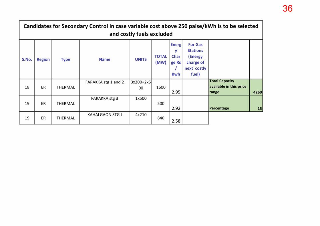
Candidates for Secondary Control in case variable cost above 250 paise/kWh is to be selected and costly fuels excluded
18 ER THERMALFARAKKA stg 1 and 2 3x200+2x5
00 16002.95
Total Capacity available in this price range 4260
19 ER THERMALFARAKKA stg 3 1x500
5002.92 Percentage 15
19 ER THERMALKAHALGAON STG I 4x210
840 2.58
36

37

CENTRAL ELECTRICITY REGULATORY COMMISSION
No.: 1110/20 12-Reg.Aff.(REC-Gen. )/CERC
Shri S.K. Soonee Chief Executive Officer Power System Operation Corporation (POSOCO) 18-A, Shaheed Jeet Singh Sansanwal Marg Katwaria Sarai New Delhi- 110 016.
artttftr~ CERC
Dated: 05111 February, 2016
Subject: Grant of extension to POSOCO for submission of implementation plan on Spinning Reserves
Sir,
This has reference to the Power System Operation Corporation Limited's letter No. POSOCO/Legal/NLDC 1139 dated 15.12.2015 requesting Central Electricity Regulatory Commission (CERC) for grant of extension to POSOCO for submission of implementation plan on Spinning Reserves. The matter has been examined in the Commission.
2. The Central Commission has issued a roadmap to operationalize Reserves in the country through Suo-Motu Petition No. 11/SM/2015 dated 13.10.2015. The objective of the order was to provide a vision to introduce Spinning Reserves in the country, which is one of the important components of ensuring grid reliability by achieving adequacy of supply and maintaining load-generation balance.
3. Considering the relevance of experience and learnings from Ancillary Services, the request received from POSOCO seeking grant of extension for submission on implementation plan on Spi1ming Reserves has been accepted by the competent authority.
4. POSOCO is advised to submit the draft detailed procedure and impiementation plan for Reserves within three months of impleme~on of
""" Ancillary Services Regulations.
Yours faithfully,
(Sushanta K~j;e) £1) -L'- i)-C. ~ ?/,Qf-JJ) "-Joint Chief(RA)
~ '\ {\ /, ;- 3={J\ ~ ~ ~) fi.rl' ~\ tft~il ~-fttcl. T.l~<ffi(f) ~fWll. 36. \JRlJ~. ~ ~~-110 oo1
Third Floor, Chanderlok Building, 36, Jan path, New Delhi-1·1 0 001 Phone: 91-11 -2335 3503 Fax: 91-11-2375 3923 E-mail: [email protected]
38

39

40

41

Page 1 of 4
Brainstorming session on 19th and 20th Jan 2016 at POSOCO, NLDC, New Delhi on
implementation of Automatic Generation Control (AGC)
1.0 Background:
A two day meeting cum brainstorming session was held on 19th and 20th Jan 2015 at NLDC,
New Delhi on the topic of implementation of Automatic Generation Control (AGC). Representatives
from NTPC Ltd., Central Electricity Regulatory Commission (CERC), Central Electricity Authority (CEA),
POWERGRID and POSOCO attended the meeting. Mr. P.P. Francis, ex-NTPC professional, also attended
the meeting on 19th Jan 2016 and gave valuable inputs. The list of participants is enclosed at Annexe-I.
Executives from ERLDC, WRLDC, NERLDC and SRLDC also participated through Video Conference (VC).
Professor Anjan Bose, Regents Professor, Washington State University presided over the two
day session. CEO, POSOCO, in his opening remarks, stated that all the discussions are required from
practical implementation point of view. The objective should be to have a prototype, learn from the
experience, gain confidence and make it gradually better.
Professor Anjan Bose stated that the most important thing to target at this time is to make
something work on the Indian grid that meets all the requirements for frequency control as laid out in
the rulings of the CERC. Such a prototype system doesn’t have to be comprehensive or the most
efficient; the key issue is to demonstrate that it works. It needs to be appreciated that the Indian grid is
a big and complex one and completely interconnected, so complete implementation of a smooth
running frequency control will take time and learning.
With these opening remarks, the presentations and discussion followed.
2.0 Presentations made in the two day meeting
POSOCO’s presentation covered the salient features of the 13th October 2015 order of CERC on spinning
reserves and the communication dated 15th Dec 2015 from POSOCO to CERC outlining the broad areas
of implementation which needed a broad agreement. A copy of POSOCO’s presentation is enclosed at
Annexe-II.
NTPC’s presentation covered on the need to keep higher variable cost generating stations on AGC,
availability of Coordinated Master Control (CMC) as a necessary requirement for placing units on AGC
and the associated higher O & M costs and Heat Rate degradation on account of flexing of generation
due to AGC actions. A copy of NTPC’s presentation is enclosed at Annexe-III.
POWERGRID Load Despatch & Communication (LD & C) division, who are consultants to POSOCO for the
SCADA/EMS upgradation project, presented the outline of specifications for AGC in the NLDC
upgradation project. The extracts from the specification presented by POWERGRID is enclosed at
42
Page 2 of 4
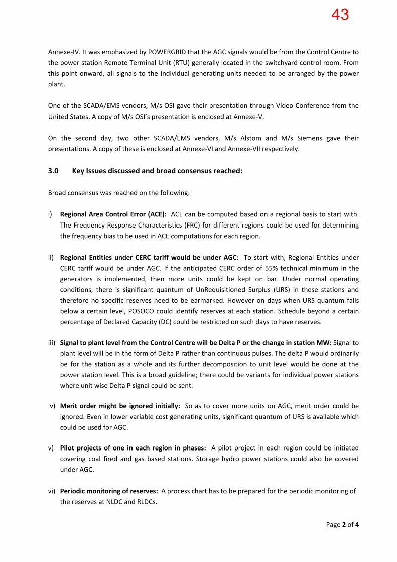
Annexe-IV. It was emphasized by POWERGRID that the AGC signals would be from the Control Centre to
the power station Remote Terminal Unit (RTU) generally located in the switchyard control room. From
this point onward, all signals to the individual generating units needed to be arranged by the power
plant.
One of the SCADA/EMS vendors, M/s OSI gave their presentation through Video Conference from the
United States. A copy of M/s OSI’s presentation is enclosed at Annexe-V.
On the second day, two other SCADA/EMS vendors, M/s Alstom and M/s Siemens gave their
presentations. A copy of these is enclosed at Annexe-VI and Annexe-VII respectively.
3.0 Key Issues discussed and broad consensus reached:
Broad consensus was reached on the following:
i) Regional Area Control Error (ACE): ACE can be computed based on a regional basis to start with.
The Frequency Response Characteristics (FRC) for different regions could be used for determining
the frequency bias to be used in ACE computations for each region.
ii) Regional Entities under CERC tariff would be under AGC: To start with, Regional Entities under
CERC tariff would be under AGC. If the anticipated CERC order of 55% technical minimum in the
generators is implemented, then more units could be kept on bar. Under normal operating
conditions, there is significant quantum of UnRequisitioned Surplus (URS) in these stations and
therefore no specific reserves need to be earmarked. However on days when URS quantum falls
below a certain level, POSOCO could identify reserves at each station. Schedule beyond a certain
percentage of Declared Capacity (DC) could be restricted on such days to have reserves.
iii) Signal to plant level from the Control Centre will be Delta P or the change in station MW: Signal to
plant level will be in the form of Delta P rather than continuous pulses. The delta P would ordinarily
be for the station as a whole and its further decomposition to unit level would be done at the
power station level. This is a broad guideline; there could be variants for individual power stations
where unit wise Delta P signal could be sent.
iv) Merit order might be ignored initially: So as to cover more units on AGC, merit order could be
ignored. Even in lower variable cost generating units, significant quantum of URS is available which
could be used for AGC.
v) Pilot projects of one in each region in phases: A pilot project in each region could be initiated
covering coal fired and gas based stations. Storage hydro power stations could also be covered
under AGC.
vi) Periodic monitoring of reserves: A process chart has to be prepared for the periodic monitoring of
the reserves at NLDC and RLDCs.
43
Page 3 of 4
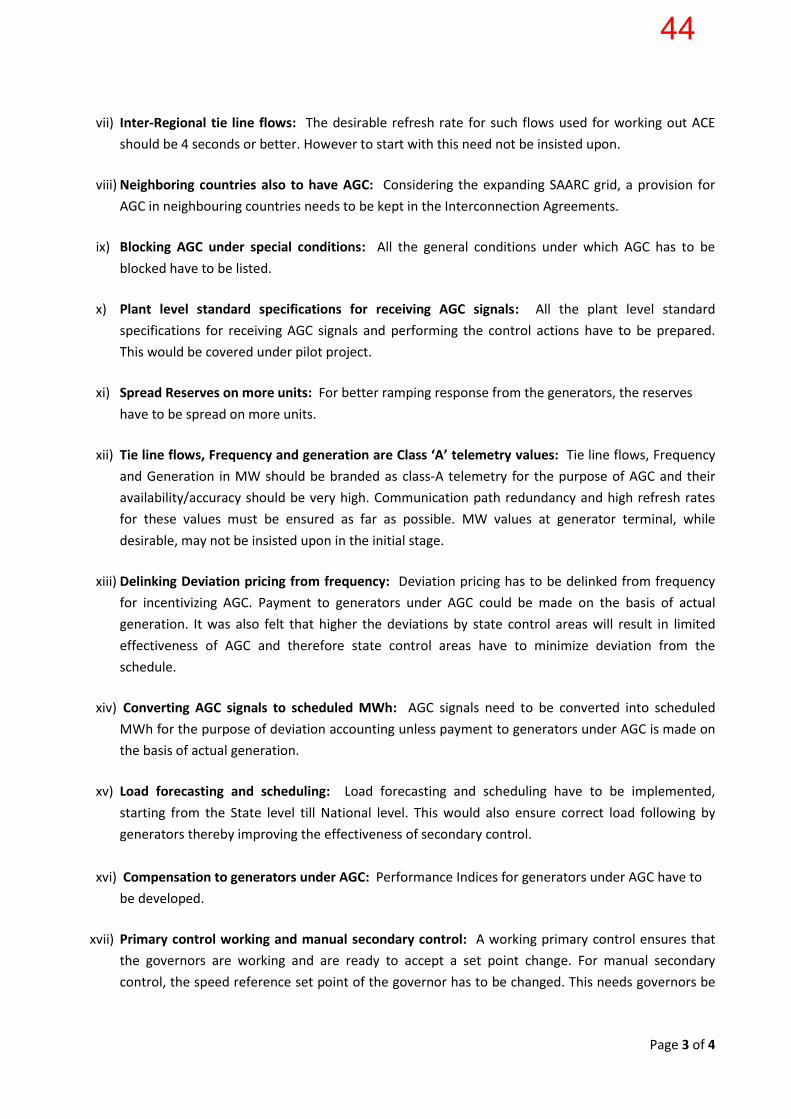
vii) Inter-Regional tie line flows: The desirable refresh rate for such flows used for working out ACE
should be 4 seconds or better. However to start with this need not be insisted upon.
viii) Neighboring countries also to have AGC: Considering the expanding SAARC grid, a provision for
AGC in neighbouring countries needs to be kept in the Interconnection Agreements.
ix) Blocking AGC under special conditions: All the general conditions under which AGC has to be
blocked have to be listed.
x) Plant level standard specifications for receiving AGC signals: All the plant level standard
specifications for receiving AGC signals and performing the control actions have to be prepared.
This would be covered under pilot project.
xi) Spread Reserves on more units: For better ramping response from the generators, the reserves
have to be spread on more units.
xii) Tie line flows, Frequency and generation are Class ‘A’ telemetry values: Tie line flows, Frequency
and Generation in MW should be branded as class-A telemetry for the purpose of AGC and their
availability/accuracy should be very high. Communication path redundancy and high refresh rates
for these values must be ensured as far as possible. MW values at generator terminal, while
desirable, may not be insisted upon in the initial stage.
xiii) Delinking Deviation pricing from frequency: Deviation pricing has to be delinked from frequency
for incentivizing AGC. Payment to generators under AGC could be made on the basis of actual
generation. It was also felt that higher the deviations by state control areas will result in limited
effectiveness of AGC and therefore state control areas have to minimize deviation from the
schedule.
xiv) Converting AGC signals to scheduled MWh: AGC signals need to be converted into scheduled
MWh for the purpose of deviation accounting unless payment to generators under AGC is made on
the basis of actual generation.
xv) Load forecasting and scheduling: Load forecasting and scheduling have to be implemented,
starting from the State level till National level. This would also ensure correct load following by
generators thereby improving the effectiveness of secondary control.
xvi) Compensation to generators under AGC: Performance Indices for generators under AGC have to
be developed.
xvii) Primary control working and manual secondary control: A working primary control ensures that
the governors are working and are ready to accept a set point change. For manual secondary
control, the speed reference set point of the governor has to be changed. This needs governors be
44
Page 4 of 4
operational. In the present context where primary control is generally ineffective on many
generating units, AGC signals would be used to vary the load set point on each unit.
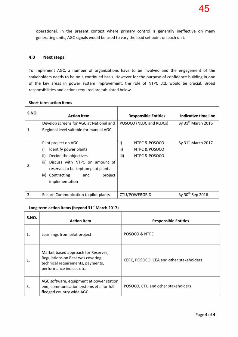
4.0 Next steps:
To implement AGC, a number of organizations have to be involved and the engagement of the
stakeholders needs to be on a continued basis. However for the purpose of confidence building in one
of the key areas in power system improvement, the role of NTPC Ltd. would be crucial. Broad
responsibilities and actions required are tabulated below.
Short term action items
S.NO.
Action item
Responsible Entities
Indicative time line
1.
Develop screens for AGC at National and
Regional level suitable for manual AGC
POSOCO (NLDC and RLDCs) By 31st March 2016
2.
Pilot project on AGC
i) Identify power plants
ii) Decide the objectives
iii) Discuss with NTPC on amount of
reserves to be kept on pilot plants
iv) Contracting and project
implementation
i) NTPC & POSOCO
ii) NTPC & POSOCO
iii) NTPC & POSOCO
By 31st March 2017
3. Ensure Communication to pilot plants CTU/POWERGRID By 30th Sep 2016
Long term action items (beyond 31st March 2017)
S.NO.
Action item
Responsible Entities
1. Learnings from pilot project
POSOCO & NTPC
2.
Market based approach for Reserves, Regulations on Reserves covering technical requirements, payments, performance indices etc.
CERC, POSOCO, CEA and other stakeholders
3. AGC software, equipment at power station end, communication systems etc. for full fledged country wide AGC
POSOCO, CTU and other stakeholders
45

46

47
48

49

50

Implementation of Automatic Generation Control (AGC)
POSOCO
19th – 20th January 2016 New Delhi
Related CERC documents
• Report of the Committee on Spinning Reserves
– 17th September 2015
– http://www.cercind.gov.in/2015/orders/Annexure‐%20SpinningReseves.pdf
• Roadmap to operationalise Reserves in the country
– 13th October 2015
– http://cercind.gov.in/2015/orders/SO_11.pdf
• Central Electricity Regulatory Commission (Ancillary
Services Operations) Regulations, 2015
– 13th August 2015
– http://cercind.gov.in/2015/regulation/Noti13.pdf
51
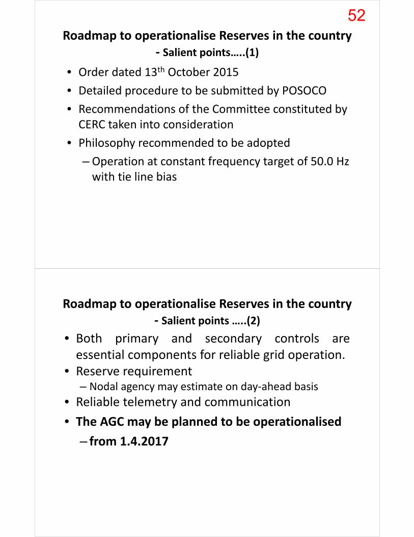
Roadmap to operationalise Reserves in the country‐ Salient points…..(1)
• Order dated 13th October 2015
• Detailed procedure to be submitted by POSOCO
• Recommendations of the Committee constituted by CERC taken into consideration
• Philosophy recommended to be adopted
–Operation at constant frequency target of 50.0 Hz with tie line bias
Roadmap to operationalise Reserves in the country‐ Salient points …..(2)
• Both primary and secondary controls areessential components for reliable grid operation.
• Reserve requirement– Nodal agency may estimate on day‐ahead basis
• Reliable telemetry and communication
• The AGC may be planned to be operationalised
– from 1.4.2017
52
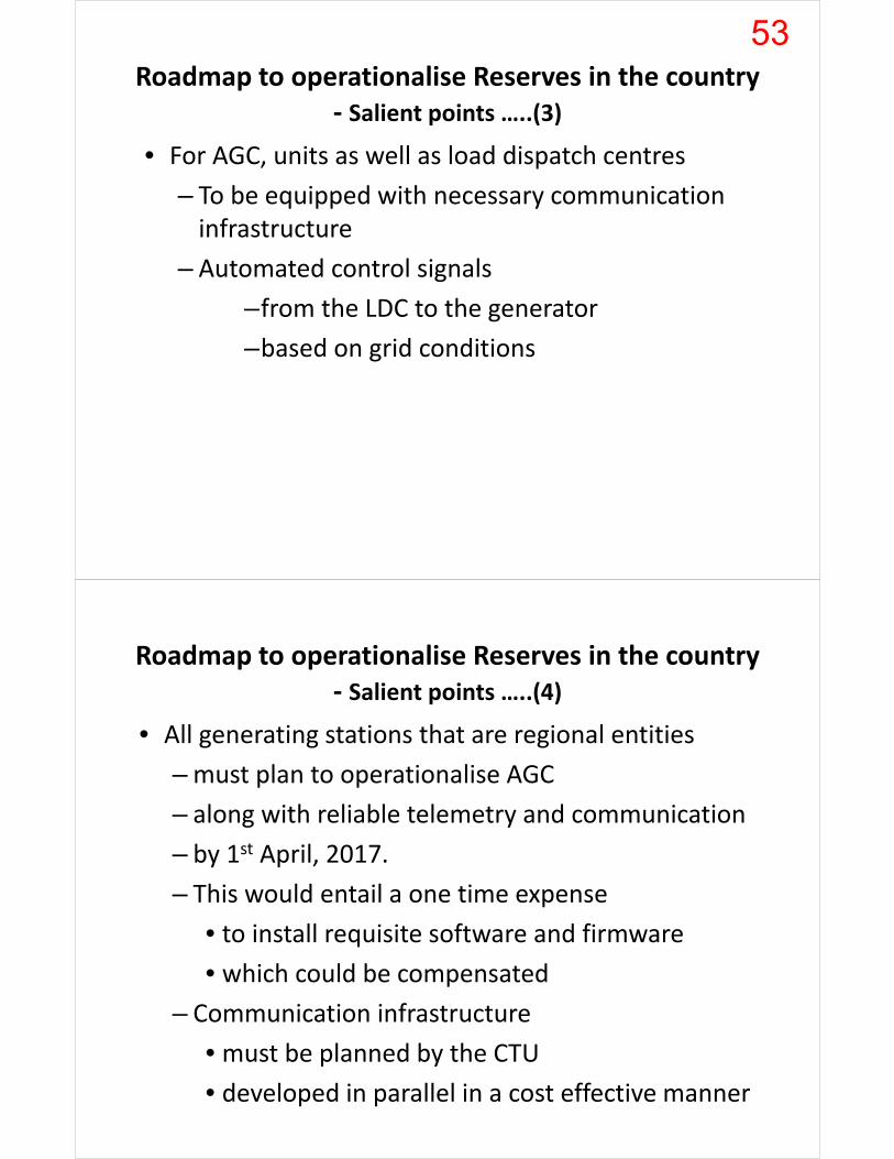
Roadmap to operationalise Reserves in the country‐ Salient points …..(3)
• For AGC, units as well as load dispatch centres
– To be equipped with necessary communication infrastructure
– Automated control signals
–from the LDC to the generator
–based on grid conditions
Roadmap to operationalise Reserves in the country‐ Salient points …..(4)
• All generating stations that are regional entities
–must plan to operationalise AGC
– along with reliable telemetry and communication
– by 1st April, 2017.
– This would entail a one time expense
• to install requisite software and firmware
• which could be compensated
– Communication infrastructure
• must be planned by the CTU
• developed in parallel in a cost effective manner
53
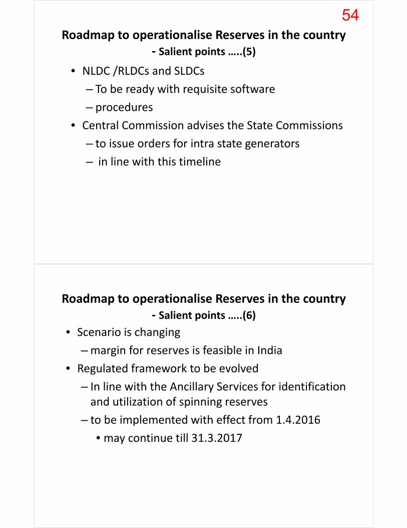
Roadmap to operationalise Reserves in the country‐ Salient points …..(5)
• NLDC /RLDCs and SLDCs
– To be ready with requisite software
– procedures
• Central Commission advises the State Commissions
– to issue orders for intra state generators
– in line with this timeline
Roadmap to operationalise Reserves in the country‐ Salient points …..(6)
• Scenario is changing
–margin for reserves is feasible in India
• Regulated framework to be evolved
– In line with the Ancillary Services for identification and utilization of spinning reserves
– to be implemented with effect from 1.4.2016
• may continue till 31.3.2017
54

Roadmap to operationalise Reserves in the country‐ Salient points …..(7)
• A market based framework for procuring reserves
– from 1st April 2017
– for achieving greater economy & efficiency in the system
– NLDC to commission a detailed study
• Tertiary control refers to manual change
– in the dispatching and unit commitment
– in order to restore the secondary control reserve
– Ancillary Services Regulation
Roadmap to operationalise Reserves in the country‐ Salient points…..(8)
• Proposed amendment to the Indian Electricity Grid Code (IEGC) – in respect of technical minimum
– Ramp up and Ramp down rates
– other important parameters for flexibility through regulations
55

Report of the Committee on Spinning Reserves‐ Salient points…..(1)
• Spinning Reserves
– may be maintained of requisite quantum
– depending upon the grid conditions
• The philosophy
– operation at constant frequency target of 50.0 Hz
with tie line bias
• The Spinning Reserve may be maintained,
– to start with at the regional level.
Report of the Committee on Spinning Reserves‐ Salient points…..(2)
• Each region should maintain secondary reserve
– corresponding to the largest unit size in the region
• Tertiary reserves
– should be maintained in a de‐centralized fashion by each state control area
– for at least 50% of the largest generating unit available in the state control area.
• More statistics provided in the next slides
56

Primary and Secondary Reserves
• Secondary Reserves (centralized approach)
– North : 800 MW
– East : 660 MW
– West : 800 MW
– South : 1000 MW
– North East : 363 MW
– Total : 3623 MW
• Primary Reserves (distributed )
– 4000 MW considering Ultra Mega Power Plant out
Tertiary Reserves (decentralized)
• All India level : 5218 MW
– NR : 1658 MW
– WR : 1353 MW
– SR : 1343 MW
– ER : 857 MW
– NER : 65 MW
• Reserves to be maintained at intra state level
57

>2000 MW 97%
>2500 MW 92%
>3000 MW 87%
>4000 MW 71%
>5000 MW 51%
>6000 MW 32%
Frequency profile, Deviations, ACE
• Frequency profile
• Deviations from the schedule
• Area Control Error (ACE) considering regions
58

Issues to be discussed and roadmap evolved
i. Should reserves be earmarked specifically?– 5000‐6000 MW UnRequisitioned Surplus (URS) – Earmark only on days when URS falls to low value
• Prohibit generation above 95‐98% of DC on these days
ii. Should most of the units be wired for AGC?iii. Need to define Area Control Error (ACE)
– Area Control Error (ACE) = ∆ P + k ∆fWhere ∆ P = (Actual Net Interchange, NIA )– (Scheduled Net Interchange, NIs )∆f = (Actual Frequency, FA – Scheduled Frequency, FS) in Hz k = Frequency Bias of Control Area in MW/Hz, usually with a negative sign.
Issues to be discussed and roadmap evolved
iv. Automatic Generation Control (AGC) software
– Implementation at NLDC level
• Equivalent to five (5) Regional AGCs
– Plant wise signals or unit‐wise signals
– Single point responsibility in case of plant wise signal
– Accurate value of ∆P (telemetery errors & redundancy in measurements)
v. Communication protocols and type of signals
vi. Security Constrained merit order
vii. Day Ahead earmarking of Reserves
59

Issues to be discussed and roadmap evolved
viii. Commercial treatment of units under AGC
– Normal scheduling process
– Ancillary Services (AS) despatch schedule
– AGC signals and its conversion to schedule
– Payment for units under AGC
– Commercial treatment of deviations from the schedule
– Sufficient incentives for units under AGC
ix. Pilot projects for better understanding
– Candidate stations in each region
– Data inputs for AGC
Possible candidates for secondary control
Region Secondary reserve required ‘MW’
No of power stations available for AGC
MW capacity available for AGC
Stationsavailable if variable cost > 250 paise/kWh only to be considered
Capacity available if variable cost > 250 paise/kWh
NR 800 13 11283 9 6282
WR 800 16 15121 3 2313
SR 1000 9 10490 2 1500
ER 660 6 6760 4 4260
NER 363 3 1101 2 375
Total 3623 47 44755 20 14730
60

Thank you
Sample Regional ACE data for 06th December, 2015
61
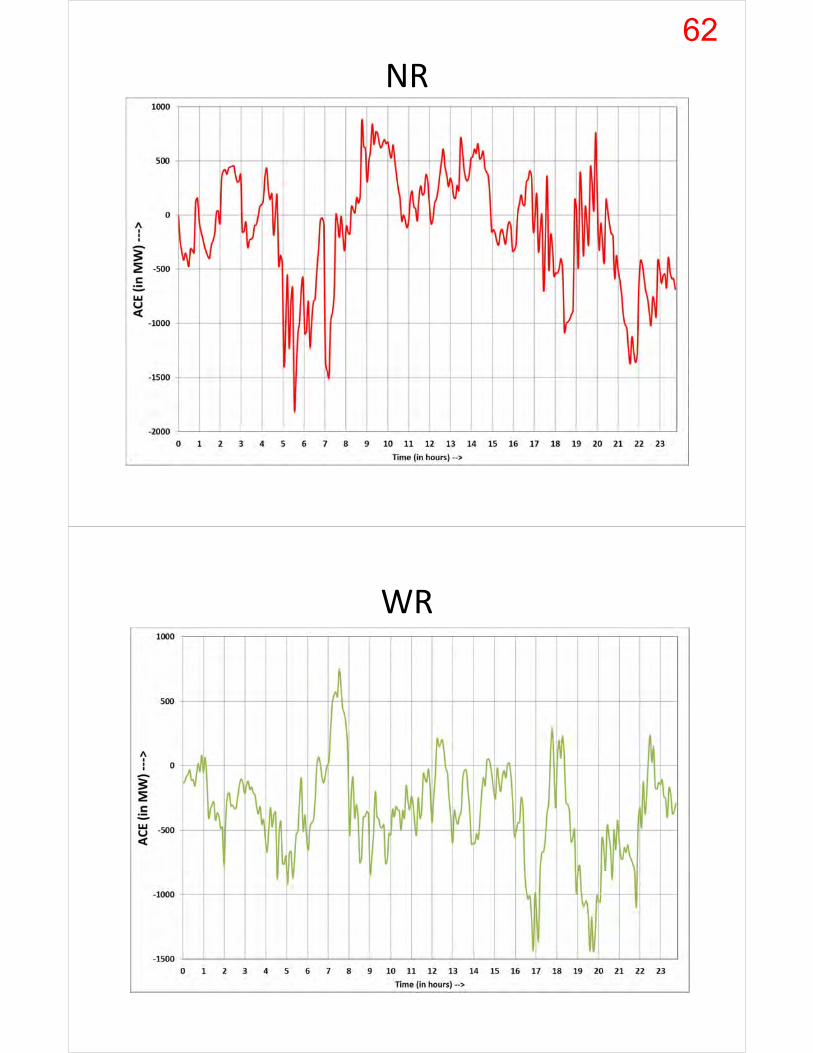
NR
WR
62
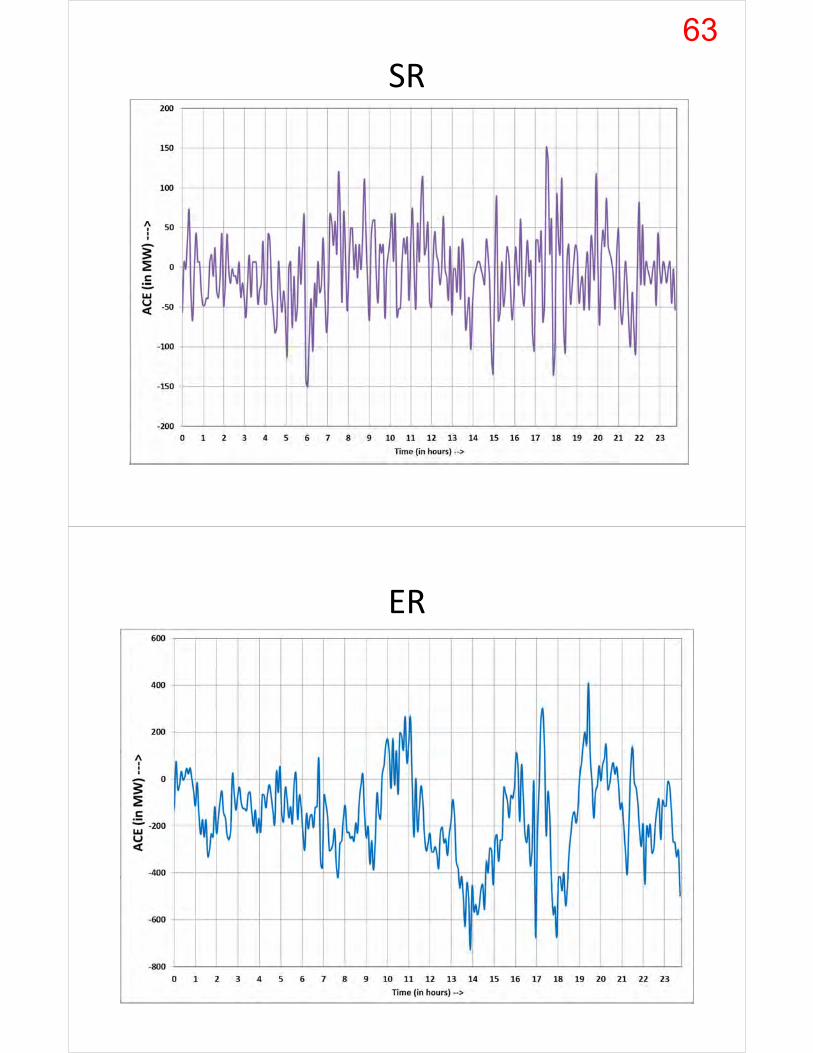
SR
ER
63

NER
Frequency profile over the years
64

65
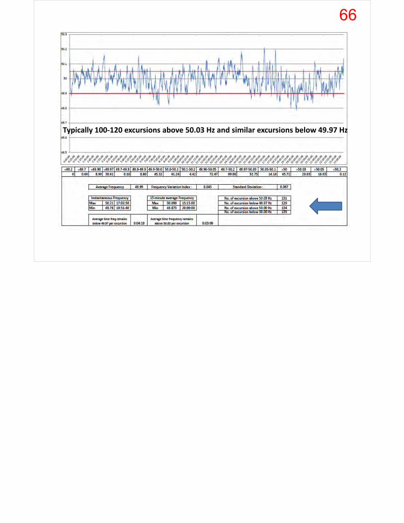
Typically 100‐120 excursions above 50.03 Hz and similar excursions below 49.97 Hz
66

Current Installed Generation CapacityNTPCOwned:39,352MW JVandSubsidiary:6196MW
• Incorporated in 1975 ; Pan India Presence
• 45,548 MW capacity under Operation ; 23,004 MW under Construction
• Ten (10) coal mine blocks
• 25,000 committed workforceSource: Central Electricity Authority (CEA)
67
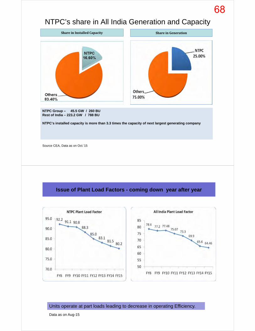
NTPC’s share in All India Generation and CapacityShareinInstalledCapacity ShareinGeneration
NTPC Group – 45.5 GW / 260 BURest of India – 223.2 GW / 788 BU
NTPC’s installed capacity is more than 3.3 times the capacity of next largest generating company
Source CEA, Data as on Oct.’15
Issue of Plant Load Factors - coming down year after year
Units operate at part loads leading to decrease in operating Efficiency.
Data as on Aug-15
68

REGIONS STATIONAverage URS in
FY16(MW)
Energy Charge Rate
Paise/KwhDadri 590 337-365
Rihand 231 155-192Unchahar 153 261-270
Jhajjar 341Singrauli 61 130-135
1376
Mouda 679 248-258Sipat 174 110-115
Korba 17 98-102Vindhyachal 523 131-138
1393Ramagundam 131 224-231
Simhadri 220 247-250
Vallur 8
359Farakka 245 276-280
Kahalgaon 371 261-273Barh-2 137 313-315
Talcher Kaniha 51 125-130803
NR-800 MW out of 7660 MW Cap Available for Spinning
Res.CAP.(20Units)
WR-800 MW- Av. Cap 8380 MW (16 Units)
SR-1000 MW - Av. Cap 6100MW (14Units)
ER-660 MW-Av Cap for Spinning Res. 3260 MW (8
Units)
Region wise break up of URS
Load following
Regulation
Increasing Variability of “Net / Residual Load” with large RES integration
Conventional Generation
Load Demand – RE Power Injection + System Losses=
69

Three types of Imbalance control
Challenges for Conventional Generation:Major challenges which will be faced by NTPC in order to flex conventional generation to balance the increased variability & intermittency of “Net Load”
Issues Expectations / Apprehensions
Spinning ReserveUse under Normal conditionSecondary (AGC) Control:i) Regulation services: Continuous
& frequently demanded.
ii) Load Following Services:
Mostly higher VC stations will be earmarked.
i) Continuous response to balance load-Gen. If reserve is kept on many m/cs in acontrol area, miniscule variations (1% orless) will be demanded & not pose anydifficulty.
ii) a) Quantum of Load ramp up / down willbe high. Need to keep full auxiliariesrunning even when in part load.
b) Open cycle operation of gas plants maybe called for but its cost ??
70
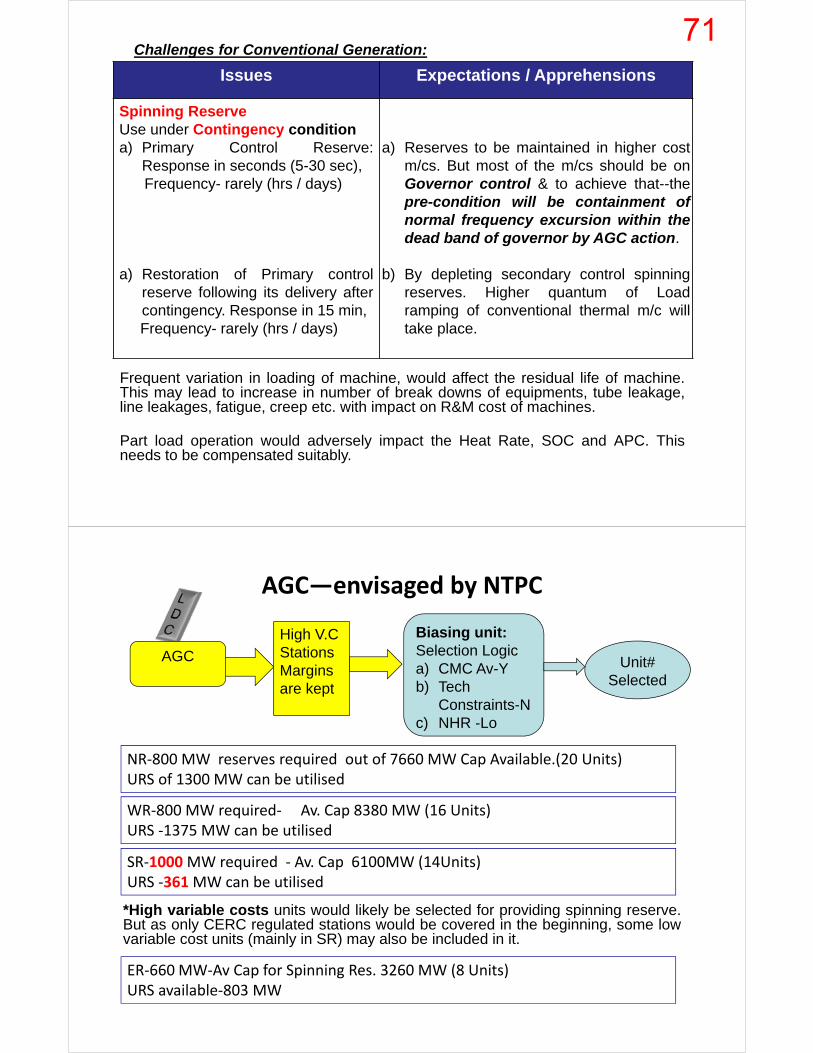
Challenges for Conventional Generation:
Issues Expectations / Apprehensions
Spinning ReserveUse under Contingency conditiona) Primary Control Reserve:
Response in seconds (5-30 sec),Frequency- rarely (hrs / days)
a) Restoration of Primary controlreserve following its delivery aftercontingency. Response in 15 min,Frequency- rarely (hrs / days)
a) Reserves to be maintained in higher costm/cs. But most of the m/cs should be onGovernor control & to achieve that--thepre-condition will be containment ofnormal frequency excursion within thedead band of governor by AGC action.
b) By depleting secondary control spinningreserves. Higher quantum of Loadramping of conventional thermal m/c willtake place.
Frequent variation in loading of machine, would affect the residual life of machine.This may lead to increase in number of break downs of equipments, tube leakage,line leakages, fatigue, creep etc. with impact on R&M cost of machines.
Part load operation would adversely impact the Heat Rate, SOC and APC. Thisneeds to be compensated suitably.
AGC—envisaged by NTPC
NR‐800 MW reserves required out of 7660 MW Cap Available.(20 Units)URS of 1300 MW can be utilised
WR‐800 MW required‐ Av. Cap 8380 MW (16 Units)URS ‐1375 MW can be utilised
SR‐1000MW required ‐ Av. Cap 6100MW (14Units)URS ‐361MW can be utilised
ER‐660 MW‐Av Cap for Spinning Res. 3260 MW (8 Units)URS available‐803 MW
AGC
High V.C StationsMargins are kept
Biasing unit:Selection Logica) CMC Av-Yb) Tech
Constraints-Nc) NHR -Lo
Unit#Selected
*High variable costs units would likely be selected for providing spinning reserve.But as only CERC regulated stations would be covered in the beginning, some lowvariable cost units (mainly in SR) may also be included in it.
71

Operating band for Spinning Reserve & Automatic Generation Control (AGC)
Scope of AGC and communication Infrastructure/interface
In the scope of NTPCNTPC’s SCOPE
In the scope of NLDC/RLDC
72
THANK YOU.
Spinning Reserves
Time for mills from start to coal firing varies from 5 Min to >30 Min
It is desirable to have larger number of units for spinning reserves with
small quantum of reserve requirement per unit.
This will enable us to utilize the reserve available in auxiliaries
However, keeping large margins in unit/station auxiliaries will increase
the APC.A tradeoff between APC and margins requirements for
spinning reserves may be done.
In some cases wherein additional mill is required to be taken in
service , it may be difficult to maintain the timeline for spinning
reserves . (30 sec-15 min)(Unchahar St-2,Vind-St-2,Ramagundam St-
1 etc.)
73
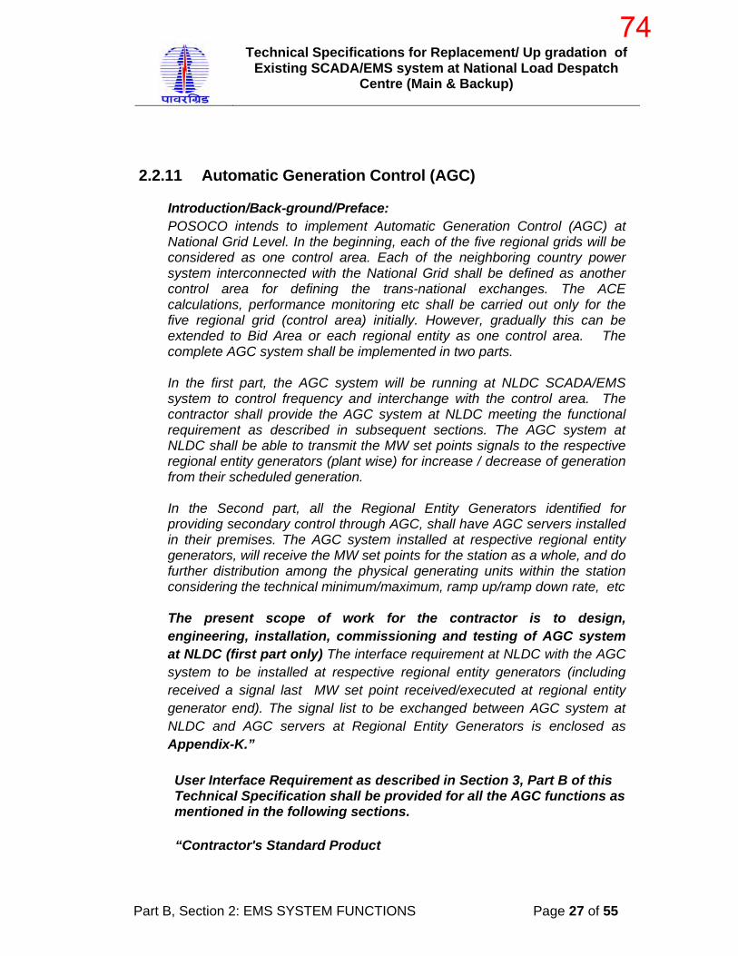
Technical Specifications for Replacement/ Up gradation of Existing SCADA/EMS system at National Load Despatch
Centre (Main & Backup)
Part B, Section 2: EMS SYSTEM FUNCTIONS Page 27 of 55
2.2.11 Automatic Generation Control (AGC) Introduction/Back-ground/Preface:
POSOCO intends to implement Automatic Generation Control (AGC) at National Grid Level. In the beginning, each of the five regional grids will be considered as one control area. Each of the neighboring country power system interconnected with the National Grid shall be defined as another control area for defining the trans-national exchanges. The ACE calculations, performance monitoring etc shall be carried out only for the five regional grid (control area) initially. However, gradually this can be extended to Bid Area or each regional entity as one control area. The complete AGC system shall be implemented in two parts.
In the first part, the AGC system will be running at NLDC SCADA/EMS system to control frequency and interchange with the control area. The contractor shall provide the AGC system at NLDC meeting the functional requirement as described in subsequent sections. The AGC system at NLDC shall be able to transmit the MW set points signals to the respective regional entity generators (plant wise) for increase / decrease of generation from their scheduled generation.
In the Second part, all the Regional Entity Generators identified for providing secondary control through AGC, shall have AGC servers installed in their premises. The AGC system installed at respective regional entity generators, will receive the MW set points for the station as a whole, and do further distribution among the physical generating units within the station considering the technical minimum/maximum, ramp up/ramp down rate, etc
The present scope of work for the contractor is to design, engineering, installation, commissioning and testing of AGC system at NLDC (first part only) The interface requirement at NLDC with the AGC system to be installed at respective regional entity generators (including received a signal last MW set point received/executed at regional entity generator end). The signal list to be exchanged between AGC system at NLDC and AGC servers at Regional Entity Generators is enclosed as Appendix-K.”
User Interface Requirement as described in Section 3, Part B of this Technical Specification shall be provided for all the AGC functions as mentioned in the following sections.
“Contractor's Standard Product
74

Technical Specifications for Replacement/ Up gradation of Existing SCADA/EMS system at National Load Despatch
Centre (Main & Backup)
Part B, Section 2: EMS SYSTEM FUNCTIONS Page 28 of 55
Bidders are encouraged to supply standard, unmodified products that meet or exceed the Specification requirements. These products may be provided from the bidder's in-house baseline offerings. Alternatively, they may be provided by the computer manufacturer and established third-party software suppliers. Bidders shall describe all standard; unmodified products proposed and shall highlight those features that exceed the Specification requirements. Although the bidder is encouraged to use as much standard hardware and software as possible, the proposal will be judged by its conformance to the functional requirement of Specification. The proposal shall clearly identify all deviations from the Specification to help Employer evaluate the degree of conformance of the Bidder's offering.”
2.2.11.1 Generation Control (described in this section):
The principle Generation Control functions described herein include:
• Operations Monitor (OM) • Automatic Generation Control (AGC) • Reserve Monitoring (RM)
These functions address the NLDC operational objective of Reliable Power System Operation. These functions shall monitor and coordinate generation while supporting regional and national LDC operating personnel. Although the Generation Control functions, specifically AGC, will execute in an open-loop advisory mode initially, the Contractor shall provide the software, database, and user interface to perform closed-loop generation control in the future. The user shall be able to test and activate AGC in a closed-loop mode as control equipment becomes available in the field. The AGC calculation shall also take into account transmission congestion/ constraints.
Generation Control shall assist the NLDC/RLDC dispatchers to maintain scheduled frequency and scheduled power interchanges by:
(1) Running the ISGS according to ABT schedule (2) Allocating the generation raise/ lower signal within each RLDC's
area of jurisdiction (3) Using available generation to maintain power system frequency (4) Monitoring available spinning and non-spinning reserve
capacities.
Within this context, the principle real-time dispatching activities of the LDC are summarized as follows:
75

Technical Specifications for Replacement/ Up gradation of Existing SCADA/EMS system at National Load Despatch
Centre (Main & Backup)
Part B, Section 2: EMS SYSTEM FUNCTIONS Page 29 of 55
(a) Activities: (1) Monitor the Region's generating resources, reserves, loads,
, inter-regional imports/exports, and frequency (2) Monitor each Area’s actual net interchange versus its
scheduled value (obligation) and maintain records of interchange errors
(3) Dispatch the region's ISGS (4) Enter into import/export transactions with other regions (5) Send ISGS actual unit output data to the NLDC for National
monitoring (6) Send directives to the region (for example, to change
generation and shed/restore load). 2.2.11.1.1 Operations Monitor
Operations Monitor (OM) shall provide shift operators/supervisors with a continual and accurate description of the demand/supply situation within their areas of responsibility.
OM shall produce information for display (numerical and trending) and for historical records. All the items listed below shall be calculated and monitored at the NLDC, which shall receive the required telemetered, calculated as well as user-entered information from all relevant sources comprising the hierarchical SCADA/EMS.
The following calculations as a minimum shall be performed at an adjustable periodicity (initially set to 1 minute):
(b) Actual Generation MW: (1) Total for all India (2) Total for each region (3) Total for each company/part of company, ISGS, regional
entity and the users' share breakdown. Generation shall be mentioned fuel-wise also. (c) Unallocated ISGS Generation MW: (1) Total for all India (2) Total for each region, control area.
76
Technical Specifications for Replacement/ Up gradation of Existing SCADA/EMS system at National Load Despatch
Centre (Main & Backup)
Part B, Section 2: EMS SYSTEM FUNCTIONS Page 30 of 55
(3) Total for each Company/part of company, ISGS, regional entity and user.
(4) Total for Cross Border, International. Unallocated Generation shall be mentioned fuel-wise also. (d) Net Interchange MW (actual, scheduled, and deviation from
schedule): Net Interchange definitions and calculations shall be user-definable:
(1) Net for all India and breakdown per region and control area. (e) Actual Drawal MW (including transmission losses): (1) Total for all India (2) Total for each region. (3) Total for regional entities. (4) Total for Inter-national. (f) Area Control Error (ACE): ACE for 6 operating (5-Five Regions &
1- one NLDC)and processed ACE values shall be calculated based on actual frequency, actual net interchange, scheduled frequency, and scheduled net interchange. Control areas and associated ACE calculations will be defined by Employer during project implementation.
(1) For all India (2) For each region.
The NLDC shall retain the operational characteristics of each ISGS generating unit. The RLDCs shall report changes to unit characteristics to the NLDC as they occur. Each RLDC shall maintain its own unit information.
2.2.11.1.2 Automatic Generation Control Functions:
The primary objective is that AGC shall provide supplementary or secondary control action, which attempts to maintain the steady state values at specific levels. Primary control action for short-term swings shall be provided by the governors of the unit prime movers. The primary purpose of AGC to be delivered under this project is to adjust generation in response to changes in area load and Interchange requirement and to return frequency to its original value and maintain the difference between the constant frequency control error and the constant net interchange error within an acceptable range. This difference is the Area Control Error or ACE.
77
Technical Specifications for Replacement/ Up gradation of Existing SCADA/EMS system at National Load Despatch
Centre (Main & Backup)
Part B, Section 2: EMS SYSTEM FUNCTIONS Page 31 of 55
Automatic Generation Control (AGC) shall have the ability to: (a) Execute in open-loop, i.e., without sending control signals to the
generating units (b) Perform standard load-frequency control calculations if the
generating capacity exceeds the load requirements, i.e., maintain scheduled frequency and net interchanges within prescribed values.
Initially, AGC will operate in open-loop, i.e., the control signals determined by functions will not be sent to the generating units and/or power plants. Full capability shall be provided, however, for the AGC functions to be field-upgradable to closed-loop operation without any need of additional computer software and/or hardware if, at a later date, Employer chooses to do so.
During normal open-loop operation (generation capacity greater than load), NLDC dispatchers shall be provided with the ability to manually select either the Load Frequency Control Mode. AGC shall compute the desired MW increase or decrease at each generating unit. The required MW changes shall then be totalled on a power station basis and communicated. The dispatcher shall be provided with the ability to validate or manually modify the MW changes required at each generating unit and power station. Upon dispatcher request, the MW change requirements shall be sent to the power station operators for subsequent control action.
During periods characterized by low frequency and generation capacity deficiency, AGC shall compute the amount of MW load reduction to be implemented. This information shall be displayed/ sent at the LDCs and, in addition, shall be automatically made available as input to the SCADA and ICCP.
At the NLDC, the Generation Control applications shall be fully implemented to allow the dispatchers to maintain the scheduled frequency and net interchanges within the prescribed limits. At the NLDC the capability shall be provided for the dispatcher to monitor the execution of the Generation Control applications within the RLDCs through periodically and on-demand updated Generation/Load Summary displays. Data for each generating unit region wise shall be displayed.
AGC shall retrieves and processes SCADA data and also trigger the rest of the AGC sequence, which shall be user configurable (initially every five minute), which includes:
• ACE calculations.
78
Technical Specifications for Replacement/ Up gradation of Existing SCADA/EMS system at National Load Despatch
Centre (Main & Backup)
Part B, Section 2: EMS SYSTEM FUNCTIONS Page 32 of 55
• Issue of controls.
• Reserve Monitor.
AGC shall be capable of providing supplementary control that automatically adjusts the power output levels of identified generators within the defined control area in response to Area Control Error. AGC shall account for the number of generating units and tie lines within a control area. Automatic Generation Control (AGC) shall have the ability to (through simple graphical user interface):
(a) Select/ Modify the AGC Status of operation
System Operator/User shall be able to select or modify one of the following AGC Status, either:
a. ON —AGC is fully functional and control command are
issued.[ This will be enabled once the AGC system at Regional Entity Generators is in service]]
b. OFF — Off Control. AGC is not functional, but issues no controls.
c. MONITOR — Monitor Control. AGC is fully functional,
except no controls are issued (i.e., Monitor only).
On Selection the new status shall became active, next AGC cycle.
(b) Select the type of computation for ACE (tie-line bias
control, frequency control only, or tie-line control only) Three types of dispatcher selectable ACE calculation procedures shall be provided as follows:
The total plant allocation action required in AGC's control cycle shall be determined at the NLDC and assignments made to individual plants and units based on their control and operating status, operating limits, response rate limits, and deviation from schedule/ desired loading. Plants and unit control modes shall initially be set by default to "Off Control." Their limits, however, shall be dispatcher selectable and the capability shall be provided to adjust the parameters of AGC through user interface. The plant allocation function shall continuously determine MW requirements both for plants under NLDC jurisdiction and RLDC jurisdiction.
Three types of dispatcher selectable ACE calculation procedures shall be provided as follows:
79

Technical Specifications for Replacement/ Up gradation of Existing SCADA/EMS system at National Load Despatch
Centre (Main & Backup)
Part B, Section 2: EMS SYSTEM FUNCTIONS Page 33 of 55
(a) Tie-Line Bias Control, where ACE is calculated from the following formula:
ACE = (Ia - Is) + 10 Bf (fa - fs) where: ACE = positive value for excess generation Ia = actual net interchange (positive value for export) Is = scheduled net interchange (positive value for export) Bf = frequency bias coefficient in MW/0.1 Hz (positive
value) fa = actual system frequency fs = scheduled system frequency (b) Frequency Control only, where ACE is calculated by setting (Ia -
Is) to zero (c) Tie-Line Control only, where ACE is calculated by setting Bf(fa -
fs) to zero.
There shall be suitable display at operator screen to monitor the following parameters: • Status and Mode of AGC Operation for each of the Area • Graphical trend of ACE for each area • Total Load and Generation of the respective area • Spinning reserve and operating reserve requirement of the respective area • Spinning reserve and operating reserve availability of the respective area
Although, during initial operation AGC will be executed in open-loop, ACE shall be conditioned (to produce a processed ACE) such that generator control action, if it were to be implemented, may occur only as necessary to reduce the magnitude of ACE with a minimum of governor control action. The AGC algorithm shall reduce governor action due to ACE noise and still respond to fast real changes of ACE by using digitally filtered adaptive and predictive controls. For each controllable unit in the system, a dispatcher selectable unit control mode shall be provided.
Actual control of a given unit shall be a function of the AGC control mode and the individual unit control mode. The capability shall be provided for software maintenance personnel to enter e.g. gains, regulating factors, assist factors, dead band values, program execution periods, and other factors as appropriate through interactive User Interface.
Initially, the length of the AGC cycle will be large enough to enable NLDC dispatchers and power plant operators to implement the
80

Technical Specifications for Replacement/ Up gradation of Existing SCADA/EMS system at National Load Despatch
Centre (Main & Backup)
Part B, Section 2: EMS SYSTEM FUNCTIONS Page 34 of 55
recommended control actions. At a later date, when AGC operates closed-loop control, the execution cycle will be reduced in accordance with the real-time control requirements. In closed-loop implementation, it shall monitor control performance. .
2.2.11.2 AGC Measurements
All unit measurements and parameters will be on the basis of telemetered generation as defined by Employer during project implementation. The following telemetered data shall be provided to the Area Control Error computation algorithm:
(a) Tie-line power flow values (b) Schedule generation of each Unit/Plant
(b) Actual MW generation of each unit 2.2.11.2.1 Dispatcher Inputs to AGC
The Despatcher data entry requirements to AGC shall comprise, but not be limited to, the following functions:
(a) Select the AGC mode of operation (b) Choose the type of computation for ACE (tie-line bias control,
frequency control only, or tie-line control only) (c) Select generating unit control mode (this capability shall be
initially disabled) (d) Enter actual interchange for tie-line values normally not
telemetered (e) Enter generating unit limits (f) Enter unit response rates (this capability initially may be disabled) (g) Deactivate and activate telemetry values (both analog and status) All dispatcher entries shall be subject to validity checking. . 2.2.11.2.2 Generating Unit Control Modes AGC shall recognize the following generating unit control modes: (a) Not Available: The unit is out-of-service and is unavailable to the
user.
81

Technical Specifications for Replacement/ Up gradation of Existing SCADA/EMS system at National Load Despatch
Centre (Main & Backup)
Part B, Section 2: EMS SYSTEM FUNCTIONS Page 35 of 55
(b) Off-Line: The unit is off-line but can be brought on-line if needed. (c) Plant Control: The unit is on-line but is directly under plant control.
The desired generation for the unit is determined by the plant operator.
(d) On Control: The unit is on automatic generation control and
controlled by AGC within the operating limit settings. .
The unit is controlled by AGC to follow the load based on its capacity. The user shall be prevented from placing a unit on control unless the plant operator has the unit on AGC.
2.2.11.2.3 Generating Unit Limits The following generating unit limits shall be recognized: (a) Total Capability: A user-entered limit indicating the maximum
output the unit can maintain. (b) Operating High Limit: A limit indicating the highest output the unit
can maintain with the equipment in service at the time. (c) Operating Low Limit: A limit indicating the lowest output the unit
can maintain with the equipment in service at the time. (d) Low Capability: A user-entered limit indicating the minimum
output that can be maintained. (e) Response: A user-entered limit representing the maximum
sustained rate-of-change-of-output for the unit.
A check shall be performed on limits (a) through (d) to determine that the values are consistent with one another. An alarm shall be generated whenever they are not consistent and control of the affected generating unit shall be suspended until the limits are corrected.
2.2.11.2.4 Turbine Control Logic
The desired generation for each generating unit shall be computed using the unit's base generation, , the change in total generation since the last execution of the function, the unit's regulating participation factor, and PACE as follows:
UDG = UBG + - (URPF * PACE) where:
82
Technical Specifications for Replacement/ Up gradation of Existing SCADA/EMS system at National Load Despatch
Centre (Main & Backup)
Part B, Section 2: EMS SYSTEM FUNCTIONS Page 36 of 55
UDG = Unit's Desired Generation UBG = Unit's Base Generation URPF = Unit's Regulating Participation Factor PACE = Processed Area Control Error.
Regulating participation factors shall normally be calculated in proportion to the generating units' respective response rates. The user shall be able to enter a response rate for the calculation of each unit's regulating participation factor, but the manually entered values shall not be used for other functions requiring response rates (such as Reserve Monitoring). All regulating participation factors shall be normalized based on the units in the Fixed Load with Regulation. The unit's desired generation and all of its component terms shall be displayable.
When AGC is implemented in closed-loop mode in the future, generating units shall be driven to their desired generation in a manner consistent with the control type and the unit control modes and limits. The response characteristics of each unit shall be modelled to: (1) anticipate unit response, (2) minimize the control action that has to be sent to each unit, (3) avoid overshoot, and (4) determine when a unit fails to respond. The response models shall include stored energy effects so as to allow selected units to move faster than their response rate limit for a short period. Unit dead bands and other logic shall be used to avoid issuing control signals smaller than the control resolution of units while at the same time ensuring that control errors do not accumulate.
2.2.11.2.5 Generating Unit Control Signals
In the Future, some generating Plants shall be controlled by a set point representing the Plant’s desired generation. A set point for each unit of such plant in control shall be calculated at plant level and based on the change sent to generating plant by AGC. The selection of set point or raise/lower control shall be made on a Plant basis by the dispatcher.
2.2.11.2.6 Control Suspension/Trip
If data cannot be collected from a generating plant or if a unit has not responded within a programmer-adjustable period, the plant shall be set to Off Control and an alarm generated. Excessive deviations of frequency or ACE shall cause a suspension in control output to all generating plants until frequency and ACE are normal. The limit for these deviations shall be changeable by the dispatcher. AGC shall be suspended if the measurement from any tie line (except in the Constant Frequency control mode) or the primary frequency source (except in the Constant Net Interchange control mode) has failed. If AGC suspends control for longer than a dispatcher-changeable time period, AGC shall be tripped (i.e., control output to all plants shall cease), thereby requiring manual intervention to restore control. If the
83

Technical Specifications for Replacement/ Up gradation of Existing SCADA/EMS system at National Load Despatch
Centre (Main & Backup)
Part B, Section 2: EMS SYSTEM FUNCTIONS Page 37 of 55
failed measurement becomes valid prior to the timeout, or if the user enters a substitute value or selects a redundant source for the telemetry prior to the timeout, or if excessive values return to within limits prior to the timeout, AGC shall resume and provide appropriate messages describing these events.
The user shall be able to trip AGC at any time. When AGC is suspended or trips for any reason, all calculations including ACE shall continue to be performed. All actions that cause a suspension or trip shall be alarmed with a message identifying the reason for the action.
2.2.11.2.7 AGC Performance Monitor
Control performance shall be monitored against the defined Performance Criteria. These standards are based on the combination of the ACE and the frequency deviation averages over the past twelve months. The AGC software shall have a Performance Monitor function and displays the results. It shall be possible to generate periodic reports of the performance parameters. Statistics shall be maintained as required to complete the defined Performance Criteria. These statistics shall be maintained for presentation on displays and output to a printer.
2.2.11.2.8 Non-telemetered interchange / generation:
The operator shall be able to enter manually the non-telemetered interchange or generation values.
2.2.11.2.9 Specifying Area Scheduled Frequency:
It shall be possible to specify the area scheduled frequency for each of the control area.
2.2.11.2.10 Specifying Area Frequency Bias Coefficient (Bf)
The system operator shall be able to specify whether the area frequency bias should be calculated by software or whether it should be manually entered, and to enter the frequency bias if the manual entry is selected.. The area frequency bias is represented in MW/0.1Hz.
2.2.11.2.11 Entering Reserve Requirements
The operator shall be able to enter/specify the Spinning reserve / Operating Reserve requirement for each of the Control Area.
2.2.11.2.12 Entering Operating Area Response Rate Requirement
The system operator shall be able to specify/ modify the operating area response rate requirement to be used by AGC. This value defines the
84
Technical Specifications for Replacement/ Up gradation of Existing SCADA/EMS system at National Load Despatch
Centre (Main & Backup)
Part B, Section 2: EMS SYSTEM FUNCTIONS Page 38 of 55
minimum short-term rate in both the upward and downward direction for the entire operating area.
2.2.11.2.13 Selecting/Modifying a Generating Station Regulating
Participation Factor:
The operator shall be able to select or modify the generating station relative participation during proportional regulation duty. Alternately operator shall be able to define priority list for assigning the regulation requirement. The operator shall have the option to enter the PLC's Generators regulation participation factor (RPF) or use a RPF computed by the AGC function or list of priorities.
AGC shall calculate regulation participation factors for those Generators that are not using manually entered values. The manually entered values for the Generator that can regulate are added up and subtracted from 100. The amount left over is divided up among the remaining Generators that can regulate, using calculated factors in proportion to the Generators nominal up response rates. The resulting values are normalized over the set of Generators that are actually regulating (within each regulation priority) for that given cycle, to come up with the final participation factors used for the cycle.
2.2.11.2.14 Specify Jointly Owned Unit Operation
It shall be possible to specify some generating station for jointly owned unit operation (e.g.; SASAN UMPP which has shares in more than one control area). In such cases the generating unit shall participate for regulation for all the control area owns the generating station.
2.2.11.2.15 Interfacing with the Scheduling Software at NLDC:
AGC software at NLDC shall design a suitable interface with Scheduling Software in line with section 8.0 web design at NLDC to extract the following inputs for each 15 minute time block period:
• Declared Capacity of the Generating station ( DC) • Ramp Up / Ramp Down Rate • Base Point Generation ( Schedule Generation)
2.2.11.3 Real-Time Dispatch
The NLDC shall calculate the generation requirements for the participating ISGS based on ACE. AGC for real-time dispatch shall be
85
Technical Specifications for Replacement/ Up gradation of Existing SCADA/EMS system at National Load Despatch
Centre (Main & Backup)
Part B, Section 2: EMS SYSTEM FUNCTIONS Page 39 of 55
performed at an adjustable periodicity (initially 5 minutes) or upon the occurrence of any of the following events, providing that at least 30 seconds has elapsed since the last AGC:
(a) Significant change in system generation/ Transmission Network
(b) Significant change in actual net interchange (c) On demand by the user. (d) Dispatcher request
(e) Every Quarter of an hour/ Every Time block of ABT (f) A significant (software selectable) change in system load
since the last dispatch calculation (g) A significant change in actual net interchange since the last
dispatch (h) Significant Change in Transmission Network
2.2.11.4 Reserve Monitoring
The Reserve Monitoring (RM) function shall account for available generation capacity and system reserves both system-wise and by individual generating Plant/unit. Its sizing and data interfaces shall be coordinated with OM and Interchange Scheduling & ABT scheduling. This function shall obtain input data, perform necessary calculations, and produce the results for each Plant/ generator. Reserve Monitoring shall compute the following: (a) Plant/Generating capacity: The maximum MW output that can be committed within present operating constraints associated with the unit. This number can be manually entered by the dispatcher. (b) Spinning reserve: The total on-line synchronized generation reserve The ability shall exist for this function to be executed periodically (user-adjustable), on-demand, and by event trigger, e.g., each time an unscheduled unit tripping takes place.
2.2.11.4.1 Reserve Monitoring Inputs
The input data required by the Reserve Monitoring function shall be obtained automatically, from SCADA, or manually entered by the dispatcher. The input data shall include: (a) Current MW output of each generating unit (b) Maximum instantaneous MW available on each generating unit
86
Technical Specifications for Replacement/ Up gradation of Existing SCADA/EMS system at National Load Despatch
Centre (Main & Backup)
Part B, Section 2: EMS SYSTEM FUNCTIONS Page 40 of 55
(c) Parameter data, e.g., rated MW capacity for each unit, Nominal reserve, MW rate-of-change for each unit. (d) Forecasted Region-wide load and scheduled interchanges with neighbouring area for the next time period. 2.2.11.4.2 Reserve Monitoring Outputs The outputs shall consist of the calculated values of capacity and spinning reserves both for each plant and for the entire Area. The various reserve values shall be presented to the operator on User Interface displays. 2.2.11.4.3 Reserve Monitoring Alarms Alarms shall be generated when the following system conditions exist: (a) Spinning reserve less than the nominal reserve (b) Capacity for the next tile period insufficient to meet forecasted load and scheduled interchange as calculated in the middle of time period.
2.2.11.5 Production Statistics
Production Statistics (PS) shall be provided at the NLDC to maintain an accurate accounting of relevant production performance, production cost, plant availability factor, scheduled vs actual generation, and daily/ monthly generation regulation participation. Results shall be saved for display and trending and historical purposes and for daily and monthly reports. The following results shall be available at the end of the hour on a plant/unit, and regional basis: (a) Actual generation in net MWh (b) Actual and schedule generation
2.3 Dispatcher Training Simulator
A Dispatcher Training Simulator (DTS) shall be provided for Control Centre computer system training during power system normal, emergency, restoration activities. The major DTS features shall include:
(a) A Power System Model (PSM) that simulates the power system in a realistic manner, including its response to simulated events, Instructor actions, and Trainee actions. PSM response shall be identical to the response observed by the dispatcher in the actual computer system environment. The User Interface shall also be identical to that of the production system in order to provide a realistic and immersive training simulation.
87
OSI Corporate Overview
January 19, 2016
88
89

20-JAN-2016
Brain Storming Session for implementation of AGC in India
New DELHI
Indranil BANDYO
90

Unrestricted © Siemens AG 2014 All rights reserved. Answers for infrastructure and cities.
Spectrum PowerTM 7Power Applications for Transmission System Operators
Unrestricted © Siemens AG 2014 All rights reserved.
Page 2 Energy Management Division – Smart Grid Solutions
Spectrum Power™ 7 Power Applications
Overview
The Spectrum Power™ Power Applications suiteprovides the complete functionalities for:
• load frequency control, i.e. for maintaining real-time equilibrium between generation and load, whilst maintaining an optimum generation dispatch and scheduled interchange, and for
• generation dispatch control, i.e. for satisfying real-time ancillary requirements, e.g. regulating power, whilst meeting energy delivery contracts.
91
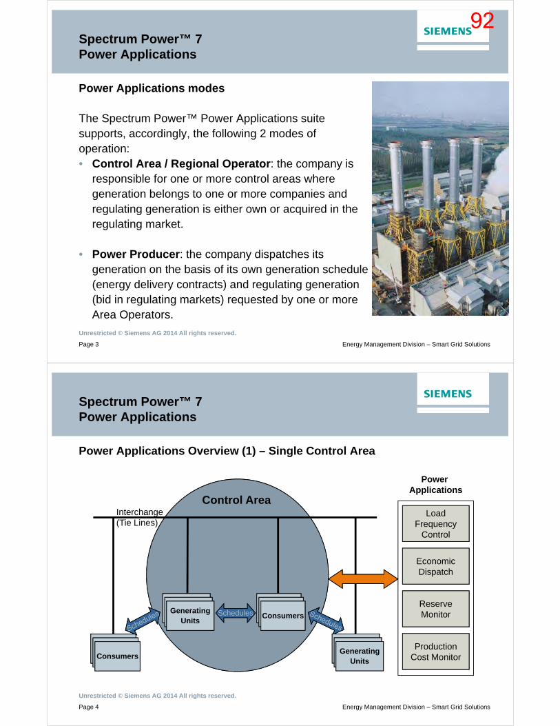
Unrestricted © Siemens AG 2014 All rights reserved.
Page 3 Energy Management Division – Smart Grid Solutions
Spectrum Power™ 7 Power Applications
Power Applications modes
The Spectrum Power™ Power Applications suitesupports, accordingly, the following 2 modes ofoperation:• Control Area / Regional Operator: the company is
responsible for one or more control areas where generation belongs to one or more companies and regulating generation is either own or acquired in the regulating market.
• Power Producer: the company dispatches its generation on the basis of its own generation schedule (energy delivery contracts) and regulating generation (bid in regulating markets) requested by one or more Area Operators.
Unrestricted © Siemens AG 2014 All rights reserved.
Page 4 Energy Management Division – Smart Grid Solutions
Spectrum Power™ 7 Power Applications
Power Applications Overview (1) – Single Control Area
Consumers
Control Area
SchedulesSchedules
LoadFrequency
Control
Economic Dispatch
Reserve Monitor
Production Cost Monitor
Power Applications
ConsumersGenerating
Units
Interchange(Tie Lines)
Consumers
Consumers
Generating Units
92

Unrestricted © Siemens AG 2014 All rights reserved.
Page 5 Energy Management Division – Smart Grid Solutions
Spectrum Power™ 7 Power Applications
Power Applications Overview (2) – Multi-Area / Hierarchical model
GenerationDispatch Control
Economic Dispatch
Reserve Monitor
Production Cost Monitor
Power ApplicationsRegional
Operator
Control AreaOperator
Control AreaOperator
Control Area X Control Area Y
Internal Exchange
External Exchange
External Exchange
Remote ACE requirement
Remote ACE requirement
Unrestricted © Siemens AG 2014 All rights reserved.
Page 6 Energy Management Division – Smart Grid Solutions
Spectrum Power™ 7 Power Applications
Functions
• Load Frequency Control (LFC)• Economic Dispatch (ED)• Reserve Monitor (RM)• Production Cost Monitor (PCM)
93
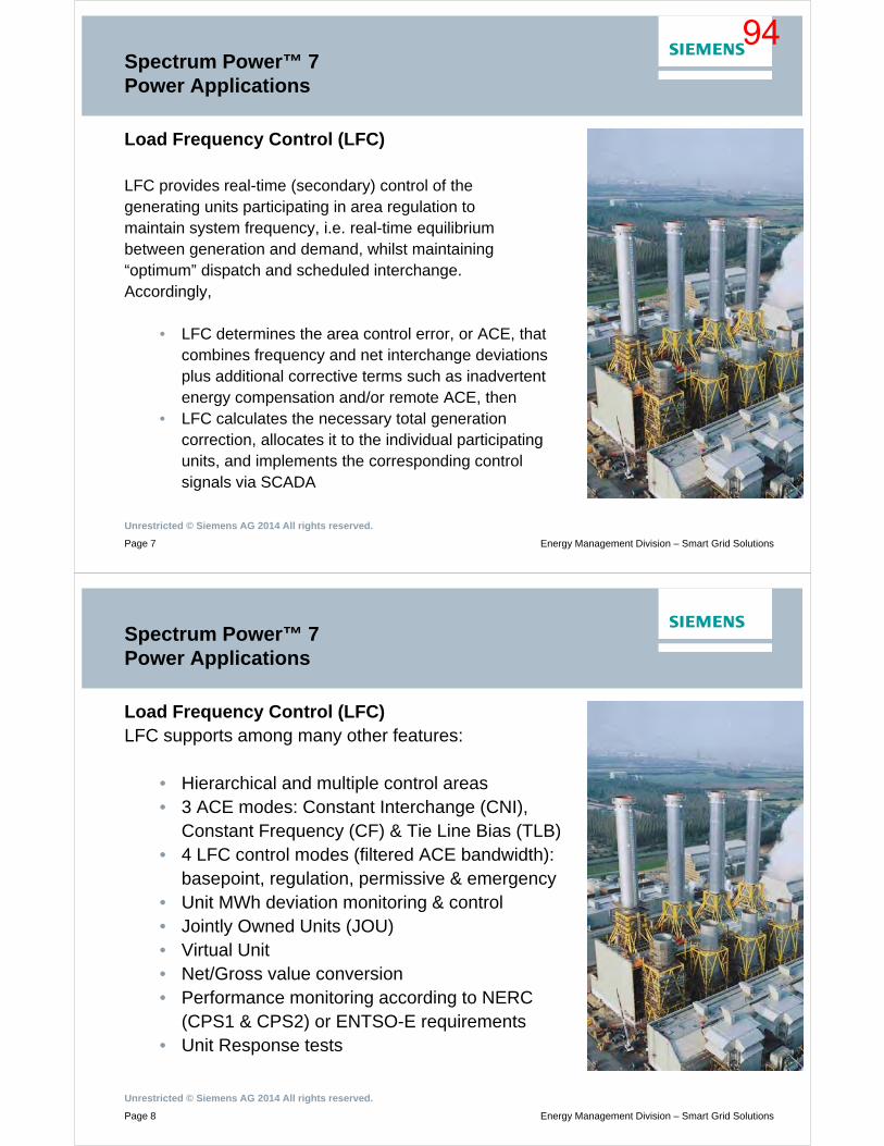
Unrestricted © Siemens AG 2014 All rights reserved.
Page 7 Energy Management Division – Smart Grid Solutions
Spectrum Power™ 7 Power Applications
Load Frequency Control (LFC)
LFC provides real-time (secondary) control of thegenerating units participating in area regulation tomaintain system frequency, i.e. real-time equilibriumbetween generation and demand, whilst maintaining“optimum” dispatch and scheduled interchange.Accordingly,
• LFC determines the area control error, or ACE, that combines frequency and net interchange deviations plus additional corrective terms such as inadvertent energy compensation and/or remote ACE, then
• LFC calculates the necessary total generation correction, allocates it to the individual participating units, and implements the corresponding control signals via SCADA
Unrestricted © Siemens AG 2014 All rights reserved.
Page 8 Energy Management Division – Smart Grid Solutions
Spectrum Power™ 7 Power Applications
Load Frequency Control (LFC)LFC supports among many other features:
• Hierarchical and multiple control areas• 3 ACE modes: Constant Interchange (CNI),
Constant Frequency (CF) & Tie Line Bias (TLB)• 4 LFC control modes (filtered ACE bandwidth):
basepoint, regulation, permissive & emergency• Unit MWh deviation monitoring & control• Jointly Owned Units (JOU)• Virtual Unit• Net/Gross value conversion• Performance monitoring according to NERC
(CPS1 & CPS2) or ENTSO-E requirements• Unit Response tests
94
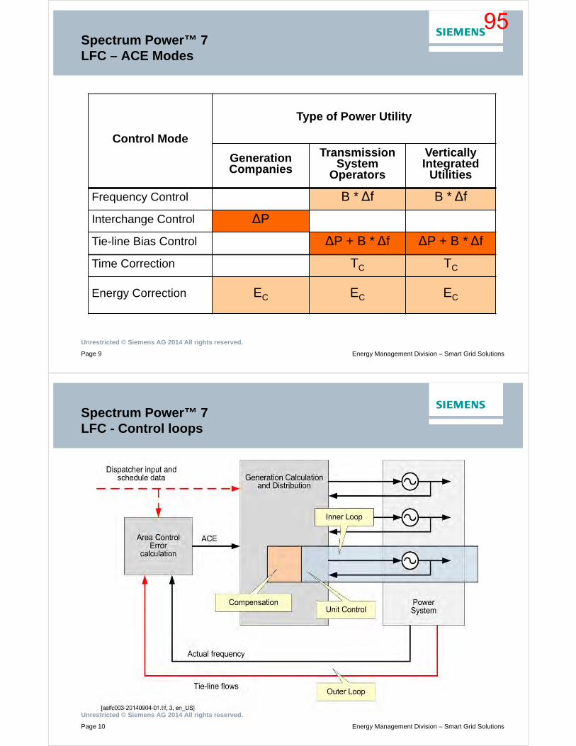
Unrestricted © Siemens AG 2014 All rights reserved.
Page 9 Energy Management Division – Smart Grid Solutions
Control Mode
Type of Power Utility
GenerationCompanies
TransmissionSystem
Operators
VerticallyIntegrated
Utilities
Frequency Control B * ∆f B * ∆f
Interchange Control ∆P
Tie-line Bias Control ∆P + B * ∆f ∆P + B * ∆f
Time Correction TC TC
Energy Correction EC EC EC
Spectrum Power™ 7 LFC – ACE Modes
Unrestricted © Siemens AG 2014 All rights reserved.
Page 10 Energy Management Division – Smart Grid Solutions
Spectrum Power™ 7 LFC - Control loops
95
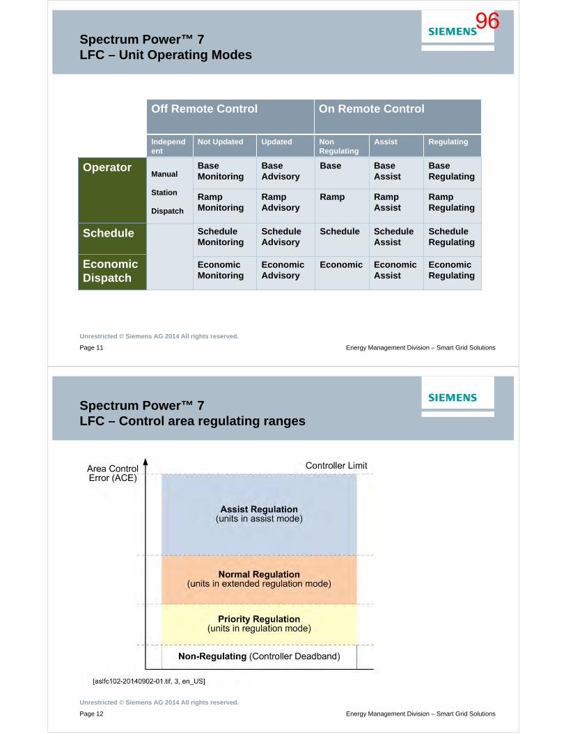
Unrestricted © Siemens AG 2014 All rights reserved.
Page 11 Energy Management Division – Smart Grid Solutions
Spectrum Power™ 7 LFC – Unit Operating Modes
Off Remote Control On Remote Control
Independent
Not Updated Updated NonRegulating
Assist Regulating
Manual
Station
Dispatch
Base Monitoring
Base Advisory
Base Base Assist
Base Regulating
Ramp Monitoring
Ramp Advisory
Ramp Ramp Assist
Ramp Regulating
Schedule Monitoring
Schedule Advisory
Schedule Schedule Assist
Schedule Regulating
Economic Monitoring
Economic Advisory
Economic Economic Assist
Economic Regulating
Operator
Schedule
Economic Dispatch
Unrestricted © Siemens AG 2014 All rights reserved.
Page 12 Energy Management Division – Smart Grid Solutions
Spectrum Power™ 7 LFC – Control area regulating ranges
96
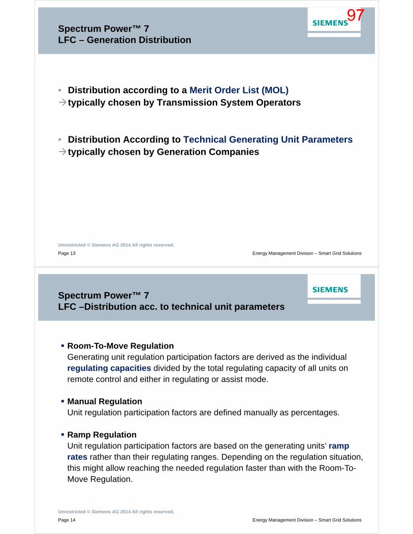
Unrestricted © Siemens AG 2014 All rights reserved.
Page 13 Energy Management Division – Smart Grid Solutions
Spectrum Power™ 7 LFC – Generation Distribution
• Distribution according to a Merit Order List (MOL)typically chosen by Transmission System Operators
• Distribution According to Technical Generating Unit Parameterstypically chosen by Generation Companies
Unrestricted © Siemens AG 2014 All rights reserved.
Page 14 Energy Management Division – Smart Grid Solutions
Room-To-Move RegulationGenerating unit regulation participation factors are derived as the individual regulating capacities divided by the total regulating capacity of all units on remote control and either in regulating or assist mode.
Manual RegulationUnit regulation participation factors are defined manually as percentages.
Ramp RegulationUnit regulation participation factors are based on the generating units’ ramp rates rather than their regulating ranges. Depending on the regulation situation, this might allow reaching the needed regulation faster than with the Room-To-Move Regulation.
Spectrum Power™ 7 LFC –Distribution acc. to technical unit parameters
97
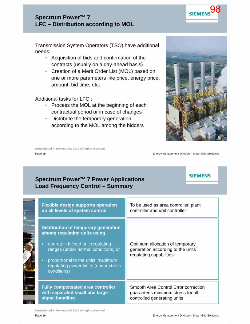
Unrestricted © Siemens AG 2014 All rights reserved.
Page 15 Energy Management Division – Smart Grid Solutions
Spectrum Power™ 7 LFC – Distribution according to MOL
Transmission System Operators (TSO) have additional needs:
• Acquisition of bids and confirmation of the contracts (usually on a day-ahead basis)
• Creation of a Merit Order List (MOL) based on one or more parameters like price, energy price, amount, bid time, etc.
Additional tasks for LFC :• Process the MOL at the beginning of each
contractual period or in case of changes• Distribute the temporary generation
according to the MOL among the bidders
Unrestricted © Siemens AG 2014 All rights reserved.
Page 16 Energy Management Division – Smart Grid Solutions
Spectrum Power™ 7 Power ApplicationsLoad Frequency Control – Summary
Flexible design supports operation on all levels of system control
To be used as area controller, plant controller and unit controller
Distribution of temporary generation among regulating units using
• operator-defined unit regulating ranges (under normal conditions) or
• proportional to the units’ maximum regulating power limits (under stress conditions)
Optimum allocation of temporary generation according to the units` regulating capabilities
Fully compensated area controller with separated small and large signal handling
Smooth Area Control Error correction guarantees minimum stress for all controlled generating units
98
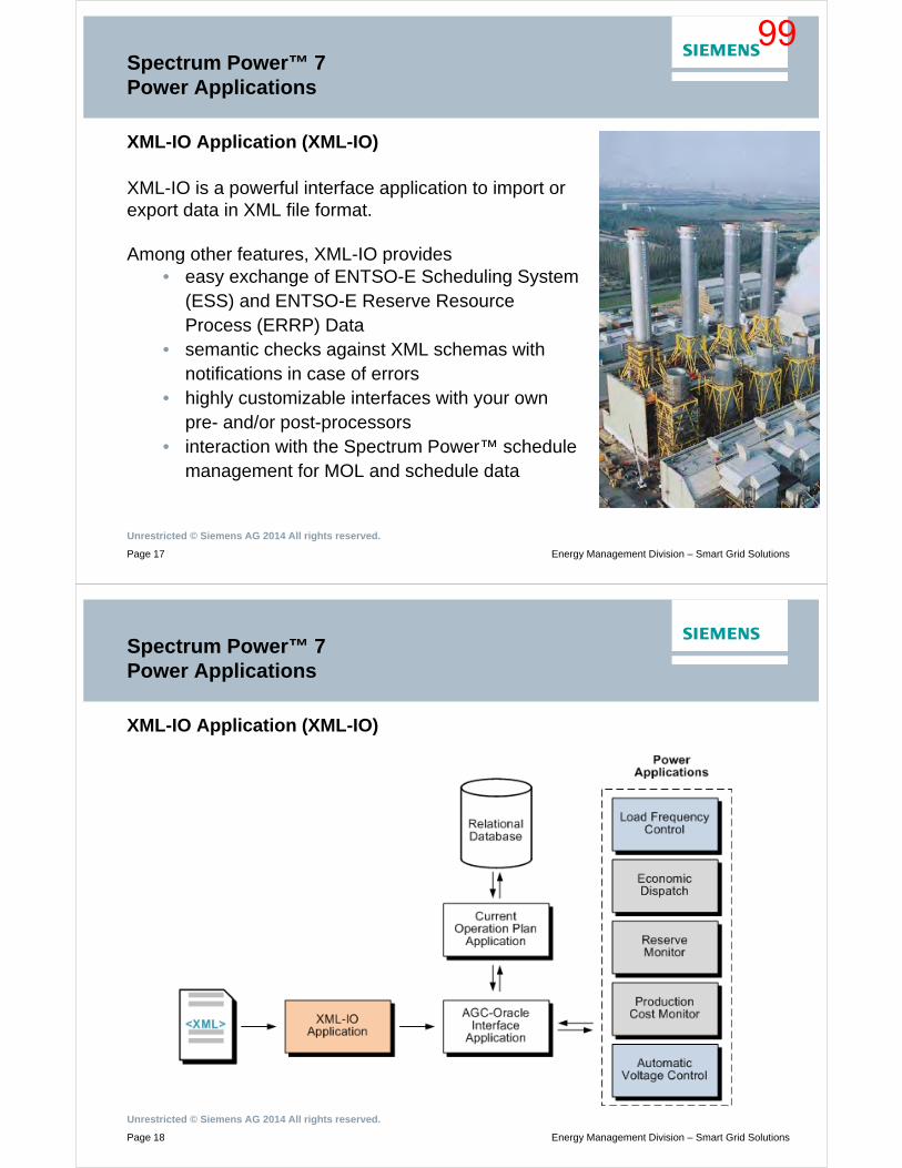
Unrestricted © Siemens AG 2014 All rights reserved.
Page 17 Energy Management Division – Smart Grid Solutions
Spectrum Power™ 7 Power Applications
XML-IO Application (XML-IO)
XML-IO is a powerful interface application to import or export data in XML file format.
Among other features, XML-IO provides• easy exchange of ENTSO-E Scheduling System
(ESS) and ENTSO-E Reserve Resource Process (ERRP) Data
• semantic checks against XML schemas with notifications in case of errors
• highly customizable interfaces with your own pre- and/or post-processors
• interaction with the Spectrum Power™ schedule management for MOL and schedule data
Unrestricted © Siemens AG 2014 All rights reserved.
Page 18 Energy Management Division – Smart Grid Solutions
Spectrum Power™ 7Power Applications
XML-IO Application (XML-IO)
99

Unrestricted © Siemens AG 2014 All rights reserved.
Page 19 Energy Management Division – Smart Grid Solutions
Spectrum Power™ 7XML-IO Application – Summary
Generic application architecture and configuration
Allows concurrent processing of multiple files and is suited for many use cases
Highly configurable interfacesAllow the creation of own pre- and post-processor scripts for checks or edits of the provided files
Compliance with the latest ESS and ERRP standards
Allows easy data exchange in standardized XML file formats with internal and external parties
Unrestricted © Siemens AG 2014 All rights reserved.
Page 20 Energy Management Division – Smart Grid Solutions
Spectrum PowerTM 7Power Applications – Economic Dispatch
Economic Dispatch (ED)ED allocates optimally the total generation requirement (sum ofbase point values + system regulation calculated by LFC)among participating generation units. This allocation eitherminimizes the total system production cost or maximizes thetotal system profit subject to
• Total generation requirement • Reserve (spinning) requirements• Plant and unit limits• Production cost characteristics
The solution is derived from an algorithm based on thenonlinear Dantzig/Wolfe decomposition principle.
ED is executed cyclically, on operator request or on LFCtrigger and can be executed either in normal mode or inanticipatory mode.
100
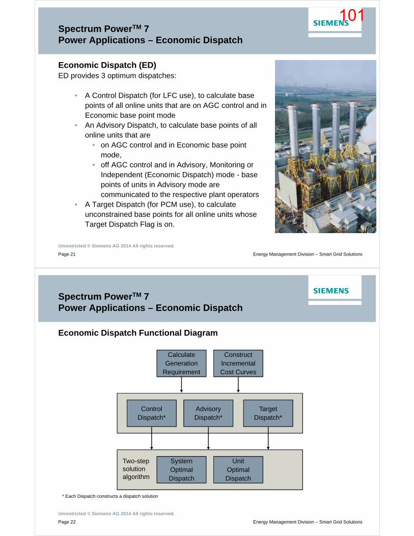
Unrestricted © Siemens AG 2014 All rights reserved.
Page 21 Energy Management Division – Smart Grid Solutions
Spectrum PowerTM 7Power Applications – Economic Dispatch
Economic Dispatch (ED)ED provides 3 optimum dispatches:
• A Control Dispatch (for LFC use), to calculate base points of all online units that are on AGC control and in Economic base point mode
• An Advisory Dispatch, to calculate base points of all online units that are
• on AGC control and in Economic base point mode,
• off AGC control and in Advisory, Monitoring or Independent (Economic Dispatch) mode - base points of units in Advisory mode are communicated to the respective plant operators
• A Target Dispatch (for PCM use), to calculate unconstrained base points for all online units whose Target Dispatch Flag is on.
Unrestricted © Siemens AG 2014 All rights reserved.
Page 22 Energy Management Division – Smart Grid Solutions
Spectrum PowerTM 7Power Applications – Economic Dispatch
Economic Dispatch Functional Diagram
* Each Dispatch constructs a dispatch solution
Control Dispatch*
Advisory Dispatch*
Target Dispatch*
System Optimal Dispatch
Unit Optimal Dispatch
Two-stepsolutionalgorithm
Calculate Generation
Requirement
Construct Incremental Cost Curves
101
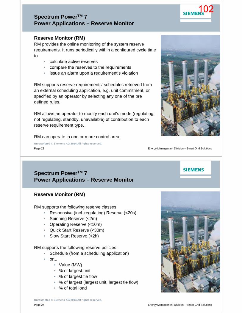
Unrestricted © Siemens AG 2014 All rights reserved.
Page 23 Energy Management Division – Smart Grid Solutions
Spectrum PowerTM 7Power Applications – Reserve Monitor
Reserve Monitor (RM)RM provides the online monitoring of the system reserverequirements. It runs periodically within a configured cycle timeto
• calculate active reserves• compare the reserves to the requirements• issue an alarm upon a requirement’s violation
RM supports reserve requirements’ schedules retrieved froman external scheduling application, e.g. unit commitment, orspecified by an operator by selecting any one of the predefined rules.
RM allows an operator to modify each unit’s mode (regulating,not regulating, standby, unavailable) of contribution to eachreserve requirement type.
RM can operate in one or more control area.
Unrestricted © Siemens AG 2014 All rights reserved.
Page 24 Energy Management Division – Smart Grid Solutions
Spectrum PowerTM 7Power Applications – Reserve Monitor
Reserve Monitor (RM)
RM supports the following reserve classes:• Responsive (incl. regulating) Reserve (<20s)• Spinning Reserve (<2m)• Operating Reserve (<10m)• Quick Start Reserve (<30m)• Slow Start Reserve (<2h)
RM supports the following reserve policies:• Schedule (from a scheduling application)• or...
• Value (MW)• % of largest unit• % of largest tie flow• % of largest (largest unit, largest tie flow)• % of total load
102

Unrestricted © Siemens AG 2014 All rights reserved.
Page 25 Energy Management Division – Smart Grid Solutions
Spectrum PowerTM 7Power Applications – Production Cost Monitor
Production Cost Monitor (PCM)
PCM provides the online monitoring of the actualproduction costs based on actual unit generationsagainst the optimal production costs based on ED’starget dispatch results. Whenever the actual costsexceed the target costs, PCM produces an alarm.
Cost calculations are made • per unit, plant and system, and • for current values, hourly averages and daily
integrals of the hourly average values.PCM provides also for the calculation of
• fuel consumption, including that of water, and• startup costs including number of daily startups,
etc.
Unrestricted © Siemens AG 2014 All rights reserved.
Page 26 Energy Management Division – Smart Grid Solutions
Spectrum PowerTM 7Content
• Overview
• Functions
• User Functions
• Summary
103

Unrestricted © Siemens AG 2014 All rights reserved.
Page 27 Energy Management Division – Smart Grid Solutions
Spectrum PowerTM 7Power Applications – New Modern User Interface
Unrestricted © Siemens AG 2014 All rights reserved.
Page 28 Energy Management Division – Smart Grid Solutions
Spectrum PowerTM 7Content
• Overview
• Functions
• User Functions
• Summary
104

Unrestricted © Siemens AG 2014 All rights reserved.
Page 29 Energy Management Division – Smart Grid Solutions
Spectrum Power™ 7 Power ApplicationsLoad Frequency Control – Summary
Various selections of area control modes can be combined:
• Frequency error correction• Time error correction• Net interchange error correction• Inadvertent energy correction
within the current period• Inadvertent energy correction
based on data calculated by the Energy Accounting application
Allows on demand selection of control modes by the operators depending on the current network requirements and contractual obligations
Anticipatory mode algorithmBest reduction of Area Control Error during steadily increasing and decreasing load situations
Unrestricted © Siemens AG 2014 All rights reserved.
Page 30 Energy Management Division – Smart Grid Solutions
Spectrum Power™ 7 Power Applications –Economic Dispatch Summary
Based on the principle of equalincremental costs (lambda dispatchalgorithm)
Very short calculation time allows economic real-time dispatch of the temporary generation
Handling of multiple fuels possible
Up to five fuel types per generating unit possible
Supports percentage based calculation of fuel mixtures
base fuel/top fuel handling
Cost savings in fuel cost and unit maintenance cost due to detailed modeling of the reality
Automatic consideration ofuneconomic regions (valve points)for both thermal and hydrogenerating units
Prevents units from being driven at power values where the throttling losses are a maximum, i.e. when a valve is nearly closed
105

Unrestricted © Siemens AG 2014 All rights reserved.
Page 31 Energy Management Division – Smart Grid Solutions
Spectrum Power™ 7 Power Applications –Reserve Monitor Summary
Supports up to 5 reserve classes and
various reserve calculation modules
for a wide range of reserve elements
Cost savings due to detailed modeling of the reality
Reserve policy for different
emergency situations like loss of
units or interchange
Suited both for generation and transmission companies
Allows different reserve policies for
working days, holidays and
weekends, and up to 5 special days
defined by certain dates
Reserve policy is highly adaptive to the network load on different days
Unrestricted © Siemens AG 2014 All rights reserved.
Page 32 Energy Management Division – Smart Grid Solutions
Spectrum Power™ 7 Power Applications –Reserve Monitor Summary
Highly configurable requirements
for reserve classes (MW values,
user-defined percentage of
biggest generating unit, user
defined percentage of biggest
interchange, user-defined
percentage of current system
load)
Allows fine tuning of required system reserve, thus helping to minimize the system operation and standby costs
106

Unrestricted © Siemens AG 2014 All rights reserved.
Page 33 Energy Management Division – Smart Grid Solutions
Spectrum Power™ 7 Power Applications –Production Cost Monitor Summary
Online monitoring of production
costs and fuel consumption
Real-time feedback on how close the system is operated to the economic optimum
Unrestricted © Siemens AG 2014 All rights reserved.
Page 34 Energy Management Division – Smart Grid Solutions
Spectrum Power™ 7 Power Applications
Thank You !
[email protected]@[email protected]
107

~
Annexe-5
108
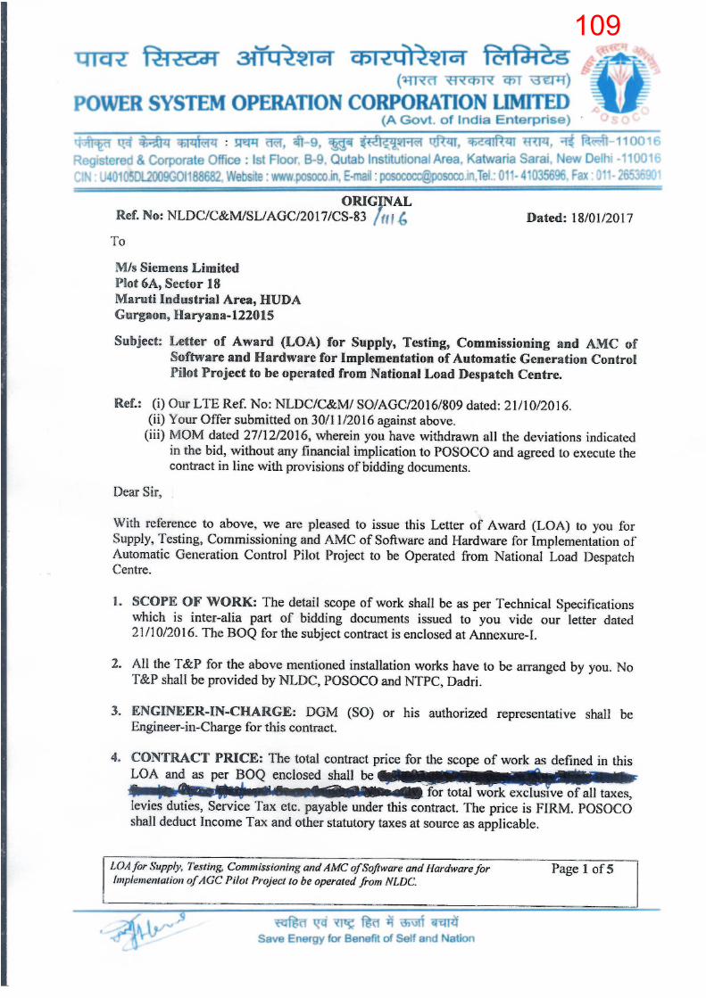
109

110

111
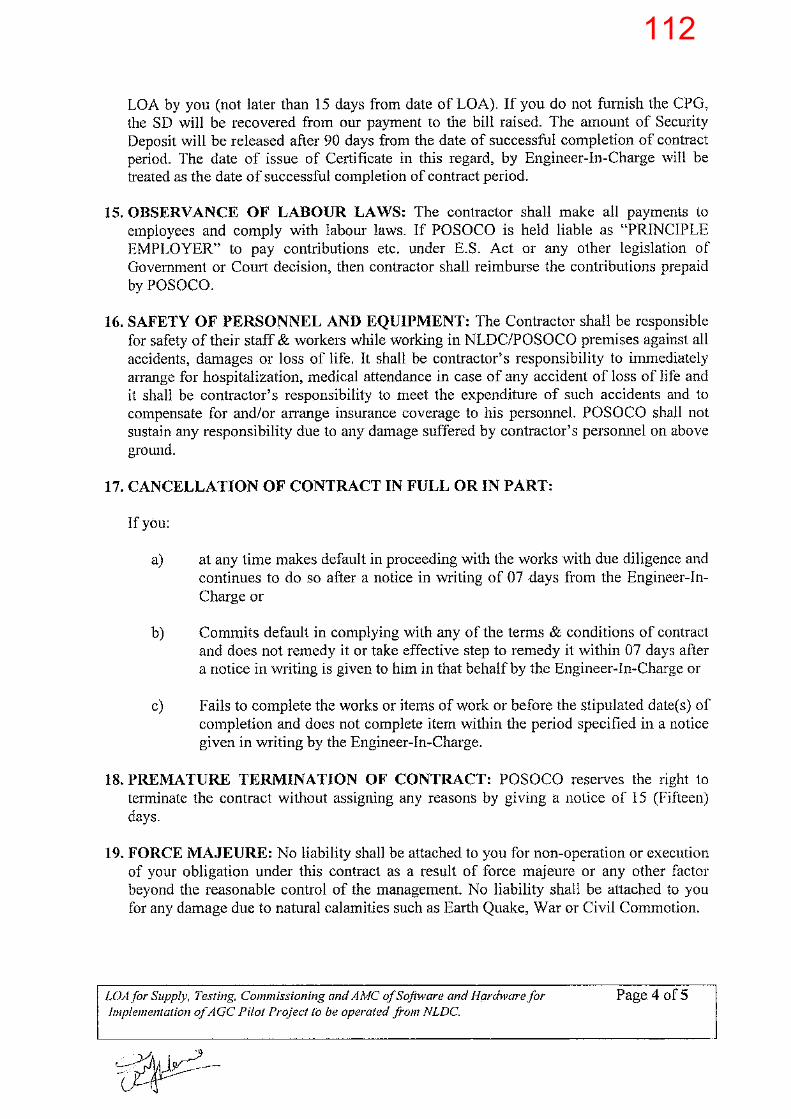
112
113

114

Automatic Generation Control (AGC)
First Pilot Project at NTPC Dadri
10th March 2017
115

Outline
• Commission’s orders on spinning reserves
• Frequency profile of different systems and India
• Primary Control
• Secondary control through Automatic Generation Control (AGC) – Details of pilot project by POSOCO and NTPC
– Further steps
• Commercial mechanism for plants under AGC
• Further directions required from Hon’ble Commission
2
116
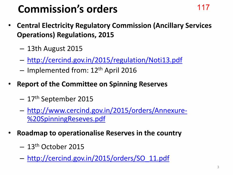
Commission’s orders
• Central Electricity Regulatory Commission (Ancillary Services Operations) Regulations, 2015
– 13th August 2015
– http://cercind.gov.in/2015/regulation/Noti13.pdf
– Implemented from: 12th April 2016
• Report of the Committee on Spinning Reserves
– 17th September 2015
– http://www.cercind.gov.in/2015/orders/Annexure-%20SpinningReseves.pdf
• Roadmap to operationalise Reserves in the country
– 13th October 2015
– http://cercind.gov.in/2015/orders/SO_11.pdf
3
117

Roadmap to operationalise Reserves in the country - Salient points
• Philosophy recommended to be adopted
– Operation at constant frequency target of 50.0 Hz
– with constant area interchange
• For AGC, power plants and Load Dispatch Centres (LDCs)
– necessary software and communication infrastructure
– Automated control signals from LDC to the generator
• AGC to be operationalized wef 1st April 2017
POSOCO awarded a pilot AGC project on 18th Jan 2017
4
118
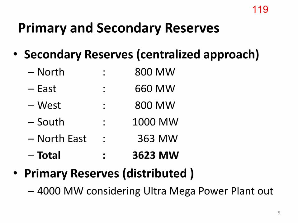
Primary and Secondary Reserves
• Secondary Reserves (centralized approach)
– North : 800 MW
– East : 660 MW
– West : 800 MW
– South : 1000 MW
– North East : 363 MW
– Total : 3623 MW
• Primary Reserves (distributed )
– 4000 MW considering Ultra Mega Power Plant out
5
119
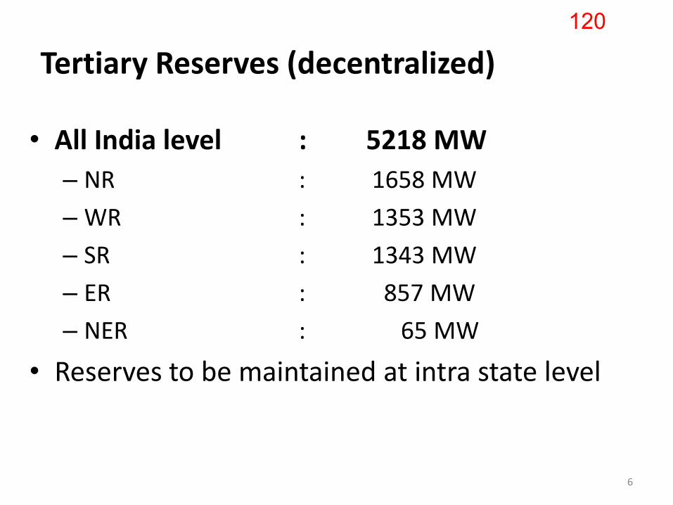
Tertiary Reserves (decentralized)
• All India level : 5218 MW
– NR : 1658 MW
– WR : 1353 MW
– SR : 1343 MW
– ER : 857 MW
– NER : 65 MW
• Reserves to be maintained at intra state level
6
120

Year: 2016 Source: Derived from http://fnetpublic.utk.edu/ 7
121

Frequency profile of Continental Europe
Narrow range of 49.96-50.04 Hz!!
Deterministic frequency deviations – root causes and proposals for potential solutions -------------------------------------------------------------------------------------------------- A joint EURELECTRIC – ENTSO-E response paper
8
122
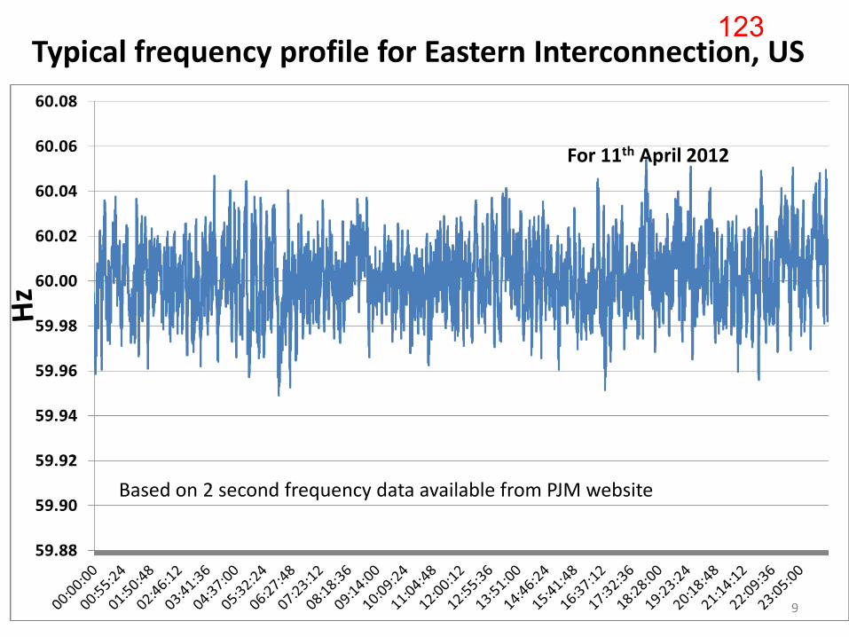
Typical frequency profile for Eastern Interconnection, US
For 11th April 2012
Based on 2 second frequency data available from PJM website
9
123
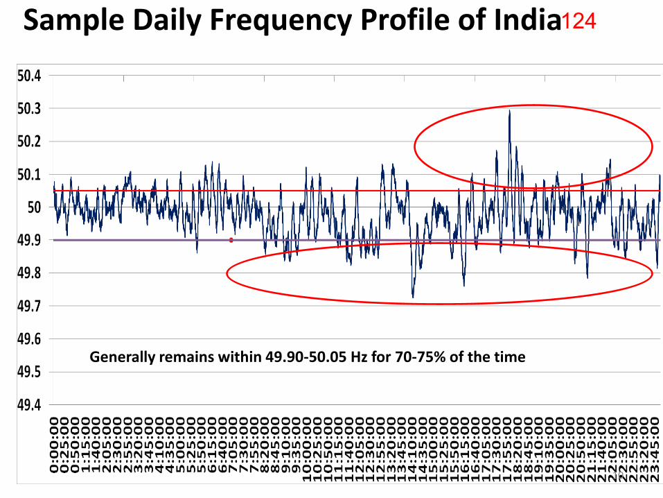
Sample Daily Frequency Profile of India
Generally remains within 49.90-50.05 Hz for 70-75% of the time
10
124

Frequency Profile 125
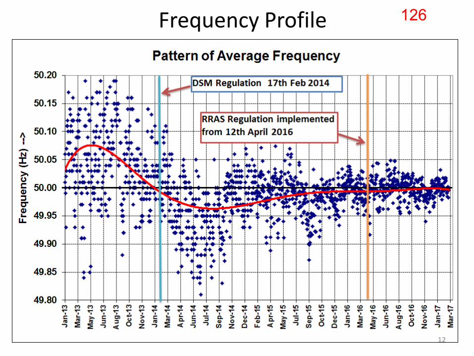
Frequency Profile
12
126
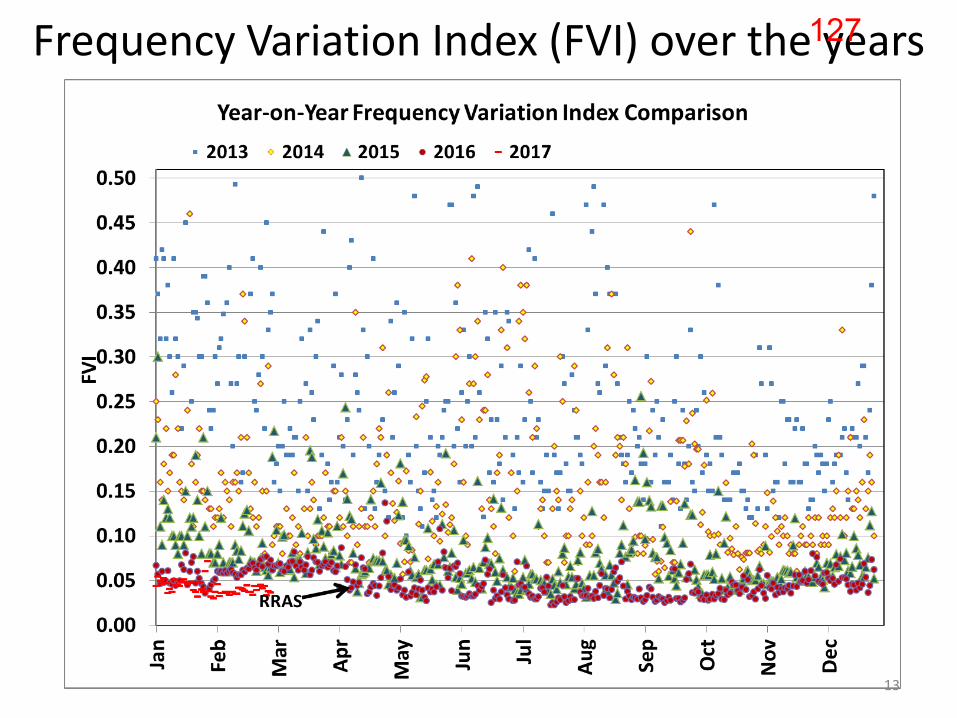
Frequency Variation Index (FVI) over the years
13
127
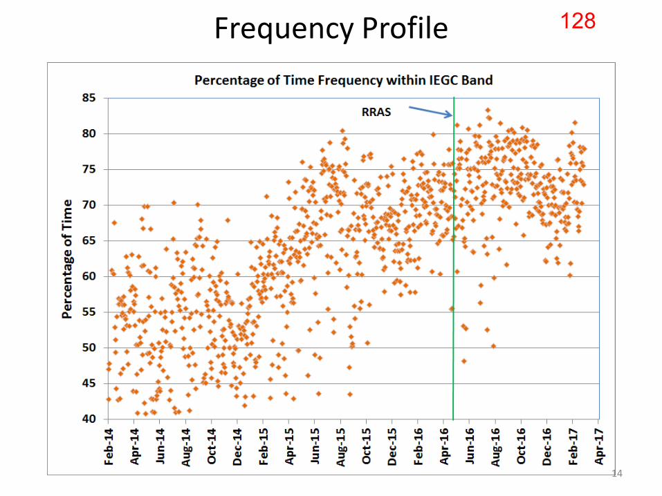
Frequency Profile
14
128
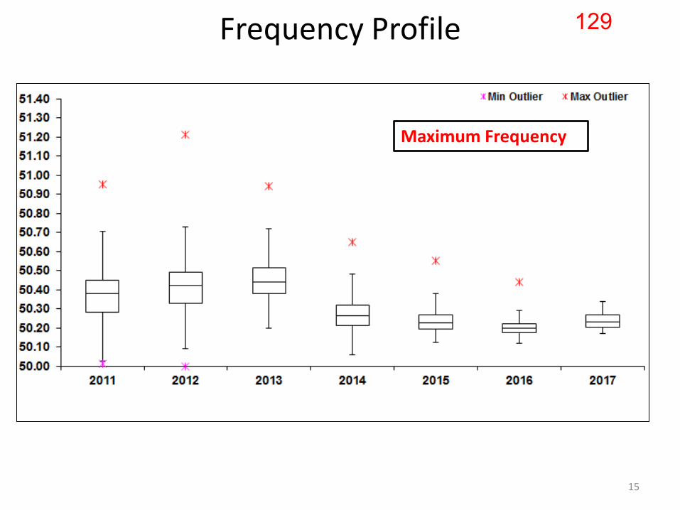
Frequency Profile
Maximum Frequency
15
129

Frequency Profile
Average Frequency ~ 50 Hz.
16
130
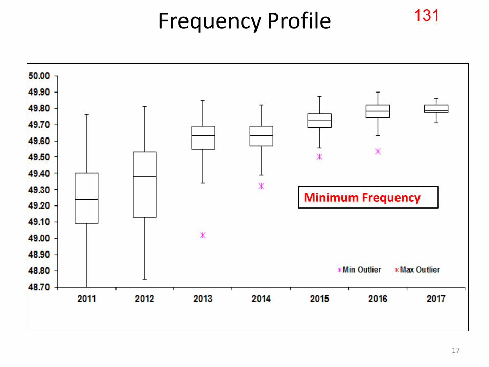
Minimum Frequency
Frequency Profile
17
131
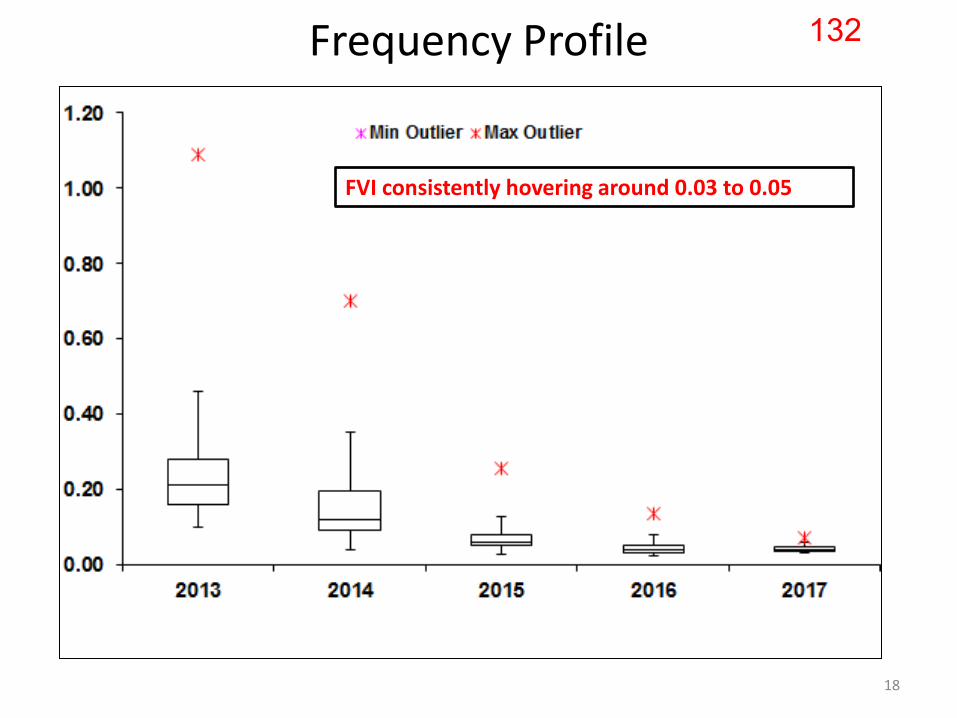
Frequency Profile
FVI consistently hovering around 0.03 to 0.05
18
132

Frequency as per global standards in India • Load and RE forecasting
– Decentralized at State level
• Unit commitment and Scheduling – Decentralized – Move from 15-minutes to 5-minute scheduling (SAMAST)
• Load following resources – Decentralized
• Fast/slow tertiary response – Centralized through Ancillary Services at ISTS level
• Secondary response – Automatic Generation Control (AGC) at regional level
• Primary control – Decentralized
19
133
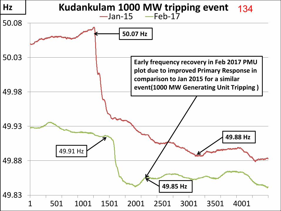
49.83
49.88
49.93
49.98
50.03
50.08
1 501 1001 1501 2001 2501 3001 3501 4001
Jan-15 Feb-17
Early frequency recovery in Feb 2017 PMU plot due to improved Primary Response in comparison to Jan 2015 for a similar event(1000 MW Generating Unit Tripping )
49.88 Hz
49.85 Hz
Hz
50.07 Hz
49.91 Hz
Kudankulam 1000 MW tripping event 134

• Frequency Response Characteristics (FRC) has increased from 6000 MW/Hz in early 2015 to over 9000 MW/Hz in Mar 2017
• Quarterly reports submitted to CERC for 39 events since Jan 2015
Commission’s orders have facilitated primary response order dated 13th Feb 2017 in petition 65/MP/2014 Target FRC of 15000 MW/Hz suggested along with testing
21
135

CERC Terms and Conditions of Tariff Regulations, 2014
“ the rate of return of a new project shall be reduced by 1% for such period as may be decided by the Commission, if the generating station or transmission system is found to be declared under commercial operation without commissioning of any of the Restricted Governor Mode Operation (RGMO)/ Free Governor Mode Operation (FGMO), data telemetry, communication system up to load dispatch centre or protection system:
as and when any of the above requirements are found lacking in a generating station based on the report submitted by the respective RLDC, RoE shall be reduced by 1% for the period for which the deficiency continues “
22
136
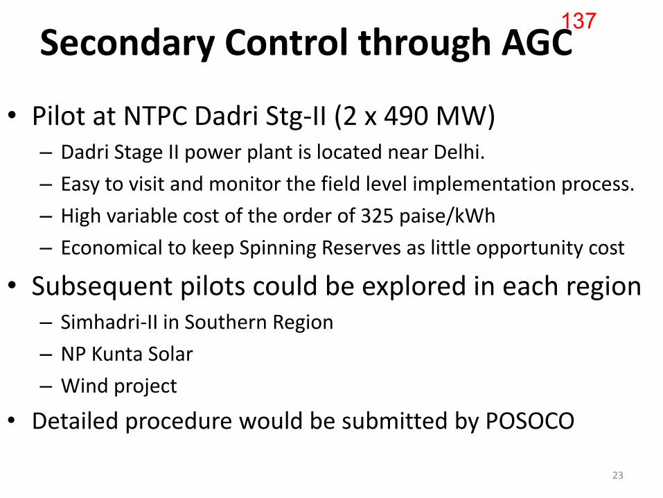
Secondary Control through AGC
• Pilot at NTPC Dadri Stg-II (2 x 490 MW) – Dadri Stage II power plant is located near Delhi.
– Easy to visit and monitor the field level implementation process.
– High variable cost of the order of 325 paise/kWh
– Economical to keep Spinning Reserves as little opportunity cost
• Subsequent pilots could be explored in each region – Simhadri-II in Southern Region
– NP Kunta Solar
– Wind project
• Detailed procedure would be submitted by POSOCO
23
137

Project progress • A team from POSOCO, POWERGRID and M/s Siemens
– visited NTPC Dadri on 6th May 2016 – to explore the ground level requirements with NTPC
• Execution of AGC pilot project as per technical specifications through limited tender – Invited bids on 21st October 2016 from the four SCADA vendors
• M/s ALSTOM • M/s OSI • M/s Siemens • M/s ABB
• Bids opened on 30th Nov 2016 • Letter of Award (LOA) issued to M/s Siemens on 18th Jan’17
and accepted by Siemens on 25th Jan ‘17
24
138

Technical Specifications
25
139
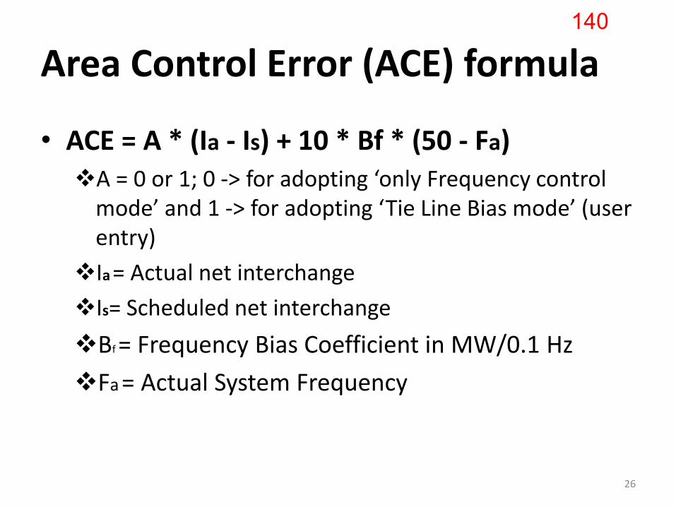
Area Control Error (ACE) formula
• ACE = A * (Ia - Is) + 10 * Bf * (50 - Fa) A = 0 or 1; 0 -> for adopting ‘only Frequency control
mode’ and 1 -> for adopting ‘Tie Line Bias mode’ (user entry)
Ia = Actual net interchange
Is= Scheduled net interchange
Bf = Frequency Bias Coefficient in MW/0.1 Hz
Fa = Actual System Frequency
26
140
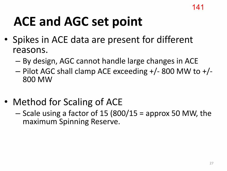
ACE and AGC set point • Spikes in ACE data are present for different
reasons. – By design, AGC cannot handle large changes in ACE – Pilot AGC shall clamp ACE exceeding +/- 800 MW to +/-
800 MW
• Method for Scaling of ACE – Scale using a factor of 15 (800/15 = approx 50 MW, the
maximum Spinning Reserve.
27
141
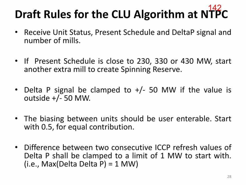
Draft Rules for the CLU Algorithm at NTPC
• Receive Unit Status, Present Schedule and DeltaP signal and number of mills.
• If Present Schedule is close to 230, 330 or 430 MW, start
another extra mill to create Spinning Reserve. • Delta P signal be clamped to +/- 50 MW if the value is
outside +/- 50 MW. • The biasing between units should be user enterable. Start
with 0.5, for equal contribution. • Difference between two consecutive ICCP refresh values of
Delta P shall be clamped to a limit of 1 MW to start with. (i.e., Max(Delta Delta P) = 1 MW) 28
142

Proposal for commercial settlement for AGC services offered by NTPC Dadri Stage-II
1. Factoring AGC signals while evaluating Deviations.
2. Compensate for the Extra Energy spent/saved
3. Incentivize for the ‘secondary regulation’ services
• CERC Order needed to facilitate all of the above
29
143
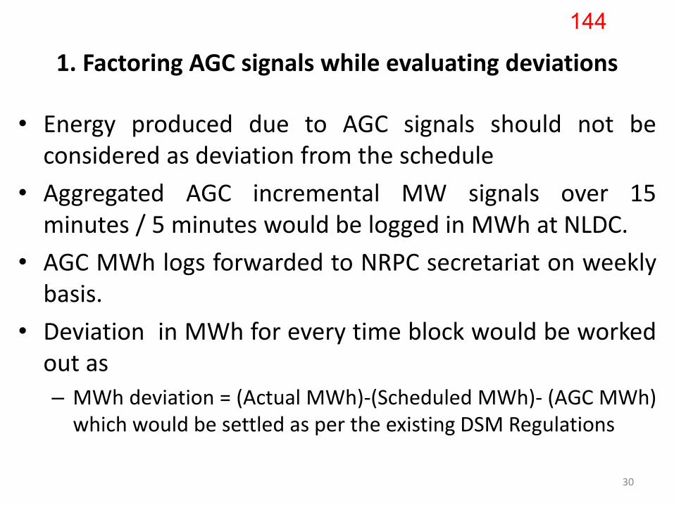
1. Factoring AGC signals while evaluating deviations
• Energy produced due to AGC signals should not be considered as deviation from the schedule
• Aggregated AGC incremental MW signals over 15 minutes / 5 minutes would be logged in MWh at NLDC.
• AGC MWh logs forwarded to NRPC secretariat on weekly basis.
• Deviation in MWh for every time block would be worked out as
– MWh deviation = (Actual MWh)-(Scheduled MWh)- (AGC MWh) which would be settled as per the existing DSM Regulations
30
144
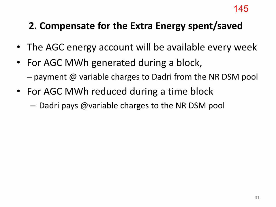
2. Compensate for the Extra Energy spent/saved
• The AGC energy account will be available every week
• For AGC MWh generated during a block,
– payment @ variable charges to Dadri from the NR DSM pool
• For AGC MWh reduced during a time block
– Dadri pays @variable charges to the NR DSM pool
31
145

3. Incentivize for the ‘secondary regulation’ services
• For AGC MWh in each time block (+ve or –ve)
– 50 paise/kWh mark up payable to NTPC Dadri from NR DSM pool
• Mark up of 50 paise/kWh similar to Ancillary Services (AS) framework of CERC.
• Periodic checks regarding compliance of plant to AGC signals
32
146
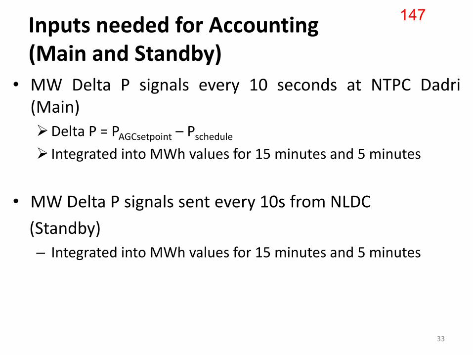
Inputs needed for Accounting (Main and Standby)
• MW Delta P signals every 10 seconds at NTPC Dadri (Main)
Delta P = PAGCsetpoint – Pschedule
Integrated into MWh values for 15 minutes and 5 minutes
• MW Delta P signals sent every 10s from NLDC
(Standby)
– Integrated into MWh values for 15 minutes and 5 minutes
33
147
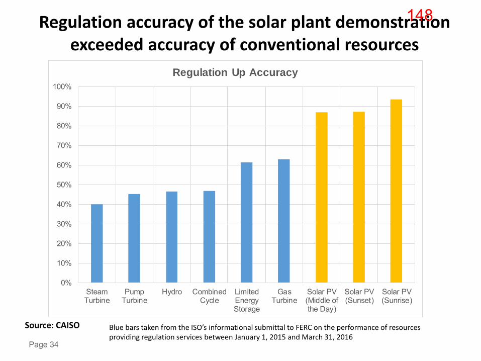
Regulation accuracy of the solar plant demonstration exceeded accuracy of conventional resources
Page 34
0%
10%
20%
30%
40%
50%
60%
70%
80%
90%
100%
SteamTurbine
PumpTurbine
Hydro CombinedCycle
LimitedEnergyStorage
GasTurbine
Solar PV(Middle ofthe Day)
Solar PV(Sunset)
Solar PV(Sunrise)
Regulation Up Accuracy
Blue bars taken from the ISO’s informational submittal to FERC on the performance of resources providing regulation services between January 1, 2015 and March 31, 2016
Source: CAISO
148

CERC approval is needed on the following • Go ahead for the pilot project for NTPC Dadri Stage-II (2 x 490 MW) to
receive AGC signals from NLDC and regulate to the extent of 50 MW up/down to start with and with provision to go up later.
• Deviation Settlement Mechanism (DSM) for Dadri Stage-II under AGC – Factoring AGC signals while working out deviations from the schedule
• Incentivize NTPC Dadri stg-II for the AGC services – 50 paise/kWh mark up similar to Ancillary Services framework
• Facilitate NRLDC to earmark 50 MW up/down reserves at NTPC Dadri Stage-II on days when full generation is requisitioned or schedule is at technical minimum
• Take up other pilot projects including wind and solar
35
149

Thank you
36
150

151

152
153