zoneflow engineering, installation, and maintenance manual · 4 spring air systems zoneflow...
TRANSCRIPT

Zoneflow Engineering, Installation, and Maintenance Manual
___________________________ Spring Air Systems Inc., Oakville, Ontario
Phone (905) 338-2999, Fax (905) 338-0179, [email protected] www.springairsystems.com

Zoneflow Engineering, Installation, and
Maintenance Manual
Introduction 1 What is a ZM Zoneflow? 1 ZM Zoneflow Operation 2 ZM Zoneflow for automatic air balancing 2 ZM Zoneflow for demand ventilation: Truflow Zoneflow panels 4 Truflow Zoneflow System Design 5 Truflow Zoneflow One (1) kitchen panel 5 Truflow Zoneflow Two (2) kitchen panel 8 Zone Flow Dampers and Thermal Start 11 ZM Zoneflow J-Box Wiring Schematic 12 ZM Zoneflow Spring Air Hood Section View 13 Top View three (3) ZM Zoneflow damper positions 14 What is a ZH Zoneflow? 15 Zoneflow Dimensions 18 Zoneflow Installation 20 Zoneflow Maintenance 22 Schedule for Inspection 22 Cleaning 24 Sample Specification 26

1 Spring Air Systems Zoneflow Engineering Manual 2013
Zoneflow Engineering, Installation,
and Maintenance Manual
Introduction The spring Air System Zoneflow is designed to be
installed in a commercial kitchen NFPA-96 central
exhaust fan duct system up stream of each hood to
automatically or manually modulate and/or balance
the exhaust air volume between the multiple hoods
connected to the common fan.
The Zoneflow is available in two types. ZM
Zoneflow with automatic modulating control
damper and ZH Zoneflow with manually adjustable
control damper.
Picture of ZM Vertical Zoneflow
Figure 1
What is a ZM Zoneflow?
The ZM Zoneflow is a UL/ULC listed balancing
damper designed for a Commercial Kitchen NFPA-
96 grease duct. The ZM Zoneflow can be supplied
loose to be welded into the kitchen grease duct
between the hood and exhaust fan or welded
directly to the exhaust duct collar of any Spring Air
System hood. The ZM Zoneflow provides
automatic modulation of the commercial kitchen
hood exhaust volume.
Dimensional Isometric of Horizontal ZM Zoneflow
Figure 2

2 Spring Air Systems Zoneflow Engineering Manual 2014
The ZM Zoneflow Description:
PHOTO SIDE VIEW
ZM Zoneflow 10” wide duct collar
Figure 3
The ZM Zoneflow is 12” deep in the direct of exhaust air flow and matches the length and width
dimensions of the hood exhaust duct collar. The outside casing is constructed of 16 GA continuously
welded cold rolled steel. The inlet and outlet of the ZM Zoneflow has a 1” perimeter flange for welding
to the NFPA-96 exhaust duct or the kitchen exhaust hood duct collar. The ZM Zoneflow assembly
includes a removable access door on the side of the ZM Zoneflow duct section. The access door is made
of 16 GA carbon steel and bolted to the ZM Zoneflow duct section and sealed with high temperature
gaskets. The access door is removable for inspection and damper and interior duct. Mounted on the
access door is a modulating motor U bolted to the internal control damper shaft. The modulating motor is
provided with a protective, painted, steel shield. The modulating motor is factory wired to a J-Box also
mounted on the access door. Power and control signals are provided through a CAT5 plug on the J-box.
The modulating motor requires 24VDC or 24VAC power and a 4-20 milliamp control signal.
ZM Zoneflow Operation A. ZM Zoneflow for automatic air balancing: Field balancing a commercial kitchen exhaust system is very
difficult when multiple hoods are connected to a single central
exhaust fan. In the schematic below the first hood closest to the
fan will exhaust too much air and the last hood in the system
typically will be starved for exhaust air. The ZM Zoneflow
provides a simple solution to automatically balance each hood
in the central single fan exhaust system. The ZM Zoneflow is
installed in each hood exhaust duct collar.
ZM Zoneflow with damper shield and
CAT5 J-Box
Figure 4

3 Spring Air Systems Zoneflow Engineering Manual 2014
ZM Zoneflow, Hood, Fan and Ductwork Schematic
Figure 3
The Duct and Hood Schematic shown above is a central exhaust fan with four commercial kitchen hoods.
Exhaust hood #4 closest to the fan would have too much exhaust air while exhaust hood #1 furthest away
from the central fan would be starved for exhaust air. By proportionally closing down ZM Zoneflow #4,
#3, and #2, the correct amount of exhaust air is provided to hood #1.
The ZM Zoneflow control damper motor requires 24VDC power and a 4-20milliamp control signal. A 4
milliamps signal drives the control damper to the lowest position, while a 20 milliamp signal opens the
control damper 100%. Modulating each ZM Zoneflow damper will set the proper air flow to each hood
connected to the central exhaust fan.
A 4-20milliamp signal is sent to each ZM Zoneflow installed in each hood duct collar from a Spring Air
Systems RPD-P11-ZM panel. The signal is modulated to position the control damper to provide the
correct amount of CFM (l/s) for each hood.
The ZM Zoneflow in hood #4 closest to the central fan receives a 6 milliamp signal to close the control
damper to 35% to provide the design CFM. The ZM Zoneflow in hood #1 furthest from the central fan is
receiving a 20 milliamp signal to open the control damper to 100% to provide the design CFM. Each ZM
Zoneflow is adjusted accordingly to provide the exact exhaust required for each hood.
The Spring Air System RPD-P11-ZM Zoneflow control panel below makes ZM Zoneflow setup even
easier. The RPD-P11-ZM provides an adjustable 4-20milliamp signal for each ZM Zoneflow. In
addition, the RPD-P11-ZM is a complete control system for the commercial kitchen operation. The panel
controls all aspects of the kitchen ventilation system. Each ZM Zoneflow damper position is adjusted by
rotating a dial inside the panel at start-up. In addition to controlling the ZM Zoneflow the panel
interlocks to all other components required to operate a commercial kitchen operation.

4 Spring Air Systems Zoneflow Engineering Manual 2014
RPD-11-ZM Electrical schematic for four (4) hoods with ZM Zoneflow,
And common central exhaust fan
Figure 4
B. ZM Zoneflow for demand ventilation: TRUFLOW ZONEFLOW
The average commercial kitchen exhaust system operates 12 to 18 hours per day. Today’s kitchen
systems exhaust at 100% capacity whenever they are turned on regardless of the number of appliances or
amount of cooking going on under the hood. The cook will arrive at 7:00 a.m. in the morning and switch
the system on for the day. The system is not shut off until the last person leaves the kitchen at the end of
the day. The reality is that the amount of actual high capacity cooking is a very small part of the total
operating day. Unfortunately, the exhaust and the supply (which heats and cools the fresh air to replace
the exhaust from the kitchen) operates continuously at full volume throughout the day.
The Truflow-Zoneflow system regulates the amount of air
exhausted from the kitchen to match the amount of cooking.
The Truflow Zoneflow is designed for central exhaust fan
systems with multiple hoods connected. As more appliances
under each hood are used the total exhaust and supply volume
increases, as fewer appliances under each hood are used the
total exhaust and supply volume decreases.
The Truflow-Zoneflow commercial kitchen variable
exhaust/supply control has been designed to change kitchen
exhaust forever. Truflow-Zoneflow will automatically reduce
the exhaust and supply air into the kitchen whenever
appliances are not used at full capacity. When the appliances
are not used and the heat is turned down or off the Truflow-
Zoneflow automatically senses this reduction and decreases
the amount of exhaust and supply to match exactly what’s
Truflow Zoneflow Touchscreen Panel
Figure 5

5 Spring Air Systems Zoneflow Engineering Manual 2014
happening under each exhaust hood. The Truflow-Zoneflow hood duct collar mounted J-Couple monitors
the exhaust temperature, which fluctuates based on the amount of appliances operating under the exhaust
hood. As the amount of cooking increases the exhaust duct temperature rises and reaches an equilibrium
temperature. The current equilibrium temperature is affected by many variables.
Total exhaust volume
BTU rating of each appliance
Total Volume of makeup
Temperature of Makeup air
Where the makeup air is introduced back into the kitchen
Type of hood over the appliance
The Truflow-Zoneflow automatically modulates the exhaust and supply to suit the actual cooking
operation at any given time during the cooking day. When the hood duct collar mounted J-couple senses
a temperature rise a signal is sent to the ZM Zoneflow to open the control damper to allow more exhaust
and/or supply variable speed drive to increase the frequency of the motor to provide more exhaust and
supply air.
Truflow Zoneflow System Design
The Truflow Zoneflow is available for one (1) kitchen (one central exhaust fan) and two (2) kitchen (two
central exhaust fans) arrangements.
One (1) kitchen panel: Panel is interlocked to one central exhaust fan and/or one supply fan with up to
(12) twelve hoods with ZM Zoneflow.
Zoneflow Truflow CAT5 and J-Cable
Schematic

6 Spring Air Systems Zoneflow Engineering Manual 2014
Figure 6
The Truflow Zoneflow schematic above outlines field installed CAT5 and J-Cable wiring to each
component of a One Kitchen (One exhaust fan and one supply fan) Truflow Zoneflow panel. The
schematic shows one exhaust fan drive and one supply fan drive, four hood exhaust duct collars with J-
Couples and Zoneflow Dampers. The drives will be modulated based on the temperature within the hood
duct collars.
Zoneflow Truflow 120V and 24V control wiring schematic
Figure 7
The Truflow Zoneflow schematic above indicates
the 24V and 120V input and output control wiring
required for the One Kitchen central exhaust fan
system. The exhaust and supply fan operation are
both controlled from this panel.
Top of Truflow Zoneflow Hub Panel
Figure 8

7 Spring Air Systems Zoneflow Engineering Manual 2014
Zoneflow Truflow power wiring
Figure 9
Zoneflow Truflow power wiring to Truflow Zoneflow Touchscreen panel
Figure 10

8 Spring Air Systems Zoneflow Engineering Manual 2014
The Truflow Zoneflow wiring schematic above shows all power wiring required to each component in a
One Kitchen commercial kitchen exhaust system.
Two (2) kitchen panels: Panels are interlocked to two central exhaust fan, one or two supply fan and up
to 12 ZM Zoneflow. The two (2) exhaust fans operate independently.
Zoneflow Truflow CAT5 and J-Cable wiring schematic for 6 –
Zoneflow, hoods and two (2) central fan
Figure 11
The Truflow Zoneflow schematic above outlines field installed CAT5 and J-Cable wiring to the
components of a Two Kitchen System with two central exhaust fans and one common supply fan. The
schematic shows one exhaust fan drive and one supply fan drive, four exhaust duct collars with J-Couples
and Zoneflow dampers. The drives will be modulated based on the temperature within the hood duct
collars.

9 Spring Air Systems Zoneflow Engineering Manual 2014
Zoneflow Truflow 120V and 24V control wiring schematic for
6 – Zoneflow, hoods and two(2) central fan
Figure 12
The Truflow Zoneflow schematic above indicates the 24V and 120V input and output control wiring
required for the Two Kitchen System. The exhaust and supply fan operation are both controlled form this
panel.

10 Spring Air Systems Zoneflow Engineering Manual 2014
Zoneflow Truflow Power wiring schematic for 6-Zoneflow, hoods and two (2) central fans
Figure 13
Zoneflow Truflow Touchscreen for 6 –Zoneflow, hoods and two (2) central fans
Figure 14
The Truflow Zoneflow wiring schematic above shows all power wiring required to each component in a
Two Kitchen commercial kitchen exhaust system.

11 Spring Air Systems Zoneflow Engineering Manual 2014
Zone Flow Dampers and Thermal Start
When Zone Flow dampers are used, the thermal start function of the system needs to be set up for each
individual hood damper. This is done by accessing the setup screen of the system. Touching the SET
POINTS icon activates a pop-up screen for the Zone Flow dampers.
Each damper has to be set to activate the thermal start feature for each Zone Flow damper. By touching
the small blank rectangle beside the larger boxes all dampers are selected. See Fig 2. Descriptions should
be added in the new Labels boxes beside each damper to identify the individual Zone Flow dampers.
The first box will default to a value of 70. These values should be set to the same value as the SV value of
the corresponding PXR temperature sensor. The Thermal Start is triggered based on the sensed
temperature against a scaled alarm from the SV value. Any hood can trigger the Thermal Start/AUTO
Start. The Thermal Start will be active for a maximum of 4 hours once triggered. It can be reset only by
selecting the system ON from the dashboard.
Figure 1
Figure 2 Figure 3

12 Spring Air Systems Zoneflow Engineering Manual 2014
ZM Zoneflow J-Box Wiring Schematic
The Zoneflow is 24VDC power and signal is
supplied through a CAT5 connector on the
Zoneflow J-Box. The CAT5 connector pin-
out and wire color coding is show in
Zoneflow J-Box wiring schematic. The J-
Box has an internal 500 ohm resistor and is
wired directly to the damper motor. The
signal supplied is 4-20milliamp to drive the
damper motor.
ZM Zoneflow J-Box internal wiring
and CAT5 Pin-Out
Figure 15
ZM Zoneflow Spring Air Hood Section View
Section view of FDBMB-ZM hood with vertical ZM Zoneflow
damper mounted on duct collar
Figure 16
The section view above shows a Spring Air Systems Dynaflow FDBMB with a Zoneflow mounted
directly to the duct collar. The duct collar is at the back of the hood and the Zoneflow extends 15” above
the roof of the hood requiring a building door width of at least 39” for passage into the building.
13 Spring Air Systems Zoneflow Engineering Manual 2014
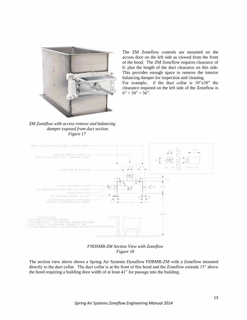
The ZM Zoneflow controls are mounted on the
access door on the left side as viewed from the front
of the hood. The ZM Zoneflow requires clearance of
6: plus the length of the duct clearance on this side.
This provides enough space to remove the interior
balancing damper for inspection and cleaning.
For example, if the duct collar is 10”x30” the
clearance required on the left side of the Zoneflow is
6” + 30” = 36”.
ZM Zoneflow with access remove and balancing
damper exposed from duct section.
Figure 17
FNDSMB-ZM Section View with Zoneflow
Figure 18
The section view above shows a Spring Air Systems Dynaflow FDBMB-ZM with a Zoneflow mounted
directly to the duct collar. The duct collar is at the front of this hood and the Zoneflow extends 15” above
the hood requiring a building door width of at least 41” for passage into the building.

14 Spring Air Systems Zoneflow Engineering Manual 2014
DDBFMP-ZM Revlow section view of with vertical ZM Zoneflow damper
Figure 19
MAXIMUM PARTIAL MAXIMUM
OPEN OPEN CLOSED
Top View of ZM Zoneflow in various damper positions
Figure 20

15 Spring Air Systems Zoneflow Engineering Manual 2014
What is a ZH Zoneflow?
The ZH Zoneflow is a UL/ULC listed manual
balancing damper designed for a NFPA-96 grease
duct. The ZH Zoneflow can be supplied loose to
be welded into the grease duct between the hood
and exhaust fan or welded directly to the exhaust
duct collar of any Spring Air Systems hood. The
ZH Zoneflow damper position is manually adjusted
to balance a series of individual hoods connected to
one exhaust fan.
ZH Zoneflow Isometric
Figure 21
The ZH Zoneflow Description:
The ZH Zoneflow is 12” deep in the direction of exhaust air flow and matches the length and width
dimensions of the hood exhaust duct collar. The outside casing is constructed of 16 GA. Continuously
welded cold rolled steel. The inlet and outlet of the ZM Zoneflow has a 1” perimeter flange for welding
to the NFPA-96 exhaust duct or the
kitchen exhaust hood duct collar.
The ZH Zoneflow assembly
includes a removable access door
on the side of the ZH Zoneflow
duct section. The access door is
made of 16 GA carbon steel and
bolted to the ZM Zoneflow duct
section and sealed with high
temperature gasket. The access
door is removable for inspection
and damper and interior duct.
Mounted on the access door is a
locking quadrant, U bolted to the
internal control damper shaft.
ZH Zoneflow Dimensions
Figure 22

16 Spring Air Systems Zoneflow Engineering Manual 2014
ZH Zoneflow Damper Adjustment
Figure 23
Adjusting the locking quadrant: The ZH Zoneflow is factory shipped set in the minimum position.
Unscrew the wing-nut on the locking quadrant. Slight the wing-nut and shaft along the opening in the
quadrant to the damper position required. Once in position, tighten the wing-nut to lock damper in
position. The top position is the maximum open position.
ZH Zoneflow, Hood, Fan and Ductwork Schematic
Figure 24
The Duct and Hood Schematic shown above is a central exhaust fan with four commercial kitchen hoods.
Each hood has a ZH Zoneflow on each hood. The hood #4 closest to the fan would have much exhaust
air while exhaust hood #1 furthest away from the central fan would be starved for exhaust air. By
manually adjusting the locking quadrant on the ZH Zoneflow #4, #3 and #2, the correct amount of
exhaust air is provided at each hood.

17 Spring Air Systems Zoneflow Engineering Manual 2014
Typical ZH Zoneflow Double Row Filter Hood Schematic
Figure 25
The schematic above shows a FNDB-ZH Zoneflow hood section view. The ZH Zoneflow is attached
directly to the island filter hood. The hood is split in two sections for shipping.
The ZH Zoneflow pictured to the left has the access door and
locking quadrant removed and the damper is partial removed
from the steel duct housing. Note the high temperature gasket
around the access door flange.
ZH Zoneflow with access door removed
Figure 26

18 Spring Air Systems Zoneflow Engineering Manual 2014
Zoneflow Dimensions The height (in the direction of air flow) of all ZH and ZM Zoneflow dampers is 12” (305mm). The width
and length match the width and length of the Spring Air Systems hood exhaust duct collar. The two
charts below indicated width and lengths of all exhaust duct collars. Chart No. 1 is for all Review hood
exhaust duct collars and Chart No.2 is for all other hood exhaust collars.
RevLow Exhaust Volume Vs Zoneflow Duct Size
Exhaust
Volume Duct Collar Size Exhaust
Volume
Duct Collar Size
CFM l/s W x L
in x in
W x L
mm x mm CFM l/s W x L
in x in
W x L
mm x mm 450 212 10 x 4 254 x 102 3500 1652 10 x 33.5 254 x 851
500 236 10 x 4.5 254 x 114 3625 1711 10 x 34.5 254 x 876
625 295 10 x 6.0 254 x 152 3750 1770 10 x 36.0 254 x 914
750 354 10 x 7.0 254 x 178 3875 1829 10 x 37.0 254 x 940
875 413 10 x 8.0 254 x 203 4000 1888 14 x 27.0 356 x 686
1000 472 10 x 9.5 254 x 241 4125 1947 14 x 28.0 356 x 711
1125 531 10 x 10.5 254 x 267 4250 2006 14 x 29.0 356 x 737
1250 590 10 x 12.0 254 x 305 4375 2065 14 x 30.0 356 x 762
1375 649 10 x 13.0 254 x 330 4500 2124 14 x 30.5 356 x 775
1500 708 10 x 14.0 254 x 356 4625 2183 14 x 31.5 356 x 800
1625 767 10 x 15.5 254 x 394 4750 2242 14 x 32.5 356 x 826
1750 826 10 x 16.5 254 x 419 4875 2301 14 x 33.0 356 x 838
1875 885 10 x 18.0 254 x 457 5000 2360 14 x 34.0 356 x 864
2000 944 10 x 19.0 254 x 483 5125 2419 14 x 35.0 356 x 889
2125 1003 10 x 20.0 254 x 508 5250 2475 14 x 36.0 356 x 914
2250 1062 10 x 21.5 254 x 546 5375 2537 14 x 36.5 356 x 927
2375 1121 10 x 22.5 254 x 572 5500 2596 14 x 37.5 356 x 953
2500 1180 10 x 24.0 254 x 610 5625 2655 14 x 38.5 356 x 978
2625 1239 10 x 25.0 254 x 635 5750 2714 14 x 39.0 356 x 991
2750 1298 10 x 26.0 254 x 660 5875 2773 14 x 40.0 356 x 1016
2875 1357 10 x 27.0 254 x 699 6000 2832 14 x 41.0 356 x 1041
3000 1416 10 x 28.5 254 x 724 6125 2891 14 x 42.0 356 x 1067
3125 1475 10 x 30.0 254 x 762 6250 2950 14 x 42.5 356 x 1080
3250 1534 10 x 31.0 254 x 787 6375 3008 16 x 38.0 406 x 965
3375 1593 10 x 32.0 254 x 813 6500 3067 16 x 39.0 406 x 991
1. If exact exhaust volume is not indicated use duct size closest to required exhaust.
2. Model B water wash hoods and dry extractors have a 1.5” W.C. (0.38kPa) for exhaust
flow rates from 90 to 450 CFM/ft (140 to 700 l/s/m)
Chart No. 1

19 Spring Air Systems Zoneflow Engineering Manual 2014
Exhaust Volume Vs Zoneflow Duct Size – All Ventilators
Exhaust
Volume Duct Collar Size Exhaust
Volume
Duct Collar Size
CFM l/s W x L
in x in
W x L
mm x mm CF
M
l/s W x L
in x in
W x L
mm x mm 450 212 10 x 4 254 x 102 4000 1888 10 x 36 254 x 914
500 236 10 x 4.5 254 x 114 4125 1947 10 x 37 254 x 940
625 295 10 x 5.5 254 x 140 4250 2006 10 x 38 254 x 965
750 354 10 x 7 254 x 178 4375 2065 10 x 39 254 x 991
875 413 10 x 8 254 x 203 4500 2124 10 x 40.5 254 x 1029
1000 472 10 x 9 254 x 229 4625 2183 14 x 29.5 356 x 749
1125 531 10 x 10 254 x 254 4750 2242 14 x 30.5 356 x 775
1250 590 10 x 11 254 x 279 4875 2301 14 x 31.5 356 x 800
1375 649 10 x 12.5 254 x 318 5000 2360 14 x 32 356 x 813
1500 708 10 x 13.5 254 x 343 5125 2419 14 x 33 356 x 838
1625 767 10 x 14.5 254 x 368 5250 2475 14 x 33.5 356 x 851
1750 826 10 x 16 254 x 406 5375 2537 14 x 34.5 356 x 876
1875 885 10 x 17 254 x 432 5500 2596 14 x 35.5 356 x 902
2000 944 10 x 18 254 x 457 5625 2655 14 x 36 356 x 914
2125 1003 10 x 19 254 x 483 5750 2714 14 x 37 356 x 940
2250 1062 10 x 20 254 x 508 5875 2773 14 x 38 356 x 965
2375 1121 10 x 21.5 254 x 546 6000 2832 14 x 38.5 356 x 978
2500 1180 10 x 22.5 254 x 572 6125 2891 14 x 39 356 x 991
2625 1239 10 x 23.5 254 x 597 6250 2950 14 x 40 356 x 1016
2750 1298 10 x 25 254 x 635 6375 3008 16 x 36 406 x 914
2875 1357 10 x 26 254 x 660 6500 3067 16 x 36.5 406 x 927
3000 1416 10 x 27 254 x 686 6625 3125 16 x 37 406 x 940
3125 1475 10 x 28 254 x 711 6750 3185 16 x 38 406 x 965
3250 1534 10 x 29 254 x 737 6875 3244 16 x 38.5 406 x 978
3375 1593 10 x 30.5 254 x 775 7000 3303 16 x 39.5 406 x 1003
3500 1652 10 x 31.5 254 x 800 7125 3362 16 x 40 406 x 1016
3625 1711 10 x 32.5 254 x 826 7250 3421 16 x 41 406 x 1041
3750 1770 10 x 34 254 x 864 7375 3480 16 x 41.5 406 x 1054
3875 1829 10 x 35 254 x 889 7500 3539 16 x 42 406 x 1067
1. If exact volume is not indicated use duct size closest to required exhaust.
2. Model S, B, & B-S water wash hoods and dry grease extractors have 1.0” W.C (0.25
Kpa) for exhaust flow rates from 150 to 400 CFM/fm (233 to 622 l/s/m)
3. Model DB water wash hoods and dry grease extractors have 1.13” W.C. (0.28 Kpa) for
Exhaust flow rates from 150 to 500 CFM/ft (233 to 776 l/s/m)
Chart No. 2

20 Spring Air Systems Zoneflow Engineering Manual 2014
Zoneflow Installation- Welding to Hood
The Zoneflow is installed directly to the hood
exhaust duct collar. Normally the Zoneflow ZH or
ZM are factory welded to the hood exhaust duct
collar prior to shipment.
The Field connection to the Zoneflow requires all
seams and joints, to be liquid tight continuous
welded.
ZM Zoneflow Duct Connection
Figure 27
ZM Zoneflow Flange Weld
Figure 28
Butt welded connections are not permitted
Telescoping joints are not permitted as they
may interfere with the interior Zoneflow
damper
The welded connection to the duct work can
be either “Flange Edge Weld” or “Flange
Filled Weld”.
See the diagram above.
ZM Zoneflow Filled Weld
Figure 29

21 Spring Air Systems Zoneflow Engineering Manual 2014
ZONEFLOW DUCT
CONTINUOUS PERIMETER WELD
1" X 1" ANGLE, SAME GAUGE AS DUCT.
O.D. IS 1/8" LESS
THAN I.D.
1/4" STUDS, BOLTS AT EACH
CORNER AND 4" MAX. ?OR CONTINUOUS PERIMETER WELD
JOINT WITH (815.6°C) 1500°F RATED
GASKET OR SEALANT
NFPF: FIGURE 7.5.2.2 PERMITTED DUCT-TO-HOOD COLLAR CONNECTION
DUCT COLLAR ON HOOD
(815.6°C) 1500°C GASKET OR SEALANT
ZONEFLOW DUCT
COMMON DUCT ABOVE
HOOD
WELDED TO DUCT
BOLTED TO HOOD
Zoneflow Installation – Bolting to Hood
The Zoneflow is installed directly to the hood
exhaust duct collar. The Zoneflow ZH or ZM
are either factory welded, or bolted to the
hood exhaust duct collar prior to shipment.
When the Zoneflow is bolted to the hood it is
shipped loose from the Spring Air Systems
exhaust hood. The Bolted-Zoneflow is
reconnected on site to the 3” high exhaust
duct collar. The Bolted-Zoneflow is provided
with a lower flange with bolt holes to match
the bolt pattern of the 3” high kitchen exhaust
duct collar. The Bolted-Zoneflow extends
into the exhaust duct collar per the NFPA-96
requirement for bolted ducts. Once the
Zoneflow is in place apply the sealing gasket
and secure the Zoneflow to the exhaust duct
collar with the nuts and bolts. The nuts and
bolt and sealing gasket are supplied with the
Zoneflow.
Note, all field installed duct collars are to be
continuously welded to the cutout of the hood or
bolted on as per NFPA96’ Figure 7 5.2.2
permitted duct-to-hood collar connection
ZM Zoneflow Bolted Connection
Figure 30
.

22 Spring Air Systems Zoneflow Engineering Manual 2014
Zoneflow Maintenance
Inspection for grease build-up:
The entire exhaust systems shall be inspected for grease buildup by a properly trained, qualified, and
certified company or person acceptable to the authority having jurisdiction.
Inspection and Maintenance:
The internal components of the Zoneflow shall be inspected and tested by properly trained, qualified, and
certified company or person every 6 months or at the frequency recommended in the chart below.
Schedule for Inspection Type or Volume of Cooking Inspection Frequency
System serving solid fuel cooking operation Monthly
Systems serving high-volume cooking operations such as 24 hour/day cooking, charbroiling, or wok cooking
Quarterly
Systems serving moderate-volume cooking operations
Semi annually
Systems serving low-volume cooking operations, such as churches, day camps, seasonal businesses, or senior centers
Annually
Chart No. 3
Inspection:
To inspect the ZM-Zoneflow for grease build up see the instructions and schematics below:
Unplug the CAT5 cable from the Zoneflow J-Box.
The picture to the left shows the ZM Zoneflow
access door with the cover shield removed from the
damper motor. Once the shield is removed
proceed with removing the access door bolts.
Remove the Zoneflow access door nuts from the
studs complete from the assembly. Save nuts in
safe place because they will be reused.
Remove the access door nuts ZM Zoneflow Access Door Removal
Figure 31
ZM Zoneflow Access Door with Motor Shield Removed
Figure 32

23 Spring Air Systems Zoneflow Engineering Manual 2014
Remove the two nuts that hold the U-Bolt to the
Zoneflow internal damper shaft. Save U-Bolt
in safe place because it will also be reused.
Remove the damper shaft locking U-Bolt Figure 33
Grip the Zoneflow Access door with two hands
in the middle of the right and left edges. Pull at
the access door and it will come free. The
access door may resist movement on very
heavy grease laden applications. The edges of
the access door can be tapped gently with a
rubber mallet to release the door.
Grab access door by the right & left edges and pull Figure 34
There is a strip of high temperature gasketing
around the perimeter flange held on by the
studs. Inspect the gasketing for deterioration.
Replace as required. Replace at least every two
years. Set the access door aside.
Picture of access door remove exposing high
temperature gasketing
Figure 35

24 Spring Air Systems Zoneflow Engineering Manual 2014
Rotate the internal damper shaft clockwise
closed until the damper hits the interior
backstop at the maximum closed position.
Holding the damper shaft pull the damper
perpendicular to the side of the Zoneflow and
inspect the blade.
Rotate the damper clockwise
until it hits the internal stop, then grab
the damper shaft and pull straight out Figure 36
Picture of Zoneflow damper partially removed Picture of Zoneflow damper completely
From Zoneflow duct section removed from Zoneflow duct section.
Figure 37 Figure 38
Cleaning:
The damper only needs to be pulled 6 to 12” from the Zoneflow outer wall to inspect for grease build-up.
If the blade is completely covered in grease and does not rotate freely remove and wash in a mild
detergent and water mixture. If the grease is baked on wash in a pot sink with a mild degreaser.
If cleaning is required completely remove the damper. Do not clean the damper with the access door
attached.
Once the damper has been cleaned rotate the shaft clockwise to the maximum closed position and insert
back into the Zoneflow access door opening.
Replace the access door.

25 Spring Air Systems Zoneflow Engineering Manual 2014
Replace the damper shaft U-Bolt with the damper blade rotated fully clockwise to the damper stop
position. It is important to re-install the U-Bolt to the shaft with the damper in the minimum damper
position so that the signal sent to the damper will provide the correct damper position after this cleaning
procedure.
Replace the damper shield if present.
Replace the nuts. Tighten the nuts firmly apply xxxx ft-lb torque. The Zoneflow access door must be
secure to the Zoneflow duct to provide a liquid tight seal.
Replace the CAT5 cable.
Inspecting the ZH-Zoneflow for grease build up:
(Similar to the ZM Zoneflow procedure except there is no CAT5 to remove and no J-Box and Damper
motor.)
Remove the Zoneflow access door nuts from the studs complete from the assembly. Save nuts in safe
place because they will be reused.
Remove the two nuts that hold the U-Bolt to the Zoneflow internal damper shaft. Save U-Bolt in safe
place because it will also be reused.
Grip the Zoneflow Access door with two hands in the middle of the right and left edges. Pull at the
access door and it will come free. The access door may resist movement on very heavy grease laden
applications. The edges of the access door can be tapped gently with a rubber mallet to release the door.
There is a strip of high temperature gasketing around the perimeter flange held on by the studs. Inspect
the gasketing for deterioration. Replace as required. Replace at least every two years. Set the access
door aside. Rotate the internal damper shaft clockwise closed until the damper hits the interior backstop
at the maximum closed position.
Holding the damper shaft pull the damper perpendicular to the side of the Zoneflow and inspect the blade.
The damper only needs to be pulled 6 to 12” from the Zoneflow outer wall to inspect for grease build-up.
If the blade is completely covered in grease and does not rotate freely remove and wash in a mild
detergent and water mixture. If the grease is baked on wash in a pot sink with a mild degreaser.
If cleaning is required completely remove the damper. Once the damper has been cleaned rotate the shaft
clockwise to the maximum closed position and insert back into the Zoneflow access door opening.
Replace the access door. Replace the damper shaft U-Bolt with the damper blade rotated fully clockwise
to the damper stop position.
It is important to re-install the U-Bolt to the shaft with the damper in the minimum damper position so
that the signal sent to the damper will provide the correct damper position after this cleaning procedure.
Replace the damper shield if present. Replace the nuts. Tighten the nuts firmly and apply xxxx ft-lb
torque. The Zoneflow access door must be secure to the Zoneflow duct to provide a liquid tight seal.

26 Spring Air Systems Zoneflow Engineering Manual 2014
Sample Specifications: ZM Zoneflow:
The Spring Air Systems UL/ULC listed hood shall be supplied with a UL/ULC listed Zoneflow
Modulating damper. The Zoneflow shall be supplied loose or mounted to the hood duct collar. The
Zoneflow shall be 12” deep in the direct of air flow and match the length and width dimensions of the
hood exhaust duct collar. The inlet and out of the Zoneflow shall have a 1” perimeter flange. The
Zoneflow assembly shall include a bolted access door with high temperature gasket. The access door is
easily removable for inspection and cleaning of the Zoneflow damper and duct interior. The access door
shall include a modulating damper motor connected to a junction box with a CAT5 connection. The
modulating damper motor requires 24VDC power and a 4-24millamp control signal. The hood shall have
2 incandescent lights evenly spaced along the length of the hood. All lights common to the one section of
the hood to be inter-wired by Spring Air Systems.
ZH Zoneflow:
The Spring Air Systems UL/ULC listed hood shall be supplied with a UL/ULC listed Zoneflow Manual
damper. The Zoneflow shall be supplied loose or mounted to the hood duct collar. The Zoneflow shall
be 12” deep in the direct of air flow and match the length and width dimensions of the hood exhaust duct
collar. The inlet and out of the Zoneflow damper shall have a 1” perimeter flange. The Zoneflow
assembly shall include a bolted access door with high temperature gasket. The access door is easily
removable for inspection and cleaning of the Zoneflow damper and duct interior. The access door shall
include a locking quadrant for fixing the Zoneflow balancing damper position. The hood shall have 3
incandescent lights evenly spaced along the length of the hood. All lights common to one section of the
hood to be inter-wired by Spring Air Systems.

27 Spring Air Systems Zoneflow Engineering Manual 2014
Other Fine Products From
SPRING AIR SYSTEMS…Solutions for Energy Savings
Water Wash Ventilators
Hot Water Wash
Cold Water Spray/Hot Water Wash
Water Wash Control Panels
Dry Extractor Hoods
RevLow Hoods
Cartridge Hoods
Filter Hoods
Surface Fire Suppression
Commercial Kitchen Exhaust Fans
Kitchen Enviro Systems
KES – 100% Exhaust
Commercial Kitchen Supply Units
Compensating Hoods
Exhaust Fans
Supply Fans
Commercial Kitchen Control Panels
TruFlow & Melink Variable Speed Exhaust/ Supply Systems
Utility Distributions Systems
Phone: 866-874-4505, FAX: 905-338-0179
www.springairsystems.com