zok - supplementary operating instructions for zok...
TRANSCRIPT

Supplementary Operating Instructions
For
Flow rate Controller/
Dosing Unit/Flow Counter
Model: ZOK-E1/E2/E3/E4/E5

ZOK-Ex
page 2 ZOK-Ex K01/0217
We don’t accept warranty and liability claims neither upon this publication nor in case of improper treatment of the described products.
The document may contain technical inaccuracies and typographical errors. The content will be revised on a regular basis. These changes will be implemented in later versions. The described products can be improved and changed at any time without prior notice. © Copyright All rights reserved.
1. Contents
1. Contents ........................................................................................................ 2 2. General ......................................................................................................... 3 3. Conforming Standards .................................................................................. 3 4. Overview ....................................................................................................... 4 5. Mechanical Installation (also refer to ZOK-Zx series Instruction manual) ..... 4 6. Electrical Installation ..................................................................................... 5 7. Wiring .......................................................................................................... 12 8. Programming .............................................................................................. 12 9. Service ........................................................................................................ 12 10. Repair ......................................................................................................... 13 11. Label and ordering code ............................................................................. 13 12. Replacement ATEX Battery ........................................................................ 14 13. EU Declaration of Conformance .................................................................. 17 14. Exi Certificate .............................................................................................. 18
Manufactured and sold by:
Kobold Messring GmbH Nordring 22-24
D-65719 HofheimTel.: +49(0)6192-2990 Fax: +49(0)6192-23398
E-Mail: [email protected]: www.kobold.com
ZOK-Ex
ZOK-Ex K01/0217 page 3
2. General
These instructions must be read in addition to the ZOK-Zx Instruction Manual (or to the manual of the KOBOLD flowmeter, where the “ZOK-ExM” instrument is mounted), if you have purchased an ATEX I.S. certified ZOK-Ex series instrument and intend installing it in a hazardous environment for which it is approved. The I.S. certified instrument may be stand alone (ZOK-Ex) or fitted to a KOBOLD flowmeter with pulse sensor (*Ex*).
3. Conforming Standards
The I.S. Ex/ZOK-Ex series instruments are certified in accordance with the ATEX directive. Prior to installation, review the certification marking on the instrument label to confirm if it is appropriately certified for your region, suits the site classification and complies with your hazardous area philosophy.
ATEX Directive Complies with ATEX directive 2014/34/EC Conforms to Standards: See certificate
Instruments have also been assessed against the Essential Health and Safety requirements (ESHR’s) as defined in European Directive 2014/34/EU for
II 2 G.
The instruments are certified for “ia” (intrinsically safe) protection suitable for gas group IIB and temperature class T1 to T4 in an ambient temperature of -20 to +60 deg C and are suitable for installation in Group II, Zone 1 and 2 areas.
The instruments have also been tested to IEC60529 and comply with a protection rating of IP66/67.

ZOK-Ex
page 4 ZOK-Ex K01/0217
4. Overview
The certified ZOK-Ex series is an I.S. indicator providing a display of flowrate, accumulated total and resettable total. It can be loop powered, battery powered and/or dc powered via an approved associated apparatus such as an I.S. isolator. In addition, when externally powered the certified ZOK-Ex series (not ZOK-E1) provides one or two outputs (depending on model and configuration). Dosing unit with one or two stage dosing using one or two opto-coupler outputs with switching function (model ZOK-E2) Loop Powered 4-20 mA output proportional to flow rate (model ZOK-E3/E4) The optional alarm and/or pulse outputs must be driven each by a separate associated device: Low flow and high flow rate alarm (model ZOK-E5) Scaled pulse output for remote totalisation (model ZOK-E5) Note: ZOK-Ex electronics is not available with display backlight.
5. Mechanical Installation (also refer to ZOK-Zx series Instruction manual)
There are additional installation requirements to the Instruction Manual for certified ZOK-Ex series instruments in accordance with the ESHR’s as defined in annex II of the ATEX directive 2014/34/EU. The ambient temperature must be within the limits -20 to +60 °C. The instruments must be installed to prevent mechanical and thermal stresses and to prevent an attack from existing or foreseeable aggressive substances. The instrument case is not considered to be an electrostatic risk, however the equipment must not be installed in a position where it may be subjected to an excessive air flow or subjected to rubbing that may cause an electrostatic build up. In addition the instrument shall only be cleaned with a damp cloth. In all installations appropriate local rules, regulations and directives governing instrument selection, installation practices and requirements must be followed.

ZOK-Ex
ZOK-Ex K01/0217 page 5
6. Electrical Installation
Power supply options: Most units can be driven through 3 different power options. The software of the ZOK-Ex units detects the power mode and enables / disables corresponding hard- and software functions.
a. Battery powered (using intrinsically safe ATEX Battery-see Section 12): No electrical outputs, only unpowered sensors can be used (reed switch and induction coil sensor). This power option can only be used with ZOK-E1 and ZOK-E3).
b. External supply (powered by associated intrinsically safe power supply). Powered or unpowered certified pulse sensors can be applied (hall sensor, reed switch, NAMUR proximity sensor, induction coil). Electrical output 4-20mA (3-wire, ZOK-E3/ZOK-E4) or pulse output/switch output (ZOK-E5) or switching outputs for dosing (ZOK-Z2) can be used.
c. External loop powered 4-20mA (2-wire, passive, powered by associated intrinsically safe 4-20mA-transmitter). Only unpowered certified sensor can be connected (reed switch and induction coil). This power mode can be used with ZOK-E3 units.
d. External loop powered 4-20mA with HART protocol option. Same as c.) Including HART protocol functionality (ZOK-E4 units).
Input sensor options:
a. Unpowered inputs:
Reed switch inputs are defined as simple apparatus under the ATEX directive. A reed switch input can be wired directly into the ZOK instrument without further certification.

ZOK-Ex
page 6 ZOK-Ex K01/0217
b. Self exciting inputs: Non-amplified Pick off coils from turbine meters are examples of this type of input. Pick-off coils must be I.S. certified and the entity parameters of the coil must not be less than the entity parameters of the ZOK-Ex instrument being: Vi = 28 VDC, Ii = 100 mA, Pi = 0.7 W
c. Inputs requiring power from the ZOK-Ex instrument: Examples of this type of sensor are open collector output from a hall Sensor, pre-amplified coils from turbine meters or Namur proximity sensors. Examples are where the voltage required to power the sensor originates from the associated apparatus via the ZOK-Ex instrument. These sensors must be certified and the entity parameters of the sensor must not be less than the entity parameters of the ZOK-Ex instrument being: Vi = 28 VDC, Ii = 100 mA, Pi = 0.7 W The power to the ZOK-Ex instrument must come from a certified source (commonly known as associated apparatus). The entity parameters of the associated apparatus must not exceed those of the ZOK-Ex instrument being: Vi = 28 VDC, Ii = 100 mA, Pi = 0.7 W

ZOK-Ex
ZOK-Ex K01/0217 page 7
d. Other inputs: The ZOK-Ex units can also accept isolated pulse/frequency outputs from a powered device such as an open collector or voltage free contact from a mass or electromagnetic flowmeter. These devices must be appropriately certified and the pulse/frequency output must be galvanic isolated and have certified entity parameters not less than the entity parameters of the ZOK-Ex instrument being: Vi = 28 VDC, Ii = 100 mA, Pi = 0.7 W
ZOK-Ex
page 8 ZOK-Ex K01/0217

ZOK-Ex
ZOK-Ex K01/0217 page 9
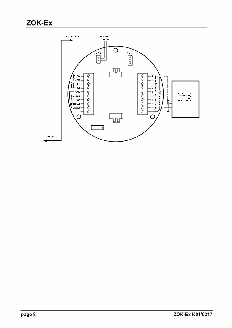
Outputs (only ZOK-E2/E3/E4/E5):
The ZOK-Ex instruments (except ZOK-E1) are certified to provide one (two) of the outputs i.e. Analogue, switching or pulse. To obtain an output, external power is required to be sourced from a certified associated apparatus located in the safe area. In all cases the entity parameters of the associated apparatus must not exceed those of the ZOK-Ex series instrument being: Vi = 28 VDC, Ii = 100 mA, Pi = 0.7 W
1. Two wire 4-20 mA loop powered output (ZOK-E3/E4): The ZOK-Ex instrument can be powered from a two wire 4-20 mA loop, if the input sensor requires no power from the ZOK-Ex instrument (reed switch or certified induction coil sensor).
ZOK-Ex
page 10 ZOK-Ex K01/0217
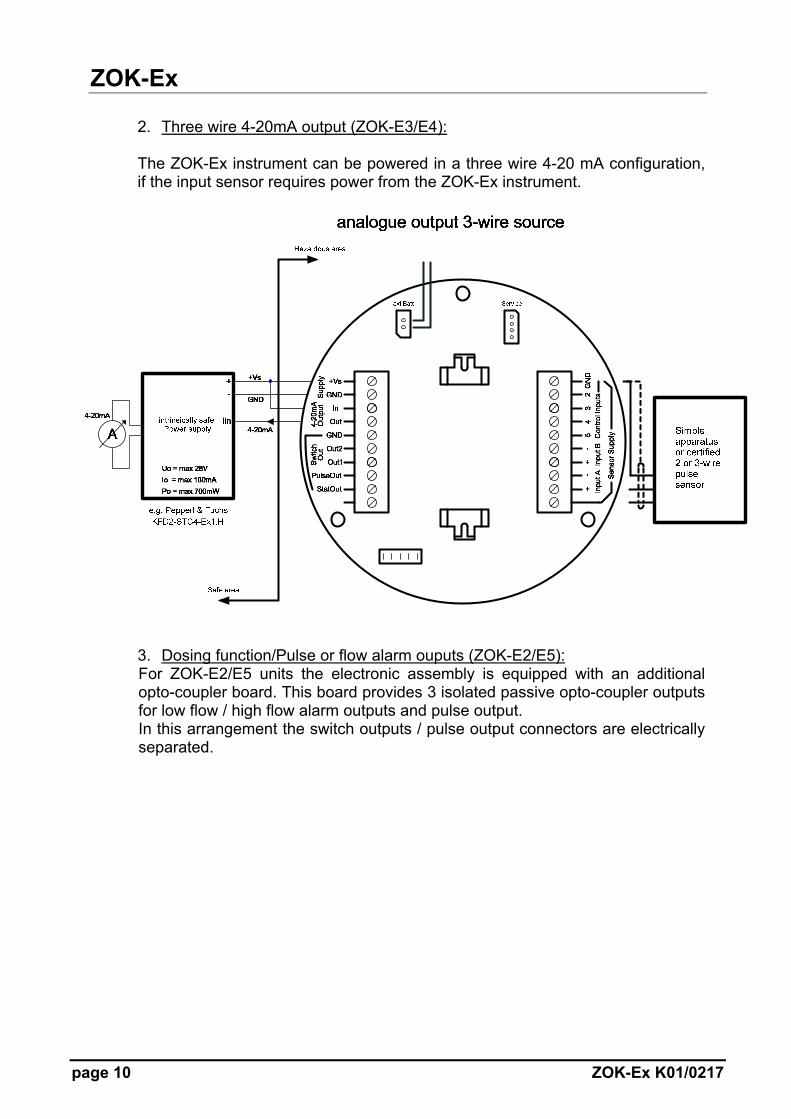
2. Three wire 4-20mA output (ZOK-E3/E4): The ZOK-Ex instrument can be powered in a three wire 4-20 mA configuration, if the input sensor requires power from the ZOK-Ex instrument.
3. Dosing function/Pulse or flow alarm ouputs (ZOK-E2/E5): For ZOK-E2/E5 units the electronic assembly is equipped with an additional opto-coupler board. This board provides 3 isolated passive opto-coupler outputs for low flow / high flow alarm outputs and pulse output. In this arrangement the switch outputs / pulse output connectors are electrically separated.

ZOK-Ex
ZOK-Ex K01/0217 page 11
For ZOK-E5 with pulse output
For ZOK-E2 with dosing function or for ZOK-E5 with high and low flow alarm outputs

ZOK-Ex
page 12 ZOK-Ex K01/0217
Note: It is possible to use all 3 outputs (4-20 mA, pulse and switching outputs) or any two outputs at the same time but only with the help of different isolating amplifiers i.e. supplying all the I.S isolators separately from one another. Associated Apparatus
All certified isolators with suitable entity parameters are permitted to be used with ZOK-Ex electronic options.
7. Wiring
In addition to the wiring requirements of the ZOK-Zx Instruction Manual, appropriate local rules, regulations and directives governing wiring practices for I.S. installations must be followed. These include but are not limited to cable lengths, segregation, routing and identification of I.S. cabling. With regards to cable selection and allowable length the associated apparatus capacitance and inductance parameters must not be exceeded by the sum of the capacitances and the sum of the inductances within the loop. When calculating allowable cable length use the capacitance and inductance values of the ZOK-Ex from Exi-certificate. Certain regions such as Europe allow the inductance/resistance ratio of the cable to be used instead of the sum of the inductances. In this case the cable inductance/resistance ratio must be lower than the maximum inductance/resistance ratio permitted by the associated apparatus.
8. Programming
Refer to ZOK-Zx Instruction Manual for programming, parameterization.
9. Service
The only replaceable item within the instrument is the ATEX Battery and can be replaced as a complete unit. Only the certified I.S. battery assembly ERS-BATEX036 can be used and can be ordered through Kobold offices.
ZOK-Ex
ZOK-Ex K01/0217 page 13
10. Repair
The ZOK-Ex series instruments must only be repaired by trained personnel using approved spares. Instruments requiring repair must therefore be returned to the manufacturer.
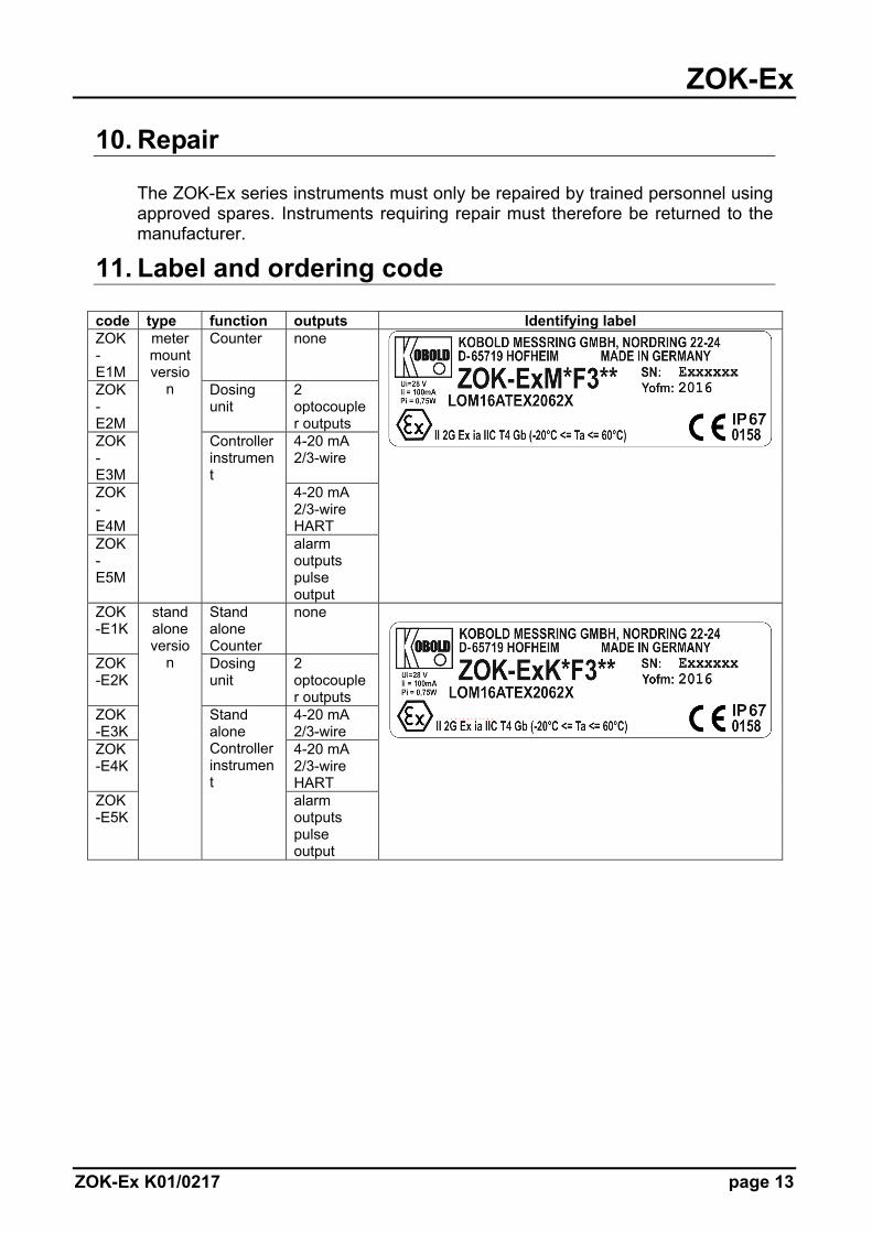
11. Label and ordering code
code type function outputs Identifying label ZOK-E1M
meter mount versio
n
Counter none
ZOK-E2M
Dosing unit
2 optocoupler outputs
ZOK-E3M
Controller instrument
4-20 mA 2/3-wire
ZOK-E4M
4-20 mA 2/3-wire HART
ZOK-E5M
alarm outputs pulse output
ZOK-E1K
stand alone versio
n
Stand alone Counter
none
ZOK-E2K
Dosing unit
2 optocoupler outputs
ZOK-E3K
Stand alone Controller instrument
4-20 mA 2/3-wire
ZOK-E4K
4-20 mA 2/3-wire HART
ZOK-E5K
alarm outputs pulse output

ZOK-Ex
page 14 ZOK-Ex K01/0217
Warning: KOBOLD Intrinsically safe battery assembly P/No. ERS-BATEX036 only approved for
ZOK-Ex instruments mounted in a hazardous area.
I.S. battery assembly KOBOLD Article No. ERS-BATEX036
12. Replacement ATEX Battery
Label on ATEX Battery Note: It is highly recommended to follow the instructions mentioned on the ATEX Battery label.
Replacement Battery Pack
ZOK-Ex
ZOK-Ex K01/0217 page 15
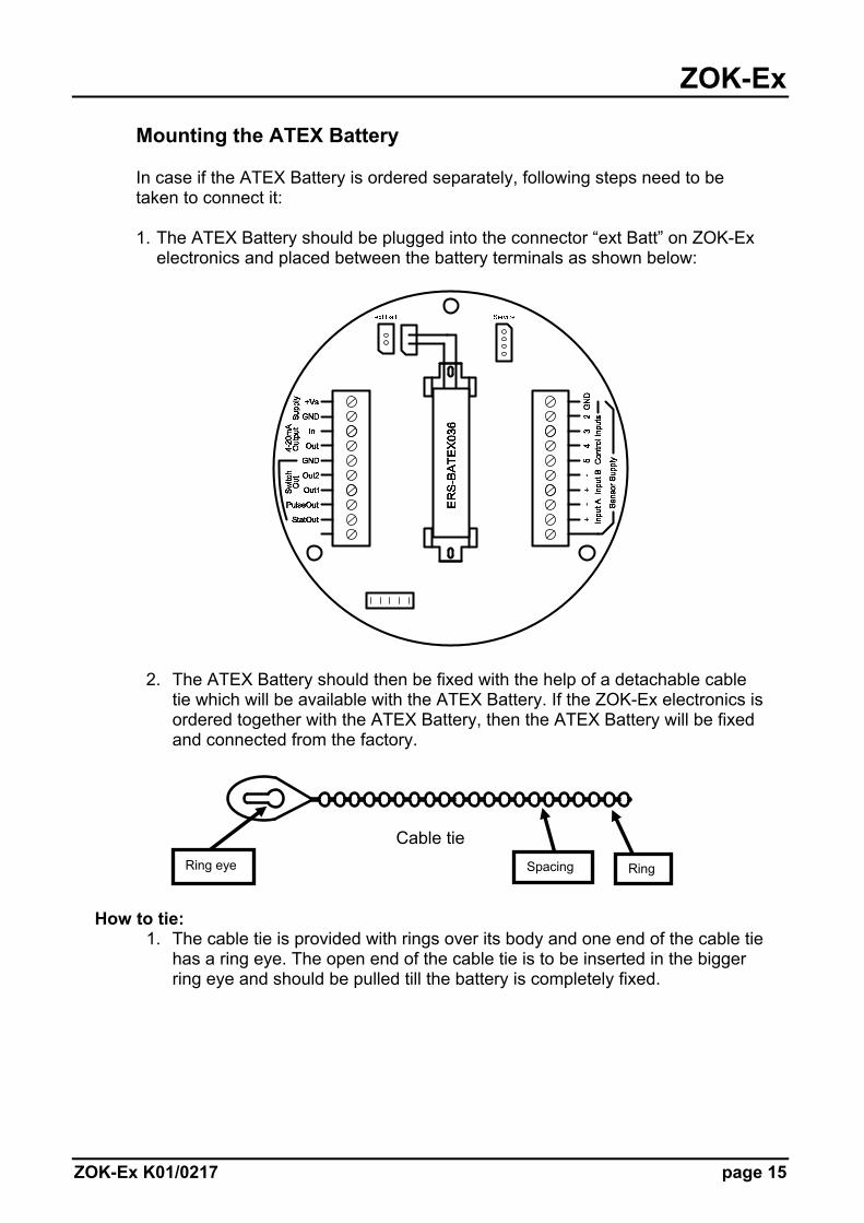
Mounting the ATEX Battery In case if the ATEX Battery is ordered separately, following steps need to be taken to connect it: 1. The ATEX Battery should be plugged into the connector “ext Batt” on ZOK-Ex
electronics and placed between the battery terminals as shown below:
2. The ATEX Battery should then be fixed with the help of a detachable cable tie which will be available with the ATEX Battery. If the ZOK-Ex electronics is ordered together with the ATEX Battery, then the ATEX Battery will be fixed and connected from the factory.
Cable tie
How to tie:
1. The cable tie is provided with rings over its body and one end of the cable tie has a ring eye. The open end of the cable tie is to be inserted in the bigger ring eye and should be pulled till the battery is completely fixed.
Ring eye Ring Spacing

ZOK-Ex
page 16 ZOK-Ex K01/0217
2. Once this is ensured, the spacing between the rings should be pushed into
the narrow side of the ring eye. Hence locking the tie.
How to untie: The above mentioned steps will be carried out in the reverse order to untie the cable tie i.e. To open the cable tie, the spacing between the rings should be pulled out of narrow side of the ring eye. Hence the tie is unlocked. The rings can then be slided out of the bigger ring eye in order to demount and replace the ATEX battery.
ZOK-Ex
ZOK-Ex K01/0217 page 17
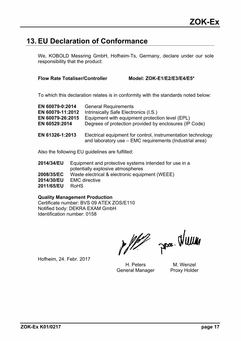
13. EU Declaration of Conformance
We, KOBOLD Messring GmbH, Hofheim-Ts, Germany, declare under our sole responsibility that the product: Flow Rate Totaliser/Controller Model: ZOK-E1/E2/E3/E4/E5* To which this declaration relates is in conformity with the standards noted below: EN 60079-0:2014 General Requirements EN 60079-11:2012 Intrinsically Safe Electronics (I.S.) EN 60079-26:2015 Equipment with equipment protection level (EPL) EN 60529:2014 Degrees of protection provided by enclosures (IP Code) EN 61326-1:2013 Electrical equipment for control, instrumentation technology
and laboratory use – EMC requirements (Industrial area) Also the following EU guidelines are fulfilled: 2014/34/EU Equipment and protective systems intended for use in a potentially explosive atmospheres 2008/35/EC Waste electrical & electronic equipment (WEEE) 2014/30/EU EMC directive 2011/65/EU RoHS Quality Management Production Certificate number: BVS 09 ATEX ZOS/E110 Notified body: DEKRA EXAM GmbH Identification number: 0158
Hofheim, 24. Febr. 2017 H. Peters M. Wenzel General Manager Proxy Holder

ZOK-Ex
page 18 ZOK-Ex K01/0217
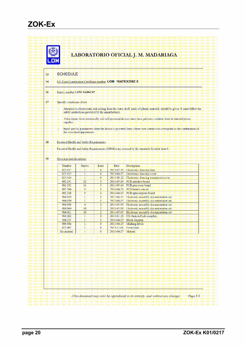
14. Exi Certificate

ZOK-Ex
ZOK-Ex K01/0217 page 19
ZOK-Ex
page 20 ZOK-Ex K01/0217