zero waste zero emissions the eco-factory · the cognitive process resulting in the selection of a...
TRANSCRIPT

PRESENTED BY
Eco-Intelligent Manufacturing The Eco-Factory Grand Challenge – GC2.3
Elliot Woolley, Alessandro Simeone & Nick Goffin Centre for SMART, Loughborough University 03/12/2015

Introduction to eco-intelligent manufacturing Grand Challenge 2.3 Project Update + additional funded projects Clean-in-Place High Speed, Energy Efficient Manufacturing of Photovoltaics
Webinar Contents

The cognitive process resulting in the selection of a course of action among several alternative possibilities
Decision Making
Current tools: 1. Flow of materials, 2. Flow of costs 3. Flow of information
Perception
Goals
Priority Values
Acceptability
Demands
Risk Resources
Judgement

Extend scope of current manufacturing decision making, incorporating:
Environmental considerations Intelligent techniques (artificial intelligence, neural networks, machine learning)
Eco-Intelligent Decision Making
Three decision making timescales: 1. process control, 2. tactical and 3. strategic planning.

Eco-Intelligent Decision Making
Manufacturing Scale
Volume of Data

Process Monitoring Approach
Process Variables Sensorial Perception Data Processing Cognitive Decision Making
Dynamometers Acoustic Emission Accelerometers Power and current sensors Image Acquisition
High Speed Camera Infrared Camera
Statistical Time Domain Frequency Domain

GC2.3 Project July 2013 - July 2016 (£311k) Body of 8 projects IR Monitoring Enterprise level energy management £285k EPSRC Feasibility fund for High Speed, Energy Efficient Manufacturing of Cadmium Telluride Solar Cells January 2015 – July 2016 ~£150k Innovate UK Technology Inspired Innovation – Self-Optimising Clean-in-Place (subject to our consortium accepting the offer and submitting the required documents) January 2016 – December 2016
Project Update
PRESENTED BY
A. SIMEONE Clean-in-place Monitoring

Definition Cleaning industrial equipment without disassembling.
Main Issues
Use of hazardous chemicals Use of water and energy Time
State-Of-The-Art
Manual inspection methodologies
Objective Real-time monitoring system
Introduction CLEAN-IN-PLACE PROCESS

Research Framework
Elements involved What to monitor How to monitor

Research Methodology

Research Methodology 1. FOULING APPLICATION

Research Methodology 2. WASHING CYCLE
Flow Spray ball Temperature
Detergent Draining

Research Methodology IMAGE ACQUISITION
Nikon D3100
Camera
Sigma 10-20mm
Zoom
UV 18W Blacklight Blue Tube Unit
UV lights
Digicam Control
Time-lapse

RGB Green Channel BW
Research Methodology IMAGE PROCESSING

Experimental Setup GENERAL SCHEME

Experimental Setup CONFIGURATION

Research Methodology 5. DECISION MAKING SUPPORT - TRANSFORMATION OF PIXELS IN MM2
Bottom 1cm2 ~ 2000px
Side
1cm2 ~ 3000px

Decision Making THICKNESS ANALYSIS

Results

Results ICE CREAM TESTS

Experimental campaign of 15 tests using 3 different fouling agents was carried out. Images were remote and automated acquired using a set of UV lights and a digital camera. Image processing was carried out extracting the Green Channel of every image and transforming it into a Black and White image. Fouling pixels in the Black and White images were transformed into surface units through the application of an experimental methodology. Fouling removal and water flow vs cleaning time were represented in plots for every test performed.
Conclusions
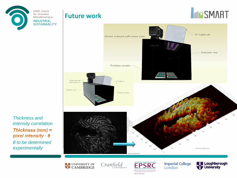
Future work
Thickness and intensity correlation
θ to be determined experimentally

PRESENTED BY
High Speed, Energy Efficient Manufacturing of Photovoltaics Nick Goffin Centre for SMART, Loughborough University 03/12/2015

Embedded energy is the energy required to manufacture the PV module. Embedded energy from different types of PV module (Peng et al.) (mean values):
Mono-silicon PV ~ 3400 MJ/m2
Multi-silicon PV ~ 3800 MJ/m2
Thin-film PV technologies: a-Si ~ 1200 MJ/m2
CIGS ~ 1070 MJ/m2 CdTe ~ 920 MJ/m2
Embedded energy
Glass and encapsulation
(42%)
CdTe (46%)
TCO (10%) Back contact
CdS

Optical inspection of CdTe panels
FTO
CdS
CdTe Voids
Stacking faults
Advantages of using an optical inspection system: In-situ, non-invasive measurements
Can provide high-speed online real-time analysis
Allows panel quality to be inspected while in production
Stacking faults and voids cause failures in panels.

Optical Inspection of CdTe panels
Laser spot Diffraction rings
CSS
MS

Current annealing processes typically use a furnace to heat the entire panel for approximately 8 mins
Energy intensive Inefficient Slow
The use of a laser offers improvements: Energy reduction by only heating the top surface rather than the entire panel Decrease in annealing time from 8 mins down to approximately 15 seconds Energy resilience – the ability to halt process at any time with no repercussions “Reel-to-reel” continuous production rather than batch production Use of polymer or other non-glass substrate
Using lasers for CdTe annealing

Laser beam characterisation
Laser beams take on a TEM00 energy distribution

Using Holographic Optical Elements for thermal control
Laser beam thermal control is achieved via use of Holographic Optical Elements (HOE’s)
Gaussian beam HOE Optimised beam
• HOE’s are manufactured either using e-beams or plasma etching, based on a computer-generated image

Laser beam optimisation
The laser beam thermal distribution was optimised to give greater uniformity in temperature distribution.
0
500
1000
1500
2000
2500
0 2000 4000 6000 8000 10000 12000
y-ax
is co
-ord
inat
e (µ
m)
x-axis co-ordinate (µm)
10 x 10 mm pedestal beam
10 x 10 mm rugby posts beam
Beam traverse “Pedestal”
beam
“Rugby posts” beam

808 nm wavelength selected as optimum Long enough for infrared thermal processing But not too long – CdTe is transparent to the majority of the infrared spectrum
Laser annealing equipment
Visible spectrum
750 nm
Infrared thermal processing
850 nm – CdTe completely transparent
Laser wavelength must be within this region

Laser annealing tests
DIC optical micrograph of unprocessed surface
DIC optical micrograph of processed surface
5 mm 1/e2 beam diameter, 10 W laser power, 2.5 mm/s
traverse rate

Solar photovoltaics are growing in importance worldwide, with CdTe thin film technology showing the most promise for development Optical inspection offers the ability to detect manufacturing faults non-invasively in real time Laser annealing offers advantages compared to traditional methods, principally:
Speed Energy efficiency Energy resilience
Thermal effects of 808 nm laser beams have been observed experimentally. Experiments with holographic optics are due to commence
Conclusions

Thank You