zenith - Век Вендинга · zenith fresh brew instant uk english edition 2 07-2002 ......
TRANSCRIPT

INSTALLATION, OPERATING AND MAINTENANCE MANUAL
Zenith Fresh Brew
Instant
UK English
EDITION 2 07-2002
DOC. NO. H 148U 03


DICHIARAZIONE DI CONFORMITA’
DECLARATION OF CONFORMITY
DÉCLARATION DE CONFORMITÉ
KONFORMITÄTSERKLÄRUNG
DECLARACIÓN DE CONFORMIDAD
DECLARAÇÃO DE CONFORMIDADE
VERKLARING VAN OVEREENSTEMMING
INTYG OM ÖVERENSSTÄMMELSE
OVERENSSTEMMELSESERKLÆRING
YHDENMUKAISUUSTODISTUS
Dichiara che la macchina descritta nella targhetta di identificazione, è conforme alle disposizioni legislative delle direttive:89/392, 89/336, 73/23 CEE e successive modifiche ed integrazioni.
Declares that the machine described in the identification plate conforms to the legislative directions of the directives: 89/392, 89/336, 73/23 EEC and further amendments and integrations.
Déclare que l’appareil décrit dans la plaque signalétique satisfait aux prescriptions des directives: 89/392, 89/336, 73/23 CEE et modifications/intégrations suivantes.
Erklärt, daß das im Typenschild beschriebene Gerät den EWG Richtlinien 89/392,89/336, 73/23 sowie den folgenden Änderungen/Ergänzungen entspricht.
Declara que la máquina descripta en la placa de identificación, resulta conforme a las disposiciones legislativas de lasdirectivas: 89/392, 89/336, 73/23 CEE y modificaciones y integraciones sucesivas.
Declara que o distribuidor descrita na chapa de identificação é conforme às disposições legislativas das directivas CEE89/392, 89/336 e 73/23 e sucessivas modificações e integrações.
Verklaart dat de op de identificatieplaat beschreven machine overeenstemt met de bepalingen van de EEG richtlijnen89/392, 89/336 en 73/23 en de daaropvolgende wijzigingen en aanvullingen.
Intygar att maskinen som beskrivs på identifieringsskylten överensstämmer med lagstiftningsföreskrifterna i direktiven:89/392, 89/336, 73/23 CEE och påföljande och kompletteringar.
Det erklæres herved, at automaten angivet på typeskiltet er i overensstemmelse med direktiverne89/392, 89/336 og 73/23 EU og de senere ændringer og tillæg.
Forsikrer under eget ansvar at apparatet som beskrives i identifikasjonsplaten, er i overensstemmelse med vilkårene iEU-direktivene 89/392, 89/336, 73/23 med endringer.
Vahvistaa, että arvokyltissä kuvattu laite vastaa EU-direktiivien 89/392, 89/336, 73/23 sekä niihin myöhemmin tehtyjenmuutosten määräyksiä.
Valbrembo, 03/05/2001
ANTONIO CAVO
C.E.O

1© by NECTA VENDING SOLUTIONS SpA 07-2002 148 03
INTRODUCTION PAGE 2IDENTIFICATION OF THE VENDING MACHINE PAGE 2
IN CASE OF FAILURE PAGE 2
TRANSPORT AND STORAGE PAGE 2
USING THE VENDING MACHINES PAGE 3
POSITIONING THE VENDING MACHINE PAGE 3
WARNING FOR INSTALLATION PAGE 3
PRECAUTIONS IN USING THE MACHINE PAGE 3
WARNING FOR SCRAPPING PAGE 3
DIMENSIONS PAGE 3
TECHNICAL SPECIFICATIONS PAGE 4
POWER CONSUMPTION PAGE 5
VARIABLE COMBINATION LOCK PAGE 5
ACCESSORIES PAGE 5
LOADING AND CLEANING PAGE 6DOOR SWITCH PAGE 6
MAINTENANCE AND DISINFECTION PAGE 6
CONTROLS AND INFORMATION PAGE 6
LOADING CUPS PAGE 7
LOADING SUGAR AND INSTANT PRODUCTS PAGE 7
LOADING STIRRERS PAGE 7
SANITISING THE FOODSTUFFCIRCUITS AND THE MIXERS PAGE 8
WEEKLY CLEANING OF THE BREWER UNIT PAGE 9
REPLACING THE FILTER CARTRIDGE PAGE 9
SUSPENDING FROM USE PAGE 9
INSTALLATION PAGE 10UNPACKING THE VENDING MACHINE PAGE 10
INSERTING THE PRODUCT LABELS PAGE 10
INSTALLING THE FILTER CARTRIDGE PAGE 10
CONNECTING THE MACHINETO THE WATER MAINS PAGE 11
CONNECTING TO THE POWER SUPPLY PAGE 11
DOOR SWITCH PAGE 11
INSTALLING THE PAYMENT SYSTEM PAGE 12
CLEANING THE SOFTENER RESINS PAGE 12
BREWER UNIT OPERATION PAGE 12
DISPENSING CYCLE PAGE 12
CHECKING AND ADJUSTINGTHE MACHINE SETTINGS PAGE 13
STANDARD SETTINGS PAGE 13
CUP SENSOR PAGE 13
OPERATING MODES PAGE 13
USER INTERFACE PAGE 13
NORMAL OPERATING MODE PAGE 14
FILLER MENU PAGE 14
STATISTICS PAGE 14
SELECTION PRICES PAGE 15
CHANGE TUBES CONTROL PAGE 15
DISPLAYING THE TEMPERATURE PAGE 15
TEST DISPENSING PAGE 15
GSM PRE-ALARMS PAGE 15
EVADTS TRANSFER PAGE 15
TECHNICIAN MENU PAGE 15
FAILURES PAGE 16
PROGRAMMING PARAMETERS PAGE 17
SELECTIONS PAGE 19
VENDING MACHINE PARAMETERS PAGE 19
DISPLAY PAGE 20
MISCELLANEOUS PAGE 20
CUSTOMISING THESELECTION COMPOSITION PAGE 20
EVADTS PAGE 22
STATISTICS PAGE 22
TEST PAGE 23
MISCELLANEOUS PAGE 24
MACHINE INFORMATION PAGE 24
INITIALISING PAGE 24
GSM PAGE 24
PROGRAMMER (OPTIONAL) PAGE 24
AUTOMATIC SETUP TRANSFER PAGE 24
TRANSFERRED DATA PAGE 25
CONFIGURING THE LANGUAGE PAGE 25
MAINTENANCE PAGE 25INTRODUCTION PAGE 25
BREWER UNIT MAINTENANCE PAGE 25
BOILER MAINTENANCE PAGE 26
ANNUAL SANITISING PAGE 26
PRINTED BOARD FUNCTIONSAND INDICATOR LIGHTS PAGE 26
CPU BOARD PAGE 26
BOILER CONTROL BOARD PAGE 27
ACTUATION BOARD PAGE 27
EXPANSION BOARD PAGE 28
CONFIGURING THE ELECTRONIC BOARDS PAGE 28
SOFTWARE UPDATE PAGE 28
HYDRAULIC SYSTEM PAGE 29
FILLER MENU PAGE 32
TECHNICIAN MENU PAGE 39
WIRING DIAGRAMS PAGE 64
TABLE OF CONTENTS

2© by NECTA VENDING SOLUTIONS SpA 07-2002 148 03
INTRODUCTION
This technical documentation is part and parcel of thevending machine and must always follow the machinein case it is moved or transfer of ownership, so as toallow consultation by different operators.
Before starting installation and using the machine, it is firstnecessary to carefully read and understand the instructionscontained in this manual, as they offer important informa-tion on installation safety, operating instructions and main-tenance.
This manual is divided into three chapters.
The first chapter describes the loading and routine main-tenance operations which are carried out in areas of themachine accessible with simple use of the door key,without using any other tools.The second chapter contains the instructions for correctinstallation and all information necessary for optimum useof the machine.The third chapter describes maintenance operations whichinvolve the use of tools to access potentially dangerousareas.
The operations described in the second and thirdchapters must be carried out only by personnel whohave the specific knowledge of the machine function-ing from a point of view of electrical safety and healthregulations.
IDENTIFICATION OF THE VENDINGMACHINE AND ITS CHARACTERISTICS
This manual describes the following machines:
- models with two units for brewing FB coffee or FB teaand reconstituting instant products;
- models with one unit for brewing FB coffee or FB teaand reconstituting instant products;
- instant models for reconstituting instant products.
Every machine is identified by its own serial number,indicated on the rating plate attached inside the cabinet onthe right side.This plate is the only one acknowledged by the manufac-turer as the identification of the apparatus, and carries allthe data which readily and safely give technical informationsupplied by the manufacturer. It also assists in the spareparts management.
IN CASE OF FAILURE
In most cases, any technical problems are corrected bysmall repair operations; however, before contacting themanufacturer we recommend that this manual be readcarefully.Should there be failures or malfunctions that cannot besolved, then contact:NECTA VENDING SOLUTIONS SpAVia Roma 2424030 ValbremboItaly - Tel. +39 035606111
TRANSPORT AND STORAGE
To prevent any damage, special care should be taken whenloading or unloading the vending machine.The machine can be lifted by a motor-driven or manual forklift truck, and the forks are to be placed underneath themachine from the side clearly indicated by the symbol onthe cardboard package.
Do not:
- overturn the vending machine;
- drag the vending machine with ropes or similar;
- lift the vending machine by its sides;
- lift the vending machine with slings or ropes;
- shake or jolt the vending machine and its packing.
The machine should be stored in a dry room where thetemperature remains between 0°C and 40°C.Avoid stacking machines one on top of the other and alwayskeep it upright as indicated by the arrows on the packing.
Boiler dataWater mainscharacteristics
Absorbed power
Operating voltage
Model
Product code
Current
Frequency
Serial number
Type

3© by NECTA VENDING SOLUTIONS SpA 07-2002 148 03
USING THE VENDING MACHINES OF HOTDRINKS IN OPEN CONTAINERS(Ex.: plastic cups, ceramic cups, jugs)
The vending machines of drinks in open containers shouldbe used only to sell and dispense drinks obtained by:
- brewing products like coffee and tea;
- reconstituting instant and lyophilized products;
These products should be declared by the manufacturer as"suitable for automatic vending" in open containers.
The dispensed products should be consumed immedi-ately. They should never be preserved and/or packedfor later consumption.
Any other use is unsuitable and thus potentially dangerous.
POSITIONING THE VENDING MACHINE
The vending machine is not suitable for outdoor installation.It must be installed in a dry room where the temperature isbetween 2°C and 32°C, and not where water jets are usedfor cleaning (e.g. in large kitchens, etc.).The machine should be placed close to a wall, so that theback panel is at a minimum distance of 4 cm from it andcorrect ventilation may be ensured.The machine must never be covered with cloth or the like.The machine should be positioned with a maximum inclina-tion of 2°.If necessary provide proper levelling by way of the adjust-able feet included (see Figure 11).
WARNING FOR INSTALLATION
The machine installation and the following mainte-nance operations should be carried out by qualifiedpersonnel only, who are trained in the correct use of themachine according to the standards in force.
The machine is sold without payment system, therefore theinstaller of such a system has sole responsibility for anydamage to the machine or to things and persons caused byfaulty installation.
The integrity of the vending machine and its conformitywith the rules and regulations in force for its relevantsystems must be checked by qualified personnel atleast once a year.
All packing materials shall be disposed of in a manner whichis safe for the environment.
PRECAUTIONS IN USING THE MACHINE
The following precautions will assist in protecting theenvironment:
- use biodegradable products only to clean the machine;
- adequately dispose of all containers of the productsused for loading and cleaning the machine;
- switch the machine off during periods of inactivity, thusachieving considerable energy savings.
WARNING FOR SCRAPPING
Whenever the machine is to be scrapped, the laws in forceregarding environment protection should be strictly ob-served. More specifically:
- ferrous and plastic materials and the like are to bedisposed of in authorized areas only;
- insulating materials should be recovered by qualifiedcompanies.
DIMENSIONS
Height 1830 mm
Width 850 mm
Depth 780 mm
Overall depth with door open 1540 mm
Weight:
thgieW stinU2 tinU1 tnatsnI
gK 532 522 022

4© by NECTA VENDING SOLUTIONS SpA 07-2002 148 03
AVAILABLE ADJUSTMENTSFresh brew: coffee or tea dose, water dose. brewing time
and drying time.Instant: time adjustment for coffee, instant products
and water doses.Temperature control programmable via software.
CONTROLS
- Presence of cups
- Presence of water
- Fresh brew unit in start position
- Liquid waste container full
- Operating temperature reached
- Position of mobile dispensing spouts
SAFETY DEVICES
- Door switch
- Manual-reset boiler safety thermostats
- Air-break float jamming
- Overflow solenoid valve
- Float for full liquid waste container
- Instant boiler anti-overboiling thermostat
- Boiler sensor short-circuit/failure control
- Timer protection for:
Brewer unit ratiomotorFresh-brew product dispensing
- Overheating protection for:
Doser unitsBrewer unit ratiomotorElectric mixers
- Fuse protection for:
Main electrical circuitBoard power supply transformerCoin mechanism power supply
CAPACITY OF CONTAINERS
Fresh brew tea 5,8 KgFresh brew coffee 5,2 KgSugar 4,4 KgPowdered milk 1,4 KgInstant coffee 3,9 KgChocolate 3,4 KgSoup 3,9 Kg
)~V032(spmaL .N W
slenapgnisitrevdA 2 51
unemnoitceleS 3 8
)lanoitpo(lanretnI 1 8
TECHNICAL SPECIFICATIONS
Power supply voltage 230 V~Frequency 50 Hz
Installed power 2400 W
Lighting lamps power
CUP DISPENSER
Suitable for cups with a rim diameter of 70-71 mm. with acapacity of approximately 900 cups;
PAYMENT SYSTEM
The machine is supplied with all electrical prearrangementfor systems with Executive, BDV and MDB protocol, aswell as for installation of 24 V validators.Beside the coin mechanism housing, suitable space isprovided for the installation (optional) of the most widelyused payment systems.
SALES PRICES
A different price in 4 programmable time periods can be setfor each selection;the standard setting has the same sales price for allselections without any time bands.
ENERGY SAVING.Option of setting the automatic switch-off of lamps and/orboilers over 3 daily time bands on a weekly basis, to saveelectric power during the machine idle periods.
JUG FACILITIES AND FREE VEND
Using a special key, up to 9 freshly brewed drinks can bedispensed to fill a jug without releasing any cups; alterna-tively to get free dispensing of normal selections.
COIN BOXMade of aluminized plate.Cover and lock are available as accessories.
WATER SUPPLY
From the mains, with a pressure of 5 to 85 N/cm2 (0,5÷8,5bar).

5© by NECTA VENDING SOLUTIONS SpA 07-2002 148 03
POWER CONSUMPTION
The machine power consumption depends on many fac-tors, such as the temperature and ventilation of the roomwhere it is installed, the inlet water and boiler temperature,etc.Under average conditions, and namely:
- Ambient temperature: 20° C
- Instant boiler temperature 90° C
- Inlet water temperature: 18° C
- Water (average) per selection: 90 cc
the following power consumption levels resulted:
The above power consumption calculated from averagedata should only be taken as an indication.
VARIABLE COMBINATION LOCK
Some machine models are fitted with a variable combina-tion lock.The lock is supplied with two silver colour keys to be usedfor normal opening and closing.The lock can be customised by using a kit, available asaccessory, which permits changing of the lock combina-tion.This kit includes a change key (black) for the current lockcombination as well as change (gold) and use (silver) keysfor the new combination.Sets of change and use keys with other combinations canbe supplied on request.Additional sets of use keys (silver) may be requested,indicating the combination stamped on the keys.Generally, only the use key (silver) is used, while thecombination change keys (gold) can be kept as spares.
Do not use the change key for normal opening, as it maydamage the lock.
TO CHANGE COMBINATION DO AS FOLLOWS:
- insert the current change key (black) and rotate to thechange position (reference notch at 120°);
- remove the current change key and insert the changekey (gold) with the new combination;
- rotate to the close position (0°) and remove the changekey.
The lock will now have the new combination.
Keys with the old combination cannot be used for thenew combination.
ACCESSORIES
A wide range of accessories can be installed on themachine to change its performance:The various kits are supplied with their own installationinstructions, which must be strictly observed to ensure themachine's safety.
Installation and the following testing operations, mustbe carried out only by qualified personnel who have thespecific knowledge of the machine functioning from apoint of view of both electrical safety and health regu-lations.
)hW(noitpmusnocrewoP tinu1 tnatsnI
erutarepmetgnitarepohcaeroT 005 073
yb-dnatsforuohhcaeroF 072 512
Fig. 1

6© by NECTA VENDING SOLUTIONS SpA 07-2002 148 03
DOOR SWITCH
When opening the door a special switch disconnects thepower from the machine electrical system to allow theoperations described below, regarding loading and routinecleaning, in full safety.
All operations requiring the machine to be energizedshould be carried out by qualified personnel ONLY,informed about the specific risks of such situation.
The service power socket, permanently live, is sized forsmall tools; care should be taken not to exceed the ratingindicated on the specific plate.To energize the system with the open door, simply insertthe special key into the slot (see Figure 1).The door can be closed only after removing the key.
Do not leave the vending machine unattended with thedoor open.
MAINTENANCE AND DISINFECTION
According to current legislated health and safety rules andregulations, the operator of an automatic vending machineis responsible for the hygiene and the maintenance of thefoodstuff circuits, to prevent formation of bacteria.
At installation the hydraulic circuits and the parts incontact with foodstuff should be fully sanitised toremove any bacteria which might have formed duringstorage.
It is advisable that specific sanitising agents (such aschlorine-based detergents or similar) are used for clean-ing also the surfaces which are not directly in contact withfoodstuff.Some parts of the machine can be damaged by strongdetergents.The manufacturer declines all responsibility for any dam-age to persons resulting from failure to comply with currentregulations.
Before starting any maintenance operations requiringparts of the unit to be removed, the machine mustalways be disconnected from the power supply.
CONTROLS AND INFORMATION
All user controls and information are conveniently locatedon the external side of the door (see Figure 3).
The labels with the selection menu and instructions, sup-plied with the machine, must be inserted at the time ofinstallation.
The programming button, to access the machine functions,and the mixer cleaning button are located on the coinmechanism compartment cover.
Chapter 1LOADING AND CLEANING
Fig. 2
1 - Door switch2 - internal lamp switch (optional)3 - Network fuses4 - Permanently live socket (230v~ 2 A. Max)5 - Mechanical counter6 - RS232 serial port7 - Mixer cleaning button8 - Programming button
Fig. 3
1 - Modular elements for payment systems2 - Alphameric display (4x20)3 - Coin slot-return.4 - Operating instructions labels5 - Coin return flap6 - Dispensing compartment7 - Lock8 - Selection menu9 -Coffee dose selection

7© by NECTA VENDING SOLUTIONS SpA 07-2002 148 03
LOADING SUGAR AND INSTANT PRODUCTS
A self-adhesive label indicating the product is attached oneach container.After lifting their cover, fill the single containers with theappropriate products, taking care not to compress them toprevent packing. Make sure the products do not containany clots.
LOADING STIRRERS
In order to load correctly the double stirrer stacker do asfollows:
- remove the inner and outer stirrer weights, from above (seeFigure 5);
- ensure that the inner column is pushed back using thespecial lever, so that the stirrers from the outer guide (inview) are dispensed first. By lifting the lever handle to liftthe residual stirrers, the column can be pushed towardsthe inside until the release mechanism is reset.
With the profile positioned inside the stirrer columns, 90 or105 mm stirrers can be dispensed;Without the profile, 115 mm stirrers can be dispensed.
LOADING CUPS
When loading cups for the first time (i.e. with the cupdispenser completely empty) do as follows:
- disconnect the electricity from the machine;
- remove the cover of the cup container;
- fill the columns with cups, except the one aligned with thedispensing opening;
- switch the machine on and the full column will bepositioned automatically over the dispensing opening;
All operations requiring the machine to be energizedshould be carried out by qualified personnel ONLY,informed about the specific risks of such situation.
- fill the empty column;
- release one or more cups with the special button andreplace the cover.
Fig. 4
1 - Cover2 - Cup stacker3 - Cup release button4 - Shelf release lever
1 - Double column2 - Stirrer profile3 - Removable weight4 - Reset lever5 - External column "empty" microswitch6 - Internal column lock device7 - Thermo-expander
Fig. 5

© by NECTA VENDING SOLUTIONS SpA 8 07-2002 148 03
SANITISING THE FOODSTUFFCIRCUITS AND THE MIXERS
When installing the unit, and then at least once a week oreven more frequently according to the use of the machineand the quality of the inlet water, the mixers and thedispensing conduits must be thoroughly sanitised (cleanedand disinfected), to guarantee proper hygiene of the dis-pensed products.
In order to make sanitising operations quicker, somespare parts, which can replace the parts to be cleaned,are supplied with the machine.
The parts to be cleaned are as follows:
- mixer and instant drink dispensing conduit;
- coffee dispensing spout;
- cup chute;
- dispensing compartment;
- remove the covers, the powder and the water funnels, thefeeders, the powder deposit drawers and the mixer wheelsfrom the mixers (see Figure 6);
Fig. 7
1 - Powder feeder2 - Powder funnel3 - Powder deposit drawer4 - Water funnel5 - Feeder6 - Mixer wheel7 - Tray drain8 - Overflow tray9 - Splash guard ring
Fig. 6
- a splash guard ring is also fitted in the fresh coffee andmilk mixers; this must be cleaned and then replaced inthe same mixers;
- in order to remove the wheels, block the disk fitted on themixer shaft with a finger (fig. 7);
- wash all parts with detergent being sure that all visibleresidue and product layers are mechanically removed,using a brush if necessary;
Disinfection should be carried out using chlorine-baseddetergents;
- soak all components for approx. 20 minutes in a containerfilled with the previously prepared chlorine-based deter-gent;
- reinstall the feeders and the water funnels;
- reinstall the powder deposit drawers and the powderfunnels after thoroughly drying them.
After reinstalling all parts the following is howeverrequired:
- enter into "Filler" mode to clean the mixers (see relevantparagraph) and add a few drops of the chlorine-baseddetergent in the various funnels
- After disinfection thoroughly rinse all components toensure that all residue of the detergent solution is re-moved.
All operations requiring the machine to be energizedshould be carried out by qualified personnel ONLY,informed about the specific risks of such situation.Some models, with the fresh product being dispenseddirectly into the cup, are fitted with a special spout (seefig. 8), as alternative to the splash guard ring, preventingthe pressure created by the brewer piston from beingdischarged into the cup.
Fig. 8
1 - Tea dispensing spout2 - Plug
Also this spout and its plug must be cleaned following thesame procedure indicated for the mixers.

9© by NECTA VENDING SOLUTIONS SpA 07-2002 148 03
WEEKLY CLEANINGOF THE BREWER UNIT
On a weekly basis, besides cleaning the external parts ofthe brewer unit to remove any powder residue, especiallyin the area of the funnel, also the parts of the unit whichcome into contact with the drink should be sanitised.
These operations must be carried out with the powerswitched off.
- Undo the fastening screw and remove the cover toaccess the brewer unit.
- Disconnect the hose from the mixer and remove themixer (9-1) from the brewing cylinder.
- Disengage the cylinder from the assembly by pulling therelease lever (9-2) and slide it out of the piston controlfork (9-3) by pulling it outwards.
- Slide out the piston from the cylinder.
- Extract the sliding filter holder (9-4) from the guide (9-7) releasing the link (9-6) from the stop lever (9-5).
- Extract the scraper assembly (9-8).
- Wash all parts with mild detergent, being sure that allvisible residue and product layers are mechanicallyremoved, using a brush if necessary.
- Soak them for approx. 20 minutes in a container filled witha chlorine-based detergent similar to the one used for themixers.
Fig. 10
Do not use screwdrivers or any other sharp objectsagainst the filter holder seal and do not place the sealon surfaces which may damage it.
If the metal filter is clogged, it should be replaced orcleaned with a specific product.To remove the metal filter, first pull out the seal from itsedge (see fig. 10).The filter must be cleaned at least every 2,500 selections.To reassemble the brewer unit follow the above instructionin the reverse order, making sure that the seal is installedbefore the filter.
REPLACING THE FILTER CARTRIDGE
Every 30,000 drink selections or every 6 months, themains metal filter cartridge should be replaced accordingto the procedure described in section "Installing the filtercartridge".
SUSPENDING FROM USE
If for any reason the machine is switched off for a periodexceeding the use-by date of the products, the following willbe necessary:
- completely empty the containers and thoroughly washthem with the chlorine-based detergents used to clean themixers.
- completely empty the air-break and the instant productboiler, loosening the clamp on the hose.
Before reinstating the machine, the cleaning andsanitising procedure described in the section "Yearlysanitising" should be carried out.
Fig. 9
1 - Mixer2 - Cylinder release lever3 - Piston control lever4 - Sliding filter holder5 - Control link6 - Filter holder release lever7 - Guide8 - Scraper assembly

© by NECTA VENDING SOLUTIONS SpA 10 07-2002 148 03
Installation and the following maintenance operationsshould be carried out with the machine switched on andtherefore by qualified personnel only, who are trained inthe correct use of the machine and informed about thespecific risks of such situation.
The machine should be installed in a dry room wherethe temperature remains between 2° C and 32° C.
At installation the hydraulic circuits and the parts incontact with foodstuff should be fully sanitised toremove any bacteria which might have formed duringstorage.
UNPACKING THE VENDING MACHINE
After removing the packing, check that the machine is notdamaged.If in doubt do not use the machine.
No packing elements (i.e. plastic bags, polystyrenefoam, nails, etc.) should be left within the reach ofchildren, as they are potentially dangerous.
Packing materials must be disposed of in authorized areasonly, and all recyclable materials must be recovered byspecialised companies.
Important notice!!The machine should be positioned with a maximum inclina-tion of 2°.If necessary provide proper levelling by way of the adjust-able feet included (see Figure 11).
INSERTING THE PRODUCT LABELS
To be able to insert the product labels, the front panel mustbe removed. Undo the fastening screws and then press theclamping tangs (see fig. 12).The labels must be inserted into the special slots with theopening positioned alternating on the left and right handside.According to the model, some buttons may not be used(refer to the selection dose table).The machine is supplied also with the self-adhesive labelsto be attached to the product containers according to thelayout (refer to the selection dose table).
INSTALLING THEFILTER CARTRIDGE
Make sure that the coloured ring is in thelower position (turned to the left).Wet the two cartridge seals (see Fig.13).
a) insert the cartridge into the ring,
b) turn the cartridge to the right,
c) turn the ring fully to the right untillocking the cartridge;
d) block the ring into place by loweringthe lever, so that it is just in front of thering nose.
NOTE: The lever is used as a tap.
lever lifted = tap closed
lever lowered = tap open.
Fig. 12
1 - Label support2 - Clamping tangs3 - Fastening screws4 - Product labels
1 - Lock lever2 - Coloured ring3 - Cartridge
Fig. 13
Fig. 11
1 - Adjustable foot
Chapter 2INSTALLATION

11© by NECTA VENDING SOLUTIONS SpA 07-2002 148 03
CONNECTING TO THE POWER SUPPLY
The vending machine is designed to operate under asingle-phase 230 V~ voltage and is protected by 15 Afuses.Before making the connection, ensure that the ratingcorresponds to that of the power grid, and more specifi-cally:
- the supply voltage rating must be within the rangerecommended for the connection points;
- the main switch should be capable of withstanding thepeak load required, and at the same time ensure properomnipolar disconnection from the power grid with anopening gap of the contacts of at least 3 mm.
The switch, the power outlet and the plug must belocated in an easily accessible position.
The electrical safety of the machine is ensured only whenit is correctly earthed according to the safety standardsin force.
This fundamental safety requirement must be dulyverified, and if in doubt the system must be carefullytested by qualified technicians.The power supply cable is of the type with a fixed plug. Anyreplacement should be carried out by qualified personnelonly, using exclusively cables of the type HO5 RN - F orHO5 V V-F or H07 RN-F with a section of 3x1-1.5 mm2.
Do not use adapters, multiple sockets and/or exten-sions.
Before switching the machine on, be sure it is correctlyconnected to the water mains and the cut-off valve is open.
THE MANUFACTURER DECLINES ALL RESPONSI-BILITY FOR ANY DAMAGE CAUSED BY NON-COM-PLIANCE WITH THE ABOVE MENTIONED PRECAU-TIONS.
DOOR SWITCH
When opening the door a special microswitch disconnectsthe power from the machine electrical system.To energize the system with the open door, simply insertthe special key into the slot (see Fig. 2).
With the door open there is no access to energisedparts. Inside the machine, the only parts that stayenergised are those protected by covers and carryinga plate with the warning “Disconnect the power beforeremoving the protective cover”.
Before removing such covers disconnect the machinefrom the power grid.
The door can be closed only after removing the key fromthe door switch.
CONNECTING THE MACHINETO THE WATER MAINS
The machine must be connected to the drinking watermains. The water pressure must be 5 to 85 N/cm2.
Run some water from the mains until it is clear and withoutimpurities.Use a hose capable of withstanding the water mainspressure and suitable for use with foodstuff (min. insidediameter of 6 mm) to connect the water supply to the fitting(1/4" gas) of the water inlet solenoid valve (see Figure 14).
1 - Water inlet fitting (1/4" gas)2 - Water supply hose3 - Overflow hose4 - Inlet hose fitting
Fig. 14
A good practice is to install the water supply tapoutside the machine in an easily accessible position.
OVERFLOW DEVICE
The water inlet solenoid valve (see Fig. 14) is equippedwith an overflow device which mechanically stops thewater inlet if there is a malfunction in the solenoid valveor in the boiler water level control device.To restore normal operation, proceed as follows:
- drain the water contained in the overflow hose;
- shut off the water supply using the tap outside themachine;
- loosen the nut which secures the solenoid valve supplyhose to relieve the water mains residual pressure andthen tighten again (see Fig. 14);
- open the tap and switch the machine on.

© by NECTA VENDING SOLUTIONS SpA 12 07-2002 148 03
INSTALLING THE PAYMENT SYSTEM
The machine is sold without payment system, there-fore the installer of such a system is responsible forany damage to the machine or to things and personscaused by faulty installation.
- Install the desired coin mechanism according to theappropriate instructions and make sure that the relevantparameters are programmed correctly.
- adjust the selector opening lever bracket to allowcomplete opening of the selector;
- adjust the coin chute according to the type of coinmechanism installed.
FILLING THE WATER SYSTEM
If the air-break device indicates the no-water condition formore than 10 seconds after the machine has beenswitched on, an installation cycle will automatically bestarted, and namely:
- the display will show “OUT OF SERVICE” for the entireduration of the cycle;
- the air-break and the boiler are filled;
N.B.: If there is no water flow from the mains duringthe installation cycle, the machine will be blocked untilthe water is resumed or the machine is switched off.
This operation must be carried out by hand after anymaintenance requiring the boiler to be emptied but notthe air-break.
BREWER UNIT OPERATION
The unit is designed to brew ground coffee (suitable forvending machines).
Ensure that the powder funnel is cleaned thoroughlyat the end of the dispensing cycle.
DISPENSING CYCLE
When a selection is made, the Brewer unit motor (15-1)will lift the sliding filter holder (15-2) against the cylinderof the brewing chamber (15-3) until proper seal is achieved.At the same time, the brewing piston (15-4) is raised to letthe water and the product mixture into the chamber.Water dispensing starts one second after the unit motorstarts.
Fig. 15
1 - Brewer unit crank2 - Sliding filter holder3 - Brewing chamber cylinder4 - Brewing piston5 - Sliding filter holder motor6 - Grounds removing scraper

13© by NECTA VENDING SOLUTIONS SpA 07-2002 148 03
Brewing will continue for a preset period of time, which canbe programmed via software, then the piston is loweredto dispense the brewed drink and dry the dose of grounds.At the end of drink dispensing, the filter holder will belowered, the filter holder motor (15-5) moves back thesliding filter holder, thus enabling the grounds to beremoved by the scraper (15-6).It is also possible to program a pause for drying the productdose to further improve the drink quality.To improve the product aspect, a special dispensing spoutis used on some models (see Fig. 8), for the purpose ofpreventing the pressure generated by the brewing pistonfrom being discharged directly into the cup.
CHECKING AND ADJUSTING THE MA-CHINE SETTINGS
To get the best results from the product used, the followingshould be checked:
- The dose weight of the instant products;
- The water dose;
- The drink temperature.
The weight of instant products and the water dose aredirectly controlled by the microprocessor.To adjust them it is therefore necessary to follow theprogramming procedures.
STANDARD SETTINGS
The vending machine is supplied with the following set-tings:
- Brew temperature (at the spout) approx. 85-89°C;
- Instant product temperature (at the spout) approx. 75°C.
CUP SENSOR
The cup sensor (fig. 16) is adjusted in such as way as todetect objects (red LED glowing) placed between thesensor lens and the reflector.The green LED glows when the reflector is read correctly.By means of the trimmer (preset at the factory) thesensing depth can be varied; the correct setting isapproximately 30°, clockwise, from the maximum.For a correct operation, the infrared transmitter and thereflector must be kept clean.
Fig. 16
1 - Green LED2 - Red LED3 - Adjustment trimmer
OPERATING MODES
Three different operating modes are provided for themachine; the buttons will have different functions accord-ing to the machine operating mode.The available operating modes are as follows:
FUNCTIONS
Normal mode coins acceptedproducts dispensed
Filler menu test dispensingmachine maintenance
Technician menu programmingdifferent parameters
USER INTERFACE
The interaction between system and user occurs throughthe following components:
- Liquid crystal display (LCD) 4 lines of 20 characters.
- External push-button panel, with keys which have thefollowing functions when in “Filler” and “Technician”mode (see Fig. 17):
Scrolling keys “ ” and “ ” :To move to the next or previous menu option.
Confirm key “ ”:
To go from a menu to a sub-menu, or to confirm theinformation on the display.
Exit key “ ”:
To move back from a sub-menu to the higher level menu,or used to cancel the current information on the display.It is also used to go from “Filler” mode to “Technician”mode and vice versa.
Fig. 17

© by NECTA VENDING SOLUTIONS SpA 14 07-2002 148 03
NORMAL OPERATING MODE
When switching the machine on, the message “Starting”is displayed for a few seconds, after which the machinegoes into normal operating mode.The displayed massages indicating the operation beingcarried out are fixed, while the instructions requiring anaction from the user are blinking; the messages includethe following:
DISPLAY FUNCTION
Select drink Machine readyPress key
Vending machine Machine outout of service of service
Selected drink Processing the proc-essed drinkWait please
Drink ready Dispensing endedTake drink correctly
FILLER MENU
When pressing once the programming button located onthe coin mechanism compartment, the machine goes into“Filler menu” mode.The first option of the “filler” menu is displayed, allowingthe following functions:
“Statistics” Data reading
“Prices” Changing the price for oneselection
“Tube control” Manual refilling and releaseof change-giver tubes
"Display Temperat." Displays the boilertemperature
"Test” Complete selectionDispensing water onlyDispensing powder onlyDispensing without accessoriesDispensing accessories only
"GSM" Reset pre-alarm counters
"EVADTS" Connection
STATISTICS
Data on the machine operations is stored in both generalcounters and relative counters, which can be reset withoutlosing total data.
Connect an RS232 serial printer having a Baud rate of9600, 8 data bit, no parity, 1 stop bit to the serial portlocated on the push button board to print all of thestatistics, and namely:
Total
1 - counter by single selection;
2 - counter by time bands;
3 - discount counter;
4 - failure counter;
5 - coin mechanism data.
Relative
1 - counter by single selection;
2 - counter by time bands;
3 - discount counter;
4 - failure counter;
5 - coin mechanism data.
The printout will also contain the machine code, the dateand the software version.To connect the printer, do as follows:
- press the confirm print button “ ”, displaying the mes-sage “Confirm?”;
- connect the printer before confirming;
- press the confirm button “ ” again to start printing.
DISPLAY
When pressing the confirm button “ ” the data describedin the paragraph “Printing the statistics” is sequentiallydisplayed.
DELETE STATISTICSStatistics can be reset for relative counters globally (alltypes of data) or selectively for:
- selections
- discount / overprice
- failures
- coin mechanism data
Press the confirm button “ ”, and the message “Confirm?”starts blinking.Press the confirm button “ ”, the message “Working” isdisplayed for a few seconds and all statistics are reset.

15© by NECTA VENDING SOLUTIONS SpA 07-2002 148 03
SELECTION PRICES
This function is used to change the sales price for eachselection and for each time band (if programmed).
CHANGE TUBES CONTROL
By accessing the “Tube control” function the change tubescan be filled or released manually.Confirm refilling, and the display will indicate“Credit: ——” which is the value of money available inchange the tubes; insert the desired coin into the selectorand the display will indicate the value of money availablein the change tubes.When confirming releasing, it will be possible to decidewhich tube to release. Each time the confirm button “ ”,is pressed, a coin is ejected from the active tube.
DISPLAYING THE TEMPERATURE
With this function, it is possible to read, directly in °C, thetemperature of the coffee boiler (if fitted) and instant boiler.
TEST DISPENSING
For complete or partial dispensing tests each button iscontrols its (see the dose selection table).
GSM PRE-ALARMS
The control software can sent a “running-out” signal viaGSM modem when a programmed number of pieces orgrams of powder for a certain product have been used up.With this function the counters that control the pre-alarmsare reset.
EVADTS TRANSFER
When this function is activated, the machine awaits theconnection with device for the acquisition of EVADTSstatistics.
TECHNICIAN MENU
When pressing button " " from “Filler” mode the machineis set to “Technician menu” mode.The first option of the programming menu is displayed,enabling the following functions:
Failures Reading present failuresCancel
Prog.parameters Cash PricesCoin mechanismsDecimal pointValuta/Euro
Selections Water dosesPowder dosesAccessoriesSelection statusSelection button
Machine Boiler temperatureparameters Wash button
Stop buttonWhipping timeN. of maintenanceselectionsLightingAutomatic washingTurn timeof cup columnEnergy saving
Display LanguagePromotional messageCustom. messages
Pre-selections No cupExtra sugarSugarLess sugarMore sugarLess water(Mokka)More powderLess powderEspressoCoffee powderJug variation
Miscellaneous FB unit dataJug facilitiesPasswordProgram.levelCust. selectionsEVADTS data

© by NECTA VENDING SOLUTIONS SpA 16 07-2002 148 03
Statistics Display SelectioncountersCounters bytime bandsDiscount countersFailure countersCoin mechanisms
Cancel PartialTotal
Relative displaySelectioncountersCounters bytime bandsDiscount countersFailure countersCoin mechanisms
Cancel relative PartialTotal
Display counter at start-up
Print Partial
Relative print PartialTotal
Test Complete selection
Unit control Enableprovisionallybuttons A÷I.
Autotest Actuation ina sequence of:.doser devices.mixers.cup dispenser.stirrer dispenser.neon lamps.door LED.push-buttons.mobile spouts.coffee dose.unit rotation.waste cont. switch
Miscellaneous Machine info. installation dateMachine codesOperator code
Initialising
GSM Pin Code setting the codefor the modem
Pre-alarms set thresholdreset counters
FAILURES
READING PRESENT FAILURES
When the “Failure” function is displayed, press the con-firm button “ ” to display the present failures.If no failures are currently present, after pressing theconfirm button “ ” the message “End failures” will bedisplayed.The possible failures are indicated in the following cases:
Water failureIf the air-break microswitch is closed for more than oneminute, the water inlet solenoid valve will remain ener-gized until the water flow is restored.
Instant boiler
The machine is locked if after 20 minutes of heating timefrom machine start or from the last selection, the instantboiler fails to reach the operating temperature.
Espresso boilerThe machine is locked if after 10 minutes of heating timefrom machine start or from the last selection, the coffeeboiler fails to reach the operating temperature (Only if theespresso unit is fitted).
Mobile spouts
If the spouts do not reach the dispensing position, themachine is disabled.
No cups
When the empty cup column microswitch opens, thecolumn shift motor is activated. If after one full turn of thecup dispenser the microswitch is not closed the machinelocks.
Espresso unit 1This failure is due to a mechanical lock of the unit or whenthe unit is not present. The machine is not locked, but allcoffee-based selections are disabled (Only if the es-presso unit is fitted).
Coffee failure 1
If after a period of 15 seconds of grinding coffee a dose isnot obtained, all coffee-based selections are disabled(Only if the espresso unit is fitted).
Espresso unit 2 / Coffee failure 2As Espresso unit 1 and Coffee failure 1 if the second coffeeunit is fitted.
Coffee release
If after releasing the ground coffee dose the microswitchof the coffee doser unit indicates the presence of coffeein the dosing chamber, all coffee-based selections aredisabled (Only if the espresso unit is fitted).
Volumetric counterFailed computation of the volumetric counter within a max.given time (Only if the espresso unit is fitted).
Waste container full
This occurs after the liquid waste container float istriggered.
Air-breakThe machine is locked if after 7 selections the microswitchhas never signalled the lack of water.

17© by NECTA VENDING SOLUTIONS SpA 07-2002 148 03
Coin mechanism
The machine is locked if it receives a pulse longer than 2seconds on a validator line or the communication with theserial coin mechanism does not take place for more than30 seconds (Executive protocol) or 75 seconds (BDVprotocol).
RAM DataOne or more areas of the RAM contain wrong data whichwas corrected with the default values.The machine will continue to function, but it would beadvisable to initialise as soon as possible.
Machine control board
Failed dialogue between C.P.U. board and machine con-trol board.
Fresh-brew unit 1Due to wrong positioning of the unit (piston opening time> 8 seconds). The machine is not locked, but all freshproduct based selections are disabled.
Fresh-brew scraper 1
Wrong positioning of the waste ejection scraper (move-ment time > 6 seconds).The machine is not locked, but all fresh product basedselections are disabled.
Fresh-brew unit 2 / Fresh-brew scraper 2As unit and scraper 1 if the second Brewer unit is installed.
RESETTING
By confirming this function all current failures will be reset
PROGRAMMING PARAMETERS
CASHThis set of functions controls all parameters regarding thepayment systems and the sales prices.
SELECTION PRICES
Four different prices can be set for each selection accord-ing to the programmed time bands for when the time tableoption is enabled.For each of the 4 time bands prices (0 to 65,535) can beprogrammed globally (same price for all selections) or forthe single selections.Should the majority of products be sold at the same price,it will be convenient to set the price globally and thenchange the figure of the selections with different prices.
Time bandsFour programmable time bands are provided for sellingproducts at different prices.The time periods are programmable for beginning and endtime by hours (00 to 23) and minutes (00 to 59).If the values for start and end of the time band are set to00.00 the time period is disabled.The reference time is kept by an internal clock, program-mable as:day/month/year week-day 1-7and thenhour/minutes/seconds.If the values for start and end of the time band are set to00.00 the time period is disabled.
COIN MECHANISMS
It is possible to decide which of the payment systemprotocols available are to be enabled for the functions.The available payment systems are:
- Validators
- Executive
- BDV
- MDB
By selecting one of the systems it is possible to controlits functions.
ValidatorsWhen the “Validat. Lines” (line setting) function of the“Technician” menu is displayed, the value of the 6 validatorcoin lines can be changed.
Executive
The following payments systems are available for theExecutive system:
- Standard
- Price Holding
- Coges
- U-Key
- Sida

© by NECTA VENDING SOLUTIONS SpA 18 07-2002 148 03
BDV / MDB
The BDV and MDB protocol menus are relatively similar:The following structure shows the differences.
Type of vendingSetting the operating mode for multiple or single dispens-ing. With multiple dispensing, the change is not automati-cally returned after a successful selection, however thecredit is available for further selections. When pressingthe coin return button, the available credit is returned upto the "Maximum change" value.
Credit control
This function enables/disables the return of credit if noselections are made.If enabled, this function will allow the return of coins eventhe first selection is not made.
Maximum creditThis function is used to define the maximum acceptedcredit.
Maximum change
It is possible to set a limit to the total amount of changereturned by the coin mechanism when pressing the coinreturn button or after a single dispensing serving.Any credit exceeding the amount programmed with thisfunction will be cashed.
Accepted coinsIt is possible to define which, among the coins recognisedby the validator, are to be accepted.Check the label on the coin mechanism for the correct cointo value matching, indicating the position of the coins.
Rejected coins
This function programs the rejection of coins when in "Nochange" mode.Check the label on the coin mechanism for the correct cointo value matching, indicating the position of the coins.
Returned coins (MDB only)This function enables/disables each of the buttons on thecoin mechanism used to release the coins from thechange return tubes.
Dispensing buttons (BDV only)
This function enables/disables all the buttons on the coinmechanism used to release the coins from the changereturn tubes.
Value of “exact amount” (BDV only)This value defines the combination of empty coin tubes,setting the coin mechanism in “exact amount” mode. Thepossible combinations of empty coin tubes are indicatedbelow. For greater simplicity, the combination is de-scribed with reference to tubes A, B and C, where tube Areceives the lower value coins and tube C the greatervalue coins.
0 = A or (B and C)1 = A and B and C2 = A and B only3 = A and (B or C)4 = A only5 = A or B only (default)6 = A or B or C7 = A or B only8 = A or C only9 = B and C only10 = B only11 = B or C only12 = C only
C.P.C. devices (BDV only)
It dialogues with the coin mechanism if devices areinstalled or removed from the serial interface (C.P.C.-typedevices - the monitoring unit is always enabled by default).
Accepted bills (MDB only)
It is possible to define which of the bills recognised by thereader are to be accepted.
Minimum level of tubes
It brings forward the “Insert exact amount” message forthe user, by adding a number of coins between 0 and 15to the programmed number of coins, to set the “full changetubes” status.
Free Vend (BDV only)
Most payment systems with the BDV protocol control thefree vend function.However, there are some payment systems without suchfunction.In this case, if free selections are to be dispensed, freevending must be enabled with VMC (vending machinecontrol, disabled by default) and the price of the selectionsmust be set to zero.
Immediate change (BDV only)
The amount of credit inserted for a selection is cashedafter the machine sends the message “Selection suc-cessful”.When this function is enabled, disabled by default, thecash message is sent at the beginning of dispensing.
DECIMAL POINT
Press the confirm button “ ” to display the position of thedecimal point, i.e.:
0 decimal point disabled
1 XXX.X
2 XX.XX
3 X.XXX
Press the confirm button “ ”, these values will startblinking and can then be modified as necessary.

19© by NECTA VENDING SOLUTIONS SpA 07-2002 148 03
SELECTIONS
The selection menu is composed of various sub-menuswhich allow setting of the different parameters.
WATER DOSEThe water dose, expressed in cc, can be set for eachselection button and therefore each product assigned to it;the display indicates the name of the product being se-lected.It is also possible to set the water flow rate of the singlesolenoid valves expressed in cc/s (the default value settingin cc/s is indicated in the selection dose table) to calculatethe amount of water to be dispensed.
POWDER DOSE
The powder dose, expressed in grams, can be set for eachselection button and therefore each product assigned to it;the display indicates the name of the product being se-lected.For correct conversion of product dose values, the flow rateof the single dosing units, expressed in g/s, can be set tocalculate the amount of powder to be dispensed.It also possible to program the doses of a product “Glo-bally”, i.e. setting all selections with a single operation.
ACCESSORIESDispensing of sugar, stirrer and cup can be enabled ordisabled for each single selection button
SELECTION STATUS
Each single selection button can either be enabled ordisabled.
BUTTON/SELECTION COMBINATIONThis function is used to change the order of the selectionsassociated to the push-button panel.
VENDING MACHINE PARAMETERS
TEMPERATURES
This function is used to set the operating temperature,expressed in °C, for the boilers actually installed in themachine.After selecting the boiler, press the confirm button " ", thetemperature value starts blinking on the display and can bemodified as necessary.
ENABLE WASH BUTTON
This function is used to enable the functioning of the mixerwash button (see Fig. 1). Normally, the button is disabled.
STOP COFFEE
This function is used to enable/disable button " ", whichstops coffee selections during normal operation.
SETTING THE WHIPPING TIMEIn some models there is the option of setting the whippingtime for instant coffee, thus obtaining the best possibledrink quality. For models where it is not necessary, thisfunction is in the menu but does not operate.
SETTING THE REGENERATION COUNTER
It is possible to display the message “Regenerate the watersoftener” upon accessing “filler” mode after a programma-ble number of drinks dispensed.
EXTERNAL LIGHTINGSetting whether or not the lighting lamps in the externalpanels are to be switched on when the machine is out ofservice or during the “Energy saving” time band.
AUTOMATIC WASH
Option of setting the time when automatically washing themixers and rotating the Brewer units installed. Whensetting the time to 24.00 the function is disabled (default).
COLUMN ROTATION DELAYThis function is used to set the delay time in stopping thecup column rotation in order to compensate any inertia dueto the cup type.
ENERGY SAVING
In order to save electric energy when the machine is not inuse, this function is used to switch off boiler heating and/or external lighting.2 switch-off time bands can be programmed on a weeklybasis; the week days are identified by a progressive number(1=Monday, 2=Tuesday etc.).The same time band cannot include days from differentweeks.If time bands are set overlapping, the machine will remainswitched on for the shorter period.For example, in order to set energy saving time bands to runthe vending machine from 07.00 to 22.00 during the weekand leave it switched off on the weekend, the time bandsshould be set, using the special menu, as indicated in thetable below.
yaD 1 2 3 4 5 6 7
1dnab trats 00.00 00.00 00.00 00.00 00.00 00.00 00.00
dne 00.70 00.70 00.70 00.70 00.70 95.32 95.32
2dnab trats 00.22 00.22 00.22 00.22 00.22 00.00 00.00
dne 95.32 95.32 95.32 95.32 95.32 00.00 00.00

© by NECTA VENDING SOLUTIONS SpA 20 07-2002 148 03
DISPLAY
LANGUAGEThere is a choice of language, selected among the onesincluded in the EPROM, to be used for the messages on thedisplay.
ENABLE THE PROMOTIONAL MESSAGE
When in this menu, press the confirm button “ ” display thestatus of the message (enabled or disabled). The statuscan then be changed using the " " and " " buttons
SETTING THE PROMOTIONAL MESSAGEThe 4-line message can be written using the " " and " "buttons to scroll through the available characters.Press the confirm button “ ”, the first character will startblinking and can be modified.The message is stored by pressing button " ”.
CUSTOMISING THE MESSAGES
The machine uses standard messages to give informationto the user during normal operation (e.g. “Ready”, “Take”etc.). When this function is enabled, the message can bechanged in the same manner as setting the promotionalmessage. Changes are stored as copies of the standardmessages.Therefore, if this function is disabled, the standard mes-sages will be displayed again, but the changed messagesare still stored.
PRE-SELECTIONSThere is the option of enabling some selection buttons tohave dispensing:
- without cup;
- with extra sugar, i.e. a greater amount of sugar (program-mable) on all selections where it is dispensed;
- unsweetened, i.e. without sugar on all selections where itis dispensed;
- mokka, i.e. with a reduced amount of water (programma-ble) for coffee or tea;
- multiple for jug, i.e. it is possible to change the numberof consecutive selections with the jug facilities function.
The “-” and “+” buttons can be used to vary the amount ofsugar or, alternatively, of tea or coffee.The LEDs will indicate the average dose change.
- strong/light, i.e. varying the amount of product (program-mable) for coffee or tea.
- espresso, i.e. varying the amount of water (adjustable) forcoffee selections.
- coffee powder, i.e. varying the amount of product (adjust-able) for instant and fresh-brew coffee.
For each pre-selection it is possible to decide whether or notit is to be enabled, which button will be assigned to, theselection price change and the percentage change inproduct dose.
MISCELLANEOUS
FRESH-BREW UNIT DATAFor each of the two Fresh-brew units installed in themachine, it is possible to set the brewing time, the dryingtime for the used dose and whether or not to enable productwhipping and automatic cleaning of the Brewer unit.
JUG FACILITIES
Some models, supplied with a special button, permitdispensing of a number of selections (programmable be-tween 1 and 9; 5 by default) without cup to fill a jug.
ENABLING THE PASSWORDThis function is used to enable the option of requesting thepassword to access programming; the password request isdisabled by default.
PASSWORD
It is a programmable 5-digit numeric code which isrequired to access programming.The default value of this code is set to 00000.
MASKING THE FILLER MENUThis function is used to determine the filler menu options tobe left active or to be disabled.The reference numbers of the menus do not change evenif some are disabled.
CUSTOM SELECTION BUTTONS
The machine has the option of customising up to fourselections as alternative to the 24 standard ones.With this function it is possible to decide to which buttonassign them (replacing the standard selection).
CUSTOMISING THESELECTION COMPOSITION
The main parameters can be defined for each of the 28available selections, regarding both doses and enabling thepower users.This way the composition of each single selection can becustomised.The definition and use of the various parameters is indi-cated below; the menu and the buttons to be used areindicated in the summary tables of the programming menus.
SELECTION STRUCTURE
This function identifies the parameters, among the avail-able ones (0÷15; 9 are managed on these machines), whichcan be enabled according to specific needs.
0 Cup
cup dispensing.
1 Sugar
sugar dispensing.
2 Stirrer
stirrer dispensing.
3 Selection
blocking dispensing of a selection even if assigned to abutton on the bush-button panel.

21© by NECTA VENDING SOLUTIONS SpA 07-2002 148 03
4 Sequential water dispensing
For the composite selections, this function defines whetherthe different water doses must be dispensed sequentially orat the same time.
5 Sugar into cupenabling the sugar dispensing device.
6 Premixed sugar
dispensing sugar into the mixer.
7 Spout return delaydelayed return of the mobile spouts after the selection,allowing dispensing of the drink to be completed (e.g., teabrewing coil).
8 “Stop” button
enabling the button that stops strong coffee selections.
9 Spout movementWhen disabled, this function blocks the spout movementfor selections where it is not required (e.g. cold drinks).
WATER DOSES
Each selection can be composed of 1 to 4 different waterdoses.For each of the water doses, the parameters that allowcorrect dispensing must be defined.They are:
UnitThe machines in the Zenith range are conceived to ensuretop modularity.They are able to manage many combinations of functionalunits.
The following can be fitted as alternatives on two inter-changeable shelves:
- Three instant product containers.
- One espresso unit.
-One fresh-brew unit and one instant product container.
For the other positions, a tea brewer can be fitted asalternative to the instant product container.Then, a unit dispensing cold drinks can be fitted.The dispensing system for the water dose will changeaccording to the type of unit defined.The functional units that can be defined are identified by anumber:
.N emaN0 eeffoC
1 raguS
2 kliM
3 etalocohC
4 aeT
5 puoS
6 detanieffaceD
7 puryS
8 eeffoctnatsnI
9 werB-hserF
01 nomeL
11 tnatsnI
21 dloC
31
41
51
tinulanoitcnuF
VEtnatsnI
werb-hserFrewerbaeT
osserpsE tinudloC
1 reliobtnatsni 1eeffocgnisnepsid 1redwopretaw
2 reliobtnatsni 2eeffocgnisnepsid retawnialp
3 reliobtnatsni 2redwopretaw
4 reliobtnatsni ados
8÷5 reliobtnatsni
9 sledomesehtrofelbacilppaton
Fig. 18
Name
The available names (0÷15; 13 are managed on thesemachines) identify the products which will displayedduring the programming operations.The product to number combination indicated in the follow-ing table is the same for both water and product doses.
Solenoid valves
Also the solenoid valves (EV1÷9; 8 can be fitted on thesemachines) are identified by a number.According to the type of functional unit defined for a givenselection, the number will control the solenoid valve:
.N tinU1 )HL(1tnatsnI
2 )HR(2tnatsnI
3 )HL(1osserpsE
4 )HR(2osserpsE
5 )HL(1werbhserF
6 )HR(2werbhserF
7 rewerbaeT
8 tinudloC

© by NECTA VENDING SOLUTIONS SpA 22 07-2002 148 03
WhipperAssigning the whipper to the selection, identified by anumber, 1÷13 (see figure 18).
Water dose
it is the water dose value (4 digits). This value can bechanged also from the “Selection menu”.
POWDER DOSES1 to 4 powder (or syrup) doses can be assigned to eachwater dose composing a selection; For each of the powderdoses, the parameters that allow correct dispensing mustbe defined.They are:
Dispensing mode
According to the dose and type, there are 4 productdispensing modes, identified by a number, and namely:
1- Continuous. Product dispensing starts with a program-mable delay after the water dose and continues until theprogrammed dose is reached. However, product dispens-ing is stopped at the end of water dispensing.
2 - Stepped. The product is dispensed in 5 steps to coverthe entire water dispensing time.
3 - Instant coffee. The product is dispensed before thewater.
4 - “Sugar”. The pre-selection buttons to vary the dispenseddose apply for the so defined powder.
NameThe available names (0÷15; 13 are managed on thesemachines) identify the products which will displayed duringthe programming operations.The product to number combination indicated in the table isthe same used for water doses.
Doser device
Assigning the doser device to the powder dose, identifiedby a number, 1÷13 (see figure 18).If the powder name is defined as “7 - syrup”, the syrupdispensing devices will be defined as doser 1 and doser 2.
Delay
Defining the product dispensing delay, in tenths of asecond, after water dose dispensing starts.
Product dose
it is the water dose value (4 digits) expressed in grams(tenths of a second for syrup).This value can be changed also from the “Selection menu”.
EVADTS
The EVADTS (European Vending Association Data Trans-fer System) communication protocol uses two codes toidentify the machine and recognise the data transfer termi-nal:
PASS CODE
It is a four digit alphanumeric code (0-9; A-F) that must bethe same as the one of the data transfer terminal foridentification.Press the confirm button “2” and the code number isdisplayed as “0000”, regardless of the actual value: thenpress the correction button “3” and the first digit will startblinking.The value can be changed using the scrolling buttons(during the change procedure the value becomes visible).When pressing the confirm button “2” the next digit startsblinking.Press the confirm key “2” after changing the fourth digit; thevalue is stored and the display will again indicate “0000”.
SECURITY CODEIt is a further alphanumeric code for reciprocal identificationbetween machine and EVADTS terminal.Programming is the same as for the “Pass” code.
EVADTS TRANSFER
This function, when activated by means of the specialinfrared reader with the correct codes, is used to transferdata.
STATISTICS
Data on the machine operations is stored in both generalcounters and relative counters, which can be reset withoutlosing total data.
DISPLAYING GENERAL DATA
When pressing the confirm button “ ” he stored data issequentially displayed at 1 second intervals, and namely:
1 - counter by single selection;
2 - counter by time bands;
3 - discount counter;
4 - failure counter;
5 - coin mechanism data.
RESETTING GENERAL DATA
Statistics can be reset either globally (all types of data) orpartially for:- selections- discounts/overprice- failures- coin mechanism dataPress the confirm button “ ” and the message “Confirm?”starts blinking.Press the confirm button “ ” the message “Working” isdisplayed for a few seconds and all statistics are reset.

23© by NECTA VENDING SOLUTIONS SpA 07-2002 148 03
DISPLAYING RELATIVE DATAWhen pressing the confirm button “ ” the stored data issequentially displayed at 1 second intervals, and namely:
1 - counter by single selection;
2 - counter by time bands;
3 - discount counter;
4 - failure counter;
5 - coin mechanism data.
RESETTING RELATIVE DATAStatistics can be reset either globally (all types of data) orpartially for:- selections- discounts/overprice- failures- coin mechanism dataPress the confirm button “ ” and the message “Confirm?”starts blinking.Press the confirm button “ ”, the message “Working” isdisplayed for a few seconds and all statistics are reset.
DISPLAYING COUNTERS
This function is used to enable/disable the display of thetotal number of sales since the last statistic reset, duringthe start-up phase of the machine.
PRINTConnect an RS232 serial printer having a Baud rate of 9600,8 data bit, no parity, 1 stop bit to the serial port located onthe push button board to print all of the statistics describedin the paragraph “statistics display”. The printout will alsocontain the machine code, the date and the softwareversion.Statistics can be printed partially or totally.To connect the printer, do as follows:
- press the confirm print button “ ”, displaying the mes-sage “Confirm?”;
- connect the printer before confirming;
- press the confirm button “ ” again to start printing.
TEST
COMPLETE SELECTION
This function is used to get a complete selection with thedoor open without inserting any money.
CONTROL OF UNITS
After accessing the “Unit Control” function, button “A” isused to operate the first coffee unit if this is connected tothe electrical system, and to release a dose of coffee ifdisconnected;Button “B” has the same function if the second coffee unitis installed; button “C” is used to operate the first “FreshBrew” unit if this is connected to the electrical system;button “D” is used to operate the second “Fresh Brew” unitif this is connected to the electrical system;button “E” is used to operate a solenoid valve in theespresso coffee boiler continuously, to empty the boilerthrough the special cap.Buttons “F” and “G” are used to operate the syrup dispens-ing devices (for models fitted with a cold unit).Button “H” is used to carry out a filling cycle of the espressoboiler by opening the solenoid valve of unit 1;button “I” is used to carry out the cycle with the solenoidvalve of unit 2.
AUTOTEST
This function allows testing of the main machine compo-nents.Press button " " and the message “AUTOTEST” will bedisplayed blinking.Press button “ " " to cancel the operation, confirm withbutton " " to start the autotest routine.In a sequence:
- the mixers are activated for 2 seconds
- the mixers are activated for 2 seconds
- a cup is released
- a stirrer is released
- the fluorescent lamps are switched on
- the door LEDs are lit
- the push-button panel is tested; the machine will displaythe number of the button which must be pressed andawaits the actuation before going to the next button
- the dispensing spouts are operated/repositioned
- (for espresso models only) the coffee unit is rotated,coffee is ground and then released when a full dose isreached.
- waste container switch; the machine awaits until the wastecontainer microswitch is manually operated.

© by NECTA VENDING SOLUTIONS SpA 24 07-2002 148 03
MISCELLANEOUS
This menu contains some sub-menus, used less fre-quently, which permit control of the functions describedbelow.
MACHINE INFORMATION
INSTALLATION DATEThis function is used to store the current date of system asinstallation date.The date is printed when retrieving the statistics.
PROGRAMMING THE MACHINE CODE
When the “Machine code” function is displayed the eight-digit numeric code identifying the machine can be changed(from the default 0).
PROGRAMMING THE OPERATOR CODEWhen the “Operator code” function is displayed the six-digitnumeric code identifying groups of machines can be changed(from the default 0).
INITIALISING
When the “Initialise” function is displayed the vendingmachine can be initialised restoring all default data.This function should be used if there is a memory data erroror when the EPROM is replaced.All statistic information will be reset.Press confirm button “ ” to display the message “Con-firm?”. Press confirm button “ ” a second time and themessage “Working” is displayed for a few seconds.
GSM
The control software can sent a machine failure signal or a“running-out” “pre-alarm” signal via GSM modem when aprogrammed number of selections for a certain product.
PIN CODE
This function is used to program the identification codesthat will be sent to the GSM modem (optional) when themachine is started.
THRESHOLD SETTING
This function is used for setting the number of pieces orgrams of powder for a certain product after which a “running-out” pre-alarm signal is sent via modem.
RESET COUNTERS
With this function the counters that control the pre-alarmsare reset.
PROGRAMMER (OPTIONAL)
AUTOMATIC SETUP TRANSFER
Using the programmer device, the programming routinesset and transferred to other machines can be read from areference vending machine.This data is preserved also when the programmer isdisconnected thanks to two Duracell batteries LR03 FormatAAA 1.5 V (to be replaced every 12 months).The programmer allows up to twenty different programs(setups) to be stored.To differentiate among the 20 set-ups available thosecontaining data, a special character is displayed, andnamely:
< - > = Setup free
< > = Setup with data.
When creating the setup, only those programs containingdata are available; if no setup contains data, the message“no data available” will appear on the programmer display.To connect the programmer to the machine the specialholder is to be used (see Fig. 19) connecting the specialcable to the connector of the push-button board (see Fig 20-13).Then enter the “technician menu” mode by pressing twicethe relevant button on the coin mechanism compartment.At this point, by inserting the programmer in its holder,connection will take place automatically, and the setupmenu will be shown on the programmer display:
- press key “E” to access the displayedfunction
- press key “O” to display the next function
- press key “C” to display the previous function
Fig. 19
1 - Connector2 - Programmer holder3 - Programmer

25© by NECTA VENDING SOLUTIONS SpA 07-2002 148 03
PROGRAMMER SETUP READING SETUP 01 <X>SETUP READING SETUP 01 <X> Confirm?
SETUP READINGSETUP 20 <X>
PROGRAMMER CREATE SETUP SETUP 01 <X>CREATE SETUP SETUP 01 <X> Confirm?
CREATE SETUPSETUP 20 <X>
TRANSFERRED DATA
The following data is transferred with the setup:
. Water and powder doses
. Price table
. Prices and selections status
. Basic coin
. Decimal point
. Value of validator lines
. BDV / MDB data
. N. of “Jug Facilities” selections
CONFIGURING THE LANGUAGE
It is possible to change the programmer configurationregarding the language in which the messages are to bedisplayed as well as to reset all of the data thereincontained.To activate the “Programmer configuration” mode do asfollows:
- insert the programmer in its holder and start the machine.
- wait for about 10” and then press programmer keys “C” and“O”; the first function will be thus displayed:
CONFIGURATION CONFIGURATION CONFIGURATIONLANGUAGE ITALIAN Confirm?
CONFIGURATIONFRENCH
CONFIGURATIONGERMAN
CONFIGURATIONENGLISH
CONFIGURATIONSPANISH
CONFIGURATION INITIALISINGINITIALISING Confirm?
CONFIGURATIONCONFIG. END Exit from the configuration menu
The software restarts from address 0000(as at machine start-up)
The integrity of the machine and compliance with thestandards of the relevant systems must be checked atleast once a year by qualified personnel.
Before starting any maintenance operations requiringparts of the unit to be removed, the machine mustalways be switched off.
The operations described below must be carried outonly by personnel who have the specific knowledge ofthe machine functioning from a point of view of electricalsafety and health regulations.
INTRODUCTION
To ensure correct operation for a long period, the machinemust be subjected to regular maintenance.The following sections contain the procedures and themaintenance schedule, which are only a general indication,as they greatly depend on the operating conditions (e.g.water hardness, environmental humidity and temperature,type of product used, etc.).The procedures described in this chapter are not exhaus-tive of all maintenance operations to be carried out.More complex operations (e.g. boiler descaling) should becarried out by qualified technicians only having specificknowledge of the machine.To prevent oxidation or the action of chemical agents, thestainless steel and varnished surfaces should be keptclean by using mild detergents (solvents must not be used).
Never use water jets to clean the machine.
BREWER UNIT MAINTENANCE
As well as cleaning once a week and/or every 2,500selections, the brewer filter and its seal must be replacedevery 25,000 selections, even if they appear to be stillefficient.The brewing unit must be disassembled completely andits components thoroughly cleaned every 100,000 selec-tions replacing all worn out parts.The brewing cylinder must be changed even if it appearsto be still sound and efficient.During these operations the area beneath the brewingchamber is to be properly cleaned.
Important notice!!
Should the whole unit need to be removed, do not handleit by the cylinder or by the filter holder.
Chapter 3MAINTENANCE

© by NECTA VENDING SOLUTIONS SpA 26 07-2002 148 03
OVERHEAT PROTECTIONIf the brewer unit locks, the software control shuts off thepower from the brewing unit motor.The motor is however fitted with an overheat protectiondevice with automatic reset.
BOILER MAINTENANCE
According to the mains water hardness and to the numberof selections made, periodic descaling of the boiler isnecessary.
This operation should be carried out by qualifiedtechnicians only.The boiler must be removed from the machine for descaling.Use only biodegradable, non toxic and mild products fordescaling. Thoroughly rinse all parts before reassemblingthem.
When reassembling make sure that:
- the electrical contacts (terminals, fastons etc.) areperfectly dry and correctly connected;
- the safety and anti-boiling thermostats are suitablypositioned and fastened;
- the hydraulic connections are correctly made.
IMPORTANT NOTICE!!!
If for any reasons the heating system of the boiler isoperated without water, before restarting the machinethe correct functioning of the boiler temperaturesensor should be checked.
If heating without water continues until the safetythermostat is triggered (see hydraulic system) theboiler temperature sensor will be permanentlydamaged and it must be replaced.
ANNUAL SANITISING
At least once a year, or more frequently according to the useof the machine and the quality of the inlet water, the entirefoodstuff circuit system must be cleaned and sanitized inthe following way:
- all parts of the hydraulic system in contact with food,including the hoses, must be removed from the unit andfully disassembled;
- all visible residue and product films are mechanicallyremoved using brushes or similar tools, if necessary;
- all components must be soaked in a sanitising solution forat least 20 minutes;
- the unit internal surfaces are to be cleaned with the samesanitising solution;
- thoroughly rinse and then reinstall the parts.
Before restarting the machine, the same sanitisingprocedure described in section “Sanitising the food-stuff circuits and the mixers” should be repeated.
PRINTED BOARD FUNCTIONSAND INDICATOR LIGHTS
CPU BOARD
The C.P.U. (Central Processing Unit) board is housed in thecoin mechanism compartment; this board controls thecommunication with the control board and processes theinput signals from the Key-pad, the payment system andcontrols the display.The board houses the EPROM (the chip containing theprogram) and a series of minidips (see Fig. 20) which allowconfiguration of the board according to use of the machine(see relevant chapter).The card also houses some LEDs which, during themachine operation, give the following indications:
- Green LED (2): blinks during normal operation of theC.P.U. board;
- Yellow LED (3): glows when 5 VDC are detected;
- red LED (4): glows in the event of a program error;
- red LED (5): glows during the card reset.

27© by NECTA VENDING SOLUTIONS SpA 07-2002 148 03
Fig. 20
1 - Battery2 - Green LED: RUN3 - Yellow LED: 5 Vdc4 - Red LED: program error5 - Red LED: board reset6 - LCD contrast control trimmer7 - LCD connector8 - EPROM: EVEN9 - EPROM: ODD10 - Configuration Minidips11 - Service keys connector12 - Connector not used13 - Key-pad connector14 - Cold unit connector15 - Connectors for control board communication16 - 24 Vdc power supply to board17 - BDV connector18 - MDB connector19 - Coin mechanism setting Minidip20 - Connector not used21 - Buzzer22 - RS232 connector to programmer23 - Connector of cup and sugar control board
BOILER CONTROL BOARD
This board controls the instant boiler heating element.
Fig. 21
1 - Transformer2 - Boiler control board3 - Power supply board4 - Actuation board5 - Relay6 - Expansion board7 - Mechanical counter8 - Transformer primary/secondary winding fuses9 - Instant boiler connector10 - Solenoid valve connector11 - Sanitising kit connector (optional)
ACTUATION BOARD
This board (see Fig. 22) activates, by means of relays,some of the 230V~ components of the machine.This board is powered with 24 VDC.The control board EPROM is fitted on this board:
- green LED, blinking at intervals of approximately onesecond, indicates that the microprocessor is workingcorrectly; if blinking fast it indicates that there is nocommunication with the CPU card.
- red LED “H1”, indicates the operating status of heatingelement on the first espresso boiler(if installed).
- red LED “H2”, indicates the operating status of heatingelement on the second espresso boiler (if installed).
- red LED “H3”, indicates the operating status of heatingelement on the instant boiler.

© by NECTA VENDING SOLUTIONS SpA 28 07-2002 148 03
EXPANSION BOARD
This board (see Fig. 23) activates, by means of relays, theother 230V~ components of the machine.
1 - LED indicators2 - Configuration Minidip3 - EPROM
1 = OFF2 = ON3 = ON4 = OFF
4 - Relay
RELAY FUNCTION (see Wiring diagram)
K01 = PM MF3K02 = MFB MD5 ESCK03 = ER1 MPF MF5K04 = M MDFB MD3K05 = ER2 MF MF4K06 = MAC MD MD4K07 = E8K08 = MD1K09 = MF1K10 = MD2K11 = MF2K12 = VENTK13 = E1K14 = E2K15 = E3K16 = E4K17 = E5K18 = E6K19 = E7K20 = E9K21 = MSBK22 = MSUK23 = MSCBK24 = MSP
Fig. 22
Fig. 23
RELAY FUNCTION (see Wiring diagram)
K01 = PM (C2) MF6K02 = MPF MF8K03 = M (C2) MDFB MD6K04 = MF MF7K05 = MAC (C2) MD MD7K06 = ESC (C2) MFB MD8K07 = not usedK08 = MVPK09 = not usedK10 = not usedK11 = MDZK12 = MD12K13 = MD9K14 = MF9K15 = MD10K16 = MF10K17 = MD11K18 = MF11K19 = PM sanit.K20 = LFK21 = EV sanit.K22 = EEAK23 = not usedK24 = not used
CONFIGURING THEELECTRONIC BOARDS
The electronic boards are designed to be used in manymachine models.When the boards are replaced, or when wishing to changethe unit performance, ensure that the board configuration iscorrect.Two series of minidip are fitted at the centre of the CPUboard (see Fig. 20) and of the actuation board (see Fig. 22)allowing the board to be configured for use on the variousversions.To correctly configure the boards, refer to the selectiondose table.
SOFTWARE UPDATE
The machine is fitted with Flash EPROMs which can beelectronically updated.By means of a special program and suitable system(Personal Computer or similar) the machine managementsoftware can be updated without replacing the EPROMs

29© by NECTA VENDING SOLUTIONS SpA 07-2002 148 03
HYDRAULIC SYSTEM
Models equipped with one Fresh-Brew unit
1 - Water inlet solenoid valve2 - Everpure filter3 - Liquid waste container4 - Air-break5 - Anti-boiling thermostat
6 - Safety thermostat7 - Instant prod. solenoid valves8 - Instant prod. boiler9 - Brewer unit

© by NECTA VENDING SOLUTIONS SpA 30 07-2002 148 03
HYDRAULIC SYSTEM
Models equipped with two Fresh-Brew units.
1 - Water inlet solenoid valve2 - Everpure filter3 - Liquid waste container4 - Air-break5 - Safety thermostat
6 - Anti-boiling thermostat7 - Boiler8 - Solenoid valves9 - Fresh-Brew units
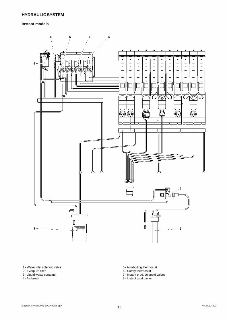
31© by NECTA VENDING SOLUTIONS SpA 07-2002 148 03
HYDRAULIC SYSTEM
Instant models
1 - Water inlet solenoid valve2 - Everpure filter3 - Liquid waste container4 - Air-break
5 - Anti-boiling thermostat6 - Safety thermostat7 - Instant prod. solenoid valves8 - Instant prod. boiler

© by NECTA VENDING SOLUTIONS SpA 07-2002 148 03
32
Fill
er m
enu
- Sum
mar
y
FILL
>1St
atis
tics
With
the
prin
ter c
onne
cted
prin
t all
data
as
disp
laye
dFI
LL>1
.1.1
.1Pa
rtial
prin
tout
FILL
>1.1
.1Pa
rtial
prin
tout
FILL
>1.1
.2To
tal p
rinto
ut
FILL
>1.1
Prin
t st
atis
tics
RE
LATI
VE ST
ATI
STI
CS
Prin
t dat
a by
:S
elec
tions
Tim
e ba
nds
Dis
coun
t/ove
rpric
eF
ailu
res
Coi
n m
echa
nism
dat
a
FILL
>1.1
.1.x
Parti
al p
rinto
utFI
LL>1
.1.1
.xPa
rtial
prin
tout
Con
firm
?Pr
intin
g
FILL
>1.1
.2To
tal p
rinto
utFI
LL>1
.1.2
Tota
l prin
tout
Conf
irm?
Prin
ting
Hea
ding
:C
urre
nt d
ate
Mac
hine
mod
elS
oftw
are
editi
onO
pera
tor
code
Mac
hine
cod
eIn
stal
latio
n da
te
Stat
istic
nam
e
FILL
>1.2
.1.1
Parti
al p
rinto
utFI
LL>1
.2.1
Parti
al p
rinto
ut
FILL
>1.2
.2To
tal p
rinto
ut
FILL
>1.2
Prin
t rel
ative
stat
istics
FILL
>1.2
.1.x
Parti
al p
rinto
utFI
LL>1
.2.1
.xPa
rtial
prin
tout
Conf
irm?
Prin
ting
FILL
>1.2
.2To
tal p
rinto
utFI
LL>1
.2.2
Tota
l prin
tout
Conf
irm?
Prin
ting
Stat
istic
nam
e
TO
TA
L S
TA
TIS
TIC
S
Prin
t da
ta b
y:S
elec
tions
Tim
e ba
nds
Dis
coun
t/ov
erpr
ice
Fai
lure
sC
oin
mec
hani
sm d
ata
FILL
>1.3
Disp
lay
stat
istics

© by NECTA VENDING SOLUTIONS SpA 07-2002 148 03
33
Fill
er m
enu
- Sum
mar
y
Dis
play
sal
es b
y si
ngle
sele
ctio
n fo
r eac
h tim
e ba
ndan
d to
tal
Dis
play
tota
l sal
es b
y si
ngle
sele
ctio
n
Dis
play
tota
l com
plet
e sa
les
in n
orm
al o
pera
tion
and
fille
rm
enu
mod
e
TO
TA
L S
TA
TIS
TIC
S
FILL
>1.3
Dis
play
sta
tistic
sFI
LL>1
.3.1
Dis
play
sel
. co
unte
rFI
LL>1
.3.1
.1D
ispla
y sin
gle c
ount
erFI
LL>1
.3.1
.1D
ispla
y sin
gle c
ount
erSe
lect
ion
1-#
FILL
>1.3
.1.1
Disp
lay s
ingl
e cou
nter
Sele
ctio
n 1-
#Ba
nd
# =
####
FILL
>1.3
.1.2
Dis
play
tot
al c
ount
erFI
LL>1
.3.1
.2D
ispl
ay t
otal
cou
nter
Sele
ctio
n 1-
#To
t. =
###
FILL
>1.3
.1.3
Dis
play
sel. c
ount
er n
.o.
Com
plet
e sel
. n.o
./mai
ntTo
t. =
###
FILL
>1.3
.1.3
Dis
play
sel. c
ount
er n
.o.
Val
ue o
f di
scou
nt a
ndo
verp
rice
FILL
>1.3
.3D
ispl
ay d
isco
unt
over
pric
e co
unte
r
FILL
>1.3
.3D
ispla
y disc
ount
coun
ter
Tot.
=
###
#
FILL
>1.3
.2D
ispl
ay c
ount
.by
time b
ands
FILL
>1.3
.2.x
Cou
nt.
by t
ime
band
sBa
nd
0÷4
Cou
nter
=
###
Val
ue o
f sal
es b
y tim
e ba
nd
FILL
>1.3
.3D
ispl
ay o
verp
rice
coun
ter
Tot.
=
###
#
FILL
>1.3
.4D
ispla
y fai
lure
s
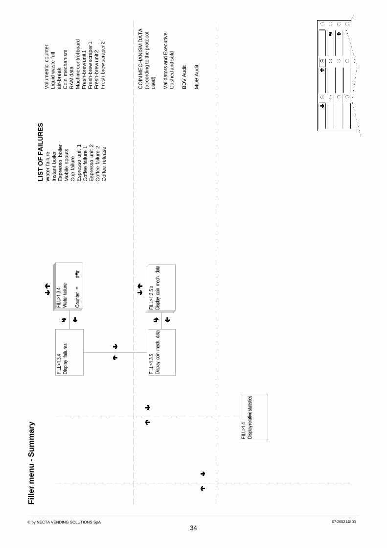
© by NECTA VENDING SOLUTIONS SpA 07-2002 148 03
34
Fill
er m
enu
- Sum
mar
yLI
ST
OF
FA
ILU
RE
SW
ater
fai
lure
Inst
ant
boile
rE
spre
sso
boile
rM
obile
spo
uts
Cup
fai
lure
Esp
ress
o un
it 1
Cof
fee
failu
re 1
Esp
ress
o un
it 2
Cof
fee
failu
re 2
Cof
fee
rele
ase
CO
IN M
EC
HA
NIS
M D
AT
A(a
ccor
ding
to th
e pr
otoc
olus
ed)
Val
idat
ors
and
Exe
cutiv
eC
ashe
d an
d so
ld
BD
V A
udit
MD
B A
udit
FILL
>1.3
.4D
ispl
ay f
ailu
res
FILL
>1.3
.4W
ater
failu
re
Cou
nter
=
###
FILL
>1.3
.5.x
Disp
lay c
oin m
ech.
dat
aFI
LL>1
.3.5
Disp
lay c
oin m
ech.
dat
a
FILL
>1.4
Disp
lay r
elat
ive st
atist
ics
Vol
umet
ric c
ount
erLi
quid
was
te fu
lla
ir-b
rea
kC
oin
mec
hani
smR
AM
dat
aM
achi
ne c
ontr
ol b
oard
Fre
sh-b
rew
uni
t 1F
resh
-bre
w s
crap
er 1
Fre
sh-b
rew
uni
t 2F
resh
-bre
w s
crap
er 2

© by NECTA VENDING SOLUTIONS SpA 07-2002 148 03
35
Fill
er m
enu
- Sum
mar
y
Dis
play
sal
es b
y si
ngle
sele
ctio
n fo
r eac
h tim
e ba
ndan
d to
tal
Dis
play
tota
l sal
es b
y si
ngle
sele
ctio
n
Dis
play
tota
l com
plet
e sa
les
in n
orm
al o
pera
tion
and
fille
rm
enu
mod
e
RE
LAT
IVE S
TA
TIS
TIC
S
FILL
>1.4
Disp
lay r
elat
ive st
atist
icsFI
LL>1
.4.1
Dis
play
sel
. co
unte
rFI
LL>1
.4.1
.1D
ispla
y sin
gle c
ount
erFI
LL>1
.4.1
.1D
ispla
y sin
gle c
ount
erSe
lect
ion
1-#
FILL
>1.4
.1.1
Disp
lay s
ingl
e cou
nter
Sele
ctio
n 1-
#Ba
nd
# =
####
FILL
>1.4
.1.2
Dis
play
tot
al c
ount
erFI
LL>1
.4.1
.2D
ispl
ay t
otal
cou
nter
Sele
ctio
n 1-
#To
t. =
###
FILL
>1.4
.1.3
Dis
play
sel. c
ount
er n
.o.
Com
plet
e sel
. n.o
./mai
ntTo
t. =
###
FILL
>1.4
.1.3
Dis
play
sel. c
ount
er n
.o.
Val
ue o
f dis
coun
t and
over
pric
e
FILL
>1.4
.3D
ispl
ay d
isco
unt
over
pric
e co
unte
r
FILL
>1.4
.3D
ispla
y disc
ount
coun
ter
Tot.
=
###
#
FILL
>1.4
.2C
ount
. by
tim
e ba
nds
FILL
>1.4
.2.x
Cou
nt.
by t
ime
band
sBa
nd
0÷4
Cou
nter
=
###
Val
ue o
f sal
es b
y tim
e ba
nd
FILL
>1.4
.3D
ispl
ay o
verp
rice
coun
ter
Tot.
=
###
#
FILL
>1.4
.4D
ispl
ay f
ailu
res

© by NECTA VENDING SOLUTIONS SpA 07-2002 148 03
36
Fill
er m
enu
- Sum
mar
y
LIS
T O
F F
AIL
UR
ES
Wat
er f
ailu
reIn
stan
t bo
iler
Esp
ress
o bo
iler
Mob
ile s
pout
sC
up f
ailu
reE
spre
sso
unit
1C
offe
e fa
ilure
1E
spre
sso
unit
2C
offe
e fa
ilure
2C
offe
e re
leas
e
CO
IN M
EC
HA
NIS
M D
AT
A(a
ccor
ding
to th
e pr
otoc
olus
ed)
Val
idat
ors
and
Exe
cutiv
eC
ashe
d an
d so
ld
BD
V A
udit
MD
B A
udit
FILL
>1.4
.4D
ispl
ay f
ailu
res
FILL
>1.4
.4W
ater
failu
re
Cou
nter
=
###
FILL
>1.4
.5.x
Disp
lay c
oin m
ech.
data
FILL
>1.4
.5D
ispla
y coi
n mec
h. da
ta
RE
LATI
VE ST
ATI
STI
CS
FILL
>1.5
.1.1
Parti
al d
elet
e
Sele
ctio
ns
FILL
>1.5
.2To
tal d
elet
e
FILL
>1.5
.1Pa
rtial
del
ete
FILL
>1.5
Del
ete r
elat
ivesta
tistic
s
Del
ete
data
by:
Sel
ectio
nsD
isco
unt/
over
pric
eF
ailu
res
Coi
n m
echa
nism
dat
a
Del
ete
all d
ata
RE
LATI
VE ST
ATI
STI
CS
FILL
>1.5
.1.1
Parti
al d
elet
eFI
LL>1
.5.1
.1Pa
rtial
del
ete
Conf
irm?
Wor
king
FILL
>1.5
.2.1
Tota
l del
ete
FILL
>1.5
.2.1
Tota
l del
ete
Conf
irm?
Wor
king
FILL
>2Pr
ices
Vol
umet
ric c
ount
erLi
quid
was
te fu
lla
ir-b
rea
kC
oin
mec
hani
smR
AM
dat
aM
achi
ne c
ontr
ol b
oard
Fre
sh-b
rew
uni
t 1F
resh
-bre
w s
crap
er 1
Fre
sh-b
rew
uni
t 2F
resh
-bre
w s
crap
er 2

© by NECTA VENDING SOLUTIONS SpA 07-2002 148 03
37
Fill
er m
enu
- Sum
mar
y
4 tim
e ba
nds
plus
ban
d 0
(no
time
band
set
) ava
ilabl
e w
ithdi
ffere
nt p
rices
for e
ach
sele
ctio
n
FILL
>2.1
Pric
eBa
nd
#
FILL
>2.1
.1Se
lect
ion
#
Band
#"
Pric
e##
##
FILL
>2.1
.1Se
lect
ion
#
Band
#"
Price
#
###
FILL
>2Si
ngle
price
s
FILL
>3BD
V/M
DB
Tube
cont
rol
FILL
>3.1
Fill t
ubes
Cre
dit:#
####
Man
ual c
hang
e tu
be r
efill
FILL
>3.2
Rel
ease
tube
s
Cre
dit:#
####
Man
ual t
ube
rele
asin
gFI
LL>3
.2Tu
be A
÷ X
Rel
ease
one
coi
n fr
om t
heac
tive
tube
FILL
>4.1
Boile
r te
mpe
ratu
res
I = #
##,#
C
=##
#,#
FILL
>4D
ispl
aybo
iler te
mpe
ratu
res
I =
Ins
tant
pro
d. b
oile
rC
= C
offe
e bo
iler
FILL
>5TE
ST

© by NECTA VENDING SOLUTIONS SpA 07-2002 148 03
38
Fill
er m
enu
- Sum
mar
y
Pre
ss t
he p
rogr
amm
ing
butto
n on
ceFI
LL>5
.1C
ompl
ete
sele
ctio
n
FILL
>5.2
Wat
er o
nly
FILL
>5.3
Pow
der o
nly
FILL
>5.2
Sele
ctbu
tton
#
FILL
>5.3
Sele
ctbu
tton
#
FILL
>5.4
Sele
ctbu
tton
#
FILL
>5.5
Sele
ctbu
tton
#
FILL
>5.5
Acce
ssor
ies o
nly
FILL
>5.1
Sele
ctbu
tton
#
FILL
>5.4
No a
cces
sorie
s
Pre
ss a
but
ton
tost
art d
ispe
nsin
g
FILL
>5TE
ST
FILL
>6G
SMFI
LL>6
.1R
eset
pr
e-al
arm
coun
ters
FILL
>6.1
Tota
l del
ete
FILL
>6.1
Tota
l del
ete
Conf
irm?
Wor
king
FILL
>7EV
ADTS
FILL
>7.1
Conn
ectio
n

© by NECTA VENDING SOLUTIONS SpA 07-2002 148 03
39
Tec
hnic
ian
men
u - S
umm
ary
Mon
itore
d fa
ilure
s:
Wat
er fa
ilure
Inst
ant b
oile
rE
spre
sso
boile
rM
obile
spo
uts
Cup
failu
reE
spre
sso
unit
1C
offe
e fa
ilure
1E
spre
sso
unit
2C
offe
e fa
ilure
2C
offe
e re
leas
eV
olum
etric
cou
nter
Liqu
id w
aste
full
Air-
brea
kC
oin
mec
hani
smR
AM
dat
aM
achi
ne c
ontr
ol b
oard
Fre
sh-b
rew
uni
t 1F
resh
-bre
w s
crap
er 1
Fre
sh-b
rew
uni
t 2F
resh
-bre
w s
crap
er 2
DIS
PLA
Y F
AIL
UR
ES
TEC
N >
1.2
Del
ete
failu
res
TEC
N >
1.2
Don
e
TEC
N >
1.1
End o
f failu
res
TEC
N >
1
Failu
res
Tim
e sc
rolli
ng o
fpr
esen
t fai
lure
sTE
CN
>1.
1
Rea
d Fa
ilure
s
TEC
N >
2Pr
ogra
mm
ing
para
met
ers

© by NECTA VENDING SOLUTIONS SpA 07-2002 148 03
40
Tec
hnic
ian
men
u - S
umm
ary
4 tim
e ba
nds
plus
ban
d 0
(no
time
band
set)
ava
ilabl
e w
ith d
iffer
ent
pric
es f
orea
ch s
elec
tion,
app
licab
le t
o th
e en
tire
wee
k or
onl
y to
som
e da
ys
X +
1
X - 1
TEC
N >
2.1.
1.2.
1Ba
nd 0
- 4
TEC
N >
2.1.
1.1
Sing
leSe
lect
ion
TEC
N >
2.1.
1.1.
1Ba
nd 0
- 4
TEC
N >
2.1.
1.1.
1Ba
nd
#Se
lect
but
ton
#
TEC
N >
2.1.
1.2.
1
Band
#
Pric
e##
##
TEC
N >
2.1.
1.1.
1Ba
nd #
"Se
lect
ion
#
Price
#
###
TEC
N >
2.1.
1.2
Glo
bal
sele
ctio
ns
TEC
N >
2.1.
1P
rices
TEC
N >
2Pr
ogra
mm
ing
para
met
ers
####
TEC
N >
2.1
Cas
h
TEC
N >
2.1.
1.3.
2Ti
me
band
1
Star
t ban
d
#
#En
d ba
nd #
# ##
CLO
CK
Whe
n co
nfirm
ing
the
blin
king
val
ues,
day,
mon
th,
year
and
wee
k da
y ar
een
tere
d on
e af
ter
the
othe
r. W
hen
conf
irmin
g th
e w
eek
day
hour
and
min
utes
are
dis
play
ed,
that
can
the
n be
chan
ged
and
conf
irmed
.
TIM
E BA
ND
S
Whe
n co
nfirm
ing
the
blin
king
val
ues,
hour
and
min
ute
for
star
t an
d en
d of
tim
eba
nd a
re e
nter
ed o
ne a
fter
the
othe
r.W
hen
star
t an
d en
d of
tim
e ba
nd a
re s
etto
24.
00 t
he b
ands
are
not
act
ivat
ed.
TEC
N >
2.1.
1.3
Tim
e ba
nds
TEC
N >
2.1.
1.3.
1Se
t dat
e an
d tim
e
TEC
N >
2.1.
1.3.
2Ti
me
band
1-
4##
TEC
N >
2.1.
1.3.
1Se
t dat
e an
d tim
e
Tim
e:
/#
#
TEC
N >
2.1.
1.3.
1Se
t dat
e an
d tim
e
Dat
e:
/##/
## d
d### ##

© by NECTA VENDING SOLUTIONS SpA 07-2002 148 03
41
Tec
hnic
ian
men
u - S
umm
ary
TEC
N >
2.1.
2C
oin
mec
hani
sms
AV
AIL
AB
LE C
OIN
ME
CH
AN
ISM
S
Val
idat
ors
Exe
cutiv
eB
DV
MD
B
TY
PE O
F V
EN
DIN
G
CH
AN
GE C
ON
TR
OL
TEC
N >
2.1.
2.1
Dis
pens
ing
type
TEC
N >
2.1.
2.1
Dis
pens
ing
type
TEC
N >
2.1.
2.1
Escr
ow ch
ange
leve
rTE
CN
>2.
1.2.
1Es
crow
chan
ge le
ver
TEC
N >
2.1.
2.1
Max
imum
cre
dit
TEC
N >
2.1.
2Se
t co
in m
echa
nism
s
TEC
N >
2.1.
2.1
Valid
ator
sLi
ne #
Valu
e##
##
AS A
LTE
RN
AT
IVE
BD
V/M
DBV
alid
ator
s
Exe
cutiv
e
A to
F
XXXX
+ 1
XXXX
- 1
SE
TT
ING
TH
E V
ALU
E O
F
VA
LID
AT
OR
LIN
ES
Sing
le/M
ultip
le
TEC
N >
2.1.
2.1
Valid
ator
sLi
ne #
ON
TEC
N >
2.1.
2.1
Exe
cutiv
e
Pr
otoc
ol n
ame
A E
nabl
e
D
Disa
ble
A
TEC
N >
2.1.
2.1
Set
coin
mec
hani
sms
"Coi
n mec
h. ty
pe "
EX
EC
UT
IVE
PR
OT
OC
OLS
Sta
ndar
dP
rice
Hol
ding
Cog
esU
Ke
yS
ida

© by NECTA VENDING SOLUTIONS SpA 07-2002 148 03
42
Tec
hnic
ian
men
u - S
umm
ary
XXXX
+ 1
XXXX
- 1
TEC
N >
2.1.
2.1
Max
imum
cre
dit
TEC
N >
2.1.
2.1
Valu
e =
####
###
##TE
CN
>2.
1.2.
1Va
lue
=
TEC
N >
2.1.
2.1
Valu
e =
Coi
ns 0
to
15
XXXX
+ 1
XXXX
- 1
TEC
N >
2.1.
2.1
Max
imum
cha
nge
TEC
N >
2.1.
2.1
Valu
e =
####
###
##
TEC
N >
2.1.
2.1
Acce
pted
coi
nsTE
CN
>2.
1.2.
1C
oin
0TE
CN
>2.
1.2.
1C
oin
0E
nabl
e
Dis
able
A DA
Coi
ns 0
to
15
TEC
N >
2.1.
2.1
Acce
pted
cha
nge c
oins
TEC
N >
2.1.
2.1
Coi
n 0
TEC
N >
2.1.
2.1
Coi
n 0
Ena
ble
Dis
able
A DA
TEC
N >
2.1.
2.1
Dis
pens
ing
butto
ns
TEC
N >
2.1.
2.1
Dis
pens
ing
butto
ns
Ena
ble
Dis
able
A DA
TEC
N >
2.1.
2.1
Eq. e
xact
chan
ge
Coi
n re
turn
tub
e re
leas
ebu
tton
s
MA
XIM
UM
CR
ED
IT
MA
XIM
UM
CH
AN
GE
AC
CE
PT
ED C
OIN
S
NO
T A
CC
EP
TE
D C
OIN
S
DIS
PE
NS
ING B
UT
TO
NS
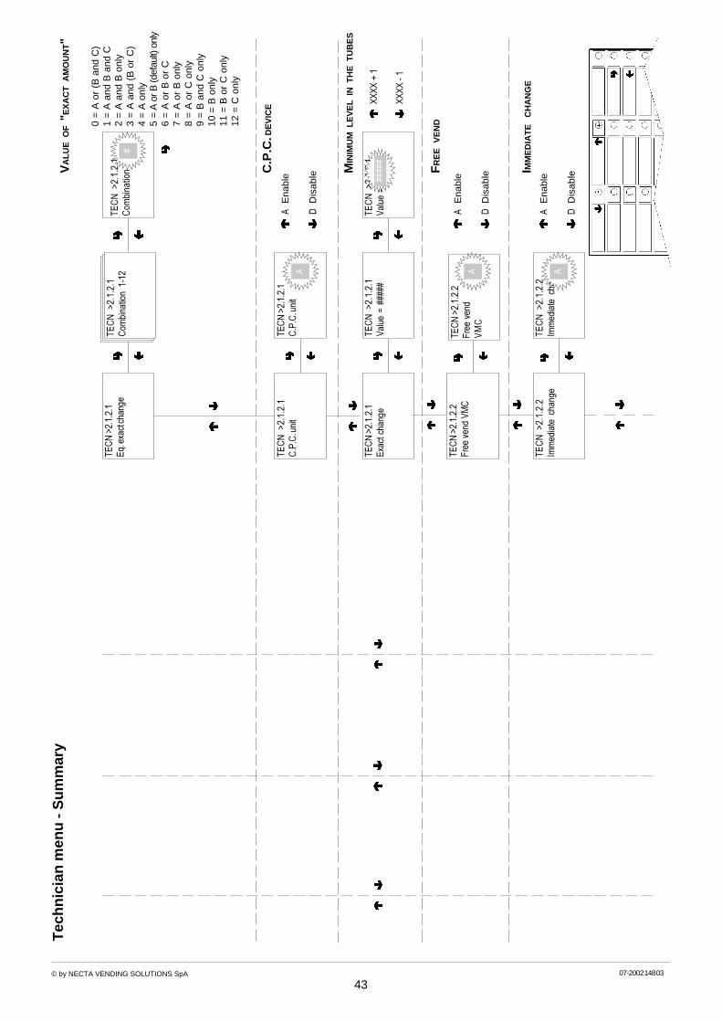
© by NECTA VENDING SOLUTIONS SpA 07-2002 148 03
43
Tec
hnic
ian
men
u - S
umm
ary
TEC
N >
2.1.
2.1
Eq. e
xact
chan
geTE
CN
>2.
1.2.
1C
ombi
natio
n 1-
12TE
CN
>2.
1.2.
1C
ombi
natio
n ####
TEC
N >
2.1.
2.1
Valu
e =
TEC
N >
2.1.
2.1
Valu
e =
####
#
TEC
N >
2.1.
2.1
C.P
.C. u
nit
TEC
N >
2.1.
2.1
C.P
.C. u
nit
TEC
N >
2.1.
2.1
Exac
t cha
nge
TEC
N >
2.1.
2.2
Imm
edia
te c
hang
e
Ena
ble
Dis
able
A D
XXXX
+ 1
XXXX
- 1
####
#
A
#
TEC
N >
2.1.
2.2
Imm
edia
te c
hang
e
Ena
ble
Dis
able
A D
0 =
A o
r (B
and
C)
1 =
A a
nd B
and
C2
= A
and
B o
nly
3 =
A a
nd (
B o
r C
)4
= A
onl
y5
= A
or B
(def
ault)
onl
y6
= A
or
B o
r C
7 =
A o
r B
onl
y8
= A
or
C o
nly
9 =
B a
nd C
onl
y10
= B
onl
y11
= B
or
C o
nly
12 =
C o
nly
TEC
N >
2.1.
2.2
Free
ven
d VM
CTE
CN
>2.
1.2.
2Fr
ee v
end
VM
C
Ena
ble
Dis
able
A DA
VA
LUE O
F "
EX
AC
T A
MO
UN
T"
C.P
.C. D
EV
ICE
MIN
IMU
M L
EV
EL IN
TH
E T
UB
ES
IMM
ED
IAT
E C
HA
NG
E
A
FR
EE V
EN
D

© by NECTA VENDING SOLUTIONS SpA 07-2002 148 03
44
Tec
hnic
ian
men
u - S
umm
ary
TEC
N >
2.1.
3D
ecim
al p
oint
TEC
N >
2.1.
3N
umbe
rof
dec
imal
s#
0 to
3
TEC
N >
2.1.
4C
urre
ncy/
Eur
o
TEC
N >
2.2
Sele
ctio
ns
DE
CIM
AL P
OIN
T

© by NECTA VENDING SOLUTIONS SpA 07-202 142-03
45
Tec
hnic
ian
men
u - S
umm
ary
TEC
N>2
.2.1
.2EV
set
tings
EV #
cc/
s =
##
Whe
n co
nfirm
ing,
100
cc o
f W
ater
dis
pens
ed
Ent
er w
eigh
ed v
alue
TEC
N>2
.2.1
.1Se
lect
ion
#
Wat
er "
Prod
uct n
ame"
Dos
e in
cc
TEC
N>2
.2.2
.2D
oser
setti
ngs
Dos
# g
/s =
XXX
+ 1
XXX
- 1
TEC
N>2
Sele
ctio
nsTE
CN
>2.2
.1Se
t w
ater
TEC
N>2
.2.1
.1Se
lect
but
ton
#
TEC
N>2
.2.1
.1Se
lect
ion
#
Wat
er "
Prod
uct n
ame"
Dos
e in
cc
###
###
TEC
N>2
.2.1
.2EV
set
tings
EV #
cc/
s =
###
TEC
N>2
.2.2
.2D
oser
setti
ngs
Dos
# g
/s =
###
###
TEC
N>2
.2.2
.1Se
lect
ion
#
Powd
er "
Prod
uct
nam
e"D
ose
in g
r
##
TEC
N>2
.2.2
.1Se
lect
ion
#
Powd
er "
Prod
uct
nam
e"
TEC
N>2
.2.2
.2D
oser
setti
ngs
Dos
1 ..
. g/
s =
##
TEC
N>2
.2.3
Acce
ssor
ies
Dis
pens
e?
TEC
N>2
.2.2
.2D
oser
setti
ngs
Dos
# g
/sD
ispe
nse?
TEC
N>2
.2.2
Set p
owde
r
TEC
N>2
.2.1
.1W
ater
dos
es
TEC
N>2
.2.1
.2EV
set
tings
TEC
N>2
.2.2
.1Po
wde
r dos
es
TEC
N>2
.2.2
.2D
oser
setti
ngs
TEC
N>2
.2.2
.1Se
lect
butto
n
#
TEC
N>2
.2.1
.2EV
set
tings
EV 1
- 9
cc/
s =
##
TEC
N>2
.2.2
.3G
loba
l pow
der
TEC
N>2
.2.2
.3G
loba
l?TE
CN
>2.2
.2.3
Powd
er "
Prod
uct
nam
e"D
ose
in g
###
TEC
N>2
.2.2
.3Si
ngle
?TE
CN
>2.2
.2.3
Sele
ctio
n
#Po
wder
"Pr
oduc
t na
me"
Dos
e in
g
#
#
TEC
N>2
.2.2
.3Se
lect
ion
#
Powd
er "
Prod
uct
nam
e"
TEC
N>2
.2.2
.3Se
lect
ion
#
Powd
er "
Prod
uct
nam
e"D
ose
in g
###
TEC
N>2
.2.2
.1Se
lect
ion
#
Powd
er "
Prod
uct
nam
e"D
ose
in g
r##
#

© by NECTA VENDING SOLUTIONS SpA 07-202 142-03
46
Tec
hnic
ian
men
u - S
umm
ary
Cup
Stir
rer
Sug
ar
AV
AIL
AB
LE AC
CE
SS
OR
IES
TEC
N>2
.2.3
Sele
ctio
n
# "
Acce
ssor
y na
me"
Enab
led/
disa
bled
TEC
N>2
.2.3
Sele
ctio
n
# "
Acce
ssor
y na
me"
Enab
led/
disa
bled
TEC
N>2
.2.4
Sele
ctio
n
#St
atus
Enab
led/
disa
bled
TEC
N>2
.2.4
Sele
ct b
utto
n #
TEC
N>2
.2.4
Sele
ctio
n st
atus
TEC
N>2
.2.5
Butto
n/se
lect
ion
com
bina
tion
TEC
N>2
.2.5
Butto
n 1 <
----->
Butto
n 2
TEC
N>2
.2.3
Acce
ssor
ies
TEC
N>2
.2.3
Sele
ct b
utto
n #
##
TEC
N>2
.2.4
Sele
ctio
n
#St
atus
Enab
led/
disa
bled
TEC
N>2
.3Ve
ndin
g m
achi
nepa
ram
eter
s
TEC
N>2
.3.1
Tem
pera
ture
TEC
N>2
.3.1
.1Es
pres
so b
oile
r
T. th
resh
old
= ##
#
TEC
N>2
.3.1
.2In
stan
t pro
d. b
oile
r
T. th
resh
old
= ##
#
TEC
N>2
.3.1
.2In
stan
t pro
d. b
oile
r
T. th
resh
old
=###
#
TEC
N>2
.3.1
.1Es
pres
so b
oile
r
T. th
resh
old
=####
TEC
N>2
.3.2
Enab
lew
ash
butto
n
TEC
N>2
.3.2
Stat
us Enab
led/
disa
bled
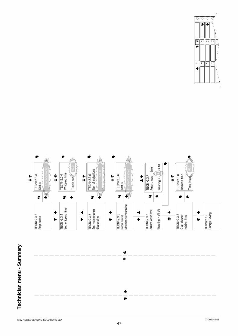
© by NECTA VENDING SOLUTIONS SpA 07-202 142-03
47
Tec
hnic
ian
men
u - S
umm
ary
TEC
N>2
.3.3
Stop
but
ton
TEC
N>2
.3.4
Set
whi
ppin
g tim
e
TEC
N>2
.3.5
Set
mai
nten
ance
disp
ensi
ng
TEC
N>2
.3.6
Neo
n st
atus
Mac
hine
out o
f ser
vice
TEC
N>2
.3.3
Stat
us Enab
led/
disa
bled
TEC
N>2
.3.8
Cup
sta
cker
rota
tion
time
TEC
N>2
.3.9
Ener
gy S
avin
g
TEC
N>2
.3.4
Whi
ppin
g tim
e
Tim
e in
sec.
02.0
TEC
N>2
.3.5
No.
of
sele
ctio
ns
0 ÷6
5.00
0
TEC
N>2
.3.6
Stat
us
Enab
led/
disa
bled
TEC
N>2
.3.8
Rot
atio
n tim
e
Tim
e in
sec.
02.0
TEC
N>2
.3.7
Auto
m. w
ash
time
Was
hing
= #
# ##
TEC
N>2
.3.7
Auto
m.
was
h t
ime
Was
hing
=
#
##
##

© by NECTA VENDING SOLUTIONS SpA 07-202 142-03
48
Tec
hnic
ian
men
u - S
umm
ary
EN
ER
GY S
AV
ING
Whe
n th
e bl
inki
ng v
alue
s ar
eco
nfirm
ed th
e ho
ur a
ndm
inut
es fo
r eac
h tim
e ba
ndst
art a
nd e
nd a
re e
nter
ed o
neaf
ter t
he o
ther
.If
star
t and
end
val
ues
are
set
to 0
0.00
the
time
band
s ar
edi
sact
ivat
ed.
TEC
N>2
.3.9
.2Ti
me
band
1÷
2TE
CN
>2.3
.9.2
Tim
e ba
nd
1St
art b
and
##
End
band
##
####
TEC
N>2
.3.9
.2D
ay
1÷
7
TEC
N>2
.3.9
Ener
gy s
avin
gTE
CN
>2.3
.9.1
Ener
gy s
avin
g
Enab
led/
disa
bled
TEC
N>2
.3.9
.1Bo
iler
switc
h of
f
Enab
led/
disa
bled
TEC
N>2
.4D
ispl
ay
Italia
nG
erm
an
Eng
lish
Fre
nch
Spa
nish
AV
AIL
AB
LE LA
NG
UG
ES
TEC
N>2
.4.1
Lang
uage
"La
ngua
ge n
ame"
TEC
N>2
.4.1
Lang
uage
Lang
uage
nam
e
TEC
N>2
.4.2
Prom
otio
nal m
essa
geTE
CN
>2.4
.2.1
Prom
otio
nal
mes
sage
Enab
led/
disa
bled
#TE
CN
>2.4
.2.2
Set m
essa
ge
TEC
N>2
.4.3
Cus
tom
ise m
essa
ges

© by NECTA VENDING SOLUTIONS SpA 07-202 142-03
49
Tec
hnic
ian
men
u - S
umm
ary
TEC
N>2
.4.3
Cus
tom
ise m
essa
ges
TEC
N>2
.4.3
Cus
tom
ise m
essa
ges
Enab
led/
disa
bled
TEC
N>2
.4.3
Set
mes
sage
Strin
g N
.:#
M
ESSA
GE
TEC
N>2
.5Pr
e-se
lect
ions
#
Le
tter s
crol
ling
Nex
t let
ter
Nex
t mes
sage
CH
AN
GE U
SE
R M
ES
SA
GE
TEC
N>2
.4.3
Set
mes
sage
Strin
g N
.:#
M
ESSA
GE
#
PR
E-S
ELE
CTI
ON
S
No
cup
Ext
ra s
ugar
Sug
arLe
ss s
ugar
Mor
e su
gar
Less
sug
arM
okka
Str
ong/
Ligh
tE
spre
sso
Cof
fee
pow
der
Jug
varia
tion
TEC
N>2
.5.1
Pre-
sele
ctio
ns
Pre-
sele
ctio
n na
me
TEC
N>2
.5.X
Pre-
sele
ctio
n n
ame
Stat
usEn
able
d/di
sabl
ed
TEC
N>2
.5.X
Pre-
sele
ctio
n na
me
Butto
n #
TEC
N>2
.5.X
Pre-
sele
ctio
n na
me
Pric
e ch
ange
Cha
nge
##
TEC
N>2
.5.X
Pre-
sele
ctio
n na
me
Dos
e ch
ange
Cha
nge
%##
TEC
N>2
.6M
isce
llane
ous

© by NECTA VENDING SOLUTIONS SpA 07-202 142-03
50
Tec
hnic
ian
men
u - S
umm
ary
TEC
N>2
.6M
isce
llane
ous
FR
ES
H B
RE
W U
NIT
S
Tw
o un
its c
an b
e in
stal
led
Par
amet
er s
ettin
gs:
Pre
-bre
win
g tim
eD
ryin
g tim
eW
hipp
ing
stat
usW
ash
stat
us
TEC
N>2
.6.1
Para
met
er n
ame
Stat
usEn
able
d/di
sabl
ed
TEC
N>2
.61
FB u
nit
1-#
Num
ber o
f fre
e co
nsec
utiv
ese
lect
ions
(1
to 9
)TE
CN
>2.6
Jug
faci
litie
sTE
CN
>2.6
Jug
faci
litie
s
Num
ber o
f sel
ectio
ns =
5
X +
1
X - 1
TEC
N>2
.6Ju
g fa
cilit
ies
Num
ber o
f sel
ectio
ns =#
TEC
N >
2.6.
4Fi
ller m
enu
mas
king
Men
u nam
eTE
CN
>2.
6.4.
X
Fille
r m
enu
Enab
led/
disa
bled
Enab
led
Dis
able
d
TEC
N >
2.6.
4.X
Men
u na
me
Fille
r m
enu
Enab
led/
disa
bled
Sta
tistic
sP
rice
sB
DV
tub
e co
ntro
lB
oile
r te
mpe
tatu
reT
est
GS
M
FIL
LER
ME
NU M
AS
KE
D
TEC
N >
2.6.
5Cu
stom
. sel
ectio
ns
PRO
G>2
.6.3
.1St
atus
Fiv
e-di
git n
umbe
r to
acce
sspr
ogra
mm
ing.
If se
t to
Zer
o (d
efau
lt) th
epa
ssw
ord
is n
ot re
ques
ted
PRO
G>2
.6.3
Pass
wor
d
Enab
led/
disa
bled
PRO
G>2
.6.3
.2Se
t pas
swor
d
Pass
wor
d =
#
###
X +
1
X - 1
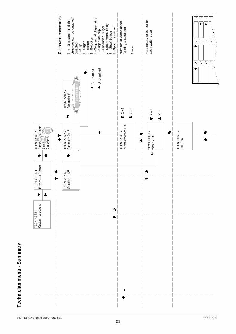
© by NECTA VENDING SOLUTIONS SpA 07-202 142-03
51
Tec
hnic
ian
men
u - S
umm
ary
The
10
para
met
er o
f th
est
ruct
ure
can
be e
nabl
ed/
disa
bled
:0
-Cup
1 -S
ugar
2 -S
tirre
r3
-Sel
ectio
n4
-Seq
uenc
ial
disp
ensi
ng5
-Sug
ar in
to c
up6
-Pre
-mix
ed s
ugar
7 -S
pout
ret
urn
dela
y8
-"S
top"
but
ton
9 -S
pout
mov
emen
t
TEC
N >
2.6.
5.2
N. o
f wat
er d
oses
1÷4
TEC
N >
2.6.
5.2
Sele
ctio
n 1
÷28
TEC
N >
2.6.
5.2
Wat
er N
. #
TEC
N >
2.6.
5.2
Uni
t 1÷
8
TEC
N >
2.6.
5C
usto
m.
sele
ctio
ns
X +
1
X - 1
TEC
N >
2.6.
5.2
Para
met
er 0
÷15
Ena
bled
Dis
able
d
A D
CU
ST
OM
ISE C
OM
PO
SIT
ION
TEC
N >
2.6.
5.2
Para
met
er #
Num
ber
of w
ater
dos
esfo
rmin
g a
sele
ctio
n
1 to
4
X +
1
X - 1
Par
amet
ers
to b
e se
t fo
rea
ch w
ater
dos
e.
Enab
led/
disa
bled
TEC
N >
2.6.
5.1
Butto
n<---
->C
usto
m.
Butto
nC
usto
m N
.
TEC
N >
2.6.
5.1
Butto
n<---
->C
usto
m.
####

© by NECTA VENDING SOLUTIONS SpA 07-2002 148 03
52
Tec
hnic
ian
men
u - S
umm
ary
FUN
CTI
ON
AL UN
IT
TEC
H>2
.6.5
.2N
ame
0 ÷
15
TEC
H>2
.6.5
.2So
leno
id v
alve
1 ÷
9
TEC
H>2
.6.5
.2U
nit
1 ÷
8
TEC
H>2
.6.5
.2W
ater
N.
#
Wat
er d
ispe
nsin
g m
etho
d
.N
tin
U1
)HL(
1tnatsnI
2)
HR(
2tnatsnI
3)
HL(1
osserpsE
4)
HR(
2osserps
E
5)
HL(1
werbhserF
6)
HR(
2werb
hserF
7re
werbaeT
8tinu
dloC
X +
1
X - 1
X +
1
X - 1
.N
ema
N0
eeffoC
1ragu
S
2kli
M
3etalocoh
C
4aeT
5puo
S
6detaniefface
D
7pury
S
8eeffoctnatsnI
9wer
B-hserF
01no
meL
11tnatsnI
21dlo
C
31 41 51

© by NECTA VENDING SOLUTIONS SpA 07-2002 148 03
53
Tec
hnic
ian
men
u - S
umm
ary
SE
TT
ING L
AY
OU
T O
F U
SE
RS
TEC
H>2
.6.5
.2W
hipp
er
1 ÷
11
TEC
H>2
.6.5
.2So
leno
id v
alve
1 ÷
9
TEC
H>2
.6.5
.2N
ame
0 ÷
15
tin
ulan
oitcn
uF
VE
tnatsnIwerb-hserFre
werbaeT
osserpsE
tinudlo
C
1reliobtnatsni
1eeffoc
gnisnepsid1
redwop
retaw
2reliobtnatsni
2eeffoc
gnisnepsidreta
wnialp
3reliobtnatsni
2red
wopreta
w
4reliobtnatsni
ados
8÷5
reliobtnatsni
9sledo
meseht
rofelbacilppaton
####
TEC
H>2
.6.5
.2W
ater
dos
eTE
CH
>2.6
.5.2
Wat
er d
ose
###
#XX
XX +
1
XXXX
- 1
####
#
TEC
H>2
.6.5
.2Po
wde
r N
. 1
÷ 4
X +
1
X - 1 X +
1
X - 1

© by NECTA VENDING SOLUTIONS SpA 07-2002 148 03
54
Tec
hnic
ian
men
u - S
umm
ary
TEC
H>2
.6.5
.2W
ater
dos
e #
###
TEC
H>2
.6.5
.2Po
wde
r N
. 1
÷4
TEC
H>2
.6.5
.2Ty
pe 1
÷ 4
TEC
H>2
.6.5
.2N
ame
0 ÷
15
.N
gnis
nepsi
D1
suounitnoc
2deppets
3eeffoc
tnatsni
4ragus
TEC
H>2
.6.5
.2Po
wde
r N
. #
X +
1
X - 1
Num
ber
of p
owde
r do
ses
assi
gned
to
a w
ater
dos
e.
1 to
4
Par
amet
ers
to b
e se
t fo
rea
ch p
owde
r do
seX
+ 1
X - 1
X +
1
X - 1

© by NECTA VENDING SOLUTIONS SpA 07-2002 148 03
55
Tec
hnic
ian
men
u - S
umm
ary
TEC
H>2
.6.5
.2D
oser
dev
ice
1÷13
X +
1
X - 1
TEC
H>2
.6.5
.2Po
wde
r de
lay
####
TEC
H>2
.6.5
.2N
ame
0 ÷
15
TEC
H>2
.6.5
.2Ty
pe 1
÷ 4
X +
1
X - 1
.N
ema
N0
eeffoC
1ragu
S
2kli
M
3etalocoh
C
4aeT
5puo
S
6detaniefface
D
7pury
S
8eeffoctnatsnI
9wer
B-hserF
01no
meL
11tnatsnI
21dlo
C
31 41 51
WA
RN
ING!
If th
e po
wde
r na
me
isde
fined
as
"syr
up",
dos
er 1
and
2 w
ill c
orre
spon
d to
the
syru
p di
spen
sing
dev
ices
.

© by NECTA VENDING SOLUTIONS SpA 07-2002 148 03
56
Tec
hnic
ian
men
u - S
umm
ary
TEC
H>2
.6.5
.2D
oser
dev
ice
1÷13
TEC
H>2
.6.5
.2Po
wde
r del
ay
Tim
e in
sec.
XXXX
+ 1
XXXX
- 1
####
#
####
TEC
H>2
.6.5
.2Po
wde
r dos
eTE
CH
>2.6
.5.2
Pow
der d
ose
###
#XX
XX +
1
XXXX
- 1
####
#
TEC
H>2
.6.5
.2Po
wde
r N
. 1÷4
TEC
H>2
.6.6
EVAD
TS

© by NECTA VENDING SOLUTIONS SpA 07-2002 148 03
57
Tec
hnic
ian
men
u - S
umm
ary
MA
CH
INE
IDE
NT
IFIC
AT
ION C
OD
E
Whe
n pr
essi
ng th
e ch
ange
butto
n th
e fir
st d
igit
stra
tsbl
inki
ng.
Whe
n pr
essi
ng a
but
ton,
the
blin
king
dig
it w
ill ta
ke o
n th
atva
lue
and
the
next
dig
it st
arts
blin
king
.
TEC
H>2
.6.6
EVAD
TSTE
CH
>2.6
.6.1
Pass
cod
e
Pass
000
0
TEC
H>2
.6.6
.1Pa
ss c
ode
Cod
e 0
00X
X +
1
X - 1
TEC
H>2
.6.6
.2Se
curit
y co
de
Secu
rity
000
0
TEC
H>2
.6.6
.2Se
curit
y co
de
Cod
e 0
00X
X +
1
X - 1
TEC
H>3
STAT
ISTI
CS
TEC
H>2
.6.6
.3Co
nnec
tion
TEC
H>2
.6.6
.3Co
nnec
tion
Wai
t ple
ase

© by NECTA VENDING SOLUTIONS SpA 07-2002 148 02
58
Tec
hnic
ian
men
u - S
umm
ary
Dis
play
sal
es b
y si
ngle
sele
ctio
n fo
r eac
h tim
e ba
ndan
d to
tal
Dis
play
tota
l sal
es b
y si
ngle
sele
ctio
n
Dis
play
tota
l com
plet
e sa
les
in n
orm
al o
pera
tion
and
fille
rm
enu
mod
e
TO
TA
L S
TA
TIS
TIC
S
TEC
H>3
STAT
ISTI
CS
TEC
H>3
.1.1
Dis
play
sel
. co
unte
rTE
CH
>3.1
.1.1
Disp
lay s
ingle
coun
ter
TEC
H>3
.1.1
.1Di
splay
sing
le co
unte
rSe
lect
ion
1-#
TEC
H>3
.1.1
.1Di
splay
sing
le co
unte
rSe
lect
ion
1-#
Band
#
= ##
##
TEC
H>3
.1.1
.2D
ispl
ay t
otal
cou
nter
TEC
H>3
.1.1
.2D
ispl
ay t
otal
cou
nter
Sele
ctio
n 1-
#To
t. =
###
TEC
H>3
.1.1
.3Di
splay
sel.
cou
nter
n.o
.Co
mple
te s
el. n
.o/m
aint
Tot.
= ##
#
TEC
H>3
.1.1
.3Di
splay
sel.
cou
nter
n.o
.
TEC
H>3
.1D
ispl
ay s
tatis
tics
TEC
H>3
.1.3
Dis
play
dis
coun
tov
erpr
ice
coun
ter
TEC
H>3
.3.3
.1D
ispl
ay d
isco
unt
cou
nte
rTo
t. =
#
###
TEC
H>3
.1.2
Cou
nt.
by t
ime
band
sTE
CH
>3.1
.2.1
Cou
nt.
by t
ime
band
sBa
nd
0÷4
Cou
nter
=
###
TEC
H>3
.3.3
.1D
ispl
ay o
verp
rice
cou
nter
Tot.
=
###
#
TEC
H>3
.3.4
Dis
play
fai
lure
s
Val
ue o
f sal
es b
y tim
e ba
nd
Val
ue o
f dis
coun
t and
over
pric
e

© by NECTA VENDING SOLUTIONS SpA 07-2002 148 02
59
Tec
hnic
ian
men
u - S
umm
ary
TEC
H>3
.3.4
Dis
play
fai
lure
sTE
CH
>3.3
.4W
ater
failu
re
Cou
nter
=
###
TEC
H>3
.3.5
.xDi
splay
coin
mec
h. d
ata
TEC
H>3
.3.5
Disp
lay c
oin m
ech.
dat
a
TEC
H>3
.2.1
Parti
al d
elet
e
Sele
ctio
ns
TEC
H>3
.2.2
Tota
l del
ete
TEC
H>3
.2.1
Parti
al d
elet
eTE
CH
>3.2
Del
ete
stat
istic
sTE
CH
>3.2
.1Pa
rtial
del
ete
TEC
H>3
.2.1
Parti
al d
elet
e
Conf
irm?
Wor
king
TEC
H>3
.2.2
Tota
l del
ete
TEC
H>3
.2.2
Tota
l del
ete
Conf
irm?
Wor
king
Del
ete
data
by:
Sel
ectio
nsD
isco
unt/
over
pric
eF
ailu
res
Coi
n m
echa
nism
dat
a
Del
ete
all d
ata
LIS
T O
F F
AIL
UR
ES
Wat
er f
ailu
reIn
stan
t bo
iler
Esp
ress
o bo
iler
Mob
ile s
pout
sC
up f
ailu
reE
spre
sso
unit
1C
offe
e fa
ilure
1E
spre
sso
unit
2C
offe
e fa
ilure
2C
offe
e re
leas
e
Vol
umet
ric c
ount
erLi
quid
was
te fu
lla
ir-b
rea
kC
oin
mec
hani
smR
AM
dat
aM
achi
ne c
ontr
ol b
oard
Fre
sh-b
rew
uni
t 1F
resh
-bre
w s
crap
er 1
Fre
sh-b
rew
uni
t 2F
resh
-bre
w s
crap
er 2
TEC
H>3
.3D
ispl
ay r
elat
ive
sta
tistic
s
CO
IN M
EC
HA
NIS
M D
AT
A
(acc
ordi
ng to
the
prot
ocol
used
)
Val
idat
ors
and
Exe
cutiv
eC
ashe
d an
d so
ld
BD
V A
udit
MD
B A
udit
CA
NC
ELL
AZ
ION
E T
OT
AL
ST
AT
IST
ICS

© by NECTA VENDING SOLUTIONS SpA 07-2002 148 02
60
Tec
hnic
ian
men
u - S
umm
ary
TEC
H>3
.4D
elet
e re
lativ
e s
tatis
tics
TEC
H>3
.4.1
.1Pa
rtial
del
ete
Sele
ctio
ns
TEC
H>3
.4.2
Tota
l del
ete
TEC
H>3
.4.1
Parti
al d
elet
e
Del
ete
data
by:
Sel
ectio
nsD
isco
unt/
over
pric
eF
ailu
res
Coi
n m
echa
nism
dat
a
Del
ete
all d
ata
TEC
H>3
.4.1
.1Pa
rtial
del
ete
TEC
H>3
.4.1
.1Pa
rtial
del
ete
Conf
irm?
Wor
king
TEC
H>3
.4.2
.1To
tal d
elet
eTE
CH
>3.4
.2.1
Tota
l del
ete
Conf
irm?
Wor
king
Dis
play
sal
es b
y si
ngle
sele
ctio
n fo
r eac
h tim
e ba
ndan
d to
tal
Dis
play
tota
l sal
es b
y si
ngle
sele
ctio
n
RE
LAT
IVE S
TA
TIS
TIC
S
TEC
H>3
.3D
ispl
ay r
elat
ive
sta
tistic
s
DE
LET
E R
ELA
TIV
E
ST
AT
IST
ICS
TEC
H>3
.1.1
Dis
play
sel
. co
unte
rTE
CH
>3.1
.1.1
Disp
lay s
ingl
e cou
nter
TEC
H>3
.1.1
.1D
ispla
y sin
gle c
ount
erSe
lect
ion
1-#
TEC
H>3
.1.1
.1D
ispla
y sin
gle c
ount
erSe
lect
ion
1-#
Band
#
= ##
##
TEC
H>3
.1.1
.2D
ispl
ay t
otal
cou
nter
TEC
H>3
.1.1
.2D
ispl
ay t
otal
cou
nter
Sele
ctio
n 1-
#To
t. =
###
TEC
H>3
.1.1
.3D
ispl
ay se
l. cou
nter
n.o
.C
ompl
ete s
el. n
.o./m
aint
Tot.
= ##
#
TEC
H>3
.1.1
.3D
ispl
ay se
l. cou
nter
n.o
.
Dis
play
tota
l com
plet
e sa
les
in n
orm
al o
pera
tion
and
fille
rm
enu
mod
e
Dis
play
dat
a fo
r:S
elec
tions
Dis
coun
t/ov
erpr
ice
Fai
lure
sC
oin
mec
hani
sm d
ata
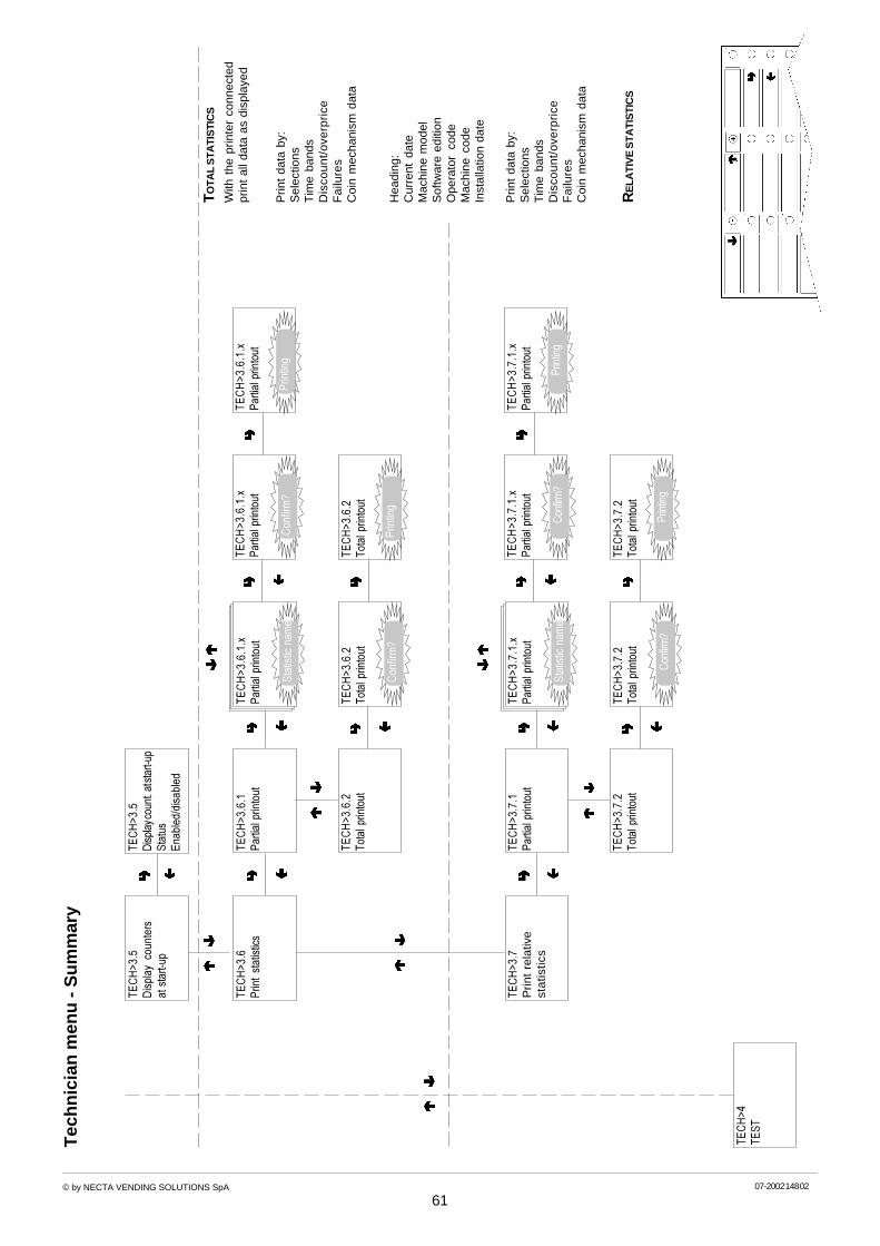
© by NECTA VENDING SOLUTIONS SpA 07-2002 148 02
61
Tec
hnic
ian
men
u - S
umm
ary
TEC
H>3
.5D
ispla
y cou
nt. a
t sta
rt-up
Stat
usEn
able
d/di
sabl
ed
TEC
H>3
.5D
ispl
ay c
ount
ers
at s
tart-
up
With
the
prin
ter
conn
ecte
dpr
int
all d
ata
as d
ispl
ayed
TEC
H>3
.6.1
.xPa
rtial
prin
tout
TEC
H>3
.6.1
Parti
al p
rinto
ut
TEC
H>3
.6.2
Tota
l prin
tout
TEC
H>3
.6Pr
int
stat
istic
s
RE
LATI
VE ST
ATI
STI
CS
Prin
t da
ta b
y:S
elec
tions
Tim
e ba
nds
Dis
coun
t/ov
erpr
ice
Fai
lure
sC
oin
mec
hani
sm d
ata
TEC
H>3
.6.1
.xPa
rtial
prin
tout
TEC
H>3
.6.1
.xPa
rtial
prin
tout
Con
firm
?Pr
intin
g
TEC
H>3
.6.2
Tota
l prin
tout
TEC
H>3
.6.2
Tota
l prin
tout
Con
firm
?Pr
intin
gH
eadi
ng:
Cur
rent
dat
eM
achi
ne m
odel
Sof
twar
e ed
ition
Ope
rato
r co
deM
achi
ne c
ode
Inst
alla
tion
date
Stat
istic
nam
e
TEC
H>3
.7.1
.xPa
rtial
prin
tout
TEC
H>3
.7.1
Parti
al p
rinto
ut
TEC
H>3
.7.2
Tota
l prin
tout
TEC
H>3
.7P
rint
rela
tive
sta
tistic
s
TEC
H>3
.7.1
.xPa
rtial
prin
tout
TEC
H>3
.7.1
.xPa
rtial
prin
tout
Conf
irm?
Prin
ting
TEC
H>3
.7.2
Tota
l prin
tout
TEC
H>3
.7.2
Tota
l prin
tout
Conf
irm?
Prin
ting
Stat
istic
nam
e
TOTA
L ST
ATI
STI
CS
Prin
t da
ta b
y:S
elec
tions
Tim
e ba
nds
Dis
coun
t/ov
erpr
ice
Fai
lure
sC
oin
mec
hani
sm d
ata
TEC
H>4
TEST

© by NECTA VENDING SOLUTIONS SpA 07-2002 148 02
62
Tec
hnic
ian
men
u - S
umm
ary
TEC
H>4
TEST
TEC
H>4
.1C
ompl
ete
sele
ctio
nTE
CH
>4.1
Sele
ctbu
tton
#P
ress
a b
utto
n to
sta
rtdi
spen
sing
FR
ES
H B
RE
W U
NIT
S
Tw
o un
its c
an b
e in
stal
led
Par
amet
er s
ettin
gs:
Pre
-bre
win
g tim
eD
ryin
g tim
eW
hipp
ing
stat
usW
ash
stat
us
TEC
H>4
.2.1
Para
met
er n
ame
Stat
usEn
able
d/di
sabl
ed
TEC
H>4
.2.1
FB u
nit 1
-#TE
CH
>4.2
Uni
t co
ntro
l
TEC
H>4
.3.1
Auto
test C
onfir
m?
TEC
H>4
.3Au
tote
stA
ctua
tion
in a
seq
uenc
e of
:.d
oser
dev
ices
.mix
ers
.cup
dis
pens
er.s
trirr
er d
ispe
nser
.neo
n (f
luor
esce
nt)
lam
ps.d
oor
LED
.pus
h-bu
tton
s*.m
obile
spo
uts
.cof
fee
dose
.uni
t ro
tatio
n.li
quid
was
te fu
ll*
* th
ese
func
tions
req
uire
the
assi
stan
ce o
f th
e us
erto
trip
the
sw
itche
s .
TEC
H>4
.3.1
.xFu
nctio
n na
me
Plea
se w
ait
TEC
H>4
.3.1
Test
tast
iera
Butto
n N
. __
TEC
H>4
.3.1
Liqu
id w
aste
ful
l
Trip
micr
osw
itch
TEC
H>5
VAR
IE

© by NECTA VENDING SOLUTIONS SpA 07-2002 148 02
63
Tec
hnic
ian
men
u - S
umm
ary
TEC
H>5
MIS
CEL
LAN
EOU
S
TEC
H>5
.2.1
Wor
king
TEC
H>5
.2.1
Con
firm
?
TEC
H>5
.2In
itialis
e D
B S
TAR
T
TEC
H>5
.1.2
Mac
hine
cod
eTE
CH
>5.1
.2M
achi
ne c
ode
Cod
e =
####
# #
TEC
H>5
.1.1
Inst
alla
tion
date
Dat
e =
XX
.XX.
XX
TEC
H>5
.1.1
Inst
alla
tion
date
Con
firm
?
TEC
H>5
.1.3
Ope
rato
r co
deTE
CH
>5.1
.3O
pera
tor
code
Cod
e =
####
# #
TEC
H>5
.1Ve
ndin
g m
achi
ne i
nfo
TEC
H>6
GSM
TEC
H>6
.2.2
Res
et p
re-a
larm
coun
ters
TEC
H>6
.3.1
Tota
l del
ete
TEC
H>6
.3.1
Tota
l del
ete
Con
firm
?W
orki
ng
TEC
H>1
Failu
res
TEC
H>6
.2Se
t th
resh
olds
TEC
H>6
.1PI
NTE
CH
>6.1
.1PI
N
Pin=
##
###
#
TEC
H>6
.2.1
Set
thre
shol
dsPr
oduc
t n
ame
N. o
r g.
= #
##
TEC
H>6
.2.1
Parti
al p
rinto
ut
N. o
r g.
= ##
TEC
H>6
.2.1
Set
thre
shol
ds
Prod
uct n
ame
#
X +
1
X - 1

© by NECTA VENDING SOLUTIONS SpA 0202 142-02
INITIALS DESCRIPTION
WIRING DIAGRAM LEGEND
INITIALS DESCRIPTION
64
BDV BDV COIN MECH CONNECTORS
CCG GENERAL COUNTER
CM1 COFFEE UNIT MOTOR CAM
CM2 COFFEE DISPENSING POSITION CAM
CMF FRESH BREW MOTOR CAM
CMPF FRESH BREW UNIT PISTON MICROSWITCH
CMSB CUP RELEASE MOTOR CAM
CV VOLUMETRIC COUNTER
EEA WATER INLET SOLENOID VALVE
ER COFFEE DISPENSER SOLENOID VALVE
ESC COFFEE RELEASE MAGNET
EV SANITISING KIT SOLENOID VALVE
EX EXECUTIVE COIN MECH CONNECTOR
FA RADIO INTERFERENCE SUPPRESSOR
FREE FREE VENDING SWITCH
I SANITISING KIT SWITCH
ID COFFEE DOSE SWITCH
IMSP STIRRER RELEASE MICROSWITCH
IP DOOR SWITCH
IPF WASTE CONTAINER OVERFLOW SWITCH
IVA EMPTY BOILER MICROSWITCH
IVB EMPTY CUP DISPENSER MICROSWITCH
IVP EMPTY STIRRER DISPENSER MICROSWITCH
JUG JUG FACILITIES SWITCH
KC1-.. COFFEE BOILER CUTOUT
KS1-.. SAFETY CUTOUT
LF LAMP
M COFFEE UNIT MOTOR
MAC GRINDER
MD1-.. DOSER DEVICES - INSTANT
MDB CONNECTOR FOR MDB COIN MECHANISM
MDFB DOSER DEVICE - FRESH BREW
MDZ DOSER DEVICE - SUGAR
MF1-.. WHIPPERS - INSTANT
MFB FRESH-BREW MOTOR
MPF PRESH BREW PISTON MOTOR
MPU SPOUT POSITIONING MICROSWITCH
MSB CUP RELEASE MOTOR
MSCB CUP CONTAINER SHIFT MOTOR
MSP STIRRER RELEASE MOTOR
MSU SPOUT MOVING MOTOR
MVP EMPTY STIRRER DISPENSER MOTOR
NTC1-. TEMPERATURE PROBE
NTCS INSTANT BOILER TEMPERATURE PROBE
PAG FAILURE RESET BUTTON
PB POWER SUPPLY SOCKET
PD DIODE RECTIFIER
PG UNIT DETECTION MICROSWITCH
PIP PROGRAMMING BUTTON
PM PUMP
PSB CUP RELEASE BUTTON
RCC COFFEE BOILER HEATING ELEMENT
RG UNIT HEATING ELEMENT
RS232 SERIAL PORT
RT BALLAST
SAL VOLTAGE SUPPLY CARD
SLCD LIQUID CRYSTAL DISPLAY CARD
SLED LED BOARD
SM1 CONTROL BOARD
SM2 EXPANSION BOARD
SP PUSH-BUTTON BOARD
ST STARTER
STRC BOILER HEATING TRIAC BOARD
SUC C.P.U. BOARD
TR TRANSFORMER
TX.... DELAYED FUSE (X=COURRENT)
TZ CUP SENSOR
UPS COLD UNIT PRINTED BOARD
VENT FAN

© by NECTA VENDING SOLUTIONS SpA NOTE

sx34800
NECTA VENDING SOLUTIONS SpA

Zenith

NECTA VENDING SOLUTIONS SpA
Sx34900

Zenith

NECTA VENDING SOLUTIONS SpA
sx35001

Zenith

© by NECTA VENDING SOLUTIONS SpA NOTE

© by NECTA VENDING SOLUTIONS SpA NOTE

© by NECTA VENDING SOLUTIONS SpA NOTE

The Manufacturer reserves the right to modify, without prior notice, the characteristics of the equipment described inthis publication; and further declines to accept any responsibility for any inaccuracies contained in this publicationwhich can be ascribed to printing and/or transcription errors.All instructions, drawings, tables and information contained in this publication are confidential and can neither bereproduced completely nor in part, nor be transmitted to third parties without the written permit of the Manufacturer, whohas the sole ownership.
EDITION 07-2002 CODE: H 148U 03 PER APPROVAZIONEIl Responsabile