z80380 cpu user s m - grauwmap.grauw.nl/resources/cpu/z380um.pdf1-3 z380 zilog user's manual...
TRANSCRIPT

DC-8297-03
PREFACE
Thank you for your interest in the Z380™ Central Processing Unit (CPU) and itsassociated family of products. This Technical Manual describes programmingand operation of the Z380™ Superintegration™ Core CPU, which is found in theZ380 Microprocessor Unit (MPU), and products built around Z380™ CPU core.
This Z380 User's Manual consists of the following Sections:
1. Z380™ Architectural OverviewChapter 1 is an introductory section covering the key features andgiving an overview of the architecture of the device.
2. Address SpacesChapter 2 explains the address spaces the Z380 CPU can handle.Also, this chapter includes a brief description of the on-chip regis-ters.
3. Native/Extended Mode, Word/Long Word Mode of Operation,and Decoder DirectivesThis chapter provides a detailed explanation on the Z380’s uniquefeatures, operation modes, and the Decoder Directives.
4. Addressing Modes and Data TypesChapter 4 describes the Addressing mode and data types which theZ380 can handle.
5. Instruction SetChapter 5 contains an overview of the instruction set; as well as adetailed instruction-by-instruction description in alphabetical order.
6. Interrupts and TrapsChapter 6 explains the interrupts and traps features of the Z380.
7. ResetChapter 7 describes the Reset function.
8. Z380 Benchmark Appnote
9. Z380 Questions & Answers
Z80380 CPUUSER'S MANUAL

ZILOG
DC-8297-03
Appendix AAppendix A covers the Z380’s instruction format.
Appendix BAppendix B contains all Z380 instructions sorted in AlphabeticalOrder.
Appendix CAppendix C contains all Z380 instructions sorted in NumericalOrder.
Appendix DThe Tables in Appendix D lists all the Z380 instructions in instructionaffected by Native/Extended mode and Word/Long Word mode.
Appendix EThe Tables in Appendix E lists all the Z380 instructions in instructionaffected by DDIR IM (Immediate Decoder Directives) mode.
IndexA to Z listing of Z380™ User's Manual key words and phrases.
This manual assumes the reader has a basic knowledge of CPU-based system architectures and software development systems,such as the use of the text editor, and invoking the assembler/compiler. Also, knowledge of the Z80® CPU architecture is desirable.
Zilog’s products are not authorized for use as critical compo-nents in life support devices or systems unless a specific writtenagreement pertaining to such intended use is executed betweenthe customer and Zilog prior to use. Life support devices orsystems are those which are intended for surgical implantationinto the body, or which sustains life whose failure to perform,when properly used in accordance with instructions for useprovided in the labeling, can be reasonably expected to result insignificant injury to the user.
Zilog, Inc. 210 East Hacienda Ave.Campbell, CA 95008-6600Telephone (408) 370-8000Telex 910-338-7621FAX 408 370-8056Internet: http://www.zilog.com
© 1994, 1995, 1996, 1997 by Zilog, Inc. All rights reserved. Nopart of this document may be copied or reproduced in any formor by any means without the prior written consent of Zilog, Inc.The information in this document is subject to change withoutnotice. Devices sold by Zilog, Inc. are covered by warranty andpatent indemnification provisions appearing in Zilog, Inc. Termsand Conditions of Sale only.
ZILOG, INC. MAKES NO WARRANTY, EXPRESS, STATUTORY,IMPLIED OR BY DESCRIPTION, REGARDING THE INFORMA-TION SET FORTH HEREIN OR REGARDING THE FREEDOM OFTHE DESCRIBED DEVICES FROM INTELLECTUAL PROPERTYINFRINGEMENT. ZILOG, INC. MAKES NO WARRANTY OF MER-CHANTABILITY OR FITNESS FOR ANY PURPOSE.
Zilog, Inc. shall not be responsible for any errors that may appearin this document. Zilog, Inc. makes no commitment to update orkeep current the information contained in this document.

USER'S MANUALZILOG
1.1 INTRODUCTION
USER’s MANUAL
CHAPTER 1Z380™ ARCHITECTURAL OVERVIEW
The Z380 CPU incorporates advanced architectural fea-tures that allow fast and efficient throughput and increasedmemory addressing capabilities while maintaining Z80®
CPU and Z180® MPU object-code compatibility. The Z380CPU core provides a continuing growth path for presentZ80- or Z180®-based designs and offers the following keyfeatures:
■ Full Static CMOS Design with Low Power StandbyMode Support
■ DC to 18 MHz Operating Frequency @ 5 Volts VCC
■ DC to 10 MHz Operating Frequency @ 33 Volts VCC
■ Enhanced Instruction Set that Maintains Object-CodeCompatibility with Z80 and Z180 Microprocessors
■ 16-Bit (64K) or 32-Bit (4G) Linear Address Space
■ 16-Bit Internal Data Bus
■ Two Clock Cycle Instruction Execution (Minimum)
■ Multiple On-Chip Register Files (Z380 MPU has FourBanks)
■ BC/DE/HL/IX/IY Registers are Augmented by 16-BitExtended Registers (BCz/DEz/HLz/IXz/IYz), PC/SP/IRegisters are Augmented by Extended Registers (PCz/SPz/Iz) for 32-Bit Addressing Capability.
■ Newly Added IX’ and IY’ Registers with ExtendedRegisters (IXz’/IYz’)
■ Enhanced Interrupt Capabilities, Including 16-BitVector
■ Undefined Opcode Trap for Full Z380 CPU InstructionSet
The Z380 CPU, an enhanced version of the Z80 CPU,retains the Z80 CPU instruction set to maintain completebinary-code compatiblity with present Z80 and Z180 codes.The basic addressing modes of the Z80 microprocessorhave been augmented with Stack Pointer Relative loadsand stores, 16-bit and 24-bit Indexed offsets, and in-creased Indirect register addressing flexibility, with all ofthe addressing modes allowing access to the entire 32-bitaddress space. Significant additions have been made tothe instruction set iincorporating16-bit arithmetic and logi-cal operations, 16-bit I/O operations, multiply and divide,a complete set of register-to-register loads and exchanges,plus 32-bit load and exchange, and 32-bit arithmeticoperation for address calculation.
The basic register file of the Z80 microprocessor is ex-panded to include alternate register versions of the IX andIY registers. There are four sets of this basic Z80 micropro-cessor register file present in the Z380 MPU, along with thenecessary resources to manage switching between thedifferent register sets. All of the register pairs and indexregisters in the basic Z80 microprocessor register file areexpanded to 32 bits.
The Z380 CPU expands the basic 64 Kbyte Z80 and Z180address space to a full 4 Gbyte (32-bit) address space.This address space is linear and completely accessible tothe user program. The external I/O address space issimilarly expanded to a full 4 Gbyte (32-bit) range, and 16-bit I/O, both simple and block move are included. A 256byte-wide internal I/O space has been added. This spacewill be used to access on-chip I/O resources on futureSuperintegration implementation of this CPU core.
Figure 1-1 provides a detailed description of the basicregister architecture of the Z380 CPU with the size of theregister banks shown at four each, however, the Z380 CPUarchitecture allows future expansion of up to 128 sets ofeach.

1-2
Z380™
USER'S MANUAL
DC-8297-03
ZILOG
1.1 INTRODUCTION (Continued)
A F
B C
D E
H L
IXU IXL
IYU IYL
A' F'
B' C'
D' E'
H' L'
IXU' IXL'
IYU' IYL'
BCz'
DEz'
HLz'
IXz'
IYz'
BCz
DEz
HLz
IXz
IYz
R
I
SPz
PCz
Iz
SP
PC
4 Sets of Registers
Figure 1-1. Z380 ™ CPU Register Architecture

1-3
Z380™
USER'S MANUALZILOG
DC-8297-03
1.2 CPU ARCHITECTURE
The Z380 CPU is a binary-compatible extension of the Z80CPU and the Z180 CPU architecture. High throughputrates are achieved by a high clock rate, high bus band-width, and instruction fetch/execute overlap. Communi-cating to the external world through an 8-bit or 16-bit databus, the Z380 CPU is a full 32-bit machine internally, witha 32-bit ALU and 32-bit registers.
1.2.1 Modes of Operation
To maintain compatibility with the Z80/Z180 CPU whilehaving the capability to manipulate 4 Gbytes of memoryaddress range, the Z380 CPU has two bits in the SelectRegister (SR) to control the modes of operation. One bitcontrols the address manipulation mode: Native mode orExtended mode; and the other bit controls the data ma-nipulation mode: Word mode or Long Word mode. Inresult, the Z380 CPU has four modes of operation. Onreset, the Z380 CPU is in Native/Word mode, which iscompatible to the Z80/Z180’s operation mode. For detailson this subject, refer to Chapter 3, “Native/Extended Mode,Word/Long Word Mode of Operation, and Decoder Direc-tive Instructions.”
1.2.1.1 Native Mode and Extended ModeThe Z380 CPU can operate in either Native or Extendedmode, as controlled by a bit in the Select Register (SR). InNative mode (the Reset configuration), all address ma-nipulations are performed modulo 65536 (216). In thismode, the Program Counter (PC) only increments across16 bits, all address manipulation instructions (increment,decrement, add, subtract, indexed, stack relative, and PCrelative) only operate on 16 bits, and the Stack Pointer (SP)only increments and decrements across 16 bits. The PChigh-order word is left at all zeros, as the high-order wordsof the SP and the I register. Thus, Native mode is fullycompatible with the Z80 CPU’s 64 Kbyte address mode. Itis still possible to address memory outside of 64 Kbyteaddress space for data storage and retrieval in Nativemode, however, since direct addresses, indirect addresses,and the high-order word of the SP, I, and the IX and IYregisters may be loaded with non-zero values. Executedcode and interrupt service routines must reside in thelowest 64 Kbytes of the address space.
In Extended mode, however, all address manipulationinstructions operate on 32 bits, allowing access to theentire 4 Gbyte address space of the Z380 CPU. In bothNative and Extended modes, the Z380 drives all 32 bits ofthe address onto the external address bus; only the widthof the manipulated addresses distinguishes Native fromExtended mode. The Z380 CPU implements one instruc-tion to allow switching from Native to Extended mode(SETC XM); however, once in Extended mode, only Reset
will return the Z380 CPU to Native mode. This restrictionapplies because of the possibility of “misplacing” interruptservice routines or vector tables during the transition fromExtended mode back to Native mode.
1.2.1.2 Word or Long Word ModeIn addition to Native and Extended mode, which arespecific to memory space addressing, the Z380 CPU canoperate in either Word or Long Word mode specific to dataload and exchange operations. In Word mode (the Resetconfiguration), all word load and exchange operationsmanipulate 16-bit quantities. For example, only the low-order words of the source and destination are exchangedin an exchange operation, with the high-order wordsunaffected.
In the Long Word mode, all 32 bits of the source anddestination are exchanged. The Z380 CPU implementstwo instructions plus decoder directives to allow switchingbetween Word and Long Word mode; SETC LW (SetControl Long Word) and RESC LW (Reset Control LongWord) perform a global switch, while DDIR W, DDIR LWand their variants are decoder directives that select aparticular mode only for the instruction that they precede.
Note that all word data arithmetic (as opposed to addressmanipulation arithmetic), rotate, shift, and logical opera-tions are always in 16-bit quantities. They are not con-trolled by either the Native/Extended or Word/Long Wordselections. The exceptions to the 16-bit quantities are, ofcourse, those multiply and divide operations with 32-bitproducts or dividends.
All word Input/Output operations are performed on 16-bitvalues, regardless of Word/Long Word operation.
1.2.2 Address Spaces
Addressing spaces in the Z380 CPU include the CPUregister, the CPU control register, the memory address,on-chip I/O address, and the external I/O address. TheCPU register space is a superset of the Z80 CPU registerset, and consists of all of the registers in the CPU registerfile. These CPU registers are used for data and addressmanipulation, and are an extension of the Z80 CPU registerset, with four sets of this extended Z80 CPU register setpresent in the Z380 CPU. Access to these registers isspecified in the instruction, with the active register setselected by bits in the Select Register (SR) in the CPUcontrol register space.

1-4
Z380™
USER'S MANUAL
DC-8297-03
ZILOG
1.2.2 Address Spaces (Continued)
Each register set includes the primary registers A, F, B, C,D, E, H, L, IX, and IY, as well as the alternate registers A’,F’, B’, C’, D’, E’, H’, L’, IX’, and IY’. Also, IX, IX’, IY, and IY’registers are accessible as two byte registers, each namedas IXU, IXL, IXU’ IXL’, IYU, IYL, IYU’, and IYL’. These byteregisters can be paired B with C, D with E, H with L, B’ withC’, D’ with E’, and H’ with L’ to form word registers, andthese word registers are extended to 32 bits with the “z”extension to the register. This register extension is onlyaccessible when using the register as a 32-bit register (inthe Long Word mode) or when swapping between themost-significant and least-significant word of a 32-bitregister using SWAP instructions. Whenever an instructionrefers to a word register, the implicit size is controlled byWord or Long Word mode. Also included are the R, I, andSP registers, as well as the PC.
The Select Register (SR) determines the operation of theZ380 CPU. The contents of this register determine the CPUoperating mode, which register bank will be used, theinterrupt mode in effect, and so on.
The Z380 CPU’s memory address space is linear 4 Gbytes.To keep compatibility with the Z80 CPU memory address-ing model, it has two control bits to change its operationmodes—Native or Extended, Word or Long Word.
The Z380 CPU architecture also distinguishes betweenthe memory and I/O addressing space and, therefore,requires specific I/O instructions. Furthermore, I/O ad-dressing space is subdivided into the on-chip I/O addressspace and the external I/O addressing space. ExternalI/O addressing space in the Z380 CPU is 32 bits long, andinternal I/O addressing space is 8-bits long. There areseparate sets of I/O instructions for each I/O addressingspace.
Some of the Internal I/O registers are used to control thefunctionality of the device, such as to program/read statusof Trap, Assigned Vector Base address, enabling of inter-rupts, and to get Chip version ID.
For details on this topic, refer to Chapter 2, “AddressSpaces.”
1.2.3 Data Types
Many data types are supported by the Z380 CPU architec-ture. The basic data type is the 8-bit byte, which is also thebasic addressable memory element. The architecture alsosupports operations on bits, BCD (Binary Coded Decimal)digits, words (16 bits or 32 bits), byte strings and wordstrings. For details on this topic, refer to Section 4.3, “DataTypes.”
1.2.4. Addressing Modes
Addressing modes are used by the Z380 CPU to calculatethe effective address of an operand needed for executionof an instruction. Seven addressing modes are supportedby the Z380 CPU. Of these seven, one is an addition to theZ80 CPU addressing modes (Stack Pointer Relative) andthe remaining six modes are either existing or extensionsto Z80 CPU addressing modes.
■ Register■ Immediate■ Indirect Register■ Direct Address■ Indexed■ Program Counter Relative■ Stack Pointer Relative
All addressing modes are available on the 8-bit load,arithmetic, and logical instructions; the 8-bit shift, rotate,and bit manipulation instructions are limited to the regis-ters and Indirect register addressing modes. The 16-bitloads on the addressing registers support all addressingmodes except Index, while other 16-bit operations arelimited to the Register, Immediate, Indirect Register, In-dex, Direct Address, and PC Relative addressing modes.
For details on this subject, refer to Chapter 4, “AddressingModes and Data Types.”
1.2.5. Instruction Set
The Z380 CPU instruction set is an expansion of the Z80instruction set; the enhancements include support foradditional addressing modes for the Z80 instructions aswell as the addition of new instructions. The Z380 CPUinstruction set provides a full complement of 8-bit, 16-bit,and 32-bit operation, including multiplication and division.
For details on this subject, refer to Chapter 5, “InstructionSet.”
1.2.6 Exception Conditions
The Z380 CPU supports three types of exceptions (condi-tions that alter the normal flow of program execution);interrupts, traps, and resets.
Interrupts are asynchronous events typically triggered byperipherals requiring attention. The Z380 CPU interruptstructure has been significantly enhanced by increasingthe number of interrupt request lines and by adding anefficient means for handling nested interrupts. The Z380CPU has five interrupt lines. These are: NonmaskableInterrupt line (/NMI) and Maskable interrupt lines (/INT0,/INT1, /INT2, and /INT3). Interrupt requests on /INT3-/INT1

1-5
Z380™
USER'S MANUALZILOG
DC-8297-03
are handled by a newly added interrupt handing mode,“Assigned Vectored Mode,” which is a fixed vectoredinterrupt mode similar in interrupt handling to the Z180’sinterrupts from on-chip peripherals. For handling interruptrequests on the /INT0 line, there are four modes available:
■ 8080 compatible (Mode 0), in which the interruptingdevice provides the first instruction of the interruptroutine.
■ Dedicated interrupts (Mode 1), in which the CPUjumps to a dedicated address when an interruptoccurs.
■ Vectored interrupt mode (Mode 2), in which theinterrupting peripheral device provides a vector into atable of jump address.
■ Enhanced vectored interrupt mode (Mode 3), whereinthe CPU expects 16-bit vector, instead of 8-bit interruptvectors in Mode 2.
The first three modes are compatible with Z80 interruptmodes; the fourth mode provides more flexibility.
Traps are synchronous events that trigger a special CPUresponse when an undefined instruction is executed. Itcan be used to increase system reliability, or used as a“software trap instruction.”
Hardware resets occur when the /RESET line is activatedand override all other conditions. A /RESET causes certainCPU control registers to be initialized.
For details on this subject, refer to Chapter 6, “Interruptsand Traps.”
1.3 BENEFITS OF THE ARCHITECTURE
The Z380 CPU architecture provides several significantbenefits, including increased program throughput achievedby higher bus bandwidth (16-bit wide bus), reduction totwo clocks/basic machine cycle (vs four clocks/cycle onthe Z80 CPU), prefetch cue, access to the larger linearaddressing space, enhanced instructions/new address-ing mode, data/address manipulation in 16/32 bits, andfaster context switching by utilizing multiple register banks.
1.3.1 High Throughput
Very high throughput rates can be achieved with the Z380CPU, due to the basic machine cycle’s reduction to twoclocks/cycle from four clocks/cycle on the Z80 CPU, finetuned four staged pipeline with prefetch cue. This welldesigned pipeline and prefetch cue are both totally trans-parent to the user, thus maximizing the efficiency of thepipeline all the time. The Z380 CPU implemented onto theZ380 MPU is configured with a 16-bit wide data bus, whichdoubles the bus bandwidth. These architectural featuresresult in two clocks/instructions execution minimum, threeclocks/instruction on average. The high clock rates (up to40 MHz) achievable with this processor. Make the overallperformance of the Z380 CPU more than ten times that ofthe Z80.
1.3.2 Linear Memory Address Space
Z380 CPU architecture has 4 Gbytes of linear memoryaddress space. The Z80 CPU architecture allows 64Kbytes of memory addressing space. This was more thansufficient when the Z80 CPU was first developed. But as
the technology improved over time, applications started todemand more complicated processing, multitasking, fasterprocessing, etc., with the high level language needed todevelop software. As a result, 64 Kbytes of memory ad-dressing space is not enough for some Z80 CPU basedapplications. In order to handle more than 64 Kbytes ofmemory, the Z80 CPU requires a Memory Banking scheme,or MMU (Memory Management Unit), like the Z180 MPU orZ280 MPU. These provide the overhead to access morethan 64 Kbytes of memory.
The Z380 CPU architecture allows access to a full 4 Gbytes(232) of memory addressing space as well as 4 Gbytes ofI/O addressing area, without using a Memory Bankingscheme, or MMU.
1.3.3. Enhanced Instruction Set with 16-Bitand 32-Bit Manipulation Capability
The Z380 CPU instruction set is 100% upward compatibleto the Z80 CPU instruction set; that is all the Z80 instruc-tions have been preserved at the binary level. New instruc-tions added to the Z380 CPU include:
■ Less restricted operand source/destinationcombinations.
■ More flexible register exchange instructions.
■ Stack Pointer Relative addressing mode.

1-6
Z380™
USER'S MANUAL
DC-8297-03
ZILOG
1.3.3. Enhanced Instruction Set with 16-Bitand 32-Bit Manipulation Capability(Continued)
■ DDIR (Decoder Directive Instructions) to enhanceaddressing capability to cover 4 Gbytes of memoryspace, as well as data manipulation capability.
■ Jump relative/Call relative instructions with 8-bit,16-bit, or 24-bit displacement.
■ Full complements of 16-bit arithmetic instructions.
■ 32-bit manipulate instructions for address manipulation.
These new instructions help to compact the code, as wellas shorten the program’s overall execution speed.
For details on this subject, refer to Chapter 5, “InstructionSet.”
1.3.4 Faster Context Switching
The Z380 CPU architecture allows multiple sets of registerbanks for AF/AF’, BC/DE/HL, BC’/DE’/HL’, IX/IX’, IY/IY’
register pairs (including each register's Extended portion).When doing context switching, by exceptional condition(trap or interrupts) or by subroutine/procedure calls, theCPU has to save the contents of the registers currently inuse, along with the current CPU status.
Traditionally in the Z80 CPU architecture, this is done bysaving the contents of the register into memory, usuallyusing push/pop instructions or the auxiliary register file.Register contents are then restored when the process isfinished.
With the Z380 CPU’s multiple register banks, saving thecontents of the working register set currently in use is justa matter of an instruction to change the field in the SelectRegister, which allows fast context switching.
1.4 SUMMARY
The Z380 CPU is a high-performance 16-bit Central Pro-cessing Unit Superintegration™ core. Code-compatiblewith the Z80 CPU, the Z380 CPU architecture has beenexpanded to include features such as multiple registerbanks, 4 Gbytes of linear memory addressing space, andefficient handling of nested interrupts. The benefits of this
architecture, including high throughput rates, code den-sity, and compiler efficiency, greatly enhance the powerand versatility of the Z380 CPU. Thus, the Z380 CPUprovides both a growth path for existing Z80-based de-signs and a powerful processor for applications and theproducts to be developed around this CPU core.
Zilog’s products are not authorized for use as critical compo-nents in life support devices or systems unless a specific writtenagreement pertaining to such intended use is executed betweenthe customer and Zilog prior to use. Life support devices orsystems are those which are intended for surgical implantationinto the body, or which sustains life whose failure to perform,when properly used in accordance with instructions for useprovided in the labeling, can be reasonably expected to result insignificant injury to the user.
Zilog, Inc. 210 East Hacienda Ave.Campbell, CA 95008-6600Telephone (408) 370-8000Telex 910-338-7621FAX 408 370-8056Internet: http://www.zilog.com
© 1994, 1995, 1996, 1997 by Zilog, Inc. All rights reserved. Nopart of this document may be copied or reproduced in any formor by any means without the prior written consent of Zilog, Inc.The information in this document is subject to change withoutnotice. Devices sold by Zilog, Inc. are covered by warranty andpatent indemnification provisions appearing in Zilog, Inc. Termsand Conditions of Sale only.
ZILOG, INC. MAKES NO WARRANTY, EXPRESS, STATUTORY,IMPLIED OR BY DESCRIPTION, REGARDING THE INFORMA-TION SET FORTH HEREIN OR REGARDING THE FREEDOM OFTHE DESCRIBED DEVICES FROM INTELLECTUAL PROPERTYINFRINGEMENT. ZILOG, INC. MAKES NO WARRANTY OF MER-CHANTABILITY OR FITNESS FOR ANY PURPOSE.
Zilog, Inc. shall not be responsible for any errors that may appearin this document. Zilog, Inc. makes no commitment to update orkeep current the information contained in this document.

2-1
Z380™
USER'S MANUALZILOG
DC-8297-03
2.1 INTRODUCTION
USER’s MANUAL
CHAPTER 2ADDRESS SPACES
The Z380 CPU supports five address spaces correspond-ing to the different types of locations that can be ad-dressed and the method by which the logical addressesare formed. These five address spaces are:
■ CPU Register Space. This consists of all the registeraddresses in the CPU register file.
■ CPU Control Register Space. This consists of theSelect Register (SR).
■ Memory Address Space. This consists of theaddresses of all locations in the main memory.
2.2 CPU REGISTER SPACE
The Z380 register file is illustrated in Figure 2-1. Note thatthis figure shows the configuration of the register on theZ380 CPU, and the number of the register files may vary onfuture Superintegration devices. The Z380 CPU containsabundant register resources. At any given time, the pro-gram has immediate access to both primary and alternateregisters in the selected register set. Changing registersets is a simple matter of an LDCTL instruction to programthe Select Register (SR).
The CPU register file is divided into five groups of registers(an apostrophe indicates a register in the auxiliary regis-ters).
■ Four sets of Flag and Accumulator registers (F, A, F’,A’)
■ Four sets of Primary and Working registers (B, C, D, E,H, L, B’, C’, D’, E’, H’, L’)
■ External I/O Address Space. This consists of allexternal I/O ports addresses through which peripheraldevices are accessed.
■ On-Chip I/O Address Space. This consists of allinternal I/O port addresses through which peripheraldevices are accessed. Also, this addressing spacecontains registers to control the functionality of thedevice, giving status information.
■ Four sets of Index registers (IX, IY, IX’, IY’)
■ Stack Pointer (SP)
■ Program Counter, Interrupt register, Refresh register(PC, I, R)
Register addresses are either specified explicitly in theinstruction or are implied by the semantics of the instruc-tion.

2-2
Z380™
USER'S MANUAL
DC-8297-03
ZILOG
2.2 CPU REGISTER SPACE (Continued)
A F
B C
D E
H L
IXU IXL
IYU IYL
A' F'
B' C'
D' E'
H' L'
IXU' IXL'
IYU' IYL'
BCz'
DEz'
HLz'
IXz'
IYz'
BCz
DEz
HLz
IXz
IYz
R
I
SPz
PCz
Iz
SP
PC
4 Sets of Registers
Figure 2-1. Register File Organization (Z380 MPU)

2-3
Z380™
USER'S MANUALZILOG
DC-8297-03
2.2.1 Primary and Working Registers
The working register set is divided into two register files:the primary file and the alternate file (designated by prime(‘)). Each file contains an 8-bit accumulator (A), a Flagregister (F), and six 8-bit general-purpose registers (B, C,D, E, H, and L) with their Extended registers. Only one filecan be active at any given time, although data in theinactive file can still be accessed by using EX R, R’instructions for the byte-wide registers, EX RR, RR’ instruc-tions for register pairs (either in 16-bit or 32-bit widedepending on the LW status). Exchange instructions allowthe programmer to exchange the active file with the inac-tive file. The EX AF, AF’, EXX, or EXALL instructionschanges the register files in use. Upon reset, the primaryregister file in register set 0 is active. Changing registersets is a simple matter of an LDCTL instruction to programSR.
The accumulator is the destination register for 8-bit arith-metic and logical operations. The six general-purposeregisters can be paired (BC, DE, and HL), and are ex-tended to 32 bits by the extension to the register (with suffix“z”; BCz/DEz/HLz), to form three 32-bit general-purposeregisters. The HL register serves as the 16-bit or 32-bitaccumulator for word operations. Access to the Extendedportion of the registers is possible using the SWAP instruc-tion or word Load instructions in Long Word operationmode.
The Flag register contains eight status flags. Four can beindividually used for control of program branching, two areused to support decimal arithmetic, and two are reserved.These flags are set or reset by various CPU operations. Fordetails on Flag operations, refer to Section 5.2, “FlagRegister.”
2.2.2. Index Registers
The four index registers, IX, IX’, IY, and IY’, are extendedto 32 bits by the extension to the register (with suffix “z”;IXz/IYz), to form 32-bit index registers. To access theExtended portion of the registers use the SWAP instructionor word Load instructions in Long Word operation mode.These Index registers hold a 32-bit base address that isused in the Index addressing mode.
Only one register of each can be active at any given time,although data in the inactive file can still be accessed byusing EX IX, IX’ and EX IY, IY’ (either in 16-bit or 32-bit widedepending on the LW bit status). Index registers can alsofunction as general-purpose registers with the upper andlower bytes of the lower 16 bits being accessed individu-ally. These byte registers are called IXU, IXU’, IXL, and IXL’
for the IX and IX’ registers, and IYU, IYU’, IYL, and IYL’ forthe IY and IY’ registers.
Selection of primary or auxiliary Index registers can bemade by EXXX, EXXY, or EXALL instructions, or program-ming of SR. Upon reset, the primary registers in register set0 is active. Changing register sets is a simple matter of anLDCTL instruction to program SR.
2.2.3. Interrupt Register
The Interrupt register (I) is used in interrupt modes 2 and3 for /INT0 to generate a 32-bit indirect address to aninterrupt service routine. The I register supplies the upper24 or 16 bits of the indirect address and the interruptingperipheral supplies the lower eight or 16 bits. In AssignedVectors mode for /INT3-/INT1, the upper 16 bits of thevector are supplied by the I register; bits 15-9 are suppliedfrom the Assigned Vector Base register, and bits 8-0 arethe assigned vector unique to each of /INT3-/INT1.
2.2.4. Program Counter
The Program Counter (PC) is used to sequence throughinstructions in the currently executing program and togenerate relative addresses. The PC contains the 32-bitaddress of the current instruction being fetched frommemory. In Native mode, the PC is effectively only 16 bitslong, since the upper word [PC31-PC16] of the PC isforced to zero, and when carried from bit 15 to bit 16 (Lowerword [PC15-PC0] to Upper word [PC31-PC16]) are inhib-ited in this mode. In Extended mode, the PC is allowed toincrement across all 32 bits.
2.2.5. R Register
The R register can be used as a general-purpose 8-bitread/write register. The R register is not associated withthe refresh controller and its contents are changed only bythe user.
2.2.6. Stack Pointer
The Stack Pointer (SP) is used for saving information whenan interrupt or trap occurs and for supporting subroutinecalls and returns. Stack Pointer relative addressing allowsparameter passing using the SP. The SP is 16 bits wide, butis extended by the SPz register to 32 bits wide.
2-4
Z380™
USER'S MANUAL
DC-8297-03
ZILOG
2.2.6 Stack Pointer (Continued)
Increment/decrement of the Stack Pointer is affected bymodes of operation (Native or Extended). In Native mode,the stack operates in modulo 216, and in Extended mode,it operates in modulo 232. For example, SP holds 0001FFFEH,and does the Word size Pop operation. After the operation,
SP holds 00010000H in Native mode, and 00020000H inExtended mode. In either case, SPz can be programmedto set Stack frame. This is done by the Load- to-Stackpointer instructions in Long Word mode.
2.3. CPU CONTROL REGISTER SPACE
The CPU control register space consists of the 32-bitSelect Register (SR). The SR may be accessed as a wholeor the upper three bytes of the SR may be accessedindividually as YSR, XSR, and DSR. In addition, these
upper three bytes can be loaded with the same byte value.The SR may also be PUSHed and POPed and is cleared tozeros on Reset. For details on this register, refer to Chapter5.3, “Select Register.”
2.4 MEMORY ADDRESS SPACE
The memory address space can be viewed as a string of4 Gbytes numbered consecutively in ascending order.The 8-bit byte is the basic addressable element in the Z380MPU memory address space. However, there are otheraddressable data elements: bits, 2-byte words, byte strings,and 4-byte words.
The size of the data element being addressed depends onthe instruction being executed as well as the Word/LongWord mode. A bit can be addressed by specifying a byteand a bit within that byte. Bits are numbered from right toleft, with the least significant bit being 0, as illustrated inFigure 2-2.
The address of a multiple-byte entity is the same as theaddress of the byte with the lowest memory address in theentity. Multiple-byte entities can be stored beginning with
either even or odd memory addresses. A word (either 2-byte or 4-byte entity) is aligned if its address is even;otherwise it is unaligned. Multiple bus transactions, whichmay be required to access multiple-byte entities, can beminimized if alignment is maintained.
The format of multiple-byte data types is also shown inFigure 2-2. Note that when a word is stored in memory, theleast significant byte precedes the more significant byte ofthe word, as in the Z80 CPU architecture. Also, the lower-addressed byte is present on the upper byte of the externaldata bus.

2-5
Z380™
USER'S MANUALZILOG
DC-8297-03
7 6 5 4 3 2 1 0
Bits within a byte:
16-bit word at address n:
Least Significant Byte
Most Significant Byte
Address n
Address n+1
32-bit word at address n:
D7-0 (Least Significant Byte)
D15-8
Address n
Address n+1
Address n+2
Address n+3D31-24 (Most Significant Byte)
D23-16
Memory addresses:
Least Significant Byte
Even address (A0=0)
Most Significant Byte
Odd address (A0=1)
15 14 13 12 11 10 9 8 7 6 5 4 3 2 1 0
Figure 2-2. Bit/Byte Ordering Conventions

2-6
Z380™
USER'S MANUAL
DC-8297-03
ZILOG
2.5. EXTERNAL I/O ADDRESS SPACE
External I/O address space is 4 Gbytes in size and ExternalI/O addresses are generated by I/O instructions exceptthose reserved for on-chip I/O address space accesses. It
can take a variety of forms, as shown in Table 2.1. Anexternal I/O read or write is always one transaction, regard-less of the bus size and the type of I/O instruction.
Table 2-1. I/O Addressing Options
Address BusI/O Instruction A31-A24 A23-A16 A15-A8 A7-A0
IN A, (n) 00000000 00000000 A7-A0 nIN dst,(C) BC31-B24 BC23-B16 BC15-B8 BC7-B0INA(W) dst,(mn) 00000000 00000000 m n
DDIR IB INA(W) dst,(lmn) 00000000 l m nDDIR IW INA(W) dst,(klmn) k l m nBlock Input BC31-B24 BC23-B16 BC15-B8 BC7-B0
OUT (n),A 00000000 00000000 A7-A0 nOUT (C),dst BC31-B24 BC23-B16 BC15-B8 BC7-B0OUTA(W) (mn),dst 00000000 00000000 m n
DDIR IB OUTA(W) (lmn),dst 00000000 l m nDDIR IW OUTA(W) (klmn),dst k l m nBlock Output BC31-B24 BC23-B16 BC15-B8 BC7-B0
2.6. ON-CHIP I/O ADDRESS SPACE
The Z380 CPU has the on-chip I/O address space tocontrol on-chip peripheral functions of the Superintegra-tion™ version of the devices. A portion of its interruptfunctions are also controlled by several on-chip registers,which occupy an on-chip I/O address space. This on-chipI/O address space can be accessed only with the followingreserved on-chip I/O instructions which are identical to theZ180 original I/O instructions to access Page 0 I/O ad-dressing area.
IN0 R,(n) OTIMIN0 (n) OTIMROUT0 (n),R OTDMTSTIO n OTDMR
When one of these I/O instructions is executed, the Z380MPU outputs the register address being accessed in apseudo-transaction of two BUSCLK cycles duration, withthe address signals A31-A8 at zero. In the pseudo-trans-actions, all bus control signals are at their inactive state.
The following four registers are assigned to this address-ing space as a part of the Z380 CPU core:
Register Name Internal I/O Address
Interrupt Enable Register 17HAssigned Vector Base Register 18HTrap and Break Register 19HChip Version ID Register 0FFH
The Chip Version ID register returns one byte data, whichindicates the version of the CPU, or the specific implemen-tation of the Z380 CPU based Superintegration device.Currently, the value 00H is assigned to the Z380 MPU, andother values are reserved.
For the other three registers, refer to Chapter 6, “Interruptsand Traps.”
Also, the Z380 MPU has registers to control chip selects,refresh, waits, and I/O clock divide to Internal I/O address00H to 10H. For these registers, refer to the Z380 MPUProduct specification (DC-3003-01).

2-7
Z380™
USER'S MANUALZILOG
DC-8297-03
Zilog’s products are not authorized for use as critical compo-nents in life support devices or systems unless a specific writtenagreement pertaining to such intended use is executed betweenthe customer and Zilog prior to use. Life support devices orsystems are those which are intended for surgical implantationinto the body, or which sustains life whose failure to perform,when properly used in accordance with instructions for useprovided in the labeling, can be reasonably expected to result insignificant injury to the user.
Zilog, Inc. 210 East Hacienda Ave.Campbell, CA 95008-6600Telephone (408) 370-8000Telex 910-338-7621FAX 408 370-8056Internet: http://www.zilog.com
© 1994, 1995, 1996, 1997 by Zilog, Inc. All rights reserved. Nopart of this document may be copied or reproduced in any formor by any means without the prior written consent of Zilog, Inc.The information in this document is subject to change withoutnotice. Devices sold by Zilog, Inc. are covered by warranty andpatent indemnification provisions appearing in Zilog, Inc. Termsand Conditions of Sale only.
ZILOG, INC. MAKES NO WARRANTY, EXPRESS, STATUTORY,IMPLIED OR BY DESCRIPTION, REGARDING THE INFORMA-TION SET FORTH HEREIN OR REGARDING THE FREEDOM OFTHE DESCRIBED DEVICES FROM INTELLECTUAL PROPERTYINFRINGEMENT. ZILOG, INC. MAKES NO WARRANTY OF MER-CHANTABILITY OR FITNESS FOR ANY PURPOSE.
Zilog, Inc. shall not be responsible for any errors that may appearin this document. Zilog, Inc. makes no commitment to update orkeep current the information contained in this document.

2-1
Z380™
USER'S MANUALZILOG
DC-8297-03
2.1 INTRODUCTION
USER’s MANUAL
CHAPTER 2ADDRESS SPACES
The Z380 CPU supports five address spaces correspond-ing to the different types of locations that can be ad-dressed and the method by which the logical addressesare formed. These five address spaces are:
■ CPU Register Space. This consists of all the registeraddresses in the CPU register file.
■ CPU Control Register Space. This consists of theSelect Register (SR).
■ Memory Address Space. This consists of theaddresses of all locations in the main memory.
2.2 CPU REGISTER SPACE
The Z380 register file is illustrated in Figure 2-1. Note thatthis figure shows the configuration of the register on theZ380 CPU, and the number of the register files may vary onfuture Superintegration devices. The Z380 CPU containsabundant register resources. At any given time, the pro-gram has immediate access to both primary and alternateregisters in the selected register set. Changing registersets is a simple matter of an LDCTL instruction to programthe Select Register (SR).
The CPU register file is divided into five groups of registers(an apostrophe indicates a register in the auxiliary regis-ters).
■ Four sets of Flag and Accumulator registers (F, A, F’,A’)
■ Four sets of Primary and Working registers (B, C, D, E,H, L, B’, C’, D’, E’, H’, L’)
■ External I/O Address Space. This consists of allexternal I/O ports addresses through which peripheraldevices are accessed.
■ On-Chip I/O Address Space. This consists of allinternal I/O port addresses through which peripheraldevices are accessed. Also, this addressing spacecontains registers to control the functionality of thedevice, giving status information.
■ Four sets of Index registers (IX, IY, IX’, IY’)
■ Stack Pointer (SP)
■ Program Counter, Interrupt register, Refresh register(PC, I, R)
Register addresses are either specified explicitly in theinstruction or are implied by the semantics of the instruc-tion.

2-2
Z380™
USER'S MANUAL
DC-8297-03
ZILOG
2.2 CPU REGISTER SPACE (Continued)
A F
B C
D E
H L
IXU IXL
IYU IYL
A' F'
B' C'
D' E'
H' L'
IXU' IXL'
IYU' IYL'
BCz'
DEz'
HLz'
IXz'
IYz'
BCz
DEz
HLz
IXz
IYz
R
I
SPz
PCz
Iz
SP
PC
4 Sets of Registers
Figure 2-1. Register File Organization (Z380 MPU)

2-3
Z380™
USER'S MANUALZILOG
DC-8297-03
2.2.1 Primary and Working Registers
The working register set is divided into two register files:the primary file and the alternate file (designated by prime(‘)). Each file contains an 8-bit accumulator (A), a Flagregister (F), and six 8-bit general-purpose registers (B, C,D, E, H, and L) with their Extended registers. Only one filecan be active at any given time, although data in theinactive file can still be accessed by using EX R, R’instructions for the byte-wide registers, EX RR, RR’ instruc-tions for register pairs (either in 16-bit or 32-bit widedepending on the LW status). Exchange instructions allowthe programmer to exchange the active file with the inac-tive file. The EX AF, AF’, EXX, or EXALL instructionschanges the register files in use. Upon reset, the primaryregister file in register set 0 is active. Changing registersets is a simple matter of an LDCTL instruction to programSR.
The accumulator is the destination register for 8-bit arith-metic and logical operations. The six general-purposeregisters can be paired (BC, DE, and HL), and are ex-tended to 32 bits by the extension to the register (with suffix“z”; BCz/DEz/HLz), to form three 32-bit general-purposeregisters. The HL register serves as the 16-bit or 32-bitaccumulator for word operations. Access to the Extendedportion of the registers is possible using the SWAP instruc-tion or word Load instructions in Long Word operationmode.
The Flag register contains eight status flags. Four can beindividually used for control of program branching, two areused to support decimal arithmetic, and two are reserved.These flags are set or reset by various CPU operations. Fordetails on Flag operations, refer to Section 5.2, “FlagRegister.”
2.2.2. Index Registers
The four index registers, IX, IX’, IY, and IY’, are extendedto 32 bits by the extension to the register (with suffix “z”;IXz/IYz), to form 32-bit index registers. To access theExtended portion of the registers use the SWAP instructionor word Load instructions in Long Word operation mode.These Index registers hold a 32-bit base address that isused in the Index addressing mode.
Only one register of each can be active at any given time,although data in the inactive file can still be accessed byusing EX IX, IX’ and EX IY, IY’ (either in 16-bit or 32-bit widedepending on the LW bit status). Index registers can alsofunction as general-purpose registers with the upper andlower bytes of the lower 16 bits being accessed individu-ally. These byte registers are called IXU, IXU’, IXL, and IXL’
for the IX and IX’ registers, and IYU, IYU’, IYL, and IYL’ forthe IY and IY’ registers.
Selection of primary or auxiliary Index registers can bemade by EXXX, EXXY, or EXALL instructions, or program-ming of SR. Upon reset, the primary registers in register set0 is active. Changing register sets is a simple matter of anLDCTL instruction to program SR.
2.2.3. Interrupt Register
The Interrupt register (I) is used in interrupt modes 2 and3 for /INT0 to generate a 32-bit indirect address to aninterrupt service routine. The I register supplies the upper24 or 16 bits of the indirect address and the interruptingperipheral supplies the lower eight or 16 bits. In AssignedVectors mode for /INT3-/INT1, the upper 16 bits of thevector are supplied by the I register; bits 15-9 are suppliedfrom the Assigned Vector Base register, and bits 8-0 arethe assigned vector unique to each of /INT3-/INT1.
2.2.4. Program Counter
The Program Counter (PC) is used to sequence throughinstructions in the currently executing program and togenerate relative addresses. The PC contains the 32-bitaddress of the current instruction being fetched frommemory. In Native mode, the PC is effectively only 16 bitslong, since the upper word [PC31-PC16] of the PC isforced to zero, and when carried from bit 15 to bit 16 (Lowerword [PC15-PC0] to Upper word [PC31-PC16]) are inhib-ited in this mode. In Extended mode, the PC is allowed toincrement across all 32 bits.
2.2.5. R Register
The R register can be used as a general-purpose 8-bitread/write register. The R register is not associated withthe refresh controller and its contents are changed only bythe user.
2.2.6. Stack Pointer
The Stack Pointer (SP) is used for saving information whenan interrupt or trap occurs and for supporting subroutinecalls and returns. Stack Pointer relative addressing allowsparameter passing using the SP. The SP is 16 bits wide, butis extended by the SPz register to 32 bits wide.

2-4
Z380™
USER'S MANUAL
DC-8297-03
ZILOG
2.2.6 Stack Pointer (Continued)
Increment/decrement of the Stack Pointer is affected bymodes of operation (Native or Extended). In Native mode,the stack operates in modulo 216, and in Extended mode,it operates in modulo 232. For example, SP holds 0001FFFEH,and does the Word size Pop operation. After the operation,
SP holds 00010000H in Native mode, and 00020000H inExtended mode. In either case, SPz can be programmedto set Stack frame. This is done by the Load- to-Stackpointer instructions in Long Word mode.
2.3. CPU CONTROL REGISTER SPACE
The CPU control register space consists of the 32-bitSelect Register (SR). The SR may be accessed as a wholeor the upper three bytes of the SR may be accessedindividually as YSR, XSR, and DSR. In addition, these
upper three bytes can be loaded with the same byte value.The SR may also be PUSHed and POPed and is cleared tozeros on Reset. For details on this register, refer to Chapter5.3, “Select Register.”
2.4 MEMORY ADDRESS SPACE
The memory address space can be viewed as a string of4 Gbytes numbered consecutively in ascending order.The 8-bit byte is the basic addressable element in the Z380MPU memory address space. However, there are otheraddressable data elements: bits, 2-byte words, byte strings,and 4-byte words.
The size of the data element being addressed depends onthe instruction being executed as well as the Word/LongWord mode. A bit can be addressed by specifying a byteand a bit within that byte. Bits are numbered from right toleft, with the least significant bit being 0, as illustrated inFigure 2-2.
The address of a multiple-byte entity is the same as theaddress of the byte with the lowest memory address in theentity. Multiple-byte entities can be stored beginning with
either even or odd memory addresses. A word (either 2-byte or 4-byte entity) is aligned if its address is even;otherwise it is unaligned. Multiple bus transactions, whichmay be required to access multiple-byte entities, can beminimized if alignment is maintained.
The format of multiple-byte data types is also shown inFigure 2-2. Note that when a word is stored in memory, theleast significant byte precedes the more significant byte ofthe word, as in the Z80 CPU architecture. Also, the lower-addressed byte is present on the upper byte of the externaldata bus.

2-5
Z380™
USER'S MANUALZILOG
DC-8297-03
7 6 5 4 3 2 1 0
Bits within a byte:
16-bit word at address n:
Least Significant Byte
Most Significant Byte
Address n
Address n+1
32-bit word at address n:
D7-0 (Least Significant Byte)
D15-8
Address n
Address n+1
Address n+2
Address n+3D31-24 (Most Significant Byte)
D23-16
Memory addresses:
Least Significant Byte
Even address (A0=0)
Most Significant Byte
Odd address (A0=1)
15 14 13 12 11 10 9 8 7 6 5 4 3 2 1 0
Figure 2-2. Bit/Byte Ordering Conventions

2-6
Z380™
USER'S MANUAL
DC-8297-03
ZILOG
2.5. EXTERNAL I/O ADDRESS SPACE
External I/O address space is 4 Gbytes in size and ExternalI/O addresses are generated by I/O instructions exceptthose reserved for on-chip I/O address space accesses. It
can take a variety of forms, as shown in Table 2.1. Anexternal I/O read or write is always one transaction, regard-less of the bus size and the type of I/O instruction.
Table 2-1. I/O Addressing Options
Address BusI/O Instruction A31-A24 A23-A16 A15-A8 A7-A0
IN A, (n) 00000000 00000000 A7-A0 nIN dst,(C) BC31-B24 BC23-B16 BC15-B8 BC7-B0INA(W) dst,(mn) 00000000 00000000 m n
DDIR IB INA(W) dst,(lmn) 00000000 l m nDDIR IW INA(W) dst,(klmn) k l m nBlock Input BC31-B24 BC23-B16 BC15-B8 BC7-B0
OUT (n),A 00000000 00000000 A7-A0 nOUT (C),dst BC31-B24 BC23-B16 BC15-B8 BC7-B0OUTA(W) (mn),dst 00000000 00000000 m n
DDIR IB OUTA(W) (lmn),dst 00000000 l m nDDIR IW OUTA(W) (klmn),dst k l m nBlock Output BC31-B24 BC23-B16 BC15-B8 BC7-B0
2.6. ON-CHIP I/O ADDRESS SPACE
The Z380 CPU has the on-chip I/O address space tocontrol on-chip peripheral functions of the Superintegra-tion™ version of the devices. A portion of its interruptfunctions are also controlled by several on-chip registers,which occupy an on-chip I/O address space. This on-chipI/O address space can be accessed only with the followingreserved on-chip I/O instructions which are identical to theZ180 original I/O instructions to access Page 0 I/O ad-dressing area.
IN0 R,(n) OTIMIN0 (n) OTIMROUT0 (n),R OTDMTSTIO n OTDMR
When one of these I/O instructions is executed, the Z380MPU outputs the register address being accessed in apseudo-transaction of two BUSCLK cycles duration, withthe address signals A31-A8 at zero. In the pseudo-trans-actions, all bus control signals are at their inactive state.
The following four registers are assigned to this address-ing space as a part of the Z380 CPU core:
Register Name Internal I/O Address
Interrupt Enable Register 17HAssigned Vector Base Register 18HTrap and Break Register 19HChip Version ID Register 0FFH
The Chip Version ID register returns one byte data, whichindicates the version of the CPU, or the specific implemen-tation of the Z380 CPU based Superintegration device.Currently, the value 00H is assigned to the Z380 MPU, andother values are reserved.
For the other three registers, refer to Chapter 6, “Interruptsand Traps.”
Also, the Z380 MPU has registers to control chip selects,refresh, waits, and I/O clock divide to Internal I/O address00H to 10H. For these registers, refer to the Z380 MPUProduct specification (DC-3003-01).

2-7
Z380™
USER'S MANUALZILOG
DC-8297-03
Zilog’s products are not authorized for use as critical compo-nents in life support devices or systems unless a specific writtenagreement pertaining to such intended use is executed betweenthe customer and Zilog prior to use. Life support devices orsystems are those which are intended for surgical implantationinto the body, or which sustains life whose failure to perform,when properly used in accordance with instructions for useprovided in the labeling, can be reasonably expected to result insignificant injury to the user.
Zilog, Inc. 210 East Hacienda Ave.Campbell, CA 95008-6600Telephone (408) 370-8000Telex 910-338-7621FAX 408 370-8056Internet: http://www.zilog.com
© 1994, 1995, 1996, 1997 by Zilog, Inc. All rights reserved. Nopart of this document may be copied or reproduced in any formor by any means without the prior written consent of Zilog, Inc.The information in this document is subject to change withoutnotice. Devices sold by Zilog, Inc. are covered by warranty andpatent indemnification provisions appearing in Zilog, Inc. Termsand Conditions of Sale only.
ZILOG, INC. MAKES NO WARRANTY, EXPRESS, STATUTORY,IMPLIED OR BY DESCRIPTION, REGARDING THE INFORMA-TION SET FORTH HEREIN OR REGARDING THE FREEDOM OFTHE DESCRIBED DEVICES FROM INTELLECTUAL PROPERTYINFRINGEMENT. ZILOG, INC. MAKES NO WARRANTY OF MER-CHANTABILITY OR FITNESS FOR ANY PURPOSE.
Zilog, Inc. shall not be responsible for any errors that may appearin this document. Zilog, Inc. makes no commitment to update orkeep current the information contained in this document.

3-1
Z380™
USER'S MANUALZILOG
DC-8297-03
3.1 INTRODUCTION
USER’s MANUAL
CHAPTER 3NATIVE EXTENDED MODE, WORD/LONGWORD MODE OF OPERATIONSAND DECODER DIRECTIONS
The Z380™ CPU architecture allows access to 4 Gbytes(232) of memory addressing space, and 4G locations ofI/O. It offers 16/32-bit manipulation capability while main-taining object-code compatibility with the Z80 CPU. Inorder to implement these capabilities and new instructionsets, it has two modes of operation for address manipula-tion (Native or Extended mode), two modes of operation fordata manipulation (Word or Long Word mode), and aspecial set of new Decoder Directives.
On Reset, the Z380 CPU defaults in Native mode and Wordmode. In this condition, it behaves exactly the same as theZ80 CPU, even though it has access to the entire 4 Gbytesof memory for data access and 4G locations of I/O space,
access to the newly added registers which includes Ex-tended registers and register banks, and the capability ofexecuting all the Z380 instructions.
As described below, the Z380 CPU can be switchedbetween Word mode and Long Word mode during opera-tion through the SETC LW and RESC LW instructions, orDecoder Directives. The Native and Extended modes area key exception— it defaults up in Native mode, and canbe set to Extended mode by the instruction. Only Reset canreturn it to Native mode. Figure 3-1 illustrates the relation-ship between these modes of operation.
For the instructions which work with the DDIR instructions, refer to Appendix D and E.
Word
Long Word
Native
Z380
Extended
Z80 Native Mode
Figure 3-1. Z380 ™ CPU Operation Modes

3-2
Z380™
USER'S MANUAL
DC-8297-03
ZILOG
3.2 DECODER DIRECTIVES
The Decoder Directive is not an instruction, but rather adirective to the instruction decoder. The instruction de-coder may be directed to fetch an additional byte or wordof immediate data or address with the instruction, as wellas tagging the instruction for execution in either Word orLong Word mode. Since the Z80 CPU architecture’s ad-dressing convention in the memory is “least significantbyte first, followed by more significant bytes,” it is possibleto have such instructions to direct the instruction decoderto fetch additional byte(s) of address information or imme-diate data to extend the instruction.
All eight combinations of the two options are supported, asshown below. Instructions which do not support decoderdirectives are assembled by the instruction decoder as ifthe decoder directive were not present.
■ DDIR W Word mode■ DDIR IB,W Immediate byte, Word mode■ DDIR IW,W Immediate Word, Word mode■ DDIR IB Immediate byte■ DDIR LW Long Word mode■ DDIR IB,LW Immediate byte, Long Word mode■ DDIR IW,LW Immediate Word, Long Word
mode■ DDIR IW Immediate Word
The IB decoder directive causes the decoder to fetch anadditional byte immediately after the existing immediatedata or direct address, and in front of any trailing opcodebytes (with instructions starting with DD-CB or FD-CB, forexample).
Likewise, the IW decoder directive causes the decoder tofetch an additional word immediately after the existingimmediate data or direct address, and in front of anytrailing opcode bytes.
Byte ordering within the instruction follows the usual con-vention; least significant byte first, followed by more signifi-cant bytes. More-significant immediate data or directaddress bytes not specified in the instruction are read asall zeros by the processor.
The W decoder directive causes the instruction decoder totag the instruction for execution in Word mode. This isuseful while the Long Word (LW) bit in the Select Register(SR) is set, but 16-bit data manipulation is required for thisinstruction.
The LW decoder directive causes the instruction decoderto tag the instruction for execution in Long Word mode.This is useful while the LW bit in the SR is cleared, but 32-bit data manipulation is required for this instruction.
3.3 NATIVE MODE AND EXTENDED MODE
The Z380 CPU can operate in either Native or Extendedmode, as a way to manipulate addresses.
In Native mode (the Reset configuration), the ProgramCounter only increments across 16 bits, and all stack Pushand Pop operations manipulate 16-bit quantities (twobytes). Thus, Native mode is fully compatible with the Z80CPU’s 64 Kbyte address space and programming model.The extended portion of the Program Counter (PC31-PC15) is forced to 0 and program address location next to0000FFFFH is 00000000H in this mode. This means inNative mode, program have to reside within the first 64Kbytes of the memory addressing space.
In Extended mode, however, the PC increments across all32 bits and all stack Push and Pop operations manipulate32-bit quantities. Thus, Extended mode allows access tothe entire 4 Gbyte address space. In both Native andExtended modes, the Z380 CPU drives all 32 bits of theaddress onto the external address bus; only the PC incre-ments and stack operations distinguish Native from Ex-tended mode.
Note that regardless of Native or Extended mode, a 32-bitaddress is always used for the data access. Thus, for datareference, the complete 4 Gbytes of memory area may beaccessed. For example:
LD BC, (HL)
uses the 32-bit address value stored in HL31-HL0 (HLzand HL) as a source location address. However, on Reset,the HL31-HL16 portion (HLz) initializes to 00H. Unless HLzis modified to other than 00H, operation of this instructionis identical to the one with the Z80 CPU. Modifying theextended portion of the register is done either by using a32-bit load instruction (in Long Word mode, or with DDIRLW instructions), or using a 16-bit load instruction withSWAP instructions.

3-3
Z380™
USER'S MANUALZILOG
DC-8297-03
The Z380 CPU implements one instruction to switch toExtended mode from Native mode; SETC XM (set Ex-tended mode) places the Z380 CPU in Extended mode.
Once in Extended mode, only Reset can return it to Nativemode. On Reset, the Z380 is in Native mode. Refer toSections 4 and 5 for more examples.
3.4 WORD AND LONG WORD MODE OF OPERATION
The Z380 CPU can operate in either Word or Long Wordmode. In Word mode (the Reset configuration), all wordoperations manipulate 16-bit quantities, and are compat-ible with the Z80 CPU 16-bit operations. In the Long Wordmode, all word operations can manipulate 32-bit quanti-ties. Note that the Native/Extended and Word/Long Wordselections are independent of one another, as Word/LongWord pertains to data and operand address manipulationonly. The Z380 CPU implements two instructions and twodecoder directives to allow switching between these twomodes; SETC LW (Set Long Word) and RESC LW (ResetLong Word) perform a global switch, while DDIR LW andDDIR W are decoder directives that select a particularmode only for the instruction that they precede.
Examples:
1. Effect of Word mode and Long Word mode
DDIR WLD BC, (HL)
Loads BC15-BC0 from the location (HL) and(HL+1), and BCz (BC31-BC16) remains un-changed.
DDIR LWLD BC, (HL)
Loads BC31-BC0 from the locations (HL) to (HL+3).
2. Immediate data load with DDIR instructions
DDIR IW,LWLD HL,12345678HLoads 12345678H into HL31-HL0.
DDIR IB,LWLD HL,123456H
Loads 00123456H into HL31-HL0.00H is appended as the Most significant byte asHL31-HL24.
DDIR LWLD HL,1234H
Loads 00001234H into HL31-HL0.0000H is appended as the HL31-HL16 portion.
Zilog’s products are not authorized for use as critical compo-nents in life support devices or systems unless a specific writtenagreement pertaining to such intended use is executed betweenthe customer and Zilog prior to use. Life support devices orsystems are those which are intended for surgical implantationinto the body, or which sustains life whose failure to perform,when properly used in accordance with instructions for useprovided in the labeling, can be reasonably expected to result insignificant injury to the user.
Zilog, Inc. 210 East Hacienda Ave.Campbell, CA 95008-6600Telephone (408) 370-8000Telex 910-338-7621FAX 408 370-8056Internet: http://www.zilog.com
© 1994, 1995, 1996, 1997 by Zilog, Inc. All rights reserved. Nopart of this document may be copied or reproduced in any formor by any means without the prior written consent of Zilog, Inc.The information in this document is subject to change withoutnotice. Devices sold by Zilog, Inc. are covered by warranty andpatent indemnification provisions appearing in Zilog, Inc. Termsand Conditions of Sale only.
ZILOG, INC. MAKES NO WARRANTY, EXPRESS, STATUTORY,IMPLIED OR BY DESCRIPTION, REGARDING THE INFORMA-TION SET FORTH HEREIN OR REGARDING THE FREEDOM OFTHE DESCRIBED DEVICES FROM INTELLECTUAL PROPERTYINFRINGEMENT. ZILOG, INC. MAKES NO WARRANTY OF MER-CHANTABILITY OR FITNESS FOR ANY PURPOSE.
Zilog, Inc. shall not be responsible for any errors that may appearin this document. Zilog, Inc. makes no commitment to update orkeep current the information contained in this document.

4-1
Z380™
USER'S MANUALZILOG
DC-8297-03
4.1 INSTRUCTION
USER’s MANUAL
CHAPTER 4ADDRESSING MODES AND DATA TYPES
An instruction is a consecutive list of one or more bytes inmemory. Most instructions act upon some data; the termoperand refers to the data to be operated upon. For Z380™
CPU instructions, operands can reside in CPU registers,memory locations, or I/O ports (internal or external). Themethod used to designate the location of the operands for
an instruction are called addressing modes. The Z380CPU supports seven addressing modes; Register, Imme-diate, Indirect Register, Direct Address, Indexed, ProgramCounter Relative Address, and Stack Pointer Relative. Awide variety of data types can be accessed using theseaddressing modes.
4.2 ADDRESSING MODE DESCRIPTIONS
The following pages contain descriptions of the address-ing modes for the Z380 CPU. Each description explainshow the operand’s location is calculated, indicates whichaddress spaces can be accessed with that particularaddressing mode, and gives an example of an instructionusing that mode, illustrating the assembly language formatfor the addressing modes.
4.2.1 Register (R, RX)
When this addressing mode is used, the instruction pro-cesses data taken from one of the 8-bit registers A, B, C,D, E, H, L, IXU, IXL, IYU, IYL, one of the 16-bit registers BC,DE, HL, IX, IY, SP, or one of the special byte registers I orR.
Storing data in a register allows shorter instructions andfaster execution that occur with instructions that accessmemory.
InstructionOPERATION REGISTER → OPERAND
The operand value is the contents of the register.
The operand is always in the register address space. Theregister length (byte or word) is specified by the instructionopcode. In the case of Long Word register operation, it isspecified either through the SETC LW instruction or theDDIR LW decoder directive.
Example of R mode:1. Load register in Word mode.
DDIR W ;Next instruction in Word modeLD BC,HL ;Load the contents of HL into BC
BCz BC HLz HLBefore instructionexecution 1234 5678 9ABC DEF0After instructionexecution 1234 DEF0 9ABC DEF0
2. Load register in Long Word mode.DDIR LW ;Next instruction in Long Word modeLD BC,HL ;Load the contents of HL into BC
BCz BC HLz HLBefore instructionexecution 1234 5678 9ABC DEF0After instructionexecution 9ABC DEF0 9ABC DEF0
4.2.2 Immediate (IM)
When the Immediate addressing mode is used, the dataprocessed is in the instruction.
The Immediate addressing mode is the only mode thatdoes not indicate a register or memory address as thesource operand.

4-2
Z380™
USER'S MANUAL
DC-8297-03
ZILOG
4.2.2 Immediate (IM) (Continued)
InstructionOPERATIONOPERAND
The operand value is in the instruction
Immediate mode is often used to initialize registers. Also,this addressing mode is affected by the DDIR ImmediateData Directives to expand the immediate value to 24 bitsor 32 bits.
Example of IM mode:
1. Load immediate value into accumulatorLD A,55H ;Load hex 55 into the accumulator.
ABefore instruction execution 12After instruction execution 55
4.2.3 Indirect Register (IR)
In Indirect Register addressing mode, the register speci-fied in the instruction holds the address of the operand.
The data to be processed is in the location specified by theBC, DE, or HL register (depending on the instruction) formemory accesses, or C register for I/O.
Memory orInstruction Register I/O PortOPERATION REGISTER → Address → OPERAND
The operand value is the contents of the location whose address is in the register.
Depending on the instruction, the operand specified by IRmode is located in either the I/O address space (I/Oinstruction) or memory address space (all other instruc-tions).
Indirect Register mode can save space and reduce ex-ecution time when consecutive locations are referenced orone location is repeatedly accessed. This mode can alsobe used to simulate more complex addressing modes,since addresses can be computed before data is ac-cessed.
The address in this mode is always treated as a 32-bitmode. After reset, the contents of the extend registers(registers with “z” suffix) are initialized as 0's; hence, theseinstructions will be executed just as for the Z80/Z180.
Example of IR mode:1. Load accumulator from the contents of memory
pointed by (HL)LD A, (HL) ;Load the accumulator with the data
;addressed by the contents of HL
A HLz,HLBefore instructionexecution 0F 12345678After instructionexecution 0B 12345678
Memory location 12345678 0B
2. Load 24-bit immediate value into HLregisterDDIR IB, LW ;next instruction is in Long Word
mode, with ;an additionalimmediate data
LD HL, 123456H ;load HLz, and HL with constant123456H
This case, the Z380 CPU appends 00H as a MSB byte.
HLz HLBefore instruction execution 0987 6543After instruction execution 0012 3456
4-3
Z380™
USER'S MANUALZILOG
DC-8297-03
4.2.4 Direct Address (DA)
When Direct Address mode is used, the data processed isat the location whose memory or I/O port address is in theinstruction.
Instruction Memory orOPERATION I/O PortADDRESS → OPERAND
The operand value is the contents of the location whoseaddress is in the instruction.
Depending on the instruction, the operand specified byDA mode is either in the I/O address space (I/O instruction)or memory address space (all other instructions).
This mode is also used by Jump and Call instructions tospecify the address of the next instruction to be executed.(The address serves as an immediate value that is loadedinto the program counter.)
Also, DDIR Immediate Data Directives are used to expandthe direct address to 24 or 32 bits. Operand width isaffected by LW bit status for the load and exchangeinstructions.
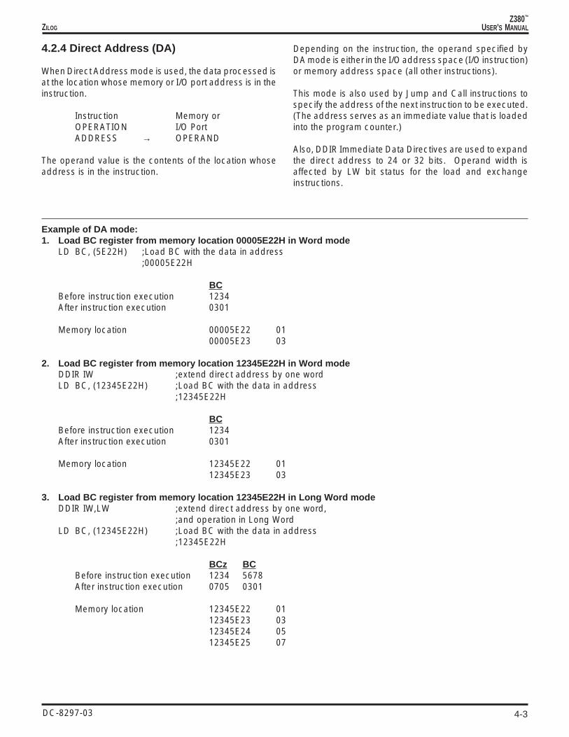
Example of DA mode:1. Load BC register from memory location 00005E22H in Word mode
LD BC, (5E22H) ;Load BC with the data in address;00005E22H
BCBefore instruction execution 1234After instruction execution 0301
Memory location 00005E22 0100005E23 03
2. Load BC register from memory location 12345E22H in Word modeDDIR IW ;extend direct address by one wordLD BC, (12345E22H) ;Load BC with the data in address
;12345E22H
BCBefore instruction execution 1234After instruction execution 0301
Memory location 12345E22 0112345E23 03
3. Load BC register from memory location 12345E22H in Long Word modeDDIR IW,LW ;extend direct address by one word,
;and operation in Long WordLD BC, (12345E22H) ;Load BC with the data in address
;12345E22H
BCz BCBefore instruction execution 1234 5678After instruction execution 0705 0301
Memory location 12345E22 0112345E23 0312345E24 0512345E25 07

4-4
Z380™
USER'S MANUAL
DC-8297-03
ZILOG
4.2.5 Indexed (X)
When the Indexed addressing mode is used, the dataprocessed is at the location whose address is the contentsof IX or IY in use, offset by an 8-bit signed displacement inthe instruction.
The Indexed address is computed by adding the 8-bittwo’s complement signed displacement specified in theinstruction to the contents of the IX or IY register in use, alsospecified by the instruction. Indexed addressing allowsrandom access to tables or other complex data structureswhere the address of the base of the table is known, but theparticular element index must be computed by the pro-gram.
The offset portion can be expanded to 16 or 24 bits,instead of eight bits by using DDIR Immediate Data Direc-tives (DDIR IB for 16-bit offset, DDIR IW for 24-bit offset).
Note that computation of the effective address is affectedby the operation mode (Native or Extended). In Nativemode, address computation is done in modulo 216, and inExtended mode, address computation is done in modulo232.
Address calculation: In Native mode, 0FFH encoding inthe instruction is sign extended to a 16-bit value before theaddress calculation, but calculation is done in modulo 216
and does not take into account the index register’sextended portion.
0000+ FFFF
FFFF
Instruction REGISTER MEMORYOPERATION REGISTER → ADDRESS →+ OPERANDDISPLACEMENT _____________________________________ ↑
Example of X mode:1. Load accumulator from location (IX-1) in Native mode
LD A, (IX-1) ;Load into the accumulator the;contents of the memory location;whose address is one less than;the contents of IX;Assume it is in Native mode
A IXz IXBefore instruction execution 01 0001 0000After instruction execution 23 0001 0000
Memory location 0001FFFF 23
4-5
Z380™
USER'S MANUALZILOG
DC-8297-03
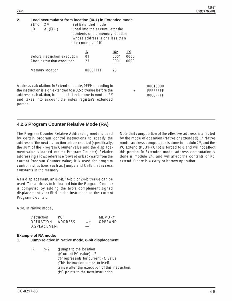
2. Load accumulator from location (IX-1) in Extended modeSETC XM ;Set Extended modeLD A, (IX-1) ;Load into the accumulator the
;contents of the memory location;whose address is one less than;the contents of IX
A IXz IXBefore instruction execution 01 0001 0000After instruction execution 23 0001 0000
Memory location 0000FFFF 23
Address calculation: In Extended mode, 0FFH encoding inthe instruction is sign extended to a 32-bit value before theaddress calculation, but calculation is done in modulo 232
and takes into account the index register’s extendedportion.
00010000+ FFFFFFFF
0000FFFF
4.2.6 Program Counter Relative Mode (RA)
The Program Counter Relative Addressing mode is usedby certain program control instructions to specify theaddress of the next instruction to be executed (specifically,the sum of the Program Counter value and the displace-ment value is loaded into the Program Counter). Relativeaddressing allows reference forward or backward from thecurrent Program Counter value; it is used for programcontrol instructions such as Jumps and Calls that accessconstants in the memory.
As a displacement, an 8-bit, 16-bit, or 24-bit value can beused. The address to be loaded into the Program Counteris computed by adding the two’s complement signeddisplacement specified in the instruction to the currentProgram Counter.
Note that computation of the effective address is affectedby the mode of operation (Native or Extended). In Nativemode, address computation is done in modulo 216, and thePC Extend (PC31-PC16) is forced to 0 and will not affectthis portion. In Extended mode, address computation isdone is modulo 232, and will affect the contents of PCextend if there is a carry or borrow operation.
Also, in Native mode,
Instruction PC MEMORYOPERATION ADDRESS →+ OPERANDDISPLACEMENT —↑
Example of RA mode:1. Jump relative in Native mode, 8-bit displacement
JR $-2 ;Jumps to the location;(Current PC value) – 2;’$’ represents for current PC value;This instruction jumps to itself.;since after the execution of this instruction,;PC points to the next instruction.

4-6
Z380™
USER'S MANUAL
DC-8297-03
ZILOG
4.2.6 Program Counter Relative Mode (RA) (Continued)
PCz PCBefore instruction execution 0000 1000After instruction execution 0000 0FFE
Address calculation: In Native mode, –2 is encoded as0FEH in the instruction, and it is sign extended to a 16-bitvalue before added to the Program Counter. Calculation isdone in modulo 216 and does not affect the Extendedportion of the Program Counter.
1000+ FFFE
FFFE
Address calculation: Since this is a 4-byte instruction, thePC value after fetch but before jump taking place is:
19590807+ 00000004
1959080B
The displacement portion, –5000H, is sign extended to a32-bit value before being added to the Program Counter.Calculation is done in modulo 232 and affects the Extendedportion of the Program Counter.
1959080B+ FFFFB000
1958B80B
2. Jump relative in Extended mode, 16-bit displacement
SETC XM ;Put it in Extended mode of operationJR $-5000H ;Jumps to the location
;(Current PC value) – 5000H;$ stands for current PC value;This instruction jumps to itself.
PCz PCBefore instruction execution 1959 0807After instruction execution 1958 B80B

4-7
Z380™
USER'S MANUALZILOG
DC-8297-03
4.2.7 Stack Pointer Relative Mode (SR)
For Stack Pointer Relative addressing mode, the dataprocessed is at the location whose address is the contentsof the Stack Pointer, offset by an 8-bit displacement in theinstruction.
The Stack Pointer Relative address is computed by addingthe 8-bit two’s complement signed displacement speci-fied in the instruction to the contents of the SP, alsospecified by the instruction. Stack Pointer Relative ad-dressing mode is used to specify data items to be found inthe stack, such as parameters passed to procedures.
Offset portion can be expanded to 16 or 24 bits by usingDDIR immediate instructions (DDIR IB for a 16-bit offset,DDIR IW for a 24-bit offset).
Note that computation of the effective address is affectedby the operation mode (Native or Extended). In Nativemode, address computation is done in modulo 216, mean-ing computation is done in 16-bit and does not affect upperhalf of the SP portion for calculation (wrap around within the16-bit). In Extended mode, address computation is donein modulo 232.
Also, the size of the data transfer is affected by the LWmode bit. In Word mode, transfer is done in 16 bits, and inLong Word mode, transfer is done in 32 bits.
Instruction SPOPERATION ADDRESS ——| MEMORYDISPLACEMENT ——+ OPERAND
Example of SR mode:1. Load HL from location (SP – 4) in Native mode, Word mode
LD HL, (SP–4) ;Load into the HL from the;contents of the memory location;whose address is four less than;the contents of SP.;Assume it is in Native/Word mode.
HLz HL SPz SPBefore instruction execution 1234 5678 07FF 7F00After instruction execution EFCD AB89 07FF 7F00
Memory location 07FF7EFC 8907FF7EFD AB
Address calculation: In Native mode, FCH (–4 in Decimal)encoding in the instruction is sign extended to a 16-bitvalue before the address calculation. Calculation is donein modulo 216 and does not take into account the StackPointer’s extended portion.
7F00+ FFFC
7EFC

4-8
Z380™
USER'S MANUAL
DC-8297-03
ZILOG
4.2.7 Stack Pointer Relative Mode (SR) (Continued)
2. Load HL from location (SP – 4) in Extended mode, Long Word modeSETC XM ;In Extended modeDDIR LW ;operate next instruction in Long Word modeLD HL, (SP–4) ;Load into the HL from the
;contents of the memory location;whose address is four less than;the contents of SP.
HLz HL SPz SPBefore instruction execution 1234 5678 07FF 7F00After instruction execution EFCD AB89 07FF 7F00
Memory location 07FF7EFC 8907FF7EFD AB07FF7EFE CD07FF7EFF EF
Address calculation: In Extended mode, FCH (–4 in Deci-mal) encoding in the instruction is sign extended to a 32-bit value before the address calculation, and calculation isdone in modulo 232.
07FF7F00+ FFFFFFFC
07FF7EFC
3. Load HL from location (SP + 10000H) in Extended mode, Long Word modeSETC XM ;In Extended mode,DDIR IW,LW ;operate next instruction in Long Word mode
;with a word immediate data.LD HL, (SP+10000) ;Load into the HL from the
;contents of the memory location;whose address is 10000H more than;the contents of SP.
HLz HL SPz SPBefore instruction execution 1234 5678 07FF 7F00After instruction execution EFCD AB89 07FF 7F00
Memory location 08007F00 8908007F01 AB08007F02 CD08007F03 EF
Address calculation: In Extended mode, 010000H encod-ing in the instruction is sign extended to a 32-bit valuebefore the address calculation, and calculation is done inmodulo 232.
07FF7F00+ 00010000
08007F00

4-9
Z380™
USER'S MANUALZILOG
DC-8297-03
4.3 DATA TYPES
The Z380 CPU can operate on bits, binary-coded decimal(BCD) digits (four bits), bytes (eight bits), words (16 bits or32 bits), byte strings, and word strings. Bits in registers canbe set, cleared, and tested.
The basic data type is a byte, which is also the basicaccessible element in the register, memory, and I/O addressspace. The 8-bit load, arithmetic, logical, shift, and rotateinstructions operate on bytes in registers or memory. Bytescan be treated as logical, signed numeric, or unsignednumeric value.
Words are operated on in a similar manner by the wordload, arithmetic, logical, and shift and rotate instructions.
Operation on 2-byte words is also supported. Sixteen-bitload and arithmetic instructions operate on words inregisters or memory; words can be treated as signed orunsigned numeric values. I/O reads and writes can be8-bit or 16-bit operations. Also, the Z380 CPU architecturesupports operation in Long Word mode to handle a 32-bitaddress manipulation. For that purpose, 16-bit wideregisters originally on the Z80 have been expanded to 32bits wide, along with the support of the arithmetic instructionneeded for a 32-bit address manipulation.
Bits are fully supported and addressed by number withina byte (see Figure 2-2). Bits within byte registers ormemory locations can be tested, set, or cleared.
Operation on binary-coded decimal (BCD) digits are sup-ported by Decimal Adjust Accumulator (DAA) and RotateDigit (RLD and RRD) instructions. BCD digits are stored inbyte registers or memory locations, two per byte. The DAAinstruction is used after a binary addition or subtraction ofBCD numbers. Rotate Digit instructions are used to shiftBCD digit strings in memory.
Strings of up to 65536 (64K) bytes of Byte data or Worddata can be manipulated by the Z380 CPU’s block move,block search, and block I/O instructions. The block moveinstructions allow strings of bytes/words in memory to bemoved from one location to another. Block search instruc-tions provide for scanning strings of bytes/words in memoryto locate a particular value. Block I/O instructions allowstrings of bytes or words to be transferred between memoryand a peripheral device.
Arrays are supported by Indexed mode (with 8-bit, 16-bit,or 24-bit displacement). Stack is supported by the Indexedand the Stack Pointer Relative addressing modes, and byspecial instructions such as Call, Return, Push, and Pop.
Zilog’s products are not authorized for use as critical compo-nents in life support devices or systems unless a specific writtenagreement pertaining to such intended use is executed betweenthe customer and Zilog prior to use. Life support devices orsystems are those which are intended for surgical implantationinto the body, or which sustains life whose failure to perform,when properly used in accordance with instructions for useprovided in the labeling, can be reasonably expected to result insignificant injury to the user.
Zilog, Inc. 210 East Hacienda Ave.Campbell, CA 95008-6600Telephone (408) 370-8000Telex 910-338-7621FAX 408 370-8056Internet: http://www.zilog.com
© 1994, 1995, 1996, 1997 by Zilog, Inc. All rights reserved. Nopart of this document may be copied or reproduced in any formor by any means without the prior written consent of Zilog, Inc.The information in this document is subject to change withoutnotice. Devices sold by Zilog, Inc. are covered by warranty andpatent indemnification provisions appearing in Zilog, Inc. Termsand Conditions of Sale only.
ZILOG, INC. MAKES NO WARRANTY, EXPRESS, STATUTORY,IMPLIED OR BY DESCRIPTION, REGARDING THE INFORMA-TION SET FORTH HEREIN OR REGARDING THE FREEDOM OFTHE DESCRIBED DEVICES FROM INTELLECTUAL PROPERTYINFRINGEMENT. ZILOG, INC. MAKES NO WARRANTY OF MER-CHANTABILITY OR FITNESS FOR ANY PURPOSE.
Zilog, Inc. shall not be responsible for any errors that may appearin this document. Zilog, Inc. makes no commitment to update orkeep current the information contained in this document.

5-1
Z380™
USER'S MANUALZILOG
DC-8297-03
5.1 INTRODUCTION
USER’s MANUAL
CHAPTER 5INSTRUCTION SET
The Z380™ CPU instruction set is a superset of the Z80 CPUand the Z180 MPU; the Z380 CPU is opcode compatiblewith the Z80 CPU/Z180 MPU. Thus, a Z80/Z180 programcan be executed on a Z380 CPU without modification. Theinstruction set is divided into 12 groups by function:
■ 8-Bit Load/Exchange Group
■ 16/32-Bit Load, Exchange, SWAP and Push/Pop Group
■ Block Transfers, and Search Group
■ 8-Bit Arithmetic and Logic Operations
■ 16/32-Bit Arithmetic Operations
■ 8-Bit Bit Manipulation, Rotate and Shift Group
■ 16-Bit Rotates and Shifts
5.2 PROCESSOR FLAGS
The Flag register contains six bits of status information thatare set or cleared by CPU operations (Figure 5-1). Four ofthese bits are testable (C, P/V, Z, and S) for use withconditional jump, call, or return instructions. Two flags arenot testable (H and N) and are used for binary-codeddecimal (BCD) arithmetic.
The Flag register provides a link between sequentiallyexecuted instructions, in that the result of executing oneinstruction may alter the flags, and the resulting value of theflags can be used to determine the operation of a subse-quent instruction. The program control instructions, whoseoperation depends on the state of the flags, are the Jump,Jump Relative, subroutine Call, Call Relative, and subrou-tine Return instructions; these instructions are referred toas conditional instructions.
Figure 5-1. Flag Register
■ Program Control Group
■ Input and Output Operations for External I/O Space
■ Input and Output Operations for Internal I/O Space
■ CPU Control Group
■ Decoder Directives
This chapter describes the instruction set of the Z380 CPU.Flags and condition codes are discussed in relation to theinstruction set. Then, the interpretability of instructions andtrap are discussed. The last part of this chapter is adetailed description of each instruction, listed in alphabeti-cal order by mnemonic. This section is intended as areference for Z380 CPU programmers. The entry for eachinstruction contains a complete description of the instruc-tion, including addressing modes, assembly languagemnemonics, and instruction opcode formats.
S Z X H X P/V N C
7 6 5 4 3 2 1 0
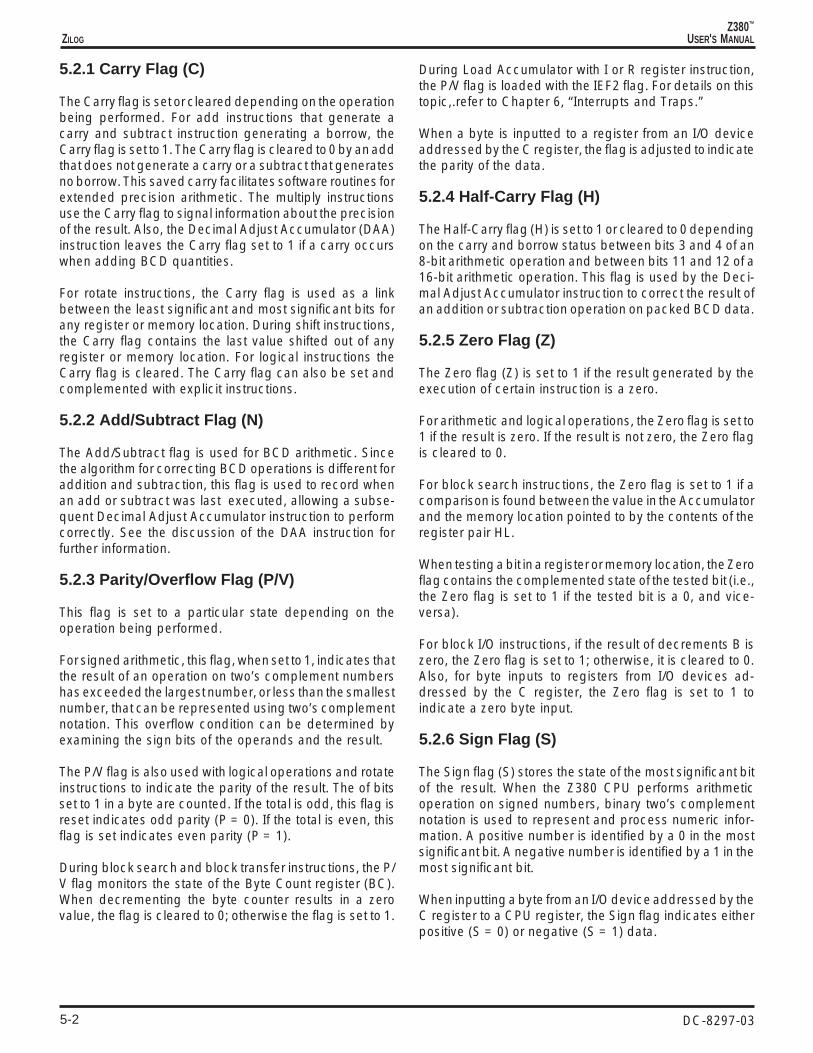
5-2
Z380™
USER'S MANUAL
DC-8297-03
ZILOG
5.2.1 Carry Flag (C)
The Carry flag is set or cleared depending on the operationbeing performed. For add instructions that generate acarry and subtract instruction generating a borrow, theCarry flag is set to 1. The Carry flag is cleared to 0 by an addthat does not generate a carry or a subtract that generatesno borrow. This saved carry facilitates software routines forextended precision arithmetic. The multiply instructionsuse the Carry flag to signal information about the precisionof the result. Also, the Decimal Adjust Accumulator (DAA)instruction leaves the Carry flag set to 1 if a carry occurswhen adding BCD quantities.
For rotate instructions, the Carry flag is used as a linkbetween the least significant and most significant bits forany register or memory location. During shift instructions,the Carry flag contains the last value shifted out of anyregister or memory location. For logical instructions theCarry flag is cleared. The Carry flag can also be set andcomplemented with explicit instructions.
5.2.2 Add/Subtract Flag (N)
The Add/Subtract flag is used for BCD arithmetic. Sincethe algorithm for correcting BCD operations is different foraddition and subtraction, this flag is used to record whenan add or subtract was last executed, allowing a subse-quent Decimal Adjust Accumulator instruction to performcorrectly. See the discussion of the DAA instruction forfurther information.
5.2.3 Parity/Overflow Flag (P/V)
This flag is set to a particular state depending on theoperation being performed.
For signed arithmetic, this flag, when set to 1, indicates thatthe result of an operation on two’s complement numbershas exceeded the largest number, or less than the smallestnumber, that can be represented using two’s complementnotation. This overflow condition can be determined byexamining the sign bits of the operands and the result.
The P/V flag is also used with logical operations and rotateinstructions to indicate the parity of the result. The of bitsset to 1 in a byte are counted. If the total is odd, this flag isreset indicates odd parity (P = 0). If the total is even, thisflag is set indicates even parity (P = 1).
During block search and block transfer instructions, the P/V flag monitors the state of the Byte Count register (BC).When decrementing the byte counter results in a zerovalue, the flag is cleared to 0; otherwise the flag is set to 1.
During Load Accumulator with I or R register instruction,the P/V flag is loaded with the IEF2 flag. For details on thistopic,.refer to Chapter 6, “Interrupts and Traps.”
When a byte is inputted to a register from an I/O deviceaddressed by the C register, the flag is adjusted to indicatethe parity of the data.
5.2.4 Half-Carry Flag (H)
The Half-Carry flag (H) is set to 1 or cleared to 0 dependingon the carry and borrow status between bits 3 and 4 of an8-bit arithmetic operation and between bits 11 and 12 of a16-bit arithmetic operation. This flag is used by the Deci-mal Adjust Accumulator instruction to correct the result ofan addition or subtraction operation on packed BCD data.
5.2.5 Zero Flag (Z)
The Zero flag (Z) is set to 1 if the result generated by theexecution of certain instruction is a zero.
For arithmetic and logical operations, the Zero flag is set to1 if the result is zero. If the result is not zero, the Zero flagis cleared to 0.
For block search instructions, the Zero flag is set to 1 if acomparison is found between the value in the Accumulatorand the memory location pointed to by the contents of theregister pair HL.
When testing a bit in a register or memory location, the Zeroflag contains the complemented state of the tested bit (i.e.,the Zero flag is set to 1 if the tested bit is a 0, and vice-versa).
For block I/O instructions, if the result of decrements B iszero, the Zero flag is set to 1; otherwise, it is cleared to 0.Also, for byte inputs to registers from I/O devices ad-dressed by the C register, the Zero flag is set to 1 toindicate a zero byte input.
5.2.6 Sign Flag (S)
The Sign flag (S) stores the state of the most significant bitof the result. When the Z380 CPU performs arithmeticoperation on signed numbers, binary two’s complementnotation is used to represent and process numeric infor-mation. A positive number is identified by a 0 in the mostsignificant bit. A negative number is identified by a 1 in themost significant bit.
When inputting a byte from an I/O device addressed by theC register to a CPU register, the Sign flag indicates eitherpositive (S = 0) or negative (S = 1) data.

5-3
Z380™
USER'S MANUALZILOG
DC-8297-03
5.2.7 Condition Codes
The Carry, Zero, Sign, and Parity/Overflow flags are usedto control the operation of the conditional instructions. Theoperation of these instructions is a function of the state ofone of the flags. Special mnemonics called conditioncodes are used to specify the flag setting to be testedduring execution of a conditional instruction; the conditioncodes are encoded into a 3-bit field in the instructionopcode itself.
Table 5-1 lists the condition code mnemonic, the flagsetting it represents, and the binary encoding for eachcondition code.
Table 5-1. Condition codes
Condition Codes for Jump, Call, and Return InstructionsMnemonic Meaning Flag Setting Binary Code
NZ Not Zero* Z = 0 000Z Zero* Z = 1 001NC No Carry* C = 0 010C Carry* C = 1 011NV No Overflow V = 0 100PO Parity Odd V = 0 100V Overflow V = 1 101PE Parity Even V = 1 101NS No Sign S = 0 110P Plus S = 0 110S Sign S = 1 111M Minus S = 1 111
*Abbreviated set
Condition Codes for Jump Relative and Call Relative InstructionsMnemonic Meaning Flag Setting Binary Code
NZ Not Zero Z = 0 100Z Zero Z = 1 101NC No Carry C = 0 110C Carry C = 1 111

5-4
Z380™
USER'S MANUAL
DC-8297-03
ZILOG
5.3 SELECT REGISTER
The Select Register (SR) controls the register set selectionand the operating modes of the Z380 CPU. The reservedbits in the SR are for future expansion; they will always readas zeros and should be written with zeros for future
compatibility. Access to this register is done by using thenewly added LDCTL instruction. Also, some of the instruc-tions like EXX, IM p, and DI/EI change the bit(s). The SRwas shown in Figure 5-2.
Reserved (0)
23 2122 17
IYBANK IYP Reserved (0) IXBANK IXP
20 1819 1631 2930 2528 2627 24
XSRYSR
Reserved (0)
7 56 1
MAINBANK ALT XM IM AFP
4 23 015 1314 912 1011 8
DSR
LW IEF1 0 LCK
Figure 5-2. Select Register
5.3.1. IY Bank Select (IYBANK)
This 2-bit field selects the register set to be used for the IYand IY’ registers. This field can be set independently of theregister set selection for the other Z380 CPU registers.Reset selects Bank 0 for IY and IY’.
5.3.2. IY or IY’ Register Select (IY’)
This bit controls and reports whether IY or IY’ is thecurrently active register. IY is selected when this bit iscleared, and IY’ is selected when this bit is set. Resetclears this bit, selecting IY.
5.3.3. IX Bank Select (IXBANK)
This 2-bit field selects the register set to be used for the IXand IX’ registers. This field can be set independently of theregister set selection for the other Z380 CPU registers.Reset selects Bank 0 for IX and IX’.
5.3.4. IX or IX’ Register Select (IX’)
This bit controls and reports whether IX or IX’ is thecurrently active register. IX is selected when this bit iscleared, and IX’ is selected when this bit is set. Resetclears this bit, selecting IX.
5.3.5. Main Bank Select (MAINBANK)
This 2-bit field selects the register set to be used for the A,F, BC, DE, HL, A’, F’, BC’, DE’, and HL’ registers. This fieldcan be set independently of the register set selection forthe other Z380 CPU registers. Reset selects Bank 0 forthese registers.
5.3.6. BC/DE/HL or BC’/DE’/HL’ RegisterSelect (ALT)
This bit controls and reports whether BC/DE/HL or BC’/DE’/HL’ is the currently active bank of registers. BC/DE/HL isselected when this bit is cleared, and BC’/DE’/HL’ isselected when this bit is set. Reset clears this bit, selectingBC/DE/HL.
5.3.7. Extended Mode (XM)
This bit controls the Extended/Native mode selection forthe Z380 CPU. This bit is set by the SETC XM instruction.This bit can not be reset by software, only by Reset. Whenthis bit is set, the Z380 CPU is in Extended mode. Resetclears this bit, and the Z380 CPU is in Native mode.

5-5
Z380™
USER'S MANUALZILOG
DC-8297-03
5.3.8. Long Word Mode (LW)
This bit controls the Long Word/Word mode selection forthe Z380 CPU. This bit is set by the SETC LW instructionand cleared by the RESC LW instruction. When this bit isset, the Z380 CPU is in Long Word mode; when this bit iscleared the Z380 CPU is in Word mode. Reset clears thisbit. Note that individual Word load and exchange instruc-tions may be executed in either Word or Long Word modeusing the DDIR W and DDIR LW decoder directives.
5.3.9. Interrupt Enable Flag (IEF)
This bit is the master Interrupt Enable for the Z380 CPU.This bit is set by the EI instruction and cleared by the DIinstruction, or on acknowledgment of an interrupt request.When this bit is set, interrupts are enabled; when this bit iscleared, interrupts are disabled. Reset clears this bit.
5.3.10. Interrupt Mode (IM)
This 2-bit field controls the interrupt mode for the /INT0interrupt request. These bits are controlled by the IMinstructions (00 = IM 0, 01 = IM 1, 10 = IM 2, 11 = IM 3).Reset clears both of these bits, selecting Interrupt Mode 0.
5.3.11. Lock (LCK)
This bit controls the Lock/Unlock status of the Z380 CPU.This bit is set by the SETC LCK instruction and cleared bythe RESC LCK instruction. When this bit is set, no busrequests will be accepted, providing exclusive access tothe bus by the Z380 CPU. When this bit is cleared, the Z380CPU will grant bus requests in the normal fashion. Resetclears this bit.
5.3.12. AF or AF’ Register Select (AF’)
This bit controls and reports whether AF or AF’ is thecurrently active pair of registers. AF is selected when thisbit is cleared, and AF’ is selected when this bit is set. Resetclears this bit, selecting AF.
5.4 INSTRUCTION EXECUTION AND EXCEPTIONS
Three types of exception conditions—interrupts, trap, andReset—can alter the normal flow of program execution.Interrupts are asynchronous events generated by a deviceexternal to the CPU; peripheral devices use interrupts torequest service from the CPU. Trap is a synchronous eventgenerated internally in the CPU by executing undefinedinstructions. Reset is an asynchronous event generated byoutside circuits. It terminates all current activities and putsthe CPU into a known state. Interrupts and Traps arediscussed in detail in Chapter 6, and Reset is discussed indetail in Chapter 7. This section examines the relationshipbetween instructions and the exception conditions.
5.4.1 Instruction Execution and Interrupts
When the CPU receives an interrupt request, and it isenabled for interrupts of that class, the interrupt is normallyprocessed at the end of the current instruction. However,the block transfer and search instructions are designed tobe interruptible so as to minimize the length of time it takesthe CPU to respond to an interrupt. If an interrupt requestis received during a block move, block search, or blockI/O instruction, the instruction is suspended after thecurrent iteration. The address of the instruction itself, ratherthan the address of the following instruction, is saved onthe stack, so that the same instruction is executed againwhen the interrupt handler executes an interrupt return
instruction. The contents of the repetition counter and theregisters that index into the block operands are such that,after each iteration, when the instruction is reissued uponreturning from an interrupt, the effect is the same as if theinstruction were not interrupted. This assumes, of course,that the interrupt handler preserves the registers.
5.4.2 Instruction Execution and Trap
The Z380 MPU generates a Trap when an undefinedopcode is encountered. The action of the CPU in responseto Trap is to jump to address 00000000H with the statusbit(s) set. This response is similar to the Z180 MPU’s actionon execution of an undefined instruction. The Trap isenabled immediately after reset, and it is not maskable.This feature can be used to increase software reliability orto implement “extended” instructions. An undefined op-code can be fetched from the instruction stream, or it canbe returned as a vector in an interrupt acknowledgetransaction in Interrupt mode 0.
Since it jumps to address 00000000H, it is necessary tohave a Trap handling routine at the beginning of theprogram if processing is to proceed. Otherwise, it behavesjust like a reset for the CPU. For a detailed description, referto Chapter 6.

5-6
Z380™
USER'S MANUAL
DC-8297-03
ZILOG
5.5 INSTRUCTION SET FUNCTIONAL GROUPS
An Exchange instruction is available for swapping thecontents of the accumulator with another register or withmemory, as well as between registers. Also, exchangeinstructions are available which swap the contents of theregister in the primary register bank and auxiliary registerbank.
The instruction in this group does not affect the flags.
This section presents an overview of the Z380 instructionset, arranged by functional groups. (See Section 5.5 for anexplanation of the notation used in Tables 5-2 through 5-11).
5.5.1 8-Bit Load/Exchange Group
This group of instructions (Table 5-2) includes load instruc-tions for transferring data between byte registers, transfer-ring data between a byte register and memory, and load-ing immediate data into byte register or memory. For thesupported source/destination combinations, refer to Table5-3.
Table 5-3. 8-Bit Load Group Allowed Source/Destination CombinationsSource
Dist. A B C D E H L IXH IXL IYH IYL n (nn) (BC) (DE) (HL) (IX+d) (IY+d)
A √ √ √ √ √ √ √ √ √ √ √ √ √ √ √ √ √ √B √ √ √ √ √ √ √ √ √ √ √ √ √ √ √C √ √ √ √ √ √ √ √ √ √ √ √ √ √ √D √ √ √ √ √ √ √ √ √ √ √ √ √ √ √
E √ √ √ √ √ √ √ √ √ √ √ √ √ √ √H √ √ √ √ √ √ √ √ √ √ √L √ √ √ √ √ √ √ √ √ √ √IXH √ √ √ √ √ √ √ √
IXL √ √ √ √ √ √ √ √IYH √ √ √ √ √ √ √ √IYL √ √ √ √ √ √ √ √(BC) √
(DE) √(HL) √ √ √ √ √ √ √ √(nn) √(IX+d) √ √ √ √ √ √ √ √(IY+d) √ √ √ √ √ √ √ √
Table 5-2. 8-Bit Load Group Instructions
Instruction Name Format Note
Exchange with Accumulator EX A,rEX A,(HL)
Exchange r and r’ EX r,r’ r=A, B, C, D, E, H or LLoad Accumulator LD A,src See Table 5-3
LD dst,A See Table 5-3Load Immediate LD dst,n See Table 5-3
LD (HL),n See Table 5-3Load Register (Byte) LD R,src See Table 5-3
LD R,(HL) See Table 5-3LD dst,R See Table 5-3LD (HL),R See Table 5-3
Note: √ are supported combinations.

5-7
Z380™
USER'S MANUALZILOG
DC-8297-03
5.5.2 16-Bit and 32-Bit Load, Exchange,SWAP, and PUSH/POP Group
This group of load, exchange, and PUSH/POP instructions(Table 5-4) allows one or two words of data (two bytesequal one word) to be transferred between registers andmemory.
The exchange instructions (Table 5-5) allow for switchingbetween the primary and alternate register files, exchang-ing the contents of two register files, exchanging thecontents of an addressing register with the top word on thestack. For possible combinations of the word exchangeinstructions, refer to Table 5-5. The 16-bit and 32-bit loadsinclude transfer between registers and memory and imme-diate loads of registers or memory. The Push and Popstack instructions are also included in this group. None ofthese instructions affect the CPU flags, except for EX AF,AF’.
Table 5-6 has the supported source/destination combina-tion for the 16-bit and 32-bit load instructions. The transfersize, 16-bit or 32-bit, is determined by the status of LW bitin SR, or by DDIR Decoder Directives.
PUSH/POP instructions are used to save/restore the con-tents of a register onto the stack. It can be used toexchange data between procedures, save the currentregister file on context switching, or manipulate data on thestack, such as return addresses. Supported sources arelisted in Table 5-7.
Swap instructions allows swapping of the contents of theWord wide register (BC, DE, HL, IX, or IY) with its Extendedportion. These instructions are useful to manipulate theupper word of the register to be set in Word mode. Forexample, when doing data accesses, other than00000000H-0000FFFFH address range, use this instruc-tion to set “data frame” addresses.
This group of instructions is affected by the status of the LWbit in SR (Select Register), and Decoder Directives whichspecifies the operation mode in Word or Long Word.
Table 5-4. 16-Bit and 32-Bit Load, Exchange, PUSH/POP Group Instructions
Instruction Name Format Note
Exchange Word/Long Word Registers EX dst,src See Table 5-5Exchange Byte/Word Registers with Alternate Bank EXXExchange Register Pair with Alternate Bank EX RR,RR’ RR = AF, BC, DE, or HL
Exchange Index Register with Alternate Bank EXXXEXXY
Exchange All Registers with Alternate Bank EXALLLoad Word/Long Word Registers LD dst,src See Table 5-6
LDW dst,src See Table 5-6POP POP dst See Table 5-7PUSH PUSH src See Table 5-7Swap Contents of D31-D16 and D15-D0 SWAP dst dst = BC, DE, HL, IX, or IY
Table 5-5. Supported Source and DestinationCombination for 16-Bit and 32-Bit
Exchange Instructions
SourceDestination BC DE HL IX IY
BC √ √ √ √DE √ √ √HL √ √IX √(SP) √ √ √
Note: √ are supported combinations. The exchange in-structions which designate IY register as destination arecovered by the other combinations. These ExchangeWord instructions are affected by Long Word mode.

5-8
Z380™
USER'S MANUAL
DC-8297-03
ZILOG
5.5.2 16-Bit and 32-Bit Load, Exchange,SWAP and PUSH/POP Group (Continued)
Table 5-6. Supported Source and Destination Combination for 16-Bit and 32-Bit Load Instructions.
SourceDestination BC DE HL IX IY SP nn (nn) (BC) (DE) (HL) (IX+d) (IY+d) (SP+d)
BC L L L L L IL IL L L L IL IL ILDE L L L L L IL IL L L L IL IL ILHL L L L L L IL IL L L L IL IL ILIX L L L L IL IL L L L IL ILIY L L L L IL IL L L L IL ILSP L L L IL IL(BC) L L L L L ILW(DE) L L L L L ILW(HL) L L L L L ILW(nn) IL IL IL IL IL IL(IX+d) IL IL IL IL(IY+d) IL IL IL IL(SP+d) IL IL IL IL IL
Note: The column with the character(s) are the allowedsource/destination combinations. The combination with“L” means that the instruction is affected by Long Word
mode, “I” means that the instruction is can be used withDDIR Immediate instruction. Also, “W” means the instruc-tion uses the mnemonic of “LDW” instead of “LD”.
Table 5-7. Supported Operand for PUSH/POP Instructions
AF BC DE HL IX IY SR nn
PUSH √ √ √ √ √ √ √ √POP √ √ √ √ √ √ √
Note: These PUSH/POP instructions are affected by Long Word mode of operations.
Various Z380 CPU registers are dedicated to specificfunctions for these instructions—the BC register for acounter, the DEz/DE and HLz/HL registers for memorypointers, and the accumulator for holding the byte valuebeing sought. The repetitive forms of these instructions areinterruptible; this is essential since the repetition count canbe as high as 65536. The instruction can be interruptedafter any interaction, in which case the address of theinstruction itself, rather than next one, is saved on thestack. The contents of the operand pointer registers, aswell as the repetition counter, are such that the instructioncan simply be reissued after returning from the interruptwithout any visible difference in the instruction execution.
In case of Word or Long Word block transfer instructions,the counter value held in the BC register is decrementedby two or four, depending on the LW bit status. Sinceexiting from these instructions will be done when countervalue gets to 0, the count value stored in the BC registers
5.5.3 Block Transfer and Search Group
This group of instructions (Table 5-8) supports blocktransfer and string search functions. Using these instruc-tions, a block of up to 65536 bytes of byte, Word, or LongWord data can be moved in memory, or a byte string canbe searched until a given value is found. All the operationscan proceed through the data in either direction. Further-more, the operations can be repeated automatically whiledecrementing a length counter until it reaches zero, or theycan operate on one storage unit per execution with thelength counter decremented by one and the source anddestination pointer register properly adjusted. The latterform is useful for implementing more complex operationsin software by adding other instructions within a loopcontaining the block instructions.

5-9
Z380™
USER'S MANUALZILOG
DC-8297-03
has to be an even number (D0 = 0) in Word mode transfer,and a multiple of four in Long Word mode (D1 and D0 areboth 0). Also, in Word or Long Word Block transfer,memory pointer values are recommended to be evennumbers so the number of the transactions will be mini-mized.
Note that regardless of the Z380’s operation mode, Nativeor Extended, memory pointer increment/decrement will bedone in modulo 232. For example, if the operation is LDI andHL31-HL0 (HLz and HL) hold 0000FFFF, after the opera-tion the value in the HL31-HL0 will be 0010000.
Table 5-8. Block Transfer and Search Group
Instruction Name Format
Compare and Decrement CPDCompare, Decrement and Repeat CPDRCompare and Increment CPICompare, Increment and Repeat CPIRLoad and Decrement LDDLoad , Decrement and Repeat LDDILoad and Increment LDILoad, Increment and Repeat LDIRLoad and Decrement in Word/Long Word LDDWLoad, Decrement and Repeat in Word/Long Word
LDDRWLoad and Increment in Word/Long Word LDIWLoad, Increment and Repeat in Word/Long Word
LDIRW
5.5.4 8-bit Arithmetic and Logical Group
This group of instructions (Table 5-9) perform 8-bit arith-metic and logical operations. The Add, Add with Carry,Subtract, Subtract with Carry, AND, OR, Exclusive OR, andCompare takes one input operand from the accumulatorand the other from a register, from immediate data in theinstruction itself, or from memory. For memory addressingmodes, follows are supported—Indirect Register, Indexed,and Direct Address—except multiplies, which returns the16-bit result to the same register by multiplying the upperand lower bytes of one of the register pair (BC, DE, HL, orSP).
The Increment and Decrement instructions operate ondata in a register or in memory; all memory addressingmodes are supported. These instructions operate only onthe accumulator—Decimal Adjust, Complement, and Ne-gate. The final instruction in this group, Extend Sign, setsthe CPU flags according to the computed result.
The EXTS instruction extends the sign bit and leaves theresult in the HL register. If it is in Long Word mode, HLz(HL31-HL16) portion is also affected.
The TST instruction is a nondestructive AND instruction. ItANDs "A" register and source, and changes flags accord-ing to the result of operation. Both source and destinationvalues will be preserved.
Table 5-9. Supported Source/Destination for 8-Bit Arithmetic and Logic Group
src/Instruction Name Format dst A B C D E H L IXH IXL IYH IYL n (HL) (IX+d) (IY+x)
Add With Carry (Byte) ADC A,src src √ √ √ √ √ √ √ √ √ √ √ √ √ √ √Add (Byte) ADD A,src src √ √ √ √ √ √ √ √ √ √ √ √ √ √ √AND AND [A,]src src √ √ √ √ √ √ √ √ √ √ √ √ √ √ √Compare (Byte) CP [A,]src src √ √ √ √ √ √ √ √ √ √ √ √ √ √ √
Complement Accumulator CPL [A] dst √Decimal Adjust Accumulator DAA dst √Decrement (Byte) DEC dst dst √ √ √ √ √ √ √ √ √ √ √ √ √ √ √Extend Sign (Byte) EXTS [A] dst √
Increment (Byte) INC dst dst √ √ √ √ √ √ √ √ √ √ √ √ √ √ √Multiply (Byte) MLT src Note 1Negate Accumulator NEG [A] dst √OR OR [A,]src src √ √ √ √ √ √ √ √ √ √ √ √ √ √ √
Subtract with Carry (Byte) SBC A,src src √ √ √ √ √ √ √ √ √ √ √ √ √ √ √Subtract (Byte) SUB [A,]src src √ √ √ √ √ √ √ √ √ √ √ √ √ √ √Nondestructive Test TST dst src √ √ √ √ √ √ √ √ √Exclusive OR XOR [A,]src src √ √ √ √ √ √ √ √ √ √ √ √ √ √ √
Note 1: dst = BC, DE, HL, or SP.

5-10
Z380™
USER'S MANUAL
DC-8297-03
ZILOG
5.5.5 16-Bit Arithmetic Operation
This group of instructions (Table 5-10) provide 16-bitarithmetic instructions. The Add, Add with Carry, Subtract,Subtract with Carry, AND, OR, Exclusive OR, and Com-pare takes one input operand from an addressing registerand the other from a 16-bit register, or from the instructionitself; the result is returned to the addressing register. The16-bit Increment and Decrement instructions operate ondata found in a register or in memory; the Indirect Registeror Direct Address addressing mode can be used tospecify the memory operand.
The remaining 16-bit instructions provide general arith-metic capability using the HL register as one of the inputoperands. The word Add, Subtract, Compare, and signedand unsigned Multiply instructions take one input operandfrom the HL register and the other from a 16-bit register,from the instruction itself, or from memory using Indexed
Table 5-10. 16-Bit Arithmetic Operation
src/Instruction Name Format dst BC DE HL SP IX IY nn (nn) (IX+d) (IY+d)
Add With Carry (Word) ADC HL,src src √ √ √ √ADCW [HL],src src √ √ √ √ √ √ √ √
Add (Word) ADD HL,src src √ √ √ √ √ XADD IX,src src √ √ √ √ XADD IY,src src √ √ √ √ XADDW [HL,]src src √ √ √ √ √ √ √ √
Add to Stack Pointer ADD SP,nn src √ XAND Word ANDW [HL,]src src √ √ √ √ √ √ √ √Complement Accumulator CPLW [HL] dst √Compare (Word) CPW [HL,]src src √ √ √ √ √ √ √ √Decrement (Word) DEC[W] dst dst √ √ √ √ √ √ XDivide Unsigned DIVUW [HL,]src src √ √ √ √ √ √ √ √Extend Sign (Word) EXTSW [HL] dst √Increment (Word) INC[W] dst dst √ √ √ √ √ √ XMultiply Word Signed MULT [HL,]src src √ √ √ √ √ √ √ √Multiply Word Unsigned MULTUW [HL,]src src √ √ √ √ √ √ √ √Negate Accumulator NEGW [A] dst √OR Word ORW [HL,]src src √ √ √ √ √ √ √ √Subtract with Carry (Word) SBC HL,src src √ √ √ √ √
SBCW [HL],src src √ √ √ √ √ √ √ √Subtract (Word) SUB HL,(nn) src √ X
SUBW [HL,]src src √ √ √ √ √ √ √ √Subtract from Stack Pointer SUB SP,nn src √ XExclusive OR XORW [HL,]src src √ √ √ √ √ √ √ √
Note: that the instructions with “X” at the rightmost column is affected byExtended mode. These operate across all the 32 bits in Modulo 232 foraddress calculation.
or Direct Address addressing mode. The 32-bit result of amultiply is returned to the HLz and HL (HL31-HL0). Theunsigned divide instruction takes a 16-bit dividend fromthe HL register and a 16-bit divisor from a register, from theinstruction, or memory using the Indexed mode. The 16-bitquotient is returned in the HL register and the 16-bitreminder is returned to the HLz (HL31-HL16). The ExtendSign instruction takes the contents of the HL register anddelivers the 32-bit result to the HLz and HL registers. TheNegate HL instruction negates the contents of the HLregister.
Except for Increment, Decrement, and Extend Sign, all theinstructions in this group set the CPU flags to reflect thecomputed result.

5-11
Z380™
USER'S MANUALZILOG
DC-8297-03
5.5.6 8-Bit Manipulation, Rotate and ShiftGroup
Instructions in this group (Table 5-11) test, set, and resetbits within bytes, and rotate and shift byte data one bitposition. Bits to be manipulated are specified by a fieldwithin the instruction. Rotate can optionally concatenatethe Carry flag to the byte to be manipulated. Both left andright shifting is supported. Right shifts can either shift 0 intobit 7 (logical shifts), or can replicate the sign in bits 6 and7 (arithmetic shifts). All these instructions, Set Bit andReset Bit, set the CPU flags according to the calculatedresult; the operand can be a register or a memory location
specified by the Indirect Register or Indexed addressingmode.
The RLD and RRD instructions are provided for manipulat-ing strings of BCD digits; these rotate 4-bit quantities inmemory specified by the Indirect Register. The low-orderfour bits of the accumulator are used as a link betweenrotation of successive bytes.
Table 5-11. Bit Set/Reset/Test, Rotate and Shift Group
Instruction Name Format A B C D E H L (HL) (IX+d) (IY+d)
Bit Test BIT dst √ √ √ √ √ √ √ √ √ √Reset Bit RES dst √ √ √ √ √ √ √ √ √ √Rotate Left RL dst √ √ √ √ √ √ √ √ √ √Rotate Left Accumulator RLA √
Rotate Left Circular RLC dst √ √ √ √ √ √ √ √ √ √Rotate Left Circular (Accumulator) RLCA √Rotate Left Digit RLD √Rotate Right RR dst √ √ √ √ √ √ √ √ √ √
Rotate Right Accumulator RRA √Rotate Right Circular RRC dst √ √ √ √ √ √ √ √ √ √Rotate Right Circular (Accumulator) RRCA √Rotate Right Digit RRD √
Set Bit SET dst √ √ √ √ √ √ √ √ √ √Shift Left Arithmetic SLA dst √ √ √ √ √ √ √ √ √ √Shift Right Arithmetic SRA dst √ √ √ √ √ √ √ √ √ √Shift Right Logical SRL √ √ √ √ √ √ √ √ √ √
5.5.7 16-Bit Manipulation, Rotate and ShiftGroup
Instructions in this group (Table 5-12) rotate and shift worddata one bit position. Rotate can optionally concatenatethe Carry flag to the word to be manipulated. Both left andright shifting is supported. Right shifts can either shift 0 into
bit 15 (logical shifts), or can replicate the sign in bits 14 and15 (arithmetic shifts). The operand can be a register pair ormemory location specified by the Indirect Register orIndexed addressing mode, as shown below.
Table 5-12. 16-Bit Rotate and Shift Group.
DestinationInstruction Name Format BC DE HL IX IY (HL) (HL) (IX+d) (IY+d)
Rotate Left Word RLW dst √ √ √ √ √ √ √ √ √Rotate Left Circular Word RLCW dst √ √ √ √ √ √ √ √ √Rotate Right Word RRW dst √ √ √ √ √ √ √ √ √Rotate Right Circular Word RRCW dst √ √ √ √ √ √ √ √ √Shift Left Arithmetic Word SLAW dst √ √ √ √ √ √ √ √ √Shift Right Arithmetic Word SRAW dst √ √ √ √ √ √ √ √ √Shift Right Logical Word SRLW √ √ √ √ √ √ √ √ √

5-12
Z380™
USER'S MANUAL
DC-8297-03
ZILOG
5.5.8 Program Control Group
This group of instructions (Table 5-13) affect the ProgramCounter (PC) and thereby control program flow. The CPUregisters and memory are not altered except for the StackPointer and the Stack, which play a significant role inprocedures and interrupts. (An exception is Decrementand Jump if Non-Zero [DJNZ], which uses a register as aloop counter.) The flags are also preserved except for thetwo instructions specifically designed to set and comple-ment the Carry flag.
The Set/Reset Condition flag instructions can be used withConditional Jump, conditional Jump Relative, ConditionalCall, and Conditional Return instructions to control theprogram flow.
The Jump and Jump Relative (JR) instructions provide aconditional transfer of control to a new location if theprocessor flags satisfy the condition specified in the in-struction. Jump Relative, with an 8-bit offset (JR e), is a twobyte instruction that jumps any instructions within therange –126 to +129 bytes from the location of this instruc-tion. Most conditional jumps in programs are made tolocations only a few bytes away; the Jump Relative, with an8-bit offset, exploits this fact to improve code compact-ness and efficiency. Jump Relative, with a 16-bit offset (JR[cc,]ee), is a four byte instruction that jumps any instruc-tions within the range –32765 to +32770 bytes from thelocation of this instruction, and Jump Relative, with a 24-bitoffset (JR [cc,] eee), is a five byte instruction that jumps anyinstructions within the range –8388604 to +8388611 bytesfrom the location of this instruction. By using these JumpRelative instructions with 16-bit or 24-bit offsets allows towrite relocatable (or location independent) programs.
Call and Restart are used for calling subroutines; thecurrent contents of the PC are pushed onto the stack andthe effective address indicated by the instruction is loaded
Table 5-13. Program Control Group Instructions
Instruction Name Format nn (PC+d) (HL) (IX) (IY)
Call CALL cc,dst √Complement Carry Flag CCFCall Relative CALR cc,dst √Decrement and Jump if Non-zero DJNZ dst √
Jump JP cc,dst √JP dst √ √ √
Jump Relative JR cc,dst √Return RET ccRestart RST p √Set Carry Flag SCF
into the PC. The use of a procedure address stack in thismanner allows straightforward implementation of nestedand recursive procedures. Call, Jump, and Jump Relativecan be unconditional or based on the setting of a CPU flag.
Call Relative (CALR) instructions work just like ordinaryCall instructions, but with Relative address. An 8-bit, 16-bit, or 24-bit offset value can be used, and that allows to callprocedure within the range of –126 to +129 bytes (8-bitoffset;CALR [cc,]e), –32765 to +32770 bytes (16-bit offset;CALR [cc,]ee), or –8388604 to +8388611 bytes (JR [cc,]eee) are supported. These instructions are really useful toprogram relocatable programs.
Jump is available with Indirect Register mode in additionto Direct Address mode. It can be useful for implementingcomplex control structures such as dispatch tables. Whenusing Direct Address mode for a Jump or Call, the operandis used as an immediate value that is loaded into the PC tospecify the address of the next instruction to be executed.
The conditional Return instruction is a companion to thecall instruction; if the condition specified in the instructionis satisfied, it loads the PC from the stack and pops thestack.
A special instruction, Decrement and Jump if Non-Zero(DJNZ), implements the control part of the basic PascalFOR loop which can be implemented in an instruction. Itsupports 8-bit, 16-bit, and 24-bit displacement.
Note that Jump Relative, Call Relative, and DJNZ instruc-tions use modulo 216 in Native mode, and 232 in Extendedmode for address calculation. So it is possible that theZ380 CPU can jump to an unexpected address.

5-13
Z380™
USER'S MANUALZILOG
DC-8297-03
5.5.9 External Input/Output InstructionGroup
This group of instructions (Table 5-14) are used for trans-ferring a byte, a word, or string of bytes or words betweenperipheral devices and the CPU registers or memory. ByteI/O port addresses transfer bytes on D7-D0 only. These 8-bit peripherals in a 16-bit data bus environment must beconnected to data line D7-D0. In an 8-bit data bus environ-ment, word I/O instructions to external I/O peripheralsshould not be used; however, on-chip peripherals which isexternal to the CPU core and assigned as word I/O devicecan still be accessed by word I/O instructions.
The instructions for transferring a single byte (IN, OUT) cantransfer data between any 8-bit CPU register or memoryaddress specified in the instruction and the peripheral portspecified by the contents of the C register. The IN instruc-tion sets the CPU flags according to the input data;however, special instructions restricted to using the CPUaccumulator and Direct Address mode and do not affectthe CPU flags. Another variant tests an input port specifiedby the contents of the C register and sets the CPU flagswithout modifying CPU registers or memory.
The instructions for transferring a single word (INW, OUTW)can transfer data between the register pair and the periph-eral port specified by the contents of the C register. ForWord I/O, the contents of B, D, or H appear on D7-D0 and
the contents of C, E, or L appear D15-D7. These instruc-tions do not affect the CPU flags.
Also, there are I/O instructions available which allow tospecify 16-bit absolute I/O address (with DDIR decoderdirectives, a 24-bit or 32-bit address is specified) is avail-able. These instructions do not affect the CPU flags.
The remaining instructions in this group form a powerfuland complete complement of instructions for transferringblocks of data between I/O ports and memory. The opera-tion of these instructions is very similar to that of the blockmove instructions described earlier, with the exceptionthat one operand is always an I/O port whose addressremains unchanged while the address of the other oper-and (a memory location) is incremented or decremented.InWord mode of transfer, the counter (i.e., BC register) holdsthe number of transfers, rather than number of bytes totransfer in memory-to-memory word block transfer. Bothbyte and word forms of these instructions are available.The automatically repeating forms of these instructions areinterruptible, like memory-to-memory transfer.
The I/O addresses output on the address bus is de-pendant on the I/O instruction, as listed in Table 2-1.

5-14
Z380™
USER'S MANUAL
DC-8297-03
ZILOG
5.5.9 External Input/Output Instruction Group (Continued)
Table 5-14. External I/O Group Instructions.
Instruction Name Format
Input IN dst,(C) dst=A, B, C, D, E, H or LInput Accumulator IN A,(n)Input to Word-Wide Register INW dst,(C) dst=BC, DE or HLInput Byte from Absolute Address INAW A,(nn)
Input Word from Absolute Address INAW HL,(nn)Input and Decrement (Byte) INDInput and Decrement (Word) INDWInput, Decrement, and Repeat (Byte) INDR
Input, Decrement, and Repeat (Word) INDRWInput and Increment (Byte) INIInput and Increment (Word) INIWInput, Increment, and Repeat (Byte) INIR
Input, Increment, and Repeat (Word) INIRWOutput OUT (C),src src = A, B, C, D, E, H, L, or nOutput Accumulator OUT (n),AOutput from Word-Wide Register OUTW (C), src src = BC, DE, HL, or nn
Output Byte from Absolute Address OUTAW (nn),AOutput Word from Absolute Address OUTAW (nn),HLOutput and Decrement (Byte) OUTDOutput and Decrement (Word) OUTDW
Output, Decrement, and Repeat (Byte) OTDROutput, Decrement, and Repeat (Word) OTDRWOutput and Increment (Byte) OUTIOutput and Increment (Word) OTIWOutput, Increment, and Repeat (Byte) OTIROutput, Increment, and Repeat (Word) OTIRW
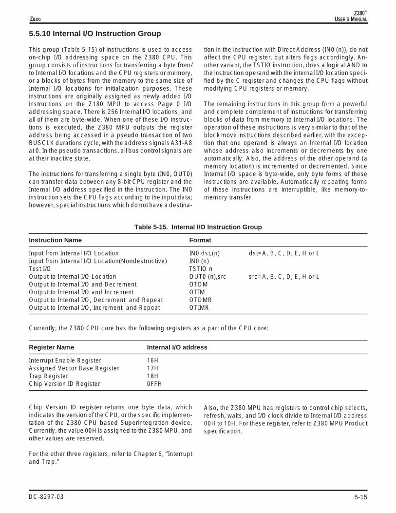
5-15
Z380™
USER'S MANUALZILOG
DC-8297-03
5.5.10 Internal I/O Instruction Group
This group (Table 5-15) of instructions is used to accesson-chip I/O addressing space on the Z380 CPU. Thisgroup consists of instructions for transferring a byte from/to Internal I/O locations and the CPU registers or memory,or a blocks of bytes from the memory to the same size ofInternal I/O locations for initialization purposes. Theseinstructions are originally assigned as newly added I/Oinstructions on the Z180 MPU to access Page 0 I/Oaddressing space. There is 256 Internal I/O locations, andall of them are byte-wide. When one of these I/O instruc-tions is executed, the Z380 MPU outputs the registeraddress being accessed in a pseudo transaction of twoBUSCLK durations cycle, with the address signals A31-A8at 0. In the pseudo transactions, all bus control signals areat their inactive state.
The instructions for transferring a single byte (IN0, OUT0)can transfer data between any 8-bit CPU register and theInternal I/O address specified in the instruction. The IN0instruction sets the CPU flags according to the input data;however, special instructions which do not have a destina-
tion in the instruction with Direct Address (IN0 (n)), do notaffect the CPU register, but alters flags accordingly. An-other variant, the TSTIO instruction, does a logical AND tothe instruction operand with the internal I/O location speci-fied by the C register and changes the CPU flags withoutmodifying CPU registers or memory.
The remaining instructions in this group form a powerfuland complete complement of instructions for transferringblocks of data from memory to Internal I/O locations. Theoperation of these instructions is very similar to that of theblock move instructions described earlier, with the excep-tion that one operand is always an Internal I/O locationwhose address also increments or decrements by oneautomatically, Also, the address of the other operand (amemory location) is incremented or decremented. SinceInternal I/O space is byte-wide, only byte forms of theseinstructions are available. Automatically repeating formsof these instructions are interruptible, like memory-to-memory transfer.
Table 5-15. Internal I/O Instruction Group
Instruction Name Format
Input from Internal I/O Location IN0 dst,(n) dst=A, B, C, D, E, H or LInput from Internal I/O Location(Nondestructive) IN0 (n)Test I/O TSTIO nOutput to Internal I/O Location OUT0 (n),src src=A, B, C, D, E, H or LOutput to Internal I/O and Decrement OTDMOutput to Internal I/O and Increment OTIMOutput to Internal I/O, Decrement and Repeat OTDMROutput to Internal I/O, Increment and Repeat OTIMR
Currently, the Z380 CPU core has the following registers as a part of the CPU core:
Register Name Internal I/O address
Interrupt Enable Register 16HAssigned Vector Base Register 17HTrap Register 18HChip Version ID Register 0FFH
Chip Version ID register returns one byte data, whichindicates the version of the CPU, or the specific implemen-tation of the Z380 CPU based Superintegration device.Currently, the value 00H is assigned to the Z380 MPU, andother values are reserved.
For the other three registers, refer to Chapter 6, “Interruptand Trap.”
Also, the Z380 MPU has registers to control chip selects,refresh, waits, and I/O clock divide to Internal I/O address00H to 10H. For these register, refer to Z380 MPU Productspecification.

5-16
Z380™
USER'S MANUAL
DC-8297-03
ZILOG
5.5.11 CPU Control Group
The instructions in this group (Table 5-16) act upon theCPU control and status registers or perform other functionsthat do not fit into any of the other instruction groups. Theseinclude two instructions used for returning from an inter-rupt service routine. Return from Nonmaskable Interrupt(RETN) and Return from Interrupt (RETI) are used to popthe Program Counter from the stack and manipulate theInterrupt Enable Flag (IEF1 and IEF2), or to signal a resetto the Z80 peripherals family.
The Disable and Enable Interrupt instructions are used toset/reset interrupt mask. Without a mask parameters, itdisables/enables maskable interrupt globally. With maskdata, it enables/disables interrupts selectively.
HALT and SLEEP instructions stop the CPU and waits foran event to happen, or puts the system into the power savemode.
Bank Test instructions reports which register file, primaryor alternate bank, is in use at the time, and reflect the status
into a flag register. For example, this instruction is useful toimplement the recursive program, which uses the alter-nate bank to save a register for the first time, and savesregisters into memory thereafter.
Mode Test instructions reports the current mode of opera-tion, Native/Extended, Word/Long Word, Locked or not.This instruction can be used to switch procedures de-pending on the mode of operation.
Load Accumulator from R or I Register instructions areused to report current interrupt mask status. Load from/toregister instructions are used to initialize the I register.
Load Control register instructions are used to read/writethe Status Register, set/reset control bit instructions and toset/reset the control bits in the SR.
The No Operation instruction does nothing, and can beused as a filler, for debugging purposes, or for timingadjustment.
Table 5-16. CPU Control Group
Instruction Name Format
Bank Test BTESTDisable Interrupt DI [mask]Enable Interrupt EI [mask]HALT HALTInterrupt Mode Select IM pLoad Accumulator from I or R Register LD A,srcLoad I or R Register from Accumulator LD dst,ALoad I Register from HL Register LD[W] HL,ILoad HL Register from I Register LD[W] HL,ILoad Control LDCTL dst,srcMode Test MTESTNo Operation NOPReturn from Interrupt RETIReturn from Nonmaskable Interrupt RETNReset Control Bit RESC dst dst=LCK, LWSet Control Bit SETC dst dst=LCK, LW, XMSleep SLP
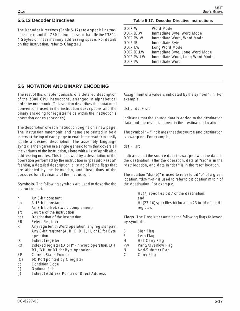
5-17
Z380™
USER'S MANUALZILOG
DC-8297-03
5.5.12 Decoder Directives
The Decoder Directives (Table 5-17) are a special instruc-tions to expand the Z80 instruction set to handle the Z380’s4 Gbytes of linear memory addressing space. For detailson this instruction, refer to Chapter 3.
Table 5-17. Decoder Directive Instructions
DDIR W Word ModeDDIR IB,W Immediate Byte, Word ModeDDIR IW,W Immediate Word, Word ModeDDIR IB Immediate ByteDDIR LW Long Word ModeDDIR IB,LW Immediate Byte, Long Word ModeDDIR IW,LW Immediate Word, Long Word ModeDDIR IW Immediate Word
5.6 NOTATION AND BINARY ENCODING
The rest of this chapter consists of a detailed descriptionof the Z380 CPU instructions, arranged in alphabeticalorder by mnemonic. This section describes the notationalconventions used in the instruction descriptions and thebinary encoding for register fields within the instruction’soperation codes (opcodes).
The description of each instruction begins on a new page.The instruction mnemonic and name are printed in boldletters at the top of each page to enable the reader to easilylocate a desired description. The assembly languagesyntax is then given in a single generic form that covers allthe variants of the instruction, along with a list of applicableaddressing modes. This is followed by a description of theoperation performed by the instruction in “pseudo Pascal”fashion, a detailed description, a listing of all the flags thatare affected by the instruction, and illustrations of theopcodes for all variants of the instruction.
Symbols. The following symbols are used to describe theinstruction set.
n An 8-bit constantnn A 16-bit constantd An 8-bit offset. (two’s complement)src Source of the instructiondst Destination of the instructionSR Select RegisterR Any register. In Word operation, any register pair.
Any 8-bit register (A, B, C, D, E, H, or L) for Byteoperation.
IR Indirect registerRX Indexed register (IX or IY) in Word operation, IXH,
IXL, IYH, or IYL for Byte operation.SP Current Stack Pointer(C) I/O Port pointed by C registercc Condition Code[ ] Optional field( ) Indirect Address Pointer or Direct Address
Assignment of a value is indicated by the symbol "←”. Forexample,
dst ← dst + src
indicates that the source data is added to the destinationdata and the result is stored in the destination location.
The symbol “↔” indicates that the source and destinationis swapping. For example,
dst ↔ src
indicates that the source data is swapped with the data inthe destination; after the operation, data at “src” is in the“dst” location, and data in “dst “ is in the “src” location.
The notation “dst (b)” is used to refer to bit “b” of a givenlocation, “dst(m-n)” is used to refer to bit location m to n ofthe destination. For example,
HL(7) specifies bit 7 of the destination.andHL(23-16) specifies bit location 23 to 16 of the HLregister.
Flags. The F register contains the following flags followedby symbols.
S Sign FlagZ Zero FlagH Half Carry FlagP/V Parity/Overflow FlagN Add/Subtract FlagC Carry Flag

5-18
Z380™
USER'S MANUAL
DC-8297-03
ZILOG
5.6 NOTATION AND BINARY ENCODING (Continued)
Condition Codes. The following symbols describe thecondition codes.
Z Zero*NZ Not Zero*C Carry*NC No Carry*S SignNS No SignNV No OverflowV OverflowPE Parity EvenPO Parity OddP PositiveM Minus
*Abbreviated set
Field Encoding. For opcode binary format in the Tables,use the following convention:
For example, to get the opcode format on the instructionLD (IX+12h), C
First, find out the entry for “LD (XY+d),R”. That entry hasa opcode format of
11 y11 101 01 110 -r- ← d →
On the bottom of the each instruction, there are the fieldencodings, if applicable. For the cases which call out “perconvention,” then use the following encoding:
r Reg000 B001 C010 D011 E100 H101 L111 A
To form the opcode, first, look for the “y” field value for IXregister, which is 0.
Then find “r” field value for the C register, which is 001.Replace “y” and “r” field with the value from the table,replace “d” value with the real number. The results being:
76 543 210 HEX11 011 101 DD01 110 001 7100 010 010 21
5.7 EXECUTION TIME
i in the execution time column indicates an I/O readoperation. The time required for a read operation is shownin the Table 5-18 below.
o in the execution time column indicates an I/O writeoperation. The time required for a write operation is shownin the Table 5-18 below.
All entries in the table below assume no wait states. Thenumber of wait states per operation must be added tothese numbers.
Table 5-18 details the execution time for each instructionencoding. All execution times are for instruction executiononly. Clock cycles required for fetch and decode are notincluded because most of the time the clocks required forthese operations occur in parallel with execution of theprevious instruction(s).
r in the execution time column indicates a memory readoperation. The time required for a read operation is shownin the Table 5-18 below.
w in the execution time column indicates a memory writeoperation. The time required for a write operation is shownin the Table 5-18 below.

5-19
Z380™
USER'S MANUALZILOG
DC-8297-03
Table 5-18. Execution Time
Operation Byte Word Word Long Long Long Long Long
Sequence B W B/B W/W W/B/B B/W/B B/B/W B/B/B/BMemory Read 3-4 3-4 5-6 5-6 7-8 7-8 7-8 9-10Memory Write 0-1 0-1 2-3 2-3 4-5 4-5 4-5 6-7Internal I/O Read 3-4 N/A N/A N/A N/A N/A N/A N/A
Internal I/O Write 0-1 N/A N/A N/A N/A N/A N/A N/A1X External I/O Read 4-5 4-5 N/A N/A N/A N/A N/A N/A1X External I/O Write 1-2 1-2 N/A N/A N/A N/A N/A N/A2X External I/O Read 9-11 9-11 N/A N/A N/A N/A N/A N/A2X External I/O Write 1-3 1-3 N/A N/A N/A N/A N/A N/A
4X External I/O Read 17-21 17-21 N/A N/A N/A N/A N/A N/A4X External I/O Write 1-5 1-5 N/A N/A N/A N/A N/A N/A6X External I/O Read 25-31 25-31 N/A N/A N/A N/A N/A N/A6X External I/O Write 1-7 1-7 N/A N/A N/A N/A N/A N/A8X External I/O Read 33-41 33-41 N/A N/A N/A N/A N/A N/A8X External I/O Write 1-9 1-9 N/A N/A N/A N/A N/A N/A
Note: Units are in Clocks. “N/A” is not applicable for that particular transaction.

5-20
Z380™
USER'S MANUAL
DC-8297-03
ZILOG
ADCADD WITH CARRY (BYTE)
ADC A,src src = R, RX, IM, IR, X
Operation: A ← A + src + C
The source operand together with the Carry flag is added to the accumulator and the sumis stored in the accumulator. The contents of the source is unaffected. Two’s complementaddition is performed.
Flags: S: Set if the result is negative; cleared otherwiseZ: Set if the result is zero; cleared otherwiseH: Set if there is a carry from bit 3 of the result; cleared otherwiseV: Set if arithmetic overflow occurs, that is, if both operands cleared otherwiseN: ClearedC: Set if there is a carry from the most significant bit of the result; cleared otherwise
Addressing ExecuteMode Syntax Instruction Format Time NoteR: ADC A,R 10001-r- 2RX: ADC A,RX 11y11101 1000110w 2IM: ADC A,n 11001110 —n— 2IR: ADC A,(HL) 10001110 2+rX: ADC A,(XY+d) 11y11101 10001110—d— 4+r I
Field Encodings: r: per conventiony: 0 for IX, 1 for IYw: 0 for high byte, 1 for low byte

5-21
Z380™
USER'S MANUALZILOG
DC-8297-03
ADCADD WITH CARRY (WORD)
ADC HL,src dst = HLsrc = BC, DE, HL, SP
Operation: HL(15-0) ← HL(15-0) + src(15-0) + C
The source operand together with the Carry flag is added to the HL register and the sum isstored in the HL register. The contents of the source are unaffected. Two’s complementaddition is performed.
Flags: S: Set if the result is negative; cleared otherwiseZ: Set if the result is zero; cleared otherwiseH: Set if there is a carry from bit 11 of the result; cleared otherwiseV: Set if arithmetic overflow occurs, that is, if both operands are of the same sign and the
result is of the opposite sign; cleared otherwiseN: ClearedC: Set if there is a carry from the most significant bit of the result; cleared otherwise
Addressing ExecuteMode Syntax Instruction Format Time NoteR: ADC HL,R 11101101 01rr1010 2
Field Encodings: rr: 00 for BC, 01 for DE, 10 for HL, 11 for SP

5-22
Z380™
USER'S MANUAL
DC-8297-03
ZILOG
ADCWADD WITH CARRY (WORD)
ADCW [HL,]src src = R, RX, IM, X
Operation: HL(15-0) ← HL(15-0) + src(15-0) + C
The source operand together with the Carry flag is added to the HL register and the sum isstored in the HL register. The contents of the source are unaffected. Two’s complementaddition is performed.
Flags: S: Set if the result is negative; cleared otherwiseZ: Set if the result is zero; cleared otherwiseH: Set if there is a carry from bit 11 of the result; cleared otherwiseV: Set if arithmetic overflow occurs, that is, if both operands are of the same sign and the
result is of the opposite sign; cleared otherwiseN: ClearedC: Set if there is a carry from the most significant bit of the result; cleared otherwise
Addressing ExecuteMode Syntax Instruction Format Time NoteR: ADCW [HL,]R 11101101 100011rr 2RX: ADCW [HL,]RX 11y11101 10001111 2IM: ADCW [HL,]nn 11101101 10001110 -n(low)- n(high)- 2X: ADCW [HL,](XY+d) 11y11101 11001110 ——d— 4+r I
Field Encodings: rr: 00 for BC, 01 for DE, 11 for HLy: 0 for IX, 1 for IY

5-23
Z380™
USER'S MANUALZILOG
DC-8297-03
ADDADD (BYTE)
ADD A,src src = R, RX, IM, IR, X
Operation: A ← A + src
The source operand is added to the accumulator and the sum is stored in the accumulator.The contents of the source are unaffected. Two’s complement addition is performed.
Flags: S: Set if the result is negative; cleared otherwiseZ: Set if the result is zero; cleared otherwiseH: Set if there is a carry from bit 3 of the result; cleared otherwiseV: Set if arithmetic overflow occurs, that is, if both operands are of the same sign and the
result is of the opposite sign; cleared otherwiseN: ClearedC: Set if there is a carry from the most significant bit of the result; cleared otherwise
Addressing ExecuteMode Syntax Instruction Format Time NoteR: ADD A,R 10000-r- 2RX: ADD A,RX 11y11101 1000010w 2IM: ADD A,n 11000110 ——n— 2IR: ADD A,(HL) 10000110 2+rX: ADD A,(XY+d) 11y11101 10000110 ——d— 4+r I
Field Encodings: r: per conventiony: 0 for IX, 1 for IYw: 0 for high byte, 1 for low byte

5-24
Z380™
USER'S MANUAL
DC-8297-03
ZILOG
ADDADD (WORD)
ADD dst,src dst = HL; src = BC, DE, HL, SP, DAor
dst = IX; src = BC, DE, IX, SPor
dst = IY; src = BC, DE, IY, SP
Operation: If (XM) then begindst(31-0) ← dst(31-0) + src(31-0)endelse begindst(15-0) ← dst(15-0) + src(15-0)end
The source operand is added to the destination and the sum is stored in the destination. Thecontents of the source are unaffected. Two’s complement addition is performed. Note thatthe length of the operand is controlled by the Extended/Native mode selection, which isconsistent with the manipulation of an address by the instruction.
Flags: S: UnaffectedZ: UnaffectedH: Set if there is a carry from bit 11 of the result; cleared otherwiseV: UnaffectedN: ClearedC: Set if there is a carry from the most significant bit of the result; cleared otherwise
Addressing ExecuteMode Syntax Instruction Format Time NoteR: ADD HL,R 00rr1001 2 XRX: ADD XY,R 11y11101 00rr1001 2 XDA: ADD HL,(nn) 11101101 11000110 -n(low)- n(high)- 2+r I, X
Field Encodings: rr: 00 for BC, 01 for DE, 10 for register to itself, 11 for SPy: 0 for IX, 1 for IY

5-25
Z380™
USER'S MANUALZILOG
DC-8297-03
ADDADD TO STACK POINTER (WORD)
ADD SP,srcsrc = IM
Operation: if (XM) then beginSP(31-0) ← SP(31-0) + src(31-0)end
else beginSP(15-0) ← SP(15-0) + src(15-0)
end
The source operand is added to the SP register and the sum is stored in the SP register. Thishas the effect of allocating or allocating space on the stack. Two’s complement addition isperformed.
Flags: S: UnaffectedZ: UnaffectedH: Set if there is a carry from bit 11 of the result; cleared otherwiseV: UnaffectedN: ClearedC: Set if there is a carry from the most significant bit of the result; cleared otherwise
Addressing ExecuteMode Syntax Instruction Format Time NoteIM: ADD SP,nn 11101101 10000010 -n(low)- -n(high) 2 I, X
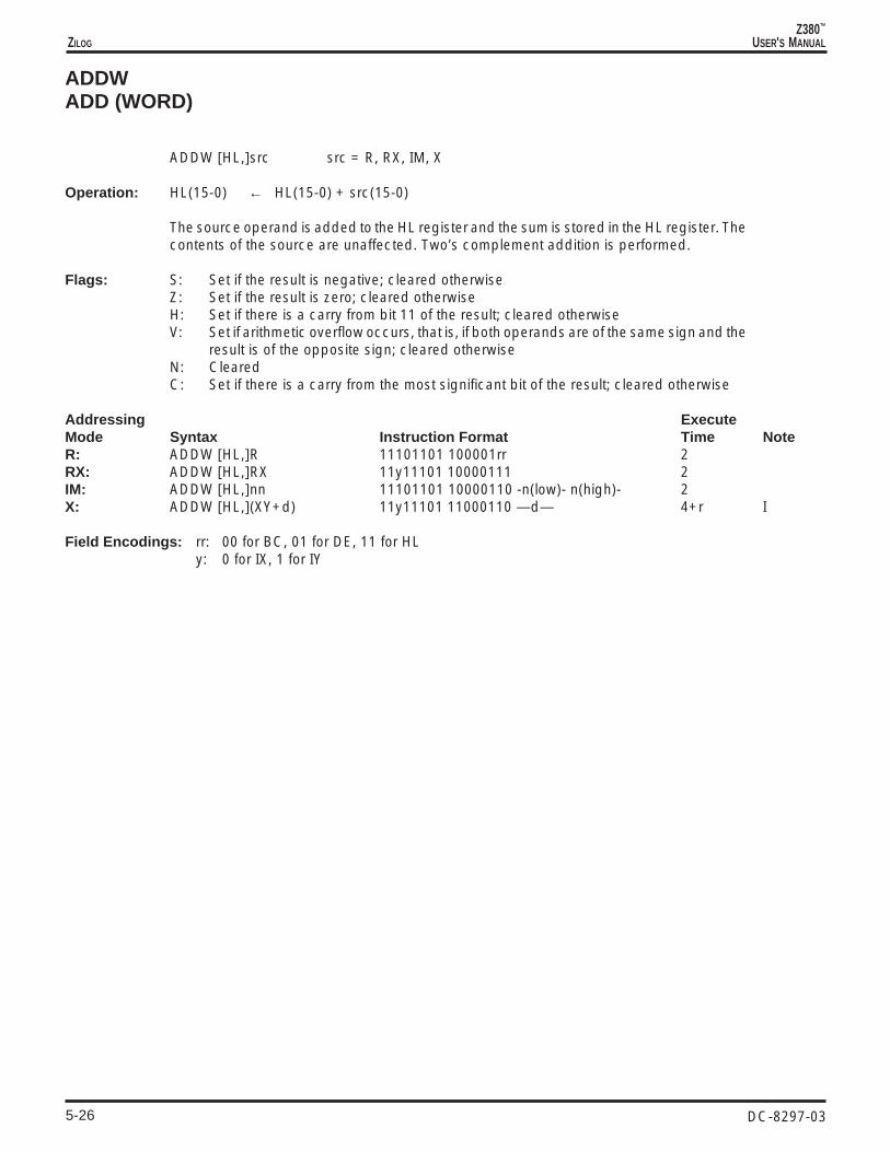
5-26
Z380™
USER'S MANUAL
DC-8297-03
ZILOG
ADDWADD (WORD)
ADDW [HL,]src src = R, RX, IM, X
Operation: HL(15-0) ← HL(15-0) + src(15-0)
The source operand is added to the HL register and the sum is stored in the HL register. Thecontents of the source are unaffected. Two’s complement addition is performed.
Flags: S: Set if the result is negative; cleared otherwiseZ: Set if the result is zero; cleared otherwiseH: Set if there is a carry from bit 11 of the result; cleared otherwiseV: Set if arithmetic overflow occurs, that is, if both operands are of the same sign and the
result is of the opposite sign; cleared otherwiseN: ClearedC: Set if there is a carry from the most significant bit of the result; cleared otherwise
Addressing ExecuteMode Syntax Instruction Format Time NoteR: ADDW [HL,]R 11101101 100001rr 2RX: ADDW [HL,]RX 11y11101 10000111 2IM: ADDW [HL,]nn 11101101 10000110 -n(low)- n(high)- 2X: ADDW [HL,](XY+d) 11y11101 11000110 —d— 4+r I
Field Encodings: rr: 00 for BC, 01 for DE, 11 for HLy: 0 for IX, 1 for IY

5-27
Z380™
USER'S MANUALZILOG
DC-8297-03
ANDAND (BYTE)
AND [A,]src src = R, RX, IM, IR, X
Operation : A ← A AND src
A logical AND operation is performed between the corresponding bits of the source operandand the accumulator and the result is stored in the accumulator. A 1 is stored wherever thecorresponding bits in the two operands are both 1s; otherwise a 0 is stored. The contentsof the source are unaffected.
Flags: S: Set if the most significant bit of the result is set; cleared otherwiseZ: Set if all bits of the result are zero; cleared otherwiseH: SetP: Set if the parity is even; cleared otherwiseN: ClearedC: Cleared
Addressing ExecuteMode Syntax Instruction Format Time NoteR: AND [A,]R 10100-r- 2RX: AND [A,]RX 11y11101 1010010w 2IM: AND [A,]n 11100110 ——n— 2IR: AND [A,](HL) 10100110 2+rX: AND [A,](XY+d) 11y11101 10100110——d— 4+r I
Field Encodings: r: per conventiony: 0 for IX, 1 for IYw: 0 for high byte, 1 for low byte

5-28
Z380™
USER'S MANUAL
DC-8297-03
ZILOG
ANDWAND (WORD)
ANDW [HL,]src src = R, RX, IM, X
Operation: HL(15-0) ← HL(15-0) AND src(15-0)
A logical AND operation is performed between the corresponding bits of the source operandand the HL register and the result is stored in the HL register. A 1 is stored wherever thecorresponding bits in the two operands are both 1s; otherwise a 0 is stored. The contentsof the source are unaffected.
Flags: S: Set if the most significant bit of the result is set; cleared otherwiseZ: Set if all bits of the result are zero; cleared otherwiseH: SetP: Set if the parity is even; cleared otherwiseN: ClearedC: Cleared
Addressing ExecuteMode Syntax Instruction Format Time NoteR: ANDW [HL,]R 11101101 101001rr 2RX: ANDW [HL,]RX 11y11101 10100111 2IM: ANDW [HL,]nn 1110110110100110 n(low)- n(high)- 2X: ANDW [HL,](XY+d) 11y11101 11100110 ——d— 4+r I
Field Encodings: rr: 00 for BC, 01 for DE, 11 for HLy: 0 for IX, 1 for IY

5-29
Z380™
USER'S MANUALZILOG
DC-8297-03
BITBIT TEST
BIT b,dst dst = R, IR, X
Operation: Z ← NOT dst(b)
The specified bit b within the destination operand is tested, and the Zero flag is set to 1 ifthe specified bit is 0, otherwise the Zero flag is cleared to 0. The contents of the destinationare unaffected. The bit to be tested is specified by a 3-bit field in the instruction; this fieldcontains the binary encoding for the bit number to be tested. The bit number b must bebetween 0 and 7.
Flags: S: UnaffectedZ: Set if the specified bit is zero; cleared otherwiseH: SetV: UnaffectedN: ClearedC: Unaffected
Addressing ExecuteMode Syntax Instruction Format Time NoteR: BIT b,R 11001011 01bbb-r- 2IR: BIT b,(HL) 11001011 01bbb110 2+rX: BIT b,(XY+d) 11y11101 11001011 ——d— 01bbb110 4+r I
Field Encodings: r: per conventiony: 0 for IX, 1 for IY
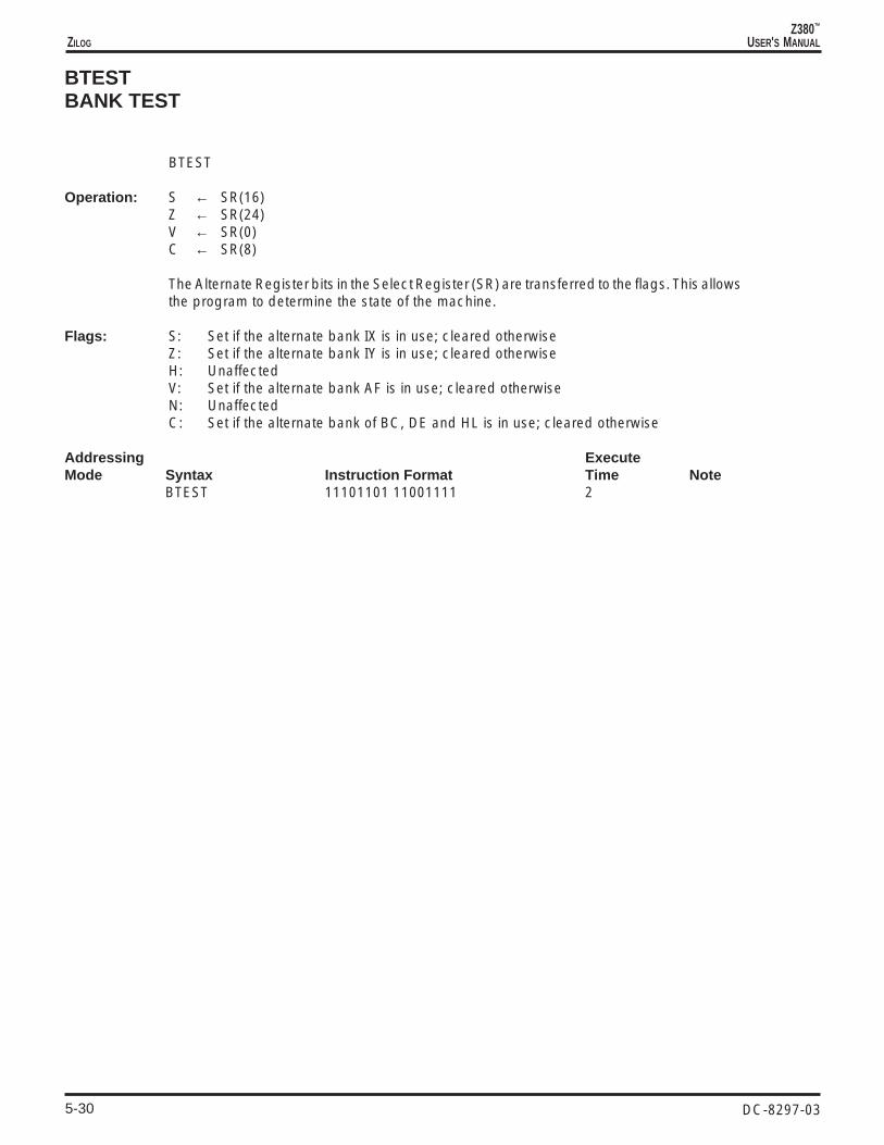
5-30
Z380™
USER'S MANUAL
DC-8297-03
ZILOG
BTESTBANK TEST
BTEST
Operation: S ← SR(16)Z ← SR(24)V ← SR(0)C ← SR(8)
The Alternate Register bits in the Select Register (SR) are transferred to the flags. This allowsthe program to determine the state of the machine.
Flags: S: Set if the alternate bank IX is in use; cleared otherwiseZ: Set if the alternate bank IY is in use; cleared otherwiseH: UnaffectedV: Set if the alternate bank AF is in use; cleared otherwiseN: UnaffectedC: Set if the alternate bank of BC, DE and HL is in use; cleared otherwise
Addressing ExecuteMode Syntax Instruction Format Time Note
BTEST 11101101 11001111 2

5-31
Z380™
USER'S MANUALZILOG
DC-8297-03
CALLCALL
CALL [cc,]dst dst = DA
Operation: if (cc is TRUE) then beginif (XM) then begin
SP ← SP - 4(SP) ← PC(7-0)(SP+1) ← PC(15-8)(SP+2) ← PC(23-16)(SP+3) ← PC(31-24)PC(31-0) ← dst(31-0)
else beginSP ← SP - 2(SP) ← PC(7-0)(SP+1) ← PC(15-8)PC(15-0) ← dst(15-0)end
end
A conditional Call transfers program control to the destination address if the setting of aselected flag satisfies the condition code “cc” specified in the instruction; an UnconditionalCall always transfers control to the destination address. The current contents of the ProgramCounter (PC) are pushed onto the top of the stack; the PC value used is the address of thefirst instruction byte following the Call instruction. The destination address is then loadedinto the PC and points to the first instruction of the called procedure. At the end of aprocedure a Return instruction (RET) can be used to return to the original program.
Each of the Zero, Carry, Sign, and Overflow Flags can be individually tested and a callperformed conditionally on the setting of the flag.
The operand is not enclosed in parentheses with the CALL instruction.
Flags: S: UnaffectedZ: UnaffectedH: UnaffectedV: UnaffectedN: UnaffectedC: Unaffected
Addressing ExecuteMode Syntax Instruction Format Time NoteDA: CALL CC,addr 11-cc100 -a(low)- -a(high) note I, X
CALL addr 11001101 -a(low)- -a(high) 4+w I, X
Field Encodings: cc: 000 for NZ, 001 for Z, 010 for NC, 011 for C,100 for PO or NV, 101 for PE or V, 110 for P or NS, 111 for M or S
Note: 2 if CC is false, 4+w if CC is true

5-32
Z380™
USER'S MANUAL
DC-8297-03
ZILOG
CALRCALL RELATIVE
CALR [cc,]dst dst = RA
Operation: if (cc is true) then begindst ← SIGN EXTEND dstif (XM) then begin
SP ← SP - 4(SP) ← PC(7-0)(SP+1) ← PC(15-8)(SP+2) ← PC(23-16)(SP+3) ← PC(31-24)PC(31-0) ← PC(31-0) + dst(31-0)end
else beginSP ← SP - 2(SP) ← PC(7-0)(SP+1) ← PC(15-8)PC(15-0) ← PC(15-0) + dst(15-0)end
end
A conditional Call transfers program control to the destination address if the setting of aselected flag satisfies the condition code “cc” specified in the instruction; an unconditionalcall always transfers control to the destination address. The current contents of the ProgramCounter (PC) are pushed onto the top of the stack; the PC value used is the address of thefirst instruction byte following the Call instruction. The destination address is then loaded intothe PC and points to the first instruction of the called procedure. At the end of a procedurea RETurn instruction is used to return to the original program. These instructions employeither an 8-bit, 16-bit, or 24-bit signed, two’s complement displacement from the PC topermit calls within the range of -126 to +129 bytes, –32,765 to +32,770 bytes or –8,388,604to +8,388,611 bytes from the location of this instruction.
Each of the Zero, Carry, Sign, and Overflow flags can be individually tested and a callperformed conditionally on the setting of the flag.
Flags: S: UnaffectedZ: UnaffectedH: UnaffectedV: UnaffectedN: UnaffectedC: Unaffected
Addressing ExecuteMode Syntax Instruction Format Time NoteRA: CALR CC,addr 11101101 11-cc100 —disp— note X
CALR addr 11101101 11001101 —disp— 4+w XCALR CC,addr 11011101 11-cc100 -d(low)- -d(high) note XCALR addr 11011101 11001101 -d(low)- -d(high) 4+w XCALR CC,addr 11111101 11-cc100 -d(low)- -d(mid)- -d(high) note XCALR addr 11111101 11001101 -d(low)- -d(mid) -d(high) 4+w X
Field Encodings: cc: 000 for NZ, 001 for Z, 010 for NC, 011 for C, 100 for PO or NV, 101 for PE or V,110 for P or NS, 111 for M or S
Note: 2 if CC is false, 4+w if CC is true

5-33
Z380™
USER'S MANUALZILOG
DC-8297-03
CCFCOMPLEMENT CARRY FLAG
CCF
Operation: C ← NOT C
The Carry flag is inverted.
Flags: S: UnaffectedZ: UnaffectedH: The previous state of the Carry flagV: UnaffectedN: ClearedC: Set if the Carry flag was clear before the operation; cleared otherwise
Addressing ExecuteMode Syntax Instruction Format Time Note
CCF 00111111 2

5-34
Z380™
USER'S MANUAL
DC-8297-03
ZILOG
CPCOMPARE (BYTE)
CP [A,]src src = R, RX, IM, IR, X
Operation: A – src
The source operand is compared with the accumulator and the flags are set accordingly.The contents of the accumulator and the source are unaffected. Two’s complementsubtraction is performed.
Flags: S: Set if the result is negative; cleared otherwiseZ: Set if the result is zero; cleared otherwiseH: Set if there is a borrow from bit 4 of the result; cleared otherwiseV: Set if arithmetic overflow occurs, that is, if the operands are of different signs and the
result is of the same sign as the source; cleared otherwiseN: SetC: Set if there is a borrow from the most significant bit of the result; cleared otherwise
Addressing ExecuteMode Syntax Instruction Format Time NoteR: CP [A,]R 10111-r- 2RX: CP [A,]RX 11y11101 1011110w 2IM: CP [A,]n 11111110 ——n— 2IR: CP [A,](HL) 10111110 2+rX: CP [A,](XY+d) 11y11101 10111110 ——d— 4+r I
Field Encodings: r: per conventiony: 0 for IX, 1 for IYw: 0 for high byte, 1 for low byte

5-35
Z380™
USER'S MANUALZILOG
DC-8297-03
CPWCOMPARE (WORD)
CPW [HL,]src src = R, RX, IM, X
Operation: HL(15-0) – src(15-0)
The source operand is compared with the HL register and the flags are set accordingly. Thecontents of the HL register and the source are unaffected. Two’s complement subtractionis performed.
Flags: S: Set if the result is negative; cleared otherwiseZ: Set if the result is zero; cleared otherwiseH: Set if there is a borrow from bit 12 of the result; cleared otherwiseV: Set if arithmetic overflow occurs, that is, if the operands are of different signs and the
result is of the same sign as the source; cleared otherwiseN: SetC: Set if there is a borrow from the most significant bit of the result; cleared otherwise
Addressing ExecuteMode Syntax Instruction Format Time NoteR: CPW [HL,]R 11101101 101111rr 2RX: CPW [HL,]RX 11y11101 10111111 2IM: CPW [HL,]nn 11101101 10111110 -n(low)- n(high)- 2X: CPW [HL,](XY+d) 11y11101 11111110 ——d— 4+r I
Field Encodings: rr: 00 for BC, 01 for DE, 11 for HLy: 0 for IX, 1 for IY

5-36
Z380™
USER'S MANUAL
DC-8297-03
ZILOG
CPDCOMPARE AND DECREMENT (BYTE)
CPD
Operation: A - (HL)if (XM) then begin
HL(31-0) ← HL(31-0) - 1end
else beginHL(15-0) ← HL(15-0) - 1end
BC(15-0) ← BC(15-0) - 1
This instruction is used for searching strings of byte data. The byte of data at the locationaddressed by the HL register is compared with the contents of the accumulator and the Signand Zero flags are set to reflect the result of the comparison. The contents of the accumulatorand the memory bytes are unaffected. Two’s complement subtraction is performed. Nextthe HL register is decremented by one, thus moving the pointer to the previous element inthe string. The BC register, used as a counter, is then decremented by one.
Flags: S: Set if the result is negative; cleared otherwiseZ: Set if the result is zero, indicating that the contents of the accumulator and the memory
byte are equal; cleared otherwiseH: Set if there is a borrow from bit 4 of the result; cleared otherwiseV: Set if the result of decrementing BC is not equal to zero; cleared otherwiseN: SetC: Unaffected
Addressing ExecuteMode Syntax Instruction Format Time Note
CPD 11101101 10101001 3+r X

5-37
Z380™
USER'S MANUALZILOG
DC-8297-03
CPDRCOMPARE, DECREMENT AND REPEAT (BYTE)
CPDR
Operation: Repeat until (BC=0 OR match) beginA - (HL)if (XM) then begin
HL(31-0) ← HL(31-0) - 1end
else beginHL(15-0) ← HL(15-0) - 1end
BC(15-0) ← BC(15-0) - 1end
This instruction is used for searching strings of byte data. The bytes of data starting at thelocation addressed by the HL register are compared with the contents of the accumulatoruntil either an exact match is found or the string length is exhausted becuase the BC registerhas decremented to zero. The Sign and Zero flags are set to reflect the result of thecomparison. The contents of the accumulator and the memory bytes are unaffected.Two’scomplement subtraction is performed.
After each comparison, the HL register is decremented by one, thus moving the pointer tothe previous element in the string.
The BC register, used as a counter, is then decremented by one. If the result of decrementingthe BC register is not zero and no match has been found, the process is repeated. If thecontents of the BC register are zero at the start of this instruction, a string length of 65,536is indicated.
This instruction can be interrupted after each execution of the basic operation. The PC valueat the start of this instruction is pushed onto the stack so that the instruction can be resumed.
Flags: S: Set if the last result is negative; cleared otherwiseZ: Set if the last result is zero, indicating a match; cleared otherwiseH: Set if there is a borrow from bit 4 of the last result; cleared otherwiseV: Set if the result of decrementing BC is not equal to zero; cleared otherwiseN: SetC: Unaffected
Addressing ExecuteMode Syntax Instruction Format Time Note
CPDR 11101101 10111001 (3+r)n X

5-38
Z380™
USER'S MANUAL
DC-8297-03
ZILOG
CPICOMPARE AND INCREMENT (BYTE)
CPI
Operation: A - (HL)if (XM) then begin
HL(31-0) ← HL(31-0) + 1end
else beginHL(15-0) ← HL(15-0) + 1end
BC(15-0) ← BC(15-0) - 1
This instruction is used for searching strings of byte data. The byte of data at the locationaddressed by the HL register is compared with the contents of the accumulator and the Signand Zero flags are set to reflect the result of the comparison. The contents of the accumulatorand the memory bytes are unaffected. Two’s complement subtraction is performed. Next theHL register is incremented by one, thus moving the pointer to the next element in the string.The BC register, used as a counter, is then decremented by one.
Flags: S: Set if the result is negative; cleared otherwiseZ: Set if the result is zero, indicating that the contents of the accumulator and the memorybyte are equal; cleared otherwiseH: Set if there is a borrow from bit 4 of the result; cleared otherwiseV: Set if the result of decrementing BC is not equal to zero; cleared otherwiseN: SetC: Unaffected
Addressing ExecuteMode Syntax Instruction Format Time Note
CPI 11101101 10100001 3+r X
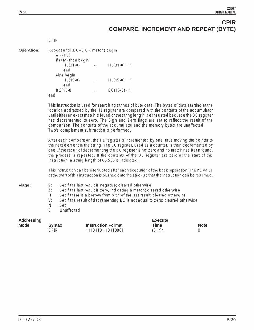
5-39
Z380™
USER'S MANUALZILOG
DC-8297-03
CPIRCOMPARE, INCREMENT AND REPEAT (BYTE)
CPIR
Operation: Repeat until (BC=0 OR match) beginA - (HL)if (XM) then begin
HL(31-0) ← HL(31-0) + 1end
else beginHL(15-0) ← HL(15-0) + 1end
BC(15-0) ← BC(15-0) - 1end
This instruction is used for searching strings of byte data. The bytes of data starting at thelocation addressed by the HL register are compared with the contents of the accumulatoruntil either an exact match is found or the string length is exhausted becuase the BC registerhas decremented to zero. The Sign and Zero flags are set to reflect the result of thecomparison. The contents of the accumulator and the memory bytes are unaffected.Two’s complement subtraction is performed.
After each comparison, the HL register is incremented by one, thus moving the pointer tothe next element in the string. The BC register, used as a counter, is then decremented byone. If the result of decrementing the BC register is not zero and no match has been found,the process is repeated. If the contents of the BC register are zero at the start of thisinstruction, a string length of 65,536 is indicated.
This instruction can be interrupted after each execution of the basic operation. The PC valueat the start of this instruction is pushed onto the stack so that the instruction can be resumed.
Flags: S: Set if the last result is negative; cleared otherwiseZ: Set if the last result is zero, indicating a match; cleared otherwiseH: Set if there is a borrow from bit 4 of the last result; cleared otherwiseV: Set if the result of decrementing BC is not equal to zero; cleared otherwiseN: SetC: Unaffected
Addressing ExecuteMode Syntax Instruction Format Time Note
CPIR 11101101 10110001 (3+r)n X

5-40
Z380™
USER'S MANUAL
DC-8297-03
ZILOG
CPLCOMPLEMENT ACCUMULATOR
CPL [A]
Operation: A ← NOT A
The contents of the accumulator are complemented (one's complement); all 1s are changedto 0 and vice-versa.
Flags: S: UnaffectedZ: UnaffectedH: SetV: UnaffectedN: SetC: Unaffected
Addressing ExecuteMode Syntax Instruction Format Time Note
CPL [A] 00101111 2

5-41
Z380™
USER'S MANUALZILOG
DC-8297-03
CPLWCOMPLEMENT HL REGISTER (WORD)
CPLW [HL]
Operation: HL(15-0) ← NOT HL(15-0)
The contents of the HL register are complemented (ones complement); all 1s are changedto 0 and vice-versa.
Flags: S: UnaffectedZ: UnaffectedH: SetV: UnaffectedN: SetC: Unaffected
Addressing ExecuteMode Syntax Instruction Format Time Note
CPLW [HL] 11011101 00101111 2

5-42
Z380™
USER'S MANUAL
DC-8297-03
ZILOG
DAADECIMAL ADJUST ACCUMULATOR
DAA
Operation: A ← Decimal Adjust A
The accumulator is adjusted to form two 4-bit BCD digits following a binary, two’scomplement addition or subtraction on two BCD-encoded bytes. The table below indicatesthe operation performed for addition (ADD, ADC, INC) or subtraction (SUB, SBC, DEC,NEG).
C Hex Value H Hex Value Number C HBefore Upper Digit Before Lower Digit Added After After
Operation DAA (Bits 7-4) DAA (Bits 3-0) to Byte DAA DAA
0 0-9 0 0-9 00 0 00 0-8 0 A-F 06 0 1
ADD 0 0-9 1 0-3 06 0 0ADC 0 A-F 0 0-9 60 1 0INC 0 9-F 0 A-F 66 1 1(N=0) 0 A-F 1 0-3 66 1 0
1 0-2 0 0-9 60 1 01 0-2 0 A-F 66 1 11 0-3 1 0-3 66 1 0
SUBSBC 0 0-9 0 0-9 00 0 0DEC 0 0-8 1 6-F FA 0 1NEG 1 7-F 0 0-9 A0 1 0(N=1) 1 6-F 1 6-F 9A 1 1
Flags: S: Set if the most significant bit of the result is set; cleared otherwiseZ: Set if the result is zero; cleared otherwiseH: See table aboveP: Set if the parity of the result is even; cleared otherwiseN: Not affectedC: See table above
Addressing ExecuteMode Syntax Instruction Format Time Note
DAA 00100111 3

5-43
Z380™
USER'S MANUALZILOG
DC-8297-03
DDIRDECODER DIRECTIVE
DDIR mode mode = W or LW, IB or IW
Operation: None, decoder directive only
This is not an instruction, but rather a directive to the instruction decoder.
The instruction decoder may be directed to fetch an additional byte or word of immediatedata or address with the instruction, as well as tagging the instruction for execution in eitherWord or Long Word mode. All eight combinations of the two options are supported, as shownin the encoding below. Instructions which do not support decoder directives are assembledby the instruction decoder as if the decoder directive were not present.
The IB decoder directive causes the decoder to fetch an additional byte immediately afterthe existing immediate data or direct address, and in front of any trailing opcode bytes (withinstructions starting with DD-CB or FD-CB, for example).
Likewise, the IW decoder directive causes the decoder to fetch an additional wordimmediately after the existing immediate data or direct address, and in front of any trailingopcode bytes.
Byte ordering within the instruction follows the usual convention; least significant byte first,followed by more significant bytes. More-significant immediate data or direct address bytesnot specified in the instruction are taken as all zeros by the processor.
The W decoder directive causes the instruction decoder to tag the instruction for executionin Word mode. This is useful while the Long Word (LW) bit in the Select Register (SR) is set,but 16-bit data manipulation is required for this instruction.
The LW decoder directive causes the instruction decoder to tag the instruction for executionin Long Word mode. This is useful while the LW bit in the SR is cleared, but 32-bit datamanipulation is required for this instruction.
Flags: S: UnaffectedZ: UnaffectedH: UnaffectedV: UnaffectedN: UnaffectedC: Unaffected
Addressing ExecuteMode Syntax Instruction Format Time Note
DDIR mode 11w11101 110000im 0
Field Encodings: wim: 000 W Word mode001 IB,W Immediate byte, Word mode010 IW,W Immediate word, Word mode011 IB Immediate byte100 LW Long Word mode101 IB,LW Immediate byte, Long Word mode110 IW,LW Immediate word, Long Word mode111 IW Immediate word

5-44
Z380™
USER'S MANUAL
DC-8297-03
ZILOG
DECDECREMENT (BYTE)
DEC dst dst = R, RX, IR, X
Operation: dst ← dst – 1
The destination operand is decremented by one and the result is stored in the destination.Two’s complement subtraction is performed.
Flags: S: Set if the result is negative; cleared otherwiseZ: Set if the result is zero; cleared otherwiseH: Set if there is a borrow from bit 4 of the result; cleared otherwiseV: Set if arithmetic overflow occurs, that is, if the destination was 80H; cleared otherwiseN: SetC: Unaffected
Addressing ExecuteMode Syntax Instruction Format Time NoteR: DEC R 00-r-101 noteRX: DEC RX 11y11101 0010w101 2IR: DEC (HL) 00110101 2+r+wX: DEC (XY+d) 11y11101 00110101 ——d— 4+r+w I
Field Encodings: r: per conventiony: 0 for IX, 1 for IYw: 0 for high byte, 1 for low byte
Note: 2 for accumulator, 3 for any other register

5-45
Z380™
USER'S MANUALZILOG
DC-8297-03
DEC[W]DECREMENT (WORD)
DEC[W] dstdst = R, RX
Operation: if (XM) then begindst(31-0) ← dst(31-0) - 1end
else begindst(15-0) ← dst(15-0) - 1end
The destination operand is decremented by one and the result is stored in the destination.Two’s complement subtraction is performed. Note that the length of the operand iscontrolled by the Extended/Native mode selection, which is consistent with the manipulationof an address by the instruction.
Flags: S: UnaffectedZ: UnaffectedH: UnaffectedV: UnaffectedN: UnaffectedC: Unaffected
Addressing ExecuteMode Syntax Instruction Format Time NoteR: DEC[W] R 00rr1011 2 XRX: DEC[W] RX 11y11101 00101011 2 X
Field Encodings: rr: 00 for BC, 01 for DE, 10 for HL, 11 for SPy: 0 for IX, 1 for IY

5-46
Z380™
USER'S MANUAL
DC-8297-03
ZILOG
DIDISABLE INTERRUPTS
DI [n]
Operation: if (n is present) then beginfor i=1 to 4 begin
if (n(i) = 1) then beginIER(i-1) ← 0end
endif (n(0) = 1) then begin
SR(5) ← 0end
endelse begin
SR(5) ← 0end
If an argument is present, disable the selected interrupts by clearing the appropriate enablebits in the Interrupt Enable Register, and then clear the Interrupt Enable Flag (IEF1) in theSelect Register (SR) if the least-significant bit of the argument is set, disabling maskableinterrupts. Bits 7-5 of the argument are ignored.
If no argument is present, IEF1 in the SR is set to 0, disabling maskable interrupts.
Note that during execution of this instruction the maskable interrupts are not sampled.
Flags: S: UnaffectedZ: UnaffectedH: UnaffectedV: UnaffectedN: UnaffectedC: Unaffected
Addressing ExecuteMode Syntax Instruction Format Time Note
DI 11110011 2DI n 11011101 11110011 —n—— 2

5-47
Z380™
USER'S MANUALZILOG
DC-8297-03
DIVUWDIVIDE UNSIGNED (WORD)
DIVUW [HL,]src src = R, RX, IM, X
Operation: HL(15-0) ← HL / srcHL(31-16) ← remainder
The contents of the the HL register (dividend) are divided by the source operand (divisor)and the quotient is stored in the lower word of the HL register; the remainder is stored in theupper word of the HL register. The contents of the source are unaffected. Both operands aretreated as unsigned, binary integers. There are three possible outcomes of the DIVUWinstruction, depending on the division and the resulting quotient:
Case 1: If the quotient is less than 65536, then the quotient is left in the HL register, theOverflow and Sign flags are cleared to 0, and the Zero flag is set according to the value ofthe quotient.
Case 2: If the divisor is zero, the HL register is unchanged, the Zero and Overflow flags areset to 1, and the Sign flag is cleared to 0.
Case 3: If the quotient is greater than or equal to 65536, the HL register is unchanged, theOverflow flag is set to 1, and the Sign and Zero flags are cleared to 0.
Flags: S: ClearedZ: Set if the quotient or divisor is zero; cleared otherwiseH: UnaffectedV: Set if the divisor is zero or if the computed quotient is greater than or equal to 65536;
cleared otherwiseN: UnaffectedC: Unaffected
Addressing ExecuteMode Syntax Instruction Format Time NoteR: DIVUW [HL,]R 11101101 11001011 101110rr 20RX: DIVUW [HL,]RX 11101101 11001011 1011110y 20IM: DIVUW [HL,]nn 11101101 11001011 10111111 -n(low)- -n(high) 20X: DIVUW [HL,](XY+d) 11y11101 11001011 ——d— 10111010 22+r I
Field Encodings: rr: 00 for BC, 01 for DE, 11 for HLy: 0 for IX, 1 for IY

5-48
Z380™
USER'S MANUAL
DC-8297-03
ZILOG
DJNZDECREMENT AND JUMP IF NON-ZERO
DJNZ dst dst = RA
Operation: B ← B-1If (B <> 0) then begin
dst ← SIGN EXTEND dstif (XM) then begin
PC(31-0) ← PC(31-0) + dst(31-0)end
else beginPC(15-0) ← PC(15-0) + dst(15-0)end
end
The B register is decremented by one. If the result is non-zero, then the destination addressis calculated and then loaded into the Program Counter (PC). Control then passes to theinstruction whose address is pointed to by the PC. When the B register reaches zero, controlfalls through to the instruction following DJNZ. This instruction provides a simple method ofloop control.
The destination address is calculated using Relative addressing. The displacement in theinstruction is added to the PC; the PC value used is the address of the instruction followingthe DJNZ instruction.
These instructions employ either an 8-bit, 16-bit, or 24-bit signed, two’s complementdisplacement from the PC to permit jumps within a range of -126 to +129 bytes, -32,765 to+32,770 bytes, or -8,388,604 to +8,388,611 bytes from the location of this instruction.
Flags: S: UnaffectedZ: UnaffectedH: UnaffectedV: UnaffectedN: UnaffectedC: Unaffected
Addressing ExecuteMode Syntax Instruction Format Time NoteRA: DJNZ addr 00010000 —disp— note X
DJNZ addr 11011101 00010000 -d(low)- -d(high) note XDJNZ addr 11111101 00010000 -d(low)- -d(mid)- -d(high) note X
Note: 3 if branch not taken, 4 if branch taken

5-49
Z380™
USER'S MANUALZILOG
DC-8297-03
EIENABLE INTERRUPTS
EI [n]
Operation: if (n is present) then beginfor i=1 to 4 begin
if (n(i) = 1) then beginIER(i-1) ← 1end
endif (n(0) = 1) then begin
SR(5) ← 1end
endelse begin
SR(5) ← 1end
If an argument is present, enable the selected interrupts by setting the appropriate enablebits in the Interrupt Enable Register, and then set the Interrupt Enable Flag (IEF1) in theSelect Register (SR) if the least-significant bit of the argument is set, enabling maskableinterrupts. Bits 7-5 of the argument are ignored.
If no argument is present, IEF1 in the SR is set to 1, enabling maskable interrupts.
Note that during the execution of this instruction and the following instruction, maskableinterrupts are not sampled.
Flags: S: UnaffectedZ: UnaffectedH: UnaffectedV: UnaffectedN: UnaffectedC: Unaffected
Addressing ExecuteMode Syntax Instruction Format Time Note
EI 11111011 2EI n 11011101 11111011 —n—— 2

5-50
Z380™
USER'S MANUAL
DC-8297-03
ZILOG
EXEXCHANGE ACCUMULATOR/FLAG WITH ALTERNATE BANK
EX AF,AF’
Operation: SR(0) ← NOT SR(0)
Bit 0 of the Select Register (SR), which controls the selection of primary or alternate bankfor the accumulator and flag register, is complemented, thus effectively exchanging theaccumulator and flag registers between the two banks.
Flags: S: Value in F’Z: Value in F’H: Value in F’V: Value in F’N: Value in F’C: Value in F’
Addressing ExecuteMode Syntax Instruction Format Time Note
EX AF,AF’ 00001000 3

5-51
Z380™
USER'S MANUALZILOG
DC-8297-03
EXEXCHANGE ADDRESSING REGISTER WITH TOP OF STACK
EX (SP),dst dst = HL, IX, IY
Operation: if (LW) then begin(SP+3) ↔ dst(31-24)(SP+2) ↔ dst(23-16)end
(SP+1) ↔ dst(15-8)(SP) ↔ dst(7-0)
The contents of the destination register are exchanged with the top of the stack. In LongWord mode this exchange is two words; otherwise it is one word.
Flags: S: UnaffectedZ: UnaffectedH: UnaffectedV: UnaffectedN: UnaffectedC: Unaffected
Addressing ExecuteMode Syntax Instruction Format Time NoteR: EX (SP),HL 11100011 3+r+w L
EX (SP),XY 11y11101 11100011 3+r+w L
Field Encodings: y: 0 for IX, 1 for IY

5-52
Z380™
USER'S MANUAL
DC-8297-03
ZILOG
EXEXCHANGE REGISTER (WORD)
EX dst,src dst = R, RXsrc = R, RX
Operation: if (LW) then begindst(31-0) ↔ src(31-0)end
else begindst(15-0) ↔ src(15-0)end
The contents of the destination are exchanged with the contents of the source.
Flags: S: UnaffectedZ: UnaffectedH: UnaffectedV: UnaffectedN: UnaffectedC: Unaffected
Addressing ExecuteMode Syntax Instruction Format Time NoteR: EX BC,DE 11101101 00000101 3 L
EX BC,HL 11101101 00001101 3 LEX DE,HL 11101011 3 L
RX: EX R,RX 11101101 00rry011 3 LEX IX,IY 11101101 00101011 3 L
Field Encodings: rr: 00 for BC, 01 for DE, 11 for HLy: 0 for IX, 1 for IY

5-53
Z380™
USER'S MANUALZILOG
DC-8297-03
EXEXCHANGE REGISTER WITH ALTERNATE REGISTER (BYTE)
EX dst,src src = R
Operation: dst ↔ src
The contents of the destination are exchanged with the contents of the source, where thedestination is a register in the primary bank and the source is the corresponding register inthe alternate bank
Flags: S: UnaffectedZ: UnaffectedH: UnaffectedV: UnaffectedN: UnaffectedC: Unaffected
Addressing ExecuteMode Syntax Instruction Format Time NoteR: EX R,R’ 11001011 00110-r- 3
Field Encoding: r: per convention

5-54
Z380™
USER'S MANUAL
DC-8297-03
ZILOG
EXEXCHANGE REGISTER WITH ALTERNATE REGISTER (WORD)
EX dst,src src = R, RX
Operation: if (LW) then begindst(31-0) ↔ src(31-0)end
else begindst(15-0) ↔ src(15-0)end
The contents of the destination are exchanged with the contents of the source, where thedestination is a word register in the primary bank and the source is the corresponding wordregister in the alternate bank.
Flags: S: UnaffectedZ: UnaffectedH: UnaffectedV: UnaffectedN: UnaffectedC: Unaffected
Addressing ExecuteMode Syntax Instruction Format Time NoteR: EX R,R’ 11101101 11001011 001100rr 3 LRX: EX RX,RX’ 11101101 11001011 0011010y 3 L
Field Encodings: rr: 00 for BC, 01 for DE, 11 for HLy: 0 for IX, 1 for IY

5-55
Z380™
USER'S MANUALZILOG
DC-8297-03
EXEXCHANGE WITH ACCUMULATOR
EX A,src src = R, IR
Operation: dst ↔ src
The contents of the accumulator are exchanged with the contents of the source.
Flags: S: UnaffectedZ: UnaffectedH: UnaffectedV: UnaffectedN: UnaffectedC: Unaffected
Addressing ExecuteMode Syntax Instruction Format Time NoteR: EX A,R 11101101 00-r-111 3IR: EX A,(HL) 11101101 00110111 3+r+w
Field Encodings: r: per convention

5-56
Z380™
USER'S MANUAL
DC-8297-03
ZILOG
EXALLEXCHANGE ALL REGISTERS WITH ALTERNATE BANK
EXALL
Operation: SR(24) ← NOT SR(24)SR(16) ← NOT SR(16)SR(8) ← NOT SR(8)
Bits 8, 16, and 24 of the Select Register (SR), which control the selection of primary oralternate bank for the BC, DE, HL, IX, and IY registers, are complemented, thus effectivelyexchanging the BC, DE, HL, IX, and IY registers between the two banks.
Flags: S: UnaffectedZ: UnaffectedH: UnaffectedV: UnaffectedN: UnaffectedC: Unaffected
Addressing ExecuteMode Syntax Instruction Format Time Note
EXALL 11101101 11011001 3

5-57
Z380™
USER'S MANUALZILOG
DC-8297-03
EXTSEXTEND SIGN (BYTE)
EXTS [A]
Operation: L ← Aif (A(7)=0) then begin
H ¨ 00hif (LW) then begin
HL(31-16) ← 0000hend
endelse begin
H ¨ FFhif (LW) then begin
HL(31-16) ← FFFFhend
end
The contents of the accumulator, considered as a signed, two’s complement integer, aresign-extended to 16 bits and the result is stored in the HL register. The contents of theaccumulator are unaffected. This instruction is useful for conversion of short signedoperands into longer signed operands.
Flags: S: UnaffectedZ: UnaffectedH: UnaffectedV: UnaffectedN: UnaffectedC: Unaffected
Addressing ExecuteMode Syntax Instruction Format Time Note
EXTS [A] 11101101 01100101 3 L

5-58
Z380™
USER'S MANUAL
DC-8297-03
ZILOG
EXTSWEXTEND SIGN (WORD)
EXTSW [HL]
Operation: If (HL(15)=0) then beginHL(31-16) ← 0000hend
else beginHL(31-16) ← FFFFhend
The contents of the low word of the HL register, considered as a signed, two's complementinteger, are sign-extended to 32 bits in the HL register. This instruction is useful forconversion of 16-bit signed operands into 32-bit signed operands.
Flags: S: UnaffectedZ: UnaffectedH: UnaffectedV: UnaffectedN: UnaffectedC: Unaffected
Addressing ExecuteMode Syntax Instruction Format Time Note
EXTSW [HL] 11101101 01110101 3

5-59
Z380™
USER'S MANUALZILOG
DC-8297-03
EXXEXCHANGE REGISTERS WITH ALTERNATE BANK
EXX
Operation: SR(8) ← NOT SR(8)
Bit 8 of the Select Register (SR), which controls the selection of primary or alternate bankfor the BC, DE, and HL registers, is complemented, thus effectively exchanging the BC, DE,and HL registers between the two banks.
Flags: S: UnaffectedZ: UnaffectedH: UnaffectedV: UnaffectedN: UnaffectedC: Unaffected
Addressing ExecuteMode Syntax Instruction Format Time Note
EXX 11011001 3

5-60
Z380™
USER'S MANUAL
DC-8297-03
ZILOG
EXXXEXCHANGE IX REGISTER WITH ALTERNATE BANK
EXXX
Operation: SR(16) ← NOT SR(16)
Bit 16 of the Select Register (SR), which controls the selection of primary or alternate bankfor the IX register, is complemented, thus effectively exchanging the IX register between thetwo banks.
Flags: S: UnaffectedZ: UnaffectedH: UnaffectedV: UnaffectedN: UnaffectedC: Unaffected
Addressing ExecuteMode Syntax Instruction Format Time Note
EXXX 11011101 11011001 3

5-61
Z380™
USER'S MANUALZILOG
DC-8297-03
EXXYEXCHANGE IY REGISTER WITH ALTERNATE BANK
EXXY
Operation: SR(24) ← NOT SR(24)
Bit 24 of the Select Register (SR), which controls the selection of primary or alternate bankfor the IY register, is complemented, thus effectively exchanging the IY register between thetwo banks.
Flags: S: UnaffectedZ: UnaffectedH: UnaffectedV: UnaffectedN: UnaffectedC: Unaffected
Addressing ExecuteMode Syntax Instruction Format Time Note
EXXY 11111101 11011001 3

5-62
Z380™
USER'S MANUAL
DC-8297-03
ZILOG
HALTHALT
HALT
Operation: CPU Halts
The CPU operation is suspended until either an interrupt request or reset request isreceived. This instruction is used to synchronize the CPU with external events, preservingits state until an interrupt or reset request is accepted. After an interrupt is serviced, theinstruction following HALT is executed. While the CPU is halted, memory refresh cycles stilloccur, and bus requests are honored. When this instruction is executed the signal /HALTis asserted and remains asserted until an interrupt or reset request is accepted.
Flags: S: UnaffectedZ: UnaffectedH: UnaffectedV: UnaffectedN: UnaffectedC: Unaffected
Addressing ExecuteMode Syntax Instruction Format Time Note
HALT 01110110 2

5-63
Z380™
USER'S MANUALZILOG
DC-8297-03
IMINTERRUPT MODE SELECT
IM p p = 0, 1, 2, 3
Operation: SR(4-3) ← p
The interrupt mode of operation is set to one of four modes. (See Chapter 6 for a descriptionof the various modes for responding to interrupts). The current interrupt mode can be readfrom the Select Register (SR).
Flags: S: UnaffectedZ: UnaffectedH: UnaffectedV: UnaffectedN: UnaffectedC: Unaffected
Addressing ExecuteMode Syntax Instruction Format Time Note
IM p 11101101 010pp110 4
Field Encodings: pp: 00 for Mode 0, 01 for Mode 3, 10 for Mode 1, 11 for Mode 2

5-64
Z380™
USER'S MANUAL
DC-8297-03
ZILOG
ININPUT (BYTE)
IN dst,(C) dst = R
Operation: dst ← (C)
The byte of data from the selected peripheral is loaded into the destination register. Duringthe I/O transaction, the contents of the 32-bit BC register are placed on the address bus.
Flags: S: Set if the input data is negative; cleared otherwiseZ: Set if the input data is zero; cleared otherwiseH: ClearedP: Set if the input data has even parity; cleared otherwiseN: ClearedC: Unaffected
Addressing ExecuteMode Syntax Instruction Format Time NoteR: IN R,(C) 11101101 01-r-000 2+i
Field Encodings: r: per convention

5-65
Z380™
USER'S MANUALZILOG
DC-8297-03
INWINPUT (WORD)
INW dst,(C) dst = R
Operation: dst(15-0) ← (C)
The word of data from the selected peripheral is loaded into the destination register. Duringthe I/O transaction, the contents of the 32-bit BC register are placed on the address bus.
Flags: S: Set if the input data is negative; cleared otherwiseZ: Set if the input data is zero; cleared otherwiseH: ClearedP: Set if the input data has even parity; cleared otherwiseN: ClearedC: Unaffected
Addressing ExecuteMode Syntax Instruction Format Time NoteR: INW R,(C) 11011101 01rrr000 2+i
Field Encodings: rrr: 000 for BC, 010 for DE, 111 for HL

5-66
Z380™
USER'S MANUAL
DC-8297-03
ZILOG
ININPUT ACCUMULATOR
IN A,(n)
Operation: A ← (n)
The byte of data from the selected peripheral is loaded into the accumulator. During theI/O transaction, the 8-bit peripheral address from the instruction is placed on the low byteof the address bus, the contents of the accumulator are placed on address lines A15-A8,and the high-order address lines are all zeros.
Flags: S: UnaffectedZ: UnaffectedH: UnaffectedV: UnaffectedN: UnaffectedC: Unaffected
Addressing ExecuteMode Syntax Instruction Format Time Note
IN A,(n) 11011011 ——n— 3+i

5-67
Z380™
USER'S MANUALZILOG
DC-8297-03
IN0INPUT (FROM PAGE 0)
IN0 dst,(n) dst = R
Operation: dst ← (n)
The byte of data from the selected on-chip peripheral is loaded into the destination register.No external I/O transaction will be generated as a result of this instruction, although the I/O address will appear on the address bus while this internal read is occurring. Theperipheral address is placed on the low byte of the address bus and zeros are placed onall other address lines. When the second opcode byte is 30h no data is stored in adestination; only the flags are updated.
Flags: S: Set if the input data is negative; cleared otherwiseZ: Set if the input data is zero; cleared otherwiseH: ClearedP: Set if the input data has even parity; cleared otherwiseN: ClearedC: Unaffected
Addressing ExecuteMode Syntax Instruction Format Time NoteR: IN0 R,(n) 11101101 00 -r- 000 ——n— 3+inone: IN0 (n 11101101 00110000 ——n— 3+i
Field Encodings: r: per convention

5-68
Z380™
USER'S MANUAL
DC-8297-03
ZILOG
INAINPUT DIRECT FROM PORT ADDRESS (BYTE)
INA A,(nn)
Operation: A ← (nn)
The byte of data from the selected peripheral is loaded into the accumulator. During theI/O transaction, the peripheral address from the instruction is placed on the address bus.Any bytes of address not specified in the instruction are driven on the address lines as allzeros.
Flags: S: UnaffectedZ: UnaffectedH: UnaffectedV: UnaffectedN: UnaffectedC: Unaffected
Addressing ExecuteMode Syntax Instruction Format Time Note
INA A,(nn) 11101101 11011011 -n(low)- -n(high) 3+i I

5-69
Z380™
USER'S MANUALZILOG
DC-8297-03
INAWINPUT DIRECT FROM PORT ADDRESS (WORD)
INAW HL,(nn)
Operation: HL(15-0) ← (nn)
The word of data from the selected peripheral is loaded into the HL register. During theI/O transaction, the peripheral address from the instruction is placed on the address bus.Any bytes of address not specified in the instruction are driven on the address lines as allzeros.
Flags: S: UnaffectedZ: UnaffectedH: UnaffectedV: UnaffectedN: UnaffectedC: Unaffected
Addressing ExecuteMode Syntax Instruction Format Time Note
INAW HL,(nn) 11111101 11011011 -n(low)- -n(high) 3+i I

5-70
Z380™
USER'S MANUAL
DC-8297-03
ZILOG
INCINCREMENT (BYTE)
INC dst dst = R, RX, IR, X
Operation: dst ← dst + 1
The destination operand is incremented by one and the sum is stored in the destination.Two’s complement addition is performed.
Flags: S: Set if the result is negative; cleared otherwiseZ: Set if the result is zero; cleared otherwiseH: Set if there is a carry from bit 3 of the result; cleared otherwiseV: Set if arithmetic overflow occurs, that is, if the destination was 7FH; cleared otherwiseN: ClearedC: Unaffected
Addressing ExecuteMode Syntax Instruction Format Time NoteR: INC R 00-r-100 noteRX: INC RX 11y11101 0010w100 2IR: INC (HL) 00110100 2+r+wX: INC (XY+d) 11y11101 00110100 ——d— 4+r+w I
Field Encodings: r: per conventiony: 0 for IX, 1 for IYw: 0 for high byte, 1 for low byte
Note: 2 for accumulator, 3 for any other register

5-71
Z380™
USER'S MANUALZILOG
DC-8297-03
INC[W]INCREMENT (WORD)
INC[W] dst dst = R, RX
Operation: if (XM) then begindst(31-0) < dst(31-0) + 1end
else begindst(15-0) ← dst(15-0) + 1end
The destination operand is incremented by one and the sum is stored in the destination.Two’s complement addition is performed. Note that the length of the operand is controlledby the Extended/Native mode selection, which is consistent with the manipulation of anaddress by the instruction.
Flags: S: UnaffectedZ: UnaffectedH: UnaffectedV: UnaffectedN: UnaffectedC: Unaffected
Addressing ExecuteMode Syntax Instruction Format Time NoteR: INC[W] R 00rr0011 2 XRX: INC[W] RX 11y11101 00100011 2 X
Field Encodings: rr: 00 for BC, 01 for DE, 10 for HL, 11 for SPy: 0 for IX, 1 for IY

5-72
Z380™
USER'S MANUAL
DC-8297-03
ZILOG
INDINPUT AND DECREMENT (BYTE)
IND
Operation: (HL) ← (C)B ← B – 1HL ← HL – 1
This instruction is used for block input of strings of data. During the I/O transaction the 32-bit BC register is placed on the address bus. Note that the B register contains the loop countfor this instruction so that A15-A8 are not useable as part of a fixed port address.
First the byte of data from the selected peripheral is loaded into the memory locationaddressed by the HL register. Then the B register, used as a counter, is decremented byone. The HL register is then decremented by one, thus moving the pointer to the nextdestination for the input.
Flags: S: UnaffectedZ: Set if the result of decrementing B is zero; cleared otherwiseH: UnaffectedV: UnaffectedN: SetC: Unaffected
Addressing ExecuteMode Syntax Instruction Format Time Note
IND 11101101 10101010 2+i+w

5-73
Z380™
USER'S MANUALZILOG
DC-8297-03
INDWINPUT AND DECREMENT (WORD)
INDW
Operation: (HL) ← (DE)BC(15-0) ← BC(15-0) – 1HL ← HL – 2
This instruction is used for block input of strings of data. During the I/O transaction the 32-bit DE register is placed on the address bus.
First the word of data from the selected peripheral is loaded into the memory locationaddressed by the HL register. Then the BC register, used as a counter, is decremented byone. The HL register is then decremented by two, thus moving the pointer to the nextdestination for the input.
Flags: S: UnaffectedZ: Set if the result of decrementing BC is zero; cleared otherwiseH: UnaffectedV: UnaffectedN: SetC: Unaffected
Addressing ExecuteMode Syntax Instruction Format Time Note
INDW 11101101 11101010 2+i+w

5-74
Z380™
USER'S MANUAL
DC-8297-03
ZILOG
INDRINPUT, DECREMENT AND REPEAT (BYTE)
INDR
Operation: repeat until (B=0) begin(HL) ← (C)B ← B – 1HL ← HL – 1end
This instruction is used for block input of strings of data. The string of input data from theselected peripheral is loaded into memory at consecutive addresses, starting with thelocation addressed by the HL register and decreasing. During the I/O transaction the32-bit BC register is placed on the address bus. Note that the B register contains the loopcount for this instruction so that A15-A8 are not useable as part of a fixedport address.
First the byte of data from the selected peripheral is loaded into the memory locationaddressed by the HL register. Then the B register, used as a counter, is decremented byone. The HL register is then decremented by one, thus moving the pointer to the nextdestination for the input. If the result of decrementing the B register is 0, the instruction isterminated, otherwise the sequence is repeated. If the B register contains 0 at the start ofthe execution of this instruction, 256 bytes are input.
This instruction can be interrupted after each execution of the basic operation. The ProgramCounter value at the start of this instruction is saved before the interrupt request is accepted,so that the instruction can be properly resumed.
Flags: S: UnaffectedZ: Set if the result of decrementing B is zero; cleared otherwiseH: UnaffectedV: UnaffectedN: SetC: Unaffected
Addressing ExecuteMode Syntax Instruction Format Time Note
INDR 11101101 10111010 n X (2+i+w)

5-75
Z380™
USER'S MANUALZILOG
DC-8297-03
INDRWINPUT, DECREMENT AND REPEAT (WORD)
INDRW
Operation: repeat until (BC=0) begin(HL) ← (DE)BC(15-0) ← BC(15-0) – 1HL ← HL – 2end
This instruction is used for block input of strings of data. The string of input data from theselected peripheral is loaded into memory at consecutive addresses, starting with thelocation addressed by the HL register and decreasing. During the I/O transaction the32-bit DE register is placed on the address bus.
First the BC register, used as a counter, is decremented by one. First the word of data fromthe selected peripheral is loaded into the memory location addressed by the HL register.Then the BC register, used as a counter, is decremented by one. The HL register is thendecremented by two, thus moving the pointer to the next destination for the input. If the resultof decrementing the BC register is 0, the instruction is terminated, otherwise the sequenceis repeated. If the BC register contains 0 at the start of the execution of this instruction, 65536bytes are input.
This instruction can be interrupted after each execution of the basic operation. The ProgramCounter value at the start of this instruction is saved before the interrupt request is accepted,so that the instruction can be properly resumed.
Flags: S: UnaffectedZ: Set if the result of decrementing BC is zero; cleared otherwiseH: UnaffectedV: UnaffectedN: SetC: Unaffected
Addressing ExecuteMode Syntax Instruction Format Time Note
INDRW 11101101 11111010 n X (2+i+w)

5-76
Z380™
USER'S MANUAL
DC-8297-03
ZILOG
INIINPUT AND INCREMENT (BYTE)
INI
Operation: (HL) ← (C)B ← B – 1HL ← HL + 1
This instruction is used for block input of strings of data. During the I/O transaction the 32-bit BC register is placed on the address bus. Note that the B register contains the loop countfor this instruction so that A15-A8 are not useable as part of a fixed port address.
First the byte of data from the selected peripheral is loaded into the memory locationaddressed by the HL register. Then the B register, used as a counter, is decremented byone. The HL register is then incremented by one, thus moving the pointer to the nextdestination for the input.
Flags: S: UnaffectedZ: Set if the result of decrementing B is zero; cleared otherwiseH: UnaffectedV: UnaffectedN: SetC: Unaffected
Addressing ExecuteMode Syntax Instruction Format Time Note
INI 11101101 10100010 2+i+w

5-77
Z380™
USER'S MANUALZILOG
DC-8297-03
INIWINPUT AND INCREMENT (WORD)
INIW
Operation: (HL) ← (DE)BC(15-0) ← BC(15-0) – 1HL ← HL + 2
This instruction is used for block input of strings of data.During the I/O transaction the 32-bit DE register is placed on the address bus.
First the word of data from the selected peripheral is loaded into the memory locationaddressed by the HL register. Then the BC register, used as a counter, is decremented byone. The HL register is then incremented by two, thus moving the pointer to the nextdestination for the input.
Flags: S: UnaffectedZ: Set if the result of decrementing BC is zero; cleared otherwiseH: UnaffectedV: UnaffectedN: SetC: Unaffected
Addressing ExecuteMode Syntax Instruction Format Time Note
INIW 11101101 11100010 2+i+w

5-78
Z380™
USER'S MANUAL
DC-8297-03
ZILOG
INIRINPUT, INCREMENT AND REPEAT (BYTE)
INIR
Operation: repeat until (B=0) begin(HL) ← (C)B ← B – 1HL ← HL + 1end
This instruction is used for block input of strings of data. The string of input data from theselected peripheral is loaded into memory at consecutive addresses, starting with thelocation addressed by the HL register and increasing. During the I/O transaction the 32-bitBC register is placed on the address bus. Note that the B register contains the loop countfor this instruction so that A(15-8) are not useable as part of a fixedport address.
First the byte of data from the selected peripheral is loaded into the memory locationaddressed by the HL register. Then the B register, used as a counter, is decremented byone. The HL register is then incremented by one, thus moving the pointer to the nextdestination for the input. If the result of decrementing the B register is 0, the instruction isterminated, otherwise the sequence is repeated. If the B register contains 0 at the start ofthe execution of this instruction, 256 bytes are input.
This instruction can be interrupted after each execution of the basic operation. The ProgramCounter value at the start of this instruction is saved before the interrupt request is accepted,so that the instruction can be properly resumed.
Flags: S: UnaffectedZ: Set if the result of decrementing B is zero; cleared otherwiseH: UnaffectedV: UnaffectedN: SetC: Unaffected
Addressing ExecuteMode Syntax Instruction Format Time Note
INIR 11101101 10110010 n X (2+i+w)

5-79
Z380™
USER'S MANUALZILOG
DC-8297-03
INIRWINPUT, INCREMENT AND REPEAT (WORD)
INIRW
Operation: repeat until (BC=0) begin(HL) ← (DE)BC(15-0) ← BC(15-0) – 1HL ← HL + 2end
This instruction is used for block input of strings of data. The string of input data from theselected peripheral is loaded into memory at consecutive addresses, starting with thelocation addressed by the HL register and increasing. During the I/O transaction the 32-bitDE register is placed on the address bus.
First the word of data from the selected peripheral is loaded into the memory locationaddressed by the HL register. Then the BC register, used as a counter, is decremented byone. The HL register is then incremented by two, thus moving the pointer to the nextdestination for the input. If the result of decrementing the BC register is 0, the instruction isterminated, otherwise the sequence is repeated. If the BC register contains 0 at the start ofthe execution of this instruction, 65536 bytes are input.
This instruction can be interrupted after each execution of the basic operation. The ProgramCounter value at the start of this instruction is saved before the interrupt request is accepted,so that the instruction can be properly resumed.
Flags: S: UnaffectedZ: Set if the result of decrementing BC is zero; cleared otherwiseH: UnaffectedV: UnaffectedN: SetC: Unaffected
Addressing ExecuteMode Syntax Instruction Format Time Note
INIRW 11101101 11110010 n X (2+i+w)

5-80
Z380™
USER'S MANUAL
DC-8297-03
ZILOG
JPJUMP
JP [cc,]dst dst = IR, DA
Operation: if (cc is TRUE) then beginif (XM) then begin
PC(31-0) ← dst(31-0)end
else beginPC(15-0) ← dst(15-0)end
end
A conditional jump transfers program control to the destination address if the setting of aselected flag satisfies the condition code “cc” specified in the instruction; an unconditionaljump always transfers control to the destination address. If the jump is taken, the ProgramCounter (PC) is loaded with the destination address; otherwise the instruction following theJump instruction is executed.
Each of the Zero, Carry, Sign, and Overflow flags can be individually tested and a jumpperformed conditionally on the setting of the flag.
When using DA mode with the JP instruction, the operand is not enclosed in parentheses.
Flags: S: UnaffectedZ: UnaffectedH: UnaffectedV: UnaffectedN: UnaffectedC: Unaffected
Addressing ExecuteMode Syntax Instruction Format Time NoteIR: JP (HL) 11101001 2 X
JP (XY) 11y11101 11101001 2 XDA: JP CC,addr 11-cc010 -a(low)- -a(high) 2 I, X
JP addr 11000011 -a(low)- -a(high) 2 I, X
Field Encodings: y: 0 for IX, 1 for IYcc: 000 for NZ, 001 for Z, 010 for NC, 011 for C, 100 for PO/NV, 101 for PE/V, 110 forP/NS,111 for M/S

5-81
Z380™
USER'S MANUALZILOG
DC-8297-03
JRJUMP RELATIVE
JR [cc,]dst dst = RA
Operation: if (cc is TRUE) then begindst ← SIGN EXTEND dstif (XM) then begin
PC(31-0) ← PC(31-0) + dst(31-0)end
else beginPC(15-0) ← PC(15-0) + dst(15-0)end
end
A conditional Jump transfers program control to the destination address if the setting of aselected flag satisfies the condition code “cc” specified in the instruction; an unconditionalJump always transfers control to the destination address. Either the Zero or Carry flag canbe tested for the conditional Jump. If the jump is taken, the Program Counter (PC) is loadedwith the destination address; otherwise the instruction following the Jump Relative instruc-tion is executed.
The destination address is calculated using relative addressing. The displacement in theinstruction is added to the PC value for the instruction following the JR instruction, not thevalue of the PC for the JR instruction.
These instructions employ either an 8-bit, 16-bit, or 24-bit signed, two’s complementdisplacement from the PC to permit jumps within a range of –126 to +129 bytes, –32,765 to+32,770 bytes, or –8,388,604 to +8,388,611 bytes from the location of this instruction.
Flags : S: UnaffectedZ: UnaffectedH: UnaffectedV: UnaffectedN: UnaffectedC: Unaffected
Addressing ExecuteMode Syntax Instruction Format Time NoteRA: JR CC,addr 001cc000 —disp— 2 X
JR addr 00011000 —disp— 2 XJR CC,addr 11011101 001cc000 -d(low)- -d(high) 2 XJR addr 11011101 00011000 -d(low)- -d(high) 2 XJR CC,addr 11111101 001cc000 -d(low)- -d(mid)- -d(high) 2 XJR addr 11111101 00011000 -d(low)- -d(mid)- -d(high) 2 X
Field Encodings: cc: 00 for NZ, 01 for Z, 10 for NC, 11 for C

5-82
Z380™
USER'S MANUAL
DC-8297-03
ZILOG
LDLOAD ACCUMULATOR
LD dst,src dst = Asrc = R, RX, IM, IR, DA, X
ordst = R, RX, IR, DA, Xsrc = A
Operation: dst ← src
The contents of the source are loaded into the destination.
Flags: S: UnaffectedZ: UnaffectedH: UnaffectedV: UnaffectedN: UnaffectedC: Unaffected
Load into AccunulatorAddressing ExecuteMode Syntax Instruction Format Time NoteR: LD A,R 01111-r- 2RX: LD A,RX 11y11101 0111110w 2IM: LD A,n 00111110 ——n— 2IR: LD A,(HL) 01111110 2+r
LD A,(IR) 000a1010 2+rDA: LD A,(nn) 00111010 -n(low)- -n(high) 3+r IX: LD A,(XY+d) 11y11101 01111110 ——d— 4+r I
Load from AccunulatorAddressing ExecuteMode Syntax Instruction Format Time NoteR: LD Rd,A 01-r-111 2RX: LD RX,A 11y11101 0110w111 2IR: LD (HL),A 01110111 3+w
LD (IR),A 000a0010 3+wDA: LD (nn),A 00110010 -n(low)- -n(high) 4+w IX: LD (XY+d),A 11y11101 01110111 ——d— 5+w I
Field Encodings: r: per conventiony: 0 for IX, 1 for IYw: 0 for high byte, 1 for low bytea: 0 for BC, 1 for DE

5-83
Z380™
USER'S MANUALZILOG
DC-8297-03
LDLOAD IMMEDIATE (BYTE)
LD dst,n dst = R, RX, IR, X
Operation: dst ← n
The byte of immediate data is loaded into the destination.
Flags: S: UnaffectedZ: UnaffectedH: UnaffectedV: UnaffectedN: UnaffectedC: Unaffected
Addressing ExecuteMode Syntax Instruction Format Time NoteR: LD R,n 00-r-110 ——n— 2RX: LD RX,n 11y11101 0010w110 ——n— 2IR: LD (HL),n 00110110 ——n— 3+wX: LD (XY+d),n 11y11101 00110110 ——d— ——n— 5+w I
Field Encodings: r: per conventiony: 0 for IX, 1 for IYw: 0 for high byte, 1 for low byte

5-84
Z380™
USER'S MANUAL
DC-8297-03
ZILOG
LDLOAD IMMEDIATE (WORD)
LD dst,nn dst = R, RX
Operation: if (LW) then begindst(31-0) ← nnend
else begindst(15-0) ← nnend
The word of immediate data is loaded into the destination.
Flags: S: UnaffectedZ: UnaffectedH: UnaffectedV: UnaffectedN: UnaffectedC: Unaffected
Addressing ExecuteMode Syntax Instruction Format Time NoteR: LD R,nn 00rr0001 -n(low)- -n(high) 2 I, LRX: LD RX,nn 11y11101 00100001 -n(low)- -n(high) 2 I, L
Field Encodings: rr: 00 for BC, 01 for DE, 10 for HLy: 0 for IX, 1 for IY

5-85
Z380™
USER'S MANUALZILOG
DC-8297-03
LDWLOAD IMMEDIATE (WORD)
LDW dst,nn dst = IR
Operation: if (LW) then begindst(31-0) ← nnend
else begindst(15-0) ← nn
end
The word of immediate data is loaded into the destination.
Flags: S: UnaffectedZ: UnaffectedH: UnaffectedV: UnaffectedN: UnaffectedC: Unaffected
Addressing ExecuteMode Syntax Instruction Format Time NoteIR: LDW (IR),nn 11101101 00pp0110 -n(low)- -n(high) 3+w I, L
Field Encodings: pp: 00 for BC, 01 for DE, 11 for HL

5-86
Z380™
USER'S MANUAL
DC-8297-03
ZILOG
LDLOAD REGISTER (BYTE)
LD dst,src dst = Rsrc = R, RX, IM, IR, X
ordst = R, RX, IR, Xsrc = R
Operation: dst ← src
The contents of the source are loaded into the destination.
Flags: S: UnaffectedZ: UnaffectedH: UnaffectedV: UnaffectedN: UnaffectedC: Unaffected
Load into RegisterAddressing ExecuteMode Syntax Instruction Format Time NoteR: LD Rd,Rs 01-rd-rs 2RX: LD Rd,RX 11y11101 01-ra10w 2
LD RXa,RXb 11y11101 0110a10b 2IM: LD R,n 00-r-110 ——n— 2IR: LD R,(HL) 01-r-110 5+wX: LD R,(XY+d) 11y11101 01-r-110 ——d— 7+w I
Load from RegisterAddressing ExecuteMode Syntax Instruction Format Time NoteRX: LD RX,Rs 11y11101 0110w-ra 2
LD RXa,RXb 11y11101 0110a10b 2IR: LD (HL),R 01110-r- 3+wX: LD (XY+d),R 11y11101 01110-r- ——d— 5+w I
Field Encodings: r: per conventionrd: per conventionrs: per conventiony: 0 for IX, 1 for IYw: 0 for high byte, 1 for low bytera: per convention, for A, B, C, D, E onlya: destination, 0 for high byte, 1 for low byteb: source, 0 for high byte, 1 for low byte
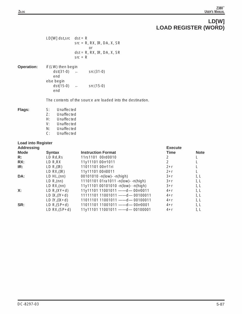
5-87
Z380™
USER'S MANUALZILOG
DC-8297-03
LD[W]LOAD REGISTER (WORD)
LD[W] dst,src dst = Rsrc = R, RX, IR, DA, X, SR
ordst = R, RX, IR, DA, X, SRsrc = R
Operation: if (LW) then begindst(31-0) ← src(31-0)end
else begindst(15-0) ← src(15-0)end
The contents of the source are loaded into the destination.
Flags: S: UnaffectedZ: UnaffectedH: UnaffectedV: UnaffectedN: UnaffectedC: Unaffected
Load into RegisterAddressing ExecuteMode Syntax Instruction Format Time NoteR: LD Rd,Rs 11rs1101 00rd0010 2 LRX: LD R,RX 11y11101 00rr1011 2 LIR: LD R,(IR) 11011101 00rr11ri 2+r L
LD RX,(IR) 11y11101 00ri0011 2+r LDA: LD HL,(nn) 00101010 -n(low)- -n(high) 3+r I, L
LD R,(nn) 11101101 01ra1011 -n(low)- -n(high) 3+r I, LLD RX,(nn) 11y11101 00101010 -n(low)- -n(high) 3+r I, L
X: LD R,(XY+d) 11y11101 11001011 ——d— 00rr0011 4+r I, LLD IX,(IY+d) 11111101 11001011 ——d— 00100011 4+r I, LLD IY,(IX+d) 11011101 11001011 ——d— 00100011 4+r I, L
SR: LD R,(SP+d) 11011101 11001011 ——d— 00rr0001 4+r I, LLD RX,(SP+d) 11y11101 11001011 ——d— 00100001 4+r I, L

5-88
Z380™
USER'S MANUAL
DC-8297-03
ZILOG
LD[W]LOAD REGISTER (WORD)
Load from RegisterAddressing ExecuteMode Syntax Instruction Format Time NoteRX: LD RX,R 11y11101 00rr0111 2 L
LD IX,IY 11011101 00100111 2 LLD IY,IX 11111101 00100111 2 L
IR: LD (IR),RR 11111101 00rr11ri 3+w LLD (IR),RX 11y11101 00ri0001 3+w L
DA: LD (nn),HL 00100010 -n(low)- -n(high) 4+w I, LLD (nn),R 11101101 01ra0011 -n(low)- -n(high) 4+w I, LLD (nn),RX 11y11101 00100010 -n(low)- -n(high) 4+w I, L
X: LD (XY+d),R 11y11101 11001011 ——d— 00rr1011 5+w I, LLD (IY+d),IX 11111101 11001011 ——d— 00101011 5+w I, LLD (IX+d),IY 11011101 11001011 ——d— 00101011 5+w I, L
SR: LD (SP+d),R 11011101 11001011 ——d— 00rr1001 5+w I, LLD (SP+d),XY 11y11101 11001011 ——d— 00101001 5+w I, L
Field Encodings: rs: 01 for DE, 10 for BC, 11 for HLrd: 00 for BC, 01 for DE, 11 for HLy: 0 for IX, 1 for IYrr: 00 for BC, 01 for DE, 11 for HLri: 00 for BC, 01 for DE, 11 for HLra: 00 for BC, 01 for DE, 10 for HL

5-89
Z380™
USER'S MANUALZILOG
DC-8297-03
LDLOAD STACK POINTER
LD dst,src dst = SPsrc = R, RX, IM, DA
ordst = DAsrc = SP
Operation: if (LW) then begindst(31-0) ← src(31-0)end
else begindst(15-0) ← src(15-0)end
The contents of the source are loaded into the destination.
Flags: S: UnaffectedZ: UnaffectedH: UnaffectedV: UnaffectedN: UnaffectedC: Unaffected
Load into Stack PointerAddressing ExecuteMode Syntax Instruction Format Time NoteR: LD SP,HL 11111001 2 LRX: LD SP,RX 11y11101 11111001 2 LIM: LD SP,nn 00110001 -n(low)- -n(high) 2 I, LDA: LD SP,(nn) 11101101 01111011 -n(low)- -n(high) 3+r I, L
Field Encodings: y: 0 for IX, 1 for IY
Load from Stack PointerAddressing ExecuteMode Syntax Instruction Format Time NoteDA: LD (nn),SP 11101101 01110011 -n(low)- -n(high) 4+w I, L

5-90
Z380™
USER'S MANUAL
DC-8297-03
ZILOG
LDLOAD FROM I OR R REGISTER (BYTE)
LD dst,src dst = Asrc = I, R
Operation: dst ← src
The contents of the source are loaded into the accumulator. The contents of the source arenot affected. The Sign and Zero flags are set according to the value of the data transferred;the Overflow flag is set according to the state of the interrupt enable. Note that if an interruptoccurs during execution of either of these instructions the Overflow flag reflects the priorstate of the interrupt enable. Also note that the R register does not contain the refreshaddress and is not modified by refresh transactions.
Flags: S: Set if the data loaded into the accumulator is negative; cleared otherwiseZ: Set if the data loaded into the accumulator is zero; cleared otherwiseH: ClearedV: Set when loading the accumulator if interrupts are enabled; cleared otherwiseN: ClearedC: Unaffected
Addressing ExecuteMode Syntax Instruction Format Time Note
LD A,I 11101101 01010111 2LD A,R 11101101 01011111 2

5-91
Z380™
USER'S MANUALZILOG
DC-8297-03
LDLOAD INTO I OR R REGISTER (BYTE)
LD dst,src dst = I, Rsrc = A
Operation: dst ← src
The contents of the accumulator are loaded into the destination. Note that the R register doesnot contain the refresh address and is not modified by refresh transactions.
Flags: S: UnaffectedZ: UnaffectedH: UnaffectedV: UnaffectedN: UnaffectedC: Unaffected
Addressing ExecuteMode Syntax Instruction Format Time NoteR: LD I,A 11101101 01000111 2
LD R,A 11101101 01001111 2

5-92
Z380™
USER'S MANUAL
DC-8297-03
ZILOG
LD[W]LOAD I REGISTER (WORD)
LD[W] dst,src dst = HLsrc = I ORdst = Isrc = HL
Operation: if (LW) then begindst(31-0) ← src(31-0)end
else begindst(15-0) ← src(15-0)end
The contents of the source are loaded into the destination
Flags: S: UnaffectedZ: UnaffectedH: UnaffectedV: UnaffectedN: UnaffectedC: Unaffected
Load from I RegisterAddressing ExecuteMode Syntax Instruction Format Time NoteR: LD[W] HL,I 11011101 01010111 2 L
Load into I RegisterAddressing ExecuteMode Syntax Instruction Format Time NoteR: LD[W] I,HL 11011101 01000111 2 L

5-93
Z380™
USER'S MANUALZILOG
DC-8297-03
LDCTLLOAD CONTROL REGISTER (BYTE)
LDCTL dst,src dst = DSR, XSR, YSRsrc = A, IM
ordst = Asrc = DSR, XSR, YSR
ordst = SRsrc = A, IM
Operation: if (dst = SR) then beginSR(31-24) ← srcSR(23-16) ← srcSR(15-8) ← srcend
else begindst ← srcend
The contents of the source are loaded into the destination.
Flags: S: UnaffectedZ: UnaffectedH: UnaffectedV: UnaffectedN: UnaffectedC: Unaffected
Load into Control RegisterAddressing ExecuteMode Syntax Instruction Format Time NoteR: LDCTL SR,A 11011101 11001000 4
LDCTL Rd,A 11qq1101 11011000 4IM: LDCTL SR,n 11011101 11001010 ——n— 4
LDCTL Rd,n 11qq1101 11011010 ——n— 4
Field Encodings: qq: 01 for XSR, 10 for DSR, 11 for YSR
Load from Control RegisterAddressing ExecuteMode Syntax Instruction Format Time NoteR: LDCTL A,Rs 11qq1101 11010000 2
Field Encodings: qq: 01 for XSR, 10 for DSR, 11 for YSR

5-94
Z380™
USER'S MANUAL
DC-8297-03
ZILOG
LDCTLLOAD FROM CONTROL REGISTER (WORD)
LDCTL dst,src dst = HLsrc = SR
Operation: if (LW) then begindst(31-0) ← src(31-0)end
else begindst(15-0) ← src(15-0)end
The contents of the Select Register (SR) are loaded into the HL register.
Flags: S: UnaffectedZ: UnaffectedH: UnaffectedV: UnaffectedN: UnaffectedC: Unaffected
Load from Control RegisterAddressing ExecuteMode Syntax Instruction Format Time NoteR: LDCTL HL,SR 11101101 11000000 2 L

5-95
Z380™
USER'S MANUALZILOG
DC-8297-03
LDCTLLOAD INTO CONTROL REGISTER (WORD)
LDCTL dst,src dst = SRsrc = HL
Operation: if (LW) then begindst(31-16) ← HL(31-16)end
else begindst(31-24) ← HL(15-8)dst(23-16) ← HL(15-8)end
dst(15-8) ← HL(15-8)dst(0) ← HL(0)
The contents of the HL register are loaded into the Select Register (SR). If Long Word modeis not in effect the upper byte of the HL register is copied into the three most significant bytesof the select register. This instruction does not modify the mode bits in the SR. There arededicated instructions to modify the mode bits.
Flags: S: UnaffectedZ: UnaffectedH: UnaffectedV: UnaffectedN: UnaffectedC: Unaffected
Load from Control RegisterAddressing ExecuteMode Syntax Instruction Format Time NoteR: LDCTL SR,HL 11101101 11001000 4 L

5-96
Z380™
USER'S MANUAL
DC-8297-03
ZILOG
LDDLOAD AND DECREMENT (BYTE)
LDD
Operation: (DE) ← (HL)DE ← DE – 1HL ← HL – 1BC(15-0) ← BC(15-0) – 1
This instruction is used for block transfers of strings of data. The byte of data at the locationaddressed by the HL register is loaded into the location addressed by the DE register. Boththe DE and HL registers are then decremented by one, thus moving the pointers to thepreceeding elements in the string. The BC register, used as a counter, is then decrementedby one.
Flags: S: UnaffectedZ: UnaffectedH: ClearedV: Set if the result of decrementing BC is not equal to zero; cleared otherwiseN: ClearedC: Unaffected
Addressing ExecuteMode Syntax Instruction Format Time Note
LDD 11101101 10101000 3+r+w

5-97
Z380™
USER'S MANUALZILOG
DC-8297-03
LDDWLOAD AND DECREMENT (WORD)
LDDW
Operation: if (LW) then begin(DE) ← (HL)(DE+1) ← (HL+1)(DE+2) ← (HL+2)(DE+3) ← (HL+3)DE ← DE – 4HL ← HL – 4BC(15-0) ← BC(15-0) – 4end
else begin(DE) ← (HL)(DE+1) ← (HL+1)DE ← DE – 2HL ← HL – 2BC(15-0) ← BC(15-0) – 2end
This instruction is used for block transfers of words of data. The word of data at the locationaddressed by the HL register is loaded into the location addressed by the DE register. Boththe DE and HL registers are then decremented by two or four, thus moving the pointers tothe preceeding words in the array. The BC register, used as a byte counter, is thendecremented by two or four.
Both DE and HL should be even, to allow word transfers on the bus. BC must be even,transferring an even number of bytes, or the operation is undefined.
Flags: S: UnaffectedZ: UnaffectedH: ClearedV: Set if the result of decrementing BC is not equal to zero; cleared otherwiseN: ClearedC: Unaffected
Addressing ExecuteMode Syntax Instruction Format Time Note
LDDW 11101101 11101000 3+r+w L

5-98
Z380™
USER'S MANUAL
DC-8297-03
ZILOG
LDDRLOAD, DECREMENT AND REPEAT (BYTE)
LDDR
Operation: repeat until BC=0 begin(DE) ← (HL)DE ← DE – 1HL ← HL – 1BC(15-0) ← BC(15-0) – 1end
This instruction is used for block transfers of strings of data. The bytes of data at the locationaddressed by the HL register are loaded into memory starting at the location addressed bythe DE register. The number of bytes moved is determined by the contents of the BC register.If the BC register contains zero when this instruction is executed, 65,536 bytes aretransferred. The effect of decrementing the pointers during the transfer is important if thesource and destination strings overlap with the source string starting at a lower memoryaddress. Placing the pointers at the highest address of the strings and decrementing thepointers ensures that the source string is copied without destroying the overlapping area.
This instruction can be interrupted after each execution of the basic operation. The ProgramCounter value of the start of this instruction is saved before the interrupt request isaccepted,so that the instruction can be properly resumed.
Flags: S: UnaffectedZ: UnaffectedH: ClearedV: ClearedN: ClearedC: Unaffected
Addressing ExecuteMode Syntax Instruction Format Time Note
LDDR 11101101 10111000 n X (3+r+w)

5-99
Z380™
USER'S MANUALZILOG
DC-8297-03
LDDRWLOAD, DECREMENT AND REPEAT (WORD)
LDDRW
Operation: repeat until (BC=0) beginif (LW) then begin
(DE) ← (HL)(DE+1) ← (HL+1)(DE+2) ← (HL+2)(DE+3) ← (HL+3)DE ← DE – 4HL ← HL – 4BC(15-0) ← BC(15-0) – 4end
else begin(DE) ← (HL)(DE+1) ← (HL+1)DE ← DE – 2HL ← HL – 2BC(15-0) ← BC(15-0) – 2end
end
This instruction is used for block transfers of strings of data. The words of data at the locationaddressed by the HL register are loaded into memory starting at the location addressed bythe DE register. The number of words moved is determined by the contents of the BCregister. If the BC register contains zero when this instruction is executed, 65,536 words aretransferred. The effect of decrementing the pointers during the transfer is important if thesource and destination strings overlap with the source string starting at a lower memoryaddress. Placing the pointers at the highest address of the strings and decrementing thepointers ensures that the source string is copied without destroying the overlapping area.
This instruction can be interrupted after each execution of the basic operation. The ProgramCounter value of the start of this instruction is saved before the interrupt request isaccepted,so that the instruction can be properly resumed.
Flags: S: UnaffectedZ: UnaffectedH: ClearedV: ClearedN: ClearedC: Unaffected
Addressing ExecuteMode Syntax Instruction Format Time Note
LDDRW 11101101 11111000 nX(3+r+w) L

5-100
Z380™
USER'S MANUAL
DC-8297-03
ZILOG
LDILOAD AND INCREMENT (BYTE)
LDI
Operation: (DE) ← (HL)DE ← DE + 1HL ← HL + 1BC(15-0) ← BC(15-0) – 1
This instruction is used for block transfers of strings of data. The byte of data at the locationaddressed by the HL register is loaded into the location addressed by the DE register. Boththe DE and HL registers are then incremented by one, thus moving the pointers to the nextelements in the string. The BC register, used as a counter, is then decremented by one.
Flags: S: UnaffectedZ: UnaffectedH: ClearedV: Set if the result of decrementing BC is not equal to zero; cleared otherwiseN: ClearedC: Unaffected
Addressing ExecuteMode Syntax Instruction Format Time Note
LDI 11101101 10100000 3+r+w

5-101
Z380™
USER'S MANUALZILOG
DC-8297-03
LDIWLOAD AND INCREMENT (WORD)
LDIW
Operation: if (LW) then begin(DE) ← (HL)(DE+1) ← (HL+1)(DE+2) ← (HL+2)(DE+3) ← (HL+3)DE ← DE + 4HL ← HL + 4BC(15-0) ← BC(15-0) – 4end
else begin(DE) ← (HL)(DE+1) ← (HL+1)DE ← DE + 2HL ← HL + 2BC(15-0) ← BC(15-0) – 2end
This instruction is used for block transfers of words of data. The word of data at the locationaddressed by the HL register is loaded into the location addressed by the DE register. Boththe DE and HL registers are then incremented by two or four, thus moving the pointers tothe succeeding words in the array. The BC register, used as a byte counter, is thendecremented by two or four.
Both DE and HL should be even, to allow word transfers on the bus. BC must be even,transferring an even number of bytes, or the operation is undefined.
Flags: S: UnaffectedZ: UnaffectedH: ClearedV: Set if the result of decrementing BC is not equal to zero; cleared otherwiseN: ClearedC: Unaffected
Addressing ExecuteMode Syntax Instruction Format Time Note
LDIW 11101101 11100000 3+r+w L

5-102
Z380™
USER'S MANUAL
DC-8297-03
ZILOG
LDIRLOAD, INCREMENT AND REPEAT (BYTE)
LDIR
Operation: repeat until (BC=0) begin(DE) ← (HL)DE ← DE + 1HL ← HL + 1BC(15-0) ← BC(15-0) – 1end
This instruction is used for block transfers of strings of data. The bytes of data at the locationaddressed by the HL register are loaded into memory starting at the location addressed bythe DE register. The number of bytes moved is determined by the contents of the BC register.If the BC register contains zero when this instruction is executed, 65,536 bytes aretransferred. The effect of incrementing the pointers during the transfer is important if thesource and destination strings overlap with the source string starting at a higher memoryaddress. Placing the pointers at the lowest address of the strings and incrementing thepointers ensures that the source string is copied without destroying the overlapping area.
This instruction can be interrupted after each execution of the basic operation. The ProgramCounter value of the start of this instruction is saved before the interrupt request isaccepted,so that the instruction can be properly resumed.
Flags: S: UnaffectedZ: UnaffectedH: ClearedV: ClearedN: ClearedC: Unaffected
Addressing ExecuteMode Syntax Instruction Format Time Note
LDIR 11101101 10110000 3+r+w

5-103
Z380™
USER'S MANUALZILOG
DC-8297-03
LDIRWLOAD, INCREMENT AND REPEAT (WORD)
LDIRW
Operation: repeat until (BC=0) beginif (LW) then begin
(DE) ← (HL)(DE+1) ← (HL+1)(DE+2) ← (HL+2)(DE+3) ← (HL+3)DE ← DE + 4HL ← HL + 4BC(15-0) ← BC(15-0) – 4end
else begin(DE) ← (HL)(DE+1) ← (HL+1)DE ← DE + 2HL ← HL + 2BC(15-0) ← BC(15-0) – 2end
end
This instruction is used for block transfers of strings of data. The words of data at the locationaddressed by the HL register are loaded into memory starting at the location addressed bythe DE register. The number of words moved is determined by the contents of the BCregister. If the BC register contains zero when this instruction is executed, 65,536 words aretransferred. The effect of incrementing the pointers during the transfer is important if thesource and destination strings overlap with the source string starting at a higher memoryaddress. Placing the pointers at the lowest address of the strings and incrementing thepointers ensures that the source string is copied without destroying the overlapping area.
This instruction can be interrupted after each execution of the basic operation. The ProgramCounter value of the start of this instruction is save before the interrupt request isaccepted,so that the instruction can be properly resumed.
Flags: S: UnaffectedZ: UnaffectedH: ClearedV: ClearedN: ClearedC: Unaffected
Addressing ExecuteMode Syntax Instruction Format Time Note
LDIRW 11101101 11110000 (3+r+w)n L

5-104
Z380™
USER'S MANUAL
DC-8297-03
ZILOG
MLTMULTIPLY UNSIGNED (BYTE)
MLT R src = R
Operation: R(15-0) ← R(7-0) x R(15-8)
The contents of the upper byte of the source register are multiplied by the contents of thelower byte of the source register and the product is stored in the source register. Bothoperands. Both operands are treated as unsigned, binary integers.
Flags: S: UnaffectedZ: UnaffectedH: UnaffectedV: UnaffectedN: UnaffectedC: Unaffected
Addressing ExecuteMode Syntax Instruction Format Time NoteR: MLT R 11101101 01rr1100 7
Field Encodings: rr: 00 for BC, 01 for DE, 10 for HL, 11 for SP

5-105
Z380™
USER'S MANUALZILOG
DC-8297-03
MTESTMODE TEST
MTEST
Operation: S ← SR(7)Z ← SR(6)C ← SR(1)
The three mode control bits in the Select Register (SR) are transferred to the flags. Thisallows the program to determine the state of the machine.
Flags: S: Set if Extended mode is in effect; cleared otherwiseZ: Set if Long word mode is in effect; cleared otherwiseH: UnaffectedV: UnaffectedN: UnaffectedC: Set if Lock mode is in effect; cleared otherwise
Addressing ExecuteMode Syntax Instruction Format Time Note
MTEST 11011101 11001111 2

5-106
Z380™
USER'S MANUAL
DC-8297-03
ZILOG
MULTWMULTIPLY (WORD)
MULTW [HL,]src src = R, RX, IM, X
Operation: HL(31-0) ← HL(15-0) x src(15-0)
The contents of the HL register are multiplied by the source operand and the product isstored in the HL register. The contents of the source are unaffected. Both operands aretreated as signed, two’s complement integers.
The initial contents of the HL register are overwritten by the result. The Carry flag is set toindicate that the upper word of the HL register is required to represent the result; if the Carryflag is cleared, the product can be correctly represented in 16 bits and the upper word ofthe HL register merely holds sign-extension data.
Flags: S: Set if the result is negative; cleared otherwiseZ: Set if the result is zero; cleared otherwiseH: UnaffectedV: ClearedN: UnaffectedC: Set if the product is less than –32768 or greater than or equal to 32768; cleared
otherwise
Addressing ExecuteMode Syntax Instruction Format Time NoteR: MULTW [HL,]R 11101101 11001011 100100rr 10RX: MULTW [HL,]RX 11101101 11001011 1001010y 10IM: MULTW [HL,]nn 11101101 11001011 10010111 -n(low)- -n(high) 10X: MULTW [HL,](XY+d) 11y11101 11001011 ——d— 10010010 12+r I
Field Encodings: rr: 00 for BC, 01 for DE, 11 for HLy: 0 for IX, 1 for IY

5-107
Z380™
USER'S MANUALZILOG
DC-8297-03
MULTUWMULTIPLY UNSIGNED (WORD)
MULTUW [HL,]src src = R, RX, IM, X
Operation: HL(31-0) ← HL(15-0) x src(15-0)
The contents of the HL register are multiplied by the source operand and the product isstored in the HL register. The contents of the source are unaffected. Both operands aretreated as unsigned, binary integers.
The initial contents of the HL register are overwritten by the result. The Carry flag is set toindicate that the upper word of the HL register is required to represent the result; if the Carryflag is cleared, the product can be correctly represented in 16 bits and the upper word ofthe HL register merely holds zero.
Flags: S: ClearedZ: Set if the result is zero; cleared otherwiseH: UnaffectedV: ClearedN: UnaffectedC: Set if the product is greater than or equal to 65536; cleared otherwise
Addressing ExecuteMode Syntax Instruction Format Time NoteR: MULTUW [HL,]R 11101101 11001011 100110rr 11RX: MULTUW [HL,]RX 11101101 11001011 1001110y 11IM: MULTUW [HL,]nn 11101101 11001011 10011111 -n(low)- -n(high) 11X: MULTUW [HL,](XY+d) 11y11101 11001011 ——d— 10011010 13+r I
Field Encodings: rr: 00 for BC, 01 for DE, 11 for HLy: 0 for IX, 1 for IY

5-108
Z380™
USER'S MANUAL
DC-8297-03
ZILOG
NEGNEGATE ACCUMULATOR
NEG [A]
Operation: A ← -A
The contents of the accumulator are negated, that is replaced by its two’s complementvalue. Note that 80h is replaced by itself, because in two’s complement representation thenegative number with the greatest magnitude has no positive counterpart; for this case, theOverflow flag is set to 1.
Flags: S: Set if the result is negative; cleared otherwiseZ: Set if the result is zero; cleared otherwiseH: Set if there is a borrow from bit 4 of the result; cleared otherwiseV: Set if the content of the accumulator was 80h before the operation; cleared otherwiseN: SetC: Set if the content of the accumulator was not 00h before the operation; cleared if the
content of the accumulator was 00h
Addressing ExecuteMode Syntax Instruction Format Time Note
NEG [A] 11101101 01000100 2

5-109
Z380™
USER'S MANUALZILOG
DC-8297-03
NEGWNEGATE HL REGISTER (WORD)
NEGW [HL]
Operation: HL(15-0) ← -HL(15-0)
The contents of the HL register are negated, that is replaced by its two’s complement value.Note that 8000h is, replaced by itself, because in two’s complement representation thenegative number with the greatest magnitude has no positive counterpart; for this case, theOverflow flag is set to 1.
Flags: S: Set if the result is negative; cleared otherwiseZ: Set if the result is zero; cleared otherwiseH: Set if there is a borrow from bit 4 of the result; cleared otherwiseV: Set if the content of the HL register was 8000h before the operation; cleared otherwiseN: SetC: Set if the content of the HL register was not 0000h before the operation; cleared if the
content of the HL register was 0000h
Addressing ExecuteMode Syntax Instruction Format Time Note
NEGW [HL] 11101101 01010100 2

5-110
Z380™
USER'S MANUAL
DC-8297-03
ZILOG
NOPNO OPERATION
NOP
Operation: None
No operation.
Flags: S: UnaffectedZ: UnaffectedH: UnaffectedV: UnaffectedN: UnaffectedC: Unaffected
Addressing ExecuteMode Syntax Instruction Format Time Note
NOP 00000000 2

5-111
Z380™
USER'S MANUALZILOG
DC-8297-03
OROR (BYTE)
OR [A,]src src = R, RX, IM, IR, X
Operation: A ← A OR src
A logical OR operation is performed between the corresponding bits of the source operandand the accumulator and the result is stored in the accumulator. A 1 bit is stored wherevereither of the corresponding bits in the two operands is 1; otherwise a 0 bit is stored. Thecontents of the source are unaffected.
Flags: S: Set if the most significant bit of the result is set; cleared otherwiseZ: Set if all bits of the result are zero; cleared otherwiseH: ClearedP: Set if the parity is even; cleared otherwiseN: ClearedC: Cleared
Addressing ExecuteMode Syntax Instruction Format Time NoteR: OR [A,]R 10110-r- 2RX: OR [A,]RX 11y11101 1011010w 2IM: OR [A,]n 11110110 ——n— 2IR: OR [A,](HL) 10110110 2+rX: OR [A,](XY+d) 11y11101 10110110 ——d— 4+r I
Field Encodings: r: per conventiony: 0 for IX, 1 for IYw: 0 for high byte, 1 for low byte

5-112
Z380™
USER'S MANUAL
DC-8297-03
ZILOG
ORWOR (WORD)
ORW [HL,]src src = R, RX, IM, X
Operation: HL(15-0) ← HL(15-0) OR src(15-0)
A logical OR operation is performed between the corresponding bits of the source operandand the HL register and the result is stored in the HL register. A 1 bit is stored wherever eitherof the corresponding bits in the two operands is 1; otherwise a 0 bit is stored. The contentsof the source are unaffected.
Flags: S: Set if the most significant bit of the result is set; cleared otherwiseZ: Set if all bits of the result are zero; cleared otherwiseH: ClearedP: Set if the parity is even; cleared otherwiseN: ClearedC: Cleared
Addressing ExecuteMode Syntax Instruction Format Time NoteR: ORW [HL,]R 11101101 101101rr 2RX: ORW [HL,]RX 11y11101 10110111 2IM: ORW [HL,]nn 11101101 10110110 -n(low) -n(high)- 2+rX: ORW [HL,](XY+d) 11y11101 11110110 ——d— 4+r I
Field Encodings: rr: 00 for BC, 01 for DE, 11 for HLy: 0 for IX, 1 for IY

5-113
Z380™
USER'S MANUALZILOG
DC-8297-03
OTDMOUTPUT DECREMENT MEMORY
OTDM
Operation: (C) ← (HL)C ← C – 1B ← B – 1HL ← HL – 1
This instruction is used for block output of strings of data to on-chip peripherals. No externalI/O transaction will be generated as a result of this instruction, although the I/O address willappear on the address bus and the write data will appear on the data bus while this internalwrite is occurring. The peripheral address is placed on the low byte of the address bus andzeros are placed on all other address lines. The byte of data from the memory locationaddressed by the HL register is loaded to the on-chip I/O port addressed by the C register.The C register, holding the port address, is decremented by one to select the next outputport. The B register, used as a counter, is then decremented by one. The HL register is thendecremented by one, thus moving the pointer to the next source for the output.
Flags: S: Set if the result of decrementing B is negative; cleared otherwiseZ: Set if the result of decrementing B is zero; cleared otherwiseH: Set if there is a borrow from bit 4 during the decrement of the B register; cleared
otherwiseP: Set if the result of the decrement of the B register is even; cleared otherwiseN: Set if the most significant bit of the byte transferred was a 1; cleared otherwsieC: Set if there is a borrow from the most significant bit during the decrement of the B
register; cleared otherwise
Addressing ExecuteMode Syntax Instruction Format Time Note
OTDM 11101101 10001011 2+r+o

5-114
Z380™
USER'S MANUAL
DC-8297-03
ZILOG
OTDMROUTPUT, DECREMENT MEMORY REPEAT
OTDMR
Operation: repeat until (B=0) begin(C) ← (HL)C ← C – 1B ← B – 1HL ← HL – 1end
This instruction is used for block output of strings of data to on-chip peripherals. No externalI/O transaction will be generated as a result of this instruction, although the I/O address willappear on the address bus and the write data will appear on the data bus while this internalwrite is occurring. The peripheral address is placed on the low byte of the address bus andzeros are placed on all other address lines. The byte of data from the memory locationaddressed by the HL register is loaded to the on-chip I/O port addressed by the C register.The C register, holding the port address, is decremented by one to select the next outputport. The B register, used as a counter, is then decremented by one. The HL register is thendecremented by one, thus moving the pointer to the next source for the output. If the resultof decrementing the B register is 0, the instruction is terminated, otherwise the outputsequence is repeated. Note that if the B register contains 0 at the start of the execution ofthis instruction, 256 bytes are output.
This instruction can be interrupted after each execution of the basic operation. The ProgramCounter value at the start of this instruction is saved before the interrupt request is accepted,so that the instruction can be properly resumed.
Flags: S: ClearedZ: SetH: ClearedP: SetN: Set if the most significant bit of the byte transferred was a 1; cleared otherwiseC: Cleared
Addressing ExecuteMode Syntax Instruction Format Time Note
OTDMR 11101101 10011011 2+r+o
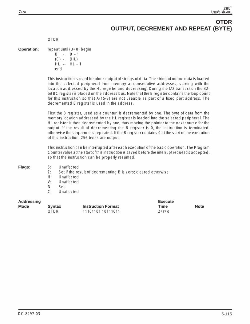
5-115
Z380™
USER'S MANUALZILOG
DC-8297-03
OTDROUTPUT, DECREMENT AND REPEAT (BYTE)
OTDR
Operation: repeat until (B=0) beginB ← B – 1(C) ← (HL)HL ← HL – 1end
This instruction is used for block output of strings of data. The string of output data is loadedinto the selected peripheral from memory at consecutive addresses, starting with thelocation addressed by the HL register and decreasing. During the I/O transaction the 32-bit BC register is placed on the address bus. Note that the B register contains the loop countfor this instruction so that A(15-8) are not useable as part of a fixed port address. Thedecremented B register is used in the address.
First the B register, used as a counter, is decremented by one. The byte of data from thememory location addressed by the HL register is loaded into the selected peripheral. TheHL register is then decremented by one, thus moving the pointer to the next source for theoutput. If the result of decrementing the B register is 0, the instruction is terminated,otherwise the sequence is repeated. If the B register contains 0 at the start of the executionof this instruction, 256 bytes are output.
This instruction can be interrupted after each execution of the basic operation. The ProgramCounter value at the start of this instruction is saved before the interrupt request is accepted,so that the instruction can be properly resumed.
Flags: S: UnaffectedZ: Set if the result of decrementing B is zero; cleared otherwiseH: UnaffectedV: UnaffectedN: SetC: Unaffected
Addressing ExecuteMode Syntax Instruction Format Time Note
OTDR 11101101 10111011 2+r+o

5-116
Z380™
USER'S MANUAL
DC-8297-03
ZILOG
OTDRWOUTPUT, DECREMENT AND REPEAT (WORD)
OTDRW
Operation: repeat until (BC=0) beginBC(15-0) ← BC(15-0) – 1(DE) ← (HL)HL ← HL – 2end
This instruction is used for block output of strings of data. The string of output data is loadedinto the selected peripheral from memory at consecutive addresses, starting with thelocation addressed by the HL register and decreasing. During the I/O transaction the 32-bit DE register is placed on the address bus.
First the BC register, used as a counter, is decremented by one. The word of data from thememory location addressed by the HL register is loaded into the selected peripheral. TheHL register is then decremented by two, thus moving the pointer to the next source for theoutput. If the result of decrementing the BC register is 0, the instruction is terminated,otherwise the sequence is repeated. If the BC register contains 0 at the start of the executionof this instruction, 65536 bytes are output.
This instruction can be interrupted after each execution of the basic operation. The ProgramCounter value at the start of this instruction is saved before the interrupt request is accepted,so that the instruction can be properly resumed.
Flags: S: UnaffectedZ: Set if the result of decrementing B is zero; cleared otherwiseH: UnaffectedV: UnaffectedN: SetC: Unaffected
Addressing ExecuteMode Syntax Instruction Format Time Note
OTDRW 11101101 11111011 2+r+o

5-117
Z380™
USER'S MANUALZILOG
DC-8297-03
OTIMOUTPUT INCREMENT MEMORY
OTIM
Operation: (C) ← (HL)C ← C + 1B ← B – 1HL ← HL + 1
This instruction is used for block output of strings of data to on-chip peripherals. No externalI/O transaction will be generated as a result of this instruction, although the I/O address willappear on the address bus and the write data will appear on the data bus while this internalwrite is occurring. The peripheral address is placed on the low byte of the address bus andzeros are placed on all other address lines. The byte of data from the memory locationaddressed by the HL register is loaded to the on-chip I/O port addressed by the C register.The C register, holding the port address, is incremented by one to select the next output port.The B register, used as a counter, is then decremented by one. The HL register is thenincremented by one, thus moving the pointer to the next source for the output.
Flags: S: Set if the result of decrementing B is negative; cleared otherwiseZ: Set if the result of decrementing B is zero; cleared otherwiseH: Set if there is a borrow from bit 4 during the decrement of the B register; cleared
otherwiseP: Set if the result of the decrement of the B register is even; cleared otherwiseN: Set if the most significant bit of the byte transferred was a 1; cleared otherwiseC: Set if there is a borrow from the most significant bit during the decrement of the B
register; cleared otherwise
Addressing ExecuteMode Syntax Instruction Format Time Note
OTIM 11101101 10000011 2+r+o

5-118
Z380™
USER'S MANUAL
DC-8297-03
ZILOG
OTIMROUTPUT, INCREMENT MEMORY REPEAT
OTIMR
Operation: repeat until (B=0) begin(C) ← (HL)C ← C + 1B ← B – 1HL ← HL + 1end
This instruction is used for block output of strings of data to on-chip peripherals. No externalI/O transaction will be generated as a result of this instruction, although the I/O address willappear on the address bus and the write data will appear on the data bus while this internalwrite is occurring. The peripheral address is placed on the low byte of the address bus andzeros are placed on all other address lines. The byte of data from the memory locationaddressed by the HL register is loaded to the on-chip I/O port addressed by the C register.The C register, holding the port address, is incremented by one to select the next output port.The B register, used as a counter, is then decremented by one. The HL register is thenincremented by one, thus moving the pointer to the next source for the output. If the resultof decrementing the B register is 0, the instruction is terminated, otherwise the outputsequence is repeated. Note that if the B register contains 0 at the start of the execution ofthis instruction, 256 bytes are output.
This instruction can be interrupted after each execution of the basic operation. The ProgramCounter value at the start of this instruction is saved before the interrupt request is accepted,so that the instruction can be properly resumed.
Flags: S: ClearedZ: SetH: ClearedP: SetN: Set if the most significant bit of the byte transferred was a 1; cleared otherwsieC: Cleared
Addressing ExecuteMode Syntax Instruction Format Time Note
OTIMR 11101101 10010011 2+r+o

5-119
Z380™
USER'S MANUALZILOG
DC-8297-03
OTIROUTPUT, INCREMENT AND REPEAT (BYTE)
OTIR
Operation: repeat until (B=0) beginB ← B – 1(C) ← (HL)HL ← HL + 1end
This instruction is used for block output of strings of data. The string of output data is loadedinto the selected peripheral from memory at consecutive addresses, starting with thelocation addressed by the HL register and increasing. During the I/O transaction the 32-bitBC register is placed on the address bus. Note that the B register contains the loop countfor this instruction so that A(15-8) are not useable as part of a fixed port address. Thedecremented B register is used in the address.
First the B register, used as a counter, is decremented by one. The byte of data from thememory location addressed by the HL register is loaded into the selected peripheral. TheHL register is then incremented by one, thus moving the pointer to the next source for theoutput. If the result of decrementing the B register is 0, the instruction is terminated,otherwise the sequence is repeated. If the B register contains 0 at the start of the executionof this instruction, 256 bytes are output.
This instruction can be interrupted after each execution of the basic operation. The ProgramCounter value at the start of this instruction is saved before the interrupt request is accepted,so that the instruction can be properly resumed.
Flags: S: UnaffectedZ: Set if the result of decrementing B is zero; cleared otherwiseH: UnaffectedV: UnaffectedN: SetC: Unaffected
Addressing ExecuteMode Syntax Instruction Format Time Note
OTIR 11101101 10110011 2+r+o

5-120
Z380™
USER'S MANUAL
DC-8297-03
ZILOG
OTIRWOUTPUT, INCREMENT AND REPEAT (WORD)
OTIRW
Operation: repeat until (BC=0) beginBC(15-0) ← BC(15-0) – 1(DE) ← (HL)HL ← HL + 2end
This instruction is used for block output of strings of data. The string of output data is loadedinto the selected peripheral from memory at consecutive addresses, starting with thelocation addressed by the HL register and increasing. During the I/O transaction the 32-bitDE register is placed on the address bus.
First the BC register, used as a counter, is decremented by one. The word of data from thememory location addressed by the HL register is loaded into the selected peripheral. TheHL register is then incremented by two, thus moving the pointer to the next source for theoutput. If the result of decrementing the BC register is 0, the instruction is terminated,otherwise the sequence is repeated. If the BC register contains 0 at the start of the executionof this instruction, 65536 bytes are output.
This instruction can be interrupted after each execution of the basic operation. The ProgramCounter value at the start of this instruction is saved before the interrupt request is accepted,so that the instruction can be properly resumed.
Flags: S: UnaffectedZ: Set if the result of decrementing B is zero; cleared otherwiseH: UnaffectedV: UnaffectedN: SetC: Unaffected
Addressing ExecuteMode Syntax Instruction Format Time Note
OTIRW 11101101 11110011 2+r+o

5-121
Z380™
USER'S MANUALZILOG
DC-8297-03
OUTOUTPUT (BYTE)
OUT (C),src src = R, IM
Operation: (C) ← src
The byte of data from the source is loaded into the selected peripheral. During the I/Otransaction, the contents of the 32-bit BC register are placed on the address bus.
Flags: S: UnaffectedZ: UnaffectedH: UnaffectedV: UnaffectedN: UnaffectedC: Unaffected
Addressing ExecuteMode Syntax Instruction Format Time NoteR: OUT (C),R 11101101 01 -r- 001 3+oIM: OUT (C),n 11101101 01110001 —n— 3+o
Field Encodings: r: per convention

5-122
Z380™
USER'S MANUAL
DC-8297-03
ZILOG
OUTWOUTPUT (WORD)
OUTW (C),src src = R, IM
Operation: (C) ← src(15-0)
The word of data from the source is loaded into the selected peripheral. During the I/Otransaction, the contents of the 32-bit BC register are placed on the address bus.
Flags: S: UnaffectedZ: UnaffectedH: UnaffectedV: UnaffectedN: UnaffectedC: Unaffected
Addressing ExecuteMode Syntax Instruction Format Time NoteR: OUTW (C),R 11011101 01rrr 001 2+oIM: OUTW (C),nn 11111101 01111001 -n(low)- -n(high) 2+o
Field Encodings: rrr: 000 for BC, 010 for DE, 111 for HL

5-123
Z380™
USER'S MANUALZILOG
DC-8297-03
OUTOUTPUT ACCUMULATOR
OUT (n),A
Operation: (n) ← A
The byte of data from the accumulator is loaded into the selected peripheral. During theI/O transaction, the 8-bit peripheral address from the instruction is placed on the low byteof the address bus, the contents of the accumulator are placed on address lines A(15-8),and the high-order address lines are all zeros.
Flags: S: UnaffectedZ: UnaffectedH: UnaffectedV: UnaffectedN: UnaffectedC: Unaffected
Addressing ExecuteMode Syntax Instruction Format Time Note
OUT (n),A 11010011 ——n— 3+o

5-124
Z380™
USER'S MANUAL
DC-8297-03
ZILOG
OUT0OUTPUT (TO PAGE 0)
OUT0 (n),src src = R
Operation: (n) ← src
The byte of data from the source register is loaded into the selected on-chip peripheral. Noexternal I/O transaction will be generated as a result of this instruction, although the I/Oaddress will appear on the address bus and the write data will appear on the data bus whilethis internal write is occurring. The peripheral address is placed on the low byte of theaddress bus and zeros are placed on all other address lines.
Flags: S: UnaffectedZ: UnaffectedH: UnaffectedV: UnaffectedN: UnaffectedC: Unaffected
Addressing ExecuteMode Syntax Instruction Format Time NoteR: OUT0 (n),R 11101101 00-r-001 ——n— 3+o
Field Encodings: r: per convention

5-125
Z380™
USER'S MANUALZILOG
DC-8297-03
OUTAOUTPUT DIRECT TO PORT ADDRESS (BYTE)
OUT (nn),A
Operation: (nn) ← A
The byte of data from the accumulator is loaded into the selected peripheral. During theI/O transaction, the peripheral address from the instruction is placed on the address bus.Any bytes of address not specified in the instruction are driven on the address lines are allzeros.
Flags: S: UnaffectedZ: UnaffectedH: UnaffectedV: UnaffectedN: UnaffectedC: Unaffected
Addressing ExecuteMode Syntax Instruction Format Time Note
OUTA (nn),A 11101101 11010011 -n(low)- -n(high) 2+o I

5-126
Z380™
USER'S MANUAL
DC-8297-03
ZILOG
OUTAWOUTPUT DIRECT TO PORT ADDRESS (WORD)
OUT (nn),HL
Operation: (nn)← HL(15-0)
The word of data from the HL register is loaded into the selected peripheral. During theI/O transaction, the peripheral address from the instruction is placed on the address bus.Any bytes of address not specified in the instruction are driven on the address lines are allzeros.
Flags: S: UnaffectedZ: UnaffectedH: UnaffectedV: UnaffectedN: UnaffectedC: Unaffected
Addressing ExecuteMode Syntax Instruction Format Time Note
OUTAW (nn),HL 11111101 11010011 -n(low)- -n(high) 2+o I
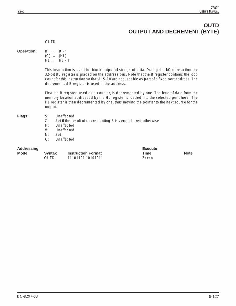
5-127
Z380™
USER'S MANUALZILOG
DC-8297-03
OUTDOUTPUT AND DECREMENT (BYTE)
OUTD
Operation: B ← B - 1(C) ← (HL)HL ← HL - 1
This instruction is used for block output of strings of data. During the I/O transaction the32-bit BC register is placed on the address bus. Note that the B register contains the loopcount for this instruction so that A15-A8 are not useable as part of a fixed port address. Thedecremented B register is used in the address.
First the B register, used as a counter, is decremented by one. The byte of data from thememory location addressed by the HL register is loaded into the selected peripheral. TheHL register is then decremented by one, thus moving the pointer to the next source for theoutput.
Flags: S: UnaffectedZ: Set if the result of decrementing B is zero; cleared otherwiseH: UnaffectedV: UnaffectedN: SetC: Unaffected
Addressing ExecuteMode Syntax Instruction Format Time Note
OUTD 11101101 10101011 2+r+o

5-128
Z380™
USER'S MANUAL
DC-8297-03
ZILOG
OUTDWOUTPUT AND DECREMENT (WORD)
OUTDW
Operation: BC(15-0) ← BC(15-0) - 1(DE) ← (HL)HL ← HL - 2
This instruction is used for block output of strings of data. During the I/O transaction the 32-bit DE register is placed on the address bus.
First the BC register, used as a counter, is decremented by one. The word of data from thememory location addressed by the HL register is loaded into the selected peripheral. TheHL register is then decremented by two, thus moving the pointer to the next source for theoutput.
Flags: S: UnaffectedZ: Set if the result of decrementing BC is zero; cleared otherwiseH: UnaffectedV: UnaffectedN: SetC: Unaffected
Addressing ExecuteMode Syntax Instruction Format Time Note
OUTDW 11101101 11101011 2+r+o

5-129
Z380™
USER'S MANUALZILOG
DC-8297-03
OUTIOUTPUT AND INCREMENT (BYTE)
OUTI
Operation: B ← B - 1(C) ← (HL)HL ← HL + 1
This instruction is used for block output of strings of data. During the I/O transaction the 32-bit BC register is placed on the address bus. Note that the B register contains the loop countfor this instruction so that A15-A8 are not useable as part of a fixed port address. Thedecremented B register is used in the address.
First the B register, used as a counter, is decremented by one. The byte of data from thememory location addressed by the HL register is loaded into the selected peripheral. TheHL register is then incremented by one, thus moving the pointer to the next source for theoutput.
Flags: S: UnaffectedZ: Set if the result of decrementing B is zero; cleared otherwiseH: UnaffectedV: UnaffectedN: SetC: Unaffected
Addressing ExecuteMode Syntax Instruction Format Time Note
OUTI 11101101 10100011 2+r+o

5-130
Z380™
USER'S MANUAL
DC-8297-03
ZILOG
OUTIWOUTPUT AND INCREMENT (WORD)
OUTIW
Operation: BC(15-0) ← BC(15-0) –1(DE) ← (HL)HL ← HL + 2
This instruction is used for block output of strings of data. During the I/O transaction the 32-bit DE register is placed on the address bus.
First the BC register, used as a counter, is decremented by one. The word of data from thememory location addressed by the HL register is loaded into the selected peripheral. TheHL register is then incremented by two, thus moving the pointer to the next source for theoutput.
Flags: S: UnaffectedZ: Set if the result of decrementing BC is zero; cleared otherwiseH: UnaffectedV: UnaffectedN: SetC: Unaffected
Addressing ExecuteMode Syntax Instruction Format Time Note
OUTIW 11101101 11100011 2+r+o

5-131
Z380™
USER'S MANUALZILOG
DC-8297-03
POPPOP ACCUMULATOR
POP dst dst = AF
Operation: F ← (SP)A ← (SP+1)SP ← SP + 2if (LW) then begin
SP ← SP + 2end
The contents of the memory location addressed by the Stack Pointer (SP) are loaded intothe destination in ascending byte order from ascending address memory locations. For thisinstruction, the Flag register is the least significant byte, followed by the Accumulator. TheSP is then incremented by two (by four in the Long Word mode). Note that in the Long Wordmode only one word is read from memory, although the SP is in fact incremented by four.
Flags: S: Loaded from (SP)Z: Loaded from (SP)H: Loaded from (SP)V: Loaded from (SP)N: Loaded from (SP)C: Loaded from (SP)
Addressing ExecuteMode Syntax Instruction Format Time Note
POP AF 11110001 2+r L

5-132
Z380™
USER'S MANUAL
DC-8297-03
ZILOG
POPPOP CONTROL REGISTER
POP dst dst = SR
Operation: if (LW) then begindst(6-0) ← (SP)dst(15-8) ← (SP+1)dst(23-16) ← (SP+2)dst(31-24) ← (SP+3)SP ← SP + 4end
else begindst(6-0) ← (SP)dst(15-8) ← (SP+1)dst(23-16) ← (SP+1)dst(31-24) ← (SP+1)SP ← SP + 2end
The contents of the memory location addressed by the Stack Pointer (SP) are loaded intothe destination in ascending byte order from ascending address memory locations. The SPis then incremented by two (by four in the Long Word mode). Note that when not in the LongWord mode the most significant byte read from memory is also written to the two mostsignificant bytes of the SR. Also note that the XM bit is unaffected by this instruction.
Flags: S: UnaffectedZ: UnaffectedH: UnaffectedV: UnaffectedN: UnaffectedC: Unaffected
Addressing ExecuteMode Syntax Instruction Format Time Note
POP SR 11101101 11000001 3+r L

5-133
Z380™
USER'S MANUALZILOG
DC-8297-03
POPPOP REGISTER
POP dst dst = R, RX
Operation: if (LW) then begindst(7-0 ) ← (SP)dst(15-8) ← (SP+1)dst(23-16) ← (SP+2)dst(31-24) ← (SP+3)SP ← SP + 4end
else begindst(7-0) ← (SP)dst(15-8) ← (SP+1)SP ← SP + 2end
The contents of the memory location addressed by the Stack Pointer (SP) are loaded intothe destination in ascending byte order from ascending address memory locations. The SPis then incremented by two (by four in the Long Word mode).
Flags: S: UnaffectedZ: UnaffectedH: UnaffectedV: UnaffectedN: UnaffectedC: Unaffected
Addressing ExecuteMode Syntax Instruction Format Time NoteR: POP R 11rr 0001 1+r LRX: POP RX 11y11101 11100001 1+r L
Field Encodings: rr: 00 for BC, 01 for DE, 10 for HLy: 0 for IX, 1 for IY

5-134
Z380™
USER'S MANUAL
DC-8297-03
ZILOG
PUSHPUSH ACCUMULATOR
PUSH src src = AF
Operation: if (LW) then beginSP ← SP - 4(SP) ← F(SP+1) ← A(SP+2) ← 00h(SP+3) ← 00hend
else beginSP ← SP - 2(SP) ← F(SP+1) ← Aend
The Stack Pointer (SP) is decremented by two (by four in Long Word mode) and the sourceis loaded into the memory locations addressed by the SP in ascending byte order inascending address memory locations. For this instruction, the Flag register is the leastsignificant byte, followed by the Accumulator. The other two bytes written in the Long Wordmode are all zeros. The Flag register and Accumulator are unaffected.
Flags: S: UnaffectedZ: UnaffectedH: UnaffectedV: UnaffectedN: UnaffectedC: Unaffected
Addressing ExecuteMode Syntax Instruction Format Time Note
PUSH AF 11110101 3+w L

5-135
Z380™
USER'S MANUALZILOG
DC-8297-03
PUSHPUSH CONTROL REGISTER
PUSH src src = SR
Operation: if (LW) then beginSP ← SP - 4(SP) ← src(7-0)(SP+1) ← src(15-8)(SP+2) ← src(23-16)(SP+3) ← src(31-24)end
else beginSP ← SP - 2(SP) ← src(7-0)(SP+1) ← src(15-8)end
The Stack Pointer (SP) is decremented by two (by four in Long Word mode) and the sourceis loaded into the memory locations addressed by the SP in ascending byte order inascending address memory locations. The contents of the source are unaffected.
Flags: S: UnaffectedZ: UnaffectedH: UnaffectedV: UnaffectedN: UnaffectedC: Unaffected
Addressing ExecuteMode Syntax Instruction Format Time Note
PUSH SR 11101101 11000101 3+w L

5-136
Z380™
USER'S MANUAL
DC-8297-03
ZILOG
PUSHPUSH IMMEDIATE
PUSH src src = IM
Operation: if (LW) then beginSP ← SP - 4(SP) ← src(7-0)(SP+1) ← src(15-8)(SP+2) ← src(23-16)(SP+3) ← src(31-24)end
else beginSP ← SP - 2(SP) ← src(7-0)(SP+1) ← src(15-8)end
The Stack Pointer (SP) is decremented by two (by four in Long Word mode) and the sourceis loaded into the memory locations addressed by the SP in ascending byte order inascending address memory locations.
Flags: S: UnaffectedZ: UnaffectedH: UnaffectedV: UnaffectedN: UnaffectedC: Unaffected
Addressing ExecuteMode Syntax Instruction Format Time NoteIM: PUSH nn 11111101 11110101 -n(low)- -n(high) 3+w I, L

5-137
Z380™
USER'S MANUALZILOG
DC-8297-03
PUSHPUSH REGISTER
PUSH src src = R, RX
Operation: if (LW) then beginSP ← SP - 4(SP) ← src(7-0)(SP+1) ← src(15-8)(SP+2) ← src(23-16)(SP+3) ← src(31-24)end
else beginSP ← SP - 2(SP) ← src(7-0)(SP+1) ← src(15-8)end
The Stack Pointer (SP) is decremented by two (by four in Long Word mode) and the sourceis loaded into the memory locations addressed by the SP in ascending byte order inascending address memory locations. The contents of the source are unaffected.
Flags: S: UnaffectedZ: UnaffectedH: UnaffectedV: UnaffectedN: UnaffectedC: Unaffected
Addressing ExecuteMode Syntax Instruction Format Time NoteR: PUSH R 11rr0101 3+w LRX: PUSH RX 11y11101 11100101 3+w L
Field Encodings: rr: 00 for BC, 01 for DE, 10 for HLy: 0 for IX, 1 for IY

5-138
Z380™
USER'S MANUAL
DC-8297-03
ZILOG
RESRESET BIT
RES b, dst dst = R, IR, X
Operation: dst(b) ← 0
The specified bit b within the destination operand is cleared to 0. The other bits in thedestination are unaffected. The bit to be reset is specified by a 3-bit field in the instruction;this field contains the binary encoding for the bit number to be cleared. The bit number bmust be between 0 and 7.
Flags: S: UnaffectedZ: UnaffectedH: UnaffectedV: UnaffectedN: UnaffectedC: Unaffected
Addressing ExecuteMode Syntax Instruction Format Time NoteR: RES b,R 11001011 10bbb -r- 2IR: RES b,(HL) 11001011 10bbb110 2+rX: RES b,(XY+d) 11y11101 11001011 ——d— 10bbb110 4+r I
Field Encodings: r: per conventiony: 0 for IX, 1 for IY

5-139
Z380™
USER'S MANUALZILOG
DC-8297-03
RESCRESET CONTROL BIT
RESC mode mode = LCK, LW
Operation: if (mode = LCK) then beginSR(1) ← 0end
else beginSR(6) ← 0end
When reseting Lock mode (LCK), the LCK bit (bit 1) in the Select Register (SR) is set to 0,enabling external bus requests. Note that these requests cannot be granted until after theinstruction has been executed, and that one or more of the succeeding instructions may alsohave been fetched for decoding before this instruction has been executed.
When reseting Long Word mode (LW), the LW bit (bit 6) in the SR is set to 0, selecting 16-bit words. When using 16-bit words, all word load operations transfer 16 bits.
Flags: S: UnaffectedZ: UnaffectedH: UnaffectedV: UnaffectedN: UnaffectedC: Unaffected
Addressing ExecuteMode Syntax Instruction Format Time Note
RESC mode 11mm1101 11111111 4
Field Encodings: mm: 01 for LW, 10 for LCK

5-140
Z380™
USER'S MANUAL
DC-8297-03
ZILOG
RETRETURN
RET [cc]
Operation: if (cc is TRUE) then beginif (XM) then begin
PC(7-0) ← (SP)PC(15-8) ← (SP+1)PC(23-16) ← (SP+2)PC(31-24) ← (SP+3)SP ← SP + 4end
else beginPC(7-0) ← (SP)PC(15-8) ← (SP+1)SP ← SP + 2end
end
This instruction is used to return to a previously executing procedure at the end of aprocedure entered by a Call instruction. For a conditional return, one of the Zero, Carry, Sign,or Parity/Overflow flags is checked to see if its setting matches the condition code “cc”encoded in the instruction; if the condition is not satisfied, the instruction following the Returninstruction is executed, otherwise a value is popped from the stack and loaded into theProgram Counter (PC), thereby specifying the location of the next instruction to be executed.For an unconditional return, the return is always taken and a condition code is not specified.
This instruction is also used to return to a previously executing procedure at the end of aprocedure entered by an interrupt in the assigned vectors mode, if Z80 family peripheralsare used external to the Z380 MPU.
Flags: S: UnaffectedZ: UnaffectedH: UnaffectedV: UnaffectedN: UnaffectedC: Unaffected
Addressing ExecuteMode Syntax Instruction Format Time Note
RET CC 11-cc000 note XRET 11001001 2+r X
Field Encodings: cc: 000 for NZ, 001 for Z, 010 for NC, 011 for C,100 for PO/NV, 101 for PE/V, 110 for P/NS, 111 for M/S
Note: 2 if CC is false, 2+r if CC is true

5-141
Z380™
USER'S MANUALZILOG
DC-8297-03
RETBRETURN FROM BREAKPOINT
Operation: PC (31-0) ← SPC (31-0)
This instruction is used to return to a previously executing procedure at the end of abreakpoint. The contents of the Shadow Program Counter (SPC), which holds the addressof the next instruction of the previously executing procedure, are loaded into the ProgramCounter (PC).
Note that maskable interrupts (if IEF1 is set) and non-maskable interrupt are enabled afterthe instruction following RETB is executed.
Flags: S: UnaffectedZ: UnaffectedH: UnaffectedV: UnaffectedN: UnaffectedC: Unaffected
Addressing ExecuteMode Syntax Instruction Format Time Note
RETB 11101101 01010101 2

5-142
Z380™
USER'S MANUAL
DC-8297-03
ZILOG
RETIRETURN FROM INTERRUPT
RETI
Operation: if (XM) then beginPC(7-0) ← (SP)PC(15-8) ← (SP+1)PC(23-16) ← (SP+2)PC(31-24) ← (SP+3)SP ← SP + 4end
else beginPC(7-0) ← (SP)PC(15-8) ← (SP+1)SP ← SP + 2end
This instruction is used to return to a previously executing procedure at the end of aprocedure entered by an interrupt. The contents of the location addressed by the StackPointer (SP) are popped into the Program Counter (PC), thereby specifying the location ofthe next instruction to be executed. A special sequence of bus transactions is performedwhen this instruction is executed in order to control Z80 family peripherals; see thedescription of the external interface for more details.
Flags: S: UnaffectedZ: UnaffectedH: UnaffectedV: UnaffectedN: UnaffectedC: Unaffected
Addressing ExecuteMode Syntax Instruction Format Time Note
RETI 11101101 01001101 2+r X

5-143
Z380™
USER'S MANUALZILOG
DC-8297-03
RETNRETURN FROM NONMASKABLE INTERRUPT
RETN
Operation: if (XM) then beginPC(7-0) ← (SP)PC(15-8) ← (SP+1)PC(23-16) ← (SP+2)PC(31-24) ← (SP+3)SP ← SP + 4end
else beginPC(7-0) ← (SP)PC(15-8) ← (SP+1)SP ← SP + 2end
IEF1 ← IEF2
This instruction is used to return to a previously executing procedure at the end of aprocedure entered by a nonmaskable interrupt. The contents of the location addressed bythe Stack Pointer (SP) are popped into the Program Counter (PC), thereby specifying thelocation of the next instruction to be executed. The previous setting of the interrupt enablebit is restored by execution of this instruction.
Flags: S: UnaffectedZ: UnaffectedH: UnaffectedV: UnaffectedN: UnaffectedC: Unaffected
Addressing ExecuteMode Syntax Instruction Format Time Note
RETN 11101101 01000101 2+r X

5-144
Z380™
USER'S MANUAL
DC-8297-03
ZILOG
RLROTATE LEFT (BYTE)
RL dst dst = R, IR, X
Operation: tmp ← dstdst(0) ← CC ← dst(7)dst(n+1) ← tmp(n) for n = 0 to 6
The contents of the destination operand are concatenated with the Carry flag and togetherthey are rotated left one bit position. Bit 7 of the destination operand is moved to the Carryflag and the Carry flag is moved to bit 0 of the destination.
Flags: S: Set if the most significant bit of the result is set; cleared otherwiseZ: Set if the result is zero; cleared otherwiseH: ClearedP: Set if parity of the result is even; cleared otherwiseN: ClearedC: Set if the bit rotated from bit 7 was a 1; cleared otherwise
Addressing ExecuteMode Syntax Instruction Format Time NoteR: RL R 11001011 00010-r- 2IR: RL (HL) 11001011 00010110 2+rX: RL (XY+d) 11y11101 11001011 ——d— 00010110 4+r I
Field Encodings: r: per conventiony: 0 for IX, 1 for IY

5-145
Z380™
USER'S MANUALZILOG
DC-8297-03
RLWROTATE LEFT (WORD)
RLW dst dst = R, RX, IR, X
Operation: tmp ← dstdst(0) ← CC ← dst(15)dst(n+1) ← tmp(n) for n = 0 to 14
The contents of the destination operand are concatenated with the Carry flag and togetherthey are rotated left one bit position. The most significant bit of the destination operand ismoved to the Carry flag and the Carry flag is moved to bit 0 of the destination.
Flags: S: Set if the most significant bit of the result is set; cleared otherwiseZ: Set if the result is zero; cleared otherwiseH: ClearedP: Set if parity of the result is even; cleared otherwiseN: ClearedC: Set if the bit rotated from the most significant bit was a 1; cleared otherwise
Addressing ExecuteMode Syntax Instruction Format Time NoteR: RLW R 11101101 11001011 000100rr 2RX: RLW RX 11101101 11001011 0001010y 2IR: RLW (HL) 11101101 11001011 00010010 2+rX: RLW (XY+d) 11y11101 11001011 ——d— 00010010 4+r I
Field Encodings: rr: 00 for BC, 01 for DE, 11 for HLy: 0 for IX, 1 for IY

5-146
Z380™
USER'S MANUAL
DC-8297-03
ZILOG
RLAROTATE LEFT (ACCUMULATOR)
RLA
Operation: tmp ← AA(0) ← CC ← A(7)A(n+1) ← tmp(n) for n = 0 to 6
The contents of the accumulator are concatenated with the Carry flag and together they arerotated left one bit position. Bit 7 of the accumulator is moved to the Carry flag and the Carryflag is moved to bit 0 of the accumulator.
Flags: S: UnaffectedZ: UnaffectedH: ClearedP: UnaffectedN: ClearedC: Set if the bit rotated from bit 7 was a 1; cleared otherwise
Addressing ExecuteMode Syntax Instruction Format Time Note
RLA 00010111 2

5-147
Z380™
USER'S MANUALZILOG
DC-8297-03
RLCROTATE LEFT CIRCULAR (BYTE)
RLC dst dst = R, IR, X
Operation: tmp ← dstC ← dst(7)dst(0) ← tmp(7)dst(n+1) ← tmp(n) for n = 0 to 6
The contents of the destination operand are rotated left one bit position. Bit 7 of thedestination operand is moved to the bit 0 position and also replaces the Carry flag.
Flags: S: Set if the most significant bit of the result is set; cleared otherwiseZ: Set if the result is zero; cleared otherwiseH: ClearedP: Set if parity of the result is even; cleared otherwiseN: ClearedC: Set if the bit rotated from bit 7 was a 1; cleared otherwise
Addressing ExecuteMode Syntax Instruction Format Time NoteR: RLC R 11001011 00000-r- 2IR: RLC (HL) 11001011 00000110 2+rX: RLC (XY+d) 11y11101 11001011 ——d— 00000110 4+r I
Field Encodings: r: per conventiony: 0 for IX, 1 for IY

5-148
Z380™
USER'S MANUAL
DC-8297-03
ZILOG
RLCWROTATE LEFT CIRCULAR (WORD)
RLCW dst dst = R, RX, IR, X
Operation: tmp ← dstC ← dst(15)dst(0) ← tmp(15)dst(n+1) ← tmp(n) for n = 0 to 14
The contents of the destination operand are rotated left one bit position. The most significantbit of the destination operand is moved to the bit 0 position and also replaces the Carry flag.
Flags: S: Set if the most significant bit of the result is set; cleared otherwiseZ: Set if the result is zero; cleared otherwiseH: ClearedP: Set if parity of the result is even; cleared otherwiseN: ClearedC: Set if the bit rotated from the most significant bit was a 1; cleared otherwise
Addressing ExecuteMode Syntax Instruction Format Time NoteR: RLCW R 11101101 11001011 000000rr 2RX: RLCW RX 11101101 11001011 0000010y 2IR: RLCW (HL) 11101101 11001011 00000010 2+rX: RLCW (XY+d) 11y11101 11001011 ——d— 00000010 4+r I
Field Encodings: rr: 00 for BC, 01 for DE, 11 for HLy: 0 for IX, 1 for IY

5-149
Z380™
USER'S MANUALZILOG
DC-8297-03
RLCAROTATE LEFT CIRCULAR (ACCUMULATOR)
RLCA
Operation: tmp ← AC ← A(7)A(0) ← tmp(7)A(n+1) ← tmp(n) for n = 0 to 6
The contents of the accumulator are rotated left one bit position. Bit 7 of the accumulator ismoved to the bit 0 position and also replaces the Carry flag.
Flags: S: UnaffectedZ: UnaffectedH: ClearedP: UnaffectedN: ClearedC: Set if the bit rotated from bit 7 was a 1; cleared otherwise
Addressing ExecuteMode Syntax Instruction Format Time Note
RLCA 00000111 2

5-150
Z380™
USER'S MANUAL
DC-8297-03
ZILOG
RLDROTATE LEFT DIGIT
RLD
Operation: tmp(3-0) ← A(3-0)A(3-0) ← dst(7-4)dst(7-4) ← dst(3-0)dst(3-0) ← tmp(3-0)
The low digit of the accumulator is logically concatenated to the destination byte whosememory address is in the HL register. The resulting three-digit quantity is rotated to the leftby one BCD digit (four bits). The lower digit of the source is moved to the upper digit of thesource; the upper digit of the source is moved to the lower digit of the accumulator, and thelower digit of the accumulator is moved to the lower digit of the source. The upper digit ofthe accumulator is unaffected. In multiple-digit BCD arithmetic, this instruction can be usedto shift to the left a string of BCD digits, thus multiplying it by a power of ten. The accumulatorserves to transfer digits between successive bytes of the string. This is analogous to the useof the Carry flag in multiple-precision shifting using the RL instruction.
Flags: S: Set if the accumulator is negative after the operation; cleared otherwiseZ: Set if the accumulator is zero after the operation; cleared otherwiseH: ClearedP: Set if the parity of the accumulator is even after the operation; cleared otherwiseN: ClearedC: Unaffected
Addressing ExecuteMode Syntax Instruction Format Time Note
RLD 11101101 01101111 3+r

5-151
Z380™
USER'S MANUALZILOG
DC-8297-03
RRROTATE RIGHT (BYTE)
RR dst dst = R, IR, X
Operation: tmp ← dstdst(7) ← CC ← dst(0)dst(n) ← tmp(n+1) for n = 0 to 6
The contents of the destination operand are concatenated with the Carry flag and togetherthey are rotated right one bit position. Bit 0 of the destination operand is moved to the Carryflag and the Carry flag is moved to bit 7 of the destination.
Flags: S: Set if the most significant bit of the result is set; cleared otherwiseZ: Set if the result is zero; cleared otherwiseH: ClearedP: Set if parity of the result is even; cleared otherwiseN: ClearedC: Set if the bit rotated from bit 0 was a 1; cleared otherwise
Addressing ExecuteMode Syntax Instruction Format Time NoteR: RR R 11001011 00011-r- 2IR: RR (HL) 11001011 00011110 2+rX: RR (XY+d) 11y11101 11001011 ——d— 00011110 4+r I
Field Encodings: r: per conventiony: 0 for IX, 1 for IY

5-152
Z380™
USER'S MANUAL
DC-8297-03
ZILOG
RRWROTATE RIGHT (WORD)
RRW dst dst = R, RX, IR, X
Operation: tmp ← dstC ← dst(0)dst(15) ← Cdst(n) ← tmp(n+1) for n = 0 to 14
The contents of the destination operand are concatenated with the Carry flag and togetherthey are rotated right one bit position. Bit 0 of the destination operand is moved to the Carryflag and the Carry flag is moved to the most significant bit of the destination.
Flags: S: Set if the most significant bit of the result is set; cleared otherwiseZ: Set if the result is zero; cleared otherwiseH: ClearedP: Set if parity of the result is even; cleared otherwiseN: ClearedC: Set if the bit rotated from bit 0 was a 1; cleared otherwise
Addressing ExecuteMode Syntax Instruction Format Time NoteR: RRW R 11101101 11001011 000110rr 2RX: RRW RX 11101101 11001011 0001110y 2IR: RRW (HL) 11101101 11001011 00011010 2+rX: RRW (XY+d) 11y11101 11001011 ——d— 00011010 4+r I
Field Encodings: rr: 00 for BC, 01 for DE, 11 for HLy: 0 for IX, 1 for IY

5-153
Z380™
USER'S MANUALZILOG
DC-8297-03
RRAROTATE RIGHT (ACCUMULATOR)
RRA
Operation: tmp ← AA(7) ← CC ← A(0)A(n) ← tmp(n+1) for n = 0 to 6
The contents of the accumulator are concatenated with the Carry flag and together they arerotated right one bit position. Bit 0 of the accumulator is moved to the Carry flag and the Carryflag is moved to bit 7 of the accumulator.
Flags: S: UnaffectedZ: UnaffectedH: ClearedP: UnaffectedN: ClearedC: Set if the bit rotated from bit 0 was a 1; cleared otherwise
Addressing ExecuteMode Syntax Instruction Format Time Note
RRA 00011111 2

5-154
Z380™
USER'S MANUAL
DC-8297-03
ZILOG
RRCROTATE RIGHT CIRCULAR (BYTE)
RRC dst dst = R, IR, X
Operation: tmp ← dstC ← dst(0)dst(7) ← tmp(0)dst(n) ← tmp(n+1) for n = 0 to 6
The contents of the destination operand are rotated right one bit position. Bit 0 of thedestination operand is moved to the bit 7 position and also replaces the Carry flag.
Flags: S: Set if the most significant bit of the result is set; cleared otherwiseZ: Set if the result is zero; cleared otherwiseH: ClearedP: Set if parity of the result is even; cleared otherwiseN: ClearedC: Set if the bit rotated from bit 0 was a 1; cleared otherwise
Addressing ExecuteMode Syntax Instruction Format Time NoteR: RRC R 11001011 00001-r- 2IR: RRC (HL) 11001011 00001110 2+rX: RRC (XY+d) 11y11101 11001011 ——d— 00001110 4+r I
Field Encodings: r: per conventiony: 0 for IX, 1 for IY

5-155
Z380™
USER'S MANUALZILOG
DC-8297-03
RRCWROTATE RIGHT CIRCULAR (WORD)
RRCW dst dst = R, RX, IR, X
Operation: tmp ← dstC ← dst(0)dst(15) ← tmp(0)dst(n) ← tmp(n+1) for n = 0 to 14
The contents of the destination operand are rotated right one bit position. Bit 0 of thedestination operand is moved to the most significant bit position and also replaces the Carryflag.
Flags: S: Set if the most significant bit of the result is set; cleared otherwiseZ: Set if the result is zero; cleared otherwiseH: ClearedP: Set if parity of the result is even; cleared otherwiseN: ClearedC: Set if the bit rotated from bit 0 was a 1; cleared otherwise
Addressing ExecuteMode Syntax Instruction Format Time NoteR: RRCW R 11101101 11001011 000010rr 2RX: RRCW RX 11101101 11001011 0000110y 2IR: RRCW (HL) 11101101 11001011 00001010 2+rX: RRCW (XY+d) 11y11101 11001011 ——d— 00001010 4+r I
Field Encodings: rr: 00 for BC, 01 for DE, 11 for HLy: 0 for IX, 1 for IY

5-156
Z380™
USER'S MANUAL
DC-8297-03
ZILOG
RRCAROTATE RIGHT CIRCULAR (ACCUMULATOR)
RRCA
Operation: tmp ← AC ← A(0)A(7) ← tmp(0)A(n) ← tmp(n+1) for n = 0 to 6
The contents of the accumulator are rotated right one bit position. Bit 0 of the accumulatoris moved to the bit 7 position and also replaces the Carry flag.
Flags: S: UnaffectedZ: UnaffectedH: ClearedP: UnaffectedN: ClearedC: Set if the bit rotated from bit 0 was a 1; cleared otherwise
Addressing ExecuteMode Syntax Instruction Format Time Note
RRCA 00001111 2
5-157
Z380™
USER'S MANUALZILOG
DC-8297-03
RRDROTATE RIGHT DIGIT
RRD
Operation: tmp(3-0) ← A(3-0)A(3-0) ← dst(3-0)dst(3-0) ← dst(7-4)dst(7-4) ← tmp(3-0)
The low digit of the accumulator is logically concatenated to the destination byte whosememory address is in the HL register. The resulting three-digit quantity is rotated to the rightby one BCD digit (four bits). The upper digit of the source is moved to the lower digit of thesource; the lower digit of the source is moved to the lower digit of the accumulator, and thelower digit of the accumulator is moved to the upper digit of the source. The upper digit ofthe accumulator is unaffected. In multiple-digit BCD arithmetic, this instruction can be usedto shift to the right a string of BCD digits, thus dividing it by a power of ten. The accumulatorserves to transfer digits between successive bytes of the string. This is analogous to the useof the Carry flag in multiple-precision shifting using the RR instruction.
Flags: S: Set if the accumulator is negative after the operation; cleared otherwiseZ: Set if the accumulator is zero after the operation; cleared otherwiseH: ClearedP: Set if the parity of the accumulator is even after the operation; cleared otherwiseN: ClearedC: Unaffected
Addressing ExecuteMode Syntax Instruction Format Time Note
RRD 11101101 01100111 3+r

5-158
Z380™
USER'S MANUAL
DC-8297-03
ZILOG
RSTRESTART
RST address
Operation: if (XM) then beginSP ← SP - 4(SP) ← PC(7-0)(SP+1) ← PC(15-8)(SP+2) ← PC(23-16)(SP+3) ← PC(31-24)end
else beginSP ← SP - 2(SP) ← PC(7-0)(SP+1) ← PC(15-8)end
PC ← address
The current Program Counter (PC) is pushed onto the stack and the PC is loaded with aconstant address encoded in the instruction. Execution then begins at this address. Therestart instruction allows for a call to one of eight fixed locations as shown in the table below.The table also indicates the encoding of the address used in the instruction encoding. (Theaddress is in hexadecimal, the encoding in binary.)
Address t encoding00000000h 00000000008h 00100000010h 01000000018h 01100000020h 10000000028h 10100000030h 11000000038h 111
Flags: S: UnaffectedZ: UnaffectedH: UnaffectedV: UnaffectedN: UnaffectedC: Unaffected
Addressing ExecuteMode Syntax Instruction Format Time Note
RST address 11-t-111 4+w X
Field Encodings: 000 for 00h, 001 for 08h, 010 for 10h, 011 for 18h,100 for 20h, 101 for 28h, 110 for 30h, 111 for 38h

5-159
Z380™
USER'S MANUALZILOG
DC-8297-03
SBCSUBTRACT WITH CARRY (BYTE)
SBC A,src src = R, RX, IM, IR, X
Operation: A ← A - src - C
The source operand together with the Carry flag is subtracted from the accumulator and thedifference is stored in the accumulator. The contents of the source are unaffected. Two'scomplement subtraction is performed.
Flags: S: Set if the result is negative; cleared otherwiseZ: Set if the result is zero; cleared otherwiseH: Set if there is a borrow from bit 4 of the result; cleared otherwiseV: Set if arithmetic overflow occurs, that is, if the operands are of different signs and the
result is of the same sign as the source; cleared otherwiseN: SetC: Set if there is a borrow from the most significant bit of the result; cleared otherwise
Addressing ExecuteMode Syntax Instruction Format Time NoteR: SBC A,R 10011-r- 2RX: SBC A,RX 11y11101 1001110w 2IM: SBC A,n 11011110 ——n— 2IR: SBC A,(HL) 10011110 2+rX: SBC A,(XY+d) 11y11101 10011110 ——d— 4+r I
Field Encodings: r: per conventiony: 0 for IX, 1 for IYw: 0 for high byte, 1 for low byte

5-160
Z380™
USER'S MANUAL
DC-8297-03
ZILOG
SBCSUBTRACT WITH CARRY (WORD)
SBC HL,src dst = HLsrc = BC, DE, HL, SP
Operation: HL(15-0) ← HL(15-0) - src(15-0) - C
The source operand together with the Carry flag is subtracted from the HL register and thedifference is stored in the HL register. The contents of the source are unaffected. Two'scomplement subtraction is performed.
Flags: S: Set if the result is negative; cleared otherwiseZ: Set if the result is zero; cleared otherwiseH: Set if there is a borrow from bit 12 of the result; cleared otherwiseV: Set if arithmetic overflow occurs, that is, if the operands are of different signs and the
result is of the same sign as the the source; cleared otherwiseN: SetC: Set if there is a borrow from the most significant bit of the result; cleared otherwise
Addressing ExecuteMode Syntax Instruction Format Time NoteR: SBC HL,R 11101101 01rr0010 2
Field Encodings: rr: 00 for BC, 01 for DE, 10 for HL, 11 for SP

5-161
Z380™
USER'S MANUALZILOG
DC-8297-03
SBCWSUBTRACT WITH CARRY (WORD)
SBCW [HL,]src src = R, RX, IM, X
Operation: HL(15-0) ← HL(15-0) - src(15-0) - C
The source operand together with the Carry flag is subtracted from the HL register and thedifference is stored in the HL register. The contents of the source are unaffected. Two'scomplement subtraction is performed.
Flags: S: Set if the result is negative; cleared otherwiseZ: Set if the result is zero; cleared otherwiseH: Set if there is a borrow from bit 12 of the result; cleared otherwiseV: Set if arithmetic overflow occurs, that is, if the operands are of different signs and the
result is of the same sign as the source; cleared otherwiseN: SetC: Set if there is a borrow from the most significant bit of the result; cleared otherwise
Addressing ExecuteMode Syntax Instruction Format Time NoteR: SBCW [HL,]R 11101101 100111rr 2RX: SBCW [HL,]RX 11y11101 10011111 2IM: SBCW [HL,]nn 11101101 10011110 -n(low) -n(high)- 2X: SBCW [HL,](XY+d) 11y11101 11011110 ——d— 4+r I
Field Encodings: rr: 00 for BC, 01 for DE, 11 for HLy: 0 for IX, 1 for IY

5-162
Z380™
USER'S MANUAL
DC-8297-03
ZILOG
SCFSET CARRY FLAG
SCF
Operation: C ← 1
The Carry flag is set to 1.
Flags: S: UnaffectedZ: UnaffectedH: ClearedV: UnaffectedN: ClearedC: Set
Addressing ExecuteMode Syntax Instruction Format Time Note
SCF 00110111 2

5-163
Z380™
USER'S MANUALZILOG
DC-8297-03
SETSET BIT
SET b, dst dst = R, IR, X
Operation: dst(b) ← 1
The specified bit b within the destination operand is set to 1. The other bits in the destinationare unaffected. The bit to be set is specified by a 3-bit field in the instruction; this fieldcontains the binary encoding for the bit number to be set. The bit number b must be between0 and 7.
Flags: S: UnaffectedZ: UnaffectedH: UnaffectedV: UnaffectedN: UnaffectedC: Unaffected
Addressing ExecuteMode Syntax Instruction Format Time NoteR: SET b,R 11001011 11bbb -r- 2IR: SET b,(HL) 11001011 11bbb110 2+rX: SET b,(XY+d) 11y11101 11001011 ——d— 11bbb110 4+r I
Field Encodings: r: per conventiony: 0 for IX, 1 for IY

5-164
Z380™
USER'S MANUAL
DC-8297-03
ZILOG
SETCSET CONTROL BIT
SETC mode mode = LCK, LW, XM
Operation: if (mode = LCK) then beginSR(1) ← 1end
else if (mode = LW) then beginSR(6) ← 1end
else beginSR(7) ← 1end
When setting Lock mode (LCK), the LCK bit (bit 1) in the Select Register (SR) is set to 1,disabling external bus requests. Note that bus requests are not disabled until after thisinstruction has been executed, and that one or more of the succeeding instructions may alsohave been fetched for decoding before this instruction has been executed.
When setting Long Word mode (LW), the LW bit (bit 6) in the SR is set to 1, selecting 32-bitwords. When using 32-bit words, all word load instructions transfer 32 bits.
When setting Extended mode (XM), the XM bit (bit 7) in the SR is set to 1, selecting addressesmodulo 4,294,967,296 (32 bits) as opposed to addresses modulo 65536 (16 bits) in Nativemode. In Extended mode CALL and RETurn instructions save and restore 32 bit PC valuesto and from the stack, and the PC pushed to the stack in response to an interrupt is 32 bits.In Extended mode, address manipulation instructions such as INCrement, DECrement,ADD, and Jump Relative (JR) employ 32-bit addresses. Note that it is not possible to exitfrom Extended mode except via reset.
Flags: S: UnaffectedZ: UnaffectedH: UnaffectedV: UnaffectedN: UnaffectedC: Unaffected
Addressing ExecuteMode Syntax Instruction Format Time Note
SETC mode 11mm1101 11110111 4
Field Encodings: mm: 01 for LW, 10 for LCK, 11 for XM

5-165
Z380™
USER'S MANUALZILOG
DC-8297-03
SLASHIFT LEFT ARITHMETIC (BYTE)
SLA dst dst = R, IR, X
Operation: tmp ← dstC ← dst(7)dst(0) ← 0dst(n+1) ← tmp(n) for n = 0 to 6
The contents of the destination operand are shifted left one bit position. Bit 7 of thedestination operand is moved to the Carry flag and zero is shifted into bit 0 of the destination.
Flags: S: Set if the most significant bit of the result is set; cleared otherwiseZ: Set if the result is zero; cleared otherwiseH: ClearedP: Set if parity of the result is even; cleared otherwiseN: ClearedC: Set if the bit shifted from bit 7 was a 1; cleared otherwise
Addressing ExecuteMode Syntax Instruction Format Time NoteR: SLA R 11001011 00100-r- 2IR: SLA (HL) 11001011 00100110 2+rX: SLA (XY+d) 11y11101 11001011 ——d— 00100110 4+r I
Field Encodings: r: per conventiony: 0 for IX, 1 for IY

5-166
Z380™
USER'S MANUAL
DC-8297-03
ZILOG
SLAWSHIFT LEFT ARITHMETIC (WORD)
SLAW dst dst = R, RX, IR, X
Operation: tmp ← dstdst(0) ← 0C ← dst(15)dst(n+1) ← tmp(n) for n = 0 to 14
The contents of the destination operand are shifted left one bit position. The most significantbit of the destination operand is moved to the Carry flag and zero is shifted into bit 0 of thedestination.
Flags: S: Set if the most significant bit of the result is set; cleared otherwiseZ: Set if the result is zero; cleared otherwiseH: ClearedP: Set if parity of the result is even; cleared otherwiseN: ClearedC: Set if the bit shifted from the most significant bit was a 1; cleared otherwise
Addressing ExecuteMode Syntax Instruction Format Time NoteR: SLAW R 11101101 11001011 001000rr 2RX: SLAW RX 11101101 11001011 0010010y 2IR: SLAW (HL) 11101101 11001011 00100010 2+rX: SLAW (XY+d) 11y11101 11001011 ——d— 00100010 4+r I
Field Encodings: rr: 00 for BC, 01 for DE, 11 for HLy: 0 for IX, 1 for IY
5-167
Z380™
USER'S MANUALZILOG
DC-8297-03
SLPSLEEP
SLP
Operation: if (STBY not enabled) thenCPU Halts
elseZ380 enters Standby mode
With Standby mode disabled, this instruction is interpreted and executed as a HALTinstruction.
With Standby mode enabled, executing this instruction causes all device operation to stop,thus minimizing power dissipation. The /STNBY signal is asserted to indicate this Standbymode status. /STNBY remains asserted until an interrupt or reset request is accepted, whichcauses the device to exit Standby mode. If the option is enabled, an external bus requestalso causes the devcie to exit the Standby mode.
Flags: S: UnaffectedZ: UnaffectedH: UnaffectedV: UnaffectedN: UnaffectedC: Unaffected
Addressing ExecuteMode Syntax Instruction Format Time Note
SLP 11101101 01110110 2

5-168
Z380™
USER'S MANUAL
DC-8297-03
ZILOG
SRASHIFT RIGHT ARITHMETIC (BYTE)
SRA dst dst = R, IR, X
Operation: tmp ← dstC ← dst(0)dst(7) ← tmp(7)dst(n) ← tmp(n+1) for n = 0 to 6
The contents of the destination operand are shifted right one bit position. Bit 0 of thedestination operand is moved to the Carry flag and bit 7 remains unchanged.
Flags: S: Set if the result is negative; cleared otherwiseZ: Set if the result is zero; cleared otherwiseH: ClearedP: Set if parity of the result is even; cleared otherwiseN: ClearedC: Set if the bit shifted from bit 0 was a 1; cleared otherwise
Addressing ExecuteMode Syntax Instruction Format Time NoteR: SRA R 11001011 00101-r- 2IR: SRA (HL) 11001011 00101110 2+rX: SRA (XY+d) 11y11101 11001011 ——d— 00101110 4+r I
Field Encodings: r: per conventiony: 0 for IX, 1 for IY

5-169
Z380™
USER'S MANUALZILOG
DC-8297-03
SRAWSHIFT RIGHT ARITHMETIC (WORD)
SRAW dst dst = R, RX, IR, X
Operation: tmp ← dstC ← dst(0)dst(15) ← tmp(15)dst(n) ← tmp(n+1) for n = 0 to 14
The contents of the destination operand are shifted right one bit position. Bit 0 of thedestination operand is moved to the Carry flag and the most significant bit remainsunchanged.
Flags: S: Set if the result is negative; cleared otherwiseZ: Set if the result is zero; cleared otherwiseH: ClearedP: Set if parity of the result is even; cleared otherwiseN: ClearedC: Set if the bit shifted from bit 0 was a 1; cleared otherwise
Addressing ExecuteMode Syntax Instruction Format Time NoteR: SRAW R 11101101 11001011 001010rr 2RX: SRAW RX 11101101 11001011 0010110y 2IR: SRAW (HL) 11101101 11001011 00101010 2+rX: SRAW (XY+d) 11y11101 11001011 ——d— 00101010 4+r I
Field Encodings: rr: 00 for BC, 01 for DE, 11 for HLy: 0 for IX, 1 for IY

5-170
Z380™
USER'S MANUAL
DC-8297-03
ZILOG
SRLSHIFT RIGHT LOGICAL (BYTE)
SRL dst dst = R, IR, X
Operation: tmp ← dstC ← dst(0)dst(7) ← 0dst(n) ← tmp(n+1) for n = 0 to 6
The contents of the destination operand are shifted right one bit position. Bit 0 of thedestination operand is moved to the Carry flag and zero is shifted into bit 7 of the destination.
Flags: S: ClearedZ: Set if the result is zero; cleared otherwiseH: ClearedP: Set if parity of the result is even; cleared otherwiseN: ClearedC: Set if the bit shifted from bit 0 was a 1; cleared otherwise
Addressing ExecuteMode Syntax Instruction Format Time NoteR: SRL R 11001011 00111-r- 2IR: SRL (HL) 11001011 00111110 2+rX: SRL (XY+d) 11y11101 11001011 ——d— 00111110 4+r I
Field Encodings: r: per conventiony: 0 for IX, 1 for IY

5-171
Z380™
USER'S MANUALZILOG
DC-8297-03
SRLWSHIFT RIGHT LOGICAL (WORD)
SRLW dst dst = R, RX, IR, X
Operation: tmp ← dstC ← dst(0)dst(15) ← 0dst(n) ← tmp(n+1) for n = 0 to 14
The contents of the destination operand are shifted right one bit position. Bit 0 of thedestination operand is moved to the Carry flag and zero is shifted into the most significantbit of the destination.
Flags: S: ClearedZ: Set if the result is zero; cleared otherwiseH: ClearedP: Set if parity of the result is even; cleared otherwiseN: ClearedC: Set if the bit shifted from bit 0 was a 1; cleared otherwise
Addressing ExecuteMode Syntax Instruction Format Time NoteR: SRLW R 11101101 11001011 001110rr 2RX: SRLW RX 11101101 11001011 0011110y 2IR: SRLW (HL) 11101101 11001011 00111010 2+rX: SRLW (XY+d) 11y11101 11001011 ——d— 00111010 4+r I
Field Encodings: rr: 00 for BC, 01 for DE, 11 for HLy: 0 for IX, 1 for IY

5-172
Z380™
USER'S MANUAL
DC-8297-03
ZILOG
SUBSUBTRACT (BYTE)
SUB A,src src = R, RX, IM, IR, X
Operation: A ← A - src
The source operand is subtracted from the accumulator and the difference is stored in theaccumulator. The contents of the source are unaffected. Two's complement subtraction isperformed.
Flags: S: Set if the result is negative; cleared otherwiseZ: Set if the result is zero; cleared otherwiseH: Set if there is a borrow from bit 4 of the result; cleared otherwiseV: Set if arithmetic overflow occurs, that is, if the operands are of different signs and the
result is of the same sign as the source; cleared otherwiseN: SetC: Set if there is a borrow from the most significant bit of the result; cleared otherwise
Addressing ExecuteMode Syntax Instruction Format Time NoteR: SUB A,R 10010-r- 2RX: SUB A,RX 11y11101 1001010w 2IM: SUB A,n 11010110 ——n— 2IR: SUB A,(HL) 10010110 2+rX: SUB A,(XY+d) 11y11101 10010110 ——d— 4+r I
Field Encodings: r: per conventiony: 0 for IX, 1 for IYw: 0 for high byte, 1 for low byte

5-173
Z380™
USER'S MANUALZILOG
DC-8297-03
SUBSUBTRACT (WORD)
SUB HL,src src = DA
Operation: if (XM) then beginHL(31-0) ← HL(31-0) - src(31-0)end
else beginHL(15-0) ← HL(15-0) - src(15-0)end
The source operand is subtracted from the HL register and the difference is stored in theHL register. The contents of the source are unaffected. Two's complement subtraction isperformed. Note that the length of the operand is controlled by the Extended/Native modeselection, which is consistent with the manipulation of an address by the instruction.
Flags: S: UnaffectedZ: UnaffectedH: Set if there is a borrow from bit 12 of the result; cleared otherwiseV: UnaffectedN: SetC: Set if there is a borrow from the most significant bit of the result; cleared otherwise
Addressing ExecuteMode Syntax Instruction Format Time NoteDA: SUB HL,(nn) 11101101 11010110 -n(low)- -n(high) 2+r I, X

5-174
Z380™
USER'S MANUAL
DC-8297-03
ZILOG
SUBSUBTRACT FROM STACK POINTER (WORD)
SUB SP,src src = IM
Operation: if (XM) then beginSP(31-0) ← SP(31-0) – src(31-0)end
else beginSP(15-0) ← SP(15-0) – src(15-0)end
The source operand is subtracted from the SP register and the difference is stored in the SPregister. This has the effect of allocating or deallocating space on the stack. Two'scomplement subtraction is performed.
Flags: S: UnaffectedZ: UnaffectedH: Set if there is a borrow from bit 12 of the result; cleared otherwiseV: UnaffectedN: SetC: Set if there is a borrow from the most significant bit of the result; cleared otherwise
Addressing ExecuteMode Syntax Instruction Format Time NoteIM: SUB SP,nn 11101101 10010010 -n(low)- -n(high) 2 I, X

5-175
Z380™
USER'S MANUALZILOG
DC-8297-03
SUBWSUBTRACT (WORD)
SUBW [HL,]src src = R, RX, IM, X
Operation: HL(15-0) ← HL(15-0) - src(15-0)
The source operand is subtracted from the HL register and the difference is stored in theHL register. The contents of the source are unaffected. Two's complement subtraction isperformed.
Flags: S: Set if the result is negative; cleared otherwiseZ: Set if the result is zero; cleared otherwiseH: Set if there is a borrow from bit 12 of the result; cleared otherwiseV: Set if arithmetic overflow occurs, that is, if the operands are of different signs and the
result is of the same sign as the source; cleared otherwiseN: SetC: Set if there is a borrow from the most significant bit of the result; cleared otherwise
Addressing ExecuteMode Syntax Instruction Format Time NoteR: SUBW [HL,]R 11101101 100101rr 2RX: SUBW [HL,]RX 11y11101 10010111 2IM: SUBW [HL,]nn 11101101 10010110 -n(low)- n(high)- 2X: SUBW [HL,](XY+d) 11y11101 11010110 ——d— 2+r I
Field Encodings: rr: 00 for BC, 01 for DE, 11 for HLy: 0 for IX, 1 for IY

5-176
Z380™
USER'S MANUAL
DC-8297-03
ZILOG
SWAPSWAP UPPER REGISTER WORD WITH LOWER REGISTER WORD
SWAP src src = R, RX
Operation: src(31-16) ↔ src(15-0)
The contents of the most significant word of the source are exchanged with the contents ofthe least significant word of the source.
Flags: S: UnaffectedZ: UnaffectedH: UnaffectedV: UnaffectedN: UnaffectedC: Unaffected
Addressing ExecuteMode Syntax Instruction Format Time NoteR: SWAP R 11101101 00rr1110 2RX: SWAP RX 11y11101 00111110 2
Field Encodings: rr: 00 for BC, 01 for DE, 11 for HLy: 0 for IX, 1 for IY
5-177
Z380™
USER'S MANUALZILOG
DC-8297-03
TSTTEST (BYTE)
TST src src = R, IM, IR
Operation: A AND src
A logical AND operation is performed between the corresponding bits of the source operandand the accumulator. The contents of both the accumulator and the source are unaffected;only the flags are modified as a result of this instruction.
Flags: S: Set if the most significant bit of the result is set; cleared otherwiseZ: Set if all bits of the result are zero; cleared otherwiseH: SetP: Set if the parity is even; cleared otherwiseN: ClearedC: Cleared
Addressing ExecuteMode Syntax Instruction Format Time NoteR: TST R 11101101 00-r-100 2IM: TST n 11101101 01100100 ——n— 2IR: TST (HL) 11101101 00110100 2+r
Field Encodings: r: per convention

5-178
Z380™
USER'S MANUAL
DC-8297-03
ZILOG
TSTIOTEST I/O PORT
TSTIO src src = IM
Operation: (C) AND src
A logical AND operation is performed between the corresponding bits of the source and thecontents of the I/O location. The contents of both the I/O location and the source areunaffected; only the flags are modified as a result of this instruction. No external I/Otransaction will be generated as a result of this instruction, although the I/O address willappear on the adress bus while the internal read is occurring. The peripheral address in theC register is placed on the low byte of the address bus and zeros are placed on all otheraddress lines.
Flags: S: Set if the most significant bit of the result is set; cleared otherwiseZ: Set if all bits of the result are zero; cleared otherwiseH: SetP: Set if the parity is even; cleared otherwiseN: ClearedC: Cleared
Addressing ExecuteMode Syntax Instruction Format Time Note
TSTIO n 11101101 01110100 ——n— 3+i
5-179
Z380™
USER'S MANUALZILOG
DC-8297-03
XOREXCLUSIVE OR (BYTE)
XOR [A,]src src = R, RX, IM, IR, X
Operation: A ← A XOR src
A logical EXCLUSIVE OR operation is performed between the corresponding bits of thesource operand and the accumulator and the result is stored in the accumulator. A 1 bit isstored wherever the corresponding bits in the two operands are different; otherwise a 0 bitis stored. The contents of the source are unaffected.
Flags: S: Set if the most significant bit of the result is set; cleared otherwiseZ: Set if all bits of the result are zero; cleared otherwiseH: ClearedP: Set if the parity is even; cleared otherwiseN: ClearedC: Cleared
Addressing ExecuteMode Syntax Instruction Format Time NoteR: XOR [A,]R 10101-r- 2RX: XOR [A,]RX 11y11101 1010110w 2IM: XOR [A,]n 11101110 ——n— 2IR: XOR [A,](HL) 10101110 2+rX: XOR [A,](XY+d) 11y11101 10101110 ——d— 4+r I
Field Encodings: r: per conventiony: 0 for IX, 1 for IYw: 0 for high byte, 1 for low byte

5-180
Z380™
USER'S MANUAL
DC-8297-03
ZILOG
XORWEXCLUSIVE OR (WORD)
XORW [HL,]src src = R, RX, IM, X
Operation: HL(15-0) ← HL(15-0) XOR src(15-0)
A logical EXCLUSIVE OR operation is performed between the corresponding bits of thesource operand and the HL register and the result is stored in the HL register. A 1 bit is storedwherever the corresponding bits in the two operands are different; otherwise a 0 bit is stored.The contents of the source are unaffected.
Flags: S: Set if the most significant bit of the result is set; cleared otherwiseZ: Set if all bits of the result are zero; cleared otherwiseH: ClearedP: Set if the parity is even; cleared otherwiseN: ClearedC: Cleared
Addressing ExecuteMode Syntax Instruction Format Time NoteR: XORW [HL,]R 11101101 101011rr 2RX: XORW [HL,]RX 11y11101 10101111 2IM: XORW [HL,]nn 11101101 10101110 -n(low) -n(high)- 2X: XORW [HL,](XY+d) 11y11101 11101110 ——d— 4+r I
Field Encodings: rr: 00 for BC, 01 for DE, 11 for HLy: 0 for IX, 1 for IY
Zilog’s products are not authorized for use as critical compo-nents in life support devices or systems unless a specific writtenagreement pertaining to such intended use is executed betweenthe customer and Zilog prior to use. Life support devices orsystems are those which are intended for surgical implantationinto the body, or which sustains life whose failure to perform,when properly used in accordance with instructions for useprovided in the labeling, can be reasonably expected to result insignificant injury to the user.
Zilog, Inc. 210 East Hacienda Ave.Campbell, CA 95008-6600Telephone (408) 370-8000Telex 910-338-7621FAX 408 370-8056Internet: http://www.zilog.com
© 1994, 1995, 1996, 1997 by Zilog, Inc. All rights reserved. Nopart of this document may be copied or reproduced in any formor by any means without the prior written consent of Zilog, Inc.The information in this document is subject to change withoutnotice. Devices sold by Zilog, Inc. are covered by warranty andpatent indemnification provisions appearing in Zilog, Inc. Termsand Conditions of Sale only.
ZILOG, INC. MAKES NO WARRANTY, EXPRESS, STATUTORY,IMPLIED OR BY DESCRIPTION, REGARDING THE INFORMA-TION SET FORTH HEREIN OR REGARDING THE FREEDOM OFTHE DESCRIBED DEVICES FROM INTELLECTUAL PROPERTYINFRINGEMENT. ZILOG, INC. MAKES NO WARRANTY OF MER-CHANTABILITY OR FITNESS FOR ANY PURPOSE.
Zilog, Inc. shall not be responsible for any errors that may appearin this document. Zilog, Inc. makes no commitment to update orkeep current the information contained in this document.

6-1
Z380™
USER'S MANUALZILOG
DC-8297-03
6.1 INTRODUCTION
USER’s MANUAL
CHAPTER 6INTERRUPTS AND TRAPS
Exceptions are conditions that can alter the normal flow ofprogram execution. The Z380™ CPU supports three kindsof exceptions; interrupts, traps, and resets.
Interrupts are asynchronous events generated by a deviceexternal to the CPU; peripheral devices use interrupts torequest service from the CPU. Traps are synchronousevents generated internally in the CPU by a particularcondition that can occur during the attempted execution ofan instruction—in particular, when executing undefinedinstructions. Thus, the difference between Traps and Inter-rupts is their origin. A Trap condition is always reproduc-ible by re-executing the program that created the Trap,whereas an Interrupt is generally independent of thecurrently executing task.
A hardware reset overrides all other conditions, includingInterrupts and Traps. It occurs when the /RESET line isactivated and causes certain CPU control registers to beinitialized. Resets are discussed in detail in Chapter 7.
The Z380 MPU’s Interrupt and Trap structure providescompatibility with the existing Z80 and Z180 MPU’s withthe following exception—the undefined opcode Trap oc-currence is with respect to the Z380 instruction set, and itsresponse is improved (vs the Z180) to make Trap handlingeasier. The Z380 MPU also offers additional features toenhance flexibility in system design.
6.2 INTERRUPTS
Of the five external Interrupt inputs provided, one is as-signed as a Nonmaskable Interrupt, /NMI. The remaininginputs, /INT3-/INT0, are four asynchronous maskable In-terrupt requests.
The Nonmaskable Interrupt; (NMI) is an Interrupt thatcannot be disabled (masked) by software. Typically NMI isreserved for high priority external events that need imme-diate attention, such as an imminent power failure. MaskableInterrupts are Interrupts that can be disabled (masked)through software by cleaning the appropriate bits in theInterrupt Enable Register (IER) and IEF1 bit in the SelectRegister (SR).
All of these four maskable Interrupt inputs (/INT3-/INT0)are external input signals to the Z380 CPU core. The fourInterrupt enable bits in the Interrupt Enable Register deter-mine (IER; Internal I/O address: 17H) which of the re-quested Interrupts are accepted. Each Interrupt input hasa fixed priority, with /INT0 as the highest and /INT3 as thelowest.
The Enable Interrupt (EI) instruction is used to selectivelyenable the maskable Interrupts (by setting the appropriatebits in the IER register and IEF1 bit in the SR register) and
the Disable Interrupt instruction is used to selectivelydisable interrupts (by clearing appropriate bits in the IER,and/or clearing IEF1 bit in the SR register). When anInterrupt source has been disabled, the CPU ignores anyrequest from that source. Because maskable Interruptrequests are not retained by the CPU, the request signal ona maskable Interrupt line must be asserted until the CPUacknowledges the request.
When enabling Interrupts with the EI instruction, allmaskable Interrupts are automatically disabled (whetherpreviously enabled or not) for the duration of the executionof the EI instruction and the instruction immediately follow-ing.
Interrupts are always accepted between instructions. Theblock move, block search, and block I/O instructions canbe interrupted after any iteration.
The Z380 CPU has four selectable modes for handlingexternally generated Interrupts, using the IM instruction.The first three modes extend the Z80 CPU Interrupt Modesto accommodate the Z380 CPU’s additional Interrupt in-puts in a compatible fashion. The fourth mode allows moreflexibility in interrupt handling.

6-2
Z380™
USER'S MANUAL
DC-8297-03
ZILOG
6.2 INTERRUPTS (Continued)
In an Interrupt acknowledge transaction, address outputsA31-A4 are driven to logic 1. One output among A3-A0 isdriven to logic 0 to indicate the maskable interrupt requestbeing acknowledged. If /INT0 is being acknowledged, A3-A1 are at logic 1 and A0 is at logic 0.
For the maskable Interrupt on /INT0 input, Interrupt Modes0 through 3 are supported. Modes 0, 1, and 2 have thesame schemes as those in the Z80 and Z180 MPU’s. Mode3 is similar to mode 2, except that 16-bit Interrupt vectorsare expected from the I/O devices. Note that 8-bit and 16-bit I/O devices can be intermixed in this mode by havingexternal pull-up resistors at the data bus signals D15-D8,for example.
The external maskable Interrupt requests /INT3-/INT1 arealways handled in an assigned Interrupt vectors moderegardless of the current Interrupt Mode (IM3-IM0) ineffect.
As discussed in the CPU Architecture section, the Z380MPU can operate in either the Native or Extended mode.In Native mode, pushing and popping of the stack to saveand retrieve interrupted PC values in Interrupt handling aredone in 16-bit sizes, and the Stack Pointer rolls over at the64 Kbyte boundary. In Extended mode, the PC pushes andpops are done in 32-bit sizes, and the Stack Pointer rollsover at the 4 Gbyte memory space boundary. The Z380
MPU provides an Interrupt Register Extension, whosecontents are always output as the address bus signalsA31-A16 when fetching the starting addresses of serviceroutines from memory in Interrupt Modes 2, 3, and theassigned vectors mode. In Native mode, such fetches areautomatically done in 16-bit sizes and in Extended mode,in 32-bit sizes. These starting addresses should be even-aligned in memory locations. That is, their least significantbytes should have addresses with A0 = 0.
6.2.1 Interrupt Priority Ranking
The Z380 MPU assigns a fixed priority ranking to handle itsInterrupt sources, as shown in Table 6-1.
Table 6-1. Interrupt Priority Ranking
Priority Interrupt Sources
Highest Trap (undefined opcode)/NMI/INT0/INT1/INT2
Lowest /INT3
6.2.2 Interrupt Control
The Z380 MPU’s flags and registers associated with Inter-rupt processing are listed in Table 6-2. As discussed in theChapter 1, “CPU Architecture,” some of these registers
reside in the on-chip I/O address space, and can beaccessed only with reserved on-chip I/O instructions.
Table 6-2. Interrupt Flags and Registers
Names Mnemonics Access Methods
Interrupt Enable Flags IEF1,IEF2 EI and DI InstructionsInterrupt Register I LD I,A and LD A,I InstructionsInterrupt Register Extension Iz LD I,HL and LD HL,I Instructions
(Accessing both Iz and I)Interrupt Enable Register IER On-chip I/O Instructions, Address 17H
EI and DI InstructionAssigned Vectors Base and Trap Register AVBR On-Chip I/O Instructions, Address 18HTrap and Break Register TRPBK On-Chip I/O Instructions, Address 19H

6-3
Z380™
USER'S MANUALZILOG
DC-8297-03
6.2.2.1 IEF1, IEF2IEF1 controls the overall enabling and disabling of all on-chip peripheral and external maskable Interrupt requests.If IEF1 is at logic 0, all such Interrupts are disabled. Thepurpose of IEF2 is to correctly manage the occurrence of/NMI. When /NMI is acknowledged, the state of IEF1 iscopied to IEF2 and then IEF1 is cleared to logic 0. At the
end of the /NMI interrupt service routine, execution of theReturn From Nonmaskable Interrupt instruction, RETN,automatically copies the state of IEF2 back to IEF1. This isa means to restore the Interrupt enable condition existingbefore the occurrence of /NMI. Table 6-3 summarizes thestates of IEF1 and IEF2 resulting from various operations.
Table 6-3. Operation Effects on IEF1 and IEF2
Operation IEF1 IEF2 Comments
/RESET 0 0 Inhibits all interrupts except Trap and /NMI.Trap 0 0 Disables interrupt nesting./NMI 0 IEF1 IEF1 value copied to IEF2, then IEF1 is cleared.RETN IEF2 NC Returns from /NMI service routine./INT3-/INT0 0 0 Disables interrupt nesting.RETI NC NC Returns from Interrupt service routine, Z80 I/O device.RET NC NC Returns from service routine, or returns from Interrupt service routine for a
non-Z80 I/O device.EI 1 1DI 0 0LD A,I or LD R,I NC NC IEF2 value is copied to P/V Flag.LD HL,I or LD HL,R NC NC
(NC = No Change)
6.2.2.2 I, I ExtendThe 8-bit Interrupt Register and the 16-bit Interrupt Regis-ter Extension are cleared during reset.
6.2.2.3 Interrupt Enable RegisterD7-D4 Reserved Read as 0, should write to as 0.D3-D0 IE3-IE0 (Interrupt Request Enable Flags)
These flags individually indicate if /INT3, /INT2, /INT1, or/INT0 is enabled. Note that these flags are conditioned withthe Enable and Disable Interrupt instructions (with argu-ments) (See Figure 6.1).
6.2.2.4 Assigned Vectors Base RegisterD7-D1 AB15-AB9 (Assigned Vectors Base). The InterruptRegister Extension, Iz, together with AB15-AB9, define thebase address of the assigned Interrupt vectors table inmemory space (See Figure 6-2).
D0 Reserved. Read as 0, should write to as 0.
AB15
7
AB14 AB13 AB12 AB11 AB10 AB9 --
00 00 00 00
0
Reset Value
AVBR: 00000018HR/W
Assigned Vectors Base
ReservedProgram as 0Read as 0
Figure 6-2. Assigned Vectors Base Register
--
7
IE1 IE0
10 00 00 00
0
Reset Value
IER: 00000017HRead Only
Interrupt RequestsEnable
Encoded InterruptRequests
-- -- -- IE2IE3
Figure 6-1. Interrupt Enable Register

6-4
Z380™
USER'S MANUAL
DC-8297-03
ZILOG
6.2.2.5 Trap and Break RegisterD7-D2 Reserved. Some of these bits are reserved fordevelopment support functions. Read as 0, should write toas 0.
D1 TF (Trap on Instruction Fetch). TF goes active to logic1 when an undefined opcode fetched in the instructionstream is detected. TF can be reset under program controlby writing it with a logic 0. However, it cannot be written witha logic 1.
D0 TV (Trap on Interrupt Vector). TV goes active to logic 1when an undefined opcode is returned as a vector in anInterrupt acknowledge transaction in mode 0. TV can bereset under program control by writing it with a logic 0.However, it cannot be written with a logic 1 (See Figure6-3).
7
TF TV
0 00 00 00 0
0
Reset Value
TRPBK: 00000019HR/W
Trap on Interrupt Vector
ReservedProgram as 0Read as 0
-- -- -- --
Trap on Instruction Fetch
-- --
Figure 6-3. Trap and Break Register
6.3 TRAP INTERRUPT
The Z380 MPU generates a Trap when an undefinedopcode is encountered. The Trap is enabled immediatelyafter reset, and it is not maskable. This feature can be usedto increase software reliability or to implement “extended”instructions. An undefined opcode can be fetched fromthe instruction stream, or it can be returned as a vector inan Interrupt acknowledge transaction in Interrupt Mode 0.When a Trap occurs, the Z380 MPU operates as follows.
1. The TF or TV bit in the Assigned Vectors Base and TrapRegister goes active, to indicate the source of theundefined opcode.
2. If the undefined opcode was fetched from the instruc-tion stream, the starting address of the Trap causingthe instruction is pushed onto the stack. (Note that thestarting address of decoder directive(s) preceding aninstruction encoding is considered the starting ad-dress of the instruction.)
If the undefined opcode was a returned Interrupt vector,the interrupted PC value is pushed onto the stack.
3. The states of IEF1 and IEF2 are cleared.
4. The Z380 MPU commences to fetch and executeinstructions from address 00000000H.
Note that instruction execution resumes at address 0,similar to the occurrence of a reset. Testing the TF and TVbits in the Assigned Vectors Base and Trap Register willdistinguish the two events. Even if Trap handling is not inplace, repeated restarts from address 0 is an indicator ofpossible illegal instructions at system debugging.

6-5
Z380™
USER'S MANUALZILOG
DC-8297-03
6.4 NONMASKABLE INTERRUPT
The Nonmaskable Interrupt Input /NMI is edge sensitive,with the Z380 MPU internally latching the occurrence of itsfalling edge. When the latched version of /NMI is recog-nized, the following operations are performed.
1. The Interrupted PC (Program Counter) value is pushedonto the stack. The size of the PC value pushed ontothe stack depends on Native (one word) or Extendedmode (two words) in effect.
2. The state of IEF1 is copied to IEF2, then IEF1 iscleared.
3. The Z380 MPU commences to fetch and executeinstructions from address 00000066H.
6.5 INTERRUPT RESPONSE FOR MASKABLE INTERRUPT ON /INT0
The transactions caused by the Maskable Interrupt on/INT0 are different depends on the Interrupt Mode in effectat the time when the interrupt has been accepted, asdescribed below.
6.5.1 Interrupt Mode 0 Response forMaskable Interrupt /INT0
This mode is similar to the 8080 CPU Interrupt responsemode. During the Interrupt acknowledge transaction, theexternal I/O device being acknowledged is expected tooutput a vector onto the upper portion of the data bus, D15-D8. The Z380 MPU interprets the vector as an instructionopcode. IEF1 and IEF2 are reset to logic 0, disabling allfurther maskable interrupt requests. Note that unlike theother interrupt responses, the PC is not automaticallypushed onto the stack. Typically, a Restart instruction(RST) is used, since the Restart opcode is only one bytelong, meaning that the interrupting peripheral needs tosupply only one byte of information. For this case, it pushesthe interrupted PC (Program Counter) value onto the stackand resumes execution at a fixed memory location. Alter-natively, a 3-byte call to any location can be executed.
Note that a Trap occurs if an undefined opcode is suppliedby the I/O device as a vector.
6.5.2 Interrupt Mode 1 Response forMaskable Interrupt /INT0
In Interrupt Mode 1, the Z380 CPU automatically executesa Restart to a fixed location (00000038H) when an interruptoccurs. An Interrupt acknowledge transaction is gener-ated, during which the data bus contents are ignored bythe Z380 MPU. The interrupted PC value is pushed onto thestack. The size of the PC value pushed onto the stack isdepends on Native (one word) or Extended mode (twowords) in effect. The IEF1 and IEF2 are reset to logic 0 soas to disable further maskable interrupt requests. Instruc-tion fetching and execution restarts at memory location00000038H.
6.5.3 Interrupt Mode 2 Response forMaskable Interrupt /INT0
Interrupt Mode 2 is a vectored Interrupt response mode,wherein the interrupting device identifies the starting loca-tion of service routine using an 8-bit vector read by the CPUduring the Interrupt acknowledge cycle.
During the Interrupt acknowledge transaction, the externalI/O device being acknowledged is expected to output avector onto the upper portion of the data bus, D15-D8. Theinterrupted PC value is pushed onto the stack and IEF1and IEF2 are reset to logic 0 so as to disable furthermaskable interrupt requests. The size of the PC valuepushed onto the stack is depends on Native (one word) orExtended mode (two words) in effect. The Z380 MPU thenreads an entry from a table residing in memory and loadsit into the PC to resume execution. The address of the tableentry is composed of the I Extend (Iz) contents as A31-A16,the I Register contents as A15-A8 and the vector suppliedby the I/O device as A7-A0. Note that the table entry iseffectively the starting address of the interrupt serviceroutine designed for the I/O device being acknowledged,and the table composing of starting addresses for all theInterrupt Mode 2 service routines can be referred to as theInterrupt Mode 2 vector table. Each table entry should beword-sized if the Z380 MPU is in the Native mode and LongWord-sized if in the Extended mode, in either case even-aligned (least significant byte with address A0 = 0), mean-ing 128 different vectors can be used in the Native mode,and 64 different vectors can be used in Extended mode.
6.5.4 Interrupt Mode 3 Response forMaskable Interrupt /INT0
Interrupt Mode 3 is similar to mode 2 except that a 16-bitvector is expected to be placed on the data bus D15-D0 bythe I/O device during the Interrupt acknowledge transac-tion. The interrupted PC is pushed onto the stack. The sizeof the PC value pushed onto the stack depends on the

6-6
Z380™
USER'S MANUAL
DC-8297-03
ZILOG
6.5.4 Interrupt Mode 3 Response forMaskable Interrupt /INT0 (Continued)
Native (one word) or Extended mode (two words) in effect.IEF1 and IEF2 are reset to logic 0 so as to disable furthermaskable Interrupt requests. The starting address of theservice routine is fetched and loaded into the PC to resumeexecution, from memory location with an address com-posed of the I Extend contents as A31-A16 and the vectorsupplied by the I/O device as A15-A0. Again the starting
address of the service routine is word-sized if the Z380MPU is in Native mode and Long Word-sized if in theExtended mode, in either case even-aligned, meaning32768 different vectors can be used in the Native mode,and 16384 different vectors can be used in the Extendedmode.
6.6 ASSIGNED INTERRUPT VECTORS MODE FOR MASKABLE INTERRUPTS /INT3-/INT1
6.7 RETI INSTRUCTION
The Z80 family I/O devices are designed to monitor theReturn from Interrupt opcodes in the instruction stream(RETI — EDH, 4DH), signifying the end of the currentInterrupt service routine. When detected, the daisy chainwithin and among the device(s) resolves and the appropri-
ate Interrupt-under-service condition clears. The Z380MPU “reproduces” the opcode fetch transactions on theI/O bus when the RETI instruction is executed. Note that theZ380 MPU outputs the RETI opcodes onto both portions ofthe data bus (D15-D8 and D7-D0) in the transactions.
Regardless of the Interrupt Mode in effect, interrupts on/INT3-/INT1 is always handled by the Assigned InterruptMode. This mode is similar to the interrupt handling on theZ180’s /INT1 or /INT2 line. When the Z380 MPU recognizesone of the external maskable Interrupts /INT3-/INT1, itgenerates an Interrupt acknowledge transaction which isdifferent than that for /INT0. The Interrupt acknowledgetransaction for /INT3-/INT1 has the I/O bus signal /INTACKactive, with /M1 /IORQ, /IORD, and /IOWR inactive. Theinterrupted PC value is pushed onto the stack. The size ofthe PC value pushed onto the stack is depends on theNative (one word) or Extended mode (two words) in effect.IEF1 and IEF2 are reset to logic 0, disabling further maskableInterrupt requests. The starting address of an Interruptservice routine is fetched from a table entry and loaded intothe PC to resume execution. The address of the table entryis composed of the I Extend contents as A31-A16, the ABbits of the Assigned Vectors Base Register as A15-A9, and
an assigned interrupt vector specific to the request beingrecognized as A8-A0. The assigned vectors are defined inTable 6-4. If the Z380 CPU is in Extended mode, all fourbytes of the data stored in the Assigned vector location willbe used as a new PC value. If the Z380 CPU is in Nativemode, only two bytes of data from the LS Byte will be usedas a new PC value.
Table 6-4. Assigned Interrupt Vectors
AssignedInterrupt InterruptSource Vector
/INT1 00H/INT2 04H/INT3 08H

6-7
Z380™
USER'S MANUALZILOG
DC-8297-03
Zilog’s products are not authorized for use as critical compo-nents in life support devices or systems unless a specific writtenagreement pertaining to such intended use is executed betweenthe customer and Zilog prior to use. Life support devices orsystems are those which are intended for surgical implantationinto the body, or which sustains life whose failure to perform,when properly used in accordance with instructions for useprovided in the labeling, can be reasonably expected to result insignificant injury to the user.
Zilog, Inc. 210 East Hacienda Ave.Campbell, CA 95008-6600Telephone (408) 370-8000Telex 910-338-7621FAX 408 370-8056Internet: http://www.zilog.com
© 1994, 1995, 1996, 1997 by Zilog, Inc. All rights reserved. Nopart of this document may be copied or reproduced in any formor by any means without the prior written consent of Zilog, Inc.The information in this document is subject to change withoutnotice. Devices sold by Zilog, Inc. are covered by warranty andpatent indemnification provisions appearing in Zilog, Inc. Termsand Conditions of Sale only.
ZILOG, INC. MAKES NO WARRANTY, EXPRESS, STATUTORY,IMPLIED OR BY DESCRIPTION, REGARDING THE INFORMA-TION SET FORTH HEREIN OR REGARDING THE FREEDOM OFTHE DESCRIBED DEVICES FROM INTELLECTUAL PROPERTYINFRINGEMENT. ZILOG, INC. MAKES NO WARRANTY OF MER-CHANTABILITY OR FITNESS FOR ANY PURPOSE.
Zilog, Inc. shall not be responsible for any errors that may appearin this document. Zilog, Inc. makes no commitment to update orkeep current the information contained in this document.

USER'S MANUALZILOG
7.1 INTRODUCTION
USER’s MANUAL
CHAPTER 7RESET
The Z380 CPU is placed in a dormant state when the/RESET input is asserted. All its operations are terminated,including any interrupt, bus request, or bus transactionthat may be in progress. On the Z380 MPU, the IOCLKgoes Low on the next BUSCLK rising edge and enters intothe BUSCLK divided-by-eight mode. The address anddata buses are tri-stated, and the bus control signals aredriven to their inactive states. The effect of /RESET on theZ380 CPU and related internal I/O registers is depicted inTable 7-1.
The /RESET input may be asynchronous to BUSCLK,though it is sampled internally at BUSCLK’s falling edges.For proper initialization of the Z380 CPU, VDD must be withinoperating specifications and the CLK input must be stablefor more than five cycles with /RESET held Low.
The Z380 CPU proceeds to fetch the first instruction 3.5BUSCLK cycles after /RESET is deasserted, providedsuch deassertion meets the proper setup and hold times
with reference to the falling edge of BUSCLK. On the Z380MPU implementation, with the proper setup and hold timesbeing met, IOCLK’s first rising edge is 11.5 BUSCLKcycles after the /RESET deassertion, preceded by a mini-mum of four BUSCLK cycles when IOCLK is at Low.
Note that if /BREQ is active when /RESET is deasserted, theZ380 MPU would relinquish the bus instead of fetching itsfirst instruction. IOCLK synchronization would still takeplace as described before.
Requirements to reset the device, and the initial state afterreset might be different depending on the particular imple-mentation of the Z380 CPU on the individual Superintegra-tion version of the device. For /RESET effects and require-ments, refer to the individual product specification.

USER'S MANUALZILOG
Table 7-1. Effect of a Reset on Z380 CPU and Related I/O Registers
Register Reset Value Comments
Program Counter 00000000 PCz, PC
Stack Pointer 00000000 SPz, SP
I 000000 Iz, IR 00
Select Register 00000000 Register Bank 0 Selected:AF, Main Bank, IX, IYNative ModeMaskable Interrupts Disabled, in Mode 0Bus Request Lock-Off
A and F Registers Register Banks 3-0:A, F, A’, F’ Unaffected
Register Extensions 0000 Register Bank 0:BCz, DEz, HLz, IYz,BCz’, DEz’, HLz’, IYz’(All “non-extended” portions unaffected.)Register Bank 3-1 Unaffected.
I/O Bus Control Register 0 00 IOCLK = BUSCLK/8
Interrupt Enable Register 01 /INT0 Enabled
Assigned Vector Base Register 00
Trap and Break Register 00

USER'S MANUALZILOG
Zilog’s products are not authorized for use as critical compo-nents in life support devices or systems unless a specific writtenagreement pertaining to such intended use is executed betweenthe customer and Zilog prior to use. Life support devices orsystems are those which are intended for surgical implantationinto the body, or which sustains life whose failure to perform,when properly used in accordance with instructions for useprovided in the labeling, can be reasonably expected to result insignificant injury to the user.
Zilog, Inc. 210 East Hacienda Ave.Campbell, CA 95008-6600Telephone (408) 370-8000Telex 910-338-7621FAX 408 370-8056Internet: http://www.zilog.com
© 1994, 1995, 1996, 1997 by Zilog, Inc. All rights reserved. Nopart of this document may be copied or reproduced in any formor by any means without the prior written consent of Zilog, Inc.The information in this document is subject to change withoutnotice. Devices sold by Zilog, Inc. are covered by warranty andpatent indemnification provisions appearing in Zilog, Inc. Termsand Conditions of Sale only.
ZILOG, INC. MAKES NO WARRANTY, EXPRESS, STATUTORY,IMPLIED OR BY DESCRIPTION, REGARDING THE INFORMA-TION SET FORTH HEREIN OR REGARDING THE FREEDOM OFTHE DESCRIBED DEVICES FROM INTELLECTUAL PROPERTYINFRINGEMENT. ZILOG, INC. MAKES NO WARRANTY OF MER-CHANTABILITY OR FITNESS FOR ANY PURPOSE.
Zilog, Inc. shall not be responsible for any errors that may appearin this document. Zilog, Inc. makes no commitment to update orkeep current the information contained in this document.

USER'S MANUALZILOG
USER’s MANUAL
APPENDIX AZ380™ CPU INSTRUCTION FORMATS
Four formats are used to generate the machine languagebit encoding for the Z380 CPU instructions. Also, the Z380CPU has eight Decoder Directives which work as a specialescape sequence to the certain instructions, to expand itscapability as explained in Chapter 3.
The bit encoding of the Z380 CPU instructions are parti-tioned into bytes. Every instructions encoding containsone byte dedicated to specifying the type of operation tobe performed; this byte is referred to as the instruction’soperation code, or opcode. Besides specifying a particu-lar operation, opcode typically include bit encoding speci-fying the operand addressing mode for the instruction andidentifying any general purpose registers used by theinstruction. Along with the opcode, instruction encodingmay include bytes that contain an address, displacement,and/or immediate value used by the instruction, and spe-cial bytes called “escape codes” that determine the mean-ing of the opcode itself.
By themselves, one byte opcode would allow the encodingof only 256 unique instructions. Therefore, special “es-cape codes” that precede the opcode in the instructionencoding are used to expand the number of possibleinstructions. There are two types of escape codes; ad-dressing mode and opcode. Escape codes for the Z80original instructions are one bytes in length, and theescape codes used to expand the Z380 instructions areone or two bytes in length.
These instruction formats are differentiated by the opcodeescape value used. Format 1 is for instructions without anopcode escape byte(s), Format 2 is for instructions with anopcode escape byte. Format 3 is for instructions whoseopcode escape byte has the value 0CBH, and Format 4 isfor instructions whose escape bytes are 0ED, followed by0CBH.
For the opcode escape byte, the Z380 CPU uses 0DDHand 0FDH as well, which on the Z80 CPU, these are usedonly as an address escape byte.
In Format 2 and 4, the opcode escape byte immediatelyprecedes the opcode byte itself.
In Format 3, a 1-byte displacement may be between theopcode escape byte and opcode itself. Opcode escapebytes are used to distinguish between two different in-structions with the same opcode bytes, thereby allowingmore than 256 unique instructions. For example, the 01Hopcode, when alone, specifies a form of a Load RegisterWord instruction; when proceeded by 0CBH escape code,the opcode 01H specifies a Rotate Left Circular instruc-tion.
Format 3 instructions with DDIR Immediate data DecoderDirectives, 1 to 3 bytes of displacement is between theopcode escape byte and opcode itself.
Format 4 instructions are proceeded by 0EDH, 0CBH, anda opcode. Optionally, with immediate word field follows.
Addressing mode escape codes are used to determinethe type of encoding for the addressing mode field withinan instruction’s opcode, and can be used in instructionswith and without opcode escape value. An addressingmode escape byte can have the value of 0DDH or 0FDH.The addressing mode escape byte, if present, is alwaysthe first byte of the instruction’s machine code, and isimmediately followed by either the opcode (Format 1), orthe opcode escape byte (Format 2 and 3). For example,the 46H opcode, when alone, specifies a Load B registerfrom memory location pointed by (HL) register; whenproceeded by the 0DDH escape byte, the opcode 46Hspecifies a Load B register from the memory locationpointed by (IX+d).

USER'S MANUALZILOG
The four instruction formats are shown in Tables A-1through A-4. Within each format, several different configu-rations are possible, depending on whether the instructioninvolves addressing mode escape bytes, addresses, dis-placements, or immediate data. In Table A-1 through A-4,
the symbol “A.esc” is used to indicate the presence of anaddressing mode escape byte, “O.esc” is used to indicatethe presence of an opcode escape byte, “disp.” is anabbreviation for displacement and “addr.” is an abbrevia-tion for address.
Table A-1. Format 1 Instructions Encodings
Instruction Format Assembly Hexadecimal
Opcode LD A,C 79Opcode 2-byte Address LD A,(addr) 3A addr (L) addr (H)Opcode 1-byte Displacement DJNZ addr 10 dispOpcode Immediate LD E,n 1E n
A.esc Opcode 2-byte Address LD IX,(addr) DD 2A addr (L) addr (H)A.esc Opcode 1-byte Displacement LD A, (IX+d) DD 7E dispA.esc Opcode Immediate LD IX,nn DD 21 n(L) n(H)A.esc Opcode 1-byte Displacement Immediate LD (IY+d),n FD 36 d n
Note: “A.esc” is an addressing mode escape byte, and either 0DDH or 0FDH.
Table A-2. Format 2 Instructions Encodings
Instruction Format Assembly Hexadecimal
Opcode LD A,C 79O.esc Opcode Immediate (1 byte) TST n ED 64 nO.esc Opcode Immediate (2 bytes) LD (BC),nn ED 06 n(L) n(H)O.esc Opcode Address (2 bytes) LD BC,(addr) ED 4B addr (L) addr (H)O.esc Opcode Displacement (1 byte) CALR e ED CD eO.esc Opcode Displacement (2 bytes) JR ee DD 18 d(L) d(H)O.esc Opcode Displacement (3 bytes) JR eee FD 18 d(L) d(M) d(H)
Note: “O.esc” is an opcode escape byte, and either 0DDH, 0EDH or 0FDH.
Table A-3. Format 3 Instruction Encoding
CB Opcode RLC (HL) CB 06A.esc CB 1 Byte Displacement Opcode RLC (IX+d) DD CB d 06
Note: “A.esc” is an addressing mode escape byte, and either 0DDH or 0FDH.
Table A-4. Format 4 Instruction Encoding
ED CB Opcode RRCW BC ED CB 08ED CB Opcode Immediate MULTW nn ED CB 97 n(L) n(H)
USER'S MANUALZILOG
Zilog’s products are not authorized for use as critical compo-nents in life support devices or systems unless a specific writtenagreement pertaining to such intended use is executed betweenthe customer and Zilog prior to use. Life support devices orsystems are those which are intended for surgical implantationinto the body, or which sustains life whose failure to perform,when properly used in accordance with instructions for useprovided in the labeling, can be reasonably expected to result insignificant injury to the user.
Zilog, Inc. 210 East Hacienda Ave.Campbell, CA 95008-6600Telephone (408) 370-8000Telex 910-338-7621FAX 408 370-8056Internet: http://www.zilog.com
© 1994, 1995, 1996, 1997 by Zilog, Inc. All rights reserved. Nopart of this document may be copied or reproduced in any formor by any means without the prior written consent of Zilog, Inc.The information in this document is subject to change withoutnotice. Devices sold by Zilog, Inc. are covered by warranty andpatent indemnification provisions appearing in Zilog, Inc. Termsand Conditions of Sale only.
ZILOG, INC. MAKES NO WARRANTY, EXPRESS, STATUTORY,IMPLIED OR BY DESCRIPTION, REGARDING THE INFORMA-TION SET FORTH HEREIN OR REGARDING THE FREEDOM OFTHE DESCRIBED DEVICES FROM INTELLECTUAL PROPERTYINFRINGEMENT. ZILOG, INC. MAKES NO WARRANTY OF MER-CHANTABILITY OR FITNESS FOR ANY PURPOSE.
Zilog, Inc. shall not be responsible for any errors that may appearin this document. Zilog, Inc. makes no commitment to update orkeep current the information contained in this document.

USER'S MANUALZILOG
USER’s MANUAL
APPENDIX BZ380™ INSTRUCTIONS INALPHABETIC ORDER
This Appendix contains a quick reference guide for pro-gramming. It has the Z380 instructions sorted alphabeti-cally.
The column “Mode” indicates whether the instruction isaffected by DDIR immediate Decoder Directives, Extendedmode or Native mode of operation, and Word or Long Wordmode of operation; “I” means the instruction can be used
with DDIR IM to expand its immediate constant, “X” meansthat the operation of the instruction is affected by the XMstatus bit, and “L” means that the instruction is affected byLW status bit, or can be used with DDIR LW or DDIR W.
The Native/Extended modes, Word/Long Word modesand Decoder Directives are discussed in Chapter 3 in thismanual.

USER'S MANUALZILOG
Source Code Mode Object Code
ADC A,(HL) 8EADC A,(IX+12H) I DD 8E 12ADC A,(IY+12H) I FD 8E 12ADC A,A 8FADC A,B 88ADC A,C 89ADC A,D 8AADC A,E 8BADC A,H 8CADC A,IXL DD 8DADC A,IXU DD 8CADC A,IYL FD 8DADC A,IYU FD 8CADC A,L 8DADC HL,BC ED 4AADC HL,DE ED 5AADC HL,HL ED 6AADC HL,SP ED 7AADCW (IX+12H) I DD CE 12ADCW (IY+12H) I FD CE 12ADCW 1234H ED 8E 34 12ADCW BC ED 8CADCW DE ED 8DADCW HL ED 8FADCW HL,(IX+12H) I DD CE 12ADCW HL,(IY+12H) I FD CE 12ADCW HL,1234H ED 8E 34 12ADCW HL,BC ED 8CADCW HL,DE ED 8DADCW HL,HL ED 8FADCW HL,IX DD 8FADCW HL,IY FD 8FADCW IX DD 8FADCW IY FD 8FADD A,(HL) 86ADD A,(IX+12H) I DD 86 12ADD A,(IY+12H) I FD 86 12ADD A,12H C6 12ADD A,12H CE 12ADD A,A 87ADD A,B 80ADD A,C 81ADD A,D 82ADD A,E 83ADD A,H 84ADD A,IXL DD 85ADD A,IXU DD 84ADD A,IYL FD 85ADD A,IYU FD 84ADD A,L 85ADD HL,(1234H) I X ED C6 34 12ADD HL,BC X 09ADD HL,DE X 19ADD HL,HL X 29
Source Code Mode Object Code
ADD HL,SP X 39ADD IX,BC X DD 09ADD IX,DE X DD 19ADD IX,IX X DD 29ADD IX,SP X DD 39ADD IY,BC X FD 09ADD IY,DE X FD 19ADD IY,IY X FD 29ADD IY,SP X FD 39ADD SP,1234H I X ED 82 34 12ADDW (IX+12H) I DD C6 12ADDW (IY+12H) I FD C6 12ADDW 1234H ED 86 34 12ADDW BC ED 84ADDW DE ED 85ADDW HL ED 87ADDW HL,(IX+12H) I DD C6 12ADDW HL,(IY+12H) I FD C6 12ADDW HL,1234H ED 86 34 12ADDW HL,BC ED 84ADDW HL,DE ED 85ADDW HL,HL ED 87ADDW HL,IX DD 87ADDW HL,IY FD 87ADDW IX DD 87ADDW IY FD 87AND (HL) A6AND (IX+12H) I DD A6 12AND (IY+12H) I FD A6 12AND 12H E6 12AND A A7AND A,(HL) A6AND A,(IX+12H) I DD A6 12AND A,(IY+12H) I FD A6 12AND A,12H E6 12AND A,A A7AND A,B A0AND A,C A1AND A,D A2AND A,E A3AND A,H A4AND A,IXL DD A5AND A,IXU DD A4AND A,IYL FD A5AND A,IYU FD A4AND A,L A5AND B A0AND C A1AND D A2AND E A3AND H A4AND IXL DD A5AND IXU DD A4AND IYL FD A5

USER'S MANUALZILOG
Source Code Mode Object Code
AND IYU FD A4AND L A5ANDW (IX+12H) I DD E6 12ANDW (IY+12H) I FD E6 12ANDW 1234H ED A6 34 12ANDW BC ED A4ANDW DE ED A5ANDW HL ED A7ANDW HL,(IX+12H) I DD E6 12ANDW HL,(IY+12H) I FD E6 12ANDW HL,1234H ED A6 34 12ANDW HL,BC ED A4ANDW HL,DE ED A5ANDW HL,HL ED A7ANDW HL,IX DD A7ANDW HL,IY FD A7ANDW IX DD A7ANDW IY FD A7BIT 0,(HL) CB 46BIT 0,(IX+12H) I DD CB 12 46BIT 0,(IY+12H) I FD CB 12 46BIT 0,A CB 47BIT 0,B CB 40BIT 0,C CB 41BIT 0,D CB 42BIT 0,E CB 43BIT 0,H CB 44BIT 0,L CB 45BIT 1,(HL) CB 4EBIT 1,(IX+12H) I DD CB 12 4EBIT 1,(IY+12H) I FD CB 12 4EBIT 1,A CB 4FBIT 1,B CB 48BIT 1,C CB 49BIT 1,D CB 4ABIT 1,E CB 4BBIT 1,H CB 4CBIT 1,L CB 4DBIT 2,(HL) CB 56BIT 2,(IX+12H) I DD CB 12 56BIT 2,(IY+12H) I FD CB 12 56BIT 2,A CB 57BIT 2,B CB 50BIT 2,C CB 51BIT 2,D CB 52BIT 2,E CB 53BIT 2,H CB 54BIT 2,L CB 55BIT 3,(HL) CB 5EBIT 3,(IX+12H) I DD CB 12 5EBIT 3,(IY+12H) I FD CB 12 5EBIT 3,A CB 5FBIT 3,B CB 58BIT 3,C CB 59
Source Code Mode Object Code
BIT 3,D CB 5ABIT 3,E CB 5BBIT 3,H CB 5CBIT 3,L CB 5DBIT 4,(HL) CB 66BIT 4,(IX+12H) I DD CB 12 66BIT 4,(IY+12H) I FD CB 12 66BIT 4,A CB 67BIT 4,B CB 60BIT 4,C CB 61BIT 4,D CB 62BIT 4,E CB 63BIT 4,H CB 64BIT 4,L CB 65BIT 5,(HL) CB 6EBIT 5,(IX+12H) I DD CB 12 6EBIT 5,(IY+12H) I FD CB 12 6EBIT 5,A CB 6FBIT 5,B CB 68BIT 5,C CB 69BIT 5,D CB 6ABIT 5,E CB 6BBIT 5,H CB 6CBIT 5,L CB 6DBIT 6,(HL) CB 76BIT 6,(IX+12H) I DD CB 12 76BIT 6,(IY+12H) I FD CB 12 76BIT 6,A CB 77BIT 6,B CB 70BIT 6,C CB 71BIT 6,D CB 72BIT 6,E CB 73BIT 6,H CB 74BIT 6,L CB 75BIT 7,(HL) CB 7EBIT 7,(IX+12H) I DD CB 12 7EBIT 7,(IY+12H) I FD CB 12 7EBIT 7,A CB 7FBIT 7,B CB 78BIT 7,C CB 79BIT 7,D CB 7ABIT 7,E CB 7BBIT 7,H CB 7CBIT 7,L CB 7DBTEST ED CFCALL 1234H I X CD 34 12CALL C,1234H I X DC 34 12CALL M,1234H I X FC 34 12CALL NC,1234H I X D4 34 12CALL NZ,1234H I X C4 34 12CALL P,1234H I X F4 34 12CALL PE,1234H I X EC 34 12CALL V, 1234H I X EC 34 12CALL PO,1234H I X E4 34 12

USER'S MANUALZILOG
Source Code Mode Object Code
CALL NV, 1234H I X E4 34 12CALL Z,1234H I X CC 34 12CALR 123456H X FD CD 56 34 12CALR 1234H X DD CD 34 12CALR 12H X ED CD 12CALR C,123456H X FD DC 56 34 12CALR C,1234H X DD DC 34 12CALR C,12H X ED DC 12CALR M,123456H X FD FCCALR M,1234H X DD FC 34 12CALR M,12H X ED FC 12CALR NC,123456H X FD D4 56 34 12CALR NC,1234H X DD D4 34 12CALR NC,12H X ED D4 12CALR NZ,123456H X FD C4 56 34 12CALR NZ,1234H X DD C4 34 12CALR NZ,12H X ED C4 12CALR P,123456H X FD F4 56 34 12CALR P,1234H X DD F4 34 12CALR P,12H X ED F4 12CALR PE,123456H X FD EC 56 34 12CALR PE,1234H X DD EC 34 12CALR PE,12H X ED EC 12CALR PO,123456H X FD E4 56 34 12CALR PO,1234H X DD E4 34 12CALR PO,12H X ED E4 12CALR Z,123456H X FD CC 56 34 12CALR Z,1234H X DD CC 34 12CALR Z,12H X ED CC 12CCF 3FCP (HL) BECP (IX+12H) I DD BE 12CP (IY+12H) I FD BE 12CP 12H FE 12CP A BFCP A,(HL) BECP A,(IX+12H) I DD BE 12CP A,(IY+12H) I FD BE 12CP A,12H FE 12CP A,A BFCP A,B B8CP A,C B9CP A,D BACP A,E BBCP A,H BCCP A,IXL DD BDCP A,IXU DD BCCP A,IYL FD BDCP A,IYU FD BCCP A,L BDCP B B8CP C B9CP D BACP E BB
Source Code Mode Object Code
CP H BCCPW HL,IX DD BFCPW IX DD BFCP IXL DD BDCP IXU DD BCCP IYL FD BDCP IYU FD BCCP L BDCPD X ED A9CPDR X ED B9CPI X ED A1CPIR X ED B1CPL A 2FCPL 2FCPLW HL DD 2FCPLW DD 2FCPW (IX+12H) I DD FE 12CPW (IY+12H) I FD FE 12CPW 1234H ED BE 34 12CPW BC ED BCCPW DE ED BDCPW HL ED BFCPW HL,(IX+12H) I DD FE 12CPW HL,(IY+12H) I FD FE 12CPW HL,1234H ED BE 34 12CPW HL,BC ED BCCPW HL,DE ED BDCPW HL,HL ED BFCPW HL,IY FD BFCPW IY FD BFDAA 27DDIR IB DD C3DDIR IB,LW FD C1DDIR IB,W DD C1DDIR IW FD C3DDIR IW,LW FD C2DDIR IW,W DD C2DDIR LW FD C0DDIR W DD C0DEC (HL) 35DEC (IX+12H) I DD 35 12DEC (IY+12H) I FD 35 12DEC A 3DDEC B 05DEC BC X 0BDEC C 0DDEC D 15DEC DE X 1BDEC E 1DDEC H 25DEC HL X 2BDEC IX X DD 2BDEC IXL DD 2DDEC IXU DD 25

USER'S MANUALZILOG
Source Code Mode Object Code
DEC IY X FD 2BDEC IYL FD 2DDEC IYU FD 25DEC L 2DDEC SP X 3BDECW BC X 0BDECW DE X 1BDECW HL X 2BDECW IX X DD 2BDECW IY X FD 2BDECW SP X 3BDI 1FH DD F3 1FDI F3DIVUW (IX+12H) I DD CB 12 BADIVUW (IY+12H) I FD CB 12 BADIVUW 1234H ED CB BFDIVUW BC ED CB B8DIVUW DE ED CB B9DIVUW HL ED CB BBDIVUW HL,(IX+12H) I DD CB 12 BADIVUW HL,(IY+12H) I FD CB 12 BADIVUW HL,1234H ED CB BFDIVUW HL,BC ED CB B8DIVUW HL,DE ED CB B9DIVUW HL,HL ED CB BBDIVUW HL,IX ED CB BCDIVUW HL,IY ED CB BDDIVUW IX ED CB BCDIVUW IY ED CB BDDJNZ 123456H X FD 10 56 34 12DJNZ 1234H X DD 10 34 12DJNZ 12H X 10 12EI 1FH DD FB 1FEI FBescape CBescape DDescape EDescape FDescape ED CBescape DD CBescape FD CBEX (SP),HL L E3EX (SP),IX L DD E3EX (SP),IY L FD E3EX A,(HL) ED 37EX A,A ED 3FEX A,A’ CB 37EX A,B ED 07EX A,C ED 0FEX A,D ED 17EX A,E ED 1FEX A,H ED 27EX A,L ED 2FEX AF,AF' 08EX B,B’ CB 30
Source Code Mode Object Code
EX BC,BC’ L ED CB 30EX BC,DE L ED 05EX BC,HL L ED 0DEX BC,IX L ED 03EX BC,IY L ED 0BEX C,C’ CB 31EX D,D’ CB 32EX DE,DE’ L ED CB 31EX DE,HL L EBEX DE,IX L ED 13EX DE,IY L ED 1BEX E,E’ CB 33EX H,H’ CB 34EX HL,HL’ L ED CB 33EX HL,IX L ED 33EX HL,IY L ED 3BEX IX,IX’ ED CB 34EX IX,IY L ED 2BEX IY,IY’ L ED CB 35EX L,L’ CB 35EXALL ED D9EXTS A L ED 65EXTS L ED 65EXTSW HL ED 75EXTSW ED 75EXX D9EXXX DD D9EXXY FD D9HALT 76IM 0 ED 46IM 1 ED 56IM 2 ED 5EIM 3 ED 4EIN A,(12H) DB 12IN A,(C) ED 78IN B,(C) ED 40IN C,(C) ED 48IN D,(C) ED 50IN E,(C) ED 58IN H,(C) ED 60IN L,(C) ED 68IN0 (12H) ED 30 12IN0 A,(12H) ED 38 12IN0 B,(12H) ED 00 12IN0 C,(12H) ED 08 12IN0 D,(12H) ED 10 12IN0 E,(12H) ED 18 12IN0 H,(12H) ED 20 12IN0 L,(12H) ED 28 12INA A,(1234H) I ED DB 34 12INAW HL,(1234H) I FD DB 34 12INC (HL) 34INC (IX+12H) I DD 34 12INC (IY+12H) I FD 34 12INC A 3C

USER'S MANUALZILOG
Source Code Mode Object Code
INC B 04INC BC X 03INC C 0CINC D 14INC DE X 13INC E 1CINC H 24INC HL X 23INC IX X DD 23INC IXL DD 2CINC IXU DD 24INC IY X FD 23INC IYL FD 2CINC IYU FD 24INC L 2CINC SP X 33INCW BC X 03INCW DE X 13INCW HL X 23INCW IX X DD 23INCW IY X FD 23INCW SP X 33IND ED AAINDR ED BAINDRW ED FAINDW ED EAINI ED A2INIR ED B2INIRW ED F2INIW ED E2INW BC,(C) DD 40INW DE,(C) DD 50INW HL,(C) DD 78JP (HL) X E9JP (IX) X DD E9JP (IY) X FD E9JP 1234H I X C3 34 12JP C,1234H I X DA 34 12JP M,1234H I X FA 34 12JP NC,1234H I X D2 34 12JP NZ,1234H I X C2 34 12JP NS,1234H I X F2 34 12JP NV,1234H I X E2 34 12JP P,1234H I X F2 34 12JP PE,1234H I X EA 34 12JP PO,1234H I X E2 34 12JP S,1234H I X FA 34 12JP V,1234H I X E2 34 12JP Z,1234H I X CA 34 12JR 123456H X FD 18 56 34 12JR 1234H X DD 18 34 12JR 12H X 18 12JR C,123456H X FD 38 56 34 12JR C,1234H X DD 38 34 12
Source Code Mode Object Code
JR C,12H X 38 12JR NC,123456H X FD 30 56 34 12JR NC,1234H X DD 30 34 12JR NC,12H X 30 12JR NZ,123456H X FD 20 56 34 12JR NZ,1234H X DD 20 34 12JR NZ,12H X 20 12JR NZ,12H X 20 12JR Z,123456H X FD 28 56 34 12JR Z,1234H X DD 28 34 12JR Z,12H X 28 12LD (1234H),A I 32 34 12LD (1234H),BC I L ED 43 34 12LD (1234H),DE I L ED 53 34 12LD (1234H),HL I L 22 34 12LD (1234H),HL I L ED 63 34 12LD (1234H),IX I L DD 22 34 12LD (1234H),IY I L FD 22 34 12LD (1234H),SP I L ED 73 34 12LD (BC),A 02LD (BC),BC L FD 0CLD (BC),DE L FD 1CLD (BC),HL L FD 3CLD (BC),IX L DD 01LD (BC),IY L FD 01LD (DE),A 12LD (DE),BC L FD 0DLD (DE),DE L FD 1DLD (DE),HL L FD 3DLD (DE),IX L DD 11LD (DE),IY L FD 11LD (HL),12H 36 12LD (HL),A 77LD (HL),B 70LD (HL),BC L FD 0FLD (HL),C 71LD (HL),D 72LD (HL),DE L FD 1FLD (HL),E 73LD (HL),H 74LD (HL),HL L FD 3FLD (HL),IX L DD 31LD (HL),IY L FD 31LD (HL),L 75LD (IX+12H),34H I DD 36 12 34LD (IX+12H),A I DD 77 12LD (IX+12H),B I DD 70 12LD (IX+12H),BC I L DD CB 12 0BLD (IX+12H),C I DD 71 12LD (IX+12H),D I DD 72 12LD (IX+12H),E I DD 73 12LD (IX+12H),DE I L DD CB 12 1BLD (IX+12H),H I DD 74 12LD (IX+12H),HL I L DD CB 12 3B

USER'S MANUALZILOG
Source Code Mode Object Code
LD (IX+12H),IY I L DD CB 12 2BLD (IX+12H),L I DD 75 12LD (IY+12H),34H I FD 36 34 12LD (IY+12H),A I FD 77 12LD (IY+12H),B I FD 70 12LD (IY+12H),BC I L FD CB 12 0BLD (IY+12H),C I FD 71 12LD (IY+12H),D I FD 72 12LD (IY+12H),DE I FD CB 12 1BLD (IY+12H),E I L FD 73 12LD (IY+12H),H I FD 74 12LD (IY+12H),HL I L FD CB 12 3BLD (IY+12H),IX I L FD CB 12 2BLD (IY+12H),L I FD 75 12LD (SP+12H),BC I L DD CB 12 09LD (SP+12H),DE I L DD CB 12 19LD (SP+12H),HL I L DD CB 12 39LD (SP+12H),IX I L DD CB 12 29LD (SP+12H),IY I L FD CB 12 29LD A,(1234H) I 3A 34 12LD A,(BC) 0ALD A,(DE) 1ALD A,(HL) 7ELD A,(IX+12H) I DD 7E 12LD A,(IY+12H) I FD 7E 12LD A,12H 3E 12LD A,A 7FLD A,B 78LD A,C 79LD A,D 7ALD A,E 7BLD A,H 7CLD A,I ED 57LD A,IXL DD 7DLD A,IXU DD 7CLD A,IYL FD 7DLD A,IYU FD 7CLD A,L 7DLD A,R ED 5FLD B,(HL) 46LD B,(IX+12H) I DD 46 12LD B,(IY+12H) I FD 46 12LD B,12H 06 12LD B,A 47LD B,B 40LD B,C 41LD B,D 42LD B,E 43LD B,H 44LD B,IXL DD 45LD B,IXU DD 44LD B,IYL FD 45LD B,IYU FD 44LD B,L 45
Source Code Mode Object Code
LD BC,(1234H) I L ED 4B 34 12LD BC,(BC) L DD 0CLD BC,(DE) L DD 0DLD BC,(HL) L DD 0FLD BC,(IX+12H) I L DD CB 12 03LD BC,(IY+12H) I L FD CB 12 03LD BC,(SP+12H) I L DD CB 12 01LD BC,1234H I L 01 34 12LD BC,BC L ED 02LD BC,DE L DD 02LD BC,HL L FD 02LD BC,IX L DD 0BLD BC,IY L FD 0BLD C,(HL) 4ELD C,(IX+12H) I DD 4E 12LD C,(IY+12H) I FD 4E 12LD C,12H 0E 12LD C,A 4FLD C,B 48LD C,C 49LD C,D 4ALD C,E 4BLD C,H 4CLD C,IXL DD 4DLD C,IXU DD 4CLD C,IYL FD 4DLD C,IYU FD 4CLD C,L 4DLD D,(HL) 56LD D,(IX+12H) I DD 56 12LD D,(IY+12H) I FD 56 12LD D,12H 16 12LD D,A 57LD D,B 50LD D,C 51LD D,D 52LD D,E 53LD D,H 54LD D,IXL DD 55LD D,IXU DD 54LD D,IYL FD 55LD D,IYU FD 54LD D,L 55LD DE,(1234H) I L ED 5B 34 12LD DE,(BC) L DD 1CLD DE,(DE) L DD 1DLD DE,(HL) L DD 1FLD DE,(IX+12H) I L DD CB 12 13LD DE,(IY+12H) I L FD CB 12 13LD DE,(SP+12H) I L DD CB 12 11LD DE,1234H I L 11 34 12LD DE,BC L ED 12LD DE,DE L DD 12LD DE,HL L FD 12

USER'S MANUALZILOG
Source Code Mode Object Code
LD DE,IX L DD 1BLD DE,IY L FD 1BLD E,(HL) 5ELD E,(IX+12H) I DD 5E 12LD E,(IY+12H) I FD 5E 12LD E,12H 1E 12LD E,A 5FLD E,B 58LD E,C 59LD E,D 5ALD E,E 5BLD E,H 5CLD E,L 5DLD E,IXL DD 5DLD E,IYU FD 5CLD E,IYL DD 5DLD E,IYU FD 5DLD H,(HL) 66LD H,(IX+12H) I DD 66 12LD H,(IY+12H) I FD 66 12LD H,12H 26 12LD H,A 67LD H,B 60LD H,C 61LD H,D 62LD H,E 63LD H,H 64LD H,L 65LD HL,(1234H) I L 2A 34 12LD HL,(1234H) I L ED 6B 34 12LD HL,(BC) L DD 3CLD HL,(DE) L DD 3DLD HL,(HL) L DD 3FLD HL,(IX+12H) I L `DD CB 12 33LD HL,(IY+12H) I L FD CB 12 33LD HL,(SP+12H) I L DD CB 12 31LD HL,1234H I L 21 34 12LD HL,BC L ED 32LD HL,DE L DD 32LD HL,HL L FD 32LD HL,I L DD 57LD HL,IX L DD 3BLD HL,IY L FD 3BLD I,A ED 47LD I,HL L DD 47LD IX,(1234H) I L DD 2A 34 12LD IX,(BC) L DD 03LD IX,(DE) L DD 13LD IX,(HL) L DD 33LD IX,(IY+12H) I L FD CB 12 23LD IX,(SP+12H) I L DD CB 12 21LD IX,1234H I L DD 21 34 12LD IX,BC L DD 07LD IX,DE L DD 17
Source Code Mode Object Code
LD IX,HL L DD 37LD IX,IY L DD 27LD IXL,12H DD 2E 12LD IXL,A DD 6FLD IXL,B DD 68LD IXL,C DD 69LD IXL,D DD 6ALD IXL,E DD 6BLD IXL,IXL DD 6DLD IXL,IXU DD 6CLD IXU,12H DD 26 12LD IXU,A DD 67LD IXU,B DD 60LD IXU,C DD 61LD IXU,D DD 62LD IXU,E DD 63LD IXU,IXL DD 65LD IXU,IXU DD 64LD IY,(1234H) I L FD 2A 34 12LD IY,(BC) L FD 03LD IY,(DE) L FD 13LD IY,(HL) L FD 33LD IY,(IX+12H) I L DD CB 12 23LD IY,(SP+12H) I L FD CB 12 21LD IY,1234H I L FD 21 34 12LD IY,BC L FD 07LD IY,DE L FD 17LD IY,HL L FD 37LD IY,IX L FD 27LD IYL,12H FD 2E 12LD IYL,A FD 6FLD IYL,B FD 68LD IYL,C FD 69LD IYL,D FD 6ALD IYL,E FD 6BLD IYL,IYL FD 6DLD IYL,IYU FD 6CLD IYU,12H FD 26 12LD IYU,A FD 67LD IYU,B FD 60LD IYU,C FD 61LD IYU,D FD 62LD IYU,E FD 63LD IYU,IYL FD 65LD IYU,IYU FD 64LD L,(HL) 6ELD L,(IX+12H) I DD 6E 12LD L,(IY+12H) I FD 6E 12LD L,12H 2E 12LD L,A 6FLD L,B 68LD L,C 69LD L,D 6ALD L,E 6B

USER'S MANUALZILOG
Source Code Mode Object Code
LD L,H 6CLD L,L 6DLD R,A ED 4FLD SP,(1234H) I L ED 7B 34 12LD SP,1234H I L 31 34 12LD SP,HL L F9LD SP,IX L DD F9LD SP,IY L FD F9LDCTL A,DSR ED D0LDCTL A,XSR DD D0LDCTL A,YSR FD D0LDCTL DSR,01H ED DA 01LDCTL DSR,A ED D8LDCTL HL,SR L ED C0LDCTL SR,01H DD CA 01LDCTL SR,A DD C8LDCTL SR,HL L ED C8LDCTL XSR,01H DD DA 01LDCTL XSR,A DD D8LDCTL YSR,01H FD DA 01LDCTL YSR,A FD D8LDD ED A8LDDR ED B8LDDRW L ED F8LDDW L ED E8LDI ED A0LDIR ED B0LDIRW L ED F0LDIW L ED E0LDW (BC),1234H I L ED 06 34 12LDW (DE),1234H I L ED 16 34 12LDW (HL),1234H I L ED 36 34 12LDW HL,I L DD 57LDW I,HL L DD 47MLT BC ED 4CMLT DE ED 5CMLT HL ED 6CMLT SP ED 7CMTEST DD CFMULTUW (IX+12H) I DD CB 12 9AMULTUW (IY+12H) I FD CB 12 9AMULTUW 1234H ED CB 9FMULTUW BC ED CB 98MULTUW DE ED CB 99MULTUW HL ED CB 9BMULTUW HL,(IX+12H) I DD CB 12 9AMULTUW HL,(IY+12H) I FD CB 12 9AMULTUW HL,1234H ED CB 9FMULTUW HL,BC ED CB 98MULTUW HL,DE ED CB 99MULTUW HL,HL ED CB 9BMULTUW HL,IX ED CB 9CMULTUW HL,IY ED CB 9DMULTUW IX ED CB 9CMULTUW IY ED CB 9D
Source Code Mode Object Code
MULTW (IX+12H) I DD CB 12 92MULTW (IY+12H) I FD CB 12 92MULTW 1234H ED CB 97 34 12MULTW BC ED CB 90MULTW DE ED CB 91MULTW HL ED CB 93MULTW HL,(IX+12H) I DD CB 12 92MULTW HL,(IY+12H) I FD CB 12 92MULTW HL,1234H ED CB 97 34 12MULTW HL,BC ED CB 90MULTW HL,DE ED CB 91MULTW HL,HL ED CB 93MULTW HL,IX ED CB 94MULTW HL,IY ED CB 95MULTW IX ED CB 94MULTW IY ED CB 95NEG A ED 44NEG ED 44NEGW HL ED 54NEGW ED 54NOP 00OR (HL) B6OR (IX+12H) I DD B6 12OR (IY+12H) I FD B6 12OR 12H F6 12OR A B7OR A,(HL) B6OR A,(IX+12H) I DD B6 12OR A,(IY+12H) I FD B6 12OR A,12H F6 12OR A,A B7OR A,B B0OR A,C B1OR A,D B2OR A,E B3OR A,H B4OR A,IXL DD B5OR A,IXU DD B4OR A,IYL FD B5OR A,IYU FD B4OR A,L B5OR B B0OR C B1OR D B2OR E B3OR H B4OR IXL DD B5OR IXU DD B4OR IYL FD B5OR IYU FD B4OR L B5ORW (IX+12H) I DD F6 12ORW (IY+12H) I FD F6 12ORW 1234H ED B6 34 12ORW BC ED B4

USER'S MANUALZILOG
Source Code Mode Object Code
ORW DE ED B5ORW HL ED B7ORW HL,(IX+12H) I DD F6 12ORW HL,(IY+12H) I FD F6 12ORW HL,1234H ED B6 34 12ORW HL,BC ED B4ORW HL,DE ED B5ORW HL,HL ED B7ORW HL,IX DD B7ORW HL,IY FD B7ORW IX DD B7ORW IY FD B7OTDM ED 8BOTDMR ED 9BOTDR ED BBOTDRW ED FBOTIM ED 83OTIMR ED 93OTIR ED B3OTIRW ED F3OUT (12H),A D3 12OUT (C),12H ED 71 12OUT (C),A ED 79OUT (C),B ED 41OUT (C),C ED 49OUT (C),D ED 51OUT (C),E ED 59OUT (C),H ED 61OUT (C),L ED 69OUT0 (12H),A ED 39 12OUT0 (12H),B ED 01 12OUT0 (12H),C ED 09 12OUT0 (12H),D ED 11 12OUT0 (12H),E ED 19 12OUT0 (12H),H ED 21 12OUT0 (12H),L ED 29 12OUTA (1234H),A I ED D3 34 12OUTAW (1234H),HL I FD D3 34 12OUTD ED ABOUTDW ED EBOUTI ED A3OUTIW ED E3OUTW (C),1234H FD 79 34 12OUTW (C),BC DD 41OUTW (C),DE DD 51OUTW (C),HL DD 79POP AF L F1POP BC L C1POP DE L D1POP HL L E1POP IX L DD E1POP IY L FD E1POP SR L ED C1PUSH 1234H I L FD F5 34 12
Source Code Mode Object Code
PUSH AF L F5PUSH BC L C5PUSH DE L D5PUSH HL L E5PUSH IX L DD E5PUSH IY L FD E5PUSH SR L ED C5RES 0,(HL) CB 86RES 0,(IX+12H) I DD CB 12 86RES 0,(IY+12H) I FD CB 12 86RES 0,A CB 87RES 0,B CB 80RES 0,C CB 81RES 0,D CB 82RES 0,E CB 83RES 0,H CB 84RES 0,L CB 85RES 1,(HL) CB 8ERES 1,(IX+12H) I DD CB 12 8ERES 1,(IY+12H) I FD CB 12 8ERES 1,A CB 8FRES 1,B CB 88RES 1,C CB 89RES 1,D CB 8ARES 1,E CB 8BRES 1,H CB 8CRES 1,L CB 8DRES 2,(HL) CB 96RES 2,(IX+12H) I DD CB 12 96RES 2,(IY+12H) I FD CB 12 96RES 2,A CB 97RES 2,B CB 90RES 2,C CB 91RES 2,D CB 92RES 2,E CB 93RES 2,H CB 94RES 2,L CB 95RES 3,(HL) CB 9ERES 3,(IX+12H) I DD CB 12 9ERES 3,(IY+12H) I FD CB 12 9ERES 3,A CB 9FRES 3,B CB 98RES 3,C CB 99RES 3,D CB 9ARES 3,E CB 9BRES 3,H CB 9CRES 3,L CB 9DRES 4,(HL) CB A6RES 4,(IX+12H) I DD CB 12 A6RES 4,(IY+12H) I FD CB 12 A6RES 4,A CB A7RES 4,B CB A0RES 4,C CB A1RES 4,D CB A2

USER'S MANUALZILOG
Source Code Mode Object Code
RES 4,E CB A3RES 4,H CB A4RES 4,L CB A5RES 5,(HL) CB AERES 5,(IX+12H) I DD CB 12 AERES 5,(IY+12H) I FD CB 12 AERES 5,A CB AFRES 5,B CB A8RES 5,C CB A9RES 5,D CB AARES 5,E CB ABRES 5,H CB ACRES 5,L CB ADRES 6,(HL) CB B6RES 6,(IX+12H) I DD CB 12 B6RES 6,(IY+12H) I FD CB 12 B6RES 6,A CB B7RES 6,B CB B0RES 6,C CB B1RES 6,D CB B2RES 6,E CB B3RES 6,H CB B4RES 6,L CB B5RES 7,(HL) CB BERES 7,(IX+12H) I DD CB 12 BERES 7,(IY+12H) I FD CB 12 BERES 7,A CB BFRES 7,B CB B8RES 7,C CB B9RES 7,D CB BARES 7,E CB BBRES 7,H CB BCRES 7,L CB BDRESC LCK ED FFRESC LW DD FFreserved ED 55RET C X D8RET M X F8RET NC X D0RET NS X F0RET NV X E0RET NZ X C0RET P X F0RET PE X E8RET PO X E0RET S X F8RET V X E8RET Z X C8RET X C9RETI X ED 4DRETN X ED 45RL (HL) CB 16RL (IX+12H) I DD CB 12 16RL (IY+12H) I FD CB 12 16
Source Code Mode Object Code
RL A CB 17RL B CB 10RL C CB 11RL D CB 12RL E CB 13RL H CB 14RL L CB 15RLA 17RLC (HL) CB 06RLC (IX+12H) I DD CB 12 06RLC (IY+12H) I FD CB 12 06RLC A CB 07RLC B CB 00RLC C CB 01RLC D CB 02RLC E CB 03RLC H CB 04RLC L CB 05RLCA 07RLCW (HL) ED CB 02RLCW (IX+12H) I DD CB 12 02RLCW (IY+12H) I FD CB 12 02RLCW BC ED CB 00RLCW DE ED CB 01RLCW HL ED CB 03RLCW IX ED CB 04RLCW IY ED CB 05RLD ED 6FRLW (HL) ED CB 12RLW (IX+12H) I DD CB 12 12RLW (IY+12H) I FD CB 12 12RLW BC ED CB 10RLW DE ED CB 11RLW HL ED CB 13RLW IX ED CB 14RLW IY ED CB 15RR (HL) CB 1ERR (IX+12H) I DD CB 12 1ERR (IY+12H) I FD CB 12 1ERR A CB 1FRR B CB 18RR C CB 19RR D CB 1ARR E CB 1BRR H CB 1CRR L CB 1DRRA 1FRRC (HL) CB 0ERRC (IX+12H) I DD CB 12 0ERRC (IY+12H) I FD CB 12 0ERRC A CB 0FRRC B CB 08RRC C CB 09RRC D CB 0ARRC E CB 0B

USER'S MANUALZILOG
Source Code Mode Object Code
RRC H CB 0CRRC L CB 0DRRCA 0FRRCW (HL) ED CB 0ARRCW (IX+12H) I DD CB 12 0ARRCW (IY+12H) I FD CB 12 0ARRCW BC ED CB 08RRCW DE ED CB 09RRCW HL ED CB 0BRRCW IX ED CB 0CRRCW IY ED CB 0DRRD ED 67RRW (HL) ED CB 1ARRW (IX+12H) I DD CB 12 1ARRW (IY+12H) I FD CB 12 1ARRW BC ED CB 18RRW DE ED CB 19RRW HL ED CB 1BRRW IX ED CB 1CRRW IY ED CB 1DRST 00H X C7RST 08H X CFRST 10H X D7RST 18H X DFRST 20H X E7RST 28H X EFRST 30H X F7RST 38H X FFSBC A,(HL) 9ESBC A,(IX+12H) I DD 9E 12SBC A,(IY+12H) I FD 9E 12SBC A,12H DE 12SBC A,A 9FSBC A,B 98SBC A,C 99SBC A,D 9ASBC A,E 9BSBC A,H 9CSBC A,IXL DD 9DSBC A,IXU DD 9CSBC A,IYL FD 9DSBC A,IYU FD 9CSBC A,L 9DSBC HL,BC ED 42SBC HL,DE ED 52SBC HL,HL ED 62SBC HL,SP ED 72SBCW (IX+12H) I DD DE 12SBCW (IY+12H) I FD DE 12SBCW 1234H ED 9E 34 12SBCW BC ED 9CSBCW DE ED 9DSBCW HL ED 9FSBCW HL,(IX+12H) DD DE 12
Source Code Mode Object Code
SBCW HL,(IY+12H) FD DE 12SBCW HL,1234H ED 9E 34 12SBCW HL,BC ED 9CSBCW HL,DE ED 9DSBCW HL,HL ED 9FSBCW HL,IX DD 9FSBCW HL,IY FD 9FSBCW IX DD 9FSBCW IY FD 9FSCF 37SET 0,(HL) CB C6SET 0,(IX+12H) I DD CB 12 C6SET 0,(IY+12H) I FD CB 12 C6SET 0,A CB C7SET 0,B CB C0SET 0,C CB C1SET 0,D CB C2SET 0,E CB C3SET 0,H CB C4SET 0,L CB C5SET 1,(HL) CB CESET 1,(IX+12H) I DD CB 12 CESET 1,(IY+12H) I FD CB 12 CESET 1,A CB CFSET 1,B CB C8SET 1,C CB C9SET 1,D CB CASET 1,E CB CBSET 1,H CB CCSET 1,L CB CDSET 2,(HL) CB D6SET 2,(IX+12H) I DD CB 12 D6SET 2,(IY+12H) I FD CB 12 D6SET 2,A CB D7SET 2,B CB D0SET 2,C CB D1SET 2,D CB D2SET 2,E CB D3SET 2,H CB D4SET 2,L CB D5SET 3,(HL) CB DESET 3,(IX+12H) I DD CB 12 DESET 3,(IY+12H) I FD CB 12 DESET 3,A CB DFSET 3,B CB D8SET 3,C CB D9SET 3,D CB DASET 3,E CB DBSET 3,H CB DCSET 3,L CB DDSET 4,(HL) CB E6SET 4,(IX+12H) I DD CB 12 E6SET 4,(IY+12H) I FD CB 12 E6SET 4,A CB E7

USER'S MANUALZILOG
Source Code Mode Object Code
SET 4,B CB E0SET 4,C CB E1SET 4,D CB E2SET 4,E CB E3SET 4,H CB E4SET 4,L CB E5SET 5,(HL) CB EESET 5,(IX+12H) I DD CB 12 EESET 5,(IY+12H) I FD CB 12 EESET 5,A CB EFSET 5,B CB E8SET 5,C CB E9SET 5,D CB EASET 5,E CB EBSET 5,H CB ECSET 5,L CB EDSET 6,(HL) CB F6SET 6,(IX+12H) I DD CB 12 F6SET 6,(IY+12H) I FD CB 12 F6SET 6,A CB F7SET 6,B CB F0SET 6,C CB F1SET 6,D CB F2SET 6,E CB F3SET 6,H CB F4SET 6,L CB F5SET 7,(HL) CB FESET 7,(IX+12H) I DD CB 12 FESET 7,(IY+12H) I FD CB 12 FESET 7,A CB FFSET 7,B CB F8SET 7,C CB F9SET 7,D CB FASET 7,E CB FBSET 7,H CB FCSET 7,L CB FDSETC LCK ED F7SETC LW DD F7SETC XM FD F7SLA (HL) CB 26SLA (IX+12H) I DD CB 12 26SLA (IY+12H) I FD CB 12 26SLA A CB 27SLA B CB 20SLA C CB 21SLA D CB 22SLA E CB 23SLA H CB 24SLA L CB 25SLAW (HL) ED CB 22SLAW (IX+12H) I DD CB 12 22SLAW (IY+12H) I FD CB 12 22SLAW BC ED CB 20SLAW DE ED CB 21
Source Code Mode Object Code
SLAW HL ED CB 23SLAW IX ED CB 24SLAW IY ED CB 25SLP ED 76SRA (HL) CB 2ESRA (IX+12H) I DD CB 12 2ESRA (IY+12H) I FD CB 12 2ESRA A CB 2FSRA B CB 28SRA C CB 29SRA D CB 2ASRA E CB 2BSRA H CB 2CSRA L CB 2DSRAW (HL) ED CB 2ASRAW (IX+12H) I DD CB 12 2ASRAW (IY+12H) I FD CB 12 2ASRAW BC ED CB 28SRAW DE ED CB 29SRAW HL ED CB 2BSRAW IX ED CB 2CSRAW IY ED CB 2DSRL (HL) CB 3ESRL (IX+12H) I DD CB 12 3ESRL (IY+12H) I FD CB 12 3ESRL A CB 3FSRL B CB 38SRL C CB 39SRL D CB 3ASRL E CB 3BSRL H CB 3CSRL L CB 3DSRLW (HL) ED CB 3ASRLW (IX+12H) I DD CB 12 3ASRLW (IY+12H) I FD CB 12 3ASRLW BC ED CB 38SRLW DE ED CB 39SRLW HL ED CB 3BSRLW IX ED CB 3CSRLW IY ED CB 3DSUB A,(HL) 96SUB A,12H D6 12SUB A,A 97SUB A,(IX+12H) I DD 96 12SUB A,(IY+12H) I FD 96 12SUB 12H D6 12SUB A,B 90SUB A,C 91SUB A,D 92SUB A,E 93SUB A,H 94SUB A,IXL DD 95SUB A,IXU DD 94SUB A,IYL FD 95

USER'S MANUALZILOG
Source Code Mode Object Code
SUB A,IYU FD 94SUB A,L 95 SUBHL,(1234H) I X ED D6 34 12SUB SP,1234H I X ED 92 34 12SUBW (IX+12H) DD D6 12SUBW (IY+12H) FD D6 12SUBW 1234H ED 96 34 12SUBW BC ED 94SUBW DE ED 95SUBW HL ED 97SUBW HL,(IX+12H) I DD D6 12SUBW HL,(IY+12H) I FD D6 12SUBW HL,1234H ED 96 34 12SUBW HL,BC ED 94SUBW HL,DE ED 95SUBW HL,HL ED 97SUBW HL,IX DD 97SUBW HL,IY FD 97SUBW IX DD 97SUBW IY FD 97SWAP BC ED 0ESWAP DE ED 1ESWAP HL ED 3ESWAP IX DD 3ESWAP IY FD 3ETST (HL) ED 34TST 12H ED 64 12TST A ED 3CTST B ED 04TST C ED 0CTST D ED 14TST E ED 1CTST H ED 24TST L ED 2CTSTIO 12H ED 74 12XOR (HL) AEXOR (IX+12H) I DD AE 12XOR (IY+12H) I FD AE 12XOR 12H EE 12XOR A AFXOR A,(HL) AEXOR A,(IX+12H) I DD AE 12XOR A,(IY+12H) I FD AE 12XOR A,12H EE 12XOR A,A AFXOR A,B A8XOR A,C A9XOR A,D AAXOR A,E ABXOR A,H ACXOR A,IXL DD ADXOR A,IXU DD AC
Source Code Mode Object Code
XOR A,IYL FD ADXOR A,IYU FD ACXOR A,L ADXOR B A8XOR C A9XOR D AAXOR E ABXOR H ACXOR IXL DD ADXOR IXU DD ACXOR IYL FD ADXOR IYU FD ACXOR L ADXORW (IX+12H) I DD EE 12XORW (IY+12H) I FD EE 12XORW 1234H ED AE 34 12XORW BC ED ACXORW DE ED ADXORW HL ED AFXORW HL,(IX+12H) I DD EE 12XORW HL,(IY+12H) I FD EE 12XORW HL,1234H ED AE 34 12XORW HL,BC ED ACXORW HL,DE ED ADXORW HL,HL ED AFXORW HL,IX DD AFXORW HL,IY FD AFXORW IX DD AFXORW IY FD AF

USER'S MANUALZILOG
Zilog’s products are not authorized for use as critical compo-nents in life support devices or systems unless a specific writtenagreement pertaining to such intended use is executed betweenthe customer and Zilog prior to use. Life support devices orsystems are those which are intended for surgical implantationinto the body, or which sustains life whose failure to perform,when properly used in accordance with instructions for useprovided in the labeling, can be reasonably expected to result insignificant injury to the user.
Zilog, Inc. 210 East Hacienda Ave.Campbell, CA 95008-6600Telephone (408) 370-8000Telex 910-338-7621FAX 408 370-8056Internet: http://www.zilog.com
© 1994, 1995, 1996, 1997 by Zilog, Inc. All rights reserved. Nopart of this document may be copied or reproduced in any formor by any means without the prior written consent of Zilog, Inc.The information in this document is subject to change withoutnotice. Devices sold by Zilog, Inc. are covered by warranty andpatent indemnification provisions appearing in Zilog, Inc. Termsand Conditions of Sale only.
ZILOG, INC. MAKES NO WARRANTY, EXPRESS, STATUTORY,IMPLIED OR BY DESCRIPTION, REGARDING THE INFORMA-TION SET FORTH HEREIN OR REGARDING THE FREEDOM OFTHE DESCRIBED DEVICES FROM INTELLECTUAL PROPERTYINFRINGEMENT. ZILOG, INC. MAKES NO WARRANTY OF MER-CHANTABILITY OR FITNESS FOR ANY PURPOSE.
Zilog, Inc. shall not be responsible for any errors that may appearin this document. Zilog, Inc. makes no commitment to update orkeep current the information contained in this document.

USER'S MANUALZILOG
USER’s MANUAL
APPENDIX CZ380™ INSTRUCTION IN NUMERIC ORDER
The following Appendix has the Z380 instructions sortedby numeric order.
The column “Mode” indicates whether the instruction isaffected by DDIR immediate Decoder Directives, Extendedmode or Native mode of operation, and Word or Long WordMode of operation; “I” means the instruction can be usedwith DDIR IM to expand its immediate constant, “X” means
that the operation of the instruction is affected by the XMstatus bit, and “L” means that the instruction is affected byLW status bit, or can be used with DDIR LW or DDIR W. TheNative/Extended modes, Word/Long Word modes andDecoder Directives are discussed in Chapter 3 in thismanual.

USER'S MANUALZILOG
Object Code Source Code Mode
00 NOP01 34 12 LD BC,1234H I L02 LD (BC),A03 INC BC X03 INCW BC X04 INC B05 DEC B06 12 LD B,12H07 RLCA08 EX AF,AF'09 ADD HL,BC X0A LD A,(BC)0B DEC BC X0B DECW BC X0C INC C0D DEC C0E 12 LD C,12H0F RRCA10 12 DJNZ 12H X11 34 12 LD DE,1234H I L12 LD (DE),A13 INC DE X13 INCW DE X14 INC D15 DEC D16 12 LD D,12H17 RLA18 12 JR 12H X19 ADD HL,DE X1A LD A,(DE)1B DEC DE X1B DECW DE X1C INC E1D DEC E1E 12 LD E,12H1F RRA20 12 JR NZ,12H X21 34 12 LD HL,1234H I L22 34 12 LD (1234H),HL I L23 INC HL X23 INCW HL X24 INC H25 DEC H26 12 LD H,12H27 DAA28 12 JR Z,12H X29 ADD HL,HL X2A 34 12 LD HL,(1234H) I L2B DEC HL X2B DECW HL X2C INC L2D DEC L2E 12 LD L,12H2F CPL A
Object Code Source Code Mode
2F CPL30 12 JR NC,12H X31 34 12 LD SP,1234H I L32 34 12 LD (1234H),A I33 INC SP X33 INCW SP X34 INC (HL)35 DEC (HL)36 12 LD (HL),12H37 SCF38 12 JR C,12H X39 ADD HL,SP X3A 34 12 LD A,(1234H) I3B DEC SP X3B DECW SP X3C INC A3D DEC A3E 12 LD A,12H3F CCF40 LD B,B41 LD B,C42 LD B,D43 LD B,E44 LD B,H45 LD B,L46 LD B,(HL)47 LD B,A48 LD C,B49 LD C,C4A LD C,D4B LD C,E4C LD C,H4D LD C,L4E LD C,(HL)4F LD C,A50 LD D,B51 LD D,C52 LD D,D53 LD D,E54 LD D,H55 LD D,L56 LD D,(HL)57 LD D,A58 LD E,B59 LD E,C5A LD E,D5B LD E,E5C LD E,H5D LD E,L5E LD E,(HL)5F LD E,A60 LD H,B61 LD H,C62 LD H,D

USER'S MANUALZILOG
Object Code Source Code Mode
63 LD H,E64 LD H,H65 LD H,L66 LD H,(HL)67 LD H,A68 LD L,B69 LD L,C6A LD L,D6B LD L,E6C LD L,H6D LD L,L6E LD L,(HL)6F LD L,A70 LD (HL),B71 LD (HL),C72 LD (HL),D73 LD (HL),E74 LD (HL),H75 LD (HL),L76 HALT77 LD (HL),A78 LD A,B79 LD A,C7A LD A,D7B LD A,E7C LD A,H7D LD A,L7E LD A,(HL)7F LD A,A80 ADD A,B81 ADD A,C82 ADD A,D83 ADD A,E84 ADD A,H85 ADD A,L86 ADD A,(HL)87 ADD A,A88 ADC A,B89 ADC A,C8A ADC A,D8B ADC A,E8C ADC A,H8D ADC A,L8E ADC A,(HL)8F ADC A,A90 SUB A,B91 SUB A,C92 SUB A,D93 SUB A,E94 SUB A,H95 SUB A,L96 SUB A,(HL)97 SUB A,A98 SBC A,B
Object Code Source Code Mode
99 SBC A,C9A SBC A,D9B SBC A,E9C SBC A,H9D SBC A,L9E SBC A,(HL)9F SBC A,AA0 AND A,BA0 AND BA1 AND A,CA1 AND CA2 AND A,DA2 AND DA3 AND A,EA3 AND EA4 AND A,HA4 AND HA5 AND A,LA5 AND LA6 AND (HL)A6 AND A,(HL)A7 AND AA7 AND A,AA8 XOR A,BA8 XOR BA9 XOR A,CA9 XOR CAA XOR A,DAA XOR DAB XOR A,EAB XOR EAC XOR A,HAC XOR HAD XOR A,LAD XOR LAE XOR (HL)AE XOR A,(HL)AF XOR AAF XOR A,AB0 OR A,BB0 OR BB1 OR A,CB1 OR CB2 OR A,DB2 OR DB3 OR A,EB3 OR EB4 OR A,HB4 OR HB5 OR A,LB5 OR LB6 OR (HL)B6 OR A,(HL)B7 OR A

USER'S MANUALZILOG
Object Code Source Code Mode
B7 OR A,AB8 CP A,BB8 CP BB9 CP A,CB9 CP CBA CP A,DBA CP DBB CP A,EBB CP EBC CP A,HBC CP HBD CP A,LBD CP LBE CP (HL)BE CP A,(HL)BF CP ABF CP A,AC0 RET NZ XC1 POP BC LC2 34 12 JP NZ,1234H I XC3 34 12 JP 1234H I XC4 34 12 CALL NZ,1234H I XC5 PUSH BC LC6 12 ADD A,12HC7 RST 00H XC8 RET Z XC9 RET XCA 34 12 JP Z,1234H I XCB 00 RLC BCB 01 RLC CCB 02 RLC DCB 03 RLC ECB 04 RLC HCB 05 RLC LCB 06 RLC (HL)CB 07 RLC ACB 08 RRC BCB 09 RRC CCB 0A RRC DCB 0B RRC ECB 0C RRC HCB 0D RRC LCB 0E RRC (HL)CB 0F RRC ACB 10 RL BCB 11 RL CCB 12 RL DCB 13 RL ECB 14 RL HCB 15 RL LCB 16 RL (HL)CB 17 RL ACB 18 RR BCB 19 RR C
Object Code Source Code Mode
CB 1A RR DCB 1B RR ECB 1C RR HCB 1D RR LCB 1E RR (HL)CB 1F RR ACB 20 SLA BCB 21 SLA CCB 22 SLA DCB 23 SLA ECB 24 SLA HCB 25 SLA LCB 26 SLA (HL)CB 27 SLA ACB 28 SRA BCB 29 SRA CCB 2A SRA DCB 2B SRA ECB 2C SRA HCB 2D SRA LCB 2E SRA (HL)CB 2F SRA ACB 30 EX B,B’CB 31 EX C,C’CB 32 EX D,D’CB 33 EX E,E’CB 34 EX H,H’CB 35 EX L,L’CB 37 EX A,A’CB 38 SRL BCB 39 SRL CCB 3A SRL DCB 3B SRL ECB 3C SRL HCB 3D SRL LCB 3E SRL (HL)CB 3F SRL ACB 40 BIT 0,BCB 41 BIT 0,CCB 42 BIT 0,DCB 43 BIT 0,ECB 44 BIT 0,HCB 45 BIT 0,LCB 46 BIT 0,(HL)CB 47 BIT 0,ACB 48 BIT 1,BCB 49 BIT 1,CCB 4A BIT 1,DCB 4B BIT 1,ECB 4C BIT 1,HCB 4D BIT 1,LCB 4E BIT 1,(HL)CB 4F BIT 1,ACB 50 BIT 2,B

USER'S MANUALZILOG
Object Code Source Code Mode
CB 51 BIT 2,CCB 52 BIT 2,DCB 53 BIT 2,ECB 54 BIT 2,HCB 55 BIT 2,LCB 56 BIT 2,(HL)CB 57 BIT 2,ACB 58 BIT 3,BCB 59 BIT 3,CCB 5A BIT 3,DCB 5B BIT 3,ECB 5C BIT 3,HCB 5D BIT 3,LCB 5E BIT 3,(HL)CB 5F BIT 3,ACB 60 BIT 4,BCB 61 BIT 4,CCB 62 BIT 4,DCB 63 BIT 4,ECB 64 BIT 4,HCB 65 BIT 4,LCB 66 BIT 4,(HL)CB 67 BIT 4,ACB 68 BIT 5,BCB 69 BIT 5,CCB 6A BIT 5,DCB 6B BIT 5,ECB 6C BIT 5,HCB 6D BIT 5,LCB 6E BIT 5,(HL)CB 6F BIT 5,ACB 70 BIT 6,BCB 71 BIT 6,CCB 72 BIT 6,DCB 73 BIT 6,ECB 74 BIT 6,HCB 75 BIT 6,LCB 76 BIT 6,(HL)CB 77 BIT 6,ACB 78 BIT 7,BCB 79 BIT 7,CCB 7A BIT 7,DCB 7B BIT 7,ECB 7C BIT 7,HCB 7D BIT 7,LCB 7E BIT 7,(HL)CB 7F BIT 7,ACB 80 RES 0,BCB 81 RES 0,CCB 82 RES 0,DCB 83 RES 0,ECB 84 RES 0,HCB 85 RES 0,LCB 86 RES 0,(HL)
Object Code Source Code Mode
CB 87 RES 0,ACB 88 RES 1,BCB 89 RES 1,CCB 8A RES 1,DCB 8B RES 1,ECB 8C RES 1,HCB 8D RES 1,LCB 8E RES 1,(HL)CB 8F RES 1,ACB 90 RES 2,BCB 91 RES 2,CCB 92 RES 2,DCB 93 RES 2,ECB 94 RES 2,HCB 95 RES 2,LCB 96 RES 2,(HL)CB 97 RES 2,ACB 98 RES 3,BCB 99 RES 3,CCB 9A RES 3,DCB 9B RES 3,ECB 9C RES 3,HCB 9D RES 3,LCB 9E RES 3,(HL)CB 9F RES 3,ACB A0 RES 4,BCB A1 RES 4,CCB A2 RES 4,DCB A3 RES 4,ECB A4 RES 4,HCB A5 RES 4,LCB A6 RES 4,(HL)CB A7 RES 4,ACB A8 RES 5,BCB A9 RES 5,CCB AA RES 5,DCB AB RES 5,ECB AC RES 5,HCB AD RES 5,LCB AE RES 5,(HL)CB AF RES 5,ACB B0 RES 6,BCB B1 RES 6,CCB B2 RES 6,DCB B3 RES 6,ECB B4 RES 6,HCB B5 RES 6,LCB B6 RES 6,(HL)CB B7 RES 6,ACB B8 RES 7,BCB B9 RES 7,CCB BA RES 7,DCB BB RES 7,ECB BC RES 7,H
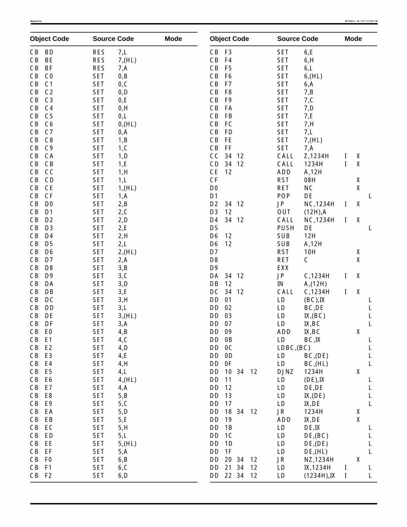
USER'S MANUALZILOG
Object Code Source Code Mode
CB BD RES 7,LCB BE RES 7,(HL)CB BF RES 7,ACB C0 SET 0,BCB C1 SET 0,CCB C2 SET 0,DCB C3 SET 0,ECB C4 SET 0,HCB C5 SET 0,LCB C6 SET 0,(HL)CB C7 SET 0,ACB C8 SET 1,BCB C9 SET 1,CCB CA SET 1,DCB CB SET 1,ECB CC SET 1,HCB CD SET 1,LCB CE SET 1,(HL)CB CF SET 1,ACB D0 SET 2,BCB D1 SET 2,CCB D2 SET 2,DCB D3 SET 2,ECB D4 SET 2,HCB D5 SET 2,LCB D6 SET 2,(HL)CB D7 SET 2,ACB D8 SET 3,BCB D9 SET 3,CCB DA SET 3,DCB DB SET 3,ECB DC SET 3,HCB DD SET 3,LCB DE SET 3,(HL)CB DF SET 3,ACB E0 SET 4,BCB E1 SET 4,CCB E2 SET 4,DCB E3 SET 4,ECB E4 SET 4,HCB E5 SET 4,LCB E6 SET 4,(HL)CB E7 SET 4,ACB E8 SET 5,BCB E9 SET 5,CCB EA SET 5,DCB EB SET 5,ECB EC SET 5,HCB ED SET 5,LCB EE SET 5,(HL)CB EF SET 5,ACB F0 SET 6,BCB F1 SET 6,CCB F2 SET 6,D
Object Code Source Code Mode
CB F3 SET 6,ECB F4 SET 6,HCB F5 SET 6,LCB F6 SET 6,(HL)CB F7 SET 6,ACB F8 SET 7,BCB F9 SET 7,CCB FA SET 7,DCB FB SET 7,ECB FC SET 7,HCB FD SET 7,LCB FE SET 7,(HL)CB FF SET 7,ACC 34 12 CALL Z,1234H I XCD 34 12 CALL 1234H I XCE 12 ADD A,12HCF RST 08H XD0 RET NC XD1 POP DE LD2 34 12 JP NC,1234H I XD3 12 OUT (12H),AD4 34 12 CALL NC,1234H I XD5 PUSH DE LD6 12 SUB 12HD6 12 SUB A,12HD7 RST 10H XD8 RET C XD9 EXXDA 34 12 JP C,1234H I XDB 12 IN A,(12H)DC 34 12 CALL C,1234H I XDD 01 LD (BC),IX LDD 02 LD BC,DE LDD 03 LD IX,(BC) LDD 07 LD IX,BC LDD 09 ADD IX,BC XDD 0B LD BC,IX LDD 0C LD BC,(BC) LDD 0D LD BC,(DE) LDD 0F LD BC,(HL) LDD 10 34 12 DJNZ 1234H XDD 11 LD (DE),IX LDD 12 LD DE,DE LDD 13 LD IX,(DE) LDD 17 LD IX,DE LDD 18 34 12 JR 1234H XDD 19 ADD IX,DE XDD 1B LD DE,IX LDD 1C LD DE,(BC) LDD 1D LD DE,(DE) LDD 1F LD DE,(HL) LDD 20 34 12 JR NZ,1234H XDD 21 34 12 LD IX,1234H I LDD 22 34 12 LD (1234H),IX I L

USER'S MANUALZILOG
Object Code Source Code Mode
DD 23 INC IX XDD 23 INCW IX XDD 24 INC IXUDD 25 DEC IXUDD 26 12 LD IXU,12HDD 27 LD IX,IY LDD 28 34 12 JR Z,1234H XDD 29 ADD IX,IX XDD 2A 34 12 LD IX,(1234H) I LDD 2B DEC IX XDD 2B DECW IX XDD 2C INC IXLDD 2D DEC IXLDD 2E 12 LD IXL,12HDD 2F CPLW HLDD 2F CPLWDD 30 34 12 JR NC,1234H XDD 31 LD (HL),IX LDD 32 LD HL,DE LDD 33 LD IX,(HL) LDD 34 12 INC (IX+12H) IDD 35 12 DEC (IX+12H) IDD 36 12 34 LD (IX+12H),34H IDD 37 LD IX,HL LDD 38 34 12 JR C,1234H XDD 39 ADD IX,SP XDD 3B LD HL,IX LDD 3C LD HL,(BC) LDD 3D LD HL,(DE) LDD 3E SWAP IXDD 3F LD HL,(HL) LDD 40 INW BC,(C)DD 41 OUTW (C),BCDD 44 LD B,IXUDD 45 LD B,IXLDD 46 12 LD B,(IX+12H) IDD 47 LD I,HL LDD 47 LDW I,HL LDD 4C LD C,IXUDD 4D LD C,IXLDD 4E 12 LD C,(IX+12H) IDD 50 INW DE,(C)DD 51 OUTW (C),DEDD 54 LD D,IXUDD 55 LD D,IXLDD 56 12 LD D,(IX+12H) IDD 57 LD HL,I LDD 57 LDW HL,I LDD 5D LD E,IXLDD 5D LD E,IYLDD 5E 12 LD E,(IX+12H) IDD 60 LD IXU,BDD 61 LD IXU,CDD 62 LD IXU,D
Object Code Source Code Mode
DD 63 LD IXU,EDD 64 LD IXU,IXUDD 65 LD IXU,IXLDD 66 12 LD H,(IX+12H) IDD 67 LD IXU,ADD 68 LD IXL,BDD 69 LD IXL,CDD 6A LD IXL,DDD 6B LD IXL,EDD 6C LD IXL,IXUDD 6D LD IXL,IXLDD 6E 12 LD L,(IX+12H) IDD 6F LD IXL,ADD 70 12 LD (IX+12H),B IDD 71 12 LD (IX+12H),C IDD 72 12 LD (IX+12H),D IDD 73 12 LD (IX+12H),E IDD 74 12 LD (IX+12H),H IDD 75 12 LD (IX+12H),L IDD 77 12 LD (IX+12H),A IDD 78 INW HL,(C)DD 79 OUTW (C),HLDD 7C LD A,IXUDD 7D LD A,IXLDD 7E 12 LD A,(IX+12H) IDD 84 ADD A,IXUDD 85 ADD A,IXLDD 86 12 ADD A,(IX+12H) IDD 87 ADDW HL,IXDD 87 ADDW IXDD 8C ADC A,IXUDD 8D ADC A,IXLDD 8E 12 ADC A,(IX+12H) IDD 8F ADCW HL,IXDD 8F ADCW IXDD 94 SUB A,IXUDD 95 SUB A,IXLDD 96 12 SUB A,(IX+12H) IDD 97 SUBW HL,IXDD 97 SUBW IXDD 9C SBC A,IXUDD 9D SBC A,IXLDD 9E 12 SBC A,(IX+12H) IDD 9F SBCW HL,IXDD 9F SBCW IXDD A4 AND A,IXUDD A4 AND IXUDD A5 AND A,IXLDD A5 AND IXLDD A6 12 AND (IX+12H) IDD A6 12 AND A,(IX+12H) IDD A7 ANDW HL,IXDD A7 ANDW IXDD AC XOR A,IXU

USER'S MANUALZILOG
Object Code Source Code Mode
DD AC XOR IXUDD AD XOR A,IXLDD AD XOR IXLDD AE 12 XOR (IX+12H) IDD AE 12 XOR A,(IX+12H) IDD AF XORW HL,IXDD AF XORW IXDD B4 OR A,IXUDD B4 OR IXUDD B5 OR A,IXLDD B5 OR IXLDD B6 12 OR (IX+12H) IDD B6 12 OR A,(IX+12H) IDD B7 ORW HL,IXDD B7 ORW IXDD BC CP A,IXUDD BC CP IXUDD BD CP A,IXLDD BD CP IXLDD BE 12 CP (IX+12H) IDD BE 12 CP A,(IX+12H) IDD BF CPW HL,IXDD BF CPW IXDD C0 DDIR WDD C1 DDIR IB,WDD C2 DDIR IW,WDD C3 DDIR IBDD C4 34 12 CALR NZ,1234H XDD C6 12 ADDW (IX+12H) IDD C6 12 ADDW HL,(IX+12H) IDD C8 LDCTL SR,ADD CA 01 LDCTL SR,01HDD CB 12 01 LD BC,(SP+12H) I LDD CB 12 02 RLCW (IX+12H) IDD CB 12 03 LD BC,(IX+12H) I LDD CB 12 06 RLC (IX+12H) IDD CB 12 09 LD (SP+12H),BC I LDD CB 12 0A RRCW (IX+12H) IDD CB 12 0B LD (IX+12H),BC I LDD CB 12 0E RRC (IX+12H) IDD CB 12 11 LD DE,(SP+12H) I LDD CB 12 12 RLW (IX+12H) IDD CB 12 13 LD DE,(IX+12H) I LDD CB 12 16 RL (IX+12H) IDD CB 12 19 LD (SP+12H),DE I LDD CB 12 1A RRW (IX+12H) IDD CB 12 1B LD (IX+12H),DE I LDD CB 12 1E RR (IX+12H) IDD CB 12 21 LD IX,(SP+12H) I LDD CB 12 22 SLAW (IX+12H) IDD CB 12 23 LD IY,(IX+12H) I LDD CB 12 26 SLA (IX+12H) IDD CB 12 29 LD (SP+12H),IX I LDD CB 12 2A SRAW (IX+12H) I
Object Code Source Code Mode
DD CB 12 2B LD (IX+12H),IY I LDD CB 12 2E SRA (IX+12H) IDD CB 12 31 LD HL,(SP+12H) I LDD CB 12 33 LD HL,(IX+12H) I LDD CB 12 39 LD (SP+12H),HL I LDD CB 12 3A SRLW (IX+12H) IDD CB 12 3B LD (IX+12H),HL I LDD CB 12 3E SRL (IX+12H) IDD CB 12 46 BIT 0,(IX+12H) IDD CB 12 4E BIT 1,(IX+12H) IDD CB 12 56 BIT 2,(IX+12H) IDD CB 12 5E BIT 3,(IX+12H) IDD CB 12 66 BIT 4,(IX+12H) IDD CB 12 6E BIT 5,(IX+12H) IDD CB 12 76 BIT 6,(IX+12H) IDD CB 12 7E BIT 7,(IX+12H) IDD CB 12 86 RES 0,(IX+12H) IDD CB 12 8E RES 1,(IX+12H) IDD CB 12 92 MULTW (IX+12H) IDD CB 12 92 MULTW HL,(IX+12H) IDD CB 12 96 RES 2,(IX+12H) IDD CB 12 9A MULTUW (IX+12H) IDD CB 12 9A MULTUW HL,(IX+12H) IDD CB 12 9E RES 3,(IX+12H) IDD CB 12 A6 RES 4,(IX+12H) IDD CB 12 AE RES 5,(IX+12H) IDD CB 12 B6 RES 6,(IX+12H) IDD CB 12 BA DIVUW (IX+12H) IDD CB 12 BA DIVUW HL,(IX+12H) IDD CB 12 BE RES 7,(IX+12H) IDD CB 12 C6 SET 0,(IX+12H) IDD CB 12 CE SET 1,(IX+12H) IDD CB 12 D6 SET 2,(IX+12H) IDD CB 12 DE SET 3,(IX+12H) IDD CB 12 E6 SET 4,(IX+12H) IDD CB 12 EE SET 5,(IX+12H) IDD CB 12 F6 SET 6,(IX+12H) IDD CB 12 FE SET 7,(IX+12H) IDD CC 34 12 CALR Z,1234H XDD CD 34 12 CALR 1234H XDD CE 12 ADCW (IX+12H) IDD CE 12 ADCW HL,(IX+12H) IDD CF MTESTDD D0 LDCTL A,XSRDD D4 34 12 CALR NC,1234H XDD D6 12 SUBW (IX+12H)DD D6 12 SUBW HL,(IX+12H) IDD D8 LDCTL XSR,ADD D9 EXXXDD DA 01 LDCTL XSR,01HDD DC 34 12 CALR C,1234H XDD DE 12 SBCW (IX+12H) IDD DE 12 SBCW HL,(IX+12H)DD E1 POP IX L

USER'S MANUALZILOG
Object Code Source Code Mode
DD E3 EX (SP),IX LDD E4 34 12 CALR PO,1234H XDD E5 PUSH IX LDD E6 12 ANDW (IX+12H) IDD E6 12 ANDW HL,(IX+12H) IDD E9 JP (IX) XDD EC 34 12 CALR PE,1234H XDD EE 12 XORW (IX+12H) IDD EE 12 XORW HL,(IX+12H) IDD F3 1F DI 1FHDD F4 34 12 CALR P,1234H XDD F6 12 ORW (IX+12H) IDD F6 12 ORW HL,(IX+12H) IDD F7 SETC LWDD F9 LD SP,IX LDD FB 1F EI 1FHDD FC 34 12 CALR M,1234H XDD FE 12 CPW (IX+12H) IDD FE 12 CPW HL,(IX+12H) IDD FF RESC LWDE 12 SBC A,12HDF RST 18H XE0 RET NV XE0 RET PO XE1 POP HL LE2 34 12 JP NV,1234H I XE2 34 12 JP PO,1234H I XE3 EX (SP),HL LE4 34 12 CALL NV, 1234H I XE4 34 12 CALL PO,1234H I XE5 PUSH HL LE6 12 AND 12HE6 12 AND A,12HE7 RST 20H XE8 RET PE XE8 RET V XE9 JP (HL) XEA 34 12 JP PE,1234H I XEA 34 12 JP V,1234H I XEB EX DE,HL LEC 34 12 CALL V, 1234H I XEC 34 12 CALL PE,1234H I XED 00 12 IN0 B,(12H)ED 01 12 OUT0 (12H),BED 02 LD BC,BC LED 03 EX BC,IX LED 04 TST BED 05 EX BC,DE LED 06 34 12 LDW (BC),1234H I LED 07 EX A,BED 08 12 IN0 C,(12H)ED 09 12 OUT0 (12H),CED 0B EX BC,IY LED 0C TST CED 0D EX BC,HL LED 0E SWAP BC
Object Code Source Code Mode
ED 0F EX A,CED 10 12 IN0 D,(12H)ED 11 12 OUT0 (12H),DED 12 LD DE,BC LED 13 EX DE,IX LED 14 TST DED 16 34 12 LDW (DE),1234H I LED 17 EX A,DED 18 12 IN0 E,(12H)ED 19 12 OUT0 (12H),EED 1B EX DE,IY LED 1C TST EED 1E SWAP DEED 1F EX A,EED 20 12 IN0 H,(12H)ED 21 12 OUT0 (12H),HED 24 TST HED 27 EX A,HED 28 12 IN0 L,(12H)ED 29 12 OUT0 (12H),LED 2B EX IX,IY LED 2C TST LED 2F EX A,LED 30 12 IN0 (12H)ED 32 LD HL,BC LED 33 EX HL,IX LED 34 TST (HL)ED 36 34 12 LDW (HL),1234H I LED 37 EX A,(HL)ED 38 12 IN0 A,(12H)ED 39 12 OUT0 (12H),AED 3B EX HL,IY LED 3C TST AED 3E SWAP HLED 3F EX A,AED 40 IN B,(C)ED 41 OUT (C),BED 42 SBC HL,BCED 43 34 12 LD (1234H),BC I LED 44 NEG AED 44 NEGED 45 RETN XED 46 IM 0ED 47 LD I,AED 48 IN C,(C)ED 49 OUT (C),CED 4A ADC HL,BCED 4B 34 12 LD BC,(1234H) I LED 4C MLT BCED 4D RETI XED 4E IM 3ED 4F LD R,AED 50 IN D,(C)ED 51 OUT (C),D

USER'S MANUALZILOG
Object Code Source Code Mode
ED 52 SBC HL,DEED 53 34 12 LD (1234H),DE I LED 54 NEGW HLED 54 NEGWED 55 reservedED 56 IM 1ED 57 LD A,IED 58 IN E,(C)ED 59 OUT (C),EED 5A ADC HL,DEED 5B 34 12 LD DE,(1234H) I LED 5C MLT DEED 5E IM 2ED 5F LD A,RED 60 IN H,(C)ED 61 OUT (C),HED 62 SBC HL,HLED 63 34 12 LD (1234H),HL I LED 64 12 TST 12HED 65 EXTS A LED 65 EXTS LED 67 RRDED 68 IN L,(C)ED 69 OUT (C),LED 6A ADC HL,HLED 6B 34 12 LD HL,(1234H) I LED 6C MLT HLED 6F RLDED 71 12 OUT (C),12HED 72 SBC HL,SPED 73 34 12 LD (1234H),SP I LED 74 12 TSTIO 12HED 75 EXTSW HLED 75 EXTSWED 76 SLPED 78 IN A,(C)ED 79 OUT (C),AED 7A ADC HL,SPED 7B 34 12 LD SP,(1234H) I LED 7C MLT SPED 82 34 12 ADD SP,1234H I XED 83 OTIMED 84 ADDW BCED 84 ADDW HL,BCED 85 ADDW DEED 85 ADDW HL,DEED 86 34 12 ADDW 1234HED 86 34 12 ADDW HL,1234HED 87 ADDW HLED 87 ADDW HL,HLED 8B OTDMED 8C ADCW BCED 8C ADCW HL,BCED 8D ADCW DE
Object Code Source Code Mode
ED 8D ADCW HL,DEED 8E 34 12 ADCW 1234HED 8E 34 12 ADCW HL,1234HED 8F ADCW HLED 8F ADCW HL,HLED 92 34 12 SUB SP,1234H I XED 93 OTIMRED 94 SUBW BCED 94 SUBW HL,BCED 95 SUBW DEED 95 SUBW HL,DEED 96 34 12 SUBW 1234HED 96 34 12 SUBW HL,1234HED 97 SUBW HLED 97 SUBW HL,HLED 9B OTDMRED 9C SBCW BCED 9C SBCW HL,BCED 9D SBCW DEED 9D SBCW HL,DEED 9E 34 12 SBCW 1234HED 9E 34 12 SBCW HL,1234HED 9F SBCW HLED 9F SBCW HL,HLED A0 LDIED A1 CPI XED A2 INIED A3 OUTIED A4 ANDW BCED A4 ANDW HL,BCED A5 ANDW DEED A5 ANDW HL,DEED A6 34 12 ANDW 1234HED A6 34 12 ANDW HL,1234HED A7 ANDW HLED A7 ANDW HL,HLED A8 LDDED A9 CPD XED AA INDED AB OUTDED AC XORW BCED AC XORW HL,BCED AD XORW DEED AD XORW HL,DEED AE 34 12 XORW 1234HED AE 34 12 XORW HL,1234HED AF XORW HLED AF XORW HL,HLED B0 LDIRED B1 CPIR XED B2 INIRED B3 OTIRED B4 ORW BCED B4 ORW HL,BC

USER'S MANUALZILOG
Object Code Source Code Mode
ED B5 ORW DEED B5 ORW HL,DEED B6 34 12 ORW 1234HED B6 34 12 ORW HL,1234HED B7 ORW HLED B7 ORW HL,HLED B8 LDDRED B9 CPDR XED BA INDRED BB OTDRED BC CPW BCED BC CPW HL,BCED BD CPW DEED BD CPW HL,DEED BE 34 12 CPW 1234HED BE 34 12 CPW HL,1234HED BF CPW HLED BF CPW HL,HLED C0 LDCTL HL,SR LED C1 POP SR LED C4 12 CALR NZ,12H XED C5 PUSH SR LED C6 34 12 ADD HL,(1234H) I XED C8 LDCTL SR,HL LED CB 00 RLCW BCED CB 01 RLCW DEED CB 02 RLCW (HL)ED CB 03 RLCW HLED CB 04 RLCW IXED CB 05 RLCW IYED CB 08 RRCW BCED CB 09 RRCW DEED CB 0A RRCW (HL)ED CB 0B RRCW HLED CB 0C RRCW IXED CB 0D RRCW IYED CB 10 RLW BCED CB 11 RLW DEED CB 12 RLW (HL)ED CB 13 RLW HLED CB 14 RLW IXED CB 15 RLW IYED CB 18 RRW BCED CB 19 RRW DEED CB 1A RRW (HL)ED CB 1B RRW HLED CB 1C RRW IXED CB 1D RRW IYED CB 20 SLAW BCED CB 21 SLAW DEED CB 22 SLAW (HL)ED CB 23 SLAW HLED CB 24 SLAW IXED CB 25 SLAW IY
Object Code Source Code Mode
ED CB 28 SRAW BCED CB 29 SRAW DEED CB 2A SRAW (HL)ED CB 2B SRAW HLED CB 2C SRAW IXED CB 2D SRAW IYED CB 30 EX BC,BC’ LED CB 31 EX DE,DE’ LED CB 33 EX HL,HL’ LED CB 34 EX IX,IX’ED CB 35 EX IY,IY’ LED CB 38 SRLW BCED CB 39 SRLW DEED CB 3A SRLW (HL)ED CB 3B SRLW HLED CB 3C SRLW IXED CB 3D SRLW IYED CB 90 MULTW BCED CB 90 MULTW HL,BCED CB 91 MULTW DEED CB 91 MULTW HL,DEED CB 93 MULTW HLED CB 93 MULTW HL,HLED CB 94 MULTW HL,IXED CB 94 MULTW IXED CB 95 MULTW HL,IYED CB 95 MULTW IYED CB 97 34 12 MULTW 1234HED CB 97 34 12 MULTW HL,1234HED CB 98 MULTUW BCED CB 98 MULTUW HL,BCED CB 99 MULTUW DEED CB 99 MULTUW HL,DEED CB 9B MULTUW HLED CB 9B MULTUW HL,HLED CB 9C MULTUW HL,IXED CB 9C MULTUW IXED CB 9D MULTUW HL,IYED CB 9D MULTUW IYED CB 9F MULTUW 1234HED CB 9F MULTUW HL,1234HED CB B8 DIVUW BCED CB B8 DIVUW HL,BCED CB B9 DIVUW DEED CB B9 DIVUW HL,DEED CB BB DIVUW HLED CB BB DIVUW HL,HL

USER'S MANUALZILOG
Object Code Source Code Mode
ED CB BC DIVUW HL,IXED CB BC DIVUW IXED CB BD DIVUW HL,IYED CB BD DIVUW IYED CB BF DIVUW 1234HED CB BF DIVUW HL,1234HED CC 12 CALR Z,12H XED CD 12 CALR 12H XED CF BTESTED D0 LDCTL A,DSRED D3 34 12 OUTA (1234H),A IED D4 12 CALR NC,12H XED D6 34 12 SUB HL,(1234H) I XED D8 LDCTL DSR,AED D9 EXALLED DA 01 LDCTL DSR,01HED DB 34 12 INA A,(1234H) IED DC 12 CALR C,12H XED E0 LDIW LED E2 INIWED E3 OUTIWED E4 12 CALR PO,12H XED E8 LDDW LED EA INDWED EB OUTDWED EC 12 CALR PE,12H XED F0 LDIRW LED F2 INIRWED F3 OTIRWED F4 12 CALR P,12H XED F7 SETC LCKED F8 LDDRW LED FA INDRWED FB OTDRWED FC 12 CALR M,12H XED FF RESC LCKEE 12 XOR 12HEE 12 XOR A,12HEF RST 28H XF0 RET NS XF0 RET P XF1 POP AF LF2 34 12 JP NS,1234H I XF2 34 12 JP P,1234H I XF3 DIF4 34 12 CALL NS P,1234H I XF5 PUSH AF LF6 12 OR 12HF6 12 OR A,12HF7 RST 30H XF8 RET M XF8 RET S XF9 LD SP,HL LFA 34 12 JP M,1234H I X
Object Code Source Code Mode
FA 34 12 JP S,1234H I XFB EIFC 34 12 CALL S, M,1234H I XFD 01 LD (BC),IY LFD 02 LD BC,HL LFD 03 LD IY,(BC) LFD 07 LD IY,BC LFD 09 ADD IY,BC XFD 0B LD BC,IY LFD 0C LD (BC),BC LFD 0D LD (DE),BC LFD 0F LD (HL),BC LFD 10 56 34 12 DJNZ 123456H XFD 11 LD (DE),IY LFD 12 LD DE,HL LFD 13 LD IY,(DE) LFD 17 LD IY,DE LFD 18 56 34 12 JR 123456H XFD 19 ADD IY,DE XFD 1B LD DE,IY LFD 1C LD (BC),DE LFD 1D LD (DE),DE LFD 1F LD (HL),DE LFD 20 56 34 12 JR NZ,123456H XFD 21 34 12 LD IY,1234H I LFD 22 34 12 LD (1234H),IY I LFD 23 INC IY XFD 23 INCW IY XFD 24 INC IYUFD 25 DEC IYUFD 27 LD IY,IX LFD 28 56 34 12 JR Z,123456H XFD 29 ADD IY,IY XFD 2A 34 12 LD IY,(1234H) I LFD 2B DEC IY XFD 2B DECW IY XFD 2C INC IYLFD 2D DEC IYLFD 2E 12 LD IYL,12HFD 30 56 34 12 JR NC,123456H XFD 31 LD (HL),IY LFD 32 LD HL,HL LFD 33 LD IY,(HL) LFD 34 12 INC (IY+12H) IFD 35 12 DEC (IY+12H) IFD 36 34 12 LD (IY+12H),34H IFD 36 12 LD IYU,12HFD 37 LD IY,HL LFD 38 56 34 12 JR C,123456H XFD 39 ADD IY,SP XFD 3B LD HL,IY LFD 3C LD (BC),HL LFD 3D LD (DE),HL LFD 3E SWAP IY

USER'S MANUALZILOG
Object Code Source Code Mode
FD 3F LD (HL),HL LFD 44 LD B,IYUFD 45 LD B,IYLFD 46 12 LD B,(IY+12H) IFD 4C LD C,IYUFD 4D LD C,IYLFD 4E 12 LD C,(IY+12H) IFD 54 LD D,IYUFD 55 LD D,IYLFD 56 12 LD D,(IY+12H) IFD 5C LD E,IYUFD 5D LD E,IYLFD 5E 12 LD E,(IY+12H) IFD 60 LD IYU,BFD 61 LD IYU,CFD 62 LD IYU,DFD 63 LD IYU,EFD 64 LD IYU,IYUFD 65 LD IYU,IYLFD 66 12 LD H,(IY+12H) IFD 67 LD IYU,AFD 68 LD IYL,BFD 69 LD IYL,CFD 6A LD IYL,DFD 6B LD IYL,EFD 6C LD IYL,IYUFD 6D LD IYL,IYLFD 6E 12 LD L,(IY+12H) IFD 6F LD IYL,AFD 70 12 LD (IY+12H),B IFD 71 12 LD (IY+12H),C IFD 72 12 LD (IY+12H),D IFD 73 12 LD (IY+12H),E I LFD 74 12 LD (IY+12H),H IFD 75 12 LD (IY+12H),L IFD 77 12 LD (IY+12H),A IFD 79 34 12 OUTW (C),1234HFD 7C LD A,IYUFD 7D LD A,IYLFD 7E 12 LD A,(IY+12H) IFD 84 ADD A,IYUFD 85 ADD A,IYLFD 86 12 ADD A,(IY+12H) IFD 87 ADDW HL,IYFD 87 ADDW IYFD 8C ADC A,IYUFD 8D ADC A,IYLFD 8E 12 ADC A,(IY+12H) IFD 8F ADCW HL,IYFD 8F ADCW IYFD 94 SUB A,IYUFD 95 SUB A,IYLFD 96 12 SUB A,(IY+12H) IFD 97 SUBW HL,IY
Object Code Source Code Mode
FD 97 SUBW IYFD 9C SBC A,IYUFD 9D SBC A,IYLFD 9E 12 SBC A,(IY+12H) IFD 9F SBCW HL,IYFD 9F SBCW IYFD A4 AND A,IYUFD A4 AND IYUFD A5 AND A,IYLFD A5 AND IYLFD A6 12 AND (IY+12H) IFD A6 12 AND A,(IY+12H) IFD A7 ANDW HL,IYFD A7 ANDW IYFD AC XOR A,IYUFD AC XOR IYUFD AD XOR A,IYLFD AD XOR IYLFD AE 12 XOR (IY+12H) IFD AE 12 XOR A,(IY+12H) IFD AF XORW HL,IYFD AF XORW IYFD B4 OR A,IYUFD B4 OR IYUFD B5 OR A,IYLFD B5 OR IYLFD B6 12 OR (IY+12H) IFD B6 12 OR A,(IY+12H) IFD B7 ORW HL,IYFD B7 ORW IYFD BC CP A,IYUFD BC CP IYUFD BD CP A,IYLFD BD CP IYLFD BE 12 CP (IY+12H) IFD BE 12 CP A,(IY+12H) IFD BF CPW HL,IYFD BF CPW IYFD C0 DDIR LWFD C1 DDIR IB,LWFD C2 DDIR IW,LWFD C3 DDIR IWFD C4 56 34 12 CALR NZ,123456H XFD C6 12 ADDW (IY+12H) IFD C6 12 ADDW HL,(IY+12H) IFD CB 12 02 RLCW (IY+12H) IFD CB 12 03 LD BC,(IY+12H) I LFD CB 12 06 RLC (IY+12H) IFD CB 12 0A RRCW (IY+12H) IFD CB 12 0B LD (IY+12H),BC I LFD CB 12 0E RRC (IY+12H) IFD CB 12 12 RLW (IY+12H) IFD CB 12 13 LD DE,(IY+12H) I LFD CB 12 16 RL (IY+12H) I

USER'S MANUALZILOG
Object Code Source Code Mode
FD CB 12 1A RRW (IY+12H) IFD CB 12 1B LD (IY+12H),DE IFD CB 12 1E RR (IY+12H) IFD CB 12 21 LD IY,(SP+12H) I LFD CB 12 22 SLAW (IY+12H) IFD CB 12 23 LD IX,(IY+12H) I LFD CB 12 26 SLA (IY+12H) IFD CB 12 29 LD (SP+12H),IY I LFD CB 12 2A SRAW (IY+12H) IFD CB 12 2B LD (IY+12H),IX I LFD CB 12 2E SRA (IY+12H) IFD CB 12 33 LD HL,(IY+12H) I LFD CB 12 3A SRLW (IY+12H) IFD CB 12 3B LD (IY+12H),HL I LFD CB 12 3E SRL (IY+12H) IFD CB 12 46 BIT 0,(IY+12H) IFD CB 12 4E BIT 1,(IY+12H) IFD CB 12 56 BIT 2,(IY+12H) IFD CB 12 5E BIT 3,(IY+12H) IFD CB 12 66 BIT 4,(IY+12H) IFD CB 12 6E BIT 5,(IY+12H) IFD CB 12 76 BIT 6,(IY+12H) IFD CB 12 7E BIT 7,(IY+12H) IFD CB 12 86 RES 0,(IY+12H) IFD CB 12 8E RES 1,(IY+12H) IFD CB 12 92 MULTW (IY+12H) IFD CB 12 92 MULTW HL,(IY+12H) IFD CB 12 96 RES 2,(IY+12H) IFD CB 12 9A MULTUW (IY+12H) IFD CB 12 9A MULTUW HL,(IY+12H) IFD CB 12 9E RES 3,(IY+12H) IFD CB 12 A6 RES 4,(IY+12H) IFD CB 12 AE RES 5,(IY+12H) IFD CB 12 B6 RES 6,(IY+12H) IFD CB 12 BA DIVUW (IY+12H) IFD CB 12 BA DIVUW HL,(IY+12H) IFD CB 12 BE RES 7,(IY+12H) IFD CB 12 C6 SET 0,(IY+12H) IFD CB 12 CE SET 1,(IY+12H) IFD CB 12 D6 SET 2,(IY+12H) IFD CB 12 DE SET 3,(IY+12H) IFD CB 12 E6 SET 4,(IY+12H) IFD CB 12 EE SET 5,(IY+12H) IFD CB 12 F6 SET 6,(IY+12H) IFD CB 12 FE SET 7,(IY+12H) IFD CC 56 34 12 CALR Z,123456H XFD CD 56 34 12 CALR 123456H XFD CE 12 ADCW (IY+12H) IFD CE 12 ADCW HL,(IY+12H) IFD D0 LDCTL A,YSRFD D3 34 12 OUTAW (1234H),HL IFD D4 56 34 12 CALR NC,123456H XFD D6 12 SUBW (IY+12H)FD D6 12 SUBW HL,(IY+12H) I
Object Code Source Code Mode
FD D8 LDCTL YSR,AFD D9 EXXYFD DA 01 LDCTL YSR,01HFD DB 34 12 INAW HL,(1234H) IFD DC 56 34 12 CALR C,123456H XFD DE 12 SBCW (IY+12H) IFD DE 12 SBCW HL,(IY+12H)FD E1 POP IY LFD E3 EX (SP),IY LFD E4 56 34 12 CALR PO,123456H XFD E5 PUSH IY LFD E6 12 ANDW (IY+12H) IFD E6 12 ANDW HL,(IY+12H) IFD E9 JP (IY) XFD EC 56 34 12 CALR PE,123456H XFD EE 12 XORW (IY+12H) IFD EE 12 XORW HL,(IY+12H) IFD F4 56 34 12 CALR P,123456H XFD F5 34 12 PUSH 1234H I LFD F6 12 ORW (IY+12H) IFD F6 12 ORW HL,(IY+12H) IFD F7 SETC XMFD F9 LD SP,IY LFD FC CALR M,123456H XFD FE 12 CPW (IY+12H) IFD FE 12 CPW HL,(IY+12H) IFE 12 CP 12HFE 12 CP A,12HFF RST 38H X

USER'S MANUALZILOG
Zilog’s products are not authorized for use as critical compo-nents in life support devices or systems unless a specific writtenagreement pertaining to such intended use is executed betweenthe customer and Zilog prior to use. Life support devices orsystems are those which are intended for surgical implantationinto the body, or which sustains life whose failure to perform,when properly used in accordance with instructions for useprovided in the labeling, can be reasonably expected to result insignificant injury to the user.
Zilog, Inc. 210 East Hacienda Ave.Campbell, CA 95008-6600Telephone (408) 370-8000Telex 910-338-7621FAX 408 370-8056Internet: http://www.zilog.com
© 1994, 1995, 1996, 1997 by Zilog, Inc. All rights reserved. Nopart of this document may be copied or reproduced in any formor by any means without the prior written consent of Zilog, Inc.The information in this document is subject to change withoutnotice. Devices sold by Zilog, Inc. are covered by warranty andpatent indemnification provisions appearing in Zilog, Inc. Termsand Conditions of Sale only.
ZILOG, INC. MAKES NO WARRANTY, EXPRESS, STATUTORY,IMPLIED OR BY DESCRIPTION, REGARDING THE INFORMA-TION SET FORTH HEREIN OR REGARDING THE FREEDOM OFTHE DESCRIBED DEVICES FROM INTELLECTUAL PROPERTYINFRINGEMENT. ZILOG, INC. MAKES NO WARRANTY OF MER-CHANTABILITY OR FITNESS FOR ANY PURPOSE.
Zilog, Inc. shall not be responsible for any errors that may appearin this document. Zilog, Inc. makes no commitment to update orkeep current the information contained in this document.

USER'S MANUALZILOG
USER’s MANUAL
This Appendix has two sets of tables. Each table is asubset of the Table in the Appendix B. The Table D-1 hasthe instructions which works differently in the Native and
Extended mode of operation, and the Table D-2 has theinstructions which works differently in Word/Long Wordmode of operation.
APPENDIX DINSTRUCTIONS AFFECTED BY NORMAL/EXTENDED MODE, AND LONG WORD MODE

USER'S MANUALZILOG
Table D-1. Instructions operating differently inNative or Extended mode of operation.
Source Code Object Code
ADD HL,BC 09ADD HL,DE 19ADD HL,HL 29ADD HL,SP 39ADD IX,BC DD 09ADD IX,DE DD 19ADD IX,IX DD 29ADD IX,SP DD 39ADD IY,BC FD 09ADD IY,DE FD 19ADD IY,IY FD 29ADD IY,SP FD 39CALR 123456H FD CD 56 34 12CALR 1234H DD CD 34 12CALR 12H ED CD 12CALR C,123456H FD DC 56 34 12CALR C,1234H DD DC 34 12CALR C,12H ED DC 12CALR M,123456H FD FCCALR M,1234H DD FC 34 12CALR M,12H ED FC 12CALR NC,123456H FD D4 56 34 12CALR NC,1234H DD D4 34 12CALR NC,12H ED D4 12CALR NZ,123456H FD C4 56 34 12CALR NZ,1234H DD C4 34 12CALR NZ,12H ED C4 12CALR P,123456H FD F4 56 34 12CALR P,1234H DD F4 34 12CALR P,12H ED F4 12CALR PE,123456H FD EC 56 34 12CALR PE,1234H DD EC 34 12CALR PE,12H ED EC 12CALR PO,123456H FD E4 56 34 12CALR PO,1234H DD E4 34 12CALR PO,12H ED E4 12CALR Z,123456H FD CC 56 34 12CALR Z,1234H DD CC 34 12CALR Z,12H ED CC 12CPD ED A9CPDR ED B9CPI ED A1CPIR ED B1DEC BC 0BDEC DE 1BDEC HL 2BDEC IX DD 2BDEC IY FD 2BDEC SP 3BDECW BC 0B
Source Code Object Code
DECW DE 1BDECW HL 2BDECW IX DD 2BDECW IY FD 2BDECW SP 3BDJNZ 123456H FD 10 56 34 12DJNZ 1234H DD 10 34 12DJNZ 12H 10 12INC BC 03INC DE 13INC HL 23INC IX DD 23INC IY FD 23INC SP 33INCW BC 03INCW DE 13INCW HL 23INCW IX DD 23INCW IY FD 23INCW SP 33JP (HL) E9JP (IX) DD E9JP (IY) FD E9JR 123456H FD 18JR 1234H DD 18 34 12JR 12H 18 12JR C,123456H FD 38 56 34 12JR C,1234H DD 38 34 12JR C,12H 38 12JR NC,123456H FD 30 56 34 12JR NC,1234H DD 30 34 12JR NZ,123456H FD 20 56 34 12JR NZ,1234H DD 20 34 12JR NZ,12H 20 12JR Z,123456H FD 28 56 34 12JR Z,1234H DD 28 34 12JR Z,12H 28 12RET C D8RET M F8RET NC D0RET NS F0RET NV E0RET NZ C0RET P F0RET PE E8RET PO E0RET S F8RET V E8RET Z C8RET C9RETI ED 4D

USER'S MANUALZILOG
Source Code Object Code
RETN ED 45RST 00H C7RST 08H CFRST 10H D7RST 18H DFRST 20H E7RST 28H EFRST 30H F7RST 38H FF
Table D-2. Instructions operates different in LongWord Modes.
Source Code Object Code
EX (SP),HL E3EX (SP),IX DD E3EX (SP),IY FD E3EX BC,BC’ ED CB 30EX BC,DE ED 05EX BC,HL ED 0DEX BC,IX ED 03EX BC,IY ED 0BEX DE,DE’ ED CB 31EX DE,HL EBEX DE,IX ED 13EX DE,IY ED 1BEX HL,HL’ ED CB 33EX HL,IX ED 33EX HL,IY ED 3BEX IX,IX’ ED CB 34EX IX,IY ED 2BEX IY,IY’ ED CB 35EXTS A ED 65EXTS ED 65LD (BC),BC FD 0CLD (BC),DE FD 1CLD (BC),HL FD 3CLD (BC),IX DD 01LD (BC),IY FD 01LD (DE),BC FD 0DLD (DE),DE FD 1DLD (DE),HL FD 3DLD (DE),IX DD 11LD (DE),IY FD 11LD (HL),BC FD 0FLD (HL),DE FD 1FLD (HL),HL FD 3FLD (HL),IX DD 31LD (HL),IY FD 31LD BC,(BC) DD 0CLD BC,(DE) DD 0DLD BC,(HL) DD 0FLD BC,BC ED 02
Source Code Object Code
LD BC,DE DD 02LD BC,HL FD 02LD BC,IX DD 0BLD BC,IY FD 0BLD DE,(BC) DD 1CLD DE,(DE) DD 1DLD DE,(HL) DD 1FLD DE,BC ED 12LD DE,DE DD 12LD DE,HL FD 12LD DE,IX DD 1BLD DE,IY FD 1BLD HL,(BC) DD 3CLD HL,(DE) DD 3DLD HL,(HL) DD 3FLD HL,BC ED 32LD HL,DE DD 32LD HL,HL FD 32LD HL,I DD 57LD HL,IX DD 3BLD HL,IY FD 3BLD I,HL DD 47LD IX,(BC) DD 03LD IX,(DE) DD 13LD IX,(HL) DD 33LD IX,BC DD 07LD IX,DE DD 17LD IX,HL DD 37LD IX,IY DD 27LD IY,(BC) FD 03LD IY,(DE) FD 13LD IY,(HL) FD 33LD IY,BC FD 07LD IY,DE FD 17LD IY,HL FD 37LD IY,IX FD 27LD SP,HL F9LD SP,IX DD F9LD SP,IY FD F9

USER'S MANUALZILOG
Source Code Object Code
LDCTL HL,SR ED C0LDCTL SR,HL ED C8LDDRW ED F8LDDW ED E8LDIRW ED F0LDIW ED E0LDW HL,I DD 57LDW I,HL DD 47POP AF F1POP BC C1POP DE D1POP HL E1POP IX DD E1POP IY FD E1POP SR ED C1PUSH AF F5PUSH BC C5PUSH DE D5PUSH HL E5PUSH IX DD E5PUSH IY FD E5PUSH SR ED C5
Zilog’s products are not authorized for use as critical compo-nents in life support devices or systems unless a specific writtenagreement pertaining to such intended use is executed betweenthe customer and Zilog prior to use. Life support devices orsystems are those which are intended for surgical implantationinto the body, or which sustains life whose failure to perform,when properly used in accordance with instructions for useprovided in the labeling, can be reasonably expected to result insignificant injury to the user.
Zilog, Inc. 210 East Hacienda Ave.Campbell, CA 95008-6600Telephone (408) 370-8000Telex 910-338-7621FAX 408 370-8056Internet: http://www.zilog.com
© 1994, 1995, 1996, 1997 by Zilog, Inc. All rights reserved. Nopart of this document may be copied or reproduced in any formor by any means without the prior written consent of Zilog, Inc.The information in this document is subject to change withoutnotice. Devices sold by Zilog, Inc. are covered by warranty andpatent indemnification provisions appearing in Zilog, Inc. Termsand Conditions of Sale only.
ZILOG, INC. MAKES NO WARRANTY, EXPRESS, STATUTORY,IMPLIED OR BY DESCRIPTION, REGARDING THE INFORMA-TION SET FORTH HEREIN OR REGARDING THE FREEDOM OFTHE DESCRIBED DEVICES FROM INTELLECTUAL PROPERTYINFRINGEMENT. ZILOG, INC. MAKES NO WARRANTY OF MER-CHANTABILITY OR FITNESS FOR ANY PURPOSE.
Zilog, Inc. shall not be responsible for any errors that may appearin this document. Zilog, Inc. makes no commitment to update orkeep current the information contained in this document.

USER'S MANUALZILOG
USER’s MANUAL
APPENDIX EINSTRUCTIONS AFFECTED BYDDIR IM INSTRUCTIONS
This Appendix has instructions which can be used with theDecoder Directive(s) Extend Immediate. There are eighttables (E1-E8) which are the subset of the Table A, sortedby the category of the instruction.
Note that the instructions listed here does not have theDDIR Decoder Directive in front of the instructions listedbelow, and notation used here may be different by theassembler to be used.
Table E-1. Valid with DDIR IB in Extended mode. LWbit status does not affect the operation
ADD HL,(123456H) ED C6 56 34 12ADD SP,123456H ED 82 56 34 12CALL 123456H CD 56 34 12CALL C,123456H DC 56 34 12CALL M,123456H FC 56 34 12CALL NC,123456H D4 56 34 12CALL NZ,123456H C4 56 34 12CALL P,123456H F4 56 34 12CALL PE,123456H EC 56 34 12CALL PO,123456H E4 56 34 12CALL Z,123456H CC 56 34 12JP 123456H C3 56 34 12JP C,123456H DA 56 34 12JP M,123456H FA 56 34 12JP NC,123456H D2 56 34 12JP NS,123456H F2 56 34 12JP NV,123456H E2 56 34 12JP NZ,123456H C2 56 34 12JP P,123456H F2 56 34 12JP PE,123456H EA 56 34 12JP PO,123456H E2 56 34 12JP S,123456H FA 56 34 12JP V,123456H EA 56 34 12JP Z,123456H CA 56 34 12SUB HL,(123456H) ED D6 56 34 12SUB SP,123456H ED 92 56 34 12
Table E-2. Valid with DDIR IB. XM bit status does notaffect the operation. Transfer size determined by LWbit. (Either with DDIR IB, DDIR IB,LW or DDIR IB,W)
LD (123456H),BC ED 43 56 34 12LD (123456H),DE ED 53 56 34 12LD (123456H),HL 22 56 34 12LD (123456H),HL ED 63 56 34 12LD (123456H),IX DD 22 56 34 12LD (123456H),IY FD 22 56 34 12LD (123456H),SP ED 73 56 34 12LD (IX+1234H),BC DD CB 34 12 0BLD (IX+1234H),DE DD CB 34 12 1BLD (IX+1234H),HL DD CB 34 12 3BLD (IX+1234H),IY DD CB 34 12 2BLD (IY+1234H),BC FD CB 34 12 0BLD (IY+1234H),E FD 73 34 12LD (IY+1234H),HL FD CB 34 12 3BLD (IY+1234H),IX FD CB 34 12 2BLD (SP+1234H),BC DD CB 34 12 09LD (SP+1234H),DE DD CB 34 12 19LD (SP+1234H),HL DD CB 34 12 39LD (SP+1234H),IX DD CB 34 12 29LD (SP+1234H),IY FD CB 34 12 29LD BC,(123456H) ED 4B 56 34 12LD BC,(IX+1234H) DD CB 34 12 03LD BC,(IY+1234H) FD CB 34 12 03LD BC,(SP+1234H) DD CB 34 12 01LD DE,(123456H) ED 5B 56 34 12LD DE,(IX+1234H) DD CB 34 12 13LD DE,(IY+1234H) FD CB 34 12 13LD DE,(SP+1234H) DD CB 34 12 11LD HL,(123456H) 2A 56 34 12LD HL,(123456H) ED 6B 56 34 12LD HL,(IX+1234H) DD CB 34 12 33LD HL,(IY+1234H) FD CB 34 12 33LD HL,(SP+1234H) DD CB 34 12 31LD IX,(123456H) DD 2A 56 34 12LD IX,(IY+1234H) FD CB 34 12 23LD IX,(SP+1234H) DD CB 34 12 21LD IY,(123456H) FD 2A 56 34 12LD IY,(IX+1234H) DD CB 34 12 23LD IY,(SP+1234H) FD CB 34 12 21LD SP,(123456H) ED 7B 56 34 12LDW (BC),123456H ED 06 56 34 12LDW (DE),123456H ED 16 56 34 12LDW (HL),123456H ED 36 56 34 12

USER'S MANUALZILOG
Table E-3. Valid with DDIR IB in Long Word mode.XM bit status does not affect the operation. (Either
with DDIR IB,LW or DDIR IB with LW bit set.)
LD BC,123456H 01 56 34 12LD DE,123456H 11 56 34 12LD HL,123456H 21 56 34 12LD IX,123456H DD 21 56 34 12LD IY,123456H FD 21 56 34 12LD SP,123456H 31 56 34 12PUSH 123456H FD F5 56 34 12
Table E-4. Valid with DDIR IB. XM bit nor LW bitstatus do not affect the operation
ADC A,(IX+1234H) DD 8E 34 12ADC A,(IY+1234H) FD 8E 34 12ADCW (IX+1234H) DD CE 34 12ADCW (IY+1234H) FD CE 34 12ADCW HL,(IX+1234H) DD CE 34 12ADCW HL,(IY+1234H) FD CE 34 12ADD A,(IX+1234H) DD 86 34 12ADD A,(IY+1234H) FD 86 34 12ADDW (IX+1234H) DD C6 34 12ADDW (IY+1234H) FD C6 34 12ADDW HL,(IX+1234H) DD C6 34 12ADDW HL,(IY+1234H) FD C6 34 12AND (IX+1234H) DD A6 34 12AND (IY+1234H) FD A6 34 12AND A,(IX+1234H) DD A6 34 12AND A,(IY+1234H) FD A6 34 12ANDW (IX+1234H) DD E6 34 12ANDW (IY+1234H) FD E6 34 12ANDW HL,(IX+1234H) DD E6 34 12ANDW HL,(IY+1234H) FD E6 34 12BIT 0,(IX+1234H) DD CB 34 12 46BIT 0,(IY+1234H) FD CB 34 12 46BIT 1,(IX+1234H) DD CB 34 12 4EBIT 1,(IY+1234H) FD CB 34 12 4EBIT 2,(IX+1234H) DD CB 34 12 56BIT 2,(IY+1234H) FD CB 34 12 56BIT 3,(IX+1234H) DD CB 34 12 5EBIT 3,(IY+1234H) FD CB 34 12 5EBIT 4,(IX+1234H) DD CB 34 12 66BIT 4,(IY+1234H) FD CB 34 12 66BIT 5,(IX+1234H) DD CB 34 12 6EBIT 5,(IY+1234H) FD CB 34 12 6EBIT 6,(IX+1234H) DD CB 34 12 76BIT 6,(IY+1234H) FD CB 34 12 76BIT 7,(IX+1234H) DD CB 34 12 7EBIT 7,(IY+1234H) FD CB 34 12 7ECP (IX+1234H) DD BE 34 12CP (IY+1234H) FD BE 34 12CP A,(IX+1234H) DD BE 34 12CP A,(IY+1234H) FD BE 34 12
CPW (IX+1234H) DD FE 34 12CPW (IY+1234H) FD FE 34 12CPW HL,(IX+1234H) DD FE 34 12CPW HL,(IY+1234H) FD FE 34 12DEC (IX+1234H) DD 35 34 12DEC (IY+1234H) FD 35 34 12DIVUW (IX+1234H) DD CB 34 12 BADIVUW (IY+1234H) FD CB 34 12 BADIVUW HL,(IX+1234H) DD CB 34 12 BADIVUW HL,(IY+1234H) FD CB 34 12 BAINA A,(123456H) ED DB 34 12INAW HL,(123456H) FD DB 34 12INC (IX+1234H) DD 34 12INC (IY+1234H) FD 34 12LD (123456H),A 32 56 34 12LD (IX+1234H),56H DD 36 34 12 56LD (IX+1234H),A DD 77 34 12LD (IX+1234H),B DD 70 34 12LD (IX+1234H),C DD 71 34 12LD (IX+1234H),D DD 72 34 12LD (IX+1234H),E DD 73 34 12LD (IX+1234H),H DD 74 34 12LD (IX+1234H),L DD 75 34 12LD (IY+1234H),56H FD 36 34 12 56LD (IY+1234H),A FD 77 34 12LD (IY+1234H),B FD 70 34 12LD (IY+1234H),C FD 71 34 12LD (IY+1234H),D FD 72 34 12LD (IY+1234H),DE FD CB 34 12 1BLD (IY+1234H),H FD 74 34 12LD (IY+1234H),L FD 75 34 12LD A,(1234H) 3A 34 34 12LD A,(IX+1234H) DD 7E 34 12LD A,(IY+1234H) FD 7E 34 12LD B,(IX+1234H) DD 46 34 12LD B,(IY+1234H) FD 46 34 12LD C,(IX+1234H) DD 4E 34 12LD C,(IY+1234H) FD 4E 34 12LD D,(IX+1234H) DD 56 34 12LD D,(IY+1234H) FD 56 34 12LD E,(IX+1234H) DD 5E 34 12LD E,(IY+1234H) FD 5E 34 12LD H,(IX+1234H) DD 66 34 12LD H,(IY+1234H) FD 66 34 12LD L,(IX+1234H) DD 6E 34 12LD L,(IY+1234H) FD 6E 34 12MULTUW (IX+1234H) DD CB 34 12 9AMULTUW (IY+1234H) FD CB 34 12 9AMULTUW HL,(IX+1234H) DD CB 34 12 9AMULTUW HL,(IY+1234H) FD CB 34 12 9AMULTW (IX+1234H) DD CB 34 12 92MULTW (IY+1234H) FD CB 34 12 92MULTW HL,(IX+1234H) DD CB 34 12 92MULTW HL,(IY+1234H) FD CB 34 12 92OR (IX+1234H) DD B6 34 12

USER'S MANUALZILOG
OR (IY+1234H) FD B6 34 12OR A,(IX+1234H) DD B6 34 12OR A,(IY+1234H) FD B6 34 12ORW (IX+1234H) DD F6 34 12ORW (IY+1234H) FD F6 34 12ORW HL,(IX+1234H) DD F6 34 12ORW HL,(IY+1234H) FD F6 34 12OUTA (123456H),A ED D3 56 34 12OUTAW (123456H),HL FD D3 56 34 12RES 0,(IX+1234H) DD CB 34 12 86RES 0,(IY+1234H) FD CB 34 12 86RES 1,(IX+1234H) DD CB 34 12 8ERES 1,(IY+1234H) FD CB 34 12 8ERES 2,(IX+1234H) DD CB 34 12 96RES 2,(IY+1234H) FD CB 34 12 96RES 3,(IX+1234H) DD CB 34 12 9ERES 3,(IY+1234H) FD CB 34 12 9ERES 4,(IX+1234H) DD CB 34 12 A6RES 4,(IY+1234H) FD CB 34 12 A6RES 5,(IX+1234H) DD CB 34 12 AERES 5,(IY+1234H) FD CB 34 12 AERES 6,(IX+1234H) DD CB 34 12 B6RES 6,(IY+1234H) FD CB 34 12 B6RES 7,(IX+1234H) DD CB 34 12 BERES 7,(IY+1234H) FD CB 34 12 BERL (IX+1234H) DD CB 34 12 16RL (IY+1234H) FD CB 34 12 16RLC (IX+1234H) DD CB 34 12 06RLC (IY+1234H) FD CB 34 12 06RLCW (IX+1234H) DD CB 34 12 02RLCW (IY+1234H) FD CB 34 12 02RLW (IX+1234H) DD CB 34 12 12RLW (IY+1234H) FD CB 34 12 12RR (IX+1234H) DD CB 34 12 1ERR (IY+1234H) FD CB 34 12 1ERRC (IX+1234H) DD CB 34 12 0ERRC (IY+1234H) FD CB 34 12 0ERRCW (IX+1234H) DD CB 34 12 0ARRCW (IY+1234H) FD CB 34 12 0ARRW (IX+1234H) DD CB 34 12 1ARRW (IY+1234H) FD CB 34 12 1ASBC A,(IX+1234H) DD 9E 34 12SBC A,(IY+1234H) FD 9E 34 12SBCW (IX+1234H) DD DE 34 12SBCW (IY+1234H) FD DE 34 12SET 0,(IX+1234H) DD CB 34 12 C6SET 0,(IY+1234H) FD CB 34 12 C6SET 1,(IX+1234H) DD CB 34 12 CESET 1,(IY+1234H) FD CB 34 12 CESET 2,(IX+1234H) DD CB 34 12 D6SET 2,(IY+1234H) FD CB 34 12 D6SET 3,(IX+1234H) DD CB 34 12 DESET 3,(IY+1234H) FD CB 34 12 DESET 4,(IX+1234H) DD CB 34 12 E6SET 4,(IY+1234H) FD CB 34 12 E6
SET 5,(IX+1234H) DD CB 34 12 EESET 5,(IY+1234H) FD CB 34 12 EESET 6,(IX+1234H) DD CB 34 12 F6SET 6,(IY+1234H) FD CB 34 12 F6SET 7,(IX+1234H) DD CB 34 12 FESET 7,(IY+1234H) FD CB 34 12 FESLA (IX+1234H) DD CB 34 12 26SLA (IY+1234H) FD CB 34 12 26SLAW (IX+1234H) DD CB 34 12 22SLAW (IY+1234H) FD CB 34 12 22SRA (IX+1234H) DD CB 34 12 2ESRA (IY+1234H) FD CB 34 12 2ESRAW (IX+1234H) DD CB 34 12 2ASRAW (IY+1234H) FD CB 34 12 2ASRL (IX+1234H) DD CB 34 12 3ESRL (IY+1234H) FD CB 34 12 3ESRLW (IX+1234H) DD CB 34 12 3ASRLW (IY+1234H) FD CB 34 12 3ASUB A,(IX+1234H) DD 96 34 12SUB A,(IY+1234H) FD 96 34 12SUBW HL,(IX+1234H) DD D6 34 12SUBW HL,(IY+1234H) FD D6 34 12XOR (IX+1234H) DD AE 34 12XOR (IY+1234H) FD AE 34 12XOR A,(IX+1234H) DD AE 34 12XOR A,(IY+1234H) FD AE 34 12XORW (IX+1234H) DD EE 34 12XORW (IY+1234H) FD EE 34 12XORW HL,(IX+1234H) DD EE 34 12XORW HL,(IY+1234H) FD EE 34 12

USER'S MANUALZILOG
Table E-5. Valid with DDIR IW in Exteded mode. LWbit status does not affect the operation
ADD HL,(12345678H) ED C6 78 56 34 12ADD SP,12345678H ED 82 78 56 34 12CALL 12345678H CD 78 56 34 12CALL C,12345678H DC 78 56 34 12CALL M,12345678H FC 78 56 34 12CALL NC,12345678H D4 78 56 34 12CALL NZ,12345678H C4 78 56 34 12CALL P,12345678H F4 78 56 34 12CALL PE,12345678H EC 78 56 34 12CALL PO,12345678H E4 78 56 34 12CALL Z,12345678H CC 78 56 34 12JP 12345678H C3 78 56 34 12JP C,12345678H DA 78 56 34 12JP M,12345678H FA 78 56 34 12JP NC,12345678H D2 78 56 34 12JP NS,12345678H F2 78 56 34 12JP NV,12345678H E2 78 56 34 12JP NZ,12345678H C2 78 56 34 12JP P,12345678H F2 78 56 34 12JP PE,12345678H EA 78 56 34 12JP PO,12345678H E2 78 56 34 12JP S,12345678H FA 78 56 34 12JP V,12345678H EA 78 56 34 12JP Z,12345678H CA 78 56 34 12SUB HL,(12345678H) ED D6 78 56 34 12SUB SP,12345678H ED 92 78 56 34 12
Table E-6. Valid with DDIR IW. XM bit status doesnot affect the operation. Transfer size
determined by LW bit
LD (12345678H),BC ED 43 78 56 34 12LD (12345678H),DE ED 53 78 56 34 12LD (12345678H),HL 22 78 56 34 12LD (12345678H),HL ED 63 78 56 34 12LD (12345678H),IX DD 22 78 56 34 12LD (12345678H),IY FD 22 78 56 34 12LD (12345678H),SP ED 73 78 56 34 12LD (IX+123456H),BC DD CB 56 34 12 0BLD (IX+123456H),DE DD CB 56 34 12 1BLD (IX+123456H),HL DD CB 56 34 12 3BLD (IX+123456H),IY DD CB 56 34 12 2BLD (IY+123456H),BC FD CB 56 34 12 0BLD (IY+123456H),E FD 73 56 34 12LD (IY+123456H),HL FD CB 56 34 12 3BLD (IY+123456H),IX FD CB 56 34 12 2BLD (SP+123456H),BC DD CB 56 34 12 09LD (SP+123456H),DE DD CB 56 34 12 19LD (SP+123456H),HL DD CB 56 34 12 39LD (SP+123456H),IX DD CB 56 34 12 29LD (SP+123456H),IY FD CB 56 34 12 29LD BC,(12345678H) ED 4B 78 56 34 12LD BC,(IX+123456H) DD CB 34 12 03LD BC,(IY+123456H) FD CB 34 12 03LD BC,(SP+123456H) DD CB 34 12 01LD DE,(12345678H) ED 5B 78 56 34 12LD DE,(IX+123456H) DD CB 56 34 12 13LD DE,(IY+123456H) FD CB 56 34 12 13LD DE,(SP+123456H) DD CB 56 34 12 11LD HL,(12345678H) 2A 78 56 34 12LD HL,(12345678H) ED 6B 78 56 34 12LD HL,(IX+123456H) DD CB 56 34 12 33LD HL,(IY+123456H) FD CB 56 34 12 33LD HL,(SP+123456H) DD CB 56 34 12 31LD IX,(12345678H) DD 2A 78 56 34 12LD IX,(IY+123456H) FD CB 56 34 12 23LD IX,(SP+123456H) DD CB 56 34 12 21LD IY,(12345678H) FD 2A 78 56 34 12LD IY,(IX+123456H) DD CB 56 34 12 23LD IY,(SP+123456H) FD CB 56 34 12 21LD SP,(12345678H) ED 7B 78 56 34 12LDW (BC),12345678H ED 06 78 56 34 12LDW (DE),12345678H ED 16 78 56 34 12LDW (HL),12345678H ED 36 78 56 34 12

USER'S MANUALZILOG
Table E-7. Valid with DDIR IW in Long Word mode.XM bit status does not affect the operation. (Either
with DDIR IW,LW or DDIR IW with LW bit set.)
LD BC,12345678H 01 78 56 34 12LD DE,12345678H 11 78 56 34 12LD HL,12345678H 21 78 56 34 12LD IX,12345678H DD 21 78 56 34 12LD IY,12345678H FD 21 78 56 34 12LD SP,12345678H 31 78 56 34 12PUSH 12345678H FD F5 78 56 34 12
Table E-8. Valid with DDIR IW. XM bit nor LW bitstatus do not affect the operation
ADC A,(IX+123456H) DD 8E 56 34 12ADC A,(IY+123456H) FD 8E 56 34 12ADCW (IX+123456H) DD CE 56 34 12ADCW (IY+123456H) FD CE 56 34 12ADCW HL,(IX+123456H) DD CE 56 34 12ADCW HL,(IY+123456H) FD CE 56 34 12ADD A,(IX+123456H) DD 86 56 34 12ADD A,(IY+123456H) FD 86 56 34 12ADDW (IX+123456H) DD C6 56 34 12ADDW (IY+123456H) FD C6 56 34 12ADDW HL,(IX+123456H) DD C6 56 34 12ADDW HL,(IY+123456H) FD C6 56 34 12AND (IX+123456H) DD A6 56 34 12AND (IY+123456H) FD A6 56 34 12AND A,(IX+123456H) DD A6 56 34 12AND A,(IY+123456H) FD A6 56 34 12ANDW (IX+123456H) DD E6 56 34 12ANDW (IY+123456H) FD E6 56 34 12ANDW HL,(IX+123456H) DD E6 56 34 12ANDW HL,(IY+123456H) FD E6 56 34 12BIT 0,(IX+123456H) DD CB 56 34 12 46BIT 0,(IY+123456H) FD CB 56 34 12 46BIT 1,(IX+123456H) DD CB 56 34 12 4EBIT 1,(IY+123456H) FD CB 56 34 12 4EBIT 2,(IX+123456H) DD CB 56 34 12 56BIT 2,(IY+123456H) FD CB 56 34 12 56BIT 3,(IX+123456H) DD CB 56 34 12 5EBIT 3,(IY+123456H) FD CB 56 34 12 5EBIT 4,(IX+123456H) DD CB 56 34 12 66BIT 4,(IY+123456H) FD CB 56 34 12 66BIT 5,(IX+123456H) DD CB 56 34 12 6EBIT 5,(IY+123456H) FD CB 56 34 12 6EBIT 6,(IX+123456H) DD CB 56 34 12 76BIT 6,(IY+123456H) FD CB 56 34 12 76BIT 7,(IX+123456H) DD CB 56 34 12 7EBIT 7,(IY+123456H) FD CB 56 34 12 7ECP (IX+123456H) DD BE 56 34 12CP (IY+123456H) FD BE 56 34 12CP A,(IX+123456H) DD BE 56 34 12CP A,(IY+123456H) FD BE 56 34 12CPW (IX+123456H) DD FE 56 34 12CPW (IY+123456H) FD FE 56 34 12
CPW HL,(IX+123456H) DD FE 56 34 12CPW HL,(IY+123456H) FD FE 56 34 12DEC (IX+123456H) DD 35 56 34 12DEC (IY+123456H) FD 35 56 34 12DIVUW (IX+123456H) DD CB 56 34 12 BADIVUW (IY+123456H) FD CB 56 34 12 BADIVUW HL,(IX+123456H) DD CB 56 34 12 BADIVUW HL,(IY+123456H) FD CB 56 34 12 BAINA A,(123456H) ED DB 56 34 12INAW HL,(123456H) FD DB 56 34 12INC (IX+123456H) DD 56 34 12INC (IY+123456H) FD 56 34 12LD (12345678H),A 32 78 56 34 12LD (IX+123456H),56H DD 36 56 34 12 56LD (IX+123456H),A DD 77 56 34 12LD (IX+123456H),B DD 70 56 34 12LD (IX+123456H),C DD 71 56 34 12LD (IX+123456H),D DD 72 56 34 12LD (IX+123456H),E DD 73 56 34 12LD (IX+123456H),H DD 74 56 34 12LD (IX+123456H),L DD 75 56 34 12LD (IY+123456H),78H FD 36 56 34 12 78LD (IY+123456H),A FD 77 56 34 12LD (IY+123456H),B FD 70 56 34 12LD (IY+123456H),C FD 71 56 34 12LD (IY+123456H),D FD 72 56 34 12LD (IY+123456H),DE FD CB 56 34 12 1BLD (IY+123456H),H FD 74 56 34 12LD (IY+123456H),L FD 75 56 34 12LD A,(12345678H) 3A 78 56 34 12LD A,(IX+123456H) DD 7E 56 34 12LD A,(IY+123456H) FD 7E 56 34 12LD B,(IX+123456H) DD 46 56 34 12LD B,(IY+123456H) FD 46 56 34 12LD C,(IX+123456H) DD 4E 56 34 12LD C,(IY+123456H) FD 4E 56 34 12LD D,(IX+123456H) DD 56 56 34 12LD D,(IY+123456H) FD 56 56 34 12LD E,(IX+123456H) DD 5E 56 34 12LD E,(IY+123456H) FD 5E 56 34 12LD H,(IX+123456H) DD 66 56 34 12LD H,(IY+123456H) FD 66 56 34 12LD L,(IX+123456H) DD 6E 56 34 12LD L,(IY+123456H) FD 6E 56 34 12MULTUW (IX+123456H) DD CB 56 34 12 9AMULTUW (IY+123456H) FD CB 56 34 12 9AMULTUW HL,(IX+123456H) DD CB 56 34 12 9AMULTUW HL,(IY+123456H) FD CB 56 34 12 9AMULTW (IX+123456H) DD CB 56 34 12 92MULTW (IY+123456H) FD CB 56 34 12 92MULTW HL,(IX+123456H) DD CB 56 34 12 92MULTW HL,(IY+123456H) FD CB 56 34 12 92OR (IX+123456H) DD B6 56 34 12OR (IY+123456H) FD B6 56 34 12

USER'S MANUALZILOG
SET 4,(IY+123456H) FD CB 56 34 12 E6SET 5,(IX+123456H) DD CB 56 34 12 EESET 5,(IY+123456H) FD CB 56 34 12 EESET 6,(IX+123456H) DD CB 56 34 12 F6SET 6,(IY+123456H) FD CB 56 34 12 F6SET 7,(IX+123456H) DD CB 56 34 12 FESET 7,(IY+123456H) FD CB 56 34 12 FESLA (IX+123456H) DD CB 56 34 12 26SLA (IY+123456H) FD CB 56 34 12 26SLAW (IX+123456H) DD CB 56 34 12 22SLAW (IY+123456H) FD CB 56 34 12 22SRA (IX+123456H) DD CB 56 34 12 2ESRA (IY+123456H) FD CB 56 34 12 2ESRAW (IX+123456H) DD CB 56 34 12 2ASRAW (IY+123456H) FD CB 56 34 12 2ASRL (IX+123456H) DD CB 56 34 12 3ESRL (IY+123456H) FD CB 56 34 12 3ESRLW (IX+123456H) DD CB 56 34 12 3ASRLW (IY+123456H) FD CB 56 34 12 3ASUB A,(IX+123456H) DD 96 56 34 12SUB A,(IY+123456H) FD 96 56 34 12SUBW HL,(IX+123456H) DD D6 56 34 12SUBW HL,(IY+123456H) FD D6 56 34 12XOR (IX+123456H) DD AE 56 34 12XOR (IY+123456H) FD AE 56 34 12XOR A,(IX+123456H) DD AE 56 34 12XOR A,(IY+123456H) FD AE 56 34 12XORW (IX+123456H) DD EE 56 34 12XORW (IY+123456H) FD EE 56 34 12XORW HL,(IX+123456H) DD EE 56 34 12XORW HL,(IY+123456H) FD EE 56 34 12
OR A,(IX+123456H) DD B6 56 34 12OR A,(IY+123456H) FD B6 56 34 12ORW (IX+123456H) DD F6 56 34 12ORW (IY+123456H) FD F6 56 34 12ORW HL,(IX+123456H) DD F6 56 34 12ORW HL,(IY+123456H) FD F6 56 34 12OUTA (12345678H),A ED D3 78 56 34 12OUTAW (12345678H),HL FD D3 78 56 34 12RES 0,(IX+123456H) DD CB 56 34 12 86RES 0,(IY+123456H) FD CB 56 34 12 86RES 1,(IX+123456H) DD CB 56 34 12 8ERES 1,(IY+123456H) FD CB 56 34 12 8ERES 2,(IX+123456H) DD CB 56 34 12 96RES 2,(IY+123456H) FD CB 56 34 12 96RES 3,(IX+123456H) DD CB 56 34 12 9ERES 3,(IY+123456H) FD CB 56 34 12 9ERES 4,(IX+123456H) DD CB 56 34 12 A6RES 4,(IY+123456H) FD CB 56 34 12 A6RES 5,(IX+123456H) DD CB 56 34 12 AERES 5,(IY+123456H) FD CB 56 34 12 AERES 6,(IX+123456H) DD CB 56 34 12 B6RES 6,(IY+123456H) FD CB 56 34 12 B6RES 7,(IX+123456H) DD CB 56 34 12 BERES 7,(IY+123456H) FD CB 56 34 12 BERL (IX+123456H) DD CB 56 34 12 16RL (IY+123456H) FD CB 56 34 12 16RLC (IX+123456H) DD CB 56 34 12 06RLC (IY+123456H) FD CB 56 34 12 06RLCW (IX+123456H) DD CB 56 34 12 02RLCW (IY+123456H) FD CB 56 34 12 02RLW (IX+123456H) DD CB 56 34 12 12RLW (IY+123456H) FD CB 56 34 12 12RR (IX+123456H) DD CB 56 34 12 1ERR (IY+123456H) FD CB 56 34 12 1ERRC (IX+123456H) DD CB 56 34 12 0ERRC (IY+123456H) FD CB 56 34 12 0ERRCW (IX+123456H) DD CB 56 34 12 0ARRCW (IY+123456H) FD CB 56 34 12 0ARRW (IX+123456H) DD CB 56 34 12 1ARRW (IY+123456H) FD CB 56 34 12 1ASBC A,(IX+123456H) DD 9E 56 34 12SBC A,(IY+123456H) FD 9E 56 34 12SBCW (IX+123456H) DD DE 56 34 12SBCW (IY+123456H) FD DE 56 34 12SET 0,(IX+123456H) DD CB 56 34 12 C6SET 0,(IY+123456H) FD CB 56 34 12 C6SET 1,(IX+123456H) DD CB 56 34 12 CESET 1,(IY+123456H) FD CB 56 34 12 CESET 2,(IX+123456H) DD CB 56 34 12 D6SET 2,(IY+123456H) FD CB 56 34 12 D6SET 3,(IX+123456H) DD CB 56 34 12 DESET 3,(IY+123456H) FD CB 56 34 12 DESET 4,(IX+123456H) DD CB 56 34 12 E6

USER'S MANUALZILOG
Zilog’s products are not authorized for use as critical compo-nents in life support devices or systems unless a specific writtenagreement pertaining to such intended use is executed betweenthe customer and Zilog prior to use. Life support devices orsystems are those which are intended for surgical implantationinto the body, or which sustains life whose failure to perform,when properly used in accordance with instructions for useprovided in the labeling, can be reasonably expected to result insignificant injury to the user.
Zilog, Inc. 210 East Hacienda Ave.Campbell, CA 95008-6600Telephone (408) 370-8000Telex 910-338-7621FAX 408 370-8056Internet: http://www.zilog.com
© 1994, 1995, 1996, 1997 by Zilog, Inc. All rights reserved. Nopart of this document may be copied or reproduced in any formor by any means without the prior written consent of Zilog, Inc.The information in this document is subject to change withoutnotice. Devices sold by Zilog, Inc. are covered by warranty andpatent indemnification provisions appearing in Zilog, Inc. Termsand Conditions of Sale only.
ZILOG, INC. MAKES NO WARRANTY, EXPRESS, STATUTORY,IMPLIED OR BY DESCRIPTION, REGARDING THE INFORMA-TION SET FORTH HEREIN OR REGARDING THE FREEDOM OFTHE DESCRIBED DEVICES FROM INTELLECTUAL PROPERTYINFRINGEMENT. ZILOG, INC. MAKES NO WARRANTY OF MER-CHANTABILITY OR FITNESS FOR ANY PURPOSE.
Zilog, Inc. shall not be responsible for any errors that may appearin this document. Zilog, Inc. makes no commitment to update orkeep current the information contained in this document.