young poong ball valves - yppc.co.kr · example : 2”b6far16a1z: 2” b6 series ball valve, full...
TRANSCRIPT
YOUNG POONG
BALL
VALVES
YOUNG POONG PRECISION CORPORATION
B6 Series – General Purpose Ball Valve
Class : JIS 10K / 20K, ANSI 150 / 300Class : JIS 10K / 20K, ANSI 150 / 300Class : JIS 10K / 20K, ANSI 150 / 300Class : JIS 10K / 20K, ANSI 150 / 300
Range : 15A to 300A, 1/2Range : 15A to 300A, 1/2Range : 15A to 300A, 1/2Range : 15A to 300A, 1/2” to 12 to 12 to 12 to 12”
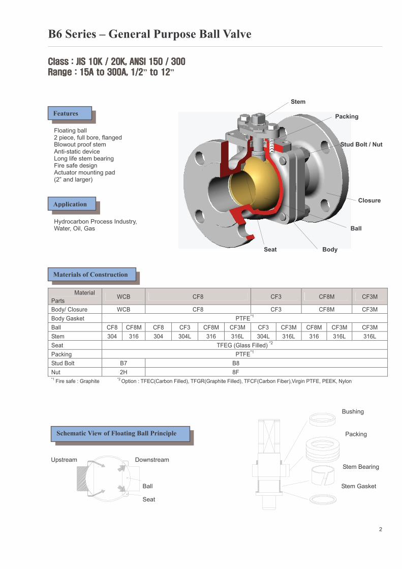
Stem Packing Floating ball 2 piece, full bore, flanged Blowout proof stem Stud Bolt / Nut Anti-static device Long life stem bearing Fire safe design Actuator mounting pad (2” and larger) Closure Hydrocarbon Process Industry, Water, Oil, Gas Ball Seat Body
Material
Parts WCB CF8 CF3 CF8M CF3M
Body/ Closure WCB CF8 CF3 CF8M CF3M
Body Gasket PTFE*1
Ball CF8 CF8M CF8 CF3 CF8M CF3M CF3 CF3M CF8M CF3M CF3M
Stem 304 316 304 304L 316 316L 304L 316L 316 316L 316L
Seat TFEG (Glass Filled) *2
Packing PTFE*1
Stud Bolt B7 B8
Nut 2H 8F *1
Fire safe : Graphite *2 Option : TFEC(Carbon Filled), TFGR(Graphite Filled), TFCF(Carbon Fiber),Virgin PTFE, PEEK, Nylon
Bushing Packing
Upstream Downstream Stem Bearing
Ball Stem Gasket
Seat
2
Features
Application
Materials of Construction
Schematic View of Floating Ball Principle
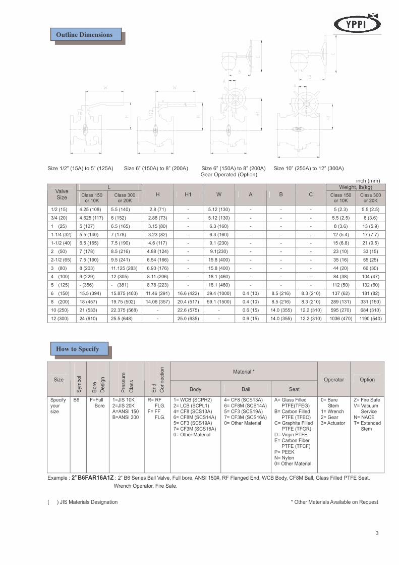
Size 1/2” (15A) to 5” (125A) Size 6” (150A) to 8” (200A) Size 6” (150A) to 8” (200A) Size 10” (250A) to 12” (300A) Gear Operated (Option) inch (mm)
L Weight, lb(kg) Valve Size
Class 150 or 10K
Class 300 or 20K
H H1 W A B C Class 150 or 10K
Class 300 or 20K
1/2 (15) 4.25 (108) 5.5 (140) 2.8 (71) - 5.12 (130) - - - 5 (2.3) 5.5 (2.5)
3/4 (20) 4.625 (117) 6 (152) 2.88 (73) - 5.12 (130) - - - 5.5 (2.5) 8 (3.6)
1 (25) 5 (127) 6.5 (165) 3.15 (80) - 6.3 (160) - - - 8 (3.6) 13 (5.9)
1-1/4 (32) 5.5 (140) 7 (178) 3.23 (82) - 6.3 (160) - - - 12 (5.4) 17 (7.7)
1-1/2 (40) 6.5 (165) 7.5 (190) 4.6 (117) - 9.1 (230) - - - 15 (6.8) 21 (9.5)
2 (50) 7 (178) 8.5 (216) 4.88 (124) - 9.1(230) - - - 23 (10) 33 (15)
2-1/2 (65) 7.5 (190) 9.5 (241) 6.54 (166) - 15.8 (400) - - - 35 (16) 55 (25)
3 (80) 8 (203) 11.125 (283) 6.93 (176) - 15.8 (400) - - - 44 (20) 66 (30)
4 (100) 9 (229) 12 (305) 8.11 (206) - 18.1 (460) - - - 84 (38) 104 (47)
5 (125) - (356) - (381) 8.78 (223) - 18.1 (460) - - - 112 (50) 132 (60)
6 (150) 15.5 (394) 15.875 (403) 11.46 (291) 16.6 (422) 39.4 (1000) 0.4 (10) 8.5 (216) 8.3 (210) 137 (62) 181 (82)
8 (200) 18 (457) 19.75 (502) 14.06 (357) 20.4 (517) 59.1 (1500) 0.4 (10) 8.5 (216) 8.3 (210) 289 (131) 331 (150)
10 (250) 21 (533) 22.375 (568) - 22.6 (575) - 0.6 (15) 14.0 (355) 12.2 (310) 595 (270) 684 (310)
12 (300) 24 (610) 25.5 (648) - 25.0 (635) - 0.6 (15) 14.0 (355) 12.2 (310) 1036 (470) 1190 (540)
Material *
Size
Symbol
Bore
Design
Pressu
re
Class
End
Connection
Body Ball Seat
Operator Option
Specify your size
B6 F=Full Bore
1=JIS 10K 2=JIS 20K A=ANSI 150 B=ANSI 300
R= RF FLG. F= FF FLG.
1= WCB (SCPH2) 2= LCB (SCPL1) 4= CF8 (SCS13A) 6= CF8M (SCS14A) 5= CF3 (SCS19A) 7= CF3M (SCS16A) 0= Other Material
4= CF8 (SCS13A) 6= CF8M (SCS14A) 5= CF3 (SCS19A) 7= CF3M (SCS16A) 0= Other Material
A= Glass Filled PTFE(TFEG) B= Carbon Filled PTFE (TFEC) C= Graphite Filled PTFE (TFGR) D= Virgin PTFE E= Carbon Fiber PTFE (TFCF) P= PEEK N= Nylon 0= Other Material
0= Bare Stem 1= Wrench 2= Gear 3= Actuator
Z= Fire Safe V= Vacuum Service N= NACE T= Extended Stem
Example : 2”B6FAR16A1Z : 2” B6 Series Ball Valve, Full bore, ANSI 150#, RF Flanged End, WCB Body, CF8M Ball, Glass Filled PTFE Seat,
Wrench Operator, Fire Safe.
( ) JIS Materials Designation * Other Materials Available on Request
3
How to Specify
Outline Dimensions
B7 Series – General Purpose Ball Valve
(Investment Casting)
Class : JIS 10K, ANSI 150Class : JIS 10K, ANSI 150Class : JIS 10K, ANSI 150Class : JIS 10K, ANSI 150
Range : 15A to 50A, 1/2Range : 15A to 50A, 1/2Range : 15A to 50A, 1/2Range : 15A to 50A, 1/2” to 2 to 2 to 2 to 2” Stem
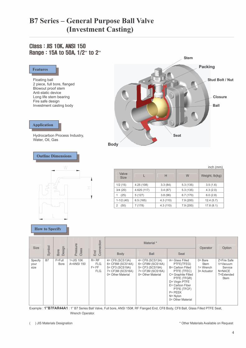
Packing Floating ball Stud Bolt / Nut 2 piece, full bore, flanged Blowout proof stem Anti-static device Long life stem bearing Closure Fire safe design Investment casting body Ball Hydrocarbon Process Industry, Seat Water, Oil, Gas
Body
inch (mm)
Valve Size
L H W Weight, lb(kg)
1/2 (15) 4.25 (108) 3.3 (84) 5.3 (135) 3.5 (1.6)
3/4 (20) 4.625 (117) 3.4 (87) 5.3 (135) 4.3 (2.0)
1 (25) 5 (127) 3.8 (96) 6.7 (170) 6.0 (2.8)
1-1/2 (40) 6.5 (165) 4.3 (110) 7.9 (200) 12.4 (5.7)
2 (50) 7 (178) 4.3 (110) 7.9 (200) 17.8 (8.1)
Material *
Size
Symbol
Bore
Design
Pressu
re
Class
End
Connection
Body Ball Seat
Operator Option
Specify your size
B7 F=Full Bore
1=JIS 10K A=ANSI 150
R= RF FLG. F= FF FLG.
4= CF8 (SCS13A) 6= CF8M (SCS14A) 5= CF3 (SCS19A) 7= CF3M (SCS16A) 0= Other Material
4= CF8 (SCS13A) 6= CF8M (SCS14A) 5= CF3 (SCS19A) 7= CF3M (SCS16A) 0= Other Material
A= Glass Filled PTFE(TFEG) B= Carbon Filled PTFE (TFEC) C= Graphite Filled PTFE (TFGR) D= Virgin PTFE E= Carbon Fiber PTFE (TFCF) P= PEEK N= Nylon 0= Other Material
0= Bare Stem 1= Wrench 3= Actuator
Z=Fire Safe V=Vacuum Service N=NACE T=Extended Stem
Example : 1”B7FAR44A1 : 1” B7 Series Ball Valve, Full bore, ANSI 150#, RF Flanged End, CF8 Body, CF8 Ball, Glass Filled PTFE Seat,
Wrench Operator.
( ) JIS Materials Designation * Other Materials Available on Request
4
Features
Application
How to Specify
Outline Dimensions
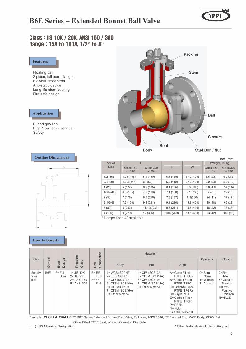
B6E Series – Extended Bonnet Ball Valve
Class : JIS 10K / 20K, ANSI 150 / 300Class : JIS 10K / 20K, ANSI 150 / 300Class : JIS 10K / 20K, ANSI 150 / 300Class : JIS 10K / 20K, ANSI 150 / 300
Range : 15A to 100A, 1Range : 15A to 100A, 1Range : 15A to 100A, 1Range : 15A to 100A, 1/2/2/2/2” to 4 to 4 to 4 to 4” Packing
Floating ball Stem 2 piece, full bore, flanged Blowout proof stem Anti-static device Long life stem bearing Fire safe design Ball Buried gas line High / low temp. service Safety Closure
Seat Body Stud Bolt / Nut
inch (mm)
L Weight, lb(kg) Valve Size Class 150
or 10K Class 300 or 20K
H W Class 150 or 10K
Class 300 or 20K
1/2 (15) 4.25 (108) 5.5 (140) 5.4 (138) 5.12 (130) 5.5 (2.5) 6.2 (2.8)
3/4 (20) 4.625(117) 6 (152) 5.6 (142) 5.12 (130) 6.2 (2.8) 8.8 (4.0)
1 (25) 5 (127) 6.5 (165) 6.1 (155) 6.3 (160) 8.8 (4.0) 14 (6.5)
1-1/2(40) 6.5 (165) 7.5 (190) 7.1 (180) 9.1 (230) 17 (7.5) 22 (10)
2 (50) 7 (178) 8.5 (216) 7.3 (187) 9.1(230) 24 (11) 37 (17)
2-1/2(65) 7.5 (190) 9.5 (241) 9.1 (230) 15.8 (400) 40 (18) 62 (28)
3 (80) 8 (203) 11.125(283) 9.5 (241) 15.8 (400) 48 (22) 73 (33)
4 (100) 9 (229) 12 (305) 10.6 (269) 18.1 (460) 93 (42) 115 (52)
* Larger than 4” available
Material *
Size
Symbol
Bore
Design
Pressu
re
Class
End
Connection
Body Ball Seat
Operator Option
Specify your size
B6E
F= Full Bore
1= JIS 10K 2= JIS 20K A= ANSI 150 B= ANSI 300
R= RF FLG. F= FF
FLG.
1= WCB (SCPH2) 2= LCB (SCPL1) 4= CF8 (SCS13A) 6= CF8M (SCS14A) 5= CF3 (SCS19A) 7= CF3M (SCS16A) 0= Other Material
4= CF8 (SCS13A) 6= CF8M (SCS14A) 5= CF3 (SCS19A) 7= CF3M (SCS16A) 0= Other Material
A= Glass Filled PTFE (TFEG) B= Carbon Filled PTFE (TFEC) C= Graphite Filled PTFE (TFGR) D= Virgin PTFE E= Carbon Fiber PTFE (TFCF) P= PEEK N= Nylon 0= Other Material
0= Bare Stem 1= Wrench 3= Actuator
Z=Fire Safe V=Vacuum Service L=Low- Fugitive Emission N=NACE
Example : 2B6EFAR16A1Z : 2” B6E Series Extended Bonnet Ball Valve, Full bore, ANSI 150#, RF Flanged End, WCB Body, CF8M Ball,
Glass Filled PTFE Seat, Wrench Operator, Fire Safe.
( ) : JIS Materials Designation * Other Materials Available on Request
5
Features
Application
How to Specify
Outline Dimensions
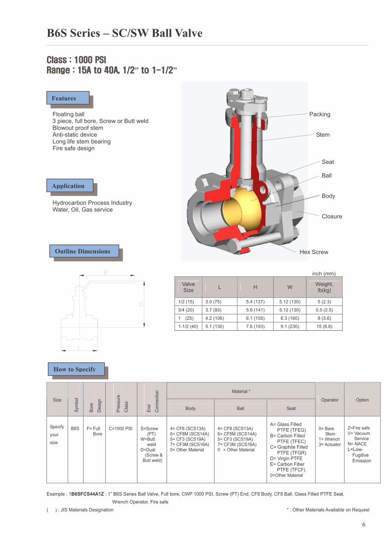
B6S Series – SC/SW Ball Valve
Class : 1000 PSIClass : 1000 PSIClass : 1000 PSIClass : 1000 PSI
Range : 15A to 40A, 1/2Range : 15A to 40A, 1/2Range : 15A to 40A, 1/2Range : 15A to 40A, 1/2” to 1 to 1 to 1 to 1----1/21/21/21/2” Floating ball Packing
3 piece, full bore, Screw or Butt weld Blowout proof stem Anti-static device Stem Long life stem bearing Fire safe design Seat Ball Body Hydrocarbon Process Industry Water, Oil, Gas service Closure
Hex Screw
inch (mm)
Valve Size
L H W Weight, lb(kg)
1/2 (15) 3.0 (75) 5.4 (137) 5.12 (130) 5 (2.3)
3/4 (20) 3.7 (93) 5.6 (141) 5.12 (130) 5.5 (2.5)
1 (25) 4.2 (106) 6.1 (155) 6.3 (160) 8 (3.6)
1-1/2 (40) 5.1 (130) 7.6 (193) 9.1 (230) 15 (6.8)
Material *
Size
Symbol
Bore
Design
Pressure
Class
End
Connection
Body Ball Seat
Operator Option
Specify
your
size
B6S
F= Full Bore
C=1000 PSI
S=Screw (PT) W=Butt weld D=Dual (Screw &
Butt weld)
4= CF8 (SCS13A) 6= CF8M (SCS14A) 5= CF3 (SCS19A) 7= CF3M (SCS16A) 0= Other Material
4= CF8 (SCS13A) 6= CF8M (SCS14A) 5= CF3 (SCS19A) 7= CF3M (SCS16A) 0 = Other Material
A= Glass Filled PTFE (TFEG) B= Carbon Filled PTFE (TFEC) C= Graphite Filled PTFE (TFGR) D= Virgin PTFE E= Carbon Fiber
PTFE (TFCF) 0=Other Material
0= Bare Stem 1= Wrench 3= Actuator
Z=Fire safe V= Vacuum Service N= NACE
L=Low- Fugitive Emission
Example : 1B6SFCS44A1Z : 1” B6S Series Ball Valve, Full bore, CWP 1000 PSI, Screw (PT) End, CF8 Body, CF8 Ball, Glass Filled PTFE Seat,
Wrench Operator, Fire safe
( ) : JIS Materials Designation * : Other Materials Available on Request
6
Features
Application
How to Specify
Outline Dimensions
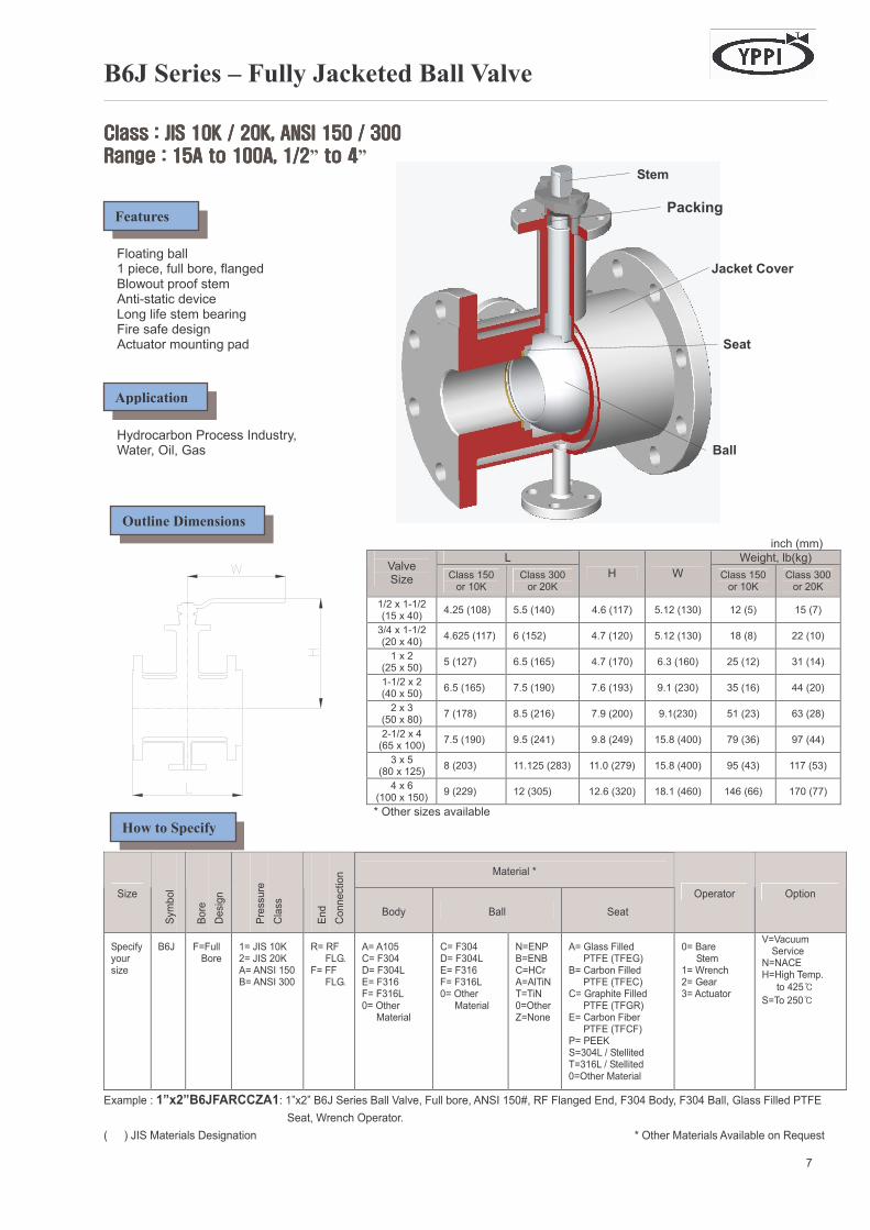
B6J Series – Fully Jacketed Ball Valve
Class : JIS 10K / 20K, ANSI 150 / 300Class : JIS 10K / 20K, ANSI 150 / 300Class : JIS 10K / 20K, ANSI 150 / 300Class : JIS 10K / 20K, ANSI 150 / 300
Range : 15A to 100A, 1/2Range : 15A to 100A, 1/2Range : 15A to 100A, 1/2Range : 15A to 100A, 1/2” to 4 to 4 to 4 to 4” Stem
Packing Floating ball 1 piece, full bore, flanged Jacket Cover Blowout proof stem Anti-static device Long life stem bearing Fire safe design Actuator mounting pad Seat Hydrocarbon Process Industry, Water, Oil, Gas Ball
inch (mm)
L Weight, lb(kg)
Valve Size Class 150
or 10K Class 300 or 20K
H W Class 150 or 10K
Class 300 or 20K
1/2 x 1-1/2 (15 x 40)
4.25 (108) 5.5 (140) 4.6 (117) 5.12 (130) 12 (5) 15 (7)
3/4 x 1-1/2 (20 x 40)
4.625 (117) 6 (152) 4.7 (120) 5.12 (130) 18 (8) 22 (10)
1 x 2 (25 x 50)
5 (127) 6.5 (165) 4.7 (170) 6.3 (160) 25 (12) 31 (14)
1-1/2 x 2 (40 x 50)
6.5 (165) 7.5 (190) 7.6 (193) 9.1 (230) 35 (16) 44 (20)
2 x 3 (50 x 80)
7 (178) 8.5 (216) 7.9 (200) 9.1(230) 51 (23) 63 (28)
2-1/2 x 4 (65 x 100)
7.5 (190) 9.5 (241) 9.8 (249) 15.8 (400) 79 (36) 97 (44)
3 x 5 (80 x 125)
8 (203) 11.125 (283) 11.0 (279) 15.8 (400) 95 (43) 117 (53)
4 x 6 (100 x 150)
9 (229) 12 (305) 12.6 (320) 18.1 (460) 146 (66) 170 (77)
* Other sizes available
Material *
Size
Symbol
Bore
Design
Pressure
Class
End
Connection
Body Ball Seat
Operator Option
Specify your size
B6J
F=Full Bore
1= JIS 10K 2= JIS 20K A= ANSI 150 B= ANSI 300
R= RF FLG.
F= FF FLG.
A= A105 C= F304 D= F304L E= F316 F= F316L 0= Other Material
C= F304 D= F304L E= F316 F= F316L 0= Other Material
N=ENP B=ENB C=HCr A=AlTiN T=TiN 0=Other Z=None
A= Glass Filled PTFE (TFEG) B= Carbon Filled PTFE (TFEC) C= Graphite Filled PTFE (TFGR) E= Carbon Fiber PTFE (TFCF) P= PEEK S=304L / Stellited T=316L / Stellited 0=Other Material
0= Bare Stem 1= Wrench 2= Gear 3= Actuator
V=Vacuum Service N=NACE H=High Temp.
to 425℃
S=To 250℃
Example : 1”x2”B6JFARCCZA1: 1”x2” B6J Series Ball Valve, Full bore, ANSI 150#, RF Flanged End, F304 Body, F304 Ball, Glass Filled PTFE
Seat, Wrench Operator.
( ) JIS Materials Designation * Other Materials Available on Request
7
Features
Application
How to Specify
Outline Dimensions
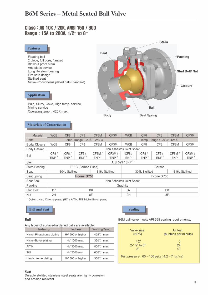
B6M Series – Metal Seated Ball Valve
Class : JIS 10K / 20K, ANSI 150 / 300Class : JIS 10K / 20K, ANSI 150 / 300Class : JIS 10K / 20K, ANSI 150 / 300Class : JIS 10K / 20K, ANSI 150 / 300
Range : 15A to 200A, 1/2Range : 15A to 200A, 1/2Range : 15A to 200A, 1/2Range : 15A to 200A, 1/2” to 8 to 8 to 8 to 8” Stem Seat Floating ball Packing 2 piece, full bore, flanged
Blowout proof stem Anti-static device Long life stem bearing Stud Bolt/ Nut Fire safe design Stellited seat Nickel-Phosphorus plated ball (Standard) Closure Pulp, Slurry, Coke, High temp. service, Mining service Ball
Operating temp. : 425℃max.
Body Seat Spring
Material WCB CF8 CF3 CF8M CF3M WCB CF8 CF3 CF8M CF3M
Parts Temp. Range : -29℃~ 250℃ Temp. Range : -29℃~ 425℃
Body/ Closure WCB CF8 CF3 CF8M CF3M WCB CF8 CF3 CF8M CF3M
Body Gasket Non Asbestos Joint Sheet
Ball CF8 /
ENP*1
CF8 /
ENP*1
CF3 /
ENP*1
CF8M /
ENP*1
CF3M /
ENP*1
CF8 /
ENP*1
CF8 /
ENP*1
CF3 /
ENP*1
CF8M /
ENP*1
CF3M /
ENP*1
Stem AISI 329 / ENP*1
Stem-Bearing TFEC (Carbon Filled) Carbon
Seat 304L Stellited 316L Stellited 304L Stellited 316L Stellited
Seat Spring Inconel X750 Inconel X750
Seat Seal Non Asbestos Joint Sheet
Packing Graphite
Stud Bolt B7 B8 B7 B8
Nut 2H 8F 2H 8F *1 Option : Hard Chrome plated (HCr), AlTiN, TiN, Nickel-Boron plated
Ball B6M ball valve meets API 598 sealing requirements.
Any types of surface-hardened balls are available.
Hardening Hardness Working Temp.
Nickel-Phosphorus plating HV 600 or higher 425℃ max.
Nickel-Boron plating HV 1000 max. 350℃ max.
AlTiN HV 3000 max. 800℃ max.
TiN HV 2500 max. 600℃ max.
Hard chrome plating HV 800 or higher 350℃ max.
Seat Durable stellited stainless steel seats are highly corrosion and erosion resistant.
8
Features
Application
Materials of Construction
Ball and Seat Sealing
Valve size Air test (NPS) (bubbles per minute)
≤2” 0
2-1/2” to 6” 24 8” 40
Test pressure : 60∼100 psig ( 4.2∼7 ㎏/㎠)
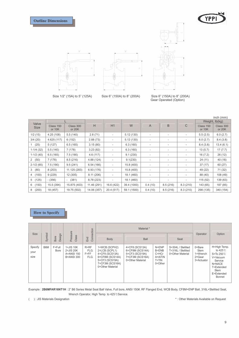
Size 1/2” (15A) to 5” (125A) Size 6” (150A) to 8” (200A) Size 6” (150A) to 8” (200A) Gear Operated (Option)
inch (mm)
L Weight, lb(kg) Valve Size
Class 150 or 10K
Class 300 or 20K
H H1 W A B C Class 150 or 10K
Class 300 or 20K
1/2 (15) 4.25 (108) 5.5 (140) 2.8 (71) - 5.12 (130) - - - 5.5 (2.5) 6.0 (2.7)
3/4 (20) 4.625 (117) 6 (152) 2.88 (73) - 5.12 (130) - - - 6.0 (2.7) 8.4 (3.8)
1 (25) 5 (127) 6.5 (165) 3.15 (80) - 6.3 (160) - - - 8.4 (3.8) 13.4 (6.1)
1-1/4 (32) 5.5 (140) 7 (178) 3.23 (82) - 6.3 (160) - - - 13 (5.7) 17 (7.7)
1-1/2 (40) 6.5 (165) 7.5 (190) 4.6 (117) - 9.1 (230) - - - 16 (7.2) 26 (12)
2 (50) 7 (178) 8.5 (216) 4.88 (124) - 9.1(230) - - - 24 (11) 40 (18)
2-1/2 (65) 7.5 (190) 9.5 (241) 6.54 (166) - 15.8 (400) - - - 37 (17) 60 (27)
3 (80) 8 (203) 11.125 (283) 6.93 (176) - 15.8 (400) - - - 49 (22) 71 (32)
4 (100) 9 (229) 12 (305) 8.11 (206) - 18.1 (460) - - - 88 (40) 108 (49)
5 (125) - (356) - (381) 8,78 (223) - 18.1 (460) - - - 115 (52) 139 (63)
6 (150) 15.5 (394) 15.875 (403) 11.46 (291) 16.6 (422) 39.4 (1000) 0.4 (10) 8.5 (216) 8.3 (210) 143 (65) 187 (85)
8 (200) 18 (457) 19.75 (502) 14.06 (357) 20.4 (517) 59.1 (1500) 0.4 (10) 8.5 (216) 8.3 (210) 298 (135) 340 (154)
Material *
Size
Symbol
Bore
Design
Pressure
Class
End
Connection
Body Ball Seat
Operator Option
Specify
your
size
B6M
F=Full Bore
1=JIS 10K 2=JIS 20K A=ANSI 150 B=ANSI 300
R=RF FLG. F=FF FLG.
1=WCB (SCPH2) 2=LCB (SCPL1) 4=CF8 (SCS13A) 6=CF8M (SCS14A) 5=CF3 (SCS19A) 7=CF3M (SCS16A) 0=Other Material
4=CF8 (SCS13A) 6=CF8M (SCS14A) 5=CF3 (SCS19A) 7=CF3M (SCS16A) 0=Other Material
N=ENP B=ENB C=HCr A=AlTiN T=TiN 0=Other
S=304L / Stellited T=316L / Stellited 0=Other Material
0=Bare Stem 1=Wrench 2=Gear 3=Actuator
H=High Temp.
to 425℃
S=To 250℃
V=Vacuum Service N=NACE T=Extended Stem E=Extended Bonnet
Example : 2B6MFAR16NT1H : 2” B6 Series Metal Seat Ball Valve, Full bore, ANSI 150#, RF Flanged End, WCB Body, CF8M+ENP Ball, 316L+Stellited Seat,
Wrench Operator, High Temp. to 425℃Service.
( ) : JIS Materials Designation * : Other Materials Available on Request
9
How to Specify
Outline Dimensions
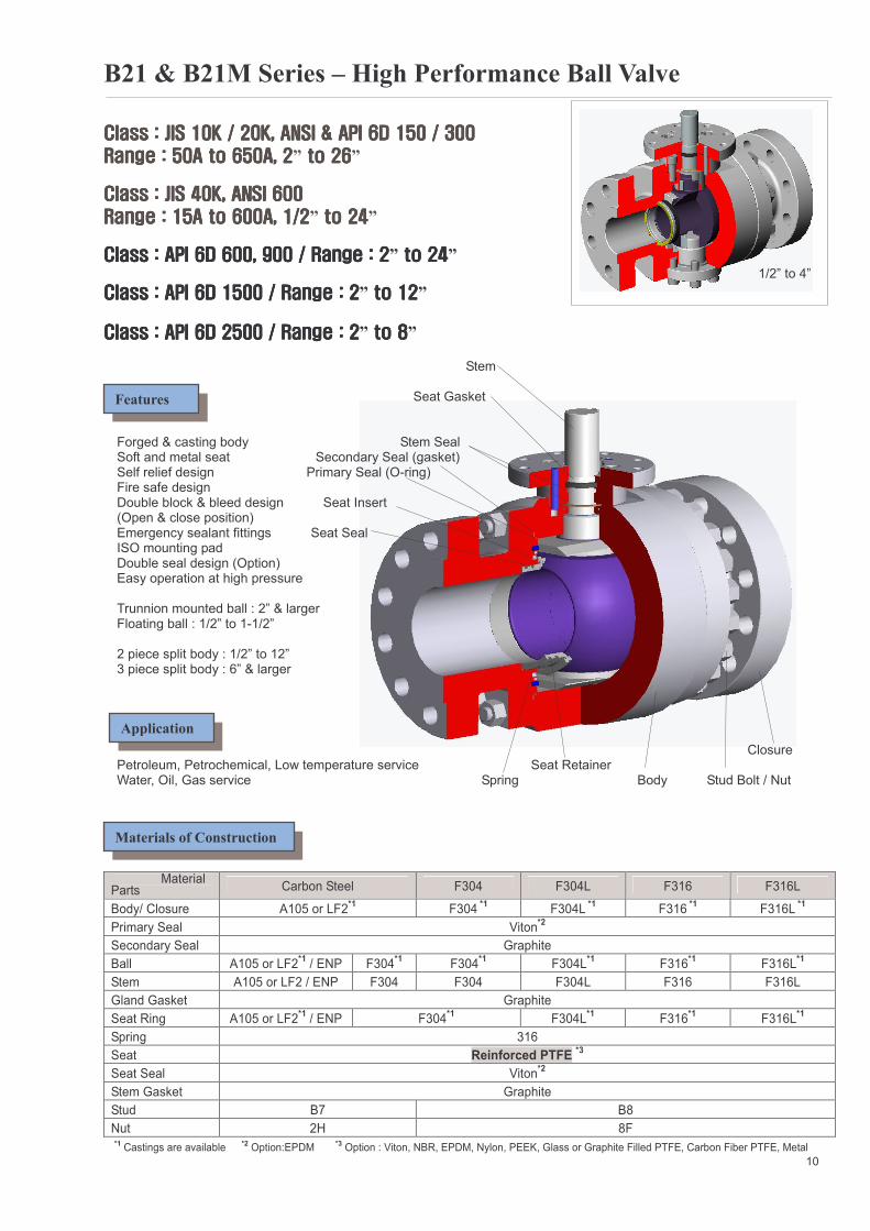
B21 & B21M Series – High Performance Ball Valve
Class : JIS 10K / 20K, ANSI & API 6D 150 / 300Class : JIS 10K / 20K, ANSI & API 6D 150 / 300Class : JIS 10K / 20K, ANSI & API 6D 150 / 300Class : JIS 10K / 20K, ANSI & API 6D 150 / 300
Range : 50A to 6Range : 50A to 6Range : 50A to 6Range : 50A to 650A, 250A, 250A, 250A, 2” to 26 to 26 to 26 to 26”
Class : JIS 40K, ANSI 600Class : JIS 40K, ANSI 600Class : JIS 40K, ANSI 600Class : JIS 40K, ANSI 600
Range : 15A to 600A, 1/2Range : 15A to 600A, 1/2Range : 15A to 600A, 1/2Range : 15A to 600A, 1/2” to 24 to 24 to 24 to 24”
Class : API 6D 600, 900 / Range : 2Class : API 6D 600, 900 / Range : 2Class : API 6D 600, 900 / Range : 2Class : API 6D 600, 900 / Range : 2” to 24 to 24 to 24 to 24” 1/2” to 4”
Class : API 6D 1500 / Range : 2Class : API 6D 1500 / Range : 2Class : API 6D 1500 / Range : 2Class : API 6D 1500 / Range : 2” to 12 to 12 to 12 to 12”
Class : API 6D 2500 / Range : 2Class : API 6D 2500 / Range : 2Class : API 6D 2500 / Range : 2Class : API 6D 2500 / Range : 2” to 8 to 8 to 8 to 8” Stem Seat Gasket Forged & casting body Stem Seal Soft and metal seat Secondary Seal (gasket) Self relief design Primary Seal (O-ring) Fire safe design Double block & bleed design Seat Insert (Open & close position) Emergency sealant fittings Seat Seal ISO mounting pad Double seal design (Option) Easy operation at high pressure Trunnion mounted ball : 2” & larger Floating ball : 1/2” to 1-1/2” 2 piece split body : 1/2” to 12” 3 piece split body : 6” & larger
Closure Petroleum, Petrochemical, Low temperature service Seat Retainer Water, Oil, Gas service Spring Body Stud Bolt / Nut
Material Parts Carbon Steel F304 F304L F316 F316L
Body/ Closure A105 or LF2*1 F304
*1 F304L
*1 F316
*1 F316L
*1
Primary Seal Viton*2
Secondary Seal Graphite
Ball A105 or LF2*1 / ENP F304
*1 F304
*1 F304L
*1 F316
*1 F316L
*1
Stem A105 or LF2 / ENP F304 F304 F304L F316 F316L
Gland Gasket Graphite
Seat Ring A105 or LF2*1 / ENP F304
*1 F304L
*1 F316
*1 F316L
*1
Spring 316
Seat Reinforced PTFE *3
Seat Seal Viton*2
Stem Gasket Graphite
Stud B7 B8
Nut 2H 8F
*1 Castings are available *2 Option:EPDM *3 Option : Viton, NBR, EPDM, Nylon, PEEK, Glass or Graphite Filled PTFE, Carbon Fiber PTFE, Metal
10
Features
Application
Materials of Construction
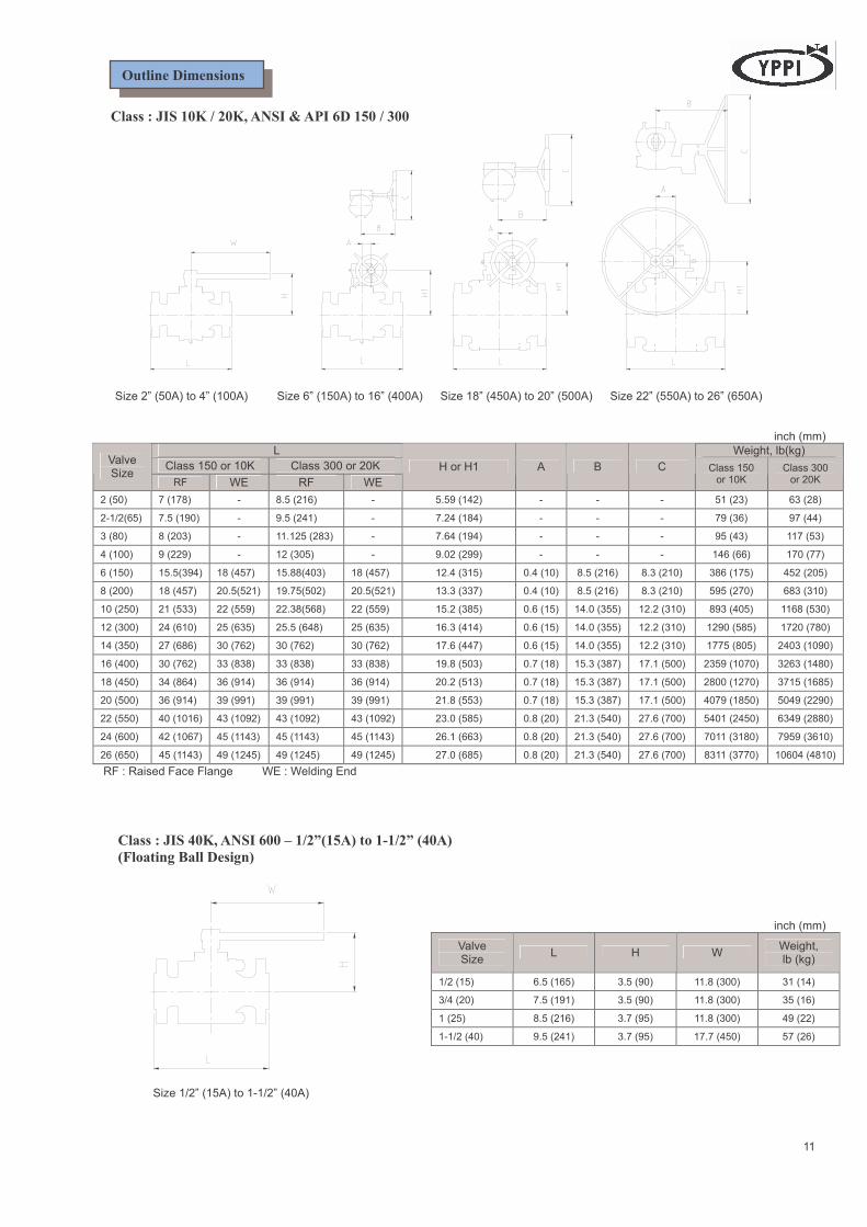
Class : JIS 10K / 20K, ANSI & API 6D 150 / 300
Size 2” (50A) to 4” (100A) Size 6” (150A) to 16” (400A) Size 18” (450A) to 20” (500A) Size 22” (550A) to 26” (650A) inch (mm)
L Weight, lb(kg)
Class 150 or 10K Class 300 or 20K Valve Size
RF WE RF WE
H or H1 A B C Class 150 or 10K
Class 300 or 20K
2 (50) 7 (178) - 8.5 (216) - 5.59 (142) - - - 51 (23) 63 (28)
2-1/2(65) 7.5 (190) - 9.5 (241) - 7.24 (184) - - - 79 (36) 97 (44)
3 (80) 8 (203) - 11.125 (283) - 7.64 (194) - - - 95 (43) 117 (53)
4 (100) 9 (229) - 12 (305) - 9.02 (299) - - - 146 (66) 170 (77)
6 (150) 15.5(394) 18 (457) 15.88(403) 18 (457) 12.4 (315) 0.4 (10) 8.5 (216) 8.3 (210) 386 (175) 452 (205)
8 (200) 18 (457) 20.5(521) 19.75(502) 20.5(521) 13.3 (337) 0.4 (10) 8.5 (216) 8.3 (210) 595 (270) 683 (310)
10 (250) 21 (533) 22 (559) 22.38(568) 22 (559) 15.2 (385) 0.6 (15) 14.0 (355) 12.2 (310) 893 (405) 1168 (530)
12 (300) 24 (610) 25 (635) 25.5 (648) 25 (635) 16.3 (414) 0.6 (15) 14.0 (355) 12.2 (310) 1290 (585) 1720 (780)
14 (350) 27 (686) 30 (762) 30 (762) 30 (762) 17.6 (447) 0.6 (15) 14.0 (355) 12.2 (310) 1775 (805) 2403 (1090)
16 (400) 30 (762) 33 (838) 33 (838) 33 (838) 19.8 (503) 0.7 (18) 15.3 (387) 17.1 (500) 2359 (1070) 3263 (1480)
18 (450) 34 (864) 36 (914) 36 (914) 36 (914) 20.2 (513) 0.7 (18) 15.3 (387) 17.1 (500) 2800 (1270) 3715 (1685)
20 (500) 36 (914) 39 (991) 39 (991) 39 (991) 21.8 (553) 0.7 (18) 15.3 (387) 17.1 (500) 4079 (1850) 5049 (2290)
22 (550) 40 (1016) 43 (1092) 43 (1092) 43 (1092) 23.0 (585) 0.8 (20) 21.3 (540) 27.6 (700) 5401 (2450) 6349 (2880)
24 (600) 42 (1067) 45 (1143) 45 (1143) 45 (1143) 26.1 (663) 0.8 (20) 21.3 (540) 27.6 (700) 7011 (3180) 7959 (3610)
26 (650) 45 (1143) 49 (1245) 49 (1245) 49 (1245) 27.0 (685) 0.8 (20) 21.3 (540) 27.6 (700) 8311 (3770) 10604 (4810)
RF : Raised Face Flange WE : Welding End
Class : JIS 40K, ANSI 600 – 1/2”(15A) to 1-1/2” (40A)
(Floating Ball Design) inch (mm)
Valve Size
L H W Weight, lb (kg)
1/2 (15) 6.5 (165) 3.5 (90) 11.8 (300) 31 (14)
3/4 (20) 7.5 (191) 3.5 (90) 11.8 (300) 35 (16)
1 (25) 8.5 (216) 3.7 (95) 11.8 (300) 49 (22)
1-1/2 (40) 9.5 (241) 3.7 (95) 17.7 (450) 57 (26)
Size 1/2” (15A) to 1-1/2” (40A)
11
Outline Dimensions
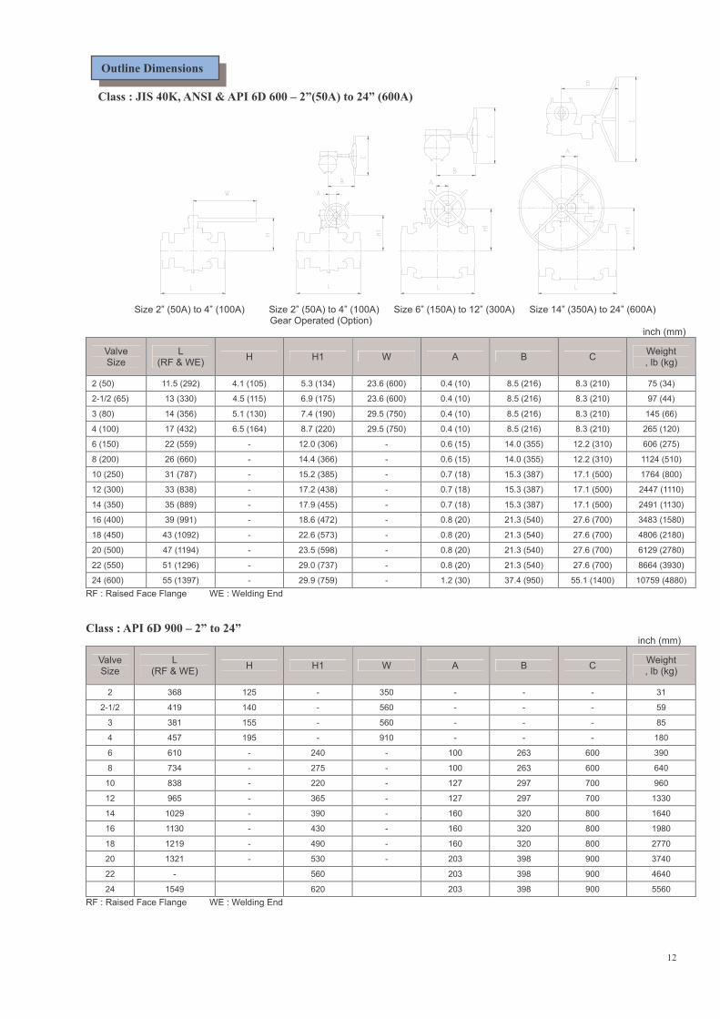
Class : JIS 40K, ANSI & API 6D 600 – 2”(50A) to 24” (600A) Size 2” (50A) to 4” (100A) Size 2” (50A) to 4” (100A) Size 6” (150A) to 12” (300A) Size 14” (350A) to 24” (600A) Gear Operated (Option) inch (mm)
Valve Size
L (RF & WE)
H H1 W A B C Weight , lb (kg)
2 (50) 11.5 (292) 4.1 (105) 5.3 (134) 23.6 (600) 0.4 (10) 8.5 (216) 8.3 (210) 75 (34)
2-1/2 (65) 13 (330) 4.5 (115) 6.9 (175) 23.6 (600) 0.4 (10) 8.5 (216) 8.3 (210) 97 (44)
3 (80) 14 (356) 5.1 (130) 7.4 (190) 29.5 (750) 0.4 (10) 8.5 (216) 8.3 (210) 145 (66)
4 (100) 17 (432) 6.5 (164) 8.7 (220) 29.5 (750) 0.4 (10) 8.5 (216) 8.3 (210) 265 (120)
6 (150) 22 (559) - 12.0 (306) - 0.6 (15) 14.0 (355) 12.2 (310) 606 (275)
8 (200) 26 (660) - 14.4 (366) - 0.6 (15) 14.0 (355) 12.2 (310) 1124 (510)
10 (250) 31 (787) - 15.2 (385) - 0.7 (18) 15.3 (387) 17.1 (500) 1764 (800)
12 (300) 33 (838) - 17.2 (438) - 0.7 (18) 15.3 (387) 17.1 (500) 2447 (1110)
14 (350) 35 (889) - 17.9 (455) - 0.7 (18) 15.3 (387) 17.1 (500) 2491 (1130)
16 (400) 39 (991) - 18.6 (472) - 0.8 (20) 21.3 (540) 27.6 (700) 3483 (1580)
18 (450) 43 (1092) - 22.6 (573) - 0.8 (20) 21.3 (540) 27.6 (700) 4806 (2180)
20 (500) 47 (1194) - 23.5 (598) - 0.8 (20) 21.3 (540) 27.6 (700) 6129 (2780)
22 (550) 51 (1296) - 29.0 (737) - 0.8 (20) 21.3 (540) 27.6 (700) 8664 (3930)
24 (600) 55 (1397) - 29.9 (759) - 1.2 (30) 37.4 (950) 55.1 (1400) 10759 (4880)
RF : Raised Face Flange WE : Welding End
Class : API 6D 900 – 2” to 24” inch (mm)
Valve Size
L (RF & WE)
H H1 W A B C Weight , lb (kg)
2 368 125 - 350 - - - 31
2-1/2 419 140 - 560 - - - 59
3 381 155 - 560 - - - 85
4 457 195 - 910 - - - 180
6 610 - 240 - 100 263 600 390
8 734 - 275 - 100 263 600 640
10 838 - 220 - 127 297 700 960
12 965 - 365 - 127 297 700 1330
14 1029 - 390 - 160 320 800 1640
16 1130 - 430 - 160 320 800 1980
18 1219 - 490 - 160 320 800 2770
20 1321 - 530 - 203 398 900 3740
22 - 560 203 398 900 4640
24 1549 620 203 398 900 5560
RF : Raised Face Flange WE : Welding End
12
Outline Dimensions
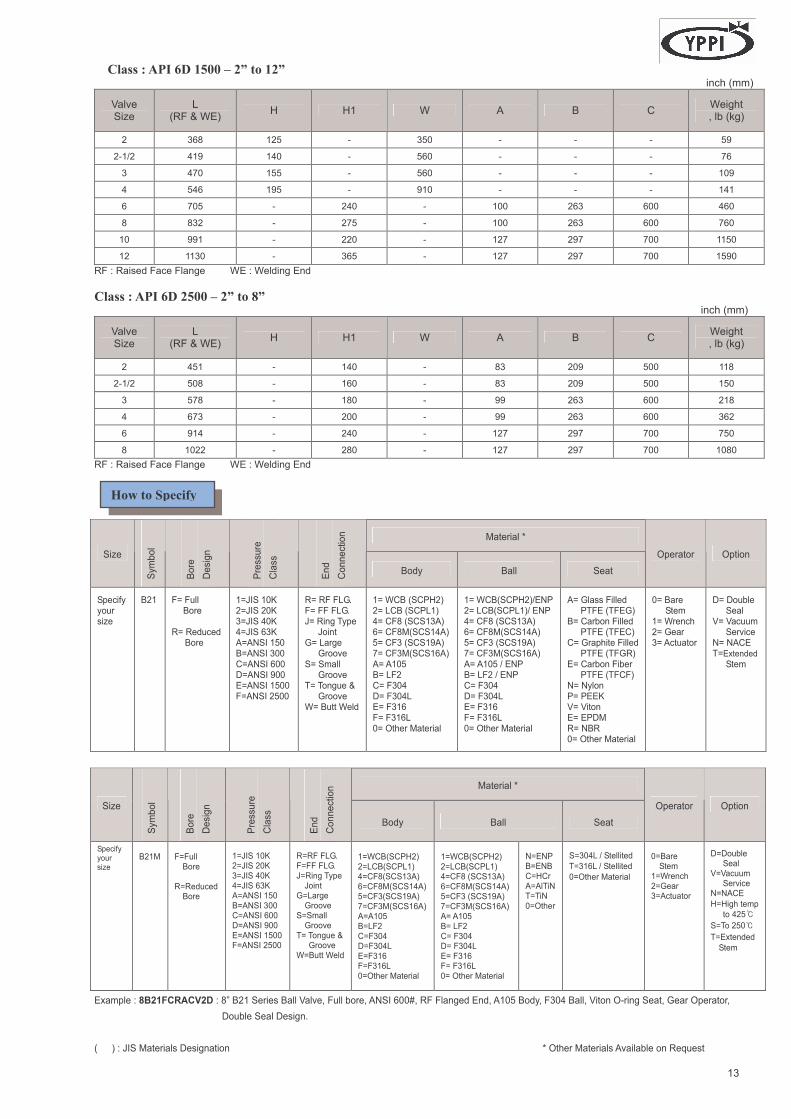
Class : API 6D 1500 – 2” to 12” inch (mm)
Valve Size
L (RF & WE)
H H1 W A B C Weight , lb (kg)
2 368 125 - 350 - - - 59
2-1/2 419 140 - 560 - - - 76
3 470 155 - 560 - - - 109
4 546 195 - 910 - - - 141
6 705 - 240 - 100 263 600 460
8 832 - 275 - 100 263 600 760
10 991 - 220 - 127 297 700 1150
12 1130 - 365 - 127 297 700 1590
RF : Raised Face Flange WE : Welding End
Class : API 6D 2500 – 2” to 8” inch (mm)
Valve Size
L (RF & WE)
H H1 W A B C Weight , lb (kg)
2 451 - 140 - 83 209 500 118
2-1/2 508 - 160 - 83 209 500 150
3 578 - 180 - 99 263 600 218
4 673 - 200 - 99 263 600 362
6 914 - 240 - 127 297 700 750
8 1022 - 280 - 127 297 700 1080
RF : Raised Face Flange WE : Welding End
Material *
Size
Symbol
Bore
Design
Pressure
Class
End
Connection
Body Ball Seat
Operator Option
Specify your size
B21
F= Full Bore R= Reduced
Bore
1=JIS 10K 2=JIS 20K 3=JIS 40K 4=JIS 63K A=ANSI 150 B=ANSI 300 C=ANSI 600 D=ANSI 900 E=ANSI 1500 F=ANSI 2500
R= RF FLG. F= FF FLG. J= Ring Type Joint G= Large Groove S= Small Groove T= Tongue & Groove W= Butt Weld
1= WCB (SCPH2) 2= LCB (SCPL1) 4= CF8 (SCS13A) 6= CF8M(SCS14A) 5= CF3 (SCS19A) 7= CF3M(SCS16A) A= A105 B= LF2 C= F304 D= F304L E= F316 F= F316L 0= Other Material
1= WCB(SCPH2)/ENP 2= LCB(SCPL1)/ ENP 4= CF8 (SCS13A) 6= CF8M(SCS14A) 5= CF3 (SCS19A) 7= CF3M(SCS16A) A= A105 / ENP B= LF2 / ENP C= F304 D= F304L E= F316 F= F316L 0= Other Material
A= Glass Filled PTFE (TFEG) B= Carbon Filled PTFE (TFEC) C= Graphite Filled PTFE (TFGR) E= Carbon Fiber PTFE (TFCF) N= Nylon P= PEEK V= Viton E= EPDM R= NBR 0= Other Material
0= Bare Stem 1= Wrench 2= Gear 3= Actuator
D= Double Seal V= Vacuum Service N= NACE T=Extended Stem
Material *
Size
Symbol
Bore
Design
Pressure
Class
End
Connection
Body Ball Seat
Operator Option
Specify your size
B21M
F=Full Bore R=Reduced
Bore
1=JIS 10K 2=JIS 20K 3=JIS 40K 4=JIS 63K A=ANSI 150 B=ANSI 300 C=ANSI 600 D=ANSI 900 E=ANSI 1500 F=ANSI 2500
R=RF FLG. F=FF FLG. J=Ring Type Joint G=Large Groove S=Small Groove T= Tongue & Groove W=Butt Weld
1=WCB(SCPH2) 2=LCB(SCPL1) 4=CF8(SCS13A) 6=CF8M(SCS14A) 5=CF3(SCS19A) 7=CF3M(SCS16A) A=A105 B=LF2 C=F304 D=F304L E=F316 F=F316L 0=Other Material
1=WCB(SCPH2) 2=LCB(SCPL1) 4=CF8 (SCS13A) 6=CF8M(SCS14A) 5=CF3 (SCS19A) 7=CF3M(SCS16A) A= A105 B= LF2 C= F304 D= F304L E= F316 F= F316L 0= Other Material
N=ENP B=ENB C=HCr A=AlTiN T=TiN 0=Other
S=304L / Stellited
T=316L / Stellited
0=Other Material
0=Bare Stem 1=Wrench 2=Gear 3=Actuator
D=Double Seal V=Vacuum Service N=NACE
H=High temp
to 425℃
S=To 250℃
T=Extended
Stem
Example : 8B21FCRACV2D : 8” B21 Series Ball Valve, Full bore, ANSI 600#, RF Flanged End, A105 Body, F304 Ball, Viton O-ring Seat, Gear Operator,
Double Seal Design.
( ) : JIS Materials Designation * Other Materials Available on Request 13
How to Specify
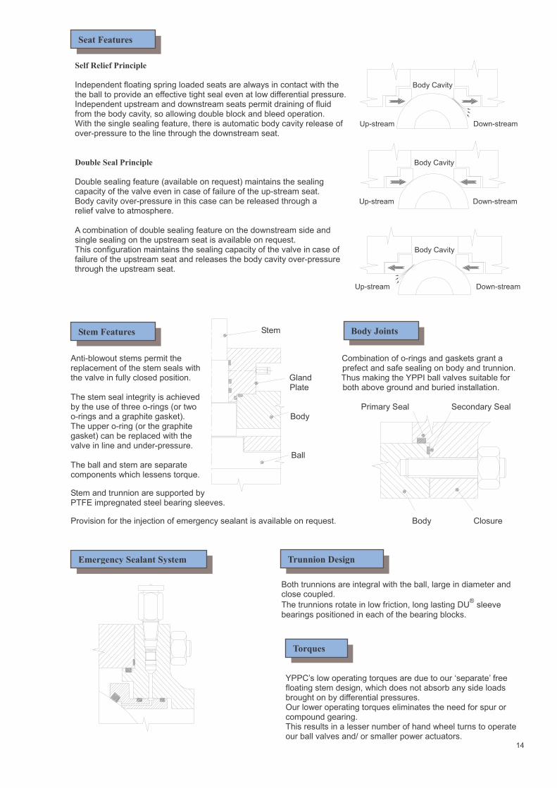
Self Relief Principle
Independent floating spring loaded seats are always in contact with the Body Cavity the ball to provide an effective tight seal even at low differential pressure. Independent upstream and downstream seats permit draining of fluid from the body cavity, so allowing double block and bleed operation. With the single sealing feature, there is automatic body cavity release of Up-stream Down-stream over-pressure to the line through the downstream seat.
Double Seal Principle Body Cavity
Double sealing feature (available on request) maintains the sealing capacity of the valve even in case of failure of the up-stream seat. Body cavity over-pressure in this case can be released through a Up-stream Down-stream
relief valve to atmosphere. A combination of double sealing feature on the downstream side and single sealing on the upstream seat is available on request. This configuration maintains the sealing capacity of the valve in case of Body Cavity failure of the upstream seat and releases the body cavity over-pressure through the upstream seat.
Up-stream Down-stream
Stem
Anti-blowout stems permit the Combination of o-rings and gaskets grant a replacement of the stem seals with prefect and safe sealing on body and trunnion. the valve in fully closed position. Gland Thus making the YPPI ball valves suitable for
Plate both above ground and buried installation. The stem seal integrity is achieved by the use of three o-rings (or two Primary Seal Secondary Seal o-rings and a graphite gasket). Body The upper o-ring (or the graphite gasket) can be replaced with the valve in line and under-pressure. Ball The ball and stem are separate components which lessens torque.
Stem and trunnion are supported by PTFE impregnated steel bearing sleeves.
Provision for the injection of emergency sealant is available on request. Body Closure
Both trunnions are integral with the ball, large in diameter and close coupled.
The trunnions rotate in low friction, long lasting DU® sleeve
bearings positioned in each of the bearing blocks.
YPPC’s low operating torques are due to our ‘separate’ free floating stem design, which does not absorb any side loads brought on by differential pressures. Our lower operating torques eliminates the need for spur or compound gearing. This results in a lesser number of hand wheel turns to operate our ball valves and/ or smaller power actuators.
14
Seat Features
Stem Features Body Joints
Emergency Sealant System Trunnion Design
Torques
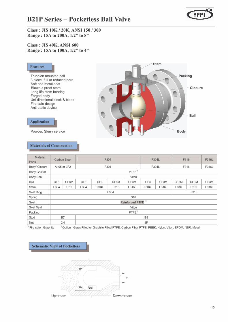
B21P Series – Pocketless Ball Valve
Class : JIS 10K / 20K, ANSI 150 / 300
Range : 15A to 200A, 1/2” to 8”
Class : JIS 40K, ANSI 600
Range : 15A to 100A, 1/2” to 4”
Stem Trunnion mounted ball Packing 3 piece, full or reduced bore Soft and metal seat
Blowout proof stem Closure Long life stem bearing Forged body Uni-directional block & bleed Fire safe design Anti-static device Ball Powder, Slurry service Body
Material
Parts Carbon Steel F304 F304L F316 F316L
Body/ Closure A105 or LF2 F304 F304L F316 F316L
Body Gasket PTFE*1
Body Seal Viton
Ball CF8 CF8M CF8 CF3 CF8M CF3M CF3 CF3M CF8M CF3M CF3M
Stem F304 F316 F304 F304L F316 F316L F304L F316L F316 F316L F316L
Seat Ring F304 F316
Spring 316
Seat Reinforced PTFE *2
Seat Seal Viton
Packing PTFE*1
Stud B7 B8
Nut 2H 8F *1 Fire safe : Graphite
*2 Option : Glass Filled or Graphite Filled PTFE, Carbon Fiber PTFE, PEEK, Nylon, Viton, EPDM, NBR, Metal
Ball Upstream Downstream
15
Features
Application
Materials of Construction
Schematic View of Pocketless

ANSI 150#,300#, JIS 10K,20K ANSI 150#,300#, JIS 10K,20K ANSI 600#, JIS 40K ANSI 600#, JIS 40K Size 1/2” (15A) to 5” (125A) Size 6” (150A) to 8” (200A) Size 1/2” (15A) to 4” (100A) Size 2” (50A) to 4” (100A) Gear Operated (Option)
Class : JIS 10K/ 20K, ANSI 150/ 300 inch (mm) L Weight, lb(kg)
Valve Size
Class 150 or 10K
Class 300 or 20K
H H1 W A B C Class 150 or 10K
Class 300 or 20K
1/2 (15) 4.25 (108) 5.5 (140) 2.8 (71) - 5.12 (130) - - - 5.7 (2.6) 6.2 (2.8)
3/4 (20) 4.625 (117) 6 (152) 2.88 (73) - 5.12 (130) - - - 6.3 (2.9) 10 (4.5)
1 (25) 5 (127) 6.5 (165) 3.15 (80) - 6.3 (160) - - - 11 (5.0) 15 (6.8)
1-1/2 (40) 6.5 (165) 7.5 (190) 4.6 (117) - 9.1 (230) - - - 24 (11) 29 (13)
2 (50) 7 (178) 8.5 (216) 4.88 (124) - 9.1(230) - - - 32 (15) 38 (17)
2-1/2 (65) 7.5 (190) 9.5 (241) 6.54 (166) - 15.8 (400) - - - 40 (18) 60 (27)
3 (80) 8 (203) 11.125 (283) 6.93 (176) - 15.8 (400) - - - 49 (22) 72 (33)
4 (100) 9 (229) 12 (305) 8.11 (206) - 18.1 (460) - - - 92 (42) 120 (54)
5 (125) - (356) - (381) 8.78 (223) - 18.1 (460) - - - 122 (55) 148 (67)
6 (150) 15.5 (394) 15.875 (403) - 16.6 (422) - 0.4 (10) 8.5 (216) 8.3 (211) 152 (69) 200 (91)
8 (200) 18 (457) 19.75 (502) - 20.4 (517) - 0.4 (10) 8.5 (216) 8.3 (211) 310 (141) 352 (160)
Class : JIS 40K, ANSI 600 inch (mm)
Valve Size
L H H1 W A B C Weight , lb (kg)
1/2 (15) 6.5 (165) 3.5 (90) - 11.8 (300) - - - 29 (13)
3/4 (20) 7.5 (191) 3.5 (90) - 11.8 (300) - - - 33 (15)
1 (25) 8.5 (216) 3.7 (95) - 11.8 (300) - - - 46 (21)
1-1/2 (40) 9.5 (241) 3.7 (95) - 17.7 (450) - - - 51 (23)
2 (50) 11.5 (292) 4.1 (105) 5.3 (134) 23.6 (600) 0.4 (10) 8.5 (216) 8.3 (210) 71 (32)
2-1/2 (65) 13 (330) 4.5 (115) 6.9 (175) 23.6 (600) 0.4 (10) 8.5 (216) 8.3 (210) 93 (42)
3 (80) 14 (356) 5.1 (130) 7.4 (190) 29.5 (750) 0.4 (10) 8.5 (216) 8.3 (210) 137 (62)
4 (100) 17 (432) 6.5 (164) 8.7 (220) 29.5 (750) 0.4 (10) 8.5 (216) 8.3 (210) 255 (116)
Material *
Size
Symbol
Bore
Design
Pressure
Class
End
Connection
Body Ball Seat
Operator Option
Specify your size
B21P
F= Full Bore R= Reduced Bore
1= JIS 10K 2= JIS 20K 3= JIS 40K A= ANSI 150 B= ANSI 300 C= ANSI 600
R= RF FLG. F= FF FLG. T= Ring Type Joint G= Large Groove S= Small Groove T= Tongue & Groove W= Butt Weld
A= A105 B= LF2 C= F304 D= F304L E= F316 F= F316L 0= Other Material
4= CF8 (SCS13A)
6= CF8M (SCS14A)
5= CF3 (SCS19A)
7= CF3M (SCS16A)
0= Other Material
N=ENP B=ENB C=HCr A=AlTiN T=TiN 0=Other Z=None
A=Glass Filled PTFE (TFEG) B=Carbon Filled PTFE (TFEC) C=Graphite Filled PTFE (TFGR) N=Nylon P=PEEK V=Viton E=EPDM R=NBR S=304L/ Stellited T=316L/ Stellited 0=Other Material
0= Bare Stem 1= Wrench 2= Gear 3= Actuator
Z= Fire Safe V= Vacuum Service N= NACE H=High temp
to 425℃
S=To 250℃
T=Extended Stem
Example : 4B21PFCRA6V1Z : 4” B21P Series Pocket-less Ball Valve, Full bore, ANSI 600#, RF Flanged End, A105 Body, CF8M Ball, Viton O ring Seat,
Wrench Operator, Fire Safe
( ) : JIS Materials Designation * Other Materials Available on Request
16
Outline Dimensions
How to Specify
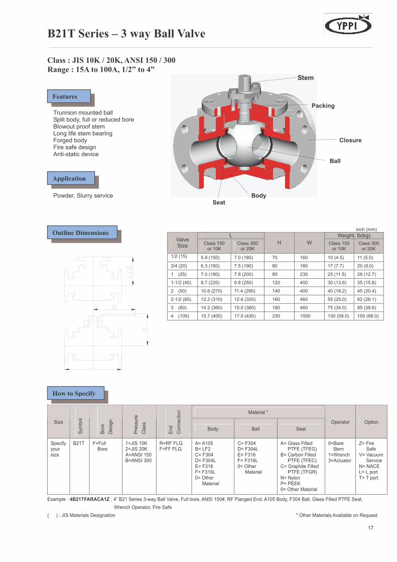
B21T Series – 3 way Ball Valve
Class : JIS 10K / 20K, ANSI 150 / 300
Range : 15A to 100A, 1/2” to 4” Stem Packing Trunnion mounted ball Split body, full or reduced bore Blowout proof stem Long life stem bearing Forged body Closure Fire safe design Anti-static device Ball Powder, Slurry service Body Seat inch (mm)
L Weight, lb(kg) Valve Size
Class 150 or 10K
Class 300 or 20K
H W Class 150 or 10K
Class 300 or 20K
1/2 (15) 5.9 (150) 7.0 (180) 70 160 10 (4.5) 11 (5.0)
3/4 (20) 6.3 (160) 7.5 (190) 80 160 17 (7.7) 20 (9.0)
1 (25) 7.0 (180) 7.8 (200) 85 230 25 (11.5) 28 (12.7)
1-1/2 (40) 8.7 (220) 9.8 (250) 120 400 30 (13.6) 35 (15.8)
2 (50) 10.6 (270) 11.4 (290) 140 400 40 (18.2) 45 (20.4)
2-1/2 (65) 12.2 (310) 12.6 (320) 160 460 55 (25.0) 62 (28.1)
3 (80) 14.2 (360) 15.0 (380) 180 460 75 (34.0) 85 (38.6)
4 (100) 15.7 (400) 17.0 (430) 230 1000 130 (59.0) 150 (68.0)
Material *
Size
Symbol
Bore
Design
Pressure
Class
End
Connection
Body Ball Seat
Operator Option
Specify your size
B21T
F=Full Bore
1=JIS 10K 2=JIS 20K A=ANSI 150 B=ANSI 300
R=RF FLG. F=FF FLG.
A= A105 B= LF2 C= F304 D= F304L E= F316 F= F316L 0= Other Material
C= F304 D= F304L E= F316 F= F316L 0= Other
Material
A= Glass Filled PTFE (TFEG) B= Carbon Filled PTFE (TFEC) C= Graphite Filled PTFE (TFGR) N= Nylon P= PEEK 0= Other Material
0=Bare Stem 1=Wrench 3=Actuator
Z= Fire Safe V= Vacuum Service N= NACE L= L port T= T port
Example : 4B21TFARACA1Z : 4” B21 Series 3-way Ball Valve, Full bore, ANSI 150#, RF Flanged End, A105 Body, F304 Ball, Glass Filled PTFE Seat,
Wrench Operator, Fire Safe
( ) : JIS Materials Designation * Other Materials Available on Request
17
Features
Application
Outline Dimensions
How to Specify
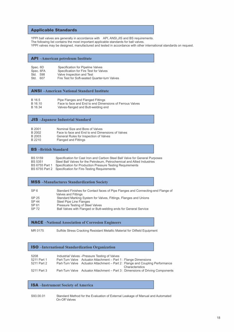
YPPI ball valves are generally in accordance with API, ANSI,JIS and BS requirements. The following list contains the most important applicable standards for ball valves. YPPI valves may be designed, manufactured and tested in accordance with other international standards on request. Spec. 6D Specification for Pipeline Valves Spec. 6FA Specification for Fire Test for Valves Std. 598 Valve Inspection and Test Std. 607 Fire Test for Soft-seated Quarter-turn Valves B 16.5 Pipe Flanges and Flanged Fittings B 16.10 Face to face and End to end Dimensions of Ferrous Valves B 16.34 Valves-flanged and Butt-welding end B 2001 Nominal Size and Bore of Valves B 2002 Face to face and End to end Dimensions of Valves B 2003 General Rules for Inspection of Valves B 2210 Flanged and Fittings BS 5159 Specification for Cast Iron and Carbon Steel Ball Valve for General Purposes BS 5351 Steel Ball Valves for the Petroleum, Petrochemical and Allied Industries BS 6755 Part 1 Specification for Production Pressure Testing Requirements BS 6755 Part 2 Specification for Fire-Testing Requirements SP 6 Standard Finishes for Contact faces of Pipe Flanges and Connecting-end Flange of Valves and Fittings SP 25 Standard Marking System for Valves, Fittings, Flanges and Unions SP 44 Steel Pipe Line Flanges SP 61 Pressure Testing of Steel Valves SP 72 Ball Valves with Flanged or Butt-welding ends for General Service MR 0175 Sulfide Stress Cracking Resistant Metallic Material for Oilfield Equipment 5208 Industrial Valves –Pressure Testing of Valves 5211 Part 1 Part-Turn Valve Actuator Attachment – Part 1 : Flange Dimensions 5211 Part 2 Part-Turn Valve Actuator Attachment – Part 2 : Flange and Coupling Performance Characteristics 5211 Part 3 Part-Turn Valve Actuator Attachment – Part 3 : Dimensions of Driving Components S93.00.01 Standard Method for the Evaluation of External Leakage of Manual and Automated On-Off Valves
18
Applicable Standards
API –American petroleum Institute
ANSI –American National Standard Institute
JIS –Japanese Industrial Standard
BS –British Standard
MSS –Manufactures Standardization Society
NACE –National Association of Corrosion Engineers
ISO –International Standardization Organization
ISA –Instrument Society of America
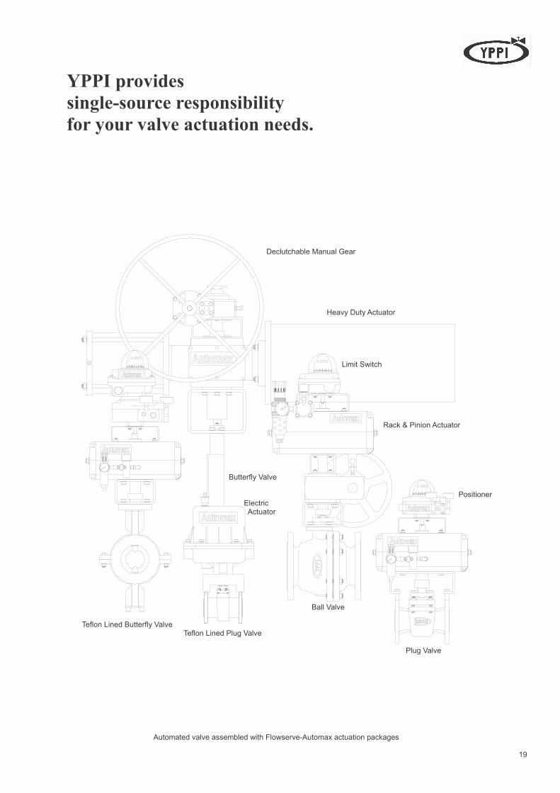
YPPI provides
single-source responsibility
for your valve actuation needs. Declutchable Manual Gear Heavy Duty Actuator Limit Switch Rack & Pinion Actuator Butterfly Valve Positioner Electric Actuator Ball Valve Teflon Lined Butterfly Valve Teflon Lined Plug Valve Plug Valve Automated valve assembled with Flowserve-Automax actuation packages
19
From the Cradle
To the Grave for Valves
Head Office :
Young Poong BLDG, Non Hyung Dong, Kang Nam Gu, Seoul, Korea TEL (02) 519-3524, 3526, 3528, 3030 FAX (02) 519-3525
Ulsan Office :
505, Dae Jung Ri, Onsan Eup, Uljin Gu, Ulsan, Kyungsang Nam Do, Korea TEL (052) 239-9963 FAX (052) 238-2338
Factory : 491-3, Mock Nae Dong, An San Si, Kyungki DO, Korea TEL (031) 491-5581 – 4 FAX (031) 492-6496
Yeosoo Office :
50-4, Sunwon Dong, Yeosoo, Junla Nam Do, Korea TEL (061) 682-5033, 5004 FAX (061) 682-3132
Cast : Foundry
368-158, Kyung Seo Dong, Seo Gu, Inchun, Korea TEL (032) 561-5581 FAX (032) 561-5580
URL : E-mail (sales)
http://www.yppc.co.kr [email protected]
YOUNG POONG PRECISION CORPORATION Bulletin YB-11-B (May 2003) This catalogue is subject to change without notice.
Distributed by: