yokohama projectaz545403.vo.msecnd.net/uploads/2015/03/7-mayekawa.pdf · 2015-03-24 · 3. dc hts...
TRANSCRIPT

Yokohama Project
- Demonstration of High Temperature
Superconducting Cable -
March 2015
MAYEKAWA MFG. CO., LTD.

1. Project overview and High Temperature superconducting (HTS) cable system.
2. High performance refrigerator for HTS cable.
3. DC HTS Power Transmission Line.
O U T L I N E

1. Project overview and HTS cable system

Advantages of HTS cable system
600800
2100
340
Conventional
Cable
Troughing
Tunnel
[size: mm]
150
230
Superconducting cable
150
Conduit
Conventional cable
275 kV, 700 MVA/3cc
HTS cable
66 kV, 700 MVA/3cc
HTS cable will be applied to power plant in service, conduit of
urban area and long distance & high power transmission.
Large capacity : equivalent to conventional cable with lower voltage.
HTS cable is able to reduce number of sub-station.
Compact size : installed within small conduit in urban area.
HTS cable can be reduced the tunnel construction cost.
Low loss : less than 1/2 compared with conventional cable.
Impossible structure of electricity stealing.
Right on way : protect natural scenery. Not influenced magnetic field.

Project overview
Project members
Project outlines
Asahi S/S, Yokohama, TEPCO’s power system
AC 66 kV - 2 kA - 200 MVA class HTS cable with 1G DI-BSCCO wire
Compact 3-in-One cable design for 150 mm conduit
Approx. 250 meter cable with a joint and terminations
TEPCO
SEI
MAYEKAWA
Host power company
HTS cable system design,
manufacture and installation
Cooling system design, manufacture and
Installation. Refrigerator development
Supported by NEDO & MTEI
Tokyo
Site
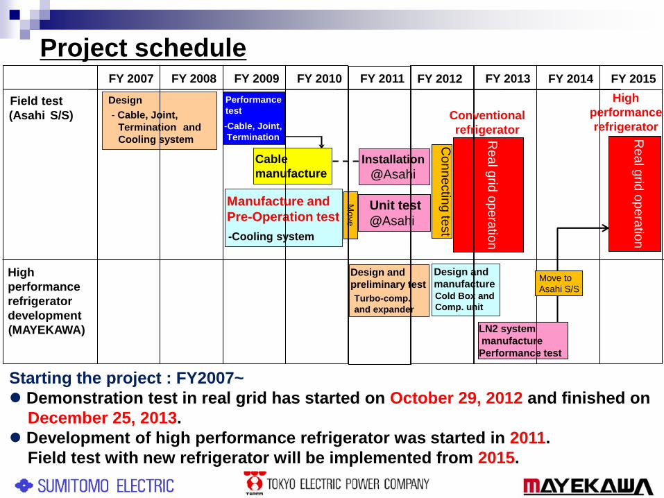
Project schedule
Starting the project : FY2007~
Demonstration test in real grid has started on October 29, 2012 and finished on
December 25, 2013.
Development of high performance refrigerator was started in 2011.
Field test with new refrigerator will be implemented from 2015.
FY 2010
(Asahi S/S)
FY 2013FY 2009FY 2008FY 2007
Field test
FY 2012FY 2011
Manufacture and
Pre-Operation test
-Cooling system
(MAYEKAWA)
High
performance
refrigerator
development
Design
- Cable, Joint,
Termination and
Cooling system
Installation
@Asahi
Unit test
@AsahiC
on
ne
ctin
g te
st
Re
al g
rid o
pe
ratio
n
Design and
preliminary test
Turbo-comp.
and expander
Performance
test
Design and
manufactureCold Box and
Comp. unit
LN2 system
manufacture
Performance test
-Cable, Joint,
Termination
Cable
manufacture
Move
FY 2014 FY 2015
Re
al g
rid o
pe
ratio
n
Move to
Asahi S/S
Conventional
refrigerator
High
performance
refrigerator

154kV bus line
【Additional equipment】
HTS cable
~240 meter
LS1
LST10
CB
LS
LS
66kV bus line
CB
LS
LS
Transformer
154/66kV
3φ200MVA CB1
CB2
LS2
HTS cable is connected
low voltage of 66 kV bus line
CB:Circuit Breaker
LS:Line Switch
Circuit diagram
Line switch (SCT10)
Is installed in by-pass
circuit for emergency

Trans
154/66kV
200MVA
Monitoring
house
Joint
CB
CH
LS1
CB1
CH
LS10
CB2
T2 T1
P
Ref
Site o
ffice
LS2
~250 meter HTS cable
Terminations
Cooling system
house
Trans
154/66kV
200MVA
Monitoring
house
Joint
CB
CH
LS1
CB1
CH
LS10
CB2
T2 T1
P
Ref
Site o
ffice
LS2
~250 meter HTS cable
Terminations
Cooling system
house
Layout of test center in Asahi S/S
Terminations
HTS cable
Cable joint
Cooling system house
66 kV XLPE cable
66 kV bus line
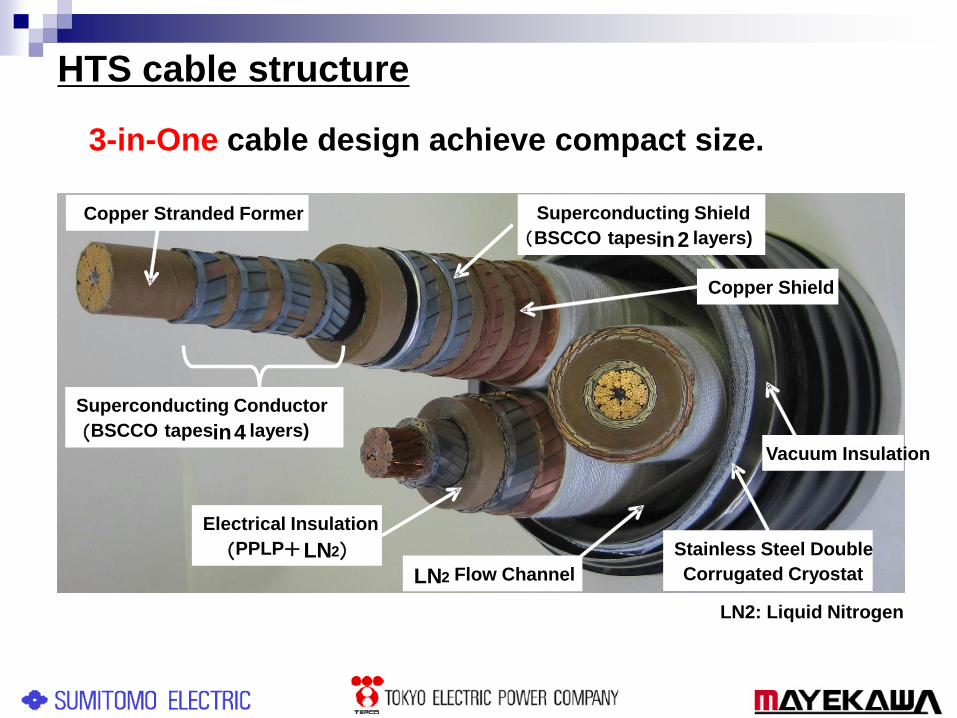
Copper Stranded Former
Electrical Insulation
(PPLP+LN2)LN2 Flow Channel
Superconducting Shield
(BSCCO tapesin2 layers)
Superconducting Conductor
(BSCCO tapesin4 layers)
Stainless Steel Double
Corrugated Cryostat
Copper Shield
3-in-One cable design achieve compact size.
HTS cable structure
Vacuum Insulation
LN2: Liquid Nitrogen

Characteristics for HTS Cable System
Cable Low heat loss AC loss of 1 W/m/ph @ 2 kA
Heat loss of 3 W/m
Withstand against fault
current
Capable of bearing Short circuit current
with 31.5kA, 2sec @ 66 kV
Cooling
system
w/o LN2 consumption
w/o vaporization
for high voltage dielectric
properties
Keep LN2 in Sub-cooled state
• Temperature : 67 to 77 K
• Pressure : 0.2 to 0.5 MPaG
• Circulate flow rate : 40 L/min
Maintenance without
shutdown
Apparatus redundancy & automatic
switching at their failure
Operation Automatic control on LN2
state without operator
Establish remote observation / alarm
system

Cooling system(1st Generation)
Refrigerators
Reservoir
Pumps
Apparatus Spec Unit(s)Redun-
dancy
Refrigerator
(Stirling type)1 kW @ 77 K 6 1 unit
Pump
(centrifugal type)40 L/min 2 1 unit
Reservoir 1000 L 1 -
ReservoirPump
CableRef.:Refrigerator
LN2
Cable
Heater
Flow meter
Ref.
Ref.
Ref.
Ref.
Ref.
Ref.
F
M
M
Motor
Valve

65
69
73
77
81
Tem
pera
ture
[K]
0
0.4
0.8
1.2
1.6
30
35
40
45
50
10/28 12/27 2/25 4/26 6/25 8/24 10/23 12/22
Pre
ssure[M
PaG
]
Ele
ctr
ic c
urr
ent[kA
ms]
Flo
w rate[L
/min]
DATE
Results of operational state
System was stable in the state of constant
and change of the operation temperature
LN2 conditions remained
steady for one year
Items Results of demonstration test
Periodical inspection 10 Jun 2013 ~ 21 Jun 2013, 22 July 2013 ~ 22 July 2013
Maximum electric current 1127 A (August 10 2013)
Voltage 63.9 kV ~ 67.1 kV
LN2 temperature
LN2 Pressure
Flow rateElectric Current

2. High performance refrigerator for HTS
cable
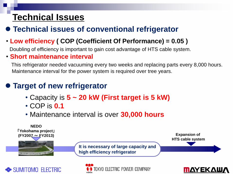
Technical Issues
Technical issues of conventional refrigerator
• Low efficiency ( COP (Coefficient Of Performance) = 0.05 )
Doubling of efficiency is important to gain cost advantage of HTS cable system.
• Short maintenance interval
This refrigerator needed vacuuming every two weeks and replacing parts every 8,000 hours.
Maintenance interval for the power system is required over tree years.
• Capacity is 5 ~ 20 kW (First target is 5 kW)
• COP is 0.1
• Maintenance interval is over 30,000 hours
Target of new refrigerator
NEDO
「Yokohama project」(FY2007 ~ FY2013) Expansion of
HTS cable system
It is necessary of large capacity and
high efficiency refrigerator
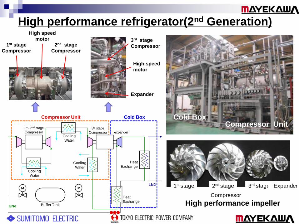
High performance refrigerator(2nd Generation)
1st stage 2nd stage 3rd stage Expander
Compressor
Cold BoxCompressor Unit
High performance impeller
Cooling
Water
Compressor Unit Cold Box
LN2
GNe
Cooling
Water
Cooling
Water
Heat
Exchange
Heat
Exchange
1st - 2nd stage
Compressor3rd stage
Compressor expander
MM
Buffer Tank
1st stage
Compressor
2nd stage
Compressor
3rd stage
Compressor
Expander
High speed
motor
High speed
motor
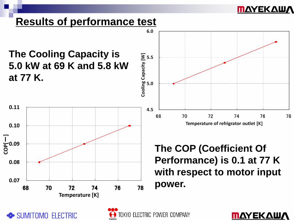
The Cooling Capacity is
5.0 kW at 69 K and 5.8 kW
at 77 K.
The COP (Coefficient Of
Performance) is 0.1 at 77 K
with respect to motor input
power.0.07
0.08
0.09
0.10
0.11
68 70 72 74 76 78
CO
P[-
]
Temperature [K]
Results of performance test
3. DC HTS Power Transmission Line

The losses of DC superconducting power
transmission line are under 1~2 %.
DC superconducting cable enables DC power
transmission with low voltage and large current.
DC power transmission with extremely long
distance and large capacity is possible without
increasing voltage.
Merits of DC HTS Power Transmission Line
Terminal
Cryo-cooler &
Circulation pump
Completed in March 2010
Terminal
Cryo-pipe
Chubu University
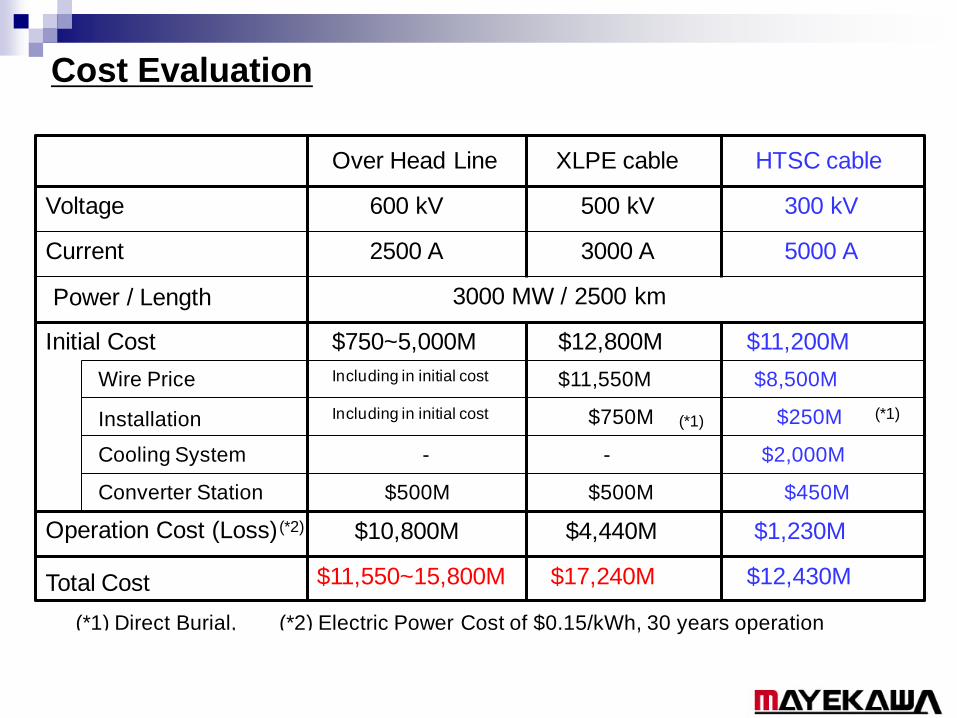
Cost Evaluation
Over Head Line HTSC cableXLPE cable
Voltage
Current
Power / Length
Initial Cost
Cooling System
Converter Station
Operation Cost (Loss)
Total Cost
600 kV 300 kV 500 kV
3000 MW / 2500 km
2500 A 3000 A 5000 A
Wire Price
Installation
$500M $500M $450M
- - $2,000M
$250M$750M
Including in initial cost
Including in initial cost
$11,550M
$4,440M
$11,200M
$17,240M
$8,500M
$12,800M
$1,230M
$12,430M
$10,800M
$750~5,000M
$11,550~15,800M
(*2) Electric Power Cost of $0.15/kWh, 30 years operation
(*1)
(*2)
(*1) Direct Burial,
(*1)

Summary
Demonstration test was carried out for year
and successfully finished.
We are successful in developing the high
performance refrigerator for HTS.
DC HTS cable enable long distance power
transmission with low losses.

Thank you