y p powerply er installation w manual o p · tools and product knowledge, ... powerply standard fr...
TRANSCRIPT

PO
WE
Rp
lyTremco® Roofing & Building Maintenance
3735 Green Road • Beachwood, Ohio 44122216.292.5000 • www.tremcoroofing.com
© 2014 Tremco Roofing and Building MaintenanceAll rights reserved
POWERplyInstallation Manual
®
Rev.9/14

PO
WE
Rp
lyTremco® Roofing & Building Maintenance
3735 Green Road • Beachwood, Ohio 44122216.292.5000 • www.tremcoroofing.com
© 2014 Tremco Roofing and Building MaintenanceAll rights reserved
Ta b l e o f C o n T e n T s
Introduction ......................................................................................1
POWERply Membrane Products......................................................2
Membrane Configurations ............................................................2-5
General Requirements ................................................................6-12
Decks ...........................................................................................6
Vapor Retarder/Air Barrier ........................................................6-7
Roof Insulation..........................................................................7-8
Insulation Attachment.............................................................7-11
Backnailing for High Slope ...................................................11-12
Spray Equipment ......................................................................13-19
Pumps ..................................................................................13-15
Heat Exchange Units ............................................................15-18
Spray Tips.............................................................................18-19
75 pound roller ...............................................................................20
Heat Welding Equipment................................................................21
Cold Weather Storage & Application Recommendations.........22-23
Hot Bitumen Application...........................................................24-25
Torch Application ......................................................................26-27
Cold Process Application .........................................................28-29
POWERply T24 MB/POWERply White on White Adhesive ......30-31
POWERply Self Adhesive Application ......................................32-33
Flashings...................................................................................34-41
Heat Welding Procedure ...........................................................42-44
POWERply T24 Cleaning Recommendations ................................45
MB Blister: Cold Adhesive Repair ..................................................46
MB Blister: Torch Repair ................................................................47
Seam Repair...................................................................................48
Detail Drawings.........................................................................49-53
C o P Y R I G H T
This document contains information that is protected by copyright. Neither extracts nor the
documentation as a whole may be photocopied, reproduced, translated, or put into data carriers
without prior approval.
PO
WE
Rp
lyTremco® Roofing & Building Maintenance
3735 Green Road • Beachwood, Ohio 44122216.292.5000 • www.tremcoroofing.com
© 2014 Tremco Roofing and Building MaintenanceAll rights reserved1
I n T R o d u C T I o n - P o W e R p l y ® I n s Ta l l aT I o n m a n u a l
The POWERply Modified Bitumen system is designed for use on low slope exterior roof
structures in North America. POWERply membranes are formulated from select asphalt
bituminous blends, various polymer modifiers, fire resistant additives, and highly engineered
reinforcing fabrics to comprise a product system designed to provide years of durable rooftop
exposure and watertight performance.
POWERply membranes are modified with styrenated butadiene (ie., SBS, SEBS, SIS) based
rubber compounds which are blended with select grades of asphalt to provide improved
bitumen performance characteristics, such as low temp flexibility, long term waterproofing, and
overall durability. POWERply membranes are also available in formulations modified with APP
(atactic polypropylene), which provides excellent bitumen performance in high temperature
applications and installations where heat welding of the membrane is required.
POWERply roof systems are primarily constructed using multi-ply bituminous membranes,
consisting of a cap sheet which provides the first line of protection from the weathering
elements, such as rain, snow, sunlight, and abrasion from foot traffic and windborne elements.
Below the surface, the POWERply system is constructed from a wide variety of additional
components, such as base sheets, adhesives (hot or cold applied), insulation courses, flashings,
and other fastening accessories. POWERply roof systems may also be finished with a variety of
coatings and surfacings, such as reflective acrylic or urethane polymeric coatings, or additional
surfacing adhesive and aggregate surfacing.
The POWERply roof system is designed to provide not only the maximum protection from the
weather, but also to provide the following features:
• Excellent service life
• Moisture resistance
• System Strength to resist effects of movement
• Fire resistanceWindstorm resistance
• Energy efficiency/thermal insulation & solar reflectance
• Resistance to roof traffic & other conditions
Tremco Roofing’s local field representatives will work with the roof designer/specifier to optimize
the roof system based on the unique set of conditions presented by each building structure and
its geographic location. The Tremco Representative is highly trained and experienced in
evaluating rooftop conditions and solving unique problems using the wide variety of diagnostic
tools and product knowledge, to deliver unique product solutions.

2
Tremco® Roofing & Building Maintenance
© 2014 Tremco Roofing and Building MaintenanceAll rights reserved
PoWeRPlY Roof sYsTems – desIGn & sPeCIfICaTIon
POWERply roof systems are constructed from at least two plies, and may be constructed from 3 or more,
depending on the design criteria. Generally, the specified POWERply top membrane identifies the roof system,
while the underlying membrane plies and membrane attachment materials are selected based on system
design criteria. Approved Tremco system configurations are defined as product combinations which have
been designated by Tremco as compatible system components and have been tested according to Tremco
and roofing industry standards and determined to exceed minimum performance standards.
PoWeRply Top membranes
The POWERply granule surfaced membranes listed in the following chart are SBS modified and manufactured
per the designated ASTM industry standard. These granule surfaced membranes are used as top membranes
in approved Tremco system configurations. All of the following membranes in this chart are suitable for
application in cold process adhesives and hot applied bitumen, unless otherwise noted:
sbs membranes – Granule surfaced sQ/roll asTm spec
POWERply Standard 1 D6163
POWERply Standard FR 1 D6163, Type I
POWERply Standard FR T24 1 D6163, Type I
POWERply Plus HT FR 1 D6163, Type III
POWERply HE FR 1 D6164, Type I
POWERply 300 FR 1 D6162, Type III
POWERply Premium FR* 1 D6162, Type III
POWERply Supreme FR* 1 D6162, Type III
*cold process application only
PoWeRply smooth membranes
The POWERply Smooth membranes listed in the following chart are SBS modified and manufactured per the
designated ASTM industry standard. All of the following membranes in this chart may be applied as top
membranes with flood and gravel surfacing in approved Tremco system configurations, and may also be used
as either intermediate and/or base membranes in approved Tremco system configurations. These membranes
are also suitable for application in cold process adhesives and hot applied bitumen, unless otherwise noted:
sbs membranes - smooth sQ/roll asTm spec
POWERply Standard Smooth 1.5 D6163, Type I
POWERply Plus HT Smooth 1.5 D6163, Type III
POWERply HE Base Sheet 1.5 D6164, Type I
POWERply 300 Smooth 1.5 D6162, Type III
POWERply Premium Smooth 1.5 D6162, Type III
POWERply Supreme Smooth 1 D6162, Type III

3
Tremco® Roofing & Building Maintenance
© 2014 Tremco Roofing and Building MaintenanceAll rights reserved
base Plies for PoWeRply systems
The base plies listed in the following chart are suitable for use as base or intermediate plies in approved
Tremco system configurations. Base plies are ideally installed in a minimum 2 ply configuration to provide
maximum moisture resistance and system strength. These membranes are also suitable for application in cold
process adhesives and hot applied bitumen, unless otherwise noted:
base Ply sQ/roll asTm/Type
THERMglass Type IV** 5 D2178, Type IV
THERMglass Premium VI** 5 D2178, Type VI
BURmastic Composite Ply HT 2 SBS, trilaminate D4601, Type II
BURmastic Composite Ply Premium 2 SBS, trilaminate D4601, Type II
BURmastic Composite Ply Supreme 2 SBS, trilaminate D4601, Type II
** hot applied only
specialty PoWeRply membranes
The POWERply membranes listed in the following chart are suitable for use as components in the following
specialty applications:
• Self Adhesive SBS Modified Membranes
• Torch Applied SBS Modified Membranes
• Torch Applied APP Modified Membranes
These membranes are suitable for use in approved Tremco roof system configurations and in combinations
and systems designated by Tremco.
specialty - Granule surfaced Type sQ/roll asTm spec
POWERply SA FR Self Adhesive 1 D6164, Type I
POWERply SBS Deluxe FR SBS torchable 1 D6162, Type III
POWERply APP FR APP torchable 1 D6222, Type I
specialty – smooth surfaced Type sQ/roll asTm spec
POWERply SA Base Sheet Self Adhesive 2 D6163, Type I
POWERply SBS Base HW SBS torchable 1 D6162, Type III
POWERply APP Base Sheet SBS torchable 1.5 D6509
POWERply APP Smooth APP torchable 1 D6222, Type I
4
Tremco® Roofing & Building Maintenance
© 2014 Tremco Roofing and Building MaintenanceAll rights reserved
PoWeRply Cold applied adhesives
The cold process membrane adhesives listed in the following chart are suitable for use in approved POWERply
roof system configurations using coverage rates and application procedures recommended by Tremco.
membrane adhesive Grade Rubber modifier
POWERply Standard Cold Adhesive Spray/Squeegee None
POWERply Standard Cold Adhesive LV Spray/squeegee None
POWERply Rubberized Cold Adhesive Spray/Squeegee SBS modified
membrane adhesive Grade Rubber modifier
POWERply White on White Adhesive Spray/Squeegee Polymeric
BURmastic Adhesive SF Squeegee only Solvent free urethane
PoWeRply Hot applied adhesives
The hot applied bituminous adhesives listed in the following chart are suitable for use in approved POWERply
roof system configurations using coverage rates and application procedures recommended by Tremco.
membrane adhesive eVT asTm/Type
Premium III Asphalt 425±25F D312, Type III
Premium IV Asphalt 450±25F D312, Type IV
sebs modifed asphalt elongation asTm
THERMastic 80 Adhesive 800% D6152
THERMastic Adhesive 1000% D6152
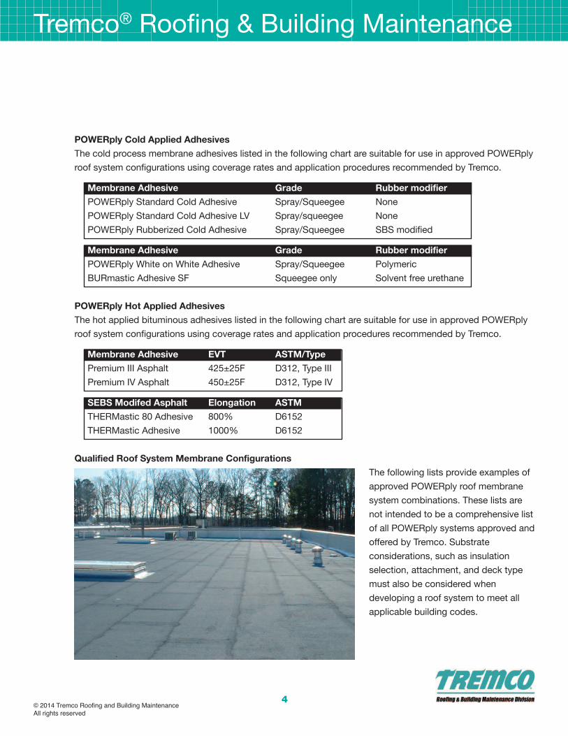
Qualified Roof system membrane Configurations
The following lists provide examples of
approved POWERply roof membrane
system combinations. These lists are
not intended to be a comprehensive list
of all POWERply systems approved and
offered by Tremco. Substrate
considerations, such as insulation
selection, attachment, and deck type
must also be considered when
developing a roof system to meet all
applicable building codes.
5
Tremco® Roofing & Building Maintenance
© 2014 Tremco Roofing and Building MaintenanceAll rights reserved
Cold Process membrane systems - examples
base membrane(s) Top membrane adhesive Type
2 ply Composite Ply HT Any POWERply Granule Membrane Any POWERply Adhesive or
BURmastic Adhesive SF
3 ply Composite Ply HT Any POWERply Granule Membrane Any POWERply Adhesive or
BURmastic Adhesive SF
2 ply Composite Ply Premium Any POWERply Granule Membrane Any POWERply Adhesive or
BURmastic Adhesive SF
2 ply Composite Ply Supreme Any POWERply Granule Membrane Any POWERply Adhesive or
BURmastic Adhesive SF
POWERply Heavy Duty Base Any POWERply Granule Membrane Any POWERply Adhesive or
BURmastic Adhesive SF
POWERply HE Base Any POWERply Granule Membrane Any POWERply Adhesive or
BURmastic Adhesive SF
POWERply 300 Smooth Any POWERply Granule Membrane Any POWERply Adhesive or
BURmastic Adhesive SF
2 ply THERMglass in hot Any POWERply Granule Membrane Any POWERply Adhesive or
BURmastic Adhesive SF
Hot applied membrane systems - examples
base membrane(s) Top membrane adhesive Type
2 ply THERMglass in hot Any POWERply Granule Membrane Premium IV Asphalt or THERMastic
3 ply THERMglass in hot Any POWERply Granule Membrane Premium IV Asphalt or THERMastic
POWERply Heavy Duty BaseAny POWERply Granule Membrane Premium IV Asphalt or THERMastic
POWERply HE Base Any POWERply Granule Membrane Premium IV Asphalt or THERMastic
POWERply 300 Smooth Any POWERply Granule Membrane Premium IV Asphalt or THERMastic

Tremco® Roofing & Building Maintenance
© 2014 Tremco Roofing and Building MaintenanceAll rights reserved
6
G e n e R a l R e Q u I R e m e n T s
Roof decks
Decking must be designed and constructed to provide sufficient support for anticipated loads without
excessive deflection or movement. Provisions for expansion and contraction shall be incorporated into the
design. The deck shall be constructed according to the deck manufacturer’s or design professional’s
specifications, following established practices, which includes attachment to the structural supports for the
building.
Tremco takes responsibility for providing quality materials and for specifications and recommendations for their
proper installation. As neither Tremco nor its representatives practice architecture or engineering, Tremco offers
no opinion, and expressly disclaims any responsibility for the soundness of any structure on which its products
may be applied.
If questions arise as to the soundness of a structure or its ability to properly support a planned installation, the
owner should obtain the opinions of competent structural engineers before proceeding. Tremco accepts no
liability for any structural failure or for resultant damages. Tremco Representatives are not authorized to vary
this disclaimer.
Decking shall be designed to provide positive drainage toward roof edges or drains. Tremco POWERply MB
systems require a minimum slope of ¼” per foot. If the deck does not meet this minimum slope requirement,
slope may be increased through the use of tapered insulation or a Tremco approved lightweight insulated
concrete system (LWIC) prior to installation of POWERply MB roof systems.
Certain roof decks may require the use of specific fastener designs in order to achieve acceptable attachment
strength. Please contact your local Tremco Representative for information on approved fastener brands
approved for use on specific roof deck types.
Vapor Retarder/air barrier
A vapor retarder and/or air barrier assembly may be specified to improve energy efficiency for the building.
This air/vapor membrane is intended to tie-in with other vapor retarder /air barrier assemblies within other parts
of the structure, such as the walls. In addition, a vapor retarder may be required if the building is located in a
cold weather climate, or where the wintertime relative humidity is considerably higher, possibly due to
processes or activities in the building which generate heat and moisture. Closely coordinate the proper tie-in of
these related vapor and air barrier components under the direction of the Architect/Engineer and with other
trades.
A vapor retarder assembly is typically applied on the top of a low slope roof deck. The best design practice is
to avoid the use of fasteners through the vapor barrier, as any breach of the vapor retarder may allow air/vapor
leakage. All deck penetrations and perimeter edge terminations must be sealed to prevent vapor leakage at
these critical areas. The following Tremco recommendations apply to vapor retarder construction based on the
roof deck type:
Tremco® Roofing & Building Maintenance
© 2014 Tremco Roofing and Building MaintenanceAll rights reserved
7
deck Type Tremco Recommended Vapor Retarder/barrier Configuration
Steel • Ply sheet vapor retarders adhered in hot or cold asphalt adhesive
over gypsum or wood fiber roof board
• Tremco AVC self adhesive membrane direct to primed deck
• Loose laid polyethylene (10 mil minimum)
Concrete Vapor retarder is fully adhered directly to deck, provided the
concrete deck is clean, dry, and primed with compatible primer.
Nailable Deck – Gypsum, Wood, LWIC Mechanically attach D4601, Type II base sheet and fully adhere
Cementitious Wood Fiber vapor retarder in hot or cold asphalt adhesive.
Acceptable vapor retarder membranes consist of the following Tremco products or commercially
available materials:
Vapor Retarder/barrier application
Tremco AVC Membrane Prime substrate & apply direct to deck
2 ply THERMglass (D2178, Type IV/VI) Apply to substrate in hot adhesive
BURmastic Composite Ply HT Apply to substrate in cold adhesive
Polyethylene (10 mil) Loose laid on deck under insulation, w/ side laps and end
laps taped.
Roof Insulation
Roof insulation boards provide several benefits within a roof assembly:
• Improved energy efficiency of the building.
• Performs as a consistent substrate for the POWERply MB roof system.
• Separates dissimilar materials.
• When tapered, improves drainage from the POWERply MB surface.
When roof insulation is used as part of a POWERply roof system, it must be manufactured for use as a roof
insulation and be approved by Factory Mutual and Underwriters Laboratories for use in the POWERply roof
system. Roof insulations are measured by R-value, and the R-value required for a building with interior
conditioned air is prescribed in the International Energy Conservation Code, with the applicable version of the
code adopted at the state or municipal level.
The International Construction Code (ICC) requires roof systems meet minimum criteria for wind uplift
resistance, as referenced in the ASCE/SEI 7 Standard. Roof system manufacturers test and obtain wind
resistance certifications for their product system assemblies according to this standard. These certifications
are offered by organizations such as Factory Mutual Approvals, Underwriter’s Laboratories, Miami-Dade
County Product Control, and ICC Evaluation Service, using testing standards which are named in the ICC.
These certifications specify the roof insulation attachment products and procedures, such as coverage rates of
adhesive brands and the fastener attachment patterns.

Tremco® Roofing & Building Maintenance
© 2014 Tremco Roofing and Building MaintenanceAll rights reserved
8
Insulation attachment for a roof system will vary based on a variety of factors, such as type of structure,
geographic location of the structure, height off the ground of the roof, and situation of the building near the
coast or in special wind zones. The Tremco Field Representative works with the building owner and/or the
Architect/Engineer to specify insulation attachment in compliance with local building code requirements.
Please refer to Tremco project specifications for these requirements. If there are any questions regarding the
insulation configuration and attachment for use in conjunction with the POWERply roof system, please contact
the local Tremco Field Representative for further information.
acceptable Insulations
The following insulations are acceptable for use in approved Tremco roof system configurations in
combinations and systems designated by Tremco.
Insulation Type asTm spec
Polyisocyanurate D1289
Mineral Fiber (Roxul) C726
Wood Fiber C208
Fiber Reinforced Gypsum (Securock) C1278
Glass Mat Reinforced Gypsum (Dens-Deck) C1177
Insulation attachment methods
Insulation systems may be secured to the structural deck using a variety of attachments and
application methods:
• Mechanically attached, with fasteners and stress plates
• Cold applied liquid or foam adhesives
• Hot applied bituminous adhesives
mechanically attached Insulation
A common specification is to secure the first layer of roof insulation to a steel deck using a fastener and plate.
This practice was implemented in the early 1980’s by the Factory Mutual Global (FMG), a commercial
insurance underwriter, and is required for their client’s buildings. FMG faced numerous insurance losses where
hot bitumen had been used to adhere insulation to steel decks on commercial structures. In the event of an
internal fire, the bitumen liquefies and feeds the fire, leading to a tremendous loss history. In addition, FMG
experienced losses due to poor choices in adhesives and due to unacceptable application practices. Due to
this loss history, FMG created a new policy requiring the first layer of insulation must be mechanically attached
to steel roof decks when installing roofs on their insured client’s buildings.
Due to the success of this policy in reducing wind and fire loss, this practice has been adopted by numerous
roofing industry specifiers. Today, even though there are now insulation adhesives on the market which exceed
code requirements for internal combustion and for wind uplift, mechanical attachment of the first layer of
insulation on steel decks remains the predominate method of application.

Tremco® Roofing & Building Maintenance
© 2014 Tremco Roofing and Building MaintenanceAll rights reserved
9
Fasteners and stress plates are designed to be used in combination with each other. Do not mix fasteners and
discs of different brands, unless the combination has been tested and approved by a code compliant testing
organization.
When installing fastener and stress plate assemblies, fasteners must be driven perpendicular to the deck. Do
not overdrive the fastener to over-compress the insulation board. Overdriving may lead to fracturing of the
insulation and the attachment may be compromised. When properly installed, the fastener and stress plate
assembly are driven tight enough so the disc will not turn when installed.
For wood roof decks, screw fasteners must penetrate 1” minimum into the deck. For ¾” plywood,
approximately ¼” shall extend through the underside of the deck.
For steel decks, the screw fastener must engage the top flange of the deck, and not the flute or bottom
corrugation. This ensures tight fastener attachment without a gap, which could contribute to fastener backout
over time. For steel decks, use the shortest screw which is at least ¾” longer than the assembly being secured.
Please refer to Tremco detail drawing section for additional recommendations regarding fastener placement
locations on roof insulation boards.
Insulation adhesives
Tremco provides liquid and foam adhesives suitable for use under the POWERply MB roof system. These
adhesives are designed to adhere acceptable roof insulation boards to approved roof substrates, such as
concrete, mechanically attached base sheets, and insulation boards.
Fas-n-FREE Adhesive is a liquid applied, pourable, bituminous, solvent free and moisture cure urethane
adhesive. Fas-n-FREE Adhesive is applied in beads to the roof substrate using a drop spreader cart which
applies the beads within 6” of the insulation board edge and in a pattern through the middle of the insulation
board. The insulation board must be stepped into place immediately after application, assuring the board is
pressed into the beads and contacts the roof substrate.
Low Rise Foam Insulation Adhesive describes a family of foamable, 2 component, solvent free and urethane
adhesive products. Low Rise Foam Insulation Adhesive products are applied in beads to the roof substrate,
using either a handheld cartridge gun or using a bulk bag pump cart application tool. After application, the
adhesive beads require a few minutes to rise and develop tack, and then the insulation boards are dropped
onto the beads and stepped into place.
Please review Tremco product literature for more information on application and performance of the Tremco
brand insulation adhesive products.
Hot applied asphalt
Hot asphalt is a traditional insulation adhesive and is acceptable for use to adhere insulation in approved

Tremco® Roofing & Building Maintenance
© 2014 Tremco Roofing and Building MaintenanceAll rights reserved
10
POWERply roof systems. Hot asphalt is acceptable for use to adhere insulation to approved roof substrates,
such as concrete, mechanically attached base sheets, and insulation boards. Tremco offers products such as
Premium III asphalt and Premium IV Asphalt, which are acceptable for use as hot applied insulation adhesive.
For application as an insulation adhesive, apply hot asphalt to the substrate in a full coverage at a rate of 30
lbs/SQ. Asphalt can be applied either by mop or by an applicator cart, at its recommended EVT (equiviscuous
temperature) range for the type of asphalt, and no lower than 400F. Immediately place the insulation boards
into the hot asphalt and step into place, assuring the corners of each board are solidly adhered.
Hot asphalt has the well earned reputation of providing the highest adhesive bond strength in the roofing
industry. However, it has a high potential for odor concerns, which must be considered when specifying this
material for use in a reroofing application where the building may be occupied and in service. There are fume
management equipment and odor masking technologies available for use which may help to alleviate these
concerns during the roof project.
Insulation Considerations
Where insulation is specified with a POWERply roof system, a minimum of two (2) layers are required for
systems over steel roof decks, due to the ability of two layers to alleviate deck movement and prevent the roof
membrane from picture framing directly over the insulation board panels.
On substrates other than steel decks, a minimum of two (2) layers of insulation are recommended.
Unless otherwise specified, a coverboard is required under all POWERply insulated roof systems. Acceptable
coverboards are either wood fiber or gypsum roof boards. Coverboards provide a protective substrate for the
roof membrane and help resist damage from traffic, hail, falling objects, etc.
Tremco recommends adhering the coverboard in POWERply roof systems rather than mechanical attachment
for the following reasons:
• Eliminate the occurrence of thermal bridging from the interior of the building to the exterior membrane,
which provides a path for heat energy through the roof insulation system and reduces thermal efficiency
• Eliminates a fastener head point and stress plate on the underside of the roof membrane, where this
uneven surface could lead to an adhesion loss or inconsistency at this point.
POWERply systems shall not be fully adhered directly to polyisocyanurate insulation, unless a coverboard is
adhered over the polyisocyanurate insulation first.
Do not apply POWERply systems over wet insulation. Wet insulation must be removed from the roof system
and replaced with dry insulation boards.
The following chart describes the Tremco approved substrate preparation and insulation attachment based on
roof deck type.

Tremco® Roofing & Building Maintenance
© 2014 Tremco Roofing and Building MaintenanceAll rights reserved
11
deck Type acceptable substrate for Insulation attachment
Steel Mechanically attach first layer; adhere subsequent layers
Concrete Prime w/ Asphalt Primer; adhere insulation layers
deck Type acceptable substrate for Insulation attachment
Wood/plywood Mechanically attach rosin and D4601, Type II base sheet
(note: mechanically attached gypsum roof board recommended)
Tectum Mechanically attach D4601, Type II base sheet
LWIC* Mechanically attach D4897, Type II venting base sheet
Gypsum Poured Mechanically attach D4897, Type II venting base sheet
Gypsum Plank Mechanically attach or adhere insulation, based on density.
Contact local Tremco Field Representative for additional info.
* Lightweight Insulating Concrete
Installation Procedures – Roof Insulation
1. Coordinate installation of POWERply roof system components so insulation is not exposed to
precipitation or left exposed at the end of the workday.
2. Install base sheet if specified and mechanically attach to substrate.
3. Install wood nailers as specified to match insulation and cricket height at perimeters.
4. Install insulation with long joints of insulation in continuous straight line with end joints staggered
between rows, abutting edges and ends between boards and secure as specified Fill gaps exceeding
¼ inch with insulation.
a. Cut and fit insulation within ¼ inch of nailers, projections, and penetrations.
5. Install additional layer(s) of insulation, taper, crickets, and coverboard over previously applied insulation
layer with long joints in continuous straight lines with end joints staggered between rows. Stagger joints
from those in previously installed layer(s) a minimum of six (6) inches in each direction.
6. Trim surface of insulation where necessary at roof drains so completed surface is flush and does not
restrict the flow of water.
7. Install and secure preformed 45-degree cant strips at junctures of POWERply roof membranes with
vertical surfaces or angle changes greater than 45-degrees.
8. Install tapered edge strips at perimeter edges of roof that do not terminate at vertical surfaces.
Insulation stops for High slope applications
For installations at roof slopes greater than 2:12 where the insulation courses are adhered, Insulation Stops
shall be mechanically attached to the roof deck. The purpose of Insulation Stops is to prevent slippage of
adhered insulation when installed at high slopes.
For roof slopes less than 2:12, Insulation Stops are not required. For roof slopes between 2:12 and 3:12,

Tremco® Roofing & Building Maintenance
© 2014 Tremco Roofing and Building MaintenanceAll rights reserved
12
Insulation Stops are required every twenty (20) feet in a direction perpendicular to the slope. For roof slopes
greater that 3:12, Insulation Stops are required every four (4) feet in a direction perpendicular to the slope.
backnailing for High slope applications
Low slope fully adhered roof membranes or plies may have a tendancy to slump or sag when installed on
slopes above 2:12. Even though a roofing adhesive may be acceptable for use in a roof system on high
slopes, the weight of the membrane or ply could potentially overcome the adhesive bond and lead to slippage,
especially at high temperatures and/or excessively high slopes.
minimize the potential for membrane slippage on high slopes:
• Run the roof membrane in the same direction as the slope (parallel to the slope, not perpendicular to the
slope). Topnail the roof membrane at the peak of the slope and cover the fasteners with a cap ply.
• Certain membrane reinforcements have sufficient strength to allow for topnailing so one can avoid nailing
in the middle of the membrane run.
• Plan the membrane installation to take advantage of the full length of the membrane. Avoid end laps in
the middle of a run from peak to valley (or eave). When an end lap must occur, make sure it aligns over an
insulation stop so the new ply can be nailed.
• Be aware of issues that may occur with adhesives. For example, softening point fallback can occur when
hot asphalt is overheated in the kettle for extended periods of time. Fallback can lead to slippage issues
of roofing plies and membranes which are adhered in hot asphalt that has been affected by this condition.
backnailing for roof slopes between 2:12 (16.6%) and 3:12 (25%):
• Mechanically attach wood blocking as an insulation stop to the deck 20’ (6m) on center perpendicular
to the slope.
• Apply roof membrane parallel to the slope
• During application, backnail each roofing ply to the wood blocking staggered 3 inch (75 mm) on center on
the back edge of the ply (the section covered by the overlapping ply).
• Fasteners shall be covered by a minimum of two plies.
backnailing for roof slopes of 3:12 (25%) and greater:
• Mechanically attach wood blocking to the deck as an insulation stop 4’ (1220 mm) on center
perpendicular to the slope.
• Apply roof membrane parallel to the slope.
• During application, backnail each roofing ply to the wood blocking staggered 3 inch (75 mm) on center on
the back edge of the ply (the section covered by the overlapping ply).
• Fasteners shall be covered by a minimum of two plies.
Tremco® Roofing & Building Maintenance
© 2014 Tremco Roofing and Building MaintenanceAll rights reserved
13
s P R aY e Q u I P m e n T
Roofing Pump systems
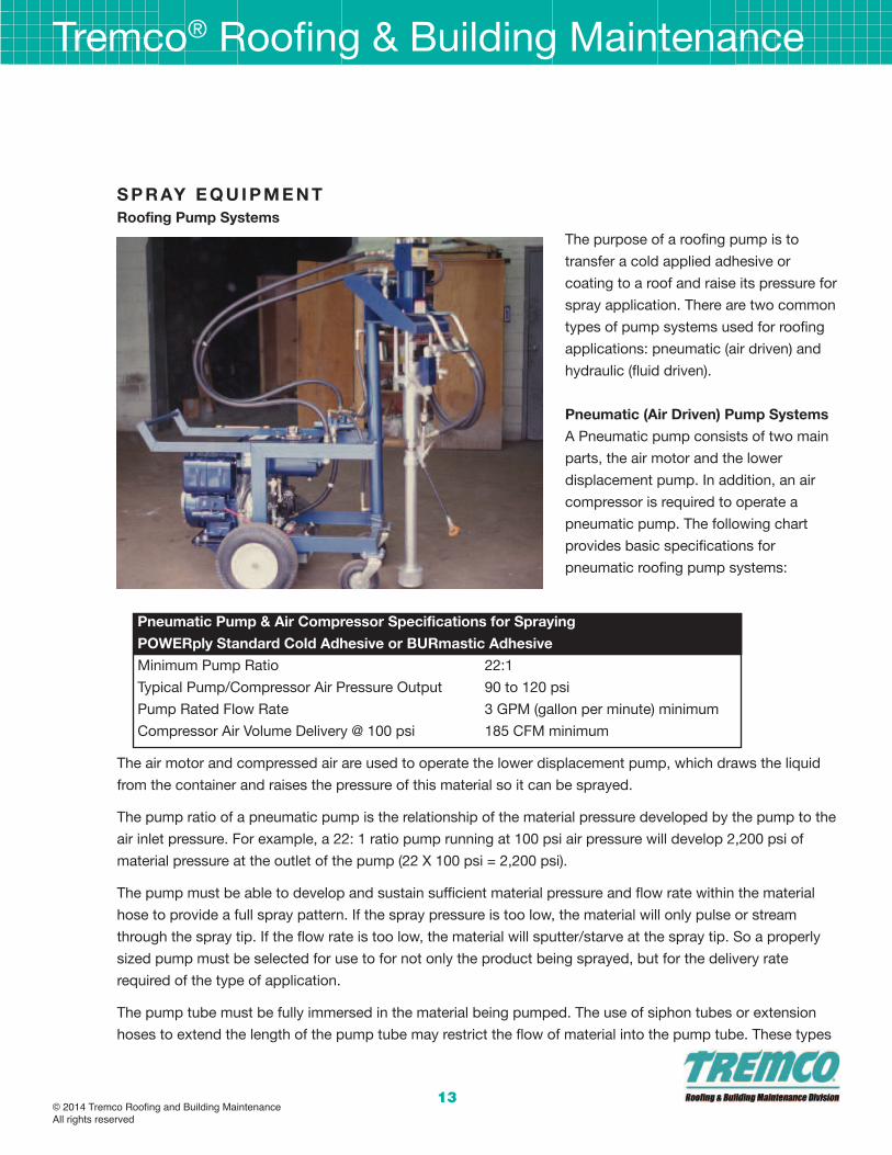
The purpose of a roofing pump is to
transfer a cold applied adhesive or
coating to a roof and raise its pressure for
spray application. There are two common
types of pump systems used for roofing
applications: pneumatic (air driven) and
hydraulic (fluid driven).
Pneumatic (air driven) Pump systems
A Pneumatic pump consists of two main
parts, the air motor and the lower
displacement pump. In addition, an air
compressor is required to operate a
pneumatic pump. The following chart
provides basic specifications for
pneumatic roofing pump systems:
Pneumatic Pump & air Compressor specifications for spraying
PoWeRply standard Cold adhesive or buRmastic adhesive
Minimum Pump Ratio 22:1
Typical Pump/Compressor Air Pressure Output 90 to 120 psi
Pump Rated Flow Rate 3 GPM (gallon per minute) minimum
Compressor Air Volume Delivery @ 100 psi 185 CFM minimum
The air motor and compressed air are used to operate the lower displacement pump, which draws the liquid
from the container and raises the pressure of this material so it can be sprayed.
The pump ratio of a pneumatic pump is the relationship of the material pressure developed by the pump to the
air inlet pressure. For example, a 22: 1 ratio pump running at 100 psi air pressure will develop 2,200 psi of
material pressure at the outlet of the pump (22 X 100 psi = 2,200 psi).
The pump must be able to develop and sustain sufficient material pressure and flow rate within the material
hose to provide a full spray pattern. If the spray pressure is too low, the material will only pulse or stream
through the spray tip. If the flow rate is too low, the material will sputter/starve at the spray tip. So a properly
sized pump must be selected for use to for not only the product being sprayed, but for the delivery rate
required of the type of application.
The pump tube must be fully immersed in the material being pumped. The use of siphon tubes or extension
hoses to extend the length of the pump tube may restrict the flow of material into the pump tube. These types

Tremco® Roofing & Building Maintenance
© 2014 Tremco Roofing and Building MaintenanceAll rights reserved
14
of extensions should not be used unless otherwise designed or recommended by the pump equipment
supplier.
air Compressor
The purpose of the air compressor is to provide the required volume of air at a specified pressure for the
efficient operation of the pump.
These values provided in the previous chart are recommendations for the use of a spraying system consisting
of one pneumatic pump. A typical pneumatic roofing pump requires approximately 110 CFM to operate
efficiently. When running two or more pneumatic pumps, an air compressor which can deliver a greater volume
of air must be used. Two pumps will double the volume of air which is required for proper operation.
A pump may seem to operate on a lower than recommended air volume or air pressure. However, at these
lower air volumes or air pressures, the pump will not be operating at its designed efficiency levels. This will
result in a reduced material flow rate and reduced spray pressure. The pump will cycle slowly, if it even cycles
at all.
Contact the manufacturer of the pump for more information on the minimum air volume required for the
efficient operation of your pneumatic pump.
air Compressor Components -air filter, lubricator, Regulator & shutoff Valve
The use of an air filter unit is recommended in order to remove foreign particles and reduce moisture in the air
supply.
The use of an air lubricator may help to smooth the movement and extend the life of the air motor of the pump
by applying a measured amount of lubricant into the air supply. A light weight misting oil is typically used in an
air lubricator. Some air motors do not require lubrication and may in fact be damaged by this procedure.
Contact your pump manufacturer for specific recommendations.
The use of an air regulator allows for precise control of the air pressure into the pump.
An air shutoff valve is highly recommended for all pneumatic pumps. This will allow for the immediate or
emergency shut-offs of the pump by closing the air line.
All of the above described air components must be designed and rated for use under the maximum
temperatures, maximum air pressures, and maximum airflow volumes (185 CFM) which the air compressor will
provide. Consult the manufacturer of the air compressor, pump, or air components for more specific
recommendations.
air Hose
Air Hose used to connect the compressor to the pneumatic pump should be heavy duty and reinforced to
withstand pressures of at least 200 psi.

Tremco® Roofing & Building Maintenance
© 2014 Tremco Roofing and Building MaintenanceAll rights reserved
15
Minimum ID (inside diameter) required will typically be 3/4", using either Sleeve Type Air Coupler (Quick
Connect) assemblies or Chicago Style Fittings for connecting components and sections.
Hydraulic (fluid driven) Pump systems
A Hydraulic pump consists of two parts, the fluid motor and the displacement pump. This pump operates
along the same basic principle as pneumatic pumps, except that hydraulic fluid is used to operate the fluid
motor rather than compressed air. The following chart describes the minimum recommendations for a
hydraulic roof pump spraying system:
Hydraulic Pump specifications for spraying
PoWeRply standard Cold adhesive and buRmastic adhesive
Minimum Output Material Pressure 2,200 psi
Flow Rate (Delivery) 3.0 GPM (gallons per minute, minimum)
Size of Material Outlet Fitting ¾” NPT minimum
Hydraulic pumps are rated by the maximum material output pressure, not by pump ratio.
A hydraulic pump operates by circulating hydraulic fluid through the fluid motor at pressures in the range of800
to 1 ,200 psi. This high pressure fluid operates a piston in the fluid motor. The piston's energy is transferred to
the displacement pump. This in turn raises the pressure of the material, causing it to be pumped and sprayed.
Most hydraulic pumps used in the roofing industry to spray apply BURmastic are self contained units. These
pump units contain a gasoline engine (typical 18 HP) to drive the hydraulic fluid to the material pump. The
pump unit is mounted on a two wheel cart frame, making it extremely portable. Long lengths of material hoses
can be eliminated, since these pumps can be brought almost to the point of application on the roof.
The pump tube must be fully immersed in the material being pumped. The use of siphon tubes or extension
hoses to extend the length of the pump tube may restrict the flow ofmaterial into the pump tube. These types
of extensions should not be used unless otherwise approved by Tremco.
Comparison of Hydraulic and Pneumatic Pumps
A hydraulic pump system has better energy transfer efficiency compared to a compressed air system. In
addition, a hydraulic system will operate without water condensation or icing problems in cold weather
because there is no air exhaust from a hydraulic pump system. Hydraulic pumping units are typically self
contained, consisting of a gas driven hydraulic motor and the displacement pump on a portable cart.
Disadvantages of a hydraulic system include dependence on the hydraulic oil, which must be properly
maintained in order to be free of contamination, to keep fluids at proper levels, and to operate within the
proper temperature range.
A pneumatic pump system requires a separate air source to operate the material pump. A 185 CFM air
compressor is required to run a pneumatic pump. This type of compressor is typically mounted on a trailer to
be towed by a truck.

Tremco® Roofing & Building Maintenance
© 2014 Tremco Roofing and Building MaintenanceAll rights reserved
16
Pneumatic systems are subject to water condensation and icing in cold weather. Pneumatic pumps are
typically less expensive than hydraulic pumps. However, when the cost of the needed compressor is
considered, the final system prices are comparable.
Heat exchange units
A tube-fired, thermostatically controlled oil bath heat exchange unit is the only recommended method of
warming bituminous adhesives such as POWERply Standard Cold Adhesive and BURmastic Adhesive for
spray application. The following criteria help to describe the equipment and typical operating conditions of a
heat exchange unit for bituminous roofing adhesives:
specification for Heat exchange unitfor bituminous Roofing adhesives
Pipe Coils Schedule 80, boiler grade minimum
Heat Transfer Oil, temperature range 250° to 350°F
In a commercial heat exchange unit, the bituminous adhesive is pumped through pipe coils submerged in a
double walled, insulated container of heat transfer oil. The bituminous adhesive is warmed to an output
temperature of 90° to l00°F, depending on the temperature of the surrounding heat transfer oil.
Follow all operating and safety procedures per the manufacturer of the heat exchange unit.
material Hoses - (sae J517 100 series, Type aT)
A high pressure, hydraulic hose conforming to SAE J517 100 Series, Type AT must be used as a material line
for POWERply Standard Cold Adhesive and BURmastic Adhesive in all pressurized transfers from the pump to
the spray wand.
This type of material hose utilizes synthetic rubber in both the tube and cover material. Depending on the
pump output spray pressure range, the specified hydraulic hose will contain one or more braids of wire
reinforcement. Select the material hose so that its designed working pressure is equal to, or exceeds the
maximum material output delivery pressure.
The material hose must be approved for use with fluids containing petroleum and paint solvents. The specified
service temperature range is from -40° to 200°F.
To achieve a good material spray pattern, it is important to have sufficient material pressure at the spray tip.
However, material pressure drops off steadily as the material hose length is increased. Therefore, it is very
important to keep the material hose length to a minimum in order to maintain proper material pressure at the
spray tip.
The following reference chart relates the hose diameter and working pressure rating to the SAE spec for a
particular fluid transfer hose:

Tremco® Roofing & Building Maintenance
© 2014 Tremco Roofing and Building MaintenanceAll rights reserved
17
maximum Working Pressure (PsI) of sae 100R Type aT fluid Hose
Hose Id sae100R2 sae100R8 sae100R9 sae100R10 sae100R11 sae100R12 sae100R13
½” 3,500 3,500 4,000 6,250 7,500 4,000 -5/8” 2,750 2,750 - - - 4,000 -
¾” 2,250 2,250 3,000 5,000 6,250 4,000 5,000
1” 2,000 2,000 3,000 4,000 5,000 4,000 5,000
1 ¼” - - 2,500 3,000 3,500 3,000 5,000
1 ½” - - 2,500 2,000 3,000 2,500 -
Reference: SAE J517 (April 91) Hydraulic Hose
Typically, a 22: 1 ratio pump can be used to spray material through 200' to 300' of standard 3/4" ID (Inside
Diameter) material hose with 70°F material and air temperatures. By using a Heat Exchange Unit and a higher
output pressure pump, longer lengths of material hose, up to 500', may potentially be used.
For pumping over long distances, always use a 1" ID material hose between the pump and the Heat Exchange
Unit. Next, use a large diameter hose (1" ID) material hose for as long a distance as possible to reduce the
pressure drop through the hose. Then, using a reducing coupler, connect a smaller sized material hose to the
spray wand for the last 15 - 20'. This will make the line easier to handle for the sprayer.
Inspect hoses regularly to assure safe spray operations. To prevent material leakage in case a hose bursts,
thread the pressurized material line through a larger diameter hose (an old fire hose.) Always protect sensitive
or difficult to clean building features from accidental leaks.
material Hose Connections
The threaded hose connections should be constructed of a non-corrosive metal. Materials such as Brass,
Stainless Steel w/ Zinc plating, or Steel w/ Chrome plating should be used because of their corrosion
resistance. Aluminum fittings should not be used since they do not have the long term strength and durability
needed in a threaded connection which will be frequently loosened and tightened by wrench.
It is recommended to set up the material hoses with threaded male fittings and use female swivel fittings to
connect the sections of hose.
Quick connects are not recommended for material hoses since they are typic all y not rated for high pressure
applications. However, they are commonly used for air connections.
spray Wands
POWERply Standard Cold Adhesive and BURmastic Adhesive must be applied using airless pump and
spraying systems. Using an air-assisted spray system would lead to uncontrollable overspray and poor control
of coverage rates.
Tremco® Roofing & Building Maintenance
© 2014 Tremco Roofing and Building MaintenanceAll rights reserved
18
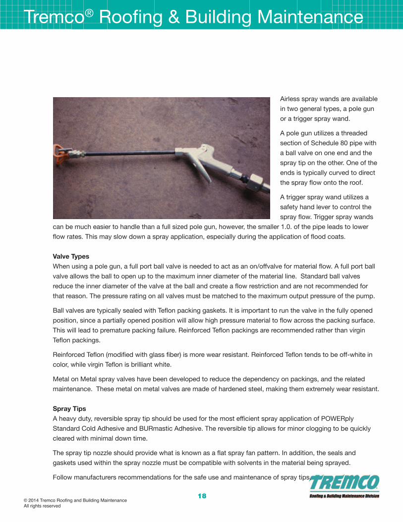
Airless spray wands are available
in two general types, a pole gun
or a trigger spray wand.
A pole gun utilizes a threaded
section of Schedule 80 pipe with
a ball valve on one end and the
spray tip on the other. One of the
ends is typically curved to direct
the spray flow onto the roof.
A trigger spray wand utilizes a
safety hand lever to control the
spray flow. Trigger spray wands
can be much easier to handle than a full sized pole gun, however, the smaller 1.0. of the pipe leads to lower
flow rates. This may slow down a spray application, especially during the application of flood coats.
Valve Types
When using a pole gun, a full port ball valve is needed to act as an on/offvalve for material flow. A full port ball
valve allows the ball to open up to the maximum inner diameter of the material line. Standard ball valves
reduce the inner diameter of the valve at the ball and create a flow restriction and are not recommended for
that reason. The pressure rating on all valves must be matched to the maximum output pressure of the pump.
Ball valves are typically sealed with Teflon packing gaskets. It is important to run the valve in the fully opened
position, since a partially opened position will allow high pressure material to flow across the packing surface.
This will lead to premature packing failure. Reinforced Teflon packings are recommended rather than virgin
Teflon packings.
Reinforced Teflon (modified with glass fiber) is more wear resistant. Reinforced Teflon tends to be off-white in
color, while virgin Teflon is brilliant white.
Metal on Metal spray valves have been developed to reduce the dependency on packings, and the related
maintenance. These metal on metal valves are made of hardened steel, making them extremely wear resistant.
spray Tips
A heavy duty, reversible spray tip should be used for the most efficient spray application of POWERply
Standard Cold Adhesive and BURmastic Adhesive. The reversible tip allows for minor clogging to be quickly
cleared with minimal down time.
The spray tip nozzle should provide what is known as a flat spray fan pattern. In addition, the seals and
gaskets used within the spray nozzle must be compatible with solvents in the material being sprayed.
Follow manufacturers recommendations for the safe use and maintenance of spray tips.
Tremco® Roofing & Building Maintenance
© 2014 Tremco Roofing and Building MaintenanceAll rights reserved
19
spray Tips specifications for PoWeRply standard Cold adhesive
Orifice Size Range 0.052" to 0.072"
Spray Fan Angle 45° to 65°
Spray Fan Width (at 1 foot) Approx 8" to 14"
Gasket Type Teflon or Viton
squeegee application
A neoprene rubber squeegee is recommended for manual application of POWERply Standard Cold Adhesive
and BURmastic Adhesive SF. A serrated blade, with jagged rubber tines (teeth) will allow the adhesive to be
evenly spread across the substrate.
By selecting the proper height of the notching on the blade, the coverage rate can be easily controlled. In
addition, the pressure exerted on the blade helps to control coverage rates. Serration notches of 3/16" to 1/4"
are sufficient to allow for the application of adhesive at the proper coverage rate. However, good roofing
practice dictates that an area should be marked off to confirm the proper material coverage rate. Alternately,
use a squeegee designated 40 mil or 45 mil for interply application and 75 or 90 mil for flood coat application.
Squeegee blades must be replaced when the tines become rounded and worn. Wipe the squeegee blade
clean using Mineral Spirits after the application. Soaking the rubber blades in solvent will cause them to swell
and render them useless.
Tremco® Roofing & Building Maintenance
© 2014 Tremco Roofing and Building MaintenanceAll rights reserved
20
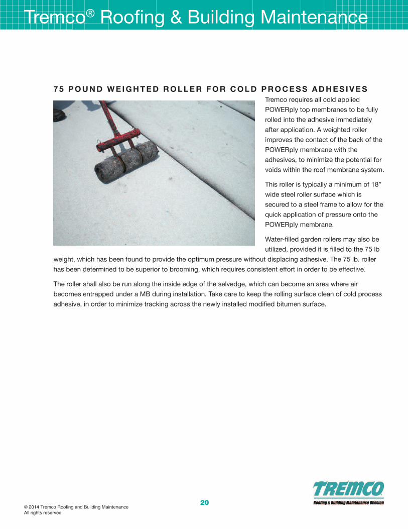
7 5 P o u n d W e I G H T e d R o l l e R f o R C o l d P R o C e s s a d H e s I V e s
Tremco requires all cold applied
POWERply top membranes to be fully
rolled into the adhesive immediately
after application. A weighted roller
improves the contact of the back of the
POWERply membrane with the
adhesives, to minimize the potential for
voids within the roof membrane system.
This roller is typically a minimum of 18”
wide steel roller surface which is
secured to a steel frame to allow for the
quick application of pressure onto the
POWERply membrane.
Water-filled garden rollers may also be
utilized, provided it is filled to the 75 lb
weight, which has been found to provide the optimum pressure without displacing adhesive. The 75 lb. roller
has been determined to be superior to brooming, which requires consistent effort in order to be effective.
The roller shall also be run along the inside edge of the selvedge, which can become an area where air
becomes entrapped under a MB during installation. Take care to keep the rolling surface clean of cold process
adhesive, in order to minimize tracking across the newly installed modified bitumen surface.

Tremco® Roofing & Building Maintenance
© 2014 Tremco Roofing and Building MaintenanceAll rights reserved
21
H e aT W e l d I n G e Q u I P m e n T
Leister, a leading manufacturer of heat-welding equipment, has
developed the Bitumat B2 heat seaming unit for use in the hot air
welding of modified bitumen membranes.
The Bitumat B2 is an automatic heat-seaming unit specifically
designed to seal the side and end laps of modified-bitumen
membranes. It differs from the Varimat (used on thermoplastic single
plies) in several ways:
• 4” wide heat nozzle – Allows the entire selvage to be seamed in
one pass.
• Air Volume Control – Reduces bitumen “blow out” from the
seam.
• Seam Air Dam – Prevents air from being blown back into the
adhered sheet.
These improvements correct the issues experienced when heat
seaming MB’s using a heat welding unit intended for single ply
thermoplastic membranes, such as the Leister Varimat. The wide air nozzle permits the seam to be fully welded
shut while producing a bitumen bead bleed on both the seam and underside the MB lap. The air volume
control allows the operator to eliminate the bitumen splatter blowing out of the seam and onto the granules.
The seam air dam prevents the hot air from being blown under the MB membrane and potentially delaminating
the adhered membrane.
Tremco Technical Services has verified that POWERply MB membranes can be effectively heat welded using
the Bitumat B2 unit. Lap shear testing conducted in the Tremco Research Center demonstrated that a heat
welded seam is stronger than an adhered seam. The heat welded seam becomes instantly watertight and can
easily be inspected both visually for bleed out and with a membrane probe to assure a solid weld.
The Bitumat B2 hot-air welder and heat-seaming application techniques represent a best practice for the
installation of POWERply MB’s. The Roofing and Building Maintenance Division Technical Services Group
strongly recommends this application method and equipment for the installation of Tremco POWERply roof
systems.

Tremco® Roofing & Building Maintenance
© 2014 Tremco Roofing and Building MaintenanceAll rights reserved
22
C o l d W e aT H e R s T o R a G e a n d a P P l I C aT I o n R e C o m m e n d aT I o n s
Outdoor temperatures of 45° F and rising are usually acceptable conditions for roof work. Some types of roof
work may take place under cooler weather conditions, provided the proper methods are in place to deliver the
materials to the point of application in a workable condition. Substrate conditions and sufficient cure time for
materials must also be taken into consideration. Evaluate all factors related to environmental conditions prior to
installation of any roof material.
material storage and Handling:
Upon receiving roll goods, remove or
slit tops of plastic shipping packaging
and cover all rolls with canvas tarpaulin
and secure. Protect all roofing material
from exposure to snow, ice and water.
Roofing products shall be stored on
pallets or dunnage off the ground or
roof surface. Protect stored liquid
materials from direct sunlight.
Determine if products require special
storage conditions or temperature
ranges and make provisions to follow
manufacturer’s specific recommendations.
Protect roof insulation from physical damage and deterioration by sunlight, moisture, soiling, and other forces.
Store in a dry location. Comply with insulation manufacturer’s written instructions for handling, storage, and
protection during installation.
Materials marked “KEEP FROM FREEZING” must always be transported and stored at temperatures above
40° F.
Store cold process adhesives, mastics and coatings in a heated (approximately 70° F), properly ventilated area.
Adhesives, mastics and coatings in 5 gallon pails must be stored in a heated area (approximately 70°F) for 24
hours minimum prior to use under cold weather roofing conditions.
Adhesives and coatings in 55 gallon barrels should be stored in a heated area (approximately 70°F) for 3 days
minimum prior to use under cold weather roofing conditions.
Handle and store roofing materials and equipment in a manner to avoid permanent deflection of the roof deck.
Cool Temperature Conditions - Hot applied bitumen:
Hot bitumen products such as THERMastic Adhesive, Thermastic 80 Adhesive, and Premium IV Asphalt must
be delivered to the point of application with the EVT range or within the temperature range listed in the project

Tremco® Roofing & Building Maintenance
© 2014 Tremco Roofing and Building MaintenanceAll rights reserved
23
specifications. This can be accomplished using insulated supply lines and insulated luggers. Do not overheat
bitumen to compensate for cold temperature conditions.
Apply hot bitumen no more than 5 feet ahead of the roofing roll. Smaller mop heads should be used to provide
shorter mopping lengths.
Finish the mop stroke by mopping the selvage last to provide the hottest bitumen along the exposed lap edge.
Immediately set the roll, apply pressure to the roll, and broom the roll into the hot bitumen.
Cool Temperature Conditions - Cold Process adhesive:
POWERply Standard Cold Adhesive may
require special handling procedures to
maintain proper application when the ambient
temperatures drop below 50° F.
When POWERply Standard Cold Adhesive
material temperature drops below 50° F, this
product is difficult to pump. Store product
containers in a heated area to maintain the
material temperature above 60° F.
The use of flexible band or strap heaters is not
recommended, since these heating systems
may overheat and degrade the product, or
lead to a dangerous buildup of pressure in the
container. Do not heat cold process adhesives using open flames. The use of superheated air blowers pointed
directly at roof materials is not recommended.
Use an inline Heat Exchange Unit to warm POWERply Standard Cold Adhesive to improve sprayability under
cold temperature conditions. A Heat Exchange Unit will elevate material temperatures to between 90 and
100°F application temperature range, which allows for safe handling without degrading the product. Never heat
cold process adhesives above their flash point. Keep roofing material a safe distance from the Heat Exchange
Unit as recommended by the equipment manufacturer.
Flush the pump and material lines at the end of the day using mineral spirits to minimize problems the
following day, as cold process adhesive which has been exposed to cool overnight temperatures will be very
difficult to clear the following morning.
Store POWERply rolls on end and in a warm location (70° F) for 24 hours minimum prior to use. Rolls stored in
cold areas may become stiff and therefore may ridge during application especially when applied in cold
process adhesives. Cut rolls into 16 foot sections and stack; allow these sections to relax for at least 1 hour
prior to application at ambient temperatures below 55° F.
Return roofing materials to heated storage if they become stiff and unworkable.

Tremco® Roofing & Building Maintenance
© 2014 Tremco Roofing and Building MaintenanceAll rights reserved
24
H o T b I T u m e n a P P l I C aT I o n
General Requirements
Many POWERply modified bitumen
system configurations may be installed
in hot melt bituminous adhesives. The
following system configurations are
acceptable, subject to specific product
requirements described within this
guide, within the technical data sheet
for the specifed POWERply membrane,
or within Tremco Technical bulletins.
Typical System Configurations:
1+1 (POWERply base membrane &
POWERply top membrane)
2+1 (POWERply base membranes &
POWERply top membrane)
2+1 (Ply Sheets & POWERply top membrane)
3+1 (Ply Sheets & POWERply top membrane)
Alternative system configurations utilizing Tremco brand membranes or ply sheets may be acceptable. Please
contact your Tremco Representative with questions regarding alternative configurations not described within
this guide.
POWERply hot applied modified bitumen projects shall be staged for each roof area in consultation with the
building owner/manager to account for building occupant safety and concerns. Hot kettles shall be setup in an
area acceptable to both the contractor and owner, to protect non-roofing personnel, minimize odor entry into
the building, and to maintain delivery of bitumen to the point of application at the proper temperatures.
Set up roofing equipment and system installation to minimize roof and other trade traffic across the new
roofing membrane. Protect new roof membranes with walkway surfaces where traffic is unavoidable.
POWERply membranes and system ply sheets are applied in hot bitumen adhesive at a coverage rate of 25
lbs/100sq ft (1.2 kg/sqm.) per ply. For flood and gravel surfacing, hot asphalt is applied at 60 lbs/100 sqft. (2.9
kg/sqm ) and polymer modified bitumen such as THERMastic and THERMastic 80 Adhesive are applied at a
minimum 50 lbs/100 sqft. (2.4 kg/sqm). Immediately broadcast a minimum 400 lbs/100 sqft. (19.5 kg/sqm) of
new clean roofing gravel.
To ensure complete and uniform adhesion of the POWERply membrane, the hot bitumen adhesive should
extend slightly beyond the lap edges. For granule surfaced POWERply, broadcast loose granules into the
exposed bitumen adhesive to maintain uniform finished appearance of the roof.
Reflective coatings may be applied to POWERply granule surfaced membranes. Please contact your Tremco

Tremco® Roofing & Building Maintenance
© 2014 Tremco Roofing and Building MaintenanceAll rights reserved
25
Representative for specific information on specific coating options which extend system fire ratings.
I. POWERply Hot Applied Membrane Installation
A. Install roofing membrane system according to roofing system manufacturer's written instructions and
applicable recommendations in ARMA/NRCA's "Quality Control Guidelines for the Application of
Polymer Modified Bitumen Roofing" and as follows:
B.Start installation of roofing membrane in presence of Tremco’s technical personnel.
C. Coordinate installation of roofing system so insulation and other components of the roofing system not
acceptable for exposure to weathering elements are not subjected to precipitation or left uncovered at
the end of the workday or when rain is forecast.
D. At end of each day's work, provide tie-offs to cover exposed roofing membrane sheets and insulation
with a course of coated felt set in roofing cement or hot bitumen adhesive, with joints and edges sealed.
E. Complete terminations and base flashings and provide temporary seals to prevent water from entering
completed sections of roofing system.
F. Remove and discard temporary seals before beginning work on adjoining roofing.
G. Bitumen Heating: Do not raise hot bitumen adhesive temperature above equiviscous temperature range
more than one hour before time of application. Do not exceed roofing asphalt manufacturer's
recommended temperature limits during roofing asphalt heating. Do not heat bitumen adhesive within 25
degrees Fahrenheit of flash point. Discard roofing asphalt maintained at a temperature exceeding
finished blowing temperature for more than four hours.
H. Substrate-Joint Penetrations: Prevent hot bitumen adhesive from penetrating substrate joints, entering
building, or damaging roofing system components or adjacent building construction.
II. Hot Applied Base Ply-Sheet & Top Membrane Installation:
A. Install modified bituminous roofing membrane base ply-sheet and cap sheet, starting at low point of
roofing system. Extend roofing membrane sheets over and terminate beyond cants, installing as follows:
1. Unroll roofing membrane sheets and allow them to relax for minimum time period required by
manufacturer.
2. Adhere to substrate in a solid mopping of hot bitumen adhesive applied at not less than 425 degrees
Fahrenheit.
3. Apply hot bitumen adhesive no further than 10 feet ahead of the roll being applied; in cool weather
conditions, apply hot bitumen adhesive no further than 5 feet ahead of the roll.
4. Immediately apply pressure to membrane to ensure 100% contact of the underside of the membrane
into the hot bitumen adhesive.
B. Laps: Accurately align roofing membrane sheets, without stretching, and maintain uniform side and end
laps. Stagger end laps. Install roofing membrane sheets so side and end laps shed water. Completely
bond and seal laps, leaving no voids.
1. Hot mop lap areas last, so the seam area receives the hot bitumen adhesive at the highest
temperature, to promote the best watertight bond in the critical seam area.
2. Repair tears and voids in laps and lapped seams not completely sealed.

Tremco® Roofing & Building Maintenance
26
T o R C H a P P l I C aT I o n
General Requirements
Certain POWERply modified bitumen system configurations may be installed in torch application. Tremco offers
both APP and SBS torch applied modified membranes. The following system configurations are acceptable,
subject to specific product requirements described within this guide, within the technical data sheet for the
specific POWERply membrane, or within Tremco Technical bulletins.
Typical System Configurations:
1+1 (POWERply base membrane & POWERply top membrane)
2+1 (POWERply base membranes & POWERply top membrane)
Alternative system configurations utilizing Tremco brand membranes or ply sheets applied in hot bitumen
adhesives may be acceptable. Please contact your Tremco Representative with questions regarding alternative
configurations not described within this guide.
Follow industry guidelines as described in the CERTA (Certified Roofing Torch Applicator) program, which
provides industry standard safety practices and industry practices for torching activities.
Do not torch to wood fiber or other combustible/incompatible materials, such as products applied in solvent
based adhesives.
Do not torch into any area where the flame’s path cannot be seen, such as flashings, corners, curbs, expansion
joints, and roof penetrations.
PoWeRply Torch application:
• Plan placement of POWERply Base Sheet to ensure that water flows over or along, but not against, the
exposed edges. Starting at the low point of the roof, set the roll and unroll up to half of the length of the roll
where possible to assure proper alignment.
• Torch apply the flame to the surface of the coiled roll until the surface reaches the proper application
temperature (330°F to 350°F [166°C to 176°C]).
• The torch flame must be moved from side to side to heat the back of the sheet enough to develop a glossy
sheen. In addition, the selvage and end lap areas of the previously applied sheet must be torch heated to
provide proper adhesion. Heavy smoke from the torched surface indicates the surface is being overheated.
• Slowly unroll the torch heated roll while applying sufficient pressure to the roll to adhere the sheet to the
underlying surface. A 1/8” to 3/8” (3 mm to 10 mm) bleed out of bitumen extending beyond the edge of each
lap is required.
• Roll side laps and end laps with a steel lap roller and check all laps for proper adhesion. End laps 6” (152mm)
minimum. Offset membrane laps from base ply laps. Stagger end laps 36” (914 mm) minimum.
• To torch apply POWERply over granule surfaced areas, such as an end laps, fully embed the granules on the
underlying membrane prior to torch applying the membrane over it. Heat the granule section and press the
granules into the compound using a steel trowel to provide a surface capable of proper adhesion.
• Sections of the POWERply membrane not protected by granule surfacing must be surfaced with loose
granules embedded into the sheet after softening the surface with a torch.
© 2014 Tremco Roofing and Building MaintenanceAll rights reserved

27
C o l d P R o C e s s a P P l I C aT I o n
General Requirements
Many POWERply modified bitumen system configurations may be installed in cold process bituminous
adhesives. The following system configurations are acceptable, subject to specific product requirements
described within this guide, within the technical data sheet for the specified POWERply membrane, or within
Tremco Technical bulletins.
Typical System Configurations:
1+1 (POWERply base membrane & POWERply top membrane)
2+1 (POWERply base membranes & POWERply top membrane)
2+1 (Ply Sheets & POWERply top membrane)
3+1 (Ply Sheets & POWERply top membrane)
Alternative system configurations utilizing Tremco brand membranes or ply sheets may be acceptable. Please
contact your Tremco Representative with questions regarding alternative configurations not described within
this guide.
Consider the building occupant while staging POWERply cold process modified bitumen projects. Roof
materials and roofing equipment shall be setup in an area acceptable to both the contractor and owner, to
protect non-roofing personnel, minimize odor entry into the building. The building owner shall consider the
temporary diversion of air intake from ventilation units in the roof installation area and provide makeup air from
adjacent areas where building occupants may be disturbed by odors generated during the roof installation. In
buildings where there may be extreme sensitivity to product odors, the use of Tremco solvent-free adhesives
are strongly recommended for use.
Set up roofing equipment and system installation to minimize roof and other trade traffic across the new
roofing membrane. Protect new roof membranes with walkway surfaces where traffic is unavoidable.
POWERply membranes and system ply sheets are applied in cold process adhesive at a coverage rate of 2
gallons/100 sq ft (0.8 L/sqm.) per ply. For flood and gravel surfacing, cold process adhesive is applied at 5
gal/100 sqft. (2 L/sqm ). Immediately broadcast a minimum 400 lbs/100 sqft. (19.5 kg/sqm) of new, clean
roofing gravel.
To ensure complete and uniform adhesion of the POWERply membrane, the cold process adhesive shall
extend slightly beyond the lap edges. For granule surfaced POWERply, broadcast loose granules into the
exposed bitumen adhesive to maintain uniform finished appearance of the roof.
Reflective coatings may be applied to POWERply granule surfaced membranes. Please contact your Tremco
Representative for specific information on specific coating options which extend system fire ratings.
Cold Process Roofing membrane Installation
1. Cold Process Installation, General
Tremco® Roofing & Building Maintenance
© 2014 Tremco Roofing and Building MaintenanceAll rights reserved
Tremco® Roofing & Building Maintenance
28
a. Install roofing membrane system according to roofing system manufacturer's written instructions and
applicable recommendations in ARMA/NRCA's "Quality Control Guidelines for the Application of
Polymer Modified Bitumen Roofing" and as follows:
b. Start installation of roofing membrane in presence of roofing system manufacturer's technical personnel.
c. Coordinate installation of roofing system so insulation and other components of the roofing membrane
system not permanently exposed are not subjected to precipitation or left uncovered at the end of the
workday or when rain is forecast.
d. At end of each day's work, provide tie-offs to cover exposed roofing membrane sheets and insulation
with a course of coated felt set in roofing cement, with joints and edges sealed.
i. Complete terminations and base flashings and provide temporary seals to prevent water from entering
completed sections of roofing system.
ii.Remove and discard temporary seals before beginning work on adjoining roofing.
e. Substrate-Joint Penetrations: Prevent roofing asphalt and adhesives from penetrating substrate joints,
entering building, or damaging roofing system components or adjacent building construction.
2. Base Ply or Base Membrane Installation
a. Install base ply sheet(s) or Modified Base Membrane starting at low point of roofing system. Align each
ply/membrane without stretching. Extend sheet(s) over and terminate beyond cants.
b. Shingle side laps of base/ply membrane sheets uniformly to ensure that required number of sheets
covers substrate at any point. Shingle in direction to shed water.
c. Embed each ply/base membrane sheet in full coverage of cold-applied membrane adhesive.
d. Roll Modifed Base Membrane with 75lb roller. Base Ply Sheets shall be pressed into place to ensure full
contact into ply adhesive.
3. Cold Process Modified Bitumen Membrane Installation
a. Install POWERply modified bituminous roofing membrane cap sheet, starting at low point of roofing
system. Extend roofing membrane sheets over and terminate beyond cants, installing as follows:
b. Unroll roofing membrane sheets and allow them to relax for minimum time period required.
c. Embed each ply sheet in cold-applied membrane adhesive applied in a full coverage of adhesive.
d. Immediately after installation, to ensure complete and continuous seal and contact between adhesive
and ply sheets without wrinkles, fish-mouths or blisters:
i. Minimum 75-pound weighted roller shall be applied over entire adhered membrane.
e. Laps: Accurately align roofing membrane sheets, without stretching, and maintain uniform side and end
laps. Stagger end laps. Install roofing membrane sheets so side and end laps shed water. Completely
bond and seal laps, leaving no voids.
f. Hot air welded side laps and end laps are acceptable, following Tremco’s published procedure. Repair
tears and voids in laps and lapped seams not completely sealed.
g. Apply roofing granules to cover exuded bead at laps.
© 2014 Tremco Roofing and Building MaintenanceAll rights reserved

29
PoWeRPlY T24 mb WITH PoWeRPlY WHITe on WHITe (WoW) adHesIVe
POWERply T24 is a SBS modified
bitumen membrane with a factory
applied a white acrylic coated surfacing.
POWERply T24 is highly reflective and
exceeds the requirements of California
Title 24 Energy Code, the USGBC LEED
requirements for an energy efficient roof
surfacing, and the US EPA Energy Star
roof products program.
POWERply White on White (WOW)
Adhesive is a white, nonasphaltic,
polymeric adhesive used to adhere the
POWERply T24 membrane. The white
adhesive allows for a neat and clean
roof membrane system to be constructed, without the tracking of asphalt adhesives across the finished
POWERply T24 roof membrane surface.
Mix POWERply White on White Adhesive using a low speed power mixer such as the 600 Series Drum Mixer
from Hennes Johnson. For mixing 5 gallon pails, use a Jiffy Mixer blade on a low speed ½” drill..
New spray hoses are recommended due to the difficulty in flushing traces of asphaltic adhesives out of
existing spray hoses. Mineral Spirits is recommended for use as a clean up solvent.
Reversible spray tips with 0.041” to 0.067” orifice size with a 40 to 60 degree spray fan are recommended.
PoWeRply T24 membrane application:
Complete application of base plies using standard asphaltic adhesives. Remove asphalt stained application
tools, such as brooms, from roof area.
Allow cold process base plies to set for a minimum 4 hours.
Roofing crew must replace work boots and gloves with clothing that is not asphalt stained and which will not
track on the POWERply T24 surface.
Precut POWERply T24 in 10’ to 18’ lengths and allow to relax.
At temps above 50F, allow 60 to 90 minutes. Do not install POWERply T24 in POWERply White on White
Adhesive at temps below 50F.
Spray apply POWERply WOW Adhesive at a uniform coverage rate of 2 gal/SQ. Immediately set into adhesive
and press into place using a 75 lb. steel roller. Use release paper as necessary to keep POWERply T24 surface
clean and free of stains.
Tremco® Roofing & Building Maintenance
© 2014 Tremco Roofing and Building MaintenanceAll rights reserved

Tremco® Roofing & Building Maintenance
30
To ensure good adhesion, POWERply WOW Adhesive must exude past lap edge. Backwipe the
POWERply WOW Adhesive into the lap edge to fully cover the black ply edge and to improve the lap
appearance.
flashings for T24 system:
White elastomeric flashings, such as white Hypalon Elastomeric Sheeting, are recommended.
POWERply White on White Adhesive is not recommended for use as a flashing adhesive.
Strip in flashings with a white mastic and reinforcing mesh. Geogard Base Coat and Geogard Finish
Coat (White) is an excellent urethane stripping material.
PoWeRply T24 - final finish:
Depending on weather conditions, the POWERply T24 MB white coated surface may blister slightly
within 1 to 3 days of application. Do not break these blisters. They will re-absorb on their own.
If touch-up is required on the
POWERply T24, Solargard 6083
is recommended. No special
surface prep is required, except
that surface must be clean and
dry.
If roof cleaning is required, allow
the POWERply T24 to cure a
minimum 30 days prior to a a
water wash. Do not use high
pressure powerwash, due to the
potential for the coating
adhesion to be adversely
affected.
© 2014 Tremco Roofing and Building MaintenanceAll rights reserved

31
s e l f a d H e s I V e a P P l I C aT I o n – P o W e R P lY s a s Y s T e m :
Install POWERply SA Base Sheet over approved substrates only. Wood, concrete, metal and Dens-Deck must
be primed with Tremprime QD Low Odor or Tremprime LV prior to application of POWERply Self Adhesive
membranes.
Sand surfaced base sheets, such as BURmastic Composite Ply, are not acceptable substrates. Tremco/GP
Fiberbase HD Excel (six side coated wood fiber insulation) is the only approved wood fiber insulation for use
under POWERply Self Adhesive membranes.
Plan placement of POWERply SA Base Sheet to ensure that water flows over or along, but not against the
exposed edges. Starting at the low point of the roof, lay out sheet to assure all seams are straight and properly
aligned with theroof edge.
Align the factory applied selvedge release film on the roof field side of the sheet, not along the roof edge.
Fold back POWERply SA Base Sheet lengthwise, then remove the first half of the perforated release film.
Carefully fold the sheet back onto the substrate and adhere the first half. Press the membrane into place with
firm, even pressure to assure positive adhesion. Avoid voids, wrinkles, and buckling.
After first half is adhered, fold back other halfof sheet. Remove release film backing and adhere remaining
portion of sheet to the substrate in the same manner.
Position and apply second roll of POWERply SA Base Sheet parallel to the first roll, fully overlapping the
release film on the first roll a minimum 3.5” (89 mm). Press the selvedge to fully adhere, using firm, even
pressure to assure positive adhesion. Continue application of all subsequent rolls in the same manner.
Overlap POWERply SA Base Sheet end laps 6“ minimum.
Prior to completing end lap, do not remove 6” (minimum) of release film from the top sheet. Along end laps, cut
the underlying sheet in the T-Lap area to a 45 degree angle prior to removing selvedge and end lap release
film. Caulk along 45 degree lap cut with 1/8” bead of Reglet Joint Sealant to ensure complete watertight
protection of substrate.
Roll the finished POWERply SA Base Sheet surface to assure positive adhesion. Use an 75 lb. steel roller,
water filled lawn roller, or similar weighted roller to provide sufficient pressure to the base sheet surface.
Install POWERply SA membrane system directly to POWERply SA Base Sheet. Offset membrane laps from
base ply laps. Stagger end laps at least 36” (914 mm).
Plan placement of POWERply SA FR to ensure that water flows over or along, but not against the exposed
edges.
Offset POWERply SA FR laps from base ply laps. Starting at the low point of the roof, lay out sheet to assure
all seams are straight and properly aligned with the roof edge. Align the factory applied selvedge release film
on the roof field side of the sheet, not along the roof edge.
Tremco® Roofing & Building Maintenance
© 2014 Tremco Roofing and Building MaintenanceAll rights reserved
Tremco® Roofing & Building Maintenance
32
Fold back POWERply SA FR lengthwise, then remove the first half of the perforated release film.
Carefully fold the sheet back onto the substrate and adhere the first half.
Press the membrane into place with firm, even pressure to assure positive adhesion. Avoid voids,
wrinkles, and buckling.
After first half is adhered, fold back other half of sheet.
Remove release film backing and adhere remaining portion of sheet to the substrate in the same
manner.
Position and apply second roll of POWERply SA FR parallel to the first roll, fully overlapping the release
film on the first roll a minimum 3.5” (89 mm). With the first and second roll properly placed, aligned,
overlapped, and adhered, remove the release film from the previous sheet’s selvedge.
Press the selvedge to fully adhere, using firm, even pressure to assure positive adhesion. Continue
application of all subsequentrolls in the same manner.
Overlap POWERply SA FR end laps 6 “ minimum. Do not remove 6” (minimum) of release film from the
top sheet until ready to seal end lap. Stagger end laps at least 36” (914 mm). No special end lap
treatment is necessary ifusing the factory end lap which is at the core of each roll.
When constructing end laps onto granule surfaced sections, embed granules into the membrane using
a heated trowel. Alternately, seal end laps using Polyroof LV.
Roll the finished POWERply SA FR surface to assure positive adhesion. Use an 80 lb steel roller, water
filled lawn roller, or similar weighted roller to provide sufficient pressure to finished membrane surface.
PoWeRply sa - Cool Weather Conditions:
Rooftop temperatures of 140F (60C) must be attained to fully activate the self adhesive backing and
laps. Ultimate system laminate strengths are not fully achieved until POWERply SA membrane
equilibrates at or above this temperature.
Under weather conditions where POWERply SA membranes will not achieve the proper heat cycle
temperature, alternate heat sources are recommended to obtain positive adhesion of end laps, side
laps, and other critical areas. Heat overlap areas of POWERply SA membrane with an electric powered
hot air welding tool, such as one used to weld single ply laps. Apply heated air evenly to overlapareas
until surface becomes warm and glossy in appearance.
Do not overheat and cause bitumen to liquefy and flow. Join heated overlap areas immediately and
apply pressure using a hand seam roller. Do not allow traffic on lap areas until cool.
© 2014 Tremco Roofing and Building MaintenanceAll rights reserved
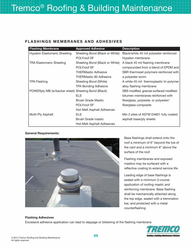
33
f l a s H I n G s m e m b R a n e s a n d a d H e s I V e s
flashing membrane approved adhesive description
Hypalon Elastomeric Sheeting Sheeting Bond (Black or White) Black/white 45 mil polyester reinforced
POLYroof SF Hypalon membrane
TRA Elastomeric Sheeting Sheeting Bond (Black or White) A black 45 mil flashing membrane
POLYroof SF compounded from a blend of EPDM and
THERMastic Adhesive SBR thermoset polymers reinforced with
THERMastic 80 Adhesive a polyester scrim
TPA Flashing Sheeting Bond (White) A white 45 mil thermoplastic tri-polymer
TPA Bonding Adhesive alloy flashing membrane
POWERply MB (w/backer sheet) Sheeting Bond (Black) SBS modified, granule surfaced modified-
ELS bitumen membranes reinforced with
Brush Grade Mastic fiberglass, polyester, or polyester/
POLYroof SF fiberglass composite
Hot-Melt Asphalt Adhesives
Multi-Ply Asphalt ELS Min 2 plies of ASTM D4601 fully coated
Brush Grade mastic asphalt base/ply sheets
Hot-Melt Asphalt Adhesives
General Requirements:
Base flashings shall extend onto the
roof a minimum of 6” beyond the toe of
the cant and a minimum 8” above the
surface of the roof.
Flashing membranes and exposed
mastics may be surfaced with a
reflective coating to extend service life.
Leading edge of base flashings is
sealed with a minimum 3-course
application of roofing mastic and
reinforcing membrane. Base flashing
shall be mechanically attached along
the top edge, sealed with a tremination
bar, and protected with a metal
counterflashing
flashing adhesives
Excessive adhesive application can lead to slippage or blistering of the flashing membrane.
Tremco® Roofing & Building Maintenance
© 2014 Tremco Roofing and Building MaintenanceAll rights reserved

Tremco® Roofing & Building Maintenance
34
Hypalon flashings shall be adhered with Sheeting Bond or POLYroof SF only.
TRA flashings may be adhered with Sheeting Bond, POLYroof SF, or SEBS modified hot melts (THERMastic or
THERMastic 80). Do not adhere with ASTM D312 Type III or IV non-modified asphalt.
Sheeting Bond shall be allowed 10-15 minutes open time for solvents to flash-off. Install Elastomeric flashing
sheets promptly after open time. Do not exceed open time or adhesive may skin-over and not bond properly.
flashing Installation – General
Flashing a roof requires traffic on the new roof installation to complete the flashings. On a THERM hot-applied
BUR the roof must be allowed to cool before the flashings are completed.
Protect POWERply roof membrane during the installation of the flashings. Plywood or insulation boards over
the roof membrane will spread loads over the surface and prevent point load damage to the membrane.
Temporary flashing may be installed during the membrane application with permanent flashings installed after
the cold adhesive has set and is less susceptible to displacement and damage.
Elastomeric flashings may be pre-hung and dropped into place to reduce the amount of traffic on the newly
installed roof.
Install base flashing over cant strips and other sloping and vertical surfaces, at roof edges, and at penetrations
through roof, and adhere to substrate.
Prime substrate with specified asphalt primer when adhering flashings in asphalt mastics or hot asphalt
adhesives.
Backer Sheet Application: Adhere backer sheet to substrate in cold-applied flashing adhesive or hot asphalt
adhesive.
Flashing Sheet Application: Adhere flashing sheet to backer sheet or substrate in specified cold-applied or hot-
melt adhesive.
Extend base flashing up walls or parapets a minimum of 8 inches above built-up roofing and 6 inches onto
field of built-up roofing.
Mechanically fasten top of base flashing securely at terminations and perimeter of roofing.
Seal top termination of base flashing with a metal termination bar.Install stripping where metal flanges and
edgings are set on roof membrane.
Flashing-Sheet Stripping: Install flashing-sheet stripping in a continuous layer of flashing sheet adhesive, and
extend onto roofing membrane.
Roof Drains: Set lead or copper flashing in bed of asphalt mastic on completed built-up roofing. Cover metal
© 2014 Tremco Roofing and Building MaintenanceAll rights reserved

35
flashing with stripping and extend a minimum of 6 inches beyond edge of metal flashing onto field of built-up
roofing. Clamp built-up roofing, metal flashing, and stripping into roof-drain clamping ring.
Hypalon flashing Installation:
Hypalon membrane Installation
Plan installation of Hypalon flashings so that the sheet extends 6” from the base of the cant onto the surface of
the roof system.
Remove embedded gravel, dirt, dust, rotted felt, and foreign matter. Priming is recommended.
Apply Sheeting Bond in a uniform and continuous application 1/16” thick to prepared area. Leave Sheeting
Bond exposed 15 minutes minimum before membrane application. Adjust open time depending on ambient
conditions.
Adhere Hypalon Elastomeric Sheeting in Sheeting Bond without wrinkles or voids. Using a steel hand roller,
apply consistent pressure to achieve full adhesion of the sheet to the flashing substrate. Sheeting must fully
conform to all angle changes, with no bridging or voids.
Vertical seams must be a minimum 4”. Strip in base of flashing membrane to roof with BURmesh reinforcing
fabric embedded in a base course of Sheeting Bond and covered with POLYroof LV, POLYroof SF, or ELS.
Exposed mastics used to strip in flashings may be covered with a reflective coating to extend service life.
Secure top edge of Hypalon flashing to wall by nailing on 6'' (152mm) centers or by using a termination bar
fastened on 8'' (203mm) centers.
Extend flood coat or surfacing emulsion over stripping plies and Hypalon Elastomeric Sheeting to the base of
the cant.
Hypalon seam Installation with sheeting bond
Wipe min. 4” wide lap seams with Tremco approved solvent, such as Toluene.
Fabricate laps with Sheeting Bond applied to one surface at 30-35 ft2 per gallon and allow approx. 15 minutes
open time for the solvents to flash off. Adjust open time depending on ambient conditions.
Join laps by pressing across fabricated lap seam; remove wrinkles/entrapped air; ensure positive contact. Roll
across laps with steel roller to ensure positive contact.
Strip in vertical seams and base of flashing membrane to roof with BURmesh reinforcing fabric embedded in a
base course of Sheeting Bond and covered with POLYroof LV or POLYroof SF. Allow the Sheeting Bond to
develop a firm set prior to the application of the POLYroof LV or SF.
TRa flashing Installation
Surface Preparation: Remove all dirt, dust, and other loose debris from the roof. Spud back all embedded
gravel from the area. Area should be prepared down to a clean, sound, dry base.
Tremco® Roofing & Building Maintenance
© 2014 Tremco Roofing and Building MaintenanceAll rights reserved

Tremco® Roofing & Building Maintenance
36
Plan installation of TRA Elastomeric Sheeting so flashing height is between 8'' and 12'' off the roof membrane
and the sheeting extends 6'' (152mm) from the base of the cant onto the roof system.
All vertical end laps shall be overlapped a minimum 4''.
Hot (sebs modified asphalt) application:
For hot application, apply THERMastic or THERMastic 80 SEBS-modified hot-melt adhesive to the area in a
uniform and continuous mopping at a coverage rate of 25 lbs. /SQ. Do not adhere TRA in ASTM D312 Type III
or IV asphalt.
Immediately embed TRA Elastomeric Sheeting in the hot application of approved adhesive.
Apply consistent pressure to the TRA Elastomeric Sheeting to achieve full adhesion of the sheet to the flashing
substrate. Sheeting must fully conform to all angle changes, with no bridging or voids.
Secure top edge of TRA Elastomeric Sheeting to wall by nailing on 6'' (152mm) centers or by using a
termination bar fastened on 8'' (203mm) centers.
Strip in base of flashing to roof system using a three course application of approved adhesive and
6''PolyTHERM roofing felt. As an alternate, strip in base of flashing with a five course stripping of approved
adhesive and THERMglass Roofing Ply.
Strip in vertical flashing laps with BURmesh set in Sheeting Bond, followed by a top course of POLYroof LV or
POLYroof SF.
Exposed mastics used to strip in flashings may be covered with a reflective coating to extend service life.
Cold adhesive application:
For cold application, apply Sheeting Bond or POLYroof SF to the area in a uniform and continuous layer at a
coverage rate of approx. 15 ft2/gal.
Leave Sheeting Bond exposed 15 minutes minimum prior to membrane application. Adjust open time
depending on ambient conditions.
Adhere TRA Elastomeric Sheeting in flashing adhesive. Apply consistent pressure to achieve full adhesion of
the sheet to the flashing substrate. Sheeting must fully conform to all angle changes, with no bridging or voids.
Secure top edge of TRA Elastomeric Sheeting to wall by nailing on 6'' (152mm) centers or by using a
termination bar fastened on 8'' (203mm) centers.
Strip in base of flashing to roof system and vertical flashing laps, using a three course application ofBURmesh
set in Sheeting Bond, followed by POLYroof LV or POLYroof SF. Exposed mastics may be covered with a
reflective coating to extend service life.
© 2014 Tremco Roofing and Building MaintenanceAll rights reserved

37
CoVeRaGe RaTes:
THeRmastic and THeRmastic 80: 25 lbs. /SQ.
flashing adhesive: 15 sq. ft. /gal Coverage rates will vary depending on ambient temperature and surface
conditions.
surfacing: TRA Elastomeric Sheeting may be coated with a reflective roof coating. Two coats are
recommended for best coverage. A STAIN-BLOCKING COATING OR PRIMER IS REQUIRED PRIOR TO
APPLYING WATERBASED ACRYLIC COATINGS TO TRA ELASTOMERIC SHEETING.
TPa flashing Installation:
application as Roof flashings for mb systems:
Plan installation of TPA Flashing Membrane so flashing extends 6” from the base of the cant onto the roof
system. All vertical overlaps must be 4” minimum.
Remove embedded gravel, dirt, dust, deteriorated felts, and other loose debris from the roof.
Spud back all embedded gravel from the area to receive the flashing and stripping. Area should be prepared
down to a clean, sound, dry base.
Apply adhesive to prepared area. Trowel apply White Sheeting Bond in a uniform and continuous application
1/16” thick to prepared flashing substrate. Allow Sheeting Bond to remain exposed for 15 minutes prior to
installing TPA Flashing Membrane into this adhesive. Adjust open time depending on ambient conditions.
Alternately, TPA Bonding Adhesive LV may be used to adhere TPA Flashings to the wall and out onto the roof
membrane. Apply adhesive to the back of the TPA Flashing and onto the substrate, in a contact cement
application.
Adhere TPA Flashing Membrane in adhesive, using care to avoid wrinkles and voids. Use a steel hand roller to
apply consistent pressure to achieve full adhesion of the membrane to the flashing substrate. TPA Flashing
Membrane must fully conform to all angle changes, with no bridging or voids.
Overlap vertical flashing seams a minimum of 4”. Heat weld vertical overlap seams, minimum width of 2”. Prior
to hot air heat welding, make sure lap interface materials are clean of dirt and moisture.
Seal inside and outside corners using Non-Reinforced TPA Membrane or TPA Inside/ Outside Corners applied
by hot air heat welding.
Strip in base of TPA Flashing Membrane with a first course of Rock-It Adhesive followed by a stripping ply of
BURmesh or PermaFab Polyester Reinforcing Fabric. Top dress these stripping courses with specified roof
surfacing, such as the Rock-It Surfacing System, Flood and Gravel, TremLastic SP and granules, or ICE
Coating.
No additional coatings are necessary for TPA Flashing Membrane. If a protective coating is required, special
Tremco® Roofing & Building Maintenance
© 2014 Tremco Roofing and Building MaintenanceAll rights reserved
Tremco® Roofing & Building Maintenance
38
surface preparation may be necessary. Tremco SP Primer is required prior to application of ICE Coating,
Solargard 6083, and Polarcote FR. Allow TPA Flashing Membrane to be exposed to the elements for 30 days
minimum prior to application of the Geogard Coating System.
PoWeRply mb flashing Installation
Surface Preparation: Remove all dirt, dust, and other loose debris from the roof. Spud back all embedded
gravel from the area. Area should be prepared down to a clean, sound, dry base.
Plan installation of POWERply MB membrane so flashing height is between 8'' and 12'' off the roof membrane
and the sheeting extends 6'' (152mm) from the base of the cant onto the roof system.
All vertical end laps shall be overlapped a minimum 4''.
A fully-coated backer sheet must be installed prior to the application of POWERply MB flashing.
POWERply MB Flashing which are up to 12” in flashing height may be installed in 10’ runs. POWERply MB
Flashings in excess of 12” in height must be installed in 3’ (1 meter) roll widths.
Hot asphalt application:
For hot application, apply approved hot-melt adhesive to the substrate area in a uniform and continuous
mopping at a coverage rate of 25 lbs. /SQ.
Immediately embed the backer sheet or POWERply membrane in the fluid hot adhesive. Apply consistent
pressure to achieve full adhesion of the sheet to the flashing substrate. Sheeting must fully conform to all angle
changes, with no bridging or voids.
Secure top edge of POWERply membrane to wall by nailing on 6'' (152mm) centers or by using a termination
bar fastened on 8'' (203mm) centers.
Strip in base of flashing to roof system using a three course application of approved adhesive and
6''PolyTHERM roofing felt or a five course application of approved adhesive and THERMglass Roofing Ply.
As an alternate, Strip in base of flashing to roof system using a minimum three course application of ELS
mastic and BURmesh.
Strip in vertical flashing laps with a minimum 3-course application of BURmesh set in ELS, Brush Grade
Mastic, POLYroof LV or POLYroof SF. Exposed mastics may be covered with a reflective coating to extend
service life.
Cold adhesive application:
For cold application, apply ELS, Brush Grade Mastic, Sheeting Bond (Black) or POLYroof SF to the area in a
uniform and continuous layer at a coverage rate of approx. 15 ft2/gal.
© 2014 Tremco Roofing and Building MaintenanceAll rights reserved

39
Leave Sheeting Bond exposed 15 minutes minimum prior to membrane application. Adjust open time
depending on ambient conditions.
Adhere the backer sheet and POWERply MB in flashing adhesive. Apply consistent pressure to achieve full
adhesion of the sheet to the flashing substrate. Sheeting must fully conform to all angle changes, with no
bridging or voids.
Secure top edge of POWERply MB membrane to wall by nailing on 6'' (152mm) centers or by using a
termination bar fastened on 8'' (203mm) centers.
Strip in base of flashing to roof system and vertical flashing laps, using a three course application of BURmesh
set in ELS, Brush Grade Mastic, POLYroof LV or POLYroof SF.
Stripping of POWERply MB flashing membrane may be eliminated only when POWERply MB Flashing is
heat welded to the POWERply MB roof membrane substrate.
surfacing: POWERply MB flashings may be coated with a reflective roof coating.
multi-Ply asphalt flashings
Multi-ply asphalt flashings consist of 2 plies of a fully-coated base/ply sheet such as BURmastic Composite
Ply HT or POWERply Base Sheet adhered with approved hot or cold applied adhesive. Type IV and VI
fiberglass felts are not approved for use in multi-ply asphalt flashing systems.
Surface Preparation: Remove all dirt, dust, and other loose debris from the roof. Spud back all embedded
gravel from the area. Area should be prepared down to a clean, sound, dry base.
Plan installation of multi-ply asphalt flashings so that flashing height is between 8'' and 12'' off the roof
membrane and the sheeting extends 6'' (152mm) from the base of the cant onto the roof system.
All vertical laps shall be overlapped a minimum 4''.
Hot asphalt application:
For hot application, apply approved hot-melt adhesive to the substrate area in a uniform and continuous
mopping at a coverage rate of 25 lbs. /SQ.
Immediately embed the backer sheet and flashing membrane in the fluid hot adhesive. Apply consistent
pressure to achieve full adhesion of the sheet to the flashing substrate. Sheeting must fully conform to all angle
changes, with no bridging or voids.
Secure top edge of multi-ply flashing to wall by nailing on 6'' (152mm) centers or by using a termination bar
fastened on 8'' (203mm) centers.
Strip in base of flashing to roof system using a three course application of approved adhesive and
6''PolyTHERM roofing felt or a five course application of approved adhesive and THERMglass Roofing Ply.
Tremco® Roofing & Building Maintenance
© 2014 Tremco Roofing and Building MaintenanceAll rights reserved

Tremco® Roofing & Building Maintenance
40
As an alternate, Strip in base of flashing to roof system using a minimum three course application of ELS
mastic and BURmesh.
Strip in vertical flashing laps with a minimum 3-course application of BURmesh set in ELS, Brush Grade
Mastic, POLYroof LV or POLYroof SF. Exposed mastics may be covered with a reflective coating to extend
service life.
Cold adhesive application:
For cold application, apply ELS, Brush Grade Mastic, Sheeting Bond (Black) or POLYroof SF to the area in a
uniform and continuous layer at a coverage rate of approx. 15 ft2/gal.
Leave Sheeting Bond exposed 15 minutes minimum prior to membrane application. Adjust open time
depending on ambient conditions.
Adhere the backer sheet and flashing membrane in flashing adhesive. Apply consistent pressure to achieve full
adhesion of the sheet to the flashing substrate. Sheeting must fully conform to all angle changes, with no
bridging or voids.
Secure top edge of multi-ply flashing to wall by nailing on 6'' (152mm) centers or by using a termination bar
fastened on 8'' (203mm) centers.
Strip in base of flashing to roof system and vertical flashing laps, using a three course application of BURmesh
set in ELS, Brush Grade Mastic, POLYroof LV or POLYroof SF.
surfacing: Multi-ply asphalt flashings require the application of a reflective coating. Two coats are
recommended for best coverage.
© 2014 Tremco Roofing and Building MaintenanceAll rights reserved
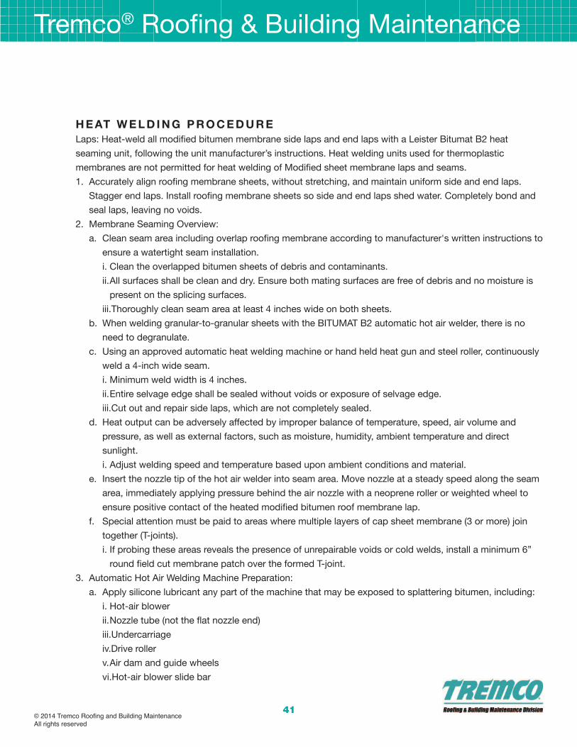
41
H e aT W e l d I n G P R o C e d u R e
Laps: Heat-weld all modified bitumen membrane side laps and end laps with a Leister Bitumat B2 heat
seaming unit, following the unit manufacturer’s instructions. Heat welding units used for thermoplastic
membranes are not permitted for heat welding of Modified sheet membrane laps and seams.
1. Accurately align roofing membrane sheets, without stretching, and maintain uniform side and end laps.
Stagger end laps. Install roofing membrane sheets so side and end laps shed water. Completely bond and
seal laps, leaving no voids.
2. Membrane Seaming Overview:
a. Clean seam area including overlap roofing membrane according to manufacturer's written instructions to
ensure a watertight seam installation.
i. Clean the overlapped bitumen sheets of debris and contaminants.
ii.All surfaces shall be clean and dry. Ensure both mating surfaces are free of debris and no moisture is
present on the splicing surfaces.
iii.Thoroughly clean seam area at least 4 inches wide on both sheets.
b. When welding granular-to-granular sheets with the BITUMAT B2 automatic hot air welder, there is no
need to degranulate.
c. Using an approved automatic heat welding machine or hand held heat gun and steel roller, continuously
weld a 4-inch wide seam.
i. Minimum weld width is 4 inches.
ii.Entire selvage edge shall be sealed without voids or exposure of selvage edge.
iii.Cut out and repair side laps, which are not completely sealed.
d. Heat output can be adversely affected by improper balance of temperature, speed, air volume and
pressure, as well as external factors, such as moisture, humidity, ambient temperature and direct
sunlight.
i. Adjust welding speed and temperature based upon ambient conditions and material.
e. Insert the nozzle tip of the hot air welder into seam area. Move nozzle at a steady speed along the seam
area, immediately applying pressure behind the air nozzle with a neoprene roller or weighted wheel to
ensure positive contact of the heated modified bitumen roof membrane lap.
f. Special attention must be paid to areas where multiple layers of cap sheet membrane (3 or more) join
together (T-joints).
i. If probing these areas reveals the presence of unrepairable voids or cold welds, install a minimum 6”
round field cut membrane patch over the formed T-joint.
3. Automatic Hot Air Welding Machine Preparation:
a. Apply silicone lubricant any part of the machine that may be exposed to splattering bitumen, including:
i. Hot-air blower
ii.Nozzle tube (not the flat nozzle end)
iii.Undercarriage
iv.Drive roller
v.Air dam and guide wheels
vi.Hot-air blower slide bar
Tremco® Roofing & Building Maintenance
© 2014 Tremco Roofing and Building MaintenanceAll rights reserved

Tremco® Roofing & Building Maintenance
42
b. This silicone will serve as a buffer between the melted bitumen and the machine’s surfaces, making it
easier to clean. Make sure to complete lubrication step before turning the machine on, as aerosol spray
may be combustible.
c. Plug the power cord into the power source outlet. Snap the cord clip onto the cord holder to ensure the
cord doesn’t get entangled in the machine.
d. Turn the machine on with the power switch. Using the temperature, speed and air volume dials;
configure the heat welding machine according to the job’s requirements.
e. After the welder has warmed up, run a test weld on scrap material to make sure the temperature, speed
and air-volume settings are properly configured for the job. If the test weld fails, make any necessary
adjustments to the machine’s settings before moving on.
4. Test Weld for Automatic Hot Air Welding Machine:
a. To ensure proper heat output, perform a test weld on scrap material to make sure the proper settings are
in place. To perform a test weld:
i. Cut two, 10-foot long strips of cap ply sheeting.
ii.With the configured and warmed-up automatic hot air welder, weld the two strips together.
iii.A good weld should produce a bead of bitumen along the edge of the seam.
iv.Using a hook-blade, cut three-to-five 2-inch strips perpendicular to the seam. Strips should be cut
from the beginning, middle and end of the test weld to ensure quality throughout.
v.As soon as the bitumen surface over the seam weld is the same temperature as the rest of the material
surface, tear the strips apart. A quality weld should reveal the scrim, or netting, of the bitumen material.
5. Automatic Hot Air Welding Machine Operation:
a. When the test weld is approved, position your properly configured automatic heat welding machine on
top of the cap ply seam.
b. Swing the guide roller down and align it with the seam edge.
i. Align the drive roller with the seam edge, but place it approximately 3/8-inch off the edge. This will help
to keep the roller clean.
c. Stand in the welding position behind the welding machine with the guide bar directly in front of you.
d. Engage the lifting device by pushing the handle away from you. This will pick the drive roller up off the
bitumen sheet.
e. Turn on the drive switch to start the drive roller. The machine will not begin moving as long as the lifting
wheel is engaged.
f. Pull up on the locking lever, lower the hot-air blower, and slide the nozzle between the overlapped
bitumen.
g. Count to three and then pull back on the lifting wheel lever. The machine will begin moving right away, so
make sure to have a firm grip on the guide bar.
h. Guide the heat welding machine along the seam edge using the guide bar.
i. Do not push or pull the machine. Simply steer it so the guide roller tracks the seam edge.
ii.Remember to keep the drive roller approximately 3/8-inch off the seam edge to avoid melted bitumen
sticking to it.
© 2014 Tremco Roofing and Building MaintenanceAll rights reserved

43
iii.Keep the nozzle completely between the overlapped bitumen. If the nozzle’s air holes are exposed
they will spray melted bitumen on the machine, material surface, and potentially your clothes and skin.
i. At the end of the weld, immediately pull up on the locking lever, slide the hot-air blower away from the
machine and then swivel it up into locked position.
j. Press in the drive switch to stop the drive roller and remove welder from seam area. Where needed,
complete welding process using a hand held heat gun.
k. Refer to manufacturer’s approved automatic heat welding machine or hand held heat gun operating
guide for detailed application instructions.
6. Test lap edges with probe to verify seam weld continuity.
a. All welded seams must be manually checked for voids or seal deficiencies by probing the entire seam
area with a dull cotter key extractor after the seam has cooled. Properly constructed laps will not
separate at the lap interface when tested.
b. In addition, destructive testing may be required at the beginning of every workday and every time there
is an interruption in the welding process (i.e. Power failure, welder shut down and job site conditions
change). Test cut and all deficiencies must be repaired immediately
c. Repair tears, voids and lapped seams in roofing membrane that do not meet requirements listed above.
Tremco® Roofing & Building Maintenance
© 2014 Tremco Roofing and Building MaintenanceAll rights reserved
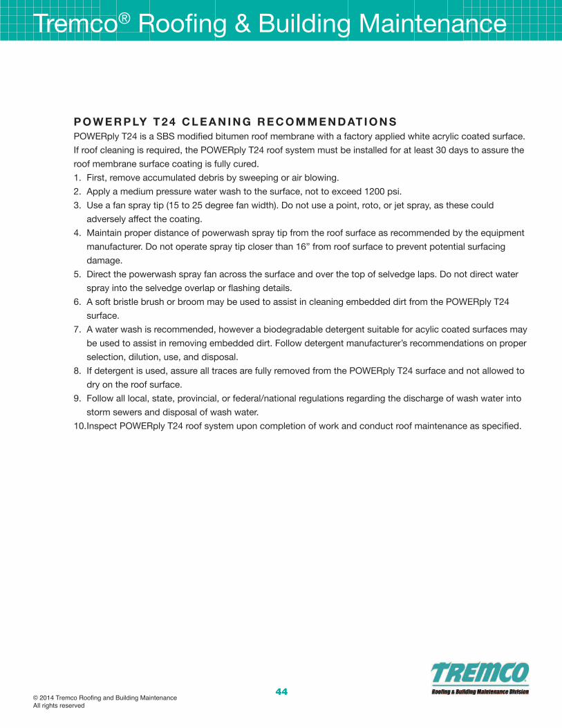
Tremco® Roofing & Building Maintenance
44
P o W e R P lY T 2 4 C l e a n I n G R e C o m m e n d aT I o n s
POWERply T24 is a SBS modified bitumen roof membrane with a factory applied white acrylic coated surface.
If roof cleaning is required, the POWERply T24 roof system must be installed for at least 30 days to assure the
roof membrane surface coating is fully cured.
1. First, remove accumulated debris by sweeping or air blowing.
2. Apply a medium pressure water wash to the surface, not to exceed 1200 psi.
3. Use a fan spray tip (15 to 25 degree fan width). Do not use a point, roto, or jet spray, as these could
adversely affect the coating.
4. Maintain proper distance of powerwash spray tip from the roof surface as recommended by the equipment
manufacturer. Do not operate spray tip closer than 16” from roof surface to prevent potential surfacing
damage.
5. Direct the powerwash spray fan across the surface and over the top of selvedge laps. Do not direct water
spray into the selvedge overlap or flashing details.
6. A soft bristle brush or broom may be used to assist in cleaning embedded dirt from the POWERply T24
surface.
7. A water wash is recommended, however a biodegradable detergent suitable for acylic coated surfaces may
be used to assist in removing embedded dirt. Follow detergent manufacturer’s recommendations on proper
selection, dilution, use, and disposal.
8. If detergent is used, assure all traces are fully removed from the POWERply T24 surface and not allowed to
dry on the roof surface.
9. Follow all local, state, provincial, or federal/national regulations regarding the discharge of wash water into
storm sewers and disposal of wash water.
10.Inspect POWERply T24 roof system upon completion of work and conduct roof maintenance as specified.
© 2014 Tremco Roofing and Building MaintenanceAll rights reserved
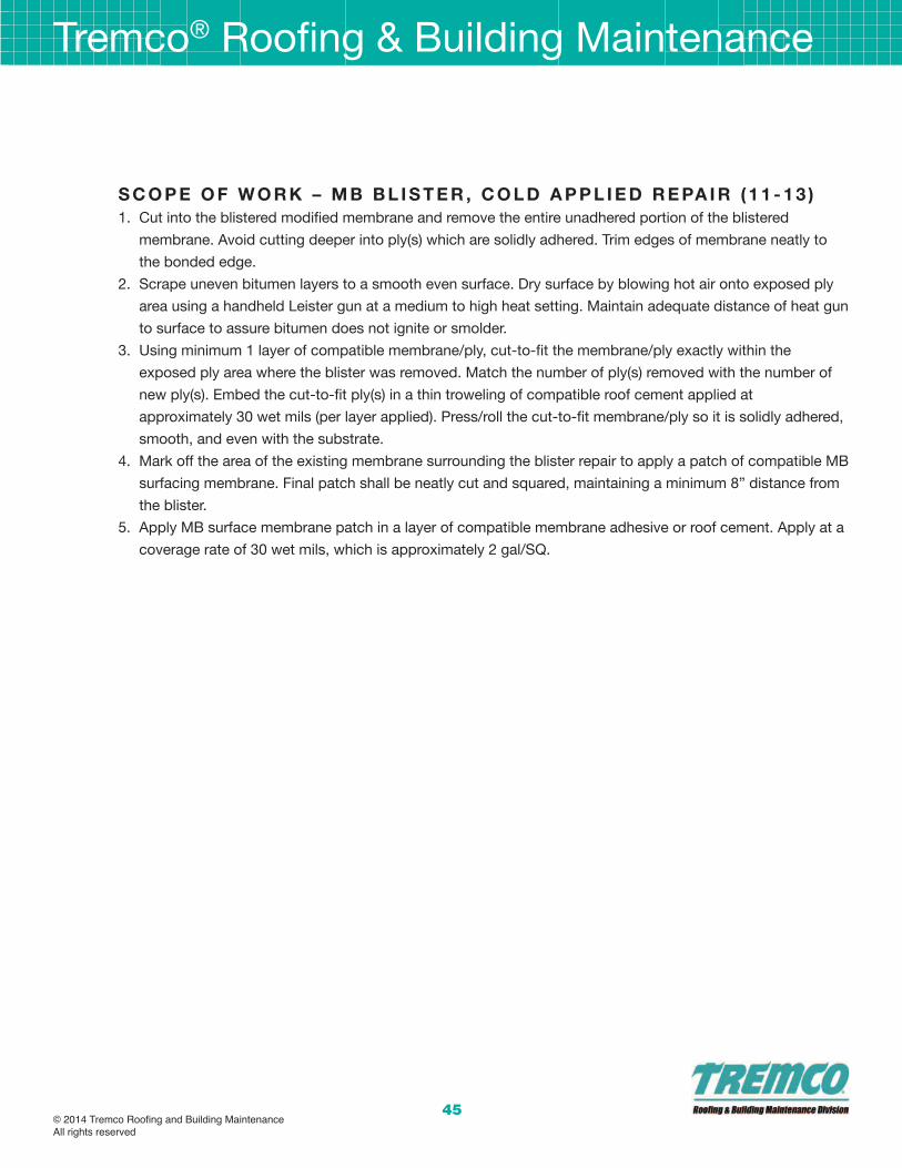
45
s C o P e o f W o R k – m b b l I s T e R , C o l d a P P l I e d R e Pa I R ( 1 1 - 1 3 )
1. Cut into the blistered modified membrane and remove the entire unadhered portion of the blistered
membrane. Avoid cutting deeper into ply(s) which are solidly adhered. Trim edges of membrane neatly to
the bonded edge.
2. Scrape uneven bitumen layers to a smooth even surface. Dry surface by blowing hot air onto exposed ply
area using a handheld Leister gun at a medium to high heat setting. Maintain adequate distance of heat gun
to surface to assure bitumen does not ignite or smolder.
3. Using minimum 1 layer of compatible membrane/ply, cut-to-fit the membrane/ply exactly within the
exposed ply area where the blister was removed. Match the number of ply(s) removed with the number of
new ply(s). Embed the cut-to-fit ply(s) in a thin troweling of compatible roof cement applied at
approximately 30 wet mils (per layer applied). Press/roll the cut-to-fit membrane/ply so it is solidly adhered,
smooth, and even with the substrate.
4. Mark off the area of the existing membrane surrounding the blister repair to apply a patch of compatible MB
surfacing membrane. Final patch shall be neatly cut and squared, maintaining a minimum 8” distance from
the blister.
5. Apply MB surface membrane patch in a layer of compatible membrane adhesive or roof cement. Apply at a
coverage rate of 30 wet mils, which is approximately 2 gal/SQ.
Tremco® Roofing & Building Maintenance
© 2014 Tremco Roofing and Building MaintenanceAll rights reserved

Tremco® Roofing & Building Maintenance
46
s C o P e o f W o R k ; m b b l I s T e R – T o R C H R e Pa I R :
1. Cut and remove the entire unadhered part of the modified bitumen cap membrane. Do not extend cut into
base membrane which are solidly adhered.
2. Trim and reset POWERply membrane to fit in cutout. Assure exposed ply area is fully dry, then heat weld
exiting MB cutout back into place.
3. Heat weld torch grade POWERply MB over blister cutout. Assure topping membrane is neatly squared off.
Dimensions shall extend a minimum 6” beyond repair in each direction.
© 2014 Tremco Roofing and Building MaintenanceAll rights reserved

47
s e a m R e Pa I R o n P o W e R P lY / P o W e R P lY T 2 4 :
materials:
• Permafab Polyester
• alphaGuard mT Top Coat – White
1. Assure substrate areas where material will be applied is clean and dry.
2. Cut out and remove loose and curled roof membrane and/or existing coating to assure a flat substrate.
3. Apply AlphaGuard MT Top Coat (White) at 20 to 25 wet mils (approx. 1.5 gal/SQ) in a 5” wide pass centered
over the area to be repaired.
4. Set PermaFab into wet AlphaGuard MT Top Coat. Do not allow first layer of AlphaGuard MT to skin or cure
prior to application of PermaFab.
5. Apply AlphaGuard MT Top Coat (White) over freshly applied PermaFab at 20 to 25 wet mils (approx. 1.5
gal/SQ) while applying tension and pressure to PermaFab.
6. Assure PermaFab polyester is fully saturated with AlphaGuard MT Top Coat and flat to the substrate
without voids underneath.
7. Allow materials to cure 24 hours prior to opening area to foot traffic.
Tremco® Roofing & Building Maintenance
© 2014 Tremco Roofing and Building MaintenanceAll rights reserved
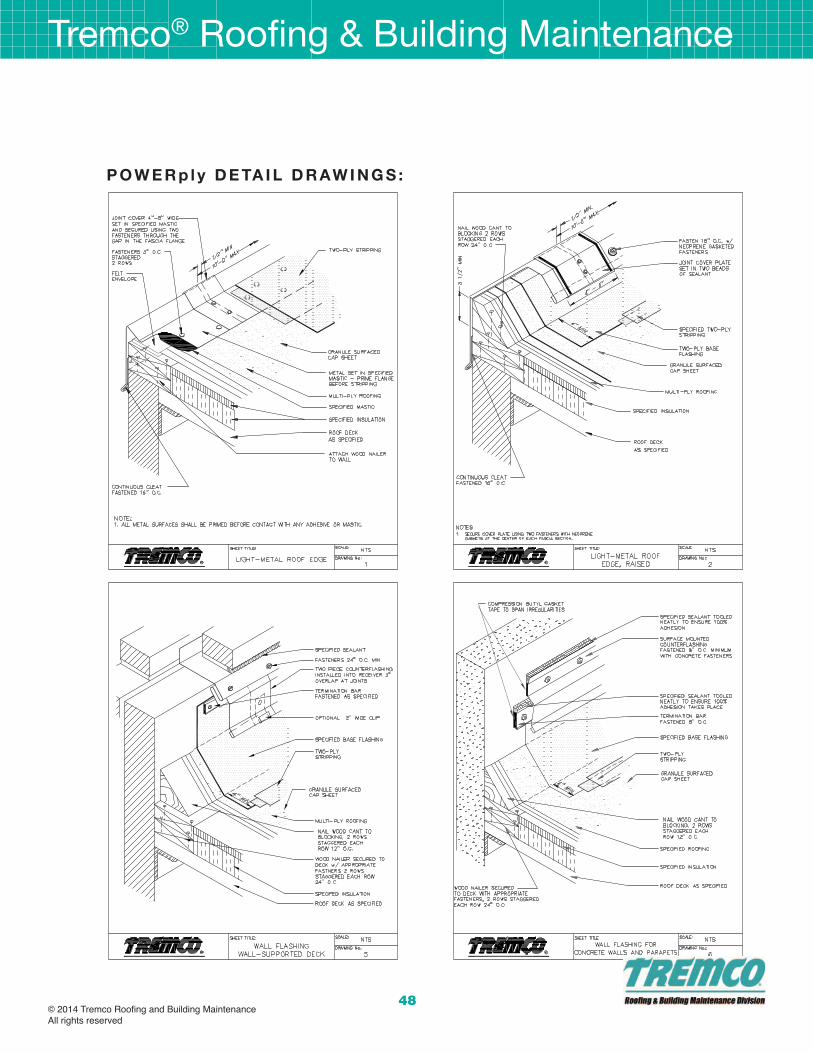
Tremco® Roofing & Building Maintenance
48
P o W e R p l y d e Ta I l d R aW I n G s :
© 2014 Tremco Roofing and Building MaintenanceAll rights reserved

49
P o W e R p l y d e Ta I l d R aW I n G s :
Tremco® Roofing & Building Maintenance
© 2014 Tremco Roofing and Building MaintenanceAll rights reserved

Tremco® Roofing & Building Maintenance
50
P o W e R p l y d e Ta I l d R aW I n G s :
© 2014 Tremco Roofing and Building MaintenanceAll rights reserved
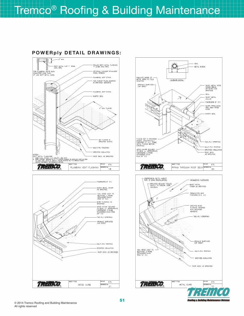
51
P o W e R p l y d e Ta I l d R aW I n G s :
Tremco® Roofing & Building Maintenance
© 2014 Tremco Roofing and Building MaintenanceAll rights reserved
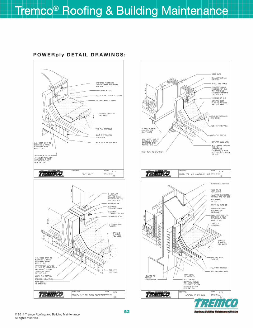
Tremco® Roofing & Building Maintenance
52
Tremco® Roofing & Building Maintenance
P o W e R p l y d e Ta I l d R aW I n G s :
© 2014 Tremco Roofing and Building MaintenanceAll rights reserved

53
P o W e R p l y d e Ta I l d R aW I n G s :
Tremco® Roofing & Building Maintenance
© 2014 Tremco Roofing and Building MaintenanceAll rights reserved

PO
WE
Rp
lyTremco® Roofing & Building Maintenance
3735 Green Road • Beachwood, Ohio 44122216.292.5000 • www.tremcoroofing.com
© 2014 Tremco Roofing and Building MaintenanceAll rights reserved