t24 telemetry user manual - novatech loadcells€¦ · product quick locator ... configuration ......
TRANSCRIPT
T24 Telemetry User Manual
mantracourt.com
T24 Wireless Telemetry
Mantracourt Electronics Limited T24 Telemetry User Manual 1
Introduction / Overview .......................................................................................................................................... 16 Navigating This Manual .......................................................................................................................................... 16 Product Quick Locator ............................................................................................................................................. 16 T24 Telemetry Basic Principles............................................................................................................................... 17
Transmitters & Receivers ...................................................................................................................................................................... 17 Transmitters ........................................................................................................................................................................................... 17 Receivers ................................................................................................................................................................................................. 17
Radio Channel and Group Key ........................................................................................................................................................... 17 Radio Channel ...................................................................................................................................................................................... 17 Group Key ............................................................................................................................................................................................... 17
Configuring Multiple Modules to Use the Same Radio Settings .......................................................................................... 18 ID and Data Tags ...................................................................................................................................................................................... 18 Transmitter Module Modes of Operation ...................................................................................................................................... 18
Normal ..................................................................................................................................................................................................... 18 Configuration ........................................................................................................................................................................................ 18 Sleep ......................................................................................................................................................................................................... 18
Transmitter Module Sleep Delay Settings ...................................................................................................................................... 19 Pairing .......................................................................................................................................................................................................... 19
Pairing From T24 Toolkit .................................................................................................................................................................. 19 Pairing From a Receiver Module ................................................................................................................................................... 19
Soft Pairing ................................................................................................................................................................................................. 20 Configuring an Attached Base Station ............................................................................................................................................ 20 Asynchronous Operation and Logging ........................................................................................................................................... 20 Bandwidth ................................................................................................................................................................................................... 21 Repeaters and Repeater Subgroups ................................................................................................................................................ 21
T24 Toolkit ................................................................................................................................................................ 22 Common Toolkit Pages ........................................................................................................................................... 23
Setup Base Station Communications ............................................................................................................................................... 23 Analyser ....................................................................................................................................................................................................... 24 Channel Monitor ...................................................................................................................................................................................... 25 Home ............................................................................................................................................................................................................ 27
Connecting to a remote module ................................................................................................................................................... 27 Connecting to the attached base station module ................................................................................................................. 28 Manual Connection ............................................................................................................................................................................ 28
Information ................................................................................................................................................................................................. 29 Battery and Radio Levels ....................................................................................................................................................................... 30 Battery and Radio Levels Advanced ................................................................................................................................................. 31 Radio Settings ........................................................................................................................................................................................... 32 Radio Settings Advanced ...................................................................................................................................................................... 33 Save and Restore ..................................................................................................................................................................................... 34
Transmitter Modules ............................................................................................................................................... 35 T24-ACM-SA, T24-ACMi-SA, T24-ACMm-SA, T24-SAe, T24-SAi .......................................................................................... 35
Overview ................................................................................................................................................................................................. 35 Order Codes .......................................................................................................................................................................................... 35
T24-SAe .............................................................................................................................................................................................. 35 T24-SAi ................................................................................................................................................................................................ 35 T24-ACM-SA ..................................................................................................................................................................................... 35 T24-ACMi-SA .................................................................................................................................................................................... 35 T24-ACMm-SA ................................................................................................................................................................................. 35
Connections ........................................................................................................................................................................................... 36 T24-SAe, T24-SAi ............................................................................................................................................................................ 36
Power .............................................................................................................................................................................................. 36 Sensor ............................................................................................................................................................................................. 36
T24-ACM-SA ..................................................................................................................................................................................... 37 Power .............................................................................................................................................................................................. 37 Sensor ............................................................................................................................................................................................. 37
Mantracourt Electronics Limited T24 Telemetry User Manual 2
T24-ACMi-SA .................................................................................................................................................................................... 38 Power .............................................................................................................................................................................................. 38 Sensor ............................................................................................................................................................................................. 38
T24-ACMm-SA ................................................................................................................................................................................. 39 Power .............................................................................................................................................................................................. 39
Connecting T24-BB1 ............................................................................................................................................................ 39 Sensor ............................................................................................................................................................................................. 39 Using Completion Resistors ................................................................................................................................................... 40
Full Bridge ............................................................................................................................................................................... 40 Half Bridge ............................................................................................................................................................................. 40 Quarter Bridge ........................................................................................................................................................................ 40
High Reference .................................................................................................................................................................. 40 Low Reference .................................................................................................................................................................... 40
Shield Connections (All Enclosures) .................................................................................................................................... 41 Configuration ........................................................................................................................................................................................ 42
Data Rates and Quality ................................................................................................................................................................. 42 Calibration ......................................................................................................................................................................................... 44 Calibration by Certificate ............................................................................................................................................................. 46 Calibration Advanced .................................................................................................................................................................... 47 Advanced Settings.......................................................................................................................................................................... 48
Enclosure & Mounting ...................................................................................................................................................................... 49 T24-SAe, T24-SAi ............................................................................................................................................................................ 49 T24-ACM-SA ..................................................................................................................................................................................... 49 T24-ACMi-SA .................................................................................................................................................................................... 49 T24-ACMm-SA ................................................................................................................................................................................. 49
Antennas ................................................................................................................................................................................................. 49 T24-SAi ................................................................................................................................................................................................ 49 T24-SAe .............................................................................................................................................................................................. 49 T24-ACM-SA, T24-ACMi-SA, T24-ACMm-SA ...................................................................................................................... 49
Specification .......................................................................................................................................................................................... 50 Radio Range ...................................................................................................................................................................................... 51
T24-ACM-SAf, T24-ACMi-SAf, T24-ACMm-SAf, T24-SAfe, T24-SAfi .................................................................................. 52 Overview ................................................................................................................................................................................................. 52 Order Codes .......................................................................................................................................................................................... 52
T24-SAfe ............................................................................................................................................................................................. 52 T24-SAfi .............................................................................................................................................................................................. 52 T24-ACM-SAf ................................................................................................................................................................................... 52 T24-ACMi-SAf .................................................................................................................................................................................. 52 T24-ACMm-SAf ............................................................................................................................................................................... 52
Connections ........................................................................................................................................................................................... 53 T24-SAfe, T24-SAfi ......................................................................................................................................................................... 53
Power .............................................................................................................................................................................................. 53 Sensor ............................................................................................................................................................................................. 53
T24-ACM-SAf ................................................................................................................................................................................... 54 Power .............................................................................................................................................................................................. 54 Sensor ............................................................................................................................................................................................. 54
T24-ACMi-SAf .................................................................................................................................................................................. 55 Power .............................................................................................................................................................................................. 55 Sensor ............................................................................................................................................................................................. 55
T24-ACMm-SAf ............................................................................................................................................................................... 56 Power .............................................................................................................................................................................................. 56 Connecting T24-BB1 ................................................................................................................................................................. 56 Sensor ............................................................................................................................................................................................. 56 Using Completion Resistors ................................................................................................................................................... 57
Full Bridge ............................................................................................................................................................................... 57 Half Bridge ............................................................................................................................................................................. 57
Mantracourt Electronics Limited T24 Telemetry User Manual 3
Quarter Bridge ........................................................................................................................................................................ 57 High Reference .................................................................................................................................................................. 57 Low Reference .................................................................................................................................................................... 57
Shield Connections (All Enclosures) .................................................................................................................................... 58 Configuration ........................................................................................................................................................................................ 59
Battery Life ......................................................................................................................................................................................... 59 Zero Settings .................................................................................................................................................................................... 61 Data Provider Monitor .................................................................................................................................................................. 62 Advanced Settings.......................................................................................................................................................................... 63
Enclosure & Mounting ...................................................................................................................................................................... 64 T24-SAfe, T24-SAfi ......................................................................................................................................................................... 64 T24-ACM-SAf ................................................................................................................................................................................... 64 T24-ACMi-SAf .................................................................................................................................................................................. 64 T24-ACMm-SAf ............................................................................................................................................................................... 64
Antennas ................................................................................................................................................................................................. 64 T24-SAfi .............................................................................................................................................................................................. 64 T24-SAfe ............................................................................................................................................................................................. 64 T24-ACM-SAf, T24-ACMi-SAf, T24-ACMm-SAf .................................................................................................................. 64
Specification .......................................................................................................................................................................................... 65 Radio Range ...................................................................................................................................................................................... 65
T24-ACM-VA, T24-ACMi-VA, T24-ACMm-VA, T24-VAe, T24-VAi ........................................................................................ 66 Overview ................................................................................................................................................................................................. 66 Order Codes .......................................................................................................................................................................................... 66
T24-VAe .............................................................................................................................................................................................. 66 T24-VAi ............................................................................................................................................................................................... 66 T24-ACM-VA .................................................................................................................................................................................... 66 T24-ACMi-VA ................................................................................................................................................................................... 66 T24-ACMm-VA ................................................................................................................................................................................ 66
Connections ........................................................................................................................................................................................... 67 T24-VAe, T24-VAi ........................................................................................................................................................................... 67
Power .............................................................................................................................................................................................. 67 Sensor ............................................................................................................................................................................................. 67
T24-ACM-VA .................................................................................................................................................................................... 68 Power .............................................................................................................................................................................................. 68 Sensor ............................................................................................................................................................................................. 68
T24-ACMi-VA ................................................................................................................................................................................... 69 Power .............................................................................................................................................................................................. 69 Sensor ............................................................................................................................................................................................. 69
T24-ACMm-VA ................................................................................................................................................................................ 70 Power .............................................................................................................................................................................................. 70
Connecting T24-BB1 ............................................................................................................................................................ 70 Sensor ............................................................................................................................................................................................. 70
Shield Connections (All Enclosures) ........................................................................................................................................ 71 Configuration ........................................................................................................................................................................................ 72
Data Rates and Quality ................................................................................................................................................................. 72 Calibration ......................................................................................................................................................................................... 74 Calibration by Certificate ............................................................................................................................................................. 76 Calibration Advanced .................................................................................................................................................................... 77 Advanced Settings.......................................................................................................................................................................... 78
Enclosure & Mounting ...................................................................................................................................................................... 79 T24-VAe, T24-VAi ........................................................................................................................................................................... 79 T24-ACM-VA .................................................................................................................................................................................... 79 T24-ACMi-VA ................................................................................................................................................................................... 79 T24-ACMm-VA ................................................................................................................................................................................ 79
Antennas ................................................................................................................................................................................................. 80 T24-VAi ............................................................................................................................................................................................... 80
Mantracourt Electronics Limited T24 Telemetry User Manual 4
T24-VAe .............................................................................................................................................................................................. 80 T24-ACM-VA, T24-ACMi-VA, T24-ACMm-VA ..................................................................................................................... 80
Specification .......................................................................................................................................................................................... 81 Radio Range ...................................................................................................................................................................................... 81
T24-ACM-IA, T24-ACMi-IA, T24-ACMm-IA, T24-IAe, T24-IAi ................................................................................................ 82 Overview ................................................................................................................................................................................................. 82 Order Codes .......................................................................................................................................................................................... 82
T24-IAe................................................................................................................................................................................................ 82 T24-IAi ................................................................................................................................................................................................. 82 T24-ACM-IA ...................................................................................................................................................................................... 82 T24-ACMi-IA ..................................................................................................................................................................................... 82 T24-ACMm-IA .................................................................................................................................................................................. 82
Connections ........................................................................................................................................................................................... 83 T24-IAe, T24-IAi ............................................................................................................................................................................... 83
Power .............................................................................................................................................................................................. 83 Sensor ............................................................................................................................................................................................. 83
T24-ACM-IA ...................................................................................................................................................................................... 83 Power .............................................................................................................................................................................................. 83 Sensor ............................................................................................................................................................................................. 84
T24-ACMi-IA ..................................................................................................................................................................................... 85 Power .............................................................................................................................................................................................. 85 Sensor ............................................................................................................................................................................................. 85
T24-ACMm-IA .................................................................................................................................................................................. 86 Power .............................................................................................................................................................................................. 86
Connecting T24-BB1 ............................................................................................................................................................ 86 Sensor ............................................................................................................................................................................................. 86
Shield Connections (All Enclosures) ........................................................................................................................................ 87 Configuration ........................................................................................................................................................................................ 88
Data Rates and Quality ................................................................................................................................................................. 88 Calibration ......................................................................................................................................................................................... 90 Calibration by Certificate ............................................................................................................................................................. 92 Calibration Advanced .................................................................................................................................................................... 93 Advanced Settings.......................................................................................................................................................................... 94
Enclosure & Mounting ...................................................................................................................................................................... 95 T24-IAe, T24-IAi ............................................................................................................................................................................... 95 T24-ACM-IA ...................................................................................................................................................................................... 95 T24-ACMi-IA ..................................................................................................................................................................................... 95 T24-ACMm-IA .................................................................................................................................................................................. 95
Antennas ................................................................................................................................................................................................. 96 T24-IAi ................................................................................................................................................................................................. 96 T24-IAe................................................................................................................................................................................................ 96 T24-ACM-IA, T24-ACMi-IA, T24-ACMm-IA .......................................................................................................................... 96
Specification .......................................................................................................................................................................................... 97 Radio Range ...................................................................................................................................................................................... 97
T24-ACM-TA, T24-ACMi-TA, T24-ACMm-TA, T24-TAe, T24-TAi .......................................................................................... 98 Overview ................................................................................................................................................................................................. 98 Order Codes .......................................................................................................................................................................................... 98
T24-TAe .............................................................................................................................................................................................. 98 T24-TAi ................................................................................................................................................................................................ 98 T24-ACM-TA ..................................................................................................................................................................................... 98 T24-ACMi-TA .................................................................................................................................................................................... 98 T24-ACMm-TA ................................................................................................................................................................................. 98
Connections ........................................................................................................................................................................................... 99 T24-TAe, T24-TAi ............................................................................................................................................................................ 99
Power .............................................................................................................................................................................................. 99 Sensor ............................................................................................................................................................................................. 99
Mantracourt Electronics Limited T24 Telemetry User Manual 5
2 Wire ......................................................................................................................................................................................... 99 3 Wire ......................................................................................................................................................................................... 99 4 Wire ....................................................................................................................................................................................... 100
T24-ACM-TA ................................................................................................................................................................................... 100 Power ............................................................................................................................................................................................ 100 Sensor ........................................................................................................................................................................................... 100
T24-ACMi-TA .................................................................................................................................................................................. 101 Power ............................................................................................................................................................................................ 101 Sensor ........................................................................................................................................................................................... 101
T24-ACMm-TA ............................................................................................................................................................................... 101 Power ............................................................................................................................................................................................ 101
Connecting T24-BB1 .......................................................................................................................................................... 102 Sensor ........................................................................................................................................................................................... 102
Shield Connections (All Enclosures) ...................................................................................................................................... 103 Configuration ...................................................................................................................................................................................... 104
Data Rates and Quality ............................................................................................................................................................... 104 Calibration ....................................................................................................................................................................................... 106 Advanced Settings........................................................................................................................................................................ 107
Enclosure & Mounting .................................................................................................................................................................... 108 T24-TAe, T24-TAi .......................................................................................................................................................................... 108 T24-ACM-TA ................................................................................................................................................................................... 108 T24-ACMi-TA .................................................................................................................................................................................. 108 T24-ACMm-TA ............................................................................................................................................................................... 108
Antennas ............................................................................................................................................................................................... 108 T24-TAi .............................................................................................................................................................................................. 108 T24-TAe ............................................................................................................................................................................................ 108 T24-ACM-TA, T24-ACMi-TA, T24-ACMm-TA .................................................................................................................... 108
Specification ........................................................................................................................................................................................ 109 Radio Range .................................................................................................................................................................................... 109
T24-ACM-RA, T24-ACMi-RA, T24-ACMm-RA, T24-RAe, T24RAi ........................................................................................ 110 Overview ............................................................................................................................................................................................... 110 Order Codes ........................................................................................................................................................................................ 110
T24-RAe ............................................................................................................................................................................................ 110 T24-RAi ............................................................................................................................................................................................. 110 T24-ACM-RA................................................................................................................................................................................... 110 T24-ACMi-RA ................................................................................................................................................................................. 110 T24-ACMm-RA............................................................................................................................................................................... 110
Connections ......................................................................................................................................................................................... 111 T24-RAe, T24-RAi.......................................................................................................................................................................... 111
Power ............................................................................................................................................................................................ 111 Sensor ........................................................................................................................................................................................... 111
T24-ACM-RA................................................................................................................................................................................... 111 Power ............................................................................................................................................................................................ 111 Sensor ........................................................................................................................................................................................... 112
T24-ACMi-RA ................................................................................................................................................................................. 113 Power ............................................................................................................................................................................................ 113 Sensor ........................................................................................................................................................................................... 113
T24-ACMm-RA............................................................................................................................................................................... 114 Power ............................................................................................................................................................................................ 114
Connecting T24-BB1 .......................................................................................................................................................... 114 Sensor ........................................................................................................................................................................................... 114
Shield Connections (All Enclosures) ...................................................................................................................................... 115 Configuration ...................................................................................................................................................................................... 116
Data Rates and Quality ............................................................................................................................................................... 116 Input / Output Configuration .................................................................................................................................................. 118 Calibration by Certificate ........................................................................................................................................................... 120
Mantracourt Electronics Limited T24 Telemetry User Manual 6
Calibration Advanced .................................................................................................................................................................. 121 Advanced Settings........................................................................................................................................................................ 123
Enclosure & Mounting .................................................................................................................................................................... 124 T24-RAe, T24-RAi.......................................................................................................................................................................... 124 T24-ACM-RA................................................................................................................................................................................... 124 T24-ACMi-RA ................................................................................................................................................................................. 124 T24-ACMm-RA............................................................................................................................................................................... 124
Antennas ............................................................................................................................................................................................... 125 T24-RAi ............................................................................................................................................................................................. 125 T24-RAe ............................................................................................................................................................................................ 125 T24-ACM-RA, T24-ACMi-RA, T24-ACMm-RA ................................................................................................................... 125
Specification ........................................................................................................................................................................................ 126 Radio Range .................................................................................................................................................................................... 126
T24-ACM-PA, T24-ACMi-PA, T24-ACMm-PA, T24-PAe, T24-PAi ....................................................................................... 127 Overview ............................................................................................................................................................................................... 127 Order Codes ........................................................................................................................................................................................ 127
T24-PAe ............................................................................................................................................................................................ 127 T24-PAi ............................................................................................................................................................................................. 127 T24-ACM-PA ................................................................................................................................................................................... 127 T24-ACMi-PA .................................................................................................................................................................................. 127 T24-ACMm-PA ............................................................................................................................................................................... 127
Connections ......................................................................................................................................................................................... 128 T24-PAe, T24-PAi .......................................................................................................................................................................... 128
Power ............................................................................................................................................................................................ 128 Sensor ........................................................................................................................................................................................... 128
Relay & Volt Free Contact ................................................................................................................................................ 129 Voltage Source ..................................................................................................................................................................... 129 NPN Open Collector........................................................................................................................................................... 129
T24-ACM-PA ................................................................................................................................................................................... 129 Power ............................................................................................................................................................................................ 129 Sensor ........................................................................................................................................................................................... 130
T24-ACMi-PA .................................................................................................................................................................................. 131 Power ............................................................................................................................................................................................ 131 Sensor ........................................................................................................................................................................................... 131
T24-ACMm-PA ............................................................................................................................................................................... 132 Power ............................................................................................................................................................................................ 132
Connecting T24-BB1 .......................................................................................................................................................... 132 Sensor ........................................................................................................................................................................................... 132
Shield Connections (All Enclosures) ...................................................................................................................................... 133 Configuration ...................................................................................................................................................................................... 134
Data Rates and Quality ............................................................................................................................................................... 134 Input / Output Configuration .................................................................................................................................................. 136 Advanced I/O ................................................................................................................................................................................. 137
Custom Output Type .............................................................................................................................................................. 137 Advanced Settings........................................................................................................................................................................ 138
Enclosure & Mounting .................................................................................................................................................................... 139 T24-PAe, T24-PAi .......................................................................................................................................................................... 139 T24-ACM-PA ................................................................................................................................................................................... 139 T24-ACMi-PA .................................................................................................................................................................................. 139 T24-ACMm-PA ............................................................................................................................................................................... 139
Antennas ............................................................................................................................................................................................... 140 T24-PAi ............................................................................................................................................................................................. 140 T24-PAe ............................................................................................................................................................................................ 140 T24-ACM-PA, T24-ACMi-PA, T24-ACMm-PA .................................................................................................................... 140
Specification ........................................................................................................................................................................................ 141 Radio Range .................................................................................................................................................................................... 141
Mantracourt Electronics Limited T24 Telemetry User Manual 7
T24-WSS .................................................................................................................................................................................................... 142 Overview ............................................................................................................................................................................................... 142 Order Codes ........................................................................................................................................................................................ 142
T24-WSS ........................................................................................................................................................................................... 142 Connections ......................................................................................................................................................................................... 143
Power ............................................................................................................................................................................................ 143 Configuration ...................................................................................................................................................................................... 143
Data Rates and Quality ............................................................................................................................................................... 144 Units ................................................................................................................................................................................................... 146 Advanced Settings........................................................................................................................................................................ 147
Enclosure & Mounting .................................................................................................................................................................... 148 Antennas ............................................................................................................................................................................................... 148 Specification ........................................................................................................................................................................................ 149
Radio Range .................................................................................................................................................................................... 149 Receiver Modules ................................................................................................................................................... 150
T24-HS ........................................................................................................................................................................................................ 150 Overview ............................................................................................................................................................................................... 150 Order Codes ........................................................................................................................................................................................ 150
T24-HS .......................................................................................................................................................................................... 150 Connections ......................................................................................................................................................................................... 150
Power ............................................................................................................................................................................................ 150 Quick Start............................................................................................................................................................................................ 151
Connecting Power ........................................................................................................................................................................ 151 T24-HS .......................................................................................................................................................................................... 151 Transmitter Module ................................................................................................................................................................ 151
Pairing ............................................................................................................................................................................................... 151 Operation ......................................................................................................................................................................................... 152
Keys ............................................................................................................................................................................................... 152 Modes ........................................................................................................................................................................................... 152 Indicators ..................................................................................................................................................................................... 152 Errors ............................................................................................................................................................................................. 152
Configuration ...................................................................................................................................................................................... 154 Zero Settings .................................................................................................................................................................................. 155 Display Format ............................................................................................................................................................................... 157 Display Format Advanced Settings ........................................................................................................................................ 158 Advanced Settings........................................................................................................................................................................ 159
Enclosure & Mounting .................................................................................................................................................................... 161 Antennas ............................................................................................................................................................................................... 161 Specification ........................................................................................................................................................................................ 162
Radio Range .................................................................................................................................................................................... 162 T24-HA ....................................................................................................................................................................................................... 163
Overview ............................................................................................................................................................................................... 163 Order Codes ........................................................................................................................................................................................ 163
T24-HA ......................................................................................................................................................................................... 163 Connections ......................................................................................................................................................................................... 163
Power ............................................................................................................................................................................................ 163 Operation ............................................................................................................................................................................................. 164
Item Mode ....................................................................................................................................................................................... 164 Keys ............................................................................................................................................................................................... 164
Result Mode .................................................................................................................................................................................... 165 Keys when viewing Result ................................................................................................................................................ 165 Keys when viewing an individual item ........................................................................................................................ 165
All Modes ......................................................................................................................................................................................... 167 Indicators ................................................................................................................................................................................ 167 Errors ........................................................................................................................................................................................ 167 Other Functions.................................................................................................................................................................... 167
Mantracourt Electronics Limited T24 Telemetry User Manual 8
Configuration ...................................................................................................................................................................................... 168 Mode and Communications ..................................................................................................................................................... 168 Prompts ............................................................................................................................................................................................ 170 Zero Settings .................................................................................................................................................................................. 171 Zero Settings Advanced ............................................................................................................................................................. 173 Display Format ............................................................................................................................................................................... 174 Display Format Advanced Settings ........................................................................................................................................ 176 Advanced Settings........................................................................................................................................................................ 177
Enclosure & Mounting .................................................................................................................................................................... 179 Antennas ............................................................................................................................................................................................... 179 Specification ........................................................................................................................................................................................ 180
Radio Range .................................................................................................................................................................................... 180 T24-HR ....................................................................................................................................................................................................... 181
Overview ............................................................................................................................................................................................... 181 Order Codes ........................................................................................................................................................................................ 181
T24-HR ......................................................................................................................................................................................... 181 Connections ......................................................................................................................................................................................... 181
Power ............................................................................................................................................................................................ 181 Operation ............................................................................................................................................................................................. 182
View readings ................................................................................................................................................................................. 182 Keys .................................................................................................................................................................................................... 182 Indicators ......................................................................................................................................................................................... 182 Errors .................................................................................................................................................................................................. 183 Special Modes ................................................................................................................................................................................ 183 Transmitter Module Configuration ........................................................................................................................................ 184
Configuration ...................................................................................................................................................................................... 185 Display Format ............................................................................................................................................................................... 185 Display Format Advanced Settings ........................................................................................................................................ 187 Settings ............................................................................................................................................................................................. 188
Example Installation Scenarios ..................................................................................................................................................... 189 Scenario 1 – 200 transmitter modules are spaced at 1 meter intervals along a bridge. .................................. 189 Scenario 2 – The operator has 3 rooms to monitor........................................................................................................ 189 Scenario 3 – 500 pallets are stored in a warehouse. ...................................................................................................... 189
Enclosure & Mounting .................................................................................................................................................................... 190 Antennas ............................................................................................................................................................................................... 190 Specification ........................................................................................................................................................................................ 191
Radio Range .................................................................................................................................................................................... 191 T24-AO1, T24-AO1i ............................................................................................................................................................................... 192
Overview ............................................................................................................................................................................................... 192 Order Codes ........................................................................................................................................................................................ 192
T24-AO1 ........................................................................................................................................................................................... 192 T24-AO1i .......................................................................................................................................................................................... 192
Connections ......................................................................................................................................................................................... 193 Power ................................................................................................................................................................................................. 193
T24-AO1....................................................................................................................................................................................... 193 T24-AO1i ..................................................................................................................................................................................... 193
Connections and Indicators ...................................................................................................................................................... 194 T24-AO1....................................................................................................................................................................................... 194 T24-AO1i ..................................................................................................................................................................................... 194
Output Range Setting ................................................................................................................................................................. 194 LED Indicators ................................................................................................................................................................................ 195
Configuration ...................................................................................................................................................................................... 196 T24 Toolkit ....................................................................................................................................................................................... 196 Input / Output ................................................................................................................................................................................ 197 Alarm Settings ................................................................................................................................................................................ 199 Zero Settings .................................................................................................................................................................................. 201
Mantracourt Electronics Limited T24 Telemetry User Manual 9
Advanced Settings........................................................................................................................................................................ 202 Enclosure & Mounting .................................................................................................................................................................... 203
T24-AO1 ........................................................................................................................................................................................... 203 T24-AO1i .......................................................................................................................................................................................... 203
Antennas ............................................................................................................................................................................................... 203 Specification ........................................................................................................................................................................................ 204
Radio Range .................................................................................................................................................................................... 204 T24-RM1 .................................................................................................................................................................................................... 205
Overview ............................................................................................................................................................................................... 205 Order Codes ........................................................................................................................................................................................ 205
T24-RM1 ........................................................................................................................................................................................... 205 Connections ......................................................................................................................................................................................... 206
Power ................................................................................................................................................................................................. 206 Connections & Indicators .......................................................................................................................................................... 206 LEDs .................................................................................................................................................................................................... 206 Inputs ................................................................................................................................................................................................. 206
Operation ............................................................................................................................................................................................. 207 Configuration ...................................................................................................................................................................................... 208
Input Settings ................................................................................................................................................................................. 208 Relay Operation Settings ........................................................................................................................................................... 209
Operation and Hysteresis Settings .................................................................................................................................... 210 Relay Settings Advanced ........................................................................................................................................................... 211 Alarm Settings ................................................................................................................................................................................ 212
Enclosure & Mounting .................................................................................................................................................................... 213 Antennas ............................................................................................................................................................................................... 213 Specification ........................................................................................................................................................................................ 214
Radio Range .................................................................................................................................................................................... 214 T24-SO ....................................................................................................................................................................................................... 215
Overview ............................................................................................................................................................................................... 215 Order Codes ........................................................................................................................................................................................ 215
T24-SO .............................................................................................................................................................................................. 215 Connections ......................................................................................................................................................................................... 216
Power ................................................................................................................................................................................................. 216 Serial Settings ................................................................................................................................................................................. 216
SW1 Settings .............................................................................................................................................................................. 216 RS232 ................................................................................................................................................................................................. 217
Example connection to a PC 9 way D serial connector. ............................................................................................ 217 RS485 ................................................................................................................................................................................................. 217
Example connection ................................................................................................................................................................ 217 Serial Limitations ........................................................................................................................................................................... 217
Configuration ...................................................................................................................................................................................... 218 Getting Started .............................................................................................................................................................................. 218 T24 Toolkit ....................................................................................................................................................................................... 219
Input Settings ............................................................................................................................................................................ 219 Output Settings ........................................................................................................................................................................ 221 Output Scaling .......................................................................................................................................................................... 223 Output Design ........................................................................................................................................................................... 224 Zero Settings .............................................................................................................................................................................. 226 Zero Settings Advanced ........................................................................................................................................................ 227
Configuration Examples ............................................................................................................................................................. 228 LED Display from a Single Source ..................................................................................................................................... 228 Summed LED Display from Dual Source ......................................................................................................................... 228 Print Gross Sum of Two Modules to Printer .................................................................................................................. 229 Customer Ticket from Handheld Module....................................................................................................................... 230
Enclosure & Mounting .................................................................................................................................................................... 230 Antennas ............................................................................................................................................................................................... 230
Mantracourt Electronics Limited T24 Telemetry User Manual 10
Specification ........................................................................................................................................................................................ 231 Radio Range .................................................................................................................................................................................... 231
T24-GW1 ................................................................................................................................................................................................... 232 Overview ............................................................................................................................................................................................... 232 Order Codes ........................................................................................................................................................................................ 232
T24-GW1 ..................................................................................................................................................................................... 232 Connections ......................................................................................................................................................................................... 233
SW1 Settings .................................................................................................................................................................................. 233 Baud Rate .................................................................................................................................................................................... 233
Power ................................................................................................................................................................................................. 233 LED Indication ................................................................................................................................................................................ 234 RS232 ................................................................................................................................................................................................. 234
Example connection to a PC 9 way D serial connector. ............................................................................................ 234 RS485 ................................................................................................................................................................................................. 234
Example connection ................................................................................................................................................................ 234 Serial Limitations ........................................................................................................................................................................... 235
Communications Overview............................................................................................................................................................ 236 MODBUS Communication......................................................................................................................................................... 236
Control Registers ...................................................................................................................................................................... 236 Commands.................................................................................................................................................................................. 236 Data Tag Holding Registers ................................................................................................................................................. 237 Value & Status Registers ....................................................................................................................................................... 237
ASCII Communication ................................................................................................................................................................. 238 Commands.................................................................................................................................................................................. 239
Configuration ...................................................................................................................................................................................... 240 General Settings ............................................................................................................................................................................ 240 Define Inputs .................................................................................................................................................................................. 242
Enclosure & Mounting .................................................................................................................................................................... 243 Antennas ............................................................................................................................................................................................... 243 Specification ........................................................................................................................................................................................ 244
Radio Range .................................................................................................................................................................................... 244 T24-LD1 ..................................................................................................................................................................................................... 245
Overview ............................................................................................................................................................................................... 245 Order Codes ........................................................................................................................................................................................ 245
T24-LD1 ............................................................................................................................................................................................ 245 Connections ......................................................................................................................................................................................... 246
Logic Input Connections ............................................................................................................................................................ 247 Logic Input Front Panel indicators ......................................................................................................................................... 248
Configuration ...................................................................................................................................................................................... 249 Input Settings ................................................................................................................................................................................. 249 Output Scaling ............................................................................................................................................................................... 251 Zero Settings .................................................................................................................................................................................. 252 Zero Settings Advanced ............................................................................................................................................................. 253
Enclosure & Mounting .................................................................................................................................................................... 254 Suspended ....................................................................................................................................................................................... 254 Wall Mounted ................................................................................................................................................................................ 254
Antennas ............................................................................................................................................................................................... 255 Specification ........................................................................................................................................................................................ 256
Radio Range .................................................................................................................................................................................... 256 T24-PR1...................................................................................................................................................................................................... 257
Overview ............................................................................................................................................................................................... 257 Order Codes ........................................................................................................................................................................................ 257
T24-PR1 ............................................................................................................................................................................................ 257 Connections ......................................................................................................................................................................................... 257
Power ............................................................................................................................................................................................ 257 Configuration ...................................................................................................................................................................................... 258
Mantracourt Electronics Limited T24 Telemetry User Manual 11
Input Settings ................................................................................................................................................................................. 259 Output Settings ............................................................................................................................................................................. 261 Output Scaling ............................................................................................................................................................................... 263 Output Design ............................................................................................................................................................................... 264 Zero Settings .................................................................................................................................................................................. 267 Zero Settings Advanced ............................................................................................................................................................. 268
Configuration Examples .................................................................................................................................................................. 269 Print Gross Sum of 2 Modules to Printer ............................................................................................................................ 269 Customer Ticket from Handheld Module ........................................................................................................................... 270
Printer Operation and Maintenance .......................................................................................................................................... 271 Paper Roll Fitting and Replacement ...................................................................................................................................... 271 Buttons and Indicators ............................................................................................................................................................... 271
Enclosure & Mounting .................................................................................................................................................................... 272 Antennas ............................................................................................................................................................................................... 272 Specification ........................................................................................................................................................................................ 273
T24-PR1 ............................................................................................................................................................................................ 273 Printer ................................................................................................................................................................................................ 273 Radio Range .................................................................................................................................................................................... 273
T24-RDC-1, T24-RDC-2, T24-RDC-5, T24-RDC-10, T24-RDC-200 ...................................................................................... 274 Overview ............................................................................................................................................................................................... 274 Order Codes ........................................................................................................................................................................................ 275
T24-RDC-1, T24-RDC-2, T24-RDC-5, T24-RDC-10, T24-RDC-200 ............................................................................ 275 Connections ......................................................................................................................................................................................... 276
Power ............................................................................................................................................................................................ 276 LED Indicators ............................................................................................................................................................................ 277 Digital Input ............................................................................................................................................................................... 278 Alarm Output ............................................................................................................................................................................. 278
Configuration ...................................................................................................................................................................................... 279 System Settings ............................................................................................................................................................................. 279
General Tab ................................................................................................................................................................................ 279 Status Tab ................................................................................................................................................................................... 281 GPRS Tab ..................................................................................................................................................................................... 282 Email Tab ..................................................................................................................................................................................... 283 Clock Tab ..................................................................................................................................................................................... 284 Silent Mode Tab ....................................................................................................................................................................... 285 Macros Tab ................................................................................................................................................................................. 286 POST Tab ..................................................................................................................................................................................... 287 Serial Tab ..................................................................................................................................................................................... 288
Inputs ................................................................................................................................................................................................. 289 Data Collection .............................................................................................................................................................................. 291
CSV File Format ......................................................................................................................................................................... 291 Power Mode Tab ...................................................................................................................................................................... 291 Schedules Tab ........................................................................................................................................................................... 293 Formatting Tab ......................................................................................................................................................................... 295 Destinations Tab ....................................................................................................................................................................... 297
SMS Reports ................................................................................................................................................................................... 299 SMS Configuration .................................................................................................................................................................. 301
Triggered Reports ......................................................................................................................................................................... 302 Trigger Tab ................................................................................................................................................................................. 302 Message Tab .............................................................................................................................................................................. 305 Destination Tab ......................................................................................................................................................................... 306 Tokens .......................................................................................................................................................................................... 307 Token List .................................................................................................................................................................................... 307 Time Date Formatting ............................................................................................................................................................ 310 Destinations ............................................................................................................................................................................... 311
Email ......................................................................................................................................................................................... 311
Mantracourt Electronics Limited T24 Telemetry User Manual 12
SMS Message ........................................................................................................................................................................ 311 FTP ............................................................................................................................................................................................. 311 TCP Socket (NOT YET IMPLEMENTED) ........................................................................................................................ 311 HTTP Post ............................................................................................................................................................................... 311
Battery Life ........................................................................................................................................................................................... 313 Scenario 1.................................................................................................................................................................................... 313 Scenario 2.................................................................................................................................................................................... 314
SIM Card Considerations ................................................................................................................................................................ 315 SIM Requirement .......................................................................................................................................................................... 315 Key Tariff Features: ....................................................................................................................................................................... 315 Pay As You Go SIM ....................................................................................................................................................................... 315 Contract SIM ................................................................................................................................................................................... 315 M2M Dedicated SIM ................................................................................................................................................................... 315
Service Provider Settings for T24-RDC ..................................................................................................................................... 316 Service Providers ........................................................................................................................................................................... 317 Service Provider Connection Details ..................................................................................................................................... 317
Simple Mail Transfer Protocol (SMTP) Servers ...................................................................................................................... 319 SMTP Server Options ....................................................................................................................................................................... 320
Mobile Service Provider SMTP Servers ................................................................................................................................ 320 Other “Free” SMTP Servers ....................................................................................................................................................... 320 Your SMTP server ......................................................................................................................................................................... 320 Web Based Relaying SMTP server.......................................................................................................................................... 320 SMTP Server Providers................................................................................................................................................................ 320
Enclosure & Mounting .................................................................................................................................................................... 321 Antennas ............................................................................................................................................................................................... 321 Specification ........................................................................................................................................................................................ 322
Radio Range .................................................................................................................................................................................... 322 Base Stations & Repeater Modules ..................................................................................................................... 323
T24-BSi, T24-BSu, T24-BSue .............................................................................................................................................................. 323 Overview ............................................................................................................................................................................................... 323 Order Codes ........................................................................................................................................................................................ 323
T24-BSu ............................................................................................................................................................................................ 323 T24-BSue .......................................................................................................................................................................................... 323 T24-BSi .............................................................................................................................................................................................. 323
Addressing ........................................................................................................................................................................................... 323 Connections ......................................................................................................................................................................................... 324
T24-BSu & T24-BSue ................................................................................................................................................................... 324 T24-BSi .............................................................................................................................................................................................. 324
SW1 Settings .............................................................................................................................................................................. 324 Address .................................................................................................................................................................................... 324 Serial/USB ............................................................................................................................................................................... 325
Power ............................................................................................................................................................................................ 325 LED Indication ........................................................................................................................................................................... 325 RS232 ............................................................................................................................................................................................ 325 RS485 ............................................................................................................................................................................................ 326
Serial Limitations ................................................................................................................................................................. 326 USB ................................................................................................................................................................................................ 326 Communications ...................................................................................................................................................................... 327
Configuration ...................................................................................................................................................................................... 328 Home ................................................................................................................................................................................................. 328 Radio Settings ................................................................................................................................................................................ 329 Advanced Settings........................................................................................................................................................................ 330
Enclosure & Mounting .................................................................................................................................................................... 331 T24-BSi .............................................................................................................................................................................................. 331 T24-BSue .......................................................................................................................................................................................... 331 T24-BSu ............................................................................................................................................................................................ 331
Mantracourt Electronics Limited T24 Telemetry User Manual 13
Antennas ............................................................................................................................................................................................... 331 T24-BSi, T24-BSu, T24-BSue ..................................................................................................................................................... 331 Radio Range .................................................................................................................................................................................... 331
Specification ........................................................................................................................................................................................ 332 T24-BSi .............................................................................................................................................................................................. 332 T24-BSu ............................................................................................................................................................................................ 332 T24-BSue .......................................................................................................................................................................................... 332 Radio Range .................................................................................................................................................................................... 332
T24-AR ........................................................................................................................................................................................................ 333 Overview ............................................................................................................................................................................................... 333 Order Codes ........................................................................................................................................................................................ 333
T24-AR .............................................................................................................................................................................................. 333 Connections ......................................................................................................................................................................................... 334
Power ................................................................................................................................................................................................. 334 Power Options ........................................................................................................................................................................... 334
Permanently Powered ....................................................................................................................................................... 334 Battery Powered ................................................................................................................................................................... 334
Getting Started ................................................................................................................................................................................... 335 Increase Range .............................................................................................................................................................................. 335 Span Obstacles .............................................................................................................................................................................. 335 Combined Solutions .................................................................................................................................................................... 336 Considerations ............................................................................................................................................................................... 337
Configuration ...................................................................................................................................................................................... 338 Settings ............................................................................................................................................................................................. 338
Enclosure & Mounting .................................................................................................................................................................... 339 Antennas ............................................................................................................................................................................................... 339 Specification ........................................................................................................................................................................................ 340
Power Supply Modules.......................................................................................................................................... 341 T24-BC1 ..................................................................................................................................................................................................... 341
Overview ............................................................................................................................................................................................... 341 Physical Connections ....................................................................................................................................................................... 341 Specification ........................................................................................................................................................................................ 341 Example Batteries .............................................................................................................................................................................. 341
VARTA LIP653450 ......................................................................................................................................................................... 341 VARTA LIC18650 ........................................................................................................................................................................... 342 UBC 581730 .................................................................................................................................................................................... 342
PP1 & SP1 ................................................................................................................................................................................................. 343 Overview ............................................................................................................................................................................................... 343 Order Codes ........................................................................................................................................................................................ 343
PP1 ...................................................................................................................................................................................................... 343 SP1 ...................................................................................................................................................................................................... 343
Getting Started ................................................................................................................................................................................... 344 Power Pack 1 Connections ........................................................................................................................................................ 344 Installation ....................................................................................................................................................................................... 344
Connecting Power Pack 1 ..................................................................................................................................................... 344 Solar Panel Orientation .......................................................................................................................................................... 345
Operation ......................................................................................................................................................................................... 346 Dimensions & Weight ..................................................................................................................................................................... 347 Specifications ...................................................................................................................................................................................... 348
Appendices .............................................................................................................................................................. 349 Appendix A - Enclosures ..................................................................................................................................................................... 349
OEM Transmitter Modules............................................................................................................................................................. 349 Dimensions ...................................................................................................................................................................................... 349 Opening the Case ......................................................................................................................................................................... 349 Mounting Information ................................................................................................................................................................ 349 Antenna Position........................................................................................................................................................................... 350
Mantracourt Electronics Limited T24 Telemetry User Manual 14
Environmental Protection .......................................................................................................................................................... 350 ACM Type ............................................................................................................................................................................................. 351
Dimensions ...................................................................................................................................................................................... 351 Opening the Case ......................................................................................................................................................................... 351 Mounting Information ................................................................................................................................................................ 351 Antenna Position........................................................................................................................................................................... 351 Environmental Protection .......................................................................................................................................................... 352
ACMi Type ............................................................................................................................................................................................ 353 Dimensions ...................................................................................................................................................................................... 353 Opening the Case ......................................................................................................................................................................... 353 Mounting Information ................................................................................................................................................................ 353 Antenna Position........................................................................................................................................................................... 354 Environmental Protection .......................................................................................................................................................... 354
ACMm Type ......................................................................................................................................................................................... 355 Dimensions ...................................................................................................................................................................................... 355 Opening the Case ......................................................................................................................................................................... 355 Mounting Information ................................................................................................................................................................ 355 Antenna Position........................................................................................................................................................................... 355 Environmental Protection .......................................................................................................................................................... 355
Handheld Type ................................................................................................................................................................................... 356 Dimensions ...................................................................................................................................................................................... 356 Opening the Case ......................................................................................................................................................................... 356 Mounting Information ................................................................................................................................................................ 357 Antenna Position........................................................................................................................................................................... 357 Environmental Protection .......................................................................................................................................................... 357
Appendix B - Antennas ........................................................................................................................................................................ 358 Overview ............................................................................................................................................................................................... 358 Internal Chip Antenna (OEM Modules) .................................................................................................................................... 359
Mounting ......................................................................................................................................................................................... 359 Specification ................................................................................................................................................................................... 359
T24-ANTA ............................................................................................................................................................................................. 360 Mounting ......................................................................................................................................................................................... 360 Specification ................................................................................................................................................................................... 360
T24-ANTB ............................................................................................................................................................................................. 361 Mounting ......................................................................................................................................................................................... 361 Specification ................................................................................................................................................................................... 361
T24-ANTC ............................................................................................................................................................................................. 362 Mounting ......................................................................................................................................................................................... 362 Specification ................................................................................................................................................................................... 362
T24-ANTD ............................................................................................................................................................................................. 363 Mounting ......................................................................................................................................................................................... 363 Specification ................................................................................................................................................................................... 363
T24-ANTE.............................................................................................................................................................................................. 364 Mounting ......................................................................................................................................................................................... 364 Specification ................................................................................................................................................................................... 364
Antenna Range ................................................................................................................................................................................... 365 Appendix C - Radio Specification .................................................................................................................................................... 366 Appendix D – Battery Selection ........................................................................................................................................................ 367
Considerations When Selecting Batteries ................................................................................................................................ 367 Re-chargeable or replacement ................................................................................................................................................ 367 Required battery life .................................................................................................................................................................... 367 Size of ................................................................................................................................................................................................ 367 Operating temperature range ................................................................................................................................................. 367 Self-discharge. ............................................................................................................................................................................... 367 Internal Resistance of battery .................................................................................................................................................. 367 Connections to battery ............................................................................................................................................................... 367

Mantracourt Electronics Limited T24 Telemetry User Manual 15
Environmental ................................................................................................................................................................................ 368 Optimising battery life ................................................................................................................................................................ 368
Battery Types ....................................................................................................................................................................................... 369 Appendix E – Approval Statements ................................................................................................................................................ 370
CE ............................................................................................................................................................................................................. 370 IC .............................................................................................................................................................................................................. 371 FCC .......................................................................................................................................................................................................... 372
Appendix F - OEM / Reseller Marking and Documentation Requirements ................................................................... 373 CE ............................................................................................................................................................................................................. 373 IC .............................................................................................................................................................................................................. 374 FCC .......................................................................................................................................................................................................... 375
Appendix G - Worldwide Regional Approvals ........................................................................................................................... 376 Important Note .................................................................................................................................................................................. 376
Appendix H - Declaration of Conformity ..................................................................................................................................... 377 Appendix I - Warranty .......................................................................................................................................................................... 378
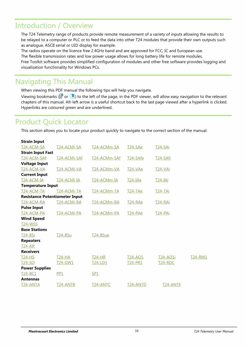
Mantracourt Electronics Limited T24 Telemetry User Manual 16
Introduction / Overview The T24 Telemetry range of products provide remote measurement of a variety of inputs allowing the results to
be relayed to a computer or PLC or to feed the data into other T24 modules that provide their own outputs such
as analogue, ASCII serial or LED display for example.
The radios operate on the licence free 2.4GHz band and are approved for FCC, IC and European use.
The flexible transmission rates and low power usage allows for long battery life for remote modules.
Free Toolkit software provides simplified configuration of modules and other free software provides logging and
visualisation functionality for Windows PCs.
Navigating This Manual When viewing this PDF manual the following tips will help you navigate.
Viewing bookmarks ( or ) to the left of the page, in the PDF viewer, will allow easy navigation to the relevant
chapters of this manual. Alt-left arrow is a useful shortcut back to the last page viewed after a hyperlink is clicked.
Hyperlinks are coloured green and are underlined.
Product Quick Locator This section allows you to locate your product quickly to navigate to the correct section of the manual.
Strain Input
T24-ACM-SA T24-ACMi-SA T24-ACMm-SA T24-SAe T24-SAi
Strain Input Fast
T24-ACM-SAf T24-ACMi-SAf T24-ACMm-SAf T24-SAfe T24-SAfi
Voltage Input
T24-ACM-VA T24-ACMi-VA T24-ACMm-VA T24-VAe T24-VAi
Current Input
T24-ACM-IA T24-ACMi-IA T24-ACMm-IA T24-IAe T24-IAi
Temperature Input
T24-ACM-TA T24-ACMi-TA T24-ACMm-TA T24-TAe T24-TAi
Resistance Potentiometer Input
T24-ACM-RA T24-ACMi-RA T24-ACMm-RA T24-RAe T24-RAi
Pulse Input
T24-ACM-PA T24-ACMi-PA T24-ACMm-PA T24-PAe T24-PAi
Wind Speed
T24-WSS
Base Stations
T24-BSi T24-BSu T24-BSue
Repeaters
T24-AR
Receivers
T24-HS T24-HA T24-HR T24-AO1 T24-AO1i T24-RM1
T24-SO T24-GW1 T24-LD1 T24-PR1 T24-RDC
Power Supplies
T24-BC1 PP1 SP1
Antennas
T24-ANTA T24-ANTB T24-ANTC T24-ANTD T24-ANTE
Mantracourt Electronics Limited T24 Telemetry User Manual 17
T24 Telemetry Basic Principles There are some basic radio settings and concepts that should be understood to effectively configure, deploy,
optimise and troubleshoot T24 telemetry systems.
Transmitters & Receivers Although all of the T24 modules are in fact transceivers and transmit as well as receive, they tend to mainly
operate as either a transmitter or receiver so we will choose to describe them as Transmitters and Receivers.
The T24 system was designed so that Transmitters are configured to send out messages at a user defined rate.
Receivers can then use this data to analyse, display or perform other actions depending on their function.
A PC and base station are only required to configure the modules although they may be part of a data collection
system. Once configured the T24 modules operate autonomously and only minimal control over the Transmitter
modules is usually required, by Receiver modules, such as sleeping or waking.
Transmitters
These are the sensor modules that measure strain, voltage, temperature etc. and send messages containing the
sensor value and status information at regular intervals for use by Receiver modules or for delivering to a PC via a
base station.
Because these modules need to be very power efficient to operate on batteries they operate in three distinct
modes. See Transmitter Module Modes of Operation later.
Receivers
These modules use messages provided by Transmitters and have functionality such as handheld displays, large
displays, analogue outputs and relay modules. These modules may also offer control over Transmitter modules
such as sleeping or waking.
Radio Channel and Group Key To be able to communicate, two radio modules must share some basic settings. There are ways to learn these and
to recover unknown settings and these are discussed later in the pairing section.
Radio Channel
This is the frequency that the radio operates on. T24 radio bandwidth is divided into 15 channels. Modules must
be on the same channel to be able to transfer messages.
Group Key
Group keys are a way of isolating groups of modules even if they are operating on the same radio channel. This
can improve efficiency and also offer security because no radio module can affect another or see their messages
unless they share the same group key.
A group key is defined by the user and is up to 15 alphanumeric characters.
Group keys were introduced in v3.0 radio firmware in March 2015. New radio modules will work with older radio
modules but group keys cannot be used.
Mantracourt Electronics Limited T24 Telemetry User Manual 18
Configuring Multiple Modules to Use the Same Radio Settings Please note that when you pair to a remote module the base station adopts the radio channel and group key of
the remote module.
To set the group key for a set of remote modules you can either:
Pair to each one in turn and set their radio channel and group key
or
Configure the base station by holding the shift key and clicking the Pair button on the Home page. Then
configure the base station to the required radio settings then use the tool on the radio settings advanced
page to pair to each module in the set to configure their radio settings to match the base station.
ID and Data Tags To configure a module its ID is used in communications. This is a unique 6 character identifier, such as FF1234,
which is allocated at the factory. This ID is hexadecimal so can consist of numbers 0-9 and letters A-F.
If a module is a Transmitter it sends messages without broadcasting its ID. It identifies messages by using a Data
Tag. This tag is a 4 character hexadecimal number and can be configured by the user. When modules leave the
factory this data tag is set to the last 4 characters of its ID.
When Receiver modules or software want to use messages sent by Transmitter modules they identify the
message they want by this Data Tag.
The reason Transmitter module messages are identified by a Data Tag rather than the unique ID is that this allows
replacement of a Transmitter module without having to reconfigure the many Receiver modules that may be
using its messages. It is only necessary to configure the replacement Transmitter module with the same data tag,
radio channel and group key and the rest of the system will not notice the difference.
Transmitter Module Modes of Operation
Normal
Normal mode involves taking a reading and sending a message then entering into a very low power state before
taking the next reading to maximise battery life.
Because it is not possible to communicate with the Transmitter module during this low power state a
‘configuration’ mode is required.
Configuration
Configuration mode forces the modules to pause in sending their messages and to disable their low power state
to enable configuration to take place. This is easily achieved by ‘Pairing’ when using the T24 Toolkit software.
Once configuration is complete the modules will resume their ‘normal’ mode operation.
Sleep
The last mode is sleep. Modules can be sent to sleep by other modules or they can go to sleep themselves when
their messages are no longer being used. See Sleep Delay Settings later.
When sleeping, the modules can be awakened on demand by other modules or software via the base station.
Mantracourt Electronics Limited T24 Telemetry User Manual 19
Transmitter Module Sleep Delay Settings Transmitter modules have a Sleep Delay setting (set in seconds) which allows the modules to go into Sleep mode
when their data messages are no longer required. This allows much longer battery life to be achieved.
Setting Sleep Delay to zero disables this function in the Transmitter modules and they will only go into Sleep
mode when told to do so.
Most Receiver modules and T24 software send Stay Awake messages when they see messages arrive from
Transmitter modules. In the Transmitter modules, if the Sleep Delay time period has elapsed without a Stay
Awake message arriving then the module will enter Sleep mode.
Usually the Stay Awake messages are sent every 5 seconds so Sleep Delays should be set to at least 10 seconds
but can be set to anything up to an hour for situations where the Receiver is likely to be out of range for periods
of time but where the Transmitter module is required to stay awake and in normal operational mode during that
time. It is usual that Sleep Delays are set somewhere between 30 and 300 seconds when required.
Pairing Because you need to know the radio settings configured in a module to be able to configure it, and there are no
visible clues to what those settings may be, there is a feature used by T24 modules that enable the radio settings
(i.e. the radio channel and the group key) to be determined and matched between two T24 modules.
Pairing is only required to determine and match radio settings and optionally to put T24 Transmitter modules in
configuration mode. Because in some installations the T24 modules can be buried deep inside other equipment
there had to be a way of indicating that a module has been selected to pair with without having physical access
to that module. Pairing was therefore designed to be activated by removing and re-applying the module’s power.
In some cases this is not practical so another possible solution is Soft Pairing see later.
Pairing From T24 Toolkit
When using the T24 Toolkit and a base station, pairing is used to connect to a module without having to know
anything about it beforehand. To pair, remove power from the required module, click a ‘Pair’ button in the
software and re-apply power to the module. The base station and module negotiate settings and the base
station is automatically configured to match the radio settings from the module and places the module into
configuration mode. Now the module can be configured and when complete it will return to normal operational
mode.
Pairing From a Receiver Module
Some Receiver modules allow pairing to a Transmitter module without requiring the Broadweigh Toolkit. For
example some handheld readers offer this feature by turning them on while holding a certain key after which the
power is applied to the Transmitter module. The radio settings are then negotiated and the Transmitter module
is automatically configured to match the handheld radio settings. The handheld learns the ID and data tags
required to be able to use messages from the Transmitter module. In this case no configuration mode is required
so the Transmitter module simply continues to operate in normal mode but with altered radio settings.
Mantracourt Electronics Limited T24 Telemetry User Manual 20
Soft Pairing Pairing by power cycling is absolute and will work under all circumstances. However, sometimes access to the
power supply of a module that you want to pair to can be restricted, a module 20 meters up a tower for example,
so the T24 Toolkit offers a way to soft pair.
To achieve this you need to know the radio channel and group key of the remote module and configure
the base station to match this. You must also know the unique ID of the module and armed with this you
can soft pair to the module. This works quite well with Receiver modules as they are not operating in low power
modes but the software does need to try and change Transmitter modules from their normal operation mode
into configuration mode.
This may not always work reliably in high traffic or high noise environments because there are a lot of messages
that need to be sent between the base station and the remote module which can be upset by the presence of too
many other messages on the same radio channel. If a connection cannot be made then power cycle pairing may
be the only option.
Configuring an Attached Base Station Because a base station is attached to your computer when you are using the T24 Toolkit you do not pair to it the
same way as with other T24 modules. To configure the base station using the Toolkit hold the shift key and click
the Pair button on the Home page.
Asynchronous Operation and Logging Transmitters send their messages at a fixed user defined interval regardless of whether anything is listening. This
message interval is timed from when the Transmitter has been woken or powered on so there is no
synchronisation of when the actual measurement is taken between different transmitters.
If you are logging information from multiple Transmitters using multiple channel logging software you should be
aware of how the software will store and record values.
The software stores the message values as they arrive from each Transmitter and when a log is to be recorded it is
the last value received by each Transmitter that is used.
This means that the values that are recorded could have been measured at any point during the Transmitter
message interval.
For example, if there are 10 Transmitters operating at 333ms message interval then when the values are recorded
to the log file you can only be sure that those values had been recorded within 333ms of each other.
So if there is a requirement that recorded sets of readings are within a certain time of each other, then that time is
the maximum message interval that should be set for the Transmitters regardless of the actual log interval of the
software (Which should always be greater than the Transmitter message interval).
Mantracourt Electronics Limited T24 Telemetry User Manual 21
Bandwidth Each radio channel (1-15) has a finite ability to carry information. When modules do not need to communicate
with each other they can be configured on separate radio channels and do not affect each other.
However, when multiple modules are on the same radio channel, even if they use different group keys, they are
all contributing to filling the available bandwidth.
Each message transmitted takes up around 3 milliseconds so if everything worked perfectly and all modules
transmitted at just the right time and with no gaps between then there could only ever be 300 messages per
second being transmitted on any one radio channel.
In reality there are factors that reduce this capacity.
Each module uses a technique to detect whether anyone else is transmitting before it transmits itself and this
takes a finite time. There can also be interference from other sources that can delay module transmissions.
Because of the transmission rate flexibility of the T24 modules there could be a few modules transmitting
messages at fast rates or many modules transmitting messages at slow rates or any combination of these.
Practically there is a limit of around 200 messages per second available per radio channel.
It should be noted that as the number of Transmitter modules increases there is more chance of message
collisions and so more messages are lost (remember that the Transmitter modules are sending their messages
out at regular intervals) thus reducing the average number of messages per second arriving per module.
So, for example, 2 modules may transmit at 100 times per second or 100 modules at a rate of 1 per second.
Repeaters and Repeater Subgroups Repeaters are able to retransmit messages so that the repeated signal is stronger than the original and so can
increase the range of systems or can bypass obstacles.
The repeater must be configured to operate on the same radio channel and use the same group keys as those
modules it is repeating.
Because the radio traffic is effectively doubled by a repeater there is a mechanism to reduce unnecessary
repetition of messages.
Sometimes a repeater will still see messages from modules that do not need to be repeated (Thus filling up
available bandwidth) so both repeaters and all other T24 modules have a setting called the repeater subgroup.
By default all subgroup settings are set to zero. A repeater will repeat a message from all modules whose
subgroup is either zero or matches its own subgroup. If a repeater subgroup is zero it will repeat messages from
all modules.
This is a simple way to break down modules into smaller groups and control what messages get repeated.
Changing the repeater subgroup is not normally necessary unless the bandwidth is very full due to either many
Transmitter modules being present or very fast transmissions from modules.
Mantracourt Electronics Limited T24 Telemetry User Manual 22
T24 Toolkit To configure the modules you must use the T24 Toolkit software application. This can be downloaded from our
web site or may be shipped with your products.
The software is suitable for all versions of Windows.
Run setup.exe and follow the prompts to install the software.
In the Toolkit all items that can be changed or interacted with by the user are coloured green.
To change a value just click on the relevant green item. You will then be presented with a new dialog window
allowing you to change the value.
This may use a slider, text box or list to allow your new value to be entered.
A base station will also be required to configure the T24 modules. If you have a USB version of the base station
(T24-BSu or T24-BSue) then you just need to plug this into a USB socket on your PC. If you are using an
alternative base station then please refer to the appropriate section of this manual.
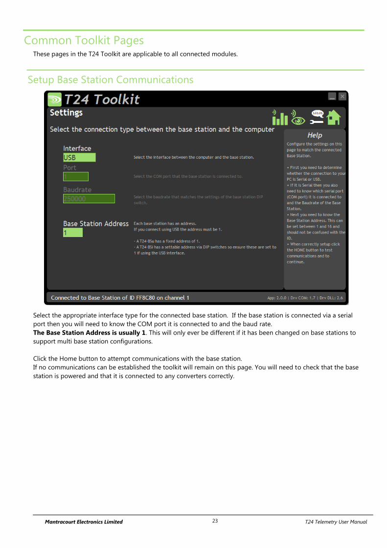
Mantracourt Electronics Limited T24 Telemetry User Manual 23
Common Toolkit Pages These pages in the T24 Toolkit are applicable to all connected modules.
Setup Base Station Communications
Select the appropriate interface type for the connected base station. If the base station is connected via a serial
port then you will need to know the COM port it is connected to and the baud rate.
The Base Station Address is usually 1. This will only ever be different if it has been changed on base stations to
support multi base station configurations.
Click the Home button to attempt communications with the base station.
If no communications can be established the toolkit will remain on this page. You will need to check that the base
station is powered and that it is connected to any converters correctly.
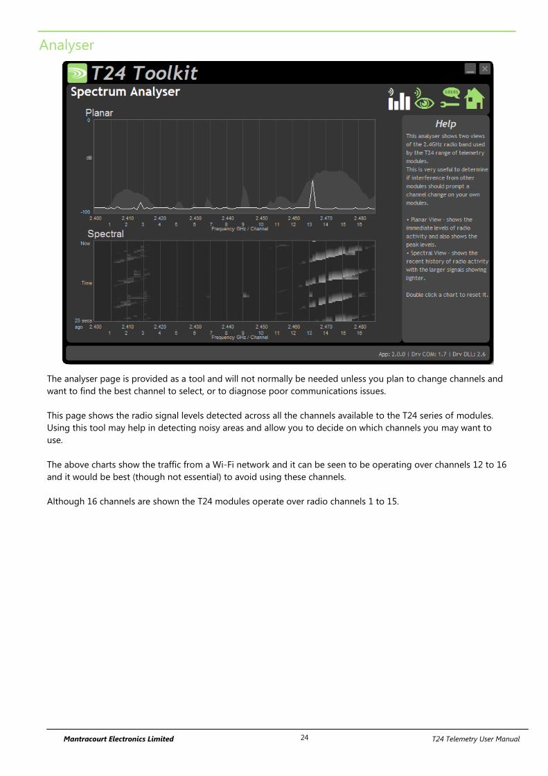
Mantracourt Electronics Limited T24 Telemetry User Manual 24
Analyser
The analyser page is provided as a tool and will not normally be needed unless you plan to change channels and
want to find the best channel to select, or to diagnose poor communications issues.
This page shows the radio signal levels detected across all the channels available to the T24 series of modules.
Using this tool may help in detecting noisy areas and allow you to decide on which channels you may want to
use.
The above charts show the traffic from a Wi-Fi network and it can be seen to be operating over channels 12 to 16
and it would be best (though not essential) to avoid using these channels.
Although 16 channels are shown the T24 modules operate over radio channels 1 to 15.
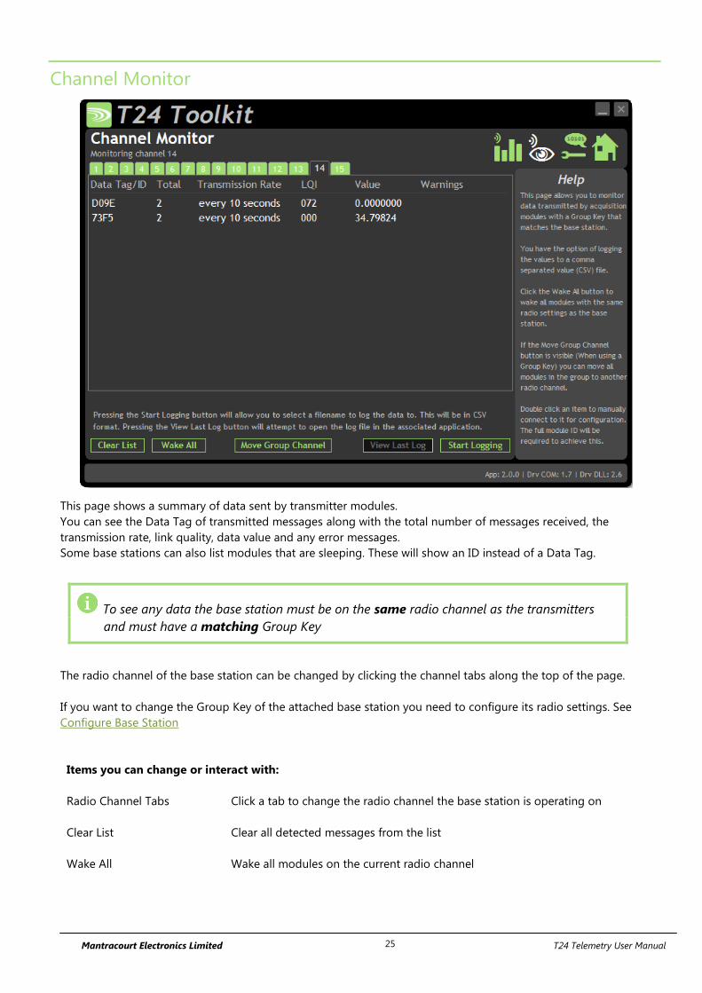
Mantracourt Electronics Limited T24 Telemetry User Manual 25
Channel Monitor
This page shows a summary of data sent by transmitter modules.
You can see the Data Tag of transmitted messages along with the total number of messages received, the
transmission rate, link quality, data value and any error messages.
Some base stations can also list modules that are sleeping. These will show an ID instead of a Data Tag.
To see any data the base station must be on the same radio channel as the transmitters
and must have a matching Group Key
The radio channel of the base station can be changed by clicking the channel tabs along the top of the page.
If you want to change the Group Key of the attached base station you need to configure its radio settings. See
Configure Base Station
Items you can change or interact with:
Radio Channel Tabs Click a tab to change the radio channel the base station is operating on
Clear List Clear all detected messages from the list
Wake All Wake all modules on the current radio channel
Mantracourt Electronics Limited T24 Telemetry User Manual 26
Start Logging Asks for a filename then logs the received data to a CSV file in the following
format:
Data Tag, Elasped ms, Value
View Last Log Will launch the application associated with CSV files and open the last logged
file.
Move Group Channel If the base station has a group key set then this button will be visible. Once at
least one module is present in the list this button will become enabled. Clicking
it will ask the user for a new radio channel then all detected transmitters, along
with all other modules on the same channel and group key such as handhelds,
will all be moved to the selected channel. Once this has been achieved the base
station itself will move and the list will start to fill again with messages on the
new radio channel.
You will only see a list of detected transmitters on this page
so you will need to ensure that any other receiver modules in
the group are available to be woken.
When this button is clicked all modules on the same radio
channel and group key will be woken before they are
changed to the target radio channel.
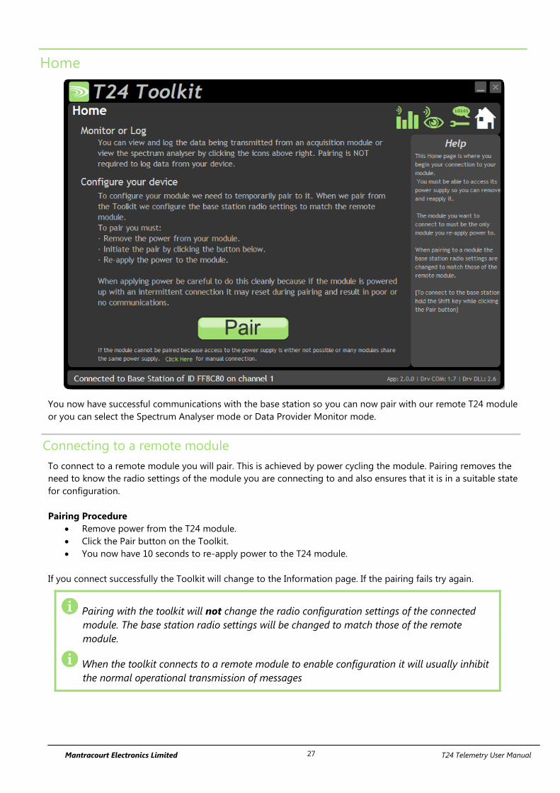
Mantracourt Electronics Limited T24 Telemetry User Manual 27
Home
You now have successful communications with the base station so you can now pair with our remote T24 module
or you can select the Spectrum Analyser mode or Data Provider Monitor mode.
Connecting to a remote module
To connect to a remote module you will pair. This is achieved by power cycling the module. Pairing removes the
need to know the radio settings of the module you are connecting to and also ensures that it is in a suitable state
for configuration.
Pairing Procedure
Remove power from the T24 module.
Click the Pair button on the Toolkit.
You now have 10 seconds to re-apply power to the T24 module.
If you connect successfully the Toolkit will change to the Information page. If the pairing fails try again.
Pairing with the toolkit will not change the radio configuration settings of the connected
module. The base station radio settings will be changed to match those of the remote
module.
When the toolkit connects to a remote module to enable configuration it will usually inhibit
the normal operational transmission of messages
Mantracourt Electronics Limited T24 Telemetry User Manual 28
Connecting to the attached base station module
To connect to and configure the connected base station, hold the shift key and click the Pair button.
Manual Connection
If you cannot get to the power supply of the remote module you can attempt to connect manually using Soft
Pairing. Click the ‘Click Here’ link at the bottom of the page and follow the prompts.
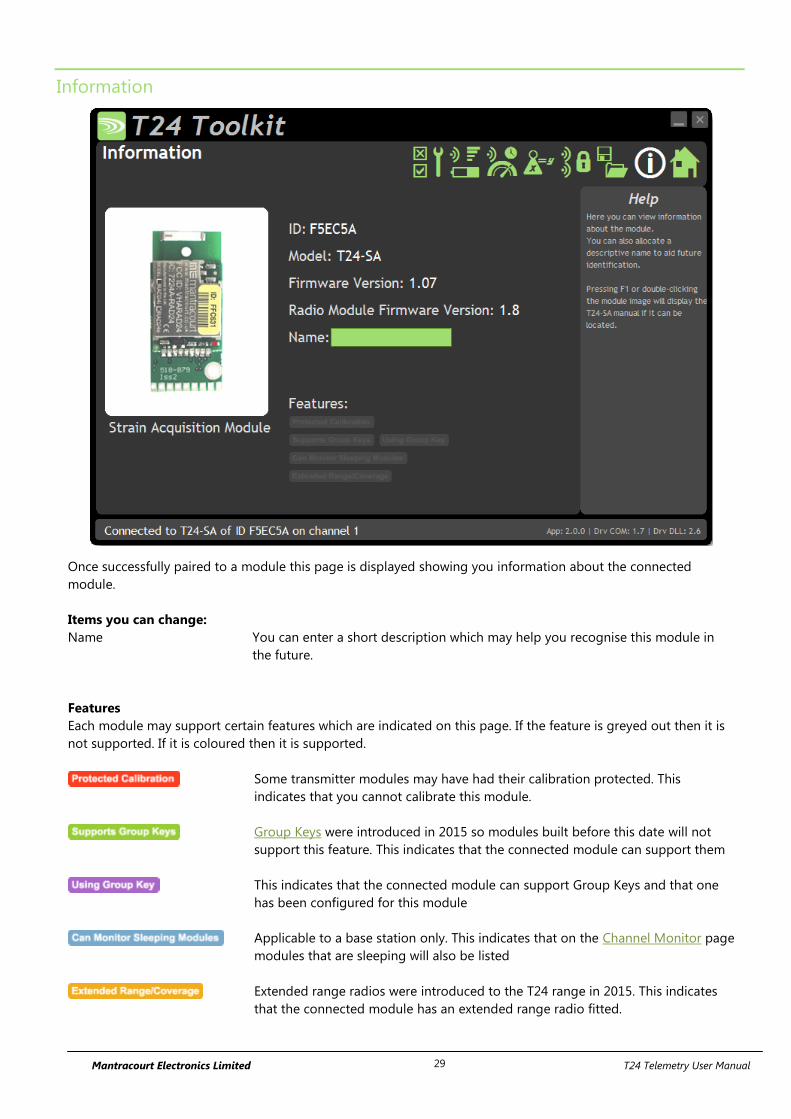
Mantracourt Electronics Limited T24 Telemetry User Manual 29
Information
Once successfully paired to a module this page is displayed showing you information about the connected
module.
Items you can change:
Name You can enter a short description which may help you recognise this module in
the future.
Features
Each module may support certain features which are indicated on this page. If the feature is greyed out then it is
not supported. If it is coloured then it is supported.
Some transmitter modules may have had their calibration protected. This
indicates that you cannot calibrate this module.
Group Keys were introduced in 2015 so modules built before this date will not
support this feature. This indicates that the connected module can support them
This indicates that the connected module can support Group Keys and that one
has been configured for this module
Applicable to a base station only. This indicates that on the Channel Monitor page
modules that are sleeping will also be listed
Extended range radios were introduced to the T24 range in 2015. This indicates
that the connected module has an extended range radio fitted.
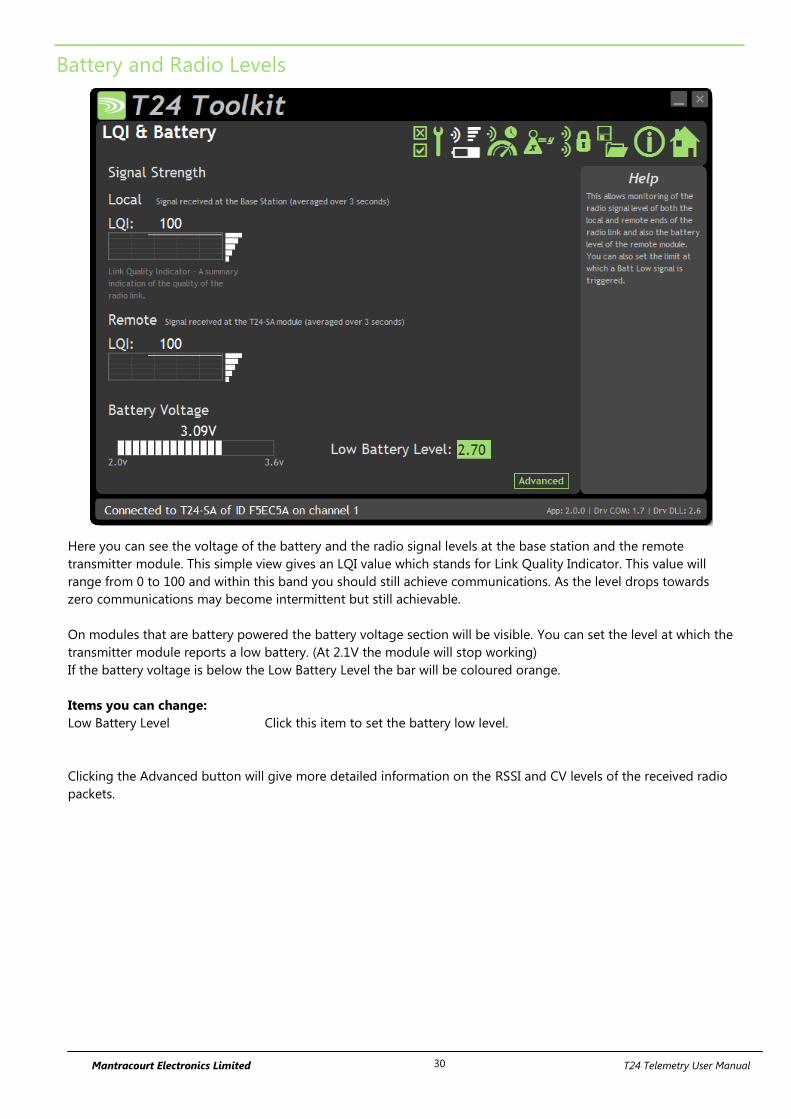
Mantracourt Electronics Limited T24 Telemetry User Manual 30
Battery and Radio Levels
Here you can see the voltage of the battery and the radio signal levels at the base station and the remote
transmitter module. This simple view gives an LQI value which stands for Link Quality Indicator. This value will
range from 0 to 100 and within this band you should still achieve communications. As the level drops towards
zero communications may become intermittent but still achievable.
On modules that are battery powered the battery voltage section will be visible. You can set the level at which the
transmitter module reports a low battery. (At 2.1V the module will stop working)
If the battery voltage is below the Low Battery Level the bar will be coloured orange.
Items you can change:
Low Battery Level Click this item to set the battery low level.
Clicking the Advanced button will give more detailed information on the RSSI and CV levels of the received radio
packets.
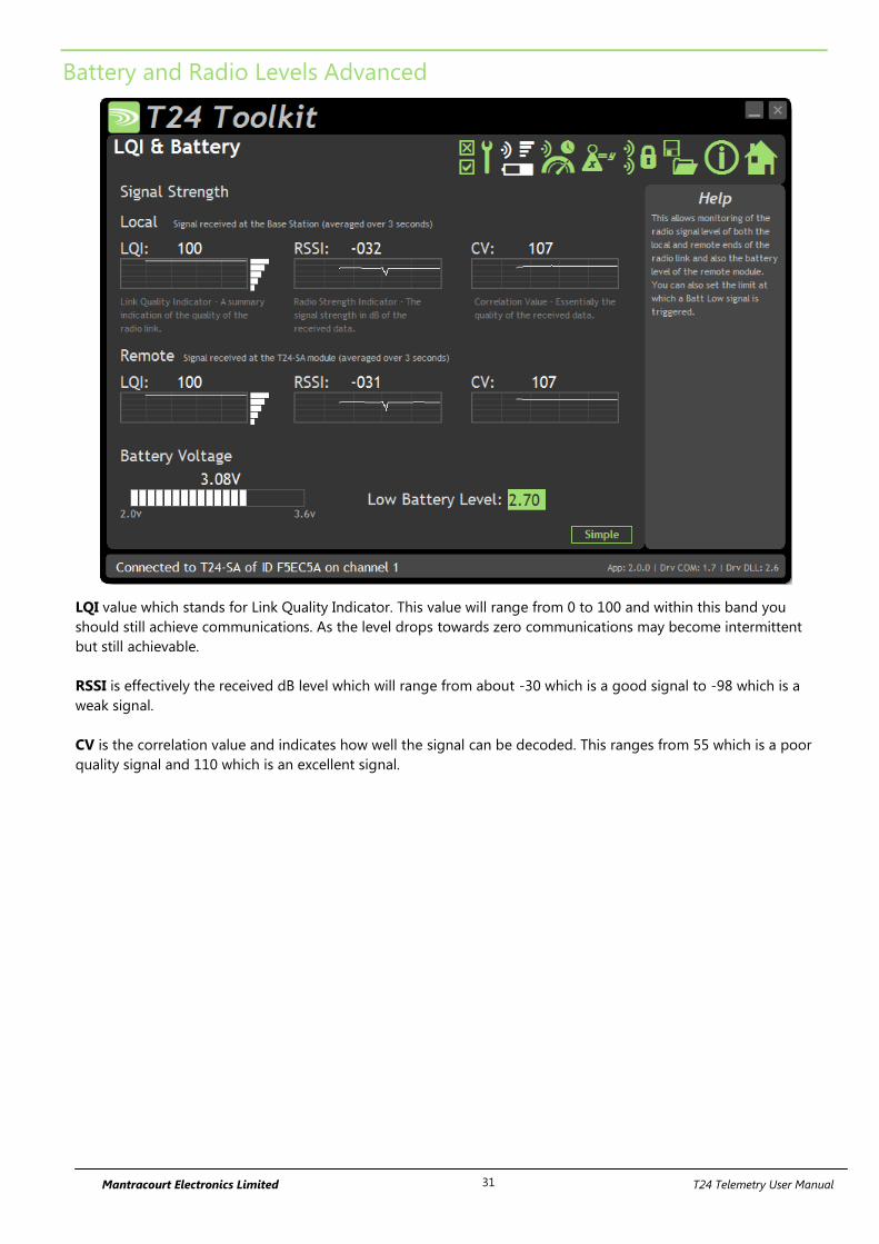
Mantracourt Electronics Limited T24 Telemetry User Manual 31
Battery and Radio Levels Advanced
LQI value which stands for Link Quality Indicator. This value will range from 0 to 100 and within this band you
should still achieve communications. As the level drops towards zero communications may become intermittent
but still achievable.
RSSI is effectively the received dB level which will range from about -30 which is a good signal to -98 which is a
weak signal.
CV is the correlation value and indicates how well the signal can be decoded. This ranges from 55 which is a poor
quality signal and 110 which is an excellent signal.
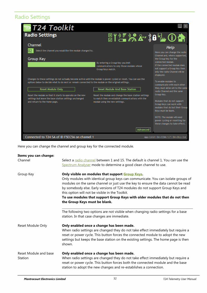
Mantracourt Electronics Limited T24 Telemetry User Manual 32
Radio Settings
Here you can change the channel and group key for the connected module.
Items you can change:
Channel Select a radio channel between 1 and 15. The default is channel 1. You can use the
Spectrum Analyser mode to determine a good clean channel to use.
Group Key Only visible on modules that support Group Keys.
Only modules with identical group keys can communicate. You can isolate groups of
modules on the same channel or just use the key to ensure the data cannot be read
by somebody else. Early versions of T24 modules do not support Group Keys and
this option will not be visible in the Toolkit.
To use modules that support Group Keys with older modules that do not then
the Group Keys must be blank.
The following two options are not visible when changing radio settings for a base
station. In that case changes are immediate.
Reset Module Only Only enabled once a change has been made.
When radio settings are changed they do not take effect immediately but require a
reset or power cycle. This button forces the connected module to adopt the new
settings but keeps the base station on the existing settings. The home page is then
shown.
Reset Module and base
Station
Only enabled once a change has been made.
When radio settings are changed they do not take effect immediately but require a
reset or power cycle. This button forces both the connected module and the base
station to adopt the new changes and re-establishes a connection.
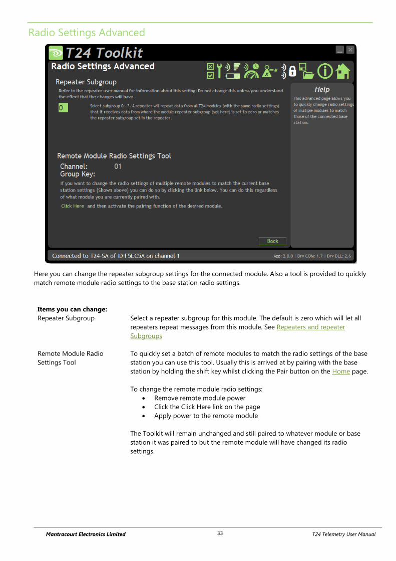
Mantracourt Electronics Limited T24 Telemetry User Manual 33
Radio Settings Advanced
Here you can change the repeater subgroup settings for the connected module. Also a tool is provided to quickly
match remote module radio settings to the base station radio settings.
Items you can change:
Repeater Subgroup Select a repeater subgroup for this module. The default is zero which will let all
repeaters repeat messages from this module. See Repeaters and repeater
Subgroups
Remote Module Radio
Settings Tool
To quickly set a batch of remote modules to match the radio settings of the base
station you can use this tool. Usually this is arrived at by pairing with the base
station by holding the shift key whilst clicking the Pair button on the Home page.
To change the remote module radio settings:
Remove remote module power
Click the Click Here link on the page
Apply power to the remote module
The Toolkit will remain unchanged and still paired to whatever module or base
station it was paired to but the remote module will have changed its radio
settings.
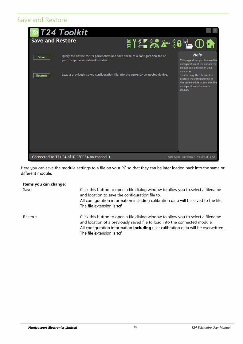
Mantracourt Electronics Limited T24 Telemetry User Manual 34
Save and Restore
Here you can save the module settings to a file on your PC so that they can be later loaded back into the same or
different module.
Items you can change:
Save Click this button to open a file dialog window to allow you to select a filename
and location to save the configuration file to.
All configuration information including calibration data will be saved to the file.
The file extension is tcf.
Restore Click this button to open a file dialog window to allow you to select a filename
and location of a previously saved file to load into the connected module.
All configuration information including user calibration data will be overwritten.
The file extension is tcf.
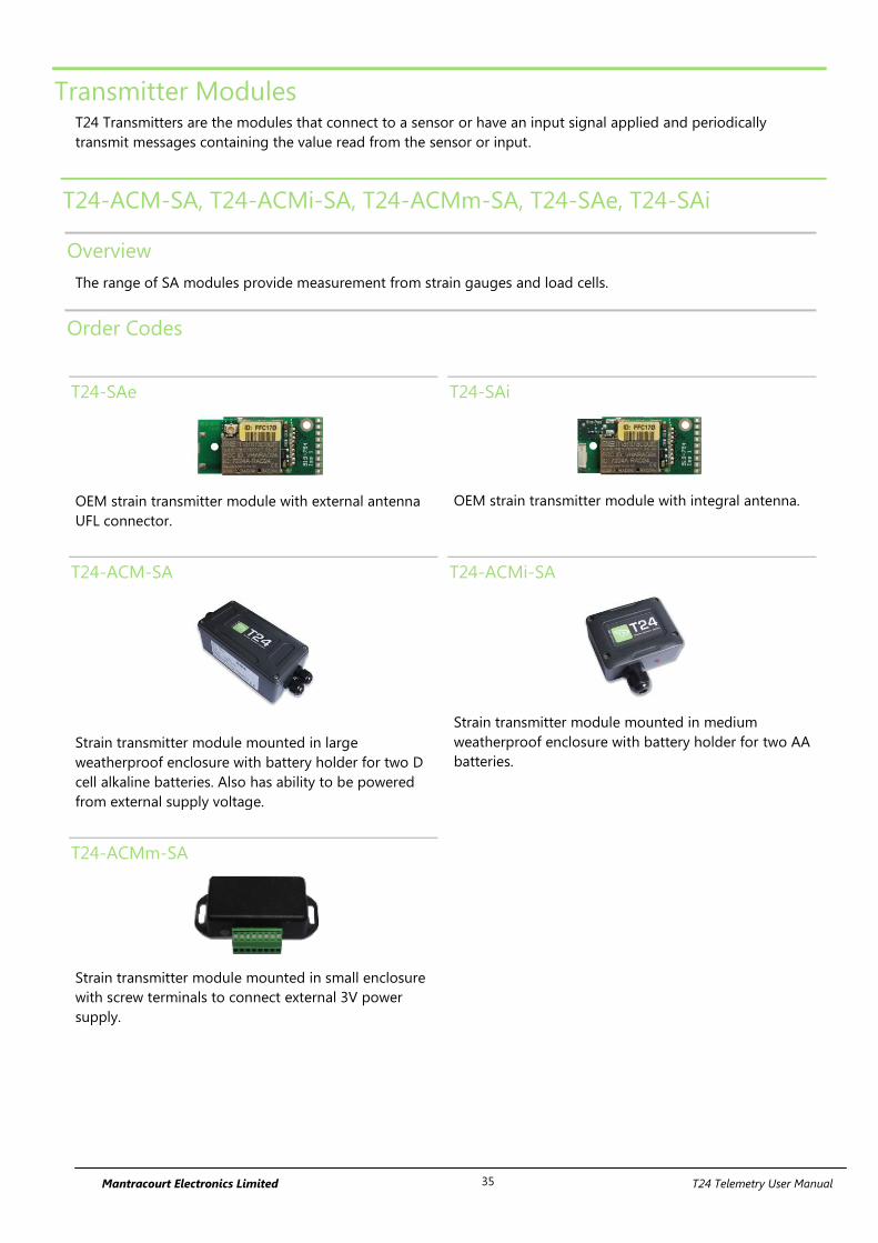
Mantracourt Electronics Limited T24 Telemetry User Manual 35
Transmitter Modules T24 Transmitters are the modules that connect to a sensor or have an input signal applied and periodically
transmit messages containing the value read from the sensor or input.
T24-ACM-SA, T24-ACMi-SA, T24-ACMm-SA, T24-SAe, T24-SAi
Overview
The range of SA modules provide measurement from strain gauges and load cells.
Order Codes
T24-SAe
OEM strain transmitter module with external antenna
UFL connector.
T24-SAi
OEM strain transmitter module with integral antenna.
T24-ACM-SA
Strain transmitter module mounted in large
weatherproof enclosure with battery holder for two D
cell alkaline batteries. Also has ability to be powered
from external supply voltage.
T24-ACMi-SA
Strain transmitter module mounted in medium
weatherproof enclosure with battery holder for two AA
batteries.
T24-ACMm-SA
Strain transmitter module mounted in small enclosure
with screw terminals to connect external 3V power
supply.
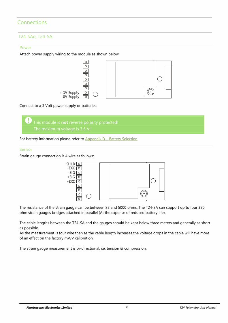
Mantracourt Electronics Limited T24 Telemetry User Manual 36
Connections
T24-SAe, T24-SAi
Power
Attach power supply wiring to the module as shown below:
+ 3V Supply0V Supply
Connect to a 3 Volt power supply or batteries.
This module is not reverse polarity protected!
The maximum voltage is 3.6 V!
For battery information please refer to Appendix D – Battery Selection
Sensor
Strain gauge connection is 4 wire as follows:
+EXC
SHLD-EXC
-SIG+SIG
The resistance of the strain gauge can be between 85 and 5000 ohms. The T24-SA can support up to four 350
ohm strain gauges bridges attached in parallel (At the expense of reduced battery life).
The cable lengths between the T24-SA and the gauges should be kept below three meters and generally as short
as possible.
As the measurement is four wire then as the cable length increases the voltage drops in the cable will have more
of an effect on the factory mV/V calibration.
The strain gauge measurement is bi-directional, i.e. tension & compression.

Mantracourt Electronics Limited T24 Telemetry User Manual 37
T24-ACM-SA
Power
Power can be supplied by fitting two ‘D’ cell alkaline 1.5 V batteries or the module can be supplied from an
external 5 Vdc to 18 Vdc source.
In both cases you need to fit the JP1 power jumper to supply power to the transmitter module.
When powered from the external DC source the LED will illuminate.
2 X D Cell Batteries
AB
0V+Supply
12345
Power Jumper JP1
LED
For battery information please refer to Appendix D – Battery Selection
Sensor
The strain gauge input is connected to the module via a 2 part screw terminal block.
Screw Terminal Function
1 +5 V Excitation
2 +Signal
3 -Signal
4 -Excitation
5 Shield
A
B
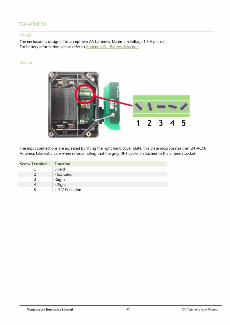
Mantracourt Electronics Limited T24 Telemetry User Manual 38
T24-ACMi-SA
Power
The enclosure is designed to accept two AA batteries. Maximum voltage 1.8 V per cell.
For battery information please refer to Appendix D – Battery Selection
Sensor
The input connections are accessed by lifting the right hand cover plate, this plate incorporates the T24-ACMi
Antenna; take extra care when re-assembling that the grey UHF cable is attached to the antenna socket.
Screw Terminal Function
1 Shield
2 - Excitation
3 -Signal
4 +Signal
5 + 5 V Excitation
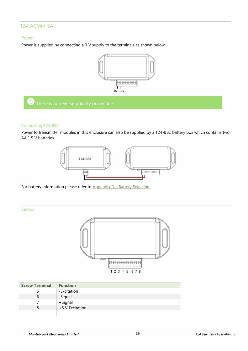
Mantracourt Electronics Limited T24 Telemetry User Manual 39
T24-ACMm-SA
Power
Power is supplied by connecting a 3 V supply to the terminals as shown below.
There is no reverse polarity protection
Connecting T24-BB1
Power to transmitter modules in this enclosure can also be supplied by a T24-BB1 battery box which contains two
AA 1.5 V batteries.
For battery information please refer to Appendix D – Battery Selection
Sensor
Screw Terminal Function
5 -Excitation
6 -Signal
7 +Signal
8 +5 V Excitation
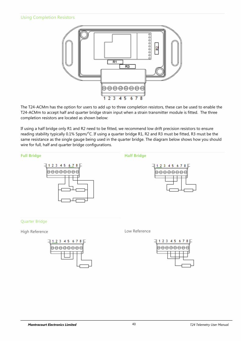
Mantracourt Electronics Limited T24 Telemetry User Manual 40
Using Completion Resistors
The T24-ACMm has the option for users to add up to three completion resistors, these can be used to enable the
T24-ACMm to accept half and quarter bridge strain input when a strain transmitter module is fitted. The three
completion resistors are located as shown below:
If using a half bridge only R1 and R2 need to be fitted, we recommend low drift precision resistors to ensure
reading stability typically 0.1% 5ppm/oC. If using a quarter bridge R1, R2 and R3 must be fitted, R3 must be the
same resistance as the single gauge being used in the quarter bridge. The diagram below shows how you should
wire for full, half and quarter bridge configurations.
Full Bridge
Half Bridge
Quarter Bridge
High Reference
Low Reference
Mantracourt Electronics Limited T24 Telemetry User Manual 41
Shield Connections (All Enclosures)
We recommend the following rules to determine whether there should be a connection between the transmitter
module shield and the sensor chassis or cable:
1. If the sensor is remote to the transmitter module and the screen of the signal cable is NOT connected to the
sensor chassis then the cable screen should be connected to the transmitter module shield connection.
2. If the sensor is remote to the transmitter module and the screen of the signal cable IS connected to the sensor
chassis then the cable screen should be NOT connected to the transmitter module shield connection.
3. If the transmitter module is integral to the sensor or mounted very close and the module is mounted on a metal
chassis then the answer to whether the transmitter module shield connection should be connected to the metal
chassis is a matter of experimentation. This connection must be as short as possible. The T24 Toolkit can be used
to chart the signal levels and tests should be undertaken to determine whether there is a better radio signal with
or without the shield/chassis connection. The quality of the measured reading should also be looked at. In cases
where the shield/chassis connection makes no difference to the radio signal or the reading quality then the
connection should be made.
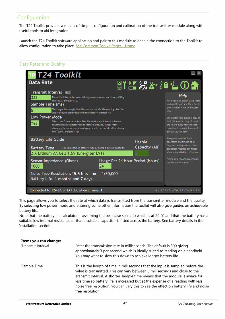
Mantracourt Electronics Limited T24 Telemetry User Manual 42
Configuration
The T24 Toolkit provides a means of simple configuration and calibration of the transmitter module along with
useful tools to aid integration.
Launch the T24 Toolkit software application and pair to this module to enable the connection to the Toolkit to
allow configuration to take place. See Common Toolkit Pages - Home
Data Rates and Quality
This page allows you to select the rate at which data is transmitted from the transmitter module and the quality.
By selecting low power mode and entering some other information the toolkit will also give guides on achievable
battery life.
Note that the battery life calculator is assuming the best case scenario which is at 20 °C and that the battery has a
suitable low internal resistance or that a suitable capacitor is fitted across the battery. See battery details in the
Installation section.
Items you can change:
Transmit Interval Enter the transmission rate in milliseconds. The default is 300 giving
approximately 3 per second which is ideally suited to reading on a handheld.
You may want to slow this down to achieve longer battery life.
Sample Time This is the length of time in milliseconds that the input is sampled before the
value is transmitted. This can vary between 5 milliseconds and close to the
Transmit Interval. A shorter sample time means that the module is awake for
less time so battery life is increased but at the expense of a reading with less
noise free resolution. You can vary this to see the effect on battery life and noise
free resolution.
Mantracourt Electronics Limited T24 Telemetry User Manual 43
Low Power Mode Unless the transmitter module is non battery powered this should be set to Yes.
In between transmissions the transmitter module will enter sleep mode which,
for some modules such as the strain gauge transmitter module, will have a
massive effect on battery life.
A reason for not using Low Power Mode would be if using the module in a
Master-Slave arrangement with PC for example.
Battery Type This is not a parameter of the module but information used by the battery life
guide. You can choose from some preset batteries or choose custom to allow
you to select your own battery capacity. See below. This will also offer to change
the Battery Low Level if the level suitable for the chosen battery is not the level
currently set.
Usable Capacity This is not a parameter of the module but information used by the battery life
guide. This is the capacity of the battery in Amp Hours and has a profound
effect on battery life calculations. This capacity needs to be calculated from
battery manufacturer’s data sheets to take into account that you can only use
batteries down to 2.1 volts so in the case of twin AA cells this would be 1.05
volts.
Generally the usable capacity will not be as high as that advertised by the
battery manufacturer. Temperature and internal resistance of the battery are not
taken into account in the guide.
Sensor Resistance This is only available for certain transmitter modules. This is not a parameter of
the module but information used by the battery life guide. Enter the resistance
of the connected strain gauge in Ohms.
Usage Per 24 Hour Period Enter the number of hours per 24 hour period that the T24-HS handheld will be
turned on and communicating with a transmitter module.
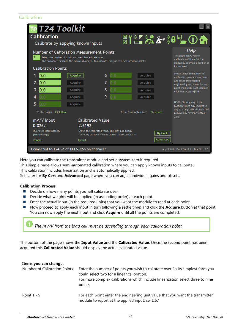
Mantracourt Electronics Limited T24 Telemetry User Manual 44
Calibration
Here you can calibrate the transmitter module and set a system zero if required.
This simple page allows semi-automated calibration where you can apply known inputs to calibrate.
This calibration includes linearization and is automatically applied.
See later for By Cert and Advanced page where you can adjust individual gains and offsets.
Calibration Process
Decide on how many points you will calibrate over.
Decide what weights will be applied (in ascending order) at each point.
Enter the actual input (in the required units) that you want the module to read at each point.
Now proceed to apply each input in turn (allowing a settle time) and click the Acquire button at that point.
You can now apply the next input and click Acquire until all the points are completed.
The mV/V from the load cell must be ascending through each calibration point.
The bottom of the page shows the Input Value and the Calibrated Value. Once the second point has been
acquired this Calibrated Value should display the actual calibrated value.
Items you can change:
Number of Calibration Points Enter the number of points you wish to calibrate over. In its simplest form you
could select two for a linear calibration.
For more complex calibrations which include linearization select three to nine
points.
Point 1 - 9 For each point enter the engineering unit value that you want the transmitter
module to report at the applied input. i.e. 1.67

Mantracourt Electronics Limited T24 Telemetry User Manual 45
Acquire 1 - 9 Click this button when the input has been applied and the reading has been
allowed to settle. This will acquire the reading and allow you to move to the
next points. You will be able to click the button again to re-acquire.
Start Again Click here to restart the calibration.
System Zero Once calibrated you may want to remove a fixed system value. In the case of a
strain gauge input this may be the weight of a sling, shackle, load bed etc.
Apply the required input and click here to set the system zero. The current input
will be removed from subsequent readings so that the reading will be zero.
To edit this value manually click the Advanced button.
System Zero is stored in non-volatile memory in the transmitter module.
By Cert. You can click the By Cert button to calibrate against a sensor calibration sheet.
You just need to enter the input values and associated engineering unit
required output value of at least 2 points.
This will take you to a different screen.
Advanced Clicking the advanced button will allow you to edit the gains and offsets for
each available calibration point. This will take you to a different screen.
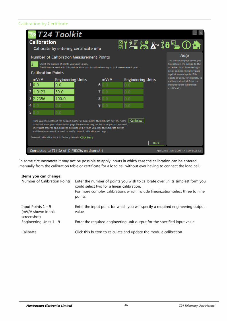
Mantracourt Electronics Limited T24 Telemetry User Manual 46
Calibration by Certificate
In some circumstances it may not be possible to apply inputs in which case the calibration can be entered
manually from the calibration table or certificate for a load cell without ever having to connect the load cell.
Items you can change:
Number of Calibration Points Enter the number of points you wish to calibrate over. In its simplest form you
could select two for a linear calibration.
For more complex calibrations which include linearization select three to nine
points.
Input Points 1 – 9
(mV/V shown in this
screenshot)
Enter the input point for which you will specify a required engineering output
value
Engineering Units 1 - 9 Enter the required engineering unit output for the specified input value
Calibrate Click this button to calculate and update the module calibration
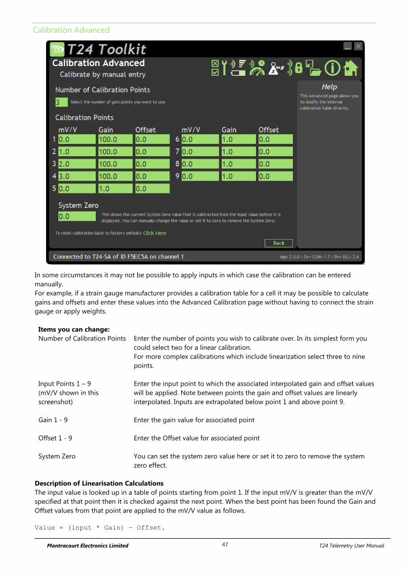
Mantracourt Electronics Limited T24 Telemetry User Manual 47
Calibration Advanced
In some circumstances it may not be possible to apply inputs in which case the calibration can be entered
manually.
For example, if a strain gauge manufacturer provides a calibration table for a cell it may be possible to calculate
gains and offsets and enter these values into the Advanced Calibration page without having to connect the strain
gauge or apply weights.
Items you can change:
Number of Calibration Points Enter the number of points you wish to calibrate over. In its simplest form you
could select two for a linear calibration.
For more complex calibrations which include linearization select three to nine
points.
Input Points 1 – 9
(mV/V shown in this
screenshot)
Enter the input point to which the associated interpolated gain and offset values
will be applied. Note between points the gain and offset values are linearly
interpolated. Inputs are extrapolated below point 1 and above point 9.
Gain 1 - 9 Enter the gain value for associated point
Offset 1 - 9 Enter the Offset value for associated point
System Zero You can set the system zero value here or set it to zero to remove the system
zero effect.
Description of Linearisation Calculations
The input value is looked up in a table of points starting from point 1. If the input mV/V is greater than the mV/V
specified at that point then it is checked against the next point. When the best point has been found the Gain and
Offset values from that point are applied to the mV/V value as follows.
Value = (input * Gain) – Offset.
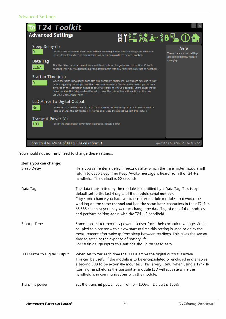
Mantracourt Electronics Limited T24 Telemetry User Manual 48
Advanced Settings
You should not normally need to change these settings.
Items you can change:
Sleep Delay Here you can enter a delay in seconds after which the transmitter module will
return to deep sleep if no Keep Awake message is heard from the T24-HS
handheld. The default is 60 seconds.
Data Tag The data transmitted by the module is identified by a Data Tag. This is by
default set to the last 4 digits of the module serial number.
If by some chance you had two transmitter module modules that would be
working on the same channel and had the same last 4 characters in their ID (1 in
65,535 chances) you may want to change the data Tag of one of the modules
and perform pairing again with the T24-HS handheld.
Startup Time Some transmitter modules power a sensor from their excitation voltage. When
coupled to a sensor with a slow startup time this setting is used to delay the
measurement after wakeup from sleep between readings. This gives the sensor
time to settle at the expense of battery life.
For strain gauge inputs this settings should be set to zero.
LED Mirror to Digital Output When set to Yes each time the LED is active the digital output is active.
This can be useful if the module is to be encapsulated or enclosed and enables
a second LED to be externally mounted. This is very useful when using a T24-HR
roaming handheld as the transmitter module LED will activate while the
handheld is in communications with the module.
Transmit power Set the transmit power level from 0 – 100%. Default is 100%
Mantracourt Electronics Limited T24 Telemetry User Manual 49
Enclosure & Mounting
This module is available in a number of different enclosure types. Locate your module and follow the link to view
dimensional and mounting information for that particular enclosure.
T24-SAe, T24-SAi
These OEM modules are bare PCB modules. Please see Appendix A – Enclosures & Mounting – OEM Transmitter
Modules for more information.
T24-ACM-SA
This module is fitted inside our large enclosure. Please see Appendix A – Enclosures & Mounting – ACM for more
information.
T24-ACMi-SA
This module is fitted inside our medium enclosure. Please see Appendix A – Enclosures & Mounting – ACMi for
more information.
T24-ACMm-SA
This module is fitted inside our small enclosure. Please see Appendix A – Enclosures & Mounting – ACMm for
more information.
Antennas
T24-SAi
This module uses an integrated chip antenna. See Appendix B – Antennas – Internal Chip Antenna
T24-SAe
Only the T24-SAe module allows for the fitting of external antennas. The choices are:
T24-ANTA PCB Antenna See Appendix B – Antennas – T24-ANTA
T24-ANTB Dipole Antenna See Appendix B – Antennas – T24-ANTB
T24-ANTC Dipole Antenna Swivel See Appendix B – Antennas – T24-ANTC
T24-ANTD Puck Antenna SMA See Appendix B – Antennas – T24-ANTD
T24-ANTE Puck Antenna UFL See Appendix B – Antennas – T24-ANTE
T24-ACM-SA, T24-ACMi-SA, T24-ACMm-SA
These modules have the antenna already fitted inside the enclosure so there are no specific mounting
requirements.
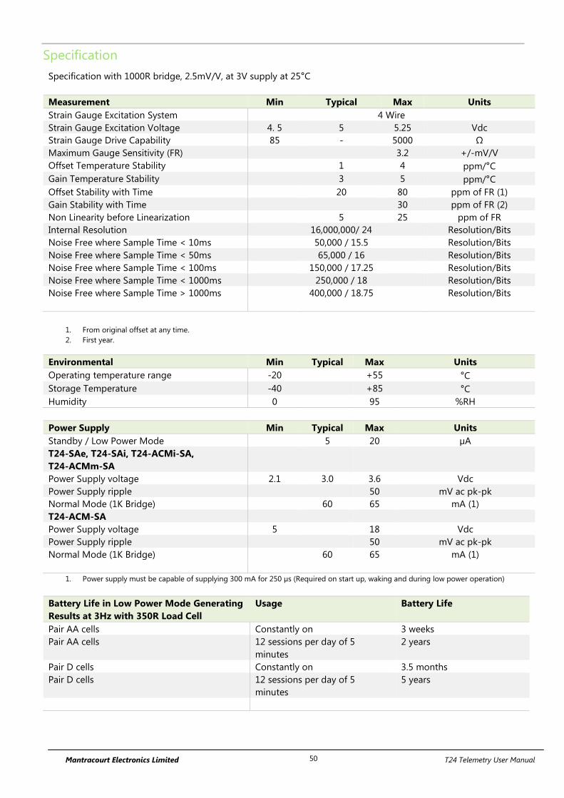
Mantracourt Electronics Limited T24 Telemetry User Manual 50
Specification
Specification with 1000R bridge, 2.5mV/V, at 3V supply at 25°C
Measurement Min Typical Max Units
Strain Gauge Excitation System 4 Wire
Strain Gauge Excitation Voltage 4. 5 5 5.25 Vdc
Strain Gauge Drive Capability 85 - 5000 Ω
Maximum Gauge Sensitivity (FR) 3.2 +/-mV/V
Offset Temperature Stability 1 4 ppm/°C
Gain Temperature Stability 3 5 ppm/°C
Offset Stability with Time 20 80 ppm of FR (1)
Gain Stability with Time 30 ppm of FR (2)
Non Linearity before Linearization 5 25 ppm of FR
Internal Resolution 16,000,000/ 24 Resolution/Bits
Noise Free where Sample Time < 10ms 50,000 / 15.5 Resolution/Bits
Noise Free where Sample Time < 50ms 65,000 / 16 Resolution/Bits
Noise Free where Sample Time < 100ms 150,000 / 17.25 Resolution/Bits
Noise Free where Sample Time < 1000ms 250,000 / 18 Resolution/Bits
Noise Free where Sample Time > 1000ms 400,000 / 18.75 Resolution/Bits
1. From original offset at any time.
2. First year.
Environmental Min Typical Max Units
Operating temperature range -20 +55 °C
Storage Temperature -40 +85 °C
Humidity 0 95 %RH
Power Supply Min Typical Max Units
Standby / Low Power Mode 5 20 µA
T24-SAe, T24-SAi, T24-ACMi-SA,
T24-ACMm-SA
Power Supply voltage 2.1 3.0 3.6 Vdc
Power Supply ripple 50 mV ac pk-pk
Normal Mode (1K Bridge) 60 65 mA (1)
T24-ACM-SA
Power Supply voltage 5 18 Vdc
Power Supply ripple 50 mV ac pk-pk
Normal Mode (1K Bridge) 60 65 mA (1)
1. Power supply must be capable of supplying 300 mA for 250 µs (Required on start up, waking and during low power operation)
Battery Life in Low Power Mode Generating
Results at 3Hz with 350R Load Cell
Usage Battery Life
Pair AA cells Constantly on 3 weeks
Pair AA cells 12 sessions per day of 5
minutes
2 years
Pair D cells Constantly on 3.5 months
Pair D cells 12 sessions per day of 5
minutes
5 years

Mantracourt Electronics Limited T24 Telemetry User Manual 51
Radio Range
To determine radio range please refer to Appendix B – Antenna Range
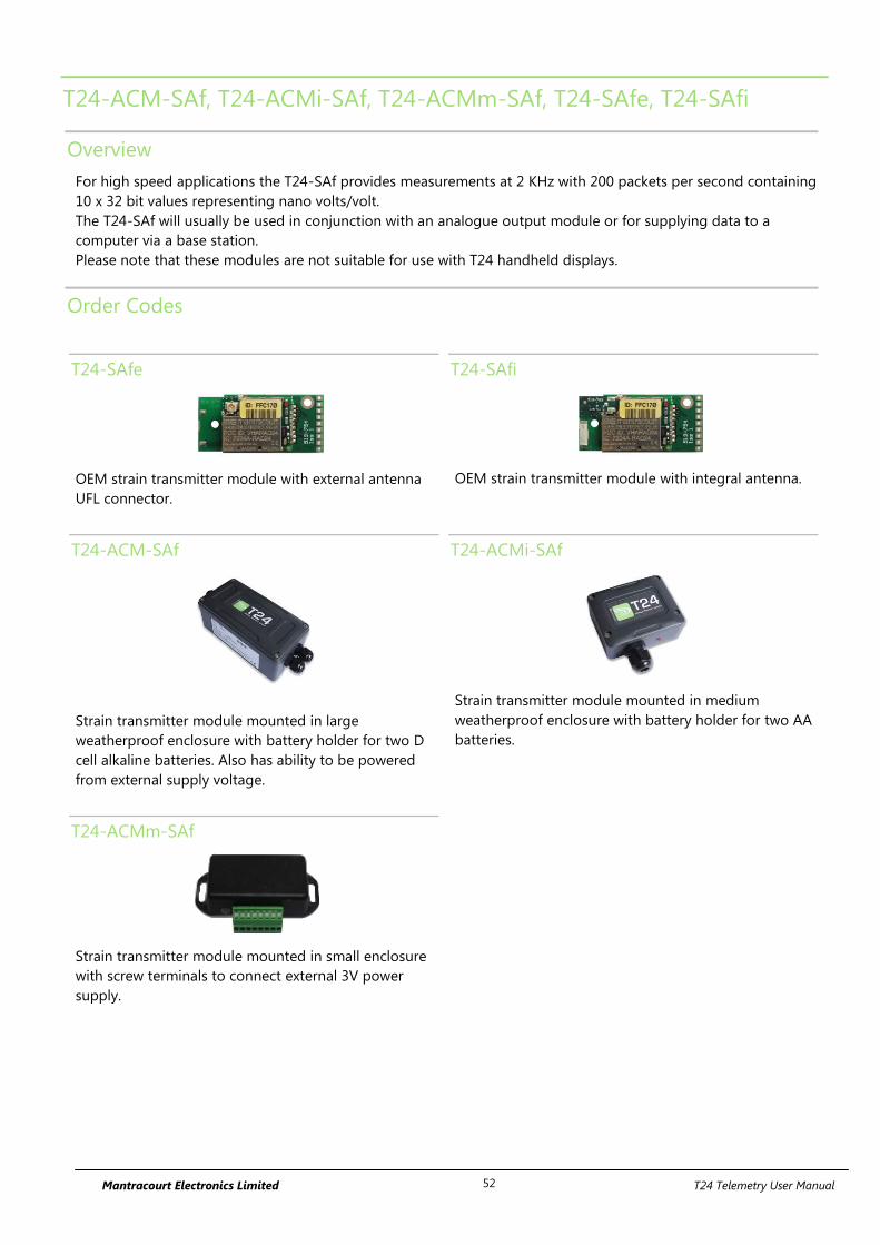
Mantracourt Electronics Limited T24 Telemetry User Manual 52
T24-ACM-SAf, T24-ACMi-SAf, T24-ACMm-SAf, T24-SAfe, T24-SAfi
Overview
For high speed applications the T24-SAf provides measurements at 2 KHz with 200 packets per second containing
10 x 32 bit values representing nano volts/volt.
The T24-SAf will usually be used in conjunction with an analogue output module or for supplying data to a
computer via a base station.
Please note that these modules are not suitable for use with T24 handheld displays.
Order Codes
T24-SAfe
OEM strain transmitter module with external antenna
UFL connector.
T24-SAfi
OEM strain transmitter module with integral antenna.
T24-ACM-SAf
Strain transmitter module mounted in large
weatherproof enclosure with battery holder for two D
cell alkaline batteries. Also has ability to be powered
from external supply voltage.
T24-ACMi-SAf
Strain transmitter module mounted in medium
weatherproof enclosure with battery holder for two AA
batteries.
T24-ACMm-SAf
Strain transmitter module mounted in small enclosure
with screw terminals to connect external 3V power
supply.
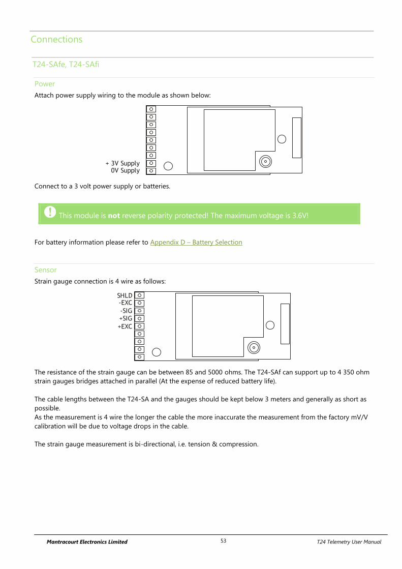
Mantracourt Electronics Limited T24 Telemetry User Manual 53
Connections
T24-SAfe, T24-SAfi
Power
Attach power supply wiring to the module as shown below:
+ 3V Supply0V Supply
Connect to a 3 volt power supply or batteries.
This module is not reverse polarity protected! The maximum voltage is 3.6V!
For battery information please refer to Appendix D – Battery Selection
Sensor
Strain gauge connection is 4 wire as follows:
+EXC
SHLD-EXC
-SIG+SIG
The resistance of the strain gauge can be between 85 and 5000 ohms. The T24-SAf can support up to 4 350 ohm
strain gauges bridges attached in parallel (At the expense of reduced battery life).
The cable lengths between the T24-SA and the gauges should be kept below 3 meters and generally as short as
possible.
As the measurement is 4 wire the longer the cable the more inaccurate the measurement from the factory mV/V
calibration will be due to voltage drops in the cable.
The strain gauge measurement is bi-directional, i.e. tension & compression.
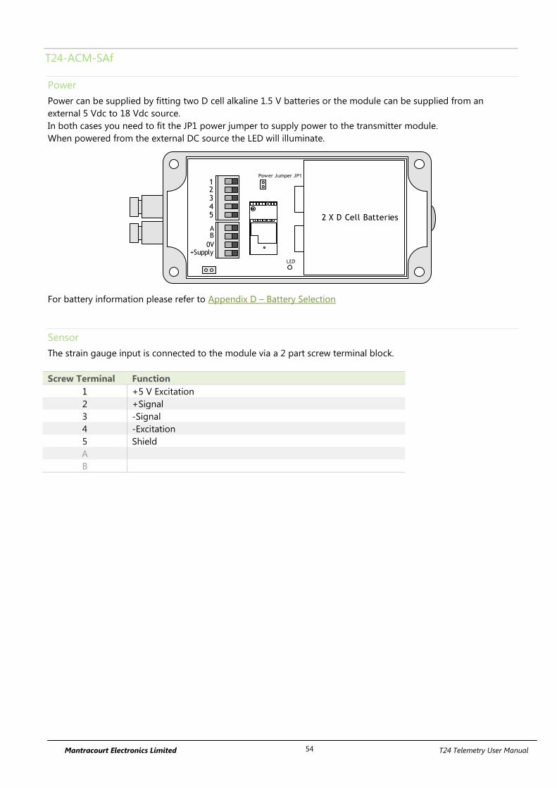
Mantracourt Electronics Limited T24 Telemetry User Manual 54
T24-ACM-SAf
Power
Power can be supplied by fitting two D cell alkaline 1.5 V batteries or the module can be supplied from an
external 5 Vdc to 18 Vdc source.
In both cases you need to fit the JP1 power jumper to supply power to the transmitter module.
When powered from the external DC source the LED will illuminate.
2 X D Cell Batteries
AB
0V+Supply
12345
Power Jumper JP1
LED
For battery information please refer to Appendix D – Battery Selection
Sensor
The strain gauge input is connected to the module via a 2 part screw terminal block.
Screw Terminal Function
1 +5 V Excitation
2 +Signal
3 -Signal
4 -Excitation
5 Shield
A
B
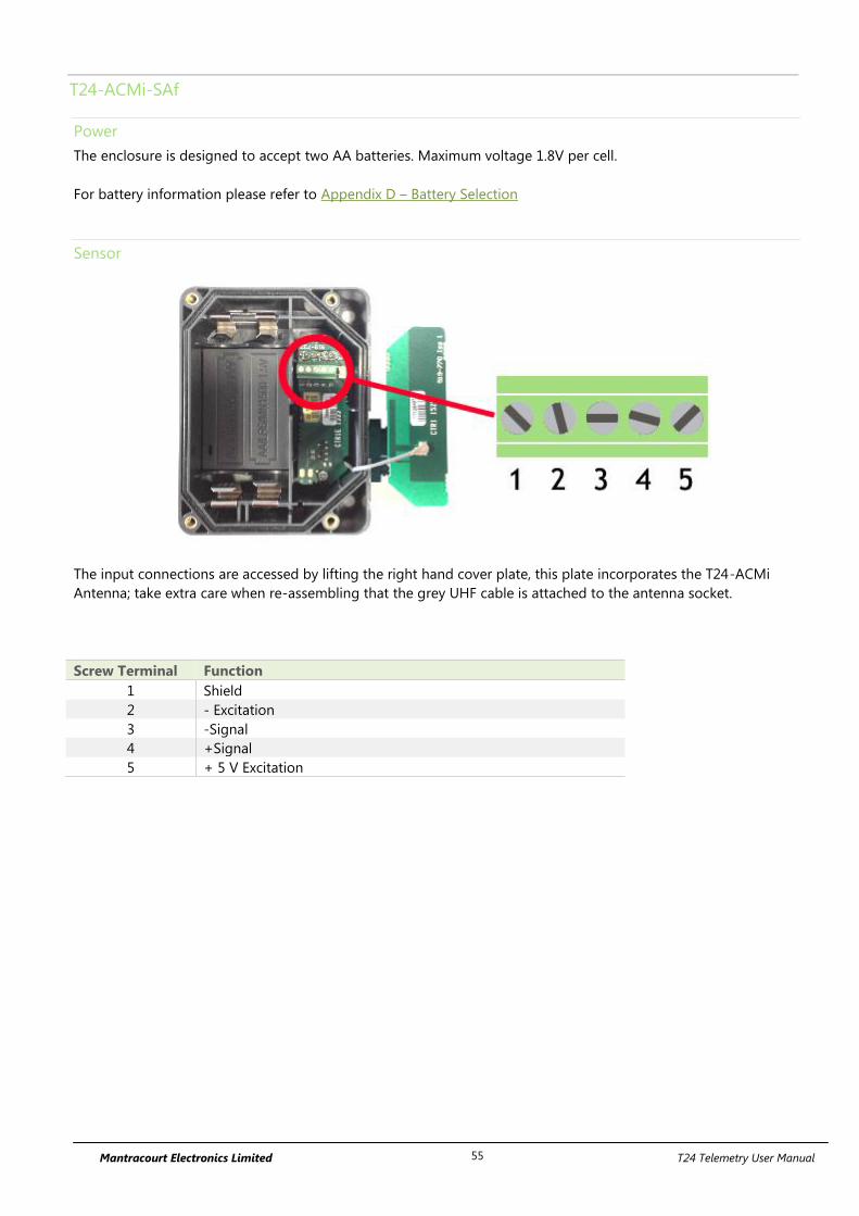
Mantracourt Electronics Limited T24 Telemetry User Manual 55
T24-ACMi-SAf
Power
The enclosure is designed to accept two AA batteries. Maximum voltage 1.8V per cell.
For battery information please refer to Appendix D – Battery Selection
Sensor
The input connections are accessed by lifting the right hand cover plate, this plate incorporates the T24-ACMi
Antenna; take extra care when re-assembling that the grey UHF cable is attached to the antenna socket.
Screw Terminal Function
1 Shield
2 - Excitation
3 -Signal
4 +Signal
5 + 5 V Excitation

Mantracourt Electronics Limited T24 Telemetry User Manual 56
T24-ACMm-SAf
Power
Power is supplied by connecting a 3V supply to the first two screw terminals as shown below.
There is no reverse polarity protection.
Connecting T24-BB1
Power to transmitter modules in this enclosure can also be supplied by a T24-BB1 battery box which contains two
AA 1.5 V batteries.
For battery information please refer to Appendix D – Battery Selection
Sensor
Screw Terminal Function
5 -Excitation
6 -Signal
7 +Signal
8 +5 V Excitation
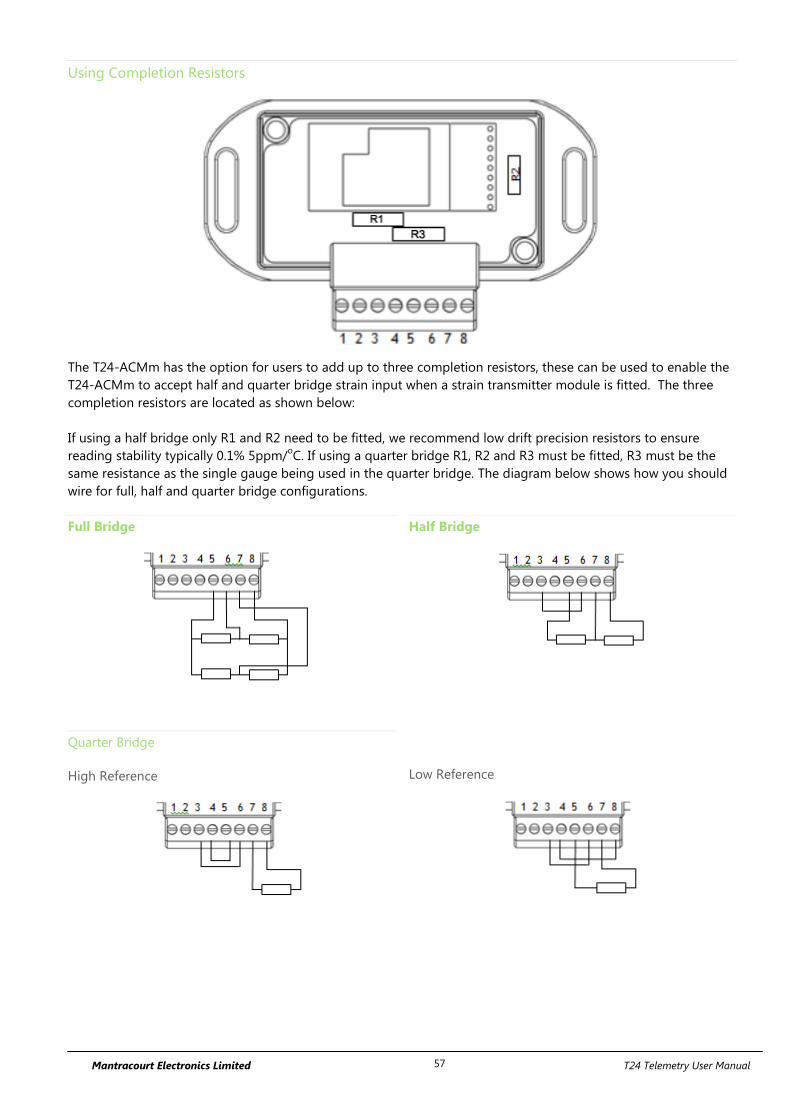
Mantracourt Electronics Limited T24 Telemetry User Manual 57
Using Completion Resistors
The T24-ACMm has the option for users to add up to three completion resistors, these can be used to enable the
T24-ACMm to accept half and quarter bridge strain input when a strain transmitter module is fitted. The three
completion resistors are located as shown below:
If using a half bridge only R1 and R2 need to be fitted, we recommend low drift precision resistors to ensure
reading stability typically 0.1% 5ppm/oC. If using a quarter bridge R1, R2 and R3 must be fitted, R3 must be the
same resistance as the single gauge being used in the quarter bridge. The diagram below shows how you should
wire for full, half and quarter bridge configurations.
Full Bridge
Half Bridge
Quarter Bridge
High Reference
Low Reference
Mantracourt Electronics Limited T24 Telemetry User Manual 58
Shield Connections (All Enclosures)
We recommend the following rules to determine whether there should be a connection between the transmitter
module shield and the sensor chassis or cable:
1. If the sensor is remote to the transmitter module and the screen of the signal cable is NOT connected to the
sensor chassis then the cable screen should be connected to the transmitter module shield connection.
2. If the sensor is remote to the transmitter module and the screen of the signal cable IS connected to the sensor
chassis then the cable screen should be NOT connected to the transmitter module shield connection.
3. If the transmitter module is integral to the sensor or mounted very close and the module is mounted on a metal
chassis then the answer to whether the transmitter module shield connection should be connected to the metal
chassis is a matter of experimentation. This connection must be as short as possible. The T24 Toolkit can be used
to chart the signal levels and tests should be undertaken to determine whether there is a better radio signal with
or without the shield/chassis connection. The quality of the measured reading should also be looked at. In cases
where the shield/chassis connection makes no difference to the radio signal or the reading quality then the
connection should be made.
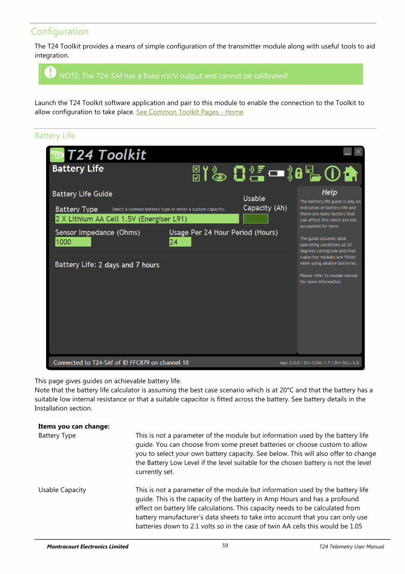
Mantracourt Electronics Limited T24 Telemetry User Manual 59
Configuration
The T24 Toolkit provides a means of simple configuration of the transmitter module along with useful tools to aid
integration.
NOTE: The T24-SAf has a fixed nV/V output and cannot be calibrated!
Launch the T24 Toolkit software application and pair to this module to enable the connection to the Toolkit to
allow configuration to take place. See Common Toolkit Pages - Home
Battery Life
This page gives guides on achievable battery life.
Note that the battery life calculator is assuming the best case scenario which is at 20°C and that the battery has a
suitable low internal resistance or that a suitable capacitor is fitted across the battery. See battery details in the
Installation section.
Items you can change:
Battery Type This is not a parameter of the module but information used by the battery life
guide. You can choose from some preset batteries or choose custom to allow
you to select your own battery capacity. See below. This will also offer to change
the Battery Low Level if the level suitable for the chosen battery is not the level
currently set.
Usable Capacity This is not a parameter of the module but information used by the battery life
guide. This is the capacity of the battery in Amp Hours and has a profound
effect on battery life calculations. This capacity needs to be calculated from
battery manufacturer’s data sheets to take into account that you can only use
batteries down to 2.1 volts so in the case of twin AA cells this would be 1.05

Mantracourt Electronics Limited T24 Telemetry User Manual 60
volts.
Generally the usable capacity will not be as high as that advertised by the
battery manufacturer. Temperature and internal resistance of the battery are not
taken into account in the guide.
Sensor Impedance This is only available for certain transmitter modules. This is not a parameter of
the module but information used by the battery life guide. Enter the resistance
of the connected strain gauge in Ohms.
Usage Per 24 Hour Period Enter the number of hours per 24 hour period that the T24-SAf will be turned
on and communicating.
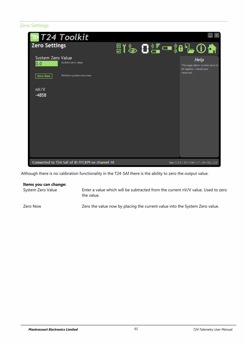
Mantracourt Electronics Limited T24 Telemetry User Manual 61
Zero Settings
Although there is no calibration functionality in the T24-SAf there is the ability to zero the output value.
Items you can change:
System Zero Value Enter a value which will be subtracted from the current nV/V value. Used to zero
the value.
Zero Now Zero the value now by placing the current value into the System Zero value.
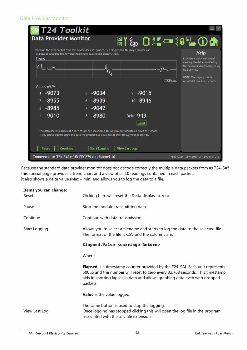
Mantracourt Electronics Limited T24 Telemetry User Manual 62
Data Provider Monitor
Because the standard data provider monitor does not decode correctly the multiple data packets from as T24-SAf
this special page provides a trend chart and a view of all 10 readings contained in each packet.
It also shows a delta value (Max – min) and allows you to log the data to a file.
Items you can change:
Reset Clicking here will reset the Delta display to zero.
Pause Stop the module transmitting data.
Continue Continue with data transmission.
Start Logging Allows you to select a filename and starts to log the data to the selected file.
The format of the file is CSV and the columns are:
Elapsed,Value <carriage Return>
Where
Elapsed is a timestamp counter provided by the T24-SAf. Each unit represents
500uS and the number will reset to zero every 32.768 seconds. This timestamp
aids in spotting lapses in data and allows graphing data even with dropped
packets.
Value is the value logged.
The same button is used to stop the logging.
View Last Log Once logging has stopped clicking this will open the log file in the program
associated with the .csv file extension.
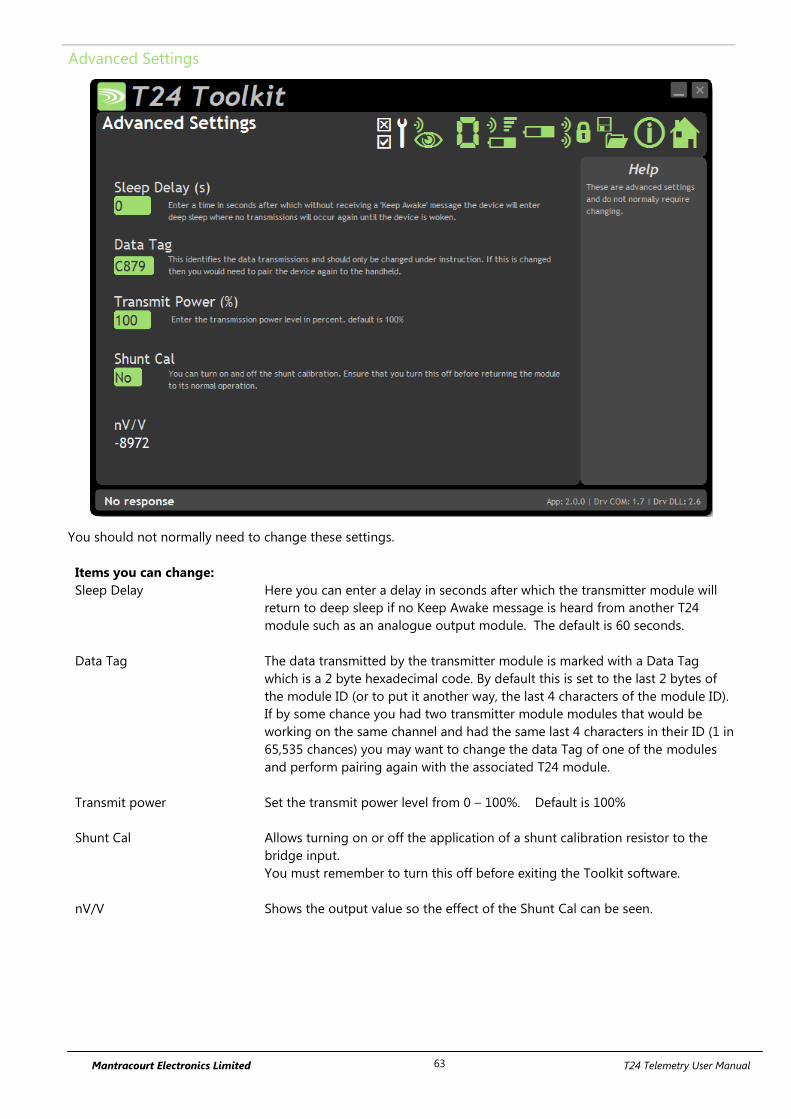
Mantracourt Electronics Limited T24 Telemetry User Manual 63
Advanced Settings
You should not normally need to change these settings.
Items you can change:
Sleep Delay Here you can enter a delay in seconds after which the transmitter module will
return to deep sleep if no Keep Awake message is heard from another T24
module such as an analogue output module. The default is 60 seconds.
Data Tag The data transmitted by the transmitter module is marked with a Data Tag
which is a 2 byte hexadecimal code. By default this is set to the last 2 bytes of
the module ID (or to put it another way, the last 4 characters of the module ID).
If by some chance you had two transmitter module modules that would be
working on the same channel and had the same last 4 characters in their ID (1 in
65,535 chances) you may want to change the data Tag of one of the modules
and perform pairing again with the associated T24 module.
Transmit power Set the transmit power level from 0 – 100%. Default is 100%
Shunt Cal Allows turning on or off the application of a shunt calibration resistor to the
bridge input.
You must remember to turn this off before exiting the Toolkit software.
nV/V Shows the output value so the effect of the Shunt Cal can be seen.
Mantracourt Electronics Limited T24 Telemetry User Manual 64
Enclosure & Mounting
This module is available in a number of different enclosure types. Locate your module and follow the link to view
dimensional and mounting information for that particular enclosure.
T24-SAfe, T24-SAfi
These OEM modules are bare PCB modules. Please see Appendix A – Enclosures & Mounting – OEM Transmitter
Modules for more information.
T24-ACM-SAf
This module is fitted inside our large enclosure. Please see Appendix A – Enclosures & Mounting – ACM for more
information.
T24-ACMi-SAf
This module is fitted inside our medium enclosure. Please see Appendix A – Enclosures & Mounting – ACMi for
more information.
T24-ACMm-SAf
This module is fitted inside our small enclosure. Please see Appendix A – Enclosures & Mounting – ACMm for
more information.
Antennas
T24-SAfi
This module uses an integrated chip antenna. See Appendix B – Antennas – Internal Chip Antenna
T24-SAfe
Only the T24-SAfe module allows for the fitting of external antennas. The choices are:
T24-ANTA PCB Antenna See Appendix B – Antennas – T24-ANTA
T24-ANTB Dipole Antenna See Appendix B – Antennas – T24-ANTB
T24-ANTC Dipole Antenna Swivel See Appendix B – Antennas – T24-ANTC
T24-ANTD Puck Antenna SMA See Appendix B – Antennas – T24-ANTD
T24-ANTE Puck Antenna UFL See Appendix B – Antennas – T24-ANTE
T24-ACM-SAf, T24-ACMi-SAf, T24-ACMm-SAf
These modules have the antenna already fitted inside the enclosure so there are no specific mounting
requirements.
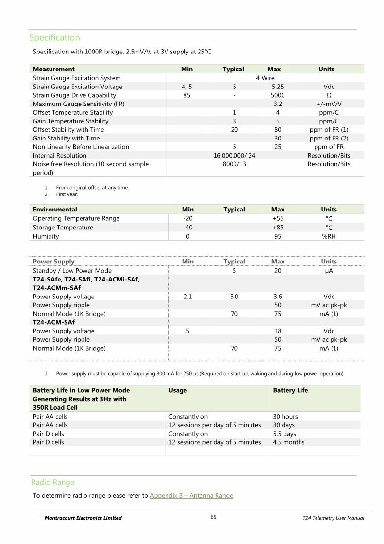
Mantracourt Electronics Limited T24 Telemetry User Manual 65
Specification
Specification with 1000R bridge, 2.5mV/V, at 3V supply at 25°C
Measurement Min Typical Max Units
Strain Gauge Excitation System 4 Wire
Strain Gauge Excitation Voltage 4. 5 5 5.25 Vdc
Strain Gauge Drive Capability 85 - 5000 Ω
Maximum Gauge Sensitivity (FR) 3.2 +/-mV/V
Offset Temperature Stability 1 4 ppm/C
Gain Temperature Stability 3 5 ppm/C
Offset Stability with Time 20 80 ppm of FR (1)
Gain Stability with Time 30 ppm of FR (2)
Non Linearity Before Linearization 5 25 ppm of FR
Internal Resolution 16,000,000/ 24 Resolution/Bits
Noise free Resolution (10 second sample
period)
8000/13 Resolution/Bits
1. From original offset at any time.
2. First year.
Environmental Min Typical Max Units
Operating Temperature Range -20 +55 °C
Storage Temperature -40 +85 °C
Humidity 0 95 %RH
Power Supply Min Typical Max Units
Standby / Low Power Mode 5 20 µA
T24-SAfe, T24-SAfi, T24-ACMi-SAf,
T24-ACMm-SAf
Power Supply voltage 2.1 3.0 3.6 Vdc
Power Supply ripple 50 mV ac pk-pk
Normal Mode (1K Bridge) 70 75 mA (1)
T24-ACM-SAf
Power Supply voltage 5 18 Vdc
Power Supply ripple 50 mV ac pk-pk
Normal Mode (1K Bridge) 70 75 mA (1)
1. Power supply must be capable of supplying 300 mA for 250 µs (Required on start up, waking and during low power operation)
Battery Life in Low Power Mode
Generating Results at 3Hz with
350R Load Cell
Usage Battery Life
Pair AA cells Constantly on 30 hours
Pair AA cells 12 sessions per day of 5 minutes 30 days
Pair D cells Constantly on 5.5 days
Pair D cells 12 sessions per day of 5 minutes 4.5 months
Radio Range
To determine radio range please refer to Appendix B – Antenna Range
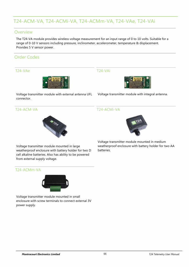
Mantracourt Electronics Limited T24 Telemetry User Manual 66
T24-ACM-VA, T24-ACMi-VA, T24-ACMm-VA, T24-VAe, T24-VAi
Overview
The T24-VA module provides wireless voltage measurement for an input range of 0 to 10 volts. Suitable for a
range of 0-10 V sensors including pressure, inclinometer, accelerometer, temperature & displacement.
Provides 5 V sensor power.
Order Codes
T24-VAe
Voltage transmitter module with external antenna UFL
connector.
T24-VAi
Voltage transmitter module with integral antenna.
T24-ACM-VA
Voltage transmitter module mounted in large
weatherproof enclosure with battery holder for two D
cell alkaline batteries. Also has ability to be powered
from external supply voltage.
T24-ACMi-VA
Voltage transmitter module mounted in medium
weatherproof enclosure with battery holder for two AA
batteries.
T24-ACMm-VA
Voltage transmitter module mounted in small
enclosure with screw terminals to connect external 3V
power supply.
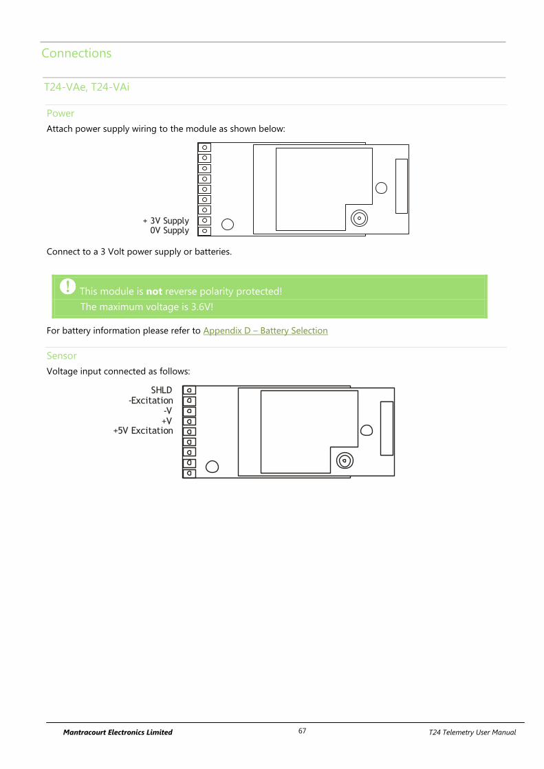
Mantracourt Electronics Limited T24 Telemetry User Manual 67
Connections
T24-VAe, T24-VAi
Power
Attach power supply wiring to the module as shown below:
+ 3V Supply0V Supply
Connect to a 3 Volt power supply or batteries.
This module is not reverse polarity protected!
The maximum voltage is 3.6V!
For battery information please refer to Appendix D – Battery Selection
Sensor
Voltage input connected as follows:
-V+V
-ExcitationSHLD
+5V Excitation
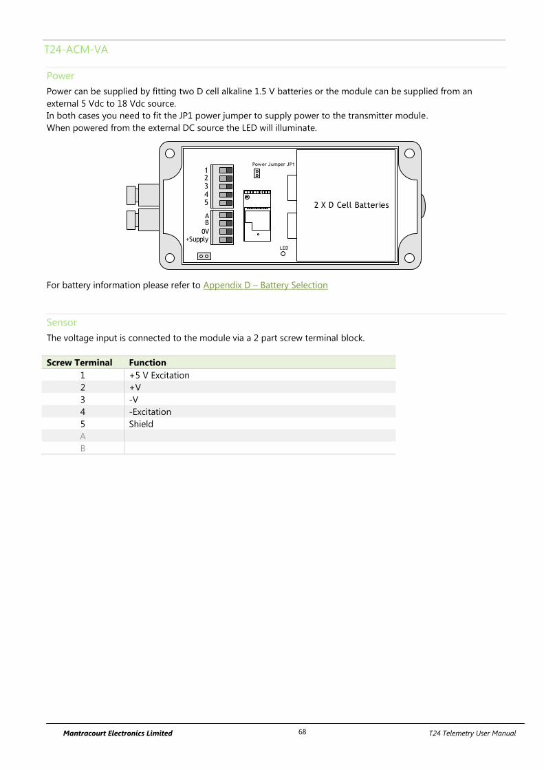
Mantracourt Electronics Limited T24 Telemetry User Manual 68
T24-ACM-VA
Power
Power can be supplied by fitting two D cell alkaline 1.5 V batteries or the module can be supplied from an
external 5 Vdc to 18 Vdc source.
In both cases you need to fit the JP1 power jumper to supply power to the transmitter module.
When powered from the external DC source the LED will illuminate.
2 X D Cell Batteries
AB
0V+Supply
12345
Power Jumper JP1
LED
For battery information please refer to Appendix D – Battery Selection
Sensor
The voltage input is connected to the module via a 2 part screw terminal block.
Screw Terminal Function
1 +5 V Excitation
2 +V
3 -V
4 -Excitation
5 Shield
A
B

Mantracourt Electronics Limited T24 Telemetry User Manual 69
T24-ACMi-VA
Power
The enclosure is designed to accept two AA batteries. Maximum voltage 1.8V per cell.
For battery information please refer to Appendix D – Battery Selection
Sensor
The input connections are accessed by lifting the right hand cover plate, this plate incorporates the T24-ACMi
Antenna; take extra care when re-assembling that the grey UHF cable is attached to the antenna socket.
Screw Terminal Function
1 Shield
2 -Excitation
3 -V in
4 +V in
5 + 5 V Excitation
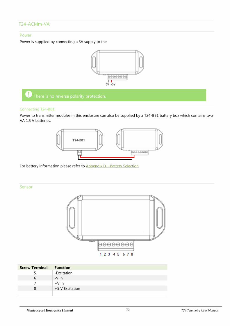
Mantracourt Electronics Limited T24 Telemetry User Manual 70
T24-ACMm-VA
Power
Power is supplied by connecting a 3V supply to the
There is no reverse polarity protection.
Connecting T24-BB1
Power to transmitter modules in this enclosure can also be supplied by a T24-BB1 battery box which contains two
AA 1.5 V batteries.
For battery information please refer to Appendix D – Battery Selection
Sensor
Screw Terminal Function
5 -Excitation
6 -V in
7 +V in
8 +5 V Excitation
Mantracourt Electronics Limited T24 Telemetry User Manual 71
Shield Connections (All Enclosures)
We recommend the following rules to determine whether there should be a connection between the transmitter
module shield and the sensor chassis or cable:
1. If the sensor is remote to the transmitter module and the screen of the signal cable is NOT connected to the
sensor chassis then the cable screen should be connected to the transmitter module shield connection.
2. If the sensor is remote to the transmitter module and the screen of the signal cable IS connected to the sensor
chassis then the cable screen should be NOT connected to the transmitter module shield connection.
3. If the transmitter module is integral to the sensor or mounted very close and the module is mounted on a metal
chassis then the answer to whether the transmitter module shield connection should be connected to the metal
chassis is a matter of experimentation. This connection must be as short as possible. The T24 Toolkit can be used
to chart the signal levels and tests should be undertaken to determine whether there is a better radio signal with
or without the shield/chassis connection. The quality of the measured reading should also be looked at. In cases
where the shield/chassis connection makes no difference to the radio signal or the reading quality then the
connection should be made.
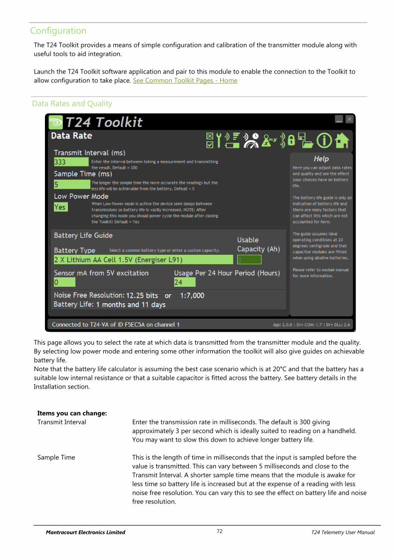
Mantracourt Electronics Limited T24 Telemetry User Manual 72
Configuration
The T24 Toolkit provides a means of simple configuration and calibration of the transmitter module along with
useful tools to aid integration.
Launch the T24 Toolkit software application and pair to this module to enable the connection to the Toolkit to
allow configuration to take place. See Common Toolkit Pages - Home
Data Rates and Quality
This page allows you to select the rate at which data is transmitted from the transmitter module and the quality.
By selecting low power mode and entering some other information the toolkit will also give guides on achievable
battery life.
Note that the battery life calculator is assuming the best case scenario which is at 20°C and that the battery has a
suitable low internal resistance or that a suitable capacitor is fitted across the battery. See battery details in the
Installation section.
Items you can change:
Transmit Interval Enter the transmission rate in milliseconds. The default is 300 giving
approximately 3 per second which is ideally suited to reading on a handheld.
You may want to slow this down to achieve longer battery life.
Sample Time This is the length of time in milliseconds that the input is sampled before the
value is transmitted. This can vary between 5 milliseconds and close to the
Transmit Interval. A shorter sample time means that the module is awake for
less time so battery life is increased but at the expense of a reading with less
noise free resolution. You can vary this to see the effect on battery life and noise
free resolution.

Mantracourt Electronics Limited T24 Telemetry User Manual 73
Low Power Mode Unless the transmitter module is non battery powered this should be set to Yes.
In between transmissions the transmitter module will enter sleep mode which,
for some modules such as the strain gauge transmitter module, will have a
massive effect on battery life.
A Reason for not using Low Power Mode would be if using the module in a
Master-Slave arrangement with PC for example.
Battery Type This is not a parameter of the module but information used by the battery life
guide. You can choose from some preset batteries or choose custom to allow
you to select your own battery capacity. See below. This will also offer to change
the Battery Low Level if the level suitable for the chosen battery is not the level
currently set.
Usable Capacity This is not a parameter of the module but information used by the battery life
guide. This is the capacity of the battery in Amp Hours and has a profound
effect on battery life calculations. This capacity needs to be calculated from
battery manufacturer’s data sheets to take into account that you can only use
batteries down to 2.1 volts so in the case of twin AA cells this would be 1.05
volts.
Generally the usable capacity will not be as high as that advertised by the
battery manufacturer. Temperature and internal resistance of the battery are not
taken into account in the guide.
Sensor Resistance This is only available for certain transmitter modules. This is not a parameter of
the module but information used by the battery life guide. Enter the resistance
of the connected strain gauge in Ohms.
Usage Per 24 Hour Period Enter the number of hours per 24 hour period that the T24-HS handheld will be
turned on and communicating with a transmitter module.

Mantracourt Electronics Limited T24 Telemetry User Manual 74
Calibration
Here you can calibrate the transmitter module and set a system zero if required.
This simple page allows semi-automated calibration where you can apply known inputs to calibrate.
This calibration includes linearization and is automatically applied.
See later for By Cert and Advanced page where you can adjust individual gains and offsets.
Calibration Process
Decide on how many points you will calibrate over.
Decide what voltage inputs will be applied (in ascending order) at each point.
Enter the actual input (in the required units) that you want the module to read at each point.
Now proceed to apply each input in turn (allowing a settle time) and click the Acquire button at that point.
You can now apply the next input and click Acquire until all the points are completed.
The voltage input must be ascending through each calibration point.
The bottom of the page shows the Input Value and the Calibrated Value. Once the second point has been
acquired this Calibrated Value should display the actual calibrated value.
Items you can change:
Number of Calibration Points Enter the number of points you wish to calibrate over. In its simplest form you
could select two for a linear calibration.
For more complex calibrations which include linearization select three to nine
points.
Point 1 - 9 For each point enter the engineering unit value that you want the transmitter
module to report at the applied input. i.e. 1.67

Mantracourt Electronics Limited T24 Telemetry User Manual 75
Acquire 1 - 9 Click this button when the input has been applied and the reading has been
allowed to settle. This will acquire the reading and allow you to move to the
next points. You will be able to click the button again to re-acquire.
Start Again Click here to restart the calibration.
System Zero Once calibrated you may want to remove a fixed system value. In the case of a
strain gauge input this may be the weight of a sling, shackle, load bed etc.
Apply the required input and click here to set the system zero. The current input
will be removed from subsequent readings so that the reading will be zero.
To edit this value manually click the Advanced button.
System Zero is stored in non-volatile memory in the transmitter module.
By Cert. You can click the By Cert button to calibrate against a sensor calibration sheet.
You just need to enter the input values and associated engineering unit
required output value of at least 2 points.
This will take you to a different screen.
Advanced Clicking the advanced button will allow you to edit the gains and offsets for
each available calibration point. This will take you to a different screen.

Mantracourt Electronics Limited T24 Telemetry User Manual 76
Calibration by Certificate
In some circumstances it may not be possible to apply inputs in which case the calibration can be entered
manually from a calibration table.
Items you can change:
Number of Calibration Points Enter the number of points you wish to calibrate over. In its simplest form you
could select two for a linear calibration.
For more complex calibrations which include linearization select three to nine
points.
Input Points 1 – 9
Enter the % input point for which you will specify a required engineering output
value. These modules are factory calibrated where 0% = 0 V and 100% = 10 V
Engineering Units 1 - 9 Enter the required engineering unit output for the specified input value
Calibrate Click this button to calculate and update the module calibration
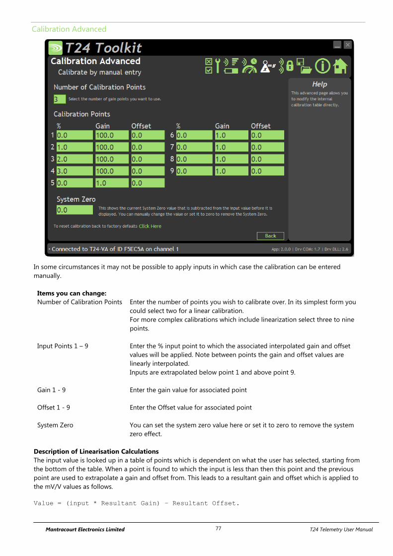
Mantracourt Electronics Limited T24 Telemetry User Manual 77
Calibration Advanced
In some circumstances it may not be possible to apply inputs in which case the calibration can be entered
manually.
Items you can change:
Number of Calibration Points Enter the number of points you wish to calibrate over. In its simplest form you
could select two for a linear calibration.
For more complex calibrations which include linearization select three to nine
points.
Input Points 1 – 9
Enter the % input point to which the associated interpolated gain and offset
values will be applied. Note between points the gain and offset values are
linearly interpolated.
Inputs are extrapolated below point 1 and above point 9.
Gain 1 - 9 Enter the gain value for associated point
Offset 1 - 9 Enter the Offset value for associated point
System Zero You can set the system zero value here or set it to zero to remove the system
zero effect.
Description of Linearisation Calculations
The input value is looked up in a table of points which is dependent on what the user has selected, starting from
the bottom of the table. When a point is found to which the input is less than then this point and the previous
point are used to extrapolate a gain and offset from. This leads to a resultant gain and offset which is applied to
the mV/V values as follows.
Value = (input * Resultant Gain) – Resultant Offset.
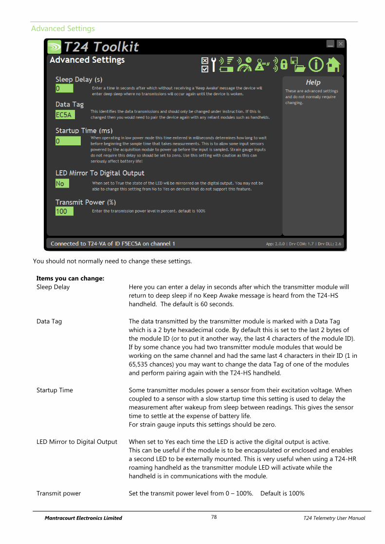
Mantracourt Electronics Limited T24 Telemetry User Manual 78
Advanced Settings
You should not normally need to change these settings.
Items you can change:
Sleep Delay Here you can enter a delay in seconds after which the transmitter module will
return to deep sleep if no Keep Awake message is heard from the T24-HS
handheld. The default is 60 seconds.
Data Tag The data transmitted by the transmitter module is marked with a Data Tag
which is a 2 byte hexadecimal code. By default this is set to the last 2 bytes of
the module ID (or to put it another way, the last 4 characters of the module ID).
If by some chance you had two transmitter module modules that would be
working on the same channel and had the same last 4 characters in their ID (1 in
65,535 chances) you may want to change the data Tag of one of the modules
and perform pairing again with the T24-HS handheld.
Startup Time Some transmitter modules power a sensor from their excitation voltage. When
coupled to a sensor with a slow startup time this setting is used to delay the
measurement after wakeup from sleep between readings. This gives the sensor
time to settle at the expense of battery life.
For strain gauge inputs this settings should be zero.
LED Mirror to Digital Output When set to Yes each time the LED is active the digital output is active.
This can be useful if the module is to be encapsulated or enclosed and enables
a second LED to be externally mounted. This is very useful when using a T24-HR
roaming handheld as the transmitter module LED will activate while the
handheld is in communications with the module.
Transmit power Set the transmit power level from 0 – 100%. Default is 100%
Mantracourt Electronics Limited T24 Telemetry User Manual 79
Enclosure & Mounting
This module is available in a number of different enclosure types. Locate your module and follow the link to view
dimensional and mounting information for that particular enclosure.
T24-VAe, T24-VAi
These OEM modules are bare PCB modules. Please see Appendix A – Enclosures & Mounting – OEM Transmitter
Modules for more information.
T24-ACM-VA
This module is fitted inside our large enclosure. Please see Appendix A – Enclosures & Mounting – ACM for more
information.
T24-ACMi-VA
This module is fitted inside our medium enclosure. Please see Appendix A – Enclosures & Mounting – ACMi for
more information.
T24-ACMm-VA
This module is fitted inside our small enclosure. Please see Appendix A – Enclosures & Mounting – ACMm for
more information.

Mantracourt Electronics Limited T24 Telemetry User Manual 80
Antennas
T24-VAi
This module uses an integrated chip antenna. See Appendix B – Antennas – Internal Chip Antenna
T24-VAe
Only the T24-VAe module allows for the fitting of external antennas. The choices are:
T24-ANTA PCB Antenna See Appendix B – Antennas – T24-ANTA
T24-ANTB Dipole Antenna See Appendix B – Antennas – T24-ANTB
T24-ANTC Dipole Antenna Articulated See Appendix B – Antennas – T24-ANTC
T24-ANTD Puck Antenna SMA See Appendix B – Antennas – T24-ANTD
T24-ANTE Puck Antenna UFL See Appendix B – Antennas – T24-ANTE
T24-ACM-VA, T24-ACMi-VA, T24-ACMm-VA
These modules have the antenna already fitted inside the enclosure so there are no specific mounting
requirements.
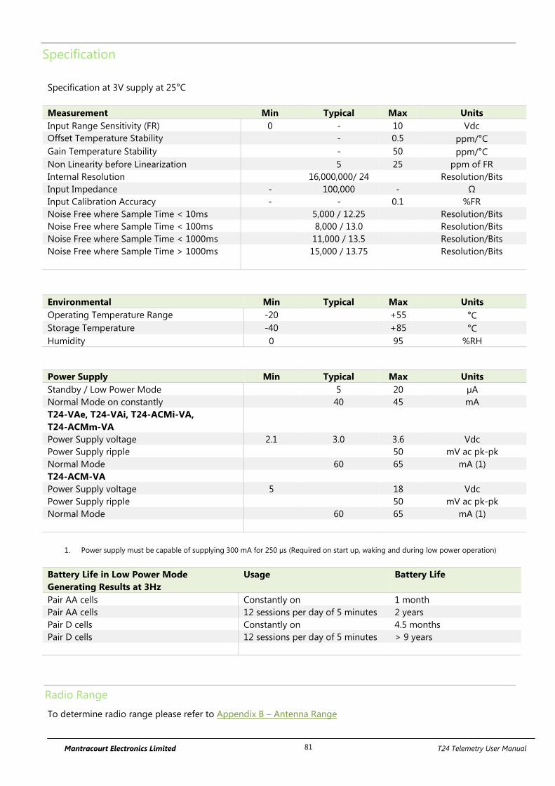
Mantracourt Electronics Limited T24 Telemetry User Manual 81
Specification
Specification at 3V supply at 25°C
Measurement Min Typical Max Units
Input Range Sensitivity (FR) 0 - 10 Vdc
Offset Temperature Stability - 0.5 ppm/°C
Gain Temperature Stability - 50 ppm/°C
Non Linearity before Linearization 5 25 ppm of FR
Internal Resolution 16,000,000/ 24 Resolution/Bits
Input Impedance - 100,000 - Ω
Input Calibration Accuracy - - 0.1 %FR
Noise Free where Sample Time < 10ms 5,000 / 12.25 Resolution/Bits
Noise Free where Sample Time < 100ms 8,000 / 13.0 Resolution/Bits
Noise Free where Sample Time < 1000ms 11,000 / 13.5 Resolution/Bits
Noise Free where Sample Time > 1000ms 15,000 / 13.75 Resolution/Bits
Environmental Min Typical Max Units
Operating Temperature Range -20 +55 °C
Storage Temperature -40 +85 °C
Humidity 0 95 %RH
Power Supply Min Typical Max Units
Standby / Low Power Mode 5 20 µA
Normal Mode on constantly 40 45 mA
T24-VAe, T24-VAi, T24-ACMi-VA,
T24-ACMm-VA
Power Supply voltage 2.1 3.0 3.6 Vdc
Power Supply ripple 50 mV ac pk-pk
Normal Mode 60 65 mA (1)
T24-ACM-VA
Power Supply voltage 5 18 Vdc
Power Supply ripple 50 mV ac pk-pk
Normal Mode 60 65 mA (1)
1. Power supply must be capable of supplying 300 mA for 250 µs (Required on start up, waking and during low power operation)
Battery Life in Low Power Mode
Generating Results at 3Hz
Usage Battery Life
Pair AA cells Constantly on 1 month
Pair AA cells 12 sessions per day of 5 minutes 2 years
Pair D cells Constantly on 4.5 months
Pair D cells 12 sessions per day of 5 minutes > 9 years
Radio Range
To determine radio range please refer to Appendix B – Antenna Range
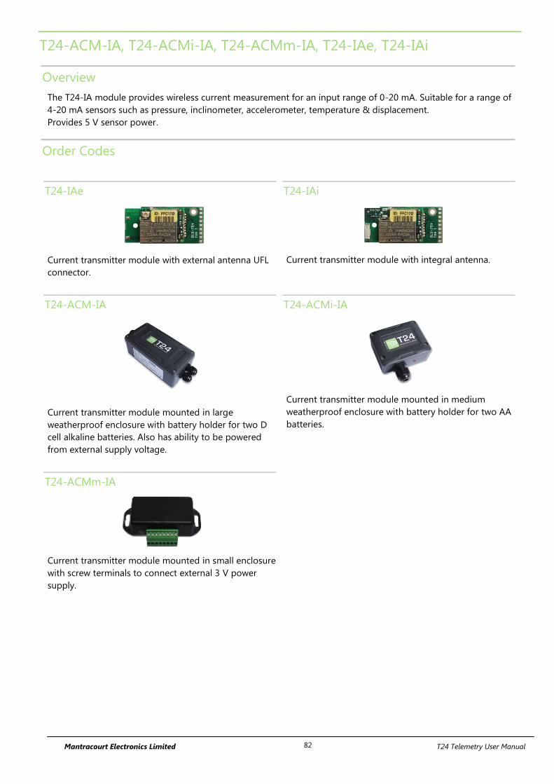
Mantracourt Electronics Limited T24 Telemetry User Manual 82
T24-ACM-IA, T24-ACMi-IA, T24-ACMm-IA, T24-IAe, T24-IAi
Overview
The T24-IA module provides wireless current measurement for an input range of 0-20 mA. Suitable for a range of
4-20 mA sensors such as pressure, inclinometer, accelerometer, temperature & displacement.
Provides 5 V sensor power.
Order Codes
T24-IAe
Current transmitter module with external antenna UFL
connector.
T24-IAi
Current transmitter module with integral antenna.
T24-ACM-IA
Current transmitter module mounted in large
weatherproof enclosure with battery holder for two D
cell alkaline batteries. Also has ability to be powered
from external supply voltage.
T24-ACMi-IA
Current transmitter module mounted in medium
weatherproof enclosure with battery holder for two AA
batteries.
T24-ACMm-IA
Current transmitter module mounted in small enclosure
with screw terminals to connect external 3 V power
supply.
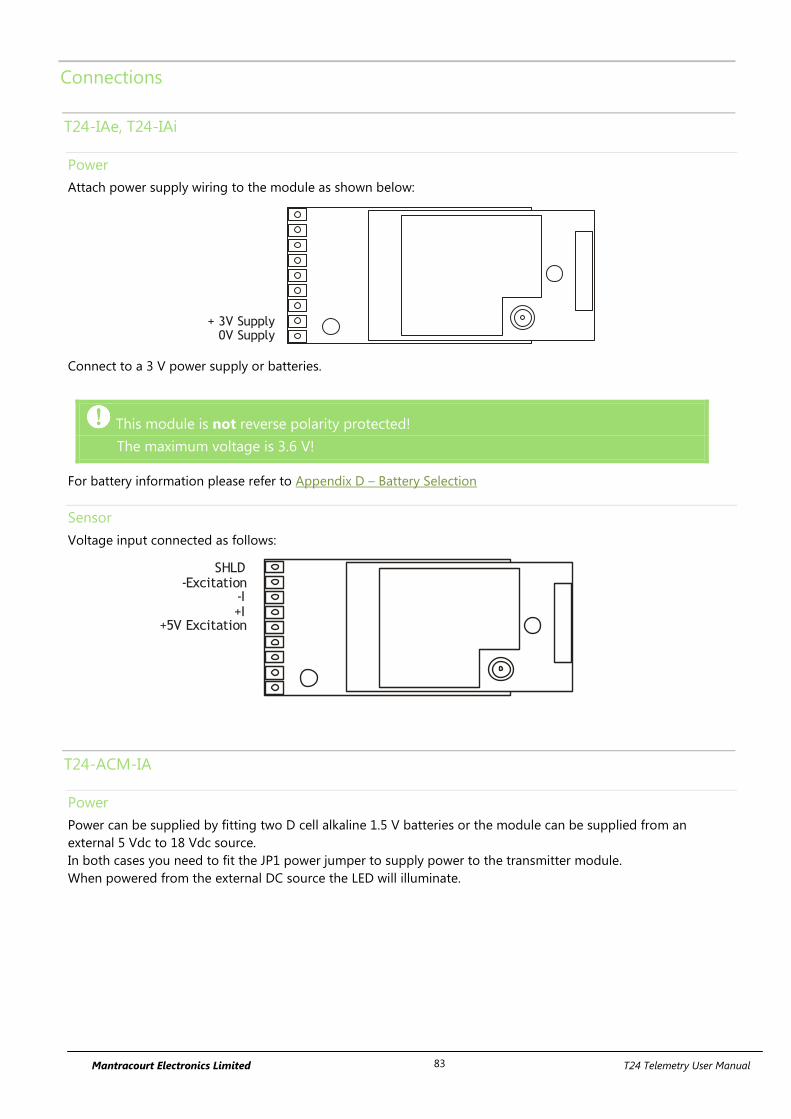
Mantracourt Electronics Limited T24 Telemetry User Manual 83
Connections
T24-IAe, T24-IAi
Power
Attach power supply wiring to the module as shown below:
+ 3V Supply0V Supply
Connect to a 3 V power supply or batteries.
This module is not reverse polarity protected!
The maximum voltage is 3.6 V!
For battery information please refer to Appendix D – Battery Selection
Sensor
Voltage input connected as follows:
-I+I
-ExcitationSHLD
+5V Excitation
T24-ACM-IA
Power
Power can be supplied by fitting two D cell alkaline 1.5 V batteries or the module can be supplied from an
external 5 Vdc to 18 Vdc source.
In both cases you need to fit the JP1 power jumper to supply power to the transmitter module.
When powered from the external DC source the LED will illuminate.
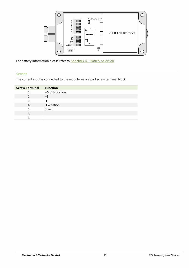
Mantracourt Electronics Limited T24 Telemetry User Manual 84
2 X D Cell Batteries
AB
0V+Supply
12345
Power Jumper JP1
LED
For battery information please refer to Appendix D – Battery Selection
Sensor
The current input is connected to the module via a 2 part screw terminal block.
Screw Terminal Function
1 +5 V Excitation
2 +I
3 -I
4 -Excitation
5 Shield
A
B

Mantracourt Electronics Limited T24 Telemetry User Manual 85
T24-ACMi-IA
Power
The enclosure is designed to accept two AA batteries. Maximum voltage 1.8 V per cell.
For battery information please refer to Appendix D – Battery Selection
Sensor
The input connections are accessed by lifting the right hand cover plate, this plate incorporates the T24-ACMi
Antenna; take extra care when re-assembling that the grey UHF cable is attached to the antenna socket.
Screw Terminal Function
1 Shield
2 -Excitation
3 -I in
4 +I in
5 + 5 V Excitation
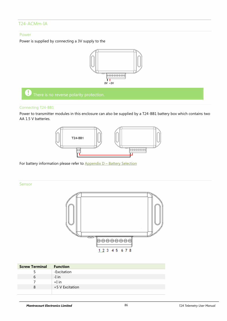
Mantracourt Electronics Limited T24 Telemetry User Manual 86
T24-ACMm-IA
Power
Power is supplied by connecting a 3V supply to the
There is no reverse polarity protection.
Connecting T24-BB1
Power to transmitter modules in this enclosure can also be supplied by a T24-BB1 battery box which contains two
AA 1.5 V batteries.
For battery information please refer to Appendix D – Battery Selection
Sensor
Screw Terminal Function
5 -Excitation
6 -I in
7 +I in
8 +5 V Excitation

Mantracourt Electronics Limited T24 Telemetry User Manual 87
Shield Connections (All Enclosures)
We recommend the following rules to determine whether there should be a connection between the transmitter
module shield and the sensor chassis or cable:
1. If the sensor is remote to the transmitter module and the screen of the signal cable is NOT connected to the
sensor chassis then the cable screen should be connected to the transmitter module shield connection.
2. If the sensor is remote to the transmitter module and the screen of the signal cable IS connected to the sensor
chassis then the cable screen should be NOT connected to the transmitter module shield connection.
3. If the transmitter module is integral to the sensor or mounted very close and the module is mounted on a metal
chassis then the answer to whether the transmitter module shield connection should be connected to the metal
chassis is a matter of experimentation. This connection must be as short as possible. The T24 Toolkit can be used
to chart the signal levels and tests should be undertaken to determine whether there is a better radio signal with
or without the shield/chassis connection. The quality of the measured reading should also be looked at. In cases
where the shield/chassis connection makes no difference to the radio signal or the reading quality then the
connection should be made.
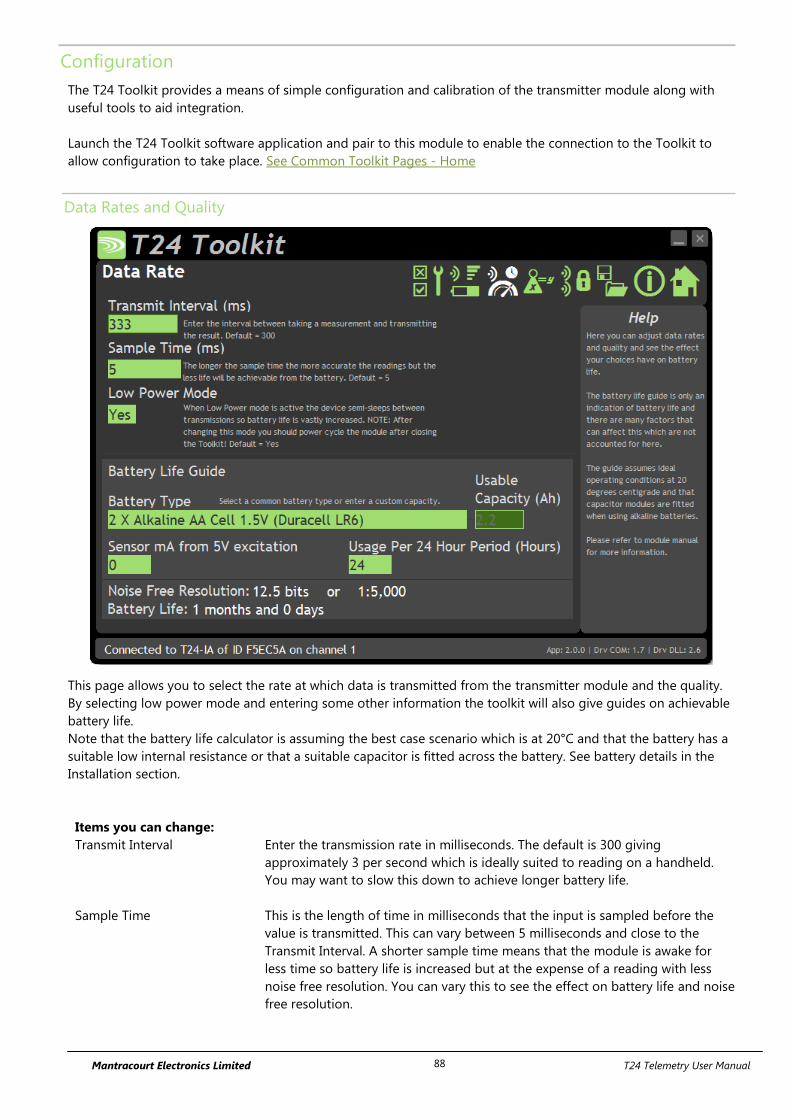
Mantracourt Electronics Limited T24 Telemetry User Manual 88
Configuration
The T24 Toolkit provides a means of simple configuration and calibration of the transmitter module along with
useful tools to aid integration.
Launch the T24 Toolkit software application and pair to this module to enable the connection to the Toolkit to
allow configuration to take place. See Common Toolkit Pages - Home
Data Rates and Quality
This page allows you to select the rate at which data is transmitted from the transmitter module and the quality.
By selecting low power mode and entering some other information the toolkit will also give guides on achievable
battery life.
Note that the battery life calculator is assuming the best case scenario which is at 20°C and that the battery has a
suitable low internal resistance or that a suitable capacitor is fitted across the battery. See battery details in the
Installation section.
Items you can change:
Transmit Interval Enter the transmission rate in milliseconds. The default is 300 giving
approximately 3 per second which is ideally suited to reading on a handheld.
You may want to slow this down to achieve longer battery life.
Sample Time This is the length of time in milliseconds that the input is sampled before the
value is transmitted. This can vary between 5 milliseconds and close to the
Transmit Interval. A shorter sample time means that the module is awake for
less time so battery life is increased but at the expense of a reading with less
noise free resolution. You can vary this to see the effect on battery life and noise
free resolution.
Mantracourt Electronics Limited T24 Telemetry User Manual 89
Low Power Mode Unless the transmitter module is non battery powered this should be set to Yes.
In between transmissions the transmitter module will enter sleep mode which,
for some modules such as the strain gauge transmitter module, will have a
massive effect on battery life.
A Reason for not using Low Power Mode would be if using the module in a
Master-Slave arrangement with PC for example.
Battery Type This is not a parameter of the module but information used by the battery life
guide. You can choose from some preset batteries or choose custom to allow
you to select your own battery capacity. See below. This will also offer to change
the Battery Low Level if the level suitable for the chosen battery is not the level
currently set.
Usable Capacity This is not a parameter of the module but information used by the battery life
guide. This is the capacity of the battery in Amp Hours and has a profound
effect on battery life calculations. This capacity needs to be calculated from
battery manufacturer’s data sheets to take into account that you can only use
batteries down to 2.1 volts so in the case of twin AA cells this would be 1.05
volts.
Generally the usable capacity will not be as high as that advertised by the
battery manufacturer. Temperature and internal resistance of the battery are not
taken into account in the guide.
Sensor Resistance This is only available for certain transmitter modules. This is not a parameter of
the module but information used by the battery life guide. Enter the resistance
of the connected strain gauge in Ohms.
Usage Per 24 Hour Period Enter the number of hours per 24 hour period that the T24-HS handheld will be
turned on and communicating with a transmitter module.
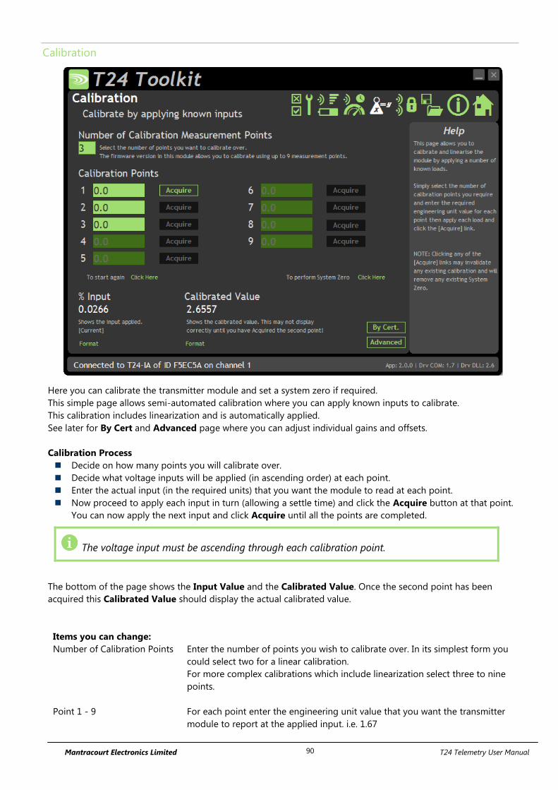
Mantracourt Electronics Limited T24 Telemetry User Manual 90
Calibration
Here you can calibrate the transmitter module and set a system zero if required.
This simple page allows semi-automated calibration where you can apply known inputs to calibrate.
This calibration includes linearization and is automatically applied.
See later for By Cert and Advanced page where you can adjust individual gains and offsets.
Calibration Process
Decide on how many points you will calibrate over.
Decide what voltage inputs will be applied (in ascending order) at each point.
Enter the actual input (in the required units) that you want the module to read at each point.
Now proceed to apply each input in turn (allowing a settle time) and click the Acquire button at that point.
You can now apply the next input and click Acquire until all the points are completed.
The voltage input must be ascending through each calibration point.
The bottom of the page shows the Input Value and the Calibrated Value. Once the second point has been
acquired this Calibrated Value should display the actual calibrated value.
Items you can change:
Number of Calibration Points Enter the number of points you wish to calibrate over. In its simplest form you
could select two for a linear calibration.
For more complex calibrations which include linearization select three to nine
points.
Point 1 - 9 For each point enter the engineering unit value that you want the transmitter
module to report at the applied input. i.e. 1.67
Mantracourt Electronics Limited T24 Telemetry User Manual 91
Acquire 1 - 9 Click this button when the input has been applied and the reading has been
allowed to settle. This will acquire the reading and allow you to move to the
next points. You will be able to click the button again to re-acquire.
Start Again Click here to restart the calibration.
System Zero Once calibrated you may want to remove a fixed system value. In the case of a
strain gauge input this may be the weight of a sling, shackle, load bed etc.
Apply the required input and click here to set the system zero. The current input
will be removed from subsequent readings so that the reading will be zero.
To edit this value manually click the Advanced button.
System Zero is stored in non-volatile memory in the transmitter module.
By Cert. You can click the By Cert button to calibrate against a sensor calibration sheet.
You just need to enter the input values and associated engineering unit
required output value of at least 2 points.
This will take you to a different screen.
Advanced Clicking the advanced button will allow you to edit the gains and offsets for
each available calibration point. This will take you to a different screen.
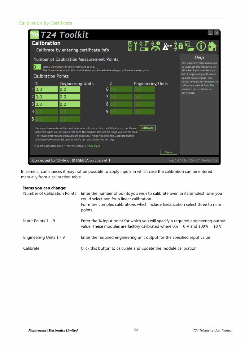
Mantracourt Electronics Limited T24 Telemetry User Manual 92
Calibration by Certificate
In some circumstances it may not be possible to apply inputs in which case the calibration can be entered
manually from a calibration table.
Items you can change:
Number of Calibration Points Enter the number of points you wish to calibrate over. In its simplest form you
could select two for a linear calibration.
For more complex calibrations which include linearization select three to nine
points.
Input Points 1 – 9
Enter the % input point for which you will specify a required engineering output
value. These modules are factory calibrated where 0% = 0 V and 100% = 10 V
Engineering Units 1 - 9 Enter the required engineering unit output for the specified input value
Calibrate Click this button to calculate and update the module calibration
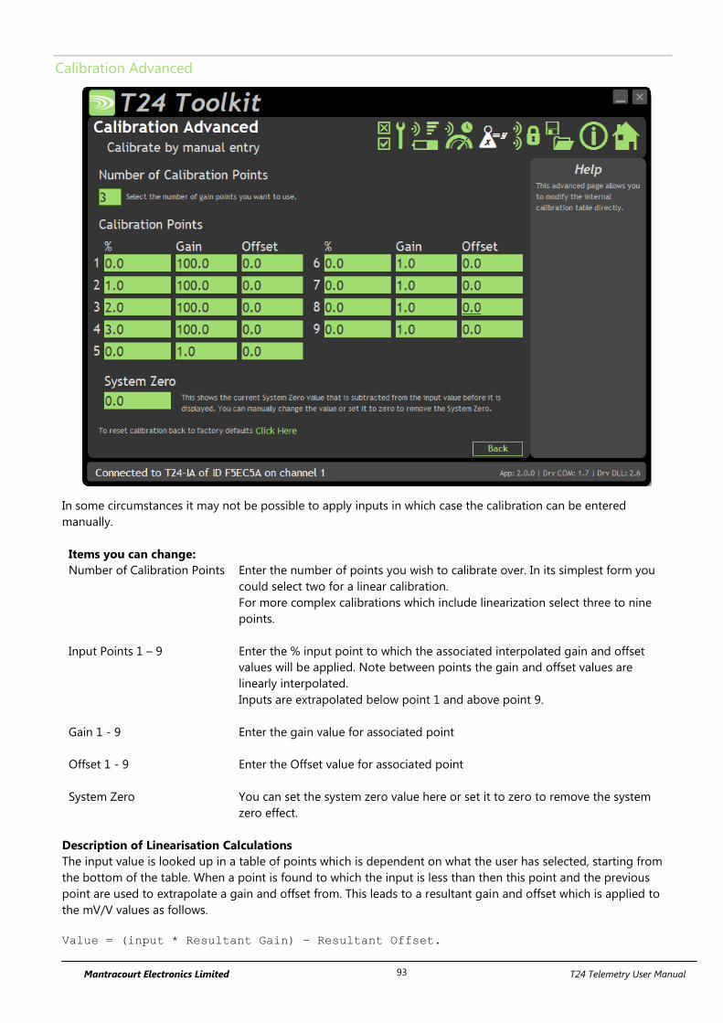
Mantracourt Electronics Limited T24 Telemetry User Manual 93
Calibration Advanced
In some circumstances it may not be possible to apply inputs in which case the calibration can be entered
manually.
Items you can change:
Number of Calibration Points Enter the number of points you wish to calibrate over. In its simplest form you
could select two for a linear calibration.
For more complex calibrations which include linearization select three to nine
points.
Input Points 1 – 9
Enter the % input point to which the associated interpolated gain and offset
values will be applied. Note between points the gain and offset values are
linearly interpolated.
Inputs are extrapolated below point 1 and above point 9.
Gain 1 - 9 Enter the gain value for associated point
Offset 1 - 9 Enter the Offset value for associated point
System Zero You can set the system zero value here or set it to zero to remove the system
zero effect.
Description of Linearisation Calculations
The input value is looked up in a table of points which is dependent on what the user has selected, starting from
the bottom of the table. When a point is found to which the input is less than then this point and the previous
point are used to extrapolate a gain and offset from. This leads to a resultant gain and offset which is applied to
the mV/V values as follows.
Value = (input * Resultant Gain) – Resultant Offset.

Mantracourt Electronics Limited T24 Telemetry User Manual 94
Advanced Settings
You should not normally need to change these settings.
Items you can change:
Sleep Delay Here you can enter a delay in seconds after which the transmitter module will
return to deep sleep if no Keep Awake message is heard from the T24-HS
handheld. The default is 60 seconds.
Data Tag The data transmitted by the transmitter module is marked with a Data Tag
which is a 2 byte hexadecimal code. By default this is set to the last 2 bytes of
the module ID (or to put it another way, the last 4 characters of the module ID).
If by some chance you had two transmitter module modules that would be
working on the same channel and had the same last 4 characters in their ID (1 in
65,535 chances) you may want to change the data Tag of one of the modules
and perform pairing again with the T24-HS handheld.
Startup Time Some transmitter modules power a sensor from their excitation voltage. When
coupled to a sensor with a slow startup time this setting is used to delay the
measurement after wakeup from sleep between readings. This gives the sensor
time to settle at the expense of battery life.
For strain gauge inputs this settings should be zero.
LED Mirror to Digital Output When set to Yes each time the LED is active the digital output is active.
This can be useful if the module is to be encapsulated or enclosed and enables
a second LED to be externally mounted. This is very useful when using a T24-HR
roaming handheld as the transmitter module LED will activate while the
handheld is in communications with the module.
Transmit power Set the transmit power level from 0 – 100%. Default is 100%

Mantracourt Electronics Limited T24 Telemetry User Manual 95
Enclosure & Mounting
This module is available in a number of different enclosure types. Locate your module and follow the link to view
dimensional and mounting information for that particular enclosure.
T24-IAe, T24-IAi
These OEM modules are bare PCB modules. Please see Appendix A – Enclosures & Mounting – OEM Transmitter
Modules for more information.
T24-ACM-IA
This module is fitted inside our large enclosure. Please see Appendix A – Enclosures & Mounting – ACM for more
information.
T24-ACMi-IA
This module is fitted inside our medium enclosure. Please see Appendix A – Enclosures & Mounting – ACMi for
more information.
T24-ACMm-IA
This module is fitted inside our small enclosure. Please see Appendix A – Enclosures & Mounting – ACMm for
more information.

Mantracourt Electronics Limited T24 Telemetry User Manual 96
Antennas
T24-IAi
This module uses an integrated chip antenna. See Appendix B – Antennas – Internal Chip Antenna
T24-IAe
Only the T24-IAe module allows for the fitting of external antennas. The choices are:
T24-ANTA PCB Antenna See Appendix B – Antennas – T24-ANTA
T24-ANTB Dipole Antenna See Appendix B – Antennas – T24-ANTB
T24-ANTC Dipole Antenna Swivel See Appendix B – Antennas – T24-ANTC
T24-ANTD Puck Antenna SMA See Appendix B – Antennas – T24-ANTD
T24-ANTE Puck Antenna UFL See Appendix B – Antennas – T24-ANTE
T24-ACM-IA, T24-ACMi-IA, T24-ACMm-IA
These modules have the antenna already fitted inside the enclosure so there are no specific mounting
requirements.
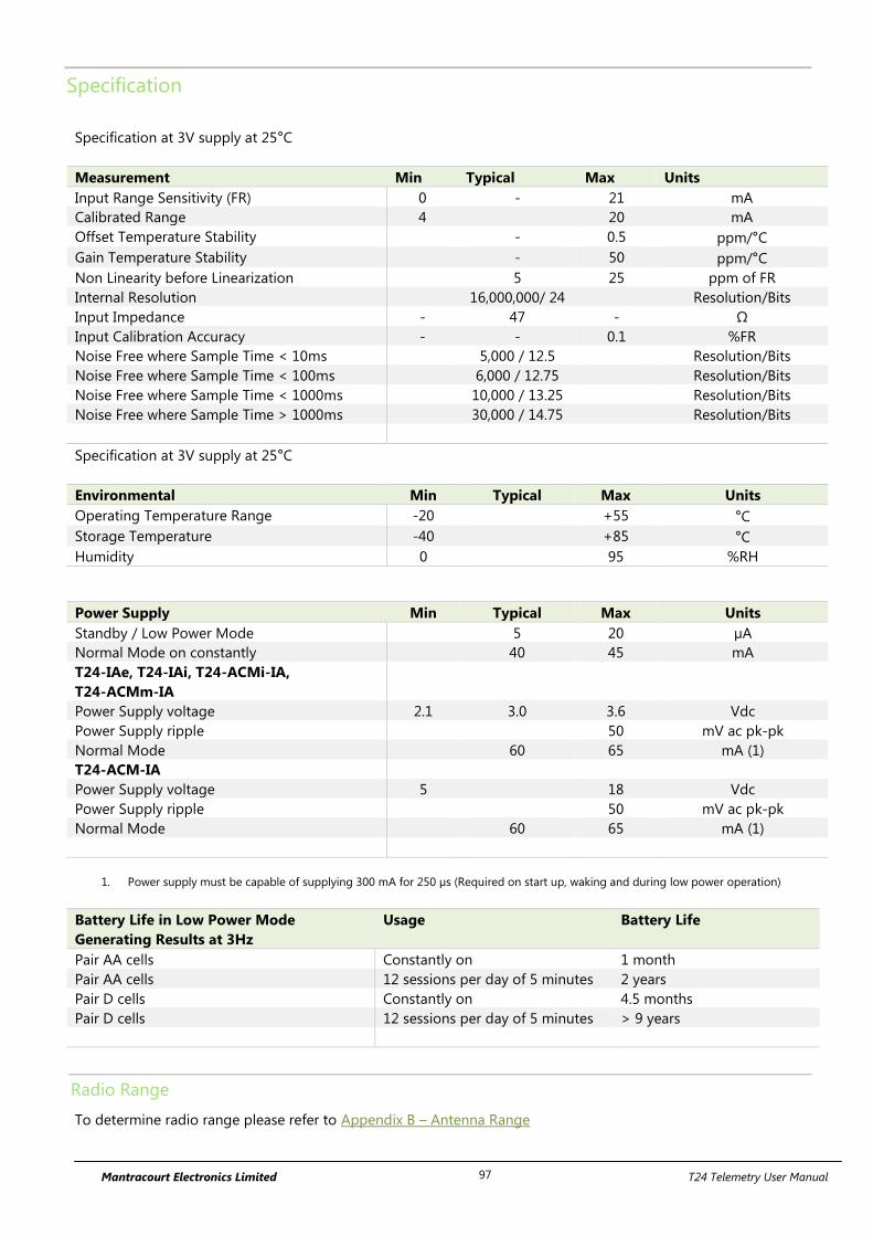
Mantracourt Electronics Limited T24 Telemetry User Manual 97
Specification
Specification at 3V supply at 25°C
Measurement Min Typical Max Units
Input Range Sensitivity (FR) 0 - 21 mA
Calibrated Range 4 20 mA
Offset Temperature Stability - 0.5 ppm/°C
Gain Temperature Stability - 50 ppm/°C
Non Linearity before Linearization 5 25 ppm of FR
Internal Resolution 16,000,000/ 24 Resolution/Bits
Input Impedance - 47 - Ω
Input Calibration Accuracy - - 0.1 %FR
Noise Free where Sample Time < 10ms 5,000 / 12.5 Resolution/Bits
Noise Free where Sample Time < 100ms 6,000 / 12.75 Resolution/Bits
Noise Free where Sample Time < 1000ms 10,000 / 13.25 Resolution/Bits
Noise Free where Sample Time > 1000ms 30,000 / 14.75 Resolution/Bits
Specification at 3V supply at 25°C
Environmental Min Typical Max Units
Operating Temperature Range -20 +55 °C
Storage Temperature -40 +85 °C
Humidity 0 95 %RH
Power Supply Min Typical Max Units
Standby / Low Power Mode 5 20 µA
Normal Mode on constantly 40 45 mA
T24-IAe, T24-IAi, T24-ACMi-IA,
T24-ACMm-IA
Power Supply voltage 2.1 3.0 3.6 Vdc
Power Supply ripple 50 mV ac pk-pk
Normal Mode 60 65 mA (1)
T24-ACM-IA
Power Supply voltage 5 18 Vdc
Power Supply ripple 50 mV ac pk-pk
Normal Mode 60 65 mA (1)
1. Power supply must be capable of supplying 300 mA for 250 µs (Required on start up, waking and during low power operation)
Battery Life in Low Power Mode
Generating Results at 3Hz
Usage Battery Life
Pair AA cells Constantly on 1 month
Pair AA cells 12 sessions per day of 5 minutes 2 years
Pair D cells Constantly on 4.5 months
Pair D cells 12 sessions per day of 5 minutes > 9 years
Radio Range
To determine radio range please refer to Appendix B – Antenna Range

Mantracourt Electronics Limited T24 Telemetry User Manual 98
T24-ACM-TA, T24-ACMi-TA, T24-ACMm-TA, T24-TAe, T24-TAi
Overview
The T24-TA temperature sensor transmitter is a high performance module designed for the collection and
processing of temperature measurements. The wireless sensor transmitter requires an external platinum
temperature sensor (Pt100 type 385).
Order Codes
T24-TAe
Temperature transmitter module with external antenna
UFL connector.
T24-TAi
Temperature transmitter module with integral antenna.
T24-ACM-TA
Temperature transmitter module mounted in large
weatherproof enclosure with battery holder for two D
cell alkaline batteries. Also has ability to be powered
from external supply voltage.
T24-ACMi-TA
Temperature transmitter module mounted in medium
weatherproof enclosure with battery holder for two AA
batteries.
T24-ACMm-TA
Temperature transmitter module mounted in small
enclosure with screw terminals to connect external 3 V
power supply.
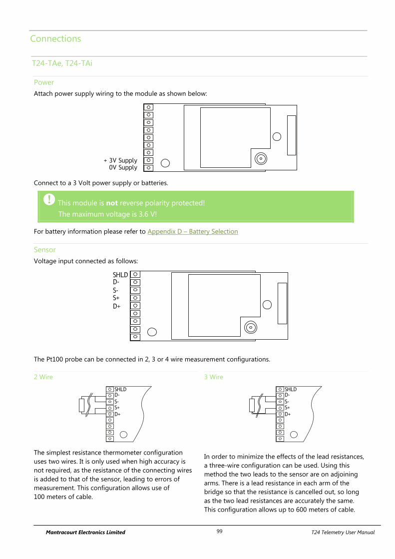
Mantracourt Electronics Limited T24 Telemetry User Manual 99
Connections
T24-TAe, T24-TAi
Power
Attach power supply wiring to the module as shown below:
+ 3V Supply0V Supply
Connect to a 3 Volt power supply or batteries.
This module is not reverse polarity protected!
The maximum voltage is 3.6 V!
For battery information please refer to Appendix D – Battery Selection
Sensor
Voltage input connected as follows:
D+
SHLDD-
S-S+
The Pt100 probe can be connected in 2, 3 or 4 wire measurement configurations.
2 Wire
D+
SHLDD-
S-S+
The simplest resistance thermometer configuration
uses two wires. It is only used when high accuracy is
not required, as the resistance of the connecting wires
is added to that of the sensor, leading to errors of
measurement. This configuration allows use of
100 meters of cable.
3 Wire
D+
SHLDD-
S-S+
In order to minimize the effects of the lead resistances,
a three-wire configuration can be used. Using this
method the two leads to the sensor are on adjoining
arms. There is a lead resistance in each arm of the
bridge so that the resistance is cancelled out, so long
as the two lead resistances are accurately the same.
This configuration allows up to 600 meters of cable.
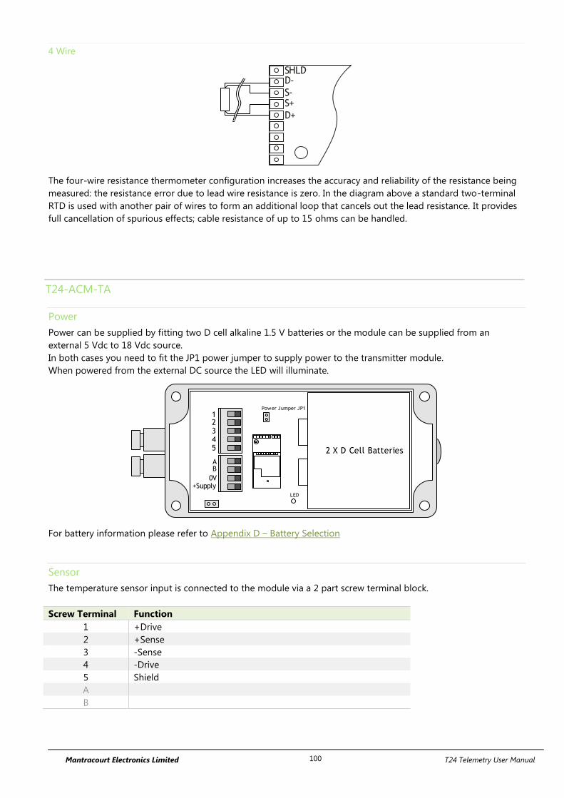
Mantracourt Electronics Limited T24 Telemetry User Manual 100
4 Wire
D+
SHLDD-
S-S+
The four-wire resistance thermometer configuration increases the accuracy and reliability of the resistance being
measured: the resistance error due to lead wire resistance is zero. In the diagram above a standard two-terminal
RTD is used with another pair of wires to form an additional loop that cancels out the lead resistance. It provides
full cancellation of spurious effects; cable resistance of up to 15 ohms can be handled.
T24-ACM-TA
Power
Power can be supplied by fitting two D cell alkaline 1.5 V batteries or the module can be supplied from an
external 5 Vdc to 18 Vdc source.
In both cases you need to fit the JP1 power jumper to supply power to the transmitter module.
When powered from the external DC source the LED will illuminate.
2 X D Cell Batteries
AB
0V+Supply
12345
Power Jumper JP1
LED
For battery information please refer to Appendix D – Battery Selection
Sensor
The temperature sensor input is connected to the module via a 2 part screw terminal block.
Screw Terminal Function
1 +Drive
2 +Sense
3 -Sense
4 -Drive
5 Shield
A
B
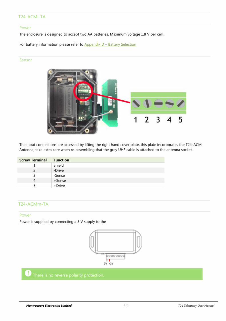
Mantracourt Electronics Limited T24 Telemetry User Manual 101
T24-ACMi-TA
Power
The enclosure is designed to accept two AA batteries. Maximum voltage 1.8 V per cell.
For battery information please refer to Appendix D – Battery Selection
Sensor
The input connections are accessed by lifting the right hand cover plate, this plate incorporates the T24-ACMi
Antenna; take extra care when re-assembling that the grey UHF cable is attached to the antenna socket.
Screw Terminal Function
1 Shield
2 -Drive
3 -Sense
4 +Sense
5 +Drive
T24-ACMm-TA
Power
Power is supplied by connecting a 3 V supply to the
There is no reverse polarity protection.
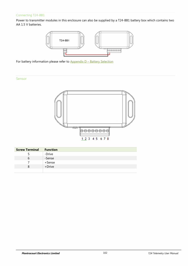
Mantracourt Electronics Limited T24 Telemetry User Manual 102
Connecting T24-BB1
Power to transmitter modules in this enclosure can also be supplied by a T24-BB1 battery box which contains two
AA 1.5 V batteries.
For battery information please refer to Appendix D – Battery Selection
Sensor
Screw Terminal Function
5 -Drive
6 -Sense
7 +Sense
8 +Drive
Mantracourt Electronics Limited T24 Telemetry User Manual 103
Shield Connections (All Enclosures)
We recommend the following rules to determine whether there should be a connection between the transmitter
module shield and the sensor chassis or cable:
1. If the sensor is remote to the transmitter module and the screen of the signal cable is NOT connected to the
sensor chassis then the cable screen should be connected to the transmitter module shield connection.
2. If the sensor is remote to the transmitter module and the screen of the signal cable IS connected to the sensor
chassis then the cable screen should be NOT connected to the transmitter module shield connection.
3. If the transmitter module is integral to the sensor or mounted very close and the module is mounted on a metal
chassis then the answer to whether the transmitter module shield connection should be connected to the metal
chassis is a matter of experimentation. This connection must be as short as possible. The T24 Toolkit can be used
to chart the signal levels and tests should be undertaken to determine whether there is a better radio signal with
or without the shield/chassis connection. The quality of the measured reading should also be looked at. In cases
where the shield/chassis connection makes no difference to the radio signal or the reading quality then the
connection should be made.
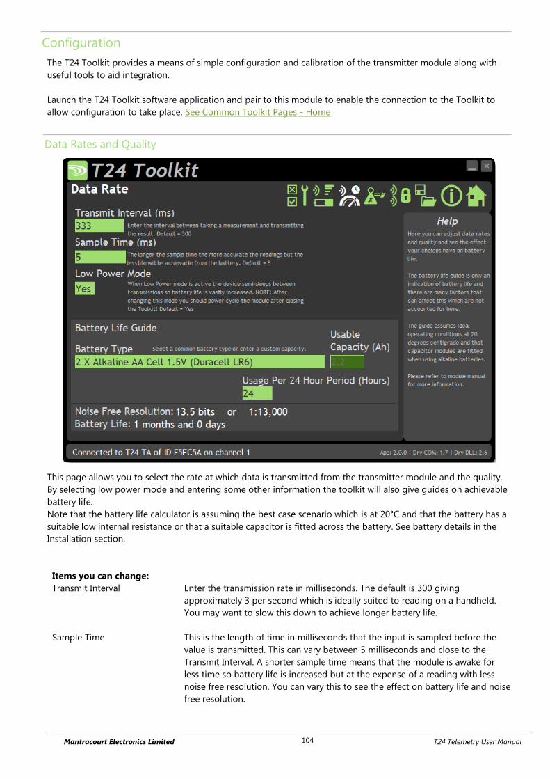
Mantracourt Electronics Limited T24 Telemetry User Manual 104
Configuration
The T24 Toolkit provides a means of simple configuration and calibration of the transmitter module along with
useful tools to aid integration.
Launch the T24 Toolkit software application and pair to this module to enable the connection to the Toolkit to
allow configuration to take place. See Common Toolkit Pages - Home
Data Rates and Quality
This page allows you to select the rate at which data is transmitted from the transmitter module and the quality.
By selecting low power mode and entering some other information the toolkit will also give guides on achievable
battery life.
Note that the battery life calculator is assuming the best case scenario which is at 20°C and that the battery has a
suitable low internal resistance or that a suitable capacitor is fitted across the battery. See battery details in the
Installation section.
Items you can change:
Transmit Interval Enter the transmission rate in milliseconds. The default is 300 giving
approximately 3 per second which is ideally suited to reading on a handheld.
You may want to slow this down to achieve longer battery life.
Sample Time This is the length of time in milliseconds that the input is sampled before the
value is transmitted. This can vary between 5 milliseconds and close to the
Transmit Interval. A shorter sample time means that the module is awake for
less time so battery life is increased but at the expense of a reading with less
noise free resolution. You can vary this to see the effect on battery life and noise
free resolution.
Mantracourt Electronics Limited T24 Telemetry User Manual 105
Low Power Mode Unless the transmitter module is non battery powered this should be set to Yes.
In between transmissions the transmitter module will enter sleep mode which,
for some modules such as the strain gauge transmitter module, will have a
massive effect on battery life.
A Reason for not using Low Power Mode would be if using the module in a
Master-Slave arrangement with PC for example.
Battery Type This is not a parameter of the module but information used by the battery life
guide. You can choose from some preset batteries or choose custom to allow
you to select your own battery capacity. See below. This will also offer to change
the Battery Low Level if the level suitable for the chosen battery is not the level
currently set.
Usable Capacity This is not a parameter of the module but information used by the battery life
guide. This is the capacity of the battery in Amp Hours and has a profound
effect on battery life calculations. This capacity needs to be calculated from
battery manufacturer’s data sheets to take into account that you can only use
batteries down to 2.1 volts so in the case of twin AA cells this would be 1.05
volts.
Generally the usable capacity will not be as high as that advertised by the
battery manufacturer. Temperature and internal resistance of the battery are not
taken into account in the guide.
Sensor Resistance This is only available for certain transmitter modules. This is not a parameter of
the module but information used by the battery life guide. Enter the resistance
of the connected strain gauge in Ohms.
Usage Per 24 Hour Period Enter the number of hours per 24 hour period that the T24-HS handheld will be
turned on and communicating with a transmitter module.
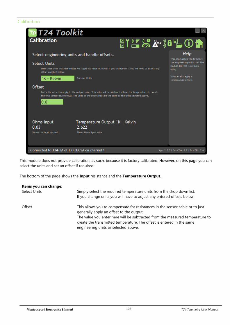
Mantracourt Electronics Limited T24 Telemetry User Manual 106
Calibration
This module does not provide calibration, as such, because it is factory calibrated. However, on this page you can
select the units and set an offset if required.
The bottom of the page shows the Input resistance and the Temperature Output.
Items you can change:
Select Units Simply select the required temperature units from the drop down list.
If you change units you will have to adjust any entered offsets below.
Offset This allows you to compensate for resistances in the sensor cable or to just
generally apply an offset to the output.
The value you enter here will be subtracted from the measured temperature to
create the transmitted temperature. The offset is entered in the same
engineering units as selected above.
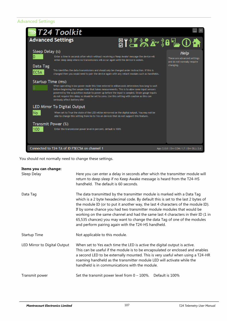
Mantracourt Electronics Limited T24 Telemetry User Manual 107
Advanced Settings
You should not normally need to change these settings.
Items you can change:
Sleep Delay Here you can enter a delay in seconds after which the transmitter module will
return to deep sleep if no Keep Awake message is heard from the T24-HS
handheld. The default is 60 seconds.
Data Tag The data transmitted by the transmitter module is marked with a Data Tag
which is a 2 byte hexadecimal code. By default this is set to the last 2 bytes of
the module ID (or to put it another way, the last 4 characters of the module ID).
If by some chance you had two transmitter module modules that would be
working on the same channel and had the same last 4 characters in their ID (1 in
65,535 chances) you may want to change the data Tag of one of the modules
and perform pairing again with the T24-HS handheld.
Startup Time Not applicable to this module.
LED Mirror to Digital Output When set to Yes each time the LED is active the digital output is active.
This can be useful if the module is to be encapsulated or enclosed and enables
a second LED to be externally mounted. This is very useful when using a T24-HR
roaming handheld as the transmitter module LED will activate while the
handheld is in communications with the module.
Transmit power Set the transmit power level from 0 – 100%. Default is 100%

Mantracourt Electronics Limited T24 Telemetry User Manual 108
Enclosure & Mounting
This module is available in a number of different enclosure types. Locate your module and follow the link to view
dimensional and mounting information for that particular enclosure.
T24-TAe, T24-TAi
These OEM modules are bare PCB modules. Please see Appendix A – Enclosures & Mounting – OEM Transmitter
Modules for more information.
T24-ACM-TA
This module is fitted inside our large enclosure. Please see Appendix A – Enclosures & Mounting – ACM for more
information.
T24-ACMi-TA
This module is fitted inside our medium enclosure. Please see Appendix A – Enclosures & Mounting – ACMi for
more information.
T24-ACMm-TA
This module is fitted inside our small enclosure. Please see Appendix A – Enclosures & Mounting – ACMm for
more information.
Antennas
T24-TAi
This module uses an integrated chip antenna. See Appendix B – Antennas – Internal Chip Antenna
T24-TAe
Only the T24-TAe module allows for the fitting of external antennas. The choices are:
T24-ANTA PCB Antenna See Appendix B – Antennas – T24-ANTA
T24-ANTB Dipole Antenna See Appendix B – Antennas – T24-ANTB
T24-ANTC Dipole Antenna Swivel See Appendix B – Antennas – T24-ANTC
T24-ANTD Puck Antenna SMA See Appendix B – Antennas – T24-ANTD
T24-ANTE Puck Antenna UFL See Appendix B – Antennas – T24-ANTE
T24-ACM-TA, T24-ACMi-TA, T24-ACMm-TA
These modules have the antenna already fitted inside the enclosure so there are no specific mounting
requirements.
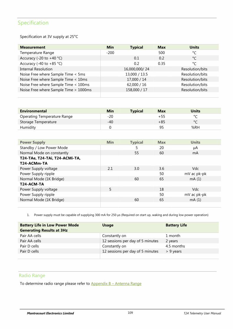
Mantracourt Electronics Limited T24 Telemetry User Manual 109
Specification
Specification at 3V supply at 25°C
Measurement Min Typical Max Units
Temperature Range -200 500 °C
Accuracy (-20 to +40 °C) 0.1 0.2 °C
Accuracy (-40 to +85 °C) 0.2 0.35 °C
Internal Resolution 16,000,000/ 24 Resolution/bits
Noise Free where Sample Time < 5ms 13,000 / 13.5 Resolution/bits
Noise Free where Sample Time < 10ms 17,000 / 14 Resolution/bits
Noise Free where Sample Time < 100ms 62,000 / 16 Resolution/bits
Noise Free where Sample Time > 1000ms 158,000 / 17 Resolution/bits
Environmental Min Typical Max Units
Operating Temperature Range -20 +55 °C
Storage Temperature -40 +85 °C
Humidity 0 95 %RH
Power Supply Min Typical Max Units
Standby / Low Power Mode 5 20 µA
Normal Mode on constantly 55 60 mA
T24-TAe, T24-TAi, T24-ACMi-TA,
T24-ACMm-TA
Power Supply voltage 2.1 3.0 3.6 Vdc
Power Supply ripple 50 mV ac pk-pk
Normal Mode (1K Bridge) 60 65 mA (1)
T24-ACM-TA
Power Supply voltage 5 18 Vdc
Power Supply ripple 50 mV ac pk-pk
Normal Mode (1K Bridge) 60 65 mA (1)
1. Power supply must be capable of supplying 300 mA for 250 µs (Required on start up, waking and during low power operation)
Battery Life in Low Power Mode
Generating Results at 3Hz
Usage Battery Life
Pair AA cells Constantly on 1 month
Pair AA cells 12 sessions per day of 5 minutes 2 years
Pair D cells Constantly on 4.5 months
Pair D cells 12 sessions per day of 5 minutes > 9 years
Radio Range
To determine radio range please refer to Appendix B – Antenna Range
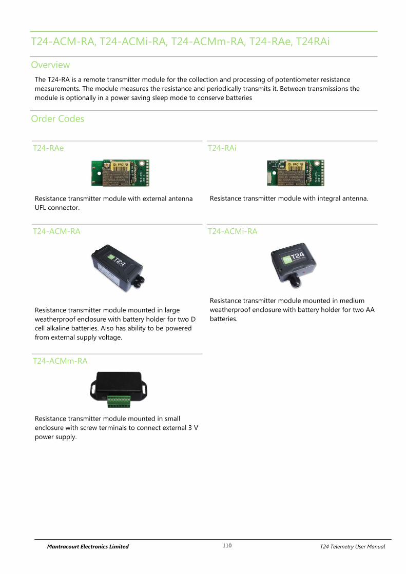
Mantracourt Electronics Limited T24 Telemetry User Manual 110
T24-ACM-RA, T24-ACMi-RA, T24-ACMm-RA, T24-RAe, T24RAi
Overview
The T24-RA is a remote transmitter module for the collection and processing of potentiometer resistance
measurements. The module measures the resistance and periodically transmits it. Between transmissions the
module is optionally in a power saving sleep mode to conserve batteries
Order Codes
T24-RAe
Resistance transmitter module with external antenna
UFL connector.
T24-RAi
Resistance transmitter module with integral antenna.
T24-ACM-RA
Resistance transmitter module mounted in large
weatherproof enclosure with battery holder for two D
cell alkaline batteries. Also has ability to be powered
from external supply voltage.
T24-ACMi-RA
Resistance transmitter module mounted in medium
weatherproof enclosure with battery holder for two AA
batteries.
T24-ACMm-RA
Resistance transmitter module mounted in small
enclosure with screw terminals to connect external 3 V
power supply.
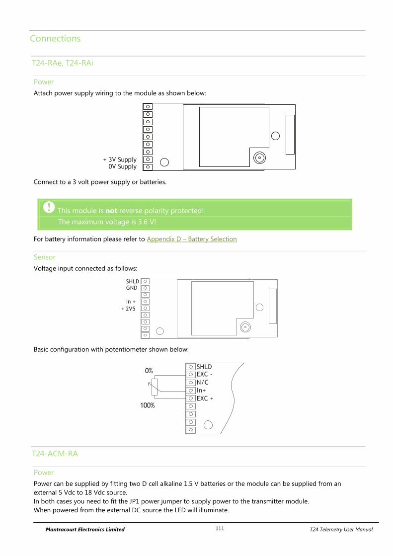
Mantracourt Electronics Limited T24 Telemetry User Manual 111
Connections
T24-RAe, T24-RAi
Power
Attach power supply wiring to the module as shown below:
+ 3V Supply0V Supply
Connect to a 3 volt power supply or batteries.
This module is not reverse polarity protected!
The maximum voltage is 3.6 V!
For battery information please refer to Appendix D – Battery Selection
Sensor
Voltage input connected as follows:
+ 2V5
SHLDGND
In +
Basic configuration with potentiometer shown below:
EXC +
SHLDEXC -
N/C
In+
0%
100%
T24-ACM-RA
Power
Power can be supplied by fitting two D cell alkaline 1.5 V batteries or the module can be supplied from an
external 5 Vdc to 18 Vdc source.
In both cases you need to fit the JP1 power jumper to supply power to the transmitter module.
When powered from the external DC source the LED will illuminate.
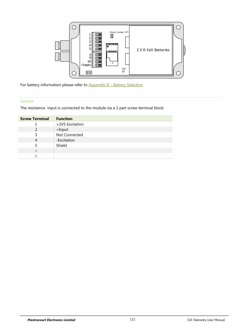
Mantracourt Electronics Limited T24 Telemetry User Manual 112
2 X D Cell Batteries
AB
0V+Supply
12345
Power Jumper JP1
LED
For battery information please refer to Appendix D – Battery Selection
Sensor
The resistance input is connected to the module via a 2 part screw terminal block.
Screw Terminal Function
1 +2V5 Excitation
2 +Input
3 Not Connected
4 -Excitation
5 Shield
A
B

Mantracourt Electronics Limited T24 Telemetry User Manual 113
T24-ACMi-RA
Power
The enclosure is designed to accept two AA batteries. Maximum voltage 1.8 V per cell.
For battery information please refer to Appendix D – Battery Selection
Sensor
The input connections are accessed by lifting the right hand cover plate, this plate incorporates the T24-ACMi
Antenna; take extra care when re-assembling that the grey UHF cable is attached to the antenna socket.
Screw Terminal Function
1 Shield
2 -Excitation
3 Not Connected
4 + Input
5 +2V5 Excitation
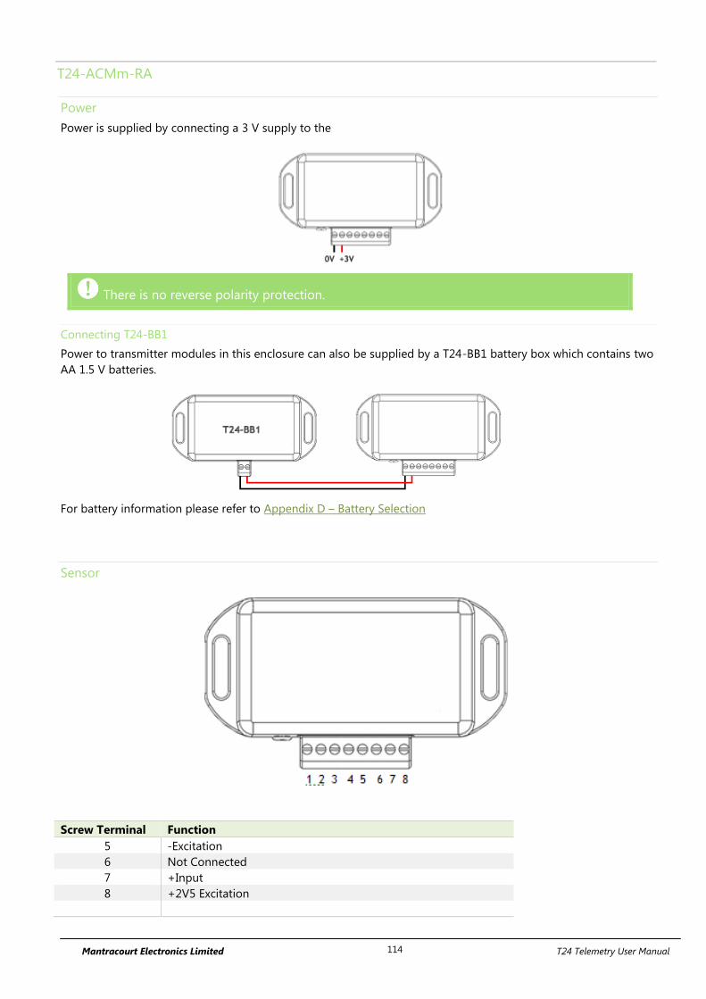
Mantracourt Electronics Limited T24 Telemetry User Manual 114
T24-ACMm-RA
Power
Power is supplied by connecting a 3 V supply to the
There is no reverse polarity protection.
Connecting T24-BB1
Power to transmitter modules in this enclosure can also be supplied by a T24-BB1 battery box which contains two
AA 1.5 V batteries.
For battery information please refer to Appendix D – Battery Selection
Sensor
Screw Terminal Function
5 -Excitation
6 Not Connected
7 +Input
8 +2V5 Excitation

Mantracourt Electronics Limited T24 Telemetry User Manual 115
Shield Connections (All Enclosures)
We recommend the following rules to determine whether there should be a connection between the transmitter
module shield and the sensor chassis or cable:
1. If the sensor is remote to the transmitter module and the screen of the signal cable is NOT connected to the
sensor chassis then the cable screen should be connected to the transmitter module shield connection.
2. If the sensor is remote to the transmitter module and the screen of the signal cable IS connected to the sensor
chassis then the cable screen should be NOT connected to the transmitter module shield connection.
3. If the transmitter module is integral to the sensor or mounted very close and the module is mounted on a metal
chassis then the answer to whether the transmitter module shield connection should be connected to the metal
chassis is a matter of experimentation. This connection must be as short as possible. The T24 Toolkit can be used
to chart the signal levels and tests should be undertaken to determine whether there is a better radio signal with
or without the shield/chassis connection. The quality of the measured reading should also be looked at. In cases
where the shield/chassis connection makes no difference to the radio signal or the reading quality then the
connection should be made.
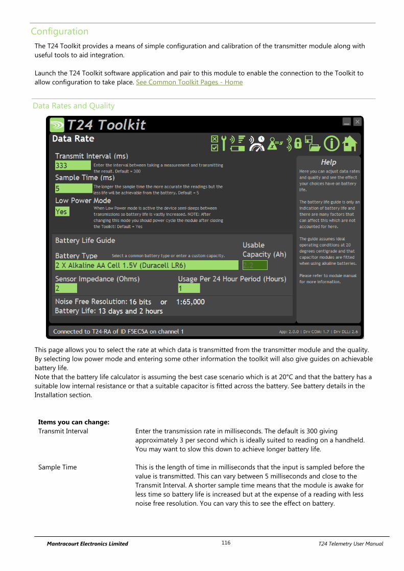
Mantracourt Electronics Limited T24 Telemetry User Manual 116
Configuration
The T24 Toolkit provides a means of simple configuration and calibration of the transmitter module along with
useful tools to aid integration.
Launch the T24 Toolkit software application and pair to this module to enable the connection to the Toolkit to
allow configuration to take place. See Common Toolkit Pages - Home
Data Rates and Quality
This page allows you to select the rate at which data is transmitted from the transmitter module and the quality.
By selecting low power mode and entering some other information the toolkit will also give guides on achievable
battery life.
Note that the battery life calculator is assuming the best case scenario which is at 20°C and that the battery has a
suitable low internal resistance or that a suitable capacitor is fitted across the battery. See battery details in the
Installation section.
Items you can change:
Transmit Interval Enter the transmission rate in milliseconds. The default is 300 giving
approximately 3 per second which is ideally suited to reading on a handheld.
You may want to slow this down to achieve longer battery life.
Sample Time This is the length of time in milliseconds that the input is sampled before the
value is transmitted. This can vary between 5 milliseconds and close to the
Transmit Interval. A shorter sample time means that the module is awake for
less time so battery life is increased but at the expense of a reading with less
noise free resolution. You can vary this to see the effect on battery.
Mantracourt Electronics Limited T24 Telemetry User Manual 117
Low Power Mode Unless the transmitter module is non battery powered this should be set to Yes.
In between transmissions the transmitter module will enter sleep mode which,
for some modules such as the strain gauge transmitter module, will have a
massive effect on battery life.
A Reason for not using Low Power Mode would be if using the module in a
Master-Slave arrangement with PC for example.
Battery Type This is not a parameter of the module but information used by the battery life
guide. You can choose from some preset batteries or choose custom to allow
you to select your own battery capacity. See below. This will also offer to change
the Battery Low Level if the level suitable for the chosen battery is not the level
currently set.
Usable Capacity This is not a parameter of the module but information used by the battery life
guide. This is the capacity of the battery in Amp Hours and has a profound
effect on battery life calculations. This capacity needs to be calculated from
battery manufacturer’s data sheets to take into account that you can only use
batteries down to 2.1 volts so in the case of twin AA cells this would be 1.05
volts.
Generally the usable capacity will not be as high as that advertised by the
battery manufacturer. Temperature and internal resistance of the battery are not
taken into account in the guide.
Sensor Impedance Ohms
Although the Impedance will vary an estimate of the average sensor impedance
will provide a good indication of battery life.
Usage Per 24 Hour Period Enter the number of hours per 24 hour period that the T24-HS handheld will be
turned on and communicating with a transmitter module.
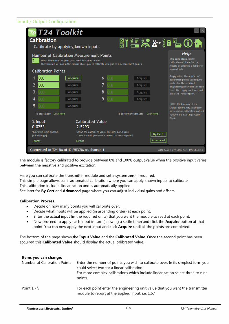
Mantracourt Electronics Limited T24 Telemetry User Manual 118
Input / Output Configuration
The module is factory calibrated to provide between 0% and 100% output value when the positive input varies
between the negative and positive excitation.
Here you can calibrate the transmitter module and set a system zero if required.
This simple page allows semi-automated calibration where you can apply known inputs to calibrate.
This calibration includes linearization and is automatically applied.
See later for By Cert and Advanced page where you can adjust individual gains and offsets.
Calibration Process
Decide on how many points you will calibrate over.
Decide what inputs will be applied (in ascending order) at each point.
Enter the actual input (in the required units) that you want the module to read at each point.
Now proceed to apply each input in turn (allowing a settle time) and click the Acquire button at that
point. You can now apply the next input and click Acquire until all the points are completed.
The bottom of the page shows the Input Value and the Calibrated Value. Once the second point has been
acquired this Calibrated Value should display the actual calibrated value.
Items you can change:
Number of Calibration Points Enter the number of points you wish to calibrate over. In its simplest form you
could select two for a linear calibration.
For more complex calibrations which include linearization select three to nine
points.
Point 1 - 9 For each point enter the engineering unit value that you want the transmitter
module to report at the applied input. i.e. 1.67
Mantracourt Electronics Limited T24 Telemetry User Manual 119
Acquire 1 - 9 Click this button when the input has been applied and the reading has been
allowed to settle. This will acquire the reading and allow you to move to the
next points. You will be able to click the button again to re-acquire.
Start Again Click here to restart the calibration.
System Zero Once calibrated you may want to remove a fixed system value. In the case of a
strain gauge input this may be the weight of a sling, shackle, load bed etc.
Apply the required input and click here to set the system zero. The current input
will be removed from subsequent readings so that the reading will be zero.
To edit this value manually click the Advanced button.
System Zero is stored in non-volatile memory in the transmitter module.
By Cert. You can click the By Cert button to calibrate against a sensor calibration sheet.
You just need to enter the input values and associated engineering unit
required output value of at least 2 points.
This will take you to a different screen.
Advanced Clicking the advanced button will allow you to edit the gains and offsets for
each available calibration point. This will take you to a different screen.
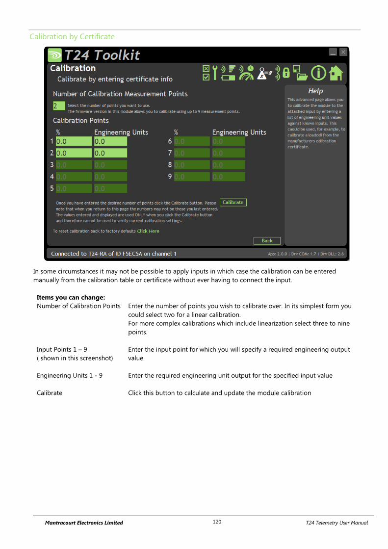
Mantracourt Electronics Limited T24 Telemetry User Manual 120
Calibration by Certificate
In some circumstances it may not be possible to apply inputs in which case the calibration can be entered
manually from the calibration table or certificate without ever having to connect the input.
Items you can change:
Number of Calibration Points Enter the number of points you wish to calibrate over. In its simplest form you
could select two for a linear calibration.
For more complex calibrations which include linearization select three to nine
points.
Input Points 1 – 9
( shown in this screenshot)
Enter the input point for which you will specify a required engineering output
value
Engineering Units 1 - 9 Enter the required engineering unit output for the specified input value
Calibrate Click this button to calculate and update the module calibration
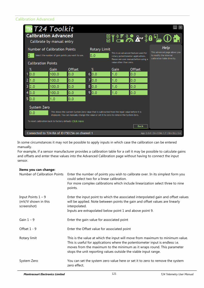
Mantracourt Electronics Limited T24 Telemetry User Manual 121
Calibration Advanced
In some circumstances it may not be possible to apply inputs in which case the calibration can be entered
manually.
For example, if a sensor manufacturer provides a calibration table for a cell it may be possible to calculate gains
and offsets and enter these values into the Advanced Calibration page without having to connect the input
sensor.
Items you can change:
Number of Calibration Points Enter the number of points you wish to calibrate over. In its simplest form you
could select two for a linear calibration.
For more complex calibrations which include linearization select three to nine
points.
Input Points 1 – 9
(mV/V shown in this
screenshot)
Enter the input point to which the associated interpolated gain and offset values
will be applied. Note between points the gain and offset values are linearly
interpolated.
Inputs are extrapolated below point 1 and above point 9.
Gain 1 – 9 Enter the gain value for associated point
Offset 1 - 9 Enter the Offset value for associated point
Rotary limit
This is the value at which the input will move from maximum to minimum value.
This is useful for applications where the potentiometer input is endless i.e.
moves from the maximum to the minimum as it wraps round. This parameter
stops the unit reporting values outside the viable input range.
System Zero You can set the system zero value here or set it to zero to remove the system
zero effect.

Mantracourt Electronics Limited T24 Telemetry User Manual 122
Description of Linearisation Calculations
The input value is looked up in a table of points which is dependent on what the user has selected, starting from
the bottom of the table. When a point is found to which the input is less than then this point and the previous
point are used to extrapolate a gain and offset from. This leads to a resultant gain and offset which is applied to
the mV/V values as follows.
Value = (input * Resultant Gain) – Resultant Offset.
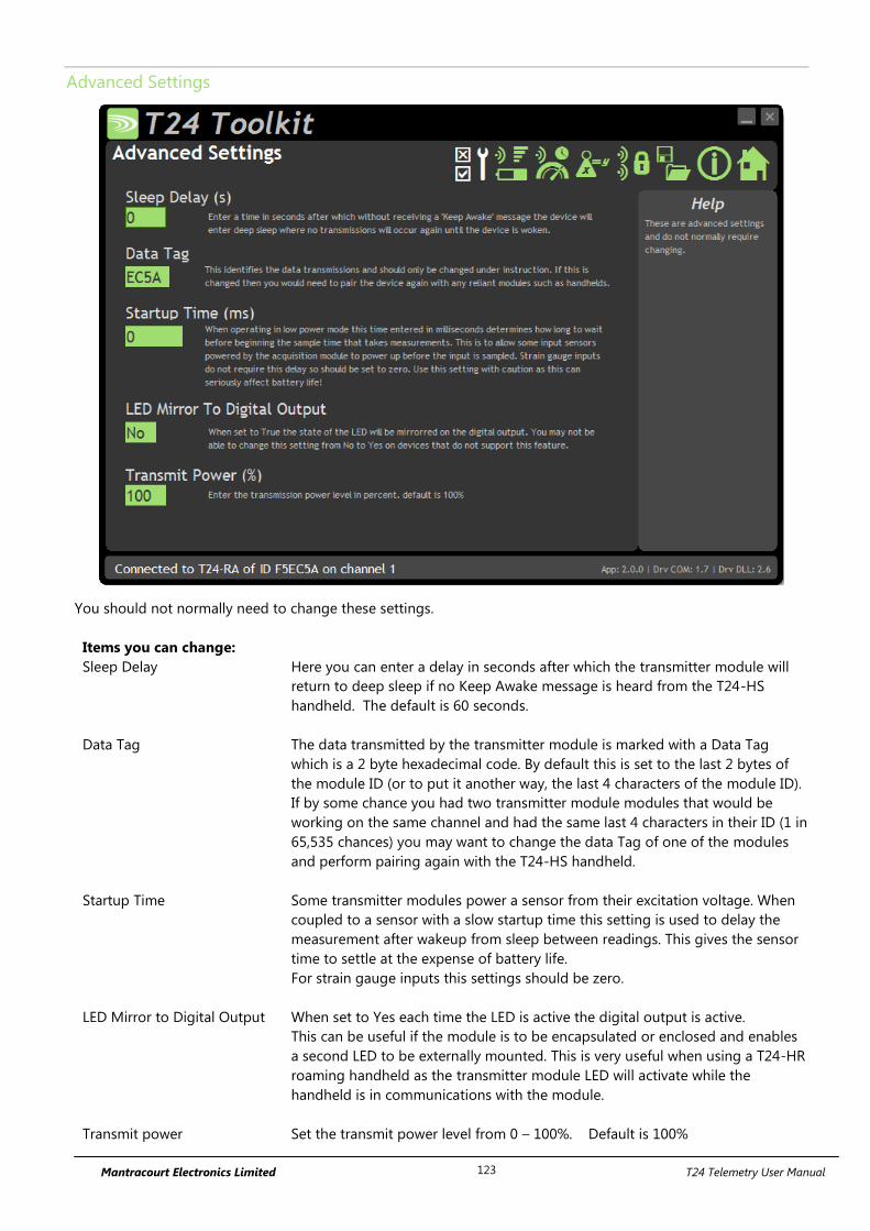
Mantracourt Electronics Limited T24 Telemetry User Manual 123
Advanced Settings
You should not normally need to change these settings.
Items you can change:
Sleep Delay Here you can enter a delay in seconds after which the transmitter module will
return to deep sleep if no Keep Awake message is heard from the T24-HS
handheld. The default is 60 seconds.
Data Tag The data transmitted by the transmitter module is marked with a Data Tag
which is a 2 byte hexadecimal code. By default this is set to the last 2 bytes of
the module ID (or to put it another way, the last 4 characters of the module ID).
If by some chance you had two transmitter module modules that would be
working on the same channel and had the same last 4 characters in their ID (1 in
65,535 chances) you may want to change the data Tag of one of the modules
and perform pairing again with the T24-HS handheld.
Startup Time Some transmitter modules power a sensor from their excitation voltage. When
coupled to a sensor with a slow startup time this setting is used to delay the
measurement after wakeup from sleep between readings. This gives the sensor
time to settle at the expense of battery life.
For strain gauge inputs this settings should be zero.
LED Mirror to Digital Output When set to Yes each time the LED is active the digital output is active.
This can be useful if the module is to be encapsulated or enclosed and enables
a second LED to be externally mounted. This is very useful when using a T24-HR
roaming handheld as the transmitter module LED will activate while the
handheld is in communications with the module.
Transmit power Set the transmit power level from 0 – 100%. Default is 100%
Mantracourt Electronics Limited T24 Telemetry User Manual 124
Enclosure & Mounting
This module is available in a number of different enclosure types. Locate your module and follow the link to view
dimensional and mounting information for that particular enclosure.
T24-RAe, T24-RAi
These OEM modules are bare PCB modules. Please see Appendix A – Enclosures & Mounting – OEM Transmitter
Modules for more information.
T24-ACM-RA
This module is fitted inside our large enclosure. Please see Appendix A – Enclosures & Mounting – ACM for more
information.
T24-ACMi-RA
This module is fitted inside our medium enclosure. Please see Appendix A – Enclosures & Mounting – ACMi for
more information.
T24-ACMm-RA
This module is fitted inside our small enclosure. Please see Appendix A – Enclosures & Mounting – ACMm for
more information.
Mantracourt Electronics Limited T24 Telemetry User Manual 125
Antennas
T24-RAi
This module uses an integrated chip antenna. See Appendix B – Antennas – Internal Chip Antenna
T24-RAe
Only the T24-RAe module allows for the fitting of external antennas. The choices are:
T24-ANTA PCB Antenna See Appendix B – Antennas – T24-ANTA
T24-ANTB Dipole Antenna See Appendix B – Antennas – T24-ANTB
T24-ANTC Dipole Antenna Swivel See Appendix B – Antennas – T24-ANTC
T24-ANTD Puck Antenna SMA See Appendix B – Antennas – T24-ANTD
T24-ANTE Puck Antenna UFL See Appendix B – Antennas – T24-ANTE
T24-ACM-RA, T24-ACMi-RA, T24-ACMm-RA
These modules have the antenna already fitted inside the enclosure so there are no specific mounting
requirements.
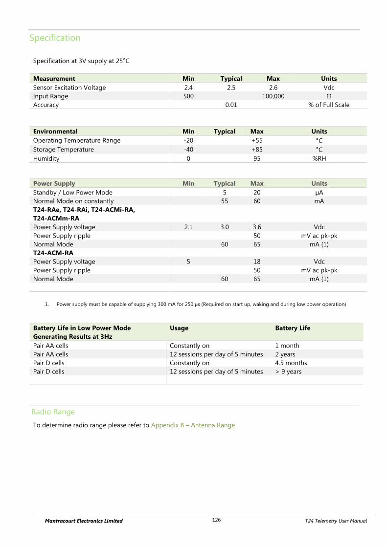
Mantracourt Electronics Limited T24 Telemetry User Manual 126
Specification
Specification at 3V supply at 25°C
Measurement Min Typical Max Units
Sensor Excitation Voltage 2.4 2.5 2.6 Vdc
Input Range 500 100,000 Ω
Accuracy 0.01 % of Full Scale
Environmental Min Typical Max Units
Operating Temperature Range -20 +55 °C
Storage Temperature -40 +85 °C
Humidity 0 95 %RH
Power Supply Min Typical Max Units
Standby / Low Power Mode 5 20 µA
Normal Mode on constantly 55 60 mA
T24-RAe, T24-RAi, T24-ACMi-RA,
T24-ACMm-RA
Power Supply voltage 2.1 3.0 3.6 Vdc
Power Supply ripple 50 mV ac pk-pk
Normal Mode 60 65 mA (1)
T24-ACM-RA
Power Supply voltage 5 18 Vdc
Power Supply ripple 50 mV ac pk-pk
Normal Mode 60 65 mA (1)
1. Power supply must be capable of supplying 300 mA for 250 µs (Required on start up, waking and during low power operation)
Battery Life in Low Power Mode
Generating Results at 3Hz
Usage Battery Life
Pair AA cells Constantly on 1 month
Pair AA cells 12 sessions per day of 5 minutes 2 years
Pair D cells Constantly on 4.5 months
Pair D cells 12 sessions per day of 5 minutes > 9 years
Radio Range
To determine radio range please refer to Appendix B – Antenna Range
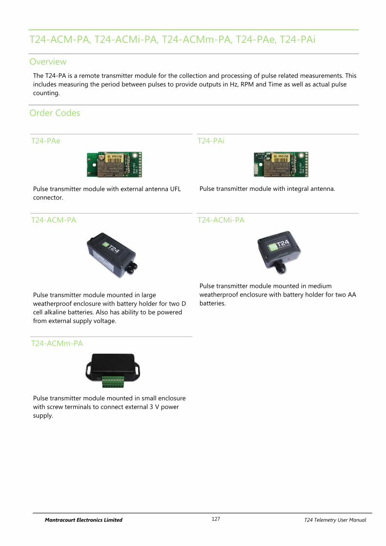
Mantracourt Electronics Limited T24 Telemetry User Manual 127
T24-ACM-PA, T24-ACMi-PA, T24-ACMm-PA, T24-PAe, T24-PAi
Overview
The T24-PA is a remote transmitter module for the collection and processing of pulse related measurements. This
includes measuring the period between pulses to provide outputs in Hz, RPM and Time as well as actual pulse
counting.
Order Codes
T24-PAe
Pulse transmitter module with external antenna UFL
connector.
T24-PAi
Pulse transmitter module with integral antenna.
T24-ACM-PA
Pulse transmitter module mounted in large
weatherproof enclosure with battery holder for two D
cell alkaline batteries. Also has ability to be powered
from external supply voltage.
T24-ACMi-PA
Pulse transmitter module mounted in medium
weatherproof enclosure with battery holder for two AA
batteries.
T24-ACMm-PA
Pulse transmitter module mounted in small enclosure
with screw terminals to connect external 3 V power
supply.
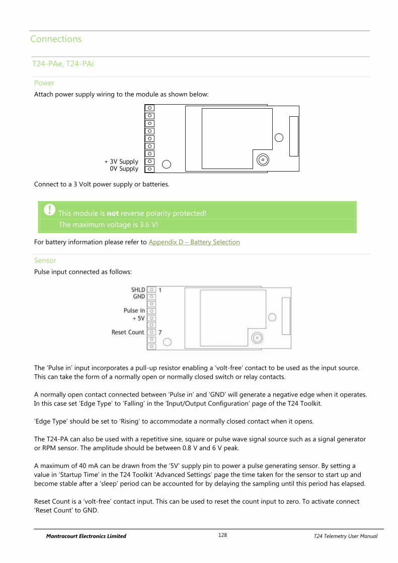
Mantracourt Electronics Limited T24 Telemetry User Manual 128
Connections
T24-PAe, T24-PAi
Power
Attach power supply wiring to the module as shown below:
+ 3V Supply0V Supply
Connect to a 3 Volt power supply or batteries.
This module is not reverse polarity protected!
The maximum voltage is 3.6 V!
For battery information please refer to Appendix D – Battery Selection
Sensor
Pulse input connected as follows:
The ‘Pulse in’ input incorporates a pull-up resistor enabling a ‘volt-free’ contact to be used as the input source.
This can take the form of a normally open or normally closed switch or relay contacts.
A normally open contact connected between ‘Pulse in’ and ‘GND’ will generate a negative edge when it operates.
In this case set ‘Edge Type’ to ‘Falling’ in the ‘Input/Output Configuration’ page of the T24 Toolkit.
‘Edge Type’ should be set to ‘Rising’ to accommodate a normally closed contact when it opens.
The T24-PA can also be used with a repetitive sine, square or pulse wave signal source such as a signal generator
or RPM sensor. The amplitude should be between 0.8 V and 6 V peak.
A maximum of 40 mA can be drawn from the ‘5V’ supply pin to power a pulse generating sensor. By setting a
value in ‘Startup Time’ in the T24 Toolkit ‘Advanced Settings’ page the time taken for the sensor to start up and
become stable after a ‘sleep’ period can be accounted for by delaying the sampling until this period has elapsed.
Reset Count is a ‘volt-free’ contact input. This can be used to reset the count input to zero. To activate connect
‘Reset Count’ to GND.
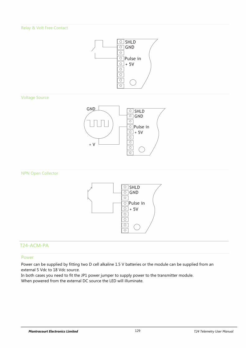
Mantracourt Electronics Limited T24 Telemetry User Manual 129
Relay & Volt Free Contact
+ 5V
SHLDGND
Pulse in
Voltage Source
+ 5V
SHLDGND
Pulse in
+ V
GND
NPN Open Collector
+ 5V
SHLDGND
Pulse in
T24-ACM-PA
Power
Power can be supplied by fitting two D cell alkaline 1.5 V batteries or the module can be supplied from an
external 5 Vdc to 18 Vdc source.
In both cases you need to fit the JP1 power jumper to supply power to the transmitter module.
When powered from the external DC source the LED will illuminate.
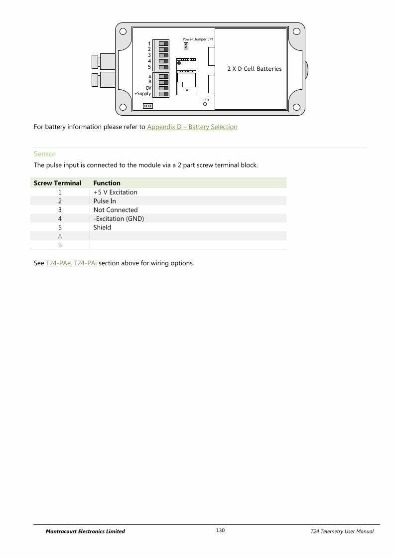
Mantracourt Electronics Limited T24 Telemetry User Manual 130
2 X D Cell Batteries
AB
0V+Supply
12345
Power Jumper JP1
LED
For battery information please refer to Appendix D – Battery Selection
Sensor
The pulse input is connected to the module via a 2 part screw terminal block.
Screw Terminal Function
1 +5 V Excitation
2 Pulse In
3 Not Connected
4 -Excitation (GND)
5 Shield
A
B
See T24-PAe, T24-PAi section above for wiring options.

Mantracourt Electronics Limited T24 Telemetry User Manual 131
T24-ACMi-PA
Power
The enclosure is designed to accept two AA batteries. Maximum voltage 1.8 V per cell.
For battery information please refer to Appendix D – Battery Selection
Sensor
The input connections are accessed by lifting the right hand cover plate, this plate incorporates the T24-ACMi
Antenna; take extra care when re-assembling that the grey UHF cable is attached to the antenna socket.
Screw Terminal Function
1 Shield
2 -Excitation (GND)
3 Not Connected
4 Pulse In
5 + 5 V Excitation
See T24-PAe, T24-PAi section above for wiring options.
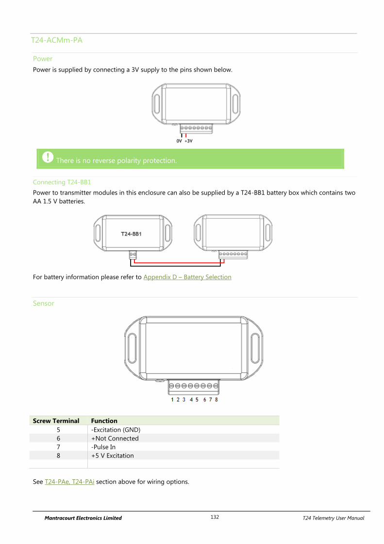
Mantracourt Electronics Limited T24 Telemetry User Manual 132
T24-ACMm-PA
Power
Power is supplied by connecting a 3V supply to the pins shown below.
There is no reverse polarity protection.
Connecting T24-BB1
Power to transmitter modules in this enclosure can also be supplied by a T24-BB1 battery box which contains two
AA 1.5 V batteries.
For battery information please refer to Appendix D – Battery Selection
Sensor
Screw Terminal Function
5 -Excitation (GND)
6 +Not Connected
7 -Pulse In
8 +5 V Excitation
See T24-PAe, T24-PAi section above for wiring options.

Mantracourt Electronics Limited T24 Telemetry User Manual 133
Shield Connections (All Enclosures)
We recommend the following rules to determine whether there should be a connection between the transmitter
module shield and the sensor chassis or cable:
1. If the sensor is remote to the transmitter module and the screen of the signal cable is NOT connected to the
sensor chassis then the cable screen should be connected to the transmitter module shield connection.
2. If the sensor is remote to the transmitter module and the screen of the signal cable IS connected to the sensor
chassis then the cable screen should NOT connected to the transmitter module shield connection.
3. If the transmitter module is integral to the sensor or mounted very close and the module is mounted on a metal
chassis then the answer to whether the transmitter module shield connection should be connected to the metal
chassis is a matter of experimentation. This connection must be as short as possible. The T24 Toolkit can be used
to chart the signal levels and tests should be undertaken to determine whether there is a better radio signal with
or without the shield/chassis connection. The quality of the measured reading should also be looked at. In cases
where the shield/chassis connection makes no difference to the radio signal or the reading quality then the
connection should be made.
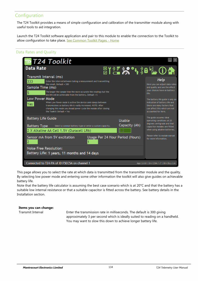
Mantracourt Electronics Limited T24 Telemetry User Manual 134
Configuration
The T24 Toolkit provides a means of simple configuration and calibration of the transmitter module along with
useful tools to aid integration.
Launch the T24 Toolkit software application and pair to this module to enable the connection to the Toolkit to
allow configuration to take place. See Common Toolkit Pages - Home
Data Rates and Quality
This page allows you to select the rate at which data is transmitted from the transmitter module and the quality.
By selecting low power mode and entering some other information the toolkit will also give guides on achievable
battery life.
Note that the battery life calculator is assuming the best case scenario which is at 20°C and that the battery has a
suitable low internal resistance or that a suitable capacitor is fitted across the battery. See battery details in the
Installation section.
Items you can change:
Transmit Interval Enter the transmission rate in milliseconds. The default is 300 giving
approximately 3 per second which is ideally suited to reading on a handheld.
You may want to slow this down to achieve longer battery life.
Mantracourt Electronics Limited T24 Telemetry User Manual 135
Sample Time This is the length of time in milliseconds that the input is sampled before the
value is transmitted. This can vary between 5 milliseconds and close to the
Transmit Interval.
The Sample time should be set to at least twice the
maximum time period that is to be captured to ensure
accurate capture of incoming pulses.
A shorter sample time means that the module is awake for less time so battery
life is increased but at the expense of a reading with less noise free resolution.
You can vary this to see the effect on battery life.
Low Power Mode Unless the transmitter module is non battery powered this should be set to Yes.
In between transmissions the transmitter module will enter sleep mode which,
for some modules such as the strain gauge transmitter module, will have a
massive effect on battery life.
A Reason for not using Low Power Mode would be if using the module in a
Master-Slave arrangement with PC for example.
Battery Type This is not a parameter of the module but information used by the battery life
guide. You can choose from some preset batteries or choose custom to allow
you to select your own battery capacity. See below. This will also offer to change
the Battery Low Level if the level suitable for the chosen battery is not the level
currently set.
Usable Capacity This is not a parameter of the module but information used by the battery life
guide. This is the capacity of the battery in amp hours and has a profound effect
on battery life calculations. This capacity needs to be calculated from battery
manufacturer’s data sheets to take into account that you can only use batteries
down to 2.1 volts so in the case of twin AA cells this would be 1.05 volts.
Generally the usable capacity will not be as high as that advertised by the
battery manufacturer. Temperature and internal resistance of the battery are not
taken into account in the guide.
Sensor mA from 5V Excitation
This is the current drawn by any sensor attached to the 5 V on board power
supply.
Usage Per 24 Hour Period Enter the number of hours per 24 hour period that the module will be turned on
and transmitting.
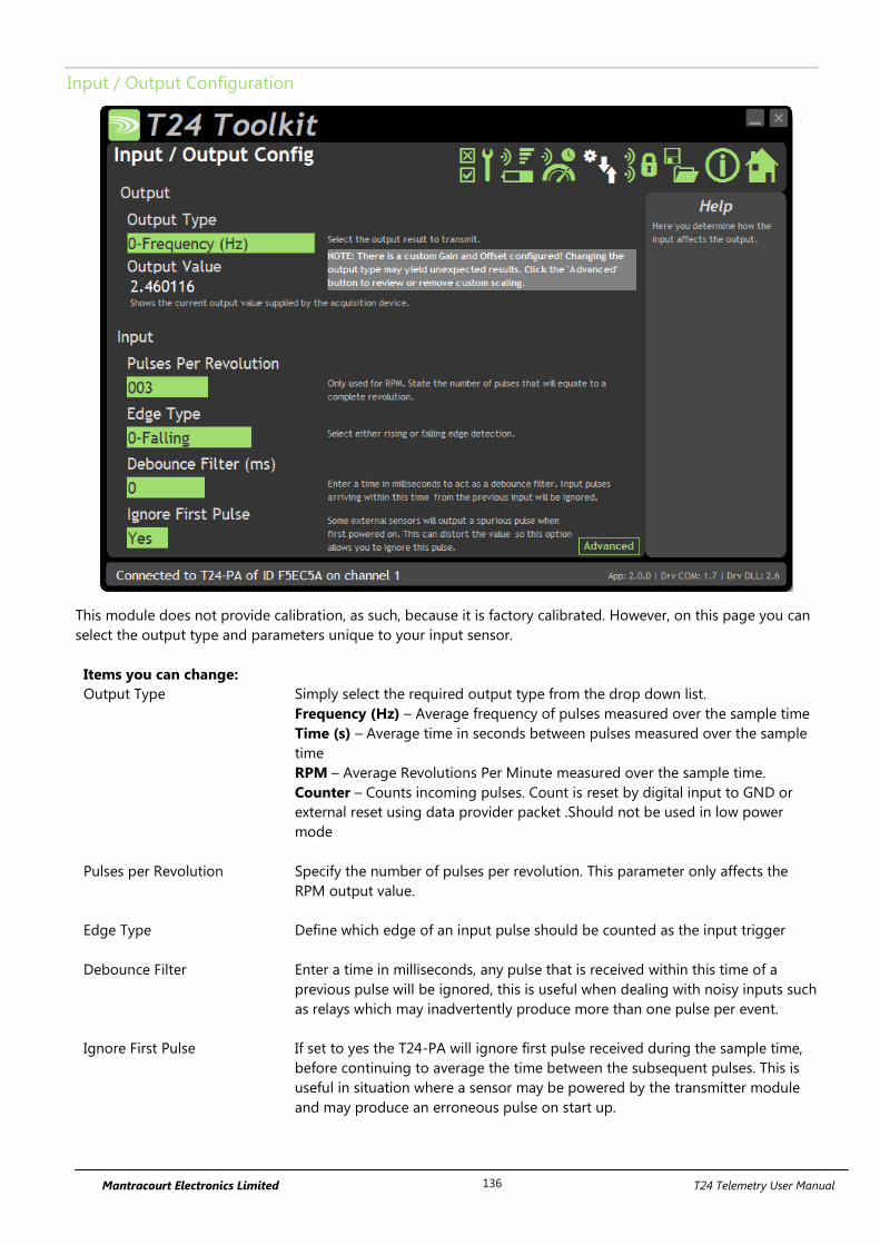
Mantracourt Electronics Limited T24 Telemetry User Manual 136
Input / Output Configuration
This module does not provide calibration, as such, because it is factory calibrated. However, on this page you can
select the output type and parameters unique to your input sensor.
Items you can change:
Output Type Simply select the required output type from the drop down list.
Frequency (Hz) – Average frequency of pulses measured over the sample time
Time (s) – Average time in seconds between pulses measured over the sample
time
RPM – Average Revolutions Per Minute measured over the sample time.
Counter – Counts incoming pulses. Count is reset by digital input to GND or
external reset using data provider packet .Should not be used in low power
mode
Pulses per Revolution Specify the number of pulses per revolution. This parameter only affects the
RPM output value.
Edge Type Define which edge of an input pulse should be counted as the input trigger
Debounce Filter Enter a time in milliseconds, any pulse that is received within this time of a
previous pulse will be ignored, this is useful when dealing with noisy inputs such
as relays which may inadvertently produce more than one pulse per event.
Ignore First Pulse If set to yes the T24-PA will ignore first pulse received during the sample time,
before continuing to average the time between the subsequent pulses. This is
useful in situation where a sensor may be powered by the transmitter module
and may produce an erroneous pulse on start up.
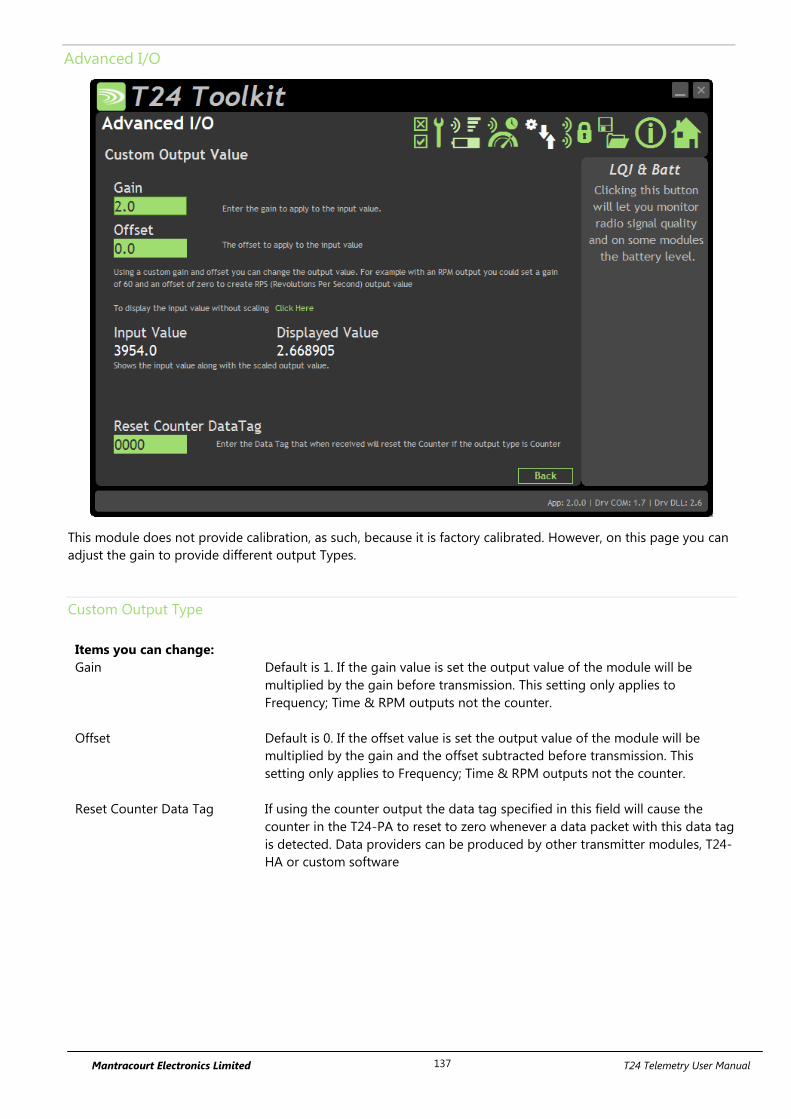
Mantracourt Electronics Limited T24 Telemetry User Manual 137
Advanced I/O
This module does not provide calibration, as such, because it is factory calibrated. However, on this page you can
adjust the gain to provide different output Types.
Custom Output Type
Items you can change:
Gain Default is 1. If the gain value is set the output value of the module will be
multiplied by the gain before transmission. This setting only applies to
Frequency; Time & RPM outputs not the counter.
Offset Default is 0. If the offset value is set the output value of the module will be
multiplied by the gain and the offset subtracted before transmission. This
setting only applies to Frequency; Time & RPM outputs not the counter.
Reset Counter Data Tag If using the counter output the data tag specified in this field will cause the
counter in the T24-PA to reset to zero whenever a data packet with this data tag
is detected. Data providers can be produced by other transmitter modules, T24-
HA or custom software
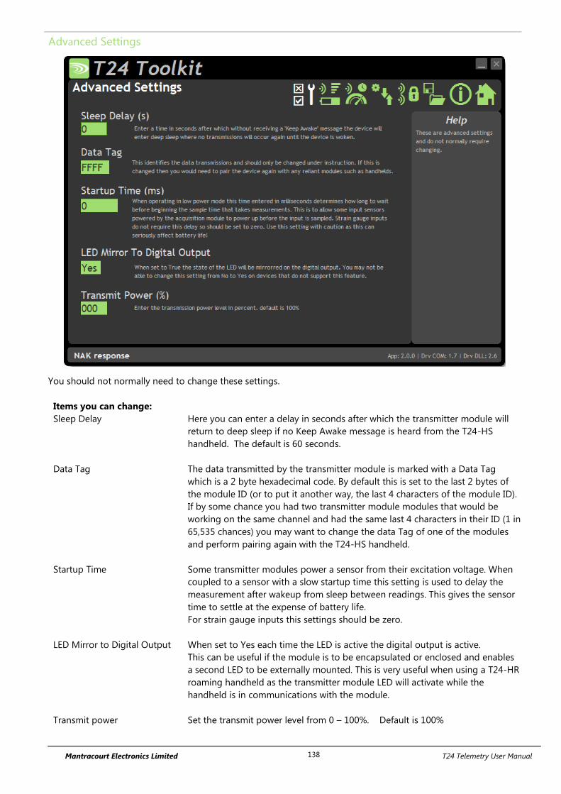
Mantracourt Electronics Limited T24 Telemetry User Manual 138
Advanced Settings
You should not normally need to change these settings.
Items you can change:
Sleep Delay Here you can enter a delay in seconds after which the transmitter module will
return to deep sleep if no Keep Awake message is heard from the T24-HS
handheld. The default is 60 seconds.
Data Tag The data transmitted by the transmitter module is marked with a Data Tag
which is a 2 byte hexadecimal code. By default this is set to the last 2 bytes of
the module ID (or to put it another way, the last 4 characters of the module ID).
If by some chance you had two transmitter module modules that would be
working on the same channel and had the same last 4 characters in their ID (1 in
65,535 chances) you may want to change the data Tag of one of the modules
and perform pairing again with the T24-HS handheld.
Startup Time Some transmitter modules power a sensor from their excitation voltage. When
coupled to a sensor with a slow startup time this setting is used to delay the
measurement after wakeup from sleep between readings. This gives the sensor
time to settle at the expense of battery life.
For strain gauge inputs this settings should be zero.
LED Mirror to Digital Output When set to Yes each time the LED is active the digital output is active.
This can be useful if the module is to be encapsulated or enclosed and enables
a second LED to be externally mounted. This is very useful when using a T24-HR
roaming handheld as the transmitter module LED will activate while the
handheld is in communications with the module.
Transmit power Set the transmit power level from 0 – 100%. Default is 100%
Mantracourt Electronics Limited T24 Telemetry User Manual 139
Enclosure & Mounting
This module is available in a number of different enclosure types. Locate your product and follow the link to view
dimensional and mounting information for that particular enclosure.
T24-PAe, T24-PAi
These OEM modules are bare PCB modules. Please see Appendix A – Enclosures & Mounting – OEM Transmitter
Modules for more information.
T24-ACM-PA
This module is fitted inside our large enclosure. Please see Appendix A – Enclosures & Mounting – ACM for more
information.
T24-ACMi-PA
This module is fitted inside our medium enclosure. Please see Appendix A – Enclosures & Mounting – ACMi for
more information.
T24-ACMm-PA
This module is fitted inside our small enclosure. Please see Appendix A – Enclosures & Mounting – ACMm for
more information.

Mantracourt Electronics Limited T24 Telemetry User Manual 140
Antennas
T24-PAi
This module uses an integrated chip antenna. See Appendix B – Antennas – Internal Chip Antenna
T24-PAe
Only the T24-PAe module allows for the fitting of external antennas. The choices are:
T24-ANTA PCB Antenna See Appendix B – Antennas – T24-ANTA
T24-ANTB Dipole Antenna See Appendix B – Antennas – T24-ANTB
T24-ANTC Dipole Antenna Swivel See Appendix B – Antennas – T24-ANTC
T24-ANTD Puck Antenna SMA See Appendix B – Antennas – T24-ANTD
T24-ANTE Puck Antenna UFL See Appendix B – Antennas – T24-ANTE
T24-ACM-PA, T24-ACMi-PA, T24-ACMm-PA
These modules have the antenna already fitted inside the enclosure so there are no specific mounting
requirements.
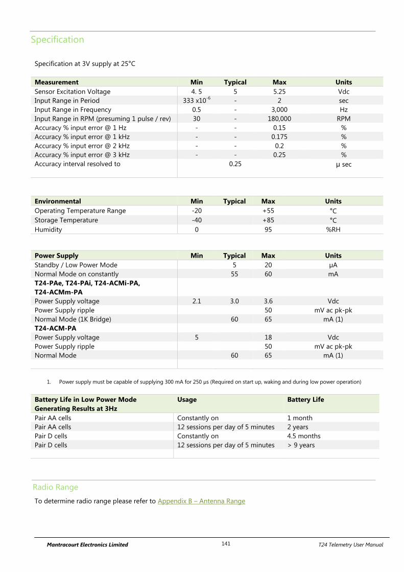
Mantracourt Electronics Limited T24 Telemetry User Manual 141
Specification
Specification at 3V supply at 25°C
Measurement Min Typical Max Units
Sensor Excitation Voltage 4. 5 5 5.25 Vdc
Input Range in Period 333 x10-6
- 2 sec
Input Range in Frequency 0.5 - 3,000 Hz
Input Range in RPM (presuming 1 pulse / rev) 30 - 180,000 RPM
Accuracy % input error @ 1 Hz - - 0.15 %
Accuracy % input error @ 1 kHz - - 0.175 %
Accuracy % input error @ 2 kHz - - 0.2 %
Accuracy % input error @ 3 kHz - - 0.25 %
Accuracy interval resolved to 0.25 µ sec
Environmental Min Typical Max Units
Operating Temperature Range -20 +55 °C
Storage Temperature -40 +85 °C
Humidity 0 95 %RH
Power Supply Min Typical Max Units
Standby / Low Power Mode 5 20 µA
Normal Mode on constantly 55 60 mA
T24-PAe, T24-PAi, T24-ACMi-PA,
T24-ACMm-PA
Power Supply voltage 2.1 3.0 3.6 Vdc
Power Supply ripple 50 mV ac pk-pk
Normal Mode (1K Bridge) 60 65 mA (1)
T24-ACM-PA
Power Supply voltage 5 18 Vdc
Power Supply ripple 50 mV ac pk-pk
Normal Mode 60 65 mA (1)
1. Power supply must be capable of supplying 300 mA for 250 µs (Required on start up, waking and during low power operation)
Battery Life in Low Power Mode
Generating Results at 3Hz
Usage Battery Life
Pair AA cells Constantly on 1 month
Pair AA cells 12 sessions per day of 5 minutes 2 years
Pair D cells Constantly on 4.5 months
Pair D cells 12 sessions per day of 5 minutes > 9 years
Radio Range
To determine radio range please refer to Appendix B – Antenna Range
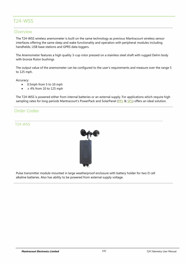
Mantracourt Electronics Limited T24 Telemetry User Manual 142
T24-WSS
Overview
The T24-WSS wireless anemometer is built on the same technology as previous Mantracourt wireless sensor
interfaces offering the same sleep and wake functionality and operation with peripheral modules including
handhelds, USB base stations and GPRS data loggers.
The Anemometer features a high quality 3-cup rotor pressed on a stainless steel shaft with rugged Delrin body
with bronze Rulon bushings
The output value of the anemometer can be configured to the user’s requirements and measure over the range 5
to 125 mph.
Accuracy:
0.5mph from 5 to 10 mph
± 4% from 10 to 125 mph
The T24-WSS is powered either from internal batteries or an external supply. For applications which require high
sampling rates for long periods Mantracourt’s PowerPack and SolarPanel (PP1 & SP1) offers an ideal solution.
Order Codes
T24-WSS
Pulse transmitter module mounted in large weatherproof enclosure with battery holder for two D cell
alkaline batteries. Also has ability to be powered from external supply voltage.
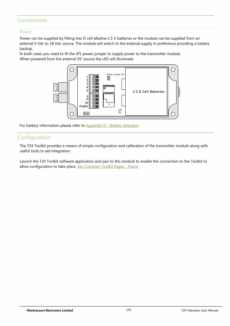
Mantracourt Electronics Limited T24 Telemetry User Manual 143
Connections
Power
Power can be supplied by fitting two D cell alkaline 1.5 V batteries or the module can be supplied from an
external 5 Vdc to 18 Vdc source. The module will switch to the external supply in preference providing a battery
backup.
In both cases you need to fit the JP1 power jumper to supply power to the transmitter module.
When powered from the external DC source the LED will illuminate.
2 X D Cell Batteries
AB
0V+Supply
12345
Power Jumper JP1
LED
For battery information please refer to Appendix D – Battery Selection
Configuration
The T24 Toolkit provides a means of simple configuration and calibration of the transmitter module along with
useful tools to aid integration.
Launch the T24 Toolkit software application and pair to this module to enable the connection to the Toolkit to
allow configuration to take place. See Common Toolkit Pages - Home
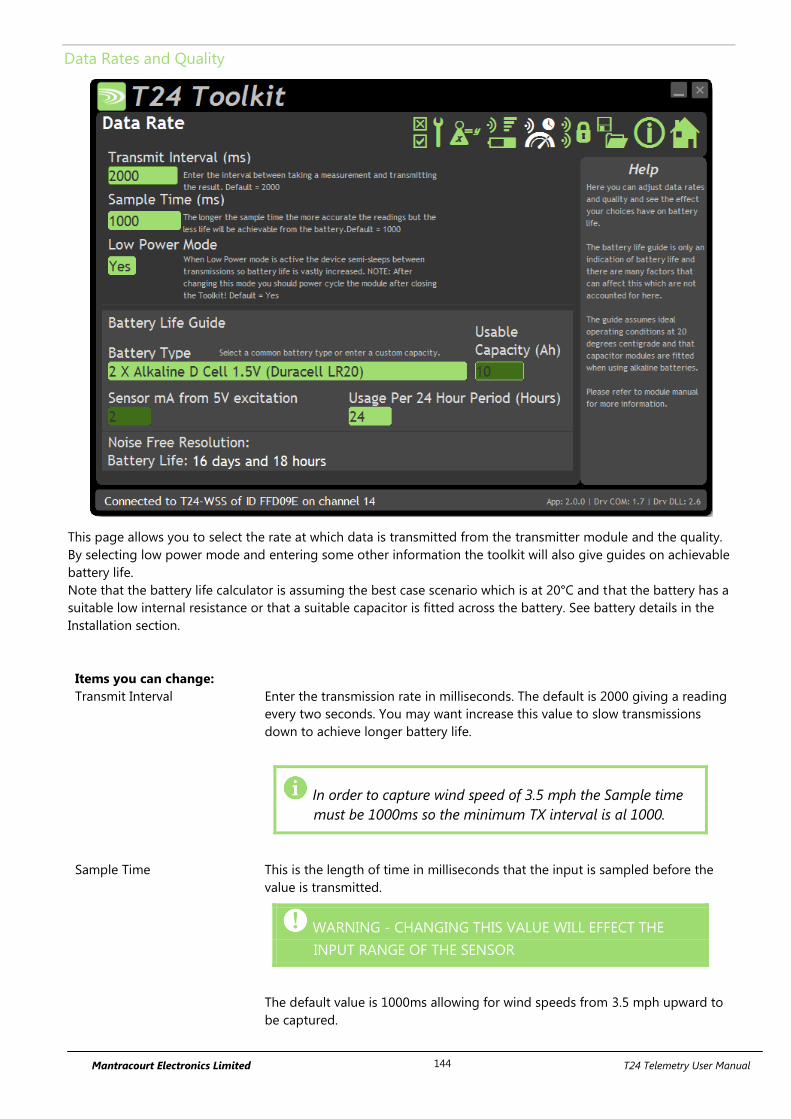
Mantracourt Electronics Limited T24 Telemetry User Manual 144
Data Rates and Quality
This page allows you to select the rate at which data is transmitted from the transmitter module and the quality.
By selecting low power mode and entering some other information the toolkit will also give guides on achievable
battery life.
Note that the battery life calculator is assuming the best case scenario which is at 20°C and that the battery has a
suitable low internal resistance or that a suitable capacitor is fitted across the battery. See battery details in the
Installation section.
Items you can change:
Transmit Interval Enter the transmission rate in milliseconds. The default is 2000 giving a reading
every two seconds. You may want increase this value to slow transmissions
down to achieve longer battery life.
In order to capture wind speed of 3.5 mph the Sample time
must be 1000ms so the minimum TX interval is al 1000.
Sample Time This is the length of time in milliseconds that the input is sampled before the
value is transmitted.
WARNING - CHANGING THIS VALUE WILL EFFECT THE
INPUT RANGE OF THE SENSOR
The default value is 1000ms allowing for wind speeds from 3.5 mph upward to
be captured.
Mantracourt Electronics Limited T24 Telemetry User Manual 145
Low Power Mode Unless the transmitter module is non battery powered this should be set to Yes.
In between transmissions the transmitter module will enter sleep mode which,
for some modules such as the strain gauge transmitter module, will have a
massive effect on battery life.
A Reason for not using Low Power Mode would be if using the module in a
Master-Slave arrangement with PC for example. Or if there is less than 40ms
between the sample time and transmit interval.
Battery Type This is not a parameter of the module but information used by the battery life
guide. You can choose from some preset batteries or choose custom to allow
you to select your own battery capacity. See below. This will also offer to change
the Battery Low Level if the level suitable for the chosen battery is not the level
currently set.
Usable Capacity This is not a parameter of the module but information used by the battery life
guide. This is the capacity of the battery in Amp Hours and has a profound
effect on battery life calculations. This capacity needs to be calculated from
battery manufacturer’s data sheets to take into account that you can only use
batteries down to 2.1 volts so in the case of twin AA cells this would be 1.05
volts.
Generally the usable capacity will not be as high as that advertised by the
battery manufacturer. Temperature and internal resistance of the battery are not
taken into account in the guide.
Sensor mA from 5V Excitation
This is the current drawn by the sensor; this should be set to 2 mA for the T24-
WSS to provide a conservative battery life guide.
Usage Per 24 Hour Period Enter the number of hours per 24 hour period that the module will be turned on
and transmitting.
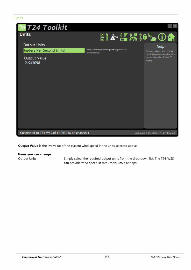
Mantracourt Electronics Limited T24 Telemetry User Manual 146
Units
Output Value is the live value of the current wind speed in the units selected above.
Items you can change:
Output Units Simply select the required output units from the drop down list. The T24-WSS
can provide wind speed in m/s , mph, km/h and fps
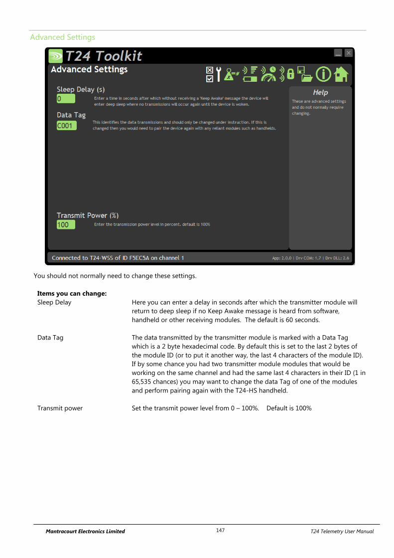
Mantracourt Electronics Limited T24 Telemetry User Manual 147
Advanced Settings
You should not normally need to change these settings.
Items you can change:
Sleep Delay Here you can enter a delay in seconds after which the transmitter module will
return to deep sleep if no Keep Awake message is heard from software,
handheld or other receiving modules. The default is 60 seconds.
Data Tag The data transmitted by the transmitter module is marked with a Data Tag
which is a 2 byte hexadecimal code. By default this is set to the last 2 bytes of
the module ID (or to put it another way, the last 4 characters of the module ID).
If by some chance you had two transmitter module modules that would be
working on the same channel and had the same last 4 characters in their ID (1 in
65,535 chances) you may want to change the data Tag of one of the modules
and perform pairing again with the T24-HS handheld.
Transmit power Set the transmit power level from 0 – 100%. Default is 100%
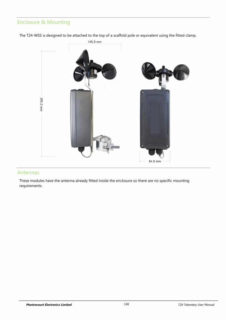
Mantracourt Electronics Limited T24 Telemetry User Manual 148
Enclosure & Mounting
The T24-WSS is designed to be attached to the top of a scaffold pole or equivalent using the fitted clamp.
Antennas
These modules have the antenna already fitted inside the enclosure so there are no specific mounting
requirements.
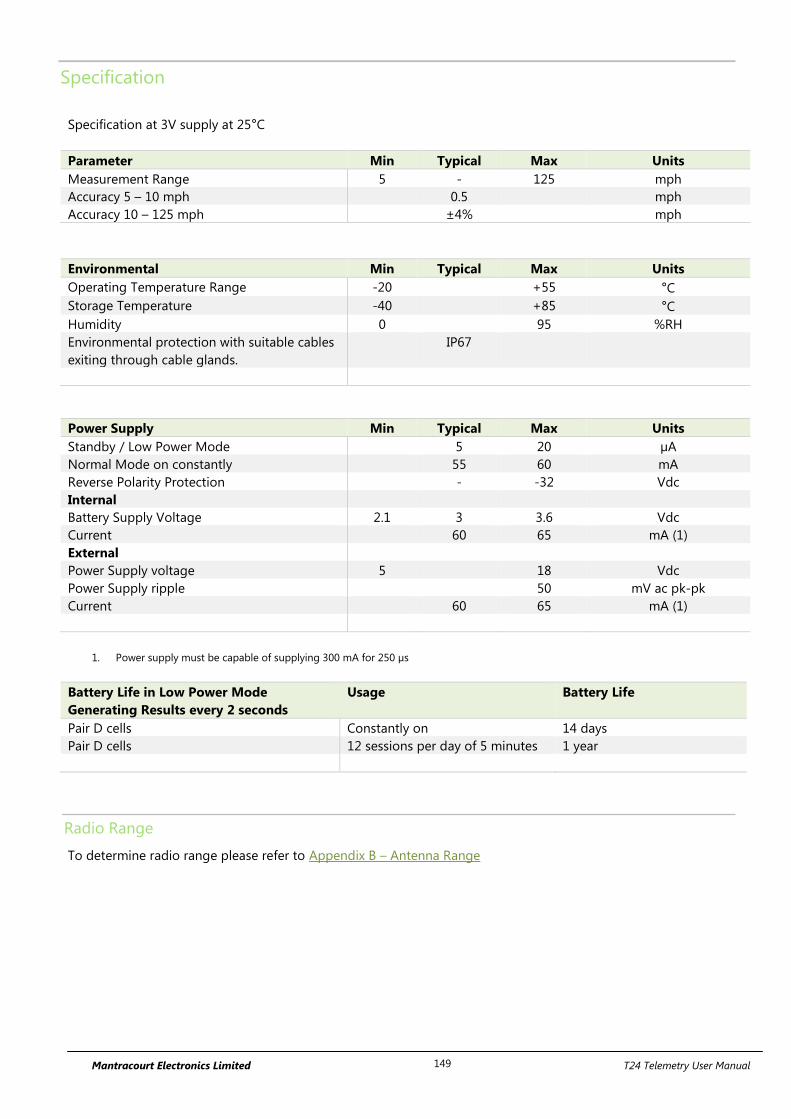
Mantracourt Electronics Limited T24 Telemetry User Manual 149
Specification
Specification at 3V supply at 25°C
Parameter Min Typical Max Units
Measurement Range 5 - 125 mph
Accuracy 5 – 10 mph 0.5 mph
Accuracy 10 – 125 mph ±4% mph
Environmental Min Typical Max Units
Operating Temperature Range -20 +55 °C
Storage Temperature -40 +85 °C
Humidity 0 95 %RH
Environmental protection with suitable cables
exiting through cable glands.
IP67
Power Supply Min Typical Max Units
Standby / Low Power Mode 5 20 µA
Normal Mode on constantly 55 60 mA
Reverse Polarity Protection - -32 Vdc
Internal
Battery Supply Voltage 2.1 3 3.6 Vdc
Current 60 65 mA (1)
External
Power Supply voltage 5 18 Vdc
Power Supply ripple 50 mV ac pk-pk
Current 60 65 mA (1)
1. Power supply must be capable of supplying 300 mA for 250 µs
Battery Life in Low Power Mode
Generating Results every 2 seconds
Usage Battery Life
Pair D cells Constantly on 14 days
Pair D cells 12 sessions per day of 5 minutes 1 year
Radio Range
To determine radio range please refer to Appendix B – Antenna Range
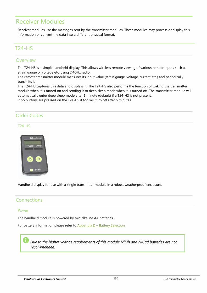
Mantracourt Electronics Limited T24 Telemetry User Manual 150
Receiver Modules
Receiver modules use the messages sent by the transmitter modules. These modules may process or display this
information or convert the data into a different physical format.
T24-HS
Overview
The T24-HS is a simple handheld display. This allows wireless remote viewing of various remote inputs such as
strain gauge or voltage etc. using 2.4GHz radio.
The remote transmitter module measures its input value (strain gauge, voltage, current etc.) and periodically
transmits it.
The T24-HS captures this data and displays it. The T24-HS also performs the function of waking the transmitter
module when it is turned on and sending it to deep sleep mode when it is turned off. The transmitter module will
automatically enter deep sleep mode after 1 minute (default) if a T24-HS is not present.
If no buttons are pressed on the T24-HS it too will turn off after 5 minutes.
Order Codes
T24-HS
Handheld display for use with a single transmitter module in a robust weatherproof enclosure.
Connections
Power
The handheld module is powered by two alkaline AA batteries.
For battery information please refer to Appendix D – Battery Selection
Due to the higher voltage requirements of this module NiMh and NiCad batteries are not
recommended.
Mantracourt Electronics Limited T24 Telemetry User Manual 151
Quick Start
This section will show you how to get the module pair working out of the box.
You will require two AA alkaline batteries for the handheld and a 3 Volt dc supply for the transmitter module
which may also be a pair of AA batteries.
Connecting Power
T24-HS
Remove the two screws on the rear battery compartment. Insert two alkaline AA batteries. Refit the battery
compartment cover. The handheld module is now switched on so should be turned off until the transmitter
module is ready. To turn off just hold down the power key until the display shows BUSY then release it.
Transmitter Module
See the relevant transmitter module manual section for information about connecting power.
Pairing
You will use automatic pairing to prove the connectivity and operation. Pairing sets the communications
configuration parameters to allow the two modules to communicate. You do not need a PC or laptop or any
configuration software to perform basic pairing.
Ensure that transmitter module is not powered.
You need to turn on the T24-HS in pairing mode. To do this you start with it turned off. Whilst pressing
the power key press the tare key as well until 'PAIRING' is seen on the display. The keys can now be
released.
Now apply power to the transmitter module within 10 seconds.
If successful the T24-HS will pair to the transmitter module and the display will show a numeric value. (Or
Error 2 if the input integrity has failed. For example if the transmitter module is a T24-SA and the strain
gauge is not connected).
If the display shows Failed or -------- then the pairing failed. Try again.
Once successful the T24-HS will be linked to the transmitter module and will send it to sleep when the handheld
is turned off and wake it when the handheld is turned on.
Remember that from this point onwards to turn the handheld on you just need to press and hold the power key
as the pairing function is no longer required. Pairing was just used as a method of setting the transmitter module
to the radio settings already configured in the handheld.
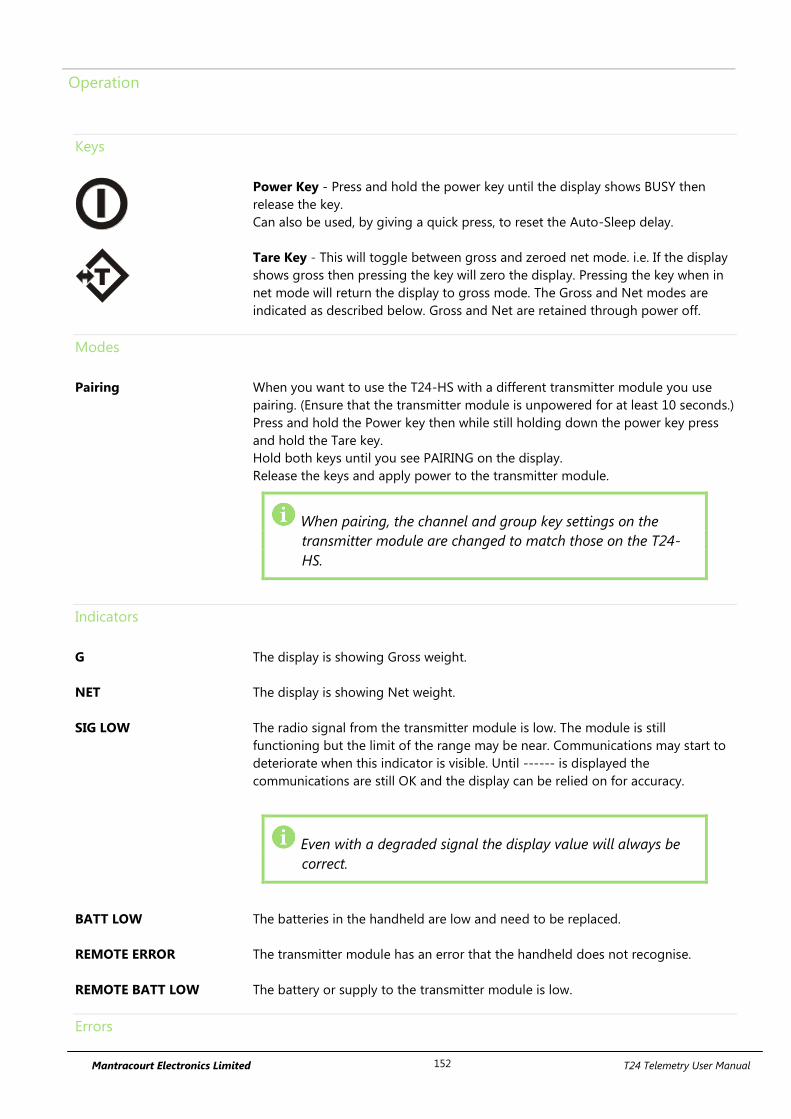
Mantracourt Electronics Limited T24 Telemetry User Manual 152
Operation
Keys
Power Key - Press and hold the power key until the display shows BUSY then
release the key.
Can also be used, by giving a quick press, to reset the Auto-Sleep delay.
T
Tare Key - This will toggle between gross and zeroed net mode. i.e. If the display
shows gross then pressing the key will zero the display. Pressing the key when in
net mode will return the display to gross mode. The Gross and Net modes are
indicated as described below. Gross and Net are retained through power off.
Modes
Pairing When you want to use the T24-HS with a different transmitter module you use
pairing. (Ensure that the transmitter module is unpowered for at least 10 seconds.)
Press and hold the Power key then while still holding down the power key press
and hold the Tare key.
Hold both keys until you see PAIRING on the display.
Release the keys and apply power to the transmitter module.
When pairing, the channel and group key settings on the
transmitter module are changed to match those on the T24-
HS.
Indicators
G The display is showing Gross weight.
NET The display is showing Net weight.
SIG LOW The radio signal from the transmitter module is low. The module is still
functioning but the limit of the range may be near. Communications may start to
deteriorate when this indicator is visible. Until ------ is displayed the
communications are still OK and the display can be relied on for accuracy.
Even with a degraded signal the display value will always be
correct.
BATT LOW The batteries in the handheld are low and need to be replaced.
REMOTE ERROR The transmitter module has an error that the handheld does not recognise.
REMOTE BATT LOW The battery or supply to the transmitter module is low.
Errors

Mantracourt Electronics Limited T24 Telemetry User Manual 153
Displayed on handheld LCD.
Error 1 The transmitter module has a strain gauge input and is in shunt calibration mode.
An external module has placed the transmitter module in Shunt Calibration mode
so rather than display a misleading reading this error is displayed instead.
Modules such as the T24-SA support this error type.
Error 2 Input integrity error. The transmitter module has found a problem with the input.
There may be open or short circuits. Rather than display a misleading reading this
error is displayed instead.
Only certain transmitter modules support this error such as the T24-SA.
Overload The overload limit set by the user has been exceeded.

Mantracourt Electronics Limited T24 Telemetry User Manual 154
Configuration
The T24 Toolkit provides a means of simple configuration of the handheld module along with useful tools to aid
integration.
Launch the T24 Toolkit software application and pair to this module to enable the connection to the Toolkit to
allow configuration to take place. See Common Toolkit Pages - Home
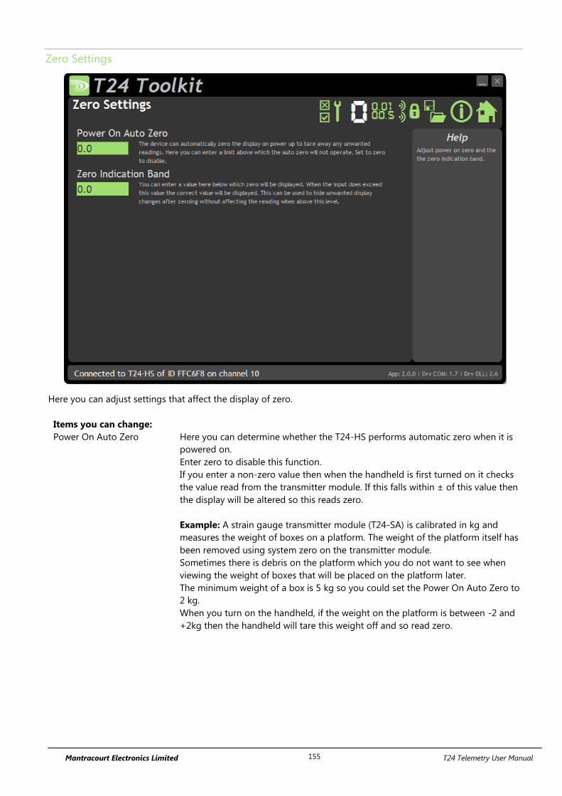
Mantracourt Electronics Limited T24 Telemetry User Manual 155
Zero Settings
Here you can adjust settings that affect the display of zero.
Items you can change:
Power On Auto Zero Here you can determine whether the T24-HS performs automatic zero when it is
powered on.
Enter zero to disable this function.
If you enter a non-zero value then when the handheld is first turned on it checks
the value read from the transmitter module. If this falls within ± of this value then
the display will be altered so this reads zero.
Example: A strain gauge transmitter module (T24-SA) is calibrated in kg and
measures the weight of boxes on a platform. The weight of the platform itself has
been removed using system zero on the transmitter module.
Sometimes there is debris on the platform which you do not want to see when
viewing the weight of boxes that will be placed on the platform later.
The minimum weight of a box is 5 kg so you could set the Power On Auto Zero to
2 kg.
When you turn on the handheld, if the weight on the platform is between -2 and
+2kg then the handheld will tare this weight off and so read zero.

Mantracourt Electronics Limited T24 Telemetry User Manual 156
Zero Indication Band Using this setting you can mask tiny changes in input after you press the Tare
button.
Entering zero will disable this function.
Entering a non-zero value will provide a band within which the display will always
read zero.
Once the reading exceeds this value the real weight will be displayed as no taring
is taking place.
Example: You are adding boxes to a platform and you press tare between adding
each one so you can see the weight of each box.
Without this setting activated each time you tare the display will be around zero
but not exactly zero (By setting the display resolution you may hide this
difference) by setting a small value here such as 0.2kg the display will show a
stable zero while actual weight is fluctuating less than ± 0.2kg.
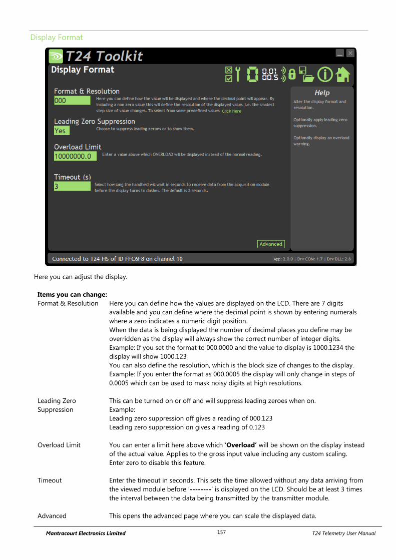
Mantracourt Electronics Limited T24 Telemetry User Manual 157
Display Format
Here you can adjust the display.
Items you can change:
Format & Resolution Here you can define how the values are displayed on the LCD. There are 7 digits
available and you can define where the decimal point is shown by entering numerals
where a zero indicates a numeric digit position.
When the data is being displayed the number of decimal places you define may be
overridden as the display will always show the correct number of integer digits.
Example: If you set the format to 000.0000 and the value to display is 1000.1234 the
display will show 1000.123
You can also define the resolution, which is the block size of changes to the display.
Example: If you enter the format as 000.0005 the display will only change in steps of
0.0005 which can be used to mask noisy digits at high resolutions.
Leading Zero
Suppression
This can be turned on or off and will suppress leading zeroes when on.
Example:
Leading zero suppression off gives a reading of 000.123
Leading zero suppression on gives a reading of 0.123
Overload Limit You can enter a limit here above which ‘Overload’ will be shown on the display instead
of the actual value. Applies to the gross input value including any custom scaling.
Enter zero to disable this feature.
Timeout Enter the timeout in seconds. This sets the time allowed without any data arriving from
the viewed module before ‘--------‘ is displayed on the LCD. Should be at least 3 times
the interval between the data being transmitted by the transmitter module.
Advanced This opens the advanced page where you can scale the displayed data.
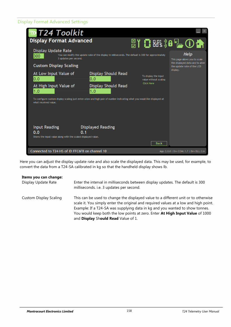
Mantracourt Electronics Limited T24 Telemetry User Manual 158
Display Format Advanced Settings
Here you can adjust the display update rate and also scale the displayed data. This may be used, for example, to
convert the data from a T24-SA calibrated in kg so that the handheld display shows lb.
Items you can change:
Display Update Rate Enter the interval in milliseconds between display updates. The default is 300
milliseconds. i.e. 3 updates per second.
Custom Display Scaling This can be used to change the displayed value to a different unit or to otherwise
scale it. You simply enter the original and required values at a low and high point.
Example: If a T24-SA was supplying data in kg and you wanted to show tonnes.
You would keep both the low points at zero. Enter At High Input Value of 1000
and Display Should Read Value of 1.
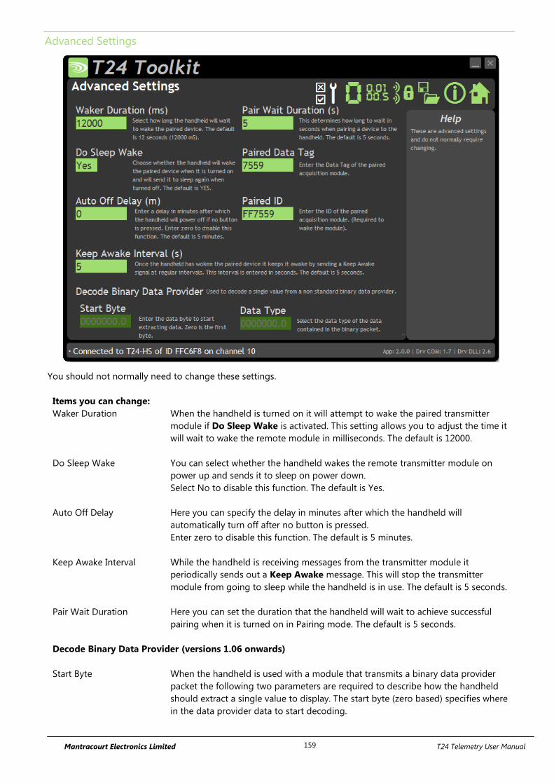
Mantracourt Electronics Limited T24 Telemetry User Manual 159
Advanced Settings
You should not normally need to change these settings.
Items you can change:
Waker Duration When the handheld is turned on it will attempt to wake the paired transmitter
module if Do Sleep Wake is activated. This setting allows you to adjust the time it
will wait to wake the remote module in milliseconds. The default is 12000.
Do Sleep Wake You can select whether the handheld wakes the remote transmitter module on
power up and sends it to sleep on power down.
Select No to disable this function. The default is Yes.
Auto Off Delay Here you can specify the delay in minutes after which the handheld will
automatically turn off after no button is pressed.
Enter zero to disable this function. The default is 5 minutes.
Keep Awake Interval While the handheld is receiving messages from the transmitter module it
periodically sends out a Keep Awake message. This will stop the transmitter
module from going to sleep while the handheld is in use. The default is 5 seconds.
Pair Wait Duration Here you can set the duration that the handheld will wait to achieve successful
pairing when it is turned on in Pairing mode. The default is 5 seconds.
Decode Binary Data Provider (versions 1.06 onwards)
Start Byte When the handheld is used with a module that transmits a binary data provider
packet the following two parameters are required to describe how the handheld
should extract a single value to display. The start byte (zero based) specifies where
in the data provider data to start decoding.

Mantracourt Electronics Limited T24 Telemetry User Manual 160
Data Type Specify the data type to extract. The choices are UINT8, UINT16, INT32 or FLOAT.
You would need to refer to the programmers manual of the appropriate transmitter
module to work out where to extract data from and what type. The default of INT32
with a Start Byte of zero is the default which will be correct for a T24-SAF module.

Mantracourt Electronics Limited T24 Telemetry User Manual 161
Enclosure & Mounting
See Appendix A – Handheld Style section for more information.
Antennas
These modules have the antenna already fitted inside the enclosure so there are no specific mounting
requirements.

Mantracourt Electronics Limited T24 Telemetry User Manual 162
Specification
Electrical Min Typical Max Units
Power Supply voltage 2.5 3.0 3.6 Vdc
Power Supply Min Typical Max Units
Active 35 40 mA
Low power mode 120 160 µA
Estimated Battery life using 2Ahr batteries:
Standby mode (Powered off) 1.5 Years
Continuous operation 35 Hours
Environmental Min Typical Max Units
IP rating IP67
Operating Temperature Range -10 +50 C
Storage Temperature -40 +85 C
Humidity 0 95 %RH
Physical
Hand Held Dimensions 90 mm x 152 mm x 34 mm
Radio Range
To determine radio range please refer to Appendix B – Antenna Range
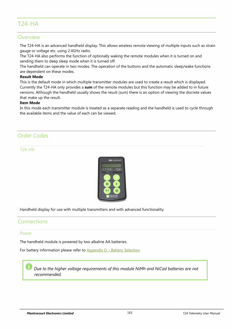
Mantracourt Electronics Limited T24 Telemetry User Manual 163
T24-HA
Overview
The T24-HA is an advanced handheld display. This allows wireless remote viewing of multiple inputs such as strain
gauge or voltage etc. using 2.4GHz radio.
The T24-HA also performs the function of optionally waking the remote modules when it is turned on and
sending them to deep sleep mode when it is turned off.
The handheld can operate in two modes. The operation of the buttons and the automatic sleep/wake functions
are dependent on these modes.
Result Mode
This is the default mode in which multiple transmitter modules are used to create a result which is displayed.
Currently the T24-HA only provides a sum of the remote modules but this function may be added to in future
versions. Although the handheld usually shows the result (sum) there is an option of viewing the discrete values
that make up the result.
Item Mode
In this mode each transmitter module is treated as a separate reading and the handheld is used to cycle through
the available items and the value of each can be viewed.
Order Codes
T24-HA
Handheld display for use with multiple transmitters and with advanced functionality.
Connections
Power
The handheld module is powered by two alkaline AA batteries.
For battery information please refer to Appendix D – Battery Selection
Due to the higher voltage requirements of this module NiMh and NiCad batteries are not
recommended.
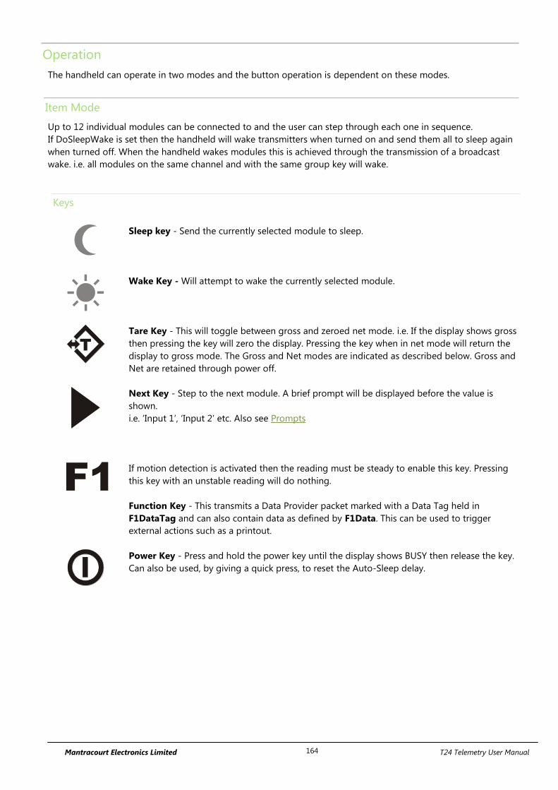
Mantracourt Electronics Limited T24 Telemetry User Manual 164
Operation
The handheld can operate in two modes and the button operation is dependent on these modes.
Item Mode
Up to 12 individual modules can be connected to and the user can step through each one in sequence.
If DoSleepWake is set then the handheld will wake transmitters when turned on and send them all to sleep again
when turned off. When the handheld wakes modules this is achieved through the transmission of a broadcast
wake. i.e. all modules on the same channel and with the same group key will wake.
Keys
Sleep key - Send the currently selected module to sleep.
Wake Key - Will attempt to wake the currently selected module.
T
Tare Key - This will toggle between gross and zeroed net mode. i.e. If the display shows gross
then pressing the key will zero the display. Pressing the key when in net mode will return the
display to gross mode. The Gross and Net modes are indicated as described below. Gross and
Net are retained through power off.
Next Key - Step to the next module. A brief prompt will be displayed before the value is
shown.
i.e. ‘Input 1’, ‘Input 2’ etc. Also see Prompts
F1
If motion detection is activated then the reading must be steady to enable this key. Pressing
this key with an unstable reading will do nothing.
Function Key - This transmits a Data Provider packet marked with a Data Tag held in
F1DataTag and can also contain data as defined by F1Data. This can be used to trigger
external actions such as a printout.
Power Key - Press and hold the power key until the display shows BUSY then release the key.
Can also be used, by giving a quick press, to reset the Auto-Sleep delay.
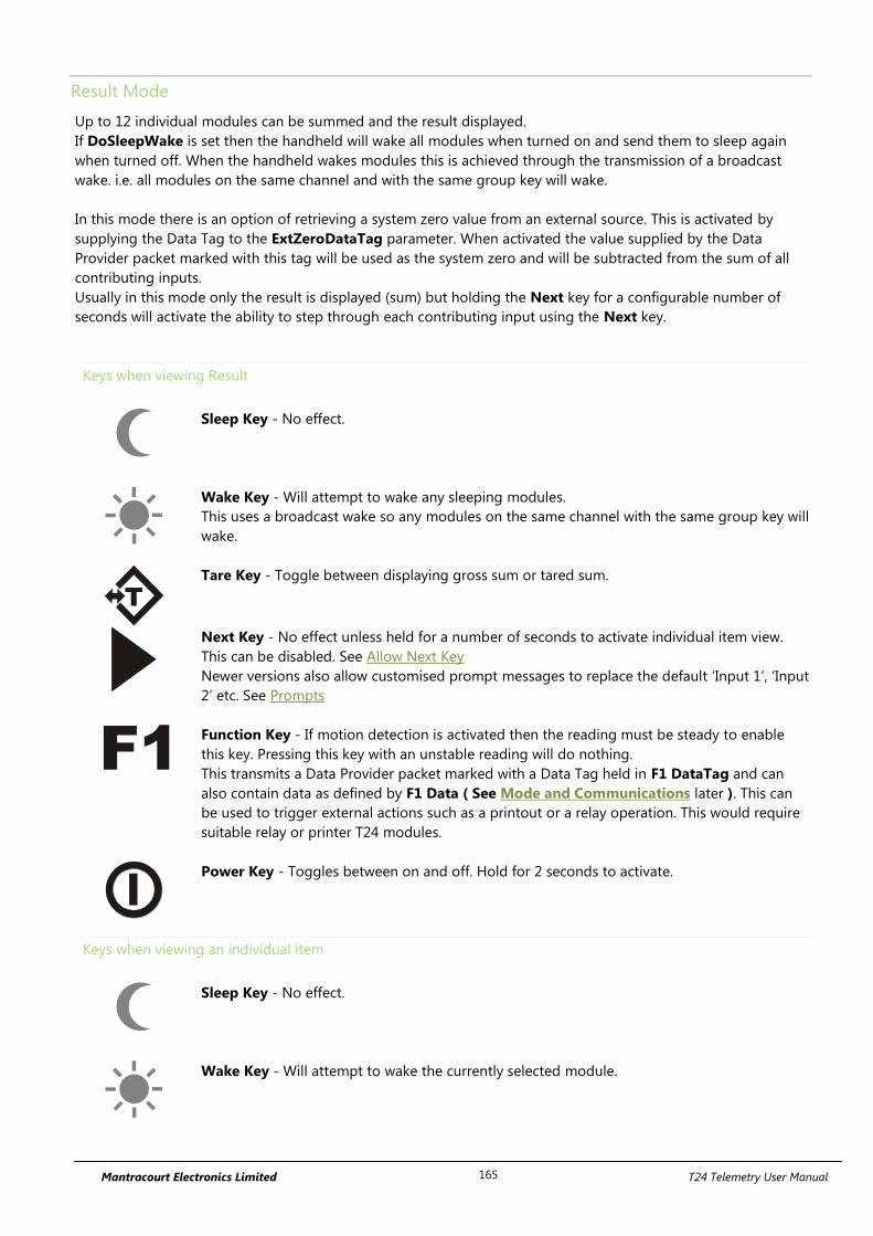
Mantracourt Electronics Limited T24 Telemetry User Manual 165
Result Mode
Up to 12 individual modules can be summed and the result displayed.
If DoSleepWake is set then the handheld will wake all modules when turned on and send them to sleep again
when turned off. When the handheld wakes modules this is achieved through the transmission of a broadcast
wake. i.e. all modules on the same channel and with the same group key will wake.
In this mode there is an option of retrieving a system zero value from an external source. This is activated by
supplying the Data Tag to the ExtZeroDataTag parameter. When activated the value supplied by the Data
Provider packet marked with this tag will be used as the system zero and will be subtracted from the sum of all
contributing inputs.
Usually in this mode only the result is displayed (sum) but holding the Next key for a configurable number of
seconds will activate the ability to step through each contributing input using the Next key.
Keys when viewing Result
Sleep Key - No effect.
Wake Key - Will attempt to wake any sleeping modules.
This uses a broadcast wake so any modules on the same channel with the same group key will
wake.
T
Tare Key - Toggle between displaying gross sum or tared sum.
Next Key - No effect unless held for a number of seconds to activate individual item view.
This can be disabled. See Allow Next Key
Newer versions also allow customised prompt messages to replace the default ‘Input 1’, ‘Input
2’ etc. See Prompts
F1
Function Key - If motion detection is activated then the reading must be steady to enable
this key. Pressing this key with an unstable reading will do nothing.
This transmits a Data Provider packet marked with a Data Tag held in F1 DataTag and can
also contain data as defined by F1 Data ( See Mode and Communications later ). This can
be used to trigger external actions such as a printout or a relay operation. This would require
suitable relay or printer T24 modules.
Power Key - Toggles between on and off. Hold for 2 seconds to activate.
Keys when viewing an individual item
Sleep Key - No effect.
Wake Key - Will attempt to wake the currently selected module.
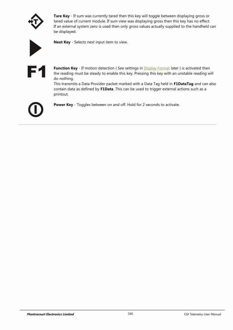
Mantracourt Electronics Limited T24 Telemetry User Manual 166
T
Tare Key - If sum was currently tared then this key will toggle between displaying gross or
tared value of current module. If sum view was displaying gross then this key has no effect.
If an external system zero is used then only gross values actually supplied to the handheld can
be displayed.
Next Key - Selects next input item to view.
F1
Function Key - If motion detection ( See settings in Display Format later ) is activated then
the reading must be steady to enable this key. Pressing this key with an unstable reading will
do nothing.
This transmits a Data Provider packet marked with a Data Tag held in F1DataTag and can also
contain data as defined by F1Data. This can be used to trigger external actions such as a
printout.
Power Key - Toggles between on and off. Hold for 2 seconds to activate.
Mantracourt Electronics Limited T24 Telemetry User Manual 167
All Modes
Indicators
G The display is showing Gross weight.
NET The display is showing Net weight.
SIG LOW The radio signal from the transmitter module is low. The module is still
functioning but the limit of the range may be near. Communications may start
to deteriorate when this indicator is visible. Until ------ is displayed the
communications is still OK and the display can be relied on for accuracy.
Even with a degraded signal the display value will always be
correct.
BATT LOW The batteries in the handheld are low and need to be replaced.
REMOTE ERROR The transmitter module has an error that the handheld does not recognise.
REMOTE BATT LOW The battery or supply to the transmitter module is low.
Errors
Displayed on handheld LCD.
Error 1 The transmitter module has a strain gauge input and is in shunt calibration
mode. An external module has placed the transmitter module in Shunt
Calibration mode so rather than display a misleading reading this error is
displayed instead.
Modules such as the T24-SA support this error type.
Error 2 Input integrity error. The transmitter module has found a problem with the
input. There may be open or short circuits. Rather than display a misleading
reading this error is displayed instead.
Only certain transmitter modules support this error such as the T24-SA.
Overload The overload limit set by the user has been exceeded.
{Display Flashing} The motion detection has been enabled and the reading is deemed in motion
or unstable.
Other Functions
System Zero If enabled, holding the Tare key for a number of seconds will perform a system
zero.
Pairing See Field Transmitter Module Replacement later
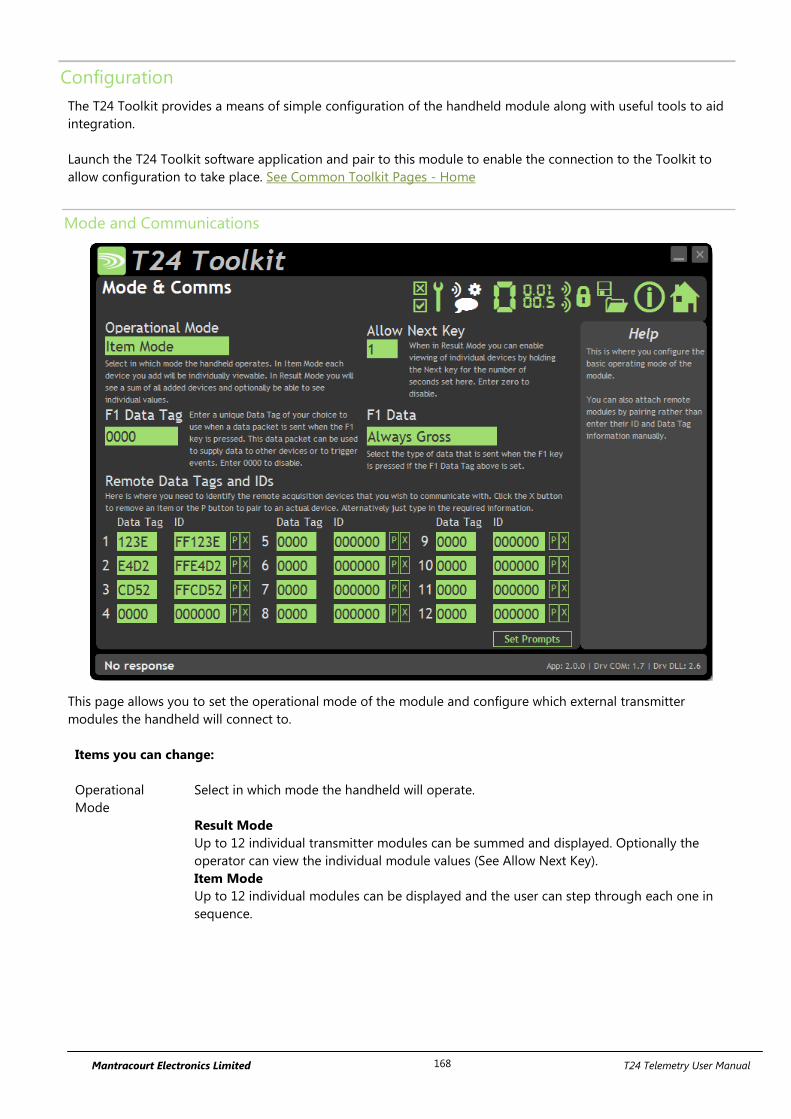
Mantracourt Electronics Limited T24 Telemetry User Manual 168
Configuration
The T24 Toolkit provides a means of simple configuration of the handheld module along with useful tools to aid
integration.
Launch the T24 Toolkit software application and pair to this module to enable the connection to the Toolkit to
allow configuration to take place. See Common Toolkit Pages - Home
Mode and Communications
This page allows you to set the operational mode of the module and configure which external transmitter
modules the handheld will connect to.
Items you can change:
Operational
Mode
Select in which mode the handheld will operate.
Result Mode
Up to 12 individual transmitter modules can be summed and displayed. Optionally the
operator can view the individual module values (See Allow Next Key).
Item Mode
Up to 12 individual modules can be displayed and the user can step through each one in
sequence.
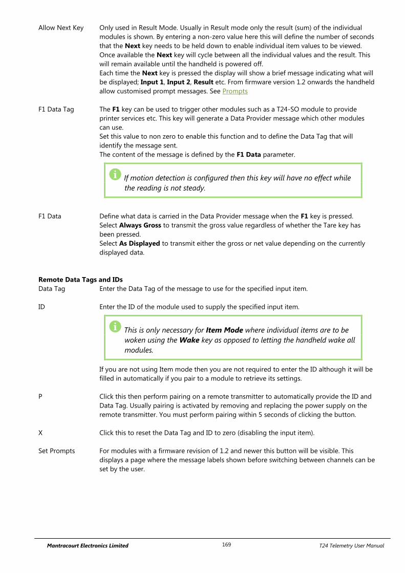
Mantracourt Electronics Limited T24 Telemetry User Manual 169
Allow Next Key Only used in Result Mode. Usually in Result mode only the result (sum) of the individual
modules is shown. By entering a non-zero value here this will define the number of seconds
that the Next key needs to be held down to enable individual item values to be viewed.
Once available the Next key will cycle between all the individual values and the result. This
will remain available until the handheld is powered off.
Each time the Next key is pressed the display will show a brief message indicating what will
be displayed; Input 1, Input 2, Result etc. From firmware version 1.2 onwards the handheld
allow customised prompt messages. See Prompts
F1 Data Tag The F1 key can be used to trigger other modules such as a T24-SO module to provide
printer services etc. This key will generate a Data Provider message which other modules
can use.
Set this value to non zero to enable this function and to define the Data Tag that will
identify the message sent.
The content of the message is defined by the F1 Data parameter.
If motion detection is configured then this key will have no effect while
the reading is not steady.
F1 Data Define what data is carried in the Data Provider message when the F1 key is pressed.
Select Always Gross to transmit the gross value regardless of whether the Tare key has
been pressed.
Select As Displayed to transmit either the gross or net value depending on the currently
displayed data.
Remote Data Tags and IDs
Data Tag Enter the Data Tag of the message to use for the specified input item.
ID Enter the ID of the module used to supply the specified input item.
This is only necessary for Item Mode where individual items are to be
woken using the Wake key as opposed to letting the handheld wake all
modules.
If you are not using Item mode then you are not required to enter the ID although it will be
filled in automatically if you pair to a module to retrieve its settings.
P Click this then perform pairing on a remote transmitter to automatically provide the ID and
Data Tag. Usually pairing is activated by removing and replacing the power supply on the
remote transmitter. You must perform pairing within 5 seconds of clicking the button.
X Click this to reset the Data Tag and ID to zero (disabling the input item).
Set Prompts For modules with a firmware revision of 1.2 and newer this button will be visible. This
displays a page where the message labels shown before switching between channels can be
set by the user.
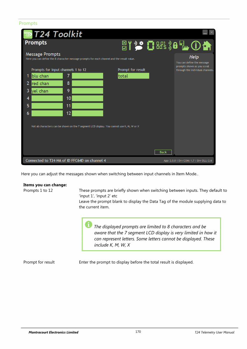
Mantracourt Electronics Limited T24 Telemetry User Manual 170
Prompts
Here you can adjust the messages shown when switching between input channels in Item Mode..
Items you can change:
Prompts 1 to 12 These prompts are briefly shown when switching between inputs. They default to
‘input 1’, ‘input 2’ etc
Leave the prompt blank to display the Data Tag of the module supplying data to
the current item.
The displayed prompts are limited to 8 characters and be
aware that the 7 segment LCD display is very limited in how it
can represent letters. Some letters cannot be displayed. These
include K, M, W, X
Prompt for result Enter the prompt to display before the total result is displayed.
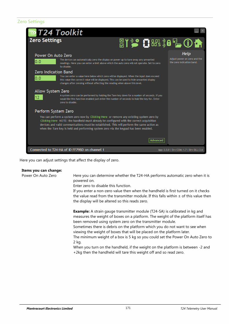
Mantracourt Electronics Limited T24 Telemetry User Manual 171
Zero Settings
Here you can adjust settings that affect the display of zero.
Items you can change:
Power On Auto Zero Here you can determine whether the T24-HA performs automatic zero when it is
powered on.
Enter zero to disable this function.
If you enter a non-zero value then when the handheld is first turned on it checks
the value read from the transmitter module. If this falls within ± of this value then
the display will be altered so this reads zero.
Example: A strain gauge transmitter module (T24-SA) is calibrated in kg and
measures the weight of boxes on a platform. The weight of the platform itself has
been removed using system zero on the transmitter module.
Sometimes there is debris on the platform which you do not want to see when
viewing the weight of boxes that will be placed on the platform later.
The minimum weight of a box is 5 kg so you could set the Power On Auto Zero to
2 kg.
When you turn on the handheld, if the weight on the platform is between -2 and
+2kg then the handheld will tare this weight off and so read zero.
Mantracourt Electronics Limited T24 Telemetry User Manual 172
Zero Indication Band Using this setting you can mask tiny changes in input after you press the Tare
button.
Entering zero will disable this function.
Entering a non-zero value will provide a band within which the display will always
read zero.
Once the reading exceeds this value the real weight will be displayed as no taring
is taking place.
Example: You are adding boxes to a platform and you press tare between adding
each one so you can see the weight of each box.
Without this setting activated each time you tare the display will be around zero
but not exactly zero (By setting the display resolution you may hide this
difference) by setting a small value here such as 0.2kg the display will show a
stable zero while actual weight is fluctuating less than ± 0.2kg.
Allow System Zero Entering a non-zero value here will enable system zero to be performed by
holding down the Tare key for a number of seconds.
The value entered here represents the number of seconds the Tare key needs to
be held.
Perform System Zero This section allows the user to apply or remove a system zero.
This will require that the transmitter modules are configured and attached to the
handheld and the entire system is ready for zeroing.
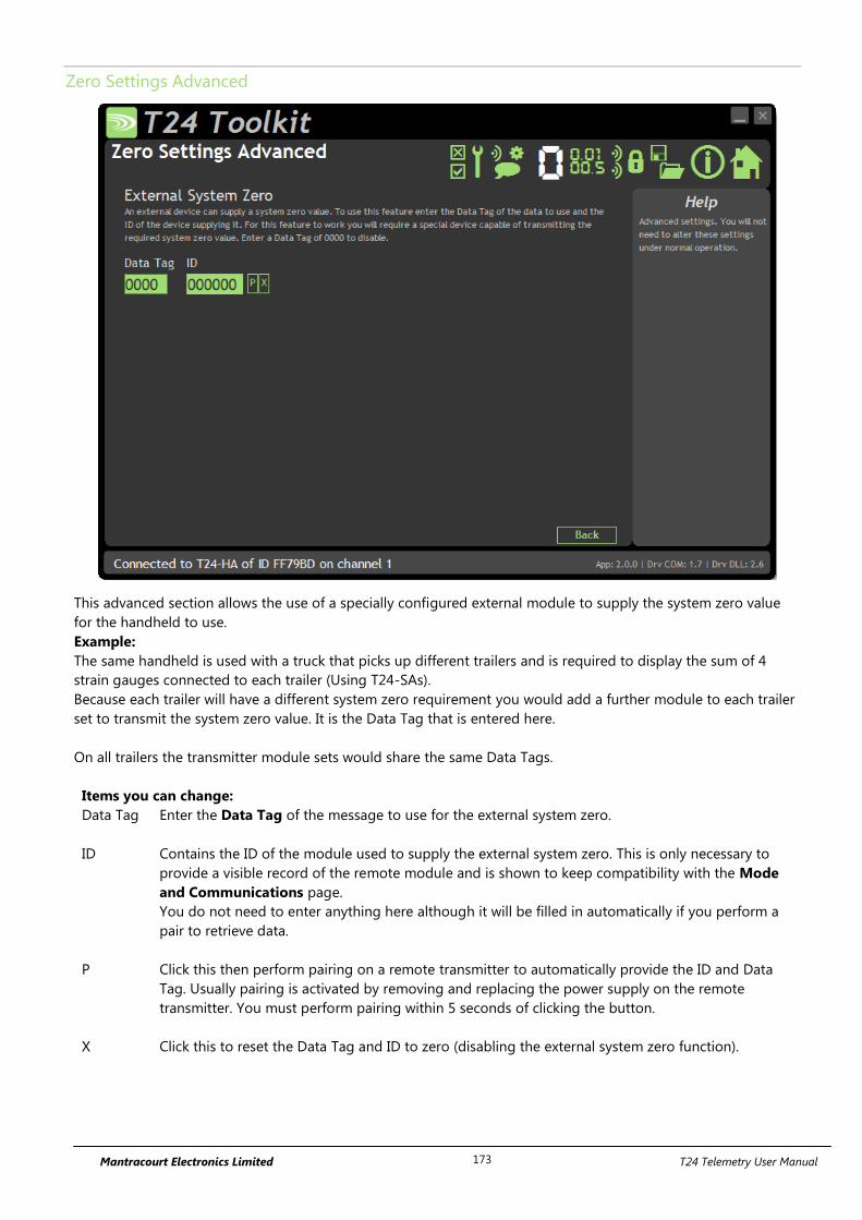
Mantracourt Electronics Limited T24 Telemetry User Manual 173
Zero Settings Advanced
This advanced section allows the use of a specially configured external module to supply the system zero value
for the handheld to use.
Example:
The same handheld is used with a truck that picks up different trailers and is required to display the sum of 4
strain gauges connected to each trailer (Using T24-SAs).
Because each trailer will have a different system zero requirement you would add a further module to each trailer
set to transmit the system zero value. It is the Data Tag that is entered here.
On all trailers the transmitter module sets would share the same Data Tags.
Items you can change:
Data Tag Enter the Data Tag of the message to use for the external system zero.
ID Contains the ID of the module used to supply the external system zero. This is only necessary to
provide a visible record of the remote module and is shown to keep compatibility with the Mode
and Communications page.
You do not need to enter anything here although it will be filled in automatically if you perform a
pair to retrieve data.
P Click this then perform pairing on a remote transmitter to automatically provide the ID and Data
Tag. Usually pairing is activated by removing and replacing the power supply on the remote
transmitter. You must perform pairing within 5 seconds of clicking the button.
X Click this to reset the Data Tag and ID to zero (disabling the external system zero function).
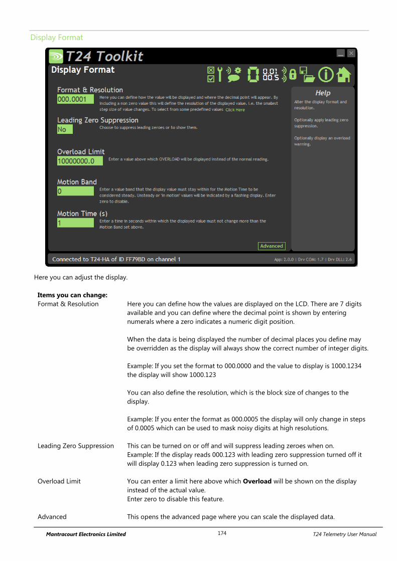
Mantracourt Electronics Limited T24 Telemetry User Manual 174
Display Format
Here you can adjust the display.
Items you can change:
Format & Resolution Here you can define how the values are displayed on the LCD. There are 7 digits
available and you can define where the decimal point is shown by entering
numerals where a zero indicates a numeric digit position.
When the data is being displayed the number of decimal places you define may
be overridden as the display will always show the correct number of integer digits.
Example: If you set the format to 000.0000 and the value to display is 1000.1234
the display will show 1000.123
You can also define the resolution, which is the block size of changes to the
display.
Example: If you enter the format as 000.0005 the display will only change in steps
of 0.0005 which can be used to mask noisy digits at high resolutions.
Leading Zero Suppression This can be turned on or off and will suppress leading zeroes when on.
Example: If the display reads 000.123 with leading zero suppression turned off it
will display 0.123 when leading zero suppression is turned on.
Overload Limit You can enter a limit here above which Overload will be shown on the display
instead of the actual value.
Enter zero to disable this feature.
Advanced This opens the advanced page where you can scale the displayed data.

Mantracourt Electronics Limited T24 Telemetry User Manual 175
Motion Band By entering a non-zero value here you activate the motion detection.
If, within the Motion Time, the displayed value changes by more than the amount
entered the reading will be deemed in motion or unstable and the display will
flash. The F1 key will be disabled while the reading is in motion.
Motion Time Enter a time in seconds within which the displayed value must not change more
than the Motion Band amount set above.
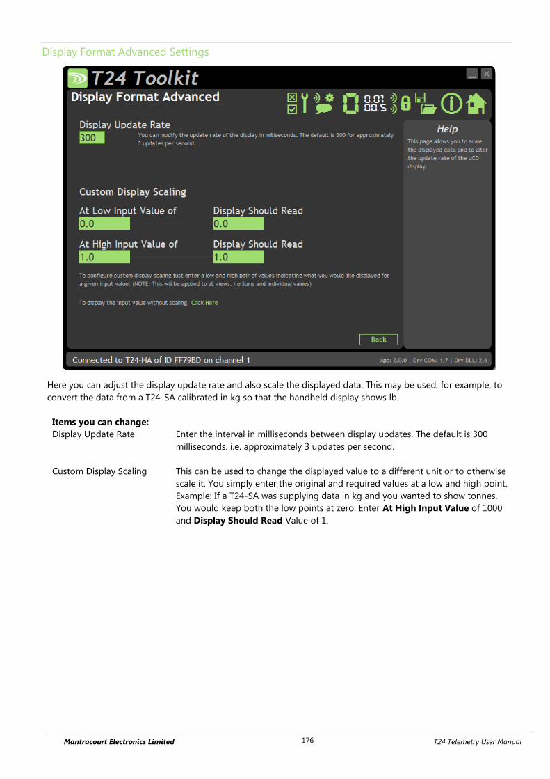
Mantracourt Electronics Limited T24 Telemetry User Manual 176
Display Format Advanced Settings
Here you can adjust the display update rate and also scale the displayed data. This may be used, for example, to
convert the data from a T24-SA calibrated in kg so that the handheld display shows lb.
Items you can change:
Display Update Rate Enter the interval in milliseconds between display updates. The default is 300
milliseconds. i.e. approximately 3 updates per second.
Custom Display Scaling This can be used to change the displayed value to a different unit or to otherwise
scale it. You simply enter the original and required values at a low and high point.
Example: If a T24-SA was supplying data in kg and you wanted to show tonnes.
You would keep both the low points at zero. Enter At High Input Value of 1000
and Display Should Read Value of 1.
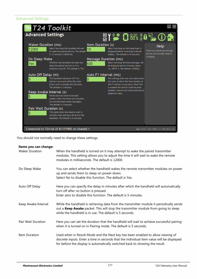
Mantracourt Electronics Limited T24 Telemetry User Manual 177
Advanced Settings
You should not normally need to change these settings.
Items you can change:
Waker Duration When the handheld is turned on it may attempt to wake the paired transmitter
modules. This setting allows you to adjust the time it will wait to wake the remote
modules in milliseconds. The default is 12000.
Do Sleep Wake You can select whether the handheld wakes the remote transmitter modules on power
up and sends them to sleep on power down.
Select No to disable this function. The default is Yes.
Auto Off Delay Here you can specify the delay in minutes after which the handheld will automatically
turn off after no button is pressed.
Enter zero to disable this function. The default is 5 minutes.
Keep Awake Interval While the handheld is retrieving data from the transmitter module it periodically sends
out a Keep Awake packet. This will stop the transmitter module from going to sleep
while the handheld is in use. The default is 5 seconds.
Pair Wait Duration Here you can set the duration that the handheld will wait to achieve successful pairing
when it is turned on in Pairing mode. The default is 5 seconds.
Item Duration Used when in Result Mode and the Next key has been enabled to allow viewing of
discrete inputs. Enter a time in seconds that the individual item value will be displayed
for before the display is automatically switched back to showing the result.

Mantracourt Electronics Limited T24 Telemetry User Manual 178
Message Duration Each time the Next key is used to step through available items the display shows a
brief description of the data about to be displayed. Input 1, Input 2, Result etc.
The time you enter here in milliseconds is the time that this message will be displayed
before the actual value is shown.
Newer versions of the handheld allow the user to define these message prompts. See
Prompts

Mantracourt Electronics Limited T24 Telemetry User Manual 179
Enclosure & Mounting
See Appendix A – Handheld Style section for more information.
Antennas
These modules have the antenna already fitted inside the enclosure so there are no specific mounting
requirements.
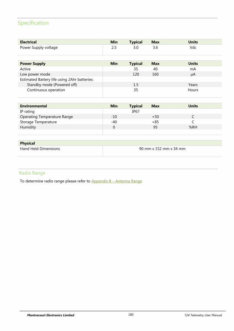
Mantracourt Electronics Limited T24 Telemetry User Manual 180
Specification
Electrical Min Typical Max Units
Power Supply voltage 2.5 3.0 3.6 Vdc
Power Supply Min Typical Max Units
Active 35 40 mA
Low power mode 120 160 µA
Estimated Battery life using 2Ahr batteries:
Standby mode (Powered off) 1.5 Years
Continuous operation 35 Hours
Environmental Min Typical Max Units
IP rating IP67
Operating Temperature Range -10 +50 C
Storage Temperature -40 +85 C
Humidity 0 95 %RH
Physical
Hand Held Dimensions 90 mm x 152 mm x 34 mm
Radio Range
To determine radio range please refer to Appendix B – Antenna Range
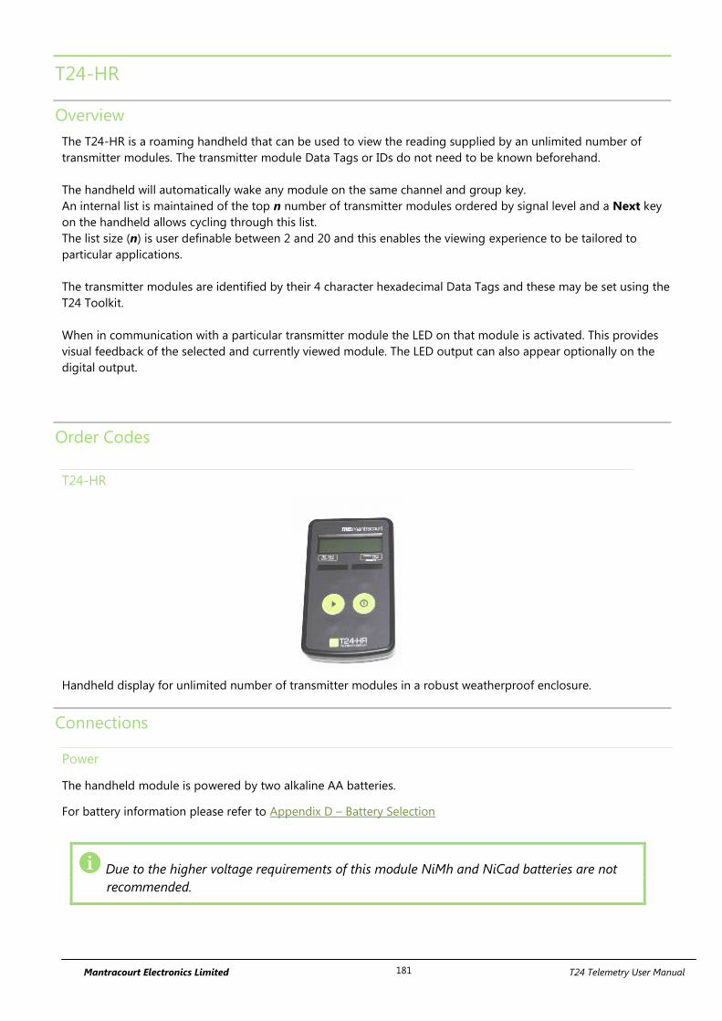
Mantracourt Electronics Limited T24 Telemetry User Manual 181
T24-HR
Overview
The T24-HR is a roaming handheld that can be used to view the reading supplied by an unlimited number of
transmitter modules. The transmitter module Data Tags or IDs do not need to be known beforehand.
The handheld will automatically wake any module on the same channel and group key.
An internal list is maintained of the top n number of transmitter modules ordered by signal level and a Next key
on the handheld allows cycling through this list.
The list size (n) is user definable between 2 and 20 and this enables the viewing experience to be tailored to
particular applications.
The transmitter modules are identified by their 4 character hexadecimal Data Tags and these may be set using the
T24 Toolkit.
When in communication with a particular transmitter module the LED on that module is activated. This provides
visual feedback of the selected and currently viewed module. The LED output can also appear optionally on the
digital output.
Order Codes
T24-HR
Handheld display for unlimited number of transmitter modules in a robust weatherproof enclosure.
Connections
Power
The handheld module is powered by two alkaline AA batteries.
For battery information please refer to Appendix D – Battery Selection
Due to the higher voltage requirements of this module NiMh and NiCad batteries are not
recommended.
Mantracourt Electronics Limited T24 Telemetry User Manual 182
Operation
View readings
As long as the transmitter module is on the same radio channel and share the same Group key settings as the
handheld you will be able to view the reading once the handheld is turned on.
If you need to change the channel of the transmitter module you will need to use the T24 Toolkit software or see
Pairing later in the manual.
Each time you press the Next key the handheld will cycle to the next transmitter module in its list of detected
modules. The Data Tag of the selected module will be displayed briefly before the reading is displayed.
To view the Data Tag of the currently viewed module press and hold the next key for around a second and the
Data Tag will be displayed and the reading will remain that of the current module without stepping on.
Keys
Power Key - Press and hold the power key for approximately 2 seconds then
release the key.
This will toggle between turning the handheld on and off.
Can also be used, by giving a quick press, to reset the Auto-Sleep delay.
Next Key – Pressing and releasing selects the next transmitter to view.
Pressing and holding will display the currently viewed transmitter Data Tag
without moving to the next transmitter.
Indicators
SIG LOW The radio signal from the transmitter module is low. The module is still
functioning but the limit of the range may be near. Communications may start to
deteriorate when this indicator is visible. Until ------ is displayed the
communications are still OK and the display can be relied on for accuracy.
Even with a degraded signal the display value will always be
correct.
BATT LOW The batteries in the handheld are low and need to be replaced.
REMOTE ERROR The transmitter module has an error that the handheld does not recognise.
REMOTE BATT LOW The battery or supply to the transmitter module is low.
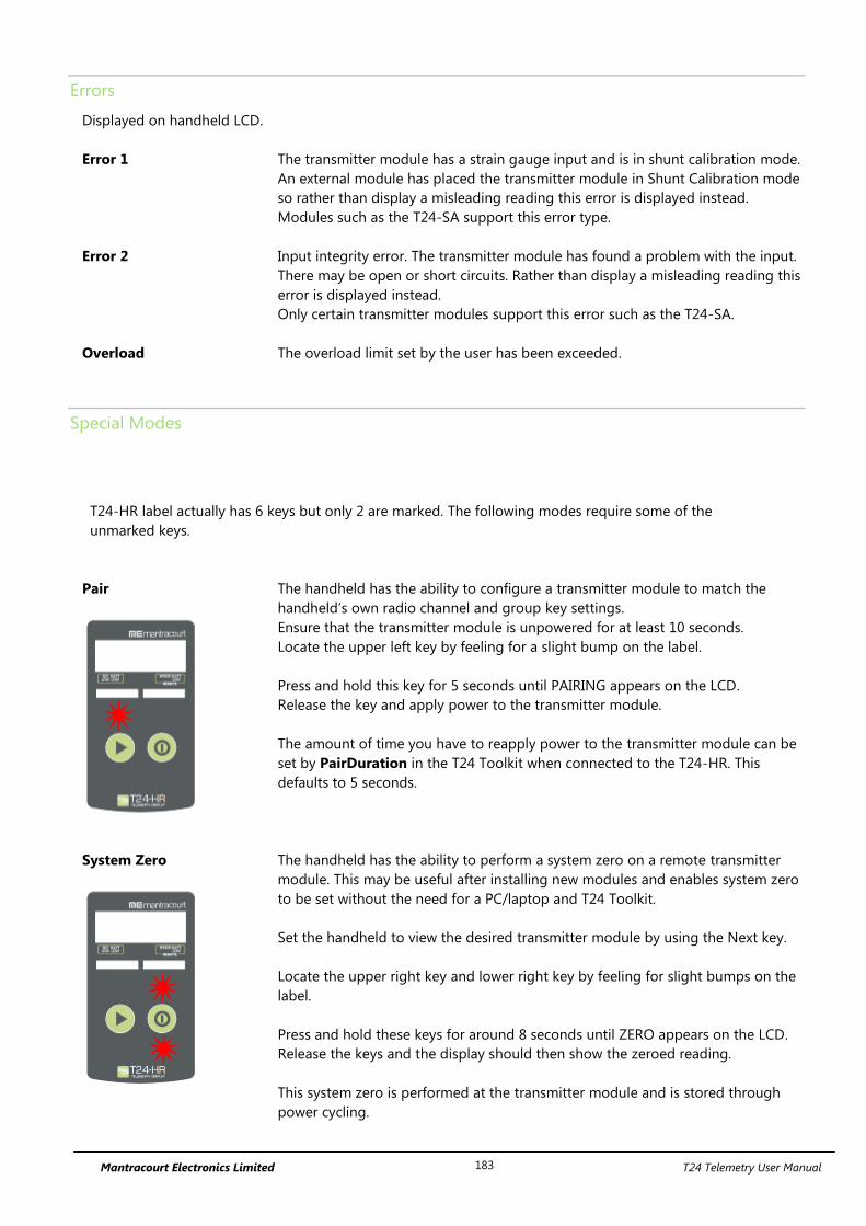
Mantracourt Electronics Limited T24 Telemetry User Manual 183
Errors
Displayed on handheld LCD.
Error 1 The transmitter module has a strain gauge input and is in shunt calibration mode.
An external module has placed the transmitter module in Shunt Calibration mode
so rather than display a misleading reading this error is displayed instead.
Modules such as the T24-SA support this error type.
Error 2 Input integrity error. The transmitter module has found a problem with the input.
There may be open or short circuits. Rather than display a misleading reading this
error is displayed instead.
Only certain transmitter modules support this error such as the T24-SA.
Overload The overload limit set by the user has been exceeded.
Special Modes
T24-HR label actually has 6 keys but only 2 are marked. The following modes require some of the
unmarked keys.
Pair
The handheld has the ability to configure a transmitter module to match the
handheld’s own radio channel and group key settings.
Ensure that the transmitter module is unpowered for at least 10 seconds.
Locate the upper left key by feeling for a slight bump on the label.
Press and hold this key for 5 seconds until PAIRING appears on the LCD.
Release the key and apply power to the transmitter module.
The amount of time you have to reapply power to the transmitter module can be
set by PairDuration in the T24 Toolkit when connected to the T24-HR. This
defaults to 5 seconds.
System Zero
The handheld has the ability to perform a system zero on a remote transmitter
module. This may be useful after installing new modules and enables system zero
to be set without the need for a PC/laptop and T24 Toolkit.
Set the handheld to view the desired transmitter module by using the Next key.
Locate the upper right key and lower right key by feeling for slight bumps on the
label.
Press and hold these keys for around 8 seconds until ZERO appears on the LCD.
Release the keys and the display should then show the zeroed reading.
This system zero is performed at the transmitter module and is stored through
power cycling.
Mantracourt Electronics Limited T24 Telemetry User Manual 184
Transmitter Module Configuration
Unless the transmitter modules are permanently powered their Sleep Delay setting should be set to a non-zero
value so that the module returns to deep sleep when the handheld is turned off or goes out of range. It is
suggested that this time is set to at least 3 times the interval between its data transmissions but can be longer.
i.e. If the default transmission rate is 333ms (3Hz) choose a Sleep Delay of around 5 seconds. This is a good
battery saving time that will ensure the transmitter stays awake even if out of range of the handheld temporarily.
Most transmitter modules allow the LED state to be echoed to the digital output line which allows an external LED
to be fitted. This is useful when requiring visual feedback of the module the handheld is currently viewing.
The handheld displays the data at the rate that the transmitter module is configured to supply. The ideal rate is
about 3hz which is the default but the handheld will operate quite happily with modules with a data delivery rate
of down to around 1 every 30 seconds. Just remember to set the Timeout of the handheld to at least 3 times this
period. (i.e. 91 seconds in the case of 30 second transmission interval).
The handheld will wake any sleeping module if it is on the same channel and has the same
group key.
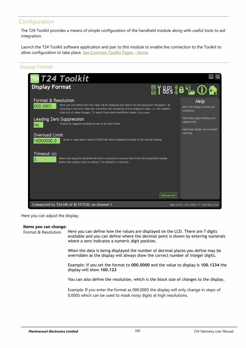
Mantracourt Electronics Limited T24 Telemetry User Manual 185
Configuration
The T24 Toolkit provides a means of simple configuration of the handheld module along with useful tools to aid
integration.
Launch the T24 Toolkit software application and pair to this module to enable the connection to the Toolkit to
allow configuration to take place. See Common Toolkit Pages - Home
Display Format
Here you can adjust the display.
Items you can change:
Format & Resolution Here you can define how the values are displayed on the LCD. There are 7 digits available and you can define where the decimal point is shown by entering numerals where a zero indicates a numeric digit position. When the data is being displayed the number of decimal places you define may be overridden as the display will always show the correct number of integer digits. Example: If you set the format to 000.0000 and the value to display is 100.1234 the display will show 100.123 You can also define the resolution, which is the block size of changes to the display.
Example: If you enter the format as 000.0005 the display will only change in steps of
0.0005 which can be used to mask noisy digits at high resolutions.

Mantracourt Electronics Limited T24 Telemetry User Manual 186
Leading Zero
Suppression
This can be turned on or off and will suppress leading zeroes when on.
Example: If the display reads 000.123 with leading zero suppression turned off it will
display 0.123 when leading zero suppression is turned on.
Overload Limit You can enter a limit here above which Overload will be shown on the display instead
of the actual value.
Enter zero to disable this feature.
Timeout Enter the timeout in seconds. This sets the time allowed without any data arriving from
the viewed module before all dashes are displayed on the LCD. Should be at least 3
times the interval between the messages being sent by the transmitter module.
Advanced This opens the advanced page where you can scale the displayed data.
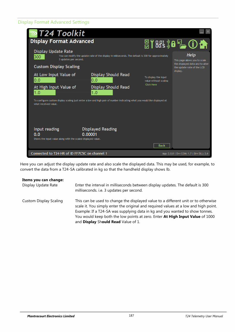
Mantracourt Electronics Limited T24 Telemetry User Manual 187
Display Format Advanced Settings
Here you can adjust the display update rate and also scale the displayed data. This may be used, for example, to
convert the data from a T24-SA calibrated in kg so that the handheld display shows lb.
Items you can change:
Display Update Rate Enter the interval in milliseconds between display updates. The default is 300
milliseconds. i.e. 3 updates per second.
Custom Display Scaling This can be used to change the displayed value to a different unit or to otherwise
scale it. You simply enter the original and required values at a low and high point.
Example: If a T24-SA was supplying data in kg and you wanted to show tonnes.
You would keep both the low points at zero. Enter At High Input Value of 1000
and Display Should Read Value of 1.
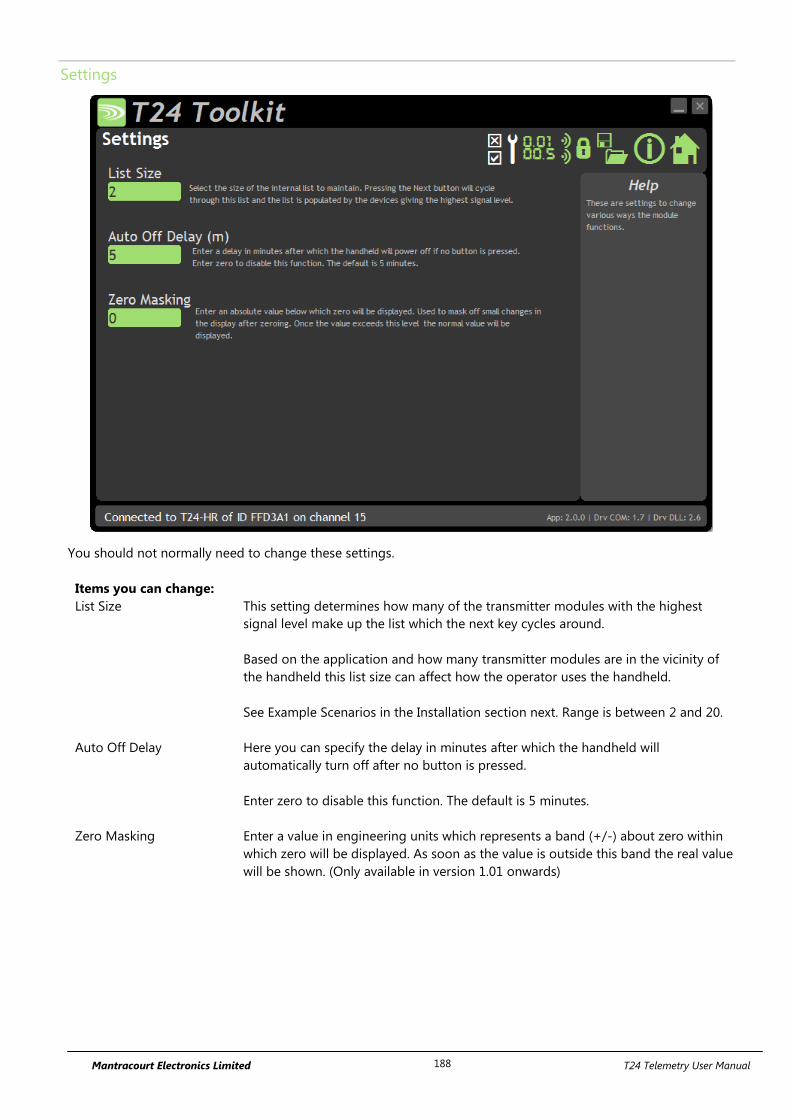
Mantracourt Electronics Limited T24 Telemetry User Manual 188
Settings
You should not normally need to change these settings.
Items you can change:
List Size This setting determines how many of the transmitter modules with the highest
signal level make up the list which the next key cycles around.
Based on the application and how many transmitter modules are in the vicinity of
the handheld this list size can affect how the operator uses the handheld.
See Example Scenarios in the Installation section next. Range is between 2 and 20.
Auto Off Delay Here you can specify the delay in minutes after which the handheld will
automatically turn off after no button is pressed.
Enter zero to disable this function. The default is 5 minutes.
Zero Masking Enter a value in engineering units which represents a band (+/-) about zero within
which zero will be displayed. As soon as the value is outside this band the real value
will be shown. (Only available in version 1.01 onwards)
Mantracourt Electronics Limited T24 Telemetry User Manual 189
Example Installation Scenarios
The following example scenarios explain the usage of the handheld and transmitter modules and lists the
important settings chosen to achieve this.
Scenario 1 – 200 transmitter modules are spaced at 1 meter intervals along a bridge.
The modules spend most of their time in deep sleep and are only activated when the operator uses the handheld.
The transmitter modules are set for a message interval of 333 milliseconds (3Hz) and have a sleep delay of 5
seconds.
On the T24-HR setting the List Size to 6 allows the operator a fast responding Next key that cycles through the
closest 6 modules to allow the operator to note any out of limit readings. The operator checks the Data Tag
displayed on the handheld as the Next key is pressed against the Data Tag painted on the modules affixed to the
bridge.
The operator walks the length of the bridge and stops approximately every 6 meters and quickly scrolls through
the small list size and records the readings of the 6 local modules.
The list dynamically repopulates as he walks along the length of the bridge.
During the walk modules are automatically woken by the handheld as they enter range and as the operator walks
out of range the modules automatically return to sleep.
Scenario 2 – The operator has 3 rooms to monitor.
Each room contains 10 transmitter modules. These modules are always fully awake but operate at a transmission
interval of 10 seconds. There is another module that is logging the data from these modules so their sleep delay
is set to zero to disable that function.
By setting the List Size to 10 the operator can enter the desired room and simply cycle through the 10 modules
present in that room.
Because the transmitter modules only send messages at 10 second intervals it can take up to 10 seconds for a
particular module to be available from the handheld. The timeout on the handheld is set to 31 seconds.
The input to the transmitter modules is very slow to change so although the displayed value only updates every
10 seconds the operator is still seeing a valid reading as he cycles through the transmitter modules. The timeout
of 31 seconds allows for the odd dropped reading but if a module dropped out permanently for whatever reason
the handheld would display ------- after 31 seconds or the module would never appear in the list if it had not
transmitted since the handheld had been turned on.
Scenario 3 – 500 pallets are stored in a warehouse.
Each pallet has a T24-SA transmitter module built in that transmits the weight on the pallet. The T24-SA modules
have been configured so that the LED state is echoed onto the digital output and this is used to power a high
brightness blue LED attached to the front of the pallet. The module transmission intervals are set to 3 per second
and a sleep delay of 10 seconds. The LED flashes at 3Hz while the module is awake and is off when asleep. When
the handheld is displaying the reading from the module its LED is on constantly.
On the handheld the List Size is set to 1. This has the effect of allowing the operator to approach the desired
pallet and press the Next key. This will effectively select the module with the highest radio signal which will be
the one the operator is standing next to and the LED will light to provide visual feedback so the operator knows
he is looking at the correct pallet.
The operator moves to the next pallet and presses the Next key again at which point the previous pallet LED goes
off and the closest pallet LED activates.
As the operator moves out of range, pallets go back to sleep because of their sleep delay settings.

Mantracourt Electronics Limited T24 Telemetry User Manual 190
Enclosure & Mounting
See Appendix A – Handheld Style section for more information.
Antennas
These modules have the antenna already fitted inside the enclosure so there are no specific mounting
requirements.
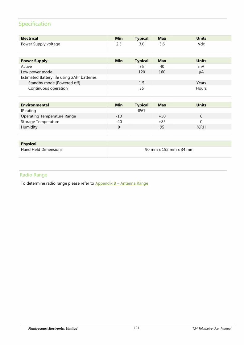
Mantracourt Electronics Limited T24 Telemetry User Manual 191
Specification
Electrical Min Typical Max Units
Power Supply voltage 2.5 3.0 3.6 Vdc
Power Supply Min Typical Max Units
Active 35 40 mA
Low power mode 120 160 µA
Estimated Battery life using 2Ahr batteries:
Standby mode (Powered off) 1.5 Years
Continuous operation 35 Hours
Environmental Min Typical Max Units
IP rating IP67
Operating Temperature Range -10 +50 C
Storage Temperature -40 +85 C
Humidity 0 95 %RH
Physical
Hand Held Dimensions 90 mm x 152 mm x 34 mm
Radio Range
To determine radio range please refer to Appendix B – Antenna Range
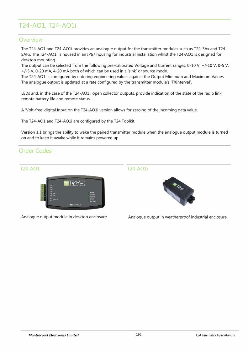
Mantracourt Electronics Limited T24 Telemetry User Manual 192
T24-AO1, T24-AO1i
Overview
The T24-AO1 and T24-AO1i provides an analogue output for the transmitter modules such as T24-SAx and T24-
SAFx. The T24-AO1i is housed in an IP67 housing for industrial installation whilst the T24-AO1 is designed for
desktop mounting.
The output can be selected from the following pre-calibrated Voltage and Current ranges. 0-10 V, +/-10 V, 0-5 V,
+/-5 V, 0-20 mA, 4-20 mA both of which can be used in a ‘sink’ or source mode.
The T24-AO1 is configured by entering engineering values against the Output Minimum and Maximum Values.
The analogue output is updated at a rate configured by the transmitter module’s ‘TXInterval’.
LEDs and, in the case of the T24-AO1i, open collector outputs, provide indication of the state of the radio link,
remote battery life and remote status.
A ‘Volt-free’ digital Input on the T24-AO1i version allows for zeroing of the incoming data value.
The T24-AO1 and T24-AO1i are configured by the T24 Toolkit.
Version 1.1 brings the ability to wake the paired transmitter module when the analogue output module is turned
on and to keep it awake while it remains powered up.
Order Codes
T24-AO1
Analogue output module in desktop enclosure.
T24-AO1i
Analogue output in weatherproof industrial enclosure.
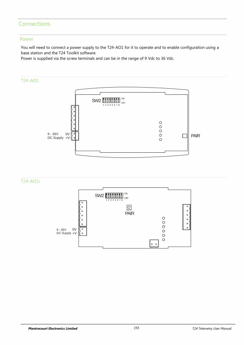
Mantracourt Electronics Limited T24 Telemetry User Manual 193
Connections
Power
You will need to connect a power supply to the T24-AO1 for it to operate and to enable configuration using a
base station and the T24 Toolkit software.
Power is supplied via the screw terminals and can be in the range of 9 Vdc to 36 Vdc.
T24-AO1
0V+V
1 2 3 4 5 6 7 8
ON
OFFSW2
PAIR9 - 36VDC Supply
T24-AO1i
0V+V
9 - 36VDC Supply
1 2 3 4 5 6 7 8
ON
OFFSW2
PAIR
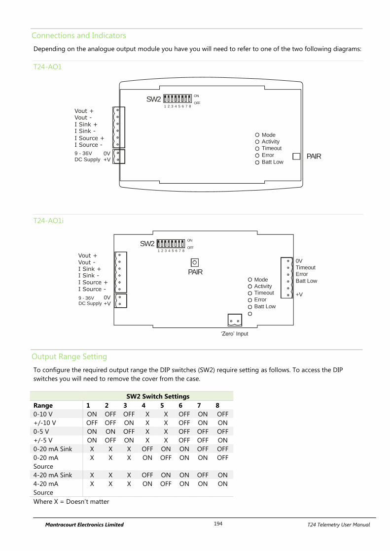
Mantracourt Electronics Limited T24 Telemetry User Manual 194
Connections and Indicators
Depending on the analogue output module you have you will need to refer to one of the two following diagrams:
T24-AO1
Mode
Activity
Timeout
Error
Batt Low
Vout +Vout -
I Sink +I Sink -
I Source +I Source -
0V+V
1 2 3 4 5 6 7 8
ON
OFFSW2
PAIR9 - 36VDC Supply
T24-AO1i
Vout +
Vout -I Sink +I Sink -
I Source +
I Source -
0V
Timeout
Error
Batt Low
+V
‘Zero’ Input
Mode
Activity
Timeout
Error
Batt Low
0V+V
9 - 36VDC Supply
1 2 3 4 5 6 7 8
ON
OFFSW2
PAIR
Output Range Setting
To configure the required output range the DIP switches (SW2) require setting as follows. To access the DIP
switches you will need to remove the cover from the case.
SW2 Switch Settings
Range 1 2 3 4 5 6 7 8
0-10 V ON OFF OFF X X OFF ON OFF
+/-10 V OFF OFF ON X X OFF ON ON
0-5 V ON ON OFF X X OFF OFF OFF
+/-5 V ON OFF ON X X OFF OFF ON
0-20 mA Sink X X X OFF ON ON OFF OFF
0-20 mA
Source
X X X ON OFF ON ON OFF
4-20 mA Sink X X X OFF ON ON OFF ON
4-20 mA
Source
X X X ON OFF ON ON ON
Where X = Doesn’t matter
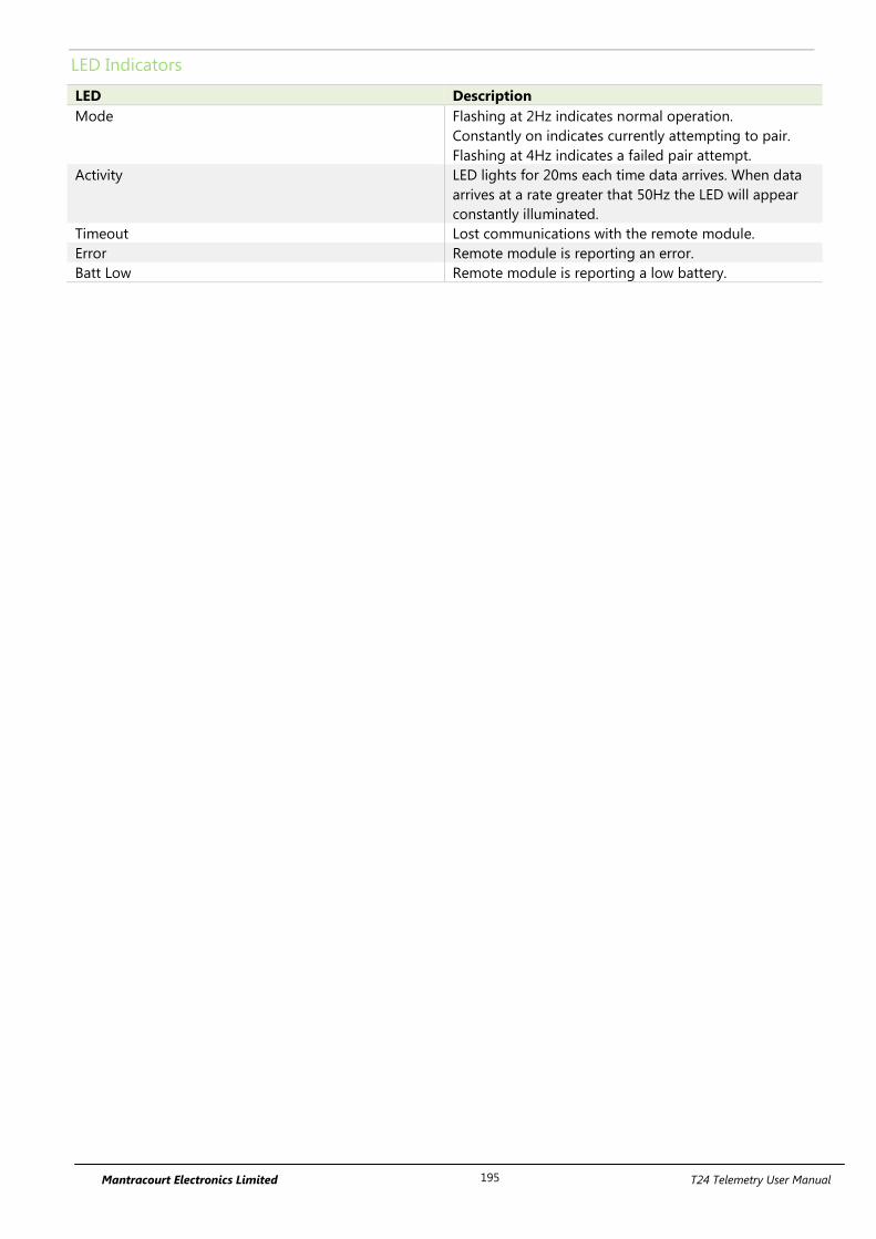
Mantracourt Electronics Limited T24 Telemetry User Manual 195
LED Indicators
LED Description
Mode Flashing at 2Hz indicates normal operation.
Constantly on indicates currently attempting to pair.
Flashing at 4Hz indicates a failed pair attempt.
Activity LED lights for 20ms each time data arrives. When data
arrives at a rate greater that 50Hz the LED will appear
constantly illuminated.
Timeout Lost communications with the remote module.
Error Remote module is reporting an error.
Batt Low Remote module is reporting a low battery.
Mantracourt Electronics Limited T24 Telemetry User Manual 196
Configuration
The T24-AO1 is configured by setting the Data Tag of the module whose data you wish to reflect onto the
analogue output.
Once you know the data tag you then need to work out which calibrated values from the transmitter module you
want represented by the selected analogue output minimum and maximum levels.
For example: A T24-SA has been calibrated to give 0 to 10 tonnes output. You have selected a 4-20mA analogue
output and want the output to give 4mA at 0 tonnes and 20mA at 8 tonnes. Simply set the In Minimum to 0 and
In Maximum to 8.
Next you set the desired actions when errors occur.
To associate the T24-AO1 with a transmitter module you just need to let the T24-AO1 know the Data Tag of the
data to use.
This can be done manually using the T24 Toolkit (See below) or this can be achieved using the Pair button of the
T24-AO1.
When first configuring the T24-AO1 it really makes no difference which technique is used but if you were
replacing a data transmitter module in the field the switch technique would negate the need for the Toolkit or a
base station.
To perform a ‘pair’ first remove the power from the transmitter module. Next, press the Pair Switch on the T24-
AO1 then within 10 seconds re-apply power to the transmitter module. The mode LED will indicate the success or
failure of this operation (See above table).
To access the Pair Switch on a T24-AO1i you need to remove the lid. The Pair Switch can be
accessed through a hole in the end of the case on a T24-AO1; a straightened paper clip
could be used.
An advantage of using the Pair Switch is that you can pair to any transmitter module regardless of its radio
channel or group key settings. When you pair the transmitter module settings will be changed to match those of
the T24-AO1. If you manually enter the Data Tag using the T24-Toolkit you will need to ensure that both the
transmitter module and the T24-AO1 are on the same radio channel and are using the same group key.
T24 Toolkit
The T24 Toolkit provides a means of simple configuration and calibration of the module along with useful tools to
aid integration.
Launch the T24 Toolkit software application and pair to this module to enable the connection to the Toolkit to
allow configuration to take place. See Common Toolkit Pages - Home
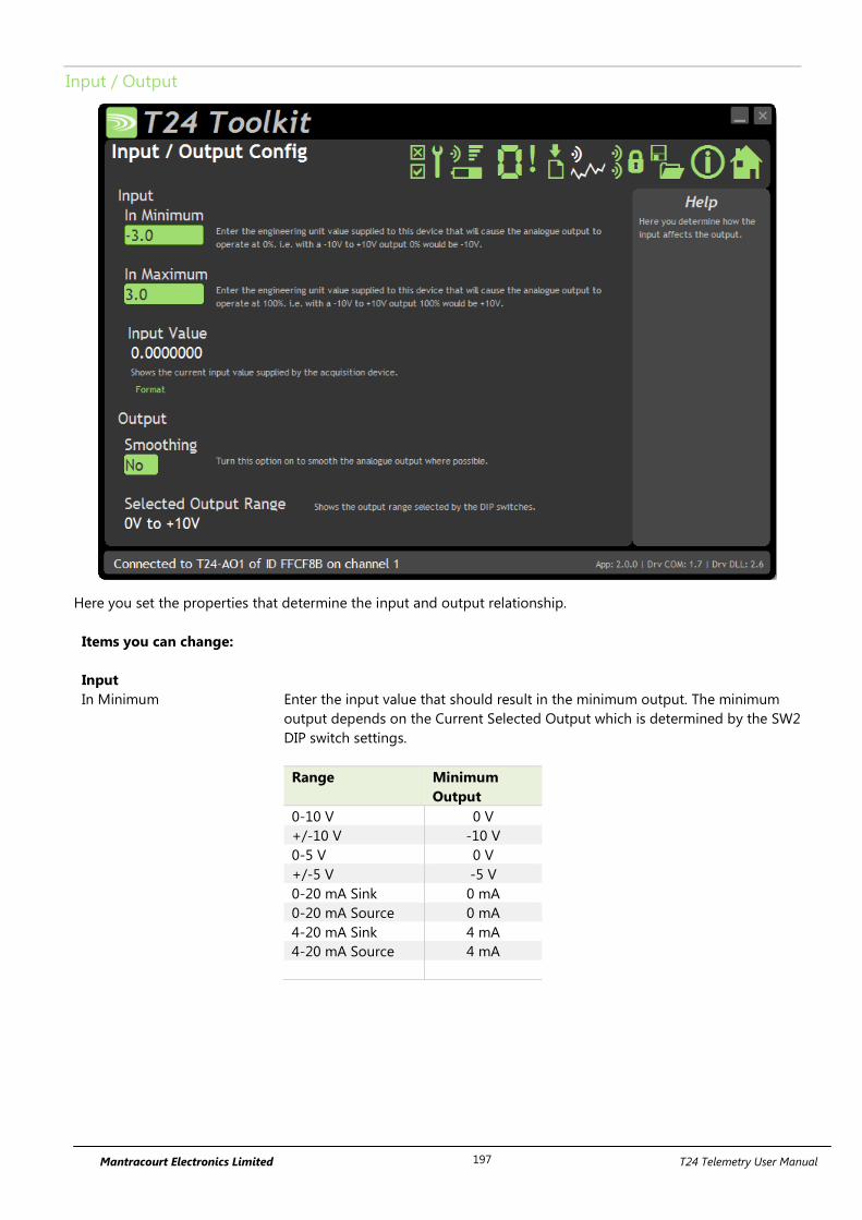
Mantracourt Electronics Limited T24 Telemetry User Manual 197
Input / Output
Here you set the properties that determine the input and output relationship.
Items you can change:
Input
In Minimum Enter the input value that should result in the minimum output. The minimum
output depends on the Current Selected Output which is determined by the SW2
DIP switch settings.
Range Minimum
Output
0-10 V 0 V
+/-10 V -10 V
0-5 V 0 V
+/-5 V -5 V
0-20 mA Sink 0 mA
0-20 mA Source 0 mA
4-20 mA Sink 4 mA
4-20 mA Source 4 mA
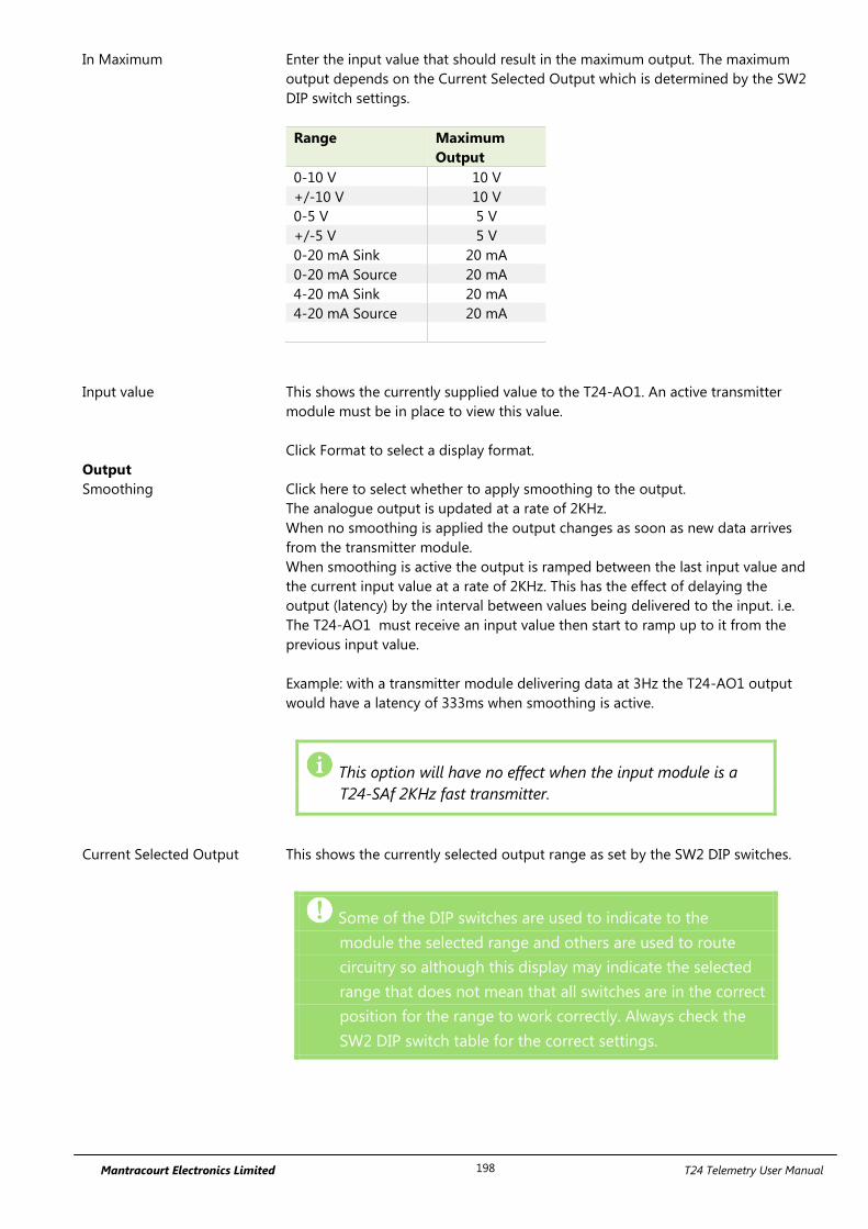
Mantracourt Electronics Limited T24 Telemetry User Manual 198
In Maximum Enter the input value that should result in the maximum output. The maximum
output depends on the Current Selected Output which is determined by the SW2
DIP switch settings.
Range Maximum
Output
0-10 V 10 V
+/-10 V 10 V
0-5 V 5 V
+/-5 V 5 V
0-20 mA Sink 20 mA
0-20 mA Source 20 mA
4-20 mA Sink 20 mA
4-20 mA Source 20 mA
Input value This shows the currently supplied value to the T24-AO1. An active transmitter
module must be in place to view this value.
Click Format to select a display format.
Output
Smoothing Click here to select whether to apply smoothing to the output.
The analogue output is updated at a rate of 2KHz.
When no smoothing is applied the output changes as soon as new data arrives
from the transmitter module.
When smoothing is active the output is ramped between the last input value and
the current input value at a rate of 2KHz. This has the effect of delaying the
output (latency) by the interval between values being delivered to the input. i.e.
The T24-AO1 must receive an input value then start to ramp up to it from the
previous input value.
Example: with a transmitter module delivering data at 3Hz the T24-AO1 output
would have a latency of 333ms when smoothing is active.
This option will have no effect when the input module is a
T24-SAf 2KHz fast transmitter.
Current Selected Output This shows the currently selected output range as set by the SW2 DIP switches.
Some of the DIP switches are used to indicate to the
module the selected range and others are used to route
circuitry so although this display may indicate the selected
range that does not mean that all switches are in the correct
position for the range to work correctly. Always check the
SW2 DIP switch table for the correct settings.
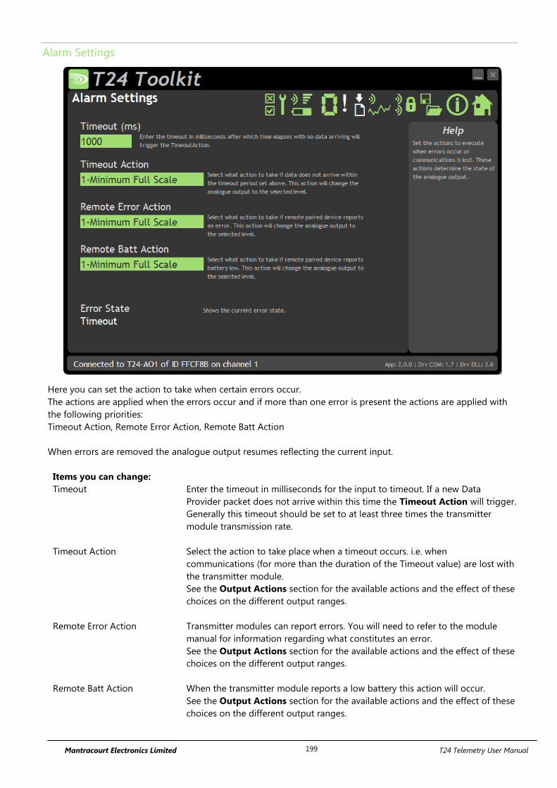
Mantracourt Electronics Limited T24 Telemetry User Manual 199
Alarm Settings
Here you can set the action to take when certain errors occur.
The actions are applied when the errors occur and if more than one error is present the actions are applied with
the following priorities:
Timeout Action, Remote Error Action, Remote Batt Action
When errors are removed the analogue output resumes reflecting the current input.
Items you can change:
Timeout Enter the timeout in milliseconds for the input to timeout. If a new Data
Provider packet does not arrive within this time the Timeout Action will trigger.
Generally this timeout should be set to at least three times the transmitter
module transmission rate.
Timeout Action Select the action to take place when a timeout occurs. i.e. when
communications (for more than the duration of the Timeout value) are lost with
the transmitter module.
See the Output Actions section for the available actions and the effect of these
choices on the different output ranges.
Remote Error Action Transmitter modules can report errors. You will need to refer to the module
manual for information regarding what constitutes an error.
See the Output Actions section for the available actions and the effect of these
choices on the different output ranges.
Remote Batt Action When the transmitter module reports a low battery this action will occur.
See the Output Actions section for the available actions and the effect of these
choices on the different output ranges.
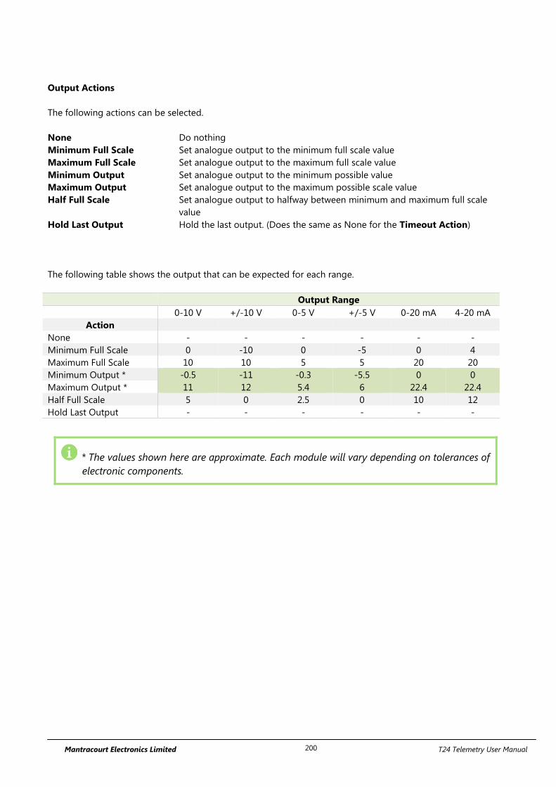
Mantracourt Electronics Limited T24 Telemetry User Manual 200
Output Actions
The following actions can be selected.
None Do nothing
Minimum Full Scale Set analogue output to the minimum full scale value
Maximum Full Scale Set analogue output to the maximum full scale value
Minimum Output Set analogue output to the minimum possible value
Maximum Output Set analogue output to the maximum possible scale value
Half Full Scale Set analogue output to halfway between minimum and maximum full scale
value
Hold Last Output Hold the last output. (Does the same as None for the Timeout Action)
The following table shows the output that can be expected for each range.
Output Range
0-10 V +/-10 V 0-5 V +/-5 V 0-20 mA 4-20 mA
Action
None - - - - - -
Minimum Full Scale 0 -10 0 -5 0 4
Maximum Full Scale 10 10 5 5 20 20
Minimum Output * -0.5 -11 -0.3 -5.5 0 0
Maximum Output * 11 12 5.4 6 22.4 22.4
Half Full Scale 5 0 2.5 0 10 12
Hold Last Output - - - - - -
* The values shown here are approximate. Each module will vary depending on tolerances of
electronic components.
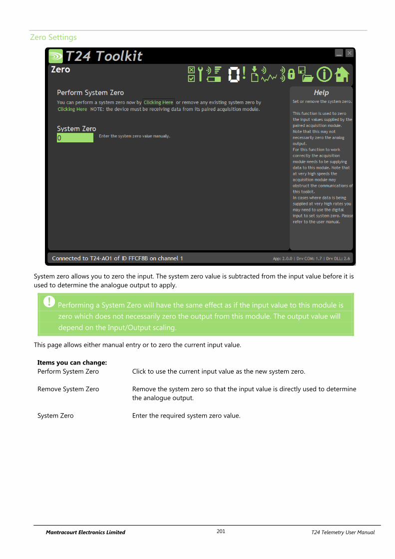
Mantracourt Electronics Limited T24 Telemetry User Manual 201
Zero Settings
System zero allows you to zero the input. The system zero value is subtracted from the input value before it is
used to determine the analogue output to apply.
Performing a System Zero will have the same effect as if the input value to this module is
zero which does not necessarily zero the output from this module. The output value will
depend on the Input/Output scaling.
This page allows either manual entry or to zero the current input value.
Items you can change:
Perform System Zero Click to use the current input value as the new system zero.
Remove System Zero Remove the system zero so that the input value is directly used to determine
the analogue output.
System Zero Enter the required system zero value.
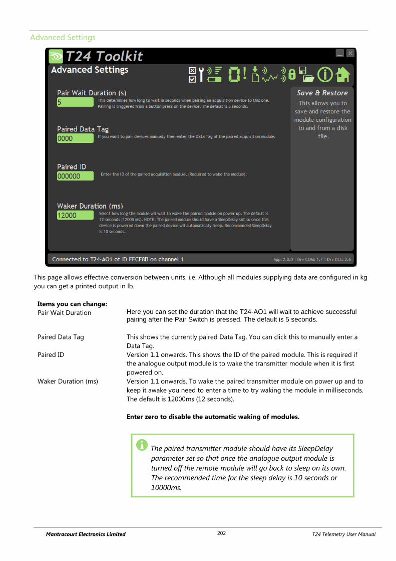
Mantracourt Electronics Limited T24 Telemetry User Manual 202
Advanced Settings
This page allows effective conversion between units. i.e. Although all modules supplying data are configured in kg
you can get a printed output in lb.
Items you can change:
Pair Wait Duration Here you can set the duration that the T24-AO1 will wait to achieve successful pairing after the Pair Switch is pressed. The default is 5 seconds.
Paired Data Tag This shows the currently paired Data Tag. You can click this to manually enter a
Data Tag.
Paired ID Version 1.1 onwards. This shows the ID of the paired module. This is required if
the analogue output module is to wake the transmitter module when it is first
powered on.
Waker Duration (ms) Version 1.1 onwards. To wake the paired transmitter module on power up and to
keep it awake you need to enter a time to try waking the module in milliseconds.
The default is 12000ms (12 seconds).
Enter zero to disable the automatic waking of modules.
The paired transmitter module should have its SleepDelay
parameter set so that once the analogue output module is
turned off the remote module will go back to sleep on its own.
The recommended time for the sleep delay is 10 seconds or
10000ms.
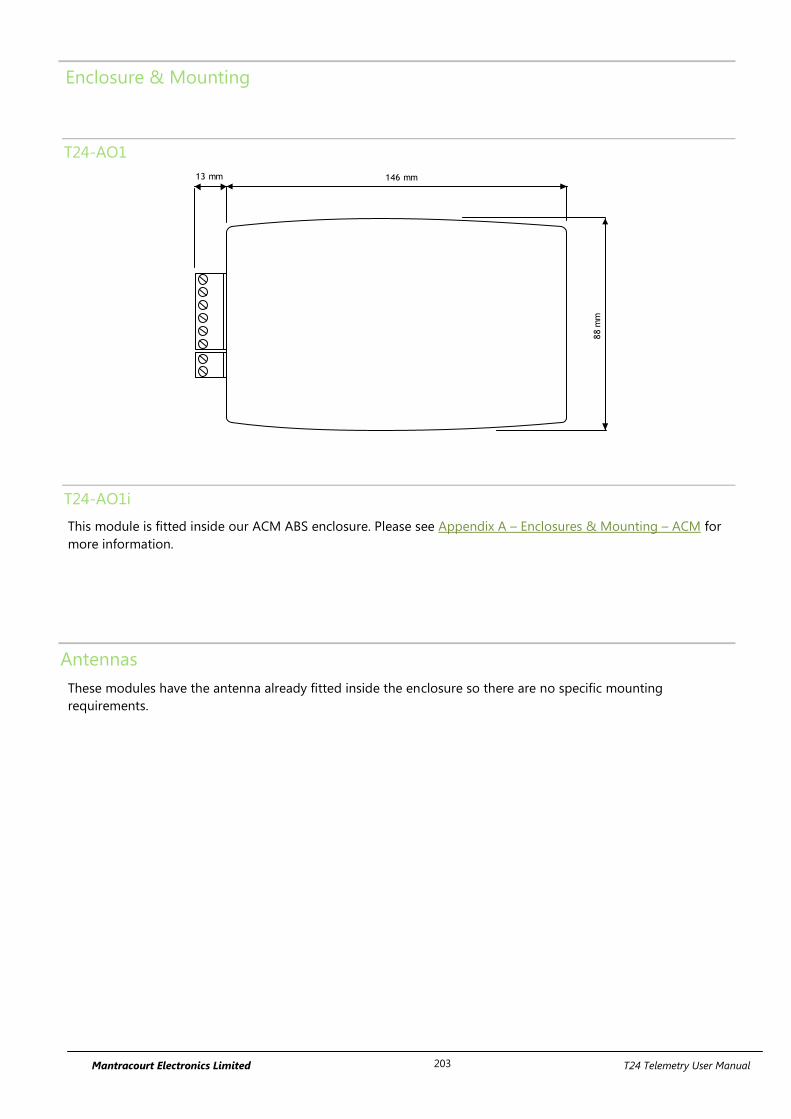
Mantracourt Electronics Limited T24 Telemetry User Manual 203
Enclosure & Mounting
T24-AO1
146 mm13 mm
88
mm
T24-AO1i
This module is fitted inside our ACM ABS enclosure. Please see Appendix A – Enclosures & Mounting – ACM for
more information.
Antennas
These modules have the antenna already fitted inside the enclosure so there are no specific mounting
requirements.

Mantracourt Electronics Limited T24 Telemetry User Manual 204
Specification
Parameter Minimum Typical Maximum Units Notes
External Supply voltage Range 9 12 32 Vdc
Operational Current - 85 150 mA
Operating Temperature Range -20 - 55 °C
Storage Temperature Range -40 - 85 °C
Reverse polarity Protection - - -32 Vdc Maximum Supply level
Digital output Drive voltage 30 Vdc
Digital output Drive Current 20 mA
Source Impedance driving
Digital Input (volt-free contact)
200 Ω
Voltage output
Resolution 16 Bits
output gain stability - 0.008 0.015 ± % FS/°C
output zero stability - 0.005 0.015 ± % FS/°C
Short term stability (1 hr) - 0.003 0.01 ± % FS
Long term stability (10k hrs) - 0.03 0.1 ± % FS
Residual ripple 40 mV p-p
Minimum load impedance 5000 Ω
Linearity
- 0.007 0.01 ± % FS
Current output
Resolution 16 Bits
4-20mA output gain stability - 0.006 0.03 ± % FS/°C
4-20mA output zero stability - 0.003 0.02 ± % FS/°C
Short term stability (1 hr) - 0.006 0.03 ± % FS
Long term stability (10k hrs) - 0.06 0.2 ± % FS
Residual ripple 0.032 mA p-p
Settling time to ±0.5µA (thermal
effects)
- 5 - secs
Maximum load impedance 500 Ω
Linearity
- 0.01 0.02 ± % FS
Physical Dimensions
T24-AO1 166 X 87 X 26 mm
T24-AO1i 190 X 80 X 55 mm
Environmental
T24-AO1 IP50
T24-AO1i IP67
Humidity 95%RH (max)
Radio Range
To determine T24-AO1i radio range please refer to Appendix B – Antenna Range
The T24-AO1 has a maximum range of 100m
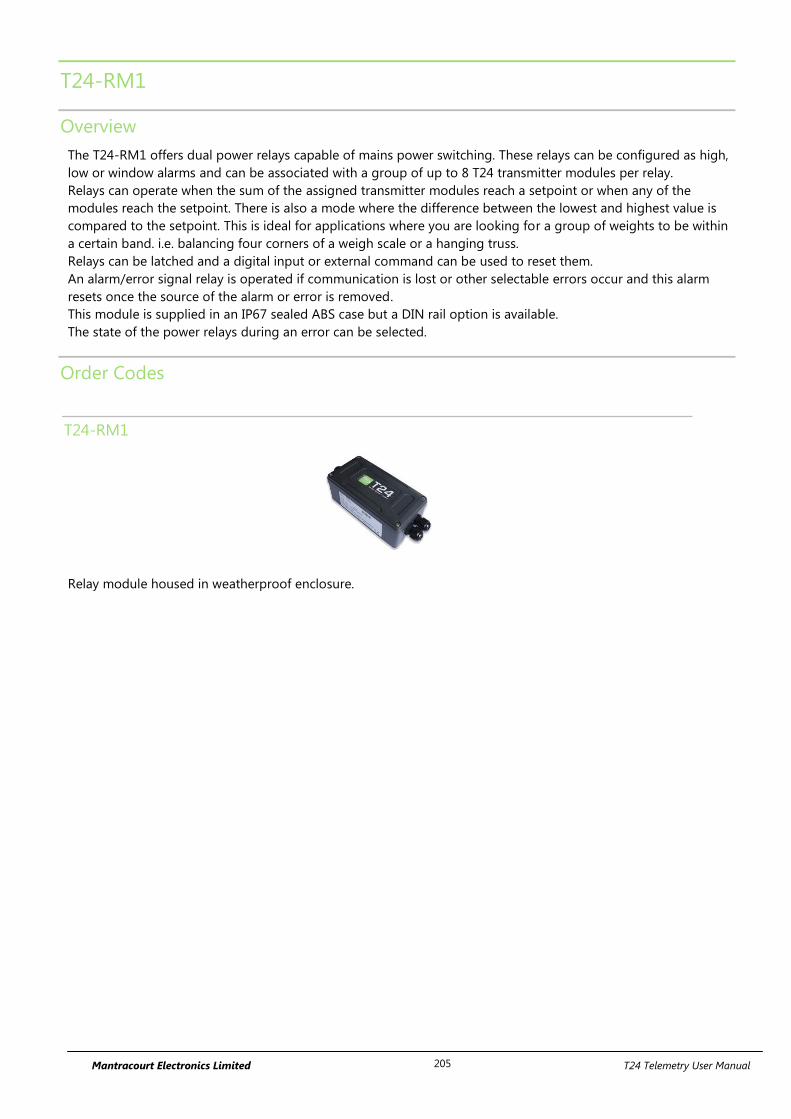
Mantracourt Electronics Limited T24 Telemetry User Manual 205
T24-RM1
Overview
The T24-RM1 offers dual power relays capable of mains power switching. These relays can be configured as high,
low or window alarms and can be associated with a group of up to 8 T24 transmitter modules per relay.
Relays can operate when the sum of the assigned transmitter modules reach a setpoint or when any of the
modules reach the setpoint. There is also a mode where the difference between the lowest and highest value is
compared to the setpoint. This is ideal for applications where you are looking for a group of weights to be within
a certain band. i.e. balancing four corners of a weigh scale or a hanging truss.
Relays can be latched and a digital input or external command can be used to reset them.
An alarm/error signal relay is operated if communication is lost or other selectable errors occur and this alarm
resets once the source of the alarm or error is removed.
This module is supplied in an IP67 sealed ABS case but a DIN rail option is available.
The state of the power relays during an error can be selected.
Order Codes
T24-RM1
Relay module housed in weatherproof enclosure.
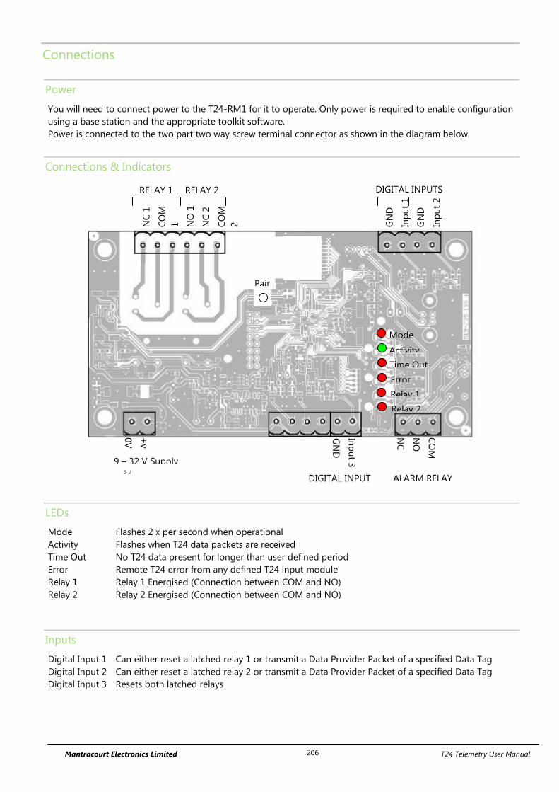
Mantracourt Electronics Limited T24 Telemetry User Manual 206
Connections
Power
You will need to connect power to the T24-RM1 for it to operate. Only power is required to enable configuration
using a base station and the appropriate toolkit software.
Power is connected to the two part two way screw terminal connector as shown in the diagram below.
Connections & Indicators
LEDs
Mode Flashes 2 x per second when operational
Activity Flashes when T24 data packets are received
Time Out No T24 data present for longer than user defined period
Error Remote T24 error from any defined T24 input module
Relay 1 Relay 1 Energised (Connection between COM and NO)
Relay 2 Relay 2 Energised (Connection between COM and NO)
Inputs
Digital Input 1 Can either reset a latched relay 1 or transmit a Data Provider Packet of a specified Data Tag
Digital Input 2 Can either reset a latched relay 2 or transmit a Data Provider Packet of a specified Data Tag
Digital Input 3 Resets both latched relays
RELAY 2
CO
M
NO
NC
GN
D
Inp
ut
1
GN
D
Inp
ut
2
NC
1
CO
M
1
NO
1
NC
2
CO
M
2
NO
2
+v
0V
RELAY 1
9 – 32 V Supply
+v
0V
ALARM RELAY
DIGITAL INPUTS
Inp
ut 3
GN
D
DIGITAL INPUT
Mode
Activity
Time Out
Error
Relay 1
Relay 2
Pair
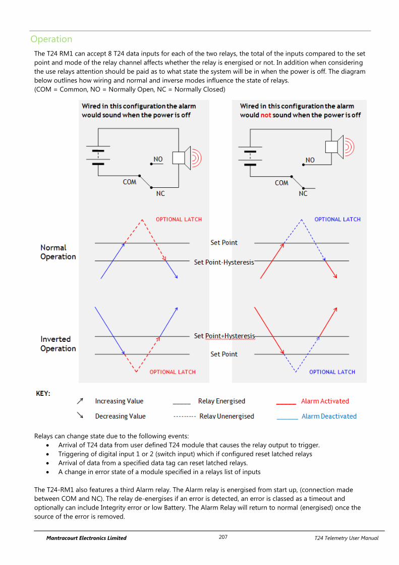
Mantracourt Electronics Limited T24 Telemetry User Manual 207
Operation
The T24 RM1 can accept 8 T24 data inputs for each of the two relays, the total of the inputs compared to the set
point and mode of the relay channel affects whether the relay is energised or not. In addition when considering
the use relays attention should be paid as to what state the system will be in when the power is off. The diagram
below outlines how wiring and normal and inverse modes influence the state of relays.
(COM = Common, NO = Normally Open, NC = Normally Closed)
Relays can change state due to the following events:
Arrival of T24 data from user defined T24 module that causes the relay output to trigger.
Triggering of digital input 1 or 2 (switch input) which if configured reset latched relays
Arrival of data from a specified data tag can reset latched relays.
A change in error state of a module specified in a relays list of inputs
The T24-RM1 also features a third Alarm relay. The Alarm relay is energised from start up, (connection made
between COM and NC). The relay de-energises if an error is detected, an error is classed as a timeout and
optionally can include Integrity error or low Battery. The Alarm Relay will return to normal (energised) once the
source of the error is removed.
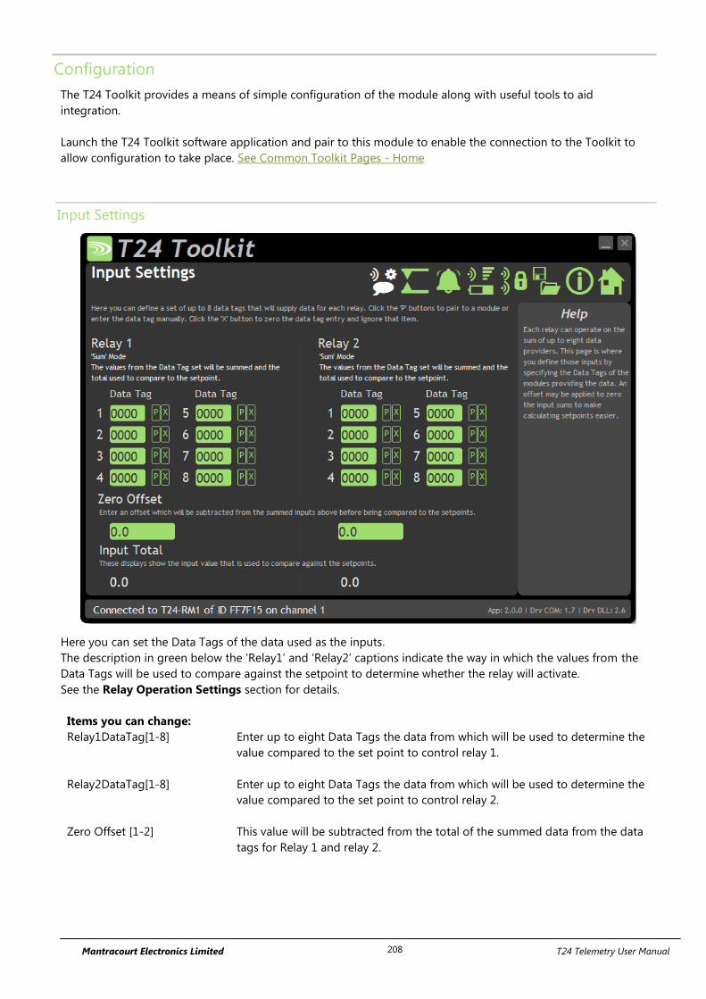
Mantracourt Electronics Limited T24 Telemetry User Manual 208
Configuration
The T24 Toolkit provides a means of simple configuration of the module along with useful tools to aid
integration.
Launch the T24 Toolkit software application and pair to this module to enable the connection to the Toolkit to
allow configuration to take place. See Common Toolkit Pages - Home
Input Settings
Here you can set the Data Tags of the data used as the inputs.
The description in green below the ‘Relay1’ and ‘Relay2’ captions indicate the way in which the values from the
Data Tags will be used to compare against the setpoint to determine whether the relay will activate.
See the Relay Operation Settings section for details.
Items you can change:
Relay1DataTag[1-8] Enter up to eight Data Tags the data from which will be used to determine the
value compared to the set point to control relay 1.
Relay2DataTag[1-8] Enter up to eight Data Tags the data from which will be used to determine the
value compared to the set point to control relay 2.
Zero Offset [1-2] This value will be subtracted from the total of the summed data from the data
tags for Relay 1 and relay 2.
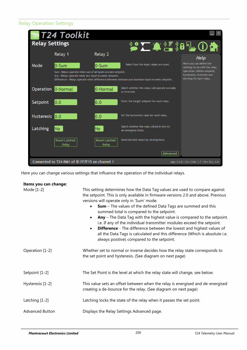
Mantracourt Electronics Limited T24 Telemetry User Manual 209
Relay Operation Settings
Here you can change various settings that influence the operation of the individual relays.
Items you can change:
Mode [1-2] This setting determines how the Data Tag values are used to compare against
the setpoint. This is only available in firmware versions 2.0 and above. Previous
versions will operate only in ‘Sum’ mode.
Sum – The values of the defined Data Tags are summed and this
summed total is compared to the setpoint.
Any – The Data Tag with the highest value is compared to the setpoint.
i.e. If any of the individual transmitter modules exceed the setpoint.
Difference - The difference between the lowest and highest values of
all the Data Tags is calculated and this difference (Which is absolute i.e.
always positive) compared to the setpoint.
Operation [1-2] Whether set to normal or inverse decides how the relay state corresponds to
the set point and hysteresis. (See diagram on next page)
Setpoint [1-2] The Set Point is the level at which the relay state will change, see below.
Hysteresis [1-2] This value sets an offset between when the relay is energised and de-energised
creating a de-bounce for the relay. (See diagram on next page)
Latching [1-2] Latching locks the state of the relay when it passes the set point.
Advanced Button Displays the Relay Settings Advanced page.

Mantracourt Electronics Limited T24 Telemetry User Manual 210
Operation and Hysteresis Settings
Relay de-energises when reaching the set point.
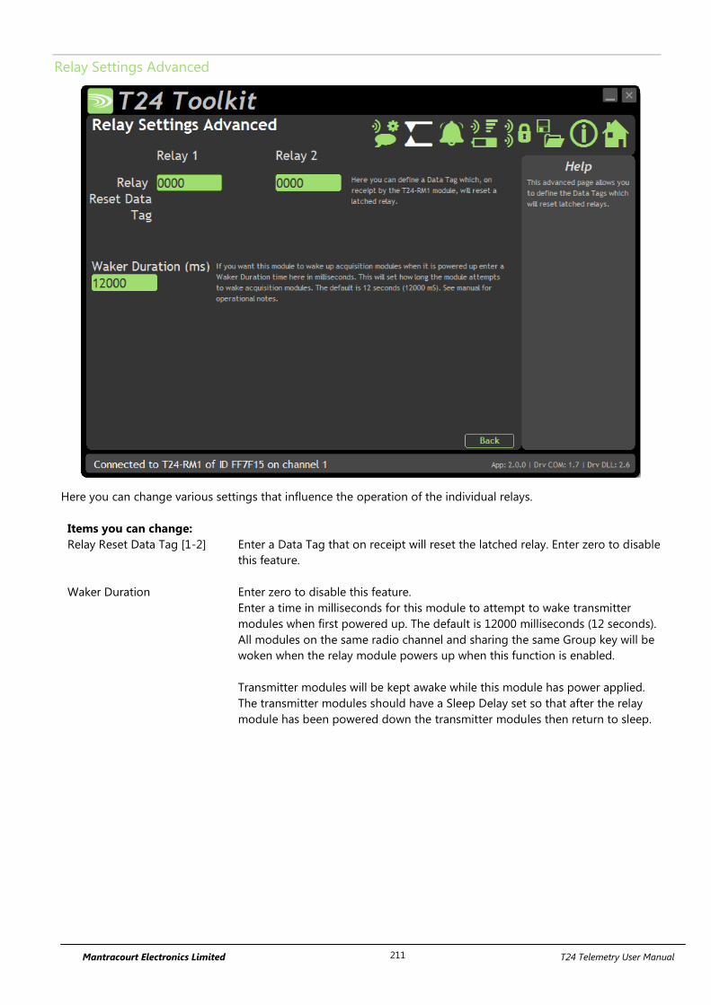
Mantracourt Electronics Limited T24 Telemetry User Manual 211
Relay Settings Advanced
Here you can change various settings that influence the operation of the individual relays.
Items you can change:
Relay Reset Data Tag [1-2] Enter a Data Tag that on receipt will reset the latched relay. Enter zero to disable
this feature.
Waker Duration Enter zero to disable this feature.
Enter a time in milliseconds for this module to attempt to wake transmitter
modules when first powered up. The default is 12000 milliseconds (12 seconds).
All modules on the same radio channel and sharing the same Group key will be
woken when the relay module powers up when this function is enabled.
Transmitter modules will be kept awake while this module has power applied.
The transmitter modules should have a Sleep Delay set so that after the relay
module has been powered down the transmitter modules then return to sleep.
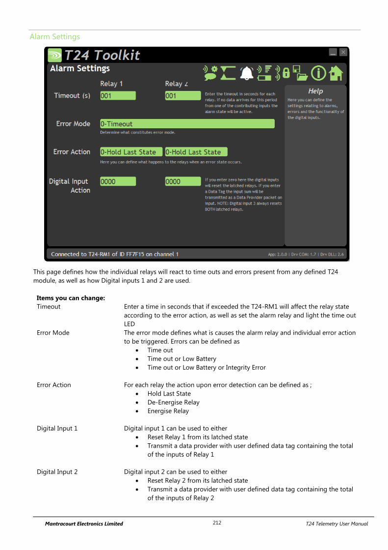
Mantracourt Electronics Limited T24 Telemetry User Manual 212
Alarm Settings
This page defines how the individual relays will react to time outs and errors present from any defined T24
module, as well as how Digital inputs 1 and 2 are used.
Items you can change:
Timeout Enter a time in seconds that if exceeded the T24-RM1 will affect the relay state
according to the error action, as well as set the alarm relay and light the time out
LED
Error Mode The error mode defines what is causes the alarm relay and individual error action
to be triggered. Errors can be defined as
Time out
Time out or Low Battery
Time out or Low Battery or Integrity Error
Error Action For each relay the action upon error detection can be defined as ;
Hold Last State
De-Energise Relay
Energise Relay
Digital Input 1 Digital input 1 can be used to either
Reset Relay 1 from its latched state
Transmit a data provider with user defined data tag containing the total
of the inputs of Relay 1
Digital Input 2 Digital input 2 can be used to either
Reset Relay 2 from its latched state
Transmit a data provider with user defined data tag containing the total
of the inputs of Relay 2

Mantracourt Electronics Limited T24 Telemetry User Manual 213
Enclosure & Mounting
This module is fitted inside our ACM ABS enclosure. Please see Appendix A – Enclosures & Mounting – ACM for
more information.
Antennas
These modules have the antenna already fitted inside the enclosure so there are no specific mounting
requirements.
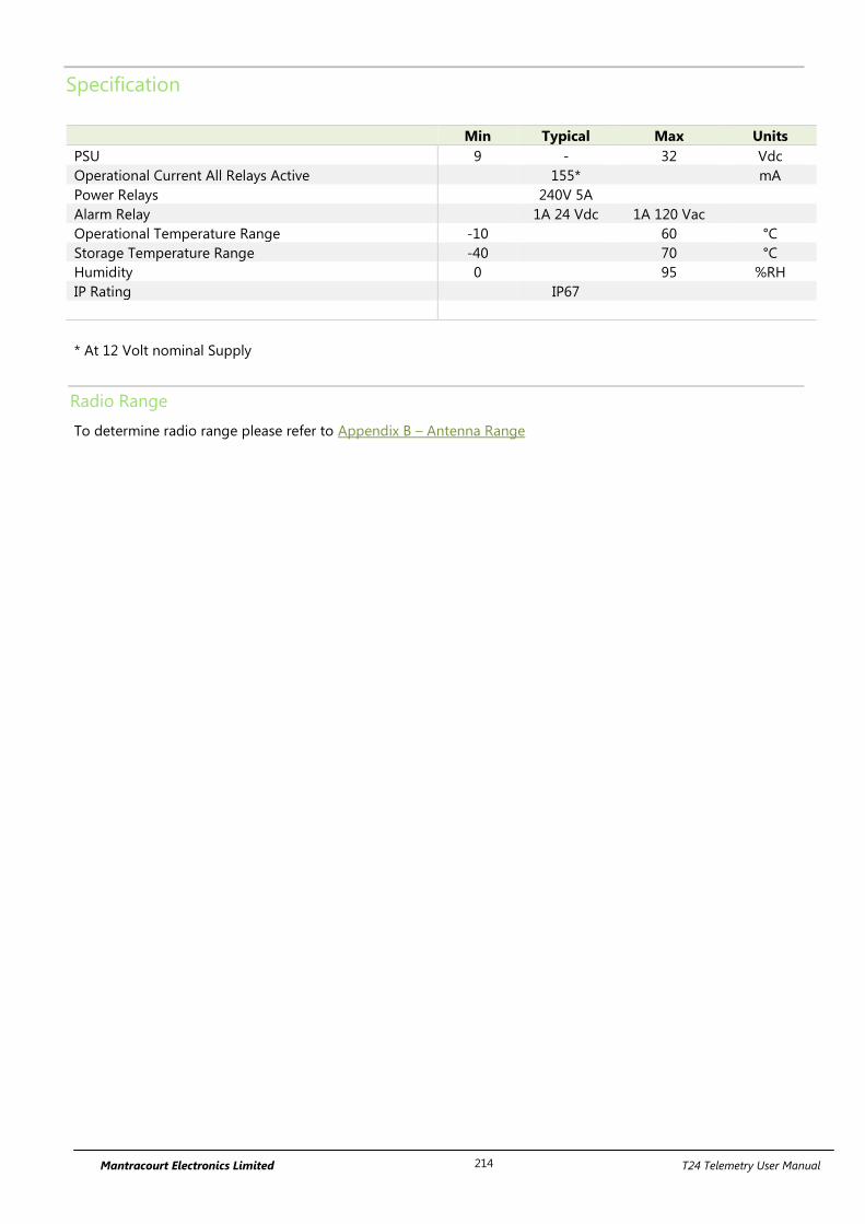
Mantracourt Electronics Limited T24 Telemetry User Manual 214
Specification
Min Typical Max Units
PSU 9 - 32 Vdc
Operational Current All Relays Active 155* mA
Power Relays 240V 5A
Alarm Relay 1A 24 Vdc 1A 120 Vac
Operational Temperature Range -10 60 °C
Storage Temperature Range -40 70 °C
Humidity 0 95 %RH
IP Rating IP67
* At 12 Volt nominal Supply
Radio Range
To determine radio range please refer to Appendix B – Antenna Range
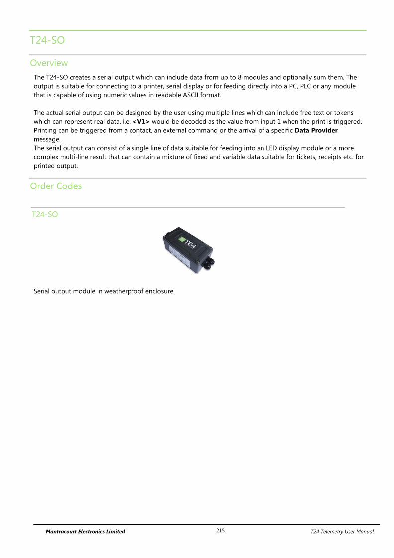
Mantracourt Electronics Limited T24 Telemetry User Manual 215
T24-SO
Overview
The T24-SO creates a serial output which can include data from up to 8 modules and optionally sum them. The
output is suitable for connecting to a printer, serial display or for feeding directly into a PC, PLC or any module
that is capable of using numeric values in readable ASCII format.
The actual serial output can be designed by the user using multiple lines which can include free text or tokens
which can represent real data. i.e. <V1> would be decoded as the value from input 1 when the print is triggered.
Printing can be triggered from a contact, an external command or the arrival of a specific Data Provider
message.
The serial output can consist of a single line of data suitable for feeding into an LED display module or a more
complex multi-line result that can contain a mixture of fixed and variable data suitable for tickets, receipts etc. for
printed output.
Order Codes
T24-SO
Serial output module in weatherproof enclosure.
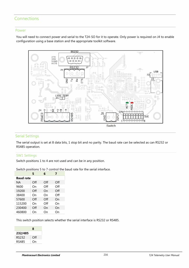
Mantracourt Electronics Limited T24 Telemetry User Manual 216
Connections
Power
You will need to connect power and serial to the T24-SO for it to operate. Only power is required on J4 to enable
configuration using a base station and the appropriate toolkit software.
1 8
ON
Switch
GN
D
INP
UTJ5
1
69
52 TX3 RX5 GND8 CTS
Serial Settings
The serial output is set at 8 data bits, 1 stop bit and no parity. The baud rate can be selected as can RS232 or
RS485 operation.
SW1 Settings
Switch positions 1 to 4 are not used and can be in any position.
Switch positions 5 to 7 control the baud rate for the serial interface.
This switch position selects whether the serial interface is RS232 or RS485.
8
232/485
RS232 Off
RS485 On
5 6 7
Baud rate
NA Off Off Off
9600 On Off Off
19200 Off On Off
38400 On On Off
57600 Off Off On
115200 On Off On
230400 Off On On
460800 On On On
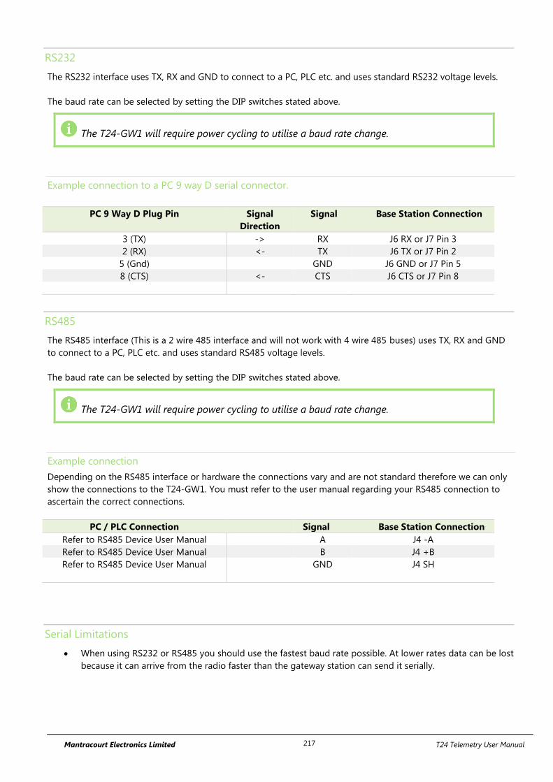
Mantracourt Electronics Limited T24 Telemetry User Manual 217
RS232
The RS232 interface uses TX, RX and GND to connect to a PC, PLC etc. and uses standard RS232 voltage levels.
The baud rate can be selected by setting the DIP switches stated above.
The T24-GW1 will require power cycling to utilise a baud rate change.
Example connection to a PC 9 way D serial connector.
PC 9 Way D Plug Pin Signal
Direction
Signal Base Station Connection
3 (TX) -> RX J6 RX or J7 Pin 3
2 (RX) <- TX J6 TX or J7 Pin 2
5 (Gnd) GND J6 GND or J7 Pin 5
8 (CTS) <- CTS J6 CTS or J7 Pin 8
RS485
The RS485 interface (This is a 2 wire 485 interface and will not work with 4 wire 485 buses) uses TX, RX and GND
to connect to a PC, PLC etc. and uses standard RS485 voltage levels.
The baud rate can be selected by setting the DIP switches stated above.
The T24-GW1 will require power cycling to utilise a baud rate change.
Example connection
Depending on the RS485 interface or hardware the connections vary and are not standard therefore we can only
show the connections to the T24-GW1. You must refer to the user manual regarding your RS485 connection to
ascertain the correct connections.
PC / PLC Connection Signal Base Station Connection
Refer to RS485 Device User Manual A J4 -A
Refer to RS485 Device User Manual B J4 +B
Refer to RS485 Device User Manual GND J4 SH
Serial Limitations
When using RS232 or RS485 you should use the fastest baud rate possible. At lower rates data can be lost
because it can arrive from the radio faster than the gateway station can send it serially.
Mantracourt Electronics Limited T24 Telemetry User Manual 218
Configuration
Once it has been determined how many modules are feeding data to this module you need to record the Data
Tag that each of these modules are attaching to their Data Provider packets.
These Data Tags are then entered into the ValueDataTagx parameters. Once the rate at which this data arrives is
known you can enter the Timeoutx values.
Leave unused ValueDataTagx parameters with a value of zero to ensure that they are not checked for timeouts
and do not contribute to gross or net sums.
When a data provider packet arrives whose Data Tag matches one of those in the ValueDataTagx parameters the
value it contains will be placed in the Valuex parameter.
If data does not arrive from a module within the Timeoutx period then any reference to either the individual Vx
tokens or one of the summing tokens will result in ------ rather than a numeric value.
The actual serial output can now be constructed using Line1 to Line25. These parameters take text into which
you can insert tokens. When a 'Print' is generated these lines are parsed and tokens replaced with the values they
represent and the resulting data sent to the serial port.
A 'Print' is generated by either activating the switch input when SwitchMode is set to zero or by receiving a Data
Provider packet whose Data Tag matches the PrintDataTag parameter.
When a 'Print' is executed each of the parameters Line1 to Line 25 will be parsed. Every token will be evaluated
and replaced with the live value.
Getting Started
To associate transmitter modules with the T24-SO you must first ensure that the appropriate modules are
transmitting their values at a suitable rate such as the default of 3 per second. Then you can configure the T24-SO
module to use the data from these transmitters.
Configuration must be done with the T24 Toolkit software and a base station.
Serial output is triggered by one of the following:
The digital input (switch input) which may trigger an output/print or tare the summed value.
Arrival of a data packet identified with a Data Tag that matches what the T24-SO uses to trigger an
output/print.
Arrival of a command to trigger an output/print or to tare or zero etc.
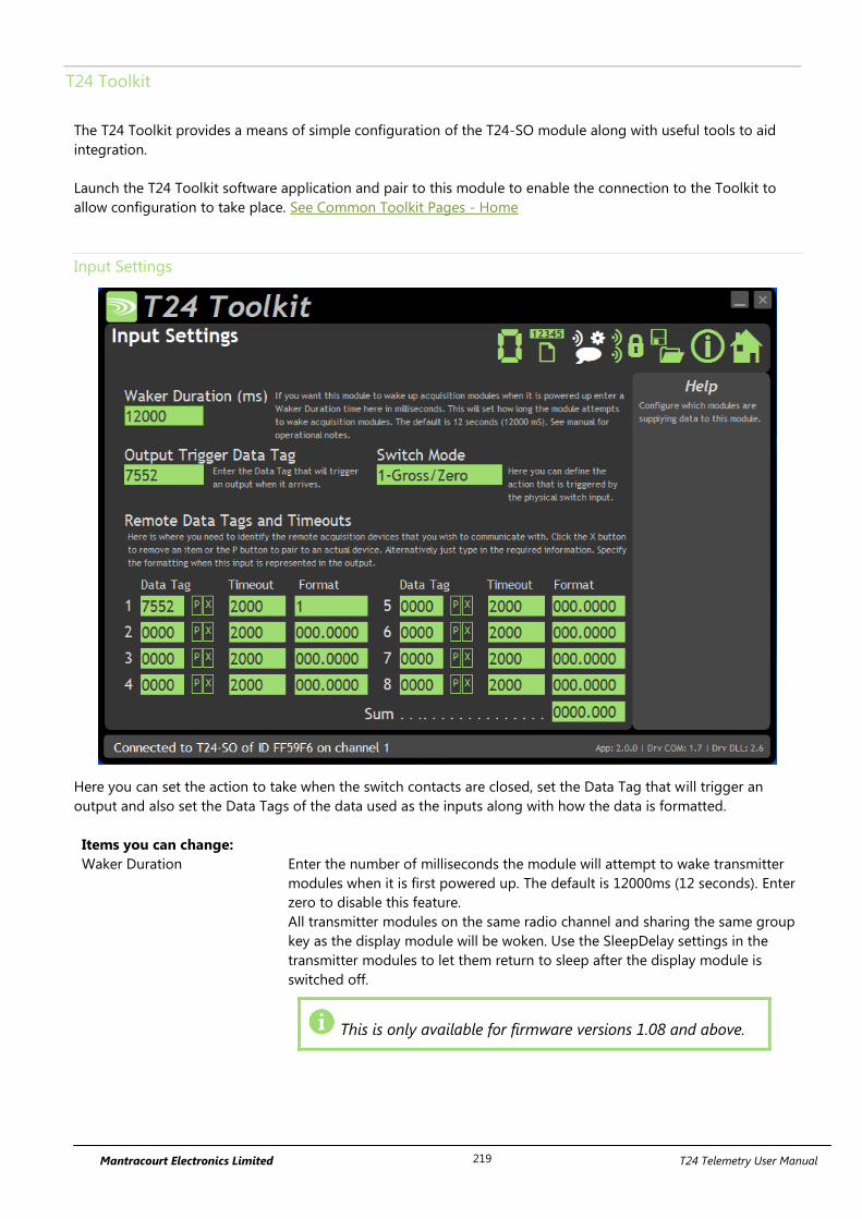
Mantracourt Electronics Limited T24 Telemetry User Manual 219
T24 Toolkit
The T24 Toolkit provides a means of simple configuration of the T24-SO module along with useful tools to aid
integration.
Launch the T24 Toolkit software application and pair to this module to enable the connection to the Toolkit to
allow configuration to take place. See Common Toolkit Pages - Home
Input Settings
Here you can set the action to take when the switch contacts are closed, set the Data Tag that will trigger an
output and also set the Data Tags of the data used as the inputs along with how the data is formatted.
Items you can change:
Waker Duration Enter the number of milliseconds the module will attempt to wake transmitter
modules when it is first powered up. The default is 12000ms (12 seconds). Enter
zero to disable this feature.
All transmitter modules on the same radio channel and sharing the same group
key as the display module will be woken. Use the SleepDelay settings in the
transmitter modules to let them return to sleep after the display module is
switched off.
This is only available for firmware versions 1.08 and above.
Mantracourt Electronics Limited T24 Telemetry User Manual 220
Output Trigger Data Tag Enter the Data Tag which, on arrival, will trigger an output (i.e. print). Note that
Min Interval setting on the Output Settings page may stop this from working
at the rate at which the data arrives.
This is usually set to the Data Tag of one of the inputs.
Example: If the output was being sent to a serial display the same Data Tag
would be assigned to input 1 and the output trigger so that each time data
arrived the output would be sent to the serial display.
Switch Mode Action to perform when switch contacts on J5 are closed. Click to select either:
Print – Triggers an output from the serial port. Note that Min Interval setting
on the Output Settings page may stop this from working at the rate the contact
closes.
Gross/Zero – Toggles the measurement mode between gross and net. When
switching to net the net value is zeroed (tared). This will affect the value of the
<N> token which is the net value of all summed inputs.
Remote data Tags and Timeouts
Data Tag Enter the Data Tag (in hexadecimal) to supply data to this input.
You can click the ‘P’ button to retrieve the Data Tag of a
module by pairing to it which is usually initiated by power
cycling the module.
Clicking the ‘X’ button zeroes the entered Data Tag.
Timeout Enter the timeout in milliseconds for this input. If a new Data Provider packet
does not arrive within this time and reference to this input value (via token
<V1> for example) will result in an output of -------. This also applies to a gross
or net reading derived from this input.
Format Describe the format that this value is to take when output. You specify integer
digits and decimal places by entering a format consisting of zeroes and decimal
points. i.e. 00.000
The integer value of data takes precedence over your defined
format so if you defined a format of 0.0 and data of value
100.8265 arrived it would be represented as 100.8
Examples
Format Value Representation
0.0 1.2 1.2
0.0 100.8 100.8
00.000 6.1234 06.123
00.000 123.4567 123.456
0000.00 12.0 0012.00
Resolution
It is possible to set the resolution (the smallest unit of change) of the output
results by including the numeric value in the format. i.e.
00.005 would only represent the value in steps of 00.005
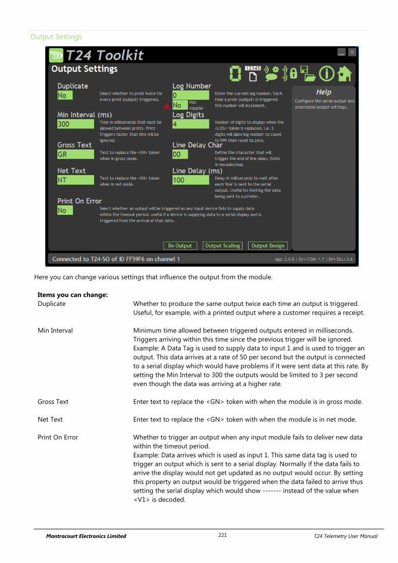
Mantracourt Electronics Limited T24 Telemetry User Manual 221
Output Settings
Here you can change various settings that influence the output from the module.
Items you can change:
Duplicate Whether to produce the same output twice each time an output is triggered.
Useful, for example, with a printed output where a customer requires a receipt.
Min Interval Minimum time allowed between triggered outputs entered in milliseconds.
Triggers arriving within this time since the previous trigger will be ignored.
Example: A Data Tag is used to supply data to input 1 and is used to trigger an
output. This data arrives at a rate of 50 per second but the output is connected
to a serial display which would have problems if it were sent data at this rate. By
setting the Min Interval to 300 the outputs would be limited to 3 per second
even though the data was arriving at a higher rate.
Gross Text Enter text to replace the <GN> token with when the module is in gross mode.
Net Text Enter text to replace the <GN> token with when the module is in net mode.
Print On Error Whether to trigger an output when any input module fails to deliver new data
within the timeout period.
Example: Data arrives which is used as input 1. This same data tag is used to
trigger an output which is sent to a serial display. Normally if the data fails to
arrive the display would not get updated as no output would occur. By setting
this property an output would be triggered when the data failed to arrive thus
setting the serial display which would show ------- instead of the value when
<V1> is decoded.
Mantracourt Electronics Limited T24 Telemetry User Manual 222
Log Number Enter a log number that is used when the <LOG> token is decoded. Each time
an output is triggered this log number is incremented. This number will wrap to
zero once it reaches the maximum value displayable due to the Log Digits.
Log Number (Non Volatile) The Log number defaults to being volatile. Power cycling the T24-SO will revert
the log number to the value seen on this page. This is ideal for when you have a
fast output and you want the outputs to be numbered sequentially. i.e. with a
fast output being sent to a data logger.
Sometime it is required that the log number is Non Volatile, that is, the log
number is restored each time the T24-SO is power cycled.
This is useful when the output is used to drive a printer, for example, and the
log number acts as a unique number on the customer ticket.
When set to Yes the module must store the new Log Number each time it is
incremented. This takes time and also uses up the finite write cycles of the
internal flash memory. Therefore it is recommended that turning on the Non
Volatile option is only done when the output (containing a <LOG> token) is
triggered at 30 second intervals or less.
Log Digits Set the number of digits to display when the <LOG> token is decoded.
Example: If this is set to 2 then the log number will count up to 99 before
resetting.
Line Delay Char As the serial output has no hardware handshaking it is sometimes necessary to
limit the rate at which the output is sent. This is most apparent with multiline
outputs to a printer.
Example: A printer requires a 0x0A (decimal 10) character (linefeed) to be sent at
the end of each line to cause the printer to actually print the line.
This character would be embedded in the actual designed output and the Line
Delay Char set to 0A so each time a line is sent to the printer a delay occurs
before the next part of the output is initiated. The delay is set by Line Delay.
Line Delay The delay in milliseconds that occurs when the Line Delay Character has been
sent to the output.
Buttons
Do Output Trigger the output when clicked.
Output Scaling Will display the Output Scaling page.
Output Design Will display the Output Design page. This is where you define the output data.
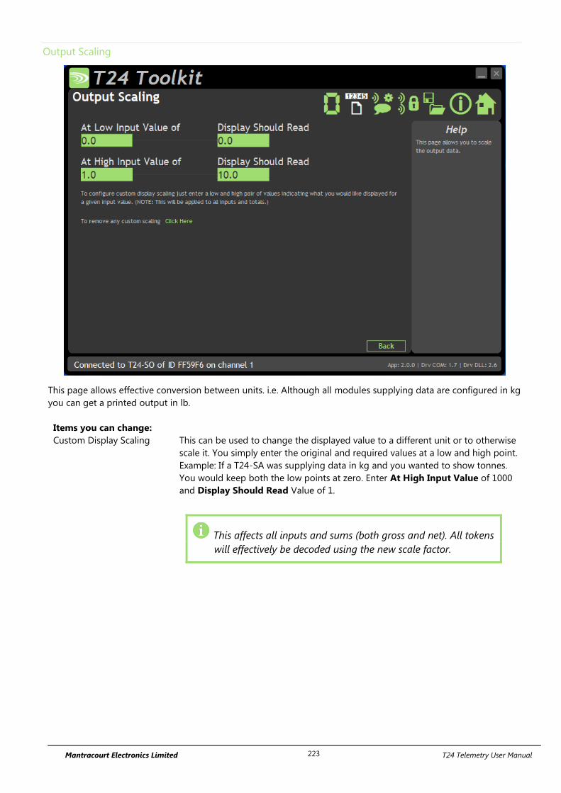
Mantracourt Electronics Limited T24 Telemetry User Manual 223
Output Scaling
This page allows effective conversion between units. i.e. Although all modules supplying data are configured in kg
you can get a printed output in lb.
Items you can change:
Custom Display Scaling This can be used to change the displayed value to a different unit or to otherwise
scale it. You simply enter the original and required values at a low and high point.
Example: If a T24-SA was supplying data in kg and you wanted to show tonnes.
You would keep both the low points at zero. Enter At High Input Value of 1000
and Display Should Read Value of 1.
This affects all inputs and sums (both gross and net). All tokens
will effectively be decoded using the new scale factor.
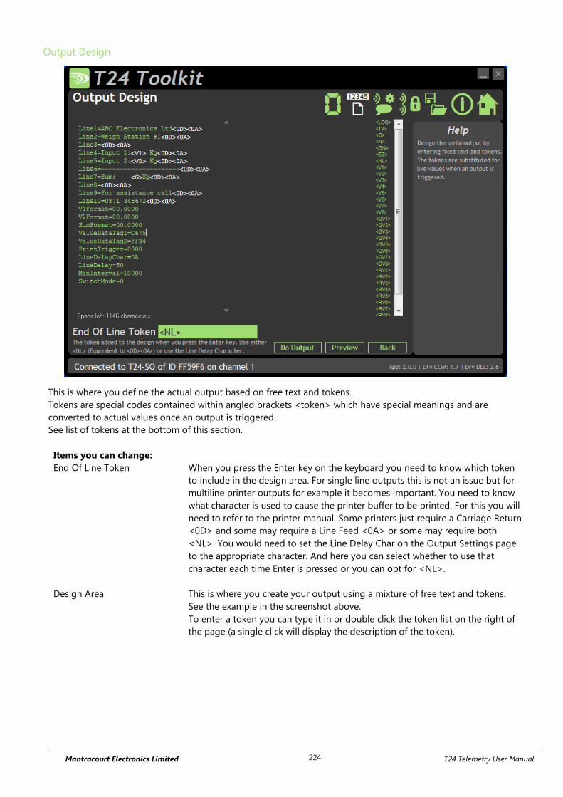
Mantracourt Electronics Limited T24 Telemetry User Manual 224
Output Design
This is where you define the actual output based on free text and tokens.
Tokens are special codes contained within angled brackets <token> which have special meanings and are
converted to actual values once an output is triggered.
See list of tokens at the bottom of this section.
Items you can change:
End Of Line Token When you press the Enter key on the keyboard you need to know which token
to include in the design area. For single line outputs this is not an issue but for
multiline printer outputs for example it becomes important. You need to know
what character is used to cause the printer buffer to be printed. For this you will
need to refer to the printer manual. Some printers just require a Carriage Return
<0D> and some may require a Line Feed <0A> or some may require both
<NL>. You would need to set the Line Delay Char on the Output Settings page
to the appropriate character. And here you can select whether to use that
character each time Enter is pressed or you can opt for <NL>.
Design Area This is where you create your output using a mixture of free text and tokens.
See the example in the screenshot above.
To enter a token you can type it in or double click the token list on the right of
the page (a single click will display the description of the token).
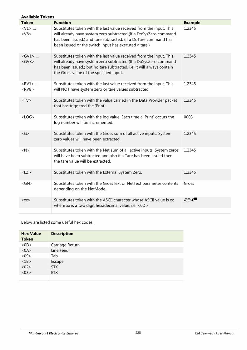
Mantracourt Electronics Limited T24 Telemetry User Manual 225
Available Tokens
Token Function Example
<V1> …
<V8>
Substitutes token with the last value received from the input. This
will already have system zero subtracted (If a DoSysZero command
has been issued.) and tare subtracted. (If a DoTare command has
been issued or the switch input has executed a tare.)
1.2345
<GV1> …
<GV8>
Substitutes token with the last value received from the input. This
will already have system zero subtracted (If a DoSysZero command
has been issued.) but no tare subtracted. i.e. it will always contain
the Gross value of the specified input.
1.2345
<RV1> …
<RV8>
Substitutes token with the last value received from the input. This
will NOT have system zero or tare values subtracted.
1.2345
<TV> Substitutes token with the value carried in the Data Provider packet
that has triggered the 'Print'.
1.2345
<LOG> Substitutes token with the log value. Each time a 'Print' occurs the
log number will be incremented.
0003
<G> Substitutes token with the Gross sum of all active inputs. System
zero values will have been extracted.
1.2345
<N> Substitutes token with the Net sum of all active inputs. System zeros
will have been subtracted and also if a Tare has been issued then
the tare value will be extracted.
1.2345
<EZ> Substitutes token with the External System Zero.
1.2345
<GN> Substitutes token with the GrossText or NetText parameter contents
depending on the NetMode.
Gross
<xx> Substitutes token with the ASCII character whose ASCII value is xx
where xx is a two digit hexadecimal value. i.e. <0D>
ÆӪ-ü▀
Below are listed some useful hex codes.
Hex Value
Token
Description
<0D> Carriage Return
<0A> Line Feed
<09> Tab
<1B> Escape
<02> STX
<03> ETX
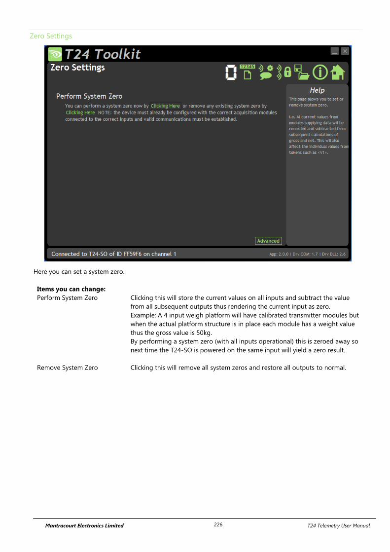
Mantracourt Electronics Limited T24 Telemetry User Manual 226
Zero Settings
Here you can set a system zero.
Items you can change:
Perform System Zero Clicking this will store the current values on all inputs and subtract the value
from all subsequent outputs thus rendering the current input as zero.
Example: A 4 input weigh platform will have calibrated transmitter modules but
when the actual platform structure is in place each module has a weight value
thus the gross value is 50kg.
By performing a system zero (with all inputs operational) this is zeroed away so
next time the T24-SO is powered on the same input will yield a zero result.
Remove System Zero Clicking this will remove all system zeros and restore all outputs to normal.

Mantracourt Electronics Limited T24 Telemetry User Manual 227
Zero Settings Advanced
This advanced section allows the use of a specially configured external module to supply the system zero value
for the handheld to use.
Example:
The same T24-SO is used with a truck that picks up different trailers and is required to display the sum of 4 strain
gauges connected to each trailer (Using T24-SAs).
Because each trailer will have a different system zero requirement you would add a further module to each trailer
set to transmit the system zero value. It is the Data Tag that is entered here.
On all trailers the transmitter module sets would share the same Data Tags.
Items you can change:
Data Tag Enter the Data Tag of the message to use for the external system zero.
ID Contains the ID of the module used to supply the external system zero. This is only necessary to
provide a visible record of the remote module and is shown to keep compatibility with the Mode
and Communications page.
You do not need to enter anything here although it will be filled in automatically if you perform a
pair to retrieve data.
P Click this to give 5 seconds to perform pairing to automatically provide the Data Tag and ID from a
specific module. Usually pairing is activated by removing and replacing the power supply.
X Click this to reset the Data Tag and ID to zero (disabling the external system zero function).
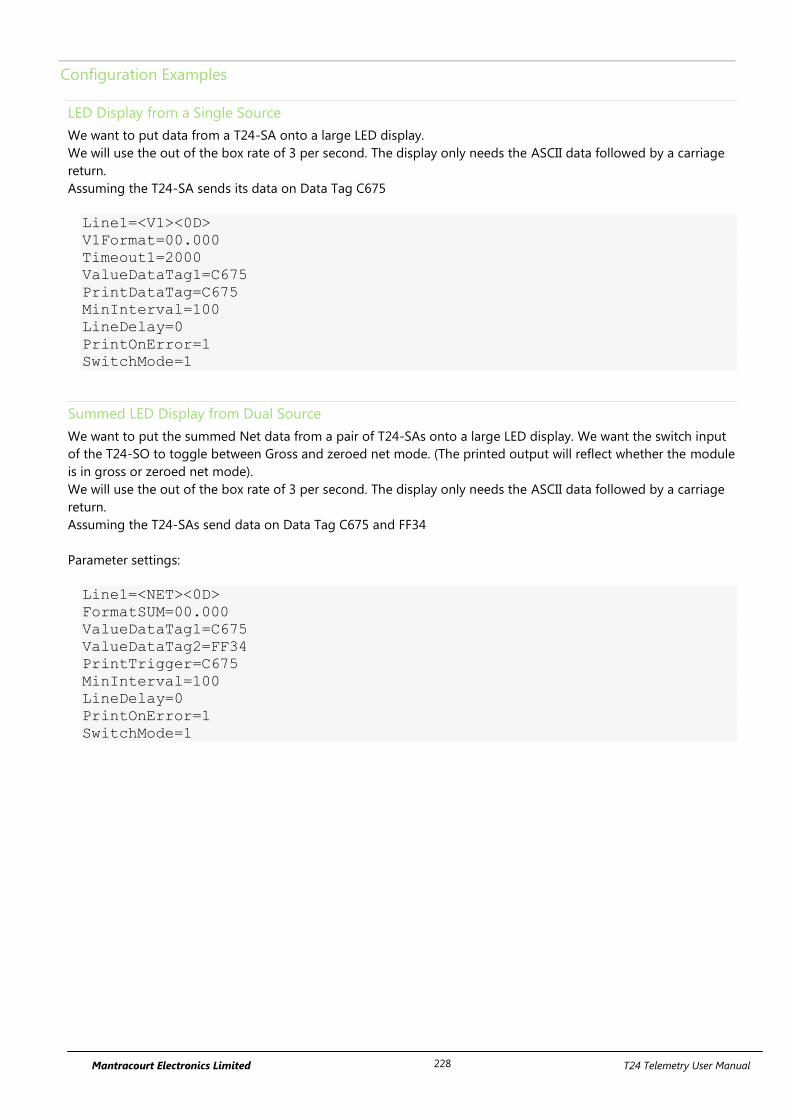
Mantracourt Electronics Limited T24 Telemetry User Manual 228
Configuration Examples
LED Display from a Single Source
We want to put data from a T24-SA onto a large LED display.
We will use the out of the box rate of 3 per second. The display only needs the ASCII data followed by a carriage
return.
Assuming the T24-SA sends its data on Data Tag C675
Line1=<V1><0D>
V1Format=00.000
Timeout1=2000
ValueDataTag1=C675
PrintDataTag=C675
MinInterval=100
LineDelay=0
PrintOnError=1
SwitchMode=1
Summed LED Display from Dual Source
We want to put the summed Net data from a pair of T24-SAs onto a large LED display. We want the switch input
of the T24-SO to toggle between Gross and zeroed net mode. (The printed output will reflect whether the module
is in gross or zeroed net mode).
We will use the out of the box rate of 3 per second. The display only needs the ASCII data followed by a carriage
return.
Assuming the T24-SAs send data on Data Tag C675 and FF34
Parameter settings:
Line1=<NET><0D>
FormatSUM=00.000
ValueDataTag1=C675
ValueDataTag2=FF34
PrintTrigger=C675
MinInterval=100
LineDelay=0
PrintOnError=1
SwitchMode=1
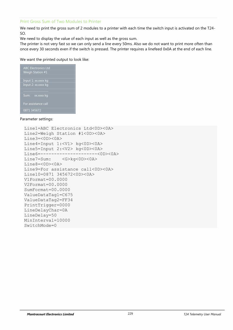
Mantracourt Electronics Limited T24 Telemetry User Manual 229
Print Gross Sum of Two Modules to Printer
We need to print the gross sum of 2 modules to a printer with each time the switch input is activated on the T24-
SO.
We need to display the value of each input as well as the gross sum.
The printer is not very fast so we can only send a line every 50ms. Also we do not want to print more often than
once every 30 seconds even if the switch is pressed. The printer requires a linefeed 0x0A at the end of each line.
We want the printed output to look like:
ABC Electronics Ltd
Weigh Station #1
Input 1: xx.xxxx kg
Input 2: xx.xxxx kg
--------------------
Sum: xx.xxxx kg
For assistance call
0871 345672
Parameter settings:
Line1=ABC Electronics Ltd<0D><0A>
Line2=Weigh Station #1<0D><0A>
Line3=<0D><0A>
Line4=Input 1:<V1> kg<0D><0A>
Line5=Input 2:<V2> kg<0D><0A>
Line6=---------------------<0D><0A>
Line7=Sum: <G>kg<0D><0A>
Line8=<0D><0A>
Line9=For assistance call<0D><0A>
Line10=0871 345672<0D><0A>
V1Format=00.0000
V2Format=00.0000
SumFormat=00.0000
ValueDataTag1=C675
ValueDataTag2=FF34
PrintTrigger=0000
LineDelayChar=0A
LineDelay=50
MinInterval=10000
SwitchMode=0
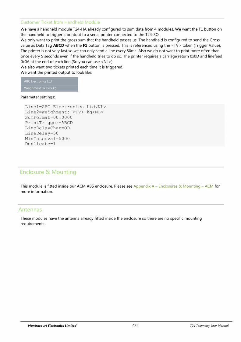
Mantracourt Electronics Limited T24 Telemetry User Manual 230
Customer Ticket from Handheld Module
We have a handheld module T24-HA already configured to sum data from 4 modules. We want the F1 button on
the handheld to trigger a printout to a serial printer connected to the T24-SO.
We only want to print the gross sum that the handheld passes us. The handheld is configured to send the Gross
value as Data Tag ABCD when the F1 button is pressed. This is referenced using the <TV> token (Trigger Value).
The printer is not very fast so we can only send a line every 50ms. Also we do not want to print more often than
once every 5 seconds even if the handheld tries to do so. The printer requires a carriage return 0x0D and linefeed
0x0A at the end of each line (So you can use <NL>).
We also want two tickets printed each time it is triggered.
We want the printed output to look like:
ABC Electronics Ltd
Weighment: xx.xxxx kg
Parameter settings:
Line1=ABC Electronics Ltd<NL>
Line2=Weighment: <TV> kg<NL>
SumFormat=00.0000
PrintTrigger=ABCD
LineDelayChar=OD
LineDelay=50
MinInterval=5000
Duplicate=1
Enclosure & Mounting
This module is fitted inside our ACM ABS enclosure. Please see Appendix A – Enclosures & Mounting – ACM for
more information.
Antennas
These modules have the antenna already fitted inside the enclosure so there are no specific mounting
requirements.
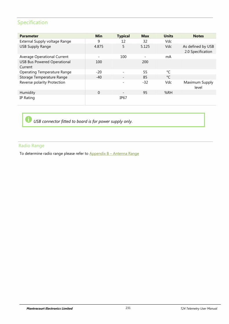
Mantracourt Electronics Limited T24 Telemetry User Manual 231
Specification
Parameter Min Typical Max Units Notes
External Supply voltage Range 9 12 32 Vdc
USB Supply Range 4.875 5 5.125 Vdc As defined by USB
2.0 Specification
Average Operational Current - 100 - mA
USB Bus Powered Operational
Current
100 200
Operating Temperature Range -20 - 55 °C
Storage Temperature Range -40 - 85 °C
Reverse polarity Protection - -32 Vdc Maximum Supply
level
Humidity 0 - 95 %RH
IP Rating IP67
USB connector fitted to board is for power supply only.
Radio Range
To determine radio range please refer to Appendix B – Antenna Range
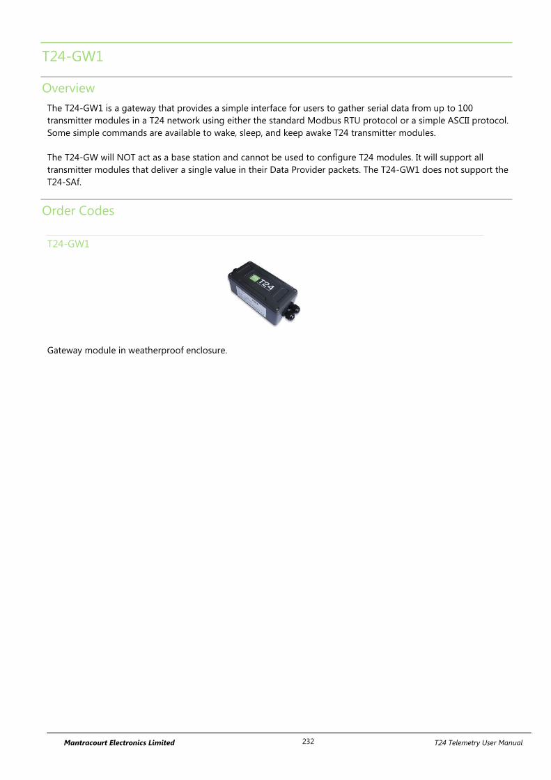
Mantracourt Electronics Limited T24 Telemetry User Manual 232
T24-GW1
Overview
The T24-GW1 is a gateway that provides a simple interface for users to gather serial data from up to 100
transmitter modules in a T24 network using either the standard Modbus RTU protocol or a simple ASCII protocol.
Some simple commands are available to wake, sleep, and keep awake T24 transmitter modules.
The T24-GW will NOT act as a base station and cannot be used to configure T24 modules. It will support all
transmitter modules that deliver a single value in their Data Provider packets. The T24-GW1 does not support the
T24-SAf.
Order Codes
T24-GW1
Gateway module in weatherproof enclosure.
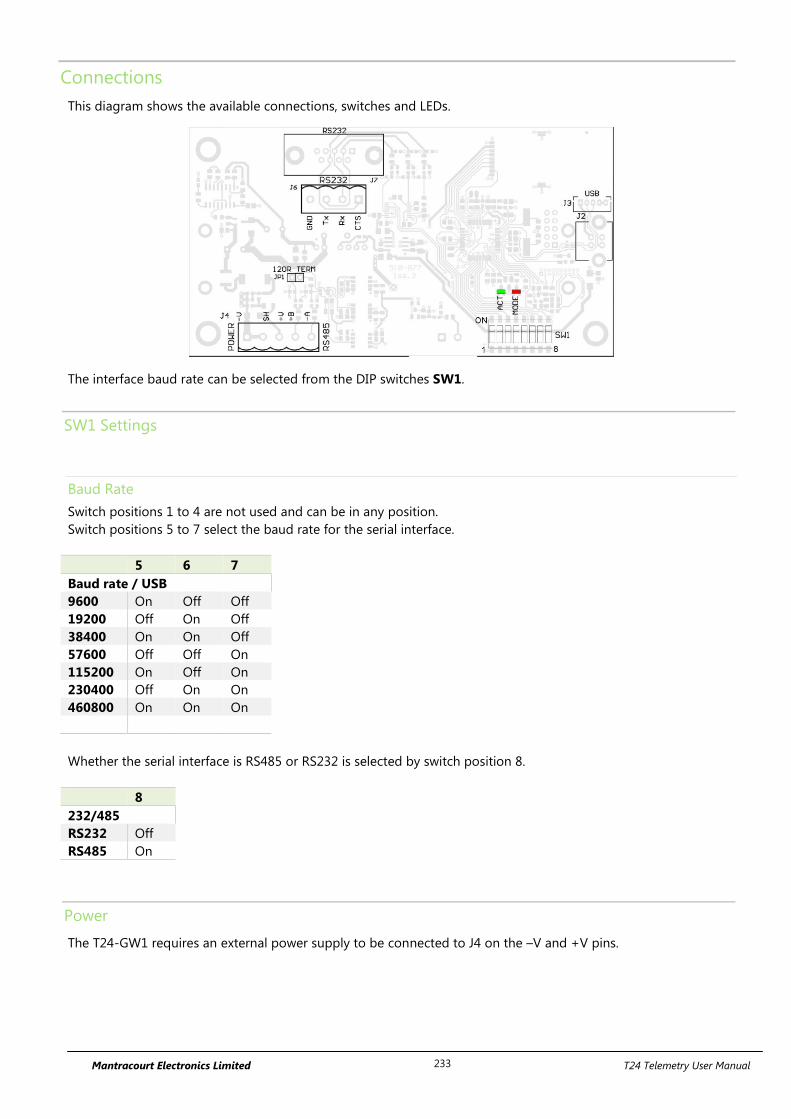
Mantracourt Electronics Limited T24 Telemetry User Manual 233
Connections
This diagram shows the available connections, switches and LEDs.
1 8
ON
The interface baud rate can be selected from the DIP switches SW1.
SW1 Settings
Baud Rate
Switch positions 1 to 4 are not used and can be in any position.
Switch positions 5 to 7 select the baud rate for the serial interface.
5 6 7
Baud rate / USB
9600 On Off Off
19200 Off On Off
38400 On On Off
57600 Off Off On
115200 On Off On
230400 Off On On
460800 On On On
Whether the serial interface is RS485 or RS232 is selected by switch position 8.
8
232/485
RS232 Off
RS485 On
Power
The T24-GW1 requires an external power supply to be connected to J4 on the –V and +V pins.
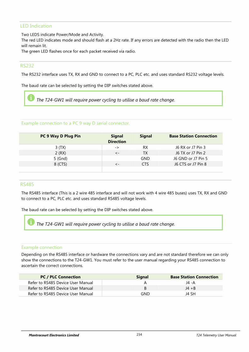
Mantracourt Electronics Limited T24 Telemetry User Manual 234
LED Indication
Two LEDS indicate Power/Mode and Activity.
The red LED indicates mode and should flash at a 2Hz rate. If any errors are detected with the radio then the LED
will remain lit.
The green LED flashes once for each packet received via radio.
RS232
The RS232 interface uses TX, RX and GND to connect to a PC, PLC etc. and uses standard RS232 voltage levels.
The baud rate can be selected by setting the DIP switches stated above.
The T24-GW1 will require power cycling to utilise a baud rate change.
Example connection to a PC 9 way D serial connector.
PC 9 Way D Plug Pin Signal
Direction
Signal Base Station Connection
3 (TX) -> RX J6 RX or J7 Pin 3
2 (RX) <- TX J6 TX or J7 Pin 2
5 (Gnd) GND J6 GND or J7 Pin 5
8 (CTS) <- CTS J6 CTS or J7 Pin 8
RS485
The RS485 interface (This is a 2 wire 485 interface and will not work with 4 wire 485 buses) uses TX, RX and GND
to connect to a PC, PLC etc. and uses standard RS485 voltage levels.
The baud rate can be selected by setting the DIP switches stated above.
The T24-GW1 will require power cycling to utilise a baud rate change.
Example connection
Depending on the RS485 interface or hardware the connections vary and are not standard therefore we can only
show the connections to the T24-GW1. You must refer to the user manual regarding your RS485 connection to
ascertain the correct connections.
PC / PLC Connection Signal Base Station Connection
Refer to RS485 Device User Manual A J4 -A
Refer to RS485 Device User Manual B J4 +B
Refer to RS485 Device User Manual GND J4 SH

Mantracourt Electronics Limited T24 Telemetry User Manual 235
Serial Limitations
When using RS232 or RS485 you should use the fastest baud rate possible. At lower rates data can be lost
because it can arrive from the radio faster than the gateway station can send it serially.
Mantracourt Electronics Limited T24 Telemetry User Manual 236
Communications Overview
MODBUS Communication
The T24-GW1 operates on Modbus RTU communication 8,N 1 ( 8 data bits, No Parity, 1 stop bit). The following
Modbus Function codes are supported
Function 03 ‘Read Holding Registers’
Function 06 ‘Write Single Register’
Function 16 ‘Write Multiple Registers’
The gateway has a single modbus address, 1 is the default address but this can be changed via register 41001 or
via the T24-Toolkit.
Control Registers
41001 – Read / Write
Set the MODBUS slave module ID, module ID will be 1 as default. Valid values 0-255.
41004 – Read / Write
Set to the T24 RF channel the gateway is working on. Valid values 1-15.
41005 – Read / Write
Set to the number of cells to be programmed into the table of data tags default = 0. Valid values 0-100
41006 – Read / Write
Set the Time out Value (seconds), if a channel does not update with in the timeout time the value register will be
set to either the default value or last value received, see Toolkit – General Settings. Valid values 0-255.
41007 – Read / Write
Set the Sleep time (seconds), this is the period for which the gateway will sleep any module it sees after the
broadcast sleep register (41002) has been set to 1. The T24-GW1 will only sleep modules listed in the Data Tag
registers. Valid Values 0-255.
41008 – Read / Write
This register Enables or disables the functionality to keep awake the modules specified in Data Tag Registers.
Valid values 0 or 1.
Commands
Writing a 1 to the following registers will execute the following commands:
41002 – Read / Write
Set to 1 to perform broadcast sleep to all modules, it will set back to zero when the sleep timer value has been
reached.
41003 – Read / Write
Set to 1 to perform broadcast wake to all modules, it will set back to zero when the waker duration has been
reached, the default waker duration is 12 seconds but can be set using the T24-Toolkit, see Toolkit – General
Settings.
41009 – Read / Write
Set to 1 to perform module save to save all the current settings and data tags in the module. It will set back to
zero once the save is complete.
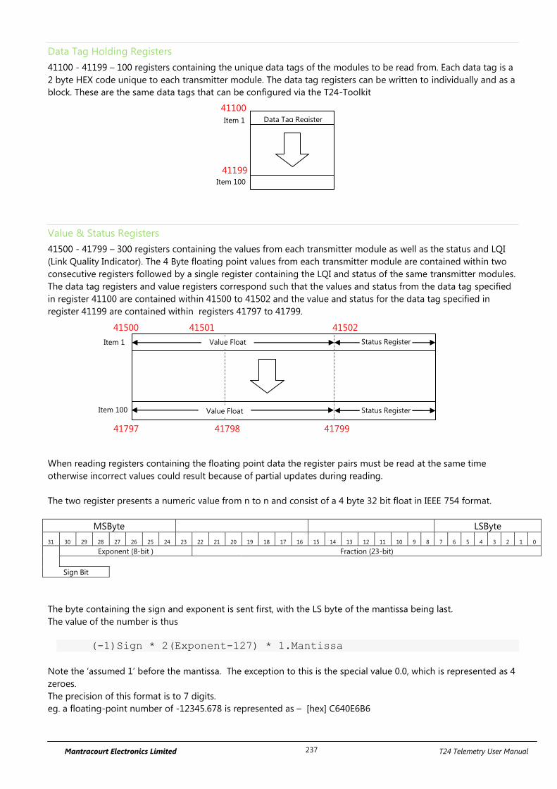
Mantracourt Electronics Limited T24 Telemetry User Manual 237
Data Tag Holding Registers
41100 - 41199 – 100 registers containing the unique data tags of the modules to be read from. Each data tag is a
2 byte HEX code unique to each transmitter module. The data tag registers can be written to individually and as a
block. These are the same data tags that can be configured via the T24-Toolkit
Value & Status Registers
41500 - 41799 – 300 registers containing the values from each transmitter module as well as the status and LQI
(Link Quality Indicator). The 4 Byte floating point values from each transmitter module are contained within two
consecutive registers followed by a single register containing the LQI and status of the same transmitter modules.
The data tag registers and value registers correspond such that the values and status from the data tag specified
in register 41100 are contained within 41500 to 41502 and the value and status for the data tag specified in
register 41199 are contained within registers 41797 to 41799.
When reading registers containing the floating point data the register pairs must be read at the same time
otherwise incorrect values could result because of partial updates during reading.
The two register presents a numeric value from n to n and consist of a 4 byte 32 bit float in IEEE 754 format.
MSByte LSByte
31 30 29 28 27 26 25 24 23 22 21 20 19 18 17 16 15 14 13 12 11 10 9 8 7 6 5 4 3 2 1 0
Exponent (8-bit ) Fraction (23-bit)
Sign Bit
The byte containing the sign and exponent is sent first, with the LS byte of the mantissa being last.
The value of the number is thus
(-1)Sign * 2(Exponent-127) * 1.Mantissa
Note the ‘assumed 1’ before the mantissa. The exception to this is the special value 0.0, which is represented as 4
zeroes.
The precision of this format is to 7 digits.
eg. a floating-point number of -12345.678 is represented as – [hex] C640E6B6
41199
Item 1
Item 100
Data Tag Register
41500
41799
41502
Value Float
41501
Status Register Item 1
Value Float Status Register Item 100
41798 41797
41100
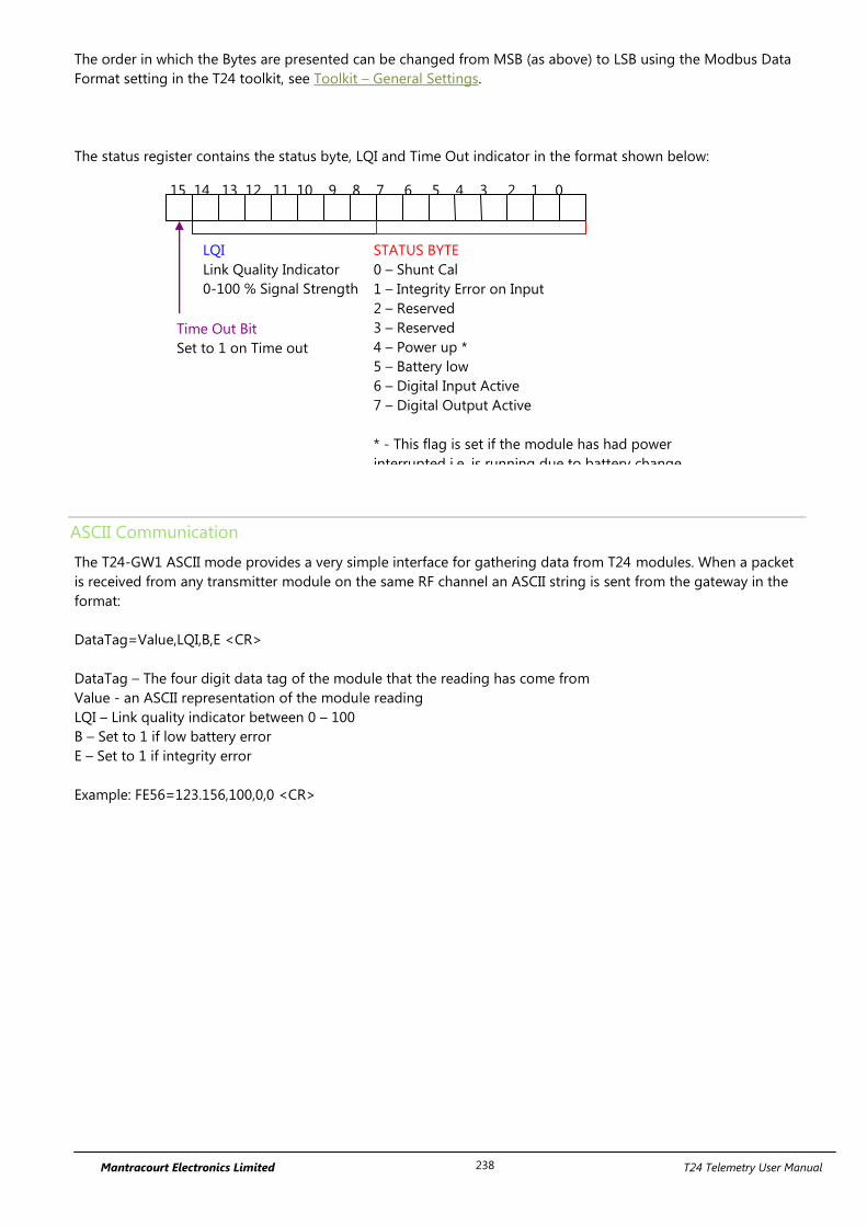
Mantracourt Electronics Limited T24 Telemetry User Manual 238
The order in which the Bytes are presented can be changed from MSB (as above) to LSB using the Modbus Data
Format setting in the T24 toolkit, see Toolkit – General Settings.
The status register contains the status byte, LQI and Time Out indicator in the format shown below:
ASCII Communication
The T24-GW1 ASCII mode provides a very simple interface for gathering data from T24 modules. When a packet
is received from any transmitter module on the same RF channel an ASCII string is sent from the gateway in the
format:
DataTag=Value,LQI,B,E <CR>
DataTag – The four digit data tag of the module that the reading has come from
Value - an ASCII representation of the module reading
LQI – Link quality indicator between 0 – 100
B – Set to 1 if low battery error
E – Set to 1 if integrity error
Example: FE56=123.156,100,0,0 <CR>
15 14 13 12 11 10 9 8 7 6 5 4 3 2 1 0
LQI
Link Quality Indicator
0-100 % Signal Strength
Time Out Bit
Set to 1 on Time out
STATUS BYTE
0 – Shunt Cal
1 – Integrity Error on Input
2 – Reserved
3 – Reserved
4 – Power up *
5 – Battery low
6 – Digital Input Active
7 – Digital Output Active
* - This flag is set if the module has had power
interrupted i.e. is running due to battery change
not woken from sleeping
Mantracourt Electronics Limited T24 Telemetry User Manual 239
Commands
Sending ASCII commands to the gateway will cause the gateway to handle the request but no feedback on the
result is available. The commands will act on all transmitter modules on the same RF channel and group key as
the gateway.
SLEEP <CR> - Sleep all modules that data providers are received from for the sleep duration period. The sleep
duration is set in the T24-Toolkit, see Toolkit – General Settings.
WAKE <CR> - Wake all modules that request to wake for the wake duration period. Sleeping transmitter modules
transmit wake requests every 5 seconds. The wake duration is set in the T24-Toolkit, see Toolkit – General
Settings.
STAYAWAKE <CR> - Issue a stay awake packet to all modules seen for 5 seconds following this command being
executed.
When using RS485 interface issuing commands while the T24-GW1 is outputting is not
possible as the RS485 bus is only half duplex
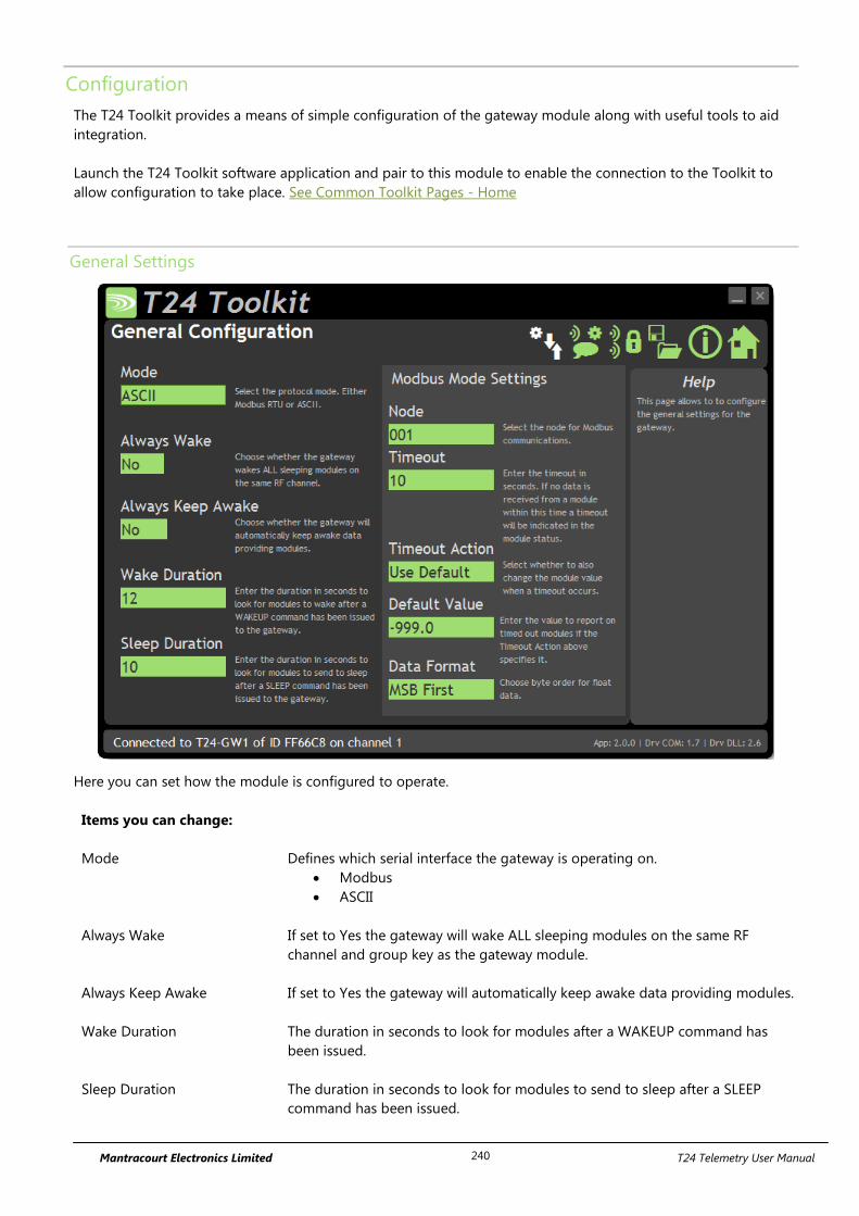
Mantracourt Electronics Limited T24 Telemetry User Manual 240
Configuration
The T24 Toolkit provides a means of simple configuration of the gateway module along with useful tools to aid
integration.
Launch the T24 Toolkit software application and pair to this module to enable the connection to the Toolkit to
allow configuration to take place. See Common Toolkit Pages - Home
General Settings
Here you can set how the module is configured to operate.
Items you can change:
Mode Defines which serial interface the gateway is operating on.
Modbus
ASCII
Always Wake If set to Yes the gateway will wake ALL sleeping modules on the same RF
channel and group key as the gateway module.
Always Keep Awake If set to Yes the gateway will automatically keep awake data providing modules.
Wake Duration
The duration in seconds to look for modules after a WAKEUP command has
been issued.
Sleep Duration
The duration in seconds to look for modules to send to sleep after a SLEEP
command has been issued.
Mantracourt Electronics Limited T24 Telemetry User Manual 241
MODBUS ONLY Settings
Node Is the MODBUS station number or node address of the T24-GW1
Timeout
The time in seconds that if no data is received from a module the gateway will
indicate as timed out.
Timeout Action Defines what value will be reported in the register when a timeout occurs.
Use Default – the value specified as default value will be reported.
Use Last Value – the last value received from the module will be
reported
Default Value This is the value that will be reported in the MODBUS register if a transmitter
module has timed out AND the Timeout Action is set to Use Default.
Data Format In Modbus mode the data from the value register can be displayed in two
formats:
MSB – Most Significant Byte First
LSB – Least Significant Byte First
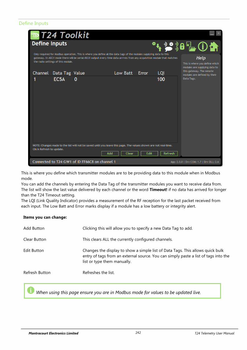
Mantracourt Electronics Limited T24 Telemetry User Manual 242
Define Inputs
This is where you define which transmitter modules are to be providing data to this module when in Modbus
mode.
You can add the channels by entering the Data Tag of the transmitter modules you want to receive data from.
The list will show the last value delivered by each channel or the word Timeout! if no data has arrived for longer
than the T24 Timeout setting.
The LQI (Link Quality Indicator) provides a measurement of the RF reception for the last packet received from
each input. The Low Batt and Error marks display if a module has a low battery or integrity alert.
Items you can change:
Add Button Clicking this will allow you to specify a new Data Tag to add.
Clear Button This clears ALL the currently configured channels.
Edit Button Changes the display to show a simple list of Data Tags. This allows quick bulk
entry of tags from an external source. You can simply paste a list of tags into the
list or type them manually.
Refresh Button Refreshes the list.
When using this page ensure you are in Modbus mode for values to be updated live.

Mantracourt Electronics Limited T24 Telemetry User Manual 243
Enclosure & Mounting
This module is fitted inside our ACM ABS enclosure. Please see Appendix A – Enclosures & Mounting – ACM for
more information.
Antennas
These modules have the antenna already fitted inside the enclosure so there are no specific mounting
requirements.
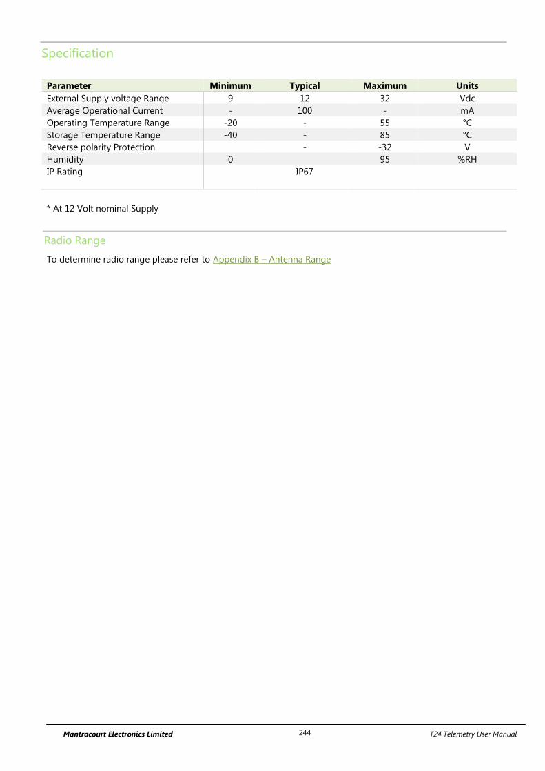
Mantracourt Electronics Limited T24 Telemetry User Manual 244
Specification
Parameter Minimum Typical Maximum Units
External Supply voltage Range 9 12 32 Vdc
Average Operational Current - 100 - mA
Operating Temperature Range -20 - 55 °C
Storage Temperature Range -40 - 85 °C
Reverse polarity Protection - -32 V
Humidity 0 95 %RH
IP Rating IP67
* At 12 Volt nominal Supply
Radio Range
To determine radio range please refer to Appendix B – Antenna Range
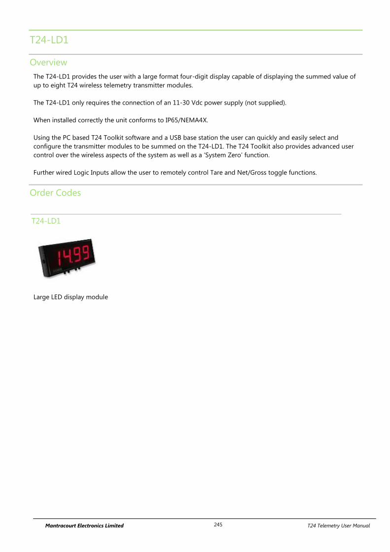
Mantracourt Electronics Limited T24 Telemetry User Manual 245
T24-LD1
Overview
The T24-LD1 provides the user with a large format four-digit display capable of displaying the summed value of
up to eight T24 wireless telemetry transmitter modules.
The T24-LD1 only requires the connection of an 11-30 Vdc power supply (not supplied).
When installed correctly the unit conforms to IP65/NEMA4X.
Using the PC based T24 Toolkit software and a USB base station the user can quickly and easily select and
configure the transmitter modules to be summed on the T24-LD1. The T24 Toolkit also provides advanced user
control over the wireless aspects of the system as well as a ‘System Zero’ function.
Further wired Logic Inputs allow the user to remotely control Tare and Net/Gross toggle functions.
Order Codes
T24-LD1
Large LED display module
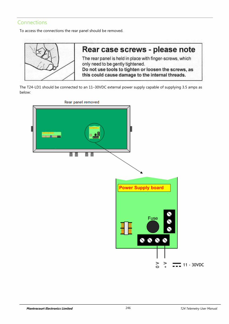
Mantracourt Electronics Limited T24 Telemetry User Manual 246
Connections
To access the connections the rear panel should be removed.
The T24-LD1 should be connected to an 11–30VDC external power supply capable of supplying 3.5 amps as
below:
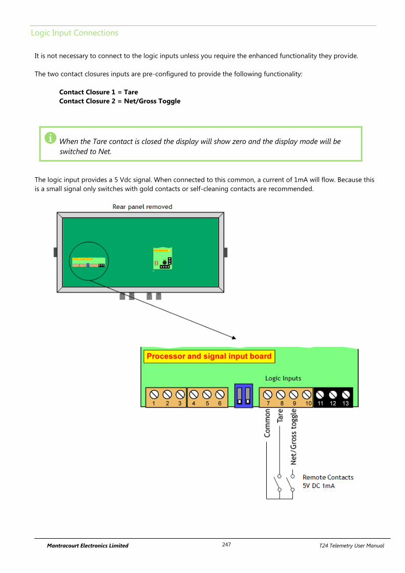
Mantracourt Electronics Limited T24 Telemetry User Manual 247
Logic Input Connections
It is not necessary to connect to the logic inputs unless you require the enhanced functionality they provide.
The two contact closures inputs are pre-configured to provide the following functionality:
Contact Closure 1 = Tare
Contact Closure 2 = Net/Gross Toggle
When the Tare contact is closed the display will show zero and the display mode will be
switched to Net.
The logic input provides a 5 Vdc signal. When connected to this common, a current of 1mA will flow. Because this
is a small signal only switches with gold contacts or self-cleaning contacts are recommended.
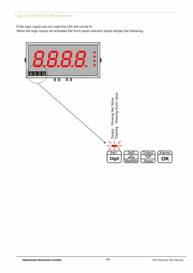
Mantracourt Electronics Limited T24 Telemetry User Manual 248
Logic Input Front Panel indicators
If the logic inputs are not used this LED will not be lit.
When the logic inputs are activated the front panel indicator lamps display the following:
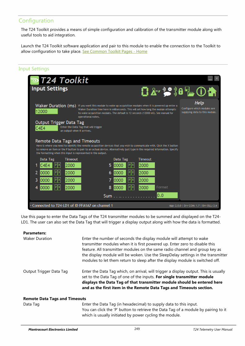
Mantracourt Electronics Limited T24 Telemetry User Manual 249
Configuration
The T24 Toolkit provides a means of simple configuration and calibration of the transmitter module along with
useful tools to aid integration.
Launch the T24 Toolkit software application and pair to this module to enable the connection to the Toolkit to
allow configuration to take place. See Common Toolkit Pages - Home
Input Settings
Use this page to enter the Data Tags of the T24 transmitter modules to be summed and displayed on the T24-
LD1. The user can also set the Data Tag that will trigger a display output along with how the data is formatted.
Parameters:
Waker Duration Enter the number of seconds the display module will attempt to wake
transmitter modules when it is first powered up. Enter zero to disable this
feature. All transmitter modules on the same radio channel and group key as
the display module will be woken. Use the SleepDelay settings in the transmitter
modules to let them return to sleep after the display module is switched off.
Output Trigger Data Tag Enter the Data Tag which, on arrival, will trigger a display output. This is usually
set to the Data Tag of one of the inputs. For single transmitter module
displays the Data Tag of that transmitter module should be entered here
and as the first item in the Remote Data Tags and Timeouts section.
Remote Data Tags and Timeouts
Data Tag Enter the Data Tag (in hexadecimal) to supply data to this input.
You can click the ‘P’ button to retrieve the Data Tag of a module by pairing to it
which is usually initiated by power cycling the module.
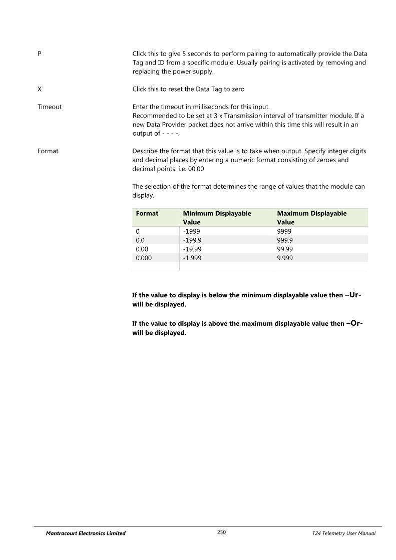
Mantracourt Electronics Limited T24 Telemetry User Manual 250
P Click this to give 5 seconds to perform pairing to automatically provide the Data
Tag and ID from a specific module. Usually pairing is activated by removing and
replacing the power supply.
X Click this to reset the Data Tag to zero
Timeout Enter the timeout in milliseconds for this input.
Recommended to be set at 3 x Transmission interval of transmitter module. If a
new Data Provider packet does not arrive within this time this will result in an
output of - - - -.
Format Describe the format that this value is to take when output. Specify integer digits
and decimal places by entering a numeric format consisting of zeroes and
decimal points. i.e. 00.00
The selection of the format determines the range of values that the module can
display.
Format Minimum Displayable
Value
Maximum Displayable
Value
0 -1999 9999
0.0 -199.9 999.9
0.00 -19.99 99.99
0.000 -1.999 9.999
If the value to display is below the minimum displayable value then –Ur-
will be displayed.
If the value to display is above the maximum displayable value then –Or-
will be displayed.
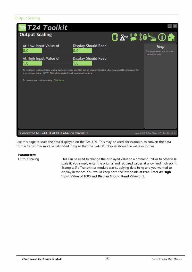
Mantracourt Electronics Limited T24 Telemetry User Manual 251
Output Scaling
Use this page to scale the data displayed on the T24-LD1. This may be used, for example, to convert the data
from a transmitter module calibrated in kg so that the T24-LD1 display shows the value in tonnes.
Parameters:
Output scaling This can be used to change the displayed value to a different unit or to otherwise
scale it. You simply enter the original and required values at a low and high point.
Example: If a Transmitter module was supplying data in kg and you wanted to
display in tonnes. You would keep both the low points at zero. Enter At High
Input Value of 1000 and Display Should Read Value of 1.
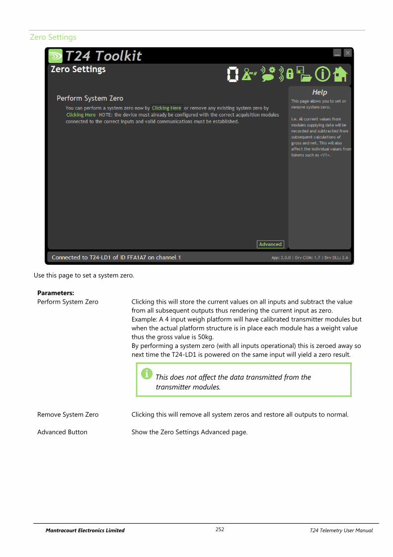
Mantracourt Electronics Limited T24 Telemetry User Manual 252
Zero Settings
Use this page to set a system zero.
Parameters:
Perform System Zero Clicking this will store the current values on all inputs and subtract the value
from all subsequent outputs thus rendering the current input as zero.
Example: A 4 input weigh platform will have calibrated transmitter modules but
when the actual platform structure is in place each module has a weight value
thus the gross value is 50kg.
By performing a system zero (with all inputs operational) this is zeroed away so
next time the T24-LD1 is powered on the same input will yield a zero result.
This does not affect the data transmitted from the
transmitter modules.
Remove System Zero Clicking this will remove all system zeros and restore all outputs to normal.
Advanced Button Show the Zero Settings Advanced page.
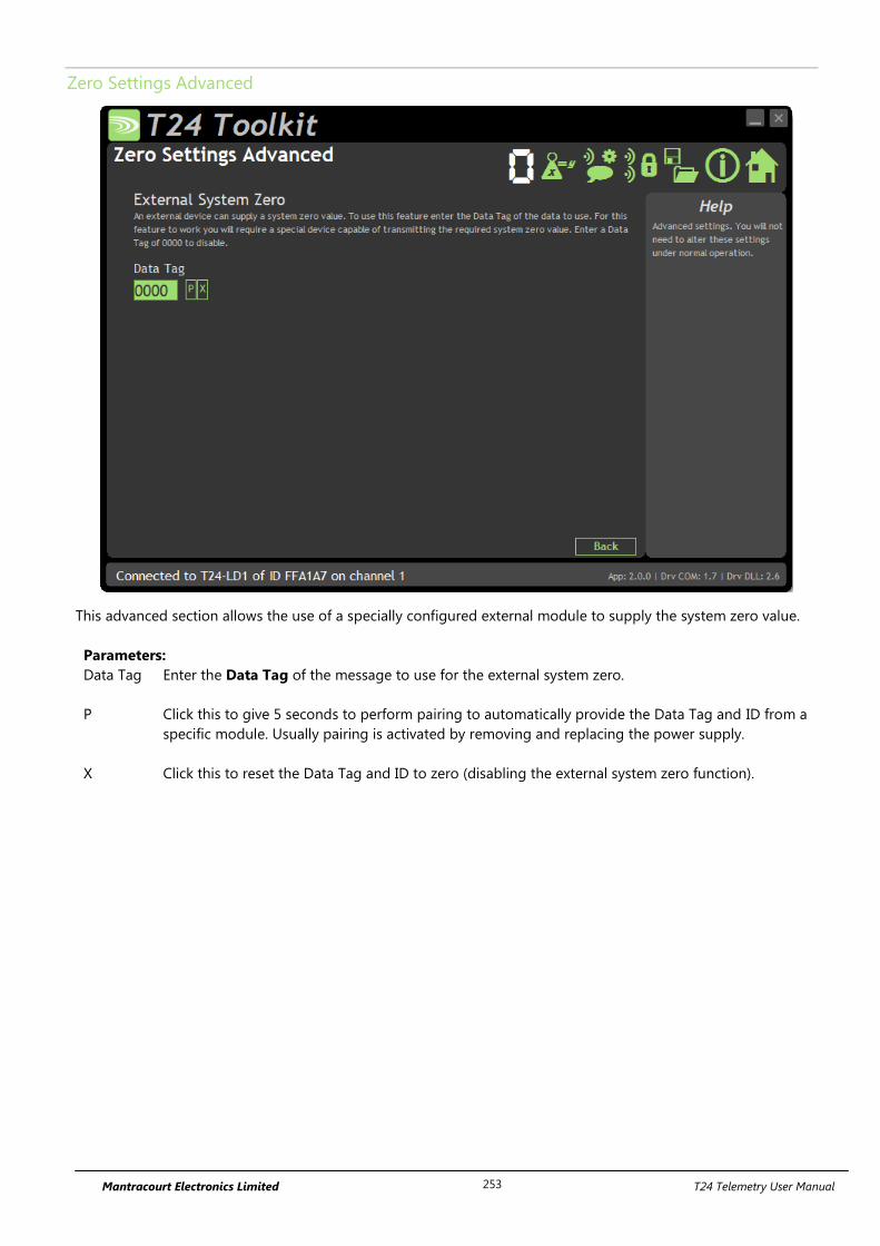
Mantracourt Electronics Limited T24 Telemetry User Manual 253
Zero Settings Advanced
This advanced section allows the use of a specially configured external module to supply the system zero value.
Parameters:
Data Tag Enter the Data Tag of the message to use for the external system zero.
P Click this to give 5 seconds to perform pairing to automatically provide the Data Tag and ID from a
specific module. Usually pairing is activated by removing and replacing the power supply.
X Click this to reset the Data Tag and ID to zero (disabling the external system zero function).
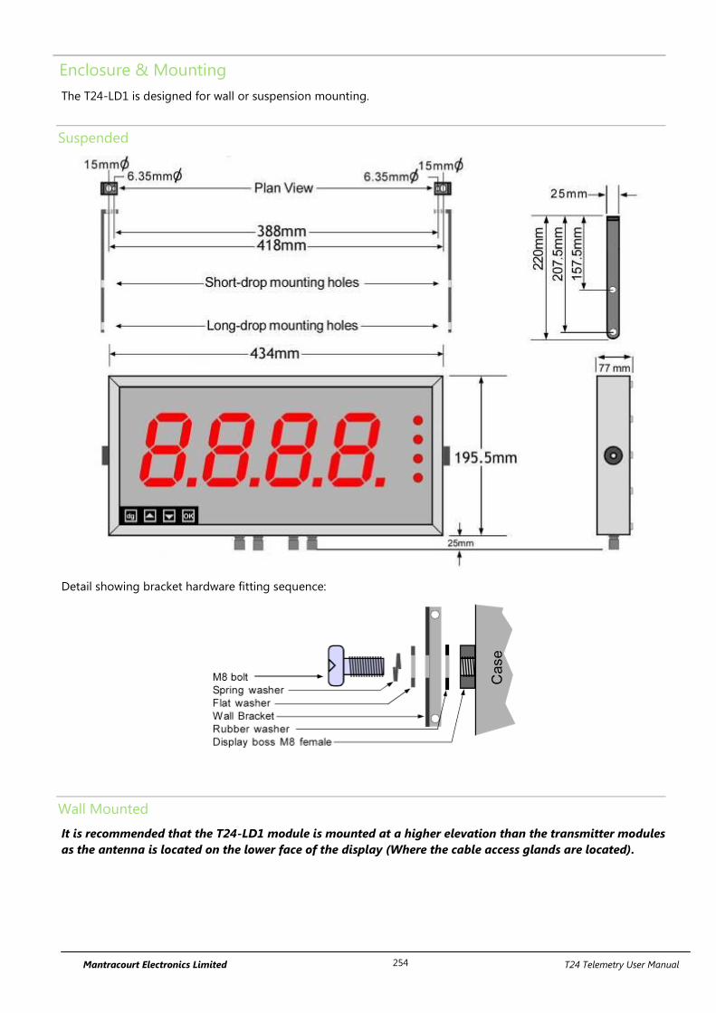
Mantracourt Electronics Limited T24 Telemetry User Manual 254
Enclosure & Mounting
The T24-LD1 is designed for wall or suspension mounting.
Suspended
Detail showing bracket hardware fitting sequence:
Wall Mounted
It is recommended that the T24-LD1 module is mounted at a higher elevation than the transmitter modules
as the antenna is located on the lower face of the display (Where the cable access glands are located).
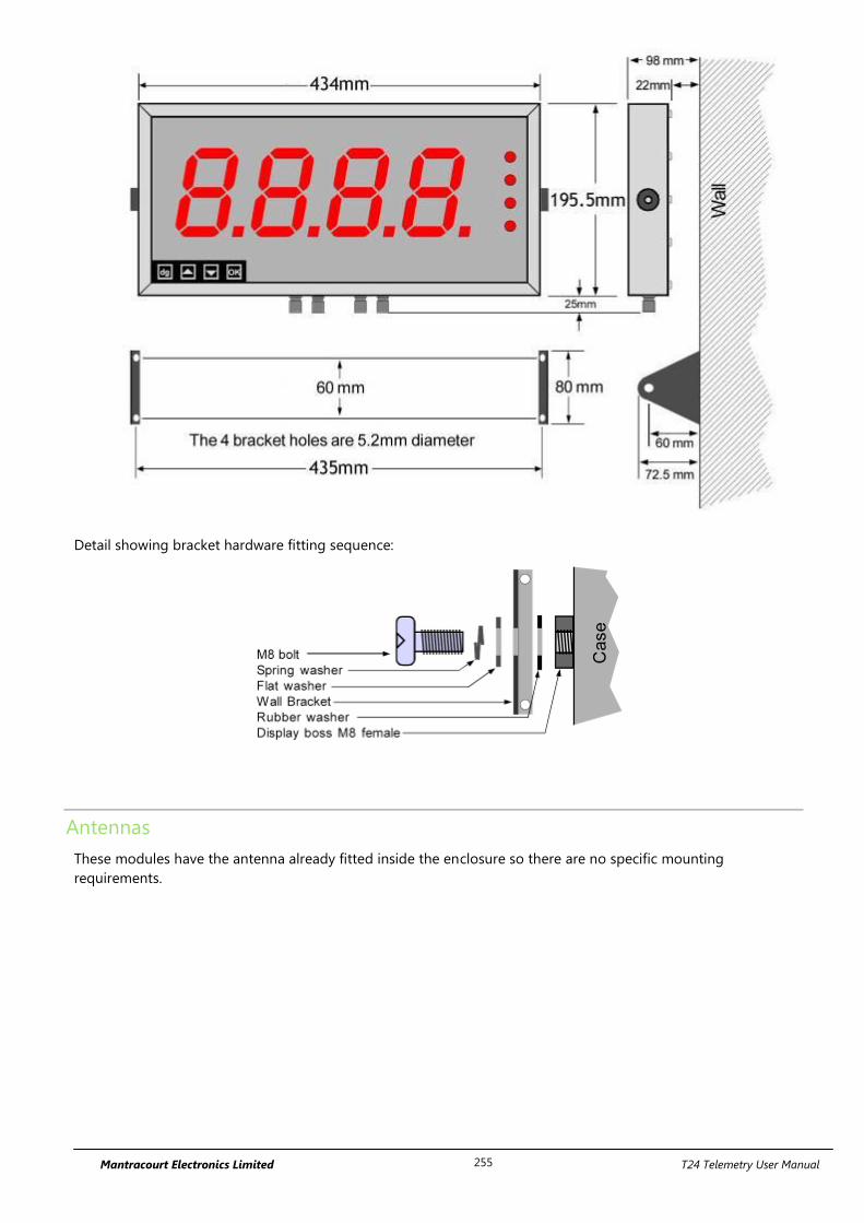
Mantracourt Electronics Limited T24 Telemetry User Manual 255
Detail showing bracket hardware fitting sequence:
Antennas
These modules have the antenna already fitted inside the enclosure so there are no specific mounting
requirements.
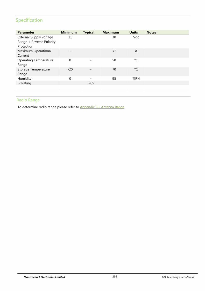
Mantracourt Electronics Limited T24 Telemetry User Manual 256
Specification
Parameter Minimum Typical Maximum Units Notes
External Supply voltage
Range + Reverse Polarity
Protection
11 30 Vdc
Maximum Operational
Current
- 3.5 A
Operating Temperature
Range
0 - 50 °C
Storage Temperature
Range
-20 - 70 °C
Humidity 0 - 95 %RH
IP Rating IP65
Radio Range
To determine radio range please refer to Appendix B – Antenna Range
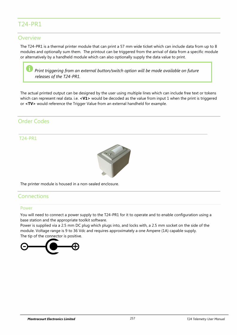
Mantracourt Electronics Limited T24 Telemetry User Manual 257
T24-PR1
Overview
The T24-PR1 is a thermal printer module that can print a 57 mm wide ticket which can include data from up to 8
modules and optionally sum them. The printout can be triggered from the arrival of data from a specific module
or alternatively by a handheld module which can also optionally supply the data value to print.
Print triggering from an external button/switch option will be made available on future
releases of the T24-PR1.
The actual printed output can be designed by the user using multiple lines which can include free text or tokens
which can represent real data. i.e. <V1> would be decoded as the value from input 1 when the print is triggered
or <TV> would reference the Trigger Value from an external handheld for example.
Order Codes
T24-PR1
The printer module is housed in a non-sealed enclosure.
Connections
Power
You will need to connect a power supply to the T24-PR1 for it to operate and to enable configuration using a
base station and the appropriate toolkit software.
Power is supplied via a 2.5 mm DC plug which plugs into, and locks with, a 2.5 mm socket on the side of the
module. Voltage range is 9 to 36 Vdc and requires approximately a one Ampere (1A) capable supply.
The tip of the connector is positive.
Mantracourt Electronics Limited T24 Telemetry User Manual 258
Configuration
Once it has been determined how many modules are feeding data to this module you need to record the Data
Tag that each of these modules are attaching to their Data Provider packets.
These Data Tags are then entered into the ValueDataTagx parameters. Once the rate at which this data arrives is
known you can enter the Timeoutx values.
Leave unused ValueDataTagx parameters with a value of zero to ensure that they are not checked for timeouts
and do not contribute to gross or net sums.
When a data provider packet arrives whose Data Tag matches one of those in the ValueDataTagx parameters the
value it contains will be placed in the Valuex parameter.
If data does not arrive from a module within the Timeoutx period then any reference to either the individual Vx
tokens or one of the summing tokens will result in ------ rather than a numeric value.
The actual serial output can now be constructed using Line1 to Line25 (In the toolkit these are hidden and the
user simply creates the ticket on screen). These parameters take text into which you can insert tokens. When a
'Print' is generated these lines are parsed and tokens replaced with the values they represent and the resulting
data sent to the serial port.
A 'Print' is generated by either issuing a DoPrint command, activating the switch input when SwitchMode is set
to zero or by receiving a Data Provider packet whose Data Tag matches the PrintDataTag parameter.
When a 'Print' is executed each of the parameters Line1 to Line 25 will be parsed. Every token will be evaluated
and replaced with the live value.
The T24 Toolkit provides a means of simple configuration of themodule along with useful tools to aid integration.
Launch the T24 Toolkit software application and pair to this module to enable the connection to the Toolkit to
allow configuration to take place. See Common Toolkit Pages - Home
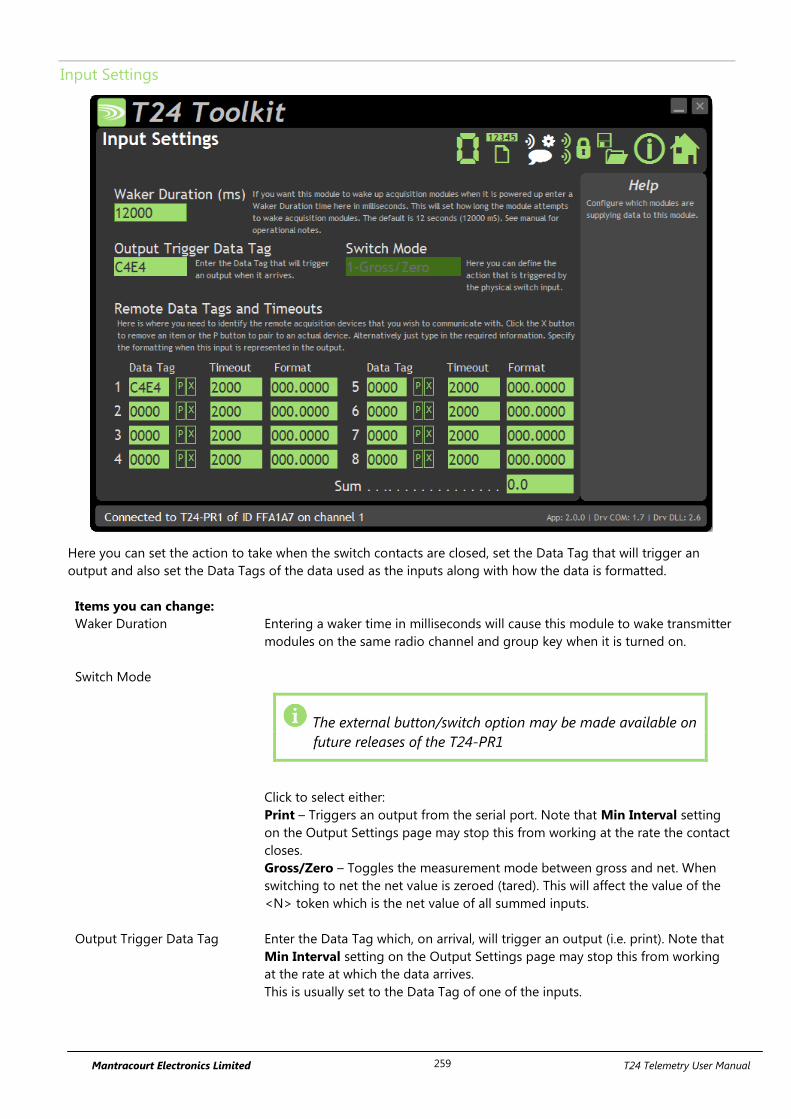
Mantracourt Electronics Limited T24 Telemetry User Manual 259
Input Settings
Here you can set the action to take when the switch contacts are closed, set the Data Tag that will trigger an
output and also set the Data Tags of the data used as the inputs along with how the data is formatted.
Items you can change:
Waker Duration Entering a waker time in milliseconds will cause this module to wake transmitter
modules on the same radio channel and group key when it is turned on.
Switch Mode
The external button/switch option may be made available on
future releases of the T24-PR1
Click to select either:
Print – Triggers an output from the serial port. Note that Min Interval setting
on the Output Settings page may stop this from working at the rate the contact
closes.
Gross/Zero – Toggles the measurement mode between gross and net. When
switching to net the net value is zeroed (tared). This will affect the value of the
<N> token which is the net value of all summed inputs.
Output Trigger Data Tag Enter the Data Tag which, on arrival, will trigger an output (i.e. print). Note that
Min Interval setting on the Output Settings page may stop this from working
at the rate at which the data arrives.
This is usually set to the Data Tag of one of the inputs.
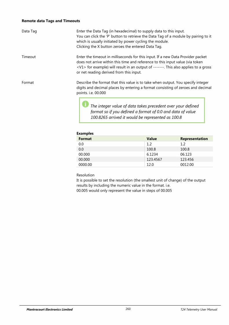
Mantracourt Electronics Limited T24 Telemetry User Manual 260
Remote data Tags and Timeouts
Data Tag Enter the Data Tag (in hexadecimal) to supply data to this input.
You can click the ‘P’ button to retrieve the Data Tag of a module by pairing to it
which is usually initiated by power cycling the module.
Clicking the X button zeroes the entered Data Tag.
Timeout Enter the timeout in milliseconds for this input. If a new Data Provider packet
does not arrive within this time and reference to this input value (via token
<V1> for example) will result in an output of -------. This also applies to a gross
or net reading derived from this input.
Format Describe the format that this value is to take when output. You specify integer
digits and decimal places by entering a format consisting of zeroes and decimal
points. i.e. 00.000
The integer value of data takes precedent over your defined
format so if you defined a format of 0.0 and data of value
100.8265 arrived it would be represented as 100.8
Examples
Format Value Representation
0.0 1.2 1.2
0.0 100.8 100.8
00.000 6.1234 06.123
00.000 123.4567 123.456
0000.00 12.0 0012.00
Resolution
It is possible to set the resolution (the smallest unit of change) of the output
results by including the numeric value in the format. i.e.
00.005 would only represent the value in steps of 00.005
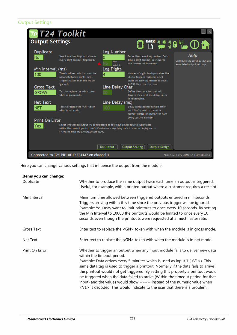
Mantracourt Electronics Limited T24 Telemetry User Manual 261
Output Settings
Here you can change various settings that influence the output from the module.
Items you can change:
Duplicate Whether to produce the same output twice each time an output is triggered.
Useful, for example, with a printed output where a customer requires a receipt.
Min Interval Minimum time allowed between triggered outputs entered in milliseconds.
Triggers arriving within this time since the previous trigger will be ignored.
Example: You may want to limit printouts to once every 10 seconds. By setting
the Min Interval to 10000 the printouts would be limited to once every 10
seconds even though the printouts were requested at a much faster rate.
Gross Text Enter text to replace the <GN> token with when the module is in gross mode.
Net Text Enter text to replace the <GN> token with when the module is in net mode.
Print On Error Whether to trigger an output when any input module fails to deliver new data
within the timeout period.
Example: Data arrives every 5 minutes which is used as input 1 (<V1>). This
same data tag is used to trigger a printout. Normally if the data fails to arrive
the printout would not get triggered. By setting this property a printout would
be triggered when the data failed to arrive (Within the timeout period for that
input) and the values would show ------- instead of the numeric value when
<V1> is decoded. This would indicate to the user that there is a problem.
Mantracourt Electronics Limited T24 Telemetry User Manual 262
Log Number Enter a log number that is used when the <LOG> token is decoded. Each time
an output is triggered this log number is incremented. This number will wrap to
zero once it reaches the maximum value displayable due to the Log Digits.
This parameter is Non Volatile and is stored in internal flash memory each time
the <LOG> token is evaluated in a printout. This takes time and reduces the
finite life of the flash memory so it is recommended that printouts containing
the <LOG> token are not triggered at a rate faster than every 30 seconds.
Log Digits Set the number of digits to display when the <LOG> token is decoded.
Example: If this is set to 2 then the log number will count up to 99 before
resetting.
Line Delay Char This is not alterable and is the character used by the thermal printer to denote
the end of a line. You will see the token <0A> in the Output Design page when
you press the enter key at the end of a line.
Line Delay This is not alterable but shows the delay in milliseconds required at the end of
each printed line.
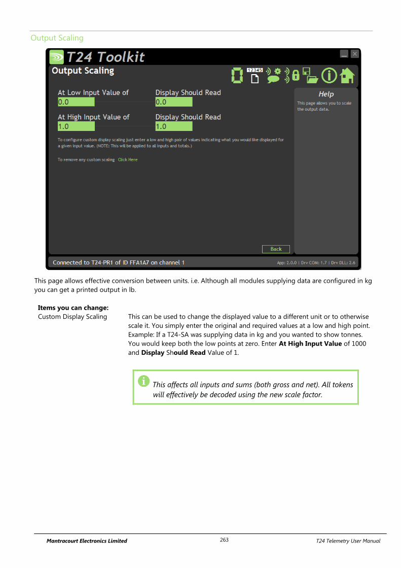
Mantracourt Electronics Limited T24 Telemetry User Manual 263
Output Scaling
This page allows effective conversion between units. i.e. Although all modules supplying data are configured in kg
you can get a printed output in lb.
Items you can change:
Custom Display Scaling This can be used to change the displayed value to a different unit or to otherwise
scale it. You simply enter the original and required values at a low and high point.
Example: If a T24-SA was supplying data in kg and you wanted to show tonnes.
You would keep both the low points at zero. Enter At High Input Value of 1000
and Display Should Read Value of 1.
This affects all inputs and sums (both gross and net). All tokens
will effectively be decoded using the new scale factor.
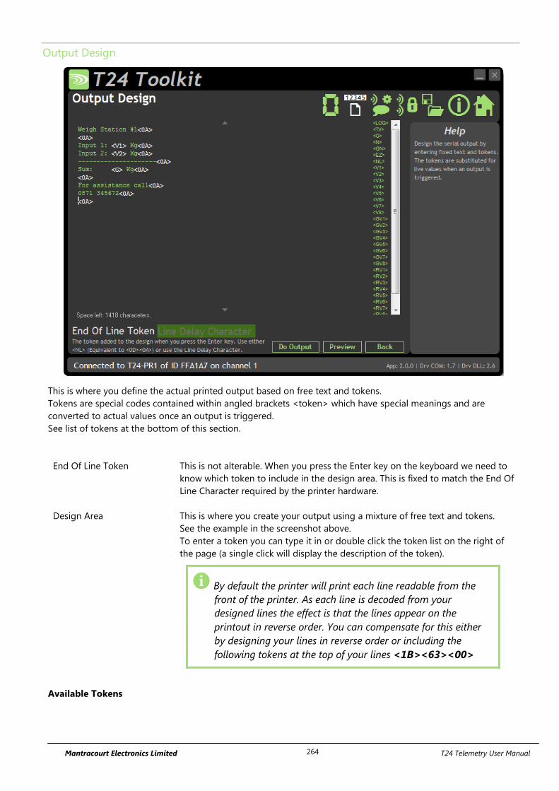
Mantracourt Electronics Limited T24 Telemetry User Manual 264
Output Design
This is where you define the actual printed output based on free text and tokens.
Tokens are special codes contained within angled brackets <token> which have special meanings and are
converted to actual values once an output is triggered.
See list of tokens at the bottom of this section.
End Of Line Token This is not alterable. When you press the Enter key on the keyboard we need to
know which token to include in the design area. This is fixed to match the End Of
Line Character required by the printer hardware.
Design Area This is where you create your output using a mixture of free text and tokens.
See the example in the screenshot above.
To enter a token you can type it in or double click the token list on the right of
the page (a single click will display the description of the token).
By default the printer will print each line readable from the
front of the printer. As each line is decoded from your
designed lines the effect is that the lines appear on the
printout in reverse order. You can compensate for this either
by designing your lines in reverse order or including the
following tokens at the top of your lines <1B><63><00>
Available Tokens
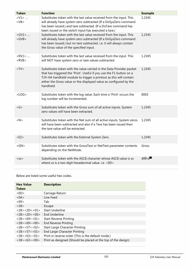
Mantracourt Electronics Limited T24 Telemetry User Manual 265
Token Function Example
<V1> …
<V8>
Substitutes token with the last value received from the input. This
will already have system zero subtracted (If a DoSysZero command
has been issued.) and tare subtracted. (If a DoTare command has
been issued or the switch input has executed a tare.)
1.2345
<GV1> …
<GV8>
Substitutes token with the last value received from the input. This
will already have system zero subtracted (If a DoSysZero command
has been issued.) but no tare subtracted. i.e. it will always contain
the Gross value of the specified input.
1.2345
<RV1> …
<RV8>
Substitutes token with the last value received from the input. This
will NOT have system zero or tare values subtracted.
1.2345
<TV> Substitutes token with the value carried in the Data Provider packet
that has triggered the 'Print'. Useful if you use the F1 button on a
T24-HA handheld module to trigger a printout as this will contain
either the Gross value or the displayed value as configured by the
handheld.
1.2345
<LOG> Substitutes token with the log value. Each time a 'Print' occurs the
log number will be incremented.
0003
<G> Substitutes token with the Gross sum of all active inputs. System
zero values will have been extracted.
1.2345
<N> Substitutes token with the Net sum of all active inputs. System zeros
will have been subtracted and also if a Tare has been issued then
the tare value will be extracted.
1.2345
<EZ> Substitutes token with the External System Zero.
1.2345
<GN> Substitutes token with the GrossText or NetText parameter contents
depending on the NetMode.
Gross
<xx> Substitutes token with the ASCII character whose ASCII value is xx
where xx is a two digit hexadecimal value. i.e. <0D>
ÆӪ-ü▀
Below are listed some useful hex codes.
Hex Value
Token
Description
<0D> Carriage Return
<0A> Line Feed
<09> Tab
<1B> Escape
<1B><2D><01> Start Underline
<1B><2D><00> End Underline
<1B><69><01> Start Reverse Printing
<1B><69><00> End Reverse Printing
<1B><57><02> Start Large Character Printing
<1B><57><01> End Large Character Printing
<1B><63><01> Print in reverse order (This is the default mode.)
<1B><63><00> Print as designed (Should be placed at the top of the design)

Mantracourt Electronics Limited T24 Telemetry User Manual 266
Example
To print the value from input 1 in reverse:
Current Value: 123.456 kg
Use
Current Value: <1B><69><01><V1><1B><69><00> kg
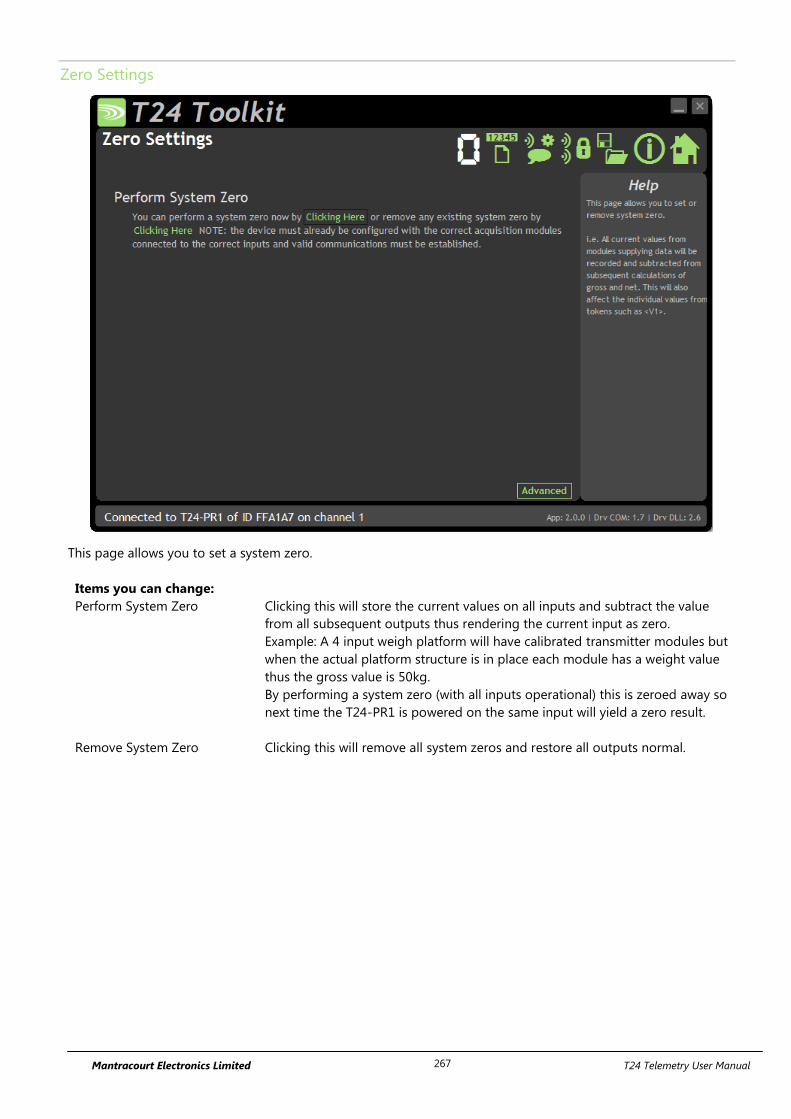
Mantracourt Electronics Limited T24 Telemetry User Manual 267
Zero Settings
This page allows you to set a system zero.
Items you can change:
Perform System Zero Clicking this will store the current values on all inputs and subtract the value
from all subsequent outputs thus rendering the current input as zero.
Example: A 4 input weigh platform will have calibrated transmitter modules but
when the actual platform structure is in place each module has a weight value
thus the gross value is 50kg.
By performing a system zero (with all inputs operational) this is zeroed away so
next time the T24-PR1 is powered on the same input will yield a zero result.
Remove System Zero Clicking this will remove all system zeros and restore all outputs normal.
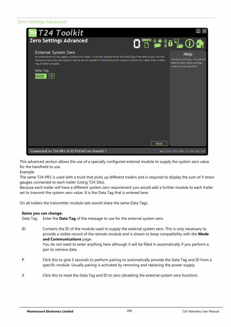
Mantracourt Electronics Limited T24 Telemetry User Manual 268
Zero Settings Advanced
This advanced section allows the use of a specially configured external module to supply the system zero value
for the handheld to use.
Example:
The same T24-PR1 is used with a truck that picks up different trailers and is required to display the sum of 4 strain
gauges connected to each trailer (Using T24-SAs).
Because each trailer will have a different system zero requirement you would add a further module to each trailer
set to transmit the system zero value. It is the Data Tag that is entered here.
On all trailers the transmitter module sets would share the same Data Tags.
Items you can change:
Data Tag Enter the Data Tag of the message to use for the external system zero.
ID Contains the ID of the module used to supply the external system zero. This is only necessary to
provide a visible record of the remote module and is shown to keep compatibility with the Mode
and Communications page.
You do not need to enter anything here although it will be filled in automatically if you perform a
pair to retrieve data.
P Click this to give 5 seconds to perform pairing to automatically provide the Data Tag and ID from a
specific module. Usually pairing is activated by removing and replacing the power supply.
X Click this to reset the Data Tag and ID to zero (disabling the external system zero function).
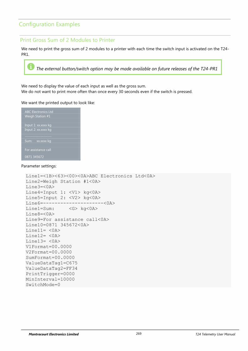
Mantracourt Electronics Limited T24 Telemetry User Manual 269
Configuration Examples
Print Gross Sum of 2 Modules to Printer
We need to print the gross sum of 2 modules to a printer with each time the switch input is activated on the T24-
PR1.
The external button/switch option may be made available on future releases of the T24-PR1
We need to display the value of each input as well as the gross sum.
We do not want to print more often than once every 30 seconds even if the switch is pressed.
We want the printed output to look like:
ABC Electronics Ltd
Weigh Station #1
Input 1: xx.xxxx kg
Input 2: xx.xxxx kg
--------------------
Sum: xx.xxxx kg
For assistance call
0871 345672
Parameter settings:
Line1=<1B><63><00><0A>ABC Electronics Ltd<0A>
Line2=Weigh Station #1<0A>
Line3=<0A>
Line4=Input 1: <V1> kg<0A>
Line5=Input 2: <V2> kg<0A>
Line6=---------------------<0A>
Line1=Sum: <G> kg<0A>
Line8=<0A>
Line9=For assistance call<0A>
Line10=0871 345672<0A>
Line11= <0A>
Line12= <0A>
Line13= <0A>
V1Format=00.0000
V2Format=00.0000
SumFormat=00.0000
ValueDataTag1=C675
ValueDataTag2=FF34
PrintTrigger=0000
MinInterval=10000
SwitchMode=0
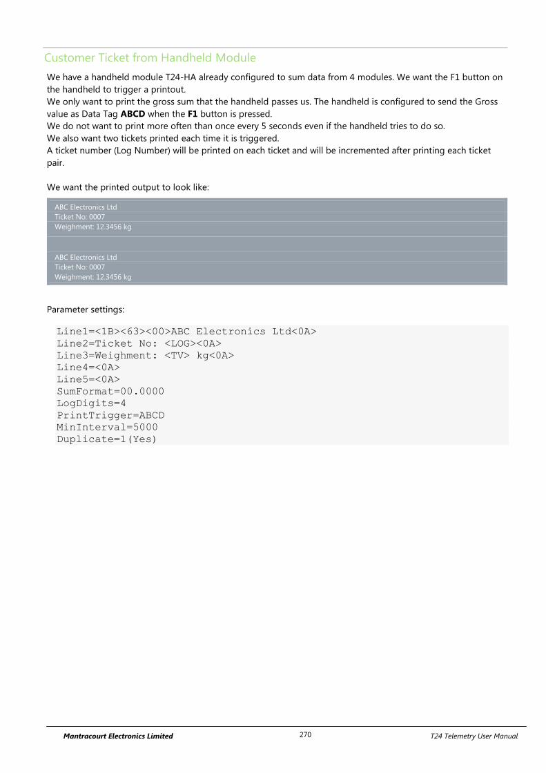
Mantracourt Electronics Limited T24 Telemetry User Manual 270
Customer Ticket from Handheld Module
We have a handheld module T24-HA already configured to sum data from 4 modules. We want the F1 button on
the handheld to trigger a printout.
We only want to print the gross sum that the handheld passes us. The handheld is configured to send the Gross
value as Data Tag ABCD when the F1 button is pressed.
We do not want to print more often than once every 5 seconds even if the handheld tries to do so.
We also want two tickets printed each time it is triggered.
A ticket number (Log Number) will be printed on each ticket and will be incremented after printing each ticket
pair.
We want the printed output to look like:
ABC Electronics Ltd
Ticket No: 0007
Weighment: 12.3456 kg
ABC Electronics Ltd
Ticket No: 0007
Weighment: 12.3456 kg
Parameter settings:
Line1=<1B><63><00>ABC Electronics Ltd<0A>
Line2=Ticket No: <LOG><0A>
Line3=Weighment: <TV> kg<0A>
Line4=<0A>
Line5=<0A>
SumFormat=00.0000
LogDigits=4
PrintTrigger=ABCD
MinInterval=5000
Duplicate=1(Yes)
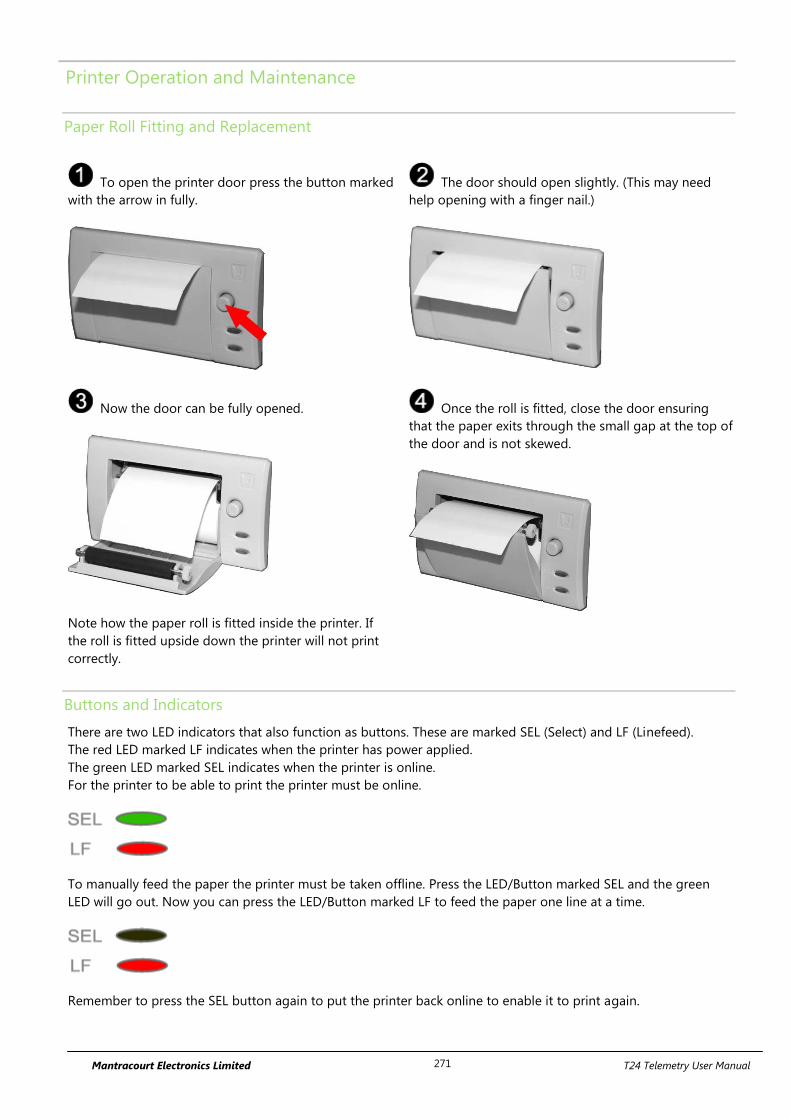
Mantracourt Electronics Limited T24 Telemetry User Manual 271
Printer Operation and Maintenance
Paper Roll Fitting and Replacement
To open the printer door press the button marked
with the arrow in fully.
The door should open slightly. (This may need
help opening with a finger nail.)
Now the door can be fully opened.
Note how the paper roll is fitted inside the printer. If
the roll is fitted upside down the printer will not print
correctly.
Once the roll is fitted, close the door ensuring
that the paper exits through the small gap at the top of
the door and is not skewed.
Buttons and Indicators
There are two LED indicators that also function as buttons. These are marked SEL (Select) and LF (Linefeed).
The red LED marked LF indicates when the printer has power applied.
The green LED marked SEL indicates when the printer is online.
For the printer to be able to print the printer must be online.
To manually feed the paper the printer must be taken offline. Press the LED/Button marked SEL and the green
LED will go out. Now you can press the LED/Button marked LF to feed the paper one line at a time.
Remember to press the SEL button again to put the printer back online to enable it to print again.
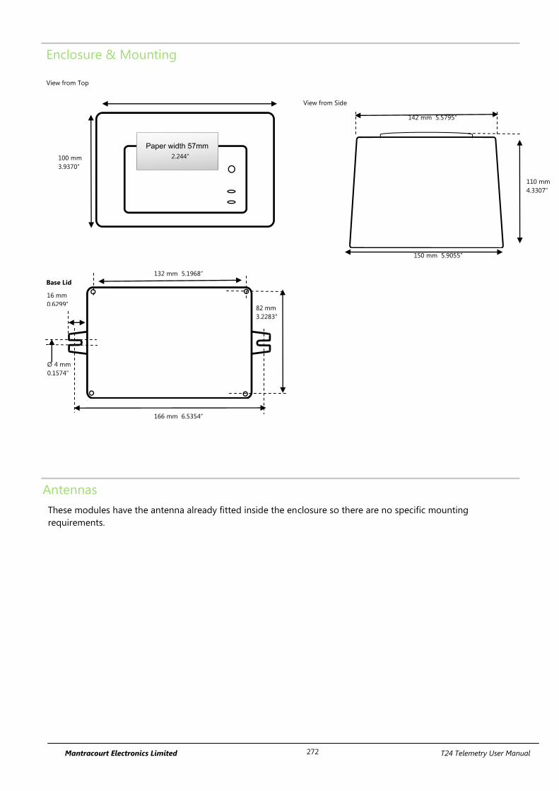
Mantracourt Electronics Limited T24 Telemetry User Manual 272
Enclosure & Mounting
View from Top
View from Side
Base Lid
Antennas
These modules have the antenna already fitted inside the enclosure so there are no specific mounting
requirements.
100 mm
3.9370”
110 mm
4.3307”
150 mm 5.9055”
Ø 4.55mm
142 mm 5.5795”
2.244”
16 mm
0.6299” 82 mm
3.2283”
132 mm 5.1968”
166 mm 6.5354”
Ø 4 mm
0.1574”
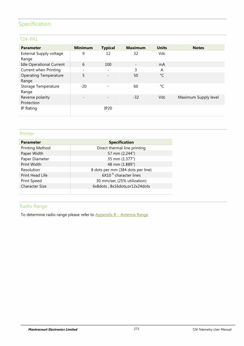
Mantracourt Electronics Limited T24 Telemetry User Manual 273
Specification
T24-PR1
Parameter Minimum Typical Maximum Units Notes
External Supply voltage
Range
9 12 32 Vdc
Idle Operational Current 6 100 - mA
Current when Printing - - 3 A
Operating Temperature
Range
5 - 50 °C
Storage Temperature
Range
-20 - 60 °C
Reverse polarity
Protection
- - -32 Vdc Maximum Supply level
IP Rating IP20
Printer
Parameter Specification
Printing Method Direct thermal line printing
Paper Width 57 mm (2.244”)
Paper Diameter 35 mm (1.377”)
Print Width 48 mm (1.889”)
Resolution 8 dots per mm (384 dots per line)
Print Head Life 6X10 6 character lines
Print Speed 30 mm/sec (25% utilization)
Character Size 6x8dots , 8x16dots,or12x24dots
Radio Range
To determine radio range please refer to Appendix B – Antenna Range
Mantracourt Electronics Limited T24 Telemetry User Manual 274
T24-RDC-1, T24-RDC-2, T24-RDC-5, T24-RDC-10, T24-RDC-200
Overview
The T24-RDC collects data from remote T24 transmitter modules and generates CSV files, custom SMS reports
and triggered reports that are delivered over the cellular GPRS network and GSM network for SMS messaging.
You can either define the active group of remote transmitter modules or allow the module to work automatically,
adding new modules as it detects them.
The main logging functionality is to collect data from the remote modules and place the results into a CSV file.
You can specify the amount of data stored in the CSV file by setting the age of data it contains.
You can also specify at what interval the CSV file is delivered to up to 3 destinations which can be an email
address, SMS phone number, FTP server, raw socket or delivered as an HTTP POST to a web server. This allows a
very flexible level of control over what data is reported and when.
For example, you may want to collect and report only 24 hours worth of data at a time or possibly collect data
over one month but still report 1 months worth of data weekly.
SMS reports can be user designed to deliver the data values from specific modules and be triggered by sending
an SMS message to the module. Up to 10 SMS reports can be designed. The remote modules can be referenced
either by channel number or data tag. These reports are always sent back to the phone that triggered the
message.
Up to 20 triggered reports can be user designed that can look for individual modules exceeding limits, reporting
errors or local events such as loss of external power and lid open, or even just at set intervals.
These alerts can deliver a custom message (that can refer to the channels and values that caused the error) to an
email address, SMS phone number, FTP server, raw socket or delivered as an HTTP POST to a web server.
A single alert can be defined to cover a range or all modules but in this case individual
values cannot be reported, just the fact that channels 1,3,4-8 have exceeded set limits etc.
SMS messaging may also be used to change or update certain user parameters of the module. i.e. You may
change a delivery destination of a report or change the interval of reporting. This saves on costly site visits for
minor operational changes.
The module has an internal Li-ion battery which can act as battery backup, or in low power mode, may power the
module for the required period of operation. An external power supply can increase the operation periods and
may be a permanent supply or batteries. The internal battery is recharged by the external power supply.
There are three operational modes: Normal, Low Power and Ultra Low Power. In normal mode incoming SMS
messages are processed as they are received and triggered reports are checked in real time. In low power mode
the whole module sleeps between captures so cannot act on incoming SMS messages or triggered reports until it
next wakes at the log interval. In Ultra Low Power mode the SMS reports and triggered reports are not actioned
until the CSV data send interval.
The RDC is a Remote Data Collection module which communicates using GSM/GPRS and therefore is bound by
the restrictions and limitations of a mobile data network. This can include but is not limited to partial or complete
loss of coverage, environmental interference or network faults.

Mantracourt Electronics Limited T24 Telemetry User Manual 275
Order Codes
T24-RDC-1, T24-RDC-2, T24-RDC-5, T24-RDC-10, T24-RDC-200
All T24-RDC variants are fitted within a weatherproof enclosure.
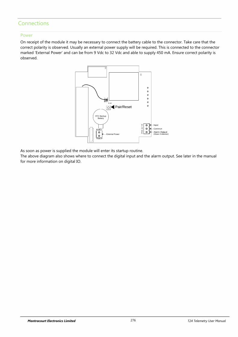
Mantracourt Electronics Limited T24 Telemetry User Manual 276
Connections
Power
On receipt of the module it may be necessary to connect the battery cable to the connector. Take care that the
correct polarity is observed. Usually an external power supply will be required. This is connected to the connector
marked ‘External Power’ and can be from 9 Vdc to 32 Vdc and able to supply 450 mA. Ensure correct polarity is
observed.
External Power
RTC BackupBattery
Pair/Reset
As soon as power is supplied the module will enter its startup routine.
The above diagram also shows where to connect the digital input and the alarm output. See later in the manual
for more information on digital IO.
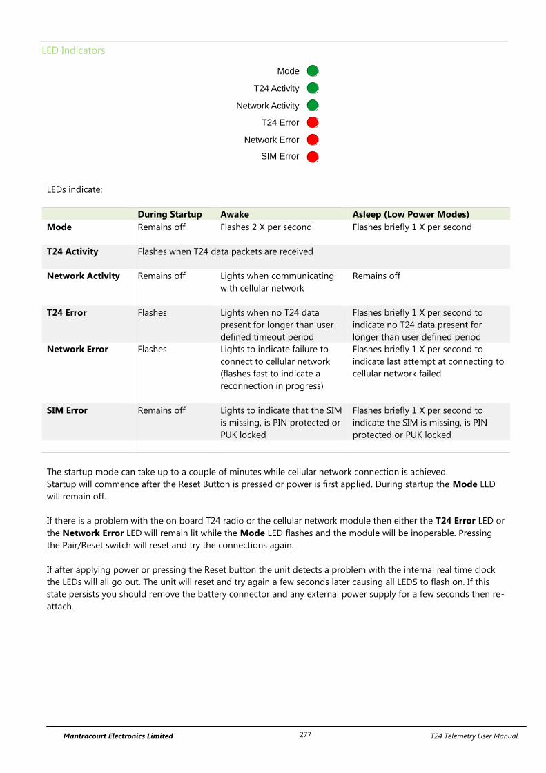
Mantracourt Electronics Limited T24 Telemetry User Manual 277
LED Indicators
Mode
T24 Activity
Network Activity
T24 Error
Network Error
SIM Error
LEDs indicate:
During Startup Awake Asleep (Low Power Modes)
Mode Remains off Flashes 2 X per second
Flashes briefly 1 X per second
T24 Activity Flashes when T24 data packets are received
Network Activity Remains off Lights when communicating
with cellular network
Remains off
T24 Error Flashes Lights when no T24 data
present for longer than user
defined timeout period
Flashes briefly 1 X per second to
indicate no T24 data present for
longer than user defined period
Network Error Flashes Lights to indicate failure to
connect to cellular network
(flashes fast to indicate a
reconnection in progress)
Flashes briefly 1 X per second to
indicate last attempt at connecting to
cellular network failed
SIM Error Remains off Lights to indicate that the SIM
is missing, is PIN protected or
PUK locked
Flashes briefly 1 X per second to
indicate the SIM is missing, is PIN
protected or PUK locked
The startup mode can take up to a couple of minutes while cellular network connection is achieved.
Startup will commence after the Reset Button is pressed or power is first applied. During startup the Mode LED
will remain off.
If there is a problem with the on board T24 radio or the cellular network module then either the T24 Error LED or
the Network Error LED will remain lit while the Mode LED flashes and the module will be inoperable. Pressing
the Pair/Reset switch will reset and try the connections again.
If after applying power or pressing the Reset button the unit detects a problem with the internal real time clock
the LEDs will all go out. The unit will reset and try again a few seconds later causing all LEDS to flash on. If this
state persists you should remove the battery connector and any external power supply for a few seconds then re-
attach.
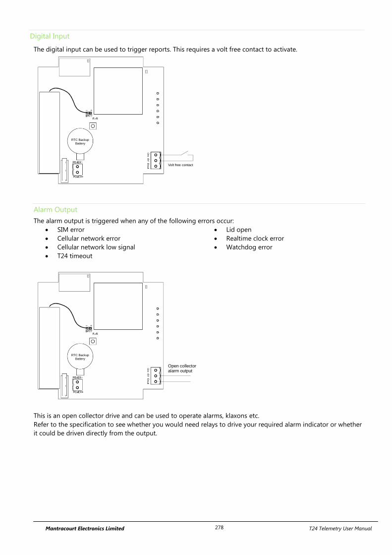
Mantracourt Electronics Limited T24 Telemetry User Manual 278
Digital Input
The digital input can be used to trigger reports. This requires a volt free contact to activate.
RTC BackupBattery
Volt free contact
Alarm Output
The alarm output is triggered when any of the following errors occur:
SIM error
Cellular network error
Cellular network low signal
T24 timeout
Lid open
Realtime clock error
Watchdog error
RTC BackupBattery
Open collectoralarm output
This is an open collector drive and can be used to operate alarms, klaxons etc.
Refer to the specification to see whether you would need relays to drive your required alarm indicator or whether
it could be driven directly from the output.
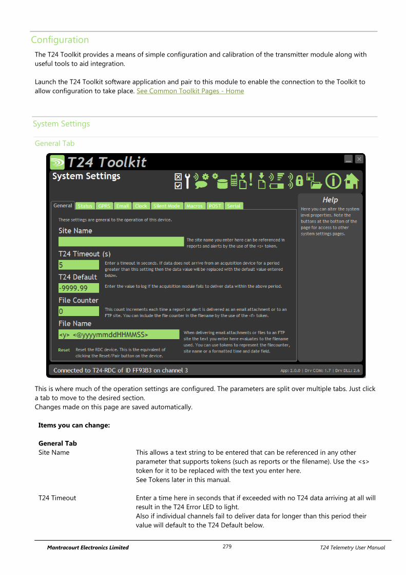
Mantracourt Electronics Limited T24 Telemetry User Manual 279
Configuration
The T24 Toolkit provides a means of simple configuration and calibration of the transmitter module along with
useful tools to aid integration.
Launch the T24 Toolkit software application and pair to this module to enable the connection to the Toolkit to
allow configuration to take place. See Common Toolkit Pages - Home
System Settings
General Tab
This is where much of the operation settings are configured. The parameters are split over multiple tabs. Just click
a tab to move to the desired section.
Changes made on this page are saved automatically.
Items you can change:
General Tab
Site Name This allows a text string to be entered that can be referenced in any other
parameter that supports tokens (such as reports or the filename). Use the <s>
token for it to be replaced with the text you enter here.
See Tokens later in this manual.
T24 Timeout Enter a time here in seconds that if exceeded with no T24 data arriving at all will
result in the T24 Error LED to light.
Also if individual channels fail to deliver data for longer than this period their
value will default to the T24 Default below.

Mantracourt Electronics Limited T24 Telemetry User Manual 280
T24 Default The default value to log when data fails to arrive from a particular channel.
File Counter Enter a numeric value that is incremented each time a report or CSV data is
delivered to an FTP or email destination.
This counter can be referenced by any parameter using tokens by using the <f>
token.
File Name You can set the filename text to use whenever a file is delivered to an FTP server
(Either reports or the CSV data) or to an email address (CSV data).
The filename is common to all but you can make use of tokens to make each
file unique.
Do not specify an extension. CSV data will be allocated a .CSV extension and
reports will be allocated a .TXT extension.
Useful tokens include <s>, <y>, <f> and <@xxx> date time formatted tokens.
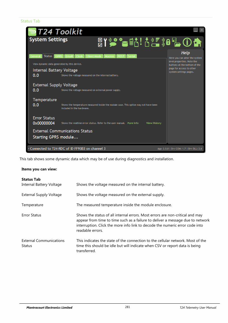
Mantracourt Electronics Limited T24 Telemetry User Manual 281
Status Tab
This tab shows some dynamic data which may be of use during diagnostics and installation.
Items you can view:
Status Tab
Internal Battery Voltage Shows the voltage measured on the internal battery.
External Supply Voltage Shows the voltage measured on the external supply.
Temperature The measured temperature inside the module enclosure.
Error Status Shows the status of all internal errors. Most errors are non-critical and may
appear from time to time such as a failure to deliver a message due to network
interruption. Click the more info link to decode the numeric error code into
readable errors.
External Communications
Status
This indicates the state of the connection to the cellular network. Most of the
time this should be idle but will indicate when CSV or report data is being
transferred.
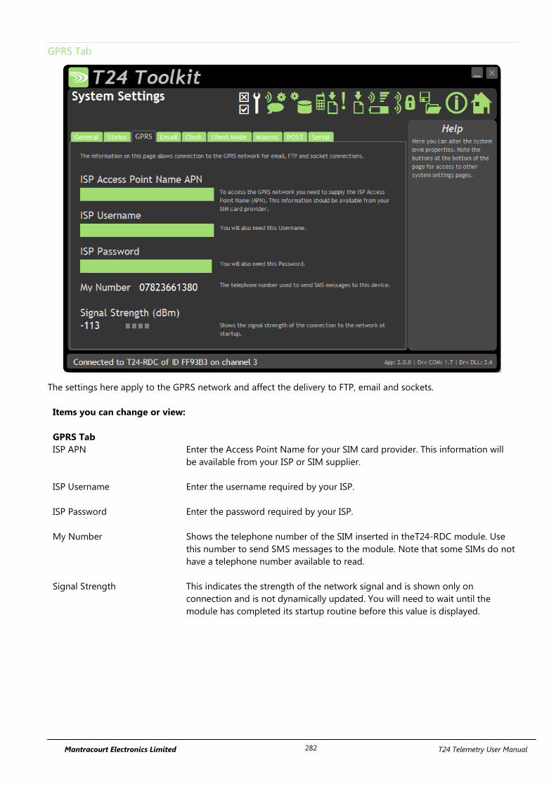
Mantracourt Electronics Limited T24 Telemetry User Manual 282
GPRS Tab
The settings here apply to the GPRS network and affect the delivery to FTP, email and sockets.
Items you can change or view:
GPRS Tab
ISP APN Enter the Access Point Name for your SIM card provider. This information will
be available from your ISP or SIM supplier.
ISP Username Enter the username required by your ISP.
ISP Password Enter the password required by your ISP.
My Number Shows the telephone number of the SIM inserted in theT24-RDC module. Use
this number to send SMS messages to the module. Note that some SIMs do not
have a telephone number available to read.
Signal Strength This indicates the strength of the network signal and is shown only on
connection and is not dynamically updated. You will need to wait until the
module has completed its startup routine before this value is displayed.
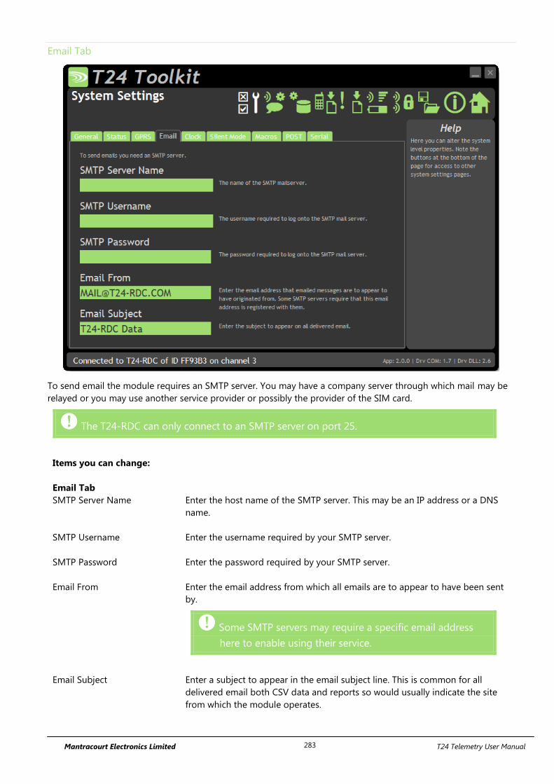
Mantracourt Electronics Limited T24 Telemetry User Manual 283
Email Tab
To send email the module requires an SMTP server. You may have a company server through which mail may be
relayed or you may use another service provider or possibly the provider of the SIM card.
The T24-RDC can only connect to an SMTP server on port 25.
Items you can change:
Email Tab
SMTP Server Name Enter the host name of the SMTP server. This may be an IP address or a DNS
name.
SMTP Username Enter the username required by your SMTP server.
SMTP Password Enter the password required by your SMTP server.
Email From Enter the email address from which all emails are to appear to have been sent
by.
Some SMTP servers may require a specific email address
here to enable using their service.
Email Subject Enter a subject to appear in the email subject line. This is common for all
delivered email both CSV data and reports so would usually indicate the site
from which the module operates.
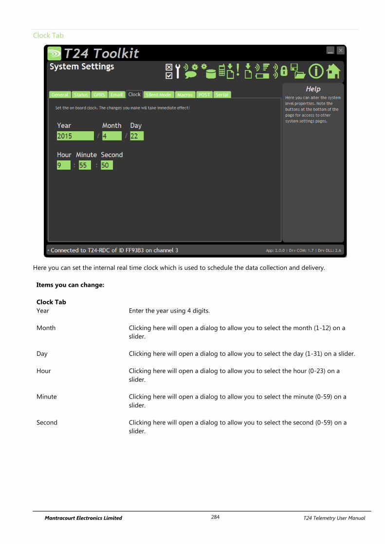
Mantracourt Electronics Limited T24 Telemetry User Manual 284
Clock Tab
Here you can set the internal real time clock which is used to schedule the data collection and delivery.
Items you can change:
Clock Tab
Year Enter the year using 4 digits.
Month Clicking here will open a dialog to allow you to select the month (1-12) on a
slider.
Day Clicking here will open a dialog to allow you to select the day (1-31) on a slider.
Hour Clicking here will open a dialog to allow you to select the hour (0-23) on a
slider.
Minute Clicking here will open a dialog to allow you to select the minute (0-59) on a
slider.
Second Clicking here will open a dialog to allow you to select the second (0-59) on a
slider.
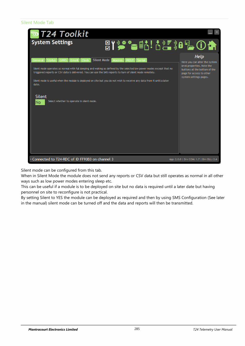
Mantracourt Electronics Limited T24 Telemetry User Manual 285
Silent Mode Tab
Silent mode can be configured from this tab.
When in Silent Mode the module does not send any reports or CSV data but still operates as normal in all other
ways such as low power modes entering sleep etc.
This can be useful if a module is to be deployed on site but no data is required until a later date but having
personnel on site to reconfigure is not practical.
By setting Silent to YES the module can be deployed as required and then by using SMS Configuration (See later
in the manual) silent mode can be turned off and the data and reports will then be transmitted.
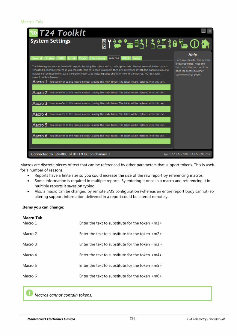
Mantracourt Electronics Limited T24 Telemetry User Manual 286
Macros Tab
Macros are discrete pieces of text that can be referenced by other parameters that support tokens. This is useful
for a number of reasons.
Reports have a finite size so you could increase the size of the raw report by referencing macros.
Some information is required in multiple reports. By entering it once in a macro and referencing it in
multiple reports it saves on typing.
Also a macro can be changed by remote SMS configuration (whereas an entire report body cannot) so
altering support information delivered in a report could be altered remotely.
Items you can change:
Macro Tab
Macro 1 Enter the text to substitute for the token <m1>
Macro 2 Enter the text to substitute for the token <m2>
Macro 3 Enter the text to substitute for the token <m3>
Macro 4 Enter the text to substitute for the token <m4>
Macro 5 Enter the text to substitute for the token <m5>
Macro 6 Enter the text to substitute for the token <m6>
Macros cannot contain tokens.
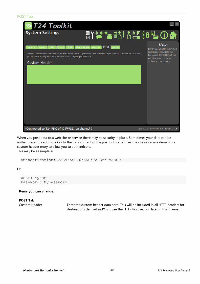
Mantracourt Electronics Limited T24 Telemetry User Manual 287
POST Tab
When you post data to a web site or service there may be security in place. Sometimes your data can be
authenticated by adding a key to the data content of the post but sometimes the site or service demands a
custom header entry to allow you to authenticate.
This may be as simple as:
Authentication: AAS56ASD765ASD57ASD5575ADSD
Or
User: Myname
Password: Mypassword
Items you can change:
POST Tab
Custom Header Enter the custom header data here. This will be included in all HTTP headers for
destinations defined as POST. See the HTTP Post section later in this manual.
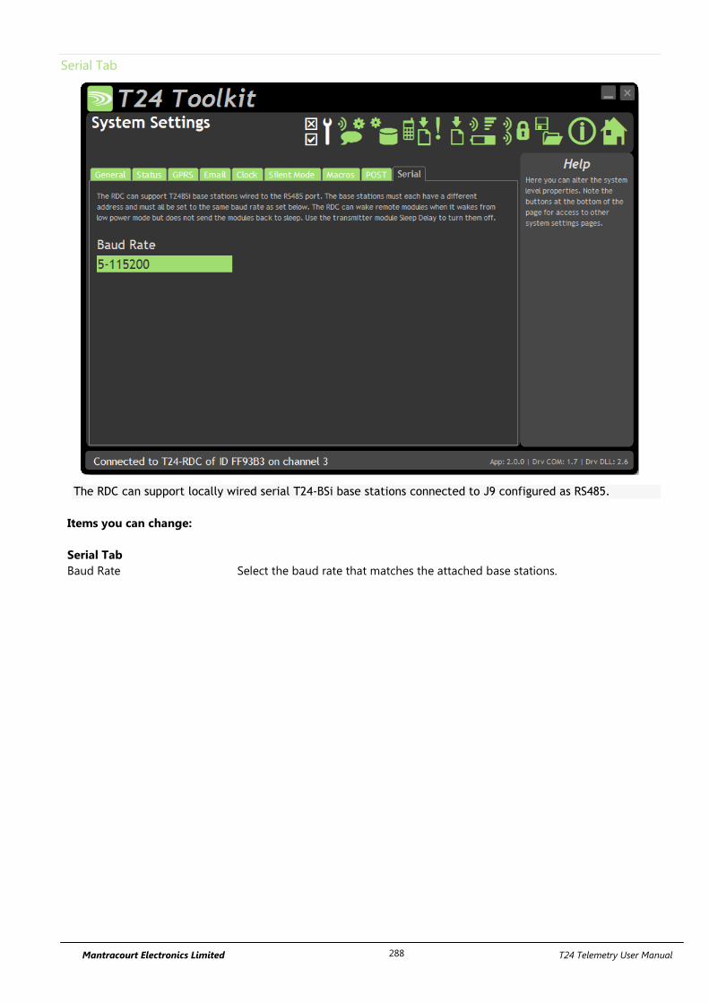
Mantracourt Electronics Limited T24 Telemetry User Manual 288
Serial Tab
The RDC can support locally wired serial T24-BSi base stations connected to J9 configured as RS485.
Items you can change:
Serial Tab
Baud Rate Select the baud rate that matches the attached base stations.
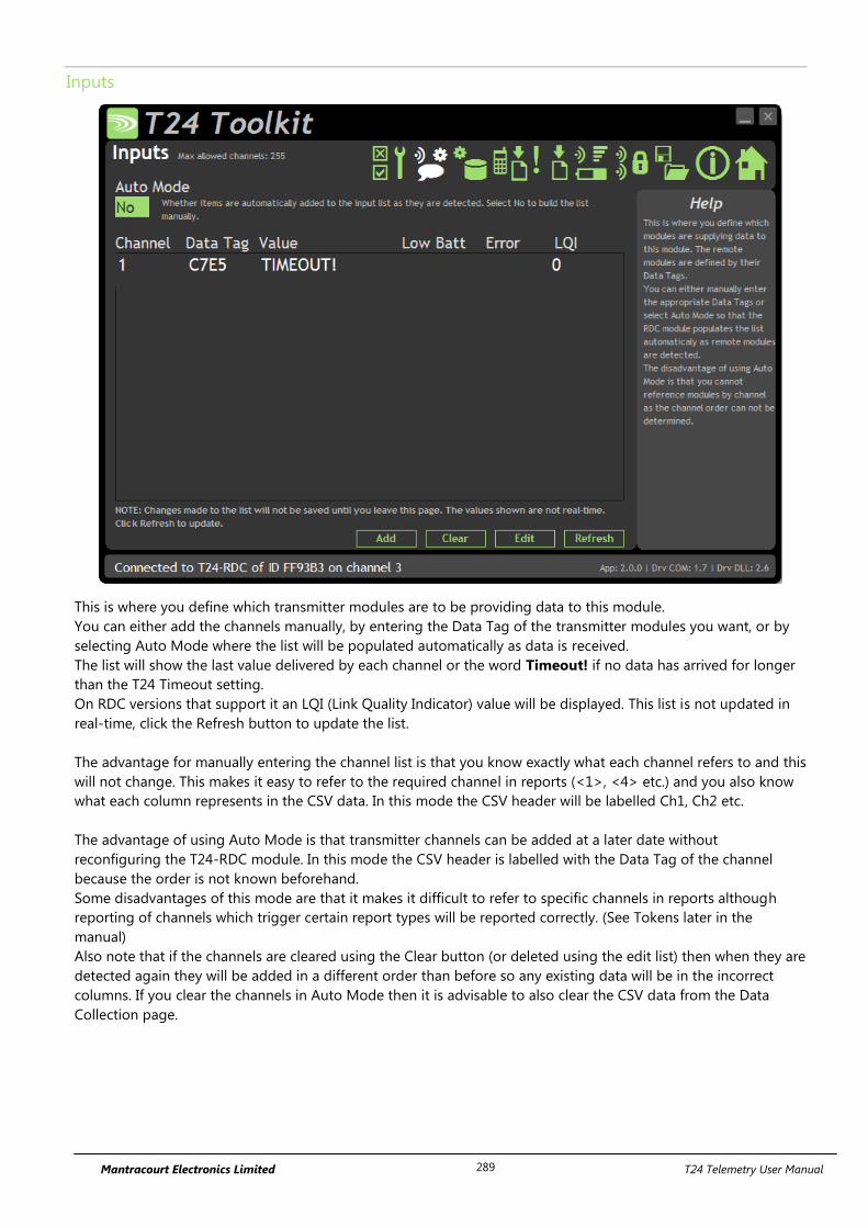
Mantracourt Electronics Limited T24 Telemetry User Manual 289
Inputs
This is where you define which transmitter modules are to be providing data to this module.
You can either add the channels manually, by entering the Data Tag of the transmitter modules you want, or by
selecting Auto Mode where the list will be populated automatically as data is received.
The list will show the last value delivered by each channel or the word Timeout! if no data has arrived for longer
than the T24 Timeout setting.
On RDC versions that support it an LQI (Link Quality Indicator) value will be displayed. This list is not updated in
real-time, click the Refresh button to update the list.
The advantage for manually entering the channel list is that you know exactly what each channel refers to and this
will not change. This makes it easy to refer to the required channel in reports (<1>, <4> etc.) and you also know
what each column represents in the CSV data. In this mode the CSV header will be labelled Ch1, Ch2 etc.
The advantage of using Auto Mode is that transmitter channels can be added at a later date without
reconfiguring the T24-RDC module. In this mode the CSV header is labelled with the Data Tag of the channel
because the order is not known beforehand.
Some disadvantages of this mode are that it makes it difficult to refer to specific channels in reports although
reporting of channels which trigger certain report types will be reported correctly. (See Tokens later in the
manual)
Also note that if the channels are cleared using the Clear button (or deleted using the edit list) then when they are
detected again they will be added in a different order than before so any existing data will be in the incorrect
columns. If you clear the channels in Auto Mode then it is advisable to also clear the CSV data from the Data
Collection page.

Mantracourt Electronics Limited T24 Telemetry User Manual 290
Items you can change:
Auto Mode Whether to automatically add channels.
Add Button Clicking this will allow you to specify a new Data Tag to add.
Clear Button This clears ALL the currently configured channels.
Edit Button Changes the display to show a simple list of Data Tags. This allows quick bulk
entry of tags from an external source. You can simply paste a list of tags into the
list or type them manually.
Refresh Button Refreshes the list.
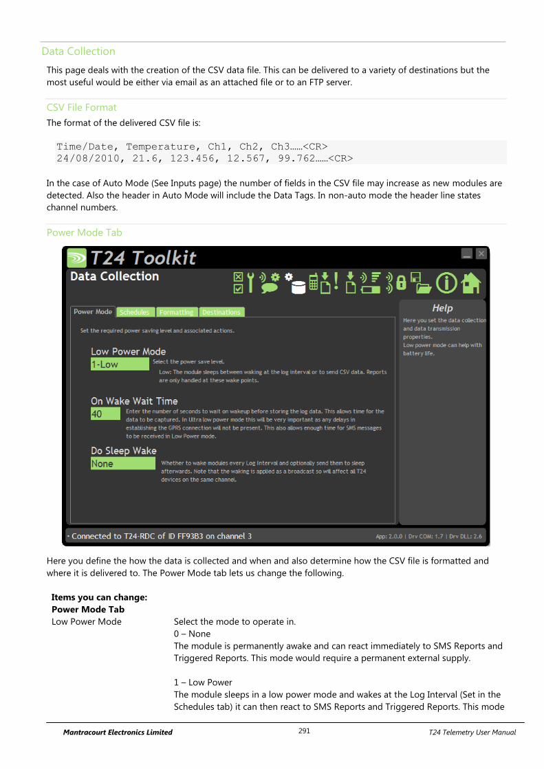
Mantracourt Electronics Limited T24 Telemetry User Manual 291
Data Collection
This page deals with the creation of the CSV data file. This can be delivered to a variety of destinations but the
most useful would be either via email as an attached file or to an FTP server.
CSV File Format
The format of the delivered CSV file is:
Time/Date, Temperature, Ch1, Ch2, Ch3……<CR>
24/08/2010, 21.6, 123.456, 12.567, 99.762……<CR>
In the case of Auto Mode (See Inputs page) the number of fields in the CSV file may increase as new modules are
detected. Also the header in Auto Mode will include the Data Tags. In non-auto mode the header line states
channel numbers.
Power Mode Tab
Here you define the how the data is collected and when and also determine how the CSV file is formatted and
where it is delivered to. The Power Mode tab lets us change the following.
Items you can change:
Power Mode Tab
Low Power Mode Select the mode to operate in.
0 – None
The module is permanently awake and can react immediately to SMS Reports and
Triggered Reports. This mode would require a permanent external supply.
1 – Low Power
The module sleeps in a low power mode and wakes at the Log Interval (Set in the
Schedules tab) it can then react to SMS Reports and Triggered Reports. This mode
Mantracourt Electronics Limited T24 Telemetry User Manual 292
is for battery powered external power.
2 – Ultra Low Power
This achieves the best external battery life of all the modes but the module can
only react to SMS Reports and Triggered Reports when the module wakes at the
CSV data transmission interval.
On Wake Wait Time This determines the minimum time (in seconds) the module remains awake at the
log or transmission intervals in Low or Ultra Low Power Mode.
In Ultra Low Power mode this should allow enough time for the module to
capture the data supplied by the transmitter modules so may be in the order of 5
to 10 seconds.
In Low Power Mode this may be increased to allow the module to process
incoming SMS triggers for SMS reports. On connecting to the cellular network it
may take up to 40 seconds or more for the network to send the module any
stored SMS messages. This should always be less than the Log Interval time.
Do Sleep Wake Only used in Low Power Mode.
Determines whether the module will wake transmitter modules when it wakes up
itself.
You can also select whether the RDC sends the modules back to sleep after a
reading has been recorded.
It is advisable to also set a Sleep Delay on the transmitter
modules and not rely solely on the RDC to send the modules
to sleep.
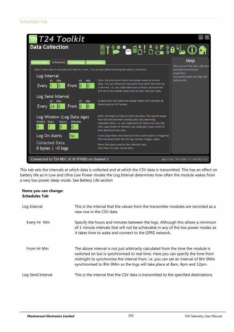
Mantracourt Electronics Limited T24 Telemetry User Manual 293
Schedules Tab
This tab sets the intervals at which data is collected and at which the CSV data is transmitted. This has an effect on
battery life as in Low and Ultra Low Power modes the Log Interval determines how often the module wakes from
a very low power sleep mode. See Battery Life section
Items you can change:
Schedules Tab
Log Interval This is the interval that the values from the transmitter modules are recorded as a
new row in the CSV data.
Every Hr Min Specify the hours and minutes between the logs. Although this allows a minimum
of 1 minute intervals that will not be achievable in any of the low power modes as
it takes time to wake and connect to the GPRS network.
From Hr Min The above interval is not just arbitrarily calculated from the time the module is
switched on but is synchronised to real time. Here you can specify the time from
midnight to synchronise the interval from. i.e. you can set an interval of 8Hr 0Min
synchronised to 8Hr 0Min so the logs will take place at 8am, 4pm and 12pm.
Log Send Interval This is the interval that the CSV data is transmitted to the specified destinations.
Mantracourt Electronics Limited T24 Telemetry User Manual 294
Every Hr Min Specify the hours and minutes between the transmissions. This is not
recommended to be less than around 5 minutes. Also note that the size of the
CSV data that is sent, the number of destinations and other reports may take
more time than the interval specified here. i.e. there may be a minimum log send
interval that you can use depending on other settings. The RDC has not been
designed for high speed transmission of data.
From Hr Min The above interval is not just arbitrarily calculated from the time the module is
switched on but is synchronised to real time. Here you can specify the time from
midnight to synchronise the interval from. i.e. you can set an interval of 6Hr 0Min
synchronised to 6Hr 0Min so the logs will take place at 6am, 12am, 6pm and
12pm.
Log Window Here you can specify how much data the CSV file contains. As new data is added
at the log interval any data older than the age set here will be deleted.
By adjusting this time you can dramatically alter the delivered data. i.e. with a CSV
data delivery daily you could use a window of 1 day so that each delivery contains
all logged data since the last delivery. By doubling the window you could deliver 2
days’ worth of data daily. This would protect against one delivery failing due to
network unavailability for example.
By setting the window to zero or less than the log interval you would deliver one
line containing just the last data gathered from the transmitter modules.
Log On Alerts If this option is chosen then a log will take place every time a triggered report
based on the value from an input module is triggered. (i.e. greater or less than a
user defined limit).
This ensures that the CSV data contains the value that caused the report to
trigger.
The user of the CSV file must use the date/time stamp to determine when the data was
logged and not just assume it was logged at the Log Interval!
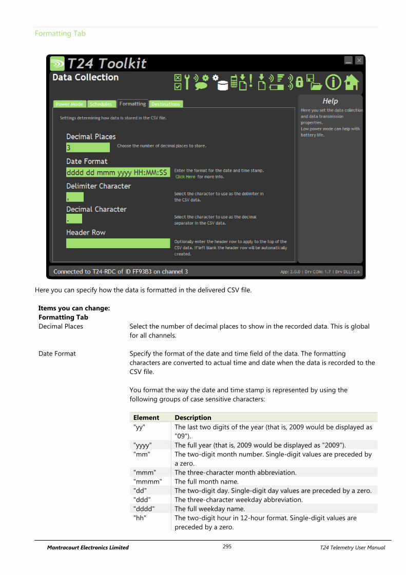
Mantracourt Electronics Limited T24 Telemetry User Manual 295
Formatting Tab
Here you can specify how the data is formatted in the delivered CSV file.
Items you can change:
Formatting Tab
Decimal Places Select the number of decimal places to show in the recorded data. This is global
for all channels.
Date Format Specify the format of the date and time field of the data. The formatting
characters are converted to actual time and date when the data is recorded to the
CSV file.
You format the way the date and time stamp is represented by using the
following groups of case sensitive characters:
Element Description
"yy" The last two digits of the year (that is, 2009 would be displayed as
"09").
"yyyy" The full year (that is, 2009 would be displayed as "2009").
"mm" The two-digit month number. Single-digit values are preceded by
a zero.
"mmm" The three-character month abbreviation.
"mmmm" The full month name.
"dd" The two-digit day. Single-digit day values are preceded by a zero.
"ddd" The three-character weekday abbreviation.
"dddd" The full weekday name.
"hh" The two-digit hour in 12-hour format. Single-digit values are
preceded by a zero.
Mantracourt Electronics Limited T24 Telemetry User Manual 296
"HH" The two-digit hour in 24-hour format. Single-digit values are
preceded by a zero.
"MM" The two-digit minute. Single-digit values are preceded by a zero.
"SS" The two-digit second. Single-digit values are preceded by a zero.
"TT" The two-letter AM/PM abbreviation (that is, AM is displayed as
"AM").
"ee" The full time and date encoded numerically in the MS Excel
format.
"EE" Epoch format in milliseconds elapsed since 01/01/1970.
Any other characters will form part of the formatted output.
i.e.
‘mmmm dd yyyy at HH:MM:SS’
would decode to
‘January 15 2009 at 12:23:05’
Delimiter Character Specify the character used between the values. Usually the UK setting would be a
comma but some countries use a semi-colon.
Decimal Character Specify the decimal separator. Usually in the UK this would be a decimal point but
Europe would use a comma.
Header Row You can override the automatic header row at the top of the CSV file by entering
a custom one here.
i.e. Date,IntTemp,Strut1,Strut2,ExtTemp
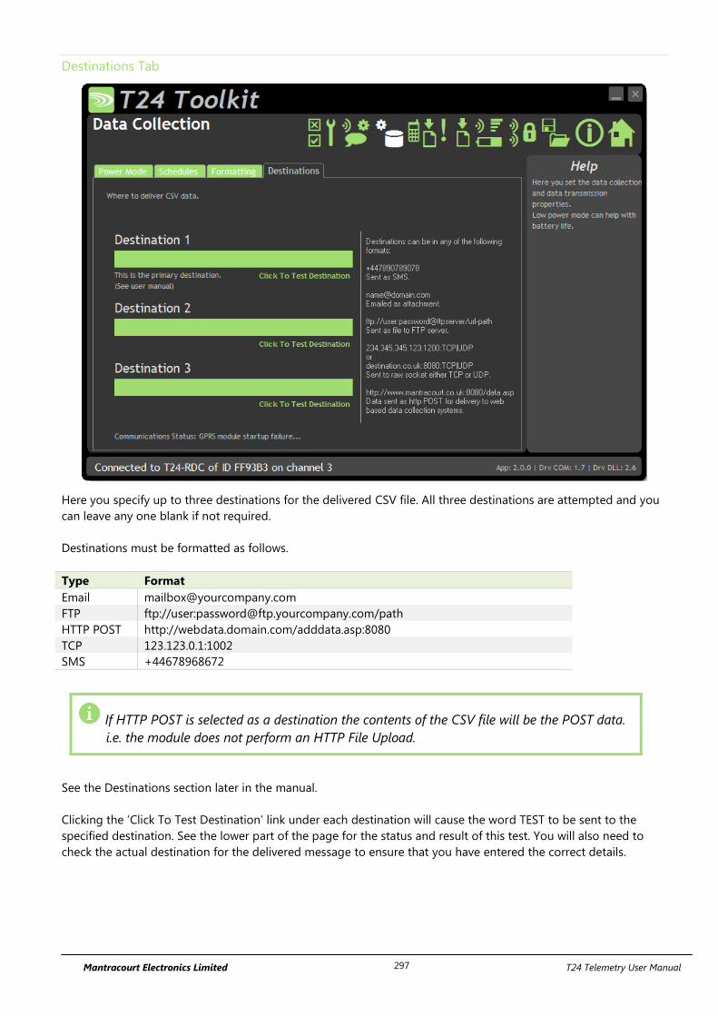
Mantracourt Electronics Limited T24 Telemetry User Manual 297
Destinations Tab
Here you specify up to three destinations for the delivered CSV file. All three destinations are attempted and you
can leave any one blank if not required.
Destinations must be formatted as follows.
Type Format
Email [email protected]
FTP ftp://user:[email protected]/path
HTTP POST http://webdata.domain.com/adddata.asp:8080
TCP 123.123.0.1:1002
SMS +44678968672
If HTTP POST is selected as a destination the contents of the CSV file will be the POST data.
i.e. the module does not perform an HTTP File Upload.
See the Destinations section later in the manual.
Clicking the ‘Click To Test Destination’ link under each destination will cause the word TEST to be sent to the
specified destination. See the lower part of the page for the status and result of this test. You will also need to
check the actual destination for the delivered message to ensure that you have entered the correct details.

Mantracourt Electronics Limited T24 Telemetry User Manual 298
Items you can change:
Destinations Tab
Destination 1 Enter the required destination. NOTE that this is the primary destination and if in
Low Power mode and this delivery fails it will be retried at every subsequent Log
Interval.
Destination 2 Enter the required destination.
Destination 3 Enter the required destination.
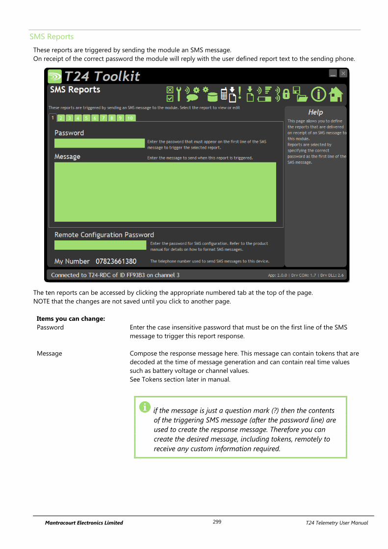
Mantracourt Electronics Limited T24 Telemetry User Manual 299
SMS Reports
These reports are triggered by sending the module an SMS message.
On receipt of the correct password the module will reply with the user defined report text to the sending phone.
The ten reports can be accessed by clicking the appropriate numbered tab at the top of the page.
NOTE that the changes are not saved until you click to another page.
Items you can change:
Password Enter the case insensitive password that must be on the first line of the SMS
message to trigger this report response.
Message Compose the response message here. This message can contain tokens that are
decoded at the time of message generation and can contain real time values
such as battery voltage or channel values.
See Tokens section later in manual.
if the message is just a question mark (?) then the contents
of the triggering SMS message (after the password line) are
used to create the response message. Therefore you can
create the desired message, including tokens, remotely to
receive any custom information required.
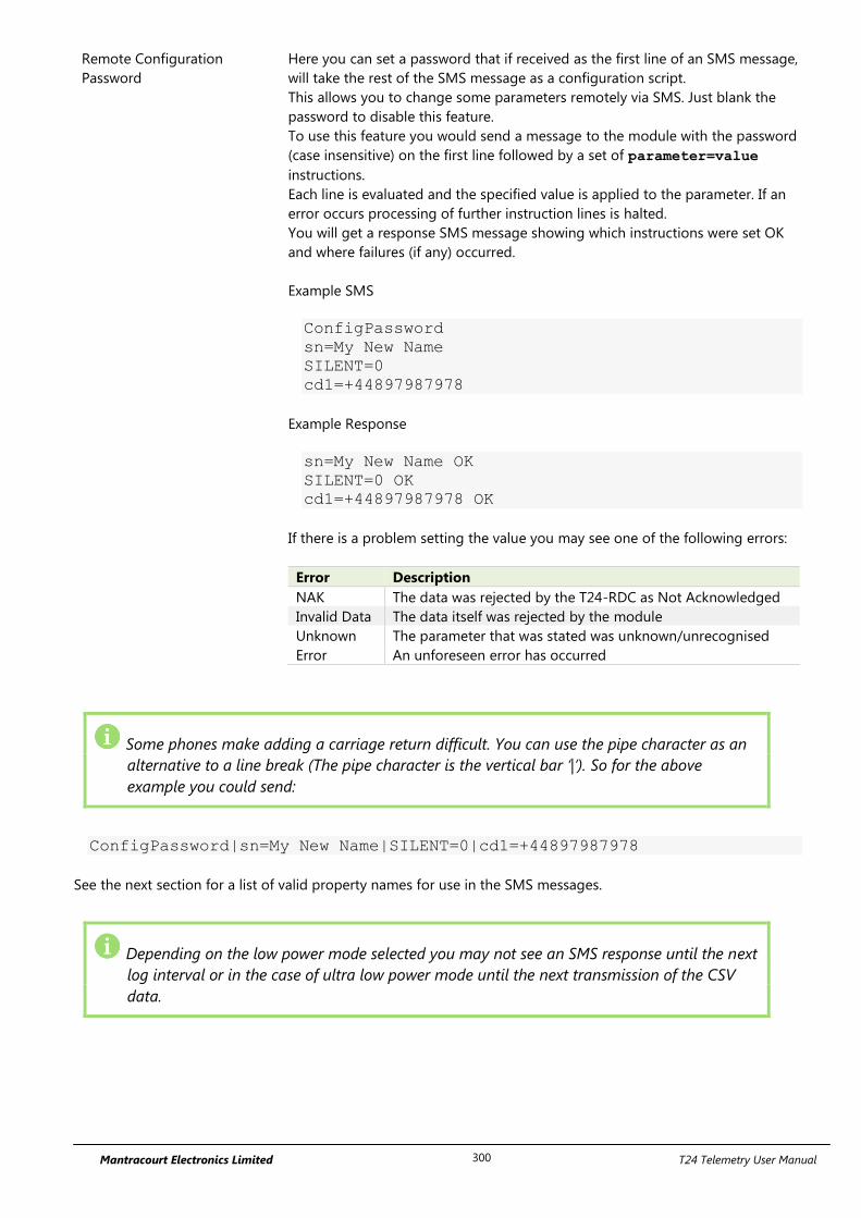
Mantracourt Electronics Limited T24 Telemetry User Manual 300
Remote Configuration
Password
Here you can set a password that if received as the first line of an SMS message,
will take the rest of the SMS message as a configuration script.
This allows you to change some parameters remotely via SMS. Just blank the
password to disable this feature.
To use this feature you would send a message to the module with the password
(case insensitive) on the first line followed by a set of parameter=value
instructions.
Each line is evaluated and the specified value is applied to the parameter. If an
error occurs processing of further instruction lines is halted.
You will get a response SMS message showing which instructions were set OK
and where failures (if any) occurred.
Example SMS
ConfigPassword
sn=My New Name
SILENT=0
cd1=+44897987978
Example Response
sn=My New Name OK
SILENT=0 OK
cd1=+44897987978 OK
If there is a problem setting the value you may see one of the following errors:
Error Description
NAK The data was rejected by the T24-RDC as Not Acknowledged
Invalid Data The data itself was rejected by the module
Unknown The parameter that was stated was unknown/unrecognised
Error An unforeseen error has occurred
Some phones make adding a carriage return difficult. You can use the pipe character as an
alternative to a line break (The pipe character is the vertical bar ‘|’). So for the above
example you could send:
ConfigPassword|sn=My New Name|SILENT=0|cd1=+44897987978
See the next section for a list of valid property names for use in the SMS messages.
Depending on the low power mode selected you may not see an SMS response until the next
log interval or in the case of ultra low power mode until the next transmission of the CSV
data.
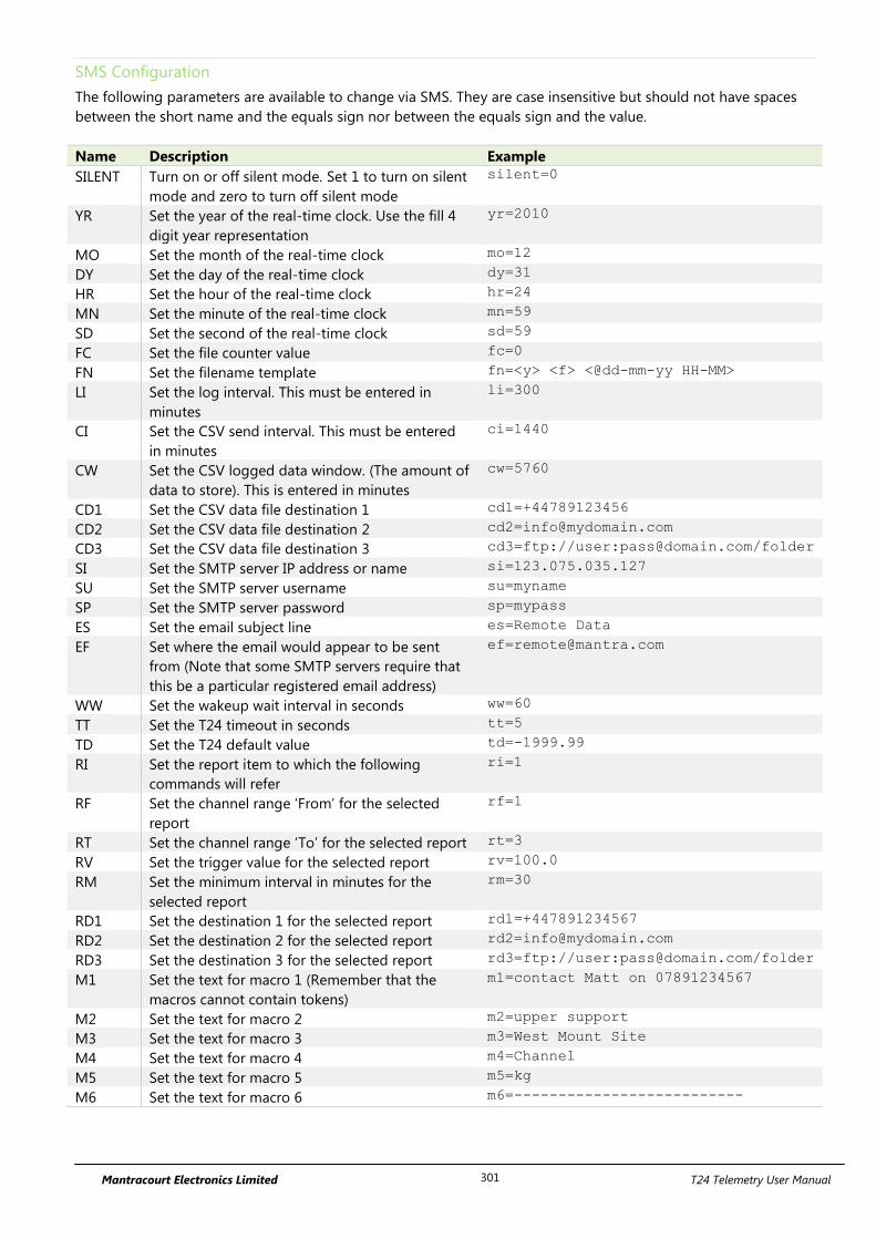
Mantracourt Electronics Limited T24 Telemetry User Manual 301
SMS Configuration
The following parameters are available to change via SMS. They are case insensitive but should not have spaces
between the short name and the equals sign nor between the equals sign and the value.
Name Description Example
SILENT Turn on or off silent mode. Set 1 to turn on silent
mode and zero to turn off silent mode
silent=0
YR Set the year of the real-time clock. Use the fill 4
digit year representation
yr=2010
MO Set the month of the real-time clock mo=12
DY Set the day of the real-time clock dy=31
HR Set the hour of the real-time clock hr=24
MN Set the minute of the real-time clock mn=59
SD Set the second of the real-time clock sd=59
FC Set the file counter value fc=0
FN Set the filename template fn=<y> <f> <@dd-mm-yy HH-MM>
LI Set the log interval. This must be entered in
minutes
li=300
CI Set the CSV send interval. This must be entered
in minutes
ci=1440
CW Set the CSV logged data window. (The amount of
data to store). This is entered in minutes
cw=5760
CD1 Set the CSV data file destination 1 cd1=+44789123456
CD2 Set the CSV data file destination 2 [email protected]
CD3 Set the CSV data file destination 3 cd3=ftp://user:[email protected]/folder
SI Set the SMTP server IP address or name si=123.075.035.127
SU Set the SMTP server username su=myname
SP Set the SMTP server password sp=mypass
ES Set the email subject line es=Remote Data
EF Set where the email would appear to be sent
from (Note that some SMTP servers require that
this be a particular registered email address)
WW Set the wakeup wait interval in seconds ww=60
TT Set the T24 timeout in seconds tt=5
TD Set the T24 default value td=-1999.99
RI Set the report item to which the following
commands will refer
ri=1
RF Set the channel range ‘From’ for the selected
report
rf=1
RT Set the channel range ‘To’ for the selected report rt=3
RV Set the trigger value for the selected report rv=100.0
RM Set the minimum interval in minutes for the
selected report
rm=30
RD1 Set the destination 1 for the selected report rd1=+447891234567
RD2 Set the destination 2 for the selected report [email protected]
RD3 Set the destination 3 for the selected report rd3=ftp://user:[email protected]/folder
M1 Set the text for macro 1 (Remember that the
macros cannot contain tokens)
m1=contact Matt on 07891234567
M2 Set the text for macro 2 m2=upper support
M3 Set the text for macro 3 m3=West Mount Site
M4 Set the text for macro 4 m4=Channel
M5 Set the text for macro 5 m5=kg
M6 Set the text for macro 6 m6=--------------------------
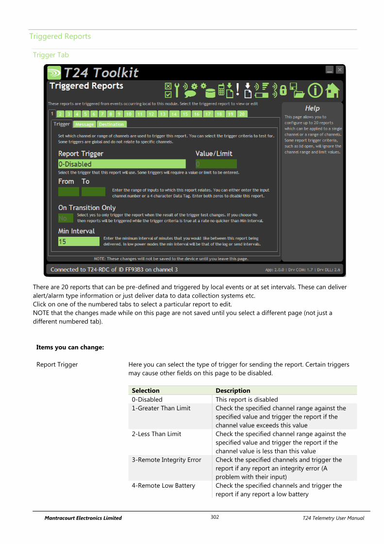
Mantracourt Electronics Limited T24 Telemetry User Manual 302
Triggered Reports
Trigger Tab
There are 20 reports that can be pre-defined and triggered by local events or at set intervals. These can deliver
alert/alarm type information or just deliver data to data collection systems etc.
Click on one of the numbered tabs to select a particular report to edit.
NOTE that the changes made while on this page are not saved until you select a different page (not just a
different numbered tab).
Items you can change:
Report Trigger Here you can select the type of trigger for sending the report. Certain triggers
may cause other fields on this page to be disabled.
Selection Description
0-Disabled This report is disabled
1-Greater Than Limit Check the specified channel range against the
specified value and trigger the report if the
channel value exceeds this value
2-Less Than Limit Check the specified channel range against the
specified value and trigger the report if the
channel value is less than this value
3-Remote Integrity Error Check the specified channels and trigger the
report if any report an integrity error (A
problem with their input)
4-Remote Low Battery Check the specified channels and trigger the
report if any report a low battery
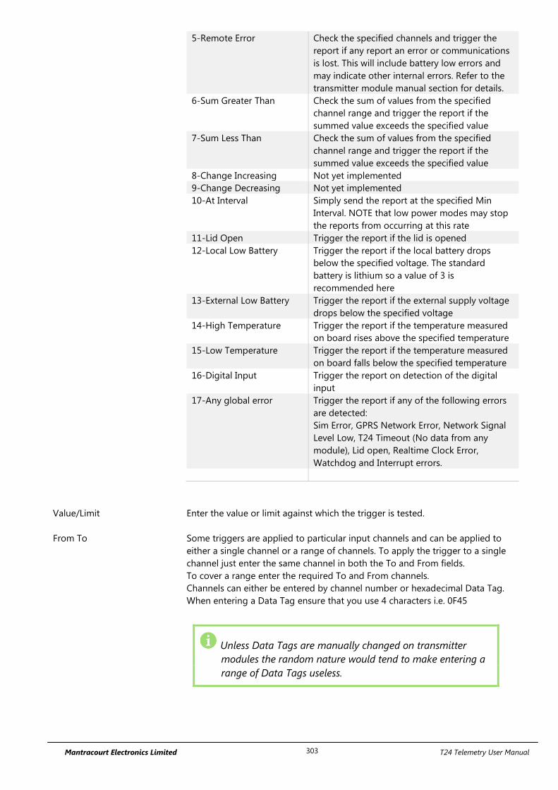
Mantracourt Electronics Limited T24 Telemetry User Manual 303
5-Remote Error Check the specified channels and trigger the
report if any report an error or communications
is lost. This will include battery low errors and
may indicate other internal errors. Refer to the
transmitter module manual section for details.
6-Sum Greater Than Check the sum of values from the specified
channel range and trigger the report if the
summed value exceeds the specified value
7-Sum Less Than Check the sum of values from the specified
channel range and trigger the report if the
summed value exceeds the specified value
8-Change Increasing Not yet implemented
9-Change Decreasing Not yet implemented
10-At Interval Simply send the report at the specified Min
Interval. NOTE that low power modes may stop
the reports from occurring at this rate
11-Lid Open Trigger the report if the lid is opened
12-Local Low Battery Trigger the report if the local battery drops
below the specified voltage. The standard
battery is lithium so a value of 3 is
recommended here
13-External Low Battery Trigger the report if the external supply voltage
drops below the specified voltage
14-High Temperature Trigger the report if the temperature measured
on board rises above the specified temperature
15-Low Temperature Trigger the report if the temperature measured
on board falls below the specified temperature
16-Digital Input Trigger the report on detection of the digital
input
17-Any global error Trigger the report if any of the following errors
are detected:
Sim Error, GPRS Network Error, Network Signal
Level Low, T24 Timeout (No data from any
module), Lid open, Realtime Clock Error,
Watchdog and Interrupt errors.
Value/Limit Enter the value or limit against which the trigger is tested.
From To Some triggers are applied to particular input channels and can be applied to
either a single channel or a range of channels. To apply the trigger to a single
channel just enter the same channel in both the To and From fields.
To cover a range enter the required To and From channels.
Channels can either be entered by channel number or hexadecimal Data Tag.
When entering a Data Tag ensure that you use 4 characters i.e. 0F45
Unless Data Tags are manually changed on transmitter
modules the random nature would tend to make entering a
range of Data Tags useless.

Mantracourt Electronics Limited T24 Telemetry User Manual 304
On transition Only Here you can decide whether the reports are sent all the time the trigger result
is true or only on a change of the result.
i.e. if the trigger is a low battery and the transition setting is NO then the report
will be sent at every Min Interval (Assuming not in low power mode) while the
battery is low.
If the transition setting is YES then the report will be sent once the battery
becomes low and again when it is no longer low. The min interval still applies.
Min Interval This is the minimum interval in minutes between deliveries of the report. The
minimum number you can enter is 1.
Unlike the data log and CSV send intervals these intervals are not tied to
absolute time but are timed from the last sending of the report.
Also bear in mind that in Low Power or Ultra Low Power modes reports could
not be delivered more regularly than the Log Interval or the CSV Delivery
Interval respectively.
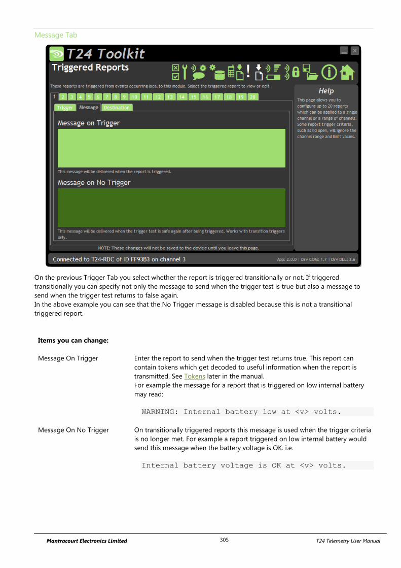
Mantracourt Electronics Limited T24 Telemetry User Manual 305
Message Tab
On the previous Trigger Tab you select whether the report is triggered transitionally or not. If triggered
transitionally you can specify not only the message to send when the trigger test is true but also a message to
send when the trigger test returns to false again.
In the above example you can see that the No Trigger message is disabled because this is not a transitional
triggered report.
Items you can change:
Message On Trigger Enter the report to send when the trigger test returns true. This report can
contain tokens which get decoded to useful information when the report is
transmitted. See Tokens later in the manual.
For example the message for a report that is triggered on low internal battery
may read:
WARNING: Internal battery low at <v> volts.
Message On No Trigger On transitionally triggered reports this message is used when the trigger criteria
is no longer met. For example a report triggered on low internal battery would
send this message when the battery voltage is OK. i.e.
Internal battery voltage is OK at <v> volts.
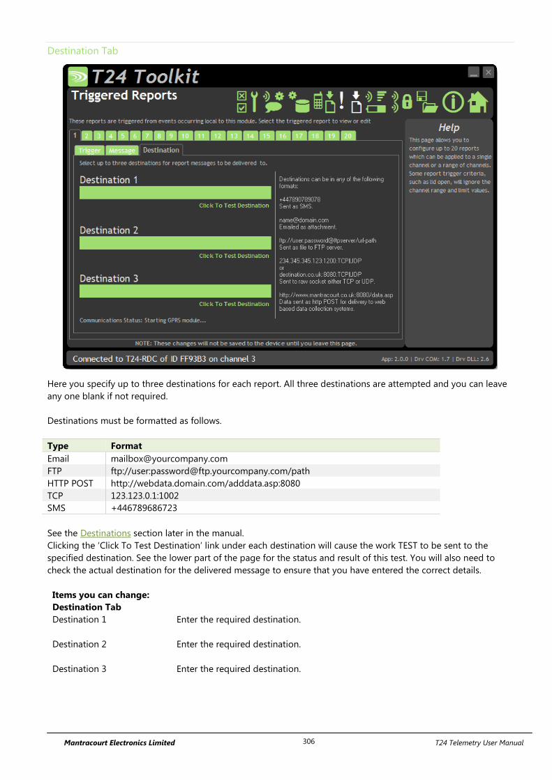
Mantracourt Electronics Limited T24 Telemetry User Manual 306
Destination Tab
Here you specify up to three destinations for each report. All three destinations are attempted and you can leave
any one blank if not required.
Destinations must be formatted as follows.
Type Format
Email [email protected]
FTP ftp://user:[email protected]/path
HTTP POST http://webdata.domain.com/adddata.asp:8080
TCP 123.123.0.1:1002
SMS +446789686723
See the Destinations section later in the manual.
Clicking the ‘Click To Test Destination’ link under each destination will cause the work TEST to be sent to the
specified destination. See the lower part of the page for the status and result of this test. You will also need to
check the actual destination for the delivered message to ensure that you have entered the correct details.
Items you can change:
Destination Tab
Destination 1 Enter the required destination.
Destination 2 Enter the required destination.
Destination 3 Enter the required destination.
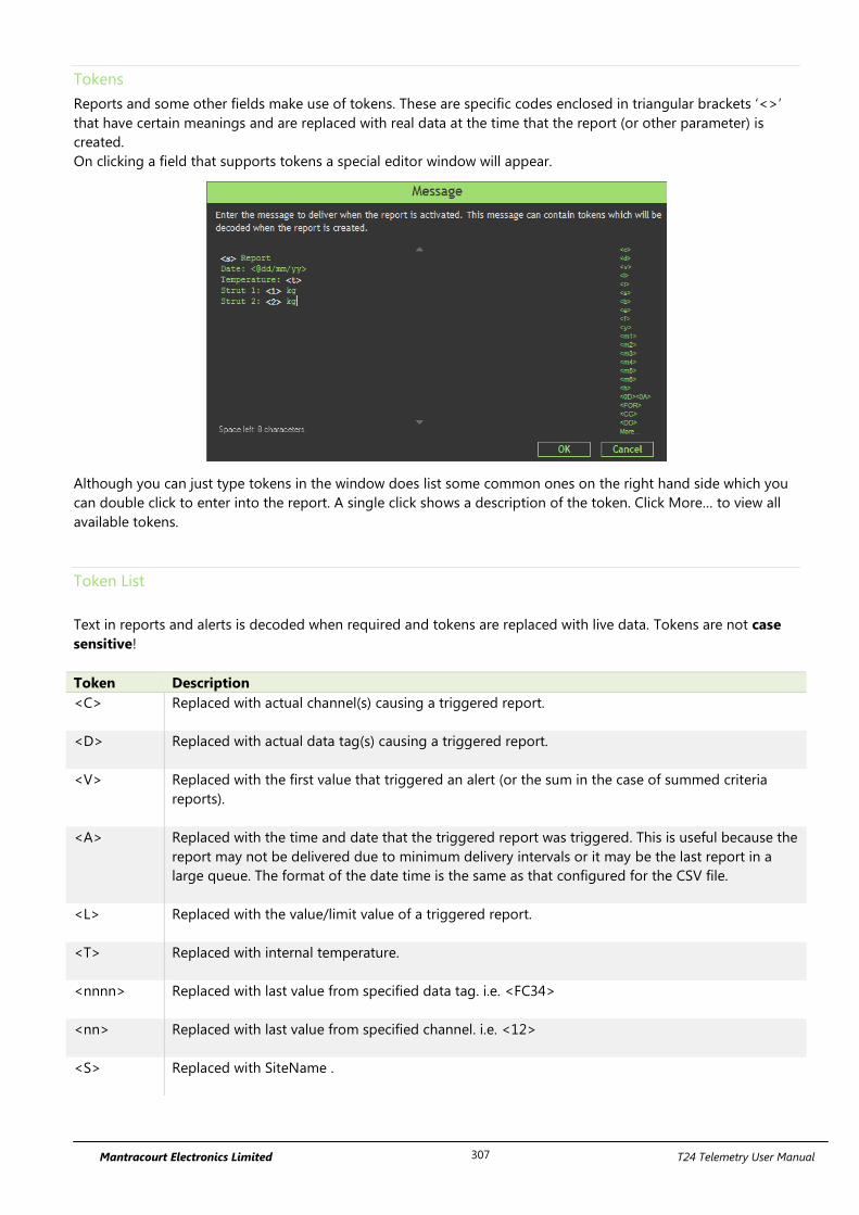
Mantracourt Electronics Limited T24 Telemetry User Manual 307
Tokens
Reports and some other fields make use of tokens. These are specific codes enclosed in triangular brackets ‘<>’
that have certain meanings and are replaced with real data at the time that the report (or other parameter) is
created.
On clicking a field that supports tokens a special editor window will appear.
Although you can just type tokens in the window does list some common ones on the right hand side which you
can double click to enter into the report. A single click shows a description of the token. Click More… to view all
available tokens.
Token List
Text in reports and alerts is decoded when required and tokens are replaced with live data. Tokens are not case
sensitive!
Token Description
<C> Replaced with actual channel(s) causing a triggered report.
<D> Replaced with actual data tag(s) causing a triggered report.
<V> Replaced with the first value that triggered an alert (or the sum in the case of summed criteria
reports).
<A> Replaced with the time and date that the triggered report was triggered. This is useful because the
report may not be delivered due to minimum delivery intervals or it may be the last report in a
large queue. The format of the date time is the same as that configured for the CSV file.
<L> Replaced with the value/limit value of a triggered report.
<T> Replaced with internal temperature.
<nnnn> Replaced with last value from specified data tag. i.e. <FC34>
<nn> Replaced with last value from specified channel. i.e. <12>
<S> Replaced with SiteName .
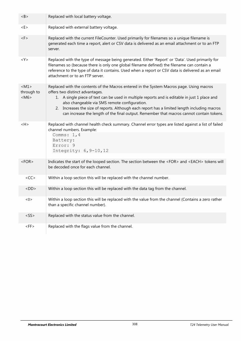
Mantracourt Electronics Limited T24 Telemetry User Manual 308
<B> Replaced with local battery voltage.
<E> Replaced with external battery voltage.
<F> Replaced with the current FileCounter. Used primarily for filenames so a unique filename is
generated each time a report, alert or CSV data is delivered as an email attachment or to an FTP
server.
<Y> Replaced with the type of message being generated. Either ‘Report’ or ‘Data’. Used primarily for
filenames so (because there is only one global filename defined) the filename can contain a
reference to the type of data it contains. Used when a report or CSV data is delivered as an email
attachment or to an FTP server.
<M1>
through to
<M6>
Replaced with the contents of the Macros entered in the System Macros page. Using macros
offers two distinct advantages.
1. A single piece of text can be used in multiple reports and is editable in just 1 place and
also changeable via SMS remote configuration.
2. Increases the size of reports. Although each report has a limited length including macros
can increase the length of the final output. Remember that macros cannot contain tokens.
<H> Replaced with channel health check summary. Channel error types are listed against a list of failed
channel numbers. Example:
Comms: 1,4
Battery:
Error: 9
Integrity: 6,9-10,12
<FOR> Indicates the start of the looped section. The section between the <FOR> and <EACH> tokens will
be decoded once for each channel.
<CC> Within a loop section this will be replaced with the channel number.
<DD> Within a loop section this will be replaced with the data tag from the channel.
<0> Within a loop section this will be replaced with the value from the channel (Contains a zero rather
than a specific channel number).
<SS> Replaced with the status value from the channel.
<FF> Replaced with the flags value from the channel.
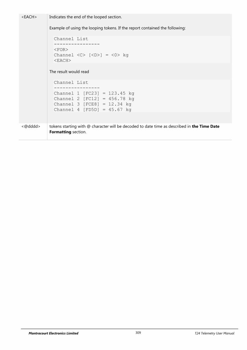
Mantracourt Electronics Limited T24 Telemetry User Manual 309
<EACH> Indicates the end of the looped section.
Example of using the looping tokens. If the report contained the following:
Channel List
----------------
<FOR>
Channel <C> [<D>] = <0> kg
<EACH>
The result would read
Channel List
----------------
Channel 1 [FC23] = 123.45 kg
Channel 2 [FC12] = 456.78 kg
Channel 3 [FCE8] = 12.34 kg
Channel 4 [FD5D] = 45.67 kg
<@dddd> tokens starting with @ character will be decoded to date time as described in the Time Date
Formatting section.
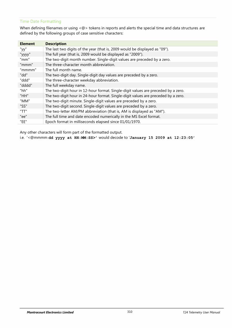
Mantracourt Electronics Limited T24 Telemetry User Manual 310
Time Date Formatting
When defining filenames or using <@> tokens in reports and alerts the special time and data structures are
defined by the following groups of case sensitive characters:
Element Description
"yy" The last two digits of the year (that is, 2009 would be displayed as "09").
"yyyy" The full year (that is, 2009 would be displayed as "2009").
"mm" The two-digit month number. Single-digit values are preceded by a zero.
"mmm" The three-character month abbreviation.
"mmmm" The full month name.
"dd" The two-digit day. Single-digit day values are preceded by a zero.
"ddd" The three-character weekday abbreviation.
"dddd" The full weekday name.
"hh" The two-digit hour in 12-hour format. Single-digit values are preceded by a zero.
"HH" The two-digit hour in 24-hour format. Single-digit values are preceded by a zero.
"MM" The two-digit minute. Single-digit values are preceded by a zero.
"SS" The two-digit second. Single-digit values are preceded by a zero.
"TT" The two-letter AM/PM abbreviation (that is, AM is displayed as "AM").
"ee" The full time and date encoded numerically in the MS Excel format.
"EE" Epoch format in milliseconds elapsed since 01/01/1970.
Any other characters will form part of the formatted output.
i.e. ‘<@mmmm dd yyyy at HH:MM:SS>’ would decode to ‘January 15 2009 at 12:23:05’
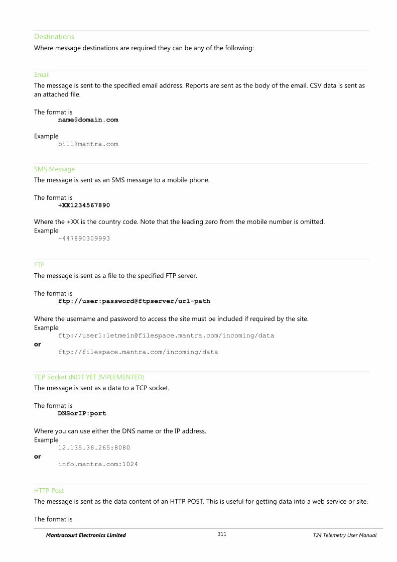
Mantracourt Electronics Limited T24 Telemetry User Manual 311
Destinations
Where message destinations are required they can be any of the following:
The message is sent to the specified email address. Reports are sent as the body of the email. CSV data is sent as
an attached file.
The format is [email protected]
Example [email protected]
SMS Message
The message is sent as an SMS message to a mobile phone.
The format is +XX1234567890
Where the +XX is the country code. Note that the leading zero from the mobile number is omitted.
Example +447890309993
FTP
The message is sent as a file to the specified FTP server.
The format is ftp://user:password@ftpserver/url-path
Where the username and password to access the site must be included if required by the site.
Example ftp://user1:[email protected]/incoming/data
or ftp://filespace.mantra.com/incoming/data
TCP Socket (NOT YET IMPLEMENTED)
The message is sent as a data to a TCP socket.
The format is DNSorIP:port
Where you can use either the DNS name or the IP address.
Example 12.135.36.265:8080
or info.mantra.com:1024
HTTP Post
The message is sent as the data content of an HTTP POST. This is useful for getting data into a web service or site.
The format is
Mantracourt Electronics Limited T24 Telemetry User Manual 312
http://domain:port/path
Where you can use either the DNS name or the IP address.
Example http://mantra.com:80/cgi-bin
or http://mantra.com/adddata.asp
As this posts data the same way as does submitting data from forms in web pages etc. it is very easy to handle
data delivered by this method into web sites and data collection systems. Design your message to just contain
the parameters and values. i.e.
V1=<1>&V2=<2>&DATESTAMP=<@ddmmyyyy>
The module wraps up the other required header text to deliver the POST to the destination.
As an example if the destination was
http://host.com/Service/batch
and your report message was
V1=<1>&V2=<2>&DATESTAMP=<@ddmmyyyy>
The actual delivered data would be
POST http://host.com/Service/batch HTTP/1.0
Host: host.com
Content-Type: application/x-www-form-urlencoded
Content-Length: 40
V1=123.456&V2=456.789&DATESTAMP=31122010
Now the receiving destination just needs to deal with the parameters. For example if you delivered the above
data to an ASP page URL then you can extract the data as follows
X = Request.Form("V1")
Y = Request.Form("V2")
Z = Request.Form("DATESTAMP")
Custom Headers
You can add custom lines to the header (See System page POST) which will allow authorization details and other
security information to be added to the HTTP header if the site you are posting data to requires it.
POST http://host.com/Service/batch HTTP/1.0
Host: host.com
Content-Type: application/x-www-form-urlencoded
CUSTOM HEADER ITEMS APPEAR HERE
Content-Length: 40
V1=123.456&V2=456.789&DATESTAMP=31122010
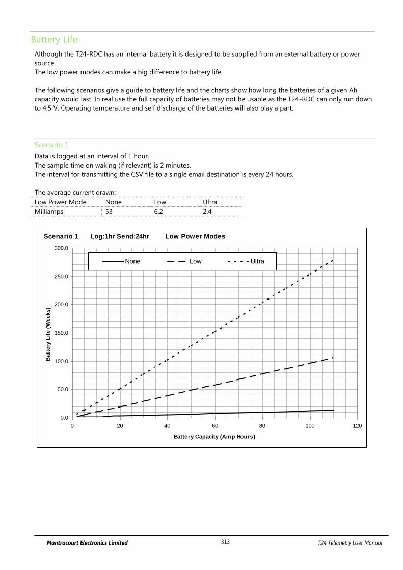
Mantracourt Electronics Limited T24 Telemetry User Manual 313
Battery Life
Although the T24-RDC has an internal battery it is designed to be supplied from an external battery or power
source.
The low power modes can make a big difference to battery life.
The following scenarios give a guide to battery life and the charts show how long the batteries of a given Ah
capacity would last. In real use the full capacity of batteries may not be usable as the T24-RDC can only run down
to 4.5 V. Operating temperature and self discharge of the batteries will also play a part.
Scenario 1
Data is logged at an interval of 1 hour.
The sample time on waking (if relevant) is 2 minutes.
The interval for transmitting the CSV file to a single email destination is every 24 hours.
The average current drawn:
Low Power Mode None Low Ultra
Milliamps 53 6.2 2.4
Scenario 1 Log:1hr Send:24hr Low Power Modes
0.0
50.0
100.0
150.0
200.0
250.0
300.0
0 20 40 60 80 100 120
Battery Capacity (Amp Hours)
Batt
ery
Lif
e (
Weeks)
None Low Ultra
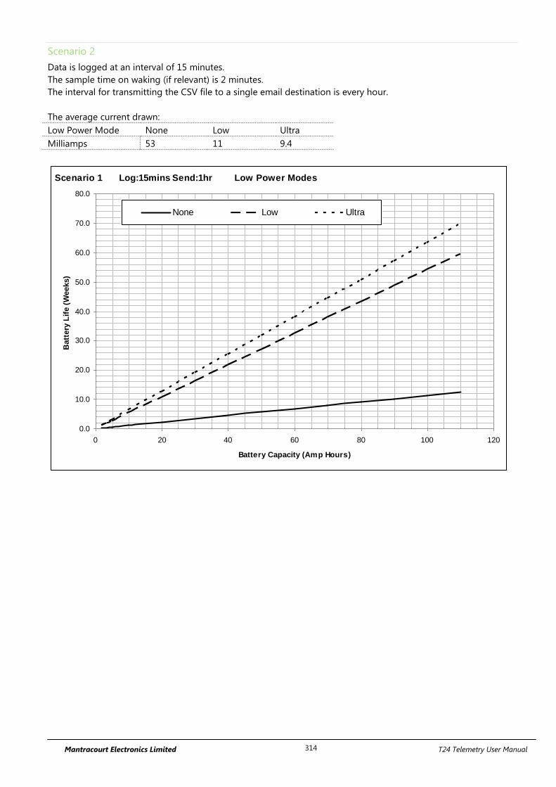
Mantracourt Electronics Limited T24 Telemetry User Manual 314
Scenario 2
Data is logged at an interval of 15 minutes.
The sample time on waking (if relevant) is 2 minutes.
The interval for transmitting the CSV file to a single email destination is every hour.
The average current drawn:
Low Power Mode None Low Ultra
Milliamps 53 11 9.4
Scenario 1 Log:15mins Send:1hr Low Power Modes
0.0
10.0
20.0
30.0
40.0
50.0
60.0
70.0
80.0
0 20 40 60 80 100 120
Battery Capacity (Amp Hours)
Batt
ery
Lif
e (
Weeks)
None Low Ultra
Mantracourt Electronics Limited T24 Telemetry User Manual 315
SIM Card Considerations
SIM Requirement
SIM must be able to support host having only a 2G connection to the cellular network!
Key Tariff Features:
Internet Usage Costs
o PAYG usually higher cost than contract per MB
o Contract Included in monthly allowance
o Fair Usage Allowance (5MB / day)
SMS Allowance
o Depending on Reports
Call Credit
o The T24-RDC does not require any air time minutes
Robustness
o Consider dedicated M2M SIM module contracts designed for machine to machine
communications
Pay As You Go SIM
Top Up as you require must register for online top-up before sending out module
Alternatively Direct Debit Top up when credit goes below £5
Higher internet usage charges
Lower Internet Usage Allowance / Fair Usage
SIM card must be registered or network access is limited
Some PAYG SIMS in some countries may prove less reliable than contract SIMs
Large incoming text messages from providers can in some cases cause module freezes
Cannot tell when credit runs out other than a break in service
Only recommended for testing purposes as the stability of these SIMs is not robust
enough for remote deployment.
Contract SIM
Constant Cost when SIM card not in use with T24-RDC
Higher quality of service
Only recommended for testing purposes as the stability of these SIMs is not robust
enough for remote deployment.
M2M Dedicated SIM
Very robust
Designed for use with machine to machine communications
Voice data not required
This is the recommended SIM type for use in the T24-RDC modules.
Mantracourt Electronics Limited T24 Telemetry User Manual 316
Service Provider Settings for T24-RDC
Access Point Name (APN)
Effectively the service provider website portal to give access to the internet
User Name & Password
These are provided to give you access to the internet, the same provider may have different usernames
and passwords for PAYG vs Contract customers to distinguish users.
Mantracourt Electronics Limited T24 Telemetry User Manual 317
Service Providers
All service providers have different coverage, the below website allows you to check service providers coverage
using your postcode as the reference location.
http://www.gadgetstylist.com/blog/mobile-phone-coverage-check-your-mobile-coverage/
The same network may get access to different types of internet connection, GPRS, Edge, 3G, HSDPA (High speed
Downlink Packet Access) depending on location. The key difference between all these connection types is speed,
hence time that the T24-RDC has to be awake. All of these connection types are viable and the T24-RDC will
negotiate the best possible service for its current location.
Service Provider Connection Details
Virgin Mobile Property Value
APN goto.virginmobile.co.uk
Username user
Password
Notes Virgin mobile PAYG has been used in the development of this product as the
tariff offers good internet usage costs and the ability to spend all credit on
SMS messaging.
Vodaphone Property Value
APN (Contract) internet
APN (PAYG) pp.vodafone.co.uk
Username web
Password web
Notes Differing quality of service with contract vs. PAYG. The PAYG internet
connection does not allow connections to pass through port 80, thus making
posting to website impossible via port 80 rather port 8080 should be used.
T Mobile Property Value
APN general.t-mobile.uk
Username user
Password wap
Notes Regarded as one of the best mobile internet providers in the UK with highly
flexible contract tariffs and some of the best HSDPA coverage. T-Mobile has
some of the best coverage in the UK which is evident by the number of other
companies that use their network Virgin and 3 included.
Orange Property Value
APN (Contract) orangeinternet
APN (PAYG) payginternet
Username user
Password pass
Notes Untested
Mantracourt Electronics Limited T24 Telemetry User Manual 318
Three Property Value
3 SIMS are not compatible with the T24-RDC.
O2 Property Value
APN mobile.o2.co.uk
Username mobileweb
Password password
Notes Untested.
Other Service Providers will use one of these main providers with a different tariff structure on top, i.e. Tesco
Mobile, Fresh, Talk Talk.
Mantracourt Electronics Limited T24 Telemetry User Manual 319
Simple Mail Transfer Protocol (SMTP) Servers
The T24-RDC requires the name or the IP address of an SMTP server as part of its configuration. The SMTP server
delivers messages on behalf of the user; the T24-RDC can use the services of an e-mail provider that is not
necessarily the same as the connection provider (ISP). This means the location of a client within a network or
outside of a network, is not a limiting factor for e-mail submission or delivery, i.e. the same SMTP server can be
used regardless of the ISP being used.
Some ISP’s intercept port 25, so that it is not possible for their users to send mail via a relaying SMTP server
outside the ISP's network using port 25; they are restricted to using the ISP's SMTP server. Some independent
SMTP servers support an additional port other than 25 to allow users with authenticated access to connect to
them even if port 25 is blocked. The practical purpose of this is that a mobile user connecting to different ISPs
otherwise has to change SMTP server settings on the mail client for each ISP; using a relaying SMTP server allows
the SMTP client settings to be used unchanged worldwide.
The SMTP service must support AUTH LOGIN authentication or allow unauthenticated access.
Mantracourt Electronics Limited T24 Telemetry User Manual 320
SMTP Server Options
Mobile Service Provider SMTP Servers
Most Mobile operators have an SMTP server for their customers to use, in many cases users create accounts on
the mobile provider website that they can then access through their phone. The services are free however they
are limited in the respect that only one email address is available to send mail from and it will generally end with
the company’s name, i.e. [email protected]
Other “Free” SMTP Servers
There are many ‘free’ SMTP service providers however nothing comes for free, each will have a catch. Either
similarly to mobile provider SMTP servers you will only be able use a single email address with the companies
name in it, or there will be very low usage allowance on the account.
Your SMTP server
Most companies now have their own SMTP server as part of their IT infrastructure this can be used as a relaying
SMTP server, however this does require the SMTP server to be exposed onto the internet. Obviously there is no
running cost and no limit to the email addresses mail can be sent from, however it can pose a security issue for
system administrators as it could be possible to configure the T24-RDC to overrun an SMTP server which could
then in turn over run your company’s SMTP server. In Addition some maintenance would be required if the
senders email addresses were changed.
Web Based Relaying SMTP server
Mantracourt has gone down the path of outsourcing our SMTP server forwarding to a web based SMTP server.
This allows us to send emails from any device from a PC to T24-RDC using any validated sender email address.
Sending Email addresses are validated by the relaying SMTP server via an authentication email to the email
account. The cost of this service is variable depending on the amount of data being sent; typically a service
relaying 1000 emails with up to a total 1.0GB of attachments from up to 55 different email addresses per month
will cost £100 per annum.
Using a relaying service removes any risk of using your company server as well as allowing you to choose a
multitude of senders email addresses. Also by using a relay service it does not matter which service provider you
are using. You can also check you service usage and adjust your price package online allowing easy management
of the T24-RDC overheads.
SMTP Server Providers
www.authsmtp.com (Mantracourt’s Provider)
www.smtp.com
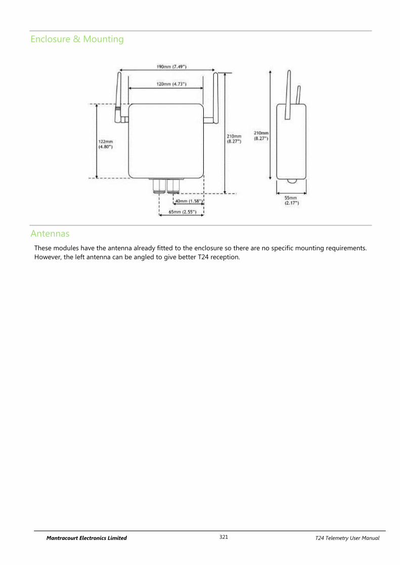
Mantracourt Electronics Limited T24 Telemetry User Manual 321
Enclosure & Mounting
Antennas
These modules have the antenna already fitted to the enclosure so there are no specific mounting requirements.
However, the left antenna can be angled to give better T24 reception.
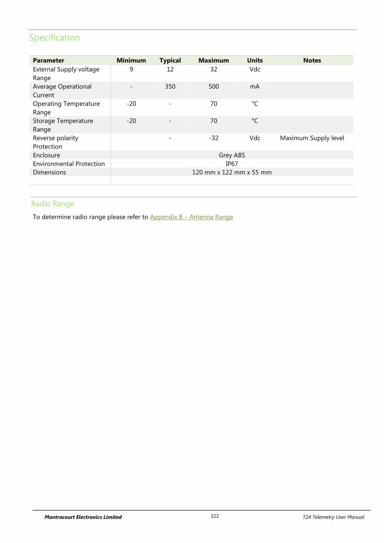
Mantracourt Electronics Limited T24 Telemetry User Manual 322
Specification
Parameter Minimum Typical Maximum Units Notes
External Supply voltage
Range
9 12 32 Vdc
Average Operational
Current
- 350 500 mA
Operating Temperature
Range
-20 - 70 °C
Storage Temperature
Range
-20 - 70 °C
Reverse polarity
Protection
- -32 Vdc Maximum Supply level
Enclosure Grey ABS
Environmental Protection IP67
Dimensions 120 mm x 122 mm x 55 mm
Radio Range
To determine radio range please refer to Appendix B – Antenna Range
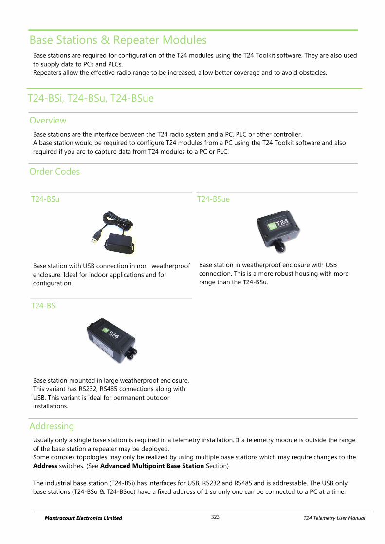
Mantracourt Electronics Limited T24 Telemetry User Manual 323
Base Stations & Repeater Modules
Base stations are required for configuration of the T24 modules using the T24 Toolkit software. They are also used
to supply data to PCs and PLCs.
Repeaters allow the effective radio range to be increased, allow better coverage and to avoid obstacles.
T24-BSi, T24-BSu, T24-BSue
Overview
Base stations are the interface between the T24 radio system and a PC, PLC or other controller.
A base station would be required to configure T24 modules from a PC using the T24 Toolkit software and also
required if you are to capture data from T24 modules to a PC or PLC.
Order Codes
T24-BSu
Base station with USB connection in non weatherproof
enclosure. Ideal for indoor applications and for
configuration.
T24-BSue
Base station in weatherproof enclosure with USB
connection. This is a more robust housing with more
range than the T24-BSu.
T24-BSi
Base station mounted in large weatherproof enclosure.
This variant has RS232, RS485 connections along with
USB. This variant is ideal for permanent outdoor
installations.
Addressing
Usually only a single base station is required in a telemetry installation. If a telemetry module is outside the range
of the base station a repeater may be deployed.
Some complex topologies may only be realized by using multiple base stations which may require changes to the
Address switches. (See Advanced Multipoint Base Station Section)
The industrial base station (T24-BSi) has interfaces for USB, RS232 and RS485 and is addressable. The USB only
base stations (T24-BSu & T24-BSue) have a fixed address of 1 so only one can be connected to a PC at a time.
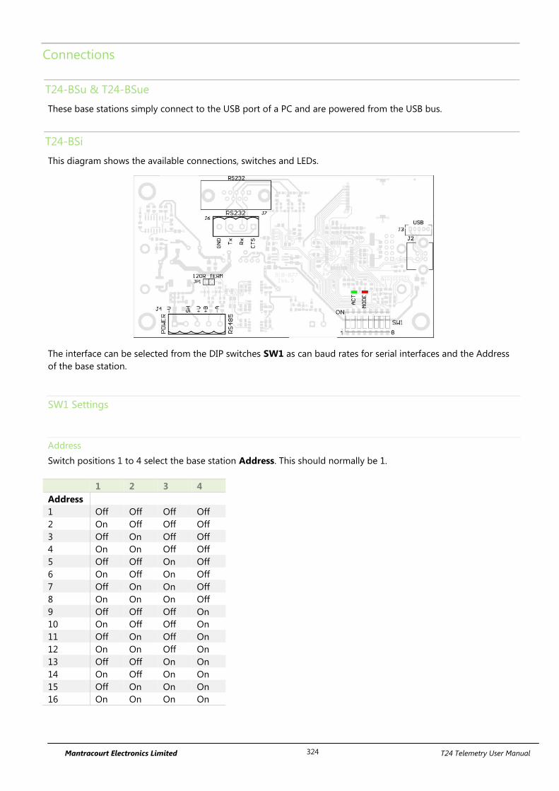
Mantracourt Electronics Limited T24 Telemetry User Manual 324
Connections
T24-BSu & T24-BSue
These base stations simply connect to the USB port of a PC and are powered from the USB bus.
T24-BSi
This diagram shows the available connections, switches and LEDs.
1 8
ON
The interface can be selected from the DIP switches SW1 as can baud rates for serial interfaces and the Address
of the base station.
SW1 Settings
Address
Switch positions 1 to 4 select the base station Address. This should normally be 1.
1 2 3 4
Address
1 Off Off Off Off
2 On Off Off Off
3 Off On Off Off
4 On On Off Off
5 Off Off On Off
6 On Off On Off
7 Off On On Off
8 On On On Off
9 Off Off Off On
10 On Off Off On
11 Off On Off On
12 On On Off On
13 Off Off On On
14 On Off On On
15 Off On On On
16 On On On On
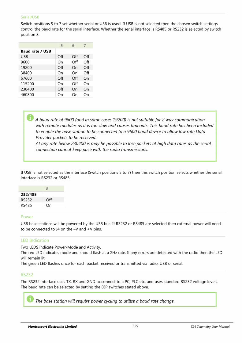
Mantracourt Electronics Limited T24 Telemetry User Manual 325
Serial/USB
Switch positions 5 to 7 set whether serial or USB is used. If USB is not selected then the chosen switch settings
control the baud rate for the serial interface. Whether the serial interface is RS485 or RS232 is selected by switch
position 8.
5 6 7
Baud rate / USB
USB Off Off Off
9600 On Off Off
19200 Off On Off
38400 On On Off
57600 Off Off On
115200 On Off On
230400 Off On On
460800 On On On
A baud rate of 9600 (and in some cases 19200) is not suitable for 2 way communication
with remote modules as it is too slow and causes timeouts. This baud rate has been included
to enable the base station to be connected to a 9600 baud device to allow low rate Data
Provider packets to be received.
At any rate below 230400 is may be possible to lose packets at high data rates as the serial
connection cannot keep pace with the radio transmissions.
If USB is not selected as the interface (Switch positions 5 to 7) then this switch position selects whether the serial
interface is RS232 or RS485.
8
232/485
RS232 Off
RS485 On
Power
USB base stations will be powered by the USB bus. If RS232 or RS485 are selected then external power will need
to be connected to J4 on the –V and +V pins.
LED Indication
Two LEDS indicate Power/Mode and Activity.
The red LED indicates mode and should flash at a 2Hz rate. If any errors are detected with the radio then the LED
will remain lit.
The green LED flashes once for each packet received or transmitted via radio, USB or serial.
RS232
The RS232 interface uses TX, RX and GND to connect to a PC, PLC etc. and uses standard RS232 voltage levels.
The baud rate can be selected by setting the DIP switches stated above.
The base station will require power cycling to utilise a baud rate change.

Mantracourt Electronics Limited T24 Telemetry User Manual 326
Example connection to a PC 9 way D serial connector.
PC 9 Way D Plug Pin Signal Direction Base Station Connection
3 (TX) -> RX J6 RX or J7 Pin 3
2 (RX) <- TX J6 TX or J7 Pin 2
5 (Gnd) GND J6 GND or J7 Pin 5
8 (CTS) <- CTS J6 CTS or J7 Pin 8
RS485
The RS485 interface (This is a 2 wire 485 interface and will not work with 4 wire 485 buses) uses TX, RX and GND
to connect to a PC, PLC etc. and uses standard RS485 voltage levels.
The baud rate can be selected by setting the DIP switches stated above.
The base station will require power cycling to utilise a baud rate change.
Example connection
Depending on the RS485 interface or hardware the connections vary and are not standard therefore we can only
show the connections to the base station. You must refer to the user manual regarding your RS485 connection to
ascertain the correct connections.
PC / PLC Connection Signal Direction Base Station Connection
Refer to RS485 Device User Manual A J4 -A
Refer to RS485 Device User Manual B J4 +B
Refer to RS485 Device User Manual GND J4 SH
Serial Limitations
When using RS232 or RS485 you should use the fastest baud rate possible. At lower rates data can be lost
because it can arrive from the radio faster than the base station can send it serially.
At 9600 baud you will experience communications problems when configuring modules. This baud rate is
too slow for anything other than monitoring data provider packets from modules and even then these
should be at a low rate (around 20 per second ). The slow baud rates are provided to get low rate data
into older systems.
RS485 is a bus master system and is not ideally suited to full communications with modules when
multiple modules are providing data. This is fine for the normal operation of data transmitter but it is
recommended that only the module to be configured is active during configuration.
USB
Connection to the base station will be either a captive USB cable (T24-BSu & T24-BSue) or a USB socket B for
connection using a standard USB A-B cable (T24-BSi J2). There is an optional cable assembly for the T24-BSi to
provide for a USB connection while the module is still fitted to the ABS case (T24-BSi J3).
To communicate with the base station the connected module must use the USB HID Device Class and support
USB 2.0 full speed interface (12Mbits).
The USB connection will also power the base station.

Mantracourt Electronics Limited T24 Telemetry User Manual 327
Communications
In a lot of installations the base station is used to configure and calibrate the T24 modules by use of the T24
Toolkit software.
In this case the user needs only connect the base station to the PC by means of a suitable interface as described
above. The Toolkit software can then be configured to use the desired interface to the base station.
If you intend to write your own software to connect to a T24 module please refer to the T24 Technical Manual for
descriptions of communications protocols.
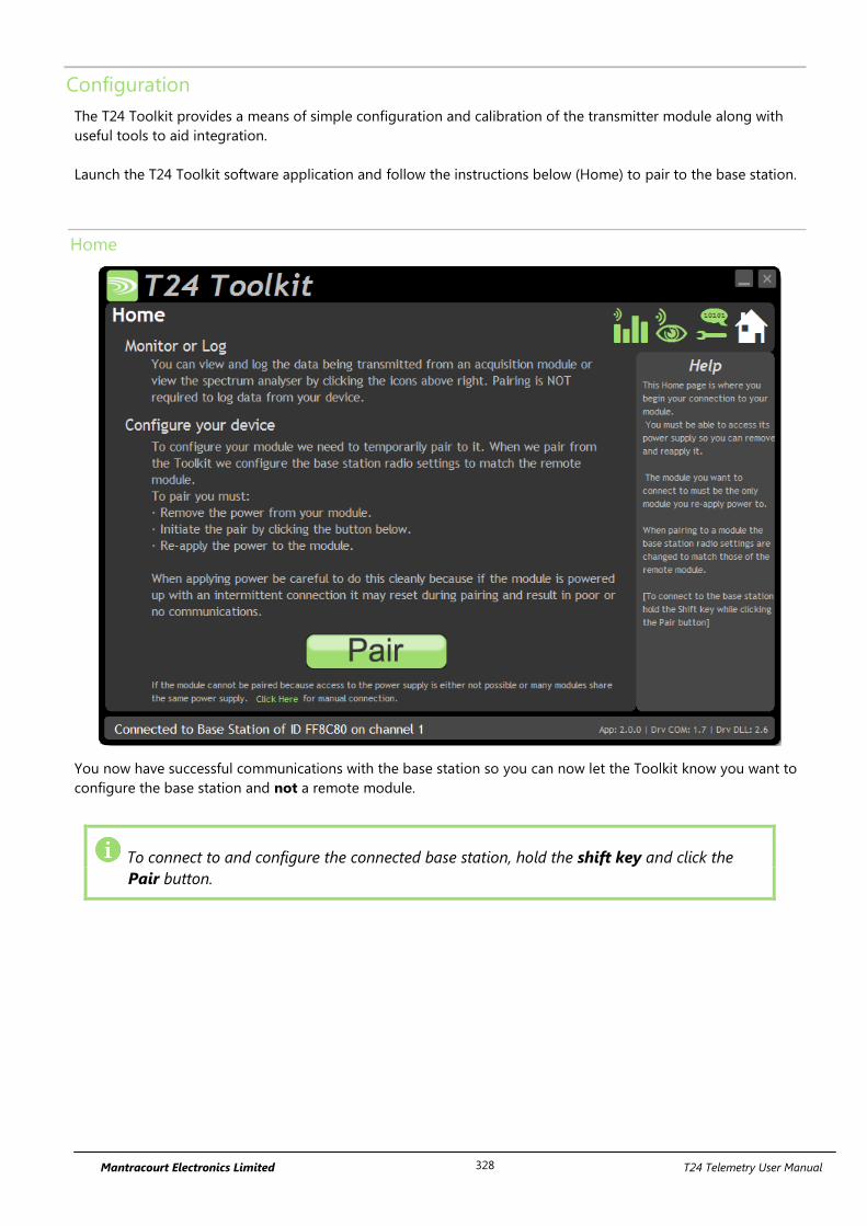
Mantracourt Electronics Limited T24 Telemetry User Manual 328
Configuration
The T24 Toolkit provides a means of simple configuration and calibration of the transmitter module along with
useful tools to aid integration.
Launch the T24 Toolkit software application and follow the instructions below (Home) to pair to the base station.
Home
You now have successful communications with the base station so you can now let the Toolkit know you want to
configure the base station and not a remote module.
To connect to and configure the connected base station, hold the shift key and click the
Pair button.
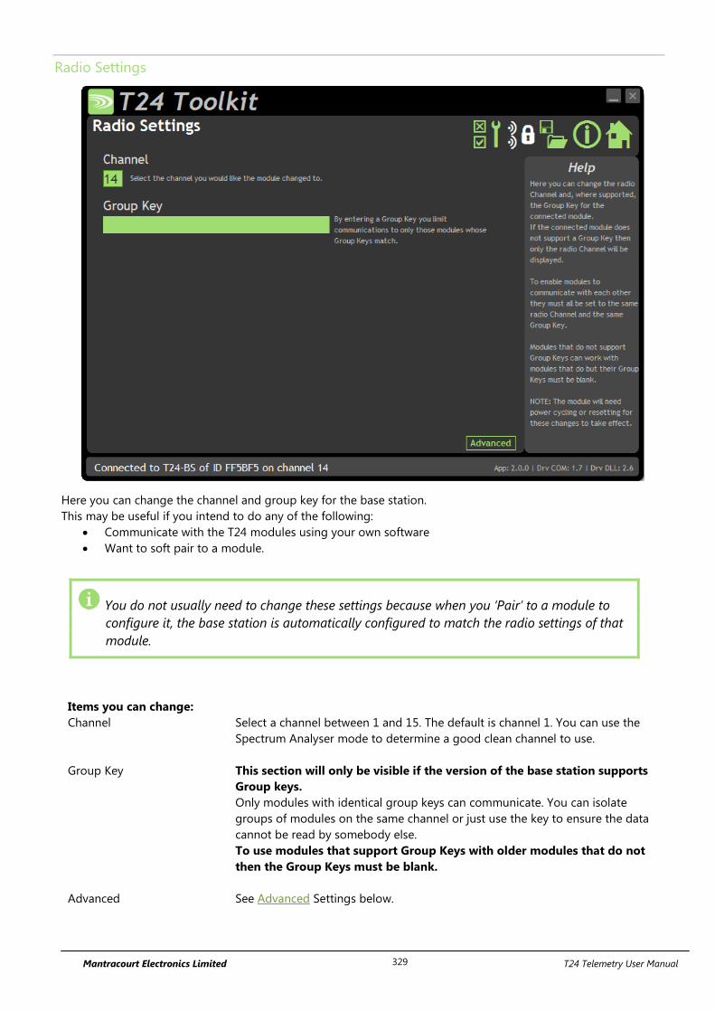
Mantracourt Electronics Limited T24 Telemetry User Manual 329
Radio Settings
Here you can change the channel and group key for the base station.
This may be useful if you intend to do any of the following:
Communicate with the T24 modules using your own software
Want to soft pair to a module.
You do not usually need to change these settings because when you ‘Pair’ to a module to
configure it, the base station is automatically configured to match the radio settings of that
module.
Items you can change:
Channel Select a channel between 1 and 15. The default is channel 1. You can use the
Spectrum Analyser mode to determine a good clean channel to use.
Group Key This section will only be visible if the version of the base station supports
Group keys.
Only modules with identical group keys can communicate. You can isolate
groups of modules on the same channel or just use the key to ensure the data
cannot be read by somebody else.
To use modules that support Group Keys with older modules that do not
then the Group Keys must be blank.
Advanced See Advanced Settings below.
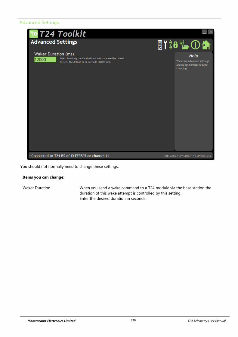
Mantracourt Electronics Limited T24 Telemetry User Manual 330
Advanced Settings
You should not normally need to change these settings.
Items you can change:
Waker Duration When you send a wake command to a T24 module via the base station the
duration of this wake attempt is controlled by this setting.
Enter the desired duration in seconds.
Mantracourt Electronics Limited T24 Telemetry User Manual 331
Enclosure & Mounting
This module is available in a number of different enclosure types. Locate your module and follow the link to view
dimensional and mounting information for that particular enclosure.
T24-BSi
This module is fitted inside our large enclosure. Please see Appendix A – Enclosures & Mounting – ACM for more
information.
T24-BSue
This module is fitted inside our medium enclosure. Please see Appendix A – Enclosures & Mounting – ACMi for
more information.
T24-BSu
This module is fitted inside our small enclosure. Please see Appendix A – Enclosures & Mounting – ACMm for
more information.
Antennas
T24-BSi, T24-BSu, T24-BSue
These modules have the antenna already fitted inside the enclosure so there are no specific mounting
requirements.
Radio Range
To determine radio range please refer to Appendix B – Antenna Range
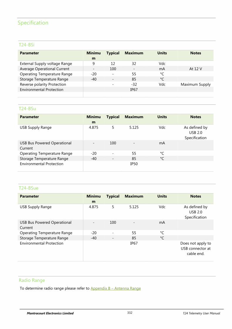
Mantracourt Electronics Limited T24 Telemetry User Manual 332
Specification
T24-BSi
Parameter Minimu
m
Typical Maximum Units Notes
External Supply voltage Range 9 12 32 Vdc
Average Operational Current - 100 - mA At 12 V
Operating Temperature Range -20 - 55 °C
Storage Temperature Range -40 - 85 °C
Reverse polarity Protection - -32 Vdc Maximum Supply
Environmental Protection IP67
T24-BSu
Parameter Minimu
m
Typical Maximum Units Notes
USB Supply Range 4.875 5 5.125 Vdc As defined by
USB 2.0
Specification
USB Bus Powered Operational
Current
- 100 - mA
Operating Temperature Range -20 - 55 °C
Storage Temperature Range -40 - 85 °C
Environmental Protection IP50
T24-BSue
Parameter Minimu
m
Typical Maximum Units Notes
USB Supply Range 4.875 5 5.125 Vdc As defined by
USB 2.0
Specification
USB Bus Powered Operational
Current
- 100 - mA
Operating Temperature Range -20 - 55 °C
Storage Temperature Range -40 - 85 °C
Environmental Protection IP67 Does not apply to
USB connector at
cable end.
Radio Range
To determine radio range please refer to Appendix B – Antenna Range
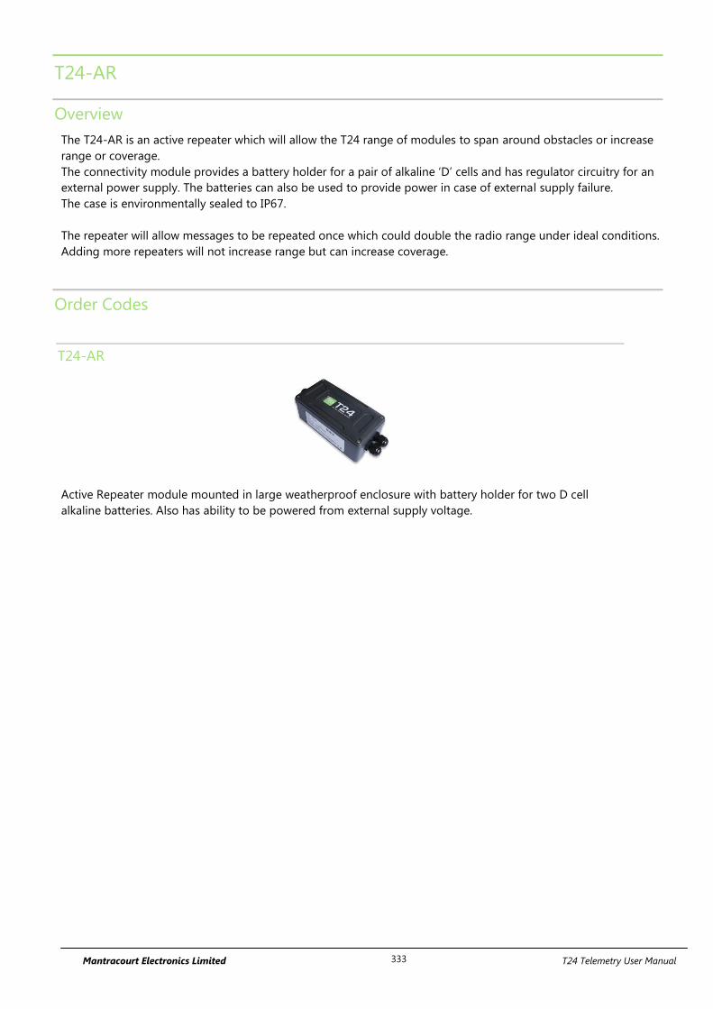
Mantracourt Electronics Limited T24 Telemetry User Manual 333
T24-AR
Overview
The T24-AR is an active repeater which will allow the T24 range of modules to span around obstacles or increase
range or coverage.
The connectivity module provides a battery holder for a pair of alkaline ‘D’ cells and has regulator circuitry for an
external power supply. The batteries can also be used to provide power in case of external supply failure.
The case is environmentally sealed to IP67.
The repeater will allow messages to be repeated once which could double the radio range under ideal conditions.
Adding more repeaters will not increase range but can increase coverage.
Order Codes
T24-AR
Active Repeater module mounted in large weatherproof enclosure with battery holder for two D cell
alkaline batteries. Also has ability to be powered from external supply voltage.
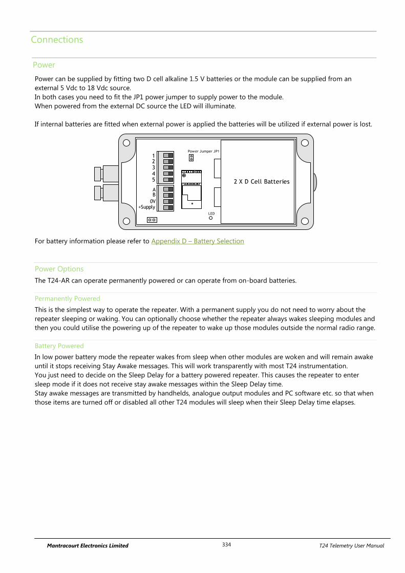
Mantracourt Electronics Limited T24 Telemetry User Manual 334
Connections
Power
Power can be supplied by fitting two D cell alkaline 1.5 V batteries or the module can be supplied from an
external 5 Vdc to 18 Vdc source.
In both cases you need to fit the JP1 power jumper to supply power to the module.
When powered from the external DC source the LED will illuminate.
If internal batteries are fitted when external power is applied the batteries will be utilized if external power is lost.
2 X D Cell Batteries
AB
0V+Supply
12345
Power Jumper JP1
LED
For battery information please refer to Appendix D – Battery Selection
Power Options
The T24-AR can operate permanently powered or can operate from on-board batteries.
Permanently Powered
This is the simplest way to operate the repeater. With a permanent supply you do not need to worry about the
repeater sleeping or waking. You can optionally choose whether the repeater always wakes sleeping modules and
then you could utilise the powering up of the repeater to wake up those modules outside the normal radio range.
Battery Powered
In low power battery mode the repeater wakes from sleep when other modules are woken and will remain awake
until it stops receiving Stay Awake messages. This will work transparently with most T24 instrumentation.
You just need to decide on the Sleep Delay for a battery powered repeater. This causes the repeater to enter
sleep mode if it does not receive stay awake messages within the Sleep Delay time.
Stay awake messages are transmitted by handhelds, analogue output modules and PC software etc. so that when
those items are turned off or disabled all other T24 modules will sleep when their Sleep Delay time elapses.
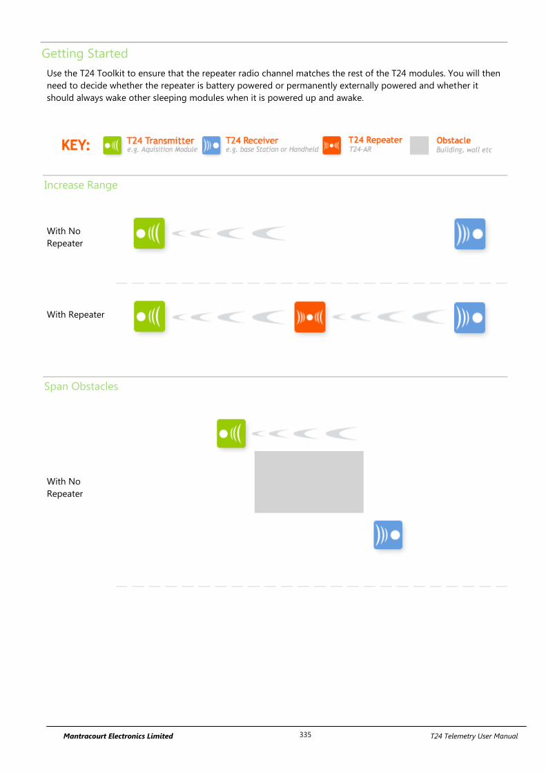
Mantracourt Electronics Limited T24 Telemetry User Manual 335
Getting Started
Use the T24 Toolkit to ensure that the repeater radio channel matches the rest of the T24 modules. You will then
need to decide whether the repeater is battery powered or permanently externally powered and whether it
should always wake other sleeping modules when it is powered up and awake.
Increase Range
With No
Repeater
With Repeater
Span Obstacles
With No
Repeater
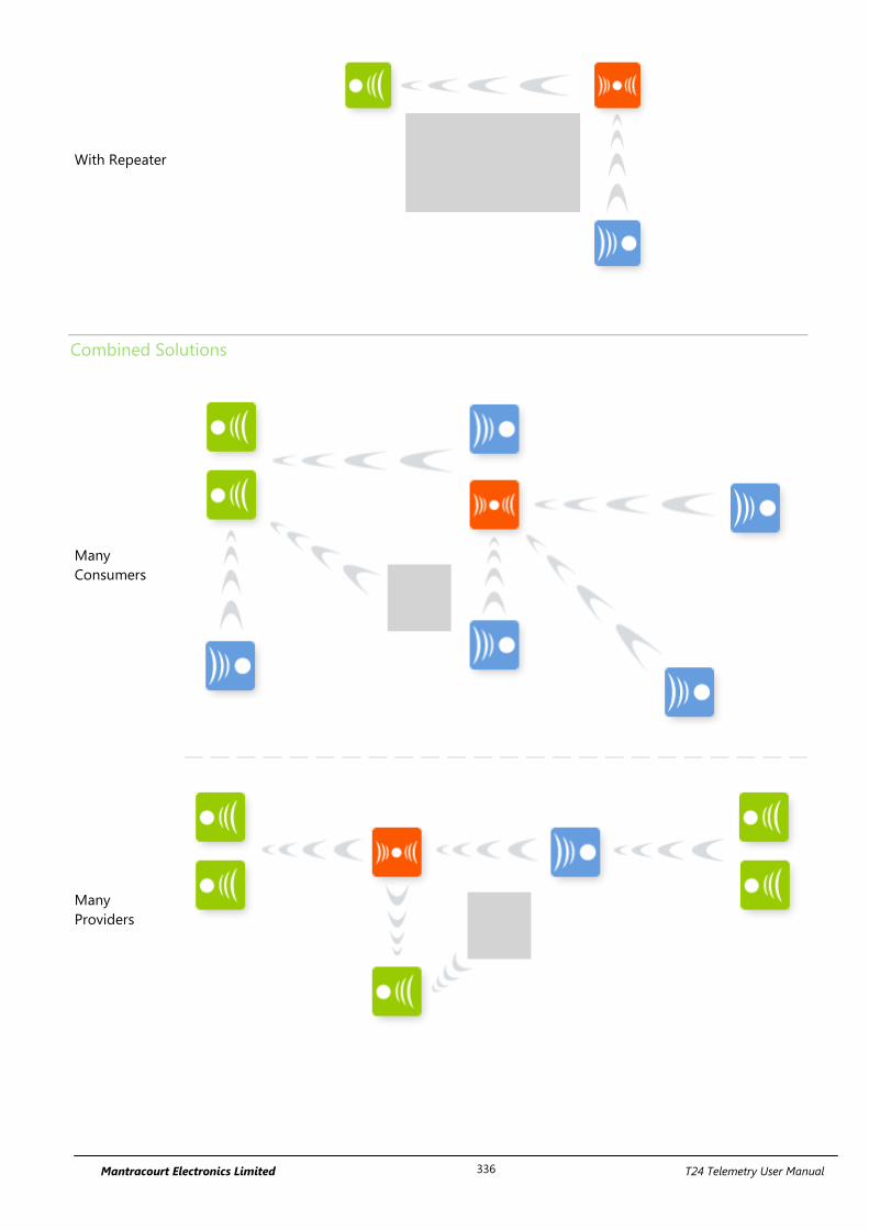
Mantracourt Electronics Limited T24 Telemetry User Manual 336
With Repeater
Combined Solutions
Many
Consumers
Many
Providers
Mantracourt Electronics Limited T24 Telemetry User Manual 337
Considerations
Each repeater can effectively double the amount of traffic transmitted. Be careful not to introduce too
many repeaters that are within range of each other as there may be un-necessary duplication of radio
traffic. Carefully plan the layout of radio modules to minimise this.
Using the Data Provider monitor in the T24 Toolkit can show the amount of traffic. The T24 Toolkit on a
laptop or netbook is ideal for checking installations as it is mobile so traffic can be monitored at different
points in the installation.
A repeater will not repeat a packet that has already been repeated. Hence there is only one extra ‘hop’
introduced and a maximum range increase to 2X.
When waking remote modules separated by a repeater and that repeater is asleep it may take twice as
long to wake a module as when no repeater is involved.
If the repeater is to be battery powered use the same Sleep Delay as is suitable for the transmitter
modules in the system.
You cannot pair to a module through a repeater although it may be possible to configure module
through a repeater by soft pairing. The results will vary depending on the number of repeaters and
amount of radio traffic. In some cases it may be necessary to power down repeaters when configuring
modules.
Most data consumer modules and software issue a broadcast wake when turned on or activated and this
will also wake a sleeping repeater which will then proceed to wake those modules within its range.
But some modules only wake specific single target modules such as the T24-HS handheld module and
the T24-AO1 analogue output module. For these modules to wake the repeater they must be fitted with
at least version 2.1 radio modules. This only affects repeaters with a SleepDelay set.
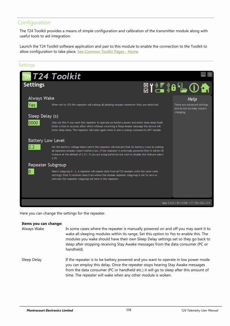
Mantracourt Electronics Limited T24 Telemetry User Manual 338
Configuration
The T24 Toolkit provides a means of simple configuration and calibration of the transmitter module along with
useful tools to aid integration.
Launch the T24 Toolkit software application and pair to this module to enable the connection to the Toolkit to
allow configuration to take place. See Common Toolkit Pages - Home
Settings
Here you can change the settings for the repeater.
Items you can change:
Always Wake In some cases where the repeater is manually powered on and off you may want it to
wake all sleeping modules within its range. Set this option to Yes to enable this. The
modules you wake should have their own Sleep Delay settings set so they go back to
sleep after stopping receiving Stay Awake messages from the data consumer (PC or
handheld).
Sleep Delay If the repeater is to be battery powered and you want to operate in low power mode
you can employ this delay. Once the repeater stops hearing Stay Awake messages
from the data consumer (PC or handheld etc.) it will go to sleep after this amount of
time. The repeater will wake when any other module is woken.
Mantracourt Electronics Limited T24 Telemetry User Manual 339
Battery Low Level Select the battery voltage below which the repeater will report a low battery.
It does this by making all repeated modules report a low battery so the data consumer
(a handheld or PC software etc.) will be able to detect a problem.
The battery level applies to the voltage seen after 3 V regulation. The default is
2.2 V and can be left at this when the repeater is powered externally.
If the repeater is battery powered and you wish to disable this feature select 2.0 V
Enclosure & Mounting
This module is fitted inside our ACM ABS enclosure. Please see Appendix A – Enclosures & Mounting – ACM for
more information.
Antennas
These modules have the antenna already fitted inside the enclosure so there are no specific mounting
requirements.
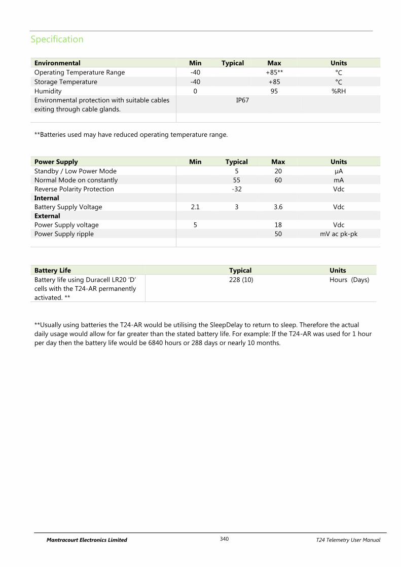
Mantracourt Electronics Limited T24 Telemetry User Manual 340
Specification
Environmental Min Typical Max Units
Operating Temperature Range -40 +85** °C
Storage Temperature -40 +85 °C
Humidity 0 95 %RH
Environmental protection with suitable cables
exiting through cable glands.
IP67
**Batteries used may have reduced operating temperature range.
Power Supply Min Typical Max Units
Standby / Low Power Mode 5 20 µA
Normal Mode on constantly 55 60 mA
Reverse Polarity Protection -32 Vdc
Internal
Battery Supply Voltage 2.1 3 3.6 Vdc
External
Power Supply voltage 5 18 Vdc
Power Supply ripple 50 mV ac pk-pk
Battery Life Typical Units
Battery life using Duracell LR20 ‘D’
cells with the T24-AR permanently
activated. **
228 (10)
Hours (Days)
**Usually using batteries the T24-AR would be utilising the SleepDelay to return to sleep. Therefore the actual
daily usage would allow for far greater than the stated battery life. For example: If the T24-AR was used for 1 hour
per day then the battery life would be 6840 hours or 288 days or nearly 10 months.
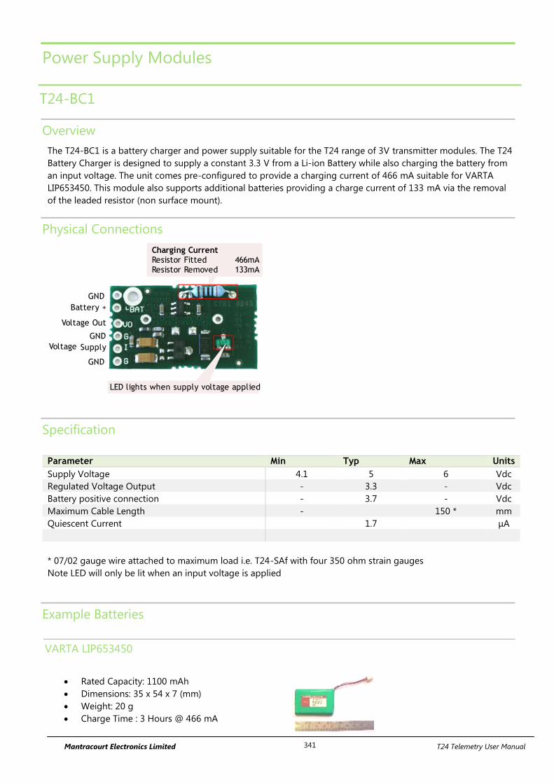
Mantracourt Electronics Limited T24 Telemetry User Manual 341
Power Supply Modules
T24-BC1
Overview
The T24-BC1 is a battery charger and power supply suitable for the T24 range of 3V transmitter modules. The T24
Battery Charger is designed to supply a constant 3.3 V from a Li-ion Battery while also charging the battery from
an input voltage. The unit comes pre-configured to provide a charging current of 466 mA suitable for VARTA
LIP653450. This module also supports additional batteries providing a charge current of 133 mA via the removal
of the leaded resistor (non surface mount).
Physical Connections
GND
Charging CurrentResistor Fitted 466mAResistor Removed 133mA
LED lights when supply voltage applied
GND
GND
Battery +
Voltage Out
Supply Voltage
Specification
Parameter Min Typ Max Units
Supply Voltage 4.1 5 6 Vdc
Regulated Voltage Output - 3.3 - Vdc
Battery positive connection - 3.7 - Vdc
Maximum Cable Length - 150 * mm
Quiescent Current 1.7 μA
* 07/02 gauge wire attached to maximum load i.e. T24-SAf with four 350 ohm strain gauges
Note LED will only be lit when an input voltage is applied
Example Batteries
VARTA LIP653450
Rated Capacity: 1100 mAh
Dimensions: 35 x 54 x 7 (mm)
Weight: 20 g
Charge Time : 3 Hours @ 466 mA
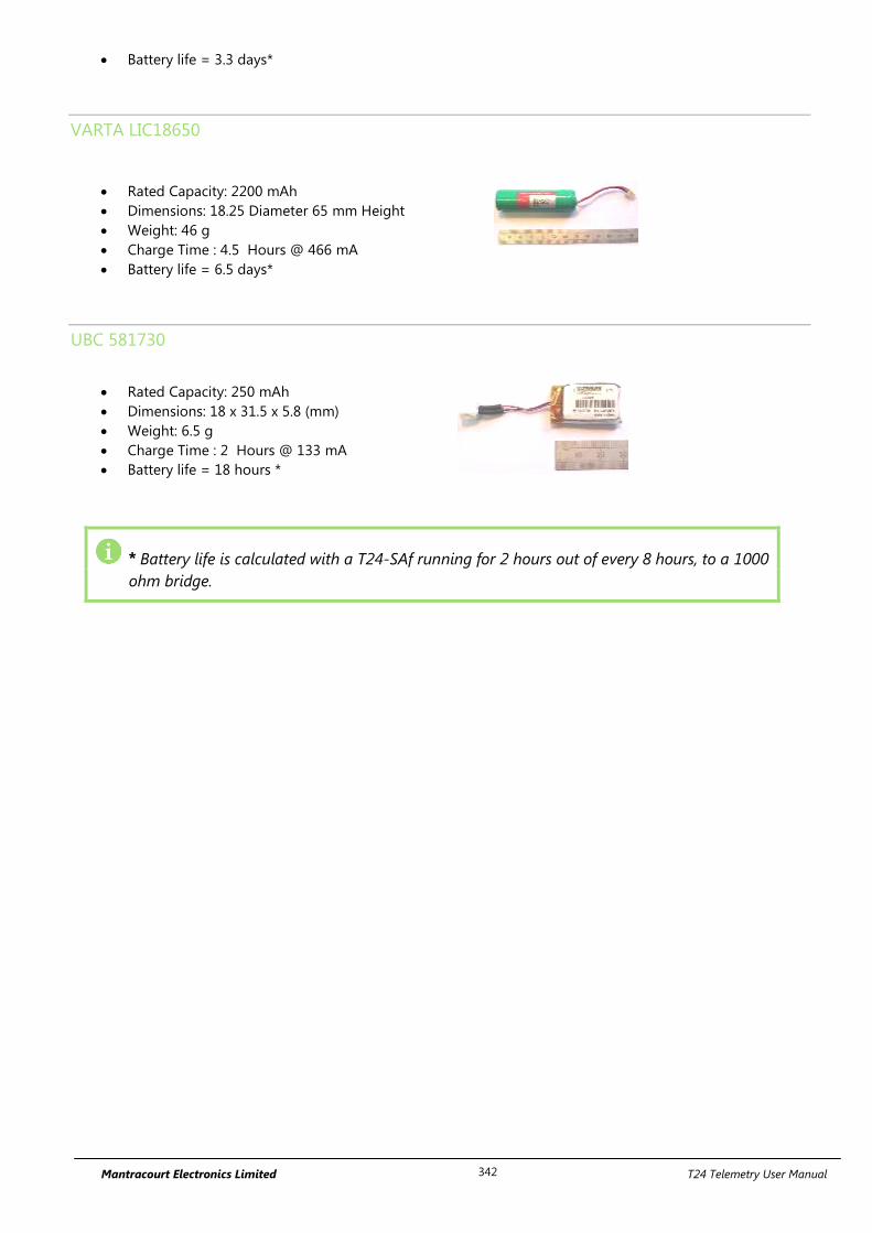
Mantracourt Electronics Limited T24 Telemetry User Manual 342
Battery life = 3.3 days*
VARTA LIC18650
Rated Capacity: 2200 mAh
Dimensions: 18.25 Diameter 65 mm Height
Weight: 46 g
Charge Time : 4.5 Hours @ 466 mA
Battery life = 6.5 days*
UBC 581730
Rated Capacity: 250 mAh
Dimensions: 18 x 31.5 x 5.8 (mm)
Weight: 6.5 g
Charge Time : 2 Hours @ 133 mA
Battery life = 18 hours *
* Battery life is calculated with a T24-SAf running for 2 hours out of every 8 hours, to a 1000
ohm bridge.
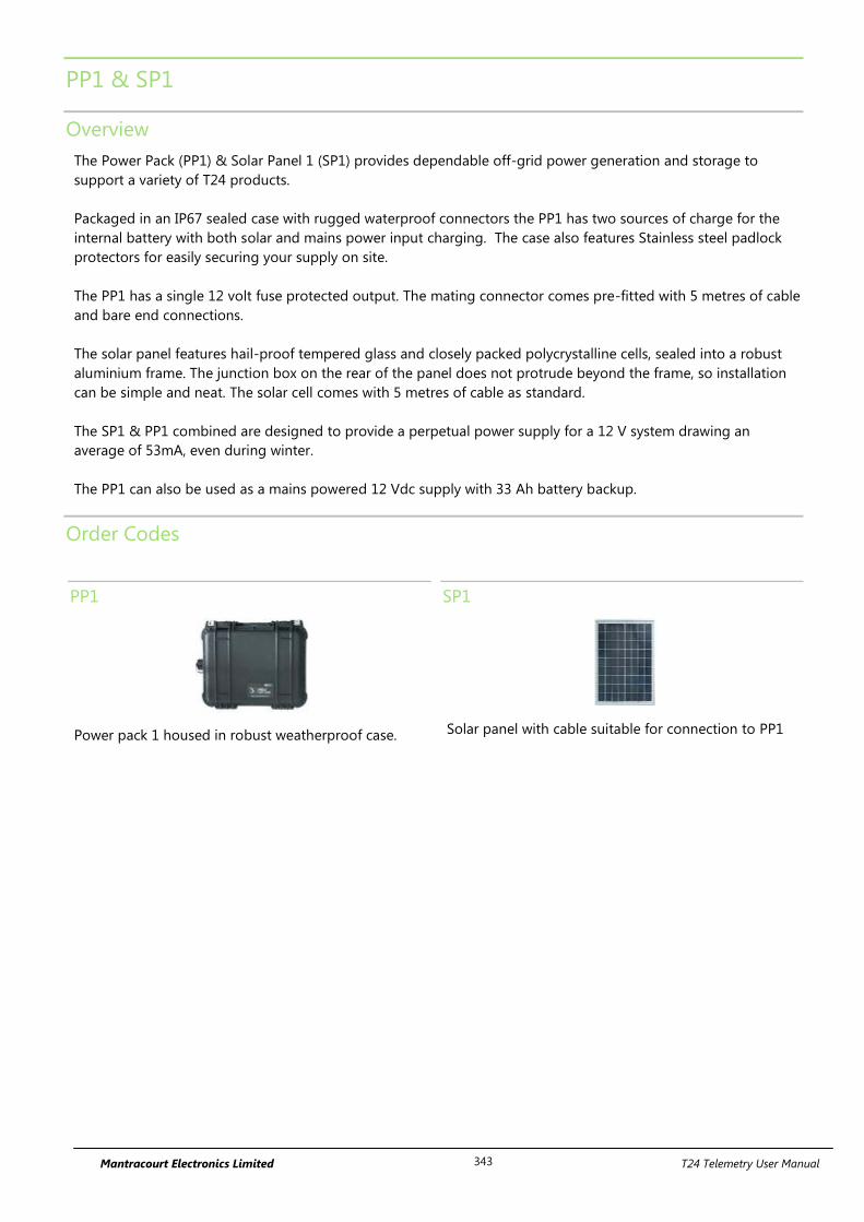
Mantracourt Electronics Limited T24 Telemetry User Manual 343
PP1 & SP1
Overview
The Power Pack (PP1) & Solar Panel 1 (SP1) provides dependable off-grid power generation and storage to
support a variety of T24 products.
Packaged in an IP67 sealed case with rugged waterproof connectors the PP1 has two sources of charge for the
internal battery with both solar and mains power input charging. The case also features Stainless steel padlock
protectors for easily securing your supply on site.
The PP1 has a single 12 volt fuse protected output. The mating connector comes pre-fitted with 5 metres of cable
and bare end connections.
The solar panel features hail-proof tempered glass and closely packed polycrystalline cells, sealed into a robust
aluminium frame. The junction box on the rear of the panel does not protrude beyond the frame, so installation
can be simple and neat. The solar cell comes with 5 metres of cable as standard.
The SP1 & PP1 combined are designed to provide a perpetual power supply for a 12 V system drawing an
average of 53mA, even during winter.
The PP1 can also be used as a mains powered 12 Vdc supply with 33 Ah battery backup.
Order Codes
PP1
Power pack 1 housed in robust weatherproof case.
SP1
Solar panel with cable suitable for connection to PP1
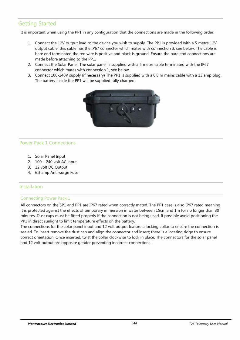
Mantracourt Electronics Limited T24 Telemetry User Manual 344
Getting Started
It is important when using the PP1 in any configuration that the connections are made in the following order:
1. Connect the 12V output lead to the device you wish to supply. The PP1 is provided with a 5 metre 12V
output cable, this cable has the IP67 connector which mates with connection 3, see below. The cable is
bare end terminated the red wire is positive and black is ground. Ensure the bare end connections are
made before attaching to the PP1.
2. Connect the Solar Panel. The solar panel is supplied with a 5 metre cable terminated with the IP67
connector which mates with connection 1, see below.
3. Connect 100-240V supply (if necessary) The PP1 is supplied with a 0.8 m mains cable with a 13 amp plug.
The battery inside the PP1 will be supplied fully charged.
Power Pack 1 Connections
1. Solar Panel Input
2. 100 – 240 volt AC input
3. 12 volt DC Output
4. 6.3 amp Anti-surge Fuse
Installation
Connecting Power Pack 1
All connectors on the SP1 and PP1 are IP67 rated when correctly mated. The PP1 case is also IP67 rated meaning
it is protected against the effects of temporary immersion in water between 15cm and 1m for no longer than 30
minutes. Dust caps must be fitted properly if the connection is not being used. If possible avoid positioning the
PP1 in direct sunlight to limit temperature effects on the battery.
The connections for the solar panel input and 12 volt output feature a locking collar to ensure the connection is
sealed. To insert remove the dust cap and align the connector and insert; there is a locating ridge to ensure
correct orientation. Once inserted, twist the collar clockwise to lock in place. The connectors for the solar panel
and 12 volt output are opposite gender preventing incorrect connections.
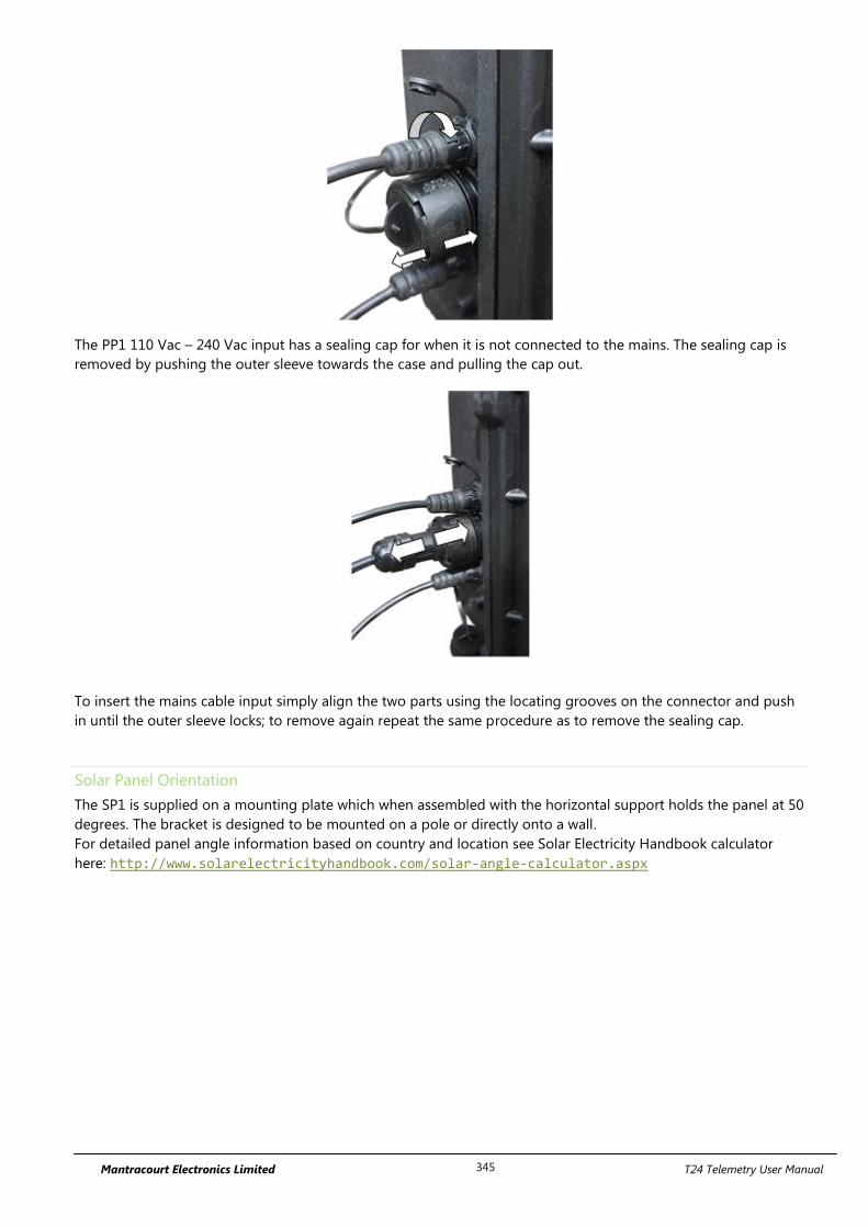
Mantracourt Electronics Limited T24 Telemetry User Manual 345
The PP1 110 Vac – 240 Vac input has a sealing cap for when it is not connected to the mains. The sealing cap is
removed by pushing the outer sleeve towards the case and pulling the cap out.
To insert the mains cable input simply align the two parts using the locating grooves on the connector and push
in until the outer sleeve locks; to remove again repeat the same procedure as to remove the sealing cap.
Solar Panel Orientation
The SP1 is supplied on a mounting plate which when assembled with the horizontal support holds the panel at 50
degrees. The bracket is designed to be mounted on a pole or directly onto a wall.
For detailed panel angle information based on country and location see Solar Electricity Handbook calculator
here: http://www.solarelectricityhandbook.com/solar-angle-calculator.aspx
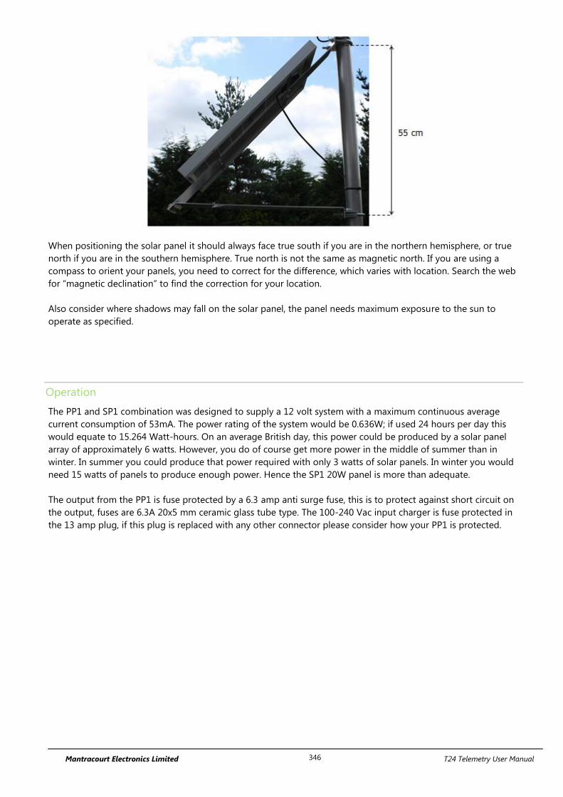
Mantracourt Electronics Limited T24 Telemetry User Manual 346
When positioning the solar panel it should always face true south if you are in the northern hemisphere, or true
north if you are in the southern hemisphere. True north is not the same as magnetic north. If you are using a
compass to orient your panels, you need to correct for the difference, which varies with location. Search the web
for “magnetic declination” to find the correction for your location.
Also consider where shadows may fall on the solar panel, the panel needs maximum exposure to the sun to
operate as specified.
Operation
The PP1 and SP1 combination was designed to supply a 12 volt system with a maximum continuous average
current consumption of 53mA. The power rating of the system would be 0.636W; if used 24 hours per day this
would equate to 15.264 Watt-hours. On an average British day, this power could be produced by a solar panel
array of approximately 6 watts. However, you do of course get more power in the middle of summer than in
winter. In summer you could produce that power required with only 3 watts of solar panels. In winter you would
need 15 watts of panels to produce enough power. Hence the SP1 20W panel is more than adequate.
The output from the PP1 is fuse protected by a 6.3 amp anti surge fuse, this is to protect against short circuit on
the output, fuses are 6.3A 20x5 mm ceramic glass tube type. The 100-240 Vac input charger is fuse protected in
the 13 amp plug, if this plug is replaced with any other connector please consider how your PP1 is protected.
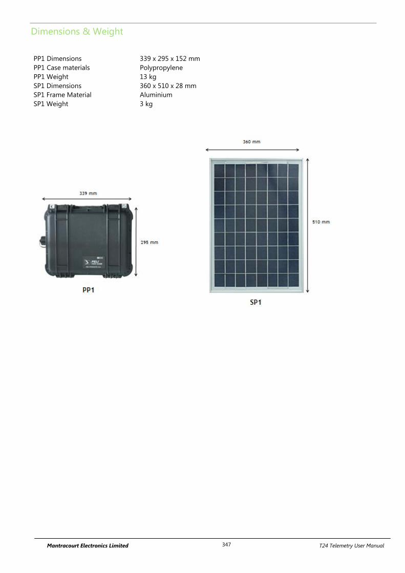
Mantracourt Electronics Limited T24 Telemetry User Manual 347
Dimensions & Weight
PP1 Dimensions
PP1 Case materials
PP1 Weight
SP1 Dimensions
SP1 Frame Material
SP1 Weight
339 x 295 x 152 mm
Polypropylene
13 kg
360 x 510 x 28 mm
Aluminium
3 kg
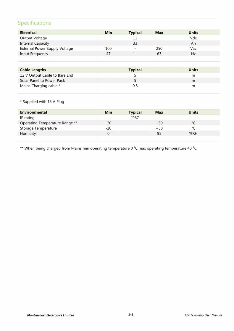
Mantracourt Electronics Limited T24 Telemetry User Manual 348
Specifications
Electrical Min Typical Max Units
Output Voltage 12 Vdc
Internal Capacity 33 Ah
External Power Supply Voltage 100 - 250 Vac
Input Frequency 47 - 63 Hz
Cable Lengths Typical Units
12 V Output Cable to Bare End 5 m
Solar Panel to Power Pack 5 m
Mains Charging cable * 0.8 m
* Supplied with 13 A Plug
Environmental Min Typical Max Units
IP rating IP67
Operating Temperature Range ** -20 +50 °C
Storage Temperature -20 +50 °C
Humidity 0 95 %RH
** When being charged from Mains min operating temperature 0 o
C max operating temperature 40 oC
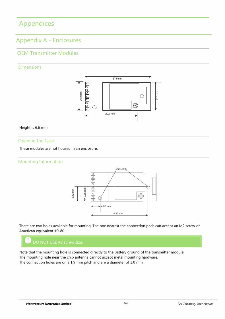
Mantracourt Electronics Limited T24 Telemetry User Manual 349
Appendices
Appendix A - Enclosures
OEM Transmitter Modules
Dimensions
37.5 mm
29.8 mm
16.0
mm
16
.8 m
m
Height is 6.6 mm
Opening the Case
These modules are not housed in an enclosure.
Mounting Information
4.80 mm
32.12 mm
8.4
2 m
m
2.1
5 m
m
O 2.1 mm
There are two holes available for mounting. The one nearest the connection pads can accept an M2 screw or
American equivalent #0-80.
DO NOT USE #2 screw size.
Note that the mounting hole is connected directly to the Battery ground of the transmitter module.
The mounting hole near the chip antenna cannot accept metal mounting hardware.
The connection holes are on a 1.9 mm pitch and are a diameter of 1.0 mm.

Mantracourt Electronics Limited T24 Telemetry User Manual 350
Antenna Position
Modules that use an external antenna can be mounted anywhere but the mounting of the antenna will have
restrictions. See the appropriate section in Appendix B - Antennas
Modules with an internal chip antenna have the antenna at one end of the board with the metal can on.
Environmental Protection
These modules are not protected against the environment.
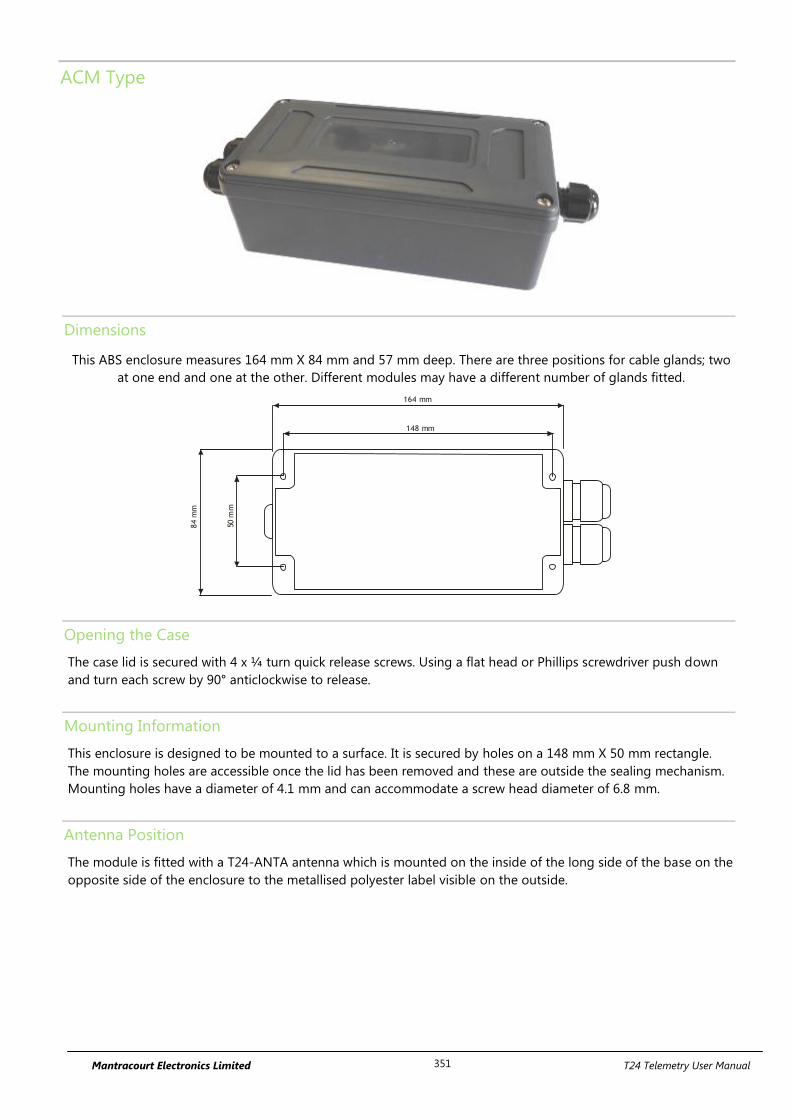
Mantracourt Electronics Limited T24 Telemetry User Manual 351
ACM Type
Dimensions
This ABS enclosure measures 164 mm X 84 mm and 57 mm deep. There are three positions for cable glands; two
at one end and one at the other. Different modules may have a different number of glands fitted.
148 mm
164 mm
84
mm
50 m
m
Opening the Case
The case lid is secured with 4 x ¼ turn quick release screws. Using a flat head or Phillips screwdriver push down
and turn each screw by 90° anticlockwise to release.
Mounting Information
This enclosure is designed to be mounted to a surface. It is secured by holes on a 148 mm X 50 mm rectangle.
The mounting holes are accessible once the lid has been removed and these are outside the sealing mechanism.
Mounting holes have a diameter of 4.1 mm and can accommodate a screw head diameter of 6.8 mm.
Antenna Position
The module is fitted with a T24-ANTA antenna which is mounted on the inside of the long side of the base on the
opposite side of the enclosure to the metallised polyester label visible on the outside.
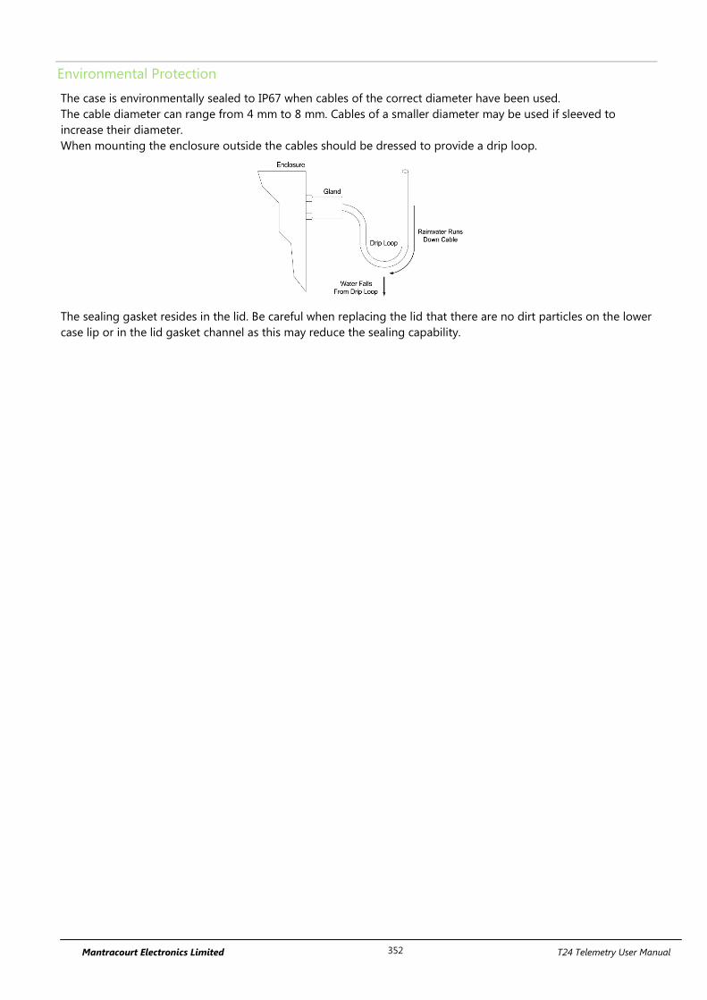
Mantracourt Electronics Limited T24 Telemetry User Manual 352
Environmental Protection
The case is environmentally sealed to IP67 when cables of the correct diameter have been used.
The cable diameter can range from 4 mm to 8 mm. Cables of a smaller diameter may be used if sleeved to
increase their diameter.
When mounting the enclosure outside the cables should be dressed to provide a drip loop.
The sealing gasket resides in the lid. Be careful when replacing the lid that there are no dirt particles on the lower
case lip or in the lid gasket channel as this may reduce the sealing capability.
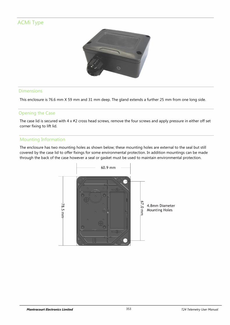
Mantracourt Electronics Limited T24 Telemetry User Manual 353
ACMi Type
Dimensions
This enclosure is 76.6 mm X 59 mm and 31 mm deep. The gland extends a further 25 mm from one long side.
Opening the Case
The case lid is secured with 4 x #2 cross head screws, remove the four screws and apply pressure in either off set
corner fixing to lift lid.
Mounting Information
The enclosure has two mounting holes as shown below; these mounting holes are external to the seal but still
covered by the case lid to offer fixings for some environmental protection. In addition mountings can be made
through the back of the case however a seal or gasket must be used to maintain environmental protection.
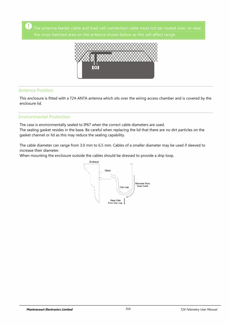
Mantracourt Electronics Limited T24 Telemetry User Manual 354
The antenna feeder cable and load cell connection cable must not be routed over, or near,
the cross hatched area on the antenna shown below as this will affect range.
Antenna Position
This enclosure is fitted with a T24-ANTA antenna which sits over the wiring access chamber and is covered by the
enclosure lid.
Environmental Protection
The case is environmentally sealed to IP67 when the correct cable diameters are used.
The sealing gasket resides in the base. Be careful when replacing the lid that there are no dirt particles on the
gasket channel or lid as this may reduce the sealing capability.
The cable diameter can range from 3.0 mm to 6.5 mm. Cables of a smaller diameter may be used if sleeved to
increase their diameter.
When mounting the enclosure outside the cables should be dressed to provide a drip loop.
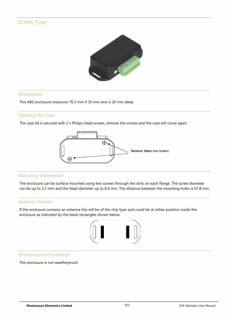
Mantracourt Electronics Limited T24 Telemetry User Manual 355
ACMm Type
Dimensions
This ABS enclosure measures 76.3 mm X 35 mm and is 20 mm deep.
Opening the Case
The case lid is secured with 2 x Philips head screws, remove the screws and the case will come apart.
Mounting Information
The enclosure can be surface mounted using two screws through the slots on each flange. The screw diameter
can be up to 3.3 mm and the head diameter up to 8.0 mm. The distance between the mounting holes is 67.8 mm.
Antenna Position
If the enclosure contains an antenna this will be of the chip type and could be at either position inside the
enclosure as indicated by the black rectangles shown below.
Environmental Protection
This enclosure is not weatherproof.
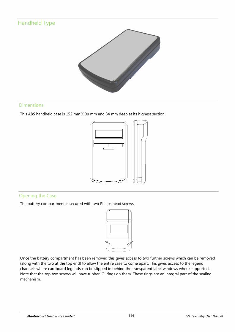
Mantracourt Electronics Limited T24 Telemetry User Manual 356
Handheld Type
Dimensions
This ABS handheld case is 152 mm X 90 mm and 34 mm deep at its highest section.
Opening the Case
The battery compartment is secured with two Philips head screws.
Once the battery compartment has been removed this gives access to two further screws which can be removed
(along with the two at the top end) to allow the entire case to come apart. This gives access to the legend
channels where cardboard legends can be slipped in behind the transparent label windows where supported.
Note that the top two screws will have rubber ‘O’ rings on them. These rings are an integral part of the sealing
mechanism.
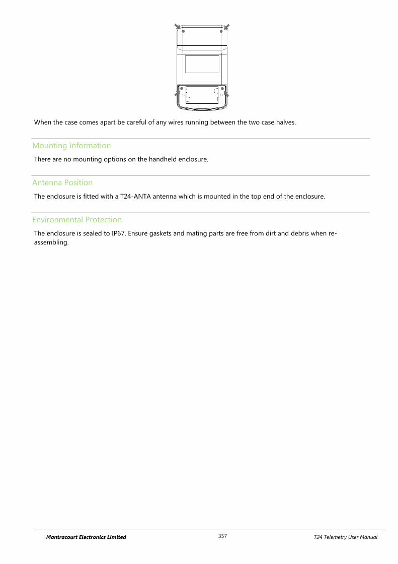
Mantracourt Electronics Limited T24 Telemetry User Manual 357
When the case comes apart be careful of any wires running between the two case halves.
Mounting Information
There are no mounting options on the handheld enclosure.
Antenna Position
The enclosure is fitted with a T24-ANTA antenna which is mounted in the top end of the enclosure.
Environmental Protection
The enclosure is sealed to IP67. Ensure gaskets and mating parts are free from dirt and debris when re-
assembling.
Mantracourt Electronics Limited T24 Telemetry User Manual 358
Appendix B - Antennas
Overview
Radio performance at microwave wavelengths is very dependent upon the operating environment; any structure
within the operating region of the radios will give rise to three effects:
Obscuration. Obscuration will result in reduced range and occurs when an obstruction masks the line-of-sight
between radios.
Aberrations to the horizontal and vertical space patterns. Distortion of these patterns may occur if structures
or objects are placed in the near or intermediate field of the antenna. The effect will be to distort the coverage
patterns, adversely affecting range and link quality.
Reflection. Any object placed in line-of-sight of the transmit antenna will result in signals arriving at the receiver
by an indirect path. Degradation of performance due to reflection (multipath effects) appears as reduced range or
poor link quality.
Any of the above will reduce RSSI figures, an increase in the packet loss rate and in extreme cases complete loss
of signal. Fortunately, if consideration is given to these effects at the integration stage then a good quality link
will be obtained.
Guidelines for product design:
When selecting materials for product enclosures, preference should be given to fibreglass, light coloured ABS or
Polypropylene (Dark colours can sometimes be achieved with the addition of carbon which can attenuate the
radio signal); at the wavelength of 2.4GHz radio other materials will adversely affect the signal by attenuation,
refraction or change in polarisation.
If the application demands that the radio is fitted inside a metal enclosure then ensure that the specified
clearances are maintained around the antenna and design in a fibreglass RF window at least as large as the
clearance dimensions but ideally as large as possible.
RA24i radios fitted inside a product should be oriented so that the chip antenna will be vertical when the product
is in its normal operating position.
Guidelines for installation:
When planning installations ensure that line-of –sight between nodes is maintained and that objects or structures
are kept at least one metre away from antennae wherever possible.
To avoid poor link quality between a RA24i radio and a handheld module ensure that the RA24i is mounted so
that the chip antenna is vertical. Improvement may also be obtained by altering the height above ground of the
RA24i; a small increase or reduction in antenna elevation will often improve reception.
Range underwater is only 100 mm or so depending on packet rate. Best performance underwater is obtained by
using low packet rates and immersing water-proofed antennae rather than water-tight enclosures containing the
antennae.
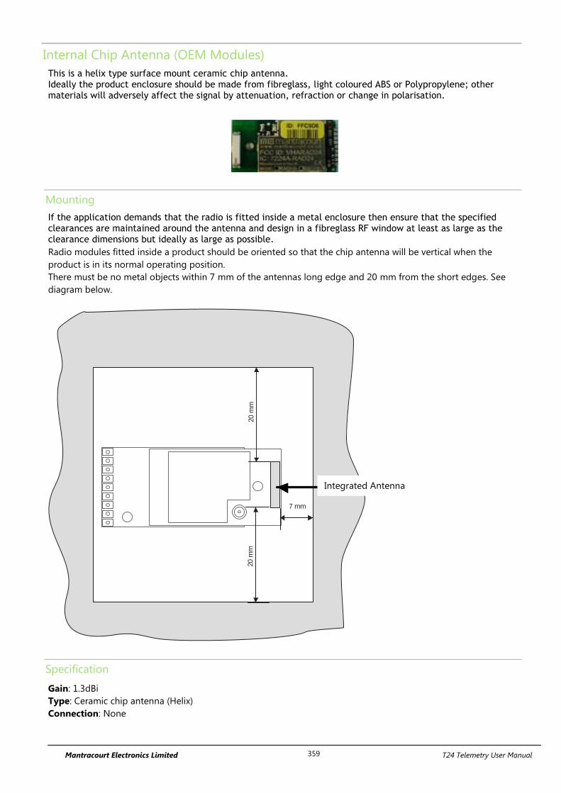
Mantracourt Electronics Limited T24 Telemetry User Manual 359
Internal Chip Antenna (OEM Modules)
This is a helix type surface mount ceramic chip antenna. Ideally the product enclosure should be made from fibreglass, light coloured ABS or Polypropylene; other materials will adversely affect the signal by attenuation, refraction or change in polarisation.
Mounting
If the application demands that the radio is fitted inside a metal enclosure then ensure that the specified clearances are maintained around the antenna and design in a fibreglass RF window at least as large as the clearance dimensions but ideally as large as possible.
Radio modules fitted inside a product should be oriented so that the chip antenna will be vertical when the
product is in its normal operating position.
There must be no metal objects within 7 mm of the antennas long edge and 20 mm from the short edges. See
diagram below.
7 mm
20 m
m20
mm
Specification
Gain: 1.3dBi
Type: Ceramic chip antenna (Helix)
Connection: None
Internal
Antenna
Integrated Antenna
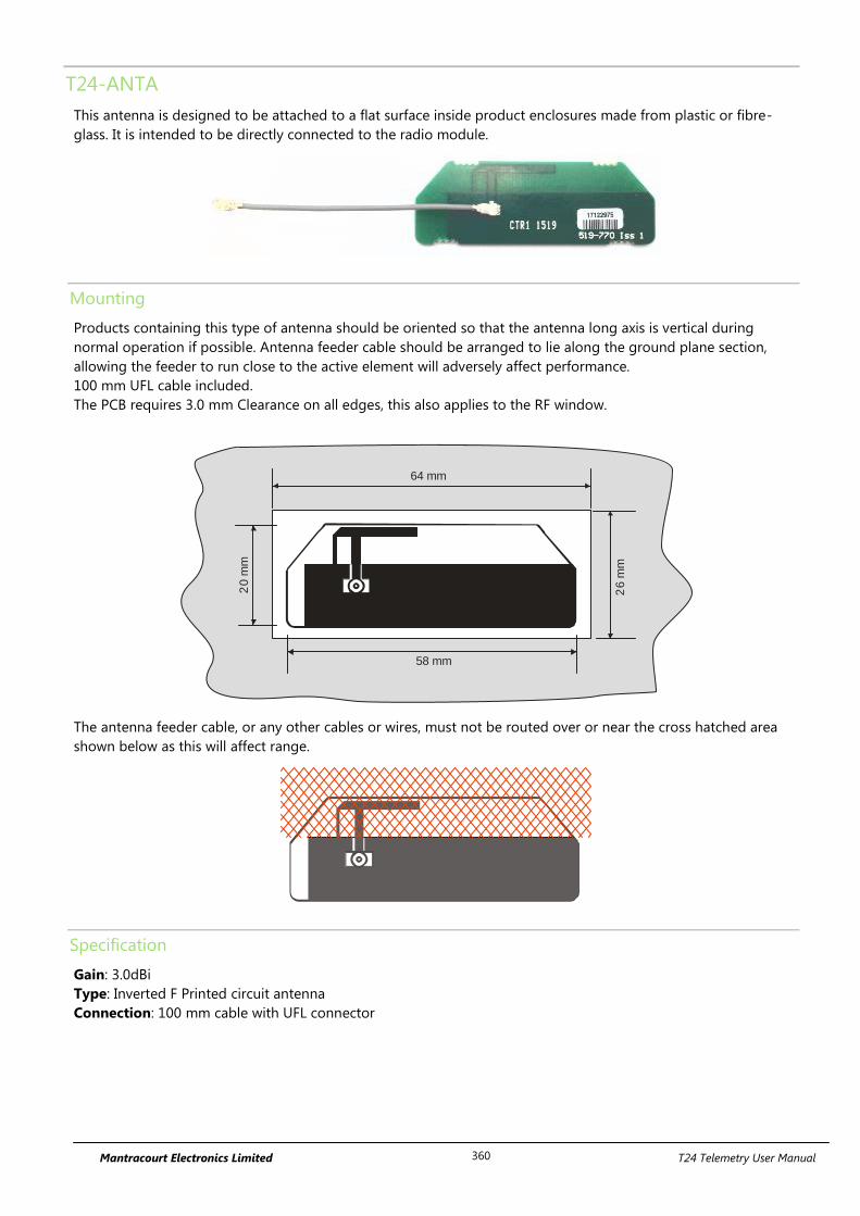
Mantracourt Electronics Limited T24 Telemetry User Manual 360
T24-ANTA
This antenna is designed to be attached to a flat surface inside product enclosures made from plastic or fibre-
glass. It is intended to be directly connected to the radio module.
Mounting
Products containing this type of antenna should be oriented so that the antenna long axis is vertical during
normal operation if possible. Antenna feeder cable should be arranged to lie along the ground plane section,
allowing the feeder to run close to the active element will adversely affect performance.
100 mm UFL cable included.
The PCB requires 3.0 mm Clearance on all edges, this also applies to the RF window.
64 mm
58 mm
26 m
m
20 m
m
The antenna feeder cable, or any other cables or wires, must not be routed over or near the cross hatched area
shown below as this will affect range.
Specification
Gain: 3.0dBi
Type: Inverted F Printed circuit antenna
Connection: 100 mm cable with UFL connector
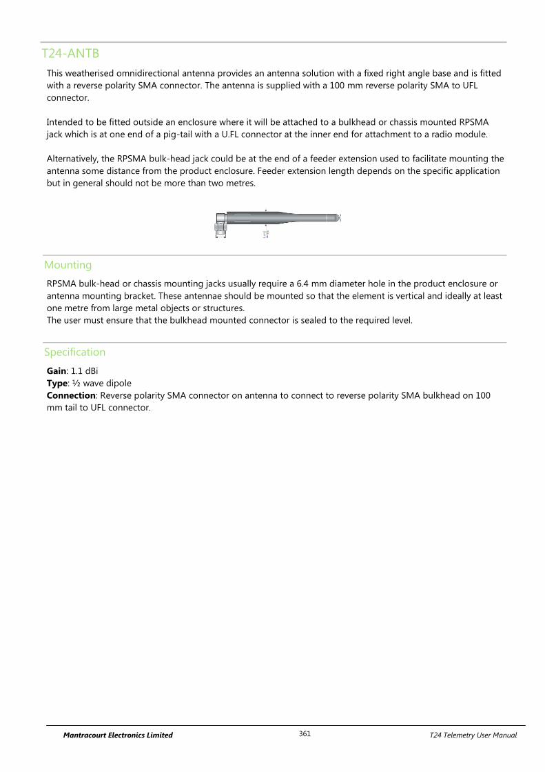
Mantracourt Electronics Limited T24 Telemetry User Manual 361
T24-ANTB
This weatherised omnidirectional antenna provides an antenna solution with a fixed right angle base and is fitted
with a reverse polarity SMA connector. The antenna is supplied with a 100 mm reverse polarity SMA to UFL
connector.
Intended to be fitted outside an enclosure where it will be attached to a bulkhead or chassis mounted RPSMA
jack which is at one end of a pig-tail with a U.FL connector at the inner end for attachment to a radio module.
Alternatively, the RPSMA bulk-head jack could be at the end of a feeder extension used to facilitate mounting the
antenna some distance from the product enclosure. Feeder extension length depends on the specific application
but in general should not be more than two metres.
Mounting
RPSMA bulk-head or chassis mounting jacks usually require a 6.4 mm diameter hole in the product enclosure or
antenna mounting bracket. These antennae should be mounted so that the element is vertical and ideally at least
one metre from large metal objects or structures.
The user must ensure that the bulkhead mounted connector is sealed to the required level.
Specification
Gain: 1.1 dBi
Type: ½ wave dipole
Connection: Reverse polarity SMA connector on antenna to connect to reverse polarity SMA bulkhead on 100
mm tail to UFL connector.
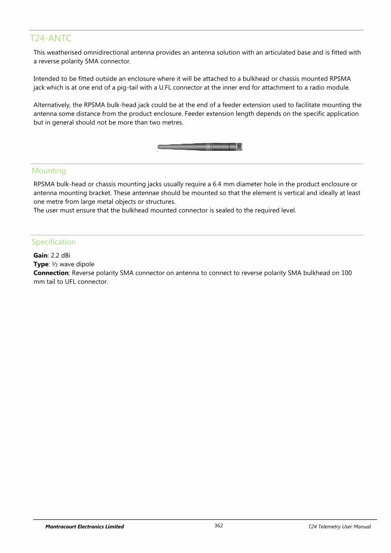
Mantracourt Electronics Limited T24 Telemetry User Manual 362
T24-ANTC
This weatherised omnidirectional antenna provides an antenna solution with an articulated base and is fitted with
a reverse polarity SMA connector.
Intended to be fitted outside an enclosure where it will be attached to a bulkhead or chassis mounted RPSMA
jack which is at one end of a pig-tail with a U.FL connector at the inner end for attachment to a radio module.
Alternatively, the RPSMA bulk-head jack could be at the end of a feeder extension used to facilitate mounting the
antenna some distance from the product enclosure. Feeder extension length depends on the specific application
but in general should not be more than two metres.
Mounting
RPSMA bulk-head or chassis mounting jacks usually require a 6.4 mm diameter hole in the product enclosure or
antenna mounting bracket. These antennae should be mounted so that the element is vertical and ideally at least
one metre from large metal objects or structures.
The user must ensure that the bulkhead mounted connector is sealed to the required level.
Specification
Gain: 2.2 dBi
Type: ½ wave dipole
Connection: Reverse polarity SMA connector on antenna to connect to reverse polarity SMA bulkhead on 100
mm tail to UFL connector.
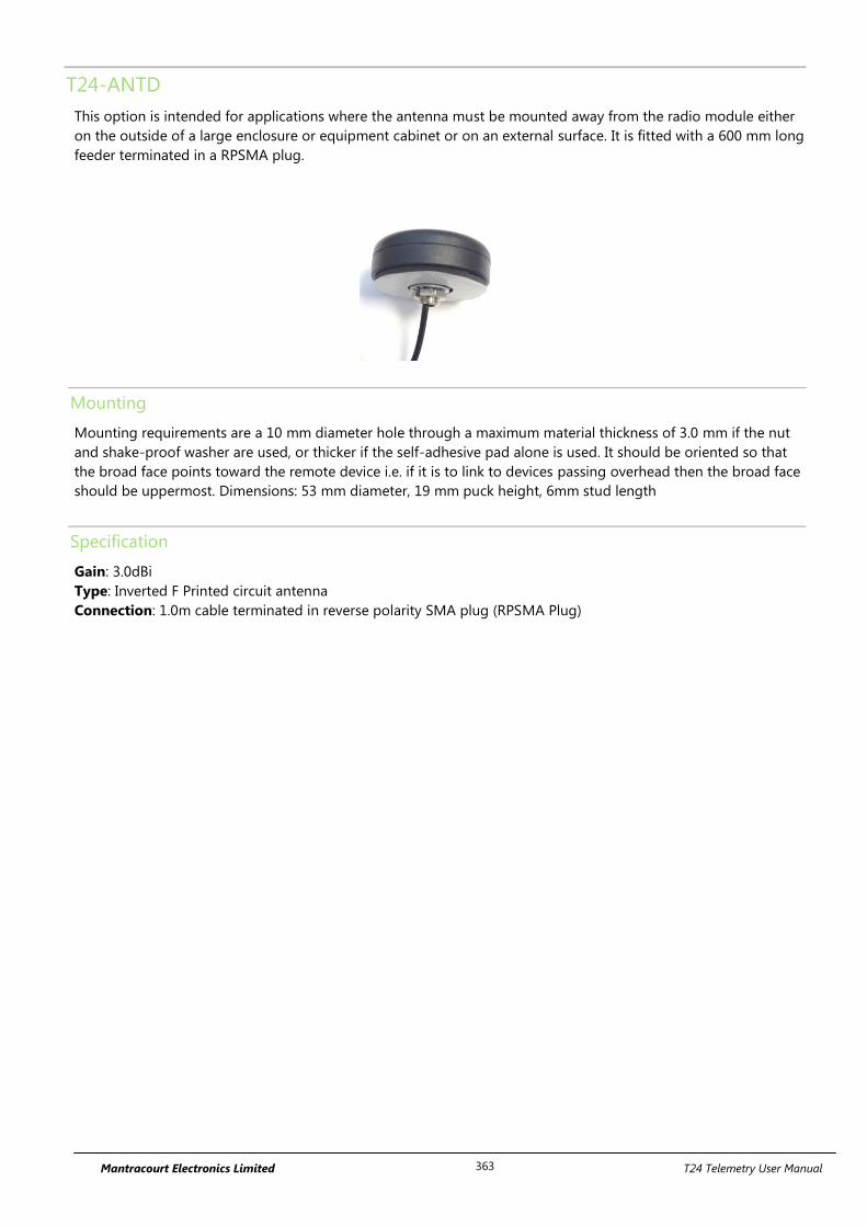
Mantracourt Electronics Limited T24 Telemetry User Manual 363
T24-ANTD
This option is intended for applications where the antenna must be mounted away from the radio module either
on the outside of a large enclosure or equipment cabinet or on an external surface. It is fitted with a 600 mm long
feeder terminated in a RPSMA plug.
Mounting
Mounting requirements are a 10 mm diameter hole through a maximum material thickness of 3.0 mm if the nut
and shake-proof washer are used, or thicker if the self-adhesive pad alone is used. It should be oriented so that
the broad face points toward the remote device i.e. if it is to link to devices passing overhead then the broad face
should be uppermost. Dimensions: 53 mm diameter, 19 mm puck height, 6mm stud length
Specification
Gain: 3.0dBi
Type: Inverted F Printed circuit antenna
Connection: 1.0m cable terminated in reverse polarity SMA plug (RPSMA Plug)
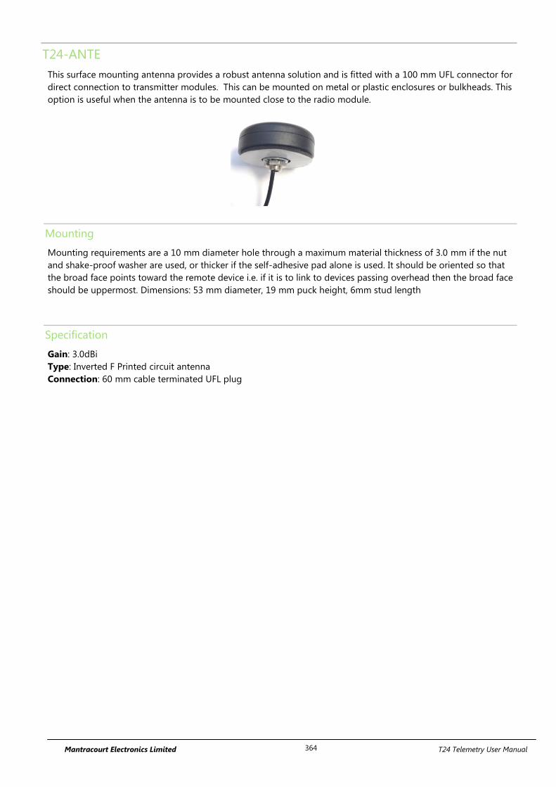
Mantracourt Electronics Limited T24 Telemetry User Manual 364
T24-ANTE
This surface mounting antenna provides a robust antenna solution and is fitted with a 100 mm UFL connector for
direct connection to transmitter modules. This can be mounted on metal or plastic enclosures or bulkheads. This
option is useful when the antenna is to be mounted close to the radio module.
Mounting
Mounting requirements are a 10 mm diameter hole through a maximum material thickness of 3.0 mm if the nut
and shake-proof washer are used, or thicker if the self-adhesive pad alone is used. It should be oriented so that
the broad face points toward the remote device i.e. if it is to link to devices passing overhead then the broad face
should be uppermost. Dimensions: 53 mm diameter, 19 mm puck height, 6mm stud length
Specification
Gain: 3.0dBi
Type: Inverted F Printed circuit antenna
Connection: 60 mm cable terminated UFL plug
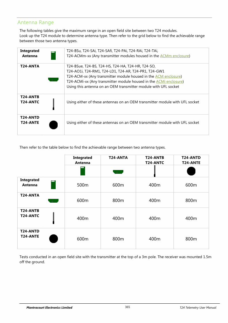
Mantracourt Electronics Limited T24 Telemetry User Manual 365
Antenna Range
The following tables give the maximum range in an open field site between two T24 modules.
Look up the T24 module to determine antenna type. Then refer to the grid below to find the achievable range
between those two antenna types.
Integrated
Antenna
T24-BSu, T24-SAi, T24-SAfi, T24-PAi, T24-RAi, T24-TAi,
T24-ACMm-xx (Any transmitter modules housed in the ACMm enclosure)
T24-ANTA
T24-BSue, T24-BS, T24-HS, T24-HA, T24-HR, T24-SO,
T24-AO1i, T24-RM1, T24-LD1, T24-AR, T24-PR1, T24-GW1
T24-ACM-xx (Any transmitter module housed in the ACM enclosure)
T24-ACMi-xx (Any transmitter module housed in the ACMi enclosure)
Using this antenna on an OEM transmitter module with UFL socket
T24-ANTB
T24-ANTC
Using either of these antennas on an OEM transmitter module with UFL socket
T24-ANTD
T24-ANTE
Using either of these antennas on an OEM transmitter module with UFL socket
Then refer to the table below to find the achievable range between two antenna types.
Integrated
Antenna
T24-ANTA T24-ANTB
T24-ANTC
T24-ANTD
T24-ANTE
Integrated
Antenna
500m 600m 400m 600m
T24-ANTA
600m 800m 400m 800m
T24-ANTB
T24-ANTC
400m 400m 400m 400m
T24-ANTD
T24-ANTE
600m 800m 400m 800m
Tests conducted in an open field site with the transmitter at the top of a 3m pole. The receiver was mounted 1.5m
off the ground.
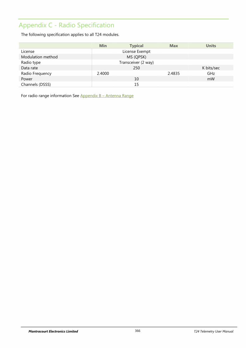
Mantracourt Electronics Limited T24 Telemetry User Manual 366
Appendix C - Radio Specification
The following specification applies to all T24 modules.
Min Typical Max Units
License License Exempt
Modulation method MS (QPSK)
Radio type Transceiver (2 way)
Data rate 250 K bits/sec
Radio Frequency 2.4000 2.4835 GHz
Power 10 mW
Channels (DSSS) 15
For radio range information See Appendix B – Antenna Range
Mantracourt Electronics Limited T24 Telemetry User Manual 367
Appendix D – Battery Selection
The following section applies to transmitter modules. Some enclosures will determine the battery type and size.
Considerations When Selecting Batteries
Re-chargeable or replacement
This really depends on the application. Some applications where expected battery life with alkaline batteries will
be many years would probably not warrant the use of re-chargeable batteries. Re-chargeable batteries have
implementation issues such as how to connect to the charger, how to seal this connection if required, can the
batteries be re-charged at a convenient point in the operation of the module i.e. between shifts and does the
voltage, when charging, exceed the maximum supply voltage of the transmitter module if so the inline charging
module will need to be fitted.
Required battery life
Driven by the application and mainly dependent on measurement rate and sample time. The operation would
normally require that the transmitter module is used in Low Power Mode to maximise battery life.
Size of
Choosing a battery will be influenced by how much space is available and what battery life is required, generally
the bigger the battery the longer it will last.
Operating temperature range
A battery’s useable capacity is influenced by its operating temperature. Generally, the lower the temperature the
lower their ability to provide charge. Beware of the batteries specified operating range when considering a
particular battery technology.
Self-discharge.
Batteries are chemical devices and have a shelf life which needs to be considered in application where long
battery life is required. Typically an Alkaline has a battery life of 5 years.
Internal Resistance of battery
Low internal resistance is important, the higher the resistance the less useful life of the battery is available. This is
due to voltage drops caused during the high current phase of the measurement cycle. In the case of a T24-SAf
strain gauge input module 300mA required for 250us. Batteries with an internal resistance greater than 150 milli
ohm may require additional capacitor modules to supply the peak current.
Connections to battery
For the same reasons internal resistance must be low it is important to keep any voltage drops from the battery
to the transmitter module as low as possible too. Care must be taken in selecting the connection method
between batteries and transmitter module. For example cables should be kept as short and thick as possible.
If sourcing battery holders for OEM transmitter modules be aware that some holders with springs only on one
side of the battery can temporarily disconnect a battery when subjected to a shock force. This may have the
unexpected effect of resetting or restarting a module. In the case of a transmitter module that is in a deep sleep
mode this may wake the module.
Mantracourt Electronics Limited T24 Telemetry User Manual 368
For example, a transmitter module mounted aboard a vehicle may not achieve the calculated battery life because
bumps in the road may have reset the module from its deep sleep mode. Utilising a Sleep Delay in transmitter
modules will alleviate this issue by returning the modules to deep sleep after a period of inactivity.
Environmental
Other considerations when selecting a connection method to the Batteries is the effect of vibration. A standard
battery holder is a poor choice in applications when the module can be subject to vibration. This is due to the
interruption of supply from the battery to the transmitter module caused when the spring arrangement holding
the battery to the terminal of the holder is defeated.
Corrosion of terminals must also be considered as this will also introduce resistance into the supply connections.
This could be overcome by ensuring the enclosure is sealed.
Optimising battery life
Battery life can be optimised by considering the following:
Use of low power mode.
Transmission interval.
Required Measurement resolution (Sample time).
Sleep / Wake configuration
Auto-Sleep duration.
Mantracourt Electronics Limited T24 Telemetry User Manual 369
Battery Types
Battery Type
Notes
Lithium Iron Disulphide
Li-FeS2
These can be found at 1.5 volts in AA size and can therefore be a direct replacement
for Alkaline cells. The low internal resistance and high capacity make these batteries
an ideal choice. The shelf life is around 20 years.
Recommended for AA battery powered modules: Energizer Ultimate Lithium L91
Alkaline
Zn-MnO2
Pairs of alkaline 1.5 V cells are the most common. Use D cells for maximum life and
AA cells where space is restricted. Typical capacity is 2Ah.
Example: Varta 4014 (D), Varta 4006 (AA)
Nickel Metal Hydride
NiMh
Most cells are 1.2 V so two in series gives 2.4 V. These can match alkaline batteries in
capacity but as the charged voltage is lower they do not match the usable capacity.
These batteries self discharge at a faster rate than alkalines. If charging these cells in
circuit precautions must be taken to ensure that the maximum voltage on the
transmitter module is not exceeded.
Example: GP 270AAHC (AA)
Nickel Cadmium
NiCad
Most cells are 1.2 V so two in series gives 2.4 V. Three in series can be used to give
3.6 volts. These do not have the usable capacity of an alkaline battery. These are
generally only useful if they are to be charged on a regular basis. If charging these
cells in circuit precautions must be taken to ensure that the maximum voltage on the
transmitter module is not exceeded.
Lithium Primary 3.6V
Li-SOCl2
Lithium cells can be used but note that the maximum voltage is 3.6 V.
Select a cell with low internal resistance.
Example: Saft LS17500 (A), Saft LSH20 (D)
Recommend T24-BC1 module as these cells usually have a high internal resistance.
Lithium Ion and Lithium
Polymer
Li ion, LiPo
These generally start at 3.7 V and exceed the maximum allowable voltage. These are
usable if a regulator and charging circuit can be installed between the transmitter
module and the battery. Care must be taken here that the regulator does not draw
too much current when idle so that the low power modes are not compromised.
Recommend T24-BC1 module.
Mantracourt Electronics Limited T24 Telemetry User Manual 370
Appendix E – Approval Statements
CE
Complies with EMC directive. 2004/108/EC The Radio Equipment and Telecommunications Terminal Equipment (R&TTE) Directive, 1999/5/EC,
European Community, Switzerland, Norway, Iceland, and Liechtenstein
English: This equipment is in compliance with the essential requirements and other relevant provisions of Directive 1999/5/EC.
Deutsch: Dieses Gerät entspricht den grundlegenden Anforderungen und den weiteren entsprecheneden
Vorgaben der Richtlinie 1999/5/EU.
Dansk: Dette udstyr er i overensstemmelse med de væsentlige krav og andre relevante bestemmelser i Directiv
1999/5/EF.
Español: Este equipo cumple con los requisitos esenciales asi como con otras disposiciones de la Directive
1999/5/EC.
Français: Cet appareil est conforme aux exigencies essentialles et aux autres dispositions pertinantes de la
Directive 1999/5/EC.
Íslenska: Þessi búnaður samrýmist lögboðnum kröfum og öðrum ákvæðum tilskipunar 1999/5/ESB.
Italiano: Questo apparato é conforme ai requisiti essenziali ed agli altri principi sanciti dalla Direttiva 1999/5/EC.
Nederlands: Deze apparatuur voldoet aan de belangrijkste eisen en andere voorzieningen van richtlijn 1999/5/EC.
Norsk: Dette utstyret er i samsvar med de grunnleggende krav og andre relevante bestemmelser i EU-directiv
1999/5/EC.
Português: Este equipamento satisfaz os requisitos essenciais e outras provisões da Directiva 1999/5/EC.
Suomalainen: Tämä laite täyttää direktiivin 1999/5/EY oleelliset vaatimukset ja on siinä asetettujen muidenkin ehtojen
mukainen.
Svenska: Denna utrustning är i överensstämmelse med de väsentliga kraven och andra relevanta bestämmelser i
Direktiv 1999/5/EC.
This equipment is in compliance with the essential requirements and other relevant provisions of Directive 1999/5/EC.
Manufactured in the UK by: Mantracourt Electronics Ltd, The Drive, Farringdon, Exeter, Devon, EX5 2JB, UK
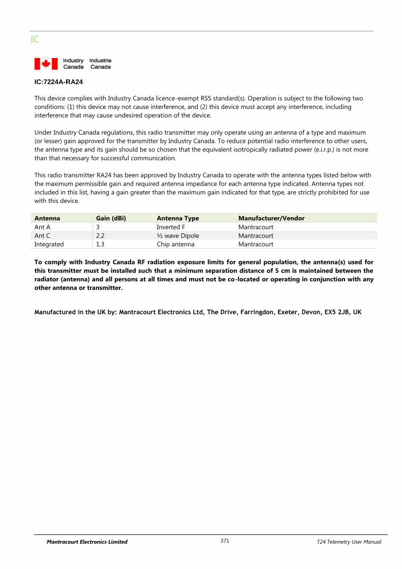
Mantracourt Electronics Limited T24 Telemetry User Manual 371
IC
IC:7224A-RA24
This device complies with Industry Canada licence-exempt RSS standard(s). Operation is subject to the following two
conditions: (1) this device may not cause interference, and (2) this device must accept any interference, including
interference that may cause undesired operation of the device.
Under Industry Canada regulations, this radio transmitter may only operate using an antenna of a type and maximum
(or lesser) gain approved for the transmitter by Industry Canada. To reduce potential radio interference to other users,
the antenna type and its gain should be so chosen that the equivalent isotropically radiated power (e.i.r.p.) is not more
than that necessary for successful communication.
This radio transmitter RA24 has been approved by Industry Canada to operate with the antenna types listed below with
the maximum permissible gain and required antenna impedance for each antenna type indicated. Antenna types not
included in this list, having a gain greater than the maximum gain indicated for that type, are strictly prohibited for use
with this device.
Antenna Gain (dBi) Antenna Type Manufacturer/Vendor
Ant A 3 Inverted F Mantracourt
Ant C 2.2 ½ wave Dipole Mantracourt
Integrated 1.3 Chip antenna Mantracourt
To comply with Industry Canada RF radiation exposure limits for general population, the antenna(s) used for
this transmitter must be installed such that a minimum separation distance of 5 cm is maintained between the
radiator (antenna) and all persons at all times and must not be co-located or operating in conjunction with any
other antenna or transmitter.
Manufactured in the UK by: Mantracourt Electronics Ltd, The Drive, Farringdon, Exeter, Devon, EX5 2JB, UK
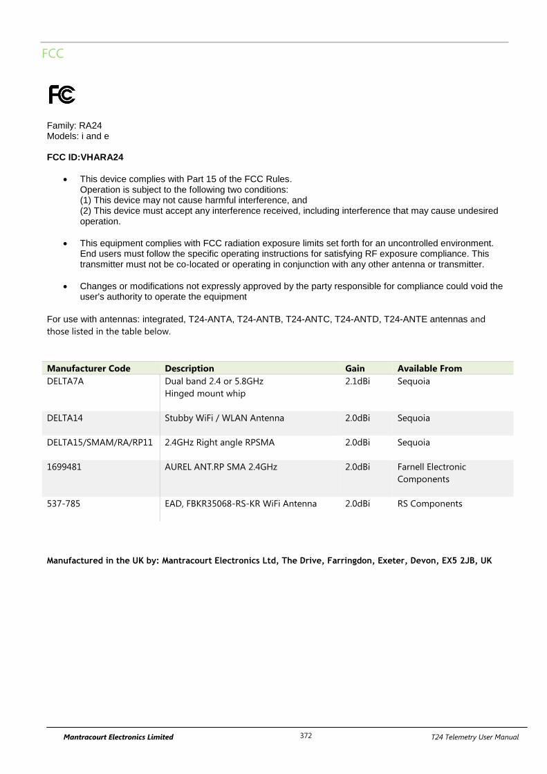
Mantracourt Electronics Limited T24 Telemetry User Manual 372
FCC
Family: RA24 Models: i and e FCC ID:VHARA24
This device complies with Part 15 of the FCC Rules. Operation is subject to the following two conditions: (1) This device may not cause harmful interference, and (2) This device must accept any interference received, including interference that may cause undesired operation.
This equipment complies with FCC radiation exposure limits set forth for an uncontrolled environment. End users must follow the specific operating instructions for satisfying RF exposure compliance. This transmitter must not be co-located or operating in conjunction with any other antenna or transmitter.
Changes or modifications not expressly approved by the party responsible for compliance could void the user's authority to operate the equipment
For use with antennas: integrated, T24-ANTA, T24-ANTB, T24-ANTC, T24-ANTD, T24-ANTE antennas and
those listed in the table below.
Manufacturer Code Description Gain Available From
DELTA7A
Dual band 2.4 or 5.8GHz
Hinged mount whip
2.1dBi Sequoia
DELTA14 Stubby WiFi / WLAN Antenna
2.0dBi Sequoia
DELTA15/SMAM/RA/RP11
2.4GHz Right angle RPSMA
2.0dBi
Sequoia
1699481 AUREL ANT.RP SMA 2.4GHz 2.0dBi Farnell Electronic
Components
537-785 EAD, FBKR35068-RS-KR WiFi Antenna 2.0dBi RS Components
Manufactured in the UK by: Mantracourt Electronics Ltd, The Drive, Farringdon, Exeter, Devon, EX5 2JB, UK
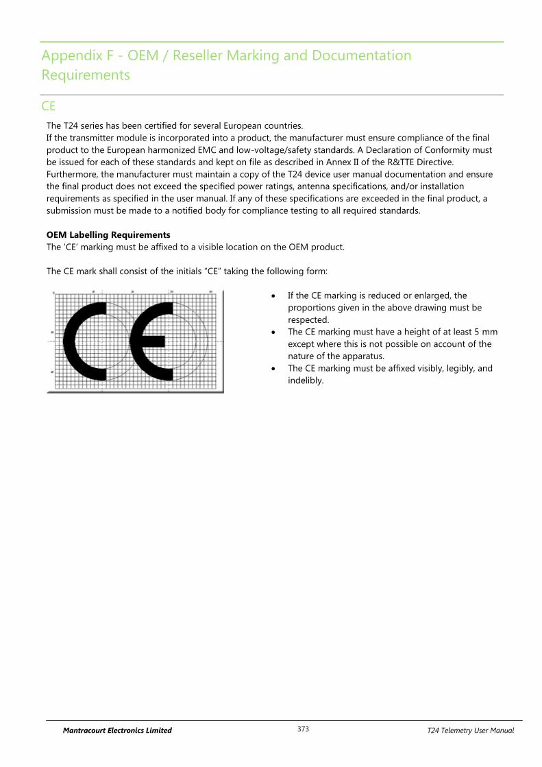
Mantracourt Electronics Limited T24 Telemetry User Manual 373
Appendix F - OEM / Reseller Marking and Documentation
Requirements
CE
The T24 series has been certified for several European countries.
If the transmitter module is incorporated into a product, the manufacturer must ensure compliance of the final
product to the European harmonized EMC and low-voltage/safety standards. A Declaration of Conformity must
be issued for each of these standards and kept on file as described in Annex II of the R&TTE Directive.
Furthermore, the manufacturer must maintain a copy of the T24 device user manual documentation and ensure
the final product does not exceed the specified power ratings, antenna specifications, and/or installation
requirements as specified in the user manual. If any of these specifications are exceeded in the final product, a
submission must be made to a notified body for compliance testing to all required standards.
OEM Labelling Requirements
The ‘CE’ marking must be affixed to a visible location on the OEM product.
The CE mark shall consist of the initials “CE” taking the following form:
If the CE marking is reduced or enlarged, the
proportions given in the above drawing must be
respected.
The CE marking must have a height of at least 5 mm
except where this is not possible on account of the
nature of the apparatus.
The CE marking must be affixed visibly, legibly, and
indelibly.
Mantracourt Electronics Limited T24 Telemetry User Manual 374
IC
The RA24 Module has been certified for integration into products only by OEM integrators under the following
conditions:
1. The antenna(s) must be installed such that a minimum separation distance of 5cm is maintained between
the radiator (antenna) and all persons at all times.
2. The transmitter module must not be co-located or operating in conjunction with any other antenna or
transmitter.
As long as the two conditions above are met, further transmitter testing will not be required. However, the OEM
integrator is still responsible for testing their end-product for any additional compliance requirements required
with this module installed (for example, digital device emissions, PC peripheral requirements, etc.).
IMPORTANT NOTE: In the event that these conditions cannot be met (for certain configurations or co-location
with another transmitter), then Industry Canada certification is no longer considered valid and the IC Certification
Number cannot be used on the final product. In these circumstances, the OEM integrator will be responsible for
re-evaluating the end product (including the transmitter) and obtaining a separate Industry Canada authorization.
End Product Labelling
The RA24 Module is labelled with its own IC Certification Number. If the IC Certification Number is not visible
when the module is installed inside another device, then the outside of the device into which the module is
installed must also display a label referring to the enclosed module. In that case, the final end product must be
labelled in a visible area with the following:
Contains Model RA24 Radio (2.4 GHz), IC:7224A-RA24
The OEM of the RA24 Module must only use the approved antenna(s) listed above, which have been certified with
this module.
The OEM integrator has to be aware not to provide information to the end user regarding how to install or
remove this RF module or change RF related parameters in the user’s manual of the end product.
The user’s manual for the end product must include the following information in a prominent location:
“To comply with Industry Canada RF radiation exposure limits for general population, the antenna(s) used
for this transmitter must be installed such that a minimum separation distance of 5 cm is maintained
between the radiator (antenna) and all persons at all times and must not be co-located or operating in
conjunction with any other antenna or transmitter.”
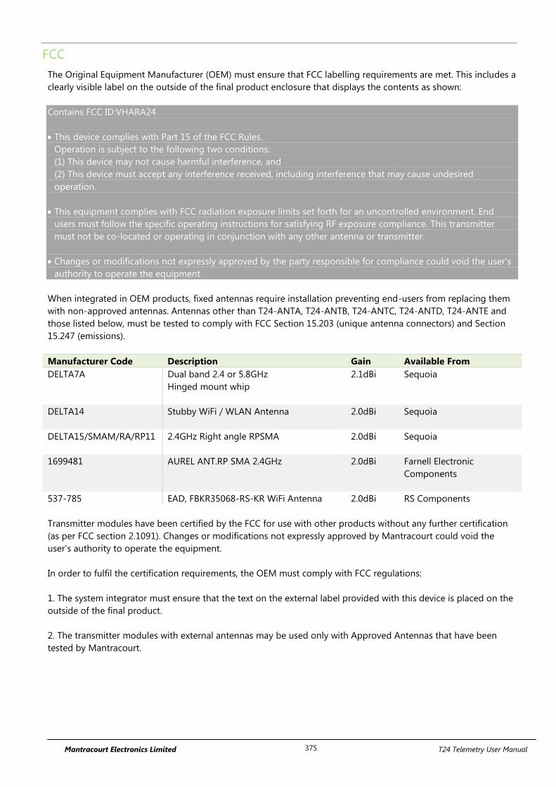
Mantracourt Electronics Limited T24 Telemetry User Manual 375
FCC
The Original Equipment Manufacturer (OEM) must ensure that FCC labelling requirements are met. This includes a
clearly visible label on the outside of the final product enclosure that displays the contents as shown:
Contains FCC ID:VHARA24
This device complies with Part 15 of the FCC Rules.
Operation is subject to the following two conditions:
(1) This device may not cause harmful interference, and
(2) This device must accept any interference received, including interference that may cause undesired
operation.
This equipment complies with FCC radiation exposure limits set forth for an uncontrolled environment. End
users must follow the specific operating instructions for satisfying RF exposure compliance. This transmitter
must not be co-located or operating in conjunction with any other antenna or transmitter.
Changes or modifications not expressly approved by the party responsible for compliance could void the user's
authority to operate the equipment
When integrated in OEM products, fixed antennas require installation preventing end-users from replacing them
with non-approved antennas. Antennas other than T24-ANTA, T24-ANTB, T24-ANTC, T24-ANTD, T24-ANTE and
those listed below, must be tested to comply with FCC Section 15.203 (unique antenna connectors) and Section
15.247 (emissions).
Manufacturer Code Description Gain Available From
DELTA7A
Dual band 2.4 or 5.8GHz
Hinged mount whip
2.1dBi Sequoia
DELTA14 Stubby WiFi / WLAN Antenna
2.0dBi Sequoia
DELTA15/SMAM/RA/RP11
2.4GHz Right angle RPSMA
2.0dBi
Sequoia
1699481 AUREL ANT.RP SMA 2.4GHz 2.0dBi Farnell Electronic
Components
537-785 EAD, FBKR35068-RS-KR WiFi Antenna 2.0dBi RS Components
Transmitter modules have been certified by the FCC for use with other products without any further certification
(as per FCC section 2.1091). Changes or modifications not expressly approved by Mantracourt could void the
user’s authority to operate the equipment.
In order to fulfil the certification requirements, the OEM must comply with FCC regulations:
1. The system integrator must ensure that the text on the external label provided with this device is placed on the
outside of the final product.
2. The transmitter modules with external antennas may be used only with Approved Antennas that have been
tested by Mantracourt.

Mantracourt Electronics Limited T24 Telemetry User Manual 376
Appendix G - Worldwide Regional Approvals
Region Product Conforms To
Europe CE
USA FCC
Canada IC
Important Note
Mantracourt does not list the entire set of standards that must be met for each country. Mantracourt customers
assume full responsibility for learning and meeting the required guidelines for each country in their distribution
market.
For more information relating to European compliance of an OEM product incorporating the T24 range of
modules, contact Mantracourt, or refer to the following web site: www.ero.dk
Mantracourt Electronics Limited T24 Telemetry User Manual 377
Appendix H - Declaration of Conformity
Declaration of Conformity
We,
Mantracourt Electronics Ltd
The Drive
Farringdon
Exeter
Devon
EX5 2JB
+44 1395 232020
declare under our sole responsibility that our products in the T24 Radio
Telemetry Product Range to which this declaration relates conform to the
essential requirements and other related requirements of the following
directives:
The R&TTE Directive 1999/05/EC
The RoHS Directive 2011/65/EU
The LV Directive 2006/95/EC
Date: June 2015
Signed:
Brett James
Development Manager
Mantracourt Electronics Limited.
FCC ID: VHARA24 IC:7224A-RA24

Mantracourt Electronics Limited T24 Telemetry User Manual 378
Appendix I - Warranty
Warranty
All Telemetry products from Mantracourt Electronics Ltd.,
('Mantracourt') are warranted against defective material and
workmanship for a period of one (1) year from the date of
dispatch.
If the 'Mantracourt' product you purchase appears to have a
defect in material or workmanship or fails during normal use
within the period, please contact your Distributor, who will assist
you in resolving the problem. If it is necessary to return the
product to 'Mantracourt' please include a note stating name,
company, address, phone number and a detailed description of
the problem. Also, please indicate if it is a warranty repair.
The sender is responsible for shipping charges, freight insurance
and proper packaging to prevent breakage in transit.
'Mantracourt' warranty does not apply to defects resulting from
action of the buyer such as mishandling, improper interfacing,
operation outside of design limits, improper repair or
unauthorised modification.
No other warranties are expressed or implied. 'Mantracourt'
specifically disclaims any implied warranties of merchantability or
fitness for a specific purpose.
The remedies outlined above are the buyer’s only remedies.
'Mantracourt' will not be liable for direct, indirect, special,
incidental or consequential damages whether based on the
contract, tort or other legal theory.
Any corrective maintenance required after the warranty period
should be performed by 'Mantracourt' approved personnel only.
Mantracourt Electronics Limited T24 Telemetry User Manual 379
Document Title: T24 Telemetry User Manual
Applies To: T24 Product Range
Part Number: 517-937
Issue Number: 1.0r
Dated: 23rd February 2016
In the interests of continued product development, Mantracourt Electronics Limited
reserves the right to alter product specifications without prior notice.
www.mantracourt.com